8086 INSTRUCTION SET - Bilgisayar Mühendisliği Bölümü...
30
Page 1 8086 INSTRUCTION SET DATA TRANSFER INSTRUCTIONS MOV – MOV Destination, Source The MOV instruction copies a word or byte of data from a specified source to a specified destination. The destination can be a register or a memory location. The source can be a register, a memory location or an immediate number. The source and destination cannot both be memory locations. They must both be of the same type (bytes or words). MOV instruction does not affect any flag. MOV CX, 037AH Put immediate number 037AH to CX MOV BL, [437AH] Copy byte in DS at offset 437AH to BL MOV AX, BX Copy content of register BX to AX MOV DL, [BX] Copy byte from memory at [BX] to DL MOV DS, BX Copy word from BX to DS register MOV RESULT [BP], AX Copy AX to two memory locations; AL to the first location, AH to the second; EA of the first memory location is sum of the displacement represented by RESULTS and content of BP. Physical address = EA + SS. MOV ES: RESULTS [BP], AX Same as the above instruction, but physical address = EA + ES, because of the segment override prefix ES XCHG – XCHG Destination, Source The XCHG instruction exchanges the content of a register with the content of another register or with the content of memory location(s). It cannot directly exchange the content of two memory locations. The source and destination must both be of the same type (bytes or words). The segment registers cannot be used in this instruction. This instruction does not affect any flag. XCHG AX, DX Exchange word in AX with word in DX XCHG BL, CH Exchange byte in BL with byte in CH XCHG AL, PRICES [BX] Exchange byte in AL with byte in memory at EA = PRICE [BX] in DS. LEA – LEA Register, Source This instruction determines the offset of the variable or memory location named as the source and puts this offset in the indicated 16-bit register. LEA does not affect any flag. LEA BX, PRICES Load BX with offset of PRICE in DS LEA BP, SS: STACK_TOP Load BP with offset of STACK_TOP in SS LEA CX, [BX][DI] Load CX with EA = [BX] + [DI] LDS – LDS Register, Memory address of the first word This instruction loads new values into the specified register and into the DS register from four successive memory locations. The word from two memory locations is copied into the specified register and the word from the next two memory locations is copied into the DS registers. LDS does not affect any flag. LDS BX, [4326] Copy content of memory at displacement 4326H in DS to BL, content of 4327H to BH. Copy content at displacement of 4328H and 4329H in DS to DS register. LDS SI, SPTR Copy content of memory at displacement SPTR and SPTR + 1
Transcript of 8086 INSTRUCTION SET - Bilgisayar Mühendisliği Bölümü...
Page 1
8086 INSTRUCTION SET
DATA TRANSFER INSTRUCTIONS
MOV – MOV Destination, Source
The MOV instruction copies a word or byte of data from a specified source to a specified destination. The
destination can be a register or a memory location. The source can be a register, a memory location or an
immediate number. The source and destination cannot both be memory locations. They must both be of
the same type (bytes or words). MOV instruction does not affect any flag.
MOV CX, 037AH Put immediate number 037AH to CX
MOV BL, [437AH] Copy byte in DS at offset 437AH to BL
MOV AX, BX Copy content of register BX to AX
MOV DL, [BX] Copy byte from memory at [BX] to DL
MOV DS, BX Copy word from BX to DS register
MOV RESULT [BP], AX Copy AX to two memory locations;
AL to the first location, AH to the second;
EA of the first memory location is sum of the displacement
represented by RESULTS and content of BP.
Physical address = EA + SS.
MOV ES: RESULTS [BP], AX Same as the above instruction, but physical address = EA + ES,
because of the segment override prefix ES
XCHG – XCHG Destination, Source
The XCHG instruction exchanges the content of a register with the content of another register or with the
content of memory location(s). It cannot directly exchange the content of two memory locations. The
source and destination must both be of the same type (bytes or words). The segment registers cannot be
used in this instruction. This instruction does not affect any flag.
XCHG AX, DX Exchange word in AX with word in DX
XCHG BL, CH Exchange byte in BL with byte in CH
XCHG AL, PRICES [BX] Exchange byte in AL with byte in memory at
EA = PRICE [BX] in DS.
LEA – LEA Register, Source
This instruction determines the offset of the variable or memory location named as the source and puts
this offset in the indicated 16-bit register. LEA does not affect any flag.
LEA BX, PRICES Load BX with offset of PRICE in DS
LEA BP, SS: STACK_TOP Load BP with offset of STACK_TOP in SS
LEA CX, [BX][DI] Load CX with EA = [BX] + [DI]
LDS – LDS Register, Memory address of the first word
This instruction loads new values into the specified register and into the DS register from four successive
memory locations. The word from two memory locations is copied into the specified register and the
word from the next two memory locations is copied into the DS registers. LDS does not affect any flag.
LDS BX, [4326] Copy content of memory at displacement 4326H in DS to BL,
content of 4327H to BH. Copy content at displacement of
4328H and 4329H in DS to DS register.
LDS SI, SPTR Copy content of memory at displacement SPTR and SPTR + 1
Page 2
in DS to SI register. Copy content of memory at displacements
SPTR + 2 and SPTR + 3 in DS to DS register. DS: SI now points
at start of the desired string.
LES – LES Register, Memory address of the first word
This instruction loads new values into the specified register and into the ES register from four successive
memory locations. The word from the first two memory locations is copied into the specified register, and
the word from the next two memory locations is copied into the ES register. LES does not affect any flag.
LES BX, [789AH] Copy content of memory at displacement 789AH in DS to BL,
content of 789BH to BH, content of memory at displacement
789CH and 789DH in DS is copied to ES register.
LES DI, [BX] Copy content of memory at offset [BX] and offset [BX] + 1 in
DS to DI register. Copy content of memory at offset [BX] + 2
and [BX] + 3 to ES register.
ARITHMETIC INSTRUCTIONS
ADD – ADD Destination, Source
ADC – ADC Destination, Source
These instructions add a number from some source to a number in some destination and put the result in
the specified destination. The ADC also adds the status of the carry flag to the result. The source may be
an immediate number, a register, or a memory location. The destination may be a register or a memory
location. The source and the destination in an instruction cannot both be memory locations. The source
and the destination must be of the same type (bytes or words). If you want to add a byte to a word, you
must copy the byte to a word location and fill the upper byte of the word with 0’s before adding. Flags
affected: AF, CF, OF, SF, ZF.
ADD AL, 74H Add immediate number 74H to content of AL. Result in AL
ADC CL, BL Add content of BL plus carry status to content of CL
ADD DX, BX Add content of BX to content of DX
ADD DX, [SI] Add word from memory at offset [SI] in DS to content of DX
ADC AL, PRICES [BX] Add byte from effective address PRICES [BX]
plus carry status to content of AL
ADD AL, PRICES [BX] Add content of memory at effective address PRICES [BX]
to AL
SUB – SUB Destination, Source
SBB – SBB Destination, Source
These instructions subtract the number in some source from the number in some destination and put the
result in the destination. The SBB instruction also subtracts the content of carry flag from the destination.
The source may be an immediate number, a register or memory location. The destination can also be a
register or a memory location. However, the source and the destination cannot both be memory location.
The source and the destination must both be of the same type (bytes or words). If you want to subtract a
byte from a word, you must first move the byte to a word location such as a 16-bit register and fill the
upper byte of the word with 0’s. Flags affected: AF, CF, OF, PF, SF, ZF.
SUB CX, BX CX – BX; Result in CX
SBB CH, AL Subtract content of AL and content of CF from content of CH.
Result in CH
SUB AX, 3427H Subtract immediate number 3427H from AX
SBB BX, [3427H] Subtract word at displacement 3427H in DS and content of CF

Page 3
from BX
SUB PRICES [BX], 04H Subtract 04 from byte at effective address PRICES [BX],
if PRICES is declared with DB; Subtract 04 from word at
effective address PRICES [BX], if it is declared with DW.
SBB CX, TABLE [BX] Subtract word from effective address TABLE [BX]
and status of CF from CX.
SBB TABLE [BX], CX Subtract CX and status of CF from word in memory at
effective address TABLE[BX].
MUL – MUL Source
This instruction multiplies an unsigned byte in some source with an unsigned byte in AL register or an
unsigned word in some source with an unsigned word in AX register. The source can be a register or a
memory location. When a byte is multiplied by the content of AL, the result (product) is put in AX. When
a word is multiplied by the content of AX, the result is put in DX and AX registers. If the most significant
byte of a 16-bit result or the most significant word of a 32-bit result is 0, CF and OF will both be 0’s. AF,
PF, SF and ZF are undefined after a MUL instruction.
If you want to multiply a byte with a word, you must first move the byte to a word location such as an
extended register and fill the upper byte of the word with all 0’s. You cannot use the CBW instruction for
this, because the CBW instruction fills the upper byte with copies of the most significant bit of the lower
byte.
MUL BH Multiply AL with BH; result in AX
MUL CX Multiply AX with CX; result high word in DX, low word in AX
MUL BYTE PTR [BX] Multiply AL with byte in DS pointed to by [BX]
MUL FACTOR [BX] Multiply AL with byte at effective address FACTOR [BX], if it
is declared as type byte with DB. Multiply AX with word at
effective address FACTOR [BX], if it is declared as type word
with DW.
MOV AX, MCAND_16 Load 16-bit multiplicand into AX
MOV CL, MPLIER_8 Load 8-bit multiplier into CL
MOV CH, 00H Set upper byte of CX to all 0’s
MUL CX AX times CX; 32-bit result in DX and AX
IMUL – IMUL Source
This instruction multiplies a signed byte from source with a signed byte in AL or a signed word from
some source with a signed word in AX. The source can be a register or a memory location. When a byte
from source is multiplied with content of AL, the signed result (product) will be put in AX. When a word
from source is multiplied by AX, the result is put in DX and AX. If the magnitude of the product does not
require all the bits of the destination, the unused byte / word will be filled with copies of the sign bit. If
the upper byte of a 16-bit result or the upper word of a 32-bit result contains only copies of the sign bit
(all 0’s or all 1’s), then CF and the OF will both be 0; If it contains a part of the product, CF and OF will
both be 1. AF, PF, SF and ZF are undefined after IMUL.
If you want to multiply a signed byte with a signed word, you must first move the byte into a word
location and fill the upper byte of the word with copies of the sign bit. If you move the byte into AL, you
can use the CBW instruction to do this.
IMUL BH Multiply signed byte in AL with signed byte in BH;
result in AX.
IMUL AX Multiply AX times AX; result in DX and AX
MOV CX, MULTIPLIER Load signed word in CX
MOV AL, MULTIPLICAND Load signed byte in AL
CBW Extend sign of AL into AH
IMUL CX Multiply CX with AX; Result in DX and AX
Page 4
DIV – DIV Source
This instruction is used to divide an unsigned word by a byte or to divide an unsigned double word (32
bits) by a word. When a word is divided by a byte, the word must be in the AX register. The divisor can
be in a register or a memory location. After the division, AL will contain the 8-bit quotient, and AH will
contain the 8-bit remainder. When a double word is divided by a word, the most significant word of the
double word must be in DX, and the least significant word of the double word must be in AX. After the
division, AX will contain the 16-bit quotient and DX will contain the 16-bit remainder. If an attempt is
made to divide by 0 or if the quotient is too large to fit in the destination (greater than FFH / FFFFH), the
8086 will generate a type 0 interrupt. All flags are undefined after a DIV instruction.
If you want to divide a byte by a byte, you must first put the dividend byte in AL and fill AH with all 0’s.
Likewise, if you want to divide a word by another word, then put the dividend word in AX and fill DX
with all 0’s.
DIV BL Divide word in AX by byte in BL; Quotient in AL, remainder in AH
DIV CX Divide down word in DX and AX by word in CX;
Quotient in AX, and remainder in DX.
DIV SCALE [BX] AX / (byte at effective address SCALE [BX]) if SCALE [BX] is of type
byte; or (DX and AX) / (word at effective address SCALE[BX]
if SCALE[BX] is of type word
IDIV – IDIV Source
This instruction is used to divide a signed word by a signed byte, or to divide a signed double word by a
signed word.
When dividing a signed word by a signed byte, the word must be in the AX register. The divisor can be in
an 8-bit register or a memory location. After the division, AL will contain the signed quotient, and AH
will contain the signed remainder. The sign of the remainder will be the same as the sign of the dividend.
If an attempt is made to divide by 0, the quotient is greater than 127 (7FH) or less than –127 (81H), the
8086 will automatically generate a type 0 interrupt.
When dividing a signed double word by a signed word, the most significant word of the dividend
(numerator) must be in the DX register, and the least significant word of the dividend must be in the AX
register. The divisor can be in any other 16-bit register or memory location. After the division, AX will
contain a signed 16-bit quotient, and DX will contain a signed 16-bit remainder. The sign of the
remainder will be the same as the sign of the dividend. Again, if an attempt is made to divide by 0, the
quotient is greater than +32,767 (7FFFH) or less than –32,767 (8001H), the 8086 will automatically
generate a type 0 interrupt.
All flags are undefined after an IDIV.
If you want to divide a signed byte by a signed byte, you must first put the dividend byte in AL and sign-
extend AL into AH. The CBW instruction can be used for this purpose. Likewise, if you want to divide a
signed word by a signed word, you must put the dividend word in AX and extend the sign of AX to all the
bits of DX. The CWD instruction can be used for this purpose.
IDIV BL Signed word in AX/signed byte in BL
IDIV BP Signed double word in DX and AX/signed word in BP
IDIV BYTE PTR [BX] AX / byte at offset [BX] in DS
INC – INC Destination
The INC instruction adds 1 to a specified register or to a memory location. AF, OF, PF, SF, and ZF are
updated, but CF is not affected. This means that if an 8-bit destination containing FFH or a 16-bit
destination containing FFFFH is incremented, the result will be all 0’s with no carry.

Page 5
INC BL Add 1 to contains of BL register
INC CX Add 1 to contains of CX register
INC BYTE PTR [BX] Increment byte in data segment at offset contained in BX.
INC WORD PTR [BX] Increment the word at offset of [BX] and [BX + 1]
in the data segment.
INC TEMP Increment byte or word named TEMP in the data segment.
Increment byte if MAX_TEMP declared with DB.
Increment word if MAX_TEMP is declared with DW.
INC PRICES [BX] Increment element pointed to by [BX] in array PRICES.
Increment a word if PRICES is declared as an array of words;
Increment a byte if PRICES is declared as an array of bytes.
DEC – DEC Destination
This instruction subtracts 1 from the destination word or byte. The destination can be a register or a
memory location. AF, OF, SF, PF, and ZF are updated, but CF is not affected. This means that if an 8-bit
destination containing 00H or a 16-bit destination containing 0000H is decremented, the result will be
FFH or FFFFH with no carry (borrow).
DEC CL Subtract 1 from content of CL register
DEC BP Subtract 1 from content of BP register
DEC BYTE PTR [BX] Subtract 1 from byte at offset [BX] in DS.
DEC WORD PTR [BP] Subtract 1 from a word at offset [BP] in SS.
DEC COUNT Subtract 1 from byte or word named COUNT in DS.
Decrement a byte if COUNT is declared with a DB;
Decrement a word if COUNT is declared with a DW.
DAA (DECIMAL ADJUST AFTER BCD ADDITION)
This instruction is used to make sure the result of adding two packed BCD numbers is adjusted to be a
legal BCD number. The result of the addition must be in AL for DAA to work correctly. If the lower
nibble in AL after an addition is greater than 9 or AF was set by the addition, then the DAA instruction
will add 6 to the lower nibble in AL. If the result in the upper nibble of AL in now greater than 9 or if the
carry flag was set by the addition or correction, then the DAA instruction will add 60H to AL.
Let AL = 59 BCD, and BL = 35 BCD
ADD AL, BL AL = 8EH; lower nibble > 9, add 06H to AL
DAA AL = 94 BCD, CF = 0
Let AL = 88 BCD, and BL = 49 BCD
ADD AL, BL AL = D1H; AF = 1, add 06H to AL
DAA AL = D7H; upper nibble > 9, add 60H to AL
AL = 37 BCD, CF = 1
The DAA instruction updates AF, CF, SF, PF, and ZF; but OF is undefined.
DAS (DECIMAL ADJUST AFTER BCD SUBTRACTION)
This instruction is used after subtracting one packed BCD number from another packed BCD number, to
make sure the result is correct packed BCD. The result of the subtraction must be in AL for DAS to work
correctly. If the lower nibble in AL after a subtraction is greater than 9 or the AF was set by the
subtraction, then the DAS instruction will subtract 6 from the lower nibble AL. If the result in the upper
nibble is now greater than 9 or if the carry flag was set, the DAS instruction will subtract 60 from AL.
Let AL = 86 BCD, and BH = 57 BCD
SUB AL, BH AL = 2FH; lower nibble > 9, subtract 06H from AL
AL = 29 BCD, CF = 0
Page 6
Let AL = 49 BCD, and BH = 72 BCD
SUB AL, BH AL = D7H; upper nibble > 9, subtract 60H from AL
DAS AL = 77 BCD, CF = 1 (borrow is needed)
The DAS instruction updates AF, CF, SF, PF, and ZF; but OF is undefined.
CBW (CONVERT SIGNED BYTE TO SIGNED WORD)
This instruction copies the sign bit of the byte in AL to all the bits in AH. AH is then said to be the sign
extension of AL. CBW does not affect any flag.
Let AX = 00000000 10011011 (–155 decimal)
CBW Convert signed byte in AL to signed word in AX
AX = 11111111 10011011 (–155 decimal)
CWD (CONVERT SIGNED WORD TO SIGNED DOUBLE WORD)
This instruction copies the sign bit of a word in AX to all the bits of the DX register. In other words, it
extends the sign of AX into all of DX. CWD affects no flags.
Let DX = 00000000 00000000, and AX = 11110000 11000111 (–3897 decimal)
CWD Convert signed word in AX to signed double word in DX:AX
DX = 11111111 11111111
AX = 11110000 11000111 (–3897 decimal)
AAA (ASCII ADJUST FOR ADDITION)
Numerical data coming into a computer from a terminal is usually in ASCII code. In this code, the
numbers 0 to 9 are represented by the ASCII codes 30H to 39H. The 8086 allows you to add the ASCII
codes for two decimal digits without masking off the “3” in the upper nibble of each. After the addition,
the AAA instruction is used to make sure the result is the correct unpacked BCD.
Let AL = 0011 0101 (ASCII 5), and BL = 0011 1001 (ASCII 9)
ADD AL, BL AL = 0110 1110 (6EH, which is incorrect BCD)
AAA AL = 0000 0100 (unpacked BCD 4)
CF = 1 indicates answer is 14 decimal.
The AAA instruction works only on the AL register. The AAA instruction updates AF and CF; but OF,
PF, SF and ZF are left undefined.
AAS (ASCII ADJUST FOR SUBTRACTION)
Numerical data coming into a computer from a terminal is usually in an ASCII code. In this code the
numbers 0 to 9 are represented by the ASCII codes 30H to 39H. The 8086 allows you to subtract the
ASCII codes for two decimal digits without masking the “3” in the upper nibble of each. The AAS
instruction is then used to make sure the result is the correct unpacked BCD.
Let AL = 00111001 (39H or ASCII 9), and BL = 00110101 (35H or ASCII 5)
SUB AL, BL AL = 00000100 (BCD 04), and CF = 0
AAS AL = 00000100 (BCD 04), and CF = 0 (no borrow required)
Let AL = 00110101 (35H or ASCII 5), and BL = 00111001 (39H or ASCII 9)
SUB AL, BL AL = 11111100 (– 4 in 2’s complement form), and CF = 1
AAS AL = 00000100 (BCD 06), and CF = 1 (borrow required)
The AAS instruction works only on the AL register. It updates ZF and CF; but OF, PF, SF, AF are left
undefined.
Page 7
AAM (BCD ADJUST AFTER MULTIPLY)
Before you can multiply two ASCII digits, you must first mask the upper 4 bit of each. This leaves
unpacked BCD (one BCD digit per byte) in each byte. After the two unpacked BCD digits are multiplied,
the AAM instruction is used to adjust the product to two unpacked BCD digits in AX. AAM works only
after the multiplication of two unpacked BCD bytes, and it works only the operand in AL. AAM updates
PF, SF and ZF but AF; CF and OF are left undefined.
Let AL = 00000101 (unpacked BCD 5), and BH = 00001001 (unpacked BCD 9)
MUL BH AL x BH: AX = 00000000 00101101 = 002DH
AAM AX = 00000100 00000101 = 0405H (unpacked BCD for 45)
AAD (BCD-TO-BINARY CONVERT BEFORE DIVISION)
AAD converts two unpacked BCD digits in AH and AL to the equivalent binary number in AL. This
adjustment must be made before dividing the two unpacked BCD digits in AX by an unpacked BCD byte.
After the BCD division, AL will contain the unpacked BCD quotient and AH will contain the unpacked
BCD remainder. AAD updates PF, SF and ZF; AF, CF and OF are left undefined.
Let AX = 0607 (unpacked BCD for 67 decimal), and CH = 09H
AAD AX = 0043 (43H = 67 decimal)
DIV CH AL = 07; AH = 04; Flags undefined after DIV
If an attempt is made to divide by 0, the 8086 will generate a type 0 interrupt.
LOGICAL INSTRUCTIONS
AND – AND Destination, Source
This instruction ANDs each bit in a source byte or word with the same numbered bit in a destination byte
or word. The result is put in the specified destination. The content of the specified source is not changed.
The source can be an immediate number, the content of a register, or the content of a memory location.
The destination can be a register or a memory location. The source and the destination cannot both be
memory locations. CF and OF are both 0 after AND. PF, SF, and ZF are updated by the AND instruction.
AF is undefined. PF has meaning only for an 8-bit operand.
AND CX, [SI] AND word in DS at offset [SI] with word in CX register;
Result in CX register
AND BH, CL AND byte in CL with byte in BH; Result in BH
AND BX, 00FFH 00FFH Masks upper byte, leaves lower byte unchanged.
OR – OR Destination, Source
This instruction ORs each bit in a source byte or word with the same numbered bit in a destination byte or
word. The result is put in the specified destination. The content of the specified source is not changed.
The source can be an immediate number, the content of a register, or the content of a memory location.
The destination can be a register or a memory location. The source and destination cannot both be
memory locations. CF and OF are both 0 after OR. PF, SF, and ZF are updated by the OR instruction. AF
is undefined. PF has meaning only for an 8-bit operand.
OR AH, CL CL ORed with AH, result in AH, CL not changed
Page 8
OR BP, SI SI ORed with BP, result in BP, SI not changed
OR SI, BP BP ORed with SI, result in SI, BP not changed
OR BL, 80H BL ORed with immediate number 80H; sets MSB of BL to 1
OR CX, TABLE [SI] CX ORed with word from effective address TABLE [SI];
Content of memory is not changed.
XOR – XOR Destination, Source
This instruction Exclusive-ORs each bit in a source byte or word with the same numbered bit in a
destination byte or word. The result is put in the specified destination. The content of the specified source
is not changed.
The source can be an immediate number, the content of a register, or the content of a memory location.
The destination can be a register or a memory location. The source and destination cannot both be
memory locations. CF and OF are both 0 after XOR. PF, SF, and ZF are updated. PF has meaning only
for an 8-bit operand. AF is undefined.
XOR CL, BH Byte in BH exclusive-ORed with byte in CL.
Result in CL. BH not changed.
XOR BP, DI Word in DI exclusive-ORed with word in BP.
Result in BP. DI not changed.
XOR WORD PTR [BX], 00FFH Exclusive-OR immediate number 00FFH with word at
offset [BX] in the data segment.
Result in memory location [BX]
NOT – NOT Destination
The NOT instruction inverts each bit (forms the 1’s complement) of a byte or word in the specified
destination. The destination can be a register or a memory location. This instruction does not affect any
flag.
NOT BX Complement content or BX register
NOT BYTE PTR [BX] Complement memory byte at offset [BX] in data segment.
NEG – NEG Destination
This instruction replaces the number in a destination with its 2’s complement. The destination can be a
register or a memory location. It gives the same result as the invert each bit and add one algorithm. The
NEG instruction updates AF, AF, PF, ZF, and OF.
NEG AL Replace number in AL with its 2’s complement
NEG BX Replace number in BX with its 2’s complement
NEG BYTE PTR [BX] Replace byte at offset BX in DX with its 2’s complement
NEG WORD PTR [BP] Replace word at offset BP in SS with its 2’s complement
CMP – CMP Destination, Source
This instruction compares a byte / word in the specified source with a byte / word in the specified
destination. The source can be an immediate number, a register, or a memory location. The destination
can be a register or a memory location. However, the source and the destination cannot both be memory
locations. The comparison is actually done by subtracting the source byte or word from the destination
byte or word. The source and the destination are not changed, but the flags are set to indicate the results of
the comparison. AF, OF, SF, ZF, PF, and CF are updated by the CMP instruction. For the instruction
CMP CX, BX, the values of CF, ZF, and SF will be as follows:
Page 9
CF ZF SF
CX = BX 0 1 0 Result of subtraction is 0
CX > BX 0 0 0 No borrow required, so CF = 0
CX < BX 1 0 1 Subtraction requires borrow, so CF = 1
CMP AL, 01H Compare immediate number 01H with byte in AL
CMP BH, CL Compare byte in CL with byte in BH
CMP CX, TEMP Compare word in DS at displacement TEMP with word at CX
CMP PRICES [BX], 49H Compare immediate number 49H with byte at offset [BX]
in array PRICES
TEST – TEST Destination, Source
This instruction ANDs the byte / word in the specified source with the byte / word in the specified
destination. Flags are updated, but neither operand is changed. The test instruction is often used to set
flags before a Conditional jump instruction.
The source can be an immediate number, the content of a register, or the content of a memory location.
The destination can be a register or a memory location. The source and the destination cannot both be
memory locations. CF and OF are both 0’s after TEST. PF, SF and ZF will be updated to show the results
of the destination. AF is be undefined.
TEST AL, BH AND BH with AL. No result stored; Update PF, SF, ZF.
TEST CX, 0001H AND CX with immediate number 0001H;
No result stored; Update PF, SF, ZF
TEST BP, [BX][DI] AND word are offset [BX][DI] in DS with word in BP.
No result stored. Update PF, SF, and ZF
ROTATE AND SHIFT INSTRUCTIONS
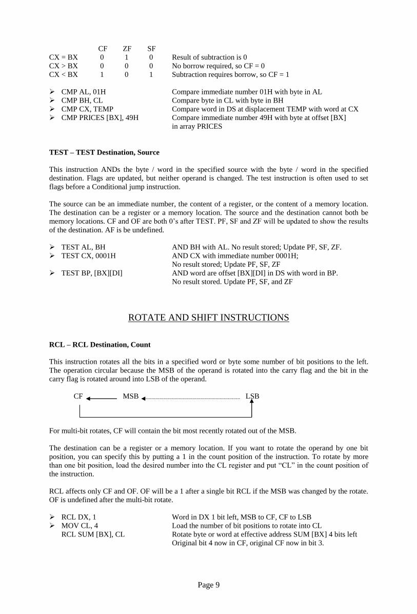
RCL – RCL Destination, Count
This instruction rotates all the bits in a specified word or byte some number of bit positions to the left.
The operation circular because the MSB of the operand is rotated into the carry flag and the bit in the
carry flag is rotated around into LSB of the operand.
CF MSB LSB
For multi-bit rotates, CF will contain the bit most recently rotated out of the MSB.
The destination can be a register or a memory location. If you want to rotate the operand by one bit
position, you can specify this by putting a 1 in the count position of the instruction. To rotate by more
than one bit position, load the desired number into the CL register and put “CL” in the count position of
the instruction.
RCL affects only CF and OF. OF will be a 1 after a single bit RCL if the MSB was changed by the rotate.
OF is undefined after the multi-bit rotate.
RCL DX, 1 Word in DX 1 bit left, MSB to CF, CF to LSB
MOV CL, 4 Load the number of bit positions to rotate into CL
RCL SUM [BX], CL Rotate byte or word at effective address SUM [BX] 4 bits left
Original bit 4 now in CF, original CF now in bit 3.

Page 10
RCR – RCR Destination, Count
This instruction rotates all the bits in a specified word or byte some number of bit positions to the right.
The operation circular because the LSB of the operand is rotated into the carry flag and the bit in the carry
flag is rotate around into MSB of the operand.
CF MSB LSB
For multi-bit rotate, CF will contain the bit most recently rotated out of the LSB.
The destination can be a register or a memory location. If you want to rotate the operand by one bit
position, you can specify this by putting a 1 in the count position of the instruction. To rotate more than
one bit position, load the desired number into the CL register and put “CL” in the count position of the
instruction.
RCR affects only CF and OF. OF will be a 1 after a single bit RCR if the MSB was changed by the rotate.
OF is undefined after the multi-bit rotate.
RCR BX, 1 Word in BX right 1 bit, CF to MSB, LSB to CF
MOV CL, 4 Load CL for rotating 4 bit position
RCR BYTE PTR [BX], 4 Rotate the byte at offset [BX] in DS 4 bit positions right
CF = original bit 3, Bit 4 – original CF.
ROL – ROL Destination, Count
This instruction rotates all the bits in a specified word or byte to the left some number of bit positions.
The data bit rotated out of MSB is circled back into the LSB. It is also copied into CF. In the case of
multiple-bit rotate, CF will contain a copy of the bit most recently moved out of the MSB.
CF MSB LSB
The destination can be a register or a memory location. If you to want rotate the operand by one bit
position, you can specify this by putting 1 in the count position in the instruction. To rotate more than one
bit position, load the desired number into the CL register and put “CL” in the count position of the
instruction.
ROL affects only CF and OF. OF will be a 1 after a single bit ROL if the MSB was changed by the rotate.
ROL AX, 1 Rotate the word in AX 1 bit position left, MSB to LSB and CF
MOV CL, 04H Load number of bits to rotate in CL
ROL BL, CL Rotate BL 4 bit positions
ROL FACTOR [BX], 1 Rotate the word or byte in DS at EA = FACTOR [BX]
by 1 bit position left into CF
ROR – ROR Destination, Count
This instruction rotates all the bits in a specified word or byte some number of bit positions to right. The
operation is desired as a rotate rather than shift, because the bit moved out of the LSB is rotated around
into the MSB. The data bit moved out of the LSB is also copied into CF. In the case of multiple bit
rotates, CF will contain a copy of the bit most recently moved out of the LSB.
CF MSB LSB
Page 11
The destination can be a register or a memory location. If you want to rotate the operand by one bit
position, you can specify this by putting 1 in the count position in the instruction. To rotate by more than
one bit position, load the desired number into the CL register and put “CL” in the count position of the
instruction.
ROR affects only CF and OF. OF will be a 1 after a single bit ROR if the MSB was changed by the rotate.
ROR BL, 1 Rotate all bits in BL right 1 bit position LSB to MSB and to CF
MOV CL, 08H Load CL with number of bit positions to be rotated
ROR WORD PTR [BX], CL Rotate word in DS at offset [BX] 8 bit position right
SAL – SAL Destination, Count
SHL – SHL Destination, Count
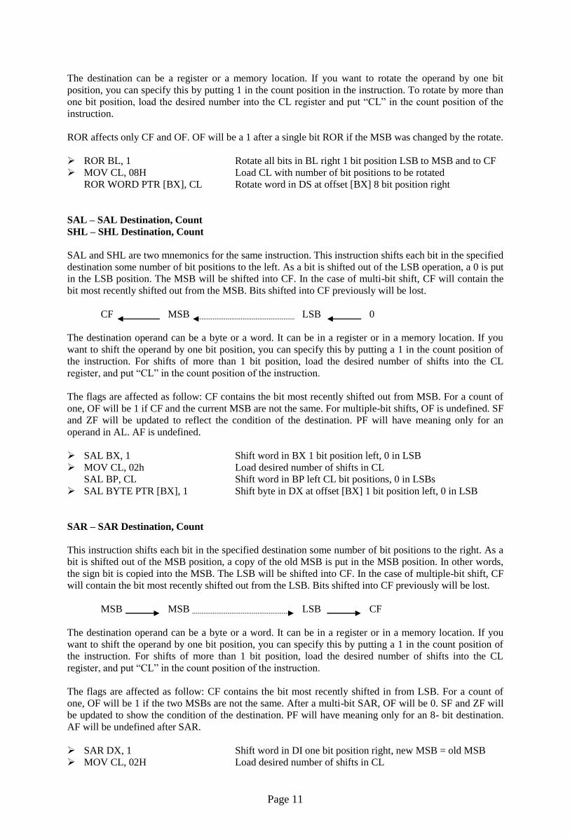
SAL and SHL are two mnemonics for the same instruction. This instruction shifts each bit in the specified
destination some number of bit positions to the left. As a bit is shifted out of the LSB operation, a 0 is put
in the LSB position. The MSB will be shifted into CF. In the case of multi-bit shift, CF will contain the
bit most recently shifted out from the MSB. Bits shifted into CF previously will be lost.
CF MSB LSB 0
The destination operand can be a byte or a word. It can be in a register or in a memory location. If you
want to shift the operand by one bit position, you can specify this by putting a 1 in the count position of
the instruction. For shifts of more than 1 bit position, load the desired number of shifts into the CL
register, and put “CL” in the count position of the instruction.
The flags are affected as follow: CF contains the bit most recently shifted out from MSB. For a count of
one, OF will be 1 if CF and the current MSB are not the same. For multiple-bit shifts, OF is undefined. SF
and ZF will be updated to reflect the condition of the destination. PF will have meaning only for an
operand in AL. AF is undefined.
SAL BX, 1 Shift word in BX 1 bit position left, 0 in LSB
MOV CL, 02h Load desired number of shifts in CL
SAL BP, CL Shift word in BP left CL bit positions, 0 in LSBs
SAL BYTE PTR [BX], 1 Shift byte in DX at offset [BX] 1 bit position left, 0 in LSB
SAR – SAR Destination, Count
This instruction shifts each bit in the specified destination some number of bit positions to the right. As a
bit is shifted out of the MSB position, a copy of the old MSB is put in the MSB position. In other words,
the sign bit is copied into the MSB. The LSB will be shifted into CF. In the case of multiple-bit shift, CF
will contain the bit most recently shifted out from the LSB. Bits shifted into CF previously will be lost.
MSB MSB LSB CF
The destination operand can be a byte or a word. It can be in a register or in a memory location. If you
want to shift the operand by one bit position, you can specify this by putting a 1 in the count position of
the instruction. For shifts of more than 1 bit position, load the desired number of shifts into the CL
register, and put “CL” in the count position of the instruction.
The flags are affected as follow: CF contains the bit most recently shifted in from LSB. For a count of
one, OF will be 1 if the two MSBs are not the same. After a multi-bit SAR, OF will be 0. SF and ZF will
be updated to show the condition of the destination. PF will have meaning only for an 8- bit destination.
AF will be undefined after SAR.
SAR DX, 1 Shift word in DI one bit position right, new MSB = old MSB
MOV CL, 02H Load desired number of shifts in CL
Page 12
SAR WORD PTR [BP], CL Shift word at offset [BP] in stack segment right by two bit
positions, the two MSBs are now copies of original LSB
SHR – SHR Destination, Count
This instruction shifts each bit in the specified destination some number of bit positions to the right. As a
bit is shifted out of the MSB position, a 0 is put in its place. The bit shifted out of the LSB position goes
to CF. In the case of multi-bit shifts, CF will contain the bit most recently shifted out from the LSB. Bits
shifted into CF previously will be lost.
0 MSB LSB CF
The destination operand can be a byte or a word in a register or in a memory location. If you want to shift
the operand by one bit position, you can specify this by putting a 1 in the count position of the instruction.
For shifts of more than 1 bit position, load the desired number of shifts into the CL register, and put “CL”
in the count position of the instruction.
The flags are affected by SHR as follow: CF contains the bit most recently shifted out from LSB. For a
count of one, OF will be 1 if the two MSBs are not both 0’s. For multiple-bit shifts, OF will be
meaningless. SF and ZF will be updated to show the condition of the destination. PF will have meaning
only for an 8-bit destination. AF is undefined.
SHR BP, 1 Shift word in BP one bit position right, 0 in MSB
MOV CL, 03H Load desired number of shifts into CL
SHR BYTE PTR [BX] Shift byte in DS at offset [BX] 3 bits right; 0’s in 3 MSBs
TRANSFER-OF-CONTROL INSTRUCTIONS
Note: The following rules apply to the discussions presented in this section.
The terms above and below are used when referring to the magnitude of unsigned numbers. For
example, the number 00000111 (7) is above the number 00000010 (2), whereas the number 00000100
(4) is below the number 00001110 (14).
The terms greater and less are used to refer to the relationship of two signed numbers. Greater means
more positive. The number 00000111 (+7) is greater than the number 11111110 (-2), whereas the
number 11111100 (-4) is less than the number 11110100 (-6).
In the case of Conditional jump instructions, the destination address must be in the range of –128
bytes to +127 bytes from the address of the next instruction
These instructions do not affect any flags.
JMP (UNCONDITIONAL JUMP TO SPECIFIED DESTINATION)
This instruction will fetch the next instruction from the location specified in the instruction rather than
from the next location after the JMP instruction. If the destination is in the same code segment as the JMP
instruction, then only the instruction pointer will be changed to get the destination location. This is
referred to as a near jump. If the destination for the jump instruction is in a segment with a name different
from that of the segment containing the JMP instruction, then both the instruction pointer and the code
segment register content will be changed to get the destination location. This referred to as a far jump.
The JMP instruction does not affect any flag.
JMP CONTINUE
This instruction fetches the next instruction from address at label CONTINUE. If the label is in the same
segment, an offset coded as part of the instruction will be added to the instruction pointer to produce the
new fetch address. If the label is another segment, then IP and CS will be replaced with value coded in
Page 13
part of the instruction. This type of jump is referred to as direct because the displacement of the
destination or the destination itself is specified directly in the instruction.
JMP BX
This instruction replaces the content of IP with the content of BX. BX must first be loaded with the offset
of the destination instruction in CS. This is a near jump. It is also referred to as an indirect jump because
the new value of IP comes from a register rather than from the instruction itself, as in a direct jump.
JMP WORD PTR [BX]
This instruction replaces IP with word from a memory location pointed to by BX in DX. This is an
indirect near jump.
JMP DWORD PTR [SI]
This instruction replaces IP with word pointed to by SI in DS. It replaces CS with a word pointed by SI +
2 in DS. This is an indirect far jump.
JA / JNBE (JUMP IF ABOVE / JUMP IF NOT BELOW OR EQUAL)
If, after a compare or some other instructions which affect flags, the zero flag and the carry flag both are
0, this instruction will cause execution to jump to a label given in the instruction. If CF and ZF are not
both 0, the instruction will have no effect on program execution.
CMP AX, 4371H Compare by subtracting 4371H from AX
JA NEXT Jump to label NEXT if AX above 4371H
CMP AX, 4371H Compare (AX – 4371H)
JNBE NEXT Jump to label NEXT if AX not below or equal to 4371H
JAE / JNB / JNC
(JUMP IF ABOVE OR EQUAL / JUMP IF NOT BELOW / JUMP IF NO CARRY)
If, after a compare or some other instructions which affect flags, the carry flag is 0, this instruction will
cause execution to jump to a label given in the instruction. If CF is 1, the instruction will have no effect
on program execution.
CMP AX, 4371H Compare (AX – 4371H)
JAE NEXT Jump to label NEXT if AX above 4371H
CMP AX, 4371H Compare (AX – 4371H)
JNB NEXT Jump to label NEXT if AX not below 4371H
ADD AL, BL Add two bytes
JNC NEXT If the result with in acceptable range, continue
JB / JC / JNAE (JUMP IF BELOW / JUMP IF CARRY / JUMP IF NOT ABOVE OR EQUAL)
If, after a compare or some other instructions which affect flags, the carry flag is a 1, this instruction will
cause execution to jump to a label given in the instruction. If CF is 0, the instruction will have no effect
on program execution.
CMP AX, 4371H Compare (AX – 4371H)
JB NEXT Jump to label NEXT if AX below 4371H
ADD BX, CX Add two words
JC NEXT Jump to label NEXT if CF = 1
CMP AX, 4371H Compare (AX – 4371H)
JNAE NEXT Jump to label NEXT if AX not above or equal to 4371H

Page 14
JBE / JNA (JUMP IF BELOW OR EQUAL / JUMP IF NOT ABOVE)
If, after a compare or some other instructions which affect flags, either the zero flag or the carry flag is 1,
this instruction will cause execution to jump to a label given in the instruction. If CF and ZF are both 0,
the instruction will have no effect on program execution.
CMP AX, 4371H Compare (AX – 4371H)
JBE NEXT Jump to label NEXT if AX is below or equal to 4371H
CMP AX, 4371H Compare (AX – 4371H)
JNA NEXT Jump to label NEXT if AX not above 4371H
JG / JNLE (JUMP IF GREATER / JUMP IF NOT LESS THAN OR EQUAL)
This instruction is usually used after a Compare instruction. The instruction will cause a jump to the label
given in the instruction, if the zero flag is 0 and the carry flag is the same as the overflow flag.
CMP BL, 39H Compare by subtracting 39H from BL
JG NEXT Jump to label NEXT if BL more positive than 39H
CMP BL, 39H Compare by subtracting 39H from BL
JNLE NEXT Jump to label NEXT if BL is not less than or equal to 39H
JGE / JNL (JUMP IF GREATER THAN OR EQUAL / JUMP IF NOT LESS THAN)
This instruction is usually used after a Compare instruction. The instruction will cause a jump to the label
given in the instruction, if the sign flag is equal to the overflow flag.
CMP BL, 39H Compare by subtracting 39H from BL
JGE NEXT Jump to label NEXT if BL more positive than or equal to 39H
CMP BL, 39H Compare by subtracting 39H from BL
JNL NEXT Jump to label NEXT if BL not less than 39H
JL / JNGE (JUMP IF LESS THAN / JUMP IF NOT GREATER THAN OR EQUAL)
This instruction is usually used after a Compare instruction. The instruction will cause a jump to the label
given in the instruction if the sign flag is not equal to the overflow flag.
CMP BL, 39H Compare by subtracting 39H from BL
JL AGAIN Jump to label AGAIN if BL more negative than 39H
CMP BL, 39H Compare by subtracting 39H from BL
JNGE AGAIN Jump to label AGAIN if BL not more positive than or equal to
39H
JLE / JNG (JUMP IF LESS THAN OR EQUAL / JUMP IF NOT GREATER)
This instruction is usually used after a Compare instruction. The instruction will cause a jump to the label
given in the instruction if the zero flag is set, or if the sign flag not equal to the overflow flag.
CMP BL, 39H Compare by subtracting 39H from BL
JLE NEXT Jump to label NEXT if BL more negative than or equal to 39H
CMP BL, 39H Compare by subtracting 39H from BL
JNG NEXT Jump to label NEXT if BL not more positive than 39H
Page 15
JE / JZ (JUMP IF EQUAL / JUMP IF ZERO)
This instruction is usually used after a Compare instruction. If the zero flag is set, then this instruction
will cause a jump to the label given in the instruction.
CMP BX, DX Compare (BX-DX)
JE DONE Jump to DONE if BX = DX
IN AL, 30H Read data from port 8FH
SUB AL, 30H Subtract the minimum value.
JZ START Jump to label START if the result of subtraction is 0
JNE / JNZ (JUMP NOT EQUAL / JUMP IF NOT ZERO)
This instruction is usually used after a Compare instruction. If the zero flag is 0, then this instruction will
cause a jump to the label given in the instruction.
IN AL, 0F8H Read data value from port
CMP AL, 72 Compare (AL –72)
JNE NEXT Jump to label NEXT if AL 72
ADD AX, 0002H Add count factor 0002H to AX
DEC BX Decrement BX
JNZ NEXT Jump to label NEXT if BX 0
JS (JUMP IF SIGNED / JUMP IF NEGATIVE)
This instruction will cause a jump to the specified destination address if the sign flag is set. Since a 1 in
the sign flag indicates a negative signed number, you can think of this instruction as saying “jump if
negative”.
ADD BL, DH Add signed byte in DH to signed byte in DL
JS NEXT Jump to label NEXT if result of addition is negative number
JNS (JUMP IF NOT SIGNED / JUMP IF POSITIVE)
This instruction will cause a jump to the specified destination address if the sign flag is 0. Since a 0 in the
sign flag indicate a positive signed number, you can think to this instruction as saying “jump if positive”.
DEC AL Decrement AL
JNS NEXT Jump to label NEXT if AL has not decremented to FFH
JP / JPE (JUMP IF PARITY / JUMP IF PARITY EVEN)
If the number of 1’s left in the lower 8 bits of a data word after an instruction which affects the parity flag
is even, then the parity flag will be set. If the parity flag is set, the JP / JPE instruction will cause a jump
to the specified destination address.
IN AL, 0F8H Read ASCII character from Port F8H
OR AL, AL Set flags
JPE ERROR Odd parity expected, send error message if parity found even

Page 16
JNP / JPO (JUMP IF NO PARITY / JUMP IF PARITY ODD)
If the number of 1’s left in the lower 8 bits of a data word after an instruction which affects the parity flag
is odd, then the parity flag is 0. The JNP / JPO instruction will cause a jump to the specified destination
address, if the parity flag is 0.
IN AL, 0F8H Read ASCII character from Port F8H
OR AL, AL Set flags
JPO ERROR Even parity expected, send error message if parity found odd
JO (JUMP IF OVERFLOW)
The overflow flag will be set if the magnitude of the result produced by some signed arithmetic operation
is too large to fit in the destination register or memory location. The JO instruction will cause a jump to
the destination given in the instruction, if the overflow flag is set.
ADD AL, BL Add signed bytes in AL and BL
JO ERROR Jump to label ERROR if overflow from add
JNO (JUMP IF NO OVERFLOW)
The overflow flag will be set if some signed arithmetic operation is too large to fit in the destination
register or memory location. The JNO instruction will cause a jump to the destination given in the
instruction, if the overflow flag is not set.
ADD AL, BL Add signed byte in AL and BL
JNO DONE Process DONE if no overflow
JCXZ (JUMP IF THE CX REGISTER IS ZERO)
This instruction will cause a jump to the label to a given in the instruction, if the CX register contains all
0’s. The instruction does not look at the zero flag when it decides whether to jump or not.
JCXZ SKIP If CX = 0, skip the process
SUB [BX], 07H Subtract 7 from data value
SKIP: ADD C Next instruction
LOOP (JUMP TO SPECIFIED LABEL IF CX 0 AFTER AUTO DECREMENT)
This instruction is used to repeat a series of instructions some number of times. The number of times the
instruction sequence is to be repeated is loaded into CX. Each time the LOOP instruction executes, CX is
automatically decremented by 1. If CX is not 0, execution will jump to a destination specified by a label
in the instruction. If CX = 0 after the auto decrement, execution will simply go on to the next instruction
after LOOP. The destination address for the jump must be in the range of –128 bytes to +127 bytes from
the address of the instruction after the LOOP instruction. This instruction does not affect any flag.
MOV BX, OFFSET PRICES Point BX at first element in array
MOV CX, 40 Load CX with number of elements in array
NEXT: MOV AL, [BX] Get element from array
INC AL Increment the content of AL
MOV [BX], AL Put result back in array
INC BX Increment BX to point to next location
LOOP NEXT Repeat until all elements adjusted

Page 17
LOOPE / LOOPZ (LOOP WHILE CX 0 AND ZF = 1)
This instruction is used to repeat a group of instructions some number of times, or until the zero flag
becomes 0. The number of times the instruction sequence is to be repeated is loaded into CX. Each time
the LOOP instruction executes, CX is automatically decremented by 1. If CX 0 and ZF = 1, execution
will jump to a destination specified by a label in the instruction. If CX = 0, execution simply go on the
next instruction after LOOPE / LOOPZ. In other words, the two ways to exit the loop are CX = 0 or ZF =
0. The destination address for the jump must be in the range of –128 bytes to +127 bytes from the address
of the instruction after the LOOPE / LOOPZ instruction. This instruction does not affect any flag.
MOV BX, OFFSET ARRAY Point BX to address of ARRAY before start of array
DEC BX Decrement BX
MOV CX, 100 Put number of array elements in CX
NEXT: INC BX Point to next element in array
CMP [BX], OFFH Compare array element with FFH
LOOPE NEXT
LOOPNE / LOOPNZ (LOOP WHILE CX 0 AND ZF = 0)
This instruction is used to repeat a group of instructions some number of times, or until the zero flag
becomes a 1. The number of times the instruction sequence is to be repeated is loaded into the count
register CX. Each time the LOOPNE / LOOPNZ instruction executes, CX is automatically decremented
by 1. If CX 0 and ZF = 0, execution will jump to a destination specified by a label in the instruction. If
CX = 0, after the auto decrement or if ZF = 1, execution simply go on the next instruction after LOOPNE
/ LOOPNZ. In other words, the two ways to exit the loop are CX = 0 or ZF = 1. The destination address
for the jump must be in the range of –128 bytes to +127 bytes from the address of the instruction after the
LOOPNE / LOOPZ instruction. This instruction does not affect any flags.
MOV BX, OFFSET ARRAY Point BX to adjust before start of array
DEC BX Decrement BX
MOV CX, 100 Put number of array in CX
NEXT: INC BX Point to next element in array
CMP [BX], ODH Compare array element with 0DH
LOOPNZ NEXT
CALL (CALL A PROCEDURE)
The CALL instruction is used to transfer execution to a subprogram or a procedure. There two basic type
of calls near and far.
1. A near call is a call to a procedure, which is in the same code segment as the CALL instruction.
When the 8086 executes a near CALL instruction, it decrements the stack pointer by 2 and copies the
offset of the next instruction after the CALL into the stack. This offset saved in the stack is referred
to as the return address, because this is the address that execution will return to after the procedure is
executed. A near CALL instruction will also load the instruction pointer with the offset of the first
instruction in the procedure. A RET instruction at the end of the procedure will return execution to
the offset saved on the stack which is copied back to IP.
2. A far call is a call to a procedure, which is in a different segment from the one that contains the
CALL instruction. When the 8086 executes a far call, it decrements the stack pointer by 2 and copies
the content of the CS register to the stack. It then decrements the stack pointer by 2 again and copies
the offset of the instruction after the CALL instruction to the stack. Finally, it loads CS with the
segment base of the segment that contains the procedure, and loads IP with the offset of the first
instruction of the procedure in that segment. A RET instruction at the end of the procedure will
return execution to the next instruction after the CALL by restoring the saved values of CS and IP
from the stack.
Page 18
CALL MULT
This is a direct within segment (near or intra segment) call. MULT is the name of the procedure. The
assembler determines the displacement of MULT from the instruction after the CALL and codes this
displacement in as part of the instruction.
CALL BX
This is an indirect within-segment (near or intra-segment) call. BX contains the offset of the first
instruction of the procedure. It replaces content of IP with content of register BX.
CALL WORD PTR [BX]
This is an indirect within-segment (near or intra-segment) call. Offset of the first instruction of the
procedure is in two memory addresses in DS. Replaces content of IP with content of word memory
location in DS pointed to by BX.
CALL DIVIDE
This is a direct call to another segment (far or inter-segment call). DIVIDE is the name of the procedure.
The procedure must be declared far with DIVIDE PROC FAR at its start. The assembler will determine
the code segment base for the segment that contains the procedure and the offset of the start of the
procedure. It will put these values in as part of the instruction code.
CALL DWORD PTR [BX]
This is an indirect call to another segment (far or inter-segment call). New values for CS and IP are
fetched from four-memory location in DS. The new value for CS is fetched from [BX] and [BX + 1]; the
new IP is fetched from [BX + 2] and [BX +3].
RET (RETURN EXECUTION FROM PROCEDURE TO CALLING PROGRAM)
The RET instruction will return execution from a procedure to the next instruction after the CALL
instruction which was used to call the procedure. If the procedure is near procedure (in the same code
segment as the CALL instruction), then the return will be done by replacing the IP with a word from the
top of the stack. The word from the top of the stack is the offset of the next instruction after the CALL.
This offset was pushed into the stack as part of the operation of the CALL instruction. The stack pointer
will be incremented by 2 after the return address is popped off the stack.
If the procedure is a far procedure (in a code segment other than the one from which it is called), then the
instruction pointer will be replaced by the word at the top of the stack. This word is the offset part of the
return address put there by the CALL instruction. The stack pointer will then be incremented by 2. The
CS register is then replaced with a word from the new top of the stack. This word is the segment base part
of the return address that was pushed onto the stack by a far call operation. After this, the stack pointer is
again incremented by 2.
A RET instruction can be followed by a number, for example, RET 6. In this case, the stack pointer will
be incremented by an additional six addresses after the IP when the IP and CS are popped off the stack.
This form is used to increment the stack pointer over parameters passed to the procedure on the stack.
The RET instruction does not affect any flag.
STRING MANIPULATION INSTRUCTIONS
MOVS – MOVS Destination String Name, Source String Name
MOVSB – MOVSB Destination String Name, Source String Name
MOVSW – MOVSW Destination String Name, Source String Name
This instruction copies a byte or a word from location in the data segment to a location in the extra
segment. The offset of the source in the data segment must be in the SI register. The offset of the
destination in the extra segment must be in the DI register. For multiple-byte or multiple-word moves, the
Page 19
number of elements to be moved is put in the CX register so that it can function as a counter. After the
byte or a word is moved, SI and DI are automatically adjusted to point to the next source element and the
next destination element. If DF is 0, then SI and DI will incremented by 1 after a byte move and by 2 after
a word move. If DF is 1, then SI and DI will be decremented by 1 after a byte move and by 2 after a word
move. MOVS does not affect any flag.
When using the MOVS instruction, you must in some way tell the assembler whether you want to move a
string as bytes or as word. There are two ways to do this. The first way is to indicate the name of the
source and destination strings in the instruction, as, for example. MOVS DEST, SRC. The assembler will
code the instruction for a byte / word move if they were declared with a DB / DW. The second way is to
add a “B” or a “W” to the MOVS mnemonic. MOVSB says move a string as bytes; MOVSW says move
a string as words.
MOV SI, OFFSET SOURCE Load offset of start of source string in DS into SI
MOV DI, OFFSET DESTINATION Load offset of start of destination string in ES into DI
CLD Clear DF to auto increment SI and DI after move
MOV CX, 04H Load length of string into CX as counter
REP MOVSB Move string byte until CX = 0
LODS / LODSB / LODSW (LOAD STRING BYTE INTO AL OR STRING WORD INTO AX)
This instruction copies a byte from a string location pointed to by SI to AL, or a word from a string
location pointed to by SI to AX. If DF is 0, SI will be automatically incremented (by 1 for a byte string,
and 2 for a word string) to point to the next element of the string. If DF is 1, SI will be automatically
decremented (by 1 for a byte string, and 2 for a word string) to point to the previous element of the string.
LODS does not affect any flag.
CLD Clear direction flag so that SI is auto-incremented
MOV SI, OFFSET SOURCE Point SI to start of string
LODS SOURCE Copy a byte or a word from string to AL or AX
Note: The assembler uses the name of the string to determine whether the string is of type bye or type
word. Instead of using the string name to do this, you can use the mnemonic LODSB to tell the assembler
that the string is type byte or the mnemonic LODSW to tell the assembler that the string is of type word.
STOS / STOSB / STOSW (STORE STRING BYTE OR STRING WORD)
This instruction copies a byte from AL or a word from AX to a memory location in the extra segment
pointed to by DI. In effect, it replaces a string element with a byte from AL or a word from AX. After the
copy, DI is automatically incremented or decremented to point to next or previous element of the string. If
DF is cleared, then DI will automatically incremented by 1 for a byte string and by 2 for a word string. If
DI is set, DI will be automatically decremented by 1 for a byte string and by 2 for a word string. STOS
does not affect any flag.
MOV DI, OFFSET TARGET
STOS TARGET
Note: The assembler uses the string name to determine whether the string is of type byte or type word. If
it is a byte string, then string byte is replaced with content of AL. If it is a word string, then string word is
replaced with content of AX.
MOV DI, OFFSET TARGET
STOSB
“B” added to STOSB mnemonic tells assembler to replace byte in string with byte from AL. STOSW
would tell assembler directly to replace a word in the string with a word from AX.
Page 20
CMPS / CMPSB / CMPSW (COMPARE STRING BYTES OR STRING WORDS)
This instruction can be used to compare a byte / word in one string with a byte / word in another string. SI
is used to hold the offset of the byte or word in the source string, and DI is used to hold the offset of the
byte or word in the destination string.
The AF, CF, OF, PF, SF, and ZF flags are affected by the comparison, but the two operands are not
affected. After the comparison, SI and DI will automatically be incremented or decremented to point to
the next or previous element in the two strings. If DF is set, then SI and DI will automatically be
decremented by 1 for a byte string and by 2 for a word string. If DF is reset, then SI and DI will
automatically be incremented by 1 for byte strings and by 2 for word strings. The string pointed to by SI
must be in the data segment. The string pointed to by DI must be in the extra segment.
The CMPS instruction can be used with a REPE or REPNE prefix to compare all the elements of a string.
MOV SI, OFFSET FIRST Point SI to source string
MOV DI, OFFSET SECOND Point DI to destination string
CLD DF cleared, SI and DI will auto-increment after compare
MOV CX, 100 Put number of string elements in CX
REPE CMPSB Repeat the comparison of string bytes until end of string
or until compared bytes are not equal
CX functions as a counter, which the REPE prefix will cause CX to be decremented after each compare.
The B attached to CMPS tells the assembler that the strings are of type byte. If you want to tell the
assembler that strings are of type word, write the instruction as CMPSW. The REPE CMPSW instruction
will cause the pointers in SI and DI to be incremented by 2 after each compare, if the direction flag is set.
SCAS / SCASB / SCASW (SCAN A STRING BYTE OR A STRING WORD)
SCAS compares a byte in AL or a word in AX with a byte or a word in ES pointed to by DI. Therefore,
the string to be scanned must be in the extra segment, and DI must contain the offset of the byte or the
word to be compared. If DF is cleared, then DI will be incremented by 1 for byte strings and by 2 for
word strings. If DF is set, then DI will be decremented by 1 for byte strings and by 2 for word strings.
SCAS affects AF, CF, OF, PF, SF, and ZF, but it does not change either the operand in AL (AX) or the
operand in the string.
The following program segment scans a text string of 80 characters for a carriage return, 0DH, and puts
the offset of string into DI:
MOV DI, OFFSET STRING
MOV AL, 0DH Byte to be scanned for into AL
MOV CX, 80 CX used as element counter
CLD Clear DF, so that DI auto increments
REPNE SCAS STRING Compare byte in string with byte in AL
REP / REPE / REPZ / REPNE / REPNZ (PREFIX)
(REPEAT STRING INSTRUCTION UNTIL SPECIFIED CONDITIONS EXIST)
REP is a prefix, which is written before one of the string instructions. It will cause the CX register to be
decremented and the string instruction to be repeated until CX = 0. The instruction REP MOVSB, for
example, will continue to copy string bytes until the number of bytes loaded into CX has been copied.
REPE and REPZ are two mnemonics for the same prefix. They stand for repeat if equal and repeat if
zero, respectively. They are often used with the Compare String instruction or with the Scan String
instruction. They will cause the string instruction to be repeated as long as the compared bytes or words
are equal (ZF = 1) and CX is not yet counted down to zero. In other words, there are two conditions that
will stop the repetition: CX = 0 or string bytes or words not equal.
Page 21
REPE CMPSB Compare string bytes until end of string or
until string bytes not equal.
REPNE and REPNZ are also two mnemonics for the same prefix. They stand for repeat if not equal and
repeat if not zero, respectively. They are often used with the Compare String instruction or with the Scan
String instruction. They will cause the string instruction to be repeated as long as the compared bytes or
words are not equal (ZF = 0) and CX is not yet counted down to zero.
REPNE SCASW Scan a string of word until a word in the string matches the word
in AX or until all of the string has been scanned.
The string instruction used with the prefix determines which flags are affected.
FLAG MANIPULATION INSTRUCTIONS
STC (SET CARRY FLAG)
This instruction sets the carry flag to 1. It does not affect any other flag.
CLC (CLEAR CARRY FLAG)
This instruction resets the carry flag to 0. It does not affect any other flag.
CMC (COMPLEMENT CARRY FLAG)
This instruction complements the carry flag. It does not affect any other flag.
STD (SET DIRECTION FLAG)
This instruction sets the direction flag to 1. It does not affect any other flag.
CLD (CLEAR DIRECTION FLAG)
This instruction resets the direction flag to 0. It does not affect any other flag.
STI (SET INTERRUPT FLAG)
Setting the interrupt flag to a 1 enables the INTR interrupt input of the 8086. The instruction will not take
affect until the next instruction after STI. When the INTR input is enabled, an interrupt signal on this
input will then cause the 8086 to interrupt program execution, push the return address and flags on the
stack, and execute an interrupt service procedure. An IRET instruction at the end of the interrupt service
procedure will restore the return address and flags that were pushed onto the stack and return execution to
the interrupted program. STI does not affect any other flag.
CLI (CLEAR INTERRUPT FLAG)
This instruction resets the interrupt flag to 0. If the interrupt flag is reset, the 8086 will not respond to an
interrupt signal on its INTR input. The CLI instructions, however, has no effect on the non-maskable
interrupt input, NMI. It does not affect any other flag.
Page 22
LAHF (COPY LOW BYTE OF FLAG REGISTER TO AH REGISTER)
The LAHF instruction copies the low-byte of the 8086 flag register to AH register. It can then be pushed
onto the stack along with AL by a PUSH AX instruction. LAHF does not affect any flag.
SAHF (COPY AH REGISTER TO LOW BYTE OF FLAG REGISTER)
The SAHF instruction replaces the low-byte of the 8086 flag register with a byte from the AH register.
SAHF changes the flags in lower byte of the flag register.
STACK RELATED INSTRUCTIONS
PUSH – PUSH Source
The PUSH instruction decrements the stack pointer by 2 and copies a word from a specified source to the
location in the stack segment to which the stack pointer points. The source of the word can be general-
purpose register, segment register, or memory. The stack segment register and the stack pointer must be
initialized before this instruction can be used. PUSH can be used to save data on the stack so that it will
not destroyed by a procedure. This instruction does not affect any flag.
PUSH BX Decrement SP by 2, copy BX to stack.
PUSH DS Decrement SP by 2, copy DS to stack.
PUSH BL Illegal; must push a word
PUSH TABLE [BX] Decrement SP by 2, and copy word from memory in DS at
EA = TABLE + [BX] to stack
POP – POP Destination
The POP instruction copies a word from the stack location pointed to by the stack pointer to a destination
specified in the instruction. The destination can be a general-purpose register, a segment register or a
memory location. The data in the stack is not changed. After the word is copied to the specified
destination, the stack pointer is automatically incremented by 2 to point to the next word on the stack. The
POP instruction does not affect any flag.
POP DX Copy a word from top of stack to DX; increment SP by 2
POP DS Copy a word from top of stack to DS; increment SP by 2
POP TABLE [DX] Copy a word from top of stack to memory in DS with
EA = TABLE + [BX]; increment SP by 2.
PUSHF (PUSH FLAG REGISTER TO STACK)
The PUSHF instruction decrements the stack pointer by 2 and copies a word in the flag register to two
memory locations in stack pointed to by the stack pointer. The stack segment register is not affected. This
instruction does to affect any flag.
POPF (POP WORD FROM TOP OF STACK TO FLAG REGISTER)
The POPF instruction copies a word from two memory locations at the top of the stack to the flag register
and increments the stack pointer by 2. The stack segment register and word on the stack are not affected.
This instruction does to affect any flag.
Page 23
INPUT-OUTPUT INSTRUCTIONS
IN – IN Accumulator, Port
The IN instruction copies data from a port to the AL or AX register. If an 8-bit port is read, the data will
go to AL. If a 16-bit port is read, the data will go to AX.
The IN instruction has two possible formats, fixed port and variable port. For fixed port type, the 8-bit
address of a port is specified directly in the instruction. With this form, any one of 256 possible ports can
be addressed.
IN AL, OC8H Input a byte from port OC8H to AL
IN AX, 34H Input a word from port 34H to AX
For the variable-port form of the IN instruction, the port address is loaded into the DX register before the
IN instruction. Since DX is a 16-bit register, the port address can be any number between 0000H and
FFFFH. Therefore, up to 65,536 ports are addressable in this mode.
MOV DX, 0FF78H Initialize DX to point to port
IN AL, DX Input a byte from 8-bit port 0FF78H to AL
IN AX, DX Input a word from 16-bit port 0FF78H to AX
The variable-port IN instruction has advantage that the port address can be computed or dynamically
determined in the program. Suppose, for example, that an 8086-based computer needs to input data from
10 terminals, each having its own port address. Instead of having a separate procedure to input data from
each port, you can write one generalized input procedure and simply pass the address of the desired port
to the procedure in DX.
The IN instruction does not change any flag.
OUT – OUT Port, Accumulator
The OUT instruction copies a byte from AL or a word from AX to the specified port. The OUT
instruction has two possible forms, fixed port and variable port.
For the fixed port form, the 8-bit port address is specified directly in the instruction. With this form, any
one of 256 possible ports can be addressed.
OUT 3BH, AL Copy the content of AL to port 3BH
OUT 2CH, AX Copy the content of AX to port 2CH
For variable port form of the OUT instruction, the content of AL or AX will be copied to the port at an
address contained in DX. Therefore, the DX register must be loaded with the desired port address before
this form of the OUT instruction is used.
MOV DX, 0FFF8H Load desired port address in DX
OUT DX, AL Copy content of AL to port FFF8H
OUT DX, AX Copy content of AX to port FFF8H
The OUT instruction does not affect any flag.
Page 24
MISCELLANEOUS INSTRUCTIONS
HLT (HALT PROCESSING)
The HLT instruction causes the 8086 to stop fetching and executing instructions. The 8086 will enter a
halt state. The different ways to get the processor out of the halt state are with an interrupt signal on the
INTR pin, an interrupt signal on the NMI pin, or a reset signal on the RESET input.
NOP (PERFORM NO OPERATION)
This instruction simply uses up three clock cycles and increments the instruction pointer to point to the
next instruction. The NOP instruction can be used to increase the delay of a delay loop. When hand
coding, a NOP can also be used to hold a place in a program for an instruction that will be added later.
NOP does not affect any flag.
ESC (ESCAPE)
This instruction is used to pass instructions to a coprocessor, such as the 8087 Math coprocessor, which
shares the address and data bus with 8086. Instructions for the coprocessor are represented by a 6-bit code
embedded in the ESC instruction. As the 8086 fetches instruction bytes, the coprocessor also fetches these
bytes from the data bus and puts them in its queue. However, the coprocessor treats all the normal 8086
instructions as NOPs. When 8086 fetches an ESC instruction, the coprocessor decodes the instruction and
carries out the action specified by the 6-bit code specified in the instruction. In most cases, the 8086 treats
the ESC instruction as a NOP. In some cases, the 8086 will access a data item in memory for the
coprocessor.
INT – INT TYPE
The term type in the instruction format refers to a number between 0 and 255, which identify the interrupt.
When an 8086 executes an INT instruction, it will
1. Decrement the stack pointer by 2 and push the flags on to the stack.
2. Decrement the stack pointer by 2 and push the content of CS onto the stack.
3. Decrement the stack pointer by 2 and push the offset of the next instruction after the INT number
instruction on the stack.
4. Get a new value for IP from an absolute memory address of 4 times the type specified in the
instruction. For an INT 8 instruction, for example, the new IP will be read from address 00020H.
5. Get a new for value for CS from an absolute memory address of 4 times the type specified in the
instruction plus 2, for an INT 8 instruction, for example, the new value of CS will be read from
address 00022H.
6. Reset both IF and TF. Other flags are not affected.
INT 35 New IP from 0008CH, new CS from 0008Eh
INT 3 This is a special form, which has the single-byte code of CCH;
Many systems use this as a break point instruction
(Get new IP from 0000CH new CS from 0000EH).
INTO (INTERRUPT ON OVERFLOW)
If the overflow flag (OF) is set, this instruction causes the 8086 to do an indirect far call to a procedure
you write to handle the overflow condition. Before doing the call, the 8086 will
1. Decrement the stack pointer by 2 and push the flags on to the stack.
2. Decrement the stack pointer by 2 and push CS on to the stack.
3. Decrement the stack pointer by 2 and push the offset of the next instruction after INTO instruction
onto the stack.
Page 25
4. Reset TF and IF. Other flags are not affected. To do the call, the 8086 will read a new value for IP
from address 00010H and a new value of CS from address 00012H.
IRET (INTERRUPT RETURN)
When the 8086 responds to an interrupt signal or to an interrupt instruction, it pushes the flags, the current
value of CS, and the current value of IP onto the stack. It then loads CS and IP with the starting address of
the procedure, which you write for the response to that interrupt. The IRET instruction is used at the end
of the interrupt service procedure to return execution to the interrupted program. To do this return, the
8086 copies the saved value of IP from the stack to IP, the stored value of CS from the stack to CS, and
the stored value of the flags back to the flag register. Flags will have the values they had before the
interrupt, so any flag settings from the procedure will be lost unless they are specifically saved in some
way.
LOCK – ASSERT BUS LOCK SIGNAL
Many microcomputer systems contain several microprocessors. Each microprocessor has its own local
buses and memory. The individual microprocessors are connected together by a system bus so that each
can access system resources such as disk drive or memory. Each microprocessor takes control of the
system bus only when it needs to access some system resources. The LOCK prefix allows a
microprocessor to make sure that another processor does not take control of the system bus while it is in
the middle of a critical instruction, which uses the system bus. The LOCK prefix is put in front of the
critical instruction. When an instruction with a LOCK prefix executes, the 8086 will assert its external bus
controller device, which then prevents any other processor from taking over the system bus. LOCK
instruction does not affect any flag.
LOCK XCHG SAMAPHORE, AL
The XCHG instruction requires two bus accesses. The LOCK prefix prevents another processor from
taking control of the system bus between the two accesses.
WAIT – WAIT FOR SIGNAL OR INTERRUPT SIGNAL
When this instruction is executed, the 8086 enters an idle condition in which it is doing no processing.
The 8086 will stay in this idle state until the 8086 test input pin is made low or until an interrupt signal is
received on the INTR or the NMI interrupt input pins. If a valid interrupt occurs while the 8086 is in this
idle state, the 8086 will return to the idle state after the interrupt service procedure executes. It returns to
the idle state because the address of the WAIT instruction is the address pushed on the stack when the
8086 responds to the interrupt request. WAIT does not affect any flag. The WAIT instruction is used to
synchronize the 8086 with external hardware such as the 8087 Math coprocessor.
XLAT / XLATB – TRANSLATE A BYTE IN AL
The XLATB instruction is used to translate a byte from one code (8 bits or less) to another code (8 bits or
less). The instruction replaces a byte in AL register with a byte pointed to by BX in a lookup table in the
memory. Before the XLATB instruction can be executed, the lookup table containing the values for a new
code must be put in memory, and the offset of the starting address of the lookup table must be loaded in
BX. The code byte to be translated is put in AL. The XLATB instruction adds the byte in AL to the offset
of the start of the table in BX. It then copies the byte from the address pointed to by (BX + AL) back into
AL. XLATB instruction does not affect any flag.
8086 routine to convert ASCII code byte to EBCDIC equivalent: ASCII code byte is in AL at the start,
EBCDIC code in AL after conversion.
MOV BX, OFFSET EBCDIC Point BX to the start of EBCDIC table in DS
XLATB Replace ASCII in AL with EBCDIC from table.

Page 26
8086 ASSEMBLER DIRECTIVES
SEGMENT
The SEGMENT directive is used to indicate the start of a logical segment. Preceding the SEGMENT
directive is the name you want to give the segment. For example, the statement CODE SEGMENT
indicates to the assembler the start of a logical segment called CODE. The SEGMENT and ENDS
directive are used to “bracket” a logical segment containing code of data.
Additional terms are often added to a SEGMENT directive statement to indicate some special way in
which we want the assembler to treat the segment. The statement CODE SEGMENT WORD tells the
assembler that we want the content of this segment located on the next available word (even address)
when segments ate combined and given absolute addresses. Without this WORD addition, the segment
will be located on the next available paragraph (16-byte) address, which might waste as much as 15 bytes
of memory. The statement CODE SEGMENT PUBLIC tells the assembler that the segment may be put
together with other segments named CODE from other assembly modules when the modules are linked
together.
ENDS (END SEGMENT)
This directive is used with the name of a segment to indicate the end of that logical segment.
CODE SEGMENT Start of logical segment containing code instruction statements
CODE ENDS End of segment named CODE
END (END PROCEDURE)
The END directive is put after the last statement of a program to tell the assembler that this is the end of
the program module. The assembler will ignore any statements after an END directive, so you should
make sure to use only one END directive at the very end of your program module. A carriage return is
required after the END directive.
ASSUME
The ASSUME directive is used tell the assembler the name of the logical segment it should use for a
specified segment. The statement ASSUME CS: CODE, for example, tells the assembler that the
instructions for a program are in a logical segment named CODE. The statement ASSUME DS: DATA
tells the assembler that for any program instruction, which refers to the data segment, it should use the
logical segment called DATA.
DB (DEFINE BYTE)
The DB directive is used to declare a byte type variable, or a set aside one or more storage locations of
type byte in memory.
PRICES DB 49H, 98H, 29H Declare array of 3 bytes named PRICE and initialize them
with specified values.
NAMES DB “THOMAS” Declare array of 6 bytes and initialize with ASCII codes
for the letters in THOMAS.
TEMP DB 100 DUP (?) Set aside 100 bytes of storage in memory and give it the name
TEMP. But leave the 100 bytes un-initialized.
PRESSURE DB 20H DUP (0) Set aside 20H bytes of storage in memory, give it the name
PRESSURE and put 0 in all 20H locations.

Page 27
DD (DEFINE DOUBLE WORD)
The DD directive is used to declare a variable of type double word or to reserve memory locations, which
can be accessed as type double word. The statement ARRAY DD 25629261H, for example, will define a
double word named ARRAY and initialize the double word with the specified value when the program is
loaded into memory to be run. The low word, 9261H, will be put in memory at a lower address than the
high word.
DQ (DEFINE QUADWORD)
The DQ directive is used to tell the assembler to declare a variable 4 words in length or to reserve 4 words
of storage in memory. The statement BIG_NUMBER DQ 243598740192A92BH, for example, will
declare a variable named BIG_NUMBER and initialize the 4 words set aside with the specified number
when the program is loaded into memory to be run.
DT (DEFINE TEN BYTES)
The DT directive is used to tell the assembler to declare a variable, which is 10 bytes in length or to
reserve 10 bytes of storage in memory. The statement PACKED_BCD DT 11223344556677889900 will
declare an array named PACKED_BCD, which is 10 bytes in length. It will initialize the 10 bytes with
the values 11, 22, 33, 44, 55, 66, 77, 88, 99, and 00 when the program is loaded into memory to be run.
The statement RESULT DT 20H DUP (0) will declare an array of 20H blocks of 10 bytes each and
initialize all 320 bytes to 00 when the program is loaded into memory to be run.
DW (DEFINE WORD)
The DW directive is used to tell the assembler to define a variable of type word or to reserve storage
locations of type word in memory. The statement MULTIPLIER DW 437AH, for example, declares a
variable of type word named MULTIPLIER, and initialized with the value 437AH when the program is
loaded into memory to be run.
WORDS DW 1234H, 3456H Declare an array of 2 words and initialize them
with the specified values.
STORAGE DW 100 DUP (0) Reserve an array of 100 words of memory and initialize all 100
words with 0000. Array is named as STORAGE.
STORAGE DW 100 DUP (?) Reserve 100 word of storage in memory and give it the name
STORAGE, but leave the words un-initialized.
EQU (EQUATE)
EQU is used to give a name to some value or symbol. Each time the assembler finds the given name in
the program, it replaces the name with the value or symbol you equated with that name. Suppose, for
example, you write the statement FACTOR EQU 03H at the start of your program, and later in the
program you write the instruction statement ADD AL, FACTOR. When the assembler codes this
instruction statement, it will code it as if you had written the instruction ADD AL, 03H.
CONTROL EQU 11000110 B Replacement
MOV AL, CONTROL Assignment
DECIMAL_ADJUST EQU DAA Create clearer mnemonic for DAA
ADD AL, BL Add BCD numbers
DECIMAL_ADJUST Keep result in BCD format
Page 28
LENGTH
LENGTH is an operator, which tells the assembler to determine the number of elements in some named
data item, such as a string or an array. When the assembler reads the statement MOV CX, LENGTH
STRING1, for example, will determine the number of elements in STRING1 and load it into CX. If the
string was declared as a string of bytes, LENGTH will produce the number of bytes in the string. If the
string was declared as a word string, LENGTH will produce the number of words in the string.
OFFSET
OFFSET is an operator, which tells the assembler to determine the offset or displacement of a named data
item (variable), a procedure from the start of the segment, which contains it. When the assembler reads
the statement MOV BX, OFFSET PRICES, for example, it will determine the offset of the variable
PRICES from the start of the segment in which PRICES is defined and will load this value into BX.
PTR (POINTER)
The PTR operator is used to assign a specific type to a variable or a label. It is necessary to do this in any
instruction where the type of the operand is not clear. When the assembler reads the instruction INC
[BX], for example, it will not know whether to increment the byte pointed to by BX. We use the PTR
operator to clarify how we want the assembler to code the instruction. The statement INC BYTE PTR
[BX] tells the assembler that we want to increment the byte pointed to by BX. The statement INC WORD
PTR [BX] tells the assembler that we want to increment the word pointed to by BX. The PTR operator
assigns the type specified before PTR to the variable specified after PTR.
We can also use the PTR operator to clarify our intentions when we use indirect Jump instructions. The
statement JMP [BX], for example, does not tell the assembler whether to code the instruction for a near
jump. If we want to do a near jump, we write the instruction as JMP WORD PTR [BX]. If we want to do
a far jump, we write the instruction as JMP DWORD PTR [BX].
EVEN (ALIGN ON EVEN MEMORY ADDRESS)
As an assembler assembles a section of data declaration or instruction statements, it uses a location
counter to keep track of how many bytes it is from the start of a segment at any time. The EVEN directive
tells the assembler to increment the location counter to the next even address, if it is not already at an
even address. A NOP instruction will be inserted in the location incremented over.
DATA SEGMENT
SALES DB 9 DUP (?) Location counter will point to 0009 after this instruction.
EVEN Increment location counter to 000AH
INVENTORY DW 100 DUP (0) Array of 100 words starting on even address for quicker read
DATA ENDS
PROC (PROCEDURE)
The PROC directive is used to identify the start of a procedure. The PROC directive follows a name you
give the procedure. After the PROC directive, the term near or the term far is used to specify the type of
the procedure. The statement DIVIDE PROC FAR, for example, identifies the start of a procedure named
DIVIDE and tells the assembler that the procedure is far (in a segment with different name from the one
that contains the instructions which calls the procedure). The PROC directive is used with the ENDP
directive to “bracket” a procedure.
Page 29
ENDP (END PROCEDURE)
The directive is used along with the name of the procedure to indicate the end of a procedure to the
assembler. The directive, together with the procedure directive, PROC, is used to “bracket” a procedure.
SQUARE_ROOT PROC Start of procedure.
SQUARE_ROOT ENDP End of procedure.
ORG (ORIGIN)
As an assembler assembles a section of a data declarations or instruction statements, it uses a location
counter to keep track of how many bytes it is from the start of a segment at any time. The location counter
is automatically set to 0000 when assembler starts reading a segment. The ORG directive allows you to
set the location counter to a desired value at any point in the program. The statement ORG 2000H tells the
assembler to set the location counter to 2000H, for example.
A “$” it often used to symbolically represent the current value of the location counter, the $ actually
represents the next available byte location where the assembler can put a data or code byte. The $ is often
used in ORG statements to tell the assembler to make some change in the location counter relative to its
current value. The statement ORG $ + 100 tells the assembler increment the value of the location counter
by 100 from its current value.
NAME
The NAME directive is used to give a specific name to each assembly module when programs consisting
of several modules are written.
LABEL
As an assembler assembles a section of a data declarations or instruction statements, it uses a location
counter to be keep track of how many bytes it is from the start of a segment at any time. The LABEL
directive is used to give a name to the current value in the location counter. The LABEL directive must be
followed by a term that specifics the type you want to associate with that name. If the label is going to be
used as the destination for a jump or a call, then the label must be specified as type near or type far. If the
label is going to be used to reference a data item, then the label must be specified as type byte, type word,
or type double word. Here’s how we use the LABEL directive for a jump address.
ENTRY_POINT LABEL FAR Can jump to here from another segment
NEXT: MOV AL, BL Can not do a far jump directly to a label with a colon
The following example shows how we use the label directive for a data reference.
STACK_SEG SEGMENT STACK
DW 100 DUP (0) Set aside 100 words for stack
STACK_TOP LABEL WORD Give name to next location after last word in stack
STACK_SEG ENDS
To initialize stack pointer, use MOV SP, OFFSET STACK_TOP.
EXTRN
The EXTRN directive is used to tell the assembler that the name or labels following the directive are in
some other assembly module. For example, if you want to call a procedure, which in a program module
assembled at a different time from that which contains the CALL instruction, you must tell the assembler
Page 30
that the procedure is external. The assembler will then put this information in the object code file so that
the linker can connect the two modules together. For a reference to externally named variable, you must
specify the type of the variable, as in the statement EXTRN DIVISOR: WORD. The statement EXTRN
DIVIDE: FAR tells the assembler that DIVIDE is a label of type FAR in another assembler module.
Name or labels referred to as external in one module must be declared public with the PUBLIC directive
in the module in which they are defined.
PROCEDURE SEGMENT
EXTRN DIVIDE: FAR Found in segment PROCEDURES
PROCEDURE ENDS
PUBLIC
Large program are usually written as several separate modules. Each module is individually assembled,
tested, and debugged. When all the modules are working correctly, their object code files are linked
together to form the complete program. In order for the modules to link together correctly, any variable
name or label referred to in other modules must be declared PUBLIC in the module in which it is defined.
The PUBLIC directive is used to tell the assembler that a specified name or label will be accessed from
other modules. An example is the statement PUBLIC DIVISOR, DIVIDEND, which makes the two
variables DIVISOR and DIVIDEND available to other assembly modules.
SHORT
The SHORT operator is used to tell the assembler that only a 1 byte displacement is needed to code a
jump instruction in the program. The destination must in the range of –128 bytes to +127 bytes from the
address of the instruction after the jump. The statement JMP SHORT NEARBY_LABEL is an example
of the use of SHORT.
TYPE
The TYPE operator tells the assembler to determine the type of a specified variable. The assembler
actually determines the number of bytes in the type of the variable. For a byte-type variable, the
assembler will give a value of 1, for a word-type variable, the assembler will give a value of 2, and for a
double word-type variable, it will give a value of 4. It can be used in instruction such as ADD BX, TYPE-
WORD-ARRAY, where we want to increment BX to point to the next word in an array of words.
GLOBAL (DECLARE SYMBOLS AS PUBLIC OR EXTRN)
The GLOBAL directive can be used in place of a PUBLIC directive or in place of an EXTRN directive.
For a name or symbol defined in the current assembly module, the GLOBAL directive is used to make the
symbol available to other modules. The statement GLOBAL DIVISOR, for example, makes the variable
DIVISOR public so that it can be accessed from other assembly modules.
INCLUDE (INCLUDE SOURCE CODE FROM FILE)
This directive is used to tell the assembler to insert a block of source code from the named file into the
current source module.