801-04 of rem - Arkansas Department of Transportation · (2) Offset stakes for each pier and...
74
2003 SPECIFICATIONS SECTION 800 DIVISION 800 STRUCTURES SECTION 800 ORGANIZATION AND OPERATION 800.01 GENERAL. All of Division 800 of the Specifications applies to Bridges. Instructions in Sections 802 and 804 also apply to Reinforced Concrete Box Culverts and extensions. 800.02 FIELD ENGINEERING PERSONNEL. The size and composition of the Resident Engineer's crew of field personnel assigned to structure inspection will be determined by the size and complexity of the project, along with personnel availability. A Resident Engineer should have an experienced Supervisor (Construction Project Supervisor, Construction Field Engineer, or employee of similar ability), Inspectors, and Construction Helpers/Aides as required, along with an available Survey Party and Materials Inspector. A permanent Bridge Engineering and Inspection Team might be required on a project on which there are several major structures or on two or more projects having multiple bridge structures under the supervision of one Resident Engineer. 800.03 RESPONSIBILITIES. The principal responsibilities of the Resident Engineer and his staff are to: ¾ Provide or check construction stakes, grades, inspection, etc. ¾ Interpret and explain plans, special provisions and specifications to the Contractor. ¾ Inspect materials and construction work for quality and conformance with plans, specifications, and special provisions. ¾ Measure, compute quantities, and prepare estimates for payment to the Contractor. 800.04 GENERAL OPERATIONS. Proper control of various aspects of construction is important to the successful completion of a project. Other than the inspection of construction, the principal items of job control are as follows: ¾ Geometric (staking, etc.) ¾ Materials ¾ Records and Reports ¾ Safety ¾ Miscellaneous Operations 800.05 GEOMETRIC CONTROL - STAKING OF BRIDGES. (a) Department Personnel. Refer to Subsection 636 of the Specifications. "Bridge Construction Control" is included in construction contracts containing bridges and places the control and responsibility of complying with bridge dimensions, Page 800-1 7-01-03
Transcript of 801-04 of rem - Arkansas Department of Transportation · (2) Offset stakes for each pier and...

2003 SPECIFICATIONS SECTION 800
DIVISION 800 STRUCTURES
SECTION 800
ORGANIZATION AND OPERATION
800.01 GENERAL. All of Division 800 of the Specifications applies to Bridges. Instructions in Sections 802 and 804 also apply to Reinforced Concrete Box Culverts and extensions.
800.02 FIELD ENGINEERING PERSONNEL. The size and composition of the Resident Engineer's crew of field personnel assigned to structure inspection will be determined by the size and complexity of the project, along with personnel availability. A Resident Engineer should have an experienced Supervisor (Construction Project Supervisor, Construction Field Engineer, or employee of similar ability), Inspectors, and Construction Helpers/Aides as required, along with an available Survey Party and Materials Inspector. A permanent Bridge Engineering and Inspection Team might be required on a project on which there are several major structures or on two or more projects having multiple bridge structures under the supervision of one Resident Engineer.
800.03 RESPONSIBILITIES. The principal responsibilities of the Resident Engineer and his staff are to:
Provide or check construction stakes, grades, inspection, etc. Interpret and explain plans, special provisions and
specifications to the Contractor. Inspect materials and construction work for quality and
conformance with plans, specifications, and special provisions. Measure, compute quantities, and prepare estimates for
payment to the Contractor.
800.04 GENERAL OPERATIONS. Proper control of various aspects of construction is important to the successful completion of a project. Other than the inspection of construction, the principal items of job control are as follows:
Geometric (staking, etc.) Materials Records and Reports Safety Miscellaneous Operations
800.05 GEOMETRIC CONTROL - STAKING OF BRIDGES. (a) Department Personnel. Refer to Subsection 636 of the Specifications. "Bridge Construction Control" is included in construction contracts containing bridges and places the control and responsibility of complying with bridge dimensions,
Page 800-1 7-01-03
grades, and locations on the Contractor. The Resident Engineer’s personnel must provide the data specified in Subsection 636.03(a) of the Specifications. In addition, the Resident Engineer should perform enough checks to ensure that the Contractor has accurately laid out the bridge.
(b) Contractor Personnel. As stated above, the survey work required to stake out and construct bridge structures per Subsection 636 of the Specifications. While not a specification requirement the following staking practices are recommended:
Check all dimensions on bridge plans before staking. Check alignment and stationing in the field. Check bench marks in the field from two independent
references. For large stream crossings, use differential leveling.
Whenever possible, perform stake-out work before construction operations begin.
Establish off-set points for bridge stake-out. Depending upon conditions, it is always desirable to have extra reference points outside the limits of normal stake-out to ensure control of important bridge points.
Check accuracy of staking by closure of triangles; i.e., by field measurement of distances and/or angles that are computed from staked dimensions.
Basic stake-out should consist of: (1) At least two permanent hubs on centerline beyond each
abutment. These hubs should be several hundred feet apart and should remain undisturbed during construction, unless affected by approach fills.
(2) Offset stakes for each pier and abutment. The following are details regarding stakes:
(1) Use 2" x 2" x 18" hardwood stakes, steel rods encased in concrete or heavier arrangement, if a project is expected to take considerable construction time.
(2) Drive stakes flush with the ground surface and use a tack as reference point.
(3) Provide for re-establishment of hubs that probably will be disturbed.
(4) Protect important stakes with substantial guards, such as 2" x 4" x 4' stakes or 4' steel bars with flagging tied on top.
7-01-03 Page 800-2
2003 SPECIFICATIONS SECTION 800
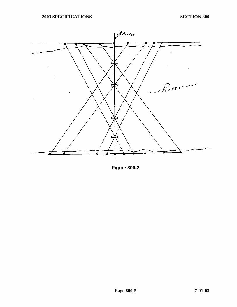
A layout sketch should be made as a permanent field record and all control points should be shown for each structure. This should be done before any construction begins. This will provide a permanent record of the angles, distances, and computations used to establish control points. It will also provide a check to assure the proper stake-out of bridges on curves, skews, etc. Refer to Figures 800-1 and 800-2. It is imperative that everyone concerned is advised of which line is staked at end bents. The information should also be marked clearly on each stake -- Station Number, bridge end, centerline of piling, centerline of cap, etc. All inspection personnel and Contractor's personnel should be informed which line is being used for control. Offset distances should be clearly marked as to which point on the structure the offset distance refers. Good communication between involved parties - Contractor and AHTD - is essential. Accuracy on the stake-out of any major bridge structure is essential. All lines and grades set by field personnel should be cross checked by some independent method. Any method of double checking to assure accuracy of both horizontal and vertical control of plan bridge dimensions may be used as long as it gives the desired results.
800.06 MATERIALS. Control of materials is another of the major responsibilities of the Resident Engineer and his staff. Sampling and testing serve to alert both the Resident Engineer and the Contractor to the need for corrective action in case of nonconformity. For detailed descriptions of inspection of materials, reference should be made to applicable Specifications for individual items. The methods of sampling and testing are described in the Manual of Field Sampling and Testing Procedures. It is essential that the Resident Engineer and his personnel make certain that all materials which are to be incorporated into a bridge structure are tested and approved, with all appropriate reports on file, prior to use.
800.07 RECORDS AND REPORTS. (a) General. Another important duty of the Resident Engineer and his personnel is to keep accurate field records and documentation of construction progress. Matters to be documented should include, but not be limited to:
Normal Progress Reports (including pay quantities). Unusual problems encountered and their solutions. Changes, extra work, and time charges, and their justifications. Results of review of material test reports Unsatisfactory or questionable materials, workmanship, and/or variance
from specifications, contract provisions, or prescribed policies and procedures.
Any controversial matter.
Page 800-3 7-01-03

Figure 800-1
7-01-03 Page 800-4
2003 SPECIFICATIONS SECTION 800
Figure 800-2
Page 800-5 7-01-03
(b) Examples of Records. (1) Diary. This should contain a day by day record of all significant items relating to the project. Since a diary may become important evidence in the resolution of disputes or the establishment of responsibilities or liabilities, it is essential that the notes be complete. Some of the items to be noted in the diary are:
Weather and working conditions (GOOD or POOR) Instructions given the Contractor Important discussions with the Contractor or his representative Official visitors and inspections Work or materials rejected and reasons Time of stopping or resuming work and explanations (i.e., "rained
out at 2:30", "equipment breakdown at noon", etc.) Work done by Contractor's forces during day General purpose of work Length and cause of any delays Contractor equipment inventory (at least once a week) Arrival and departure of major equipment Record of telephone calls Unusual conditions, if any, such as high water, bridge failures,
slides, etc. Progress of stakeout and surveys made (Engineering Activities) Daily Stream Elevations, if applicable
(2) Photographs. Photographs should be taken of complex, unusual, and difficult types of construction, equipment, or conditions from which controversy might be expected to develop, experimental procedures, and other items of special interest. Prints should be labeled, including the date taken and the initials of the person taking the picture.
(3) Recurring Reports. Recurring reports are those involved in preparing estimates (RWP’s, etc.) and the various test reports required.
(c) Bridge Books. There are certain records that are required to be maintained in the Resident Engineer's permanent job files. Among these are: measurements of reinforcing steel cover and deck thickness, beam and deck profiles, the results of holes drilled in the bottom of spread footing excavations, etc. It is recommended that these records be made in a field book rather than on separate sheets of paper. The book may also be used to record the layout sketches, a list and description of benchmarks, level notes, and other similar
7-01-03 Page 800-6

2003 SPECIFICATIONS SECTION 800
data. Such a book is NOT an Original Source Document and shall not be used to record quantities or measurements for quantities. 800.08 SAFETY. The Resident Engineer and his staff should adhere to basic safety principles during construction. The following are examples:
(a) Personal Safety. The Resident Engineer and his personnel must use common sense and good safety practices while working around a bridge structure. Some of the normal rules to follow are:
Be very careful of loose clothing which might snag on forms, shear connectors, etc., and possibly cause serious falls.
Be sure of solid footing. Watch for forms which have been temporarily set in place and could easily become dislodged causing injury.
Never Operate Contractor's equipment.
Watch for falling objects and always wear a hard hat. (b) Control of Construction Equipment Crossing Bridges. On all newly constructed bridges, except precast spans, the Engineer should make certain that the deck concrete has obtained the desired strength before allowing any vehicles or significant loads on the structure. Vehicles weighing in excess of legal loads, off the road type hauling equipment, and other illegal highway loads should not be allowed on a new bridge deck without written permission from the Department. Use of equipment with metal wheels or pads should not be permitted on a new bridge deck without protective devices such as planking.
(c) Barricades and Warning Signs. The traveling public should be protected from danger due to construction operations. Adequate barricades and signs should be placed where they are planned and are most effective. If needed, flagers should be provided by the Contractor. There should be no doubt to the traveling public as to when a road is completely closed and where detours are located. When signs and barricades are no longer needed, they should be removed. The plans will normally include a Standard Drawing pertaining to construction signing. This Standard Drawing will indicate the sign type, color, shape and legend. General Notes appearing on this Standard should be read and understood thoroughly.
(d) Contractor Safety. Refer to Section 107.09 of this Manual for a discussion of the specific safety measures the Contractor is required to take.
800.09 CHANGE ORDERS AND MISCELLANEOUS. (a) Change Orders or Alterations of Quantities. Change Orders are generally required when one or more of the following is involved:
Change in specifications or design. Revision in plans, requiring different materials or altered method
of construction.
Page 800-7 7-01-03
Revision correcting subsurface or site conditions differing materially from those shown on the plans or indicated in the specifications.
Any change involving a revised or new unit price. Any revision involving extra work where extra work is defined as
any work for which there is no contract item. Major Overruns or Underruns.
A full description of the procedures for Change Orders is set forth in Section 104.01 of this Manual.
(b) Cooperation With The Railroad Company. Railroad Grade Separations are special cases of construction that usually have inherent problems requiring cooperation with the railroad company. Some of the problems to be considered are:
Maintenance of safe and uninterrupted operation of trains on schedule.
Methods of excavation for foundations adjacent to railroad tracks. Construction of overhead spans. Construction of temporary trestles. Highway-Railroad agreement requirements (usually a special
provision). Portion of work to be done by Railroad Company.
(c) Final Clean Up. Before a project is accepted, the Resident Engineer and his staff must not only be satisfied with the individual construction items, but also should be satisfied that the Contractor has complied with other contractual requirements. Among these are:
All exposed form work has been stripped and false work removed, including false work piling.
Proper drainage has been achieved on horizontal surfaces (deck slabs and bridge seats).
Any concrete surface patching required has been done using approved materials and methods.
The ground surface has been restored to original lines or graded in accordance with plans.
Abandoned masonry has been disposed of as approved by the Resident Engineer.
Sheet piling and other cofferdam materials have been pulled or cut off below ground line.
Detour bridge pilings have been pulled or cut below ground line.
7-01-03 Page 800-8
2003 SPECIFICATIONS SECTION 800
Shoulders and side slopes of approach fills have been dressed and sloped to drain.
If applicable, all anchor bolts have been grouted in and the tops of piers cleaned of debris.
Unpainted areas have been touched up. Rubbish, old form lumber, and other waste material have been
removed from the project. All stream channels have been cleared of masonry and other
obstructions. Adjacent property, public utility lines, fences, etc., damaged or
disturbed by the Contractor during construction have been acceptably repaired.
Property occupied by Contractor during construction has been left in a satisfactory condition.
ALL final (permanent) stabilization measures have been installed and are functioning in accordance with applicable NPDES and/or 404 Permits. (This includes riprap, seeding, etc.)
Page 800-9 7-01-03

THIS PAGE INTENTIONALLY LEFT BLANK
7-01-03 Page 800-10

2003 SPECIFICATIONS SECTION 801
SECTION 801 EXCAVATION AND BACKFILLING
801.01 GENERAL. Work under this Specification includes the removal of material for the purpose of constructing structures and the backfilling of structures as necessary. This includes dewatering, cofferdam construction and removal, shoring, etc., if necessary, along with disposal of excess material.
Excavation for structures is one of the most critical steps in bridge construction. Since subsurface conditions are occasionally different from those shown on plans, excavation should be observed carefully so that needed changes may be ordered in a timely manner. Conditions that do not agree with the plans and Special Provisions should be reported to the District Engineer.
(a) Preparation Of Foundations. (1) General. Stability is the key to a good foundation. The condition and type of soil or rock should be noted. Dense sands and gravels are good. Clays are generally acceptable. Muck and soft clays should be removed. Rock is satisfactory if sound. Sedimentary rock types may have voids and should be investigated. The Resident Engineer should advise the District Engineer if, in a given footing, there are large differences in types of soils, or a combination of soil and rock. The size of excavation should permit the placing of full width and length of footing.
When pile driving liquefies soft soil, additional excavation with stable backfill may be required. Excavation may also affect nearby buildings, utilities, bridge substructure units, or sloping ground surfaces. The stability of the sides of an excavation depends on the slope of the sides, the depth of the cut, and the character of the material. It may be necessary to modify adjacent slopes or support the sides of excavation.
(2) Rock in Foundation Excavation. Excavation in rock shall be made to neat line of footing. When the use of explosives has been approved by the Engineer, care shall be exercised to avoid shattering rock faces by excessive blasting. All seams shall be cleaned out and filled with concrete mortar or grout. No allowance will be made for over-breakage beyond vertical planes parallel to and 4" (100mm) outside the footing.
The specifications require that bearing areas in bridge footings be checked to verify that a solid stratum of rock exists. This is to be done by drilling one hole for each 50square feet (5 square meters) or less of bearing area. This hole is to be 1 ½ inches (35 mm) or more in diameter and shall be drilled to a minimum depth of 5’ (1.5 m). When the Contractor does this, it should be documented. If this procedure fails to verify the existence of sound material beneath the footing, the footing may have to be lowered and the test holes redrilled.
When other conditions stated in the plans are met and a sound rock stratum is encountered before reaching the elevation shown on the plans and the Resident Engineer, with the concurrence of the Construction Office, determines that this elevation is acceptable; then the Contractor may request in writing that excavation be stopped at this elevation. The Contractor’s letter shall state that a reduction in plan quantity for Unclassified Excavation for Structures-Bridge and Class S Concrete is agreed to by the
Page 800-11 7-01-03

Contractor. In the absence of such written request and agreement, all excavation shall continue to plan elevation.
If the stratum of rock into which the excavation is made varies significantly from the way it is shown on the plans (i.e., sloping severely, elevation higher or lower than shown, unstable, etc.) the Resident Engineer should advise the District Engineer and then contact the Construction Office for guidance. At that time, a decision will be made as to the appropriateness of lengthening stems or thickening footings, along with the amount of payment to the Contractor. If there is no written correspondence on this, the Resident Engineer should record this decision in the Construction Diary.
(3) Water in Foundation Excavation. Ground water level, the level below which all soils are saturated, is often met above the desired foundation level. This water must be prevented from adversely influencing the stability of the slopes and the bearing capacity of the soils. It may be necessary to dewater the site with well points or with shoring or cofferdam construction and pumping. Sumps may be used to drain the excavation if the water flow does not have damaging influence.
(4) Shoring. Shoring refers to temporary support of the sides of an excavation and adjacent facilities. It is a wall type structure, constructed of timber or steel, and installed as the excavation proceeds. The shoring is supported by bracing, often aided by utilizing toe support in the soils. If the excavation is narrow, it is often practical to brace the opposite sides of the shoring against each other. Where the width of excavation precludes this, the shoring may be braced by horizontal walls supported by angled rakers or by tie backs utilizing anchor deadmen outside the excavated area. Shoring should be strong and relatively stiff.
(b) Cofferdams. (1) General. A cofferdam is a form of shoring. It is a structure, generally of a temporary nature, constructed for the purpose of keeping water and earth out of the excavated foundation area. A cofferdam is normally constructed before excavation is started. One type of cofferdam is a box-like enclosure of sheet piling within which the excavation is made, pumped dry if water is encountered, and within which the foundation is constructed. Bracing inside a cofferdam and the flexural strength of cofferdam walls are utilized in the design of the facility to resist the forces applied by the soil and water outside the cofferdam. Cofferdams must be of sufficient size to allow the necessary footing forms, drainage details such as sump holes, clearance for batter piles, and clearance for minor deviations that may occur in installing the walls.
(2) Details Required. For substructure work, the Contractor shall submit to the Resident Engineer details (prepared and/or approved and certified by a Registered [Arkansas] Professional Engineer) showing his proposed design for cofferdam construction. These drawings are submitted to the Resident Engineer for informational purposes and shall include all dimensions needed. Once the Resident Engineer is satisfied as to the completeness of these drawings, the Contractor may proceed with the work. These documents are to be retained in the Resident Engineer's Office in accordance with Subsection 123.10 of this Manual. The Contractor is responsible for the results obtained from the use of the cofferdam design. The AHTD normally will not check cofferdam design. However, the Resident Engineer should verify that the cofferdam is constructed in accordance with the plans submitted.
7-01-03 Page 800-12

2003 SPECIFICATIONS SECTION 801
For work adjacent to railroads, details showing proposed shoring or cofferdam design must be approved by the appropriate railroad and an approved copy furnished to the Resident Engineer prior to its use.
(3) Seal Concrete. It is generally desirable to construct a foundation in the dry. If the cofferdam can simply be pumped dry, this method should be used. If the head of water outside the cofferdam is high and the soil conditions do not permit a dry area, then a concrete seal is used. The seal will function, by virtue of its weight, as an aid in off-setting the unbalanced pressures caused by the difference in water levels between the inside and outside of the cofferdam. Other influencing factors in seal design are weight of soil mass below the seal and confined within the cofferdam, pile anchorage in the soil, bond of piles to the concrete seal, and bond between the seal and the walls of the cofferdam. The walls of the cofferdam should be as watertight as possible.
Generally, the construction of a seal is as follows:
The excavation is made, allowing the water inside the cofferdam to be at the same level as the water outside. When the desired depth is reached, the excavation is stopped and the hole cleaned and shaped. If piles are to be used, they are then driven. The seal concrete is carefully placed under water using the tremie method. After the concrete has set and gained its strength, the cofferdam is dewatered. The surface is leveled, cleaned, and laitance removed. The pile cap or foundation footing is then constructed in the dry.
(c) Pumping - Footings Without Seals. Pumping which permits water flowing in contact with fresh unset concrete should not be permitted, since water flow could wash out cement. The sump from which water is pumped should be outside the footing forms.
(d) Backfill. Backfill includes road approach fill on either side of structures as well as fill around piers and abutments. The key to a stable backfill is the use of good materials properly placed. Constant inspection is essential. Also, 404 Permit restrictions may be a factor.
(1) Materials. The most desirable materials for this purpose are well graded, broken stone, gravel, and sand. These materials have high shearing resistance and drain well. Their behavior is predictable. It is desirable that this type of material be used, if at all possible.
(2) Placement. Importance of proper placing of backfill cannot be overemphasized. Care should be given to the sequence and method of placing.
The proper sequence of placing backfill is covered in the specifications. Reference is made to Subsection 801.08 of the Standard Specifications and to Standard Drawing No 1888A concerning backfilling. Approach fills are made first. For certain types of bridges (box culvert and rigid frames), both abutments are to be backfilled simultaneously. Backfill elevations should be uniform in height as they go up. This should also be done with piers and wing walls. Backfilling should be delayed to permit concrete to acquire strength. There should be no soft zones or voids. Compaction is to be done by equipment designed for the work. For compaction close to a structure, approved mechanical tampers are necessary. A crawler tractor is not a mechanical
Page 800-13 7-01-03

tamper. Density tests should be made on all backfills as well as existing approaches that have been made before construction.
NOTE: The Department performs acceptance testing on this backfill.
(3) Backfills for Weepholes. Backfill for weepholes should permit water to flow out from them, since accumulated water will cause undesirable pressure. The backfill material should be clean and course. Clay and dirt will obstruct the flow of water. Weepholes should be kept clear of all obstructions as the fill is placed, and remain clear after the fill is completed.
801.02 METHOD OF MEASUREMENT. All the various structural excavation pay items covered under this Specification are measured by the Cubic Yard (Cubic Meter). Quantities shown on the plans are to be considered as final, unless exceptions (overruns and/or underruns) are noted.
“Cofferdam” is measured by the unit (Each).
When exceptions are noted, and when it is necessary to lower a bridge footing elevation, the Resident Engineer should adjust the actual volumes of material excavated in accordance with Subsection 801.10 of the Specifications.
NOTE: If it is necessary to excavate a bridge footing to a depth deeper than 7’ (2 m) below plan grade, an "adjustment factor" must be negotiated with the Contractor. Once the Resident Engineer and the Contractor determine a factor that they consider reflects equitable compensation for the work, the Resident Engineer will submit a Change Order establishing this adjustment factor in accordance with the Change Coordination Guidelines found in Subsection 104 of this Manual. This Change Order would normally also document any concrete and reinforcing steel overruns that result from lowering the footing. The Staff Construction Engineer, along with the Bridge Design Division, will work closely with the Resident Engineer to ensure the appropriateness of a change such as this. When field measurement of excavation is required for R. C. Box Culverts, the forms shown in Appendix II, along with the Structural Excavation Book (available from Contract Estimates Section) and the Standard Drawings, should be used to compute the quantity. When field measurement of excavation is required for bridges, Form 19-160 may be used for the sketches and calculations. (See Appendix II.)
NOTE: Undercut of Reinforced Concrete Box Culverts that has been authorized for pay by the Resident Engineer is NOT paid as “______ Excavation for Structures- Roadway”. This excavation is to be measured and paid in accordance with Section 207 (Stone Backfill) or Section 210 (Excavation and Embankment) of the Specifications, as appropriate.
801.03 DOCUMENTATION - CURRENT ESTIMATES. Current Estimate documentation for these items shall be a properly completed Report of Work Performed (RWP) marked "Current Estimate". The "Basis of Estimate" normally will be an estimated percentage of work completed and/or reference to the appropriate "Final Document" RWP. Other methods may be used as long as the method is understandable, accurate, and clearly stated on the RWP.
7-01-03 Page 800-14

2003 SPECIFICATIONS SECTION 801
801.04 DOCUMENTATION - FINAL ESTIMATES. Final Estimate documentation for structural excavation items is to be based on plan quantity and noted variations. The Original Source Document (OSD) that must accompany the Final Estimate is the RWP marked "Final Document".
If there are no variations in plan quantity on a structural excavation item, plan quantity shall be shown on the "Final Document" RWP (OSD) with "Verified Plan Quantity" as the "Basis of Estimate".
When the final pay quantity differs from plan quantity, the "Final Document" RWP(s) should state "Verified Plan Quantity with Field Measured Additions/Deletions" (or similar notation) as the "Basis of Estimate". The variations in plan quantity should be documented by one or both of the following methods:
(a) By field measurements, sketches, and computations entered on or attached to the "Report of Work Performed" form(s), and/or
(b) By reporting the appropriate quantity and referring to the applicable approved Change Order(s) on an RWP marked "Final Document". The measurements, sketches, and calculations must be shown on the Change Order.
Examples of properly completed RWP's for Current and Final Estimate Documentation of structural excavation items are shown in Figures 801-1 and 801-2. Additional information on the completion of RWP's is found in Subsection 109.02 of this Manual. RWP's marked "Current Estimate" should not be submitted with the Final Estimate.
Final Estimate documentation for this “Cofferdam” shall be a properly completed RWP marked "Final Document". The "Basis of Estimate" for this item should be "Actual Field Count". This count should be contained on this RWP.
Page 800-15 7-01-03
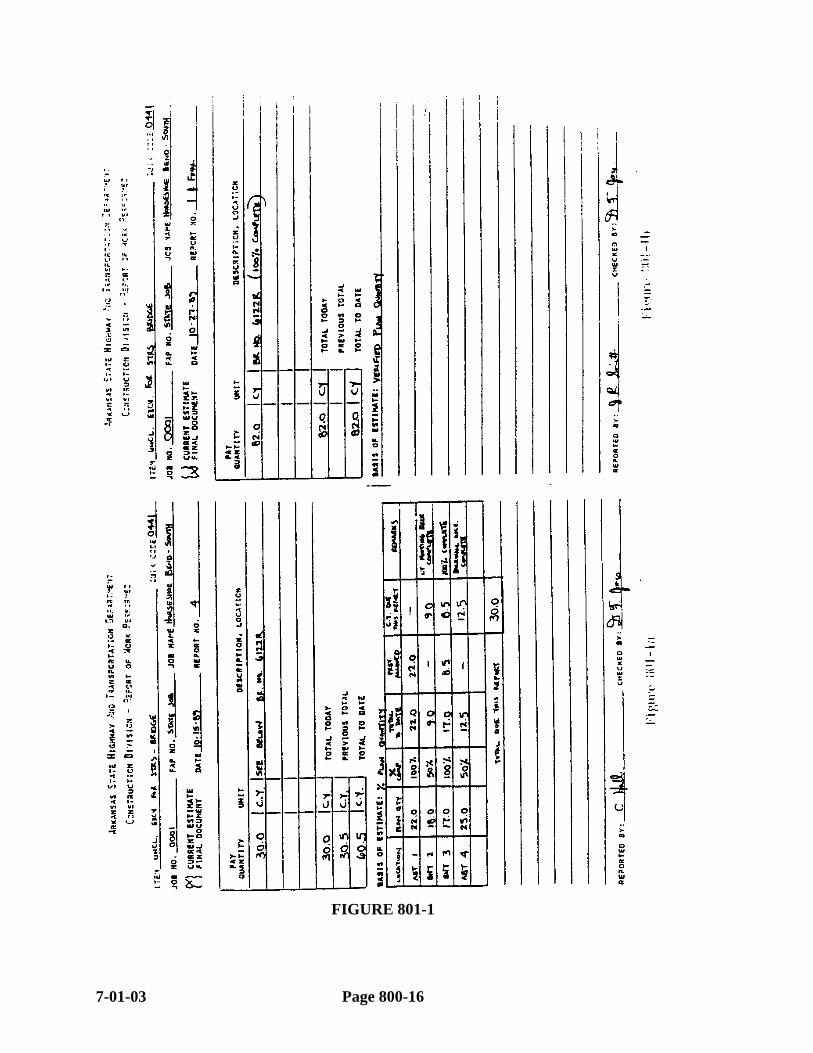
FIGURE 801-1
7-01-03 Page 800-16

2003 SPECIFICATIONS SECTION 801
FIGURE 801-2
Page 800-17 7-01-03
SECTION 802 CONCRETE FOR STRUCTURES
802.01 GENERAL. This specification deals with concrete in bridges, culverts, and miscellaneous structures. It is very detailed in its requirements for structural concrete and should be used as a reference to answer questions as they arise in this area.
Among the requirements which the Resident Engineer must perform and/or enforce are:
(a) Control Of Materials. Subsections 802.02 through 802.08 of the Specifications detail the requirements for the materials used in concrete and the required handling and proportioning requirements. This and the Manual of Field Sampling and Testing Procedures should be used as references to ensure that all requirements are met. The Resident Engineer should also note:
The Resident Engineer may approve the use of retarder and other admixtures as appropriate. All admixtures approved must be compatible with each other.
Documentation that Cement, Flyash, Air Entrainment Agent, Retarder, Curing Compound, etc., used comply with the applicable Specifications must be maintained in accordance with the Manual of Field Sampling and Testing Procedures. (If an admixture is not on the “Qualified Products List", refer to the Manual of Field Sampling and Testing Procedures.)
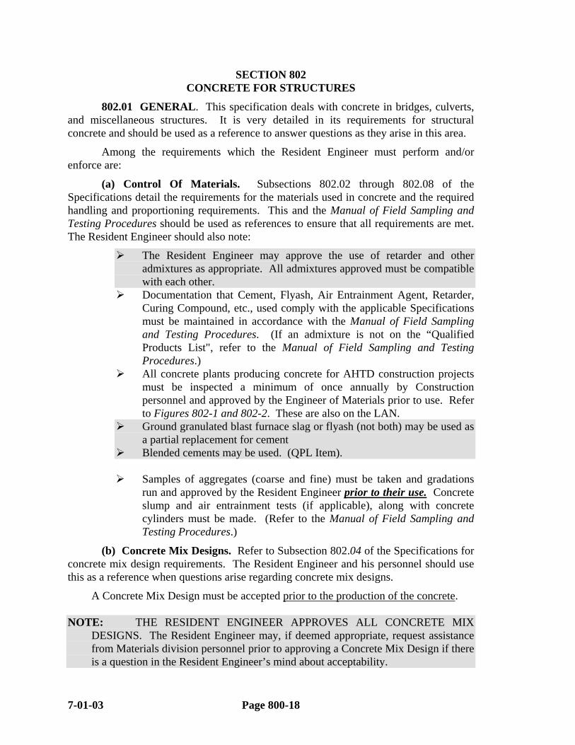
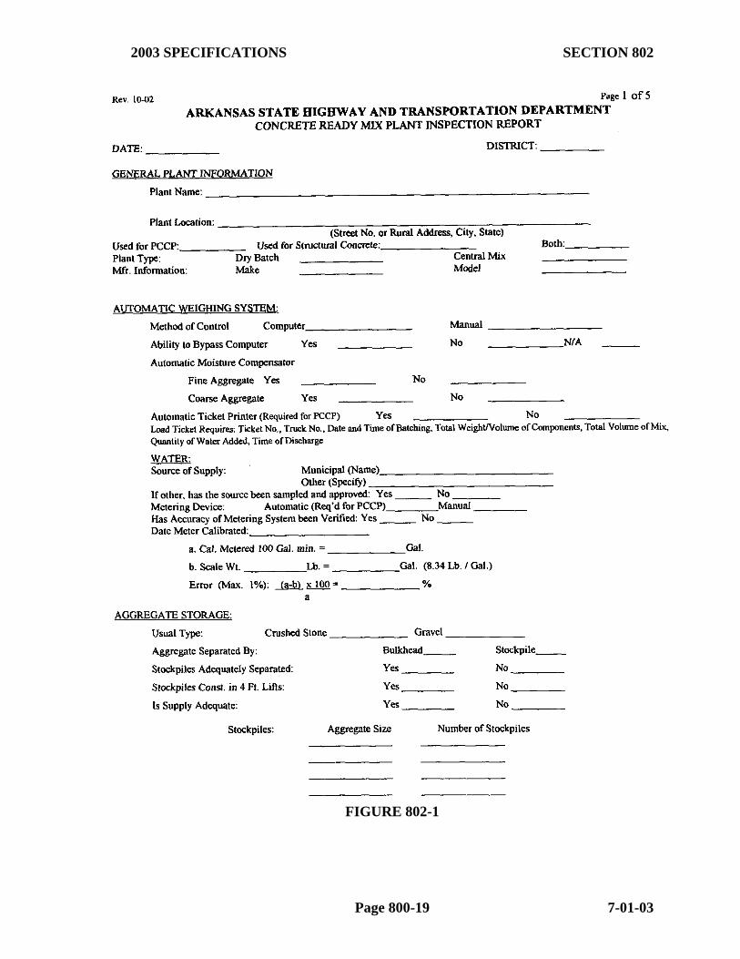
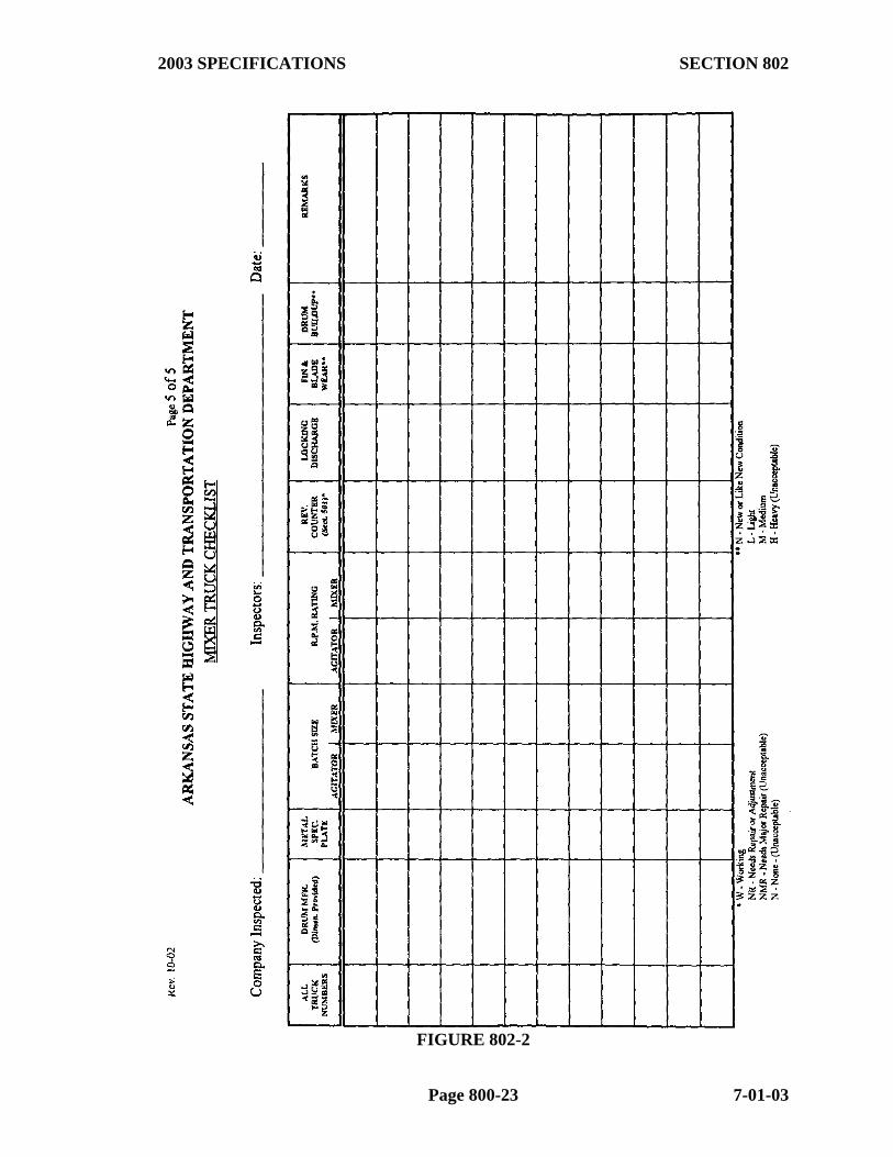
All concrete plants producing concrete for AHTD construction projects must be inspected a minimum of once annually by Construction personnel and approved by the Engineer of Materials prior to use. Refer to Figures 802-1 and 802-2. These are also on the LAN.
Ground granulated blast furnace slag or flyash (not both) may be used as a partial replacement for cement
Blended cements may be used. (QPL Item).
Samples of aggregates (coarse and fine) must be taken and gradations run and approved by the Resident Engineer prior to their use. Concrete slump and air entrainment tests (if applicable), along with concrete cylinders must be made. (Refer to the Manual of Field Sampling and Testing Procedures.)
(b) Concrete Mix Designs. Refer to Subsection 802.04 of the Specifications for concrete mix design requirements. The Resident Engineer and his personnel should use this as a reference when questions arise regarding concrete mix designs.
A Concrete Mix Design must be accepted prior to the production of the concrete. NOTE: THE RESIDENT ENGINEER APPROVES ALL CONCRETE MIX
DESIGNS. The Resident Engineer may, if deemed appropriate, request assistance from Materials division personnel prior to approving a Concrete Mix Design if there is a question in the Resident Engineer’s mind about acceptability.
7-01-03 Page 800-18
2003 SPECIFICATIONS SECTION 802
FIGURE 802-1
Page 800-19 7-01-03
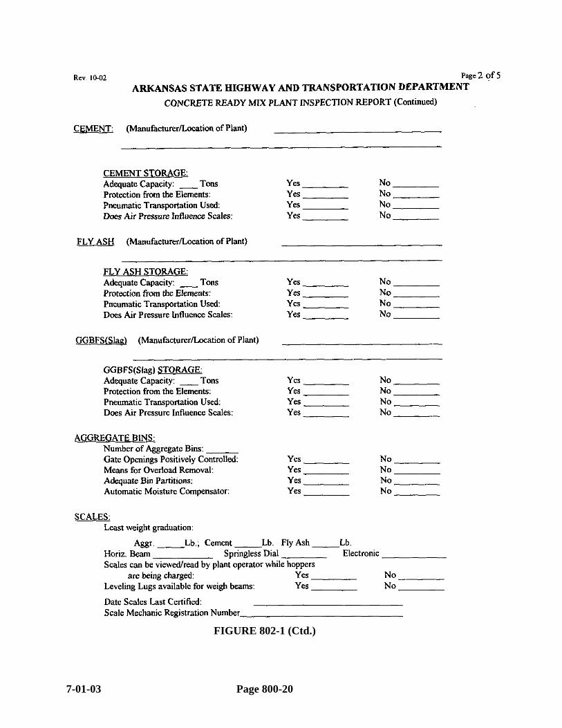
FIGURE 802-1 (Ctd.)
7-01-03 Page 800-20

2003 SPECIFICATIONS SECTION 802
Page 800-21 7-01-03

FIGURE 802-1 (Ctd.)
7-01-03 Page 800-22
2003 SPECIFICATIONS SECTION 802
FIGURE 802-2
Page 800-23 7-01-03
(c) Mixing Concrete. Subsection 802.08 of the Specifications should be used as a reference concerning requirements for concrete plants and the mixing of concrete.
In addition, the Resident Engineer should note the following: It is not necessary for the Resident Engineer to have a Concrete Plant
Inspector present when concrete is batched. The Resident Engineer may, however, provide intermittent or random concrete batching inspection as deemed necessary to verify that it is being batched in accordance with the specifications.
Resident Engineer personnel do NOT advise Contractor or Concrete Plant personnel as to the amounts of additives such as retarder and air entrainment agent.
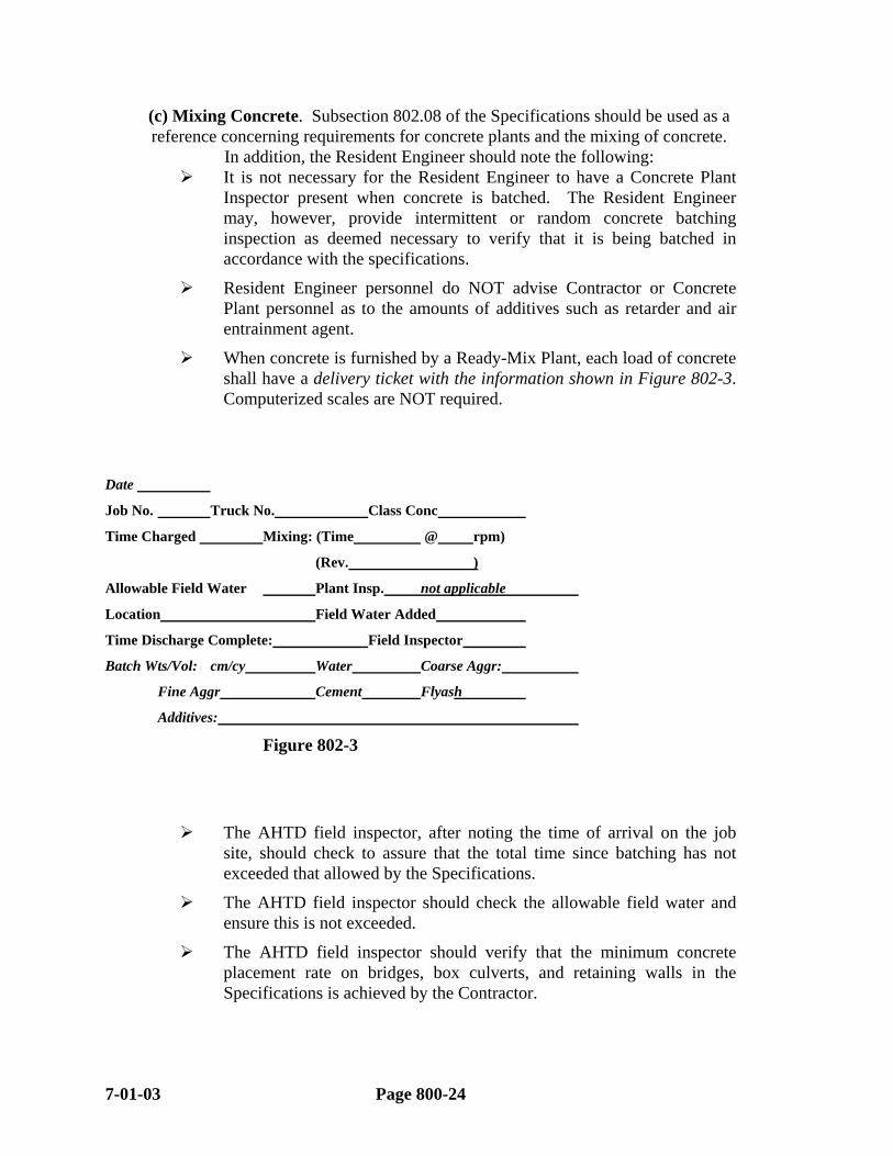
When concrete is furnished by a Ready-Mix Plant, each load of concrete shall have a delivery ticket with the information shown in Figure 802-3. Computerized scales are NOT required.
Date
Job No. Truck No. Class Conc
Time Charged Mixing: (Time @ rpm)
(Rev. )
Allowable Field Water Plant Insp. not applicable
Location Field Water Added
Time Discharge Complete: Field Inspector
Batch Wts/Vol: cm/cy Water Coarse Aggr:
Fine Aggr Cement Flyash
Additives:
Figure 802-3
The AHTD field inspector, after noting the time of arrival on the job site, should check to assure that the total time since batching has not exceeded that allowed by the Specifications.
The AHTD field inspector should check the allowable field water and ensure this is not exceeded.
The AHTD field inspector should verify that the minimum concrete placement rate on bridges, box culverts, and retaining walls in the Specifications is achieved by the Contractor.
7-01-03 Page 800-24

2003 SPECIFICATIONS SECTION 802
(d) Handling And Placing Concrete. The temperature of plastic concrete shall be checked as necessary to ensure compliance with the specifications.
During the placing of the concrete, the inspector should observe the consistency of the concrete and the methods used by the Contractor to spread and work the concrete. Segregation must be avoided, the finished product must be well consolidated, and the monolithic mass of concrete should be free from surface cavities resulting from the trap-ping of air and water bubbles.
"Sand Streaking" must also be avoided. This is usually the result of leaky forms permitting the escape of cement paste. Forms should be watched closely and any leak discovered should be corrected immediately.
Generally, concrete shall be placed in horizontal layers not more than 0.5 m (18") thick and vibrated thoroughly prior to placement of the next layer. If concrete is to be dropped over 1.5 m (5’), it must be deposited through approved pipes ("tremies"). The latter is waived if concrete is to be placed into a wall less than 250 mm (10") thick and nonsegregated concrete is obtained. Concrete should not be dumped indiscriminately through the reinforcement, nor should it be deposited continuously at one point and forced to flow for considerable distances. The Contractor should start at one point and work from that point by dumping succeeding batches in such a way that the concrete will flow along and under the reinforcement and will be vibrated into the preceding batch.
The Specifications require concrete to be consolidated immediately after dumping. The concrete must not be forced to flow to distant points by vibration. The vibrator must be moved continuously since overvibrating any area will cause segregation. It should be applied to the concrete systematically at short intervals so that the vibrated areas of concrete overlap and should be inserted vertically into the full depth of the concrete lift and into any previously placed concrete which has not taken its initial set.
It is sometimes practically impossible to remove all the water from within the forms in foundation work. In such a case, it is best to start the placing of the concrete in one corner of the forms and continue until the concrete is well above the surface of the water, permitting the concrete to displace the water as it moves forward with as little manual disturbance as possible. Vibrators should be used cautiously, well away from any water. Water pumping should be limited to keeping the water level below the concrete level. Action of water pumping should not cause cement to separate from concrete. Concrete should never be deposited in running water.
(e) Depositing Concrete Under Water. Concrete should not be placed in water (unless shown on the plans) without the written permission of the Engineer. The granting of permission to deposit concrete under water should be limited to those cases where it is not practical to dewater cofferdams without the use of concrete seals.
A tremie must be used to place seal concrete, and the Specifications require that it shall be charged sufficiently at all times. If the tremie should lose its charge it must be lifted clear of the water and recharged in the same manner as that required by specifications before starting work. The Contractor should be required to provide enough tremies to place the seal with a minimum of recharging of any tremie.
Page 800-25 7-01-03
(f) Falsework And Forms. Falsework may be supported on either mud sills or piles, depending on the load carrying capacity of the underlying material. Mud sills should be used only on firm material that is not likely to scour or whose bearing capacity will not appreciably change with a change in moisture content. Piles must be driven to an adequate bearing capacity as determined by an approved dynamic pile formula. The elevation of the pile tip must be well below any strata that is likely to scour.
Bracing of falsework should be checked for its adequacy to resist appreciable movement from the forces of moving water or eccentric loading while the forms are being filled.
All timber used in the falsework should be sufficiently seasoned to hold warping and shrinkage to a minimum.
The Contractor shall submit to the Resident Engineer details showing his proposed design of falsework construction for bridge span and overhang support systems. These drawings shall include all dimensions and material information and must have been prepared and/or approved by a Registered Professional Engineer (registered in Arkansas). They are submitted to the Resident Engineer for informational purposes. (The Contractor must maintain copies of design calculations until the project is accepted.) Once the Resident Engineer is satisfied as to the completeness of these drawings, the Contractor may proceed with the work. These documents are to be retained in the Resident Engineer's Office in accordance with Subsection 123.10 of this Manual.
The Contractor is responsible for the results obtained from the use of the falsework design. The AHTD normally will not check the design; however, the Resident Engineer should verify that the falsework is constructed in accordance with the plans submitted.
If permanent steel deck forms are required on the plans or are proposed for use by the Contractor on a bridge deck, detailed plans of the forms must be submitted by the Contractor (or his supplier) to the Bridge Design Engineer. After review, approved plans are sent by Bridge Design Division to the Resident Engineer, the Contractor, and other parties as appropriate. Once approval is obtained, the Contractor may proceed with the work. (If the Contractor submits these to the Resident Engineer, they should be forwarded to the Construction Office.)
(g) Forms. Before placing any concrete, the forms must be completely checked by the Resident Engineer’s inspector for conformance with the plans and specifications, and all irregularities corrected. They should be checked for ease of removal without injury to the concrete.
All sawdust, dirt, and other foreign material, including ponded water, must be removed from within the forms before placing concrete. If the forms are too deep to permit easy removal at the top, an opening should be left at the bottom through which this material can be removed. This opening must be closed and made mortar tight after the forms have been cleaned. Forms should be oiled before placing of reinforcing steel to avoid splashing oil on the steel.
7-01-03 Page 800-26
2003 SPECIFICATIONS SECTION 802
(h) Removal of Falsework, Forms, And Housing. The Specifications state the minimum time that falsework must remain in place for different types of structures, if test cylinders are not used as a guide. Accurate day by day records of weather conditions, including high and low temperatures should be used as a guide in determining when the falsework may be safely removed, if test cylinders are not used as a control.
The sequence of removal of falsework must be such that the structure will be gradually subjected to its working stresses. For instance, when removing the falsework from under a cantilevered element, removal must begin at the point furthest from the support and proceed toward the support. In removing the falsework from under a structure that is continuous over its supports, removal should begin near the areas of maximum dead load positive moment and proceed in both directions toward the supports. Arches and rigid frames should be backfilled before removal of centering. .
Extreme care must be taken in removing forms from curbs and railings to avoid damage.
Any honeycomb or damaged areas noted upon removal of the forms should be repaired immediately.
When permanent steel forms are used, the Specifications provide a detailed procedure for checking for voids.
(i) Weather Restrictions. Subsection 802.16 of the Standard Specifications places additional requirements when placing concrete during cold or hot weather.
A retarder shall be used on bridge decks if the air temperature is 85º F (25º C) and rising. If the temperature of bridge deck concrete reaches 85º F (25º C), the Contractor must take action to prevent succeeding batches from exceeding 90º F (32º C). Concrete batches with temperatures exceeding 90º F (32º C) shall be rejected. To prevent curing cracks, the chart in Appendix IX should be used prior to bridge deck pours to determine the effects of temperature and humidity on concrete curing.
With regard to cool weather, the Specifications state that no concrete shall be placed unless the temperature of the concrete is more than 50° F (10º C) when placed. After placement, the Contractor must maintain structural concrete at a minimum temperature of 50° F (10º C) for at least seven (7) days. (These requirements vary for Class B and B(AE) concrete, and the Specification should be referred to when using these classes of concrete.)
It is very important that the temperature of the ingredients of the mix be kept within the limits of the Specifications. If overheated, a flash set may result before the concrete can be properly placed and finished. The inspector should be sure that the Contractor has an adequate labor force and sufficient equipment to properly place and finish the concrete as quickly as possible and that adequate provision has been made to protect the concrete against freezing or overheating before concrete operations are begun.
(j) Curing Concrete For Structures. The proper curing of concrete requires the proper control of three major factors: humidity, temperature, and protection against disturbance. Ideally, concrete should be kept under conditions such as will produce a uniform hydration of the cement at the fastest, most economical and most practical rate.
Page 800-27 7-01-03

The Specifications require that all structural concrete shall be kept continuously moist for a minimum period of seven (7) days and at a minimum temperature of 50° F (10º C). Other concrete must be protected against freezing for seven days. The Specifications also list acceptable materials and methods for curing. Frequent inspections of curing concrete should be made to see that it is kept moist and at the proper temperature. When damp-proofing or water proofing (consisting of mopping of bituminous material, generally to the inside surfaces of abutment breastwall and wing-walls) is a part of the Contract, the use of a membrane curing compound is not permitted, since the asphalt materials will not bond to the concrete because of the membrane.
Where wooden forms are left in place during curing, they should be wetted as necessary to prevent opening cracks that would permit loss of moisture from the concrete.
While the concrete is curing, it must not be subjected to disturbances or loads. Concrete that is disturbed or loaded while partially hydrated may be irreparably damaged.
NOTE: Clear curing compound shall be used as an interim cure for bridge decks and shall be applied immediately after final finishing. Final curing shall be accomplished using mats or blankets which shall be placed as soon as the deck surface will support foot traffic without deformation.
(k) Expansion And Fixed Joints. Joints are to be constructed in accordance with the plans and Specifications. The inspector should ensure that concrete finishers do not plaster over the joint in finishing and that the edges are finished in the manner required. Material used to seal joints should be tested and approved prior to use in accordance with the Manual of Field Sampling and Testing Procedures.
(l) Bearings. Anchor bolts for bearing devices are not always placed when the concrete is cast. If this is the case, applicable options allowed on the plans should be enforced. Also, if holes are left in the concrete into which the anchor bolts will be later grouted, care must be taken to prevent water from collecting in these holes since it might freeze and damage the concrete.
(m) Finishing Concrete Surfaces. The various classes of surface finishes are described in detail in the specifications and should be used as a reference.
Special attention should be given to the following in this portion of the specification:
Surfaces to be patched must be thoroughly saturated with water before patching.
For concrete surfaces requiring a rubbed finish, rubbing shall begin as soon as the forms can be safely removed without danger of injuring the concrete. The surfaces must be thoroughly saturated with water before rubbing begins and kept saturated during rubbing operations.
(n) Bridge Deck Construction. Of all the phases of constructing highway structures, the finishing of the concrete bridge deck demands the most critical attention to ensure that a smooth riding surface is obtained. The preceding paragraphs of
7-01-03 Page 800-28
2003 SPECIFICATIONS SECTION 802
Subsection 802 of this Manual generally apply to bridge deck concrete. For emphasis, certain other factors are treated in greater detail below:
The Resident Engineer’s personnel should thoroughly review the Contractor’s beam and deck form grades as required in Section 636.01 of this Manual. Deck forms should be inspected to insure that the forms are properly set to the proper height above or below the beams to attain the correct deck thickness.
The air content of the concrete should be checked in accordance with the Manual of Field Sampling and Testing Procedures. NOTE: Subsection 802.08 of the Specifications allows the Contractor to add additional air entraining material in the field if the air content is below the air content specified.
To avoid possible cracking in decks, alert inspection is particularly required to note changes in bleeding, workability, and cohesiveness of the concrete. Large variations in mixing time, concrete temperature, aggregate gradation, or mix proportions should not be tolerated.
Excessive slump promotes segregation, shrinkage, and cracking. Slump must be limited to the requirements of Subsection 802.05 of the Standard Specifications (1" - 4" [25 – 100 mm]).
Unbonded horizontal or sloping joints (cold joints) should not be permitted.
In setting screed guides for deck slabs of cast-in-place concrete bridges, deflection from dead load and plastic flow must be considered in addition to the roadway gradient. Sufficient "tattle-tales" should be suspended from the forms to permit a quick and easy determination of actual deflection as the forms are loaded. Any excessive deflection noted must be corrected before the concrete has taken its initial set. Corrections should be made with either double hardwood wedges or screw jacks.
If the deck slab is supported on steel stringers or precast concrete stringers, elevations along the top of the top flanges of the stringers, after they are in their final positions and prior to placement of concrete, must be obtained and any variation from plan elevations noted. Any discrepancies in elevation from plans must be corrected, either by varying the thickness of the slab or the build-down haunch between slab and top flange. Screed guides are then set using the top of the top flanges as datum.
Screed guides may be of either timber or steel and may be placed either longitudinally or transversely. They must be capable of supporting all equipment used in finishing the surface without excessive deflection or lateral movement. If imbedded in the concrete, they must be removed before the concrete has taken its initial set and the area they occupy hand finished. Screeds must be sufficiently rigid to retain their strike-off profiles when freely supported at their ends. They must be provided with a means of adjusting their strike-off profile to conform with the required template. If screeding is to progress longitudinally, a check should be made of the strike-off profile of
Page 800-29 7-01-03
the screed while supported at its ends for conformity with that portion of the roadway template between the screed guides.
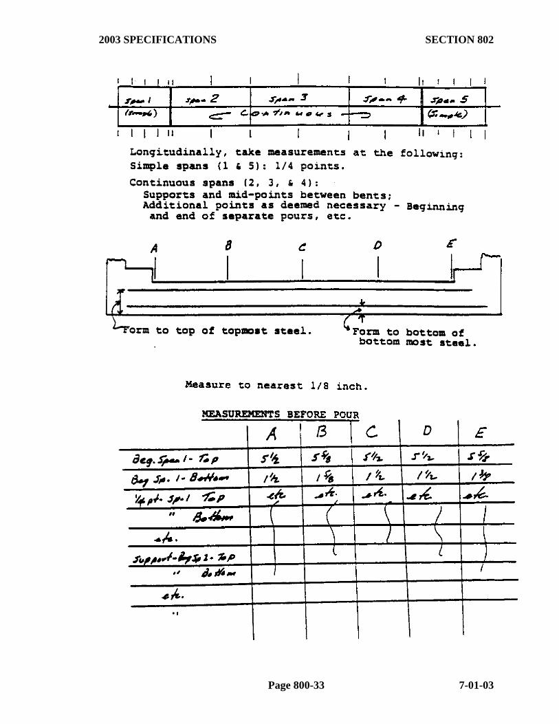
Both before concrete is placed and again after screeding, the deck thickness and the position of the reinforcing steel must be measured and recorded by the AHTD inspector to ensure that the required concrete cover is obtained. This shall be done in accordance with Figures 802-4 and 802-5 and the information retained in the Resident Engineer's job files.
As the screed progresses, it must cut concrete along its full length. Lateral movement should be just sufficient to facilitate forward movement of the screed.
If a longitudinal screed is used, a check should be made to insure that the screed profile conforms to both the vertical curvature of the bridge and the deflection due to the weight of the parapet rail and sidewalk (if applicable). When a longitudinal screed is used, bridge decks are to be poured in such a manner that all of a pour is completed before ANY of the concrete has reached its initial set. Sufficient concrete must be placed ahead of the screed to fully load the beam or girder prior to striking off.
When a transverse screed is used, concrete is to be placed in such a manner that no concrete will reach its initial set closer than 100' (30 m) behind the strike-off. This will generally require the use of an approved retarder.
(o) Bridge Deck Surface Tests. It is imperative that the Contractor adhere to the requirements for floating and straight-edging behind the screed as set out under Subsection 802.21 of the Specifications. Straight-edging must continue across any previously placed concrete sufficiently to ensure that no irregularities will occur at or near the junction of old and new concrete.
After the concrete has set up, the AHTD inspector must check the bridge deck surface as follows:
As soon as the concrete has hardened sufficiently to bear a person's weight without injury to the concrete, and not later than the next morning, the bridge deck surface shall be thoroughly straight-edged both transversely and longitudinally. Any areas not within the limits of the specifications - 3 mm in 1/8" in 10' (3 m) - shall be plainly marked for correction by the Contractor.
At the same time as above, profiles shall be taken at 10' (3 m) intervals along the bridge centerline, lane centerlines, and the gutterlines. This information is plotted and, if these roadway surface profiles vary in excess of 1/4" in 20' (6 mm in 6 m), the Contractor must make appropriate changes in his operation prior to being allowed to pour the next bridge deck.
After the entire bridge superstructure is completed, the AHTD inspector must straight-edge and profile the entire bridge as above. A copy of all plots shall be retained in the Resident Engineer's Office in the same
7-01-03 Page 800-30

2003 SPECIFICATIONS SECTION 802
manner as test reports and certifications. (See Subsection 123.10 of this Manual.)
The Contractor must correct the bridge deck to within the Specification tolerances. Scrabblers are not permitted for this purpose. Any areas ground down must have the tining reestablished by grooving.
NOTE: In addition, a Contractor may at his option (on bridges over 150’ in length) elect to check a Bridge Deck for exceptional smoothness and eligibility for a payment incentive. Refer to Subsection 802.06(d) of the Specifications for details concerning this.
(p) Precast And Prestressed Concrete Products. Precasting and prestressing of members require specialized equipment and normally is done at a central location where the facilities are available. Shop inspection of the manufacturing process of prestressed concrete products outside of Arkansas will be done by an inspection agency working under the direction of the Engineer of Materials.
Inspection of precast and prestressed concrete products is similar in many ways to inspection of conventional concrete construction. However, dimensional tolerances are closer, very low slump concrete is used, and the openings for concrete placement are smaller. The Resident Engineer should use Subsections 802.21 and 802.22 of the Specifications as a reference when involved in the inspection of precast and/or prestressed concrete products.
802.02 METHOD OF MEASUREMENT. Concrete is measured by the Cubic Yard (Cubic Meter). No deduction is made for concrete displaced by reinforcing steel, piling, structural steel, chamfers, etc. The quantities shown on the plans shall be considered as final unless exception(s) (plus or minus) are noted.
The plan quantity for Reinforced Concrete Box Culverts should be checked to determine that the volumes for openings for Pipe Culverts, Drop Inlets, Manholes, etc., have been deducted. When field measurement of Concrete is required for Box Culverts, the forms shown in Appendix II, along with the Standard Drawings, should be used to make the calculations. These forms, along with any sketches, should be attached to the RWP marked "Final Document". Whenever the plan quantities are believed to be inaccurate, either by the Resident Engineer or the Contractor, field measurement and calculation should be made. Field conditions usually require some changes on Box Culvert Extensions.
When field measurement of Concrete is required for work other than Box Culverts, Form 19-160 may be used for the sketches and calculations. (See Appendix II.)
NOTE: The Resident Engineer MUST verify that the concrete quantities are accurate prior to the Contractor performing the work. The forms for R. C. Box Culverts Form 19-160 (see Appendix II) may be used for this purpose.
Grooving is measured by the Square Yard (Square Meter).
Precast Reinforced Box Culvert units shall be measured in accordance with Section 607 of the Specifications.
Page 800-31 7-01-03

Precast concrete products are measured by the unit "each" of the size and type specified.
Prestressed Concrete Girders are measured by the Linear Foot (Meter).
802.03 DOCUMENTATION - CURRENT ESTIMATES. Current Estimate Documentation for items under this Specification shall be properly completed RWP's marked "Current Estimate". The "Basis of Estimate" may be based on a percent of plan quantity, reference to the appropriate "Final Document" RWP, approximate field measurement, etc. The method used for "Basis of Payment" must be understandable, accurate, and clearly stated on the RWP.
802.04 DOCUMENTATION - FINAL ESTIMATES. Final Estimate documentation for the various classes of concrete is to be based on plan quantity and noted variations. The Original Source Document (OSD) that must accompany the Final Estimate is the RWP marked "Final Document".
If there are no variations in plan quantity on a concrete item, plan quantity should be shown on the "Final Document" RWP with "Verified Plan Quantity" as the "Basis of Estimate".
When the final pay quantity differs from plan quantity, the "Final Document" RWP(s) should state "Verified Plan Quantity with Field Measured Additions/Deletions" (or similar notation) as the "Basis of Estimate". The variations in plan quantity should be documented by one or more of the following methods:
(1) By field measurements, sketches, and computations entered on or attached to the "Report of Work Performed" forms and/or
(2) By reporting the appropriate quantity and referring to the applicable approved Change Order number on an RWP marked "Final Document". In this case, the Change Order must contain appropriate sketches, measurements, and computations.
Final Estimate documentation for other items covered by this Specification shall also be properly completed RWP's marked "Final Document". The "Basis of Estimate" shall be "Actual Field Measurement" or "Field Count", as applicable. Field Measurements and appropriate calculations or Field Counts shall be shown on the "Final Document" RWP or on attached sheets.
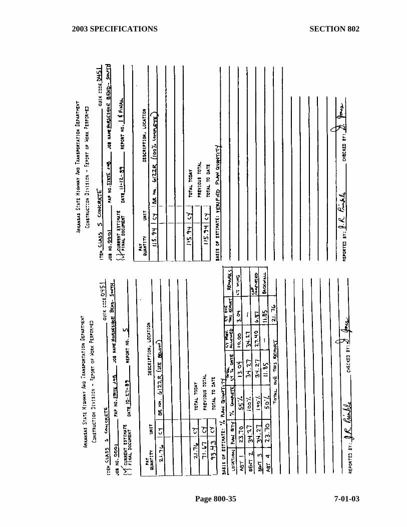
Examples of properly completed RWP's for both Current and Final Estimate Documentation for items covered by this Specification are shown in Figures 802-6 and 802-7. Additional information on the completion of RWP's is found in Subsection 109.02 of this Manual. RWP's marked "Current Estimate" should not be submitted with the Final Estimate.
7-01-03 Page 800-32
2003 SPECIFICATIONS SECTION 802
Page 800-33 7-01-03

FIGURE 802-4
FIGURE 802-5
7-01-03 Page 800-34
2003 SPECIFICATIONS SECTION 802
Page 800-35 7-01-03
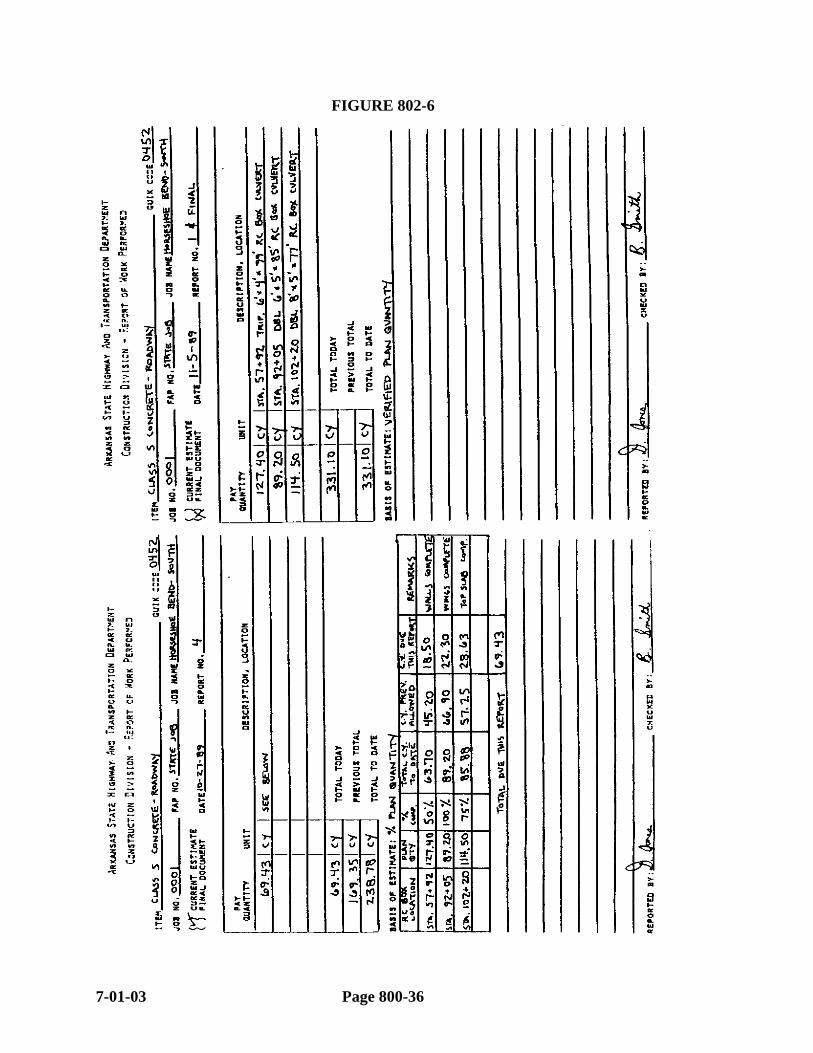
FIGURE 802-6
7-01-03 Page 800-36

2003 SPECIFICATIONS SECTION 802
FIGURE 802-7
Page 800-37 7-01-03
SECTION 803
PROTECTIVE TREATMENT FOR CONCRETE
803.01 GENERAL. This item consists of cleaning, preparing, and treating concrete bridge decks (including curbs, sidewalks, parapets, etc.) with a protective treatment of the class treatment as specified on the plans. This specification should be used as a reference.
803.02 METHOD OF MEASUREMENT. Class 1 Protective Surface Treatment is measured by the Gallon (Liter). Plan quantity is to be considered the final quantity, unless significant variation from it is noted.
Class 2 Protective Surface Treatment is measured by the Square Yard (Square Meter). Plan quantity is to be considered the final quantity, unless significant variation from it is noted.
Class 3 Protective Surface Treatment is measured by the Linear Foot (Meter).
803.03 DOCUMENTATION - CURRENT ESTIMATES. Current Estimate Documentation for this item shall be properly completed RWP's marked "Current Estimate". The "Basis of Estimate" may be based on a percent of plan quantity, reference to the appropriate "Final Document" RWP, approximate field measurement, etc. The method used for "Basis of Payment" must be understandable, accurate, and clearly stated on the RWP.
803.04 DOCUMENTATION - FINAL ESTIMATES. Final Estimate documentation for this item shall be properly completed RWP's marked "Final Document". The "Basis of Estimate" for Class 1 and 2 Protective Treatments should be "Verified Plan Quantity", unless "Actual Field Measurement" is necessary due to a significant variation from the planned amount used. Field Measurement, if deemed necessary, shall be attached to or contained on the "Final Document" RWP. The “Basis of Estimate for Class 3 Protective Treatment shall be “Actual Field Measurement”. The field measurement for this item should be included on the properly completed RWP marked “Final Document.”
Additional information on the completion of RWP's is found in Subsection 109.02 of this Manual. RWP's marked "Current Estimate" should not be submitted with the Final Estimate.
SECTION 804 REINFORCING STEEL FOR STRUCTURES
804.01 GENERAL. All reinforcing steel must be within the limits of the specifications as to size and physical qualities. Test specimens, in conformance with the Manual of Field Sampling and Testing Procedures must be sent to the laboratory from all shipments for which there are no records of previous approval or applicable certifications.
7-01-03 Page 800-38
2003 SPECIFICATIONS SECTION 804
Reinforcing steel should not be stored on the ground. It must not be stored in a manner or in a place where it is likely to be damaged or bent by equipment. Loose mill scale, heavy rust, dirt, grease, or any other deleterious material must be removed before the reinforcement is placed in the forms. If epoxy coated reinforcing steel is to be stored for an extended period of time (i. e., several months) it should be shielded from ultraviolet rays of the sun to prevent deterioration.
All bent bars must be checked for conformity with bending details, including conformance with the planned pin diameters.
If precast mortar blocks are used to hold the reinforcement from the forms, they should be cast with a height equal to the required concrete cover. No side of either face should be greater than 1 1/2 inches. (This is not a Specification requirement, but is good construction practice.)
Prior to placing any concrete in the forms, the reinforcing steel should be checked to see that it conforms with the location and number of bars shown on the plans. Bolsters should be checked closely for proper height and condition. The inspector should ensure that reinforcing steel is securely tied and anchored against any probable displacement by concrete operations.
804.02 METHOD OF MEASUREMENT. Reinforcing steel is measured by the Pound (Kilogram). The quantities shown on the plans shall be considered as final unless exception(s) (plus or minus) are noted.
When field measurement of Reinforcing Steel is required for Box Culverts, the forms shown in Appendix II, along with the Standard Drawings, should be used for the calculations.
NOTE: No deduction is made for Reinforcing Steel displaced by openings for Drop Inlets, Junction Boxes, Pipe, etc.
When field measurement of Reinforcing Steel is required for other than Box Culverts, the weight is calculated using the linear feet determined from the drawings and the weight per Foot (Meter) shown in the Specifications for the type bar involved. Form 19-184 should be used to make these calculations. (See Appendix II.)
804.03 DOCUMENTATION - CURRENT AND FINAL ESTIMATES. Refer to Subsections 802.03 and 802.04 of this Manual. Information contained in it concerning concrete is also applicable to Reinforcing Steel.
NOTE: For Reinforcing Steel, a comparison of invoice weights or supplier's computations should be made at the end of the project as an additional check of plan accuracy.
NOTE: Reinforcing Steel is to be documented and paid after it has been properly placed and tied. It need not be incorporated into the concrete at the time of payment.
Page 800-39 7-01-03

SECTION 805 BEARING PILES
805.01 (a) General. This Section of the Specifications deals with furnishing and driving steel and precast concrete piling in accordance with the plans and Specifications. Pile lengths shown on the plans are for estimating purposes only, unless otherwise specified.
Production pile lengths are normally determined by test pile results and authorized by the Department prior to being ordered by the Contractor. After authorization of pile lengths, the original test pile record will be transmitted to the Construction Office for inclusion into the Master File and a copy will be sent to the Resident Engineer.
The Resident Engineer will notify the Contractor in writing of these lengths. Copies of this letter will be distributed by the Resident Engineer as follows:
Original -- Contractor Copy -- District Engineer Copy -- Construction Office Copy -- RE Job File
A pile is a structural unit that transmits loads into the ground. It does this by frictional resistance along the surface of the pile and/or by direct bearing of the pile tip.
Several field checks should be made before piles are driven. The type, size, condition, and length of the piles furnished should be as shown in plans and specifications, or as determined by Test Pile data. Field information may reveal that the type of pile selected is unsatisfactory. For example, soils of high caustic or acidic nature could induce corrosive electrolytic action on steel piles. The Resident Engineer should confer with the District Engineer if there is reason to believe field conditions may adversely affect the piles.
Planned earthwork – both excavation and/or embankment - should be completed before driving piles in an area. In all instances, it is well to refer to the excavation notes on the plans for any special requirements on the earthwork items in the area piles are to go.
Pre-boring of pilot holes through embankment sections before driving piles may help to eliminate some negative friction and overloading of piles if and when embankment consolidates. Also, it is not unusual for a Contractor to pre-bore holes so that minimum penetration can be obtained before a pile reaches the point of refusal.
Heaving of piles is a common problem in clay soils. This occurs when the volume displaced by the piles is greater than that which the soil embodied within the pile foundation will compact. Re-driving is necessary in this situation.
Pile rebound is another problem that occurs often in some areas. If rebound occurs, it may be impossible to obtain accurate bearing data. Careful observance of driving operations will normally permit the Inspector to take bearing data at the most favorable time.
(b) Materials. Piling must be approved prior to use in accordance with the Manual of Field Sampling and Testing Procedures. Piles must be stored and handled in such a way as to avoid injury to them.
7-01-03 Page 800-38

2003 SPECIFICATIONS SECTION 805
NOTE: Class S(AE) Concrete is used in buildup of precast concrete piling. The Contractor performs QC/QA testing on this.
When test piles are driven, the Engineer will establish order lengths for the remaining piles, based on the results of the test piles. When the plans specify order lengths and test piles are not driven, the specified lengths are the established order lengths. When the plans do not specify order lengths and test piles are not driven, the Contractor is responsible for determining the order lengths.
(c) Pile Driving Equipment. Pile driving equipment should be adequate to handle the sizes of piles for the job. It should be capable of driving piles to the necessary depth and bearing without materially damaging the piles. Heavier piles require heavier equipment. The Specifications require that pile driving equipment comply with the following:
All pile driving equipment except gravity hammers shall utilize hammer cushions in accordance with the hammer manufacturer's guidelines. Wood, wire rope, and asbestos are prohibited.
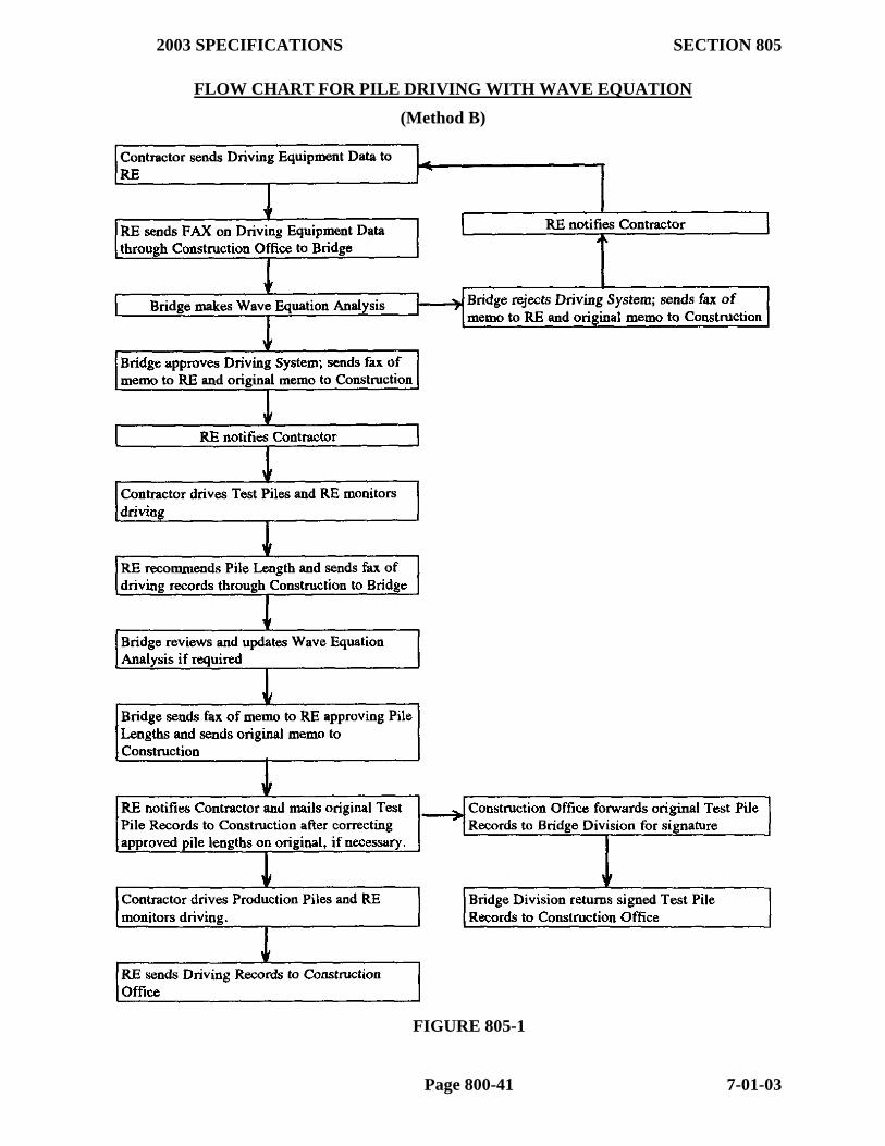
The Contractor shall submit the Pile and Driving Equipment Data Form (Figure 805-2) to the Resident Engineer within the time limits set forth in the Specifications. If Method A (Engineering News Record Formula) is specified to be utilized to compute the bearings on a project, the Resident Engineer shall forward the information to the District Engineer for review. On projects utilizing Method B (Wave Equation Analysis) and Method C (Dynamic Load Test), to compute bearings, this form shall be forwarded to Bridge Division for review and approval of the proposed driving system - see Figure 805-1. This will then be sent to the Construction Office for review by appropriate parties and entered into the Master files. The Pile and Driving Equipment Forms Metric and US versions) are available on the Construction Directory of the LAN, misc. subdirectory (see Appendix IIA).
Subsection 805.07 of the Specifications sets forth various requirements to piling hammers must conform. The Resident Engineer and his inspector should become familiar with this and utilize it as a reference.
NOTE: Manufacturer's information (Specifications) for many single-acting steam/air and diesel pile driving hammers is found in "Hammer Specifications and Bearing Tables for Single-Acting Pile Driving Hammers". This book is available in each Resident Engineer office.
If additional equipment is required to enable the Contractor to drive piling to the required penetration and bearing (such as augers, jets, etc.) it is to be provided by the Contractor at no additional expense to the State, unless otherwise specified in the Plans.
(d) Determination Of Bearing Values. Bearing values of Piling are determined using the method specified in the contract. If a method is not specified, bearing values will be computed using "Empirical Pile Formulas". Methods of computing bearing values include the following:
(1) "Empirical Pile Formulas" (Method A) generally give theoretical safe bearing in pounds. These formulas have been developed to show relationship between driving energies, pile penetration, and dynamic resistance. One of the simplest Page 800-39 7-01-03
and most widely used formulas (and the one used by the Department) is the Engineering News Record Formula, found in Section 805.09(a) of the Specifications. When used in conjunction with Test Piles, the Resident Engineer documents the driving data and bearing value computations on Form 19-166E, "Test Pile Record" (Form 19-166EM for metric projects), and the DISTRICT ENGINEER approves production pile lengths. Both of these forms are available in the Forms subdirectory of the Construction Directory on the LAN (see Appendix IIA for filenames and Appendix III for instructions for completing the forms). The Staff Construction Engineer should be contacted for review and concurrence prior to the District Engineer's authorization of pile lengths if there is significant variance from plan lengths, unusual conditions, etc.
The Resident Engineer documents Production Pile data and bearing value computations on Form 19-167E "Piling Record" (Form 19-167EM for metric projects) (Refer to Appendices II & III of this Manual.)
7-01-03 Page 800-40
2003 SPECIFICATIONS SECTION 805
FLOW CHART FOR PILE DRIVING WITH WAVE EQUATION
(Method B)
FIGURE 805-1
Page 800-41 7-01-03

FIGURE 805-2
7-01-03 Page 800-42
2003 SPECIFICATIONS SECTION 805
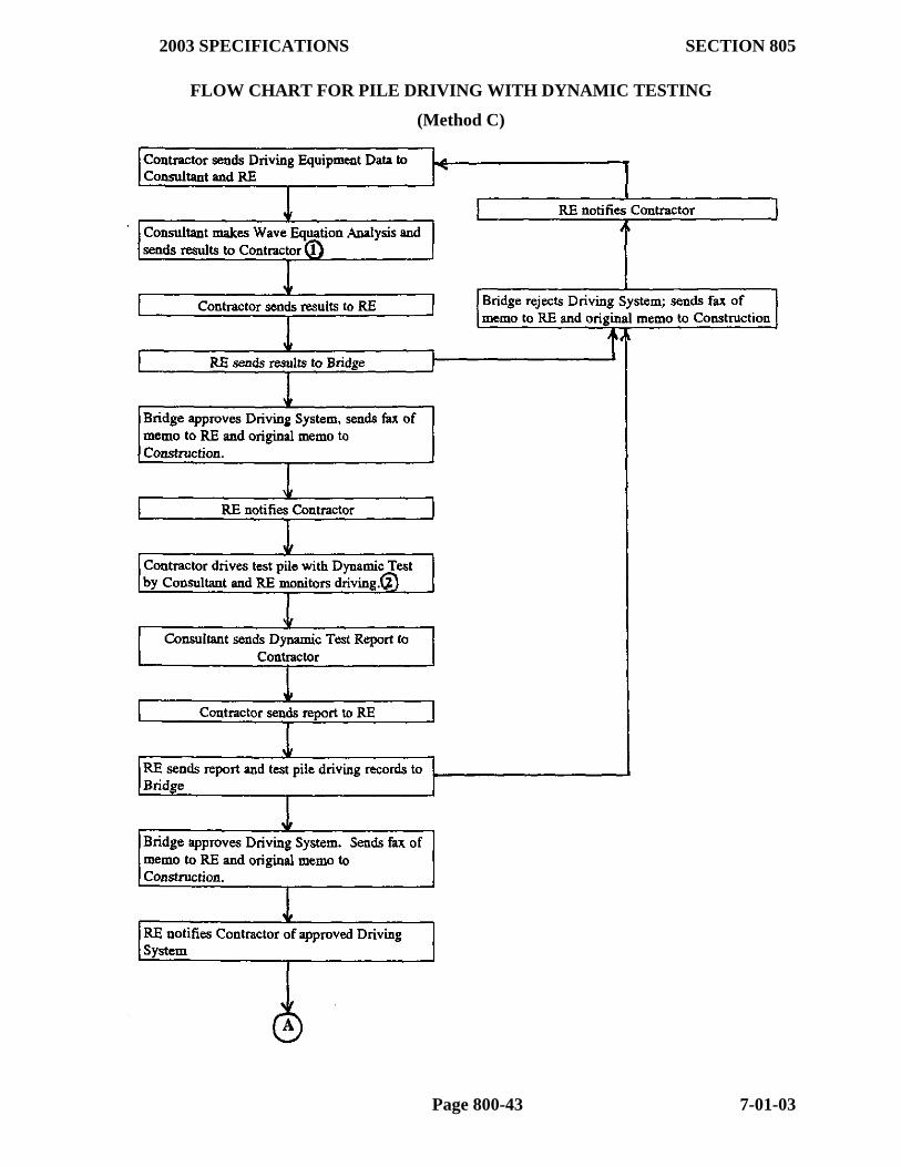
FLOW CHART FOR PILE DRIVING WITH DYNAMIC TESTING
(Method C)
Page 800-43 7-01-03
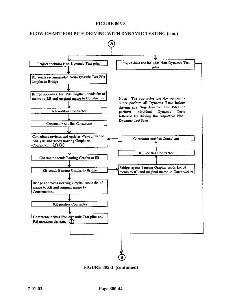
FIGURE 805-3 FLOW CHART FOR PILE DRIVING WITH DYNAMIC TESTING (con.)
FIGURE 805-3 (continued)
7-01-03 Page 800-44
2003 SPECIFICATIONS SECTION 805
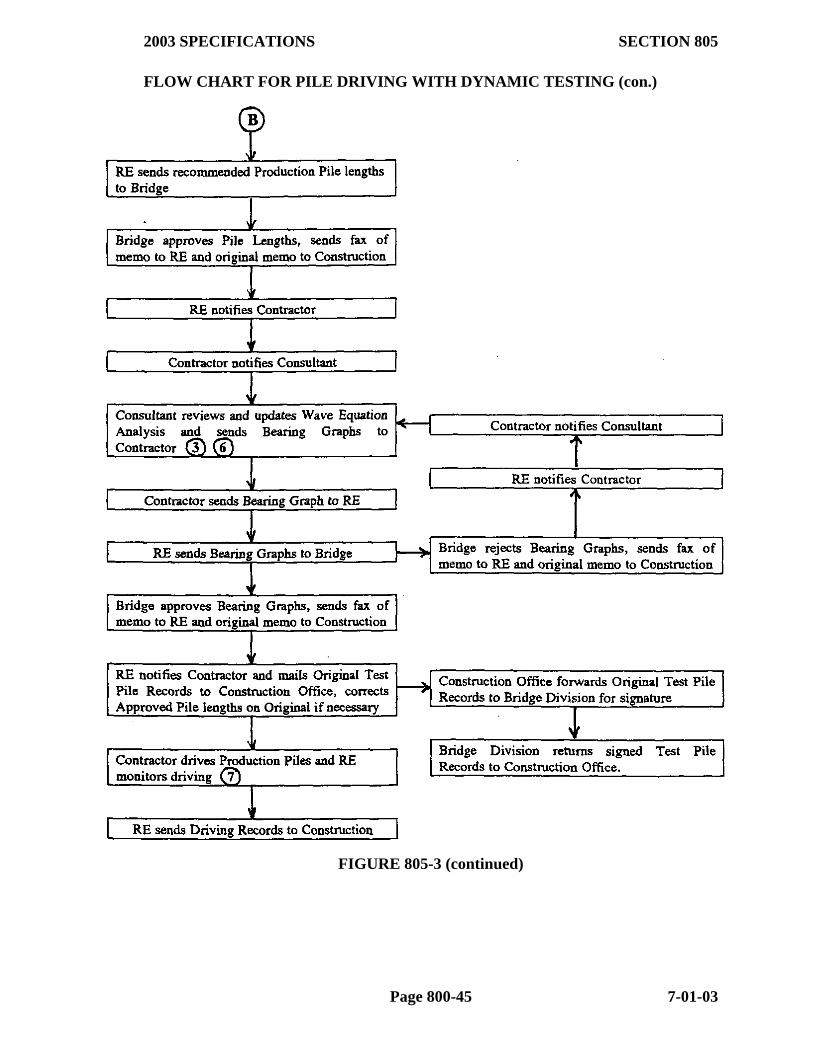
FLOW CHART FOR PILE DRIVING WITH DYNAMIC TESTING (con.)
FIGURE 805-3 (continued)
Page 800-45 7-01-03

Supplemental Information for Dynamic Pile Driving (Refer to Dynamic Pile Flow Chart)
1. Include as part of the information to be sent to Bridge Division a copy of the Driving
Equipment Data Form along with the echo print of input data from the wave equation model. Results of the wave equation analysis shall include the hammer blow count and pile stresses (compressive and tensile) at the required ultimate capacity. Results of a separate wave equation analysis made at a higher ultimate capacity resulting in a hammer blow count of 20 blows per 1 inch (25 mm) shall include pile stresses (compressive and tensile).
2. Drive the test pile with dynamic testing according to the Section 805.09(c)(4) of the Standard Specifications.
3. Use information from the driving records, dynamic test, and CAPWAPC analysis to develop a refined wave equation model. At the capacity indicated by the CAPWAPC analysis, the refined wave equation model shall have a reasonable match with the following field results:
a. Stroke and blow count b. Compressive and tensile pile stresses c. Transferred energy to the pile
Include as part of the information to be sent to Bridge Division the echo print of input data from the refined wave equation model.
4. Use the refined wave equation model to generate bearing graphs to evaluate the ultimate capacity of test piles not requiring dynamic testing. Generate bearing graphs at 100% of the required ultimate capacity shown on the plans. All bearing graphs shall be based upon approved pile lengths. A common bearing graph may be used for multiple bents if a wave equation analysis indicates a negligible difference in the analysis results. Include as part of the information to be sent to Bridge Division the echo print of input data from all wave equation models used to generate bearing graphs.
5. Drive the test pile not requiring dynamic testing according to Section 805.09(c)(7) of the Standard Specifications.
6. Use the refined wave equation model to generate bearing graphs to evaluate the ultimate capacity of production piles. Generate bearing graphs at 90% of the required ultimate capacity shown on the plans. All bearing graphs shall be based upon approved pile lengths. A common bearing graph may be used for multiple bents if a wave equation analysis indicates a negligible difference in the analysis results. Include as part of the information to be sent to Bridge Division the echo print of input data from all wave equation models used to generate bearing graphs.
7. Drive production piles according to Section 805.09(c)(8) of the Standard Specifications.
FIGURE 805-3 (continued)
7-01-03 Page 800-46
2003 SPECIFICATIONS SECTION 805
When the Empirical Pile Formulas are used to compute bearing, a production pile is considered to be at "practical" refusal when the computed bearing reaches twice the minimum planned bearing capacity. A test pile is considered to be at "practical" refusal when the computed bearing reaches three (3) times the minimum planned bearing capacity. If all other criteria are met (minimum penetration), the inspector may allow the Contractor to cease driving the pile. If the Contractor does not want to cease driving the pile and the inspector has reason to believe the pile may be damaged if driving is continued, he may instruct the Contractor to cease the driving of the pile. In both cases, cut-off is paid.
(2) Wave Equation Analysis When the computerized "Wave Equation Analysis" (WEAP)is specified in conjunction with Test Pile, the Resident Engineer documents the driving data on Form 19-166W "Test Pile Record - Wave Equation Analysis" (Form 19-166WM for metric projects) found on the Construction Directory of the LAN (See Appendices II & III). The Department's Bridge Division runs the WEAP from data submitted by the Resident Engineer (supplied by the Contractor), and the Department's BRIDGE ENGINEER approves both the pile driving equipment and the production pile lengths when WEAP is specified. The procedure for obtaining approval of pile driving equipment and production pile lengths is outlined in the Flow Chart in Figure 805-1. This Flow Chart should be closely adhered to when obtaining approval of Production Pile lengths from the Bridge Engineer using the WEAP.
The Resident Engineer documents Production Pile data and the verification of bearing on Form 19-167W "Piling Record - Wave Equation Analysis" (Form 19-167WM for metric projects ) found on the Construction Directory of the LAN. (Refer to Appendices II & III of this Manual.)
(3) Dynamic Pile Load Tests (Method C) When test piles are required to have "Dynamic Pile Load Tests" at certain locations, the Contractor is required to use a "Pile Driving Analyzer" (PDA), run a "CAPWAPC" Analysis on the data obtained, and then run the Wave Equation Analysis for the Department. The BRIDGE ENGINEER approves both the pile driving equipment and the Production Pile Lengths when "Dynamic Pile Load Tests" are specified. The procedure for obtaining approval of pile driving equipment and production pile lengths is outlined in the Flow Chart in Figure 805-3. This Flow Chart should be closely adhered to when obtaining approval of Production Pile lengths from the Bridge Engineer using "Dynamic Pile Load Tests". In addition, the same procedures described in conjunction with the Wave Equation Analysis should be used for documentation of the Test Pile and Production Pile used and bearings obtained.
(e) Driving. Conditions of the soil will affect driving operations. Also, obstructions can be a problem. If obstructions occur at shallow depths, they can be excavated before driving piles. Examples are old foundations, boulders, and rubble. If such obstructions are met at greater depths, it may be necessary to spud, jet, drill, blast, or use temporary casing. Blasting requires special caution to avoid damage to the pile. Special pile shoes may be used on piles to provide necessary end strength for hard driving. In a cluster, it is best to drive center piles first.
Bearing piles that depend on end bearing for capacity, have their own particular problems. They can bend, split, and curl if overdriven and thus reduce their bearing capacity. A warning of this is an unusual change in driving resistance. End bearing piles
Page 800-47 7-01-03
in a group may have one or more that will lift up. Sometimes redriving these piles is successful. Also, redriving may be necessary when the bearing stratum (weathered rock, clay, shale, sandstone) is fractured. An end bearing pile resting on a steeply sloping rock surface may slide. This can be avoided by using special tips or open ended pipe piles socketed into rock.
Piles that depend on displacement or friction also have particular problems. For example, piles whose tips are in or above a compressible layer may permit the structure to settle. The existence of an unstable bearing stratum should be determined by a proper exploration program, the soil log on the plans, or from the driving log as the pile is driven. Sometimes piles which are driven to a relatively low bearing value initially, will increase in capacity after settling for a short period of time. However, the opposite phenomenon can also be experienced. In loose granular material, the vibrations in driving displacement piles may cause compaction of the material and result in settlement of adjacent structures. In such cases, proper choice of pile, pre-boring, jetting, and procedures such as using temporary casing, or jacking, will minimize the problem.
Jetting piling permits penetration without inducing hard driving stresses. (It is particularly advantageous for wood piles where full embedment in good condition is necessary.) It is usually effective in most soils except very coarse and loose gravel, hardpan, and rock. In clay, plugging of jets has to be monitored. Jetting is unsuccessful if material disturbed cannot escape or if the jet washes fine material from the coarse thus affecting bearing value. In silty soils jetting may loosen soil around piles already driven. If this is discovered, these piles should be re-driven and/or load tested. Long, slender piles may be pulled out of plumb by jetting. Air jetting alone or in conjunction with water is increasingly being used. When jetting is impractical, soil augers or drills may be used for the same purpose.
In areas where rock strata are not anticipated, test piling are normally used to establish lengths for the remaining pile in the substructure units. Test piling should be driven in one continuous operation, using the same hammer that is to be used for production piles, without stopping in order to best duplicate actual conditions. Pile lengths should be established which will give piling 5 feet of bearing and/or 200 blows of bearing.
(f) Allowable Driving Tolerances. The Specifications require that piling be driven with a variation of no more than 1/4" per foot (20 mm/m) from the vertical or planned batter and in no case may the top of the pile driven be more than 3" (75 mm) from the true position shown on the plans on bent pile and 4" (100 mm ) on footing pile.
805.02 METHOD OF MEASUREMENT. Piling is measured by the Linear Foot (Meter) in place.
If it is necessary for the Contractor to build up or splice a pile above the approved length, the Specifications allow payment for the length used plus an additional six (6) feet (2 m) of concrete pile or an additional three (3) feet (1 m) of steel pile, as applicable, for each splice or build-up. If the approved length of a pile reaches practical refusal and has the required minimum penetration, the Specifications allow payment of one-half (1/2) the
7-01-03 Page 800-48

2003 SPECIFICATIONS SECTION 807
cut-off length plus either three (3) feet [1 m] (concrete pile) or one (1) foot [0.3 m] (steel pile), as applicable.
NOTE: Splices and build-ups shall be measured for pay ONLY when authorized by the Engineer. The Resident Engineer should contact the District Engineer and/or the Staff Construction Engineer for approval prior to authorizing pile splice or build-up if the pile does not have the minimum bearing after being driven to grade. Cut-off of a pile that has been spliced with the authorization of the Engineer shall be measured for pay in the same manner as described above.
No allowance will be made for cut-off or build-up in any portion of a pile which has been damaged, for splices made for the convenience of the Contractor, for extra length ordered for the Contractor's convenience, or for cutback necessary for splicing. Cut-off material shall be the property and responsibility of the Contractor.
If the specified length of a steel pile is greater than 60 feet (18 m) and the Contractor splices the pile to obtain the required length, payment for one splice will be allowed in accordance with Subsection 805.14 of the Specifications.
Cut-off, build-up, and/or splice of a Test Pile will be measured and paid as Test Pile.
"Pile Encasement" (a reinforced concrete encasement around a driven steel pile) is measured by the linear foot.
"Dynamic Pile Load Test" is measured by the "unit" (Each).
805.03 DOCUMENTATION - CURRENT AND FINAL ESTIMATES. Completion of the appropriate "Test Pile Record" form or "Piling Record" form as noted in Subsection 805.01(3) of this Manual is required for Current and Final Estimate documentation for Piling and Test Piles. No further documentation is required. Refer to Appendices II and III.
Current and Final Estimate documentation for "Pile Encasement" and "Dynamic Pile Load Test" shall be by properly completed RWP's in the same manner as Prestressed Concrete Girders and Precast concrete products respectively. Refer to Subsections 802.03 and 802.04 of this Manual.
SECTION 806 BRIDGE RAILINGS
806.01 GENERAL. This Section of the Specifications deals with furnishing and installing railings in accordance with the plans and Specifications. All materials must be approved prior to installation. The installation of this item should result in an aesthetically pleasing line.
806.02 METHOD OF MEASUREMENT. Bridge Railings are measured by the Linear Foot (Meter) along the roadway face of the railing.
Page 800-49 7-01-03
806.03 DOCUMENTATION - CURRENT AND FINAL ESTIMATES. Current and Final Estimate documentation for this item shall be by properly completed RWP's in the same manner as Prestressed Concrete Girders. Refer to Subsections 802.03 and 802.04 of this Manual.
SECTION 807 STEEL STRUCTURES
807.01 GENERAL. This section of the Specifications deals with fabricating, assembling, erecting, and painting structural metals for bridge structures, etc., in accordance with the plans and Specifications. Most of this Specification deals with specifics concerning the materials to be used, the fabrication methods required, etc., in which the Resident Engineer is normally not involved. It is important, however, that the Resident Engineer be familiar enough with this information to refer to it when necessary. If questions arise concerning the fabrication of Structural Steel, the Fabrication Engineer in the AHTD Materials Division can often answer them.
Among the requirements in this Specification of which the Resident Engineer should be aware and/or is responsible for enforcing are as follows:
Structural steel must be fabricated from shop drawings approved by the AHTD Bridge Design Division. Copies of these are provided the Resident Engineer.
The materials used in fabrication of Structural Steel must be approved and test reports on file prior to erection. Bolts, nuts, and washers must be approved prior to installation; and test reports approved by the Materials Division must be on hand before installation is permitted.
Structural Steel is to placed on the planned centerline of bearing. Bearing pads installed incorrectly must be corrected prior to installation of the Structural Steel.
Field connections using high strength bolts shall be assembled as specified in Subsection 807.69 of the Specifications, including the use of at least 4 erection pins at extreme hole locations.
The Resident Engineer is responsible for ensuring that the Contractor's torquing of bolts meets the Specification requirements. Procedures to be followed are found in Subsection 807.71 of the Specifications.
High Strength bolts in locations other than splices in main-load carrying members may be re-used one (1) time after initial tightening if a visual inspection indicates no damage. Bolts used in splices for main-load carrying members may only be tightened to specification tension only once.
Rev. 12-14-04 Page 800-50
2003 SPECIFICATIONS SECTION 807
Grade and width of expansion joints (“road irons”) must be carefully established. After the deck on one side of the expansion joint has been poured, the road iron for the adjacent deck span should be graded, bolted down, and the spacers removed. If necessary, the space between the road irons shall be adjusted for temperature immediately prior to pouring the adjacent deck.
Paint used in painting Structural Steel must be approved prior to use. The color of the prime and finish coats are specified in the contract.
After each coat of paint on Structural Steel, the Resident Engineer's inspector shall check the dry paint film thickness in accordance with methods described by the "Steel Structures Painting Council". The Heavy Bridge Maintenance Engineer will, upon request, provide instructions for making these tests. Thicknesses obtained using this method should be recorded in the bridge book or the Resident Engineer's job files if a bridge book is not used. Dry Film thickness gauges may be obtained through the District Engineer. In case of disagreement with the Contractor as to the accuracy of the gauge used, the Resident Engineer may, through the District Engineer, borrow a more accurate gauge from the Heavy Bridge Maintenance Engineer.
807.02 Welder Certification. (a) General. The Resident Engineer will consider a welder certified to perform welding work if:
(1) The welder is American Welding Society (AWS) certified according to AWS D1.5 Bridge Welding Code and possesses a current AWS certification card
OR
(2) The Contractor provides a copy of the welder’s certified test report issued by a facility listed on the QPL AND provides a certified statement for the welder stating that he/she has been doing satisfactory welding of the required type within the six month period prior to beginning work on this project.
NOTE: SMAW (Shielded Manual Arc Welding) is the only welding process which can be approved for field welding. Only low - hydrogen rods which are listed on the Department’s QPL may be used. Other welding processes or other welding consumables should be submitted to the Materials Division for review and approval.
The RE should review the certification issued by the QPL listed facility or the AWS certification to determine the welding process, weld consumable, and weld positions that the welder is qualified for. The following types of works and required weld positions are provided as a guide in determining the type of certification required:
Page 800-51 7-01-03
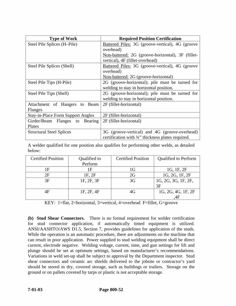
Type of Work Required Position Certification Steel Pile Splices (H–Pile) Battered Piles: 3G (groove-vertical), 4G (groove
overhead) Non-battered: 2G (groove-horizontal), 3F (fillet-vertical), 4F (fillet-overhead)
Steel Pile Splices (Shell) Battered Piles: 3G (groove-vertical), 4G (groove overhead) Non-battered: 2G (groove-horizontal)
Steel Pile Tips (H-Pile) 2G (groove-horizontal); pile must be turned for welding to stay in horizontal position.
Steel Pile Tips (Shell) 2G (groove-horizontal); pile must be turned for welding to stay in horizontal position.
Attachment of Hangers to Beam Flanges
2F (fillet-horizontal)
Stay-in-Place Form Support Angles 2F (fillet-horizontal) Girder/Beam Flanges to Bearing Plates
2F (fillet-horizontal)
Structural Steel Splices 3G (groove-vertical) and 4G (groove-overhead) certification with ¾” thickness plates required.
A welder qualified for one position also qualifies for performing other welds, as detailed below:
Certified Position Qualified to Perform
Certified Position Qualified to Perform
1F 1F 1G 1G, 1F, 2F 2F 1F, 2F 2G 1G, 2G, 1F, 2F 3F 1F, 2F, 3F 3G 1G, 2G, 3G, 1F, 2F,
3F 4F 1F, 2F, 4F 4G 1G, 2G, 4G, 1F, 2F
,4F KEY: 1=flat, 2=horizontal, 3=vertical, 4=overhead F=fillet, G=groove
(b) Stud Shear Connectors. There is no formal requirement for welder certification for stud connector application, if automatically timed equipment is utilized. ANSI/AASHTO/AWS D1.5, Section 7, provides guidelines for application of the studs. While the operation is an automatic procedure, there are adjustments on the machine that can result in poor application. Power supplied to stud welding equipment shall be direct current, electrode negative. Welding voltage, current, time, and gun settings for lift and plunge should be set at optimum settings, based on manufacturer’s recommendations. Variations in weld set-up shall be subject to approval by the Department inspector. Stud shear connectors and ceramic arc shields delivered to the jobsite or contractor’s yard should be stored in dry, covered storage, such as buildings or trailers. Storage on the ground or on pallets covered by tarps or plastic is not acceptable storage.
7-01-03 Page 800-52

2003 SPECIFICATIONS SECTION 807
Highlights of the welding code requirements concerning installation of stud shear connectors are as follows:
At the time of welding, the studs shall be free from rust, rust pits, scale, oil, moisture, and other deleterious matter that would adversely affect the welding operation.
The stud base shall not be painted, galvanized, nor cadmium-plated prior to welding.
The areas to which the studs are to be welded shall be free of paint, scale, rust, moisture, and other injurious material to the extent necessary to obtain satisfactory welds. These areas may be cleaned by wire brushing, scaling, prick-punching, or grinding.
The arc shields shall be kept dry. Any arc shields that show signs of surface moisture from dew or rain shall be oven dried at 250º F for two hours before use.
Particular attention should be paid to ensure that the studs are placed in accordance with the approved shop drawings, including stud height, diameter, and location on the beam. The tolerance for proper location of studs is plus or minus 1 inch. The minimum distance between studs is 1 inch and the minimum edge distance is 1 ½ inches.
The following procedure is to be used to qualify operators of the automatic equipment used to install stud shear connectors:
The operator welds two studs, either on similar material or on the field member
The Department inspector examines the stud and weld to verify a 360º weld and bends each stud 30º. If there are no separation or cracks in the weld, the stud is considered to be installed acceptably. The bent studs may be left in the bent position.
This procedure is to be performed at the beginning of each day, shift change, or change in stud diameter or length, or when there is sufficient reason to warrant retests. Any changes in the welding set-up shall require retesting.
In addition:
Installation of all stud shear connectors should also be checked to ensure 360º welds. Any studs not displaying a full 360º or that have been repaired by welding should be bent approximately 15º, opposite the lack of weld.
5% or a minimum of 5 studs on each individual beam/girder should also be tested by bending.
When the temperature is below 50º F, it is preferable that bending of studs be done by continuous slow application of load.
Arc shields shall be removed or otherwise broken free from studs.
In tension areas of the bridge member where unacceptable studs have been removed (or broken off during testing), the area shall be made smooth and flush prior to
Page 800-53 7-01-03
adding a replacement stud on the existing weld area. When loss of base metal occurs, the area is to be first repaired by the SMAW process using approved low-hydrogen electrodes and ground smooth.
In compression areas where stud failures are confined to shanks or fusion zones, a replacement stud shall be provided but the new stud may be welded adjacent to the unacceptable area in lieu of grinding smooth as above. When loss of base metal occurs, weld repair and grinding shall be as described above.
All repair welding is to be performed by welders qualified according to Department specifications. The shielded metal arc process using approved low-hydrogen electrodes shall be used. Areas where repair welding is performed shall be preheated according to Department specifications and other specifications referenced therein.
807.03 METHOD OF MEASUREMENT. Structural Steel is measured by the Pound (Kilogram) of Structural Steel in the fabricated structure. The quantities shown on the plans shall be considered as final unless exceptions (plus or minus) are noted.
"Painting Structural Steel" includes both the field prime and finish coats and is measured by the ton. This quantity is to be based on the final quantity of Structural Steel paid.
807.04 DOCUMENTATION - CURRENT ESTIMATES. Current Estimate documentation for Structural Steel and "Painting Structural Steel" shall be properly completed RWP's marked "Current Estimate". The "Basis of Estimate" may be based on a percent of plan quantity, a percent of plan quantity within certain Station limits or spans, or any other method that is understandable, accurate, and clearly stated on the RWP.
NOTE: If Structural Steel has been erected but not torqued, the Resident Engineer may withhold a percentage of the structural steel quantity erected until torquing has been accomplished.
7-01-03 Page 800-54

2003 SPECIFICATIONS SECTION 807
FIGURE 807-1
Page 800-55 7-01-03

FIGURE 807-2
7-01-03 Page 800-56
2003 SPECIFICATIONS SECTION 808
807.05 DOCUMENTATION - FINAL ESTIMATES. Final Estimate documentation for Structural Steel is based on plan quantity and noted variations. The Original Source Document (OSD) that must accompany the Final Estimate is the RWP marked "Final Document".
If there are no variations in plan quantity for Structural Steel, plan quantity shall be shown on the "Final Document" RWP with "Verified Plan Quantity" as the "Basis of Estimate".
When the final quantity differs from plan quantity, the "Final Document" RWP should state "Verified Plan Quantity with Noted Deletions/Additions". The variations in plan quantity should be documented by one or both of the following methods:
(1) By sketches and computations entered on or attached to the "Report of Work Performed", and/or
(2) By reporting the appropriate quantity and referring to the applicable approved Change Order number on the RWP. This change order must contain appropriate sketches and computations.
The Original Source Document (OSD) that must accompany the Final Estimate for "Painting Structural Steel" is the RWP marked "Final Document". This quantity is to be based on the final quantity of Structural Steel paid. The "Basis of Estimate" on the OSD should, therefore, refer to the appropriate OSD's for Structural Steel.
Examples of properly completed RWP's for both Current and Final Estimate Documentation for these items are found in Figures 807-1 and 807-2. Additional information on the completion of RWP's may be found in Subsection 109.02 of this Manual. RWP's marked "Current Estimate" should not be submitted with the Final Estimate.
SECTION 808 ELASTOMERIC BEARINGS
808.01 GENERAL. This item consists of furnishing and installing elastomeric bearings in accordance with the plans and Specifications.
The manufacturer of the bearings used must be listed in the Department's QPL and the bearings must be approved by Materials Division prior to use. Refer to this Section of the Specifications along with any applicable Special Provisions, and the Manual of Field Sampling and Testing Procedures for specific requirements.
Once the bearing pads arrive on the project and prior to installation, the inspector should examine the bearings for defects and check their dimensions against the plan dimensions.
NOTE: Care must be exercised in the positioning of these bearings on the caps. This should be thoroughly checked prior to installation of beams. Any bearing pad installation errors should be addressed prior to installation of beams.
Page 800-57 Rev. 12-14-04
808.02 METHOD OF MEASUREMENT. "Elastomeric Bearings" shall be measured by the Cubic Inch (Cubic Centimeter). The quantities shown on the plans shall be considered as final unless exceptions (plus or minus) are noted.
808.03 DOCUMENTATION - CURRENT ESTIMATES. Current Estimate documentation for "Elastomeric Bearings" shall be properly completed RWP's marked "Current Estimate". The "Basis of Estimate" may be based on a percent of plan quantity, a percent of plan quantity within certain Station limits or spans, or any other method that is understandable, accurate, and clearly stated on the RWP.
808.04 DOCUMENTATION - FINAL ESTIMATES. Final Estimate documentation for this item is based on plan quantity and noted variations. The Original Source Document (OSD) that must accompany the Final Estimate is the RWP marked "Final Document".
If there are no variations in plan quantity, it shall be shown on the "Final Document" RWP with "Verified Plan Quantity" as the "Basis of Estimate".
When the final quantity differs from plan quantity, the "Final Document" RWP should state "Verified Plan Quantity with Field Measured Deletions/Additions". The variations in plan quantity should be documented by one or both of the following methods:
By measurements, sketches, and computations entered on or attached to the "Report of Work Performed",
and/or
By reporting the appropriate quantity and referring to the applicable approved Change Order number on the RWP. This change order must contain appropriate sketches and computations.
Examples of properly completed RWP's for both Current and Final Estimate Documentation for this item are found in Figures 808-1 and 808-2. Additional information on the completion of RWP's may be found in Subsection 109.02 of this Manual. RWP's marked "Current Estimate" should not be submitted with the Final Estimate.
SECTION 809 PREFORMED JOINT SEAL
809.01 GENERAL. This item consists of furnishing and installing preformed elastic joint seals in accordance with the plans and Specifications. The Contractor is required to submit a drawing showing the proposed seal dimensions and tolerances.
This drawing must be approved by the AHTD Bridge Engineer prior to use. The joint seals must also be approved by Materials Division prior to use. The lubricant-adhesive used must either be approved by Materials Division or be listed on the Department's "Qualified Products List" prior to use. Refer to the Manual of Field Sampling and Testing Procedures. Joint seals must be installed in one piece, using tools recommended by the Manufacturer, and in a substantially fully compressed state. Joints
7-01-03 Page 800-58
2003 SPECIFICATIONS SECTION 810
are to be clean and dry when the preformed joint seals are installed. The top of the joint seal should, at all times, be approximately 1/4" (6 mm) below the roadway surface. Any temperature limitations on the use of the lubricant-adhesive recommended by the Manufacturer shall be observed.
809.02 METHOD OF MEASUREMENT. "Preformed Joint Seal" is measured by the Linear Foot (Meter) along the top of the joint seal. The quantities shown on the plans shall be considered as final unless exceptions (plus or minus) are noted.
809.03 DOCUMENTATION - CURRENT AND FINAL ESTIMATES. Refer to Subsections 808.03 and 808.04 of this Manual. Information contained in them is also applicable to this item.
SECTION 810 CLOSED CELL JOINT FILLER
810.01 GENERAL. This item consists of furnishing and installing closed cell joint filler in accordance with the plans and Specifications. It should be noted that:
All materials used must be approved by the Engineer of Materials Division prior to use.
The material must be furnished and installed in lengths covering one of the following:
* The full width of a bridge, or * A phase of construction, or * As shown on plans.
When field splices are required, a field splice of two 6" (150 mm) samples must be made by the Contractor and approved by Materials Division prior to allowing it.
Prior to installation of Closed Cell Joint Filler, joint surfaces should be cleaned in accordance with the Manufacturer's recommendation. Most Manufacturers recommend cleaning to a near white surface (SSPC-SP10). THIS IS AN IMPORTANT FACTOR IN OBTAINING A GOOD BOND BETWEEN THE STEEL AND THE CLOSED CELL JOINT FILLER MATERIAL AND SHOULD BE CAREFULLY MONITORED.
Care should be exercised to ensure that the correct size joint filler material is used. The uncompressed width of the joint material should be shown on the plans or selected from a chart in the plans. The Staff Construction Engineer should be contacted if there is a question about the correct size to use or if any of the joints fail.
If the joint is not constructed to the plan width, it may be necessary to adjust the width for the joint to function properly.
Page 800-59 7-01-03
810.02 METHOD OF MEASUREMENT. "Closed Cell Joint Filler" is measured by the Linear Foot (Meter) along the top of the joint seal. The quantities shown on the plans shall be considered as final unless exceptions (plus or minus) are noted.
810.03 DOCUMENTATION - CURRENT AND FINAL ESTIMATES. Refer to Subsections 808.03 and 808.04 of this Manual. Information contained in them is also applicable to this item.
SECTION 811 SHEET PILES
811.01 GENERAL. This item consists of furnishing and driving sheet piling (which are to remain in place) in accordance with the plans and Specifications. Sheet piling used for this item must be new and the Resident Engineer must have approved test reports on file prior to their use. The resulting structure shall be practically watertight at the joints and shall be given two (2) prime and one (1) finish coat of paint meeting the requirements of Section 807 of the Specifications. The painting shall extend from 18” (0.5 m) feet below the waterline or ground line to the top of the exposed pile.
811.02 METHOD OF MEASUREMENT. "Sheet Piles (____)" shall be measured by the Linear Foot (Meter) driven in place for the size specified. If it is necessary to cut off a sheet pile, payment will be made for 50% of that cut-off (up to the length specified by the plans) plus one 1 linear foot (0.3 m). If it is necessary to splice a sheet pile to a length longer than that shown on the plans, an additional 3’ (1 m) per splice shall be allowed.
No allowance will be made for cut-off or build-up in any portion of a pile which has been damaged, for splices made for the convenience of the Contractor, for extra length ordered for the Contractor's convenience, or for cutback necessary for splicing. Cut-off material shall be the property and responsibility of the Contractor.
811.03 DOCUMENTATION - CURRENT ESTIMATES. Current Estimate documentation for "Sheet Piles" shall be properly completed RWP's marked "Current Estimate". The "Basis of Estimate" may be based on a percent of plan quantity, a percent of plan quantity within certain Station limits, reference to the appropriate to the appropriate "Final Document", or any other method that is understandable, accurate, and clearly stated on the RWP.
811.04 DOCUMENTATION - FINAL ESTIMATES. Final Estimate documentation for "Sheet Piles" shall be properly completed RWP's marked "Final Estimate". The "Basis of Estimate" shall be "Actual Field Measurement".
Examples of properly completed RWP's for both Current and Final Estimate Documentation for this item are found in Figures 811-1 and 811-2. Additional information on the completion of RWP's may be found in Subsection 109.02 of this Manual. RWP's marked "Current Estimate" should not be submitted with the Final Estimate.
7-01-03 Page 800-60

2003 SPECIFICATIONS SECTION 811
Page 800-61 7-01-03
Figures 811-1 & 811-2
SECTION 812 BRIDGE NAME PLATE
812.01 GENERAL. This item includes furnishing and installing Bridge Name Plates in accordance with the plans and Specifications. The Resident Engineer should verify that the plate provided is listed on the QPL prior to its installation.. Refer to the Manual of Field Sampling and Testing Procedures. Also, the Resident Engineer should ensure that the Contractor installs Bridge Name Plates at the locations specified on the bridge plans.
812.02 METHOD OF MEASUREMENT. This item is measured by the unit ("Each").
812.03 DOCUMENTATION - CURRENT ESTIMATES. Documentation for Current Estimates for this item shall be on properly completed RWP's. The "Basis of Estimate" for this item will normally be reference to the appropriate "Final Document" RWP. Any other basis that is understandable, accurate, and clearly stated on the RWP may also be used.
812.04 DOCUMENTATION - FINAL ESTIMATES. Final Estimate documentation for this item shall be properly completed RWP's marked "Final Estimate". The "Basis of Estimate" shall be "Actual Field Count".
SECTION 813 DAMPPROOFING
813.01 GENERAL. This item consists of dampproofing (or waterproofing) composed of primer followed by one or more moppings of an asphalt coating in accordance with the plans and Specifications. Other systems may be used when approved by the Engineer. Dampproofing shall not be applied when the temperature is below 10º C (50°F). The first application shall be applied immediately after priming, and subsequent applications required shall be applied soon after the previous one has cooled.
813.02 METHOD OF MEASUREMENT. "Dampproofing" shall be measured by the Square Foot (Square Meter). The area measured shall be that actually covered, but shall not exceed that authorized.
813.03 DOCUMENTATION - CURRENT ESTIMATES. Current Estimate documentation for "Dampproofing" shall be properly completed RWP's marked "Current Estimate". The "Basis of Estimate" may be based on a percent of plan quantity, a percent of plan quantity within certain Station limits, reference to the appropriate to the appropriate "Final Document", or any other method that is understandable, accurate, and clearly stated on the RWP.
813.04 DOCUMENTATION - FINAL ESTIMATES. Final Estimate documentation for "Dampproofing" shall be properly completed RWP's marked "Final Estimate". The "Basis of Estimate" shall be "Actual Field Measurement". The
7-01-03 Page 800-62

2003 SPECIFICATIONS SECTION 816
measurements and calculations applicable shall be placed on or attached to the "Final Document" RWP's.
Examples of properly completed RWP's for both Current and Final Estimate Documentation for this item are found in Figures 813-1 and 813-2. Additional information on the completion of RWP's may be found in Subsection 109.02 of this Manual. RWP's marked "Current Estimate" should not be submitted with the Final Estimate.
SECTION 814 VACANT
SECTION 815 MEMBRANE WATERPROOFING
815.01 GENERAL. This item consists of application of a membrane waterproofing, consisting of the type designated in the plans and Specifications. Materials used should be approved prior to use.
The work is not to be performed when the temperature is below 50°F (10º C).
815.02 METHOD OF MEASUREMENT AND DOCUMENTATION - CURRENT AND FINAL ESTIMATES. Refer to Subsections 813.02 through 813.04 of this Manual. Information contained in them is also applicable to this item.
SECTION 816 FILTER BLANKET AND RIPRAP
816.01 GENERAL. This Section of the Specifications consists of furnishing and installing filter blanket and riprap in accordance with the plans and Specifications.
Materials must conform to the requirements listed for the applicable type of riprap. Testing shall be performed in accordance with the Manual of Field Sampling and Testing Procedures.
If fabric is used in lieu of granular filter blanket (Dumped Riprap), adjacent sections must overlap a minimum of 2’ (0.6 m) and the overlapped strip must be pinned with 6" (150 mm) [minimum length] U-shaped pins, single shaped pins with metal disc heads, or similar fasteners, at least every 4'. Fabric shall be overlapped in the direction of water flow.
Grout used in Dumped Riprap (Grouted) is a mixture of water, one part cement, and three parts sand.
Page 800-63 7-01-03

Figures 813-1 & 813-2
7-01-03 Page 800-64
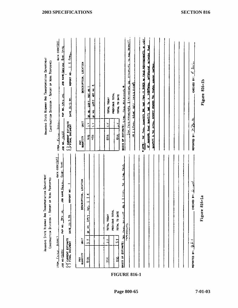
2003 SPECIFICATIONS SECTION 816
FIGURE 816-1
Page 800-65 7-01-03

FIGURE 816-2
7-01-03 Page 800-66
2003 SPECIFICATIONS SECTION 816
Class A concrete shall be used for Concrete Riprap. The Contractor performs QC/QA on this. Wire mesh reinforcement in Concrete Riprap shall be lapped a minimum of 150 mm (6”).
816.02 METHOD OF MEASUREMENT. Concrete, Dumped, Grouted, and Sacked Sand-Cement Riprap are measured by the Cubic Yard (Cubic Meter), in place. Filter Blanket is measured by the Square Yard (Square Meter). Quantities shown for these items on the plans are considered as final, unless substantial variations from the plans or errors in the plan quantities are noted. When exceptions to plan quantity are noted, the quantity must be field measured at these locations. Plan quantity at the other locations on the project, however, may still be used in conjunction with this
When measurement is required, Concrete, Sacked Sand-Cement, Dumped, and Grouted Riprap, along with Filter Blanket quantities will be computed using the area covered by them as field measured and the planned thickness of the riprap (plus any toewalls, etc., applicable). The AREA program should be used to compute the area. When used, the printout shall be attached to the appropriate RWP.
Foundation Protection Riprap is measured by the Ton (Metric Ton) in vehicles. NOTE: If the Specific Gravity of Foundation Protection Riprap is greater than 2.80, the pay measurement is reduced by multiplying the amount used by the ratio of 2.8 and the actual Specific gravity.
816.03 DOCUMENTATION - CURRENT ESTIMATES. Current Estimate documentation for these items shall be properly completed RWP's marked "Current Estimate". The "Basis of Estimate" may be based on a percent of plan quantity, a percent of plan quantity within certain Station limits, reference to the appropriate to the appropriate "Final Document", or any other method that is understandable, accurate, and clearly stated on the RWP.
816.04 DOCUMENTATION - FINAL ESTIMATES. Final Estimate documentation for Concrete, Dumped, Grouted, and Sacked Sand-Cement Riprap shall be properly completed RWP's marked "Final Estimate". The "Basis of Estimate" shall be "Verified Plan Quantity" or "Verified Plan Quantity with Field Measured Additions/Deletions." Applicable measurements and calculations applicable shall be placed on or attached to the "Final Document" RWP's.
The computerized Daily Reporting System should be used to document Foundation Protection Riprap. This will be done in the same manner as for Selected Material (Class SM__) measured by the Ton (Metric Ton) (Subsection 302.03 of this Manual).
Examples of properly completed RWP's for both Current and Final Estimate Documentation for this item are found in Figures 816-1 and 816-2. Additional information on the completion of RWP's may be found in Subsection 109.02 of this Manual. RWP's marked "Current Estimate" should not be submitted with the Final Estimate.
Page 800-67 7-01-03

SECTION 817 TIMBER BRIDGES
817.01 GENERAL. This Specification covers construction of bridges using treated and/or untreated timber in accordance with the plans and Specifications. This Specification lists other material Specifications to which timber and hardware used must comply and should be used as a reference to ensure that all materials incorporated into the work meet its requirements. In addition, testing of materials used should comply with the Manual of Field Sampling and Testing Procedures.
Unless otherwise specified, structural lumber must be pressure treated with preservative and shall be either Southern Yellow Pine or Douglas Fir.
817.02 METHOD OF MEASUREMENT. Timber for bridges shall be measured by the Thousand Board Feet (1" X 1' X 1000' = 1000 Board Feet) [Cubic Meter] in place. The measurements shall be based on the nominal widths and thicknesses. Quantities for timber, except flooring, will be computed using plan dimensions or dimensions authorized by the Engineer. .
NOTE: No measurement is made of materials cut off or wasted, nor for timber used for erection purposes.
817.03 DOCUMENTATION - CURRENT ESTIMATES. Current Estimate documentation for these items shall be properly completed RWP's marked "Current Estimate". The "Basis of Estimate" may be based on a percent of plan quantity, a percent of plan quantity within certain Station limits, reference to the appropriate to the appropriate "Final Document", or any other method that is understandable, accurate, and clearly stated on the RWP.
817.04 DOCUMENTATION - FINAL ESTIMATES. Final Estimate documentation for these items shall be properly completed RWP's marked "Final Estimate". The "Basis of Estimate" shall be "Actual Field Measurement". Measurements and computations applicable shall be contained on or attached to the "Final Document" RWP.
SECTION 818 UNTREATED AND TREATED TIMBER PILING
818.01 GENERAL. This Specification deals with furnishing and driving treated and untreated timber piling in accordance with the plans and Specifications. Timber piles which will be below water level at all times may be of any species that will withstand driving. Treated pile must be Southern Yellow Pine or Douglas Fir. This Specification, in addition to the specific requirements, also requires compliance with certain portions of Section 817 (Timber Bridges) and 805 (Piling). When this item is required, all should be used as references to ensure compliance with the Specification.
7-01-03 Page 800-68

2003 SPECIFICATIONS SECTION 820
NOTE: Pile heads of Treated timber piling must be treated to prevent decay, using Zinc, fabric, or other approved covering.
818.02 METHOD OF MEASUREMENT. Timber piling is measured by the Linear Foot (Meter) accepted and remaining in the finished work after all cut-offs and/or build-ups have been made, based upon lengths shown on plans or established by the Engineer.
Cut-off shall be measured at 50% of the cut off length, up to the approved length. No allowance will be made for any length furnished in excess of the lengths shown on the plans or established by the Engineer.
An additional 4’ (1.2 m) shall be included in the measurement for splices required due to the established lengths being too short.
No allowance will be made for cut-off or build-up of any portion of a pile which has been damaged; for splices made for the convenience of the Contractor; for extra length ordered for the Contractor's convenience; or for cut-off of 1’ (0.3 m) or less necessary to establish uniform bearing of the cap on the piles.
Cut-off material shall become the property and responsibility of the Contractor.
818.03 DOCUMENTATION - CURRENT AND FINAL ESTIMATES. Completion of Form 19-167 "Piling Record" is required for Current and Final Estimate documentation for Piling. No further documentation is required. Refer to Appendix III for instructions in completion of this form.
SECTION 819 VACANT
SECTION 820 CLEANING AND PAINTING EXISTING STRUCTURAL STEEL
820.01 GENERAL. This item includes the cleaning and painting of steel structures in accordance with the plans and Specifications. This work includes protection of traffic and pedestrians and protection of streams, lakes and reservoirs. Paint and painting procedures must comply with the same requirements as painting new Structural Steel. (Refer to Subsections 807.58 through 807.67 of the Specifications.) The cleaning requirements for the Structural Steel, however, vary on this item, depending upon its condition. Section 820 of the Specifications should be utilized as a reference when this item is used in a contract.
NOTE: Upon request, the Heavy Bridge Maintenance Engineer will provide instructions for the testing procedures involved.
Page 800-69 7-01-03
If the material removed is considered hazardous material, special testing, handling, and disposal will be required. The Standard Specifications and Special Provisions detailing such special handling must be carefully followed.
820.02 METHOD OF MEASUREMENT. This item is measured by the Ton (Metric Ton) of Structural Steel. Quantities on the plans shall be final.
NOTE: If both Type I and Type II Cleaning and Painting are included in the contract, the quantities of each may vary depending on field conditions determined by the Resident Engineer. (The total tons of structural steel for a structure will not change. I.e., if additional Type II cleaning is required, the quantity for Type II will increase and the quantity for Type I will decrease by a like amount.)
820.03 DOCUMENTATION - CURRENT ESTIMATES. Current Estimate documentation for these items shall be properly completed RWP's marked "Current Estimate". The "Basis of Estimate" may be based on a percent of plan quantity, a percent of plan quantity within certain Station limits or on a certain structure, reference to the appropriate to the appropriate "Final Document", or any other method that is understandable, accurate, and clearly stated on the RWP.
820.04 DOCUMENTATION - FINAL ESTIMATES. Final Estimate documentation for these items shall be properly completed RWP's marked "Final Estimate". The "Basis of Estimate" shall be "Verified Plan Quantity" if plan quantities are considered correct.
SECTION 821 MODIFICATION OF EXISTING BRIDGE STRUCTURES
821.01 GENERAL. This item consists of modifying existing bridge(s) according to the plans and Specifications in order to accommodate remodeling the structures.
When widening a bridge deck, it shall be sawed 1" (25 mm) deep along the line of removal, and 25 mm (1") round holes shall be drilled at 8" (200 mm) centers to within 2” (50 mm ) of the bottom of the slab along this line in the area of removal. Also, a plane of weakness shall be sawed or chiseled along this line on the underside of the slab. Reinforcing steel shall not be cut, but shall be cleaned and shall extend into the new concrete.
821.02 METHOD OF MEASUREMENT. This item is measured by the lump sum for each bridge.
821.03 DOCUMENTATION - CURRENT ESTIMATES. Current Estimate documentation for this item shall be properly completed RWP's marked "Current Estimate". The "Basis of Estimate" may be based on a percent of plan quantity, a percent of plan quantity for a certain structure, or any other method that is understandable, accurate, and clearly stated on the RWP.
7-01-03 Page 800-70

2003 SPECIFICATIONS SECTION 822
821.04 DOCUMENTATION - FINAL ESTIMATES. Final Estimate documentation for these items shall be properly completed RWP's marked "Final Estimate". The "Basis of Estimate" shall be "Observation of Completed Work".
SECTION 822 REPAIR AND OVERLAY OF CONCRETE BRIDGE DECKS
822.01 GENERAL. This item consists of repairing and/or overlaying (with concrete) of concrete bridge decks in accordance with the plans and Specifications.
(a) Bridge Deck Repair. Unsound portions of the concrete bridge deck are removed. If the bridge deck is to be overlaid, the concrete used in the repair must meet this Specification (822.02) and is to be placed with the overlay. If the bridge deck is NOT to be overlaid, the concrete used in the repair may be either Class S(AE) or meet this Specification's requirements.
(b) Bridge Deck Overlay. The existing bridge deck is to be removed to a depth of 12 mm (1/2") below the existing finished surface and overlaid with concrete complying with this Specification (822.02). The final elevation of the bridge is established by the plans. The minimum thickness of concrete above reinforcing steel or the prepared surface, however, is 45 mm (1 3/4").
NOTE: The Department performs Acceptance Testing on this concrete.
(c) Equipment. Equipment used must comply with Subsection 802.03 of the Specifications. Some of the requirements include:
A mechanical screed must be used on bridge deck overlays.
It must have sufficient vibrators on it to consolidate the concrete in accordance with the Specifications (98% maximum).
Jackhammers heavier than nominal 30 pound class are not permitted and shall not be used at an angle in excess of 45 degrees from the deck.
Chipping hammers heavier than nominal 15 pound class are not permitted and shall not be used at an angle in excess of 45 degrees from the deck.
Sawing equipment must be capable of sawing the full depth of concrete removal.
(d) Construction Methods. The concrete shall be removed to the depth specified by the Engineer (in accordance with the plans and Specifications). On bridge deck repair without overlay or where reinforcing steel has lost its bond to concrete, concrete shall be removed a minimum of 3/4" (19 mm) below reinforcing steel. On bridge deck overlays, the Contractor shall check to ensure that sufficient concrete has been removed to obtain the minimum 1 3/4" (45 mm) overlay by running the screed over the area prior to the pour.
Page 800-71 7-01-03
Immediately before applying grout, the surfaces shall be sandblasted, followed by air or water cleaning. A thin coating of grout for bonding is then applied to the DRY prepared surface. Placement of concrete shall be a continuous operation throughout the pour. The surface shall be tined in accordance with Section 802.20 of the Specifications. Joints must be 1/4" x 1" (6 mm x 25 mm) and are to be prepared in the same manner as concrete paving joints and filled with approved silicone (Subsections 501.03 and 501.04 of the Specifications). Curing shall be accomplished in the same manner as for bridge decks, except that the deck shall be kept continuously wet until it has cured for 72 hours at temperatures above 55°F (13ºC).
Concrete shall not be placed if the temperature is below 40°F (4º C) and the temperature of the concrete shall not exceed 85°F (28ºC).
NOTE: QC/QA is to be performed in accordance with Subsection 802.06 of the Specifications. The Resident Engineer should straightedge the finished deck.
822.02 METHOD OF MEASUREMENT. These items are measured by the square yard (square meter). If an area of bridge deck repair is accomplished and then overlaid, the area is to be measured for both pay items.
822.03 DOCUMENTATION - CURRENT ESTIMATES. Current Estimate documentation for these items shall be properly completed RWP's marked "Current Estimate". The "Basis of Estimate" may be based on a percent of plan quantity, a percent of plan quantity within certain Station limits or structure, reference to the appropriate to the appropriate "Final Document", or any other method that is understandable, accurate, and clearly stated on the RWP.
822.04 DOCUMENTATION - FINAL ESTIMATES. Final Estimate documentation for these items shall be properly completed RWP's marked "Final Estimate". The "Basis of Estimate" shall be "Actual Field Measurement". Measurements and computations applicable shall be shown on the "Final Document" RWP or on attached sheets.
7-01-03 Page 800-72