7.4 CIVIL AND ARCHITECTURE -...
107
473 7.4 CIVIL AND ARCHITECTURE
Transcript of 7.4 CIVIL AND ARCHITECTURE -...

473
7.4 CIVIL AND ARCHITECTURE
474
CIVIL AND ARCHITECTURE GENERAL PROVISION FOR AIS SUB-STATION WITH OFFICE BUILDING
7.41 References 7.4.1.1 General The design and construction shall conform to the latest edition of the relevant codes and standards. Any proposed substitution for the listed standards by an equivalent standard will be subject to approval by the Engineer. Relevant standards include. 7.4.1.2 Design and Construction Standards BS 12 Portland Cement BS EN 124 Gully and Manhole tops for vehicular and pedestrian areas BS 812 Testing Aggregates BS 882 Aggregates from natural sources for concrete BS 1377 Methods of test for soil for civil Engineering purposes BS 1722:Part10 Anti-intruder fences BS 1881 Testing concrete BS 2853 Design and testing of overhead runway beams BS 3148 Methods of test for water for making concrete BS 3921 Clay bricks BS 4449 Steel bars for the reinforcement of concrete BS 5262 External renderings BS 5395 Stairs, ladders and walkways BS 5572 Sanitary pipe works BS 5628 Code of practice for use of masonry BS 5930 Code of practice for site investigations BS 6031 Code of practice for earth works BS 6367 Code of practice for drainage of roofs and paved areas BS 6399: Part1 Code of practice for dead and imposed loads BS 6399: Part 2 Code of practice for wind loads BS 6465 Sanitary installations BS 6651 Code of practice for protection of structures against lightning BS 6700 Design, installation, testing and maintenance of services
supplying water for domestic use. BS 8004 Code of practice for foundations BS 8005 Sewerage BS 8100 Lattice towers and masts BS 8102 Code practice of protection of structures against water the ground
structural use of concrete. BS 8110 Structural use of concrete BS 820 Lightning of buildings BS 8215 Code practice for design and installation of damp-proof courses in
masonry BS 8290 Suspended ceilings Bs 8301 Code of practice for Building drainage
475
7.4.2 Design Both Architectural and Structural Design shall be submitted by the contractor to the employer for approval. 7.4.2.1 Architectural and structural Requirements of Buildings The details Architectural, Structural & other related drawing and design with Green Building concept shall be submitted by the contractor to employer for approval.
1. Structure Green Building Technology.
: Modern Architectural designed R.C.C or Steel Framed Structure featured by
2. Partition Wall • For all Exterior wall thickness should be 10 (ten) inches and interior wall
thickness should be 5 (five) inches and to be used 1st Class Bricks.
:
• All Brick wall should be plastered both sides as per standard (Except where Fare-Facing Treatment to be used)
• In case of R.C.C. works 20mm down graded Stone chips should be used.
3. Covered AreaSpecific Functions - Control Room, Battery room, Cable Trench, Store, Office Rooms, Residential Accommodation, walkway, open Space & stair case etc.
: Minimum required area in Building are included with service areas & Other
4. Foundation (For AIS Regular type Sub-station)
: Considering 02 storied building (no Basement) (G+1)
• Plinth Level at +3ft above from Ground Level • Ground Floor clear height 9’-6” ft Cable Trench & Ancillary Facility • 1st Floor clear height 13’-6” ft for Control room
5. Floor/Roof Finish
• To be used 36 inch x 36inch size European standard Mirror Polished :
Homogeneous tiles for Ground & 1st Floor. • Standard Quality Tiles for walk way or other common space.
6. Toilet/ Sanitary
• Floor and full height wall of the Toilet should be furnished by European :
Standard Tiles with decorative boarder. • To be used European Standard Commode, Basin and others Sanitary
Fittings & Fixtures (such as Pillar Cock, Bib Cock, Push Shower etc.) should be European Standard as well as approved sample and design.
• To be Constructed 50 users septic tank, inspection pit, sewerage line, apron, drain etc.
• To be provided water supply system with Deep Tube well & over head water tank.
7. Electrical Fittings & Fixture
• Concealed Electrical wiring by Eastern/BRB/Paradise :
Fire Resistant Cable • European Made MK type Gang switch, socket MCB etc • Provision for Internet facilities system, Dish Line, Telephone
& Intercom wiring.
476
• Sufficient Earthling facilities. • To be used LED Light • To be provided sufficient Air Conditioner • To be provided sufficient Ceiling Fan
8. Interior Wall Finishing used over the Plastering work of interior wall and ceiling.
: Smooth Finished & soft colored Plastic paint should be
9. Exterior Wall should be used over the Plastering work of Exterior wall. Some where should be used Ceramic Facing brick / Rustic Tiles
: Smooth Finished & Architectural approved colored weather coat
10. Window minimum 5mm thickness glass.
: Window should be made Standard Quality Thai Aluminum frame and
11. Door Teak, Teak Chambal, Chapalish etc. which shall be approved by the owner's engineer.
: Door Frame and Shutter should be made by solid wood such as Burma
12. Stair Railing
: Should be used approved designed SS Railing in the Stair case.
13. Sign, Signal & Annotation :
● Integrated Design of Different kind of Indicators like- Acrylic Sign Board, LED Sign Board, Neon Sign Board,
Reception Sign Board, Safety Sign, PVC Letters, Glow Sign Board, Customized Display Boards, Overhead Signage, Metal Nameplates, Commercial Sign Boards, Outdoor Signs, Electronic Sign Boards etc. should be provided in the design & construction.
● Digital LED Signboard with the features of- Excellent visibility (even in daylight); Good quality at reasonable price and light weight; Simple installation, Safe to touch and clean; Changing color for attracting attention; Extremely low power consumption. ● Should be provided the Accessories like Adaptor and chains etc.
14. Approval & Test Materials & Item (if required) should be tested from any authorized Institutions of Bangladesh furnished by the Contractor.
The columns of the ground story shall be extended above roof level to permit starter bars to be left in place for a future story. An external concrete open staircase shall be provided up to the roof. The roof shall be a RCC slab designed for 5 kN/m2 live load for all floor as per BNBC . If a future story is not required, a fixed ladder of galvanized steel shall be provided up to the roof or provide temporary CI sheet shade over the stair case as per direction of the employer.
: Over all Approval should be taken from concern office of the BPDB.
477
The main entrance to all buildings shall be shaded, either by a projection of the roof over the entrance verandah or by a separate roof at a lower level. This area of roof shall also be lime terraced and drained by rainwater pipes. The head of each down pipe shall be fitted with an enlarged hopper and purpose made cast iron grill set into recess in the roof projection. Window openings shall be fitted with protruding concrete sunshades above and at the sides of the openings.
All external walls shall be 250 mm first class brick work also provide 237.4mm x 68.75mm x 12.5mm (9.5”x2.75”x0.5” ) or any other standard sizes of Mirpur ceramics facing bricks or similar approved, or rendered Rustic Tiles as required by the architectural plan. The internal walls shall be generally of 125 mm thick first class brick work. Internal walls shall all be rendered and receive one sealer coat plus two finishing coats of Plastic emulsion paint. All brickwork shall be tied into the RCC frame by galvanized ties.
Externally, rendered walls shall receive primer plus two finishing coats of PEP acrylic external quality paint or similar approved.
The height of control rooms shall be provided about 1 (One) meter clearance over the top of the cabinets to the underside of the false ceiling. In the switch gear rooms, about 1 meter clearance shall be provided over the switch gear to the underside roof slab but the Contractor shall provide a greater clearance if it is required to remove equipment. The clearance may be reduced below down stand beams provided no equipment is required to be removed from the top of the switch gear. All rooms in any building shall be one height.
Control buildings housing switch gear and control equipment shall include a cable basement to facilitates connection to the equipment. Basements shall be constructed so as to protect the building sub structure from water in accordance with BS 8102.
7.4.2.2 Ground conditions, Foundations and Site Investigation (a) Fill Sites On fill sites where the depth of fill exceeds 3 meters the contract assumes piled foundations shall be installed below buildings. If placed foundations are found to be unnecessary in the final site investigation report, a reduction in contract value shall be agreed on the basis of schedule rates. Piles shall be concrete (cast in situ or pre-cast) complying with BS 8004. Where timber piles are used, adequate strip footings shall be provided to support the building after the timber piles have deteriorated by which time settlement will be complete.
On every fill site the Contractor shall prove that his switchyard foundation will not suffer settlement greater than 20 mm by constructing a foundation and load testing this to twice the design bearing pressure for a minimum of 20 days.
Outdoor equipment shall be provided with spread footings. The Contractor will be provided by the Employer with a survey of soil levels prior to filling. The Contractor shall impose the site layout on the survey to check for uneven depth of fill below any foundation and where uneven depth of fill exists his foundation proposals shall restrict final differential settlement to a 1 in 400 slopes. If a fill site has not been exposed to one wet season before foundation work starts, the Contractor shall flood the site to a depth of 50 mm for 10 days (Not required on hydraulic fill site). This requirement is because silty sands will generally compact to a denser condition on first time flooding.
478
On all fill sites the Contractor shall pipe rainwater from pipes down to paddy level and shall prevent water pond in open foundations and backfill all foundations as soon as possible. The Contractor shall monitor settlement of the fill (by placing concrete posts 50x50x750 mm deep on a 10 meter grid and taking readings) at 30 day intervals from the time he is given access to each fill site. When a fill site is handed over to the Contractor, The Contractor shall become responsible for maintaining the entirely of the fill in good condition, including all batter slopes. (b) Unfilled Sites Original delta levels are generally 4 meters below road level. Therefore most sites are historically fill sites but fill settlement can sensibly be considered complete, where fill is over 3 years old. (c) Site Investigation The Contractor may appoint a sub contractor to carry out the site investigations but all work and all lab work shall be witnessed by one of his own staff who shall countersign all recorded data. The site investigations and analysis of the data in a final report giving full details of foundation proposals shall be completed at each site by the programmed date. Boreholes shall be taken on a 25 meter grid with at least three additional boreholes beside each building. Additional boreholes may also be required where uneven fill depth is encountered. The boreholes shall be located to an accuracy of ±0.5 m and shall be located to site layout. Boreholes shall be a minimum of 20 meters depth or twice building footing width, whichever is greater or as per site condition & decision of the employer. All boreholes shall be back filled with compacted sand. In each bore hole the following tests shall be carried out : Standard penetration tests at 1.5 meter intervals. Undisturbed samples shall be taken at around 1.5 meters depth and 3 meters depth and tested by unconfined compression tests. One dimensional consolidation tests shall be carried out on undisturbed samples taken at 1,5,3 and 4.5 meters depth. The samples shall be saturated and the range of applied pressure shall fully reflected the in situ conditions. Graphs showing void ratio(e) and applied pressure shall be submitted along with the coefficient of compressibility for the range of loading anticipated. Mv shall be in m2/MN and shall be recorded at each stress increment. The coefficient of consolidation, cv, shall be given in m2/year. Particle size analysis shall be carried out for each stratum and specified gravity, moisture content, liquid limit and plastic limit determined. Ground water level shall be determined by dipping the boreholes. Where collapse of the boreholes occurs, casing shall be used and left in until the water level remains constant for two days. In cohesive soils a vane test to BS 1377 : part 9 shall be carried out at three different depths. The Contractor shall check the aggressively of soil and ground water at each site to concrete and take all measures necessary to ensure the long term durability of concrete. (d) Site Investigation Report
479
The report shall be submitted by the key date at each site given in the program. The Contractor shall submit 2 copies of the report to the Engineer. The report shall propose full details of foundations and loading thereon and shall provide estimates of likely settlements and differential settlements. The report shall be the work of the Contractor’s own foundation Engineers. If the Contractor uses a local site investigation contractor, he shall appoint one of his own staff to oversee the entire operation and each piece of data shall be countersigned by this person. The Contractor shall supply, install and test at least one of the types of Pile in accordance with the approved design and the drawing showing the Piling arrangement. Each Pile shall be suite existing the sub-strata at the site. (e) Foundations
The minimum depth of all foundations shall be : (i) Transformer bases bound 0.9 m (ii) All other switchyard foundations 1.1 m (iii) Control building foundations, 1.5 m including all wall foundations and internal wall foundations
(iv) Boundary wall foundations 1.1 m All formations shall be hand rammed or mechanically compacted before placing 70 mm minimum thickness of Class B concrete blinding, within 24 hours of bottoming excavation, which blinding shall project 300 mm minimum distance beyond all footings. Each footing shall be inspected by the Engineer. Where soil condition is poor (on fill sites or already filled sites) or where the Contractor leaves foundations exposed and soil conditions deteriorate, one of the following measures shall be carried out as agreed with the engineer. (i) Blinding depth and projection shall be increased (ii) Soft soil shall be removed and replaced with compacted viti sand with the top 200
mm consisting of viti sand and brick chips. The cost of this work shall be borne by the Contractor. Between column footings all walls, including all internal wall shall be provided with a reinforced concrete strip footing of minimum dimension 800 mm wide by 250 mm deep placed at the same level as column footings and linked structurally to the footings. In addition column footings shall be tied at foundation level and also floor level by beams to every adjacent column in both orthogonal directions. These beam shall be designed to resist 1 in 200 differential settlement without distress and shall be capable of resisting the earthquake load of Chittagong region as per BNBC 2012 The deepest parts of any foundations shall be completed first. All foundations shall be completed and back filled, including all cable tunnel and cable trench work inside buildings, before walls are raised above floor levels. All other foundations shall be back filled within 7 days of completing concerning. All exposed concrete and outer surfaces of cable trenches and cable tunnels shall receive two coats of bitumastic paint before back filling to reduce ingress of water. The Concrete surface shall be ground smooth and all air holes etc. filled (rubbed down with a cement slurry) before painting. The Contractor shall monitor settlement of all foundations each month and report this settlement to the Engineer until settlement has reduced to less than 1.5 mm in 3 months.
480
The tops of all foundations shall terminate 1000mm above site average finished surface level. All exposed edges shall have 20 mm x 20 mm chamfers. Excavation shall only be carried out when the ground water table at least 1000mm below foundation level. The excavation shall be kept dry during the construction period by providing sumps and pumps as required. During the rain season, shelters shall be erected over all open excavations. Any over excavation shall be filled with Class B concrete. All back fill shall be completed to 95% maximum dry density as defined by BS 1377 test method. 2.5 Kg rammer. Before starting foundation work the Contractor shall clear all sites of trees, tree roots shrubs, debris, surplus soil, and any buildings. Foundations shall be designed to resist uplift, assuming the water table is at ground level and the weight of soil resting on a foundation is that included within a 150 frustum. On fill sites where the depth of fill exceeds 3 meters, the Contractor shall provide piled foundations in accordance with BS 8004 for control buildings. If timber piles are used, adequate strip footings shall be provided to support the structure after the timber pile has deteriorated, by which time the fill will be fully consolidated. One working pile chosen by the Engineer shall be load tested at each site to 150% of design load in accordance with BS 8004. 7.4.2.3 Drainage The entire surface within boundary walls shall be of uniform sloping site, sloping at q in 150 minimum slope to open channels around the entire perimeter. These channels shall be designed for a rainfall intensity of 60 mm per hour. Out side the boundary wall the contractor shall be responsible for drainage up to 20 meters from the wall and will at some sites need to construct outlets with suitable erosion protection down to paddy level. The concrete wall of cable trenches shall project at least 70 mm above brick paving level to prevent run off entering the cable trench. The floors of all cable trenches /tunnels shall be sloped to soak ways. The cable trenches shall be free from surface water drainage. If the cutoff area exceeds 30 m2 it shall be drained by a 200 mm minimum diameter concrete pipe to the boundary drain. The Contractor’s drainage design shall avoid all pond water to avoid forming a mosquito breeding ground . All drainage pipe work within buildings shall be ductile iron, generally of 100 mm diameter. Floor drains shall be placed in each battery room and toilet. External Pipe work shall be 150 mm minimum diameter concrete pipes at a minimum depth of invert of 700 mm. Where pipes, including existing pipes along with site, are less than 400 mm above adjacent foundations they shall be surrounded in concrete. Where required, drainage pipes shall be kept below cables, allowing 1.1 m cover to top of pipes.

481
Manholes shall be of brick construction with 600mm x 600mm clear openings and air tight ductile iron covers to BS EN 124. Manholes shall be located at each change of direction. Minimum fall on all pipelines shall be 1 in 80. Manhole shall not be located in roads. The Contractor shall be responsible for all negotiations with local authority WASA where a connection to a public sewer is proposed. Where high water levels in public sewers may cause effluent to back up into a site, non return valves shall be fitted. The Contractor shall provide all protection required to existing sewers and shall deepen foundations, including boundary wall foundations, where required all foundations are below adjacent sewers. The Contractor shall draw longitudinal sections of all pipelines. Each control building shall be provided with a septic tank designed for 10 users and a soak away of open brick construction 11 m deep by 2.2 m diameter filled with broken bricks. The septic tank shall be located at least 15 meters from buildings. Other buildings shall have septic tanks designed for the required number of users. All foul drains shall vented by a vent pipi to above roof level. The inner surface of all manholes and septic tanks shall be painted with 2 coats of bitumastic paint to protect it against sulphate attack. The septic tank shall have access holes directly over the inlet pipes and outlet pipes. Where public sewers exist alongside a site, the Contractor shall connect directly to the foul sewer, provided effluent from the sewer is treated. The Contractor shall construct the drainage first to ensure that at no stage is rainwater ponded on any part of the site. All rainwater shall be able to run off the site or shall be immediately pumped off site by the Contractor. The Contractor shall complete all necessary drains before casting any roof and large concrete area which will create large run off. The condensate drains for the air conditioning shall also be connected to the drainage. Two vents of minimum height 2.2 m shall be provided on each septic tank.
If a town’s water supply is unreliable, the roof rain water shall be collected in an underground tank of standard Employer’s design. Scope of this work shall be agreed at Bid stage. 7.4.3 Earth Work 7.4.3.1 Scope This clause covers the performance of all works in connection with the required excavation for the various type of foundations and equipment, as shown in the drawing, or any other excavation and banking that may be necessary during the progress of works including the removal, use or disposal of all excavated materials.
7.4.3.2 Clearing
(1) Clearing shall mean include the remove of trees and shrubs, stumps and other objectionable matters from the area necessary for the works. The contractor shall cut and remove them from the project area or turn them as approved by the Engineer.
(2) By no means shall the contractor fell any trees outside the premise of the construction site without permission of the parties concerned even if such trees cause obstacle against smooth execution of the work. Therefore, any such trees shall be felled upon negotiation with and permission of the possessor.
7.4.3.3 Excavation
(1) Excavation under this section shall consist of the removal, hauling, dumping and satisfactory disposal of all materials from required excavations.

482
(2) The excavated slope surface shall be protected against any erosion due to heavy rains during construction period. Should any damage be caused on any face of slope, the contractor shall immediately repair any such damage at his expense.
(3) Excavation shall be carried out by adopting a suitable excavation for the ground so as not to loosen the ground outside the excavation. If necessary, temporary sheeting shall be constructed.
(4) During excavation, work shall be performed carefully so as not to cause any damage to adjacent structures and buried structures.
(5) If the excavated material is to be temporarily stockpiled, designated spaces shall be kept from the shoulder of the road while considering the earth pressure at the excavated surface and the working space. Temporary sheeting or other such structures, if necessary, shall be constructed so that the stockpile can be protected from damage or being washed away.
(6) Excavation of road, if any, shall be done in such a manner as not to hamper vehicular traffic. If excavation is to be performed in the vicinity of residences, appropriate care shall be taken so as not to hinder the passage of residents.
Spoils, materials and equipment shall be carefully handled. (7) After completion of excavation, excavated widths and bottoms shall be subject to inspection
by the engineer. (8) Blasting shall not be employed during excavation. (9) Any and all excess excavation for the convenience of the contractor or over-excavation
performed by the contractor for any purpose or reason, except may be ordered in writing by the engineer, and whether or not due to the fault of the contractor, shall be at the expense of the contractor. All such excess excavation and other excavation shall be filed at the expense by the contractor with materials approved by the engineer.
(10) The contractor shall be entitled to request the engineer in writing to change the excavation
line as required according to the soil conditions of the foundation following the progress of excavation. In such a case, upon excavation up to the laid excavation line, the contractor shall prepare the detailed design drawing of the said foundation and submit it to the engineer for his approval.
(11) All objectionable materials such as, oil, mud, rock fragments, loose rock, chips, mortar,
organic matters and stagnant water, shall be removed from the surface of the foundation.
7.4.3.4 Sheeting (1) Sheeting shall be of the type that is suitable to the condition of foundation and Ground
water and shall have a safe structure.
(2) If sheet piles on retaining piles are to be driven at the piling location in the vicinity of buried structures, where they shall be investigated and confirmed by manual trench excavation etc. prior to piling in order to protect these structures from being damaged when piles are to be pulled out, carefulness shall be taken into account to cause no damage to the buried structures.
7.4.3.5 Banking
Foundation of banking shall be treated as follows: (1) Any material having a harmful effect on banking shall be removed.
(a) Where inflow of ground water is expected, it shall be treated so as not to cause inundation.
483
(b) In case of sloped ground with unfavorable conditions, such as unsuitable soil, poor drainage, etc, a method, such as excavating the ground into steps in advance in order to increase its stability, shall be planned and reported to the Engineer.
(2) Unless otherwise specified, settlement allowance shall be 3 per cent of the height of the
banking and the surface shall be graded evenly within =5 cm. (3) Materials for banking shall not include any harmful materials, such as fertile soil or pieces
so wood. (4) Materials for banking shall not be of an extremely swelling nature. (5) Impermeable clay shall not be used for back-filling of a structure which is susceptible to
earth pressure. (6) Banking shall be formed by spreading soil of less than 50 cm in thickness and by sufficiently
compacting each layer. (7) The type of compactor shall be one that is suitable or banding materials. (8) Materials for banking shall be so treated as to have optimum water content in percent of
dry weight. (9) Rocks shall be spread out evenly so as not to form any void space. (10) Temporary facilities shall not be buried in banking. If it becomes inevitable to do so, it shall
be reported to the engineer and shall be approved by the engineer, upon which appropriate measures shall be taken to prevent any unfavorable effect on the banking.
(11) As a standard, extent of satisfactory compaction shall be as follows : K75 =1.5 Kg./cm3 or more Where : K 75 is a coefficient of bearing capacity determined by the plate load test. When required by the engineer, the contractor shall perform in-sity tests and
penetration test to confirm the extent of compaction and the result shall be submitted to the engineer.
(12) Any banking work on rainy day shall be carried to upon approval of the Engineer. 7.4.3.6 Back-Filling (1) Back filling shall be executed as construction proceeds along with the removal of shoring
and other materials at the back filling site. When sheeting is to be left and buried in order to prevent shear failure of soil or due
to some other inevitable reasons, it shall be done so according to the direction of the engineer.
(2) Except those which are specified in the specifications or the drawings, all the materials for
back filling shall be in accordance with the clauses of “Banking” 2.5 of these specifications. (3) If the inflow of water exists at the site of back filling it shall be appropriately treated.
484
(4) In back filling, the layer of spreading shall be around 50cm or less per lift, and it shall be graded as horizontally as possible, and shall be sufficiently compacted by hydraulic filling or by use of an appropriate compactor such as a rammer.
(5) Extent of compaction shall be such that it will prevent future settlement and such that the designated bearing capacity can be obtained. If necessary, the extent of compaction shall be measured by a cone penitrometer etc. and the record shall be submitted to the engineer.
(6) If there is any surface or buried structure owned by the public or the third party at the site
of back filling, care shall be taken so as to cause no harmful effect to them, and the execution of the work shall be carried out following direction by the engineer and in the presence of relevant administrators.
(7) For back filling adjacent to a structure, compaction and back filling shall be carried out in
such a manner that will prevent damage to the structure. No stones or the like shall be used for back filling. 7.4.3.7 Disposal of Excavated Materials (1) Spoils produced by excavation shall be piled, graded, sloped or disposed of at the locations
specified by the Board or Engineer and it shall be subject to inspection by the engineer. Spoil, whose disposal areas are not specified by the engineer, shall be disposed of by
the contractor at his responsibility. (2) In transporting the spoils, care shall be taken so as to neither hamper traffic nor cause
trouble to the third party by scattering the spoil over the road. 7.4.3.8 Gravel Layer (1) Gravel and rubble produced locally shall be used. Gravel layer shall, in principle, be laid in a
single layer with no large gaps, stand on end and interstices shall be filled with granular gravel.
(2) The compaction shall be executed by a compaction machine (rammers, etc.) (3) Gravel layer shall be well compacted together with covering gravel and shall be graded and
finished to the designated level. 7.4.4 Piling 7.4.4.1 Pile Driving (1) Piles shall be driven by a pile driver, suitable for the type and size of the piles, geological
conditions and construction environment, and in such a manner as to cause no public nuisance, such as noise, to the third party.
(2) The method for construction joint of piles shall be submitted in writing to the engineer and
shall be subject for approval by the engineer. (3) Records shall be kept during the poling operation and these shall be submitted to the
engineer.
485
(4) Piles shall be driven vertically and at the exact locations indicated in the drawings, and pile driving shall be continuous without interruption to avoid deviation of pile head.
(5) Caps and other suitable materials shall be used as a cushion to protect the head of piles. (6) Toward the end of driving the amount of penetration shall be measured for each pole as
directed by the engineer. (7) Should it be difficult to drive any pile up to the specified depth, the contractor shall carry
out such pilling work in accordance with the instructions of the engineer. (8) Method and equipment of pile driving to be employed for construction works shall be
subject to approval of the engineer prior to execution. (9) When driving a group of piles, driving shall begin from the center and gradually moved
outward. (10) When eccentric error exceeds the allowable values shown in the table below or when a pile
is damaged or creaked during piling operation, it shall be reported to the engineer, and the pile shall be replaced or an additional pile shall be driven. Type of Foundation Allowance Remarks All foundations 10 cm or less
(11) Upon completion of piling, any void portions inside piles shall be filled back with soil
obtained from at site excavation. 7.4.4.2 Field Joining of Piles (1) Field joining of piles shall be carried out by arc welding. (2) Welders shall have not less than 6 months continuous experience in welding of pile, and
shall be qualified by JIS Z-3801, “Standard Qualification Procedures for welding Technique”, or equivalent BDS.
(3) Are welding rods shall be standard items specified in IETC (International Electro technical
Commission) or equivalent “Covered Electrodes for Mild Steel”, or equivalent. Welding rods shall be completely dry prior to use. (4) The welding surface of parent metal shall be carefully cleaned of slag, moisture, dust, rust,
oil, paint or other foreign matter. (5) The root face of steel pipe pile shall be 2mm, (6) Welding shall be performed carefully by selecting welding current and welding speed
which ensure complete penetration of welding rood to avoid cracks in any portion of the weld.
(7) Welding shall not be performed when the parent metal is wet from rainfall or when strong
winds are blowing. However, when the portion to be welded in suitable protected, welding may be performed upon approval of the engineer.
486
(8) If harmful defects or cracks have been found in the weld, the deposited metal shall be carefully chipped off and the affected part shall be re-welded and then inspected by the engineer.
7.4.4.3 Treatment of Pile head (1) The head of the piles shall be cut to the designated level and shall be embedded into the
footing. (2) The steel pipe piles shall be anchored into the footing by a method specified otherwise. 7.4.4.4 Transportation and Handling Care shall be taken in transportation ad handling of pole so as to prevent damage to them. If the pile is damaged or deformed to the extent that it is impractical for the intended use, the contractor shall repair it prior to driving, and it shall be inspected and approved by the engineer. 7.4.5 Reinforced Concrete Work 7.4.5.1 General (1) This clause covers the performance of all reinforced of all reinforced concrete work for
permanent structures in accordance with the drawings and these specifications. (2) The contractor shall furnish all materials and equipment for the performance of concrete
work. (3) Reinforced concrete work and plain concrete work shall comply with ACI (American
Concrete Institute), BNBC (Bangladesh National Building Code) or equivalent standard . (4) Covering (a) The covering shall be at least one diameter of the reinforcement. (b) In general, the covering shall be at least those shown in Table-1.
Table-1 : Minimum Covering (mm)
Conditions Slabs Beams Columns When not directly exposed to rain or wind 20 40 40 Large and important structure, or when exposed to Rain or wind
25 40 65
When effective coating is not applied on the portion Which may be subjected to injurious chemical reaction
Due to smoke, acid, oil, salts, etc. 37.4 50 75
(c) In case of footings and important members of a structure it is recommended that the covering be at lest 7.4 cm when concrete is placed directly facing the ground, and at least 5 cm for bars with diameter of more than 16cm and 4 cm for bars with the diameter of less than 16 mm when the concrete is buried and directly facing the ground or when it is subjected to severe weather conditions. However, the covering at
487
the bottom side of slabs may be at least 2.5cm even if the portion of it is subjected to extreme weather condition.
(d) The covering in structures which are required to be especially fire-proof shall be
determined based on the temperature of the fire, duration, characteristics of aggregate to be used, etc.
7.4.5.2 Quality of Concrete
(1) General Concrete shall have the uniform quality with the required strength, durability, water
tightness etc.
(2) Strength
(a) The strength of concrete shall generally be based on 28 days compressive strength.
(b) Compression tests for concrete shall be performed in accordance with ACI, BNBC or equivalent standard.
7.4.5.3 Materials
Materials used for the construction of buildings shall conform to standard specifications listed in this part of the Code. Any deviation from the type design or architectural detail from those specified in these standards may be accepted by the Building Official as long as the materials standards specified therein are conformed with.
7.4.5.3.1 Cement Cement for shall be Ordinary Portland Cement complies with the standards listed as follows:
BDS 232: 1974, Portland Cement (Ordinary and Rapid Hardening) or ASTM C150, Portland Cement; ASTM C91, Masonry Cement; ASTM C595, Blended Hydraulic Cements.
Cement for other than masonry shall conform to the following standards: BDS 232, Portland Cement (Ordinary and Rapid Hardening); BDS 612, Sulphate Resisting Portland Cement-Type A; ASTM C150, Portland Cement; ASTM C 595, Blended Hydraulic Cements; and to other such cements listed in ACI 318.
7.4.5.3.2 Water
(1) Water shall be free from injurious amounts of oils, acids, salts, organic materials or other materials that may be deterious to concrete.
(2) Sea water shall not be used in mixing concrete for reinforced concrete.
7.4.5.3.3 Fine Aggregate
(1) General Fine aggregate shall be clean, strong, hard, durable, suitably graded and free from
injurious amounts of dust, mud, organic impurities, salts etc. Beach sand shall not used for concrete.
(2) Grading
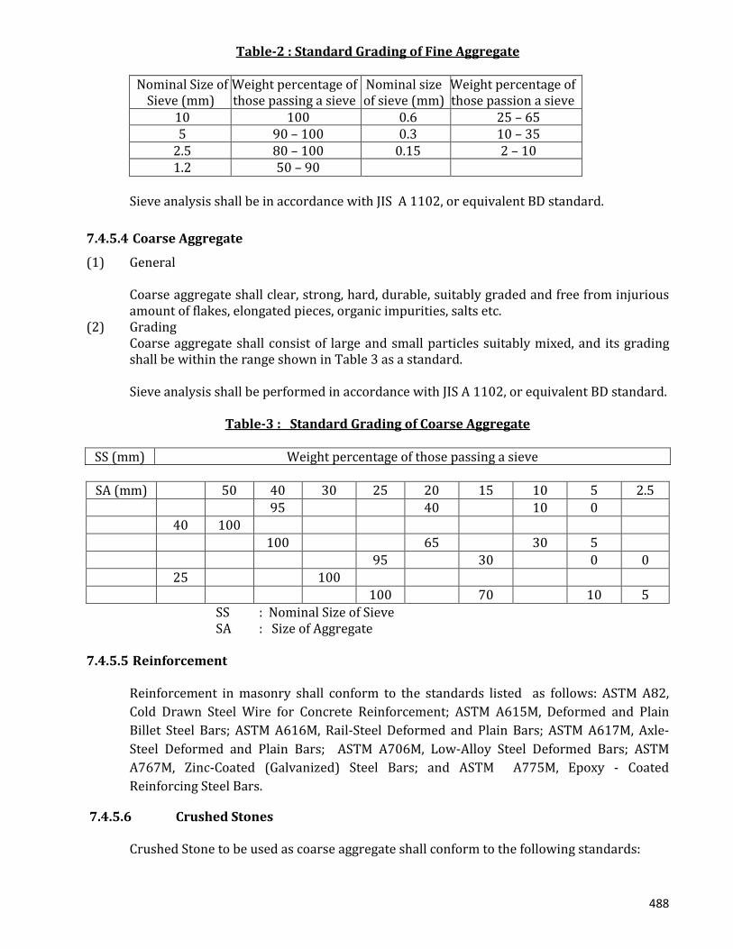
Fine aggregate shall consist of large and small particles suitably mixed, and its grading shall, as a standard, be within the range shown in table 2.
488
Table-2 : Standard Grading of Fine Aggregate
Nominal Size of Sieve (mm)
Weight percentage of those passing a sieve
Nominal size of sieve (mm)
Weight percentage of those passion a sieve
10 100 0.6 25 – 65 5 90 – 100 0.3 10 – 35
2.5 80 – 100 0.15 2 – 10 1.2 50 – 90
Sieve analysis shall be in accordance with JIS A 1102, or equivalent BD standard.
7.4.5.4 Coarse Aggregate
(1) General Coarse aggregate shall clear, strong, hard, durable, suitably graded and free from injurious
amount of flakes, elongated pieces, organic impurities, salts etc. (2) Grading Coarse aggregate shall consist of large and small particles suitably mixed, and its grading
shall be within the range shown in Table 3 as a standard. Sieve analysis shall be performed in accordance with JIS A 1102, or equivalent BD standard.
Table-3 : Standard Grading of Coarse Aggregate
SS (mm) Weight percentage of those passing a sieve
SA (mm) 50 40 30 25 20 15 10 5 2.5 95 40 10 0 40 100 100 65 30 5 95 30 0 0 25 100 100 70 10 5
SS : Nominal Size of Sieve SA : Size of Aggregate 7.4.5.5 Reinforcement
Reinforcement in masonry shall conform to the standards listed as follows: ASTM A82, Cold Drawn Steel Wire for Concrete Reinforcement; ASTM A615M, Deformed and Plain Billet Steel Bars; ASTM A616M, Rail-Steel Deformed and Plain Bars; ASTM A617M, Axle-Steel Deformed and Plain Bars; ASTM A706M, Low-Alloy Steel Deformed Bars; ASTM A767M, Zinc-Coated (Galvanized) Steel Bars; and ASTM A775M, Epoxy - Coated Reinforcing Steel Bars.
7.4.5.6 Crushed Stones Crushed Stone to be used as coarse aggregate shall conform to the following standards:

489
BDS 243 : 1963, Coarse and Fine Aggregates from Natural Sources for Concrete; ASTM C33, Concrete Aggregates; ASTM C330, Lightweight Aggregates for Structural Concrete; ASTM C637, Aggregates for Radiation-Shielding Concrete; ASTM C332 , Lightweight Aggregate for Insulating Concrete; IS: 9142 Artificial Lightweight Aggregates for Concrete Masonry Units.
7.4.5.7 Admixture
Admixtures to be used in concrete shall be subject to prior approval by the Building Official and shall comply with Sec. 2.4.5.1 through 2.4.5.5.
• Chloride : Calcium chloride or admixtures containing chloride from admixture ingredients shall not be used in prestressed concrete, concrete containing embedded aluminum in concrete cast against permanent galvanized metal forms, or in concrete exposed to severe or very severe sulphate-containing solutions (see Sec 5.5.2.1 of Part 6).
• Standards : Air-entraining admixtures shall conform to ASTM C260. Water-reducing admixtures, retarding admixtures, accelerating admixtures, water-reducing and retarding admixtures, and water-reducing and accelerating admixtures shall conform to ASTM C494, Chemical Admixtures for Concrete, or ASTM C1017, Chemical Admixtures for Use in Producing Flowing Concrete.
• Pozzolanas : Fly ash (Pulverized Fuel Ash) or other pozzolans used as admixtures shall conform to ASTM C618.
• Blast Furnace Slag : Ground granulated blast-furnace slag used as an admixture shall conform to ASTM C989.
• Pigment for Coloured Concrete : Pigment for integrally coloured concrete shall conform to ASTM C979.
7.4.6 Storage of Materials
7.4.6.1 Storage of Cement
(1) Cement shall be stored separately for each type in either silos or damp-proof warehouses. (2) Silos to store cement shall be built or equipped with suitable means so that cement will not
be retained at the bottom without being conveyed out. In case of sacked cement, it shall be stacked on the floor rising at least 30 cm from
the surface or the ground, and shall be stored in such a manner as to facilitate conveyance and inspection. Height of each stack shall be at most 13 sacks.
(3) Any portion of Cement which has hardened during its storage shall not be used at all. Cement stored for long period shall be tested for its quality prior to its use.
(4) Cement with excessively high temperature shall be used only after lowering the
temperature. 7.4.6.2 Storage of Aggregate (1) Fine aggregate, coarse aggregate and other aggregate of different type and grading shall be
separately stored between each. (2) When receiving, storing and handling aggregate, facilities shall be well maintained, and
handling shall be carefully performed so that no segregation of large particles from small
490
ones may occur, no foreign materials may become mixed, or in case of coarse aggregate, no particles may be crushed.
(3) Storage facility of aggregate shall be equipped with a suitable drainage system, and shall have a suitable capacity so that the aggregate with uniform surface water may be used and the aggregate received may be used after being tested.
(4) In hot weather, aggregate shall be stored in a place with a facility to avoid direct exposure to the sun etc. so that extreme drying or temperature rise in the aggregate does not occur.
7.4.6.3 Storage of Reinforcement
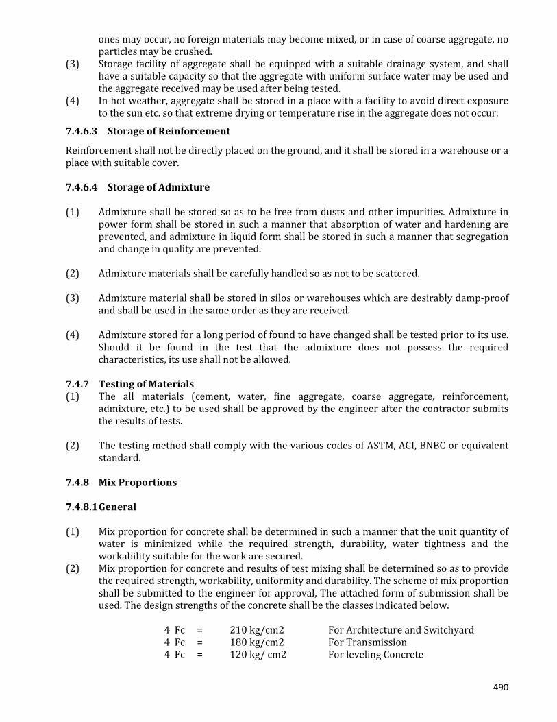
Reinforcement shall not be directly placed on the ground, and it shall be stored in a warehouse or a place with suitable cover. 7.4.6.4 Storage of Admixture (1) Admixture shall be stored so as to be free from dusts and other impurities. Admixture in
power form shall be stored in such a manner that absorption of water and hardening are prevented, and admixture in liquid form shall be stored in such a manner that segregation and change in quality are prevented.
(2) Admixture materials shall be carefully handled so as not to be scattered. (3) Admixture material shall be stored in silos or warehouses which are desirably damp-proof
and shall be used in the same order as they are received. (4) Admixture stored for a long period of found to have changed shall be tested prior to its use.
Should it be found in the test that the admixture does not possess the required characteristics, its use shall not be allowed.
7.4.7 Testing of Materials (1) The all materials (cement, water, fine aggregate, coarse aggregate, reinforcement,
admixture, etc.) to be used shall be approved by the engineer after the contractor submits the results of tests.
(2) The testing method shall comply with the various codes of ASTM, ACI, BNBC or equivalent
standard. 7.4.8 Mix Proportions 7.4.8.1 General (1) Mix proportion for concrete shall be determined in such a manner that the unit quantity of
water is minimized while the required strength, durability, water tightness and the workability suitable for the work are secured.
(2) Mix proportion for concrete and results of test mixing shall be determined so as to provide the required strength, workability, uniformity and durability. The scheme of mix proportion shall be submitted to the engineer for approval, The attached form of submission shall be used. The design strengths of the concrete shall be the classes indicated below.
4 Fc = 210 kg/cm2 For Architecture and Switchyard 4 Fc = 180 kg/cm2 For Transmission 4 Fc = 120 kg/ cm2 For leveling Concrete

491
Where 4 Fc means concrete compressive strength at the age of 28 days. Basic design date for mixing are indicated in the table herein.
Table – 4 : Basic Mix Data
Class Design strength 4Fc (kg/cm2)
Maximum size of
aggregate(mm)
Slump (cm)
Air entertainment
(%)
E 210 25 10 – 15 4 1 Architecture Switchyard
B 180 40 10 – 15 4 1 Transmission C 120 40 10 – 15 4 1 Leveling Concrete
Note : 1. Specific gravity in design Cement – 3.15, Fine Aggregate – 2.62, COARSE Aggregate and Crushed Stones – 2.62 2. Relationship between C/W (Cement water ratio) and maximum compressive strength at 28
days. ø 28 = 210 + 215 C/W
Concrete Mix Design Report Quantity (per mixed 1 m3) (kg/m3) Maximum size or aggregat
e (mm)
Slum Air
entrain-ment
(%)
Maximum
water/ cement
W/c (%)
Sand percen-tage S/a (%)
Water W
Cement C
Fi
Coarse aggreg
ate
Admixtures
mm-mm
mm-mm
7.4.9 Batching and Mixing 7.4.9.1 Batching (1) General Each material to be used in concrete is obtained. (2) Batching Equipment
(a) Batching method and batching equipment for each material shall be subject to the approval of the engineer in advance.
(b) Batching equipment for each material shall be inspected and adjusted, if necessary,
prior to the commencement of the construction work and periodically during the construction.
(3) Batching of materials

492
(a) Batching shall be made in accordance with the job mix. Test for surface water of the
aggregate shall be in accordance with ASTM or equivalent or as directed by the engineer. Test for the quantity of the effective absorption of water, in case of dried effective absorption of water, shall be as directed by the engineer.
(b) Volume of one batch shall be determined as directed by the engineer. (c) Each material shall be batched by weight for each batch except the water and the
solution of admixture, which may be measured by volume. (d) Error in the measurement in each batch shall be at most the values given in Table 5.
Table-5 : Allowable Error in Measurements
Type of Materials Permissible Error (%)
Water 1 Cement &Admixture Material 2 Aggregate 3 Solution of Admixture Agent 3
7.4.9.2 Mixing
All concrete shall be mixed thoroughly until there is a uniform distribution of materials and shall be discharged completely before the mixer is recharged.
Ready mixed concrete shall be mixed and delivered in accordance with the requirements of "Specification for Ready Mixed Concrete" (ASTM C94) or "Specification for Concrete Made by Volumetric Batching and Continuous Mixing" (ASTM C685).
Job mixed concrete shall be mixed in accordance with the following:
a) Mixing shall be done in a batch mixer of approved type.
b) Mixer shall be rotated at a speed recommended by the manufacturer.
c) Mixing shall be continued for at least 90 seconds after all materials are in the drum, unless a shorter time is shown to be satisfactory by the mixing uniformity tests of "Specification for Ready Mixed Concrete" (ASTM C94).
d) Materials handling, batching, and mixing shall conform to the applicable provisions of "Specification for Ready Mixed Concrete" (ASTM C94).
e) A detailed record shall be kept to identify:
i) number of batches produced;
ii) proportions of materials used;
iii) approximate location of final deposit in structure;
iv) time and date of mixing and placing.
(1) General
493
Materials for concrete shall be thoroughly mixed until the mixed concrete becomes uniform in quality.
(2) Mixers
(a) Mixers shall be either tilting batch mixers or forced batch mixers. (b) Any concrete mixers to be used under this project shall be subject to approval of the
engineer. (c) Mixers shall be such that they will not cause any separation of materials at the time of
discharging. (3) Mixing
(a) When charging a mixer, all the materials shall be charged uniformly and simultaneously in principle.
(b) Mixing time shall, in principle, be determined based on tests. As a standard, it shall be
at least 1 minute and 30 seconds for tilting type misers and 1 minute for forced mixers.
(c) Mixing shall not be continued for more than three times the specified mixing time. (d) Materials for new batch shall not be charged into the mixer until all the concrete in the
mixer is discharged. (e) Mixers shall be thoroughly cleaned before and after their use. (f) Concrete left as mixed and commenced setting shall not be used after re-tempering.
7.4.10 Conveying and Placing (1) Prior to the commencement of the construction work, a plan of conveying and placing shall
be made and this shall be subject to the approval of the engineer. (2) Concrete shall be conveyed by methods which will minimize separation and loss of
materials, shall be placed immediately and then shall be thoroughly compacted. Even when it is impossible to place the concrete immediately due to some special reasons, the time between mixing and the completion of placing shall not exceed 45 minutes.
During the waiting period, the concrete shall be protected against direct exposure to the sun, wind and rain, and the concrete left for a relatively long time shall be re-mixed without adding my water. No portion of concrete which has started to harden shall be used.
(3) When extreme separation is observed in concrete during its delivery or placement, it shall
be made uniform in quality by re-mixing. 7.4.10.1 Conveying (1) Conveying Equipment to be used in conveying concrete shall be those which can easily deposit.
Should the delivery distance be long, they shall be equipped with such facility as an agitator.

494
(2) Buckets Structure of buckets shall be such that they will not cause any separation of
materials when charging or discharging concrete and that the concrete can be easily and swiftly deposited from them.
(3) Belt Conveyors Should belt conveyors be used, they shall be suitably located so that they will be
suitably located so that they will not impair the quality of the concrete and the end of the line shall be provided with baffle plates and an elephant trunk so that the separation of materials can be prevented.
(4) Buggies and Trolleys Should buggies or trolleys be used, a level runway or path shall be constructed so
that separation of materials will not occur in conveying concrete. (5) Chutes
(a) Should any chute be used, it shall be a drop chute in principle. The drop chute shall be connected to an elephant trunk so that the separation of materials is minimized.
(b) Open chutes may be used, only when approved by the Engineer. Each open chute shall
be inclined at uniform angle all along its length, and the slope shall be such that it will not cause any separation of materials of the concrete to be placed. The distance between the bottom end of the chute and the surface on which concrete is to be deposited shall be at most 1.5m. the discharging end shall be equipped with a suitable elephant trunk.
7.4.10.2 Placing (1) Preparation
(a) Prior to the placement, the arrangement of reinforcement, forms etc. shall be approved by the engineer.
(b) Prior to the commencement of the placement, it shall be certified that conveying
equipment and placing equipment are in conformance to the plan of placing specified in Clause-______
(c) Prior to the placement, conveying equipment, placing equipment and the inside of
forms shall be thoroughly cleaned to prevent foreign materials from being mixed into the concrete. Portions expected to face concrete and to absorb water shall be moistened in advance.
(d) Water in pits and sumps shall be removed prior to the placement of the concrete.
Suitable protective measures shall be taken so that water running into these pits and sumps will not wash the concrete just placed.
495
(2) Placing
(a) Concrete shall be placed in accordance with the plan of placing specified in Clause-_____should it be inevitable to change the placing method, it shall be so done as directed by the Engineer.
(b) When concerning is done in hot weather, special attention shall be given to the
materials, placement, curing etc. (c) Portions such as the ground and foundations which may absorb the water in
concrete shall be thoroughly wetted prior to the placement of concrete. (d) Temperature in concrete at the time of placing shall be at most 35o C. (e) Conveying equipment for concrete shall be such that they will protect concrete from
being dried or heated. (f) Concrete shall be protected as soon as the placement is completed or interrupted.
Special care shall be exercised to keep the surface of the concrete moist. (g) During the concerning operation, attention shall be paid not to disturb the
arrangement of the reinforcement. (h) Concrete shall be embedded into concrete with abundant mortar. Should any
notable separation of materials be observed during concerning, the concrete shall be remised to obtain the uniform quality and necessary measures to prevent separation shall be taken before the placing operation is resumed.
(i) Concrete for one section shall be placed continuously until it is completed. (j) Concrete shall, in principle, be placed in such a manner that the surface of the placed
concrete will be horizontal within the section. One lift in placement shall be at most 40 cm, in principle.
(k) Should concrete be placed in layers, each succeeding layer shall be placed while the
one below it is still plastic. Should it become necessary to place concrete on top of a layer which has started setting, it shall be done in accordance with Clause 4.10.
(l) When height of the form work is great, it shall be provided with openings for
concrete placing, or the placement shall be done using from chutes in order to prevent the concrete from being segregated or from adhering to the reinforcement or to the forms above the layer to be placed.
(m) The height of the end of buckets and hoppers shall be at most 1.5 m above the level
of placement. (n) Should there by any water coming out and accumulated during the placement, the
concrete shall not be placed further until the water is removed by a suitable means. (o) When concerning high structures such as walls and columns continuously, the
consistency of the concrete and the rate of lifting shall be controlled in such a

496
manner that separation of materials during the placement and the compaction is minimized.
7.4.11 Compaction (1) In principle, internal vibrators shall be used to compact the concrete. When it is difficult to
use internal vibrators in the case of thin walls, form vibration shall be used. (2) Vibrators to be used shall be subject to the approval of the engineer. (3) Concrete shall be thoroughly compacted immediately after placement and shall be
thoroughly worked around the reinforcement and into the corners of the form. Where conditions take compaction difficult, batches of mortar containing the same proportions of cement, sand and water as used in the concrete shall first be deposited to certify the compaction.
(4) When compaction is achieved by vibrators, it shall be inserted into the layer below the one
just placed by about 10cm. The vibrators shall be pulled out very slowly so that no hole will form in the concrete.
(5) When concerning is to be compacted by internal vibrators, the spacing and the time of their
application shall be as directed by the engineer.
7.4.12 Additional Placing
Should additional placing be made on top of a layer which has already started to harden, it shall be thoroughly and carefully worked on as directed by the engineer so that the top and the lower layer becomes monolithic. (1) Wet Curing.
(a) Concrete, after being placed, shall be sufficiently cured without being subjected to injurious effects caused by low temperature, drying, sudden change in temperature, etc.
The contractor shall report the said method to the engineer and obtain his approval. (b) Concrete shall be protected from vibrations, impacts and loads while it is hardening.
(2) Wet Curing
(a) Concrete being placed and compacted shall be protected from the sun, wind, showers etc.
(b) Any exposed surface of concrete which has hardened to a degree that works can be
done without impairing it shall be either covered with wet mats, canvas, sand etc. or directly watered, and shall be kept moistened continually for at least 5 days after the placement in case ordinary Portland cement is used.
(c) When sheathing boards are expected to become dry, they shall be watered.

497
7.4.13 Joints (1) General
(a) Location and structure of joints as shown and specified in the drawings shall be observed.
(b) Should any joint not specified in the design be made, its location, direction and
method of construction shall be determined in the plan of construction so that it will not impair the strength and the appearance of the structure, and this shall be subject to the approval of the engineer.
(2) Construction Joints
(a) Construction joints shall be located where the shear acting there is as small as possible, and with their face in perpendicular, in principle, to the direction of compression in the member.
(b) Should it be unavoidable to make a construction joint at a location where large shear
is action, it shall be reinforced by forming tenors or grooves, or embedding suitable steel.
(3) Construction of Horizontal Construction Joints
(a) Sided of the surface of a horizontal construction joint intersecting the forms shall be kept as horizontal and straight as possible.
(b) When new concrete is placed, the surface of the old concrete shall be removed of all
laitance, interior concrete, loosened aggregate, etc. and shall be thoroughly wetted. (c) Prior to the placement of new concrete, the forms shall be tightened, and either
cement paste or mortar with the same mix proportions as in concrete shall be applied on the surface of the old concrete.
The concrete shall then be placed immediately and shall be compacted so that is will
be in tight contact with the old concrete. (4) Construction method for Vertical Construction Joints
(a) When a vertical construction joint is to be made, the forms at the joint shall be rigidly supported, and the concrete in the vicinity of the point shall be thoroughly compacted by vibrators.
(b) Fresh concrete shall be placed after the surface of the aged concrete at the joint is
removed of the surface film or is roughened and thoroughly wetted, followed by the application of cement paste or mortar, or after the surface is treated as directed by the engineer.
(c) Fresh concrete shall be thoroughly compacted at the time of placement so that the
fresh and the aged concrete is in tight contact with each other.
498
It is recommended that the new concrete be compacted again after a suitable delay by applying vibration.
7.4.14 Reinforcement Works 7.4.14.1 Processing of Reinforcement (1) Reinforcement shall be processed to the shape and the dimension as shown in the drawings
by a method which will not impair the quality of the material. (2) Reinforcement shall be processed in ordinary temperature. When it is unavoidable to heat
for processing, the whole process shall be subject to the approval of the engineer. 7.4.14.2 Fabrication of Reinforcement (1) Prior to fabrication, reinforcement shall be thoroughly cleaned and free from loose rust and
any other material which may impair the bond between the reinforcement and the concrete.
(2) Reinforcement shall be placed to the designated position, and shall firmly be fabricated so
that it will not be dislocated ruining the placement of concrete. Erection bars, if required, shall be used for this purpose.
Important crossings of reinforcement shall be fastened by either annealed wire of at
least 0.9mm in diameter. (3) Clearance between reinforcement and sheathing board shall be maintained correctly by use
of spacers. (4) Reinforcement shall be always inspected by the engineer after the completion of
fabrication. 7.4.14.3 Joints of Reinforcement (1) Lap joints of reinforcement shall be made by lapping the required lengths and fastening
them together at several points with annealed wire of at least 0.9mm in diameter. (2) Reinforcement projecting form the structure and exposed for future jointing shall be
protected from damage, corrosion, etc. 7.4.15 Forms and Timbering Forms and timbering shall be so designed and constructed as to have the required strength and rigidity, to secure correct position, shape and dimension of the structure and to secure the satisfactory quality in concrete. 7.4.15.1 Materials Materials to be used for the form and the timbering shall be selected based on the strength, rigidity, durability workability, effect on the concrete to be placed.
499
7.4.15.2 Design of Forms (1) Forms shall be those which can easily be fabricated and stripped; joints of sheathing boards
and panels shall be forced in parallel with or perpendicular to the axis of the member so that it will have a structure which is tight against mortar.
(2) The structure of form shall be such that the corners of concrete can be moulded even when
it is not particularly specified. (3) Temporary openings, if necessary, shall be made at suitable locations to facilitate cleaning
and inspection of the forms and the placing of concrete. 7.4.15.3 Design of Timbering (1) Suitable types of timbering shall be selected and the load carried by them shall be correctly
transferred to the foundation by appropriate means. (2) As for the timbering for important structures, design drawings shall be prepared by they
shall be subject to the approval of the engineer. 7.4.15.4 Construction of Forms
Stripping agents shall be applied on the inside of the sheathing board. 7.4.15.5 Construction of Timbering (1) Timbering shall be constructed so as to have sufficient strength and stability. (2) An amount of the settlement of the form words due to the weight of the placed concrete
shall be estimated and a chamber shall be introduced, if necessary, in the shoring. 7.4.15.6 Inspection of Forms and Timbering (1) Forms and timbering shall be inspected by the Engineer prior to the placement of contents. (2) Condition of forms and timbering shall be inspected during the placement of concrete. 7.4.5.7 Removal of Forms and Timbering (1) Forms and timbering shall not be removed until the concrete reaches a strength required to
carry the concrete weight and the load applied during the construction work. (2) Time and sequence of the removal of the removal of the forms and timbering shall be
subject to the approval of the engineer. 7.4.15.8 Loading on a Structure Immediately After Removal of Forms and Timbering Loading on a structure immediately after the removal of the forms and timbering shall be subject to the approval of the engineer.
500
7.4.16 Finishing 7.4.16.1 General When the uniform appearance should be obtained on the exposed surface, special attention shall be given to place the concrete for the predetermined section continuously without changing the materials, proportions and the method of the placement. 7.4.16.2 Surface Not Facing Sheeting Boards (1) Surface of the concrete compacted and approximately leveled to the required level and
shape shall not be finished until the water coming out ceases or is removed. (2) Cracks formed after finishing but before hardening shall be removed by tamping or re-
finishing. 7.4.6.3 Surface Facing Sheathing Boards (1) Concrete which will be exposed shall be placed and compacted in such a manner that the
surface solely composed of mortar will be secured. (2) Projections and lines formed on the surface of concrete shall be removed to ensure surface
flatness. Honeycombs and chipped places shall be removed and the surface and the surface shall be moistened and patched with appropriately proportioned concrete or mortar to be finished flat.
(3) Cracks formed after the removal of the forms due temperature stress, drying shrinkage, etc.
shall be repaired as directed by the Engineer. 7.4.17 Quality Control and Inspection 7.4.17.1 General Materials of concrete, reinforcement, equipment’s and workmanship shall be controlled produce reinforced concrete of the required quality economically. 7.4.17.2 Tests of Concrete
(1) During construction, the following tests shall be carried out as directed by the Engineer. (2) Air test (3) Compression test of concrete. (4) Others 7.4.17.3 Inspection of Forms and Timbering (1) Forms and timbering shall be inspected by the Engineer Prior to the placement of contents. (2) Condition of forms and timbering shall be inspected during the placement of concrete. 7.4.17.4 Removal of Forms Timbering (1) Forms and timbering shall not be removed until the concrete reaches a strength required to
carry the concrete weight and the load applied during the construction work.
501
(2) Time and sequence of the removal of the forms and timbering shall be subject to the approval of the Engineer.
7.4.17.4 Loading on All Structure Immediately after Removal of Forms and Timbering
Loading on a structure immediately after the removal of the forms and timbering shall be subject to the approval of the Engineer.
7.4.18 Finishing
7.4.18.1 General When the uniform appearance should be obtained on the exposed surface, special attention shall be govern to place the concrete for the predetermined section continuously without changing the materials, proportions and method of the placement. 7.4.18.2 Surface Not Facing Sheathing Boards (1) Surface of the concrete completed and approximately leveled to the required level and
shaper shall not be finished until the water coming out ceases or is removed. (2) In order to determine the suitability of the curing method and the time to remove the
forms, and in order to certify the safety for early loading, strength tests shall be preformed on specimens cured under the conditions as similar as possible to those of the concrete at the site.
Should the result of the test indicate that the obtained strength of the specimen is
much smaller than that of the specimens cured under the control condition, the method of curing at the site shall be changed as directed by the Engineer.
(3) For Compression test of concrete, six (6) test specimens shall be required for each concrete.
Three (3) specimens shall be tested for seven (7) or fourteen (14) days strength, the remained three(3) specimens shall be tested for twenty- eight (28) days strength.
The expense for the above tests shall be included is the unit prices. (4) Should it become necessary after the completion of the work, non- destructive test of
concrete or tests on concrete specimens cut from the structure shall be carried out. 7.4.18.3 Test of Reinforcement Bars In the case where there is no test certificate of reinforcement bars (mill sheet) or incase the Engineer deems necessary, the contractor shall carry out the characteristics test of reinforcement bars and obtain an approval of the Engineer. 7.4.18.4 Test Method Test method shall conform the those specified in ASTM, ACI, BNBC or equivalent, unless directed otherwise by the Engineer. 7.4.18.5 Report The result of the tests shall be reported to the Engineer without delay. 7.4.18.6 Control of Concrete by Compressive Strength

502
(1) Control of concrete by compressive strength shall generally be based on 28 days
compressive strength. Specimens, in this case, shall be taken in such a manner that they will represent the concrete of the structure.
(2) Test results of compressive strength to be used for the control of concrete shall generally be
obtained by averaging the compressive strength specimens taken from the same batch. (3) Should the quality of concrete be controlled by the test results, it shall be use the control
test. 7.4.18.7 Inspection of Quality of Concrete (1) The contractor shall submit to the Engineer the results of Inspection of Quality of concrete
obtained according to the quality control test in the preceding Paragraph 8.16.6 and obtain and approval of the Engineer.
(2) Should it be found in the inspection that the quality of the concrete is not suitable, remedial
measures such as modifying the mix proportions, performance tests of equipment’s and facilities, improvement of the working method, etc. shall be taken. The concrete placed in the structure shall be checked if it can perform the designated function and the suitable measures, should it become necessary as directed by the Engineer.
7.4.19 Inspection of Structures Structures shall be inspected after their completion as directed by the engineer. • Brick Masonry Work Prior to commencing the brick masonry work, the surface of brick shall thoroughly be cleaned and sufficiently moistened in order to ensure smooth adherence of mortar to the brick surface. 7.4.20 Road Work The Construction work of roads shall be carried out in accordance with the Drawing. However, demolition and restoration of the public roads (including private roads) shall be carried out according to the specifications designated the official in charge of road management not with standing the provisions described in the specifications and the Drawing. 7.4.20.1 Road Work Inside The Premises (1) Sub –grade
a) Any excavation and banking work required for sub-grade construction shall be carried out in accordance with the respective provisions in General Provision SECTION-2 : EARTH WORKS.
b) The material required for banking and displacement shall be so placed that the finished thickness of one layer after compaction will become 20 cm or less.
c) The sub-grade surface shall be finished by proof- rolling in order to obtain the contact
pressure sufficient to permit smooth traffic of vehicles of 8 tons or over should any
503
defects be detected as a result of proof-rooling, such detective sub-grade surface shall be finished again to the satisfaction of the Engineer.
d) The finished sub-grade surface shall be within + 5 cm of the design elevation.
(2) Sub base Course (a) The materials to be used for sub base course shall be in accordance with the
specification described in the Drawing. The Contractor shall submit a report concerning the quality of materials and the methods of sampling to the Engineer for approval.
(b) The finished surface of sub base course shall be within –10 mm and + 5mm of the
design elevation.
(3) Surface Course (Asphalt pavement)
(a) Prior to commencing pavement, the sides of concrete side walk, manhole, etc. shall be cleaned, and molten asphalt, etc. shall be coated over the sides.
(b) The surface to be seal-coated and prime- coated shall be finished into even level, and after perfecting removing any bloc, dust and other foreign matters, such surface shall be cured and dried.
(c) The mixtures shall be spread uniformly, rolled and finished into the specified thickness. Then, the finished surface shall be measured in parallel to the center line of the load by using a 3 m straight line ruler. In this case, the depth of any concise sections shall not exceed 5 mm.
(d) The Contractor shall submit a report on the materials to be used for pavement of surface course and method therefore to the Engineer to the Engineer for approval.
(4) Inspection
The Contractor shall receive inspection of the Engineer during the course and after completion of sub base course and surface course works.
7.4.20.2 Public Road (Including Private Road)
(1) Demolition of Pavement Demolition of Pavement for public roads including private roads shall be carried out
so carefully as not to cause any hazardous effect upon the surrounding portions of cement, concrete or pavement.
(2) Road Keeping and Restoration
(a) The road keeping shall be of a construction applicable to the prevailing site conditions
and so provided as not to cause any danger or trouble against traffic. (b) The contractor shall submit the drawings for road keeping to the Engineer for
approval. (c) The Contractor shall constantly patrol any spots of road keeping and exert his utmost
efforts perform maintenance and repair of such roads in order to eliminate any trouble against smooth traffic.
504
(d) The Contractor shall carry out maintenance and repair of any pertinent roads so carefully as not to cause any trouble against smooth traffic until the said roads have been restored and taken over to the official in charge of road management.
7.4.21 Drainage Work
(a) The drainage work shall be as described in the Drawing and carried out in accordance with General Provision SECTION-2 : EARTH WORK AND SECTION-3 : REINFORCED CONCRETE WORK.
(b) The water – plumbing facility for drainage shall be of such a construction as not to
cause any trouble against the surrounding area and structure. The contractor shall submit the design and execution schedule for the water plumbing work to the Engineer for approval.
7.4.22 Painting Work 7.4.22.1 General This clause covers all painting applied to surface of plaster wood, and metal indicated in the Drawing. No painting shall be applied to surfaces of stainless steel copper, bronze, brass or any/all steel in contact with concrete. Painting work shall be performed by skilled workmen. Selection of color shall be as determined by the Engineer, unless otherwise specified. 7.4.23 Materials and Painting Coat 7.4.23.1 Materials Materials to be used in this clause shall be as follows and shall conform PAINTS AND VARNISHES
• Water Based Paints
Water based paints shall conform to the following standards:
BDS 500:1965 Specification for Distemper Dry (under revision);
BDS 1097:1984 Specification for Plastic Emulsion Paint.
Part I for Interior Use;
Part 2 for Exterior Use;
IS 5410-1969 Specification for Cement Paint, Colour as Required;
IS 428-1969 Specification for Distemper, Oil Emulsion, Colour as Required
• Ready Mixed Paint and Enamels
Ready mixed paints and enamels shall conform to the following standards:
BDS 13:1960 Specification for Ready Mixed Paints, Varnish, Lacquers and Related Products (under revision);

505
BDS 14:1960 Specification for Black Bituminous Paint, Brushing for General Purposes (under revision);
BDS 397:1964 Specification for Ready Mixed Paint, Brushing, Red Oxide Zinc Chrome, Priming (under revision);
BDS 398:1964 Specification for Ready Mixed Paint, Spraying, Red Oxide Zinc Chrome, Priming (under revision);
BDS 399:1964 Specification for Aluminum Paint, Spraying for General Purposes, in Dual Container (under revision);
BDS 400:1964 Specification for Aluminium Paint, Brushing, for General Purposes in Dual Container (under revision);
BDS 401:1964 Specification for Varnish, Finishing, Exterior, Type-I, (Synthetic) (Tentative) (under revision);
BDS 402:1989 Specification for Ready Mixed Paint, Brushing, Finishing, Semigloss, for General Purposes (First Revision);
BDS 499:1965 Specification for Ready Mixed Paints, Brushing, for Road Marking (white, yellow and black) (under revision);
BDS 616:1966 Specification for Enamel, Brushing, Exterior (i) Undercoating, (ii) Finishing, Colour as Required (under revision);
BDS 617:1966 Specification for Enamel, Brushing, Interior (i) Undercoating, (ii) Finishing, Colour as Required (under revision);
BDS 926:1980 Specification for Ready Mixed Paint, Brushing, Petrol Resisting, Air Drying, for Exterior Painting of Containers, Colour as Required;
BDS 927:1980 Specification for Ready Mixed Paint, Brushing, Petrol Resisting, Air Drying, for Interior Painting of Tanks and Containers, Red Oxide (colour unspecified);
BDS 928:1980 Specification for Ready Mixed Paint, Brushing, Acid Resisting, for Protection Against Acid Fumes, Colour as Required;
BDS 973:1981 Specification for Specification and Methods of Test for Linseed Stand Oil for Paints and Varnishes;
BDS 974:1981 Specification and Methods of Test for Raw Tung Oils for Paints and Varnishes;
BDS 1005:1981 Specification for Ready Mixed Paint, Brushing, Finishing, Stoving, Enamel, Colour as Required;
506
BDS 1141:1986 Specification for Ready Mixed Aluminium Priming Paints for Woodwork;
BDS 1151:1986 Specification for Pavement Marking Paints.
7.14.3 Thinners and Solvents
These shall conform to the following standards:
IS 324-1959 Specification for Ordinary Denatured Spirit (revised);
IS 533-1973 Specification for Gum Spirit of Turpentine (Oil of Turpentine) (First Revision);
IS 82-1973 Methods of Sampling and Test for Thinners and Solvents for Paints (First Revision).
• Varnishes and Lacquers
These materials shall conform to the following standards:
BDS 401:1964 Specification for Varnish, Finishing, Exterior, Type-I, (synthetic) (under revision);
BDS 1064:1983 Specification for Varnish, Staving;
BDS 1065:1983 Specification for Varnish, Acid Resisting;
BDS 1066:1983 Specification for Varnish, Finishing, Interior;
IS 197-1969 Methods of sampling and Test for Varnishes and Lacquers (First Revision);
IS 340-1978 Specification for Varnish, Mixing (First Revision);
IS 346-1952 Specification for Varnish, Spirit, Clear, Hard;
IS 347-1975 Specification for Varnish, Shellac for general purposes (First Revision);
IS 348-1968 Specification for French Polish (First Revision);
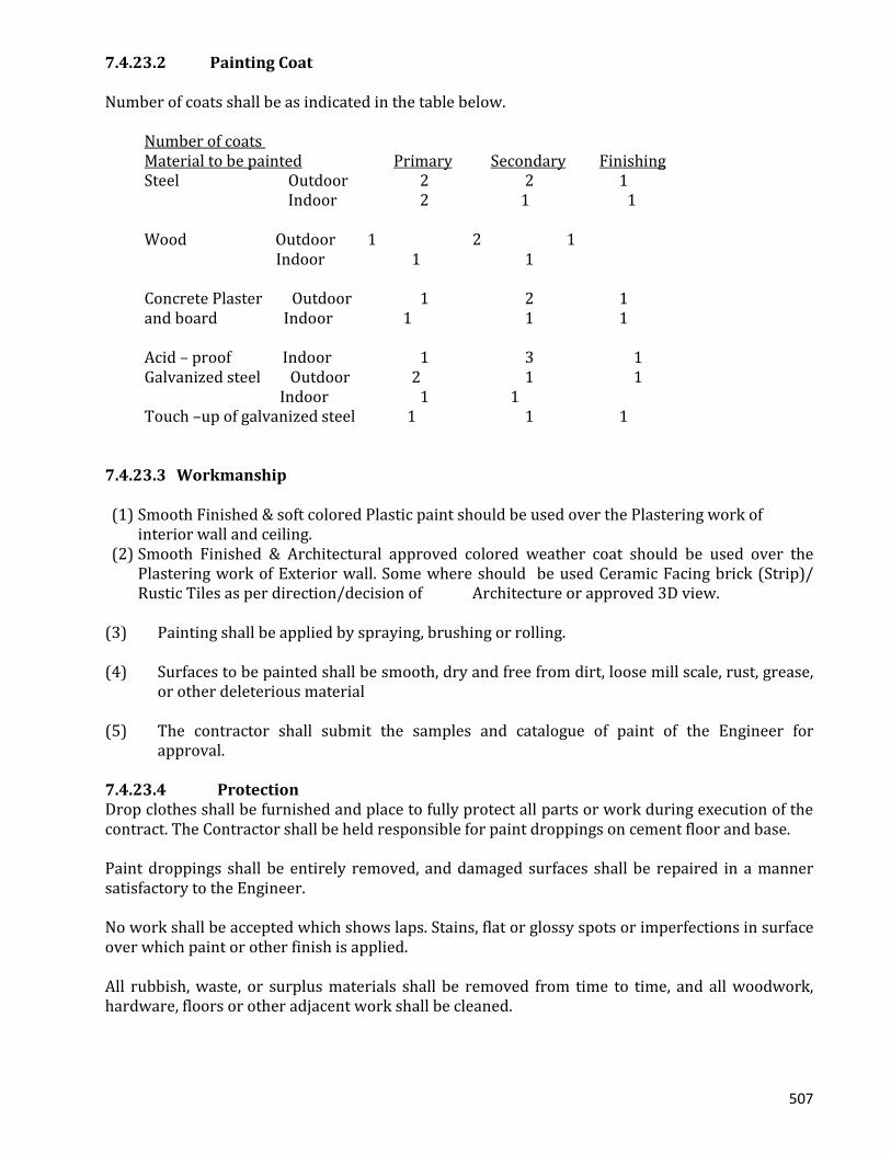
507
7.4.23.2 Painting Coat Number of coats shall be as indicated in the table below.
Number of coats Material to be painted Primary Secondary Finishing Steel Outdoor 2 2 1 Indoor 2 1 1 Wood Outdoor 1 2 1 Indoor 1 1 Concrete Plaster Outdoor 1 2 1 and board Indoor 1 1 1 Acid – proof Indoor 1 3 1 Galvanized steel Outdoor 2 1 1 Indoor 1 1 Touch –up of galvanized steel 1 1 1
7.4.23.3 Workmanship
(1) Smooth Finished & soft colored Plastic paint should be used over the Plastering work of
interior wall and ceiling. (2) Smooth Finished & Architectural approved colored weather coat should be used over the
Plastering work of Exterior wall. Some where should be used Ceramic Facing brick (Strip)/ Rustic Tiles as per direction/decision of Architecture or approved 3D view.
(3) Painting shall be applied by spraying, brushing or rolling. (4) Surfaces to be painted shall be smooth, dry and free from dirt, loose mill scale, rust, grease,
or other deleterious material (5) The contractor shall submit the samples and catalogue of paint of the Engineer for
approval. 7.4.23.4 Protection Drop clothes shall be furnished and place to fully protect all parts or work during execution of the contract. The Contractor shall be held responsible for paint droppings on cement floor and base. Paint droppings shall be entirely removed, and damaged surfaces shall be repaired in a manner satisfactory to the Engineer. No work shall be accepted which shows laps. Stains, flat or glossy spots or imperfections in surface over which paint or other finish is applied. All rubbish, waste, or surplus materials shall be removed from time to time, and all woodwork, hardware, floors or other adjacent work shall be cleaned.

508
All glass throughout the building shall have all paint or varnish sports and brush marks removed, and upon completion of the painting work, all glass that is scratched or damaged by the painter’s work, shall be replaced at the contractor’s responsibility. Hardware and other unpainted metal surfaces shall be cleaned. CONTROL BUILDING 7.4.24 Temporary Work, Earth Work and Piling Work 7.4.24.1 General The work of the above items shall be specified in clauses “TEMPORARY WORK”, “EARTH WORK” and “PILING WORK” in Section 1 “GENERAL PROVISIONS”, unless otherwise specified. 7.4.24.2 Materials of Pile The pile to be used for Control Building shall be steel pipe pile (406.4 x 6.4) 7.4.25 Concrete Work 7.4.25.1 General Concrete work shall be as specified in Clause “CONCRETE WORK” in SECTION 1 “GENERAL PROVISIONS”, unless otherwise specified. 7.4.25.2 Classification of Materials to Be Used for Buildings 7.4.25.2.1 Concrete The classification to be used for structural concrete shall be 4 Fc= 210 kg/cm2 concrete. (class E 210-10-25) The classification to be used for leveling concrete shall be 4 Fc = 120 kg/ cm2 concrete. (class C 120-10-40) 7.4.25.2.2 Reinforcing Bar
Reinforcement and welding of reinforcement to be placed in concrete shall conform to the requirements of this section.
a) Deformed Reinforcement : Deformed reinforcing bars shall conform to the following standards; BDS 1313, Steel Bars and Wires for Reinforcement of Concrete; BDS 580, Rolled Deformed Steel Bars (intermediate grade) for Concrete Reinforcement; Reinforcement conforming to the ASTM, Standards: A615M, Deformed and Plain Billet-Steel Bars; A616M, Rail-Steel Deformed and Plain Bars; A617M, Axle-Steel Deformed and Plain Bars; A706M, Low-Alloy Steel Deformed Bars; A767M, Zinc Coated (Galvanized) Steel Bars; and A775M, Epoxy-Coated Reinforcing Steel.
b) Deformed reinforcing bars with a specified yield strength f y( ) exceeding 410 MPa may
be used, provided f y shall be the stress corresponding to a strain of 0.35 per cent and the bars otherwise conform to ASTM standards noted above. Fabricated deformed steel bar mats conforming to ASTM A184M and deformed steel wire complying with ASTM

509
A496 may be used. Deformed wire for concrete reinforcement shall not be smaller than size D4 (Nominal diameter : 5.72 mm), and for wire with a specified yield strength f y , exceeding 410 MPa f y shall be the stress corresponding to a strain of 0.35 per cent.
Welded deformed steel wire fabric conforming to ASTM A497 may be used; for a wire with a specified yield strength
f y( ) exceeding 410 MPa, f y shall be the stress
corresponding to a strain of 0.35 per cent. Welded intersections shall not be spaced farther apart than 400 mm in direction of calculated stress, except for wire fabric used as stirrups.
7.3.25.2.3 Form 7.4.25.2.3.1 Form Oil Form oil shall be light colored paraffin oil or other acceptable non-staining material. Form in contact with concrete shall be given a uniform light spray coating of the specified form oil coating in accordance with the manufacturer’s recommendations. Form coating shall be applied to the forms before they are set. 7.4.25.2.3.2 Form Ties Form ties shall have sufficient strength, stiffness and rigidity to support and maintain the form in proper position and alignment without the use of auxiliary spreaders. The type of form ties used shall be submitted to the Engineer for approval. 7.4.26 Steel Reinforcement 7.4.26.1 Lapped Splices in Reinforcement Splices at points of great stress shall be avoided wherever possible, and care shall be exercised to avoid concentration of splices at one place. a) Length of Lap The lengths of laps in lapped splices shall be in accordance with the Drawings and indicated
below. 40 d without hook 35 d with hook The length of lap in a lapped splice of reinforcing bars of different diameters shall be based
on the nominal diameter of smaller bar. 7.4.26.2 Anchorage of Reinforcement
The length of anchorage of reinforcement shall be determined in accordance with the type of reinforcing bar, the grade of concrete and type of stress acting on the reinforcement, and shall be as indicated in the table below, unless otherwise indicated.
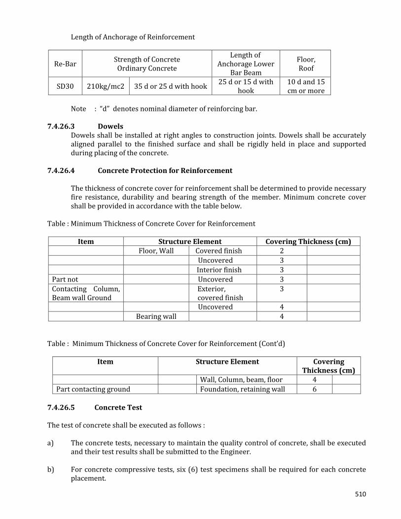
510
Length of Anchorage of Reinforcement
Re-Bar Strength of Concrete Ordinary Concrete
Length of Anchorage Lower
Bar Beam
Floor, Roof
SD30 210kg/mc2 35 d or 25 d with hook 25 d or 15 d with hook
10 d and 15 cm or more
Note : “d” denotes nominal diameter of reinforcing bar. 7.4.26.3 Dowels Dowels shall be installed at right angles to construction joints. Dowels shall be accurately
aligned parallel to the finished surface and shall be rigidly held in place and supported during placing of the concrete.
7.4.26.4 Concrete Protection for Reinforcement The thickness of concrete cover for reinforcement shall be determined to provide necessary
fire resistance, durability and bearing strength of the member. Minimum concrete cover shall be provided in accordance with the table below.
Table : Minimum Thickness of Concrete Cover for Reinforcement
Item Structure Element Covering Thickness (cm) Floor, Wall Covered finish 2 Uncovered 3 Interior finish 3 Part not Uncovered 3 Contacting Column, Beam wall Ground
Exterior, covered finish
3
Uncovered 4 Bearing wall 4
Table : Minimum Thickness of Concrete Cover for Reinforcement (Cont’d)
Item Structure Element Covering Thickness (cm)
Wall, Column, beam, floor 4 Part contacting ground Foundation, retaining wall 6
7.4.26.5 Concrete Test The test of concrete shall be executed as follows : a) The concrete tests, necessary to maintain the quality control of concrete, shall be executed
and their test results shall be submitted to the Engineer. b) For concrete compressive tests, six (6) test specimens shall be required for each concrete
placement.
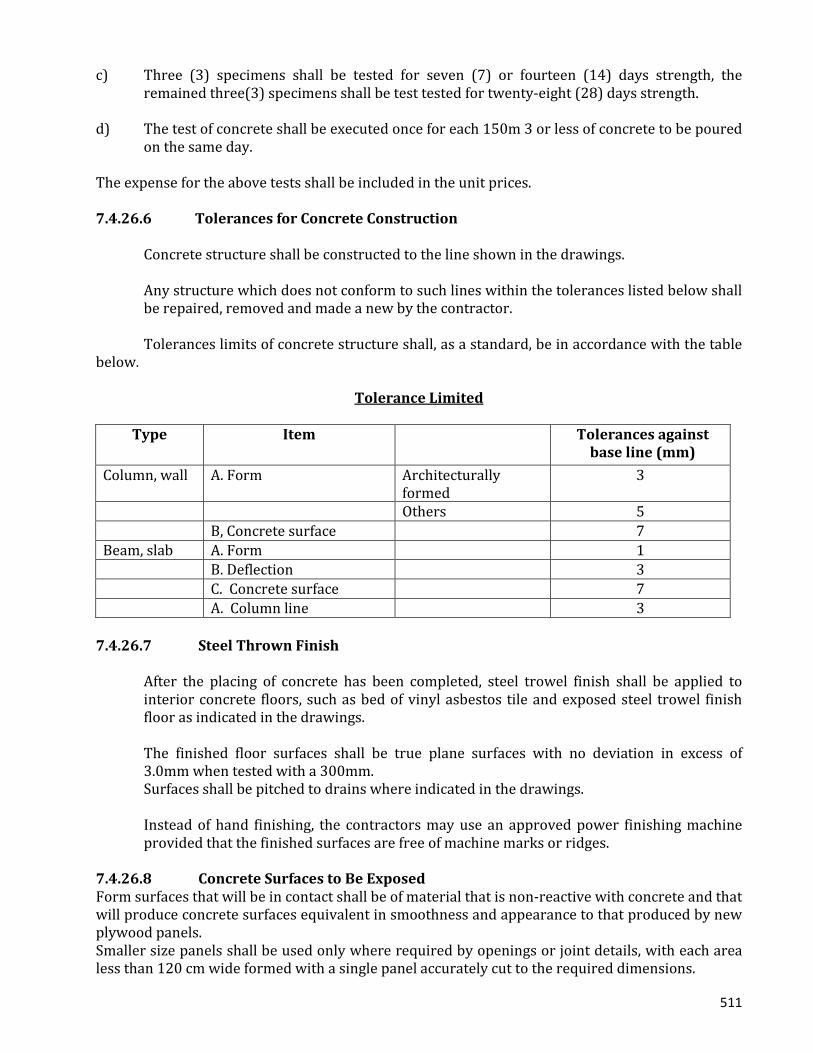
511
c) Three (3) specimens shall be tested for seven (7) or fourteen (14) days strength, the
remained three(3) specimens shall be test tested for twenty-eight (28) days strength. d) The test of concrete shall be executed once for each 150m 3 or less of concrete to be poured
on the same day. The expense for the above tests shall be included in the unit prices. 7.4.26.6 Tolerances for Concrete Construction Concrete structure shall be constructed to the line shown in the drawings.
Any structure which does not conform to such lines within the tolerances listed below shall be repaired, removed and made a new by the contractor.
Tolerances limits of concrete structure shall, as a standard, be in accordance with the table below.
Tolerance Limited
Type Item Tolerances against base line (mm)
Column, wall A. Form Architecturally formed
3
Others 5 B, Concrete surface 7 Beam, slab A. Form 1 B. Deflection 3 C. Concrete surface 7 A. Column line 3
7.4.26.7 Steel Thrown Finish
After the placing of concrete has been completed, steel trowel finish shall be applied to interior concrete floors, such as bed of vinyl asbestos tile and exposed steel trowel finish floor as indicated in the drawings.
The finished floor surfaces shall be true plane surfaces with no deviation in excess of 3.0mm when tested with a 300mm.
Surfaces shall be pitched to drains where indicated in the drawings.
Instead of hand finishing, the contractors may use an approved power finishing machine provided that the finished surfaces are free of machine marks or ridges.
7.4.26.8 Concrete Surfaces to Be Exposed Form surfaces that will be in contact shall be of material that is non-reactive with concrete and that will produce concrete surfaces equivalent in smoothness and appearance to that produced by new plywood panels. Smaller size panels shall be used only where required by openings or joint details, with each area less than 120 cm wide formed with a single panel accurately cut to the required dimensions.
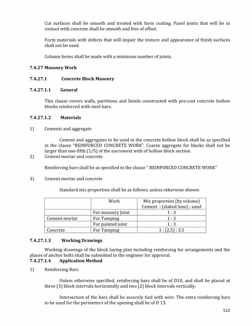
512
Cut surfaces shall be smooth and treated with form coating. Panel joints that will be in contact with concrete shall be smooth and free of offset.
Form materials with defects that will impair the texture and appearance of finish surfaces shall not be used.
Column forms shall be made with a minimum number of joints. 7.4.27 Masonry Work 7.4.27.1 Concrete Block Masonry 7.4.27.1.1 General
This clause covers walls, partitions and lintels constructed with pre-cast concrete hollow blocks reinforced with steel bars.
7.4.27.1.2 Materials 1) Cements and aggregate Cement and aggregates to be used in the concrete hollow block shall be as specified
in the clause “REINFORCED CONCRETE WORK”. Coarse aggregate for blocks shall not be larger than one-fifth (1/5) of the narrowest with of hollow block section.
2) Cement mortar and concrete Reinforcing bars shall be as specified in the clause “ REINFORCED CONCRETE WORK” 3) Cement mortar and concrete Standard mix proportion shall be as follows, unless otherwise shown:
Work Mix proportion (by volume) Cement : (slaked lime) : sand
For masonry Joint 1 : 3 Cement mortar For Tamping 1 : 3 For painted joint 1 : 3 Concrete For Tamping 1 : (2.5) : 3.5
7.4.27.1.3 Working Drawings Working drawings of the block laying plan including reinforcing for arrangements and the places of anchor bolts shall be submitted to the engineer for approval. 7.4.27.1.4 Application Method
1) Reinforcing Bars Unless otherwise specified, reinforcing bars shall be of D10, and shall be placed at
three (3) block intervals horizontally and two (2) block intervals vertically. Intersection of the bars shall be securely tied with wire. The extra reinforcing bars
to be used for the perimeters of the opening shall be of D 13.
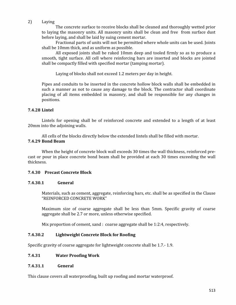
513
2) Laying The concrete surface to receive blocks shall be cleaned and thoroughly wetted prior
to laying the masonry units. All masonry units shall be clean and free from surface dust before laying, and shall be laid by suing cement mortar.
Fractional parts of units will not be permitted where whole units can be used. Joints shall be 10mm thick, and as uniform as possible.
All exposed joints shall be raked 10mm deep and tooled firmly so as to produce a smooth, tight surface. All cell where reinforcing bars are inserted and blocks are jointed shall be compactly filled with specified mortar (tamping mortar).
Laying of blocks shall not exceed 1.2 meters per day in height. Pipes and conduits to be inserted in the concrete hollow block walls shall be embedded in
such a manner as not to cause any damage to the block. The contractor shall coordinate placing of all items embedded in masonry, and shall be responsible for any changes in positions.
7.4.28 Lintel Lintels for opening shall be of reinforced concrete and extended to a length of at least 20mm into the adjoining walls. All cells of the blocks directly below the extended lintels shall be filled with mortar. 7.4.29 Bond Beam When the height of concrete block wall exceeds 30 times the wall thickness, reinforced pre-cast or pour in place concrete bond beam shall be provided at each 30 times exceeding the wall thickness. 7.4.30 Precast Concrete Block 7.4.30.1 General
Materials, such as cement, aggregate, reinforcing bars, etc. shall be as specified in the Clause “REINFORCED CONCRETE WORK”
Maximum size of coarse aggregate shall be less than 5mm. Specific gravity of coarse aggregate shall be 2.7 or more, unless otherwise specified.
Mix proportion of cement, sand : coarse aggregate shall be 1:2:4, respectively. 7.4.30.2 Lightweight Concrete Block for Roofing Specific gravity of coarse aggregate for lightweight concrete shall be 1.7.- 1.9. 7.4.31 Water Proofing Work 7.4.31.1 General This clause covers all waterproofing, built up roofing and mortar waterproof.
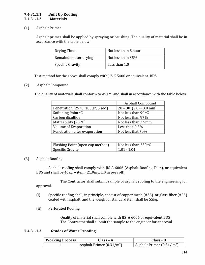
514
7.4.31.1.1 Built Up Roofing 7.4.31.1.2 Materials (1) Asphalt Primer Asphalt primer shall be applied by spraying or brushing. The quality of material shall be in
accordance with the table below:
Drying Time Not less than 8 hours
Remainder after drying Not less than 35%
Specific Gravity Less than 1.0
Test method for the above shall comply with JIS K 5400 or equivalent BDS (2) Asphalt Compound The quality of materials shall conform to ASTM, and shall in accordance with the table below.
Asphalt Compound Penetration (25 oC, 100 gr, 5 sec.) 20 – 30 (2.0 ~ 3.0 mm) Softening Point oC Not less than 90 oC Carbon disulfide Not less than 97% Matteability (25 oC) Not less than 2.5mm Volume of Evaporation Less than 0.5% Penetration after evaporation Not less that 70%
Flashing Point (open cup method) Not less than 230 oC Specific Gravity 1.01 - 1.04
(3) Asphalt Roofing
Asphalt roofing shall comply with JIS A 6006 (Asphalt Roofing Felts), or equivalent BDS and shall be 45kg. – item (21.0m x 1.0 m per roll) The Contractor shall submit sample of asphalt roofing to the engineering for approval. (i) Specific roofing shall, in principle, consist of copper mesh (#38) or glass-fiber (#23)
coated with asphalt, and the weight of standard item shall be 55kg. (ii) Perforated Roofing Quality of material shall comply with JIS A 6006 or equivalent BDS The Contractor shall submit the sample to the engineer for approval.
7.4.31.1.3 Grades of Water Proofing
Working Process Class – A Class - B 1 Asphalt Primer (0.31/m2) Asphalt Primer (0.31/ m2)

515
2 Perforated roofing within layer of sand
Asphalt (0.1 kg/ m2)
3 Asphalt (1.2 kg/ m2) Asphalt Roofing 4 Special roofing Asphalt (1.0 kg/ m2) 5 Asphalt (1.0 kg/ m2) Special roofing 6 Special roofing Asphalt (1.0 kg/ m2) 7 Asphalt (1.0 kg/ m2) Asphalt roofing 8 Asphalt roofing 9 Asphalt (2.0 kg/ m2)
Class – A shall be applied for the roof. Class – B shall be applied for the lavatory. Inclination of the base concrete shall be, in principle, more than 1/100. 7.4.31.1.4 Application Method
Asphalt primer shall be evenly sprayed over the base concrete or roof insulation board. Asphalt compound shall then be vinyl poured and spread over the asphalt primer. Compound heated to a temperature exceeding 230oC shall not be used.
In the case of class – A, perforated roofing shall be laid between asphalt primer and asphalt compound.
Asphalt felt, roofing and special roofing shall be flatly laid over each respective asphalt compound. The sides and ends of these sheets shall be provided with an overlap of at least 9 centimeters. The joints shall be completely water tight and not be concentrated.
Care shall be exercised for the roofing works surrounding anchor bolts, parapets and roof drains to prevent any leakage.
7.4.32 Mortar Waterproofing The waterproofing agent shall be used for mortar waterproofing of roof and balcony.
Cement and sand to be used for waterproofing mortar shall be as specified in the clause “PLASTER WORK”
The catalogue and mix proportion shall be submitted to the Engineer for approval. The application method of mortar shall be as specified in the clause “PLASTER WORK” 7.4.32.1 Caulking 7.4.32.2 General
The Contractor shall furnish all materials, labor and equipment necessary to complete the work as specified or as directed by the engineer.
The contractor shall submit the catalogues and work procedures to the engineer for approval.
516
7.4.32.3 Material
(1) Oil caulking compound shall conform to JIS A 5751 (Oil Based Caulking compounds Buildings ) or equivalent.
(2) Thiokol caulking shall conform to JIS A 5754 (Polysulfide Sealing compound for Buildings)
or equivalent. (3) Thiokol caulking shall be used as joint for all surroundings of exterior doors, windows and
concrete panels. 7.4.32.4 Workmanship
All joint surfaces to be filled shall be sound, clean and dry. All concrete surfaces shall be fully cured before application of caulking.
Joint surfaces to be filled shall be primed with the manufacturer’s recommended primer, compatible with the Thiokol base sealing compound and appropriate for the surfaces to be sealed.
Mixing and application of filling compound shall be in accordance with the manufacturer’s recommendations, and shall be submitted to the engineer for approval.
All filler work shall be done by skilled workmen. 7.4.33 Control Joint For Roof
Control joint shall be provided between mortar finish and light weight concrete block and at about 4.0mm of intervals in light weight concrete block area of roof.
Control joint shall consists of elastight and asphalt mortar. 7.4.34 Tile Work 7.4.34.1 General This clause covers all works required for mosaic tile, ceramic tile and others applied on floors and wall. Working drawings shall be submitted to the engineer for approval. Prior to starting work, the contractor shall submit samples of tile to the Engineer for approvals. 7.4.34.2 Materials 7.4.34.2.1 Floor Finish ● To be used 900mmx900mm (36 inch x 36inch) size European standard Mirror Polished Homogeneous tiles for 1st to 6th Floor.
517
● For Ground/Underground Floor finish to be used as per Transformer based design such as use dry gravels for bottom of the Transformer and Rustic Tiles for walk way or common space.
Materials to be used in the works shall be high quality, high grade and good appearance.
7.4.34.2.2 Ceramic Tile for Interior Wall Finish (GWI) for Bath room’s wall Special color and size of European standard Ceramic Tile with decorative Boarder shall be used in Bath rooms & other necessary interior walls. Materials to be used in the work shall be high quality, high grade and good appearance. 7.4.34.2.3 Ceramic Tile for Exterior Wall Finish
Ceramic tile for exterior wall finish shall be of 60mm x 227mm, colored, glazed and manufactured by qualified manufacturer as approved by the engineer. (if required)
The color of tile shall be designated by the engineer. 7.4.34.2.4 Setting Materials
(1) Cement, sand to be used for mortar bed shall be as specified in the clause “REINFORCED CONCRETE WORK”
(2) Bedding mortar shall be mixed with one part Portland Cement and three parts sand.
7.4.34.3 Setting (1) Mosaic Tile The mortar setting bed shall be floated to a uniform plumb and level surface to bring the
finish surface to the required plane. Thickness of mortar shall be about 10 millimeters. Mosaic sheets shall be placed in positions on the pure coat and freshly combed into the
mortar setting bed with trowel. Sheets shall be tamped firmly into place and made true and even with the finished surface line or plane.
Expansion joints or control joints at 6 meters on center shall continue through the mortar
bed and mosaic tile and shall be kept free from mortar and grout. Those shall be filled with an approved caulking compound and shall be as close as possible to the color of the grout mortar. All joints, after removal of the paper, shall be grouted leaving then completely and uniformly filled. At no time shall sand or any abrasive be used that will damage the natural sheen of the mosaic tile. All excess grout and glue shall be removed from the face of the tile leaving the finished surface clean.
518
(2) Ceramic Tile Laying of ceramic tile shall comply with the specifications for “ Mosaic Tile” for floors, tile
lay out work shall begin from the center lines of areas to eliminate use of half tiles. For walls, tile layout work shall begin from the top of the wall and proceed downward. Tile shall be soaked in clean water for at least one hour prior to setting and applied to
setting beds within five minutes after soaking. (3) Protection The contractor shall provide and install barriers or other forms of protection and covering
to prevent damages. (4) Cleaning Tiles shall be thoroughly cleaned after grouting and painting has sufficiently set. A;; traces
of cement or foreign matter shall be removed from tiles. Exposed hardware and plumbing trim shall be covered with baseline during tile setting. Base line shall be removed and metal shall be cleaned and polished.
7.4.34.4 Gun Sprayed Tile Gun sprayed tile shall be applied on the surface of concrete as indicated in the drawings. Gun sprayed tile shall conform to JIS A 6910 - C or equivalent. Sealer shall be applied on the concrete surface so as to prevent moisture from main material and to increase adhesion of main material. Main material shall consist of white Portland Cement, dolomite plaster and coloring agent. The color shall be designated by the Engineer. 7.4.35 Metal Works 7.4.35.1 General This clause covers all metal works for flooring, siding, walling, flushing, railings, roofing, raiser, plumbing, and other pertinent fixtures. The contractor shall submit fabrication and installation drawings to the engineer for approval.
519
7.4.35.2 Handrails 7.4.35.2.1 Steel Railings For Stair case railing to be used Stainless Steel Pipe, Square Box & other decorative post as per drawing to the engineer for approval. Steel railings, including pipe inserts to be embedded in concrete shall conform to JIS G 3452 and shall be galvanized, unless otherwise specified. Square pipe shall be of the size indicated in the Drawings. Galvanizing coat damaged by bolting, welding and other field works shall be repaired and painted with two coats of silver zinc paint. 7.4.35.2.2 Fabrication
Mitered and welded joints shall be made by fitting post to top rail and intermediate rail to post mitering comers, groove welding joints, and grinding smooth. Railings may be bent at comers instead of jointed, provided that the bends are made in suitable jigs and that the pipe is not crushed or damage.
Edge of the railings shall be covered with steel plates. 7.4.35.2.3 Installation
Rails shall be installed by means of steel sleeve inserts which shall be seat and anchored in the concrete.
Ports shall be inserted into the galvanized steel sleeves embedded in concrete or shall be welded to the stringer, beam or toe plate made level, perpendicular and aligned.
The space between pipe posts and pips sleeve inserts except those marked “ Removable handrail” as indicated in the drawings shall be filled solid with molten lead or shall be welded.
7.4.35.3 Steel Ladders Materials to be used for steel ladders shall conform to JIS G 3101 – SS 41 or equivalent.
Steel ladders shall be fabricated of l- 65 x 6 steel angle stringers and 19mm diameter steel bar rungs. Rungs shall be spaced 350mm apart and shall be inserted into the stringers and welded thereto.
The ladders, including welded on bracket, shall be pointed.
520
7.4.35.4 Corner Guards
Comer guards for jamps, where directed by the engineer and sills of opening and edges of concrete column and wall shall be of steel angles or steel plates, conforming to JIS G 3101-SS 41 or equivalent, anchored into concrete with welded steel straps or end weld stud anchors.
7.4.35.5 Stair Safety Nosing for Concrete Stair Stair safety nosing shall be of extruded bronze or stainless steel with cross hatched nosing. Safety nosing shall be provided with integrally cast or bent anchors for embedding into concrete. 7.4.35.6 Divider Strips
Divider strips shall be half hard brass and shall be placed between different types of floorings as indicated. Divider strips shall be secured to floors by strip anchors or by flat head countersunk brass screws set in lead plugs.
7.4.35.7 Roof Drain
Roof drains shall be of cast iron baked with refined tar and shall conform to JIS A 5511, or equivalent, The size shall be in accordance with the drawings.
7.4.35.8 Corner Bead
Corner bead shall be half hard brass, and shall be placed at edges of columns and wall where mortar or plaster is applied.
7.4.35.9 Blind Box
Blind boxes shall be provided above all windows faced to outdoor, excepting for lavatory, storage, janitorial, kitchen and rooms which located on the first floor.
They shall be constructed of 1.6mm thick steel plate conforming to JIS G 3131, JIS G 3141 or equivalent and shall be painted.
Hanger bracket for installation of the blind box shall be galvanized 6mm thickness flat bar conforming to JIS G 3101 SS 41 and shall be installed at spacing of 90cm diameter expansion blots.
Connection between blind box and hanger bracket shall be 6mm diameter bolts and nuts. 7.4.35.10 Door sill Prior to commencement of floor finish work, door sill shall be provided in place between different types of flooring, unless other wise indicated, and shall be stainless steel conforming to JIS G 4305 – SUS 304 or equivalent. 7.4.35.11 Flashing Plate
Flashing Plates shall be of 2.3mm galvanized steel plate conforming to JIS G 3131, G 2341 or equivalent.
521
Flashing plates shall be provided at wall and roof opening for piping and at surrounding areas of windows, louvers rolling doors and doors facing outdoors. 7.4.35.1 2 Embedded Plate, Hook and Sleeve The contractor shall provide plates, hooks and sleeves to be embedded in concrete as required.
Embedded plates, hooks and sleeves shall have sufficient thickness, diameter and anchorage in order to fix equipment, piping and other necessary items. Painting shall be applied on the plates and hooks after fixing the equipment and piping.
The materials to be used for plates, hooks and sleeves shall conform to JIS G 3101 SS 41 or equivalent.
7.4.35.13 Joiner
Joiners shall be provided at surrounding space of suspended ceilings and shall be of aluminum conforming to JIS H 4000 or equivalent.
Small screws shall be of stainless steel or of high strength aluminum alloy. 7.4.35.14 Down Spout Downspouts to be used for drains shall be steel pipe conforming to JIS G 3442 or equivalent. Metal bracket shall be of 50mm x 4.5mm steel plate conforming to JIS G 3101 SS 41 or equivalent and galvanized. Downspouts shall be fixed with metal brackets at maximum of 2.0m per space. 7.4.36 Plaster Work 7.4.36.1 General 7.4.36.1.1 Treatment of Bed (1) Concrete surfaces which are too smooth to receive plastering shall be roughened before
hand with chisels. (2) Where wall and floors of concrete, concrete block, etc. are distorted or uneven, the bed shall
be repaired with mortar. 7.4.36.1.2 Cleaning and Wetting of Bed The bed, scratch coat, and treated surface of bed shall be cleaned and suitably wetted before application of the following coat. Portions of the base or coated surface which are not bonded shall be immediately repaired.
522
7.4.36.1.3 Curing In order to prevent soiling and premature drying of plastered surface, window and door work shall be completed prior to commencement of the plaster work sheet coverings provided and sprinkling of water performed. In order to prevent the soiling of neighboring members and other finished surface, suitable protection shall be provided using paper, boarding, tarpauling sheet or other suitable means. 7.4.37 Mortar Plastering 7.4.37.1 Materials (1) Cement shall conform to JIS R 5210 ordinary Portland Cement or locally produced
equivalent. (2) Sand shall be of good quality free of salts, mud, trash and /or organic matters. The
gradation shall be in accordance with the table below.
Table Gradation of Sand Gradation (by weight) Type of Mortar Plastering Passing 5mm sieve…………..100% First coat ad second coat Passing 0.15mm sieve ………not more than 10% Passing 2.5mm sieve…………100% Finish coat Passing 0.15mm sieve………..not more than 10% Water shall be clean and free of sales, iron, sulfur and/ or organic matter, as specified in he clause “ CONCRETE WORK”. 7.4.37.2 Mixing The mix proportions of mortar shall be of standard type in accordance with the table below.
Table Mix Proportion (by Volume)
Base Portion to be Plastered First Coat
Second Coat Finish Coat
C : S C : S C : S Slaked Lime Floor 1 : 2 Interior Wall 1 : 2 1 : 3 1 : 3 : 0.3 Concrete Ceiling 1 : 2 1 : 3 : 0.3
Concrete Block Exterior Wall and others 1 : 2 1 : 3 1 : 3 Wire lath Interior Wall 1 : 3 1 : 3 1 : 3 : 0.3 Metal Lath Ceiling 1 : 2 1 : 3 1 : 3 : 0.3 Exterior wall and others 1 : 3 1 : 3 1 : 3
In the above table, abbreviated C and S mean cement and sand, respectively. 7.4.37.3 Plastering Thickness

523
The thickness of application shall be in accordance with the standards indicated in the table below.
Table Plastering Thickness
Plastering Thickness (mm) Bed Portion to be
plastered First coat Dubbing
Coat Second
Coat Finish Coat Total
Floor - - - 30 30 Concrete Interior wall 6 5 6 3 20 Concrete Block Exterior wall 6 7 6 6 25 Ceiling, others 4.5 - 4.5 3 12 Interior wall 7.4 - 7.4 3 18 Wire Lath Exterior wall 6 - 7.4 3 18 Metal Lath Ceiling, waves 4.5 - 4.5 3 12
7.4.37.4 Application Method (1) First Coat and Dubbing Out Mortar shall be trawled on adequately to leave on conspicuous hollow. The surface of the first coat shall be roughened with tools such as metal combs. The first coat shall be left standing for not less then 10 days allowing cracks to be fully developed before applying the next coat. Dubbing out for concrete and concrete block shall be performed by roughening with tools such as metal combs and shall be left standing for not less then 5 days. (2) Second Coat For the second coat, a ruler shall be provided at external corners, internal corners and edges applied on order to attain an even finish. (3) Finish Coat The finish coat shall be applied in a manner so as to be blemish free by watching the degree of drying of the brown coat and by paying special attention to the surface, angles and edges. The finish shall be either steel toweled, wood troweled or brushed as directed by the engineer. For the exterior wall, the mortar shall first be troweled on with a wood travel, then furnished with a steel trowel and finally brushed avoiding use of water as much as possible. (4) Floor Mortaring In the case of concrete which is several days old, concrete paste shall be buttered on in adequate quantity and spread out with brooms and the like after which application of mortar shall be started.
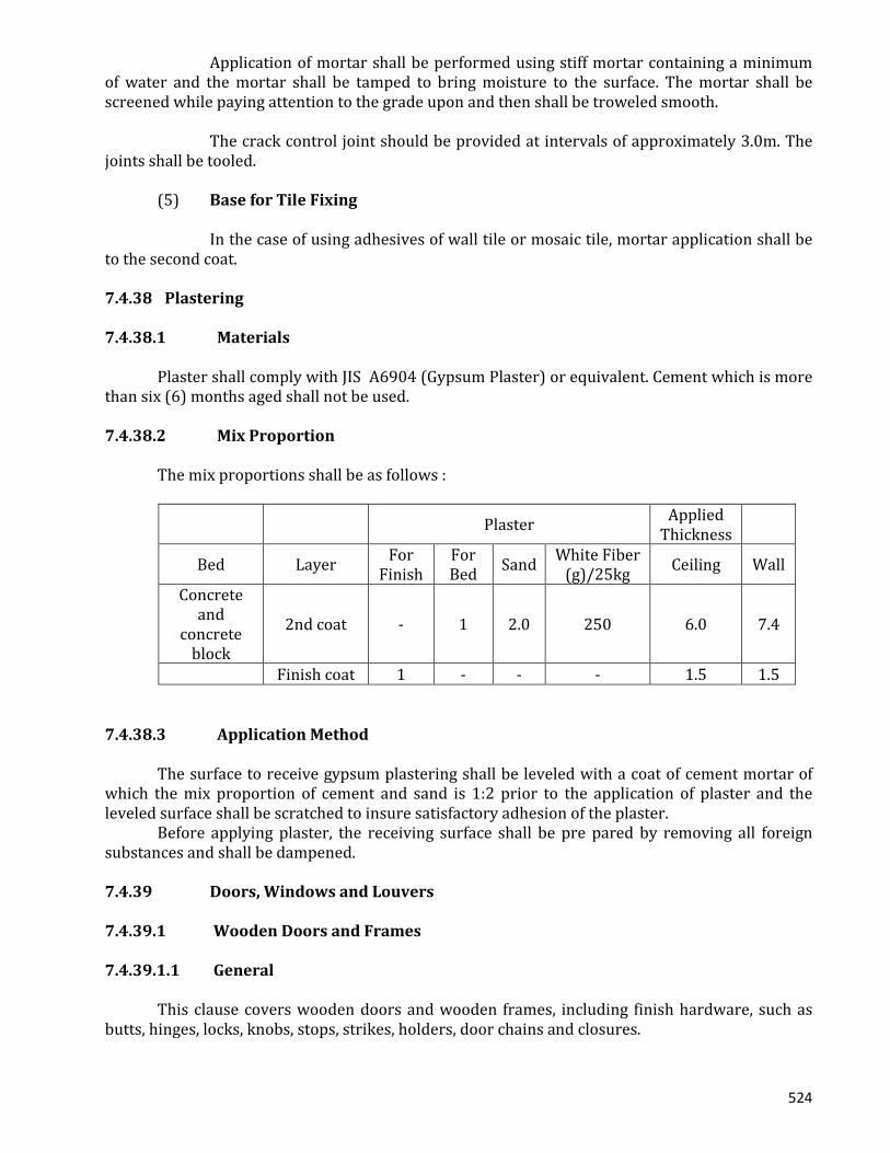
524
Application of mortar shall be performed using stiff mortar containing a minimum of water and the mortar shall be tamped to bring moisture to the surface. The mortar shall be screened while paying attention to the grade upon and then shall be troweled smooth. The crack control joint should be provided at intervals of approximately 3.0m. The joints shall be tooled. (5) Base for Tile Fixing In the case of using adhesives of wall tile or mosaic tile, mortar application shall be to the second coat. 7.4.38 Plastering 7.4.38.1 Materials Plaster shall comply with JIS A6904 (Gypsum Plaster) or equivalent. Cement which is more than six (6) months aged shall not be used. 7.4.38.2 Mix Proportion The mix proportions shall be as follows :
Plaster Applied Thickness
Bed Layer For Finish
For Bed Sand White Fiber
(g)/25kg Ceiling Wall
Concrete and
concrete block
2nd coat - 1 2.0 250 6.0 7.4
Finish coat 1 - - - 1.5 1.5 7.4.38.3 Application Method The surface to receive gypsum plastering shall be leveled with a coat of cement mortar of which the mix proportion of cement and sand is 1:2 prior to the application of plaster and the leveled surface shall be scratched to insure satisfactory adhesion of the plaster. Before applying plaster, the receiving surface shall be pre pared by removing all foreign substances and shall be dampened. 7.4.39 Doors, Windows and Louvers 7.4.39.1 Wooden Doors and Frames 7.4.39.1.1 General This clause covers wooden doors and wooden frames, including finish hardware, such as butts, hinges, locks, knobs, stops, strikes, holders, door chains and closures.

525
7.4.39.1.2 Materials All doors shall be flush type, of sizes as shown in the drawings. Materials shall be, in principle, locally principle, locally produced. Standard flush doors be double paneled door of 6mm thick plywood and shall have stiffening ribs spaced at intervals of 15cm. Plywood shall be bended to the frames with a suitable adhesives which shall conform JIS K 6801 and 6803 or equivalent. Waterproofed plywood shall be used for wooden doors for the lavatory. The waterproofed plywood shall be of 6mm thickness five (5) play and the weight shall be 4.79 kg/m2. The each layer shall be completely pressed and adhered by using phonetic resin adhesives and the plywood shall be passed a boiling test and a dry and wet repeating test. All wooden doors and frames shall be painted as specified in clause “PAINTING” unless otherwise specified. 7.4.39.1.3 Shop Drawings The contractor shall submit stop drawings of fabricated items to the engineer for approval. The shop drawings shall clearly show the details of fabrication, installation, sizes, operation, methods of anchoring and any other pertinent details required for the installation thereof. 7.4.39.1.4 Wooden Door Frames All frames shall be accurately set, plumb, level and shall be securely nailed to the wooden blocks embedded in the concrete or mortar. Door Frame and Shutter should be made by solid wood such as Burma Teak as per direction/decision of the employer
7.4.39.1.5 Installation Each door shall be accurately cut, trimmed and fitted to its frame and hardware with allowance for paint finish and possible swelling or shrinkage. The clearance at the top shall not exceed 6mm. 7.4.39.1.6 Hardware for Wooden Doors Hardware for wooden doors shall in principle be stainless steel conforming to The
applicable standards are listed below :
BDS 113:1986 Specification for Latches and Locks for Doors in Buildings;
IS 204-78 Specification for Tower Bolts;
Part I Ferrous Metals (Fourth Revision);
Part II Nonferrous metals (Fourth Revision);
IS 205-1978 Specification for Nonferrous Metal Butt Hinges (Third Revision);
IS 206-1981 Specification for Tee and Strap Hinges (Third Revision);
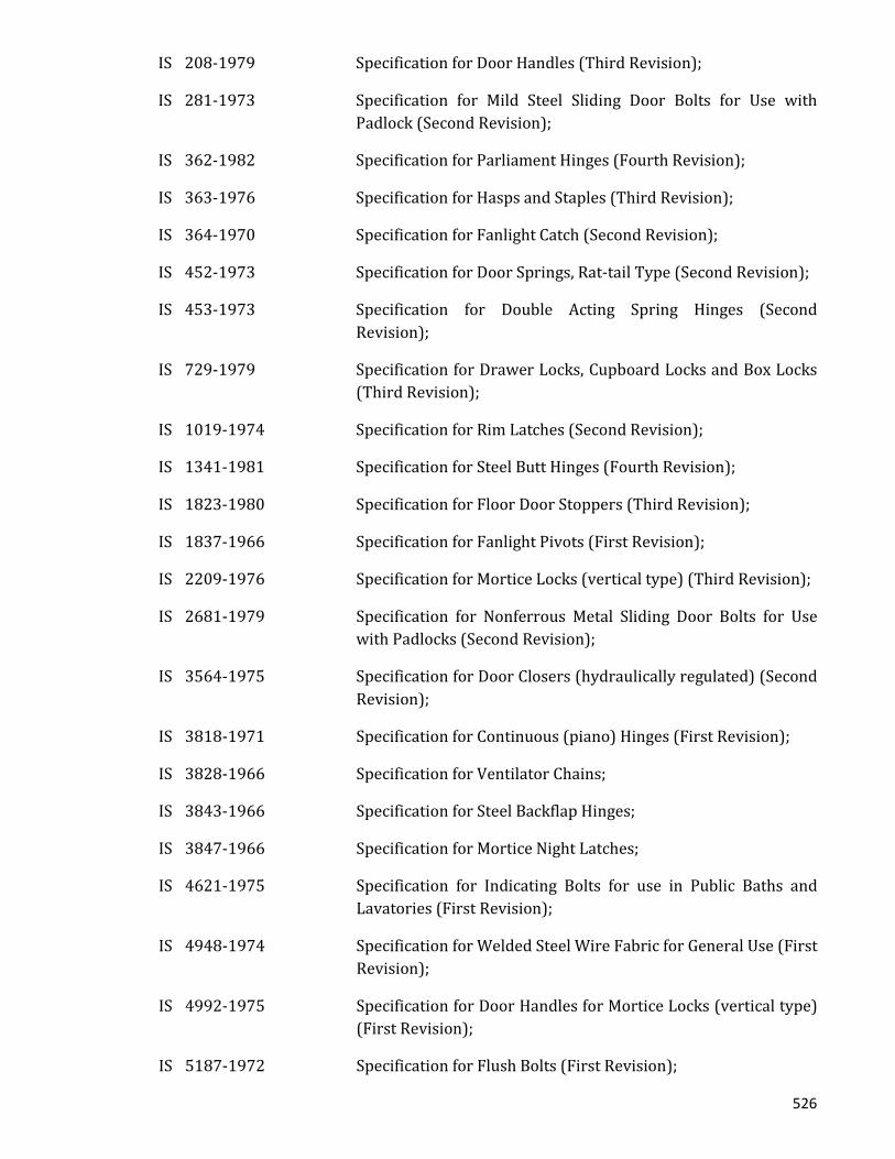
526
IS 208-1979 Specification for Door Handles (Third Revision);
IS 281-1973 Specification for Mild Steel Sliding Door Bolts for Use with Padlock (Second Revision);
IS 362-1982 Specification for Parliament Hinges (Fourth Revision);
IS 363-1976 Specification for Hasps and Staples (Third Revision);
IS 364-1970 Specification for Fanlight Catch (Second Revision);
IS 452-1973 Specification for Door Springs, Rat-tail Type (Second Revision);
IS 453-1973 Specification for Double Acting Spring Hinges (Second Revision);
IS 729-1979 Specification for Drawer Locks, Cupboard Locks and Box Locks (Third Revision);
IS 1019-1974 Specification for Rim Latches (Second Revision);
IS 1341-1981 Specification for Steel Butt Hinges (Fourth Revision);
IS 1823-1980 Specification for Floor Door Stoppers (Third Revision);
IS 1837-1966 Specification for Fanlight Pivots (First Revision);
IS 2209-1976 Specification for Mortice Locks (vertical type) (Third Revision);
IS 2681-1979 Specification for Nonferrous Metal Sliding Door Bolts for Use with Padlocks (Second Revision);
IS 3564-1975 Specification for Door Closers (hydraulically regulated) (Second Revision);
IS 3818-1971 Specification for Continuous (piano) Hinges (First Revision);
IS 3828-1966 Specification for Ventilator Chains;
IS 3843-1966 Specification for Steel Backflap Hinges;
IS 3847-1966 Specification for Mortice Night Latches;
IS 4621-1975 Specification for Indicating Bolts for use in Public Baths and Lavatories (First Revision);
IS 4948-1974 Specification for Welded Steel Wire Fabric for General Use (First Revision);
IS 4992-1975 Specification for Door Handles for Mortice Locks (vertical type) (First Revision);
IS 5187-1972 Specification for Flush Bolts (First Revision);

527
IS 5899-1970 Specification for Bathroom Latches;
IS 5930-1970 Specification for Mortice Latch (vertical type);
IS 6315-1971 Specification for Floor Springs (hydraulically regulated) for Heavy Doors;
IS 6318-1971 Specification for Plastic Window Stays and Fasteners;
IS 6343-1982 Specification for Door Closers (pneumatically regulated) for Light Doors Weighing up to 40 kg (First Revision);
IS 6602-1972 Specification for Ventilator Poles;
IS 6607-1972 Specification for Rebated Mortice Locks (vertical type);
IS 7196-1974 Specification for Hold Fast;
IS 7197-1974 Specification for Double Action Floor Springs (without oil check) for Heavy Doors;
IS 7534-1974 Specification for Mild Steel Locking Bolts with Holes for Padlocks;
IS 7540-1974 Specification for Mortice Dead Locks;
IS 8756-1978 Specification for Ball Catches for use in Wooden Almirah;
IS 8760-1978 Specification for Mortice Sliding Door Locks, with Lever Mechanism;
IS 9106-1979 Specification for Rising Butt Hinges;
IS 9131-1979 Specification for Rim Locks;
IS 9460-1980 Specification Flush Drop Handle for Drawer;
IS 9899-1981 Specification for Hat, Coat and Wardrobe Hooks;
IS 10019-1981 Specification for Steel Window Stays and Fasteners;
IS 10090-1982 Specification for Numericals;
IS 10342-1982 Specification for Curtain Rail System
or equivalent.
7.4.40 Steel Fittings 7.4.40.1 General This clause covers steel fittings, including finish hardware, such as butts, hinges, locks, knobs, stops, strikes, holders, door chains and closures.
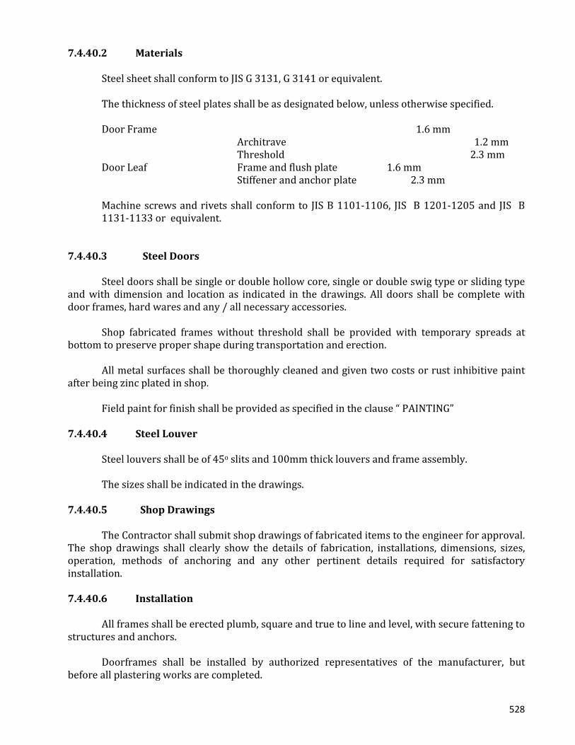
528
7.4.40.2 Materials Steel sheet shall conform to JIS G 3131, G 3141 or equivalent. The thickness of steel plates shall be as designated below, unless otherwise specified. Door Frame 1.6 mm Architrave 1.2 mm Threshold 2.3 mm Door Leaf Frame and flush plate 1.6 mm Stiffener and anchor plate 2.3 mm
Machine screws and rivets shall conform to JIS B 1101-1106, JIS B 1201-1205 and JIS B 1131-1133 or equivalent.
7.4.40.3 Steel Doors Steel doors shall be single or double hollow core, single or double swig type or sliding type and with dimension and location as indicated in the drawings. All doors shall be complete with door frames, hard wares and any / all necessary accessories. Shop fabricated frames without threshold shall be provided with temporary spreads at bottom to preserve proper shape during transportation and erection. All metal surfaces shall be thoroughly cleaned and given two costs or rust inhibitive paint after being zinc plated in shop. Field paint for finish shall be provided as specified in the clause “ PAINTING” 7.4.40.4 Steel Louver Steel louvers shall be of 45o slits and 100mm thick louvers and frame assembly. The sizes shall be indicated in the drawings. 7.4.40.5 Shop Drawings The Contractor shall submit shop drawings of fabricated items to the engineer for approval. The shop drawings shall clearly show the details of fabrication, installations, dimensions, sizes, operation, methods of anchoring and any other pertinent details required for satisfactory installation. 7.4.40.6 Installation All frames shall be erected plumb, square and true to line and level, with secure fattening to structures and anchors. Doorframes shall be installed by authorized representatives of the manufacturer, but before all plastering works are completed.

529
7.4.41 Aluminum Fitting 7.4.41.1 General This clause covers all types of aluminum door, window, casements, and swing, sliding, pivoted, projected, fired and combination doors and windows, including operation hardware. 7.4.41.2 Materials Extruded aluminum shape and sheet shall conform to JIS H 4100 and H 4000 respectively or equivalent. Reinforcing strips, reinforcing struts anchors, etc. shall be of zinc plated steel plate conform G 310-SS41. Small screws shall be of stainless steel conforming to JIS G 5121 SUS 304or of high strength aluminum alloy conforming to JIS H 4040 or equivalent. 7.4.41.3 Shop Drawings The Contractor shall submit shop drawings of fabricated items to the engineer for approval. The shop drawings shall clearly show the details of fabrication, installation, dimensions, sizes, operation, methods of anchoring and any other pertinent details required for satisfactory installation. 7.4.41.4 Installation All aluminum windows shall be installed by the manufacturer or his authorized representative and shall be set plumb, square, level and true to line. Frames shall be set and securely anchored to the structure. Aluminum surface in contact or other masonry materials shall be provided one heavy brush coat of bituminous paint. Upon completion of the work the contractor shall remove and clean all surplus materials from these areas. 7.4.42 Glass And Glazing 7.4.42.1 General
The contractor shall furnish and install all glass required in doors and windows in accordance with the drawings and any direction of the engineer. The applicable standards for glass and glazing are listed below :
ASTM C1036-90 Specification for Flat Glass;
ASTM C1044-90 Specification of Heat-Treated Flast Glass Kind HS, Kind FT Coated and Uncoated Glass;
ANSI Z 97.1 Safety Performance Specifications and Methods of Tests for Transport Safety Glazing Materials Used in Building;
CPSC 16 CFR Safety Standard for Architectural Glazing Materials.
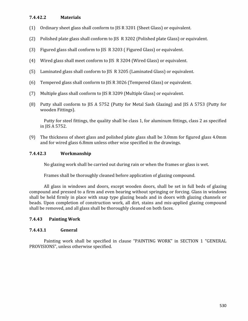
530
7.4.42.2 Materials
(1) Ordinary sheet glass shall conform to JIS R 3201 (Sheet Glass) or equivalent. (2) Polished plate glass shall conform to JIS R 3202 (Polished plate Glass) or equivalent. (3) Figured glass shall conform to JIS R 3203 ( Figured Glass) or equivalent. (4) Wired glass shall meet conform to JIS R 3204 (Wired Glass) or equivalent. (5) Laminated glass shall conform to JIS R 3205 (Laminated Glass) or equivalent. (6) Tempered glass shall conform to JIS R 3026 (Tempered Glass) or equivalent. (7) Multiple glass shall conform to JIS R 3209 (Multiple Glass) or equivalent. (8) Putty shall conform to JIS A 5752 (Putty for Metal Sash Glazing) and JIS A 5753 (Putty for
wooden Fittings). Putty for steel fittings, the quality shall be class 1, for aluminum fittings, class 2 as specified
in JIS A 5752. (9) The thickness of sheet glass and polished plate glass shall be 3.0mm for figured glass 4.0mm
and for wired glass 6.8mm unless other wise specified in the drawings. 7.4.42.3 Workmanship No glazing work shall be carried out during rain or when the frames or glass is wet. Frames shall be thoroughly cleaned before application of glazing compound. All glass in windows and doors, except wooden doors, shall be set in full beds of glazing compound and pressed to a firm and even bearing without springing or forcing. Glass in windows shall be held firmly in place with snap type glazing beads and in doors with glazing channels or beads. Upon completion of construction work, all dirt, stains and mis-applied glazing compound shall be removed, and all glass shall be thoroughly cleaned on both faces. 7.4.43 Painting Work 7.4.43.1 General Painting work shall be specified in clause “PAINTING WORK” in SECTION 1 “GENERAL PROVISIONS”, unless otherwise specified.
531
7.4.44 Interior Finish Work 7.4.44.1 General This clause covers the performance of all works in connection with the following. 1) Vinyl asbestos tile 2) Acid proof vinyl tile 3) Vinyl base 4) Asbestos cement board 5) Acoustic board 6) Suspended ceiling 7) Ceiling Access 8) Insulation 9) Nameplate for rooms 10) Accordion partition 11) Toilet Partition
Prior to starting work, samples of interior finish materials and shop drawings shall be submitted to the engineer for approval.
Types and sizes of nails, screws, bolts and quality of adhesives for fixing of interior finish shall correspond and match to characteristics of the interior finish materials and shall be submitted to the engineer for approval.
7.4.44.2 Fixing Fixing shall not commence until after drying and cleaning of the base. Fixing method of specified materials shall be in accordance with the manufacturer’s specification and shall be submitted to the engineer for approval. In performing fixing, adequate precautions shall be provided to avoid off set, gap and/or unevenness. Suitable protection measures shall be provided on the interior finish until all finishing works are completed. 7.4.44.3 Vinyl Asbestos Tile For Floor Finish
Sizes of vinyl asbestos tile shall be 300mm x 300mm x 3mm thick conforming to JIS A 5705 or equivalent.
- The tiles shall be resistant to alkali, grease or oils. - The vinyl tiles shall be bonded with asphalt adhesives. 7.4.44.4 Acid-Proof Vinyl Tile
The tiles shall be of acid proof type vinyl tile. The shape and dimensions shall be the same as those of vinyl asbestos tile.
532
7.4.44.5 Vinyl Base Vinyl base shall conform to the manufacturer’s recommendation of vinyl asbestos tile for flooring unless otherwise indicated, the height of the base shall be 100mm. 7.4.44.6 Asbestos Cement Board Materials shall conform to “ Flexible Board” in JIS A 5403 (Asbestos Cement Sheets) or equivalent. When necessary, chamfering shall be carried out so as to facilitate the making of joints and prevent their irregularity. Hardware fixings shall be countersunk screws of stainless steel. 7.4.44.7 Acoustic Board For Ceiling (1) The material shall be of incombustible rock wool and perforated . The thickness of board
shall be 12mm. Acoustic boards shall be fixed on the base board with suitable adhesives or nails so
as to facilitate the making of joints and prevent their irregularity. (2) Base Board for Ceiling Base Board shall be plaster boards conforming to JIS A 6901 (Gypsum Board) Grade
2 or equivalent. The thickness of board shall be 9mm. 7.4.44.8 Suspended Ceiling The Contractor shall provide a light weight suspension system. The system shall have the means to properly support the entire ceiling when it is in place. 7.4.44.8.1 Main Runner
Main runners for all suspension system, unless otherwise specified, shall be of cold rolled zinc bonded light channel steel (-38mm x 15mm x 1.6mm) conforming to JIS G 3350.
The channel runner shall be installed 90cm on centers and suspended by steel bars of 6mm dia. Hangers with level adjustable nuts at 90cm intervals.
The grid shall be leveled to within 1/500. 7.4.44.8.2 Cross Furring Cross furring for ceiling shall be of cold rolled zinc bonded steel (M-23-mm x23mm).
533
The M-furring shall be installed 30cm on centers and at right angles to the main runner by wire clips. All M-furring shall be straight in alignment and hold so as to enable level placement of plaster board on the suspension system.
7.4.44.8.3 Workmanship
The installation and workmanship shall be in strict accordance with the manufacturer’s specifications and shall be made by skilled workmen.
7.4.44.8.4 Insulation The contractor shall provide insulation boards under the roof slab.
The insulation boards shall be of 25mm thickness cemented excelsior boards conforming to JIS A 5404 or equivalent.
The insulation boards shall be fixed to forms of slab concrete by using nail. 7.4.44.9 Ceiling Access
Ceiling accesses shall be located at suitable places for maintenance of the lighting system and air conditioning ducts and shall be the size of 600m x 600mm.
The materials of the frame for reinforcement of access board shall be made of the same materials as the ceiling, shall be of aluminum conforming to JIS G 4100.
7.4.44.10 Nameplate For Rooms
Name plates shall be provided on all doors of rooms facing out doors, corridors and other rooms.
The size, materials and name on the plates shall be designated by the engineer. 7.4.44.11 Accordion Partition Accordion partition shall be provided as indicated in the drawings.
Accordion partition shall be of vinyl chloride leather, runner, hinge plate (JIS G 3141 Spec. 1.2mm galvanized), wire rods (JIS G 3505 or equivalent ) hanger rail (JIS H 4100-6063, T5 or equivalent) frames, (HIS H 4100-6063, T5 or equivalent) magnet, cushion rubbers and frame holder weight of partition 1m2 shall be 7 Kg or less.
Panel shall be of plastic laminated board or steel and paper honeycomb.
Doors shall be of the same materials as panels and door frames shall be of Aluminum Alloy Extruded shapes.
7.4.44.12 Toilet Partitions In Case of common toilet:
Melamine coated plywood toilet partitions shall be furnished and installed at the locations indicated in the drawings and as described herein.

534
Toilet partitions shall supported by stainless standing supporters anchored into the floor and y head connection (galvanized square tubing).
Partitions shall be flush type, consisting of two sheets of waterproof plywood. The plywood shall be coated with melamine. All partitions and screen shall be erected plumb, level and in perfect alignment, with hardware fully equipped for proper operation.
7.4.45 Sodding And Planting 7.4.45.1 Sodding 7.4.45.1.1 General
The Contractor shall furnish all work including labor equipment, materials, construction, etc., in connection with sodding work.
7.4.45.1.2 Top Soil with Fertilizer
Stones, leaves, pieces of wood and all foreign matter shall be cleared away before placement of the top soil.
Top soil shall be approved by the engineer. The soil shall be hauled and placed when it is sufficiently dry for spreading.
Manure fertilizer shall be well rotted, unleashed, and free from sawdust, shaving, refuse and / or harmful chemicals.
All manure delivered shall be free from any degree of fly manifestation. All manure fertilizer shall be spread and mixed with the top soil within 48 hours after arrival on the site. Fly breeding prevention shall be by the use of insecticides and / or larvaecides as approved by the engineer.
Areas to be sodded shall be prepared by placing top soil in the areas to the required thickness.
The central part of such areas shall be made higher in comparison to the surroundings to ensure proper drained.
7.4.45.1.3 Sod Planting
Sod planting shall be carried out where indicated in the drawings. Sod shall be planted in firm contact with the bed, and planting work shall be carried out by skilled workmen.
Density of sod planting shall be 70% or more of the area. After fixing the sheets of turf, sandy soil shall be spread at the rate of 0.01-0.02m3 per square meter by using a sieve.
7.4.45.1.4 Leveling of Ground
Before planting the sod, the contractor shall remove all foreign matter, such as weeds, stones and pieces of wood and level the ground. The cost of the leveling of the ground shall be included in the price of the grass planting.
535
7.4.45.1.5 Watering Watering equipment of the type which prevents damage to finished surfaces shall be used. Should the sod become dry, it shall be watered so as to wet the transplanted sod through to t he bottom and through to at least 5cm of the sod bed as well. Additional watering shall be made as directed by the engineer. 7.4.45.1.6 Protection
Protection of seeded beds against traffic, human or otherwise, shall be provided by erecting barricades immediately after work is completed and by placing warring signs, markers etc. as directed by the engineer.
7.4.45.1.7 Maintenance Sodden areas shall be maintained (watering, cutting, etc.) by the contractor until taking over. 7.4.45.1.8 Clean Up
After the turning operation has been completed, the surface shall be cleared of all tones larger than 2cm in diameter and of all roots, brush, trash or other matter that may interfere with maintenance operations.
Any paved area over which hauling operation is conducted shall be kept clean and any top soil or other materials which may lie upon the paved surface shall be promptly removed.
7.4.45.2 Planting 7.4.45.2.1 General
The Contractor shall furnish all work including labor, equipment, materials, construction etc. in connection with planting work.
The Contractor shall submit colored pictures of all varieties of trees and flowers to be planted to the engineer for approval.
7.4.45.2.2 Planting Concept The number of plantings and specie of trees and shrubbery shall be as follows. Trees : 25 trees Shuddery : 38m2 Notes : Tree………………around 4.0m Shrubbery…………less than 1.0m Trees shall be planted so as to provide suitable shade.

536
The contractor shall survey the soil condition of the site for planting of the trees and shrubbery stated above and shall then carry in soil suitable for the said plants.
7.4.45.2.3 Workmanship
Before plants are carried to the site, the contractor shall prune one-fifth of the trees leaf areas but shall retain the natural form. Spray shall not cause wilting of the leaves. Planting details are shown in the next sheets.
Ground Line to be the Same as at the nursery Drawings Surveyor’s Flagging Tape (white) Fixing wire Spread 120o Apart 50 x 100 x 900 Stake Construct Earth Saucer with 100mm high Backfill with Fertilizer
SHRUB PLANTING DETAILS
7.4.46 Plumbing Equipment Work 7.4.46.1 General
This clause covers the performance of all water supply, sewage and sanitary equipment works to be executed according to the drawings and these specifications. (1) Water Supply Equipment (2) Sewage and Air Vent Equipment (3) Sanitary Equipment (4) Clarification Tank Equipment
The contractor shall submit shop drawings of the fabricated items to the engineer for approval. The shop drawings shall clearly show the details of fabrication, installations, dimensions, sizes, operation, methods of anchoring and any other pertinent details required for satisfactory installation and the contractor shall submit the result of tests at designated date specified here-in-after. The contractor shall provide the spare parts for three years normal operation, unless otherwise specified.
7.4.46.2 Equipment and Material
The equipment, materials and accessories as specified herein shall be furnished together with spare parts for three (3) years normal operation except as indicated otherwise.

537
7.4.46.2.1 Drinking Water Tank (1) Type of Drinking Water Tank
Drinking water tanks shall be of earthquake proof construction and consist of a sandwich construction panel with facing materials comprising fiberglass reinforced polyester (F.R.P.) mad from unsaturated polyester resin and glass fiber of which the core shall be formed plastic.
(2) Materials
The unsaturated polyester resin to be used for the facing material shall be waterproof and weather proof and harmless to humane health.
The fiberglass shall be made from non alkali fiberglass as stipulated in JIS R 346~3417. The foamed plastic materials to be used form the core shall be rigid and closed cell. Any fillers and coloring agents shall be harmless to human heath. (3) Accessories The drinking water tank shall be provided with the following accessories. (a) Water inlet pipe connections ( F.R.P.) 1 set (b) Water outlet pile connections (F.R.P) 1 set (c) Drainage pipe connections (F.R.P) 1 set (d) Connections for overflow hole and overflow With insecticide nets (The insecticide nets shall be made of plastic and the connections shall be made of F.R.P) 1 set (e) Air passage and air vent with insecticide nets (The insecticide nets shall be make of plastic and the passage ad vent shall be made of F.R.P) 1 set (f) Locking type manhole ( Plastic Diameter : more than 500mm) 1 set (g) Reinforcing materials, support metals and stands for elevated water tank. 1 set (Rolled steel having properties in accordance with JIS G3101 and with dimensions and shapes in accordance with JIS G3192) (h) Steel ladder 1 set (i) Electrode mount (j) Breakwater cover 1 set
538
(4) Shapes, Dimensions and Performance
The shapes and dimensions of the elevated water thank shall be in accordance with the manufacturer’s specifications, and the performance shall be as specified in “ List of Equipment” in the Design Drawing.
7.4.46.2.2 Hot Water Storage Facility (1) Type
The hot water storage facility shall consist of a hot water storage tank and an electric heat built in a wall hanging type casing made of stainless steel.
(2) Materials The hot water storage tank and the casing shall be made of stainless steel. (3) Power Source Single Phase 220 V, 50Hz (4) Accessories The hot water storage heater shall be provided with the following accessories : (a) Ball Tap (15mm) 1 set (b) Drainage hole 1 set (c) Water level (Made of glass with Protective metal) 1 set (d) Thermometer 1 set (e) Overflow Hole 1 set (f) Thermostat 1 set (5) Shapes, Dimensions and Performance
The shapes, dimensions and performance of the hot water storage heater shall be in accordance with the manufacturer’s specifications.
7.4.46.2.3 Pressure Pump Unit (1) Type Pressure pump unit shall be factory built and factory tested product.
The unit is consist of two pumps, small pressure tank, control panel, necessary pipes, cable and pressure gauge these components are arranged on the common steel frame.
(2) System Operations
(a) In initial operation, one pump starts by push button provided on control panel and starts to supply water in the pressure tank. The pump stops when the pressure rise of the pressure tank.

539
(b) When by consumed water in the pressure tank the pressure in the pressure tank fall the other pump starts to run and supply water to pressure tank.
(c) All the signal of pumps START-STOP are controlled by a pressure switch
provided on pressure tank. (d) Specifications
Quantity 1 set Discharge bore 40 mm Tank Capacity 30 liters Pump Quantity 2 set/ unit Type End section centrifugal motor closed coupled type End section centrifugal motor closed coupled type Pump Speed 3,000rpm. Materials Casing Cast Iron Shaft Stainless Steel Impeller Bronze Motor Type Drip-proof, squirrel cage raptor Voltage 400V Frequency 50Hz. Insulation Class E (4) Accessories Check Valve JIS 10kg/cm2 50-2 pieces Gate Valve JS 10kg /cm2 50 – 4 pieces
7.4.46.2.4 Water Supply Pump (1) Type Water supply pump shall be submergible pump, using of submerged motor and
multistage centrifugal pump. (2) Specifications Liquid Fresh water or equivalent Temperature 0-40 oC Impeller Multi stage centrifugal Shaft Seal Oil Seal Bearing Sleeve bearing Cashing Cast Iron. Impeller Bronze Shaft Stainless Steel Flange Standard 10kg/ cm2 thin type Motor Submerged canned type Motor Insulation Class E (3) Accessories

540
10 meters water proof cable 7.4.46.2.5 Sterilizing Equipment (1) Type The sterilizing equipment shall be chlorine sterilizing type, including of sterilizing
chemical tank chemical feed pump, flow sensor, necessary pipes and cables. (2) Operation The equipment shall be designed to inject the chemical in proportion to the flow rate of
drinking water, using a diaphragm pump. (3) Specification
(a) Sterilizing Chemical Tank Material : Polyethylene Volume : 50 liter (b) Chemical Feed Pump Type Discharge variable diaphragm type Output : 0.025KW Phase : 1ø Frequency : 50 Hz Voltage : AC 220V (c) Flow Sensor Flow sensor shall distribute electric pulse in proportion to the flow rate.
(4) Accessories (a) Chemical feed pipe; high pressure blade hose 6mmø ; 3 m length (b) Chemical suction pipe; vinyl pipe 5 mmø ;1 m length (c) Pump base ; 1 set (including anchor bolts) (d) Injection valve ; made of PVC ; 1 set (e) Cable ; CVV 2 mm2 – 2C ; 3 m (d) Sterilizing Chemical ; 1 set 7.4.46.2.6 Water Filter (1) Type Up-light casing, cartridge filtering element type (2) Materials and Specification

541
Casing –stainless steel Normal use maximum pressure – stainless steel Filtering element – exchangeable plastic cartridge (reusable by water washing type) (3) Accessories Spare filtering element - 1 set Drain Cock - 1 set Air Cock - 1 set Hole- in-anchor - 1 set 7.4.46.2.7 Sanitary Equipment and Accessories 7.4.46.2.7.1 General (1) All sanitary wares shall be of European standard high quality or equivalent to JIS A 5207. (2) All fittings for sanitary wares shall be in accordance with European standard high quality
JIS A 5514 or equivalent (3) All accessories and visible sanitary wares such as faucets, flush valves and flushing pipes
shall be nickel chromium plated. 7.4.46.2.7.2 Water Closet (Western/European Style)
● All Sanitary Fittings & Fixtures should be European Made as well as approved sample and design.
7.4.46.2.7.4 Wash Basing (For Lavatory) (1) Wash Basin V.C., 6.5 & wall hanging type (2) Accessories (a) Pillar cock (13mm) (b) Angle type stop cock (13mm) (c) Washer basin trap (d) Back hanger (e) Liquid soap holder (Vertical type 350 cc) 7.4.46.2.7.4 Wash Basin (For Battery Room) (1) Wash Basin V.C., 9.5 & (2) Accessories
542
(a) Pillar cock (13mm) (b) Eye bath (Vertical flexible type, 13mm) (c) Angle type stop cock (13mm) with water supply pipe (d) Wash basing trap (e) Back hanger (f) Liquid soap holder (push button type, 360cc) 7.4.46.2.7.6 Service Sink (1) V.C. with Back (2) Accessories (a) Sink faucet (20mm with feed seat) : (b) Trap (S type) : (c) Trap connection fixtures : (d) Chain and stopper : (e) Back hanger : (f) Rim cover : 7.4.46.2.7.7 Mirror The mirror shall be frame-less and moisture proof, and the glass for mirror shall be 5mm thick and 360x455 mm in size, and in accordance with JISD 3202 (Float, Polished Plate Glass) or equivalent BDS standard. 7.4.46.2.7.4 Water Cock and Similar Items The main structures constituting the septic tank shall be made of FRP (fiberglass reinforced plastic) having appropriate shape, dimensions and capacity. The structures shall have sufficient strength against soil pressure, water pressure, load etc. and shall be of a construction permitting easy inspection and cleaning. The functional requirements shall be as follows. (1) Treatment Capacity (a) Accommodation treatment for : 5 persons (b) Estimated daily average volume of waste : 1 m 3 / day (c) BOD concentration in discharge water : 90 ppm. (2) Tank Equipment The septic tank shall consists of blower unit, pre treatment tank and main tank and the equipment required for the tank shall be of the following specifications. Blower Motor : 0.04 m3 / min, 0.2 KW, three Phase, 415V, 50 Hz x 1 set Accessories : Distribution board and cable, air piping and required pertinent.
543
(3) Accessories Sterilization Chemical : 1 set
Sanitary appliances shall conform to the following standards:
BDS 1162: 1987 Specification for Ceramic Wash Basins and Pedestals;
BDS 1163 : 1987 Specification for Vitreous Sanitary Appliances,
Part-1, General Requirements;
Part-2, Specific Requirements for Water Closets;
Part-3, Specification Requirements for Urinal (Bowl type);
Part-4, Specific Requirements for Foot Rest;
Part-5, Specific Requirements for Integrated Squatting Pans.
ASHRA E90A-80 Energy Conservation in New Building Design;
ASHRA E 90B-75 Energy Conservation in New Building Design;
AWWA C700-77 Cold Water Meter Displacement Type;
AWWA C701-78 Cold Water Meter Turbine Type Class-I;
AWWA C702-78 Cold Water Meter Turbine Type Class-II;
AWWA C702-78 Cold Water Meter Compound Type,
BS 1125: 1987 Specification for WC Flushing Cisterns (Including Dual Flash Cisterns and Flush Pipes);
BS 1244 Metal Sink for Domestic Purposes;
BS 1254:1981 Specification for C Seats (Plastics);
BS 1329:1974 Specification for Metal Hand Rinse Basins;
BS 1876: 1992 (1977) Specification for Automatic Flushing Cistern for Urinals
TREATMENT PROCESS
OF SEPTIC TANK
7.4.46.2.8 Piping Materials and Pipe Fittings 7.4.46.2.8.1 Pipe (1) Water Supply Pipes
544
The water supply pipe shall be the steel pipe lined with rigid PVC in accordance with
JWWA-K66. (2) Drainage and Air Vent Pipes The drainage and air vent pipes shall be the galvanized steel pipe in accordance with
JIS G 3442, tar-epoxy coating steel pipe in accordance with JIS G3443 and HASS-210, and / or the centrifugal reinforced concrete pipe as specified in JIS A 5303.
7.4.46.2.8.2 Pipe Joint (1) Water Supply Pipe Joints The water supply pipe joints shall comprise screwed type and flange type. Screwed
type pipe joints shall be malleable cast iron pipe joints coated with plastic in `accordance with JIS B2301. The flange type pipe joints shall be mad by welding the flange to the end surface of the steel made joints as stipulated in JIS B 2211 or JIS B2212, and further by lining the internal surface with rigid PVC of the same specification as that used for lining for lining of the steel pipe.
(2) Drainage and Air Vent Pipe Joints The drainage and air vent pipe joints shall be malleable cast iron pipe joint in
accordance with JIS B2301, screwed type drainage pipe joint in accordance with JIS B23.3 and rigid PVC pipe joint accordance with JIS K6739.
7.4.46.2.8.3 Gate Valves The gate valve shall be the 10 kg. Cm2 bronze screwed or flanged type gate valve as stipulated in JIS B2023, and B2044. 7.4.46.2.8.4 Check Valves The check valve shall be the 10 kg /cm2 bronze screwed or flanged swing check valve as stipulated. 7.4.46.2.8.5 Flexible Joints The flexible joint shall be of a bellows type and shall have sufficient flexibility and resistance against pressure. The bellows and protective steel band shall be make of cold rolled stainless steel plate / sheet (SUS – 304) as stipulated in JIS G4305. The length of one flexible section shall be 400mm. 7.4.46.2.8.6 Strainers The strainer shall be of a Y type. The case the nominal diameter is 50mmm or less, the strainer shall be of a screwed type made of bronze, but in case the diameter is 65mm or over, the strainer shall be of a flanged type made of cast iron. The clean out plug shall be make of brass, and the strainer element shall be made of stainless steel, one spare strainer element shall be furnished.
545
7.4.46.2.8.7 Drainage Pipe Fitting (1) General
(a) The water sealing depth of trap shall be 50mm or more, and the effective area of the drainage hole for strainer shall not be less than the sectional area of the drainage pipe.
b) The nickel chromium plated section of the drainage pipe fittings shall be equivalent to
or higher than Class 1 or Grade 2 in JIS H 8617 (Electroplated coating of Nickel and Chromium).
(2) Floor Drain Trap
The floor drain trap shall be made of cast iron and the strainer shall be nickel chromium plated brass. The floor drain trap for asphalt waterproofed floor shall be of a waterproofing type, but that for other floors shall be of an ordinary type.
(3) Floor Clean out The floor clean out shall be of a screwed type made of brass having a nickel chromium plating finish. The floor clean out for asphalt waterproofed floor shall be of a waterproofing type, but that for other types of floors shall be of an ordinary type.
(4) Under floor Clean out The under floor clean out shall be of a screwed type made of bras. (5) Drainage Pipe Fittings
The drainage pipe fittings shall be make of brass having a nickel chromium plating finish and the chain and stopper shall be made of stainless steel.
7.4.46.2.8.8 Pipe Washers The pipe washer shall be made of nickel chromium coated brass or stainless steel. 7.4.46.2.8.9 Pipe Sleeves
The pipe sleeve shall be made of steel pipe or steel plate with a thickness of 0.4mm or over (0.7mm or over in case the nominal diameter exceeds 200mm). However, the non-water proofed floor pope sleeve to be used indoors shall be made of laminated cardboard.
7.4.46.2.8.10 Pipe Support Fittings (a) The pipe support fittings shall resistant to contraction and expansion, rolling etc. of pipe
and be of a construction having sufficient bearing strength against load of pipe when liquid is contained inside. The materials to be used shall be in accordance with JIS G 3101 (Roll Steel for General Structure).
All steel fittings shall be finished by galvanizing.
546
(b) The inserts shall have sufficient strength for supporting the pipe and shall have a construction having suitable for connecting hangers etc. All inserts shall be made of cast iron, press formed malleable cast iron or steel plate.
7.4.46.2.8.11 Cementing /Bonding Materials (1) Thread Sealing Materials
(a) The threat sealing tapes shall be in accordance with JIS K6885 (unsintered polytetrafluoroethylene tapes for thread sealing (raw tapes) , and shall neither be hazardous to human health nor cause adverse effects upon drinking water.
b) The paste sealing agent shall not be affected by the liquid in pipe and shall consist of
contents applicable to the purpose of use. In case the agent is used for sealing of piping for drinking water, it shall not be hazardous to health nor cause any adverse effect upon drinking water.
(2) Packing(s)
The packing shall be in accordance with JIS K6353 (Rubber Goods for Water Works Service) JIS R3453 (Compressed Asbestos Sheets) etc. and have sufficient durability applicable to the respective quality of water, water pressure, temperature etc.
(3) Caulking Lead
The caulking lead shall, in principle be the 5th Class of those stipulated in JIS H2110 (Pig Lead).
(4) Caulking Hemp
The caulking hemp shall in principle be the jute of #130 single thread which, tied in a bundle has a diameter or about 25mm.
7.4.46.2.8.12 Basin and Basin Cover (1) General
(a) The materials for iron castings shall be equivalent to of higher than Grade 3 as stipulated in JIS G5501 (Gray Iron Castings)
b) The iron castings shall be baked with refined tars in accordance with JIS K 2473
(Processed Tars) to which more than 2% of linseed oil or drying oil is mixed, or shall be cold painted with refined bituminous materials to which synthetic resin finishes added.
(2) Invert Basin
(a) The invert basing shall be of a concrete construction and all visible portions shall be finished by mortar, the basin shall be furnished with a cover and an invert applicable to the piper diameter shall be provided on the bottom of the basin.
(b) The cover shall be make of cast iron with chain, and shall be of an door proof type able
to withstand the weight of 2,500kg.
547
(3) Drainage Basin
(a) The drainage basin shall be a concrete construction and all visible portions shall be finished by mortar coating. Moreover, the basin shall be furnished with a cover.
(b) The cover shall be made of cast iron with chain and shall be of an door proof type able
to withstand the weight of 2,500kg. 7.4.46.3 Execution 7.4.46.3.1 Foundation Works (1) The foundation shall be of reinforced concrete construction able to withstand the weight of
equipment and external forces and having sufficient bearing surface for installation of equipment. The foundation shall be built on the floor or ground having sufficient bearing capacity.
(2) Cement to be used shall be the ordinary Portland cement in accordance with JIS R5210 (Portland Cement).
(3) Regarding the sizes of aggregate, the size of gravel shall be 25mm or less that of crushed
stone shall be 20mm or less and that of sand shall be 2.5mm or less. 7.4.46.3.2 Erection Works 7.4.46.3.2.1 Drinking Water Tank (1) The drinking water tank shall be firmly fixed with anchor bolts shaving sufficient strength
so that the tank will not slide laterally nor move in any way due to horizontal seismic force. (2) The drinking water tank shall be installed on a horizontal plane on the foundation having a
steel made base and the foundation shall have an even bearing surface against the load. The tank and the steel base shall be fixed firmly with anchor bolts.
(3) After installation, the tank shall be cleaned and washed with water. Then, the tank shall be
sterilized by using solution of hypochlorous acid, etc. (4) The piping related to the tank shall be so supported that weight of the pipes not be applied
to the tank. Flexible joints shall be provided for all respective connecting pipes to the water tank except for the drain pipe and air vent pipe. 7.4.46.3.2.2 Wall Hanging Type Electric Water Heater The wall hanging type electric water heater shall be set firmly on the wall by using expansion joints. 7.4.46.3.2.3 Sanitary Ware, Accessories and Fittings (1) General
548
(a) In case wall hanging fittings are fixed on a concrete wall or brick wall, expansion bolts shall, in principle be used.
(b) In case a metal panel or lightweight steel framed board wall is set, steel plate and
worked angle materials or hard wood patch shall be fixed to the sanitary ware in advance.
(c) In case a part of the sanitary ware is embedded in concrete, the portion of the sanitary
ware that comes into contact with concrete or mortar shall be covered with asphalt having a thickness of 3mm or over. However, the bottom contact surface of sanitary ware, shall be filled with sand.
(2) Water Closet (Western/European Style)
(a) The upper end of the stool shall be set horizontally in place after deciding the precise setting positions.
(b) Prior to connecting the stool to the drain lead pipe the connecting end of the lead pipe
shall be flared up to the diameter of the flange, and after inserting the non drink sealing materials between the external surface of the flange and connecting end the stool shall be connected to the drain lead pipe by nuts fastened from above by flange fittings and bolts. The plate thickness of the external end of the flared lead pipe shall not be less than 2mm.
Moreover, the end of the flange for the lead pipe to be connected to the stool shall be supported sufficiently with hangers etc. so that no load of drain pipe, etc, will act directly on the stool.
(3) Wash Basin
(a) The bracket or back hanger/s shall be firmly set in place, and the sash basins shall be fixed carefully so that the upper surface of the basing will be kept horizontal without exhibiting looseness. In order to eliminate leakage of water, heat resistant non drying sealing materials shall be filled around drain holes of the basins and around openings between the drain pipe fittings.
b) The setting height of the basins shall be 800mm (approximate) from the floor surface
to the upper front end of the basins. (4) Service Sink
The trap shall be set in place without any misalignment, and the connection of the sink to the drain pipe shall be carried out in accordance with the procedures for connection of stool in (2). Setting of back hanger(s) and connection between drain holes of the SINK and drain pipe fittings shall carried out I accordance with the procedures for the above wash basins in (4).
(5) Water Cock
The water cock shall be fixed firmly after precise centering by fully taking into account the convenience of use and harmony witty the surrounding facilities.
549
A sufficient space for the spout shall be provided between the end of the spout of water cock and the flood level rim of the drain receptacle.
(6) Mirror The setting height of the upper end of the mirror shall 1,800 mm form the floor surface. 7.4.46.3.2.4 Septic Tank
Reinforced concrete foundation shall be provided and the tank shall be firmly fixed to the foundation so as to withstand upward water pressure.
7.4.46.3.3 Piping 7.4.46.3.3.1 Water Supply And Water Hydrant Piping (1) General
(a) Prior to execution of piping work, detailed study shall be made on the relationship between other piping and equipment, and all positions for pipe laying shall be decided by taking into account the precise slope of the respective piping.
In the case where piping is laid inside a building, setting of the pipe support fittings
and embedding of pipe sleeves shall be carried out without any delay and in accordance with progress of the work.
(b) The flange joints shall be inserted for all main piping at appropriate intervals in order
to ensure easy removal of such piping.
(c) In the case where any piping is branched from the main piping, T-joints shall be used. (d) As air release valve shall be provided at the dead air space portion in piping, and a
mud discharge valve shall be provided at the portion where mud is collected. The size of the mud discharge valve shall be the diameter of the related pipe, provided that the size of the valve shall be 25mm in case the nominal diameter of the pipe exceeds 25mm.
(e) In case any anti-sweat covering is not provided for piping, pipe washers shall be fixed
to all portions of piping that penetrate through ceiling, floors, walls etc and is visible from the outside.
(f) Any openings between the piping that penetrates through fire service areas etc. shall
be filled with rock-wool heat insulation or other non-combustible materials. (g) In case where a pipe sleeve is used at a place requiring water tightness, lead caulking
shall be provided in the opening between the sleeve and pipe. (h) In the case where any steel pipe and similar materials are laid under the ground, such
pipe shall be protected against corrosion by either a double coating of coat tart or a double winding of corrosion proof vinyl tapes (JIS Z 1901 “Protective Polyvinyl Chloride Tapes).

550
(i) Any repair of steel pipe, cast iron pipe and lead pipe with caulking shall be prohibited. (j) After completion of piping work, the inside of the piping shall be cleaned by water
pressure on the occasion of hydrostatic test of the piping. In the case of piping for drinking water. The piping shall be sterilized until free residual chlorine of 1.2ppm or over has been detected at the end of the piping.
(2) Gradient
In the case of horizontally running pipe, the up feed pipe shall have an upward slope and the down feed pipe shall have a downward slope. In principle, the gradient shall be 1/250.
(3) Support Pitch
(a) The support pitch of the horizontally running pipes shall, in principle, be in accordance with the values in the following table and, wherever necessary , all bent sections and branching sections shall be supported. In the case where steel pipes or similar pipes are supported with hangers, a steady rest shall be provided for each horizontally running pipe in order to avoid looseness of the pipe due to movement at the time of earthquake.
(b) A steady rest shall be provided for indoor vertical pipe at least at one spot on every
floor.
Table-12.1 : Maximum Support Pitch of Water Supply Pipe Nominal pipe diameter 20 or less 25 – 40 50 – 80 100 – 150 200 or more
Support pitch 1.8 2.0 3.0 4.0 4.0 7.4.46.3.3.2 Drainage and Air Vent Pipe (1) General
(a) All horizontally branched drainage pipes, etc. shall be combined nearly horizontally at an acute angel of less than 45o.
(b) In case bent lead pipe is used, the pipe shall be carefully fabricated so as not to impair
its roundness, and no branch drainage pipe shall be taken for protection. (c) No waste water shall be discharged directly form the form the following equipment. - Air conditioners - Drinking water tank - Pumps (d) Indirect drainage pipe shall be opened while maintaining a space of over twice the
diameter of the pipe from the drain receptacle and flood level rim. In case an obstacle is foreseen in providing the above opening, appropriate measures shall be taken for protection.
(e) The lowest portion of the vertical drainage pipe shall be fixed with a support stand where necessary.
551
(f) Any air vent pipe shall be run out vertically or at an angle of less than 45o from the horizontally branched drainage pipe and in no case shall the pipe be run out horizontally.
(g) In the case where air vent pipes on floors are connected to vertical air vent pipes, the
said pipes shall be connected at the place over 150mm from the flood level rim of the related equipment. Vertical air vent valves shall be connected to the stack vents in accordance with the above procedures.
(h) In case a hump pipe is buried, a pit shall be excavated from the lower ad of the pipe to
depth of about 100mm in case the nominal diameter of the pipe is 300mm. After unscrewed crushed stone, unscreened gravel or pike sand has been laid and compacted, the pipe shall be laid. However, the portions where joints are provided shall be excavated further if necessary.
Initial back filling of pipe shall be carried out up to the center line of the pipe to
ensure immovability, and after sufficient compaction, the pipe shall finally be buried. Provisions other than those described in this paragraph shall be in accordance with
the general provisions in 12.3.4.1.
(2) Gradient The gradient of horizontally running drainage pipes said inside a building shall be 1/ 100. All air vent pipes shall have an upward slope facing the vertical pipes and shall be free from reverse slope and unevenness.
(3) Support Pitch
(a) The support pitch of steel pipes shall be in accordance with the applicable provisions in Table 12.1.
(b) Horizontally running cast iron pipes shall be supported at a pitch of less than 1.6m,
and the deformed fittings to be connected shall be supported at a pit of less tan 0.6m, respectively.
7.4.46.3.3.3 (1) Connection of Pipes
(a) All pipes shall be carefully cut at a right angle against the axial center of the pipes so as to avoid any deformation of the sections, and the cut end shall be finished smoothly. (b) All pipes shall be connected after removing any chips, dust and other foreign matter
and after confirming that all such foreign matter has been completely removed form inside the pipes.
(c) In case piping work is temporarily suspended, all pipes shall be sufficiently protected to avoid entry of any foreign matter.
(2) Water Supply Piping
(a) No water supply piping shall in principle, be connected according to an insertion system unless specified otherwise.
552
(b) Epoxy resin or synthetic rubber rust inhibitors shall be sufficiently coated over the end face of threaded portions and the bottom of threaded portions of joints. All rust inhibitors to be applied for any drinking water piping shall be applied for any drinking water piping shall be harmless to human health and shall cause no harmful effect to the quality of drinking water.
(3) Drainage and Air Vent Piping
(a) Prior to connecting the galvanized steel pipes, the pipes shall be correctly threaded so that a slight clearance is provided between the end face of pipes and the recess of joints in order to obtain the tapered threaded pipe portion. Then, the steel pipes shall be screwed tightly into the joints.
(b) All case iron pipes shall be connected by using rubber rings. In this case, the pipes
shall be inserted into the rubber rings until the end of spigot comes into contact with the bottom of socket. Then, the rubber rings that have been inserted into a position near the end of spigot in advance shall be inserted into the pipes carefully so that no twisting will occur in the opening between the socket and spigot. Then, the rubber rings shall be set in close contact with the pipes while uniformly fastening the tap bolts and nuts using a junk ring.
(c) Al rigid PVC pipe shall be carefully connected by a cold working method so that no
step will occur between the connected pipes. The flow of water in the piping shall be smooth and uninterrupted.
(d) All centrifugal reinforced concrete pipes shall be connected by using collars. After both ends of the pipes have achieved tight contact with each other at the
central part of the collar and carefully set in place to ensure proper alignment in the surrounding opening, stiff consistency mortar shall be placed into the opening. In this case, all cement and water inside the pipes shall be thoroughly removed. In case one end of a pipe is made into a socket form after connecting a collar to the end with mortar, mortar shall be placed about 10mm away from the pipe end.
7.4.46.3.4 Antisweat Covering 7.4.46.3.4.1 Materials The anti sweat covering materials, exterior and auxiliary materials shall be as specified in Table below.
Table - 12.2.1 : Antisweat Covering Materials, Exterior and Auxiliary Materials (1/2) Classification of materials : Specifications Heat insulation materials Glass wool heat materials : The glass wool heat insulation tubes shall be in accordance
with JIS A9505 (Glass wool heat insulation materials) or equivalent
Exterior Materials
553
Galvanized Sheets : The galvanized sheets shall be in accordance with grade 2 in JIS G3302 (Galvanized Sheets.) The standard thickness of original sheet shall be 0.3mm when the sheet is used for insulating pipes, valves, etc. with an outside diameter of 250mm or less, but in other cases, the thickness shall be 0.4mm.
Cotton Cloth : The weight of cotton cloth shall be 115g or more per 1m2 In
case, the cloth is used for pipe, etc. it shall be cut into appropriate widths of a tape form.
Glass Cloth : The glass cloth shall be non-alkali plain glass sloth obtained
by processing EP211C into a non-fraying type as stipulated in JIS R3414 (Glass Cloth).
PVC Type (Vinyl Tape) : The PVC tape shall be non-tacky tape of medium gloss with a
thickness of 1.2mm in accordance with JIS Z1901 (Protective Polyvinyl Chloride Tapes).
Waterproofing Temp cloth (Linen) : The waterproofing linen shall be Hossian cloth No. 7 as
stipulated in JIS L 2405, over one side of which blown asphalt, as stimulated in JIS K2207 (Petroleum Asphalt), has been coated. The linen shall be cut into a tape form of an appropriate width in case it is used for waterproofing of pipes etc.
Table -12.2.2 : Antisweat Covering Materials, Exterior and Auxiliary Materials (2/2) Classification of materials : Specifications Auxiliary Materials Molding base paper : The base paper shall be molding base paper of 370g more
per m2. Asphalt roofing : The asphalt roofing shall be the one manufactured in
accordance with JIS A6006 (Asphalt Roofing Felts) (Fiber Base) (Self-Finished Bitumen Felts), and more than 17kg per roll (21 m2).
Iron Wire : The iron wire shall be the one as stipulated in JIS G3532
(Barbed Wires) which has been galvanized. Steel Frame : In principle, the steel frame shall be the one made of steel
sheet with a standard thickness of the original sheet of 0.4mm or more as stipulated in JIS G 3302 (Galvanized Sheets)
Adhesive PVC Tape : The adhesive PVC tape shall be in accordance with JIS
Z1525 (Pressure Sensitive Adhesive Polyvinyl Chloride Tapes) with a thickness of 0.2mm.

554
Band and toothed lock washer : The band toothed lock washer shall have a thickness of 1.2mm or more, and shall be made from the materials in accordance with JIS G4305 (Cold Rolled Stainless Steel Strips), or JIS H3201 (Brass Plates). However, the ones made from brass shall be finished by nickel chromium Plating.
The width of band shall be 20mm. Adhesive : In principle, acrylic emulsion adhesive shall be used for
adhesion of glass cloth, glass filament mat and aluminum glands cloth. Vinyl acetate adhesive shall be used for adhesion of formed polystyrene heat insulation materials, and the chloroprene rubber adhesive for adhesion of rivets.
7.4.46.3.4.2 Execution (1) General
(a) The thickness of insulation shall be that of the main insulation material and shall not include the thickness of exterior materials and auxiliary materials.
(b) The clearance between mutual insulation materials shall be as small as possible, and in
no case shall joints for overlapping sections be provided on the same line. (c) Band and tube shaped covering shall be tightly bound with galvanized wire. Bands shall
be bound at a 50mm pitch and tubes shall have two windings at least three places per tube. All overlapping portions and joints of tubes shall be joined together by using adhesive tapes.
(d) In principle, the width of tape winding shall be 15mm or more, and taint of other
overlapping portions shall be 35mm or more. In the case of water-proof linen wrapping, galvanized wire shall be wound twice over the wrapping at an interval of 2m, then asphalt primer shall be coated twice of the windings.
(e) Tapes shall be wounded starting form the lower part and then proceed to the upper
part of piping. Should there be any possibility of deviation in case of polyvinyl chloride tape, etc., such deviation shall be eliminated by using adhesive tapes etc.
(f) The lagging plate over the insulation of the pipe shall e carried out in abed over form,
and that of the vent section shall be carried out into a fan form. (g) Shake-proof washers shall be attached to the ends of heat insulation sections for indoor
piping, and bands shall be attached to branch and bent sections of the piping. (h) The ends of heat insulation sections shall be protected as required depending upon the
types and purposes of heat insulation materials to be used. (2) Materials and Sequence of Works according to the types of heat insulation The materials and the sequence of work according to the types of heat insulation are
as indicated in Table 12.3.
Table - 12.3

555
Type of Covering Work Materials and Sequence of work Remarks (I) Glass wool heat insulation materials A 1. Heat Insulation tube Outdoor exposed piping 2. Galvanized Wire 3. Rough Paper 4. Cotton Cloth B 1. Heat Insulation Tube Inside Ceiling and pipe Shaft 2. Galvanized Wire 3. PVC Tape (3) Thickness of the Heat Insulation (Coverings) The thickness of the insulation shall be as indication in Table 12.4.
Table - 12.4 : Thickness of Insulation (Unit: mm) Nominal dia. Type 10 20 25 32 40 50 65 80 100 Remarks I water supply drainage piping 20 20 20 20 20 20 20 20 25 Glass Wool (4) Heat Insulation (Coverings) for water supply pipes (including joints and valves)
(a) The materials and sequence of works according to the types of work shall be in accordance with Table 12.3.
(b) The thickness of insulation shall be in accordance with Table -12.4.
Table 12.5
Place of application Materials and sequence of work
Thickness of Insulation
Indoor exposed piping a I Piping inside ceiling and pipe shaft
a I
(5) Anti sweat Covering
(a) The materials and the sequence of work according to the types of work shall be in accordance with Table 12.3.
(b) The thickness of the insulation (Covering ) shall be in accordance with Table 12.4.
Table - 12.6
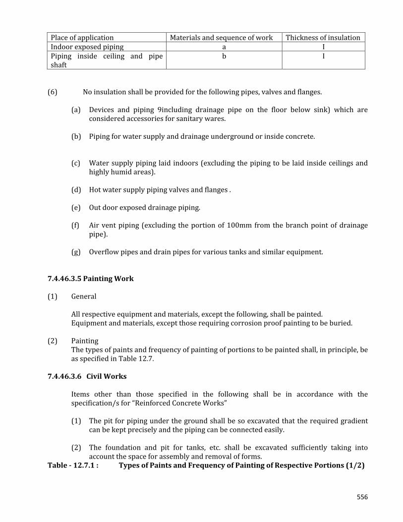
556
Place of application Materials and sequence of work Thickness of insulation Indoor exposed piping a I Piping inside ceiling and pipe shaft
b I
(6) No insulation shall be provided for the following pipes, valves and flanges. (a) Devices and piping 9including drainage pipe on the floor below sink) which are
considered accessories for sanitary wares. (b) Piping for water supply and drainage underground or inside concrete. (c) Water supply piping laid indoors (excluding the piping to be laid inside ceilings and
highly humid areas). (d) Hot water supply piping valves and flanges . (e) Out door exposed drainage piping. (f) Air vent piping (excluding the portion of 100mm from the branch point of drainage
pipe). (g) Overflow pipes and drain pipes for various tanks and similar equipment. 7.4.46.3.5 Painting Work (1) General
All respective equipment and materials, except the following, shall be painted. Equipment and materials, except those requiring corrosion proof painting to be buried.
(2) Painting
The types of paints and frequency of painting of portions to be painted shall, in principle, be as specified in Table 12.7.
7.4.46.3.6 Civil Works
Items other than those specified in the following shall be in accordance with the specification/s for “Reinforced Concrete Works”
(1) The pit for piping under the ground shall be so excavated that the required gradient
can be kept precisely and the piping can be connected easily. (2) The foundation and pit for tanks, etc. shall be excavated sufficiently taking into
account the space for assembly and removal of forms. Table - 12.7.1 : Types of Paints and Frequency of Painting of Respective Portions (1/2)
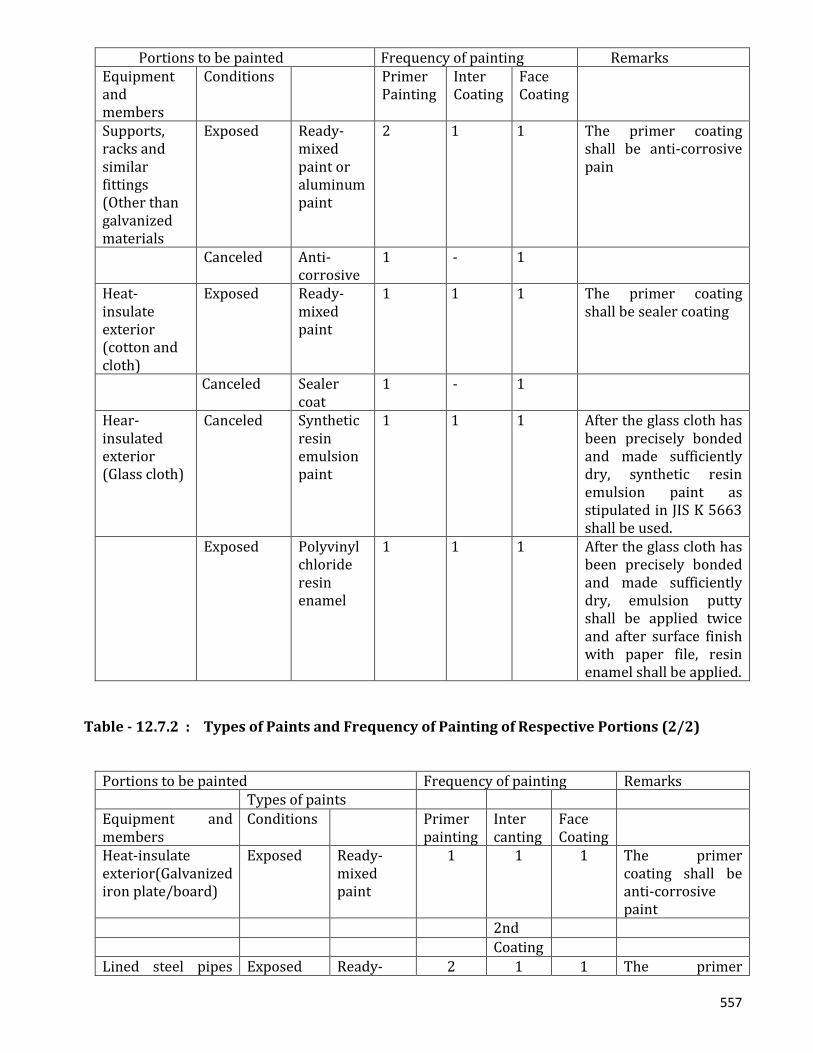
557
Portions to be painted Frequency of painting Remarks Equipment and members
Conditions Primer Painting
Inter Coating
Face Coating
Supports, racks and similar fittings (Other than galvanized materials
Exposed Ready-mixed paint or aluminum paint
2 1 1 The primer coating shall be anti-corrosive pain
Canceled Anti-corrosive
1 - 1
Heat-insulate exterior (cotton and cloth)
Exposed Ready-mixed paint
1 1 1 The primer coating shall be sealer coating
Canceled Sealer coat
1 - 1
Hear-insulated exterior (Glass cloth)
Canceled Synthetic resin emulsion paint
1 1 1 After the glass cloth has been precisely bonded and made sufficiently dry, synthetic resin emulsion paint as stipulated in JIS K 5663 shall be used.
Exposed Polyvinyl chloride resin enamel
1 1 1 After the glass cloth has been precisely bonded and made sufficiently dry, emulsion putty shall be applied twice and after surface finish with paper file, resin enamel shall be applied.
Table - 12.7.2 : Types of Paints and Frequency of Painting of Respective Portions (2/2)
Portions to be painted Frequency of painting Remarks Types of paints Equipment and members
Conditions Primer painting
Inter canting
Face Coating
Heat-insulate exterior(Galvanized iron plate/board)
Exposed Ready-mixed paint
1 1 1 The primer coating shall be anti-corrosive paint
2nd Coating Lined steel pipes Exposed Ready- 2 1 1 The primer
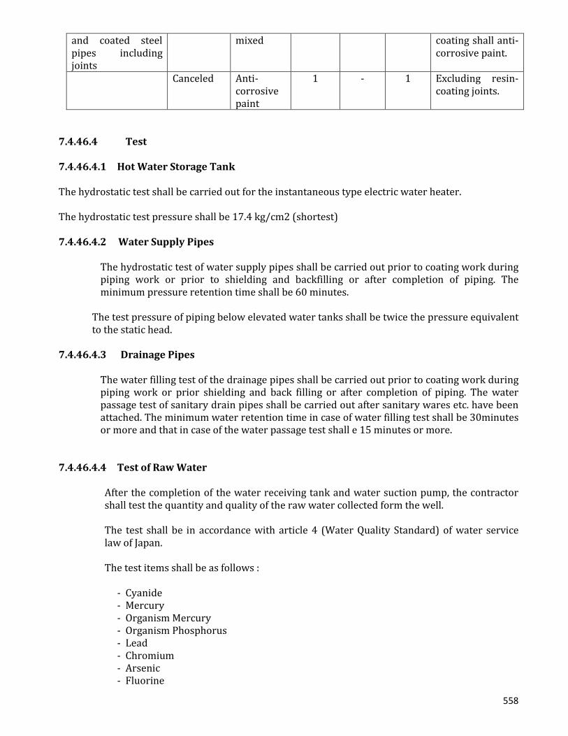
558
and coated steel pipes including joints
mixed coating shall anti-corrosive paint.
Canceled Anti-corrosive paint
1 - 1 Excluding resin-coating joints.
7.4.46.4 Test 7.4.46.4.1 Hot Water Storage Tank The hydrostatic test shall be carried out for the instantaneous type electric water heater. The hydrostatic test pressure shall be 17.4 kg/cm2 (shortest) 7.4.46.4.2 Water Supply Pipes
The hydrostatic test of water supply pipes shall be carried out prior to coating work during piping work or prior to shielding and backfilling or after completion of piping. The minimum pressure retention time shall be 60 minutes.
The test pressure of piping below elevated water tanks shall be twice the pressure equivalent to the static head.
7.4.46.4.3 Drainage Pipes
The water filling test of the drainage pipes shall be carried out prior to coating work during piping work or prior shielding and back filling or after completion of piping. The water passage test of sanitary drain pipes shall be carried out after sanitary wares etc. have been attached. The minimum water retention time in case of water filling test shall be 30minutes or more and that in case of the water passage test shall e 15 minutes or more.
7.4.46.4.4 Test of Raw Water
After the completion of the water receiving tank and water suction pump, the contractor shall test the quantity and quality of the raw water collected form the well.
The test shall be in accordance with article 4 (Water Quality Standard) of water service law of Japan.
The test items shall be as follows :
- Cyanide - Mercury - Organism Mercury - Organism Phosphorus - Lead - Chromium - Arsenic - Fluorine

559
- Cadmium - Nitrogen of nitric acid - Colon bacilli’s
The results of the tests shall be submitted to the Engineer. 7.4.46.4.5 Test of Treated Water
After the completion of drinking water system, the contractor shall test the quality of the treated water collected from the cocks. The test shall be in accordance with article 4 (Water Quality Standard) of water Service Law of Japan.
The test items shall be as follows :
- Turgidity - Chromatizitat - Stench - Taste - Potential of hydrogen - Organic matter - Nitrogen of ammonia - Chlorine Iron - Evaporation - Solvable material - Total hardness - Iron - Manganese - Copper - Zinc
The result of the test shall be submitted to the Engineer. 7.4.47 Air Conditioning and Ventilation Equipment Work 7.4.47.1 General 7.4.47.1.1 Scope
This clause covers the performance of all air conditioning and ventilation equipment works in accordance with the drawings and these specifications.
(1) Air Conditioning Equipment (2) Ventilation Equipment
The contractor shall submit shop drawings of fabricated items to the engineer for approval. The shop drawings shall clearly show the details of fabrication, installations, dimensions, sizes, operation, methods of anchoring and any other pertinent details required for satisfactory installation. The contractor shall submit the result of tests at designated date specified.
7.4.47.1.2 Design Basis of Air Conditioning and Ventilation System

560
(1) Outdoor Maximum Temperature 36o C Dry Bulb Minimum Temperature 28o C Wet bulb Minimum Temperature 12o C Dry bulb (2) Indoor Temperature 25o C Dry bulb Control room 27o C Dry bulb Otherm rooms (summer) 22o C Dry bulb Other rooms (winter) Humidity 60% Control room (Relative humidity) Other rooms 7.4.47.2 Equipment And Materials
The equipment, materials and accessories as specified herein shall be furnished together with spare parts for three (3) years normal operation except as indicate otherwise.
7.4.47.2.1 Package Air Conditioning Units
(1) The Contractor shall furnish and install the package air conditioning units as shown in the drawings. Package air conditioning units shall be factory built and factory tested products.
(2) In this work, tow types of package air conditioning units shall be installed. (3) Air heat source heat pump package air conditioner.
(a) Type Light weight, up right floor standing type. (b) Cabinet Synthetic resin paint baked on finished plates. (c)Insulation Insulation shall be installed to prevent sweating and to muffle sound,
using glass wool on polywreten form. (d) Condenser Air source heat pump condenser. (e) Compressor Compressor (s) shall be serviceable hermetic type equipped with
suitable rubber vibration isolators crank case heaters, liquid line strainer and suction and discharge shut off values.
(f) Air Filter Permanent washable polyvinyl chloride. (g) Heat Exchanger Multi pass cross fined tube. (h) Connections With flare nut or companion flange for field piping. (i) Outdoor Fan Propeller Fan. (j) Evaporator Multi pass cross finned tube

561
(k) Evaporator Fan Multi-brade centrifugal Fan AC- 1 (see drawings) direct drive AC- 2 (see drawings) belt drive (l) Applicable power supplies AC 3-phase 400V 50Hz. (m) Operation switch 3-position push button types and cooling heating selection switch (Ventilating
operation, cooling operation or heating operation. (n) High Pressure Switch This switch cuts out the operation of compressor when the discharge pressure
exceeds the setting. (o) Accessories Spare Parts Refrigerant - for 1 change V. belt - 1 each
7.4.47.2.2 Fans (1) The Contractor shall furnish and install the fans as shown in the drawings. Fans shall be
factory tested products. (2) The capacities of the fans shall be in accordance with fan schedules as shown. Unless
otherwise directed, the fans shall conform to the layouts as shown the drawings. (3) All fans shall be statistically and dynamically balanced to avoid vibration and shall have
blades to secure quiet efficient operation. 7.4.47.2.3 Ducts Duct materials shall conform to the followings: Galvanized steel iron sheet Shape Steel Bolt Nut Gasket for flange 7.4.47.2.4 Refrigerant Pipe Materials and Accessories (1) The pipes shall be of copper. The material shall be as specified in JIS H3603 (Phosphorus
deoxidized copper seamless pipes and tubes) and the dimensions shall be as specified in ASTM B8858L (Hard materials).
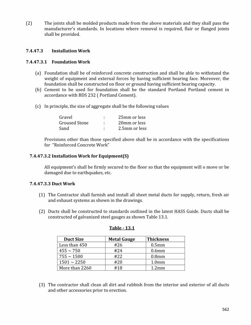
562
(2) The joints shall be molded products made from the above materials and they shall pass the
manufacturer’s standards. In locations where removal is required, flair or flanged joints shall be provided.
7.4.47.3 Installation Work
7.4.47.3.1 Foundation Work
(a) Foundation shall be of reinforced concrete construction and shall be able to withstand the
weight of equipment and external forces by having sufficient bearing face. Moreover, the foundation shall be constructed on floor or ground having sufficient bearing capacity.
(b) Cement to be used for foundation shall be the standard Portland Portland cement in accordance with BDS 232 ( Portland Cement).
(c) In principle, the size of aggregate shall be the following values
Gravel : 25mm or less Groused Stone : 20mm or less Sand : 2.5mm or less
Provisions other than those specified above shall be in accordance with the specifications for “Reinforced Concrete Work”
7.4.47.3.2 Installation Work for Equipment(S)
All equipment’s shall be firmly secured to the floor so that the equipment will o move or be damaged due to earthquakes, etc.
7.4.47.3.3 Duct Work
(1) The Contractor shall furnish and install all sheet metal ducts for supply, return, fresh air and exhaust systems as shown in the drawings.
(2) Ducts shall be constructed to standards outlined in the latest HASS Guide. Ducts shall be
constructed of galvanized steel gauges as shown Table 13.1.
Table - 13.1
Duct Size Metal Gauge Thickness Less than 450 #26 0.5mm 455 ~ 750 #24 0.6mm 755 ~ 1500 #22 0.8mm 1501 ~ 2250 #20 1.0mm More than 2260 #18 1.2mm
(3) The contractor shall clean all dirt and rubbish from the interior and exterior of all ducts and other accessories prior to erection.

563
(4) A flexible connection shall be made between the fan discharge and the adjoining duct work.
(5) Low-velocity ducts shall be installed as follows :
Table - 13.2 : Duct Flanges
Bolt Rivet
Thickness Shape Steel
Max. Pitch Dia. Pitch Dia. Pitch
0.5mm 25x25x3 3.6m 8.0mm 100mm 4.5mm 65mm 0.6 25x25x3 3.6 8.0 100 4.5 65 0.8 30x30x3 2.7 8.0 100 4.5 65 1.0 40x40x3 1.8 8.0 100 4.5 65 1.2 40x40x5 1.8 8.0 100 4.5 65
Table - 13.4 : Duct Hangers
Thickness Shape Steel Steel Rod Dia. Max. Pitch 0.5mm 25 x 25 x 3 9mm 3.0m
0.6 25 x 25 x 3 9 3.0 0.8 30 x 30 x 3 9 3.0 1.0 40 x 40 x 3 9 3.0 1.2 40 x 40 x 5 9 3.0
(6) Spiral Duct
(a) The straight portion of the spiral duct shall be fabricated, using a strip of the
galvanized steel sheet. The nominal size of the spiral duct shall be based on the inside diameter. The tolerance in inside diameter shall be +0 ~ +2 mm in reference to the nominal size. The thickness of the iron strips to be used shall be as indicated in Table 13.5.
Table - 13.5 : Thickness of Spiral Duct
Air Duct Diameter (mm) Thickness (Gauge No.) of iron strips Below 200 0.5mm (#26) Over 200, but below 600 0.6mm (#24) Over 600, but below 800 0.8mm (#22) Over 800, but below 1,000 1.0mm (#20)
The pitch of the side seaming at the straight portion of the spiral duct shall be as indicated in Table 13.6 and the folding width shall be over 6mm.
Table - 13.6 : Side Seaming pitch of spiral Ducts
Air Duct diameter (mm) Seam Pitch (mm)
Below 100 Below 100 Below 1,000 Below 150
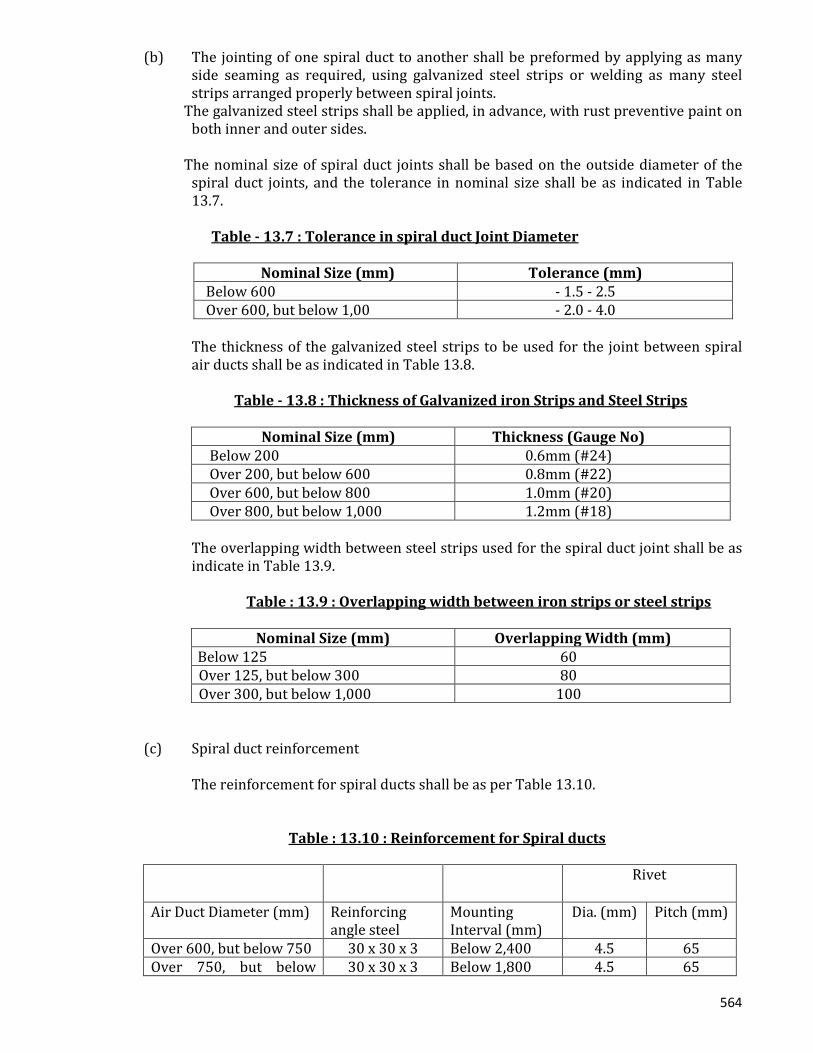
564
(b) The jointing of one spiral duct to another shall be preformed by applying as many side seaming as required, using galvanized steel strips or welding as many steel strips arranged properly between spiral joints.
The galvanized steel strips shall be applied, in advance, with rust preventive paint on both inner and outer sides.
The nominal size of spiral duct joints shall be based on the outside diameter of the
spiral duct joints, and the tolerance in nominal size shall be as indicated in Table 13.7.
Table - 13.7 : Tolerance in spiral duct Joint Diameter
Nominal Size (mm) Tolerance (mm)
Below 600 - 1.5 - 2.5 Over 600, but below 1,00 - 2.0 - 4.0
The thickness of the galvanized steel strips to be used for the joint between spiral air ducts shall be as indicated in Table 13.8.
Table - 13.8 : Thickness of Galvanized iron Strips and Steel Strips
Nominal Size (mm) Thickness (Gauge No)
Below 200 0.6mm (#24) Over 200, but below 600 0.8mm (#22) Over 600, but below 800 1.0mm (#20) Over 800, but below 1,000 1.2mm (#18)
The overlapping width between steel strips used for the spiral duct joint shall be as indicate in Table 13.9.
Table : 13.9 : Overlapping width between iron strips or steel strips
Nominal Size (mm) Overlapping Width (mm)
Below 125 60 Over 125, but below 300 80 Over 300, but below 1,000 100
(c) Spiral duct reinforcement
The reinforcement for spiral ducts shall be as per Table 13.10.
Table : 13.10 : Reinforcement for Spiral ducts
Rivet
Air Duct Diameter (mm) Reinforcing angle steel
Mounting Interval (mm)
Dia. (mm) Pitch (mm)
Over 600, but below 750 30 x 30 x 3 Below 2,400 4.5 65 Over 750, but below 30 x 30 x 3 Below 1,800 4.5 65
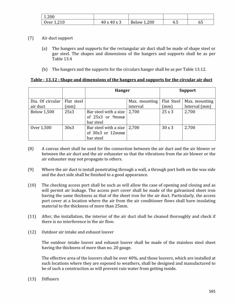
565
1.200 Over 1,210 40 x 40 x 3 Below 1,200 4.5 65
(7) Air duct support
(a) The hangers and supports for the rectangular air duct shall be made of shape steel or gar steel. The shapes and dimensions of the hangers and supports shall be as per Table 13.4
(b) The hangers and the supports for the circulars hanger shall be as per Table 13.12.
Table - 13.12 : Shape and dimensions of the hangers and supports for the circular air duct
Hanger
Support
Dia. Of circular air duct
Flat steel (mm)
Max. mounting interval
Flat Steel (mm)
Max. mounting Interval (mm)
Below 1,500 25x3 Bar steel with a size of 25x3 or 9mmø bar steel
2,700 25 x 3 2,700
Over 1,500 30x3 Bar steel with a size of 30x3 or 12mmø bar steel
2,700 30 x 3 2.700
(8) A canvas sheet shall be used for the connection between the air duct and the air blower or
between the air duct and the air exhauster so that the vibrations from the air blower or the air exhauster may not propagate to others.
(9) Where the air duct is install penetrating through a wall, a through part both on the was side
and the duct side shall be finished to a good appearance. (10) The checking access port shall be such as will allow the case of opening and closing and as
will permit air leakage. The access port cover shall be made of the galvanized sheet iron having the same thickness as that of the sheet iron for the air duct. Particularly, the access port cover at a location where the air from the air conditioner flows shall have insulating material to the thickness of more than 25mm.
(11) After, the installation, the interior of the air duct shall be cleaned thoroughly and check if
there is no interference in the air flow. (12) Outdoor air intake and exhaust louver The outdoor intake louver and exhaust louver shall be made of the stainless steel sheet
having the thickness of more than no. 20 gauge. The effective area of the louvers shall be over 40%, and those louvers, which are installed at
such locations where they are exposed to weathers, shall be designed and manufactured to be of such a construction as will prevent rain water from getting inside.
(13) Diffusers
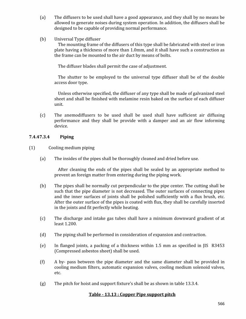
566
(a) The diffusers to be used shall have a good appearance, and they shall by no means be allowed to generate noises during system operation. In addition, the diffusers shall be designed to be capable of providing normal performance.
(b) Universal Type diffuser The mounting frame of the diffusers of this type shall be fabricated with steel or iron
plate having a thickness of more than 1.0mm, and it shall have such a construction as the frame can be mounted to the air duct by means of bolts.
The diffuser blades shall permit the case of adjustment. The shutter to be employed to the universal type diffuser shall be of the double
access door type. Unless otherwise specified, the diffuser of any type shall be made of galvanized steel
sheet and shall be finished with melamine resin baked on the surface of each diffuser unit.
(c) The anemodiffusers to be used shall be used shall have sufficient air diffusing
performance and they shall be provide with a damper and an air flow informing device.
7.4.47.3.4 Piping (1) Cooling medium piping
(a) The insides of the pipes shall be thoroughly cleaned and dried before use. After cleaning the ends of the pipes shall be sealed by an appropriate method to
prevent an foreign matter from entering during the piping work. (b) The pipes shall be normally cut perpendicular to the pipe center. The cutting shall be
such that the pipe diameter is not decreased. The outer surfaces of connecting pipes and the inner surfaces of joints shall be polished sufficiently with a flux brush, etc. After the outer surface of the pipes is coated with flux, they shall be carefully inserted in the joints and fit perfectly while heating.
(c) The discharge and intake gas tubes shall have a minimum downward gradient of at
least 1.200. (d) The piping shall be performed in consideration of expansion and contraction. (e) In flanged joints, a packing of a thickness within 1.5 mm as specified in JIS R3453
(Compressed asbestos sheet) shall be used. (f) A by- pass between the pipe diameter and the same diameter shall be provided in
cooling medium filters, automatic expansion valves, cooling medium solenoid valves, etc.
(g) The pitch for hoist and support fixture’s shall be as shown in table 13.3.4.
Table - 13.13 : Copper Pipe support pitch
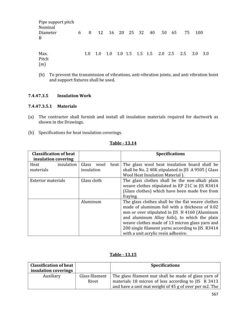
567
Pipe support pitch Nominal Diameter 6 8 12 16 20 25 32 40 50 65 75 100 B Max. 1.0 1.0 1.0 1.0 1.5 1.5 1.5 2.0 2.5 2.5 3.0 3.0 Pitch (m)
(h) To prevent the transmission of vibrations, anti-vibration joints, and anti vibration hoist
and support fixtures shall be used. 7.4.47.3.5 Insulation Work 7.4.47.3.5.1 Materials (a) The contractor shall furnish and install all insulation materials required for ductwork as
shown in the Drawings. (b) Specifications for heat insulation coverings.
Table - 13.14
Classification of heat insulation covering
Specifications
Heat insulation materials
Glass wool heat insulation
The glass wool heat insulation board shall be shall be No. 2 40K stipulated in JIS A 9505 ( Glass Wool Heat Insulation Material ).
Exterior materials Glass cloth The glass clothes shall be the non-alkali plain weave clothes stipulated in EP 21C in JIS R3414 (Glass clothes) which have been made free from fraying.
Aluminum The glass clothes shall be the flat weave clothes made of aluminum foil with a thickness of 0.02 mm or over stipulated in JIS H 4160 (Aluminum and aluminum Alloy foils), to which the plain weave clothes made of 13 micron glass yarn and 200 single filament yarns according to JIS R3414 with a unit acrylic resin adhesive.
Table - 13.15
Classification of heat insulation coverings
Specifications
Auxiliary Glass filament Rivet
The glass filament mat shall be made of glass yarn of materials 18 micron of less according to JIS R 3413 and have a unit mat weight of 45 g of over per m2. The

568
rivet shall be made of the washer made of galvanized steel plate to which a nail with a length to be changed depending upon the thickness of heat insulation materials is built in, or the copper plated nail for spot welding, and have a strength sufficient to bear the insulation materials.
Steel frame In principle, the steel frame shall be made of steel plate with a standard plate thickness of 0.4 mm or over as stipulated in JIS G 3302 (Galvanized sheets)
Adhesive In principle, the acrylic emulsion adhesive shall be used for bonding of glass clothes, glass filament mat and aluminum glass clothes, and the chloroprene rubber adhesive shall be used for bonding of rivet.
(3) Materials and procedures depending upon the types of heat insulation work.
Classification of insulation work Order of insulation work Insulation of exposed interior 1. Rivetting 2. Heat insulation board with a thickness of 50mm 3. Corner patch and seal-up 4. Adhesive 5. Glass clothes Indoor concealing 1. Rivet 2. Heat insulation board with a thickness of 25 mm 3. Corner patch and seal-up 4. Adhesive 5. Aluminum Glass clothes
Note : The galvanized steel plate with a thickness of 0.2 mm or over shall be used for corner patch, and the glass filament mat shall be used for seal- up. 7.4.47.3.5.2 Execution (1) The mutual clearance between the respective insulation shall not include the thickness of
exterior materials or auxiliary materials. (2) The mutual clearance between the respective insulation shall as small possible, and no
overlapping joints shall be provided on the same line. (3) In principle, two rivets shall be driven into the lower and side surfaces and one rivet into
the upper surface of the air duct at intervals of 300mm each. (4) The portion or air duct penetrating through the floor shall be covered with stainless steel
from the floor surface to height of up to 150mm in order to protect the insulation (5) The outermost ends of the insulation shall be protected as required depending upon the
materials and purpose of heat insulation.
569
(6) Heat insulation work for inspection doors, etc. of equipment requiring such insulation shall be carried out so as not to cause hindrance during opening and closing of such doors, etc. nor deterioration of the said heat insulation.
7.4.47.3.6 Painting Work 7.4.47.3.6.1 General (1) All equipment and materials, except for the following , shall be painted. (a) Surfaces other than galvanized surfaces (b) Galvanized portions which are normally concealed (2) All equipment and materials requiring inspection shall be painted after inspection. 7.4.47.3.6.2 Painting The types of paints and frequency of painting of the respective portions shall, in principle, be as specified in Clause 11.3.5 Unless specified in this table, such painting shall be carried out according to similar items taking into account the work purposes, materials and other conditions. 7.4.47.4 Tests 7.4.47.4.1 Piping (1) The refrigerator shall pass the air-tightness and pressure withstand tests. (2) The refrigerators shall be test operated in the factory and careful investigations concerning
performance, noise, vibrations, etc. shall be performed. After it is confirmed that the tests have been passed, the refrigerator shall be shipped after applying rust-proof paint.
(3) After installation, the refrigerators shall be test operated. (4) After completing of the refrigerant piping, an air-tightness test shall be performed using
carbon dioxide, nitrogen, dry air, etc. After the air-tightness test, the entire system shall under-go high vacuum evaporation to remove all water. After this dehydration treatment, a cooling medium leak test shall be performed according to the inspection of the Engineer.
7.4.47.4.2 Duct After completing the air duct installation, the air duct system shall have and air blow test in the presence of the Engineer. Unless otherwise specified, all of equipment, materials and execution shall be as stipulated in “Indoor Lighting System”. 7.4.48 Secondary-Electrical Wiring 7.4.48.1 General (1) The contractor shall furnish and install the control panels, switches, receptacles, electrical
conduit pipes, wires, outlet box for secondary wiring equipment as shown in the Drawings.

570
(2) Motors used in cooling equipment, blowers pumps, etc. shall all be included in this
equipment work. (3) Unless otherwise specified, the wire conduit and wiring work in the primary side shall all
be performed as separate electrical equipment work. However :
(a) Secondary side wire conduit and wiring work for cooling equipment operating panels and below shall all be part of the work of the equipment concerned.
(b) Wire conduit and wiring work related to the automatic control of air conditioning
equipment shall all be part of the work of the equipment concerned. (c) Insufficient water level alarm equipment for water supply tanks, etc. shall be a part
of the work of the equipment concerned. (4) Unless otherwise indicated in this clause, all of equipment, materials and execution shall be
as stipulated in “Indoor Lightening Plug and Telephone Piping System” 7.4.48.2 Equipment And Materials (1) Cables shall be as shown in Table - 14.1.
Table - 14.1(1)
Items Code No Type Letter Control cable JIS C3401 Polyvinyl Chloride CVV Insulated and Sheathed control Cables Cross-linked JIS C3606 Cross-linked Polyethylene CV Polyethylene Insulated Cable Cable
(2) The electrical equipment and materials shall meet the standards of the Japanese Electrical
manufacturers Association (JEM) in addition to these specifications. (3) Motors
(a) Unless otherwise specified, AC motors shall meet the specifications in Table 14.2.
Motor Specifications JIS 4201 Low-Voltage Three Phase Induction Motor Voltage 400 G Insulation class E
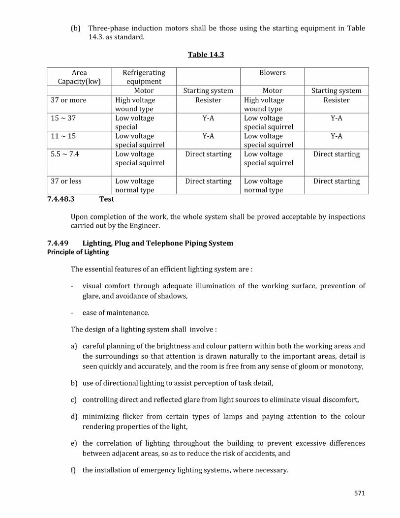
571
(b) Three-phase induction motors shall be those using the starting equipment in Table 14.3. as standard.
Table 14.3
Area
Capacity(kw) Refrigerating
equipment Blowers
Motor Starting system Motor Starting system 37 or more High voltage
wound type Resister High voltage
wound type Resister
15 ~ 37 Low voltage special
Y-A Low voltage special squirrel
Y-A
11 ~ 15 Low voltage special squirrel
Y-A Low voltage special squirrel
Y-A
5.5 ~ 7.4 Low voltage special squirrel
Direct starting Low voltage special squirrel
Direct starting
37 or less Low voltage normal type
Direct starting Low voltage normal type
Direct starting
7.4.48.3 Test
Upon completion of the work, the whole system shall be proved acceptable by inspections carried out by the Engineer.
7.4.49 Lighting, Plug and Telephone Piping System Principle of Lighting
The essential features of an efficient lighting system are :
- visual comfort through adequate illumination of the working surface, prevention of glare, and avoidance of shadows,
- ease of maintenance.
The design of a lighting system shall involve :
a) careful planning of the brightness and colour pattern within both the working areas and the surroundings so that attention is drawn naturally to the important areas, detail is seen quickly and accurately, and the room is free from any sense of gloom or monotony,
b) use of directional lighting to assist perception of task detail,
c) controlling direct and reflected glare from light sources to eliminate visual discomfort,
d) minimizing flicker from certain types of lamps and paying attention to the colour rendering properties of the light,
e) the correlation of lighting throughout the building to prevent excessive differences between adjacent areas, so as to reduce the risk of accidents, and
f) the installation of emergency lighting systems, where necessary.
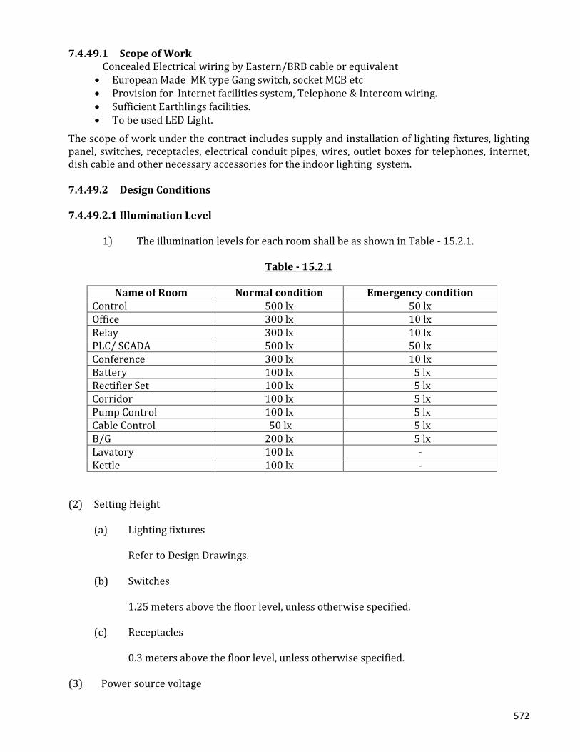
572
7.4.49.1 Scope of Work
Concealed Electrical wiring by Eastern/BRB cable or equivalent • European Made MK type Gang switch, socket MCB etc • Provision for Internet facilities system, Telephone & Intercom wiring. • Sufficient Earthlings facilities. • To be used LED Light.
The scope of work under the contract includes supply and installation of lighting fixtures, lighting panel, switches, receptacles, electrical conduit pipes, wires, outlet boxes for telephones, internet, dish cable and other necessary accessories for the indoor lighting system. 7.4.49.2 Design Conditions 7.4.49.2.1 Illumination Level 1) The illumination levels for each room shall be as shown in Table - 15.2.1.
Table - 15.2.1
Name of Room Normal condition Emergency condition Control 500 lx 50 lx Office 300 lx 10 lx Relay 300 lx 10 lx PLC/ SCADA 500 lx 50 lx Conference 300 lx 10 lx Battery 100 lx 5 lx Rectifier Set 100 lx 5 lx Corridor 100 lx 5 lx Pump Control 100 lx 5 lx Cable Control 50 lx 5 lx B/G 200 lx 5 lx Lavatory 100 lx - Kettle 100 lx -
(2) Setting Height (a) Lighting fixtures Refer to Design Drawings. (b) Switches 1.25 meters above the floor level, unless otherwise specified. (c) Receptacles 0.3 meters above the floor level, unless otherwise specified. (3) Power source voltage
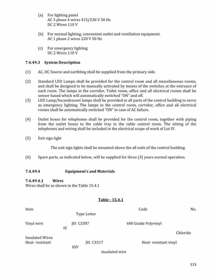
573
(a) For lighting panel AC 3 phase 4 wires 415/230 V 50 Hz DC 2 Wires 110 V (b) For normal lighting, convenient outlet and ventilation equipment. AC 1 phase 2 wires 220 V 50 Hz (c) For emergency lighting DC 2 Wires 110 V 7.4.49.3 System Description (1) AC, DC Source and earthling shall be supplied from the primary side. (2) Standard LED Lamps shall be provided for the control room and all miscellaneous rooms,
and shall be designed to be manually activated by means of the switches at the entrance of each room. The lamps in the corridor, Toilet room, office and all electrical rooms shall be sensor based which will automatically switched “ON” and off.
(3) LED Lamp/Incandescent lamps shall be provided in all parts of the control building to serve as emergency lighting. The lamps in the control room, corridor, office and all electrical rooms shall be automatically switched “ON” in case of AC failure.
(4) Outlet boxes for telephones shall be provided for the control room, together with piping
from the outlet boxes to the cable tray in the cable control room. The sitting of the telephones and wiring shall be included in the electrical scope of work of Lot IV.
(5) Exit sign light The exit sign lights shall be mounted above the all exits of the control building. (6) Spare parts, as indicated below, will be supplied for three (3) years normal operation. 7.4.49.4 Equipment’s and Materials 7.4.49.4.1 Wires Wires shall be as shown in the Table 15.4.1
Table - 15.4.1 Item Code No. Type Letter Vinyl wire JIS C3307 600 Grade Polyvinyl IV Chloride Insulated Wires Heat- resistant JIS C3317 Heat- resistant vinyl HIV Insulated wire

574
HIV wires shall be used in the DC circuit. 7.4.49.4.2 Wire Connectors Wire connectors for indoor wiring shall be in accordance with JIS C2810 or equivalent BDS 7.4.49.4.3 Metal Conduit and Fittings Metal conduit and fittings shall be in accordance with the Table 15.4.3, and the conduit shall be of heavy gauge type.
Table 15.4.3 Item Code No. Designation Conduit JIS C8305 Rigid metal Conduit ( heavy gauge) Coupling JIS C8330 Coupling for Rigid Metal Conduit Normal Bend JIS C8330 Elbows for Rigid Metal conduit Bushing JIS C8331 Bushing for Rigid metal Conduit Locknut JIS C8333 Locknuts for Rigid Metal Conduit Saddle JIS C8334 Saddles for Rigid Metal Conduit Universal JIS C8335 Universal Fittings for Rigid metal
Conduit
Outlet Box JIS C8337 Out Boxes for Rigid metal Conduit Switch Box JIS C8337 Switch Boxes for Rigid Metal Conduit Concrete Box JIS C8338 Concrete Boxes for Rigid Metal Conduit Box Cover JIS C8339 Box covers for Rigid Metal Conduit Insulated Bushing JIS C8347 Insulated Bushing for
rigid Metal Conduit
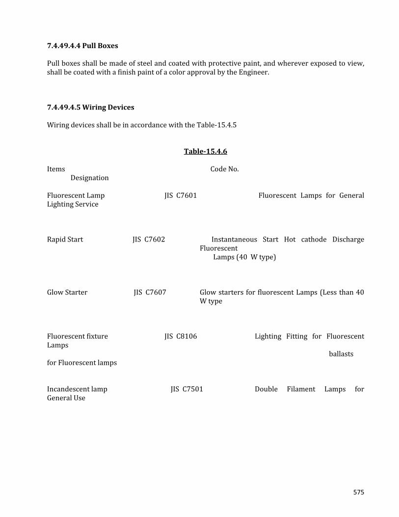
575
7.4.49.4.4 Pull Boxes Pull boxes shall be made of steel and coated with protective paint, and wherever exposed to view, shall be coated with a finish paint of a color approval by the Engineer. 7.4.49.4.5 Wiring Devices Wiring devices shall be in accordance with the Table-15.4.5
Table-15.4.6
Items Code No. Designation Fluorescent Lamp JIS C7601 Fluorescent Lamps for General Lighting Service Rapid Start JIS C7602 Instantaneous Start Hot cathode Discharge
Fluorescent Lamps (40 W type)
Glow Starter JIS C7607 Glow starters for fluorescent Lamps (Less than 40
W type
Fluorescent fixture JIS C8106 Lighting Fitting for Fluorescent Lamps ballasts for Fluorescent lamps Incandescent lamp JIS C7501 Double Filament Lamps for General Use

576
7.4.49.4.6 Lighting Fixtures (a) In Principle shapes and dimensions shall be in accordance with the Drawings. Catalogs and
shop drawings shall be submitted to the Engineer for approval. (b) Lighting fixtures for emergency use shall be as specified by BCJ (Articles rated by the
Building Center of Japan), or approved equal. 7.4.49.4.7 Lighting Panel Shapes, electrical characteristics, types capacities of circuit breakers, and the system of operation shall be in accordance with the Drawings. The panel shall made of steel plate with a thickness of more than 1.6mm (body) and 2.3 mm (door) respectively. The finish shall be painted with a color approved by the Engineer. Catalogs and shop drawings shall be submitted to the Engineer for approval. 7.4.49.4.8 Over Current Protectors Molded case circuit breakers and residual current protective devices shall be of European Standard used in the lighting panel 7.4.49.5 Indoor Wiring 7.4.49.5.1 Rigid Metal Conduit (1) Installation
(a) Imbedding or conduit laying shall be so made that the strength and structure of the building is not affected.
(b) Cut ends of conduit shall be neatly and smoothly finished by instrument such as a
reamer.

577
(c) Conduit shall be bent at a radius of more than six (6) times the internal diameter of the conduit conduit running between outlets and pulling boxes shall not have more than the equivalent of four 90o bends.
(d) A pull box or junction box shall be installed to protect conduit exceeding 30 meters
in length and at the points required. (e) In general, a switch or outlet box shall be used at all points where a switch,
receptacle (socket) or lighting fixture is to be provided. (f) Where low voltage metal conduit is enclose in proximity to or crosses
communication wiring, metallic water pipe or gas pipe, the work shall be so done that direct contact is avoided.
(2) Connection of conduits
Conduit and fittings shall be perfectly connected, both physically and electrically, and the conductor resistance shall be preferably dept within 2 ohms between grounding conductor and the end metal conduit.
(3) Pull Boxes and Junction Boxes
(a) Shape and type of these boxes shall suit the place of installation and a steel plate or more than 1.2mm in thickness shall be used.
(b) Boxes shall have adequate dimensions well matching the number or conduits
connected and the condition of connecting or pulling wires. (c) Where the box is covered or concealed in structural material, access to the box shall
be made possible to facilitate inspection. (4) Installation of feeder conduits
(a) Exposed main conduit shall, in principle, run parallel with wall or ceiling. (b) Metals supports for conduit in concrete building shall have a proper fixing insert or
bolt previously embedded in the concrete. (c) Spacing between metal inserts or bolts to support conduit shall in principle, be
approximately 2 meters. (5) Painting, Protection and cleaning of Conduit
(a) Where the plated or painted surface of conduit, metal support or box has peeled off, it shall be touched up with protective paint.
578
(b) Conduit shall be sufficiently protected against entry of moisture, water, dust etc. and
the cut end of conduit shall be bush be capped, wood plugged or covered with rag, etc. Whenever concrete work is in progress.
(c) Conduit and boxes shall be well cleaned and the conductivity checked after removal
of the forms.
(6) Wire Pulling
(a) Connection of wire shall not be made inside metal conduit. Connection shall be made in metal box, junction box or distribution board.
(b) Wire shall be pulled through conduit after the inside of conduit has been cleaned
and when each of conduit has been capped with bushing. Cleaning shall be performed in such a manner that walls, ceilings, etc. around the conduit are not stained or spoiled in any way.
(c) In all cases, all wires stemming from one circuit shall be accommodated in the same
conduit for A.C circuit work, except where a balanced condition is electro-magnetically attained by accommodating both lines of the same polarity within the same conduit.
7.4.49.6 Installations 7.4.49.6.1 Installation of Lighting Fixtures (a) Heavy lighting fixtures shall be firmly supported using inserts, studs or bolts, attachments
and if necessary shall be provided with a means to prevent swinging by using wood screw, etc.
(b) Lighting fixtures shall be installed horizontally or vertically in a workmanlike manner and
shall be so located as to not interfere with inspection of related equipment. 7.4.49.6.2 Installation of Lighting Panel Lighting panel shall be installed firmly on walls or other surfaces in a workmanlike manner, and shall be so located as to not interfere with inspection of related equipment.
579
7.4.49.6.3 Test A performance test shall be made be made after installation of equipment has been completed. 7.4.49.7 Grounding 7.4.49.7.1 Grounding Resistance Grounding resistance shall be 10 ohms on less, unless otherwise specified. 7.4.49.7.2 Electrical Works to Be Grounded Except for specific instances, all electrical that the respective grounding resistance values are kept at specified values throughout the year despite seasonal changes. (a) No grounding is required for steel base, metal box and steel frame of equipment is operated
on less than AC150 V (Voltage to ground) and is installed at a dry location. (b) Metal conduit and metal accessories (c) Metal enclosure accommodating the discharge lamp ballast and the metal parts or a
discharge lamp lighting fixture, except where grounding is required and/or when so directed by Engineer, shall be grounded.
.