718 IEEE TRANSACTIONS ON ROBOTICS, VOL. 27, NO. 4,...
12
718 IEEE TRANSACTIONS ON ROBOTICS, VOL. 27, NO. 4, AUGUST 2011 Programmable Assembly With Universally Foldable Strings (Moteins) Kenneth C. Cheung, Erik D. Demaine, Jonathan R. Bachrach, and Saul Griffith Abstract—Understanding how linear strings fold into 2-D and 3-D shapes has been a long sought goal in many fields of both academia and industry. This paper presents a technique to design self-assembling and self-reconfigurable systems that are composed of strings of very simple robotic modules. We show that physical strings that are composed of a small set of discrete polygonal or polyhedral modules can be used to programmatically generate any continuous area or volumetric shape. These modules can have one or two degrees of freedom (DOFs) and simple actuators with only two or three states. We describe a subdivision algorithm to produce universal polygonal and polyhedral string folding schemas, and we prove the existence of a continuous motion to reach any such folding. This technique is validated with dynamics simulations as well as experiments with chains of modules that pack on a regular cubic lattice. We call robotic programmable universally foldable strings “moteins” as motorized proteins. Index Terms—Biologically inspired robots, cellular and modular robots, folding robots, kinematics, micro/nano robots. I. INTRODUCTION T HE EXACT method by which a 1-D code translates into a 3-D structure in biological protein folding is currently unknown (although science is making great progress). Still, the complexity and diversity of 3-D structures that are accessible by this 1-D to 3-D approach have long been appreciated [1]. This paper seeks to demonstrate the completeness and appli- cability of simple forms of the 1-D to 3-D strategy in design- ing new robotic systems that can take any shape. For clarity, we will primarily discuss Euclidean space-filling curves in 2- D and 3-D, with a brief analysis of more general space filling curves, within the context of the presented algorithms. Further, Manuscript received February 21, 2010; revised September 11, 2010 and January 18, 2011; accepted March 16, 2011. Date of publication June 9, 2011; date of current version August 10, 2011. This paper was recommended for publication by Associate Editor A. Ijspeert and Editor J.-P. Laumond upon evaluation of the reviewers’ comments. This work was supported by the Massachusetts Institute of Technology Center for Bits and Atoms and the U.S. Army Research Office under Grant W911NF-08-1-0254 (Programmable Matter). K. C. Cheung is with Massachusetts Institute of Technology Center for Bits and Atoms, Cambridge, MA 02139 USA (e-mail: [email protected]). E. D. Demaine is with Massachusetts Institute of Technology Center for Bits and Atoms and the Massachusetts Institute of Technology Computer Science and Artificial Intelligence Laboratory, Cambridge, MA 02139 USA (e-mail: [email protected]). J. R. Bachrach and S. Griffith are with Massachusetts Institute of Technol- ogy Center for Bits and Atoms and Otherlab, San Francisco, CA 94107 USA (e-mail: [email protected]; [email protected]). This paper has supplementary downloadable material available at http:// ieeexplore.ieee.org. Color versions of one or more of the figures in this paper are available online at http://ieeexplore.ieee.org. Digital Object Identifier 10.1109/TRO.2011.2132951 we show the ability of these systems to geometrically achieve the proposed results through continuous motion without self- intersection. While the examples that are provided address Eu- clidean orthogonal lattices in 2-D and 3-D, the concepts and algorithms are extensible to non-Euclidean lattices and space tilings (many of the experiments and simulations have been successfully repeated with space-filling right-angle-tetrahedron chains). Powerful strategies already exist to design discretized robotic systems with units that pack onto a lattice [2]. Many exam- ples have been built (Atron, Fracta, I-Cube, M-Tran, Molecube, Telecube, Superbot, Microunit, Crystalline, Robotic Molecule, Stochastic Modular Robots, etc.), utilizing various schemes for unit attachment, detachment, and self-manipulation [3]. In this study, we propose that introducing a connectivity constraint— that all units of a lattice robot are chained together as a string, configuring to a space-filling curve—greatly simplifies the me- chanical design of lattice robots, while retaining the ability to universally reconfigure. The essential ability of units in a meta- morphic system to travel across, attach to, and detach from other units [4] becomes unnecessary. As each unit is constrained by the previous unit (which is in turn constrained by its previous unit), transformational periodicity and symmetry—which are key aspects of universally reconfigurable lattice systems [2]— can be maintained with one degree of freedom (DOF) per unit. There is also prior work on folding robots [5] and robotic origami [6], which shows the promise of serially performing simple and single-DOF operations to form complex shapes. Recent work has shown self-folding planar origami sheets [7]. The main distinction, here, is that our approach folds 1-D to 3-D, while classical and robotic origami folds 2-D to 3-D. We chose to work toward the simplest possible unit design, with low material loss in configuration. Planar folding (2-D to 3-D) results in a maximum of square loss of material to reach some shapes, whereas string folding (1-D to 3-D) results in a constant- factor loss for all shapes, as we explain next. II. FOLDING SCHEMA Peano [8] and Hilbert [9] first constructed 2-D and 3-D space- filling curves. These recursive infinite curves define a connected linear mapping of 2-D or 3-D space. They have been of interest across many areas of mathematics and information science. It is known that a connected series of smaller and self-similar objects (polygons in 2-D and polyhedra in 3-D) connected at similar hinges can exist in a chained configuration that takes the form of any pixellated 2-D [10], [11] or voxellated 3-D [12] object. While, in 2-D, some of these chains are known to continuously fold without intersection into all pixellated 2-D shapes [13], no 1552-3098/$26.00 © 2011 IEEE
Transcript of 718 IEEE TRANSACTIONS ON ROBOTICS, VOL. 27, NO. 4,...

718 IEEE TRANSACTIONS ON ROBOTICS, VOL. 27, NO. 4, AUGUST 2011
Programmable Assembly With UniversallyFoldable Strings (Moteins)
Kenneth C. Cheung, Erik D. Demaine, Jonathan R. Bachrach, and Saul Griffith
Abstract—Understanding how linear strings fold into 2-D and3-D shapes has been a long sought goal in many fields of bothacademia and industry. This paper presents a technique to designself-assembling and self-reconfigurable systems that are composedof strings of very simple robotic modules. We show that physicalstrings that are composed of a small set of discrete polygonal orpolyhedral modules can be used to programmatically generate anycontinuous area or volumetric shape. These modules can have oneor two degrees of freedom (DOFs) and simple actuators with onlytwo or three states. We describe a subdivision algorithm to produceuniversal polygonal and polyhedral string folding schemas, andwe prove the existence of a continuous motion to reach any suchfolding. This technique is validated with dynamics simulations aswell as experiments with chains of modules that pack on a regularcubic lattice. We call robotic programmable universally foldablestrings “moteins” as motorized proteins.
Index Terms—Biologically inspired robots, cellular and modularrobots, folding robots, kinematics, micro/nano robots.
I. INTRODUCTION
THE EXACT method by which a 1-D code translates intoa 3-D structure in biological protein folding is currently
unknown (although science is making great progress). Still, thecomplexity and diversity of 3-D structures that are accessibleby this 1-D to 3-D approach have long been appreciated [1].
This paper seeks to demonstrate the completeness and appli-cability of simple forms of the 1-D to 3-D strategy in design-ing new robotic systems that can take any shape. For clarity,we will primarily discuss Euclidean space-filling curves in 2-D and 3-D, with a brief analysis of more general space fillingcurves, within the context of the presented algorithms. Further,
Manuscript received February 21, 2010; revised September 11, 2010 andJanuary 18, 2011; accepted March 16, 2011. Date of publication June 9, 2011;date of current version August 10, 2011. This paper was recommended forpublication by Associate Editor A. Ijspeert and Editor J.-P. Laumond uponevaluation of the reviewers’ comments. This work was supported by theMassachusetts Institute of Technology Center for Bits and Atoms and theU.S. Army Research Office under Grant W911NF-08-1-0254 (ProgrammableMatter).
K. C. Cheung is with Massachusetts Institute of Technology Center for Bitsand Atoms, Cambridge, MA 02139 USA (e-mail: [email protected]).
E. D. Demaine is with Massachusetts Institute of Technology Center for Bitsand Atoms and the Massachusetts Institute of Technology Computer Scienceand Artificial Intelligence Laboratory, Cambridge, MA 02139 USA (e-mail:[email protected]).
J. R. Bachrach and S. Griffith are with Massachusetts Institute of Technol-ogy Center for Bits and Atoms and Otherlab, San Francisco, CA 94107 USA(e-mail: [email protected]; [email protected]).
This paper has supplementary downloadable material available at http://ieeexplore.ieee.org.
Color versions of one or more of the figures in this paper are available onlineat http://ieeexplore.ieee.org.
Digital Object Identifier 10.1109/TRO.2011.2132951
we show the ability of these systems to geometrically achievethe proposed results through continuous motion without self-intersection. While the examples that are provided address Eu-clidean orthogonal lattices in 2-D and 3-D, the concepts andalgorithms are extensible to non-Euclidean lattices and spacetilings (many of the experiments and simulations have beensuccessfully repeated with space-filling right-angle-tetrahedronchains).
Powerful strategies already exist to design discretized roboticsystems with units that pack onto a lattice [2]. Many exam-ples have been built (Atron, Fracta, I-Cube, M-Tran, Molecube,Telecube, Superbot, Microunit, Crystalline, Robotic Molecule,Stochastic Modular Robots, etc.), utilizing various schemes forunit attachment, detachment, and self-manipulation [3]. In thisstudy, we propose that introducing a connectivity constraint—that all units of a lattice robot are chained together as a string,configuring to a space-filling curve—greatly simplifies the me-chanical design of lattice robots, while retaining the ability touniversally reconfigure. The essential ability of units in a meta-morphic system to travel across, attach to, and detach from otherunits [4] becomes unnecessary. As each unit is constrained bythe previous unit (which is in turn constrained by its previousunit), transformational periodicity and symmetry—which arekey aspects of universally reconfigurable lattice systems [2]—can be maintained with one degree of freedom (DOF) per unit.
There is also prior work on folding robots [5] and roboticorigami [6], which shows the promise of serially performingsimple and single-DOF operations to form complex shapes.Recent work has shown self-folding planar origami sheets [7].The main distinction, here, is that our approach folds 1-D to3-D, while classical and robotic origami folds 2-D to 3-D. Wechose to work toward the simplest possible unit design, withlow material loss in configuration. Planar folding (2-D to 3-D)results in a maximum of square loss of material to reach someshapes, whereas string folding (1-D to 3-D) results in a constant-factor loss for all shapes, as we explain next.
II. FOLDING SCHEMA
Peano [8] and Hilbert [9] first constructed 2-D and 3-D space-filling curves. These recursive infinite curves define a connectedlinear mapping of 2-D or 3-D space. They have been of interestacross many areas of mathematics and information science. It isknown that a connected series of smaller and self-similar objects(polygons in 2-D and polyhedra in 3-D) connected at similarhinges can exist in a chained configuration that takes the formof any pixellated 2-D [10], [11] or voxellated 3-D [12] object.While, in 2-D, some of these chains are known to continuouslyfold without intersection into all pixellated 2-D shapes [13], no
1552-3098/$26.00 © 2011 IEEE

CHEUNG et al.: PROGRAMMABLE ASSEMBLY WITH UNIVERSALLY FOLDABLE STRINGS (MOTEINS) 719
Fig. 1. (a) Spanning tree is shown with red lines that connect the nodes (red dots) at the center of each “pixel.” (b) Subdivision of each pixel into four “subpixels,”each group of which forms a Hamiltonian path, and any assembly of which contains a Hamiltonian path (the yellow tile shows the construction by the addition ofnew tiles). (c) Six possible “pixel” configurations and their “subpixels” demonstrating edge connectivity. (d) Eight cubic voxels, arranged in constructive lattice,each comprised of eight cubic subvoxels with Hamiltonian loops of connectivity shown in green and blue. (e) Constructive connection between two paths to makea circuit that includes all subvoxels of the original two. (f) Fully face connected voxel, connected to all six adjacent voxels, enabling a connected path to allsurrounding voxels from any given voxel.
prior results attain continuous foldability with a method that isgeneralizable across 2-D and 3-D. This is a goal that we achievehere.
We start by viewing the collection of pixels as a graph. Thenodes of the graph are the centers of the pixels, and the edgesin the graph connect adjacent pixels. In order to construct theshape by folding, it must be possible to connect all of the nodesin the graph through a Hamiltonian (single and nonintersect-ing) path. Not all graphs have Hamiltonian paths; for instance,consider the yellow dog shape in Fig. 1(a), which does not con-tain a Hamiltonian path. It is well known that even determiningwhether a graph has one is an NP-complete problem [14].
We can get around the problem with an efficient subdivisionalgorithm [11], by replacing each pixel with a collection of sub-units that contains a Hamiltonian circuit. For our example ofsquare macrotiles, the simplest subdivision method that satis-fies these requirements is to divide each square equally into foursmaller squares, thus increasing the number of pixels by a fac-tor of 4. To illustrate what we obtain, we consider the spanningtree of an original macro-pixellated figure, such as Fig. 1(a),which is a subgraph that contains all of the pixels and a sub-set of the edges. Enough edges must be included such that anytwo pixels of the original graph are still connected by a singlepath, which may go through any number of other edges and
pixels. Every graph has at least one spanning tree (for the typesof graphs we discuss, the upper bound on the number of span-ning trees for a graph of n nodes is 2O (n)). If a Hamiltonianpath does not exist, as shown in Fig. 1(a), then the spanningtree must be branched. If each of our original macropixels isreplaced by four micropixels, a one-micropixel wide perime-ter can be created around any original spanning tree, as shownin Fig. 1(b). This perimeter is always a Hamiltonian path (nowexplicitly a circuit) on the enlarged graph that takes the new sub-pixels as its nodes. It follows that this method exposes as manyHamiltonian circuits as there are spanning trees for the originalgraph.
This construction can also be viewed inductively, and it is thisperspective that allows for a simple extension to 3-D. Instead oflaying out the shape, finding a spanning tree, and subdividingall pixels to create the Hamiltonian path, this path can be con-structed by repeatedly adding subdivided Hamiltonian circuitsthat contain macropixels, as sets of micropixels, until the desiredshape is constructed. The Hamiltonian circuits of any two adja-cent subdivided pixels may be merged to form a single circuit,which in turn may be merged with any other adjacent subdividedpixels or circuits formed in this fashion. With each addition, thepath is extended to encompass the new subpixels (by replacingadjacent paths with new connecting paths, which are shown as

720 IEEE TRANSACTIONS ON ROBOTICS, VOL. 27, NO. 4, AUGUST 2011
Fig. 2. Types of turning sequences that comprise a valid path, starting andfinishing with red-colored units. The numbers at each sequence indicate the unitseparation between the start and finish of the sequence. (a) Consecutive u-turnsor even-number-of-units separated u-turns. (b) Odd-number-of-units separatedchicanes (for clarity, not all are highlighted).
red in Fig. 1). By similar construction, any object can be built ad-ditively by combination of Hamiltonian circuits in this manner.
The minimal 2-D tile set to programmatically determine thefolds according to the embedded sequence is a left-turning tile, aright-turning tile, and a tile with a straight final position. Furtherdiagrammatic explanation of the resulting strings and foldingschemes can be found in Figs. 2 and 3(a). In any configurationthat results from this algorithm, the set of features in the pathis comprised of straight lines and right-angle turns. Turns inthe same direction (a right-hand or left-hand turn followed byanother right-hand or left-hand turn, respectively) only occurconsecutively or with an even number of units separating themin a straight line [as shown in Fig. 2(a)], and chicanes (a right-hand turn followed by a left-hand turn, or vice versa) only occurwith an odd number of units separating them, in a straight line[as shown in Fig. 2(b)]. Because of this feature, only one bitis required to represent each unit, for a specific shape—turn orno-turn. The direction of a turn is simply based on the previousturn direction and the parity of the number of no-turn units thatseparate the two.
The simplest Euclidean 3-D case to consider is a cubicmacrovoxel that is subdivided into eight cubic microvoxels, withHamiltonian per-macrovoxel Hamiltonian circuits described bythe green or blue paths shown in Fig. 1(d). One entry and exitsubface per macroface is required for the Hamiltonian con-struction used thus far, as demonstrated in the four sides (± intwo axes) of the square pixels in the 2-D proof. The analogousvolumetric pixel (voxel), therefore, has six faces—one for pos-itive and one for negative translation in each axis, as shown inFig. 1(f)—and requires at least 12 subfaces derived from themicrovoxels that comprise it: two on each of the six faces analo-gous to the two micropixel faces on each macropixel face in the2-D case. For clarity, the example of two macrovoxel circuitsjoined to form a single circuit is shown in Fig. 1(e). The cubesatisfies these constraints for a subvoxel; it is space filling with
Fig. 3. (a) Types of turning conditions that all paths—constructed with ouralgorithm—are composed of (u-turn provides kinematic constraining condi-tion for universal folding by continuous motion of disks on square lattice).(b) Analogous diagram of kinematics required for universal folding by contin-uous motion for spheres on cubic lattice.
six pairs of subfaces on six faces with normals to those faces onthree axes.
To perform the Hamiltonian circuit construction in 3-D,a lattice constructed from alternating transformations of theHamiltonian circuit for the volumetric pixel (voxel) allows foranalogous circuit adjacencies between every voxel. These trans-formations are accordingly tiled in space, as shown in Fig. 1(d),and joined to form a final path, as shown in Fig. 1(d)–(f). This al-gorithm again exposes as many Hamiltonian circuits as there arespanning trees of the original macro-voxellated figure (at leastone, and for this 3-D system, there is an upper bound of 3O (n)
spanning trees for a figure composed of n voxels). Selection ofa spanning tree will be discussed later in this paper.
As in the 2-D construction, we can use an additive construc-tion technique to show that these modules can fold from a stringto fill any voxellated 3-D object. The fully face-connected caseis presented in Fig. 1(f), where it is demonstrated that, indeed,the return paths to six additional cubes—one connected to eachof the six faces of the original (central) cube—are possible. Thetwo (green and blue) circuits shown here may be utilized in thesame method, in rotation, and the direction of travel along thecircuit may be right handed or left handed. This is an arbitrarychoice; it is only required that the algorithm continues to followthe handedness that is initially decided upon.
As with the 2-D system, such a configuration in 3-D is implic-itly required to have a Hamiltonian circuit with certain turning

CHEUNG et al.: PROGRAMMABLE ASSEMBLY WITH UNIVERSALLY FOLDABLE STRINGS (MOTEINS) 721
motifs, if it is a configuration of the chain. In this configura-tion, the set of features in the path is again comprised of straightlines and right-angle turns. For aggregated turns within the sameplane, the same rules as in the 2-D system apply (turns in thesame direction only occur consecutively or with an even numberof units separating them, in a straight line, and chicanes onlyoccur with an odd number of units separating them, in a straightline).
For this example, the minimal 3-D unit set to programmati-cally determine the folds according to the embedded sequenceis an x-axis turning tile, a y-axis turning tile, and a z-axis turningtile. As in the 2-D system, where each unit turns left or rightrelative to its own coordinate system and the preceding tile only,each unit in the 3-D system is defined to turn in a direction in3-D space relative to the tile preceding it, according to its ownlocal coordinate system.
III. CONTINUOUS FOLDABILITY
The spanning graphs that are produced by the aforementionedmethods are non-self-intersecting paths, and since the resultingpaths are circuits, the position of the beginning and end of aconstructive string is arbitrary. If we take a virtual string, foldit into a path constructed with these methods, and then pull onthe ends (regardless of their position on the string), we get asingle loop with no knots. The folding of the string into, orout of its intended figure does not require passage through thespatial position of previously folded components. However, thisdoes not address self-interference of units during the folding.There exists a subset of constructions for many (perhaps all)figures that produce non-self-interfering folding, when foldedsequentially. Future work will explore whether this is also truefor folding in parallel. However, neither are intrinsic require-ments for these systems, given that it is geometrically possiblefor a string of particularly shaped units to achieve any con-figuration defined by our construction methods, including theintuitively most self-interfering configuration. One end of thestring could be essentially threaded into the figure at a point onthe border of the figure and fed through the path of the finalconfiguration. Given the theorem that this continuous non-self-intersecting motion works between any two grid configurationsof a string of zero thickness [15], it suffices to prove that everypossible set of turning features in any final configuration cancoexist on these strings, without collision, during the feedingmotion.
When considering a physical string composed of a chain ofdiscrete units, there are many possible shapes of the units as wellas methods of attachment between each unit. For simplicity, weconsider each unit to be a disk or ball and attach each unitto the center of the previous unit so that each maintains thisdistance while it is free to rotate about this point (the center ofthe previous unit).
For the 2-D case, consider a string of unit-diameter disks,connected together by hinges that pivot about the center of theprevious unit. Each unit allows the following unit to rotate afixed distance (2π/3 rad in either direction) about the point thatis antipodal to its own hinge. Thus, the center points of any
Fig. 4. (a) Minkowski sum of unit disk and Hamiltonian path. (b) Minkowskisum of unit sphere and Hamiltonian path.
three units may subtend an angle no less than π/3 rad in eitherdirection.
A valid grid configuration is a configuration of the stringof units such that the centers of the units are on points of theunit square grid and such that neighboring units are tangent(at midpoints of grid edges). Note that such a configuration isimplicitly required to have a Hamiltonian cycle with certainturning restrictions, in order to even be a configuration of thestring, resulting from the previously described algorithm. Oneend of the string could be essentially threaded into the figure ata point on the border of the figure and fed through the path ofthe final configuration.
Every local situation that arises in our Hamiltonian path con-struction (straights, u-turns surrounded by straights, and turnssurrounded by straights) can be navigated by three disks, whilemaintaining their connections to the previous and next disk. Therotational configuration spaces of units in these local situations,intersected along any valid assemblage of straights and turns,are therefore connected. As illustrated in Fig. 4(a), a contin-uous area that the units can fit into—and that does not self-intersect—can be trivially constructed as the Minkowski sum ofthe Hamiltonian circuit and the unit disk. Therefore, the lineargrid configuration can be folded into any grid configuration, soby transitivity, the string can be folded between any two gridconfigurations, without self-intersection.
A simple extension of this proof shows that there is also acontinuous non-self-intersecting motion between any two gridconfigurations of a string of units in 3-D, where the elementsalong the string are unit-diameter spheres (instead of disks), withfinal configurations centered on a 3-D cubic unit grid. Consideragain that units along such a string are connected together byhinges that pivot about the center of the previous unit. Each unitallows the following unit to rotate a fixed distance of 2π/3 rad inone direction about the point that is antipodal to its own hinge,and π/2 rad in either direction about the axis from its center tothe center of the previous unit.
In this system, turns in orthogonal planes are also, conceptu-ally, orthogonal in that they do not constrain their correspondingplanar configuration spaces. Therefore, any rotational motions

722 IEEE TRANSACTIONS ON ROBOTICS, VOL. 27, NO. 4, AUGUST 2011
Fig. 5. Mechanical design of the C-motein. The green part in the center rep-resents a servo motor with a bearing at the interface between adjacent modules;the red grid on the right shows how the modules pack into final configurations.
that are required to move through a sequence of turns in oneplane will not affect the ability of the string to achieve rotationalmotions in an orthogonal plane. Given this, it suffices to provethat each of the three projections, for each axis, of all possible3-D paths possesses the same characteristics as the 2-D pathsdiscussed earlier. Since the three orthogonal projections of the3-D path construction algorithm presented earlier follow thesame basic turning aggregation interval rules as the 2-D sys-tem, the intersection of the rotational configuration spaces ofany valid assemblage of turns still results in a continuous con-figuration space for each projection. Therefore, the linear gridconfiguration can be folded into any 3-D grid configuration, andtherefore, the string can be folded from any 3-D grid configura-tions to any other 3-D grid configuration.
Furthermore, as illustrated in Fig. 5, there is always a contin-uous non-self-intersecting solid that the units can fit into, whichcan be constructed as the Minkowski sum of the Hamiltoniancircuit and the unit sphere. Therefore, once again, the string canbe folded between any two configurations. It is important to notehere that the rounded corners of the path are necessary not onlyfor our proof technique but for a physically realistic system aswell.
IV. FOLDING TOOL(S)
In summary, the aforementioned constructions prove thatany space-filling structure can be built of a string of con-nected geometric primitives. These structures can be foldedwithout self-intersection, and it is geometrically possible forany valid configuration to reach any other valid configura-tion through continuous motion. The length of strings (num-ber of units) produced with these methods scales linearlywith the number of discretized pixels or voxels in the de-sired shape (in the given examples, 4n, where n is thenumber of pixels of the original figure in 2-D, and 8n,where n is the number of pixels of the original figure in3-D). Such favorable scaling, combined with the small num-ber of required primitive components in these constructions,suggests that they are a promising direction for high-throughputfabrication methods, through mesoscale printing processes, mi-croelectromechanical systems, or even chemical or biologicalsystems [16].
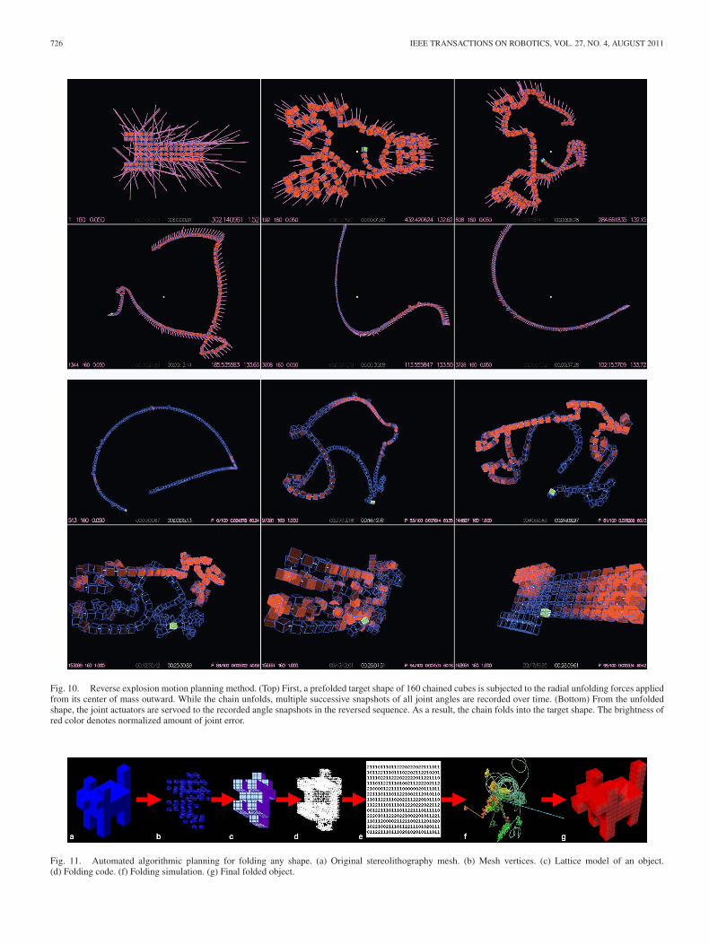
Our workflow starts with an algorithmic representation ofa shape. This is then evaluated over a lattice, to construct aHamiltonian path, which is then processed into the code forthe string (see Fig. 11). We have fabricated small-scale proofsof concept, and are experimenting with kinematics models thatare a subset of that which is described in the proof in order to
Fig. 6. Interconnection patterning: 1-D to 2-D (top) and 1-D to 3-D (bottom), aworking model with magnets. The top example of a vertex-connected 1-D to 2-Dstring is shown for clarity. The direct 1-D to 2-D analog for our implementationof the 1-D to 3-D string would be shown but with alternating (left and right)faces permanently connected and the hinges occurring across the diagonals sothat the device comes out of plane and into the third dimension during thefolding process (similar to 2-D configuration of Rubik’s Snake toy). The leftbottom diagram shows the physically discrete units of our 3-D implementationas alternating red and green.
rapidly adopt known mechanisms (novel motors, bearings, orconnectors are not required to implement this strategy). Large-scale fabrication processes are simulated (see supplementarymovies 1–3), and a key aspect of the simulations is that eachunit in the simulation solves for a local solution at each timestep—the global solution is a product of the aggregated localresults of the programs of each unit. This program can be assimple as a string of instructions for each single DOF revolutejoint, such as “turn or go straight,” in the case of 2-D, or “turnclockwise, counterclockwise, or go straight,” in the case of 3-D.
V. EXPERIMENT AND SIMULATION
In order to validate the applicability of these techniques forengineered systems, we implemented examples of robotic pro-grammable universally foldable strings (moteins) in simulationand built short robotic strings in order to verify the mechanicsused in the simulations. Two scales of the cubic lattice-basedmotein (C-motein) will be discussed: here—a centi-C-motein(cC-motein) with about a 1 cm diameter unit size and a mole-cuboid C-motein (MC-motein) with about a 10 cm diameter unitsize. These two examples possess the same fundamental kine-matics (the difference between them is that the latter is aboutten times larger than the former).
The larger physical MC-motein (see Fig. 8 and supplemen-tary movie 5) was built to quickly test these ideas in a fullyactuated test-bed. Each unit is constructed similarly to a mole-cube unit [17], with a single bearing and servo motor housed ina printed thermoplastic (Dimension Elite) chassis. The smallerphysical cC-motein (see Fig. 6 and supplementary movie 9)shown here was built as a passive kinematic test-bed to studyconnectivity and reconfigurability characteristics. These wereprinted as complete strings in acrylic (3D Systems InVision si)with magnets pressed in afterward. We expect that a fully ac-tuated physical cC-motein is realizable, given the simplicity ofthese units.

CHEUNG et al.: PROGRAMMABLE ASSEMBLY WITH UNIVERSALLY FOLDABLE STRINGS (MOTEINS) 723
Fig. 7. Kinematic scaling with subloops, showing the ability to perform translation (top) and rotation (bottom) routines with closed kinematic loops of theuniversally foldable chain.
Fig. 8. ODE simulation (green) and actual movement of eight-module string, showing the ability of chains of the module geometry to perform parallel folding.
Both C-moteins presented here, as well as all simulations,employ a single revolute joint as the single DOF per unit. TheMC-motein robot and all simulations employ a servo motor toactuate this joint. Observed and simulated mass density is about0.4 gm/cm3 for both C-moteins.
Our goal in this section is to address practical implications,such as motion-planning schemes (i.e., parallel versus serialfolding) and their impact on the amount of time that it wouldtake for this type of robot to perform (re)configuration.
A. Design
We chose the most basic kinematic design that provides con-tinuous motion between all necessary final configuration states,for a string system that closely packs on a cubic lattice. Eachmodule in this device would have to be able to position its fol-lowing module at any one of three positions (shown by the bluearrows in Fig. 5) relative to its previous module (shown by thewhite arrow in Fig. 5, considering rotational symmetry). Thisis accomplished with a single rotational joint about a longestinterior chord connecting two vertices of the cube (see the greenline in Fig. 5).
An even bisection with a plane that is orthogonal to thisaxis produces the regular hexagonal bisection of the cube (theresulting cross-sectional face is a regular hexagon). When theseare arranged as a string with rigid bonds between hemicubesarranged such that each is a mirror image of its neighbor (acrossthe bonding plane shared with the neighbor cube), we obtain themodule design shown on the right-hand side of Fig. 5.
While this design can form any shape (fits with the construc-tive proof of universal foldability), it meets only a subset ofthe requirements to navigate all folding motions with continu-ous motion. We are providing this example for simplicity andin order to suggest that the fundamental algorithms for fold-ing schema presented here may be applied to chained versionsof most existing reconfigurable robotic systems [17], [18] withuseful results. The rest of this paper addresses this simplifiedmodel, in both simulation and hardware. This hexagonally bi-sected cube geometry was first realized in the field of reconfig-urable robotics with the molecube system [17], with its cubicmodules whose connections are reconfigurable, as opposed tobeing constrained as a chain. The example that we present hereis also somewhat similar to Rubik’s Snake toy (which can beapproximated by other robots, such as Atron) but with modulesthat closely pack on a cubic lattice and with a corresponding
2(ArcTan(1/(√
2 − (1/√
2)))) ≈ 109.4713◦ (0a)
dihedral angle between bearing faces (instead of the π/2 dihedralangle of Rubik’s Snake module).
Since this architecture includes an integral backbone, data andpower transfer can simply run through a continuous conductorbus (reliable electrical collectors/slip rings are trivial to integrateif the ability to perform large numbers of net twists is desired).The outer surfaces of the chains are free to be left to carryfunctions other than reconfiguration, such as carrying payloads.
These unnecessary but potential interconnections betweenspatially adjacent units that are far apart along the stringmay still be desired, for instance, to parallelize power and

724 IEEE TRANSACTIONS ON ROBOTICS, VOL. 27, NO. 4, AUGUST 2011
data transfer. Corresponding connector plates require onlytwofold rotation symmetry, with a very simple layout. Thisis perhaps easiest to visualize in the 2-D example at the topof Fig. 6. If each unit in the square lattice has male (−)connector plates (blue in Fig. 6) on the down-string side andfemale (+) connector plates (orange in Fig. 6) on the up-stringside, then the string will always pack with proper pairingof connector plates. This follows from the path constructionalgorithm, as a single-square macropixel mates properly onall four sides with another macropixel, and the connectionpatterning of the macropixel surface remains intact throughoutthe path construction operation (some faces are “replaced”with permanent connections in order to create the string and,therefore, become irrelevant to the interconnection scheme).
With our implementation in 3-D, each unit in the cubic latticehas four potential connector faces, since the up-string and down-string faces are permanently attached to other units. These fourfaces may be grouped into two groups of two, as divided bythe hexagonal bisection line previously described. If we desig-nate that the group that is connected down-string has male (−)connector plates and the group that is connected up-string hasfemale (+) connector plates, for all units (as shown in Fig. 8),then all valid configurations will result in correctly paired con-nector plates. As with the 2-D example, a single 3-D macrovoxelmates properly on all six sides with other macrovoxels, and theconnection patterning of the macrovoxel surface remains intactthroughout the path construction operations.
Fig. 7 (and supplemental movie 9) shows examples of larger-than-unit scale translation and rotation routines that can be per-formed by closed subloops of these string robots. As such, onemight imagine suites of locomotion and/or manipulation robotsthat can reconfigure between functions—with a key attribute thatthey are all composed of strings of simple and identical units.
B. Implementation
To summarize the design, we chose a string system that packson a cubic lattice, with one rotational DOF per module. Thesingle corresponding bearing/hinge and actuator per module hasthree states: {0, 2π/3,−2π/3}. Therefore, the only informationthat has to be sent to each unit is “stay straight,” “turn counter-clockwise,” or “turn clockwise,” for each module, together withan addressing scheme.
To obtain a better sense of the kinematic constraints of thedesign when a number of units are connected in a string, webuilt a number of prototypes and found the system to be quiteflexible. For instance, the bearing gap seen in Fig. 5 may besignificantly enlarged (along the rotation axis) to create a sparsestructure, as the symmetry of the folding is such that in thefinal configuration the main body of the modules will occupycorresponding corners of the cubes on the packing lattice, suchthat incident faces of the modules still line up (for structuraland/or latching purposes).
The final design (shown in Fig. 8 and supplemental movies 4and 5) utilized the compact integration of the dynamixel AX-12servo motor and ring gear of the molecube design [17]. Powerand data were carried on the stock dynamixel three-wire bus.
The packing lattice for this string has a 27-in3 unit. Since thisdesign desirably gears down the AX-12 units by a factor of3, and the closed loop servo mode of the AX-12 unit does notallow full rotation, reconfiguration commands to each modulewere accomplished by first implementing a timed directionalfree run, followed by a switch to servo mode for precisepositioning of the goal state. The geared-down drive systemsprovide less than one-tenth of a degree of resolution; therefore,we find it unnecessary to include an active connection interfaceto connect units that are far apart along the string but spatiallyadjacent in their final configuration.
Open dynamics engine (ODE) [19] was used for the sim-ulations, with values for dimensions, mass, and motor torquematched to the compact robots in Fig. 8. Continuing work ad-dresses smaller (∼100 μm) and larger (∼1 m) folding systemson various lattice geometries, but here, we will primarily discussmass, force, and dimensional scales that are conventional in thefield of reconfigurable robotics.
C. Folding Simulation
Our goal with the simulations is to broadly investigate thecharacteristics of these systems when they have large numbersof units. We describe initial experiments with folding using threemotion-planning techniques here—naıve parallel folding, re-verse explosion planning, and the probabilistic roadmap method(PRM).
1) Parallel Folding: Simple parallel folding, where the fold-ing instruction is distributed to all modules and they areallowed to actuate simultaneously with even power distri-bution, can work well but is quite sensitive to the nature ofthe initially chosen folding path. Primarily due to inertialfactors at these scales, the effect that we observe in thesimulations is delayed folding in the middle or anchoredend of the string, as the modules toward the end(s) com-plete their configurations first. These precompleted endsmust fit together easily in order for this strategy to beefficient and not require refolding.
2) Reverse Explosion: In experimenting with various refold-ing heuristics, we observe that it may be easier to unfoldthan to fold. This reverse explosion method starts with thetarget configuration in simulation and applies repulsiveforces to unfold the chain, while recording the joint an-gles at predefined time steps. The folding forces includeoutward forces to all modules in the direction originatingfrom the center of mass of the entire ensemble, as well asa repelling force between nonadjacent modules during theunfolding. Therefore, the modules not only explode fromthe center but maintain distance from nearby modules aswell. During this part of the process, the motors on thejoints are turned OFF and the joints themselves merely en-force the passive between-module kinematic constraints.The resulting motion plan is to servo to the list of recordedangles in reverse chronological order. Each recorded set ofangles acts as a target to which we servo until the largestangle error is less than some given threshold. Fig. 9 givespseudocode for this reverse explosion algorithm.

CHEUNG et al.: PROGRAMMABLE ASSEMBLY WITH UNIVERSALLY FOLDABLE STRINGS (MOTEINS) 725
Fig. 9. Pseudocode for reverse explosion algorithm.
We compute the radial force as a vector in the outward di-rection or a module’s position minus the center of mass of theensemble
ei = λpi − c
d(1a)
where λ is the radial force gain, pi is the module position of theith module, d is the diameter of the configuration, and c is thecenter of mass
c =n∑
i=0
pi
n. (1b)
The radial force increases with distance from the center of mass,causing modules on the outside to explode faster than ones in theinside. This also lowers the chance of collisions by encouragingmodules to be maximally distant from each other. The repellingforce is computed as a 1/d2 force between nonadjacent modules
ri =n∑
j=0
γ
(pj − pi)2 (1c)
where γ is the repulsion force gain. In order to speed up thesimulation, a maximum unit distance for application of repulsionforces may be applied.
Results from this reverse explosion method are shown inFig. 10 and movies 6 and 10 in the supplementary materials.Fig. 10 shows a 160-module chain and a configuration shapeof a wrench. Relevant parameters for these simulations are λ =0.1, γ = 1, and maximum squared error threshold of 0.15. Thecompanion video shows the algorithm that runs on a number ofcanonical geometric shapes.
The naıve parallel folding could be viewed as a form of thisreverse explosion method but with zero intermediary steps. In-versely, the reverse explosion method could be viewed as acomposition of naıve folding steps. As such, the number ofrequired intermediary steps for a successful reverse explosion
method is also very sensitive to the nature of the initially chosenfolding path.
D. Folding Analysis
Noting a large scope of serial, parallel, or other heuristicmotion-planning methods that can be applied to our foldingschema, we have analytically estimated lower and upper boundson the amount of time that the folding process will take to com-plete, assuming significant inertial effects, and critical dampingof the string’s motion (see Fig. 11).
Our estimation for the upper bound on folding time assumesthat the largest possible inertia term for the nth module will resultfrom the 0th through (n−1)th modules that exist in a straight-chain configuration. For parallel folding, this upper bound onthe time to fold is equal to the time to fold of the module atthe middle or anchored end of the string (2c), shown below.For serial folding, this upper bound on the time to fold is thesum of all tn , shown below in (2d). In the following equations,α represents the angular acceleration, τ represents the torque,which is assumed to be a fixed scalar, I represents the moment ofinertia, and δ represents the one unit distance between modules.
(For a string of length n units)
2π
3=
12αnt2n ; αn =
τ
In(2a)
(time to fold as a function of distance, torque, and inertia)
In =n∑
i=1
m(iδ)2 ; |tn | =
√4π
∑ni=1 m(iδ)2
3τ(2b)
(maximum inertial term; “least folded” chain configuration)
|tn | =√
2π
3
√nm(2n2 + 3n + 1)δ2
τ; tparallel = O(n3/2)
(2c)(maximum single fold time, for parallel folding)
tserial ≈∫ n
0ki
32 di = O(n
52 ) (2d)
(sum of fold times for serial folding).Our estimation for the lower bound on fold time assumes
that the smallest possible inertia term for the nth module willresult from the 0th through (n−1)th modules existing in a foldedconfiguration whose center of mass is a distance of one unit fromthe center of mass of this nth module. Similar to the upper boundcalculation, for parallel folding, this lower bound on the timeto fold is equal to the time to fold of the module at the middleor anchored end of the string in (3b), shown below; for serialfolding, this lower bound on the time to fold is the sum of alltn , as in (3c), shown below.
(For a string of length n units)
In = (nm)δ2 ; |tn | =
√4π(nm)δ2
3τ(3a)
(maximum inertial term; “most folded” chain configuration)
|tn | = 2√
π
3
√(nm)δ2
τ; tparallel = Ω(n1/2) (3b)
726 IEEE TRANSACTIONS ON ROBOTICS, VOL. 27, NO. 4, AUGUST 2011
Fig. 10. Reverse explosion motion planning method. (Top) First, a prefolded target shape of 160 chained cubes is subjected to the radial unfolding forces appliedfrom its center of mass outward. While the chain unfolds, multiple successive snapshots of all joint angles are recorded over time. (Bottom) From the unfoldedshape, the joint actuators are servoed to the recorded angle snapshots in the reversed sequence. As a result, the chain folds into the target shape. The brightness ofred color denotes normalized amount of joint error.
Fig. 11. Automated algorithmic planning for folding any shape. (a) Original stereolithography mesh. (b) Mesh vertices. (c) Lattice model of an object.(d) Folding code. (f) Folding simulation. (g) Final folded object.

CHEUNG et al.: PROGRAMMABLE ASSEMBLY WITH UNIVERSALLY FOLDABLE STRINGS (MOTEINS) 727
(maximum single fold time, for parallel folding)
tserial ≈∫ n
0ki1/2di = Ω(n3/2) (3c)
(sum of fold times, for serial folding).These results show that for strings with large numbers of
units, parallel folding schemes can be much quicker to fold thanserial folding schemes, which is not surprising. The slowest n-unit long serial folding scheme will take a factor of n2 more timeto fold than the fastest parallel folding scheme. However, theseresults also suggest that the least time-efficient parallel foldingschemes, in terms of time needed to fold, can be approximatelymatched by the most time-efficient serial folding schemes dueto inertial effects. Therefore, we may consider serial foldingstrategies as viable even for long strings especially when otheradvantages are taken into account, such as managing the powerrequirements of the system or enabling the folded modules tobe passive, while folded by a robot [5], [6], [20].
E. Reconfiguration Simulation
So far, we have implied methods of folding between twoconfigurations—by unfolding completely from the first config-uration before folding into the second configuration. We wouldprefer to investigate more efficient paths between any two con-figurations. In this section, we briefly show the applicabilityof existing robotic motion-planning strategies to folding digi-tal chains, by demonstrating the use of a PRM. This methodof finding motions between configurations, developed for theprotein folding problem, has been shown to be reasonably effi-cient, and has already seen applications in a number of roboticsystems [21].
The PRM initially samples configuration space for collision-free configurations. We employed simple random sampling inthis example, but more sophisticated sampling algorithms areavailable. These initial configurations serve as the initial nodesin a roadmap graph. Nearby pairs of nodes are then chosen andapproved to be collision free by running a simple local planneruntil a connected graph is formed. Finally, a path from a startand end configuration is found in the roadmap graph.
There are some particulars, which are unique to digital chains,that we need to address. First, a configuration for a chain is avector of n joint angles. We could choose configurations witheach joint’s continuous range of motion (−2π/3 to 2π/3), butwe find that using discrete positions is preferable. All configu-rations are first filtered using a self-intersection algorithm—forcontinuous positions, this can employ a high-speed collisiondetector, such as the Software Library for Interference Detec-tion (SOLID) [22]. However, when the initial configurationsare restricted to discrete positions, collision detection can beperformed very quickly, since each position can be representedefficiently, and examining the validity of a configuration simplyrequires stepping around a discrete lattice, instead of summing along list of vectors. Further, simple patterns and algorithms canbe used to prune invalid configurations (e.g., “if your directionssay to make four consecutive turns in the same direction on a
Manhattan grid, then you have bad directions”). This can beefficiently performed in an O(n × n × n) matrix.
Neighbors in the configuration space are found by consid-ering configurations in distance order, to see whether they arereachable using simple linear interpolation local path planning.We use the binary search approach to decide whether interme-diate linearly interpolated configurations are self-intersecting.The distance metric between configurations can simply be theL2 norm or the sum of the squared angle errors between config-urations.
We use Dijkstra’s algorithm for shortest path determination,which starts by marking the final (goal) configuration node asvisited and with zero distance. Then, iteratively, neighbors ofnewly visited nodes are marked, and their distances to the endconfiguration are updated as a function of their local distanceto their neighbors and their neighbors’ best estimate to the endconfiguration. The smoothing algorithm to shorten paths foundusing Dijkstra’s algorithm is very straightforward and previ-ously reported [23]. Random configuration pairs from the short-est path are chosen, and intervening configurations are removedif there is a locally plan-able path between them.
In summary, with discrete configurations as way points inthe PRM, the path can be described efficiently as discrete dif-ferences between configurations. In the binary case, the differ-ence between configurations can be described as a Hammingdistance [24]. Path fitness can be measured in terms of the ham-ming difference between the start and end target configurationsand the sum of the hamming distances between configurationsalong the path.
The results are quite promising; see supplementary movie 11,for a simulation of reconfiguration of a 140-module digital chainbetween the words hello and world and a few other shapes.
VI. DISCUSSION
We see three main topics for future work with this type offolding string: initial selection of a space-filling curve from thespace of curves that are possible for a given shape, further workon motion planning, and applications.
The selection of a most suitable spanning tree for a givenshape remains an open question. There are many strategies todevelop this initial pre-subdivided tree from which the final 3-Dspace-filling curve is generated. We expect that specific answerswill derive from functional (e.g., structural) requirements. Somestrategies may derive from the ability to tune anisotropic bulkstructural properties. It is relatively simple to achieve high dif-ferential strength between the permanent (with one rotationalDOF) connections between units along the string and the otherspatially adjacent connections (or lack of mechanical connec-tion). Other strategies may relate to reconfiguration.
For example, it may be desirable to perform the least possibleturning in the path or as much as possible. The former may beachieved by following the perimeter of a figure and spiraling inas necessary, only branching to fill areas of the figure that cannotbe reached with a single spiral. This is suitable for serial foldingschemes. One method to achieve relatively many turns involvesperforming a distance transform to the edge of a voxellated

728 IEEE TRANSACTIONS ON ROBOTICS, VOL. 27, NO. 4, AUGUST 2011
figure, then constructively generating the spanning graph bystarting with the voxels with the highest values (the most in-terior voxels), and always performing the constructive additionof the remaining voxels to neighbors with lower values (moreexterior). Thus, the spanning graph has a medial axis back-bone with many spines leading to the extremities so that thefolding is most accordion like. This kind of structure has ad-vantages for parallel folding schemes. Such consideration ofactuation sequence—and the implication that one can use in-formation about future desired configurations in order to planearlier configurations—leads us back to the topic of motionplanning.
In this paper, we have just touched on the topic of motionplanning, in order to show the viability of the design. Prior workin motion planning has shown many techniques that could beapplied to universally foldable string robots, which explore thespace of folding strategies for reconfigurable systems. Manymethods applied to the motion-planning problem for latticerobots, such as subdividing with similarity metrics [25] andsimulated annealing [26], can be extended to apply to chainedconfigurations. Perhaps, the most clearly applicable methodsare derived from PRMs developed for the protein folding prob-lem, and which already have been specifically applied to roboticfolding systems [27]. It is worth noting that the applications ofthese types of motion planning methods toward closed kine-matic loop mechanisms [28], [29] also point toward the widerange of potential functional applications of universally foldablestring robots beyond shape making.
We know that geometry is sometimes regarded to be a corner-stone of many functional (i.e., biological) systems, and this mayprovide an avenue toward programming various types of mech-anisms, through geometric arrangement of functional units. Thefolding system as described here could have functionality su-perimposed on different pixels or voxels, and sequencing wouldallow the positioning of those functional components at any de-sired location in the global 3-D structure. Furthermore, sincethe string can be folded between any two configurations, thisdirectly implies a route to reconfigurable matter, where a sin-gle string with simple actuators could fold from any one con-figuration to any other in order to serve different and com-plex mechanical (i.e., locomotion) and/or computational [30]functions.
VII. CONCLUSION
We have shown a technique to design universally foldablestring robots, with proof of existence of continuous motion forself-assembly and self-reconfiguration. These results may fur-ther the revolution from analog to digital materials and fabrica-tion processes, through computational tools to employ biologi-cally inspired assembly systems and by enabling low cost andreversible de novo systems. We know how to make communica-tion and computation systems that scale well enough to operateas designed, with Avogadran numbers of units. This is largelyachieved through error reduction and correction strategies thatmake good bets on the physics of the system. Biology showsthat these goals can be satisfied in a system to fabricate things,
or “programming matter,” through the encoding of structuraland functional information in 1-D, with a small and discrete setof parts. Furthermore, there is some evidence to indicate thatcomplex biological structures can result from the aggregatedbehavior of large quantities of discrete components with eversimpler physical models [31].
Reconfigurable robotics has come a long way and has along and interesting road ahead, that is, toward successful pro-grammed assembly of very large and complex structures [32];we hope that the techniques presented here will be useful as amethod of programmatically making vast libraries of parts fromany very basic set of mechanisms. In the shorter term, we hopethat with these techniques and the simplifications afforded byhaving an integral backbone and very low DOF and states perunit, many existing reconfigurable robotics benchmarks mightbe surpassed—such as the number of active modules in a singlesystem, actuated module size (smallness), and robustness of self-reconfiguration. A crux of many existing reconfigurable roboticssystems is the reconfigurable communications and power con-nections (the ability for modules to attach and detach from eachother)—these are difficult and expensive to build; our robots(moteins) are not reliant on such mechanisms.
Clearly, the most exciting and most open problem is that of ap-plications. This technique of algorithmic generation of programsfor self-folding matter presents a new method of working towardtruly digital artificial fabrication systems. The old question thatwe strive to answer is how we can effectively and efficiently getfrom a description of an object to the functional object itself,with an eye toward material life cycles. This study suggests amanner to describe objects by their generative programs so thatthe description itself is also the very digital information neededto fabricate the object.
Ongoing work is aimed toward addressing folding strategies,including reconfiguration motion planning and the advantagesof different geometric properties of the initial lattice used. 2-Dand 3-D patchworks of polygons and polyhedra allow for a finalresult with tuned sparseness and correspondingly faster foldingtimes (due to decreased string length). Other relevant ongoingwork includes analysis of bulk properties of these kinds of as-semblies [33], development of actuators specifically geared to-ward this application [34], and cellular computing based modelsfor executing programs across these kinds of modules (such as tocompute reconfiguration strategy) with extremely low per-unitcost [35], [36].
OPEN SOURCE CODE
Programs and open source code that execute the algorithmsdescribed in this paper are available for research and educationaluse from the authors.
ACKNOWLEDGMENT
The authors would like to thank the Center for Bits and Atoms,N. Gershenfeld, and J. Jacobson for support and critical discus-sions, V. Zykov for technical advice with device engineering,and the fab lab network for contextual grounding.

CHEUNG et al.: PROGRAMMABLE ASSEMBLY WITH UNIVERSALLY FOLDABLE STRINGS (MOTEINS) 729
REFERENCES
[1] B. Lewin, Genes IV: Oxford: Oxford Univ. Press, 1990.[2] N. Brener, F. B. Amar, and P. Bidaud, “Designing modular lattice systems
with chiral space groups,” Int. J. Robot. Res., vol. 27, no. 3, pp. 279–297,2008.
[3] M. Yim, W. Shen, B. Salemi, D. Rus, M. Moll, H. Lipson, E. Klavins,and G. S. Chirikjian, “Modular self reconfigurable robot systems [grandchallenges of robotics],” IEEE Robot. Autom. Mag., vol. 14, no. 1, pp. 43–52, Mar. 2007.
[4] G. S. Chirikjian, “Kinematics of a metamorphic robotic system,” in Proc.IEEE Int. Conf. Robot. Automat., San Diego, CA, May 1994, pp. 449–455.
[5] D. J. Balkcom and M. T. Mason, “Robotic origami folding,” Int. J. Robot.Res., vol. 27, no. 5, pp. 613–627, 2008.
[6] L. Lu and S. Akella, “Folding cartons with fixtures: A motion-planningapproach,” IEEE Trans. Robot. Automat., vol. 16, no. 4, pp. 346–356,Aug. 2000.
[7] E. Hawkes, B. An, N. M. Benbernou, H. Tanaka, S. Kim, E. D. Demaine,D. Rus, and R. J. Wood, “Programmable matter by folding,” Proc. Nat.Acad. Sci., vol. 107, no. 28, pp. 12441–12445, 2010.
[8] G. Peano, “Sur une courbe, qui remplit toute une aire plane,” Math. Ann.,vol. 36, no. 1, pp. 157–160, 1890.
[9] D. Hilbert, “Ueber die stetige Abbildung einer Line auf ein Flachenstuck,”Math. Ann., vol. 38, pp. 459–460, 1891.
[10] E. D. Demaine, M. L. Demaine, D. Eppstein, G. N. Frederickson, andE. Friedman, “Hinged dissection of polyominoes and polyforms,” Com-put. Geom.: Theory Appl., vol. 31, no. 3, pp. 237–262, 2005.
[11] S. Griffith, “Growing machines,” Ph.D. dissertation, Mass. Inst. Tech.,Cambridge, MA, 2004.
[12] E. D. Demaine, M. L. Demaine, J. F. Lindy, and D. L. Souvaine, “Hingeddissection of polypolyhedra,” in Proc. 9th Workshop Algorithms DataStructures, 2005, vol. 3608, pp. 205–217.
[13] R. Connelly, E. D. Demaine, M. L. Demaine, A. Ribo, and G. Rote,“Locked and unlocked chains of planar shapes,” in Proc. 22nd Annu.ACM Symp. Computat. Geom., 2006, pp. 61–70.
[14] A. Itai, C. H. Papadimitriou, and J. L. Szwarcfiter, “Hamilton paths in gridgraphs,” SIAM J. Comput., vol. 11, pp. 676–686, 1982.
[15] S. H. Poon, “On Unfolding 3D Lattice Polygons and 2D OrthogonalTrees,” in Proc. 14th Annu. Int. Comput. Combinatorics Conf., 2008,pp. 374–384.
[16] J. H. Chen and N. C. Seeman, “Synthesis from DNA of a molecule withthe connectivity of a cube,” Nature, vol. 350, pp. 631–633, 1991.
[17] V. Zykov, E. Mytilinaios, B. Adams, and H. Lipson, “Robotics: Selfreproducing machines,” Nature, vol. 435, pp. 163–164, 2005.
[18] G. M. Whitesides and M. Boncheva, “Beyond molecules: Self-assemblyof mesoscopic and macroscopic components,” Proc. Nat. Acad. Sci. USA,vol. 99, no. 8, pp. 4769–4774, 2002.
[19] Open Dynamics Engine (ODE) (2004). [Online]. Available: http://www.ode.org/ode.html
[20] P. J. White, C. E. Thorne, and M. Yim, “Right angle tetrahedron chainexternally-actuated testbed (RATChET): A shape-changing system,” inProc. Int. Design Eng. Tech. Conf. Comput. Inform. in Eng. Conf.IDETC/CIE, 2009, vol. 7, pp. 807–817.
[21] C. J. Chiang and G. S. Chirikjian, “Modular robot planning using similaritymetrics,” Auton. Robots, vol. 10, pp. 91–106, 2001.
[22] Software Library for Interference Detection (SOLID) (2004). [Online].Available at http://www.win.tue.nl/∼gino/solid/
[23] N. M. Amato and G. Song, “Using motion planning to study proteinfolding pathways,” J. Comput. Biol., vol. 9, no. 2, pp. 149–168, Apr.2002.
[24] R. W. Hamming, “Error detecting and error correcting codes,” Bell Syst.Techn. J., vol. 29, no. 2, pp. 147–160, 1950.
[25] A. Pamecha, I. Ebert-Uphoff, and G. S. Chirikjian, “Useful metrics formodular robot motion planning,” IEEE Trans. Robot. Automat., vol. 13,no. 4, pp. 531–545, Aug. 1997.
[26] S. Kirkpatrick, C. D. Gelatt, and M. P. Vecchi, “Optimization by simulatedannealing,” Sci. New Series, vol. 220, no. 4598, pp. 671–680, 1983.
[27] G. Song and N. M. Amato, “A motion-planning approach to folding: Frompaper craft to protein folding,” IEEE Trans. Robot. Automat., vol. 20, no. 1,pp. 60–71, Feb. 2004.
[28] L. Kavraki, P. Svestka, J. C. Latombe, and M. Overmars, “Probabilisticroadmaps for path planning in high dimensional configuration spaces,”IEEE Trans. Robot. Automat., vol. 12, no. 4, pp. 566–580, Aug. 1996.
[29] J. Cortes, T. Simeon, and J. P. Laumond, “A random loop generator forplanning the motions of closed kinematic chains using PRM methods,” inProc. IEEE Int. Conf. Robot. Automat., 2002, pp. 2141–2146.
[30] M. Boncheva, D. H. Gracias, H. O. Jacobs, and G. M. Whitesides,“Biomimetic self-assembly of a functional asymmetrical electronic de-vice,” Proc. Nat. Acad. Sci., vol. 99, no. 8, pp. 4937–4940, 2002.
[31] S. Sun, P. D. Thomas, and K. A. Dill, “A simple protein folding algorithmusing a binary code and secondary structure constraints,” Protein Eng.,vol. 8, no. 8, pp. 769–778, 1995.
[32] G. M. Whitesides and B. Grzybowski, “Self-assembly at all scales,” Sci-ence, vol. 295, no. 5564, pp. 2418–2421, 2002.
[33] P. J. White, S. Revzen, C. E. Thorne, and M. Yim, “A general stiffnessmodel for programmable matter and modular robotic structures,” Robot-ica, vol. 29, pp. 103–121, 2011.
[34] A. Knaian, “Electropermanent magnetic connectors and actuators: De-vices and their application in programmable matter,” Ph.D. dissertation,Mass. Inst. Technol., Cambridge, MA, 2010.
[35] T. Fukuda, Y. Kawauchi, and F. Hara, “Dynamic distributed knowledgesystem in self-organizing robotic systems; CEBOT,” in Proc. IEEE Conf.Robot. Automat., 1991, pp. 1616–1621.
[36] N. Gershenfeld, D. Dalrymple, K. Chen, A. Knaian, R. Green, E. D.Demaine, S. Greenwald, and P. Schmidt-Nielsen, “Reconfigurable asyn-chronous logic automata,” in Proc. 37th Annu. ACM SIGACT-SIGPLANSymp. Principles Programming Languages, 2010, vol. 45, no. 1, pp. 1–6.
Authors’ photographs and biographies not available at the time of publication.