66 Centuries of Measurement
73
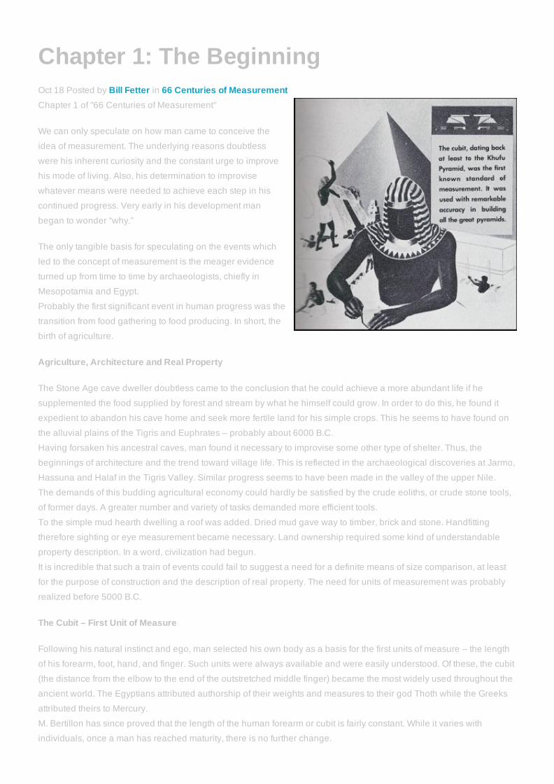
Chapter 1: The Beginning Oct 18 Posted by Bill Fetter in 66 Centuries of Measurement Chapter 1 of "66 Centuries of Measurement" We can only speculate on how man came to conceive the idea of measurement. The underlying reasons doubtless were his inherent curiosity and the constant urge to improve his mode of living. Also, his determination to improvise whatever means were needed to achieve each step in his continued progress. Very early in his development man began to wonder “why.” The only tangible basis for speculating on the events which led to the concept of measurement is the meager evidence turned up from time to time by archaeologists, chiefly in Mesopotamia and Egypt. Probably the first significant event in human progress was the transition from food gathering to food producing. In short, the birth of agriculture. Agriculture, Architecture and Real Property The Stone Age cave dweller doubtless came to the conclusion that he could achieve a more abundant life if he supplemented the food supplied by forest and stream by what he himself could grow. In order to do this, he found it expedient to abandon his cave home and seek more fertile land for his simple crops. This he seems to have found on the alluvial plains of the Tigris and Euphrates – probably about 6000 B.C. Having forsaken his ancestral caves, man found it necessary to improvise some other type of shelter. Thus, the beginnings of architecture and the trend toward village life. This is reflected in the archaeological discoveries at Jarmo, Hassuna and Halaf in the Tigris Valley. Similar progress seems to have been made in the valley of the upper Nile. The demands of this budding agricultural economy could hardly be satisfied by the crude eoliths, or crude stone tools, of former days. A greater number and variety of tasks demanded more efficient tools. To the simple mud hearth dwelling a roof was added. Dried mud gave way to timber, brick and stone. Handfitting therefore sighting or eye measurement became necessary. Land ownership required some kind of understandable property description. In a word, civilization had begun. It is incredible that such a train of events could fail to suggest a need for a definite means of size comparison, at least for the purpose of construction and the description of real property. The need for units of measurement was probably realized before 5000 B.C. The Cubit – First Unit of Measure Following his natural instinct and ego, man selected his own body as a basis for the first units of measure – the length of his forearm, foot, hand, and finger. Such units were always available and were easily understood. Of these, the cubit (the distance from the elbow to the end of the outstretched middle finger) became the most widely used throughout the ancient world. The Egyptians attributed authorship of their weights and measures to their god Thoth while the Greeks attributed theirs to Mercury. M. Bertillon has since proved that the length of the human forearm or cubit is fairly constant. While it varies with individuals, once a man has reached maturity, there is no further change.
description
Istorija merenja
Transcript of 66 Centuries of Measurement
Chapter 1: The BeginningOct 18 Posted by Bill Fetter in 66 Centuries of MeasurementChapter 1 of "66 Centuries of Measurement"
We can only speculate on how man came to conceive the
idea of measurement. The underlying reasons doubtless
were his inherent curiosity and the constant urge to improve
his mode of living. Also, his determination to improvise
whatever means were needed to achieve each step in his
continued progress. Very early in his development man
began to wonder “why.”
The only tangible basis for speculating on the events which
led to the concept of measurement is the meager evidence
turned up from time to time by archaeologists, chiefly in
Mesopotamia and Egypt.
Probably the first significant event in human progress was the
transition from food gathering to food producing. In short, the
birth of agriculture.
Agriculture, Architecture and Real Property
The Stone Age cave dweller doubtless came to the conclusion that he could achieve a more abundant life if he
supplemented the food supplied by forest and stream by what he himself could grow. In order to do this, he found it
expedient to abandon his cave home and seek more fertile land for his simple crops. This he seems to have found on
the alluvial plains of the Tigris and Euphrates – probably about 6000 B.C.
Having forsaken his ancestral caves, man found it necessary to improvise some other type of shelter. Thus, the
beginnings of architecture and the trend toward village life. This is reflected in the archaeological discoveries at Jarmo,
Hassuna and Halaf in the Tigris Valley. Similar progress seems to have been made in the valley of the upper Nile.
The demands of this budding agricultural economy could hardly be satisfied by the crude eoliths, or crude stone tools,
of former days. A greater number and variety of tasks demanded more efficient tools.
To the simple mud hearth dwelling a roof was added. Dried mud gave way to timber, brick and stone. Handfitting
therefore sighting or eye measurement became necessary. Land ownership required some kind of understandable
property description. In a word, civilization had begun.
It is incredible that such a train of events could fail to suggest a need for a definite means of size comparison, at least
for the purpose of construction and the description of real property. The need for units of measurement was probably
realized before 5000 B.C.
The Cubit – First Unit of Measure
Following his natural instinct and ego, man selected his own body as a basis for the first units of measure – the length
of his forearm, foot, hand, and finger. Such units were always available and were easily understood. Of these, the cubit
(the distance from the elbow to the end of the outstretched middle finger) became the most widely used throughout the
ancient world. The Egyptians attributed authorship of their weights and measures to their god Thoth while the Greeks
attributed theirs to Mercury.
M. Bertillon has since proved that the length of the human forearm or cubit is fairly constant. While it varies with
individuals, once a man has reached maturity, there is no further change.

The earliest authentic unit of length is the Royal Egyptian Cubit, known to have been in use at the time the Khufu
Pyramid was constructed (2750 B.C.), and mentioned in connection with the building of Noah's Ark.
Careful measurement of the Khufu Pyramid of Gizeh which measures about 756 feet on each side and is 481 feet high,
shows a mean error in the length of the sides of only 0.6 inch and an error in angle from a perfect square of only 12
seconds.
There is also good reason to believe a cubit was the unit used in Babylonia and by the ancient Jews.
The cubit was inherited by the Greeks and the Romans, but, from archaeological evidence, none of these cubits
agreed in actual length. The Royal Egyptian Cubit seems to have been approximately equal to 20.62 of our inches.
The Greek cubit was 2.38 inches shorter. The area of a square on the Greek Olympic Cubit is equal to that of a circle
having a diameter of one Royal Egyptian Cubit. If this is a coincidence, it is a very interesting one.
As far as is known, the Greeks were the first to subdivide the cubit. They broke it down into two spans, six palms or
twentyfour digits. The Romans in turn took the Greek Olympic Cubit, but subdivided it according to their own ideas into
twelve thumb nail breadths or unciae.
First Legal Code
There is what remains of a sunbaked clay tablet in the museum at Istanbul which was written by a scribe in cuneiform
about 2050 B.C. It is the oldest written law code known to man, antedating that of Hammurabi by some 300 years.
These laws promulgated by the Sumerian King UrNammu contain a reference to honest weights and measures.
Britain's Stonehenge
Stonehenge, on the Salisbury Plain, Wiltshire, one of the mysteries of British antiquity, is interesting for a number of
reasons. One is that its huge stones were placed by careful measurement. Archaeologists have fairly well established
by means of radioactive examination that the original construction was done in the late Neolithic period, perhaps 2000
B.C. Further, the unit of measure used in laying out the arrangement of the stones was the Phoenician Foot. Additions
were made later in the Bronze Age, apparently using the PelasgoRoman Foot.
Egyptian Mathematics
The Rhind Papyrus, written in Egypt about 1700 B.C. has now been deciphered and proves to be a mathematical
handbook of considerable merit even by our standards.
Early Commerce and Manufacture
The beginnings of commerce and manufacture are lost in antiquity; from archaeological evidence, however, commerce
probably originated in the TigrisEuphrates Valleys and in Egypt where the first merchants relied on protected caravans
to transport their merchandise, including manufactured goods.
Later the Cretan, Egyptian, and Phoenician merchants took to the sea in expanding their trade routes, sometime before
1600 B.C.
Inscriptions on the tomb of Queen Hatsheput of Egypt describe a voyage (1500 B.C.) of her merchantmen from Thebes
on the upper Nile to the Somali Coast of the Red Sea for a cargo of incense.
In all probability, manufacturing developed concurrently with commerce. Not only manufacturing, but the concept of
division of labor.
The Division of Labor
A painting on the wall of the tomb of Reklmara, prefect of Thebes about 1600 B.C., illustrates manufacturing in which
each process is carried on by its own workman or group of workmen.
In the 5th century B.C., Xenophon wrote: “It is impossible for a man to work at many things and do them all well; but in

the great cities, because there are number that want each particular thing, one art alone suffices for the maintenance of
each individual. One man gets maintenance merely by stitching shoes, another by cutting them out, another by simply
putting together the pieces. He, therefore, that is employed in a work of the smallest compass must, of a necessity, do it
best.”
The Iron Age and Tools
As long as man's only tools were of stone, bone, or wood, their exact size was of little importance. When he started
using metal he soon discovered that he could control size and could duplicate any tool that had proved exceptionally
effective. Thus, began what has come to be the happy marriage of tools and metrology, whose progeny has lead
civilization's advancement ever since. For the past two centuries tools and precision have been so closely integrated
that it would be unrealistic to treat them separately.
Copper and bronze originated this phase of development, but the advent of iron brought vast new possibilities and
greatly increased the scope of tools and instruments.
Rome and the Iron Age entered history at about the same time – 1000 B.C., although it is not to be inferred that iron
was unknown and unused prior to that. In fact Egyptians had made small ornaments of hematite more than two
milleniums before. Within the last thirty years an iron dagger has been unearthed in the ruins of the ancient holy city of
Escnunna (2700 B.C.), but not until 1000 B.C. was iron widely used in the Mediterranean world.
Archimedes
In Syracuse, until he was murdered by a drunken Roman soldier in 212 B.C., lived Archimedes, the great philosophical
mathematician and father of applied mechanics. It was he who discovered the principles and application of
hydrostatics, the lever, the pulley, and the screw helix, none of which he considered very important. Geometry was his
great love. In fact his inventions and contributions in the field of mechanics were made reluctantly and at the insistence
of Hiero, then King of Syracuse.
Archimedes stumbled on the idea of specific gravity almost accidentally. It seems that King Hiero had turned over to his
court jeweler a quantity of gold to be used in making a royal crown. On its completion, Hiero, suspicious of the jeweler's
integrity, commissioned Archimedes to determine whether the new crown contained all the gold originally provided, or
whether the craftsman had substituted silver to appropriate some of the more valuable metal for himself.
Without a knowledge of analytical chemistry, Archimedes faced a tough assignment. His great inspiration came as he
noticed the water in his bath tub overflow as he climbed in on one of those rate occasions when he was prevailed upon
to take a bath. He instantly recognized the principle of specific gravity and its ideal application to the difficult problem at
hand. Without waiting for either the bath or his clothes, he was so anxious to test his theory, he raced back home naked
crying “Eureka, Eureka!” (I have found it)
Archimedes used the helix principle, hitherto unrecognized, to remove bilge water from Hiero's ships. His device
consisted of a tube wound on a helix around a cylinder. With the lower end of the cylinder submerged, rotating it about
its axis raised the water in the tube and discharged it at the upper end.
Roman Contributions
Roman artificers almost immediately recognized the possibilities of the screw principle and its applications to their
work. Thus the screw thread began to replace the wedge as a fastener.
The first screws were made of wood by filing or carving the threads free hand. Metal screws were originally made in the
same way or by soldering a wire, wrapped in a helix fashion, around a rod. Examples of these old Roman screws have
been found in the ruins of Pompeii and in other parts of the world.
With the rise of the Rome, its zest for conquest and colonization focused attention on longer units of measure. Thus, the
“mille,” 1000 paces or double steps, became the Roman statute mile. Again the unit of measure was predicated on the
human body.

The commerce of Rome and Phoenicia flourished concurrently and their manufacturing progressed. Angular
measurement was well understood. The length of the solar year had been computed to within seven hours of its true
value. Before the Christian Era began, the circumference of the earth had been measured with an error of only about
50 miles.
When Rome was sacked by the Goths under Alaric in 410 A.D., and shortly thereafter by the Vandals under Genseric,
Europe began its decline into the Dark Ages.
Gradually the standards and the craftsmanship of Rome were forgotten, and likewise progress in metrology. The
principle of Rome were forgotten, and likewise progress in metrology. The principal businesses of the new barbarian
leader were war and conquest. Unlike those of the present century, there warns inspired no technical advances which
could prove useful in peaceful pursuits.
About all the learning and culture that remained in Europe, was confined to the ecclesiastical groups in the
monasteries.
Editor's Note:
The illustration on the front cover of the "66
Centuries of Measurement" book depicts
man's use of precise measurement as a
basic tool, fromt the measurement
techniques used to create the pyramids to
today's most sophisticated precision measuring equipment.
One of the earliest records of precise measurement is the
Egyptian wall painting of stonemasons at work on the tomb
on Rekhmere' at Thebes dating to the fifteenth century BC.
The illustration on the right shows the activity a bit more clearly, particularly the two men on the lower right, one with the
taut line and the other with hammer and chisel.
Egyptologist Norman DeGaris Davies describes the process shown: "The surfaces around he edges have been
cleared off by means of square and cord, but it is much harder to get the whole surface quite plane. To meet that
difficulty, three bronze pegs of exactly equal heights are used. The tops of two of them are mounted on the cleared
edges and the string pulled taut. The third peg is then passed under it, to discover where the surface is still too high,
and ot clear the surface off with a chisel. This having been done in all directions, an absolutely plane face will have
been secured."
What is this all about?
This is a chapter from the selfpublished "66 Centuries of Measurement Book", third edition, originally released in
October 1984 by the (then) Sheffield Measurement division of (then) Cross & Trecker. This month to commemorate the
release of this book (and because someone asked us to publish it online), we are publishing a chapter a day on this
blog to look back, and also to see how far we have come as an industry in 28 years.
Please feel free to comment about how you've seen the industry and these products and processes change in the
years since this book was published.
Tags: 66 centuries of measurement
Chapter 2: Medieval EuropeOct 19 Posted by Bill Fetter in 66 Centuries of MeasurementChapter 2 of "66 Centuries of Measurement"
Except for progress made by the Arabs, and a temporary
revival under Charlemagne about 800 A.D., academic
progress was practically nonexistent.
Arabic Numerals
We are pone to take our system of numerals pretty much for
granted, but consider for a moment what a task it would be to
dimension a drawing if we were restricted to the cumbersome
Roman Numerals of about 1100 A.D. As an instance, 2814
would have been expressed as MMDCCCXIIII in Rome at
that time.
Our present system came through Arab culture, although it
probably originated with the Hindus at still an earlier
date. The earliest European manuscript bearing Arabic
numerals was written in Spain about 976 A.D. It was more than 600 years later that the decimal point, as we know it,
came into use.
Saxon England
After the Romans evacuated England, political authority there was divided among a number of smalllocal Saxon
kings, who were primarily interested in wars of conquest. The climate for cultural progress did not exist, nor was there
any particular need for metrology at that time.
The “Law of Edward,” which we shall refer to again later, was an accumulation of AngloSaxon law dating from 600
A.D., when the first code was published by Aethelbert, King of Kent. Additions were made by Ine in 690, by Alfred in
900, by Edgar between 959 and 975 and by Canute in 1035. King Edgar decreed “Let one measure and one weight
pass; such as is observed at London and at Winchester.”
Norman England
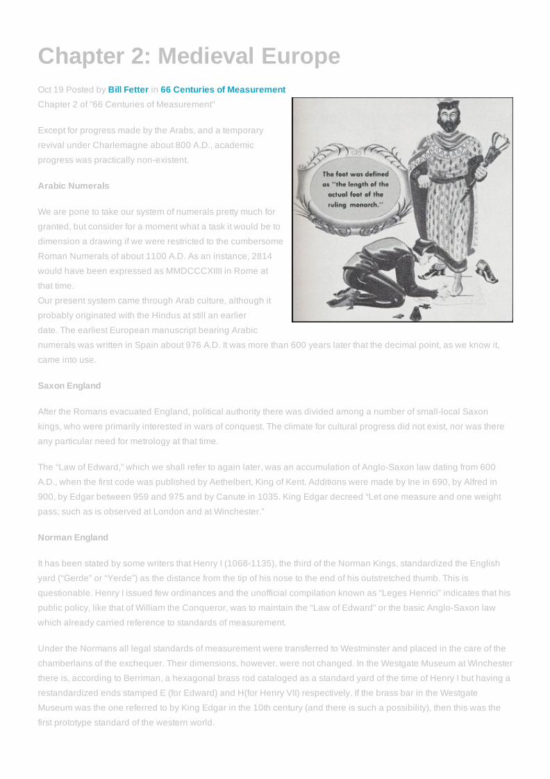
It has been stated by some writers that Henry I (10681135), the third of the Norman Kings, standardized the English
yard (“Gerde” or “Yerde”) as the distance from the tip of his nose to the end of his outstretched thumb. This is
questionable. Henry I issued few ordinances and the unofficial compilation known as “Leges Henrici” indicates that his
public policy, like that of William the Conqueror, was to maintain the “Law of Edward” or the basic AngloSaxon law
which already carried reference to standards of measurement.
Under the Normans all legal standards of measurement were transferred to Westminster and placed in the care of the
chamberlains of the exchequer. Their dimensions, however, were not changed. In the Westgate Museum at Winchester
there is, according to Berriman, a hexagonal brass rod cataloged as a standard yard of the time of Henry I but having a
restandardized ends stamped E (for Edward) and H(for Henry VII) respectively. If the brass bar in the Westgate
Museum was the one referred to by King Edgar in the 10th century (and there is such a possibility), then this was the
first prototype standard of the western world.

With war the principal order of business at that time, and in view of the difficulties that beset the traveler, the importance
of a prototype standard is questionable regardless of its location.
The “Iron Ulna” and the Three Barleycorns
Published accounts have appeared from time to time of the “Iron Ulna” of Edward I and the “Three Barleycorns” of his
successor Edward II.
There was a legal standard known as the Iron Ulna and also a statute defining the inch as the length of three
barleycorns. But considerable doubt exists as to who was as responsible for these standards.
Several compilations of English law dating back to the code of Aethelbert King of Kent (560616) have been published.
The one which is accepted as authoritative by the British Government was made by the Commissioners of Public
Records (18101828). This compilation lists a number of ordinances as being of uncertain date but enacted the century
starting with the coronation of Henry III and ending with the death of Edward II. That would be from 1227 to 1327. The
following are pertinent sections from these ordinances:
(a) Statutum de Admensuratione Terre (Statute of Measuring of Land):
“And it is to be remembered that the Iron Ulna of our Lord the King contains three feet and no more; and the foot must
contain twelve inches, measured by the correct measure of this kind of ulna; that is to say, one thirtysixth part the said
ulna makes one inch, neither more nor less. And 51/2 ulna, or 161/2 feet, make one perch in accordance with the
abovedescribed Iron Ulna of our Lord the King.”
(b) Compositio Ulnarum et Perticarum (Composition – or Size – of Ulna and Perch):
“It is ordained that three grains of barley, dry and round, make an inch; twelve inches make a foot; three feet make an
ulna; 51/2 ulna make a perch; and forty perches in length and four perches in breadth make an acre.”
The Record Commissioners indicate that in some early editions of the British statutes these two ordinances were
combined into one; however, their own authoritative compilation lists them as two separate statutes, both of uncertain
date, and belonging to the time of Henry III, Edward I, or Edward II. Most of the earlier sources also list the dates of
these statutes as uncertain, although one comprehensive listing in British laws assigns the Statute of Measuring Land
to the 33rd year of Edward I (1305).
The second statute is listed as being of uncertain date by Ruffhead as well as by the Record Commissioners. Neither
source, nor any other compilation, lists the date 1324 for the “three barleycorns equal one inch” statute, although this
date is quite commonly cited by historians.
From a study of the personal characteristics and accomplishments of these three monarchs it is difficult to conceive
how either Henry III or Edward II could have been much concerned with standards of measurement. On the other hand,
Edward I was definitely interested in the land laws of England. It seems, therefore, quite possible that Edward I, far
more capable than either his predecessor or his successor, was responsible for both ordinances in question. On the
supposition, it seems natural to ask why he courted confusion by defining the inch in more than one way. There is a
possibility that the three barleycorns standard was legalized only to aid all those who were unable to make use of a
prototype housed at Westminster. After all, in those days high precision was relatively unimportant.
The Yard of Henry VII
There is a reference above to the hexagonal brass standard of the time of Henry I (10681135). On the same authority,
this prototype was restandardized and its ends stamped with “E” for Edward I and “H” for Henry VII, who reigned from
1485 to 1509. If so, why did Henry VII go back at least 350 years for a standard which, as previously pointed out, may
have originated much earlier with King Edgar, when he might just as well have used the more recent “Iron Ulna?” From
the early records, we do know that Parliament under Henry VII was much concerned with standards of commerce and
manufacture which might conceivably have included weights and measures.
To further complicate the question, we have the seventh report of the “Warden of the Standards” (Great Britain) for

1872. This illustrates an octagonal bar graduated in yards on one side and inches on the other and claimed to be the
standard yard of Henry VII. Strangely enough one end of this bar is stamped with what appears to be an “E” and the
other with what might be an “H.” Was this a direct copy of the old standard of Edgar and Henry or Edward I? The
principal difference seems to be that of the hexagonal versus the octagonal cross section. Presumably the “Iron Ulna”
and the three barleycorns remained the legal standards of Britain at least for the 158 years before Henry VII.
Editor's Note:What is this all about?
This is a chapter from the selfpublished "66 Centuries of Measurement Book", third
edition, originally released in October 1984 by the (then) Sheffield Measurement division
of (then) Cross & Trecker. This month to commemorate the release of this book (and
because someone asked us to publish it online), we are publishing a chapter a day on
this blog to look back, and also to see how far we have come as an industry in 28 years.
Please feel free to comment about how you've seen the industry and these products and
processes change in the years since this book was published.
Tags: 66 centuries of measurement

Chapter 3: The RenasissanceOct 22 Posted by Bill Fetter in 66 Centuries of MeasurementChapter 3 of "66 Centuries of Measurement"
During this time the Renaissance had begun. Great
universities such as Vienna, Heidelberg, Leipzig, and
Louvein had been founded. Gutenberg had set up his first
printing press.
Leonardo Da Vinci, the great artist, architect, engineer and
philosopher was making his immortal reputation. In his
notebooks appear several designs for screw cutting
machines. The screw, after a thousand years of oblivion, had
reappeared in Europe.
By 1360 the first mechanical clock had been built by Henry
Wieck of Wurtenberg for Charles V of France.
Gun powder was used for the first time in Europe at the Battle
of Crecy in 1346. Thus, ordnance came on the scene.
One of the earliest lathes was presented in 1500 to the Holy
Roman Emperor Maximilian I, referred to as the last of the knights and the first of the artillerymen. This lathe, made
entirely of wood except for the centers, was operated by a cord wound around the work piece, with one end attached to
a foot treadle and the other to a spring poleoverhead. When the treadle reached the floor, the operator backed his tool
out and let the spring pole lift the treadle back to its original position, reversing the rotation of the work on its return. By
repeating the process, the work piece could finally be finished.
From the death of Henry VII until the accession of Elizabeth to the British throne, a period of 49 years, little of interest in
the fields of science and metrology may be noted, except for the monumental work of Copernicus. Sixty odd years
before the telescope was invented. Copernicus challenged the accepted Ptolemaic Theory of astronomy and
announced the Copernican Theory which has had universal acceptance ever since.
English Rod
An old sixteenth century woodcut shows the English rod being defined by the total length of the left feet of the first
sixteen men to come from church on Sunday morning.
The Yard and Ell of Queen Elizabeth
In her busy and intrigueridden reign Queen Elizabeth found time to issue new exchequer standards known as the
“Yard” and “Ell.” The latter was primarily a standard for cloth measurement. Both were end standards, and both are
engraved wit the initial “E” together wit the royal crown.
These remained the legal British standard until 1824 when they were superseded by an Act of Parliament under
George IV.
The great accomplishments of this era included those of Galileo Galilei, John Napier, William Gascoigne and Pierre
Vernier – accomplishments essential to future progress in metrology.
Galileo
In 1581, when he was seventeen years old, Galileo was not yet acclaimed a great scientistphilosopher. At prayer in

the cathedral of Pisa, he became conscious of the annoying rattle of a chain which he saw to be the support of a
hanging lamp. It had carelessly been left swinging. Then he noticed that the clicks made by the chain seemed to be
rhythmical and regular, even though the arc through which the lamp swung gradually decreased. That was the
inspiration which led to his discovery of the primary law of the pendulum, to be used later as the basis for the work of
Huyghens, Picard, and Richter.
Although a Dutch spectacle maker, probably Hans Lippershey, discovered the optical principle of the telescope, it was
Galileo who produced the first 32power telescope in about 1610.
Galileo carried in where Archimedes left off, materially advancing mechanics to the status of a science. He clearly
grasped the idea of force as a mechanical agent. He developed the laws of falling bodies and the curve of a projectile
in flight.
Napier's Logarithms
John Napier, a Scottish mathematician, in 1614 published his “Canonis Descriptio” embodying his discovery of
logarithms. It was Napier, also, who first used the decimal point to express fractions.
The Slide Rule
Using Napier's logarithms, William Oughtred in 1621 devised the first slide rule. The slide rule was used almost
universally by engineers until the early 1970's when the electronic calculator became popular.
Gascoigne and the Micrometer
It was William Gascoigne, an astronomer, killed at the age of 24 in one of the battles of the Civil War of 1642, who first
used the screw thread as a means of measurement.
Gascoigne had set himself the task of measuring the diameter of the sun, moon, and other celestial bodies by means of
a sort of triangulation. This required a very accurate measurement of the diameter of his target at the eyepiece of his
telescope, which might have been one that Galileo had built. Any error in the measurement of the image in his
telescope he knew would throw his calculations out tremendously.
To a rifleman, a thirtysix inch bullseye at a thousand yards appears about the size of a pea. As the distance increases,
the pea gets relatively smaller. Gascoigne figuratively had to measure the pea in order to computer its subtended
angle.
The next question was how to measure the image in his telescope. A scale graduated even to hundredths of an inch
would have been far too crude. But even if a finer scale had been available, the difficulty in reading it with human eyes
would have ruled it out. Another means of measurement was imperative.
Gascoigne solved his problem by devising calipers, the indicating fingers of which were moved simultaneously in
opposite directions by a screw having a left hand thread on one end and right hand thread on the other.
He could measure the number of threads per inch with a graduated scale and thus compute the pitch of the screw.
Likewise he could compute the advance for any fractional turn of the screw. Such was the basic idea in 1638 upon
which the modern micrometer was based. According to his own records, Gascoigne was able to measure angles to
seconds.
It would be natural to ask where Gascoigne got the threaded element for his screw calipers. The record doesn't cover
this point, but it is the French engineer Besson built in 1569 – the first machine devised for cutting threads. Besson was
able to cut threads of any pitch within reason by means of interchangeable pulleys and a lead screw.
The Vernier Scale
It is doubtful that Gascoigne's screw caliper had a vernier for greater precision in reading. It might have had, for Pierre
Vernier in 1631, seven years earlier, had published in Brussels a treatise entitled “Construction Usage et Propietes du
Quadrant Noveau de Mathematiques” in which he described the vernier.

Metrology, like other sciences, depends on and is influenced by work and discoveries in other fields more or less
closely related. Such is the case with the accomplishments of Huyghens, Picard, and Richter, all of whom made use of
Galileo's preliminary work on the basic law of the pendulum.
The Pendulum as a Standard of Measurement
Christiaan Huyghens, a Dutch mathematician, astronomer and physicist, in desperate need of an accurate time piece
for astronomical work, either hit upon the pendulum idea himself or borrowed it from a contemporary. Huyghens
determined that the pendulum, depending on its length, could be made to beat any desired time interval. In other words
the vibration interval of a pendulum is a constant determined by its length. Huyghens built a pendulumcontrolled clock
and presented it to the StatesGeneral in 1657.
Hyghens is also credited with developing the basic wave theory of light in 1665.
Even at this time the concept of a standard of measurement which could be derived from or tied into some natural
constant was being considered.
Jean Picard
Jean Picard, probably on the basis of Huyghen's work, suggested in 1671 that the length of a pendulum beating
seconds be taken as a fixed and easily recoverable standard of length.
After his original suggestion of the “seconds” pendulum, Picard realized that the diurnal motion of the earth would
introduce a variable. He reasoned correctly that a pendulum of given length would swing more rapidly at the north and
south poles than it would at the equator. He tried to prove this theory but failed. Picard did, however, measure the
meridian from Mahoisine to Amiens, deducing the value of one degree as 68.945 miles.
Sir Isaac Newton
Sir Isaac Newton, who spelled out the mechanics of the universe, had no direct interest in metrology as such but he
contributed nevertheless. Had he carried his investigation of the nature of light a little farther, he might have anticipated
by more than two hundred years the very valuable concept of interferometry.
Newton's fame rests primarily on his statements of the laws of motion and gravitation. Shortly after graduation at
Cambridge he invented differential calculus, and his PRINCIPIA was the greatest book published up to that time.
Editor's Note:What is this all about?
This is a chapter from the selfpublished "66 Centuries of Measurement Book", third
edition, originally released in October 1984 by the (then) Sheffield Measurement division
of (then) Cross & Trecker. This month to commemorate the release of this book (and
because someone asked us to publish it online), we are publishing a chapter a day on
this blog to look back, and also to see how far we have come as an industry in 28 years.
Please feel free to comment about how you've seen the industry and these products and
processes change in the years since this book was published.
Tags: 66 centuries of measurement

Chapter 4: The Eighteenth CenturyOct 23 Posted by Bill Fetter in 66 Centuries of MeasurementChapter 4 of "66 centuries of Measurement"
Jacques Cassini
A proposal for a permanent standard of length came in 1718
from Jacques Cassini, head of the Paris Observatory. After
measuring the arc of the meridian from Dunkirk to Perpignan,
Cassini suggested as a permanent standard of length 1/6000
part of a minute of the great circle of the earth –
approximately one third of our present yard.
Early 18th century metrology was by and large a personal
matter of the comparatively few persons who had any reason
to be concerned with it. There were, of course, the Yard and
the Ell of Queen Elizabeth, but these were relatively
inaccessible to the individual craftsman or merchant.
Manufacturing was still in the cottageindustry stage and
each small shop or forge had its own set of standards.
The best examples of early shop standards are the “Polhem Sticks” or Rods used in the early 18th century in Sweden
and mentioned by Torsten K.W. Althin in his book C.E. JOHANSSON. These were fixed size gages made of iron,
incorporating steps or studs to define several of the dimensions required in the shops where they were used.
Further evidence of the chaos in measurement that characterized the eighteenth century is found on the legend of a
map of Tyrol made in 1774. This map had several scales of miles each divided into feet.
One was the “Common German Mile” which was taken as 1/15 of a degree at the equator. This is subdivided into
23,524 “Work Shoes of Vienna” and 22,272 “Work Shoes of Innsbruck.”
Another was the “Great German Mile” subdivided into 32,000 “Innsbruck Work Shoes.”
Still another was the “Italian Mike” or 1/60 of a degree at the equator. This contained 5,881 Vienna Work Shoes or
5,568 Innsbruck Work Shoes,
The Tempo Increases
The last half of the eighteenth century proved to be a turbulent and eventful period. The American and French
revolutions were fought. The British Museum and the Royal Academy were founded. Priestley discovered oxygen. It
was the era of Gluck, Haydn, Mozart, and Beethoven. James Watt did his monumental work on the steam engine and
Eli Whitney had started to demonstrate the practicability of interchangeable manufacture.
The spinning jenny, the water frame, and power loom ushered in the “Factory System” in England, which was to bring
about drastic political and economic changes.
Within the scope of metrology such names as Thomas Jefferson, Bird, Shuckburg, Troughton, and Kater appear. It was
in this period, also, that the Metric System was brought into being.
James Watt and the Steam Engine
The operations of James Watt, the famous steam engineer of this period, cast light on the status of manufacturing
equipment then available.
Having undertaken the task of improving the Newcomen engine, Watt applied his analytical and inventive mind to the
engine's limitations and to the solution of the theoretical problems involved in it improvement. But his problems were

not restricted to design. He ran headlong into the serious limitations of metal cutting tools then available.
More specifically, he needed steam cylinders and at the start here were no machines capable of boring a cylinder with
accuracy sufficient for his purpose. He got the difficulty at first by hammering the cylinder into shape over a wooden
mandrel.
After nearly four years of work on another cylinder which was bored, rags, cork, and an old felt hat were still needed as
packing to keep the steam from leaking excessively around the piston.
It was not until John Wilkinson in 1774 devised a boring bar with a support at its outer end, that reasonably true
cylinders could be bored. Watt's partner, Boulton, wrote in 1776: “Mr Wilkinson has bored us several cylinders almost
without error; that of 50” in diameter which we put up at Lipton (or Tipton) does not err the thickness of an old shilling in
any part.”
Watt coined the term “horsepower.” In order to impress prospective buyers with the power of his engine, he found out
by experiment how much weight a strong dray horse could lift a distance of one foot in one minute. On that basis, his
engine had the power of 40 horses and that proved convincing to his prospects.
Editor's Note:What is this all about?
This is a chapter from the selfpublished "66 Centuries of Measurement Book", third
edition, originally released in October 1984 by the (then) Sheffield Measurement division
of (then) Cross & Trecker. This month to commemorate the release of this book (and
because someone asked us to publish it online), we are publishing a chapter a day on
this blog to look back, and also to see how far we have come as an industry in 28 years.
Please feel free to comment about how you've seen the industry and these products and
processes change in the years since this book was published.
Tags: 66 centuries of measurement

Chapter 5: Birth of InterchangeableManufactureOct 24 Posted by Bill Fetter in 66 Centuries of MeasurementChapter 5 of "66 Centuries of Measurement"
Until the close of the eighteenth century, the only
craftsmanship known was the craftsmanship of individuality:
that, for instance, which enables a sculptor to chisel a face
with such fidelity that the marble becomes recognizable as
the image of a certain person.
The individual craftsman made a product in its entirety, fitting
each component as he went along. Depending on his
training and ability, his products were more or less
acceptable, but no two similar products or components were
identical. Indeed, there was no particular reason at the time
why they should be, so long as manufacturing was limited to
very small lots. This, of course, is not the craftsmanship of
multiple and precise duplication on which modern industry is
founded.
This concept began to be recognized as production volumes increased, as it became evident that economy demanded
further division of manufacturing labor, and as the demand for replacement parts began to be a problem.
One of the first artisans to see the economic possibilities of interchangeable part manufacture was a French gunsmith
by the name of LeBlanc. In 1785 Thomas Jefferson, as United States Minister to France, heard about LeBlanc, who had
worked out a plan for interchangeable musket parts manufacture 15 years previously. Jefferson was keenly interested
and endeavored to bring LeBlanc to the United States but failed.
The first period of the Napoleonic Wars emphasized the imperative need for interchangeable parts. For the first time,
very large armies with firearms were put into the field. This brought an unprecedented demand for muskets which
craftsman, working on the old basis, met after a fashion. However, the maintenance of these arms soon became a
problem of the first magnitude. Each spare part had to be made and fitted individually – a slow and very expensive
operation. At one time the British Government had 200,000 stands of muskets awaiting repair – probably more than
were in serviceable condition. It was a problem that had to be solved.
The two essentials for interchangeability are reliable measurements and machine tools. As previously mentioned,
there was no uniformity in measurement standards, and machine tools were in their infancy.
Eli Whitney – Father of Mass Production
Eli Whitney, a Yale graduate about 1793, is perhaps best known for having devised the first mechanical cotton gin.
Although a financial failure for its inventor and is partner Phineas Miller, the cotton gin was to put the southern cotton
industry on its feet economically. It was not, however, Whitney's greatest contribution to American progress.
Whitney recognized the wastefulness of handicraft methods of manufacture just as the Egyptians had done nearly five
millenniums before the Christian Era. He also realized that if more than one workman were to contribute to a final
product, the work of each must be controlled dimensionally in order that all components would assemble when brought
together. This, of course, is the essential characteristic of interchangeable parts manufacturing on which any successful
mass production operation is based.
Whether Whitney knew anything of LeBlanc's ideas is not known. In any event, LeBlanc had only a theory – an
unproved theory.

In his effort to manufacture cotton gins on a quantity basis, Whitney indicated the policy of dividing the work into a
number of separate operations, each of which was handled by a worker trained for his own particular job.
The idea was sound enough and might have been successful. The trouble was that most of the skilled craftsmen had
previously left New England for the fabulous prospects of life in the new Western Reserve. Parts made under Whitney's
system by the unskilled apprentices he was able to hire, failed to assemble. Reworking proved costly, as is always the
case, so after many setbacks Whitney and his partner closed their cotton gin business in 1797.
The following year Whitney, still convinced of his manufacturing philosophy, wrote to the Secretary of the United States
Treasury:
“By the debates in Congress I observe that they are about making some preparations for procuring arms, etc. for the
United States... I should like to undertake to manufacture ten or fifteen thousand stand of arms.”
“I am persuaded that machinery moved by water, adapted to this business, would greatly diminish the labor and
facilitate the manufacture of this article. Machine for forging, rolling, floating, boring, grinding, polishing, etc. may all be
made use of to advantage.”
Whitney proposed to manufacture these arms on his new principle – to make the same parts of different guns as much
alike as the successive impressions of a copper plate engraving. Ordnance officers laughed at the idea; his promise of
10,000 stand of arms in two years was preposterous by handicraft methods.
With the help of his friend Thomas Jefferson, Whitney got the government contract in 1798 and began setting up the
Whitney Armory at Whitneyville just outside of New Haven. Then, faced with the same obstacles that plagued James
Watt, he had to build a plant, all his jigs, fixtures, gages, and most of his machinery – a tremendous undertaking in view
of the primitive state of the mechanical arts at that time. Tooling up actually took much longer than anticipated but an
extension in delivery time kept Whitney in business.
In 1799 Whitney went to Washington with a box of parts for ten muskets. Before an audience consisting of President
John Adams, Thomas Jefferson and other officials, he assembled the muskets as each of the officials handed him the
parts picked up at random from the pile on the table. Whitney thus proved his theory of interchangeable parts
manufacture was practicable. Later, with his plant fully tooled, he proved the real economy of his ideas. In 1822 Mr.
Calhoun, Secretary of War, said that Whitney's methods were saving the United States $25,000 a year.
When the British decided in 1853 that something should be done to revitalize their Enfield arms plant, a Royal
Commission was sent to investigate the American system. In accordance with James Nasmyth's recommendations, the
American system was installed in the Royal Armory and American tool builders furnished much of the new equipment
needed.
During the period of toolingup the Armory at Whitneyville, Whitney developed his milling machine. This was also about
the time that Roberts in England brought out his handdriven metal planer.
With the quality and economy of the Whitney musket established, further government contracts contributed to build a
prosperous business.
As Whitney's death in 1825, his son Eli II took over the business, and after him the grandson Eli III. In 1888 the entire
plant sold to the Winchester Repeating Arms Company. Whitney, a man of vision and courage, worked always to his
motto: “There is nothing worth doing that is not worth doing well.”
Cannon Specifications
An interesting sidelight on metal working toward the end of the 18th century, is shown by the tolerances allowed the
manufacturer of cannon for the United States Navy.
In 1794 a contract was let for 34 iron cannon to fire a 32 pound shot and 35 more pieces to fire 24 pound shot. These
were to be used on the frigates Constitution and Constellation.
The tolerance on bore diameter was plus .10” and minus .05”. Holes in the bore could not be more than .225”. It is quite
apparent why naval engagements of that time had to be fought out at very close range.
Chapter 6: The Metric SystemOct 25 Posted by Bill Fetter in 66 Centuries of MeasurementChatper 6 of "66 Centuries of Measurement"
For more than a hundred years before the meter was legalized, scientific minds had recognized the need for a
universal standard of measurement. Preferably a standard based on some natural constant.
The suggestions of Jean Picard and Jacques Cassini have already been mentioned. In addition, there was the
proposal of Gabriel Mouton in 1670 to adopt the arc of one minute of a great circle of the earth as the standard.
Sir Humphry Davy suggested the diameter of a glass capillary tube in which water would rise by surface tension to a
height just equal to the tube's diameter.
In 1790 Thomas Jefferson, then Secretary of State, in a report to the Congress recommended a standard based on the
length of a seconds pendulum. Unlike the pendulums of Picard and Cassini, Jefferson's pendulum was to have a
constant cross section throughout – no concentrated weight at the lower end and half again as long as the weighted
end pendulum. Such a pendulum would be about 583/4” long. Jefferson further suggested this pendulum be
subdivided into five equal parts or feet and each foot be divided into ten equal parts or inches. This report, like so many
since, was merely filed.
Metre Des Archives
The French National Assembly in 1790 appointed a committee to study the several suggestions that had been made
for a basic standard of length. Its decision was in favor of a standard that would be one tenmillionth of a quadrant of
the earth's meridian.
The geodetic survey which served to establish this length was made from Dunkirk in France to Montjuich in Spain.
Another committee, composed of the members of the National Institute of France and certain foreign deputies, was
given the task of drawing up the system of weights and measures and preparing prototypes. This committee produced
in 1799 a platinumiridium end bar known thereafter as the “Metre des Archives.” This was to have been the master
standard of the world. Its length is on the same order of magnitude as that of the seconds pendulum.
France legalized the Metre des Archives in 1799 and in 1801 made the use of the Metric System compulsory.
The Committee Meter
Under the direction of J.G. Tralle, a deputy from the Helvetic Republic, fifteen iron bars similar to the Metre des Archives
were constructed for distribution to the deputies of his committee. One of these which came to be known as “The
Committee Meter” was presented by Mr. F.R. Hassler.
When Mr. Hassler came to this country in 1805 he presented the standard to the Philosophical Society of Philadelphia.
Later, when he became superintendent of the Coast Survey, he used the Committee Meter as a reference.
France Rejects the Meter
Although the meter became the legal standard, French authorities for a time found it impossible to enforce its use.
Practically every French city had its own standards and continued to use them in defiance of the national law. Finally,
attempts at enforcement were completely abandoned when Napoleon became First Consul. No further efforts to
enforce the law were made until 1837 under Louis Phillippe.
Subsequent to the construction of the “Metre des Archives,” discrepancies were discovered in the geodetic survey on
which this standard is based. Its length was found to be one part in 5000 shorter than one tenmillionth of the quadrant
of a meridian.

Efforts to Universalize the Meter
At the time the metric system was being considered by France, Talleyrand proposed a joint commission of France and
England to consider establishing the meter as a universal standard. Had that idea succeeded, subsequent generations
of manufacturers would have been saved a great deal of inconvenience.
By 1870 the metric system had been adopted by Holland, Belgium, and Italy. Still, it was far short of being the universal
standard that France had hoped it would become.
Holding to that objective nevertheless, France invited the nations to a conference in 1870 to discuss the advisability of
constructing new metric standards to supplant those of the Archives. Fifteen nations sent delegates to this conference,
including France herself, Austria, Columbia, Ecuador, Great Britain, Greece, Italy, Norway, Peru, Portugal, Russia,
Spain, Switzerland, Turkey and the United States. Work, however, was seriously handicapped by the turmoil of the
FrancoPrussian War then in progress. Little was accomplished.
A subsequent conference, in 1872, was more successful. It resulted in a decision to reconstruct the basic metric
standards to conform in length and weight with those of the Archives. A permanent committee was organized to carry
this decision into effect. By 1875, its work was sufficiently complete for another general convention to be called.
The International Bureau Established
At this convention of 1875, a treaty was negotiated whereby a permanent International Bureau of Weights and
Measures was established.
A place for the Bureau's headquarters was provided by France at Sevres, a suburb of Paris in the Parc de St. Cloud.
The land was designated international territory.
The Bureau under an elected government committee of 14, no two from the same country, undertook to authenticate
the new standards, act as custodian of the International Prototypes, and make comparisons between them and the
national standards of other countries.
New International Standards
Thirtyone meter bars and forty kilograms had been constructed by 1889 and approved by the Bureau's governing
committee. The bar and kilogram which agreed most closely with their respective counterparts at the Archives were
selected as the new International Standards. The remainder were distributed to the nations represented in the Bureau.
The United States received Meters No. 21 and 27 together with Kilograms No. 4 and 20.
The new meter bar composed of 90% platinum and 10% iridium was made in what is termed the Tresca section, for
maximum physical rigidity. This, the International Prototype Meter, is kept in a massive concrete vault, guarded by
heavy iron doors three flights of steps below the ground floor of a white stone building in the Parc de St. Cloud.
At each General Conference, held every six years, the delegates descend the steps, open the iron doors and enter the
vault to formally inspect the International Prototype in its triple case of glass, vulcanized rubber and wood.
The International Prototype Meter, unlike its predecessor of the Archives, is a line standard instead of an end standard.
It has three microscopic lines engraved on its web at either end. The distance between the central lines in each group
of three under certain conditions defines the meter. These conditions are that the measurement be made at normal
atmospheric pressure, the meter bar being at the temperature of melting ice and supported on two rollers one
centimeter in diameter and symmetrically placed 572 mm apart. No reference was made to either the Metre des
Archives or to the length of the earth's quadrant.
Light Waves
The International Conference of Weights and Measures at its meeting in 1927 adopted a secondary definition of the
meter in terms of the wave length of red cadmium radiation, based on the work of A. A. Michelson and E.W. Morley
nearly 30 years previously. The length, as thus determined, is 1,553,164.13 wave lengths under specified conditions of
temperature, humidity, and atmospheric pressure.

Beginning in 1960, the meter has been defined as 1,650,763.73 wavelengths of orangered light emitted by electrically
excited atoms of Krypton86 gas. The Krypton lamp is immersed in liquid nitrogen and its light output is used in an
interferometer to measure length.
Current Definition of the Meter
The nations of the world, meeting at the General Conference on Weights and Measures in Paris in October, 1983,
adopted a new definition for the meter. Based large on research by the National Bureau of Standards, the new method
defines the meter as the distance traveled by light in a vacuum during 1/299,792,458 of a second.
National Bureau of Standards Director, Ernest Ambler, terms the new definition a “ real breakthrough” for
measurement science. “It not only allows us to define the meter 10 times more accurately, but also achieves a long
sought goal of using time – our most accurate measurement – to define length.”
Editor's Note:What is this all about?
This is a chapter from the selfpublished "66 Centuries of Measurement Book", third
edition, originally released in October 1984 by the (then) Sheffield Measurement division
of (then) Cross & Trecker. This month to commemorate the release of this book (and
because someone asked us to publish it online), we are publishing a chapter a day on
this blog to look back, and also to see how far we have come as an industry in 28 years.
Please feel free to comment about how you've seen the industry and these products and
processes change in the years since this book was published.

Chapter 7: The Nineteenth CenturyOct 26 Posted by Bill Fetter in 66 Centuries of MeasurementChapter 7 of "66 Centuries of Measurement"
By the beginning of the 19th century, such basic machine tools as Wilkinson's boring mill and a screw cutting lathe of
sorts had been built in France. The lead screw and change gears had been used in France, but it was the first half of
the 19th century that witnessed really great expansion in the machine tool industry. By 1850 practically all the basic
machine tools had been developed. During this period Henry Maudsley developed the engine lathe, the index milling
machine and the first screw machine made entirely of metal. Whitworth contributed his end measures and the
Whitworth thread form. Eli Whitney built his milling machine; Roberts, his planer; and the principle of the crowned
pulley was discovered.
Imperial Standard of Britain Under George
The British were naturally interested in the new Metric System, but not sufficiently so to abandon their traditional Yard.
Rankine's verse although penned forty years later, expressed the popular view.
Some talk of millimeters,
and some of kilograms
And some of deciliters
to measure beer and drams
But I'm a British Workman,
too old to go to school
So by pounds I'll eat,
and by quarts I'll drink,
And I'll work by my threefoot rule.
The Elizabethan Yard remained the British standard until four years after George IV took the throne. Then, by an act of
Parliament in 1824, all previous laws relating to standards, including Elizabeth's, were repealed. Thereafter, all
measures of length were to be based on a standard Yard constructed under the direction of the Parliamentary
Committee of 1758.
An abstract from that act reads as follows:
SECTION I. Be it enacted...that from and after the first day of May, one thousand eight hundred and twentyfive, the
Straight Line or Distance between the Centers of the Two Points in the Gold Studs in the Straight Brass Rod now in the
Custody of the Clerk of the House of Commons, whereon the Words and Figures “Standard Yard, 1760” are engraved,
shall be and the same is hereby declared to be the Extension called a Yard; and that the same Straight Line or
Distance between the Centers of the said Two Points in the said Gold Studs in the said Brass Rod, the Brass being at a
temperature of sixtytwo Degrees by Fahrenheit's Thermometer, shall be and is hereby denominated the “Imperial
Standard Yard.”
SECTION III. And whereas it is expedient that the said Standard Yard, if lost, destroyed, defaced, or otherwise injured,
should be restored to the same Length by reference to some invariable natural Standard; and whereas it has been
ascertained by the Commissioners appointed by His Majesty to inquire into the subject of Weights and Measures, that
the Yard hereby declared to be the Imperial Standard Yard, when compared with a Pendulum vibrating Seconds of
Mean Time in the Latitude of London in a Vacuum at the Level of the Sea, is in the proportion of Thirtysix Inches to
Thirtynine Inches and one thousand three hundred and ninetythree tenthousandth Parts of an Inch; Be it therefore
enacted and declared, that if at any time hereafter the said Imperial Yard shall be lost or shall be in any Manner

destroyed, defaced, or otherwise injured, it shall and may be restored by making a new Standard Yard, bearing the
same proportion to such Pendulum as aforesaid, as the said Imperial Standard Yard bears to the Pendulum.
Bird's Yard Bar
It may be of interest to note that this is the first British standard to be designated an “Imperial” standard. It was made by
Bird in 1760 using as an unofficial reference a yard measure made in 1742 for the Royal Society which in turn was
based on the Elizabethan Standard. Bird's Imperial Standard with all its legal distinction and care had probably the
shortest official life of any national standard – just a few days more than nine and half years. It was badly damaged by
the fire which burned both houses of Parliament in 1834. When pulled out of the rubble it was found that one of the
gold plugs had been melted out – consequently, as a standard it was useless. It seems to have been lost until 1891
when it was again brought to light by a Clerk of the Journals. It was then removed to the residence of the Clerk of the
House.
Restoration of the Imperial Standard
After the Parliament fire, it was necessary either to restore or to reproduce the burned standard. The wording of the
statute was very explicit about the reproduction procedure but this did not preclude considerable difficulty in its
execution. It seems that errors were discovered with reference to the determination and use of the control pendulum –
errors serious enough to make the pendulum impracticable for the purpose. Fortunately there were some unofficial
standards which had been compared with the Imperial Standard before the fire. These included the Shuckburgh Scale,
the Yard of the Royal Society and two iron bars A1 and A2 belonging to the Ordnance Department.
The Shuckburgh Scale (036”) was made by Edward Troughton in 1798 and found to agree closely with Bird's Bar. It
had also been compared with the pendulum and the meter.
Troughton seems to have been the first to use a microscope for the purpose of precise comparison and transfer of
precise measurements.
The actual work of reproduction was begun by Sir Francis Baily. It was Baily who, before his death in 1844, decided on
the material of which the new standard was made – copper 16, tin 21/2, and zinc 1.
The Rev. R. Sheepshanks took over Baily's task at his death and, from an average of the standards mentioned above,
produced “Bronze No. 1.” Its graduations are engraved on the polished surfaces of gold plugs depressed to a plane
which coincides with the neutral axis of the bar. Depressing the graduated plugs was done to neutralize errors that
might result from flexure when comparisons were being made.
Accurate duplicates were made of Bronze No. 1 for official use in Britain and were legalized by Parliament in 1855. In
addition, 40 more copies were made for distribution to other governments. One of these Bronze No. 11, was presented
to the United States Government in 1856.
Editor's Note:What is this all about?
This is a chapter from the selfpublished "66 Centuries of Measurement Book", third edition, originally released in
October 1984 by the (then) Sheffield Measurement division of (then) Cross & Trecker. This month to commemorate the
release of this book (and because someone asked us to publish it online), we are publishing a chapter a day on this

Chapter 8: Standards of the United StatesOct 29 Posted by Bill Fetter in 66 Centuries of MeasurementChapter 8 of "66 Centuries of Measurement"
Colonial Times
The early standards of weight and measure in what was later
to be the United States were all of English origin inasmuch as
we started as English colonies. While the Yard of Queen
Elizabeth was theoretically the basis for British length
measure, the technique of duplicating a precision standard
was rather sketchy in the early days. As a result, the alleged
copies of Elizabeth's Yard that came into the several
American colonies from time to time lacked a great deal in the
matter of precise agreement. Naturally, this confusion
became progressively more irritating to the colonists as
American culture developed.
Articles of Confederation
The question of uniformity in weights and measures was therefore given consideration in the Articles of Confederation
when they were undertaken by a congressional committee in 1776. This document includes the following: “The United
States in Congress assembled shall also have the sole and exclusive right and power of regulating the alloy and value
of coin struck by their own authority, or by that of the respective States – fixing the standard of weights and measures
throughout the United States.” Congress promptly used its authority to regulate the currency but seemed reluctant to do
anything but consider the question of national standards of weight and measure.
Washington Urges Action
President Washington, recognizing the necessity, stated in his first message to Congress: “Uniformity in the currency,
weights and measures of the United States is an object of great importance, and will, I am persuaded, be duly attended
to.” This resulted in a request to Thomas Jefferson, then Secretary of State, to prepare a report outlining the procedure
for developing uniform standards. Jefferson's report contained alternate plans. The first was to unify existing weights
and measures. The second was to simplify both weights and measures by decimal subdivision. As has happened so
many times since, Congress dallied with this project ineffectively until 1799 in spite of Washington's continued
insistence on action.
The Fifth Congress did pass an act requiring the surveyor of each port to examine weights and measures used at the
port twice a year and report disagreements to the collector of customs there. In the absence of any standards of
comparison, the act was practically meaningless and, in fact, was not enforced for about 30 years after its
passage. Further Congressional attempts were made to deal with the problem in 1817 and 1819, and resulted in a
complete report from the then Secretary of State John Quincy Adams to the House of Representatives in 1821. This
report suffered the same fate as that made by Jefferson some 30 years before.
Congress Had a Difficult Problem
Perhaps Congress should not be criticized too harshly for its desultory tactics on this issue, which in reality was far from

a simple piece of routine legislation. The metric system had met such popular resistance that it had been abandoned.
The British system of weights and measures was not wholly in accordance with the miscellaneous standards in use in
America, nor was it too well established even in Britain. Would either system survive? No one knew.
The States Act Independently
Without national leadership each of the several states set up its own standards regardless of the actions of other states.
The old confusion persisted. The yard, the foot, and the inch were all peculiar to localities and changed at state
boundaries. This was the status of weights and measures when, in 1824, Parliament under George IV established new
British Imperial Standards to supersede those of Queen Elizabeth. How much effect this had on Americans, it is hard to
say, but it doubtless had some. Britain had now made a serious effort to clear the atmosphere, spell out the rules, and
minimize uncertainties with respect to standards.
The First Legal Standard of Weight
In the United States, the law makers could be somewhat casual about the exact length of the inch or yard, but they
could not be so informal about the exact amount of gold or silver that went into coins. Money was too important. The
British had a new imperial troy pound and the indication was that it had a degree of permanence. It may, of course,
have been just a coincidence, but when Congress, in 1828, passed an act to continue the Mint at Philadelphia, it
adopted this new imperial troy pound. An excerpt from the act states: “And be it further enacted, That, for the purpose of
securing a due conformity in the weight of coins of the United States – that brass troy pound weight procured by the
minister of the United States of London in the year one thousand eight hundred and twentyseven, for the use of the
mind and now in the custody of the Mint at Philadelphia, shall be the standard troy pound of the Mint of the United
States, conformably to which the coinage thereof shall be regulated.”
This was a brass weight and an exact duplicate of the British imperial troy pound according to Captain Kater who
compared the two. This weight became the basis of the avoirdupois point still used in this country. It is obvious that
even Congress could not ignore the question of length standards forever. Two years after we had acquired the troy
pound, legislative machinery was set in motion again for the purpose of acquiring such a standard.
The Treasury Department Takes the Initiative
The Secretary of the Treasury was ordered to report on the weights and measures in use by the principal custom
houses. Except for the recently legalized pound, Mr. F. R. Hassler, Superintendent of the Coast Survey who headed the
investigation, found himself in the same position as the port surveyors in 1799 when they were faced with the same
problem: no length standard with which local measures could be compared. In this case, the Treasury Department on
Hassler's recommendation, chose to comply with the spirit of the order. That left no alternative but to usurp the
prerogative of the Congress and establish standards even though they were not official.
These standards were the gallon of 231 cubic inches, the bushel of 2,150.42 cubic inches and a brass scale of 82
inches made by Edward Troughton of London and brought to this country by Hassler. The yard was defined as the
distance between the 27th and 63rd inch marks on this Troughton Scale.Hassler's work was so well received that the
House of Representatives passed a resolution in 1836 authorizing the Treasury Department to have copies of its still
unofficial standards made for each of the custom houses and for other purposes.
The Office of Weights and Measures
In order to carry out this program, the Office of Weights and Measures was created under the Superintendent of the
Coast Survey. By 1850 practically all the states had a set of the Hassler Standards. When the United States received
Bronze No. 11 in 1856, it was compared with the Troughton Scale. The latter was found to be .00087” longer than
Bronze No. 11.

The Meter Becomes the U.S. Standard
Bronze No. 11 and a second copy of the Imperial Yard received later were considered better standards than the
Troughton Scale and therefore replaced the Troughton Scale as the basic reference of the Office of Weights and
Measures. They remained our standards, although still unofficial, until 1866 when Congress passed the act legalizing
the metric system. This act gave the United States its first and only legal standards of weight and measure.
Excerpts from the act of July 28, 1866 follows:
“Be it enacted by the Senate and House of Representatives of the United States of America in Congress assembled,
that from and after the passage of this act it shall be lawful throughout the United States of America to employ the
weights and measures of the metric system, and no contract or dealing or pleading in any court shall be deemed
invalid or liable to objection because the weights or measures expressed or referred to therein are weights or
measures of the metric system.
Sec. 2. And be it further enacted, That the tables in the schedule hereto annexed shall be recognized in the
construction of contracts and in all legal proceedings as establishing in terms of the weights and measures now in use
in the United States the equivalents of the weights and measures expressed therein in terms of the metric system; and
said tables may be lawfully used for computing, determining, and expressing in customary weights and measures the
weights and measures of the metric system.”
The Treasury Department was ordered to provide each state with a set of metric prototypes. This assignment was
carried out by the Office of Weights and Measures using the “Committee Meter” and the Arago Kilogram for reference.
These remained our official standards until 1893.
Meters No. 21 and No. 27
As previously states, after the International Bureau of Weights and Measures was established, new International
Standards were constructed. The United States, a signatory power, received Meters No. 21 and 27 together with
Kilograms No. 4 and 20. After formal verification in 1893, the Superintendent of Weights and Measures with the
authority of the Secretary of the Treasury, decided that the new international prototypes would replace the earlier metric
standards for use in the United States. As a matter of fact, the new international prototypes were practically identical in
size with their predecessors according to comparisons made at the time.
Current Standards
Kilogram No. 20 remains the official legal standard of mass in the United States, while as mentioned earlier, the meter
is now defined in terms of the distance light travels in a vacuum during a precisely measured time interval. The yard is
defined legally in terms of the meter.
Editor's Note:What is this all about?
This is a chapter from the selfpublished "66 Centuries of Measurement Book", third
edition, originally released in October 1984 by the (then) Sheffield Measurement division
of (then) Cross & Trecker. This month to commemorate the release of this book (and
because someone asked us to publish it online), we are publishing a chapter a day on
this blog to look back, and also to see how far we have come as an industry in 28 years.
Please feel free to comment about how you've seen the industry and these products and

Chapter 9: Precision DevelopmentsIncluding the MicrometerOct 30 Posted by Bill Fetter in 66 Centuries of MeasurementChapter 9 of "66 Centuries of Measurement"
Henry Maudslay, one of the founders of the machine tool
industry, recognized the imperative need for precision in any
machine designed to make elements for other
machines. Incidentally Joseph Whitworth, later knighted, and
James Nasmyth, both to win renown in that field, were
apprentices in Maudslay's organization.
It was Maudslay who built the first screwcutting lathe entirely
of metal in 1800. The critical element of this lathe was a
master lead screw. Maudslay's problem then became the
production of a precision lead screw. It was somewhat the
same as the old question of which came first, the chicken or
the egg. It is true that Besson, a French engineer, had built a
screw cutting lathe more that 200 years before Maudslay was
born, but it probably did not measure up to Maudslay's ideas
of precision. We are told that it took about ten years of diligent work on Maudslay's part to produce a satisfactory lead
screw.
Although Maudslay did not invent it, he did build a screw micrometer caliper in 1805, for use in his own shop, that was
probably the most accurate instrument of that day. He called it “The Lord Chancellor.” It was a benchtype instrument
(not a hand micrometer) about 16 inches long. The basic scale was graduated in tenths of an inch. The end of the
actuating screw had a milled head graduated in 100 divisions, each of which represented a jaw movement of .001”.
James Nasmyth remarked at the time, “Not only absolute measure could be obtained by this means, but also the
amount of minute differences could be ascertained with a degree of exactness that went quite beyond all the
requirements of engineering mechanism; such, for instance, as the thousandth part of the inch.” No reference has been
found relative to Maudslay's standards of length. Presumably they were derived from the yard of Queen Elizabeth
because at that time the Imperial Yard had not yet materialized.
There is no intention to leave the impression that the above are the only achievements of Maudslay. He built his index
milling machine in 1829 and other tools. He also built the engine in 1823 for the first steamdriven ship of the Royal
Navy – H.M.S. “Lightning.” This was sixteen years after Fulton's steamboat made its trial run, and two years before the
Erie Canal was opened.
Sir Joseph Whitworth
Joseph Whitworth, 22 years younger than Maudslay, was doubtless influenced by the older man's reverence for
precision and also perhaps by Maudslay early preoccupation with screw threads. Ideas of this scope have always
been a challenge to men with ambition and integrity.After his apprenticeship in and about London he set up his own
tool shop in Manchester in 1833.
One of his early special interests was the surface plate which his mentor, Maudslay, had introduced. The surface plate

has just two important characteristics – a plane surface and rigidity. Rigidity is not much of a problem but securing a
true plane surface is quite another matter. In a paper presented in 1840 to the British Association in Glasgow he stated,
“A true surface, instead if being in common use, is almost unknown.” That, of course, was in 1840. And Whitworth
referred not only to surface plates but also to the surfaces of engine slide valves, printing press tables, machine tool
slides, and other surfaces required to be true.He described in this paper the method for obtaining a true plane which
won general recognition. Starting with three approximately plane surfaces, he arbitrary chose one as a model, bringing
the other two up to conformity with it. Then he brought the second two into conformity with each other. In the final step
he brought the arbitrarily chosen model into conformity with the remaining two. The whole process was accomplished
by scraping – not by grinding.
By the time Whitworth organized his own shop the yard had been stabilized, at least officially, but the form of screw
threads was still pretty much a matter of personal preference. A bolt with is mating nut, once made, were kept tied
together until they could be used. It was only an outside chance that a bolt made in one place would mate with a nut
made elsewhere. Whitworth, in 1841, started a personal campaign to bring order out of this chaotic condition by
promoting a thread form designed by himself that has ever since been known as the Whitworth Thread. His efforts were
reasonably successful in England. It took another twenty years before American industry became sufficiently annoyed
by the lack of standardization to do much about it. Other significant contributions by Whitworth were his end standards,
interchangeable gages, and measuring machine.
The Whitworth measuring machine, the most precise instrument of its kind up to that time, was sensitive to a millionth of
an inch, its principle elements were a frame of great rigidity, the precision lead screw and the graduated micrometer
disc, all of which had previously been known and used. The new idea was his “feeling piece.” Whitworth realized that
in dealing with end measures to that unheard of degree of accuracy, the amount of gaging pressure was extremely
important and must be controlled; therefore, the feeling piece – a small disc of steel having parallel polished faces.
With the feeling piece between the gage jaw and the work part, only sufficient pressure is exerted to keep the feeling
piece from dropping out. Whitworth developed, in 1834, three bars equal in length and, combined, equal to the Imperial
Yard. He likewise subdivided the foot into inch end measures and, finally, the inch into sixteenths. As working gages,
Whitworth suggested the now familiar plug and ring gages.
The Micrometer
The principle of the micrometer caliper or the use of the screw thread for precision measurement was discovered by
William Gascoigne, a young astronomer of Yorkshire, England, in 1637. The inventor, however, was not concerned
with the measurement of mechanical elements and could hardly have foreseen the future possibilities of his discovery.
In fact, he made no attempt to patent his device. It took more than two centuries to translate Gascoigne's idea into the
machinist tool.
We are told that James Watt used a micrometer which is now on exhibit in London's South Kensington Museum.
The “Lord Chancellor,” a bench micrometer, made by Henry Maudslay in 1805 had already been described.
The first patent on a “Screw Caliper” was issued to a French mechanic, Jean Laurent Palmer, in 1848. This was a
pocket instrument and the forerunner of our present micrometer. Palmer proceeded to manufacture his device under
the name “Systeme Palmer.” What success Palmer had in promoting it is not known.
A biography of Joseph R. Brown states that in 1852 he invented and constructed a dividing engine which he then used
to construct a vernier caliper reading to the thousandths, but nothing more is known about that instrument. It is rather
difficult to fit this incident into the story of the micrometer because of what transpired later.
It seems that in 1867 there was trouble between the Bridgeport Brass Co. and the Union Metallic Cartridge Co. about

the thickness of sheet brass furnished to the latter. The shipment in question was returned as unacceptable. Bridgeport
rechecked the sheets and found them to meet specifications. The trouble was that the Union Co. also had a gage, but it
and the Bridgeport gage differed. Both differed with a third gage brought in to settle the dispute. But all were supposed
to be based on the United States Standard for Wire Gages adopted in 1857. It was definitely a situation that called for a
remedy. The superintendent of Bridgeport Brass, Mr. S. R. Wilmot designed a micrometer which measured to
thousandths. It was read by a pointer which moved across and engraved spiral having the same pitch as the
micrometer screw. Axial lines on the engraved spiral indicated the size of the micrometer opening. What made it
difficult to read was that the graduations were so close, there was no room for figures. Nevertheless, Wilmot had six of
these micrometers made by Hiram Driggs. He also tried unsuccessfully to interest Brown and Sharpe in their
manufacture. Their objection was that the instrument was too complicated to be practicable.
About the same time J. R. Brown and Lucian Sharpe, visiting the Paris Exposition, saw a Palmer Micrometer. Using
what they considered the best features of both the Palmer and Wilmot designs, they brought out the Brown and Sharpe
Micrometer in 1867. This was the first practical mechanic's micrometer marketed in this country. By 1877 it was well
established in our metalworking industry.
Editor's Note:
More than 140 years later, Brown & Sharpe micrometers arestill available, because Brown & Sharpe lives on as a Hexagon
Metrology product line. The image on the right is of the
Micromaster caliper, available along with other types including
digital readout and IP54 models, from many fine online
merchants including Amazon.com, Grainger and MSCDirect.
What is this all about?
This is a chapter from the selfpublished "66 Centuries of Measurement Book", third edition, originally released in
October 1984 by the (then) Sheffield Measurement division of (then) Cross & Trecker. This month to commemorate the
release of this book (and because someone asked us to publish it online), we are publishing a chapter a day on this
blog to look back, and also to see how far we have come as an industry in 28 years.
Please feel free to comment about how you've seen the industry and these products and processes change in the
years since this book was published.
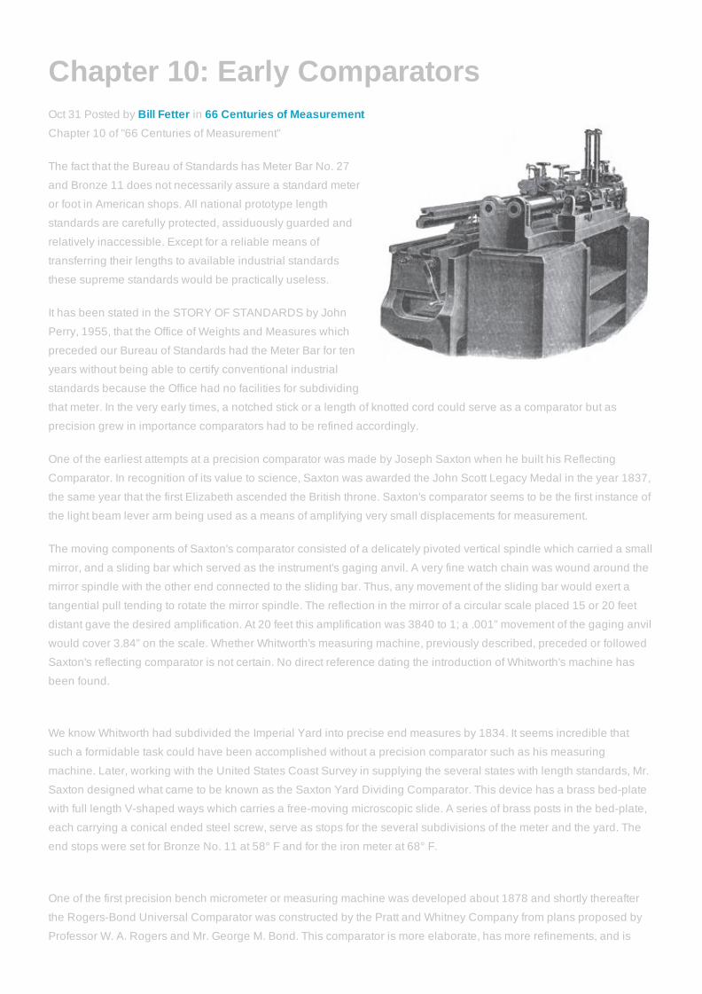
Chapter 10: Early ComparatorsOct 31 Posted by Bill Fetter in 66 Centuries of MeasurementChapter 10 of "66 Centuries of Measurement"
The fact that the Bureau of Standards has Meter Bar No. 27
and Bronze 11 does not necessarily assure a standard meter
or foot in American shops. All national prototype length
standards are carefully protected, assiduously guarded and
relatively inaccessible. Except for a reliable means of
transferring their lengths to available industrial standards
these supreme standards would be practically useless.
It has been stated in the STORY OF STANDARDS by John
Perry, 1955, that the Office of Weights and Measures which
preceded our Bureau of Standards had the Meter Bar for ten
years without being able to certify conventional industrial
standards because the Office had no facilities for subdividing
that meter. In the very early times, a notched stick or a length of knotted cord could serve as a comparator but as
precision grew in importance comparators had to be refined accordingly.
One of the earliest attempts at a precision comparator was made by Joseph Saxton when he built his Reflecting
Comparator. In recognition of its value to science, Saxton was awarded the John Scott Legacy Medal in the year 1837,
the same year that the first Elizabeth ascended the British throne. Saxton's comparator seems to be the first instance of
the light beam lever arm being used as a means of amplifying very small displacements for measurement.
The moving components of Saxton's comparator consisted of a delicately pivoted vertical spindle which carried a small
mirror, and a sliding bar which served as the instrument's gaging anvil. A very fine watch chain was wound around the
mirror spindle with the other end connected to the sliding bar. Thus, any movement of the sliding bar would exert a
tangential pull tending to rotate the mirror spindle. The reflection in the mirror of a circular scale placed 15 or 20 feet
distant gave the desired amplification. At 20 feet this amplification was 3840 to 1; a .001” movement of the gaging anvil
would cover 3.84” on the scale. Whether Whitworth's measuring machine, previously described, preceded or followed
Saxton's reflecting comparator is not certain. No direct reference dating the introduction of Whitworth's machine has
been found.
We know Whitworth had subdivided the Imperial Yard into precise end measures by 1834. It seems incredible that
such a formidable task could have been accomplished without a precision comparator such as his measuring
machine. Later, working with the United States Coast Survey in supplying the several states with length standards, Mr.
Saxton designed what came to be known as the Saxton Yard Dividing Comparator. This device has a brass bedplate
with full length Vshaped ways which carries a freemoving microscopic slide. A series of brass posts in the bedplate,
each carrying a conical ended steel screw, serve as stops for the several subdivisions of the meter and the yard. The
end stops were set for Bronze No. 11 at 58° F and for the iron meter at 68° F.
One of the first precision bench micrometer or measuring machine was developed about 1878 and shortly thereafter
the RogersBond Universal Comparator was constructed by the Pratt and Whitney Company from plans proposed by
Professor W. A. Rogers and Mr. George M. Bond. This comparator is more elaborate, has more refinements, and is

more versatile than its predecessors. It is adaptable to both line and end standards and offers a choice of five separate
methods of comparison. Readings are made by 150 power microscopes having micrometer eyepieces graduated in
divisions of 1/60,000”. It is said that readings can be interpolated by eye to tenths of a graduation. The following is an
excerpt from the report of the Committee on Standards of Gauges at the annual meeting of the American Society of
Mechanical Engineers in New York City, November, 1882. Ambrose Swasey was a member of this committee. “The
completion of the RogersBond Comparator marks a long stride in advance over any method hitherto in use for
comparison and subdivision of linemeasure standards, combining as it does all the approved methods of former
observers with others original with the designers. Comparisons can thus be checked thoroughly by different systems,
so that the final results of the series may be relied on as being much nearer absolute accuracy than any hitherto
produced.”
Editor's Note:
The image at the top of this page is of the RogersBond
comparator, and did not appear in the original book. Few
people would recognize the RogersBond comparator or the
earlier Saxton version as comparators without a explanation.
The illustration on the left is from patent #1,903,933, filed
May 21, 1925, and begins to resemble the form of what we
would recognize today as an optical comparator. Comparator
technology is largely being overtaken today by vision
inspection technology, such as our Optiv camera basedvision inspection systems, which offer greater flexibilty in a
smaller footprint.
What is this all about?
This is a chapter from the selfpublished "66 Centuries of
Measurement Book", third edition, originally released in
October 1984 by the (then) Sheffield Measurement division of
(then) Cross & Trecker. This month to commemorate the release of this book (and because someone asked us to
publish it online), we are publishing a chapter a day on this blog to look back, and also to see how far we have come
as an industry in 28 years.
Please feel free to comment about how you've seen the industry and these products and processes change in the
years since this book was published.

Chapter 11: Screw Thread StandardizationNov 01 Posted by Bill Fetter in 66 Centuries of MeasurementChapter 11 of "66 Centuries of Measurement"
The standardization of screw threads to achieve
interchangeability has been as difficult a problem and
perhaps more costly than the establishment of accepted
length standards.
As previously mentioned, Sir Joseph Whitworth was the first
prominent crusader in the cause of standardization. Starting
in 1841 he finally persuaded British industry to accept the
Whitworth Thread. However, this thread system was based
on the inch, which made it awkward for the metric countries,
and consequently left them comparatively unresponsive.
At that time American industry had not progressed far enough
to realize the necessity for standardization. It was not until the
time of the rapid railroad expansion that American industry
began to realize the economic waste of screw thread
confusion. In 1840 America had less than 3,000 miles of rail lines. Ten years later mileage had nearly tripled and by
1860 we had more than 30,000 miles of railroads in operation. In this expansion, together with the concurrent
expansion of all the supporting industries, nuts and bolts became important items. Waste due to confusion had become
too costly.
Whitworth's American counterpart proved to be William Sellers of Philadelphia, who, after a careful study of the
situation, drew up a screw thread system which he had reason to believe superior to Whitworth's. The chief points of
difference were the thread angle and the contours of root and crest – changes made in the interest of greater
manufacturing economy and more effective inspection but without jeopardizing strength, frictional resistance or wear
life. Mr. Sellers recognizing the magnitude of his task, appealed for support to the Franklin Institute of Philadelphia.
Founded in 1824, the Franklin Institute was the oldest institution in the United States dedicated to the study and
promotion of the mechanical arts and applied science. The Franklin Institute opened Philadelphia's first high school in
1826.
The Franklin Institute responded favorably, and approximately a year before the close of the Civil War a committee was
appointed “to investigate the question of the proper system of screw threads, bolt heads and nuts to be recommended
to the Institute for general adoption by American Engineers.”
This committee reported its findings December 15, 1864. In the course of its investigation the committee was amazed to
discover the very large number of screw thread varieties then in current use. The economic implications were
obvious. In a rather lengthy report the committee recommended the Sellers System. Copies of the report were then
forwarded to several branches of industry concerned, the railroads, and the government agencies.
The Navy's Bureau of Steam Engineering adopted the Sellers system in 1868, the Pennsylvania Railroad in 1869, the
Erie Railroad in 1874. It was also adopted by the Master Mechanics Association, the Master Car Builders Association,
and others. Thus the Sellers system came to be the American Standard with benefits for American industry comparable
with those British industry derived from the Whitworth system.

Both countries got along reasonably well until the outbreak of the First World War. Then, suddenly, American, British,
and French industries were faced with a common production task but with five different screw thread systems. These
were: American Standard, S.A.E., British Standard Whitworth, the British Standard Fine, and the Metric Standard. In
addition, the Metric Standard has several variations. It is needless to say that the cost in delays, dollars, and lives was
serious. However, the pressure of the conflict left no opportunity to remedy the situation.
At the close of the war, an attempt to reconcile BritishAmerican differences proved fruitless. In 1926 a British mission to
the United States proposed a compromise of 571/2 degrees between the Whitworth 55 degree thread angle and the
American 60 degree angle. The problem remained unsolved as time drew closer to another emergency. World War II
caught the industry of both countries still unprepared for effective cooperation in the matter of screw threads. Again the
costly delays in turning out urgently needed aircraft engines and ordnance. But again the pressure of war postponed
any effort to correct the difficulty.
It wasn't until December of 1943 that the problem of unification was attacked again, this time by a conference in New
York. This was followed by two conferences in London in the summer of 1944 and a final conference in Ottawa in
September of 1945. The result was agreement on the 60 degree thread angle and a compromise on root and crest
contours.
Group conferences of American, British, and Canadian delegates completed formulas for computing tolerances and
allowances late in the 1948. On November 18th of that year a Declaration of Accord was signed by the representatives
of the three countries and our present Unified Screw Thread Standards became a reality at least for the United States
and British Commonwealth.
Editor's Note:What is this all about?
This is a chapter from the selfpublished "66 Centuries of Measurement Book", third
edition, originally released in October 1984 by the (then) Sheffield Measurement division
of (then) Cross & Trecker. This month to commemorate the release of this book (and
because someone asked us to publish it online), we are publishing a chapter a day on
this blog to look back, and also to see how far we have come as an industry in 28 years.
Please feel free to comment about how you've seen the industry and these products and
processes change in the years since this book was published.
Tags: 66 centuries of measurement

Chapter 12: Precision Gage BlocksNov 02 Posted by Bill Fetter in 66 Centuries of MeasurementChapter 12 of "66 Centuries of Measurement"
The man who did more than any of his predecessors to bring
precision measurement directly into the machine shop was
Carl Edward Johansson. When he conceived his gage block
idea, the tool room had not yet evolved. In 1887, at the age of
23, Johansson started his apprenticeship in Carl Gustaf's
Rifle Factory at Eskilstuna. This organization supplied the
Swedish army with rifles. The very purpose of such a product
made its reliability imperative; this, in turn, required precision
manufacture. Thus is was quite natural for the young
apprentice to become precision conscious.
The precision of that day, however, left much to be desired
according to modern standards. The control measuring
instruments then in the Rifle Factory consisted of snap gages, sliding calipers, and one micrometer reading to .01 mm.
The manufacturing gages were steel blocks, one for each dimension. Although the idea of tolerances had been
recognized, none were shown on working drawings.
When the Swedish government decided to adopt a magazine rifle, the manufacturing problem was further complicated
by a far greater number of precise components parts. An order for these magazine rifles was placed with the Mauser
Werke, a German firm. The contract provided that the new rifles were to be inspected by a commission from the
Eskilstuna plant, and that this commission be given sufficient production information to permit further production to be
carried on at Eskilstuna. Johansson was a member of this commission, which went to Germany in 1894.
The task of producing individual gage blocks in the customary way for the many critical dimensions for the new Mauser
appalled Johansson. Surely there must be a more effective way to control dimensions. Then his great idea occurred to
him: a set of blocks increasing in uniform size increments which could be used singly or in combination to equal any
manufacturing dimension encountered.
On his return to Sweden in 1896, Johansson had completed his computation of block sizes for all dimensions in
increments of .01 mm from .01 mm to 201 mm or a total of 20,000 different dimensions. This set contained 102 blocks in
three series. There remained, however, the more formidable problems of actual production with the limited equipment
and standards then available to him. Besides having to be accurately sized, opposite faces of the blocks had to be
parallel and finished to a much higher degree of smoothness than was customary on commercial products. It was
further realized that unless the blocks were stabilized they would grow with age and thus lose their accuracy.
At first the question of a basic reference standard was not serious because the initial set of blocks was made for use in
the Rifle Factory, which had its own individual length standard. Individual, because it did not necessarily conform with
others in the neighborhood. It had been only 9 years since Sweden adopted the Metric System and the transition was
in progress.
Johansson had access to the Brown & Sharpe micrometers used at the Rifle Factory but he recognized their limitations
when applied to the problem then at hand. There could be a shadow of doubt whenever the screw thread was used to
arbitrate precision measurements, but he had no alternative. Like Whitworth, he sought to eliminate variations in
gaging pressure but in a different manner. Instead of using the conventional thimble Johansson mounted a much
larger graduated drum on the micrometer barrel. A cord wound around the drum carried a weight which exerted a
constant tangential force on the drum and thus kept gaging pressure constant.
Johansson had the utmost faith in his basic idea but lacked the funds to launch its full scale development as an
independent business, so gage block manufacture was started on a parttime basis. Preliminary work on the blocks
was done by the Rifle Factory under contract. All finishing was done at first in Johansson's home work shop with
improvised equipment and during times when he was not at work in the Rifle Factory.
The first set of blocks, having an accuracy said to be .001 mm was turned over to the Rifle Factory during the year 1896
and immediately put into service. Johansson proceeded with this part time business development until 1914 when he
resigned his position as armourer at the factory and thereafter devoted all his time to gage blocks.There was
considerable difficulty at first obtaining a Swedish patent on gage blocks but the patent was finally issued in January of
1904 with priority allowed to 1901. The British patent was issued in 1902.
Another idea developed and patented (1907) by Johansson was what he termed “progressive tolerances.” Prior to that
it had been customary to use a bilateral constant tolerance in making fixed size gages, regardless of their nominal size:
in other words, the same tolerance for a 10 mm gage as for a meter gage. As long as end measures such as gage
blocks are used singly the bilateral constant tolerance concept is tenable, but when used in multiple there can be a
considerable discrepancy in the aggregate length depending on the number of blocks and whether the individual
tolerances are plus or minus.
Johansson advocated the principle of using graduated tolerances based on the lengths of the blocks. The smaller the
block, the smaller the tolerance. For his own work he adopted a tolerance coefficient of .0001 of the block length. This
corresponded closely with the coefficient of thermal expansion of the steel he used to manufacture the blocks.
By 1907 Johansson block sets began to be recognized by American industry. Henry M. Leland of Cadillac was the first
automobile manufacturer to have a set. The United States War Department acquired thirty sets in 1915.
Without detracting from Johansson's important achievement, it must be stated that the indicating shop comparator was
necessary to give the gage block concept its full effectiveness and flexibility. The shop comparator is the only practical
means of bridging block increments.
Editor's Note:
The company founded in 1911 and named for Johansson, CE Johansson AB, became
part of the Hexagon group in 2002, and remains the sole Swedish measurement
company in the Hexagon Metrology portfolio. Gage blocks, regardless of the
manufacturer, are still often referred ot as "JoBlocks" in honor of CE Johansson.
What is this all about?
This is a chapter from the selfpublished "66 Centuries of Measurement Book", third
edition, originally released in October 1984 by the (then) Sheffield Measurement division
of (then) Cross & Trecker. This month to commemorate the release of this book (and because someone asked us to
publish it online), we are publishing a chapter a day on this blog to look back, and also to see how far we have come
as an industry in 28 years.

Chapter 13: Time, A New StandardNov 05 Posted by Bill Fetter in 66 Centuries of MeasurementChapter 13 of "66 Centuries of Measurement"
One of metrology's most valuable instruments was developed
primarily to help solve a scientific problem rather distantly
related to metrology. This instrument is the interferometer; its
inventor, the eminent scientist Albert Abraham Michelson.
As with most human progress, the work of the individual
begins where his predecessors left off and is continued by his
successors. This story really starts with Galileo and it is yet
unfinished.The genesis of the interferometer is that very
elusive scientific phenomenon, radiation. What is the ultimate
speed at which light can travel? This question is basic to the
universal theory of electricity and magnetism and to the
theory of relativity. It has intrigued scientists as far back as
Galileo, who tried ineffectually to determine the speed of light
with a hand lantern. Ole Roemer, a Danish astronomer in the
17th century, concluded that it took 1000 seconds for light to travel the diameter of the earth's orbit.
The first attempt at an accurate laboratory measurement was that of Armand Hippolyte Louis Fizeau in 1849. He was
followed by more than a score of scientists using a variety of approaches. Before 1880 Michelson became interested in
the problem of light velocity and began work in that field. While a professor at the Case School of Applied Science,
Cleveland, Ohio, he undertook to determine what effect, if any, the earth's motion had on the observed velocity of light.
While working on this project in 1887, he contrived his interferometer primarily to aid him with the problem then at
hand.
We know that Michelson had an interest in metrology inasmuch as he was made a member of the Bureau International
des Poids et Mesures in 1882. It seems quite natural, therefore, that he would be quick to see the application of the
interferometer to the precision measurement of such objects as gages and mechanical components. Thus it was that
light waves entered the realm of metrology and were used by Michelson to measure the International Meter Bar in
1892, with the red band of cadmium as a light source. By this measurement he determined the meter bar to be
equivalent to 1,533, 164.13 wave lengths of red cadmium light at 760 mm atmospheric pressure. The wave length of
that red band of cadmium is .00002534838828 inches.
The interferometer incorporates the previous progress made by many scientists, the most outstanding being Sir Isaac
Newton, Christiaan Huyghens, and Thomas Young. It was Newton who developed the spectrum theory, Huyghens who
formulated the wave theory of light, and Young who explained the phenomenon of light wave interference when two or
more waves are superimposed. A continuous sine curve may be taken to represent the wave motion of monochromatic
light. This curve had periodic crests with intermediate troughs. If a second sine curve, the crests and troughs of which
coincide with those of the first curve, is superimposed on the first, the height and depth of crests and troughs are
increased. If, however, the crests of one wave coincide with the troughs of the other, each wave tends to cancel the
other. At intervals of one half wave length, wave motion is cancelled completely. When viewed, these points of
complete cancellation appear as dark bands or “fringes.”Knowing the wave length of a monochromatic light and being
able to count the interference fringes, give us our most valuable standard of measurement.

The scheme of Michelson's interferometer
is shown at left. Monochromatic light such
as red cadmium, passing through the light
slit, strikes the beam divider at an angle of
45°.The Beam Divider is a transparent
plate the sides of which are both flat and
parallel. It is silvered in such a manner that
part of the light reaching it is reflected
toward mirror (A) and part transmitted
toward mirror (B). The intensity of the
reflected beam is approximately equal to
that of the transmitted beam. The surfaces
of both mirrors are normal (perpendicular)
to the light beams which strike them.
Assume for a moment that the
compensator does not exist. Then the
transmitted beam is reflected by mirror “B”
and again by the beam divider to the eye.
The reflected beam is again reflected by
mirror “A” and transmitted by the beam
divider to the eye. Although mirrors “A” and “B” may be equidistant from the point of incidence “O” at the beam divider,
the distances traveled by the two beams in reaching the eye are not quite equal. The transmitted beam has to pass
through the beam divider plate three times whereas the reflected beam passes through but once. The compensator, a
transparent plate with flat parallel sides, is inserted in the optical system to keep the distances traveled by the two
beams in balance. With a balanced optical system, there will be no light wave interference at the eye but a movement
of either mirror will change the length of its respective beam and throw that beam out of phase with the other beam to
cause interference fringes. By counting these fringes, it is possible to measure the amount of mirror displacement. The
amount by which the two waves are “out of phase” due to mirror displacement can be determined to one thousandth of
a wave length. For red cadmiums this amounts to .00000002534838828 inches.
The light interference principle was also utilized by Fabry and Perot who developed a very simple interferometer. This
instrument utilized two flat glass plates from one to five centimeters apart with their surfaces parallel. The inner surfaces
of these plates are silvered so as to reflect most but not all the light which strikes them. Thus, when monochromatic light
is beamed into the instrument, that portion which is transmitted by the first plate is reflected back and forth between the
plates. On each incidence with the second plate some of the light passes through that plate and may be observed. The
air between the plates produces the interference. Further refinements have been made, culminating in modern
instruments such as the Koesters Interferometer, which will be discussed in a later chapter.
Over a period of about 50 years since Michelson measured the International Meter Bar, eight additional observations
have been made with the interferometer and a red cadmium light source. Comparison of the nine results seems to
indicate no apparent change in length of this supreme standard. In spite of this, the evidence thus far cannot be taken
as proof that it will always remain stable. The average of the nine observations is found to be 6438.4696 angstroms. An
angstrom is one hundredmillionth of a centimeter or one tenthousandth of a micron.
One of Michelson's problems was the difficulty of producing monochromatic light in order to attain the desired
sharpness of the spectral lines with well defined fringes. He started by using the yellow radiation of sodium only to
discard it for the green band of natural mercury which he thought would be better. He soon discovered, however, that
mercury was far too complex a substance for his purpose. He finally chose the red band of cadmium as the most

satisfactory source available at that time.
With the advent of nuclear science, natural mercury was found to be a mixture of seven isotopes with atomic weights
196, 198, 199, 200, 201, 202, and 204. Each has its own spectral line. The 16 components of the green radiation cover
a spectral range of more than half an angstrom so it is not hard to understand Michelson's rejection of natural mercury
as a light source. Cadmium is still very useful. In fact, the red radiation of cadmium under prescribed conditions is
accepted as an alternate means of defining the length of the International Meter Bar. Nevertheless, cadmium does
have its limitations as an interferometric light source. Chief among these is that it is necessary to hear the cadmium
tube to approximately 300° C which tends to make the spectral lines fuzzy.
About 50 years ago science set about finding the ultimate in a light source and returned to mercury as the starting
point, fully aware that natural mercury was not the goal. Mercury does have inherent advantages found nowhere else.
The green line of mercury is far more actinic to the human eye than the red of cadmium. Furthermore, mercury requires
less than half the temperature to attain the necessary radiation. Consequently, the spectral lines of mercury are far
more distinct than those of cadmium. The problem was to isolate an isotope of the complex natural mercury, preferably
one having an evennumbered atomic weight. The evennumbered isotopes have no appreciable atomic spin which
tends to blur spectral lines. Mercury 198 was selected.
From work done at the University of California it was learned that by bombarding pure gold with neutrons in an atomic
pile it could be transmuted to mercury 198 as an end product. Thus the United States Bureau of Standards purchased
40 ounces of pure gold and sent it to Oak Ridge for processing. In 1948 Dr. Edward V. Condon, Chief of the Bureau,
told the Paris Conference on Weights and Measures that the task of producing mercury 198 had been completed and
that using this as a light source with an interferometer, measurements could be made to one part in 100 million.
The simplest device for utilizing light wave interference for precision measurement is the optical flat. The optical flat is a
disc up to 10 inches in diameter, made usually of clear fuzed quartz, the latter because of its low coefficient of
expansion. The surfaces are flat to one millionth of an inch. The optical flat is used to detect errors in flatness of a
precision part and also as a comparator to measure its size. Light wave interference is produced by the conflict of the
light reflected from the lower surface of the flat with that reflected from the upper contact surface of the object being
checked. Monochromatic light is used.
To check surface irregularities, for instance, of a gage block surface, the flat is placed against the surface, usually at a
slight angle to form an air wedge between flat and block. If the interference fringes are straight and parallel the block
surface is flat. If they are parallel and curved, the surface is either convex or concave. If they are irregular, the surface
irregularities are thus indicated. By interposing a part and a standard between two optical flats the size of the part is
compared with that of the standard. By measuring the interference fringes all of the above measurements are both
quantative as well as qualitative.
Editor's Note:
The current use of interferometers in measurement involve the use of an interferometer with a laser as the light source.
Thse include precision calibration interferometers and interferometer based laser trackers. At one time, even laser
scales were employed on CMMs (the Sheffield Summit model). Leica Geosystems AB, a Hexagon company,
manufactures laser trackers that employ laser interferometer technology as the measurement principle. You can readmore about the state of the art in Leica interferometer technology in this technical article. We also are an authorized
distributor of the Agilent Dynamic Laser Calibration systems and accessories (available through our online store.)
What is this all about?

Chapter 14: Early 20th Century MetrologyNov 07 Posted by Bill Fetter in 66 Centuries of MeasurementChapter 14 of "66 Centuries of Measurement"
By the end of the nineteenth century the American machine
tool industry had been firmly established and was growing
vigorously with Cincinnati as its capital. Machine tool
progress and the concurrent railroad expansion had provided
the strongest stimuli to metrological development during the
last hald of the nineteenth century. Its basic theory had been
established, and the rewards for further refinement were
becoming increasingly attractive.
The twentieth century did not usher in a new era in metrology,
but almost from the start it provided a strong incentive for
progress. On New Year's day of 1900 William C. Browning of
Browning King & Company said: “In nearly fifty years of
business experience I don't believe I ever saw a time when
prospects were so bright.” Then we had no aircraft, no radios,
no toolrooms, no high speed steel – not even income taxes. The Klondlike gold rush was on; oil had been founf in
California; the telephone was going across country. We had about 8,000 automobiles in the country but no automotive
industry.
Johansson blocks had not made their appearance as yet on this side of the Atlantic. Maximum precision in the shop
depended on the micrometer. The United States was, in fact, the world's principal source for micrometers at that
time. Manufacturing tolerances had not yet been reduced to .001” for two reasons. Such close tolerances were not
required, nor had machine tools reached the degree of precision which would have permitted .001” tolerances.
Tolerances to thousandths didn't come into general use until about 1910. In this country the Office of Standard Weights
and Measures was the legal custodian of our national standards but not particularly active in promoting metrology.
Great Britain still relied on the measuring machine and fixed size gages produced by Sir Joseph Whitworth together
with Americanmade micrometers. Actually, close tolerance work was done by highly skilled craftsmen who relied more
on the feel of a fit than on any measuring instruments.
Developments in the first half of the twentieth century that had the greatest effect in promoting the importance of
metrology were the birth of the automotive industry, the application of massproduction practices, and global war.
Metrology was inherently the essence for success in each: metrology together with its blood brother, the machine tool.
The automotive industry, the most dynamic industry the world has ever known, is a product of the twentieth century, but
it is difficult to fix its exact birithday.
Frank Duryea in 1893 started building a single cylinder, 4 horsepower, buggy type vehicle in New England. The
Detroit Automobile Company which later became Cadillac was started in 1899. The Henry Ford Automobile Company
was formed in Detroit in 1901. The Ford Motor Company was incorporated in 1903. W.C. Durant organized General
Motors Corporation in 1908. David Buick sold his first car in 1904. The Society of Automobile Engineers was launched
in 1905. By that time national annual production of automotive vehicles had reached 25,000. Duryea was probably the
first to freeze a motor car design for subsequent production. Durant pioneered assembly line technique while he was
still manufacturing carriages. He formulated the policy of buying component parts rather than manufacturing them in his

own plant. Each of his suppliers thus developed his own embryo of massproduction of a specialty which thus could be
more effectively and more economically made. From a management standpoint, this practice also relieved Durant of
the hazard of carrying a large inventory on his own books. Massproduction in its current sense began to develop after
the first endless chain conveyor was installed at the Highland Park Plant of the Ford Motor Company in 1911. Ford's
Charles E. Sorensen is credited with the introduction of the powerdriven conveyor assembly line which is basic to
modern massproduction.
Editor's Note:What is this all about?
This is a chapter from the selfpublished "66 Centuries of Measurement Book", third
edition, originally released in October 1984 by the (then) Sheffield Measurement division
of (then) Cross & Trecker. This month to commemorate the release of this book (and
because someone asked us to publish it online), we are publishing a chapter a day on
this blog to look back, and also to see how far we have come as an industry in 28 years.
Please feel free to comment about how you've seen the industry and these products and
processes change in the years since this book was published.
Tags: 66 centuries of measurement
Chapter 15: United States National Bureauof StandardsNov 06 Posted by Bill Fetter in 66 Centuries of MeasurementSince today is election day in the US, I decided to publish this chapter out of sequence since it documents the US
government's contribution to measurement via the "National Bureau of Standards" (today called NIST). Enjoy, and don't
forget to vote! Chapter 14 will be published tomorrow.
Chapter 15 of "66 Centuries of Measurement"
"The basic and primary standards (length, mass, and time) are the principal responsibility of the National Bureau of
Standards.” These were the words, except those in parentheses, of Dr. Allen V. Astin in his address at the dedication of
the Eli Whitney Metrology Laboratory of the Sheffield Corporation in Dayton, Ohio, February 17, 1956.
However, custody of our national prototype standards is by no means the Bureau's only responsibility today. The other
activities will be discussed later. While the Bureau wasn't established until 1901, its progenitor, the Office of Standard
Weights and Measures, had then served as custodian of standards for a period of 63 years. In a previous chapter we
discussed the confusion over weights and measures that plagued this country in its early years, and the unsuccessful
efforts of Washington and Jefferson to prod Congress into action which would give the country uniform standards of
length and weight.
While Congress delayed, the need for standardization became more urgent. Finally, in 1830 during Jackson's first
presidential term, the Senate directed the Secretary of the Treasury to make a comparison of the haphazard lots of
weights and measures then in use by the principal customhouses. Hassler's work in compliance with that order has
been discussed. Six long years later, in 1836 at about the time of the massacre at the Alamo, Congress went into
action, ordering a set of Hassler's unofficial standards to be delivered to each of the States. At that time the only
standard that had been duly legalized by Congress was the troy pound used by the Philadelphia mint to regulate
coinage.
While the act of 1836 did not specifically legalize the Hassler standards, it did bring about a uniformity in the weights
and measures used in the custom service and thus, in practice, by the country at large.
Another joint Congressional resolution in 1838 directed the Treasury to furnish balances to each of the States. There
might be some question as to why these tasks were assigned to the Treasury Department. At that time there were only
four Government Departments – State, Treasury, Law, and Navy. Of these, the Treasury was the most logical, since as
it was already concerned with coinage and it possessed, in the troy pound, the only legal standard we had. It was also
quite logical for the Secretary of Treasury to set up an organization for administering the acts of 1836 and 1838. Thus
was created the Office of Standard Weights and Measures which was laced under the direction of the superintendent of
the Coast Survey. The latter group became the Coast and Geodetic Survey in 1878.
While discussing the executive departments of the government, it may be interesting to note that the Department of
Commerce and Labor was not organized until February 14, 1903, approximately two years after the National Bureau of
Standards continued the work of the Office of Standard Weights and Measures. Then year later, in 1913, the
Department of Commerce and Labor was divided, resulting in the Department of Commerce and the Department of
Labor. Today the National Bureau of Standards is an agency of the Department of Commerce.
A leading figure who served 21 years wit the former Office of Standard Weights and Measures and who had much to do
with the orientation of the Metrology Division of the newly established Bureau was the late Louis A. Fischer. An eminent
scientist and a dedicated metrologist, he did much to bring about a better understanding of the role metrology was to

play in the years ahead. It was Fischer who inaugurated the Annual Conference on Weights and Measures, the first of
which was held in 1905. These conferences, attended by state and local officers charged wit the control of weights and
measures, have done much to propagate good metrological practice. During World War I Fischer was in charge of all
gaging for the War Department.
The ramifications of today's Bureau would bewilder a nineteenth century observer familiar only with the early Office of
Standards Weights and Measures.The act of Congress establishing the Bureau outlined its functions as the
development, construction, custody, and maintenance of reference and working standards; and their comparison,
improvement, and application in science, engineering, industry, and commerce. To the unimaginative congressman of
half a century ago, such verbiage doubtless seemed sufficiently inclusive to launch a small organization such as the
Bureau. After all, there were only fourteen people in this organization at the time.
These lawmakers could not have been expected to realize the magnitude of the fundamental idea they were dealing
with – or its allure for such farsighted men as Fischer, Dr. Condon, Dr. Astin. Today the Bureau is the country's chief
physical research laboratory and its supreme arbiter in the field of physical science. Form a payroll of 14 persons in
1901, its staff has grown to nearly 3000. Of these, about 40 per cent are professional scientists.
The Bureau spreads out over a 68 acre “campus” in northwest Washington. Its buildings house millions of dollars'
worth of the finest scientific instruments and other equipment. Besides the headquarters installation, the Bureau has
laboratories in California and Colorado, twelve domestic stations from coast to coast, and seven overseas stations from
the arctic to the tropics. The scope of the Bureau's operations is indicated by its plan of organization which includes
thirteen divisions: Applied Mathematics; Atomic and Radiation Physics; Building Technology; Chemistry; Electricity;
Electronics; Heat and Power; Mechanics; Metallurgy; Mineral Products; Missile Development; Optics and Metrology;
Ordnance Development; Organic and Fibrous Materials; Radio. The Bureau's many scientific activities include:
Fundamental research in the basic properties of matter;
Applied research in the development of new processes, materials and devices;
Developments involving measurement standards, instrumentation and testing practice;
Calibration of instruments; preparation of standard samples for measurements; development of commodity
specifications and commodity testing for the Federal Government; technical advice to government agencies;
Compilation and publication of scientific and technical information; production of special materials for the Federal
Government; and operation of special installations and services.
The Bureau serves the public directly by furnishing standard samples of materials, testing materials and equipment –
and also by calibrating instruments and standards of measurement where sufficiently precise calibration is not
elsewhere available. Under a Research Associate arrangement, Bureau personnel carry on approved research
projects requested by private organizations which pay the salaries of those involved. The results of such work become
public property and are published.
Some of Bureau's noteworthy achievements have been in fields of atomic energy, guided missiles, radio propagation,
surgical apparatus, panoramic Xray equipment, and monochromatic light. The MeggersMercury 198 lamp,
recognized as the best in interferometry, was developed by the Bureau.
Editor's Note:
In 1984 when this book was published, the information contained herein was no doubt correct. In 1988, the referenced
"National Bureau of Standards" was renamed the National Institute of Standards and Technology" or simply NIST. Thecurrent information on the NIST agency can be found on the NIST website. It remains an agency of the US Departmentof Commerce.

Chapter 16: The Dial IndicatorNov 08 Posted by Bill Fetter in 66 Centuries of MeasurementChapter 16 of "66 Centuries of Measurement"
The familiar dial indicator is a legacy from the 19th century
watchmakers of New England, developed primarily as a
watchmaker's gage. Its broad usefulness to industry in
general was not recognized until later.
It is possible at this time, only to speculate on the motivation
behind its development. It is readily understandable that the
watchmakers, by the nature of their product, were concerned
with precision measurement. But the micrometer had been
available for more than a decade before the appearance of
the dial indicator. The natural conclusion might be that the
technical mind then, as now, was constantly striving for
means to improve the precision and thereby the quality of
manufactured products.
The records of the United States Patent Office show that on May 15, 1883, a patent specification was filed by John
Logan of Waltham, Massachusetts, for what we call a dial indicator. He referred to it as “an Improvement in Gages.”
In outward appearance this instrument didn't differ much from present indicators but its movement was quite
different. Instead of the now familiar rack and pinion, Logan used a fine Swiss watch chain to transmit the motion of the
gaging spindle to the indicating pointer. This chain was wound around a drum, or arbor, which carried the indicating
pointer. One end of the chain was fastened to the gaging spindle, the other to the drum. Amplification depended on the
diameter of the drum and the length of the indicating pointer. The practical limitation on the amount of amplification by
this method was probably the reason that Logan later switched from the chain movement to a rack and pinion
mechanism.
One of Logan's associates was Frank E. Randall, an inventor who learned watchmaking at the E. Howard Watch
Company of Boston. Randall, recognizing more fully the broader market for the dial indicator, bought the Logan patents
in 1896. In partnership with Francis G. Stickney, he undertook the manufacture and marketing of dial indicators to
industry at large. Shortly thereafter, B. C. Ames entered the field, also with a geartype indicator.
Felix Auerbach, writing of the Zeiss Works and the Carl Zeiss Stiftung in Jena, indicates that German industry, too, was
searching for new measuring instruments of greater precision, and for the same reasons.
In 1890 Professor Ernst Abbe established the measuring instrument department of the Zeiss Works. By 1904 this
organization had developed a number of instruments for general market consumption. Among them was a dial
indicator.
Editor's Note:
The illustration shown was not in the original book. It is a dial indicator from the 1913 Brown and Sharpe product
catalog. You can still purchase Brown & Shape dial indicators from many fine online merchants
including Amazon.com, Grainger and MSCDirect.

Chapter 17: The Reed MechanismNov 09 Posted by Bill Fetter in 66 Centuries of MeasurementChapter 17 of "66 Centuries of Measurement"
During the second decade of the 20th century, industrial leaders,
especially those in the young automotive industry, were beginning to
appreciate the value of tolerances closer than those for which fixed
size gages were suitable. William Bagley, chief inspector for
Studebaker, was among the first to advocate replacing these fixed size
gages with instrument gages for mass production operations.
Without precision indicating comparators, the full precision potential of
the gage block standards introduced by Carl Johansson could not be
realized. Nor could parts be classified for selective assembly.
Because of the imprecise character of many machine tools of that day,
selective assembly was about the only way to achieve the precision fits
desired.
The chief obstacle to such progressive concepts was that no practical
precision comparator adaptable to massproduction inspection was
available. This does not mean that there were no precision
comparators. Some have already been mentioned, but they were
laboratory instruments requiring a high degree of skill and
considerable time to operate. They were far too slow for automotive
inspection.
The idea chiefly responsible for circumventing this impasse and opening the way for widespread instrument gaging in
production was the principle of the reed mechanism.
The reed mechanism is an ingeniously simple mechanical device for amplifying small displacements, in this case the
displacement of the gaging spindle. Essentially it consists of two steel blocks and four reeds, the latter made of flexible
strips of spring steel.
The blocks, separated sightly, are connected by two horizontal reeds. One block is anchored to the gage head. The
other, which carries the gaging spindle, is free to move vertically. The two remaining reeds are solidly fastened to the
top inside faces of the blocks, one to each block. These project vertically upward and are joined at their upper ends.
Displacement of the floating block causes the horizontal reeds to flex and the connected ends of the vertical reeds to
sweep through an arc, amplified by a pointer and further by an optical system.
The idea of the reed mechanism was conceived by two metrologists, independently but no concurrently. The first was
Mr. E. Mark Eden, who developed the idea while he was a member of the staff of the Metrology Division of the National
Physical Laboratory of England in 1918. The second was an American. Those attending a gage manufacturers'
meeting in Chicago in 1927 were courteously invited to visit the Western Electric plant and look over that company's
inspection facilities. Although no especial attention was drawn to it, the display there included an instrument
incorporating the reed principle. It had been developed by Mr. Arthur Schoof, a Western Electric Engineer who
apparently was quite unaware of the previous work of Mr. Eden.

Among the visitors that day at Western Electric, the only ones who apparently grasped the significance of the reed
principle were Mr. C. H. Reynolds and Mr. Charles E. Watterson representing the then Sheffield Machine & Tool Co.
They recognized the great potential of tis sensitive, frictionless amplifying device as the basis for a new line of
comparators which could be used in the shop for fast precision inspection by workers who had no special skill in that
area.
The Sheffield Machine & Tool Co. started negotiations with Western Electric for a license to use the reed principle.
This was granted in 1929.
The first commercial comparator to incorporate the reed principle was Sheffield's “Electrigage.” This instrument
showed instantly by light signals whether the part being checked was within tolerance, larger than the maximum
tolerance limit, or smaller than the minimum limit.
By 1930 a second comparator known as the Sheffield “Visual Gage” was introduced. This was an indicating
comparator utilizing the frictionless reed mechanism together with a weightless light beam lever arm for amplification,
and capable of classifying parts for selective assembly.
The Ford Motor Co. was the first automotive manufacturer to use the “Visual Gage” for close limit production
inspection. That was in 1930.
Editor's Note:
The illustration shown above was not in the original book. The Sheffield "Visual Gage" referenced
in the text is now known as the Blanchette/Sheffield Visual Gauge (shown left) and are still
available, although it is not a Hexagon Metrology Sheffield Measurement product. This product
came to our attention in recent years when one of the prop masters from the movie "Oceans
Thirteen" called inquiring about how the device worked, as they wanted to use it in a scene. Unlike
the Global used in Terminator 3, it's believed that that scene ended up on the cutting room floor,as we saw no evidence of it in the finished film.
What is this all about?
This is a chapter from the selfpublished "66 Centuries of Measurement Book", third edition, originally
released in October 1984 by the (then) Sheffield Measurement division of (then) Cross & Trecker. This
month to commemorate the release of this book (and because someone asked us to publish it online),
we are publishing a chapter a day on this blog to look back, and also to see how far we have come as
an industry in 28 years.
Please feel free to comment about how you've seen the industry and these products and processes change in the
years since the book was published.
Tags: 66 centuries of measurement

Chapter 18: Air GaugingNov 12 Posted by Bill Fetter in 66 Centuries of MeasurementChapter 18 of "66 Centuries of Measurement"
Few ideas have exerted the impact on industrial metrology
that pneumatic gaging has. It is one of the spectacular
developments of this century, making available the higher
amplifications to deal with constantly shrinking manufacturing
tolerances and the gaging speed demanded by mass
production operations. It opened the way for multiple and
automatic gaging. In short, it has proved an invaluable aid to
the rapid progress of modern precision manufacturing since
1940.
Basic Principles
According to historical information, the idea of using a fluid as
a gaging medium stems probably from the thinking of
Cruikshank and Fairweather. As early as 1917 they
suggested the relationship of fluid pressure and nozzle area as the basis of measurement and regulation in the field of
paper manufacturing.
Interest in fluids as a means of measurement seemed to spring up spontaneously on both sides of the Atlantic. A
United States patent on an air gage was issued to Harrington in 1922. At about the same time, French engineers took
up the idea, and their contemporary developments are described in United States patents issued to Mennesson.
A. S. Cachemaille in 1923 announced a method by which the longitudinal vibrations of a dynamo shaft were measured
by the flow of gas and water vapor. A similar fluid flow application was made by Guy in England just prior to
Cachemaille's.
Western Electric used fluid flow in determining the flatness of telephone receiver discs. Rifle barrels were gaged by the
leakage of fluid under pressure between the bore and a master plug.
The first application of air gaging principles in the automotive industry was the determination of carburetor jet area by
the Societe Anomyme de Material Automobile (Solex).
Dimensional Air Gages
Although the early work in this field was in the investigation of such characteristics of flatness and area, the experience
thus gained prepared the way for the dimensional air gage.
The dimensional air gage is essentially a comparator which utilizes the effect of small dimensional changes on
metered air in the gaging circuit. It is based on the fact that the free flow of compressed air through an open orifice is
restricted when an obstruction is brought close to it. Such an obstruction reduces the velocity of flow and at the same
time raises the pressure in the circuit behind the orifice. The closer the obstruction is to the orifice, within certain limits,
the more pronounced are these effects.
In the case of the air gage, the orifice is represented by the jet or jets in the air gage tooling. The obstruction is the
surface of the work part being gaged.
By metering either change in backpressure in the pneumatic circuit or change in its velocity flow, the clearance
between the jets in the air gage tooling and the adjacent work part surface is determined.
Whether the designers of the first commercial dimensional air gage realized their purpose could be accomplished by

metering either backpressure or flow velocity, is not known. No practical velocity metering device had yet been
developed.
The first dimensional air gage to be marketed was a backpressure gage. Solex introduced it in 1926.
Backpressure in this first Solex gage was metered by means of a water column manometer. Since then backpressure
metering has been accomplished in several ways – one was a pneumatic transducer developed by Britain's National
Physical Laboratory. Another was the use of bellows and a third was the familiar Bourdon tube. Deformations of the
latter two devices are amplified by a rack, pinion, and pointer assembly similar to that of a dial indicator.
Solex Circuit
Compressed air from a reducing valve enters the gage circuit through a set of restrictions in the outer chamber, which
regulate the volume of flow. Pressure stabilization is accomplished by means of an openend diptube immersed to a
predetermined depth in a water chamber. Since excess air can escape to the atmosphere through the bottom of the
diptube, circuit pressure is governed by the hydraulic head from the bottom of the tube to the water surface.
The air at this governed pressure passes through a control jet to an intermediate chamber. This chamber has two
outlets, one to the manometer and the other to the gage tooling. Differences in backpressure originating at the tooling
jets are read on a graduated scale behind the manometer column.
Three Dimensional Gage
What is considered to be the first air gage widely marketed in the United States was brought out in 1935 by the
Sheffield Gage Corporation for the purpose of exploring the fitness of flat and cylindrical surfaces in three dimensions
simultaneously.
The operating principle was the metering of pressure loss between the work part surface and that of a master.
These gages were used to inspect tubing, hydraulic cylinders, and other components required to hold pressure.
As the possibilities of pneumatic gaging became more apparent, more gagemakers became interested, and variations
in circuitry began to appear. One of these is the Venturitype circuit, which combines characteristics of the back
pressure gages discussed above and the flowtype gage to be described below.
VenturiType Circuit
In this gage, compressed air at regulated pressure enters a large venturi chamber and then passes through the venturi
throat unto the smaller venturi chamber where velocity is higher and pressure lower than in the larger chamber. From
the smaller chamber the air passes out through the metering orifices in the gage tooling.
A pressure tube from the larger chamber allows the higher pressure of that chamber to act on the outside of an
enclosed bellows. A similar tube from the smaller chamber is connected to the inside of the bellows to oppose the
pressure in the bellows chamber. The spring action of the bellows in conjunction wit this pressure differential causes
the bellows to deflect until it reaches equilibrium. This bellows movement, amplified by a rack and pinion, moves a
pointer over a graduated dial.
Differential Circuit
The socalled differential circuit is somewhat similar to the Venturi circuit in its use of a bellows, subject to pressure
differential, and its rack and pinion amplifier.
Pressure regulated air passes into two separate channels, each having an initial fixed restrictor. One channel, which
feeds the bellows cavity, contains an atmospheric bleed for zeroing.
The other channel, connected to the bellows interior, terminates at the orifices of the gage tooling. The pressure
differential in the two channels causes the bellows to deflect until equilibrium is reached. This movement registers the

backpressure in the system during the gaging operation on a circular dial scale.
Bourdon Tube Circuit
The Bourdon tube gage is another example of the backpressure gage. Filtered air from the plant supply passes
through a pressure regulator and a metering restrictor into the gaging circuit. Included in the circuit is a connection to a
Bourdon tube which deflects with circuit pressure changes. These deflections are again amplified by a rack and pinion
mechanism and registered on a circular dial.
The backpressure gage has consistently performed well in the progress of industrial metrology where it is often
preferable to all other types. However, gage engineers, mindful of the trend toward progressively smaller
manufacturing tolerances, wanted to devise some means of raising air gage amplifications without slowing response.
After considerable research, the flowtype principle was announced in 1940. It combined high magnification with swift
response in the familiar Sheffield Precisionaire(R) Column Instrument.
FlowType Circuit
By metering the velocity of air flowing in the gaging circuit, amplifications up to 100,000:1 and even higher may readily
be attained. The flow type circuit is the simplest of all air gaging circuits. It is unique in that it is completely pneumatic,
involving only the flow of air and the movement of a float. It is not complicated by auxiliary mechanical elements.
Filtered air at regulated pressure passes up through a vertical transparent tube having a tapered bore, the smallest
diameter at the bottom. An indicator float in this tube is free to move in response to air flow. When no air is flowing, the
float remains at the bottom of the tube. As air in the circuit begins to flow, the float starts to rise. The greater the air
velocity, the higher the float will rise.
The air leaving the top of the float tube is passed through the escape orifices or jets in the gage tooling. During the
gaging operation, the greater the clearance between these jets and the surface being gaged, the greater the velocity in
the pneumatic circuit. Therefore the position of the float in the transparent tube indicates the amount of clearance
between tooling and work part surface. Float position is read on a graduated scale alongside the tube, the graduations
being in decimals.
The outbreak of World War II brought an unprecedented demand for ordnance of all kinds – a demand which the Allies
were illprepared to meet, especially in the very critical field of ordnance inspection. Gaging equipment at the time was
pitifully inadequate, as was the supply of skilled inspectors.
Gages previously used to inspect small and medium caliber arms required far too much time and skill to meet this
emergency. Had it not been for the new air gaging equipment and technique, which so greatly increased the tempo of
inspection and deemphasized inspection skill, it is questionable how the crisis could have been resolved.
Early Developments
The outstanding developments of the 50's, 60's and 70's have been largely in the field of tooling and masters as well as
the integration of air gaging with other manufacturing operations, such as, machine controls, automatic gaging and
automatic assembly.
Standard tooling for the inspection of bearings, paper, cotton, and other man made fibers were introduced in the 50's
and continue to be used in these industries today.
The development of the “Plunjet” gaging cartridge in the 50's by the Sheffield Corporation, allowed part tolerances of
up to 0.080 to be measured using air gages. These gaging cartridges greatly simplified the design of multiple circuit
gage tooling.
The selection of mating parts, so necessary for the manufacture of precision pumps and servo valves for the automotive
and missile industries, is being accomplished by high amplification air gages commonly referred to as “Selectionaire's.”
Thus, the technique of “match” fitting of parts forms one of the cornerstones of modern mass production manufacturing
methods and its use has become wide spread throughout this country.
During the early years, pneumatic gaging was confined to inspecting internal diameters. Since then tooling has been
developed which makes it practical to inspect all characteristics of an inside or outside diameter, including size, taper,
ovality and straightness. All other external dimensions, such as lengths, flatness, concavity, convexity, center distance,
parallelism, squareness, and concentricity can easily be measured using air gages.
The absence of mechanical contact allows for the inspection of easily deformed parts or those with highly polished
surfaces. Air gaging also provides the ability to inspect very small bores with a selfcleaning action and low
maintenance. Low operator skill requirements and the design flexibility offered to the gage designer have made air
gaging one of the most universally used gaging systems in the world today.
Editor's Note:
Sheffield Measurement products from Hexagon Metrology no longer contain air gauges
in the product line, but this does not diminish their importance in the history of
dimensional metrology for manufacturing.
What is this all about?
This is a chapter from the selfpublished "66 Centuries of Measurement Book", third
edition, originally released in October 1984 by the (then) Sheffield Measurement division
of (then) Cross & Trecker. This month to commemorate the release of this book (and
because someone asked us to publish it online), we are publishing a chapter a day on this blog to look back, and also
to see how far we have come as an industry in 28 years.
Please feel free to comment about how you've seen the industry and these products and processes change in the
years since this book was published.
Tags: 66 centuries of measurement

Chapter 19: Electrical GagesNov 13 Posted by Bill Fetter in 66 Centuries of MeasurementChapter 19 of "66 Centuries of Measurement"
The practical application of mechanicalelectric methods to dimensional gaging made its appearance during the
second decade of this century both in this country and in Europe.
It became apparent to those studying the subject that electrical characteristics might well be utilized as a means of
gage amplification. Also, it appeared that the high sensitivity of the electrical limitswitch could be very useful when
coupled with mechanical gage amplification.
Credit should be accorded to such men as R. Widdington and J. J. Dowling for their pioneering work with oscillatory
circuits, and to R. S. Johnson for his work at the Bureau of Standards on strain gaging.
The “Electrolimit” Gage
Doctor Ford of the Admirality Research Laboratory in 1922 suggested electromagnetic induction as a practical means
of gage amplification. This is the principle around which General Electric and Pratt & Whitney later developed the now
familiar “Electrolimit” gage, during the late twenties and early thirties.
As developed, the Electrolimit Gage was an indicating comparator, utilizing a balanced bridge coil circuit so arranged
that any mechanical displacement of the gaging spindle unbalanced the magnetic field of the two opposing
electromagnetic coils. The amount of imbalance thus caused was recorded by a sensitive ammeter graduated to read
in increments of an inch. Amplification of this gage was easily adjusted by changing the amount of air gap between the
coils. Amplifications up to 10,000:1 were readily attained.
With these early gages, fluctuations in line voltage interfered with gage reliability – a difficultly since remedied by more
effective voltage regulation.
The “Electrigage”
The “Electrigage,” introduced in 1929 by the Sheffield Machine and Tool Company (later The Sheffield Corporation),
was the first commercial limit comparator to incorporate electric signal to indicate whether the part being gaged was
within tolerance, oversize, or undersize. This gage did not indicate the arithmetical value of a dimension.
One of the first of these gages was sold in 1929 to Reo Motors where it served satisfactorily for many years. It is now
part of a display of early gages in the Smithsonian Institution in Washington.
Basically, the “Electrigage” head is an extremely sensitive limit switch. Amplification is entirely mechanical,
accomplished b the frictionless reed mechanism described above, and later used in the “Visual Gage.” The needle
arm of this reed mechanism swings in response to gaging spindle displacement. The swing causes the arm to make
and break adjustable electrical contacts and thus indicate the size of the part being gaged. Maximum and minimum
tolerance limits for the adjustable contacts are set by masters or gage blocks.
Since the function of the electrical current here is merely that of signaling, voltage fluctuations had no effect on gage

reliability.
The “Multicheck Electrigage”
The “Multicheck Electrigage” brought out by the Sheffield Gage Corporation in 1934 was the next step in the evolution
of the limitswitch principle used in the “Electrigage.”
“Electrigage” heads were small and compact. By mounting a number of them on a suitable chassis with a precise
workpositioning fixture, multiple dimensions could be gaged simultaneously. Each gaging spindle actuated its own
signal, so that each dimension could be inspected individually.
In addition, a single master light integrated all the signals. When the master light showed clear, the work part was
passed as acceptable with no need for reference to the individual dimension signals. This proved to be a big time
saver in the urgent inspection of massproduced parts. Without the Multicheck, it would have been almost impossible
to gage adequately the millions of ordnance parts needed during World War II.
General Campbell, Commandant of the Frankford Arsenal at that time, cites the service of one of these gages used to
inspect five critical dimensions of 37 mm. Shells. From the time it was installed in 1940 until the middle of 1944, this
gage inspected 5,815,665 shells – 29,078,325 individual dimensions. This one gage saved more than 4000 days of
inspection time over previous ordnance gaging precedures. During World War II, gages of the Multicheck type
inspected over a billion of the dimensions of ordnance parts.
Automatic Gages
The evolution of the Electrigage principle did not stop even with the “Multicheck.” “Electrigage” heads, which could
actuate relays just as well as signal light, became the sensing of the early automatic gages and also the early
automatic machine controls.
Other Types of Circuits
The acceptance of these first electric gages was a sufficient challenge to gagemakers at large to accelerate their
activity in this field. Other types of circuits were soon to follow.
Electrical circuits for indicating comparators differed chiefly in the electrical characteristics by which the pickup head or
transducer was designed to operate. These involved output voltage, output inductance, output resistance and output
capacitance. Many such electrical circuits are in current use.
In order to get increasingly higher amplifications, electronics came into use in connection with conventional electric
circuits. In this way gage head outputs were amplified many times before being rectified or detected by the meter
circuit. Both electrical and electronic circuits are used in automatic gaging installations today.
Editor's Note:
The foundational work in electrical gauging are the underlying principles behind touch trigger and analog scanning
probes for CMMs in use today.
What is this all about?

Chapter 20: Gaging Progress in the MidTwentieth CenturyNov 14 Posted by Bill Fetter in 66 Centuries of MeasurementChapter 20 of "66 Centuries of Measurement"
Comparators available to industry by 1940 included the dial
indicator, the electric gage, the reed mechanism gage, the air
gage and the multiple gage – all considerably more sensitive
and more dependable for close tolerance work than the old
fixedsize gages which preceded them. Not withstanding
these obvious advantages, many manufacturers, including
prominent organizations int eh automotive and domestic
appliance industries, continued to cling to fixedsize gaging,
a procedure which was not only tedious but which required
many experienced inspectors.
With few exceptions gaging was still a postprocess manual
operation. There were a few automatic gages at the
beginning of the forties, but only a few. Western Electric had
used them for more than a decade. The Ford Motor Company
had automatic gages for checking crankshafts, camshafts, push rods, and valve tappets. Automatic gages were also in
use for checking wire, strip metal and bearing balls.
BallRace Size Control Gage
An interesting example of automatic machine size control of the early forties was the device by ball bearing
manufacturers for the grinding of ball races. This consisted of a Sheffield “Electrichek” gage head, the gaging contact of
which rode the surface of the race being ground throughout its machining cycle. Governed by the size information thus
transmitted to the reed mechanism of the gage head, relays were actuated to control coolant flow and spindle
movement. The sensitivity of this gage was well within .00005”.
An Improved Automatic Ball Checker
By 1943 a new automatic bearing ball checking machine went into service to help break a serious bottleneck in the war
production of ball bearings. This unit simultaneously checked and sorted bearing balls at a rate of from 15,000 to
20,000 per hour, doing in one hour what had previously been considered a full day's quota. Balls from 1/8” to 11/16”
were segregated by size into 10 precise classifications differing by as little as .00005”.
Gaging at the Machine
In the early forties, it was practice to allow processed parts to reach final inspection before being checked for size. By
then, if any maladjustment of the processing machine or cutting tool had occurred, a large batch of rejects would have
accumulated.
Thus, in order to save time and reduce scrap, gagemakers instituted a crusade for the purpose of supplying each
production machine operator with a gaging instrument, right at his machine. This permitted him to check each part as it
was finished and thus catch any mechanical trouble before a lot of scrap parts had been produced. This effort was
reasonably successful.

External Dimensions Gaged by Air
In 1944 the scope of the air gage was materially broadened. While this gage had long since established its proficiency
in the field of internal gaging, it then became equally applicable to precision external gaging. This was the result of the
introduction by the Sheffield Corporation of a new air snap gage.
NonContact XRay Gage
The noncontact Xray gage made its appearance in 1946 and soon found ready acceptance in the rolling mills.
The Xray gage operates on the principle that a given material will absorb Xrays passing through it in direct proportion
to its thickness. Thus, by metering the Xray absorption through a given sample and comparing it with that of a known
standard, the thickness of the material being gaged was determined.
This gage provided rolling mill management with a continuous thickness check of sheet or strip as the material came
from the rolls. It has since become the sensing element of automatic mill roll adjustment mechanisms.
Automatic Cylinder Bore Gage
By 1946 Buick Motor Division of General Motors put into operation the first automatic cylinder bore gaging machine of
the type which was to set the general pattern for the industry. It was developed around the flowtype principle of air
gaging, such as is used in the “Precisionaire(R)” air gage.
This machine simultaneously checked eight cylinder bores at four points in each bore for actual diameters and for any
outofround condition to an accuracy of .0001”. It classified each cylinder in increments of .0003” for the selective
assembly of pistons. All this was done in less than 60 seconds – a spectacular saving in inspection time and in
inspection floor space required.
Operation was almost completely automatic. Cylinder blocks were delivered to the gage, positioned, and removed
automatically. The only requirement of the operator was that he swing the levercontrolled gaging spindle through 180
degrees to check outofround condition, and to stamp the classification code number on each cylinder bore as
indicated by its respective gage reading.
Statistical Quality Control
Statistical quality control emerged as a new science in the field of massproduction. While its scope goes beyond
dimensional control, the latter is one of its important phases and one that stresses the need for precision instrument
gages of the indicating type.
A productive quality control program was instituted in the Gillette Safety Razor organization in 1946. The Ford Motor
Company in 1949 introduced statistical quality control in all its principal divisions. Since then it has spread
progressively through the manufacturing community.
Computers and Numerical Machine Control
Considering the trend of development at the time, it was not strange that there should be a rebirth of interest in the
possibilities of computers and numerical machine control, the all but forgotten ideas of an earlier period.
The pioneers in this field had been Jacquard, Lanson, Babbage, and others who were reasonably successful even
without the benefit of twentieth century electrics, electronics, and pneumatics.
Vannevar Bush, working at the Massachusetts Institute of Technology in 1930, had succeeded in constructing a
machine to solve differential equations mechanically.
With the aid of electronics, highspeed digital computers were developed in 1945 by International Business Machines
at the Harvard Computation Laboratory.
Considerable work on the numerical control concept was done by the Persons Corporation of Traverse City, Michigan,
under a contract with the Air Materiel Command. Further work, also sponsored by the Air Force, which included an

experimental numerically controlled milling machine, was undertaken in 1949 at the Servomechanisms Laboratory of
M.I.T.
The Arma Corporation in 1949, with Doctor Fredrick Cunningham cooperating, introduced a numerically controlled tool
maker's lathe. This machine proved to be an interesting exhibit of the possibilities of this technique, but it was not
successful commercially.
Before the close of the decade, a large number of automatic gaging machines had been put into service. These were
used for checking shockabsorber pistons, automotive pistons, and piston rings.
The “Micronaire” Gage
Toward the end of the forties, a new gage known as the “Micronaire(R)” instrument was developed by Sheffield to
facilitate the accurate determination of the fineness of textile fibers – a characteristic very important to that industry, but
one which previously had required tedious laboratory work for its determination.
The “Micronaire” instrument is another type of pneumatic gage. A weighted sample of fiber is placed in the specimen
cylinder of the gage and compressed to a constant volume. Compressed air at constant pressure is then blown through
the sample, and resistance to this air flow is metered. Resistance is in direct proportion to fiber fineness.
Since its introduction, “Micronaire” measurement has become the official standard of industrial, scientific, and
governmental agencies dealing with textiles throughout the world.
As our economy entered the fifties, nearly five years of pace had allowed industry to catch up somewhat on the pentup
demand for consumer goods.
Our armed forces had been reduced to but a shadow of their wartime strength, and much of our expensive material had
been allowed to deteriorate seriously because of insufficient maintenance personnel. Defense spending dropped to a
little more than ten billion dollars.
Thus, when General Douglas McArthur was ordered to stop the Communist's drive into South Korea, he had neither
adequate manpower nor the equipment to do a workmanlike job. Defense spending then started another rapid climb
that reached 56 billion by the time Korean hostilities ceased in the summer of 1953.
The decade of the fifties was one of industrial expansion. It was further characterized by a shortage of engineers, rapid
growth of monopolistic labor union power, skyrocketing wages and prices. In other words, it was an ideal climate for
stimulating more extensive and more inclusive automation.
Emphasis during this decade was largely on the refinement and elaboration of basic automation techniques. Some of
the outstanding developments were the introduction of air and electronic gaging pickups, development of self
contained electropneumatic control units, and accent on automatic assembly.
Pneumatic and Electronic Pickup Cartridges
The introduction by Sheffield in 1952 of the “Plunjet” air gaging cartridge greatly extended the scope and flexibility of
air gaging and its use as a means of automatic machine control.
The “Plunjet” cartridge is a sensing or pickup unit used with any type of air gage. It consists essentially of an air valve
having a precisely varying orifice area and a mating, springurged conical plunger. The opposite end of the plunger is
the gaging contact. The position of the plunger determines the effective orifice area and therefore the rate of flow
through the orifice and the back pressure behind it. Any change in either flow or back pressure while gaging is directly
proportional to plunger travel. By metering this change, plunger travel is determined and registered on the scale of the
gaging instrument.
Prior to this, air gaging was not generally considered applicable to broad tolerance applications because of the 0.005”
range limitation. The “Plunjet” increased this at least to 0.100”.
Because of its small size the “Plunjet” could readily be incorporated in gaging fixtures of all kinds, especially in multi
dimension fixtures. The first practical jet engine turbine blade gage was based on the “Plunjet” which checked 18
dimensions simultaneously. It greatly simplified gaging fixture design not only specific dimensions, but for the checking
of geometrical relationships of elements in an assembly. The “Plunjet” cartridge has proven equally effective as a

control for grinding, turning, boring, and honing machines.
Transformer principles has been in use for some time to obtain dimensional measurements with vacuum tube
amplifiers. These efforts were handicapped by the size of the transducer and the size of the electronics. The precursor
of Linear Variable Displacement Transducer (LVDT) gaging technology of the '70's and '80's was brought out in 1956
by Sheffield. The “Electrojet” unit was based upon the use of LVDT principles. A magnetic core whose position (or
displacement from null) produces outofphase signals from two opposed secondaries of a small transformer. Careful
design keeps the combined signal errors insignificant and permits fast accurate measurements to be made, even for
millionths.
Its size often accommodates direct measurements far more economically than more elaborate mechanical designs to
using larger units. The real advantage was to be realized when transistors and then integrated circuit technology
permitted multidimensional checks to be performed on automatic gages and housed in small, reasonably sized
enclosures.
SelfContained ElectroPneumatic Control Units
The air gage as a solo instrument had a single function: that of dimensional evaluation with the result shown visibly on
a scale. When the air gage became an integral part of the automation symphony, a second function was added. Some
action on the basis of dimensional findings had to be taken. That action might be to allow a machine to continue
operation or to stop it. It might be to change from roughing to finishing cuts. It might be to transfer a part to a succeeding
operation, to classify it, or reject it as scrap. The possibilities were and are unlimited.
Such actions are conveniently accomplished by servomechanisms, usually driven electrically. Pneumatic gage action
then has to be translated into electrical energy. The fact that highspeed machine tools are often involved makes it
highly desirable to accomplish this translation in a minimum time interval.
Thus it was that the “Airelectric” gage head was developed in the early nineteen fifties. This device was a limittype
pneumatic sizecontrol system capable of making and breaking electric contacts. It is sensitive to pressure variations in
the pneumatic gaging circuit as small as .05 psi.
Shortly thereafter, the “differential” gaging head was introduced. This unit operated by comparing the pressure
difference in two identically calibrated pneumatic sensing circuits. At a selected differential the gage head functioned to
initiate the electrical impulse.
By adding an adapter to the “differential” head the element of memory was introduced to produce the “variation” head.
This unit is capable of remembering a specific pneumatic pressure and comparing it to transient pressures
encountered later. Gage action occurs when the remembered and transient pressures are equal.
These units are applicable either to individual production machines or to automatic production lines for initial checking,
machining, or forming, assembly and inspection.
Automatic Assembly
Automatic assembly was the inevitable sequel to automatic processing. Before 1950, however, very little progress in
this phase of automation had been made.
Some sporadic interest in assembly became apparent in 1951 and 1952. The Ford Motor Company installed a
machine in the Cleveland Engine Plant for the automatic assembly of pistons and piston rings.
By 1954 the metalworking press was giving this subject extensive editorial attention. That year also marked the
introduction of three new publications dedicated to automation: “Automation,” “Automatic Control,” and “Control
Engineering.” By the middle of the decade, automatic assembly had become accepted as an integral part of
automation.
One problem encountered in automating assembly was that of the selective matching of mating elements. Although
such parts were processed within their respective tolerance limits, it was not always feasible to assemble them
indiscriminately. For instance, a high limit piston could not always be assembled with a low limit cylinder. Automatic
precision gaging thus became the basis for selective matching as it was for size control in automatic sequence

machining.
“Autometrology”
The idea was very aptly expressed by W. Fay Aller of Sheffield in 1956 when he coined the term “autometrology” to
connote the integration of measurement with machining, handling, and memory, to achieve complete automation.
Bu the end of 1956, a variety of assemblies were being made automatically. Typical among them were automotive
cylinder blocks, hydromatic turbine, or torus units, telephone and radio equipment, ammeter frames, radiator caps,
vacuum valves, automobile tierod sockets, roller skate wheels, and distributor caps. Organizations engaged in
projects of this type included various divisions of the automotive industry, National Automatic Tool Company, the Cross
Company, Ferguson Machine and Tool Company, and Snyder Tool & Machine Co.
In 1957 the Sheffield Corporation developed a machine for automatically assembling and performing final inspection of
roller bearings at the rate of 1000 per hour. After the gaging of diameter and flange thickness of the inner race, the
proper number of rolls are selected from one of six storage hoppers. Races, rollers, and cage are then assembled and
the bearing checked for torque, standout, and noise. Shortly thereafter, an assembly machine somewhat similar to this
was developed for ball bearing assembly.
Further Progress in Machine Control
Subsequent to the work on numerical machine control at M.I.T. Previously discussed, many more installations were
made on profilers, skin mills, spar mills, jig borers, and internal grinders.
Other recent types of control are the photoelectric line follower and the magnetic tape control. In the former, a
photoelectric scanning head follows a line drawing of the part being machined and this controls the machine's
operation. In the latter, a recording on magnetic tape is made of the sequence of operations a proficient machinist
makes in performing the machine automatically repeats each operation in the same sequence as it was recorded.
Machine tool builders aware of the trend began design revisions to better accommodate automation. Some even
began the development of their own automatic control equipment.
By 1954 “closed loop” process control had been well established by combinations of mechanical, pneumatic, electrical,
and electronic sizesensing units feeding back through various types of servomechanisms.
The “Monitorecord(R)” Instrument
As automated systems became more sophisticated and more elaborate, a higher order of skill became necessary for
their setup and adjustment. The coordination of system circuits for optimum performance often requires splitsecond
timing – in many cases beyond the capability of the human eye and stop watch. To cope with this situation, the
“Monitorecord” instrument was introducedin 1957 by
Sheffield. This device is a portable precision timing
instrument. When plugged into the nervous system of an
automated installation, it efficiently produces a strip chart of
the concurrent actions of the several circuits. By comparing
this chart with a transparent master, discrepancies are
immediately spotted and evaluated on a precise time scale.
The Eli Whitney Metrology Laboratory
Indicative of the progressive importance of greater
dimensional precision to American industry in this period,
was the dedication of the Eli Whitney Metrology Laboratory by Louis Polk, February 17, 1956.

This was America's first industrial Standards Laboratory, designed, constructed, and equipped in accordance with
practices accepted by the great national standards laboratories of the United States, Great Britain, France, and
Germany. It is qualified in both staff and facilities to supplement the work of these national laboratories in calibrating
and certifying dimensional standards for industry – services previously available in this country only at the Bureau of
Standards in Washington.
Besides standards calibration, this laboratory makes dimensional audits of precision components, develops overall
dimensional control programs for industry at large, and carries on a continuing program of metrology research.
Editor's Note:
The Eli Whitney metrology laboratory in Dayton Ohio, once part of Sheffield
Measurement, is no longer in existence (no matter what online search may say), a victim
of the changing nature of the company under previous ownership. Sheffield is now part of
Hexagon Metrology.
What is this all about?
This is a chapter from the selfpublished "66 Centuries of Measurement Book", third
edition, originally released in October 1984 by the (then) Sheffield Measurement division
of (then) Cross & Trecker. This month to commemorate the release of this book (and because someone asked us to
publish it online), we are publishing a chapter a day on this blog to look back, and also to see how far we have come
as an industry in 28 years.
Please feel free to comment about how you've seen the industry and these products and processes change in the
years since this book was published.

Chapter 21: AutomationNov 15 Posted by Bill Fetter in 66 Centuries of MeasurementChapter 21 of "66 Centuries of Measurement"
It might be asked how a chapter on automation belongs in a
history of measurement. In fact, the two are so closely
interrelated that neither can or should be considered
separately. Measurement is not only essential to modern
automation, but to all industrial production. As it has aptly
been said: “You can't make what you can't measure because,
otherwise, you wouldn't know whether or not you had made
it.”
The fact of automation was recognized, and the idea
accepted, long before the term came into use. The term itself
was coined by Delmar s. Harder, a Ford Motor Company production executive in 1948. It happened when plans for a
model change were being made. New production machines were to be installed and a new production line laid out.
Competitive pressure was a strong motivating force as it usually is in automotive planning; so production costs were a
critical factor.
When Harder said “What we need is more AUTOMATION,” he referred to a better mechanical means of stepping up the
rate of flow of parts in process along the production line – ways to reduce the time consumed by loading, unloading,
and transfer of parts from machine to machine. At the time, this represented a sizable portion of overall cost.
The meaning of the term, as Harder used it, has been progressively expanded by an accelerating technology, to
include such other automatic functions as machining, size control, inspection, sorting, counting, weighing, assembly,
testing and packaging – in other words, complete production systems.
Genesis of Automation
Early accomplishments in automation date back to the 18th century. Notable among them were:
1780 – Oliver Evan's automatic grist mill.
1801 – Brunel's mechanized pulley block shaping machine.
1804 – J. M. Jacquard's loom controlled by punched cards.
1860 – Automatic screw machine of Brown & Sharpe.
1887 – Tolbert Lanson's Monotype (typesetting machine) controlled by punched tape.
1913 – Ford's mechanized assembly line.
1920 – A. O. Smith's automatic automobile frame plant.
1921 – John Shaw invented the Keller duplicating system.
1924 – Transfer machine in the Morris automobile plant, in Coventry England.

1929 – GrahamPage cylinder block transfer machine.
1948 – Fully automatic connecting rod gage designed and manufactured by Sheffield for Ford Motor Company.
1950 – Numerical control systems developed to operate machine tools.
1958 – Kearney and Trecker's Machining Center with 4 axis NC control, tool changer and pallet shuttle.
1961 – Industrial Robot used in automotive assembly plant.
Notwithstanding the attractive potential indicated by these early efforts, automation in the modern sense did not start to
attract attention until about 1940. There were several reasons.
For the previous ten years, this country had had to bear a devastating economic depression. Employment and wage
rates were both very low – not a propitious situation in which to launch new laborsaving ideas and thus to compound
further distress of unemployment.
There were other reasons as well. Supporting technology was progressing slowly, except perhaps in the field of
measurement. We lacked adequate experience with electronics and with servomechanisms. The first thorough
treatment of the servomechanism theory by Hazen was scarcely six years old.
Word War II
International tensions were the most potent factor in revitalizing our economic climate and industrial activity.
Hitler invaded Poland, September 1, 1939. Britain and France immediately accepted the challenge and Word War II
was launched. The United States began to plan for what seemed inevitable.
The prohibition of munitions sales to Europe decreed by the Neutrality Act of 1937 was recinded. By 1940 the United
States Army and Navy had embarked on an expansion program which included the acquisition of ultramodern
weapons and munitions.
Thus was industry alerted to the probable need for a new high order of precision in manufacture and vastly increased
manufacturing production.
Then came the holocaust at Pearl Harbor with its inescapable challenge to all industry. Machine production shot up
from $3,000,000 in June of 1940 to $1,300,000,000 by September 1942. The sales curve for industrial recording and
controlling instruments showed a similar precipitous climb from its 1940 base.
Industry shouldered this tremendous responsibility, but under the serious handicap of “Selective Service.” The draft
was no respecter of persons. “Greetings” came to the skilled inspector and the seasoned machinist as well as to the
farmer and retail clerk.
Industry was forced to devise ways to compensate for the loss of experienced craftsmen to the armed forces, without
lowering the quality or quantity of its production. The pinch was especially critical in the ranks of trained inspectors.
The obvious answer was in the use of inspection instruments which, by their design, deemphasized the need for
human skill and experience – instruments that bypassed human frailty. In other words, there seemed to be no
alternative to automation.
Modern Day Automation

Automation in the inspection area gained tremendous progress through the 60's, accelerated rapidly in the 70's and is
now part of almost every machining or assembly system as we go through the 80's.
Automatic gaging comes in many forms, but in all cases the decision as to the parts quality is removed from the
operator, and made by the machine.
In Process Gaging – Direct Control
One popular type of automatic gaging is InProcess Direct Control on grinders which has the gage mounted on the
same machine where the operation is performed. This gaging system continuously measures the part during the
machining process and provides feedback control signals to the machine.
When the workpiece is very close to its final dimension, the infeed of the grinding wheel is automatically stopped, and
allows the part to dwell. When the exact onsize is reached, the grinding wheel is automatically retracted.
InProcess Gaging – Indirect Control
This type of system is sometimes called postprocess gaging. In this system the part is measured immediately after it is
ejected from the machine to detect drift and to generate, as a trend, the appropriate machine control signals. Examples
of this type of machine control are seen on thrufeed centerless grinders, or double disc grinders.
InProcess – Station Type Gaging (Integrated Gaging)
This type of gaging system is also referred to as online, inline or post process gaging. This gaging system is not
generally mounted on the machine where the operation was performed, but is located before the next operation, and
before final inspection. In this system automatic signals are fed back to the machine to actuate various controls.
Most common control is automatic machine stoppage to indicate a reject condition or tool failure.
Automatic tool compensation is fast becoming very popular. Compensation is based on the status of the workpiece
generated either by a specified number of warning signals or by statistical information.
SemiAutomatic Gage
This type of gage is generally used for low production, where the loading and unloading time is not critical to the thru
put. The operator manually positions the part into the load station or directly into the gage station and initiates the start
cycle. All gaging, including rotation as necessary, is done automatically. Conditions being gaged could be as few as a
single diameter to as many as fifty dimensions measured simultaneously as on a crankshaft.
Automatic Gage
Automatic gages are used in most production systems. Part handling and controls are integrated into the synchronized
gaging system.
Fully automatic gaging plays a dramatic role in the success of the automated factory. It must be carefully planned in
advance and fully integrated into the total scheme of manufacture, parthandling, chip removal, cleaning, partdisposal
and communication control.
Automatic gaging performs several tasks. Most important, it removes rejected parts out of the system, but it also, in
many cases, provides signals to automatically compensate tools, make adjustments, initiate alert signals for self
diagnosis and provides a wealth of information for counting and other statistics used to evaluate system operation and
effectiveness.

The key to successful automated factories is to control the process so closely that rejects are almost nonexistent due to
immediate, automatic, correction of equipment problems.
Editor's Note:
Automated measurement today takes many forms, from on machine probing such as that
made by Hexagon Metrology's m&h machine tool probing division, to robot integrations
with Cognitens WLS white light systems, Leica Laser trackers, and CMMs integrated with
automated celluar manufacturing systems. One of the greatest boons to automation in the
past decades has been the exponential increase in cheap computing power, which
makes building intelligence into electromechanical systems cheap and easy.
What is this all about?
This is a chapter from the selfpublished "66 Centuries of Measurement Book", third edition, originally released in
October 1984 by the (then) Sheffield Measurement division of (then) Cross & Trecker. This month to commemorate the
release of this book (and because someone asked us to publish it online), we are publishing a chapter a day on this
blog to look back, and also to see how far we have come as an industry in 28 years.
Please feel free to comment about how you've seen the industry and these products and processes change in the
years since this book was published.
Tags: 66 centuries of measurement

Chapter 22: Surface Texture MeasurementNov 16 Posted by Bill Fetter in 66 Centuries of MeasurementSurface metrology may be broadly defined as the
measurement of the difference between what the surface
actually is and what it is intended to be. IT is treated
separately from length measurement because length
measurement is concerned with the relationship of two
surfaces on a workpiece, whereas surface measurement is
involved with the relationship of a surface on the workpiece to
a reference which is not actually on the workpiece. The most
common aspect of surface metrology is the measurement of
surface roughness as an average deviation from a mean
center line.
Stylus System of Measurement
The most common way to measure surface finish is to move a stylus over the surface and measure an average
electrical signal produced by a transducer attached to the stylus. Other means used less frequently include stylus
profiling where a chart record is produced instead of an average number, reflectance meters, pneumatics, and optical
interference. The stylus averaging unit is most common because it is fast, repeatable, quite easy to interpret, and
relatively inexpensive.
Stylus systems embrace the following essential elements: the surface, the stylus, the drive to move the stylus with
respect to the surface, the reference, the amplifier, and the data presentation.
The first stylus type surface finish type instrument was developed by E. J. Abbott, founder of Physicists Research, in the
early 1930's.
Surface Measurement Systems
Profilometer
Today there are two prevalent stylustype surface measuring systems: averaging and profiling.
Averaging systems trace a surface and indicate a numerical value for the roughness average.
Profiling systems are more versatile and may be used to display charts of the total profile, the waviness profile, and the
roughness profile as well as the average roughness. In recent times these instruments have been interfaced to
computers for control, data analysis and data presentation.
Editor's Note:
Today surface roughness measurement comes in pocket size gages like the TESA Rugosurf 10 surface roughness
gage. (shown, right)

What is this all about?
This is a chapter from the selfpublished
"66 Centuries of Measurement Book",
third edition, originally released in
October 1984 by the (then) Sheffield
Measurement division of (then) Cross &
Trecker. This month to commemorate the
release of this book (and because
someone asked us to publish it online), we are publishing a chapter a day on this blog to
look back, and also to see how far we have come as an industry in 28 years.
Please feel free to comment about how you've seen the industry and these products and processes change in the
years since this book was published.
Tags: 66 centuries of measurement

Chapter 23: Roundness MeasurementNov 19 Posted by Bill Fetter in 66 Centuries of MeasurementGeometrically, a part can be said to be round, in a given
cross section, if there exists within the section a point from
which all points on the periphery are equidistant. In practice,
however, the radius of nominally round parts tends to vary
from point to point. Thus the problem found by the metrology
engineer is one of displaying and assessing these variations,
and correctly interpreting the results.
In general, roundness specifications are intended to control
partfeature form as opposed to partfeature size or
roughness. Until recently the specification and measurement
of roundness and other geometrical relationships have not
been adequately covered by national or company standards.
In fact, specification of roundness on blueprints in most cases
is usually insufficiently defined to ensure proper
measurement and interpretation of the part form. Only
recently has it been recognized by industry that the more
commonly employed roundnessmeasurement techniques
have severe limitations, even though the first practical
roundness instruments were developed in the early 1950's.
What is “OutofRoundness”?
All surfaces of circular cross section are originally generated
by revolving about, or with reference to, fixed points, axes, or
lines of contact in a machine tool such as centers, work
spindles, steady rests, tool edges, and grindingwheel
surfaces. However, the relationship of these points, aces, and lines of contact, and the parts, is never truly fixed.
Variable deflections and imperfect rotation occur as the surface is generated because of imbalance, erratic cutting
action, inadequate lubrication, nonuniform temperatures, wear, defective or improper machine parts, and geometry.
The result is usually a deviation from roundness in the form of waves about the circumference of the part. These are
generally identified as so many waves, lobes, or undulations about the circumference. The number of lobes can vary
from two to several hundred about the circumference of the cross section. Two, three, five, seven, and nine lobed parts
are common results of manufacturing processes. Out of roundness may also result from distortion of the part by chuck
jaws, fixturing, localized heating, excessive feeds, and warped or outofround stock.
Measurement Methods
While many methods have been used for roundness measurement, only those which provide valid radialdeviation
data lend themselves to standardization and consistent and accurate measurement of all outofroundness conditions.
For this reason current industry, national, and international standards cover primarily measurements taken with
precisionspindletype instruments with the data recorded on a polar chart.
Much of the outofroundness measurement performed in industry is by techniques, such as the use of Vblocks, which
have limitations that are not generally recognized. These techniques, while they are not accurate or dependable, may

be of some value if their limitations are recognized and their use does not prejudice the function of the part.
Precision Spindle Methods
The two major types of precisionspindle instruments are those in which the spindle supports and rotates the part with
the gage tip remaining stationary, and those in which the spindle rotates the gage tip about the part, which remains
stationary.
The center of rotation of the precision spindle and the indicator gage tip provides a master radius to which all the radii
of a crosssection profile of the part are compared. It is necessary that the center of the part cross section and the
spindle axis be adjusted to be concentric within the narrow limits. The variations of the crosssection radii from the
master radius are usually recorded in a highly magnified form on a polar chart.
The magnified profile produced on the polar chart is evaluated by two concentric circles which just contain the profile
when centered in accordance with the minimumradialseparation center criteria. Other center criteria can be
specified. The two concentric circles can be drawn with a bow compass or more commonly are visually selected from a
number of concentric circles engraved on a transparent overlay. The outofroundness value is the separation of the
two concentric circles containing the charted profile divided by the magnification setting of the instrument.
The polar chart clearly shows the number and magnitude of the roundness deviations. There are many advantages to
the precisionspindle methods.
Accurate measurements of all types of out of roundness are possible and a permanent polarchart record which is
easily interpreted is provided. It is also the most accurate method of measurement available. With proper equipment,
accuracies of 1 millionth of an inch are attainable. In addition to roundness, the equipment also permits ultraprecise
measurement of concentricity, squareness, flatness and other related geometric partfeature characteristics.
The limitations are a comparatively high initial investment, and the method cannot be used economically on very large
parts.
Bench Center Method
Bench centers and a precision mechanical, air, or electronic indicator may be used to measure part out of roundness
on a radial basis and can produce results equivalent to the precisionspindle method. There are many limitations to
this method.
Parts must have center holes or be adaptable to mounting on a mandrel with center holes. The measurement accuracy
is affected by shape and angle of centers and center holes, location and alignment of centers and center holes,
lubrication of center, straightness of part surface. These factors must be controlled to a much greater degree than the
roundness accuracy desired.
VBlock Method
Addition of a Vblock anvil to any diameter of gaging device is one of the most commonly employed techniques for
measuring out of roundness. This addition converts the diameter measurement to a chordialheight variation, and
presents a new set of measurement peculiarities which are dependent upon the included angle of the Vanvil and the
number of lobes present on the part circumference. Some lobing conditions are greatly magnified and others are
reduced or not detected at all. Irregularly spaced lobing is also difficult to detect or assess.
Editor's Note:

Yet another variation of the precision spindle method available today is to affix th part to a mandrel and spin the part,
which is the operating principle of the TESASCAN roundness measuring system. The workpiece is illuminated with
parallel white light and its image is projected onto the linear CCD sensors. These are orientated radially about each
side of the workpiece center line. They provide information from the image that allows exact determination of the
workpiece diameter. The operating principle is illustrated below.
What is this all about?
This is a chapter from the selfpublished "66 Centuries of Measurement Book", third edition, originally
released in October 1984 by the (then) Sheffield Measurement division of (then) Cross &
Please feel free to comment about how you've seen the industry and these products and processes
change in the years since this book was published.Trecker. This month to commemorate the release of
this book (and because someone asked us to publish it online), we are publishing a chapter a day on
this blog to look back, and also to see how far we have come as an industry in 28 years.
Tags: 66 centuries of measurement

Chapter 24: The Coordinate MeasuringMachineNov 20 Posted by Bill Fetter in 66 Centuries of MeasurementThe industrial expansion of the 50's brought increased
complexity and productivity demands with requirements for
quality improvements. The introduction of numerical control
of machine tools in this same time period caused production
attention to often shift from the manufacturing area to the
inspection area.
The inspection of dimensional size and location of various
features such as holes, surfaces and centerlines on a “first
part” manufactured by an NC machine tool was a slow and
tedious process. Two or three dimensional coordinate
measurement was limited to the use of open setup surface
plate equipment. Skilled inspectors labored long over
complex parts to determine if dimensions were in accordance
with the tolerances given on drawings. The process was
difficult, involved, and totally dependent on the elimination of
human errors.
All measurements were comparative, made with singleaxis gage blocks, height stands, dial indicators and other
special equipment. Part alignment and multiple orientations required much care and complicated fixturing. The
judgement of the inspector was critical to the interpretation of the results. All data was manually recorded and all
angles, tolerances and sizes were individually calculated. Productivity improvements in the machining process had
moved the production bottleneck downstream to the measurement process ad open setup surface plate inspection
techniques just could not keep pace.
In the summer of 1959, a new concept of coordinate measurement was introduced at the International Machine Tool
Show in Paris by Ferranti Limited, a Scottish firm. This first coordinate measuring machine with an accuracy of .001
inch was initially a twoaxis device designed for locating holes in the face of a part. It consisted of a pair of free moving
perpendicular horizontal axes, each having a readout of position and carrying a short travel vertical axis. A removable
tapered probe was inserted in the vertical axis and placed into the holes. Vertical pressure centered the probe and the
position of the hole was read on the X and Y displays.
The need for greater measuring ranges, a third axis, improved accuracies and peripheral equipment soon became
apparent. In 1965, the Cordax(R) family of coordinate measuring machines was introduced by Sheffield. This second
generation family of machines provided expanded measuring range with accuracies about twice the original Ferranti
machines and incorporated many new features such as .0001” resolution, elevating tables, and a printout attachment.
Coordinate measuring machines (CMM's) developed since the initial entries into the market continue to maintain the
same basic elements of design. Distinct physical configurations of CMM's in use today include the cantilever,
horizontal arm, traveling bridge, fixed bridge, jig bore and overhead bridge or gantry design machines. Each design
was developed to meet specific application needs with individual advantages and disadvantages. All designs
incorporate the same basic fundamental concept of three coordinate axes, each square in its own relationship to the
reference plane created by the other two axes.

Each axis is fitted with a reference system and a linear measurement transducer for positional feedback. This allows
position displays within the measuring envelope to be independent of any fixed reference point. The most common
reference systems in use are stainless steel scales and glass scales. Both systems utilize noncontact electrooptical
counters for determining exact position of the reading head. Stainless steel reference scales are widely used in shop
environments. The similarity between the stainless steel material used for the scales and the part will cause both to
react to the temperature environment in the same manner. Glass scales are capable of superior accuracy but are
susceptible to difference in coefficient of expansion between the glass scale and the metal part.
ComputerAssisted CMM's
The value of Coordinate measuring machines was soon recognized by the manufacturing community. Seeking to
extend the versatility and usefulness of the CMM small generalpurpose digital minicomputers were offered to simplify
error and tolerance calculations and two dimensional parttomachine axis alignment. This new capability significantly
reduced the time required for setup, recording and offline data analysis.
Direct ComputerControl
Although the minicomputer brought the full utilization of the CMM's potential closer to realization, the problem of
operator errors and productivity in the inspection of parts with numerous dimensional features remained. Human
operators of machines are subject to distraction and boredom and tend to be inconsistent in the performance of
repetitive tasks of even short duration. These factors led to the development of the first fully automatic CMM.
In 1969, a computercontrolled CMM was shown b Sheffield at the ASTME Show. This machine was capable of
checking twodimensional location of holes in a flat plate using a tapered probe. The machine positioned the tapered
probe into the hole and released it allowing the probe to center itself in the hole for recording.
Electronic Probes
The utility of a measuring machine depends largely on the nature of the probing device.
Use of taper probe tips was the most universal application but the user had to be aware when relying on the hole edge
and taper surface, that an error of approximately .0001” could be present in most instances. This error could be
considerably larger with changes in surface and hold characteristic. It was this inherent error, when using the taper
probe principle, that prompted the development of the tramming probe/electronic amplifier assembly. This assembly
used the tramming probe adapter, Sheffield Electronic Feathertouch Gage Head. With this unit the coordinate
measuring machine user could tram the hold or surface, use the amplifier meter scale as a fiducial and thus establish
the true XY coordinate position completely ignoring hole or surface characteristics.
Even though this was a major improvement in the ability to utilize a CMM for dimensional inspection, it still did not meet
most needs.
In 1975, the 3D electronic touch probe was introduced by Renishaw Ltd, England. Since that time, the 3D electronic
touch probe has become widely used on coordinate measurement machines. This probe is an omnidirectional
triggering device consisting of a probe body and stylus. When attached to the moving 3rd axis of a CMM, a sensitive
electrical contact in the probe detects any deflection of the stylus caused by contact with a workpiece. Upon deflection,
a signal is provided indicating the scale positional data for each axis. Using this signal and the computer allowed us
fast coordinate data acquisition. Calculation of offset angles of the part to the machine's axes allowed mathematical
threeaxis part alignment to be done quickly and easily, eliminating the need to spend the time to manually align a part.
The Measurement Processor
It was soon evident that a system was needed that could easily be understood by quality engineers, manufacturing
engineers and inspectors, none of whom had any significant experience with computers. Machine shop personnel
would not be able to program parts for inspection unless the programming procedure was simplified.
In 1978, a significant step forward was made in CMM data processing capability with the introduction of the
Measurement Processor (MP) by Sheffield. It marked the first time that a lowcost microprocessor was incorporated
into a CMM system.
The concept of the measurement processor is to place a microprocessor's data processing circuitry between the
position transducers on the measuring machine and the position displays. The result is a lowcost digital readout with
builtin, powerful, but easytouse data collection and analysis functions for manual CMM's. The MP provides basic
data processing capability previously available only with a general purpose computer or calculator system while
allowing workpart coordinates to be displayed instead of machine coordinates.
The heart of the MP is a measurementfunction library, a collection of commonly used measurement routines that can
be called up by entering a simple number code through a set of pushbuttons. These functions are resident in the
microprocessor's permanent memory and are therefore instantly available. No additional software needs to be loaded
into the system. The simplicity of the system made it easy for even the leastskilled operator to use.
The initial Measurement Processor was designed to offer basic measurement data processing capability for manual
CMM's while minimizing the ease of operation, but many inspection problems require sophisticated threedimensional
geometry solutions that the initial MP did not address.
In 1981, Sheffield introduced a new Measurement Processor series of data processing equipment to meet the needs of
medium and highly complex measurement problems. Microprocessor support was also provided to control all
positional moves on the totally automated DCC machines.
Distributed data processing control systems combined with multiaxes probe heads, sophisticated 3D software and
simple operatorfriendly (selfteach) systems are working to dramatically enhance the throughput of CMM's.
Higher Performance Machines
In 1986 Sheffield introduced their new Apollo of Cordax Machines that embodied a new philosophy of design and a
unique configuration.
The traveling axis forms a complete ring which provides for an extremely stiff structure. The bearing way surfaces for
the traveling ring structure are on a frame that is completely independent of the table with this arrangement. The
weight of heavy parts to be measured does not affect machine accuracy.
With the very stiff ring construction the Apollo Cordax is able to provide exceptional repeatability. Geometry errors are
corrected by complex algorithms involving 21 error parameters. The National Bureau of Standards provided valuable
consultation on error correction methodology.
The Apollo Cordax has its drive axis on the center line of the ring which provides for excellent dynamic performance
when operated in the automatic mode.
Future Developments
Increasing emphasis is being placed upon the total integration of the manufacturing process into a systematic,
cohesive and automated system. The automated factory of the future embodies this concept and will attempt to
automate and integrate all the aspects of manufacturing including, planning, design, machining, inspection, assembly

and test. The closedloop process will ultimately increase productivity and product quality while lowering cost. The
complete solution of this concept has not yet taken form but the stepbystep, socalled “Automated Factory” is
approaching.
A key element of this evolving Automated Factory is flexible manufacturing systems, (FMS) adaptable to various
products, models or materials. Essential to the longterm success of FMS is inline gaging and inspection with real
time feedback to keep the manufacturing processes within specification. The coordinate measuring machine is the
natural means to perform the dimensional inspection tasks in the Automated Factory. An automatic CMM, being a
highly flexible measuring device, can measure parts of virtually any configuration or complexity without special gages
or fixturing.
Recent advances in coordinate measuring machine system technology is making possible and practical the linkage of
flexible inspection systems to flexible, automatic manufacturing.
Editor's note:
Arguably the most change in product, process and the dimensional measurement industry is centered around this
product line, the coordinate measuring machine. Today, Hexagon Metrology owns many of the measuring machine
brands that represent much of the industry's innovative history, including Sheffield as mentioned in this chapter, but
also Brown & Sharpe, DEA, Leitz, CE Johansson, and the intellectual property of the Starrett and Poli CMM designs.
Read how today's CMMs are designed and built in our white paper "Modern CMM Design Concepts."
What is this all about?
This is a chapter from the selfpublished "66 Centuries of Measurement Book", third edition, originally
released in October 1984 by the (then) Sheffield Measurement division of (then) Cross & Trecker. This
month to commemorate the release of this book (and because someone asked us to publish it online),
we are publishing a chapter a day on this blog to look back, and also to see how far we have come as
an industry in 28 years.
Please feel free to comment about how you've seen the industry and these products and processes
change in the years since this book was published.
Tags: 66 centuries of measurement

Chapter 25: Production Optical GagingNov 21 Posted by Bill Fetter in 66 Centuries of MeasurementChapter 25 of "66 Centuries of Measurement"
In the 1980's, the advent of reliable laser sources, high speed microprocessors, precision linear photodiode arrays and
solid state TV cameras has provided the building blocks to produce practical production optical gaging systems.
Many systems are now being used for accurate dimensional measurement and surface flaw detection.
Basic Principle
The basic principle of Production Optical Gaging is that light is emitted from a controlled source and presented to the
object to be inspected. This light is either reflected as a measure of the object's distance or is modified in some way by
the object's presence. This modification is then sensed and related to the variable being measured.
Types of Dimensional Gaging Systems
There are four major types of systems which have provided practical solutions to production gaging problems:
Scanning Laser
One system consists of a low powered laser which is formed into a thin beam of light. This beam, through a rotating
mirror, scans the measurement area at a constant speed. The object being measured interrupts this beam for a period
of time which is proportional to the diameter or thickness of the part being measured. This system can produce results
with a resolution of 10 millionths of an inch. It is particularly useful for measuring the diameter of moving wire.
Linear Array
Another system consists of a light source which emits parallel light beams from one side of an object to be measured.
A photo optical diode array is located on the opposite side. The diameter of the object is measured by the number of
elements of the array which are blocked off. This system has no moving parts and can resolve dimensions to a 50
millionth of an inch or less depending on the range of the photo diode array. Large diameters can be measured by
utilizing two diode arrays, one on each side of the part. This is a very high speed system limited only by the rate that
the individual photo diode elements or pixels can be electronically scanned and the data processed by a
microcomputer.
Triangulation
The triangulation type optical sensors are used to accurately measure the distance from the probe to a part surface.
When the part position and the probe position are known, the signal from this sensor indicates the part dimension. A
representative type system uses a controlled light source to create an illuminated spot on the surface to be measured.
A portion of this light is scattered and picked up by a detector in the same manner that an image would be focused on
the back of the human eye. A variation in the position of the measured surface results in a change of location of the
reflected light at the sensor, thus identifying the position of the surface. One application of this type of sensor is as a
probe on a coordinate measuring machine where a combination of the probe signal and the axis position of the gage
gives an accurate part dimension.
TV Camera

A system which comes the closest to reproducing the eyes of an inspector is a TV camera which digitizes the picture
that it sees. The digitized picture is compared to a stored picture and can determine part orientation and feature
presence. This requires a large amount of data processing and hence is slower than scanning lasers, linear arrays
and triangulation systems. Much development is being done in this area. Dimensions can also be measured but
again not with the resolution of the previously described systems.
Surface Gaging
Surface gaging refers to determining surface conditions with light reflections. This requires signature analysis of
reflected light which can give an indication of surface finish or presence of surface flaws. Highly refined software is
required to provide useful output signals.
Conclusion
Optical gaging is in the early stages on application. With the rapid advancements being made in electrooptical and
computer science technologies the use of optical sensing for gaging will greatly increase.
Editor's note:
All of these technologies mentioned in this chapter from 1984 have come into wide adoption in various forms, whether
it be laser traingulation scanners on ROMER arms, "TV Cameras" (today better known as a CCD camera) on an Optiv
vision system, a Linear Array, the operating principle behind the TESASCAN product, or the scanning laser, which
when combined with an interferometer, becomes the principle behind today's Leica Laser Trackers.
What is this all about?
This is a chapter from the selfpublished "66 Centuries of Measurement Book", third edition, originally
released in October 1984 by the (then) Sheffield Measurement division of (then) Cross & Trecker. This
month to commemorate the release of this book (and because someone asked us to publish it online),
we are publishing a chapter a day on this blog to look back, and also to see how far we have come as
an industry in 28 years.
Please feel free to comment about how you've seen the industry and these products and processes
change in the years since this book was published.
Tags: 66 centuries of measurement

Chapter 26: Controls of the 80'sNov 26 Posted by Bill Fetter in 66 Centuries of MeasurementFeedback
Feedback can be defined as supplying information as to how closely the actual output of a process matches the
desired output. In the machining process feedback information concerns itself with the comparing gaged part
dimensional data with blueprint tolerances for that part.
Measurement, the heart of all feedback, is what metrology is all about. It is necessary to measure the difference
between a gaged part's dimensional data versus blueprint tolerances. The purpose of this book, so far, has been to
provide the reader with the history of measurement in metrology and gaging transducers in general. No, it is of interest
to consider what can be done with that gaging information.
The human body is the most complicated feedback mechanism ever designed. It comes equipped with five methods of
monitoring process outputs, namely the five senses. These monitoring methods are unreliable at best because there is
no way of calibrating them. Therefore, all measurements taken with them are subjective. As dimensional requirements
become tighter, the human senses are not equipped to accurately provide feedback information necessary for
machining process. As man developed his measurement standards, he also developed ways of letting machines take
these measurements for him.
Man was able, through the use of instruments such as vernier calipers, to measure the dimensional part information he
needed. This enabled him to interpret that data and adjust his machining processes accordingly. In a parallel effort,
with developing his measurement standards, man also strived for automation. Through this science, he let machine
take over many of the more mundane tasks associated with measurements by feeding back the information to the
machine process directly. Employing mechanical and electrical feedback systems in this manner is referred to as
automation. Automation machines were used to increase the net production of a process as compared to what
humans could do in a more manual approach. Using machines with feedback frees the operator to perform other
tasks, thereby increasing his productivity.
The history of using feedback methods to control system processes dates back to Greece around 250 B.C. There, a
clock was designed using a float regulator to control the timing necessary to build a clock. It was also during that
period that float regulators were designed for oil lamps to maintain a constant level of fuel. Heron of Alexandria
published a book titled, PNEUMATICA, during the first century A.D. This book described several mechanisms that
utilized float regulators to control water levels.
Progress in developing feedback control systems was relatively slow. It wasn't until around 1600 that temperature
regulators were designed. The first pressure regulator, which was used on a steam boiler, was invented in 1681. This
regulator was designed for safety and is very similar to the regulator found on pressure cookers today.
The governor, designed by James Watt in 1769 for controlling the speed of a steam engine, is generally considered to
be the first automatic feedback controller used in industrial processes. This allmechanical device used centrifugal
force from a power takeoff of a steam engine to control the amount of steam from the boiler into the engine. It is
interesting to note that this development in feedback control technology coincided with the advances in metrology and
machining processes. Once it became possible to machine and build the engine it became necessary to design the
control devices to operate the system.
Up until 1868, it was necessary to design feedback control systems by intuitive feeling. Then pioneers, such as J.C.

Maxwell, were able to provide mathematical descriptions of processes and the mechanics to control them. The advent
of the vacuum tube generated more progress. Bode, Nyquist and Black of the Bell Telephone Laboratories introduced
electronic feedback amplifiers. World War II itself added great impetus in the design and development of control
systems. Through those efforts, designs for automatic pilots for airplanes, gun positioning systems and radar antenna
control systems were developed. In 1957, the first commercially available transistors provided the basis necessary for
our present day, relatively low cost, electronic control systems. These systems utilize such tools as the high speed,
digital computer.
Many present day metrology machines are equipped with automatic feedback. These machines usually have air to
electronic or strictly electronic gaging transducers. Electrical signals from transducers represent the actual measured
parameters of a machined part from a given machining process and are then sent to a computer or a process controller
for interpretation.
Process controllers compare the dimensional information of the machined part with the desired dimensional tolerances
for the part. These machines even have the capability of removing any parts which do not meet dimensional
specifications and placing them in a reject category.
Statistics
Today, as the cost of computer memory keeps coming down, it becomes economical to increase the power of these
process controllers even further. The increased computing power of process controllers is being utilized in today's
factories to provide statistical analysis of a processes' machining capabilities. Statistics is a science of making
generalizations, predictions or estimating the relationships between two or more variables.
Taking measurements from a small sample group of an overall population of parts produced from a machine permits
certain predictions to be made. These predictions have a relatively high amount of certainty whether or not all the parts
are within part specification.
Statistical interference can also be made on such parameters as tool life. Taking measurements as to how many parts
can be machined from a given tool until the tool needs to be changed because it is worn out, allows the statistician to
predict an average life for tools used under those same conditions.
This type of data then made it possible to build more completely automatic machining processes. Many machines
have automatic tool compensation and are used to maintain a continued production of good quality parts.
Diagnostics
The computer power of machines today make it possible to program them for self diagnostics. Assume that a
machining process is continually producing parts that are within the tolerance specification. The feedback control
system relays the measurement information to the process controller for statistical analysis. Assume that the next part
measured by the feedback system is way outside the specification tolerance limits. The statistical analysis, inside the
process controller, determines that a catastrophic error has crept into the system, such as breakage of the machining
tool. The controls of the machining tool have the intelligence programmed into them to shut down the machining
process until the repairs can be effected because no further parts are likely to be produced that are within machine
tolerance. A warning signal, such as a flashing lamp, can be used to alert the human operator that repairs are
required.
The diagnostic programs being incorporated in today's process controllers, are becoming so powerful that they can
monitor every aspect of material handling in the machining process. In the case of completely automated factories,
these powerful diagnostic programs inform maintenance personnel as to the nature of a failure of equipment within the

system. These diagnostic programs check for jammed parts, empty part feeders, full reject chutes. The process
controllers even check themselves to see if they have broken down.
Editor's note:
In today's world of endless computing power It seems hard to believe that there was once a day when
one had to make a return on investment decision as to if it made sense to installt he computing power
required to gather statistics or perform statistical analysis. Indeed, today, we are awash in so much
information from all sources that we often find it hard to make sense of it all. This was the final chapter
of the original "66 Centuries of Measurement" book, and it's a fitting place to make the leap to today's
measurement systems and the implications, which I will discuss in an afterword, published tomorrow.
What is this all about?
This is a chapter from the selfpublished "66 Centuries of Measurement Book", third edition, originally released in
October 1984 by the (then) Sheffield Measurement division of
(then) Cross & Trecker. This month to commemorate the release of this book (and because someone asked us to
publish it online), we are publishing a chapter a day on this blog to look back, and also to see how far we have come
as an industry in 28 years.
Please feel free to comment about how you've seen the industry and these products and processes change in the
years since this book was published.
Tags: 66 centuries of measurement

66 Centuries of Measurement Afterword:Into the 67th CenturyNov 27 Posted by Bill Fetter in 66 Centuries of MeasurementWhen I first embarked on this project of re
publishing all 26 chapters of "66 centuries of
Measurement back on October 16, I really wasn't
sure how I was going to finish up the series. As I
noted in my original post, this series was publishedbecause someone asked us if we still were
publishing the "66 Centuries of Measurement" book,
and since it's been out of print since 1984, we
decided to put it up online.
In looking through each of the chapters, particularly
the ones in the latter half of the book, I found it
interesting to see how many of the technologies
have evolved in more than two decades since the
book was published. I was also surprised to see
how little in the book was really "out of date". Much
of the underlying principles, techniques and
technologies in some form still remain a part of our
lives in dimensional metrology today. I'm not sure if
this means that we're slow to change in our industry,
or if it means that what worked then still works now,
so why change.
But back to how we're going to wrap this up. I was
curious to see how this book was going to end
given that the Sheffield Measurement division at the
time was principally a manufacturer of CMMs, you
would have thought it would have ended at chapter
24. But instead we have chapter 25 on emerging technologies, most of which have now found their way into the
mainstream (and most of which are offered by Hexagon Metrology), and chapter 26, called "Controls of the 80's" which
ironically proved to be the most prescient chapter of them all.
The chaper begins: "Measurement, the heart of all feedback, is what metrology is all about. It is necessary to measure
the difference between a gaged part's dimensional data versus blueprint tolerances. The purpose of this book, so far,
has been to provide the reader with the history of measurement in metrology and gaging transducers in general. No, it
is of interest to consider what can be done with that gaging information." The chapter further goes on to discuss
automated diagnostics, go/no go gaging process, and statistical analysis which was becoming "economical" due to
decreases int the cost of computing power.
In today's world where we are awash in information and statistics enabled by cheap computing power, it's hard to
remember a time when you had to do a return on investment calculation for simply acquiring information. Today, our
problem is not the acquisition of information, it's making meaningful sense out of a flood of information it and using it to
drive decisions. It is determining what information is truly useful vs what is simply noise.

Hexagon as a company calls this concept "Actionable Information", and its a guiding philosophy about the value we
deliver to customers across all the industries we serve. Ultimately we aren't providing you hardware or software, or
even a solution. The real output to our customers is information you can use to make decisions. As we put it:
"Hexagon's technologies measure with great precision and rapidly provide access to large amounts of complex data
that is visualised via engineering and geospatial software, empowering our customers to create, manage and share
information to increase productivity, improve quality and make better, faster operational decisions by exploiting
multidimensional data."
So the end of this book published nearly three decades ago foresaw the rise of actionable information driving
manufacturing decisions. As we embark on the 67th century of measurement, all of us at Hexagon Metrology look
forward to being part of the journey with you.
One great place to look to the future is our annual user conference, held in Las Vegas, June 36, 2013. You can find
more at www.HexagonConference.com.
Tags: 66 centuries of measurement