
634159646256874263-APFC Cat 6th july
5
Micropr ocessor Controlled Power Factor Controller Catalogue 2010 l Fully automatic and simple commissioning l No overcompensation during low load l Under current trip unction, over / under voltage & requency protections or Capacitors l Four quardrant regulation
-
Upload
yaser-shaikh -
Category
Documents
-
view
221 -
download
0
Transcript of 634159646256874263-APFC Cat 6th july
7/28/2019 634159646256874263-APFC Cat 6th july
http://slidepdf.com/reader/full/634159646256874263-apfc-cat-6th-july 1/4
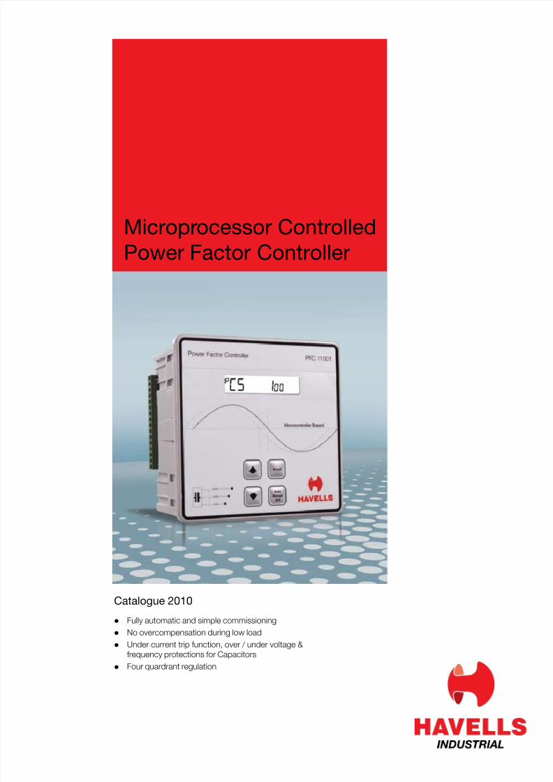
Microprocessor ControlledPower Factor Controller
Catalogue 2010
l Fully automatic and simple commissioningl No overcompensation during low loadl Under current trip unction, over / under voltage &
requency protections or Capacitorsl Four quardrant regulation
7/28/2019 634159646256874263-APFC Cat 6th july
http://slidepdf.com/reader/full/634159646256874263-apfc-cat-6th-july 2/4
Microprocessor Controlled Power Factor Controller
Compliance / StandardSpecifcation
IEC 61000-6-2, IEC 61000-6-4,
IEC 61010-1
Operating Voltage (Un): 230 V AC ± 20%; 50/60 Hz
Operating Current 50 mA – 6 A (--/5 A Current Trans ormer)
Network Type 1 Phase, 2 wire
Capacitor Steps 6, 8, 12, 14 steps (max) + 1 ALARMPower Consumption < 2 VA (Current Circui t), < 10 VA
(Voltage Circuit)
Output Contact 3 A, 750 VA
Cos Ø setting 0.8< cos Ø £ 1(Inductive)
Ambient Operating temp. -10° C, +60° C
Degree o Protection IP 54 (Front Panel)
Connection/ Installation Terminal / Flush - Mounting with rearterminals
Dimensions & 144 x 144 x 85 mm
Packing Weight 770 gm (Approx.)
CT Ratio Confgurable (max. 1000/5)
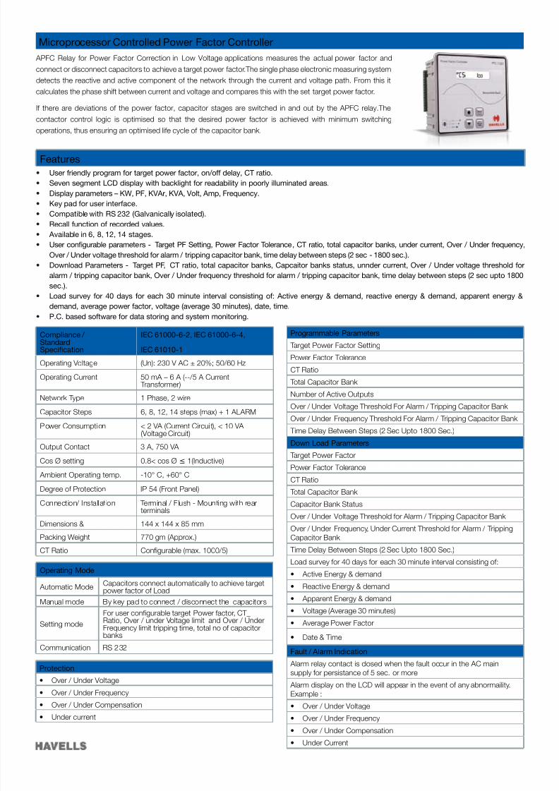
APFC Relay or Power Factor Correction in Low Voltage applications measures the actual power actor andconnect or disconnect capacitors to achieve a target power actor.The single phase electronic measuring systemdetects the reactive and active component o the network through the current and voltage path. From this itcalculates the phase shi t between current and voltage and compares this with the set target power actor.
I there are deviations o the power actor, capacitor stages are switched in and out by the APFC relay.Thecontactor control logic is optimised so that the desired power actor is achieved with minimum switchingoperations, thus ensuring an optimised li e cycle o the capacitor bank.
Protection
• Over / Under Voltage
• Over / Under Frequency• Over / Under Compensation
• Under current
Features • User riendly program or target power actor, on/o delay, CT ratio.• Seven segment LCD display with backlight or readability in poorly illuminated areas.• Display parameters – KW, PF, KVAr, KVA, Volt, Amp, Frequency.• Key pad or user inter ace.• Compatible with RS 232 (Galvanically isolated).• Recall unction o recorded values.• Available in 6, 8, 12, 14 stages.• User confgurable parameters - Target PF Setting, Power Factor Tolerance, CT ratio, total capacitor banks, under current, Over / Under requency,
Over / Under voltage threshold or alarm / tripping capacitor bank, time delay between steps (2 sec - 1800 sec.).• Download Parameters - Target PF, CT ratio, total capacitor banks, Capcaitor banks status, unnder current, Over / Under voltage threshold or
alarm / tripping capacitor bank, Over / Under requency threshold or alarm / tripping capacitor bank, time delay between steps (2 sec upto 1800sec.).
• Load survey or 40 days or each 30 minute interval consisting o : Active energy & demand, reactive energy & demand, apparent energy & demand, average power actor, voltage (average 30 minutes), date, time.
• P.C. based so tware or data storing and system monitoring.
Operating Mode
Automatic Mode Capacitors connect automatically to achieve targetpower actor o Load
Manual mode By key pad to connect / disconnect the capacitors
Setting modeFor user confgurable target Power actor, CT_Ratio, Over / under Voltage limit and Over / UnderFrequency limit tripping time, total no o capacitorbanks
Communication RS 232
Programmable Parameters
Target Power Factor Setting
Power Factor Tolerance
CT Ratio
Total Capacitor Bank
Number o Active Outputs
Over / Under Voltage Threshold For Alarm / Tripping Capacitor Bank
Over / Under Frequency Threshold For Alarm / Tripping Capacitor Bank
Time Delay Between Steps (2 Sec Upto 1800 Sec.)
Down Load Parameters
Target Power Factor
Power Factor Tolerance
CT Ratio
Total Capacitor Bank
Capacitor Bank Status
Over / Under Voltage Threshold or Alarm / Tripping Capacitor Bank
Over / Under Frequency, Under Current Threshold or Alarm / TrippingCapacitor Bank
Time Delay Between Steps (2 Sec Upto 1800 Sec.)
Load survey or 40 days or each 30 minute interval consisting o :
• Active Energy & demand
• Reactive Energy & demand
• Apparent Energy & demand
• Voltage (Average 30 minutes)
• Average Power Factor
• Date & Time
Fault / Alarm Indication
Alarm relay contact is closed when the ault occur in the AC mainsupply or persistance o 5 sec. or more
Alarm display on the LCD will appear in the event o any abnormaility.Example :• Over / Under Voltage
• Over / Under Frequency
• Over / Under Compensation
• Under Current
7/28/2019 634159646256874263-APFC Cat 6th july
http://slidepdf.com/reader/full/634159646256874263-apfc-cat-6th-july 3/4
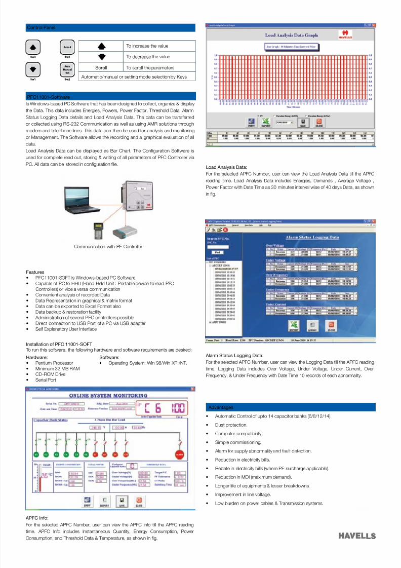
PFC11001-So twareIs Windows-based PC So tware that has been designed to collect, organize & displaythe Data. This data includes Energies, Powers, Power Factor, Threshold Data, AlarmStatus Logging Data details and Load Analysis Data. The data can be trans erredor collected using RS-232 Communication as well as using AMR solutions throughmodem and telephone lines. This data can then be used or analysis and monitoringor Management. The So tware allows the recording and a graphical evaluation o alldata.Load Analysis Data can be displayed as Bar Chart. The Confguration So tware isused or complete read out, storing & writing o all parameters o PFC Controller viaPC. All data can be stored in confguration fle.
Communication with PF Controller
Features• PFC11001-SOFT is Windows-based PC Software• Capable of PC to HHU (Hand Held Unit : Portable device to read PFC
Controllers) or vice a versa communication• Convenient analysis of recorded Data• Data Representation in graphical & matrix format• Data can be exported to Excel Format also.• Data backup & restoration facility• Administration of several PFC controllers possible• Direct connection to USB Port of a PC via USB adapter• Self Explanatory User Interface
Installation o PFC 11001-SOFT To run this so tware, the ollowing hardware and sotware requirements are desired:
Hardware: So tware:• Pentium Processor • Operating System: Win 98/Win XP /NT.• Minimum 32 MB RAM• CD-ROM Drive• Serial Port
APFC In o:For the selected APFC Number, user can view the APFC In o till the APFC readingtime. APFC Info includes Instantaneous Quantity, Energy Consumption, PowerConsumption, and Threshold Data & Temperature, as shown in fg.
Load Analysis Data:For the selected APFC Number, user can view the Load Analysis Data till the APFCreading time. Load Analysis Data includes Energies, Demands , Average Voltage ,Power Factor with Date Time as 30 minutes interval wise o 40 days Data, as shownin fg.
Alarm Status Logging Data:For the selected APFC Number, user can view the Logging Data till the APFC readingtime. Logging Data includes Over Voltage, Under Voltage, Under Current, OverFrequency, & Under Frequency with Date Time 10 records o each abnormality.
Control Panel
To increase the value
To decrease the value
Scroll To scroll the parameters
Automatic/manual or setting mode selection by Keys
Advantages
• Automatic Control of upto 14 capacitor banks (6/8/12/14).
• Dust protection.
• Computer compatibil ity.
• Simple commissioning.
• Alarm for supply abnormality and fault detection.
• Reduction in electricity bills.
• Rebate in electricity bills (where PF surcharge applicable).
• Reduction in MDI (maximum demand).
• Longer life of equipments & lesser breakdowns.
• Improvement in line voltage.
• Low burden on power cables & Transmission systems.
7/28/2019 634159646256874263-APFC Cat 6th july
http://slidepdf.com/reader/full/634159646256874263-apfc-cat-6th-july 4/4
Regional & Branch O fces:NORTH- REGIONAL OFFICES : Delhi : QRG Towers, 2D, Sector-126, Expressway, Noida-201304, Tel: 0120-4771000, Fax: 0120-4772000, Chandigarh : Tel: 0172-3934801, 3934802,Fax: 0172-3934803, Dehradun : Tel: 0135-2521025, 2521552, Haryana : Tel: 91-120 2477848 / 853, Fax: 0120-2583904 , Noida : Tel: 0120-3055609 / 3055610, Fax: 0120-3055611,Ludhiana : Tel: 0161-4676001 / 6024, Fax: 0161-46766007, Jammu:Tel:0191-2490424, Fax: 0191-2490405, Jaipur : Tel: 0141-3988210, Fax: 0141-2389024,
Lucknow: Tel: 0522-2201032, 2200938, Kanpur : Tel: Airtel: 09935533751/52/53, 0512-2690128/129/130, Fax: 0512-2692800, EAST- REGIONAL OFFICE : Kolkata : ICC Tower,5th Floor, 4 India Exchange Place, Kolkata –700 001, Tel: 033 40129851/52, Fax: 033-40127339, Bhubaneshwar : Tel: 0674-2598104, 2598105, 2598106, Fax: 0674-2598107,Guwahati : Tel: 0361-2134521, 2458923, Fax: 0361-2460355, Siliguri : Tel: 0353-2525907-3290402 (RIM), Jamshedpur : Tel: 0657-6542492, 09234369436, Patna : Tel: 0612-3244218, 2655519, Telefax: 0612-2655518 WEST- REGIONAL OFFICE : Mumbai : 302, Boston House, 3rd Floor Suren Road, CTS No. 260/261, Anheri (E)-Mumbai-400 093,
Tel: 022-67298600-603, Ahmedabad : Tel: 079-40061111, 40060738-740, Fax: 079-40060741, Indore : Tel: 0731-2572340-41, 4009998 (Airtel), Fax: 0731-2551626,Rajkot : Tel: 0281 3013289 / 3013290, Napur : Tel: 0712-2224132, 2222692, 2222029 Pune : Tel: 020-64016413/14, Raipur : Tel: 0771-4243400 / 01, Telefax: 0771-4243402,Surat : Telefax: 0261-2350137 SOUTH -REGIONAL OFFICE : Chennai : Block – 1, A & D Wing, Shakth i Towers, 7th Floor, 766, Annna Salai, Chennai – 600 002, Tel: 044 28526941-44,Fax: 044-28524326, Bangalo re : Tel: 080-39882100, 30515801 / 2 / 3 /4, Fax: 080-30515804, Coimbatore : Telefax: 0422-2305767, 2306199, 2305199, Hyderabad : Tel: 040-27533372,27533355, 27533632, 66320407/0408/6401/6402, Fax: 040-27533211, Kochi : Tel.: 0484-4099000, 2393165, 2393068, Fax: 0484-2393170, Vishakapatnam : Tel: 0891-6514339,Fax: 0891-2522547
Representative O fces :• Goa • Solapur • Gwalior • Jabalpur • Hubli • Davanagere • Gulbarga • Mysore • Trichny • Kathmandu • Sambalpur • Jalandhar • Bhopal • Calicut • Madurai • Trivandrum
Although every e ort has been made to ensure accuracy in the compilation o the technical detail within this publication,speci cations and performance data are constantly changing. Current details should, therefore, be checked with Havells Group.
Havells India Ltd.Corp Of ce: QRG Towers, 2D, Sector-126, Expressway, Noida-201304 (U.P), Ph. +91-120-4771000,Corp Of ce-II : 302, Boston House, 3rd Floor Suren Road, CTS No. 260/261, Andheri (E)-Mumbai-400 093 Ph. 022-67298600-603E-mail: [email protected], www.havells.comConsumer Care No.: 1800 11 0303 (Toll ree), 011-4166 0303 (Landline) 1800 103 1313 (All Connections)
Join us on Facebook at www. acebook.com/havells and share your ways to save the planet!
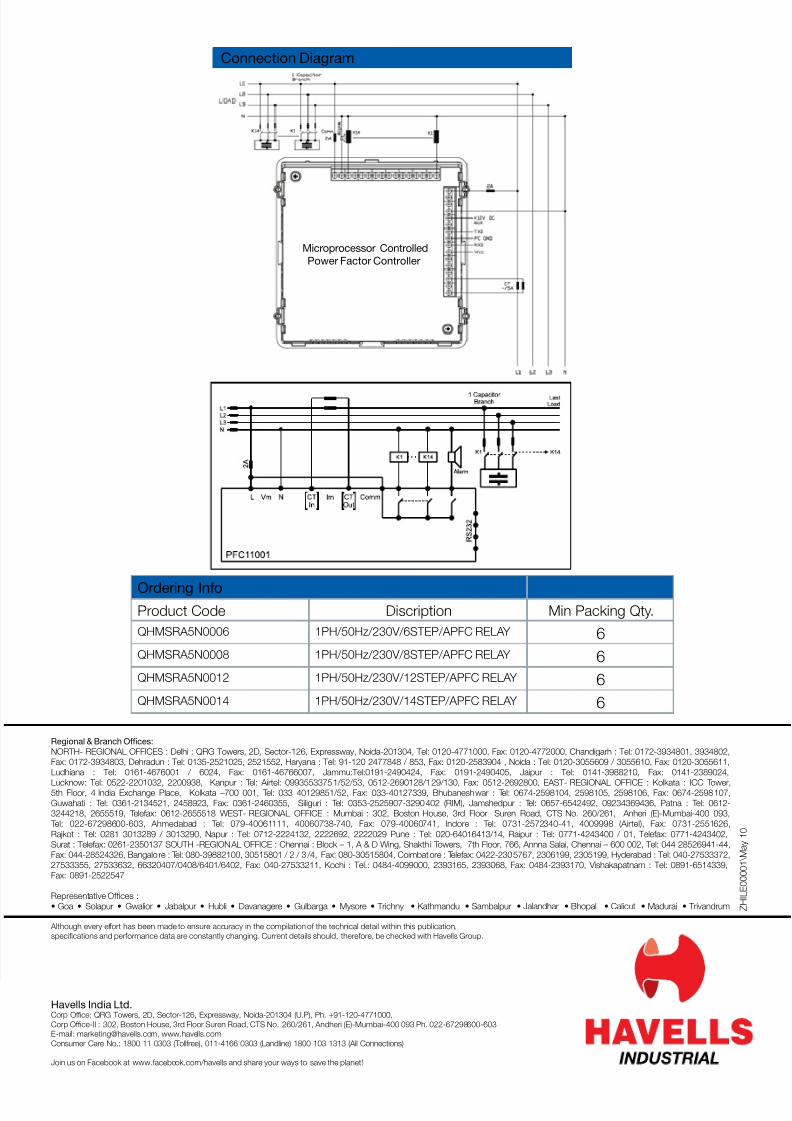
Connection Diagram
Ordering In oProduct Code Discription Min Packing Qty.QHMSRA5N0006 1PH/50Hz/230V/6STEP/APFC RELAY 6QHMSRA5N0008 1PH/50Hz/230V/8STEP/APFC RELAY 6QHMSRA5N0012 1PH/50Hz/230V/12STEP/APFC RELAY 6QHMSRA5N0014 1PH/50Hz/230V/14STEP/APFC RELAY 6
Z H I L E 0 0 0 0 1 \ M a y
1 0
Microprocessor ControlledPower Factor Controller