63-2684—01 - W7459A,B,C,D Solid State …B,C,D SOLID STATE ECONOMIZER™ LOGIC MODULE 63-2684—01...
16
PRODUCT DATA 63-2684-01 W7459A,B,C,D Solid State Economizer™ Logic Module APPLICATION The W7459 Solid State Economizer™ Logic Module is used with C7400 Solid State Enthalpy Sensors or C7660 Solid State Dry Bulb Temperature Sensors and M7405, M7415 or M8405 Damper Actuators to proportion outdoor and return air dampers for economizer control in commercial HVAC equipment. FEATURES • Operates from cooling space thermostat to provide a totally integrated control system. • Solid state control package provides improved accuracy, reliability and stability. • Combines solid state enthalpy or dry bulb changeover control, minimum damper position potentiometer (W7459A,B,D) and compressor staging relay functions. • Optional differential enthalpy control provides greater economizer savings than single enthalpy control by selecting the most economical air for cooling (return or outdoor air). • Housed in high-impact, glass-fiber reinforced plastic case to match lines of M7405, M7415, and M8405 Damper Actuators. • Enthalpy setpoint on W7459 Economizer sets combination of air temperature and humidity suitable for free cooling. • W7459A, B and D models include a built-in adjustable potentiometer to set minimum position and minimum amount of outdoor air admitted to meet minimum ventilation requirements. Terminals included for connecting an optional remote minimum position potentiometer for remote damper control. • LED on W7459 indicates free cooling is available. • W7459A mounts on M7415 Proportioning Actuator. It accepts input from discharge air temperature sensors, mixed air temperature sensors, enthalpy (or dry bulb temperature) sensors, and an optional remote minimum position potentiometer. • W7459B mounts on M7405 Proportioning Actuator. It accepts direct digital control signals from W7401/ W7411 Logic Panel, C7400 Solid State Enthalpy Sensors, or C7660 Solid State Dry Bulb Temperature Sensors and an optional remote minimum position potentiometer. • W7459C mounts on M8405A Three-Position Actuator. It accepts input from a single-pole, single-throw (spst) mixed or discharge air control and C7400 Solid State Enthalpy Sensors or C7660 Solid State Dry Bulb Temperature Sensors. • W7459D mounts on M7415 Proportioning Actuator. It accepts input from discharge air temperature sensors, mixed air temperature sensors, or enthalpy sensors and optional remote minimum damper position potentiometers. W7459D returns to mechanical cooling when outdoor air enthalpy reaches preset limits. Contents Application ........................................................................ 1 Features ........................................................................... 1 Specifications ................................................................... 2 Ordering Information ........................................................ 2 Installation ........................................................................ 3 Settings and Adjustments ................................................. 12 Operation .......................................................................... 13 Checkout and Troubleshooting ......................................... 14
Transcript of 63-2684—01 - W7459A,B,C,D Solid State …B,C,D SOLID STATE ECONOMIZER™ LOGIC MODULE 63-2684—01...

PRODUCT DATA
63-2684-01
W7459A,B,C,D Solid State Economizer™ Logic Module
APPLICATION
The W7459 Solid State Economizer™ Logic Module is used with C7400 Solid State Enthalpy Sensors or C7660 Solid State Dry Bulb Temperature Sensors and M7405, M7415 or M8405 Damper Actuators to proportion outdoor and return air dampers for economizer control in commercial HVAC equipment.
FEATURES
• Operates from cooling space thermostat to provide a totally integrated control system.
• Solid state control package provides improved accuracy, reliability and stability.
• Combines solid state enthalpy or dry bulb changeover control, minimum damper position potentiometer (W7459A,B,D) and compressor staging relay functions.
• Optional differential enthalpy control provides greater economizer savings than single enthalpy control by selecting the most economical air for cooling (return or outdoor air).
• Housed in high-impact, glass-fiber reinforced plastic case to match lines of M7405, M7415, and M8405 Damper Actuators.
• Enthalpy setpoint on W7459 Economizer sets combination of air temperature and humidity suitable for free cooling.
• W7459A, B and D models include a built-in adjustable potentiometer to set minimum position and minimum amount of outdoor air admitted to meet minimum ventilation requirements. Terminals included for connecting an optional remote minimum position potentiometer for remote damper control.
• LED on W7459 indicates free cooling is available.
• W7459A mounts on M7415 Proportioning Actuator. It accepts input from discharge air temperature sensors, mixed air temperature sensors, enthalpy (or dry bulb temperature) sensors, and an optional remote minimum position potentiometer.
• W7459B mounts on M7405 Proportioning Actuator. It accepts direct digital control signals from W7401/W7411 Logic Panel, C7400 Solid State Enthalpy Sensors, or C7660 Solid State Dry Bulb Temperature Sensors and an optional remote minimum position potentiometer.
• W7459C mounts on M8405A Three-Position Actuator. It accepts input from a single-pole, single-throw (spst) mixed or discharge air control and C7400 Solid State Enthalpy Sensors or C7660 Solid State Dry Bulb Temperature Sensors.
• W7459D mounts on M7415 Proportioning Actuator. It accepts input from discharge air temperature sensors, mixed air temperature sensors, or enthalpy sensors and optional remote minimum damper position potentiometers. W7459D returns to mechanical cooling when outdoor air enthalpy reaches preset limits.
ContentsApplication ........................................................................ 1Features ........................................................................... 1Specifications ................................................................... 2Ordering Information ........................................................ 2Installation ........................................................................ 3Settings and Adjustments ................................................. 12Operation .......................................................................... 13Checkout and Troubleshooting ......................................... 14

W7459A,B,C,D SOLID STATE ECONOMIZER™ LOGIC MODULE
63-2684—01 2
ORDERING INFORMATION
When purchasing replacement and modernization products from your TRADELINE® wholesaler or distributor, refer to the TRADELINE® Catalog or price sheets for complete ordering number.
If you have additional questions, need further information, or would like to comment on our products or services, please write or phone:
1. Your local Honeywell Automation and Control Products Sales Office (check white pages of your phone directory).2. Honeywell Customer Care
1885 Douglas Drive NorthMinneapolis, Minnesota 55422-4386
In Canada—Honeywell Limited/Honeywell Limitée, 35 Dynamic Drive, Toronto, Ontario M1V 4Z9.International Sales and Service Offices in all principal cities of the world. Manufacturing in Australia, Canada, Finland, France, Germany, Japan, Mexico, Netherlands, Spain, Taiwan, United Kingdom, U.S.A.
SPECIFICATIONS
Models: See Table 1.
Electrical Ratings (W7459/C7400):Input Voltage: 24 Vac, 50/60 Hz.Power Consumption: 5.5 VA.Relay Contact Ratings at 24 Vac:
Run: 1.5A.Inrush: 3.5A.
Temperature Ratings:Operating Ambient: -25°F to 125°F (-32°C to +52°C).Humidity: 5% to 95% RH.
Approvals:Underwriters Laboratories Inc. Flammability Rating UL94V-5V.
W7459D Maximum Outdoor Enthalpy Switching: See Table 2.
Enthalpy Input Connection (C7400):2-wire (18, 20, 22 AWG) connection.Can be mounted up to 200 ft away.
Dry Bulb Temperature Input (C7660):2-wire (18, 20, 22 AWG) connection.Can be mounted up to 200 ft away.
Dimensions: See Fig. 1.
Minimum Position Potentiometer:Resistance: 250 ohms.Setting: 0 to 100% of motor stroke.
Accessories:4074EJM 620 ohm Resistor, Jumper, and 1.2K ohmCheckout Resistor.4074EJQ Board for panel mounting W7459A,D.C7046A Discharge Air Temperature Sensor.C7150B Mixed Air Temperature Sensor.C7400 Solid State Enthalpy Sensor.C7660 Solid State Dry Bulb Temperature Sensor.T675, T6031 or T775 Remote Bulb Control for low ambient
lockout.S963B1128 Remote Minimum Position Potentiometer to pro-
vide remote control of damper position.ST6008 Energy Management Timer for occupied/unoccupied
control.
a W7459D has a high enthalpy limit and defaults to mechanical cooing when the outdoor enthalpy reaches the preset limit. Do not use a dry bulb sensor for a high temperature limit.
Table 1. W7459 Economizer Models.
ModelFor Use with
ActuatorDischarge Air
Temperature InputMinimum Position
Potentiometer AdjustmentTerminals for Remote
Minimum Damper PositionOutput Relays
W7459A M7415 C7150B or C7046A Sensor
Yes Yes 2 spdt
W7459B M7405A Direct digital control W7401/W7411 Logic Panel
Yes Yes 1 spdt
W7459C M8405 Spst control No. Minimum position adjustment is built into M8405 Actuator.
No 2 spdt
W7459Da M7415 C7150B or C7046A Sensor
Yes Yes 2 spdt
W7459A,B,C,D SOLID STATE ECONOMIZER™ LOGIC MODULE
3 63-2684—01
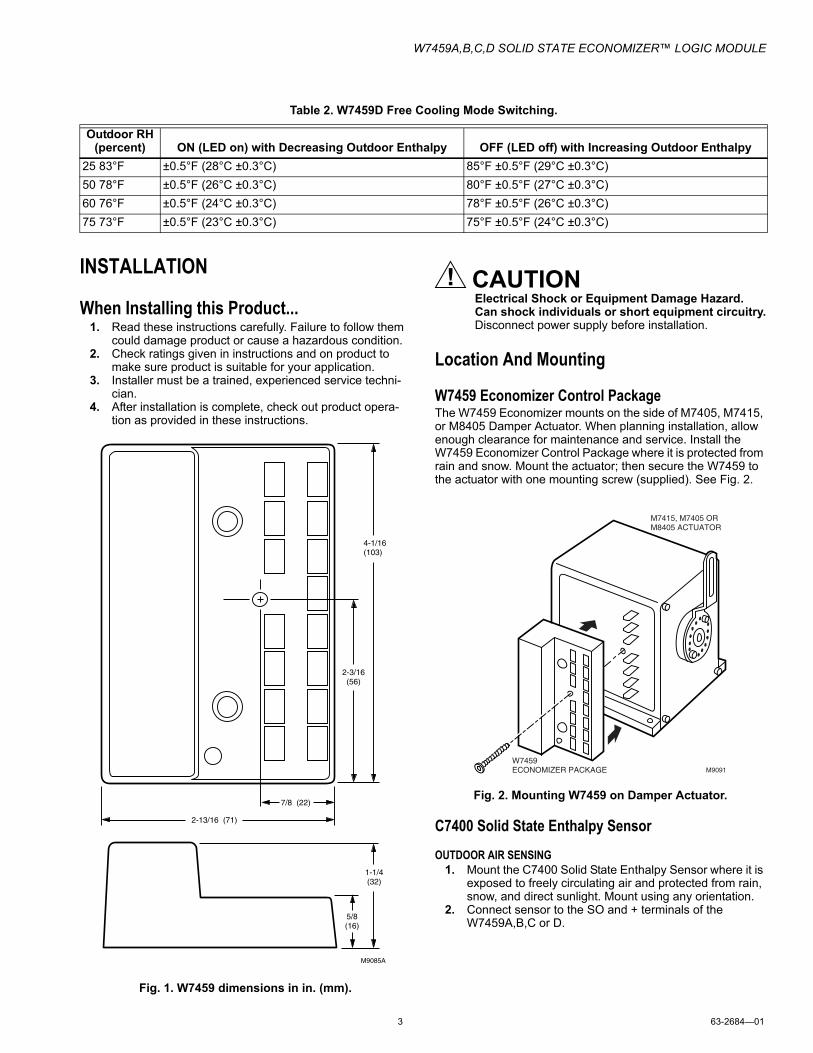
INSTALLATION
When Installing this Product...1. Read these instructions carefully. Failure to follow them
could damage product or cause a hazardous condition.2. Check ratings given in instructions and on product to
make sure product is suitable for your application.3. Installer must be a trained, experienced service techni-
cian.4. After installation is complete, check out product opera-
tion as provided in these instructions.
Fig. 1. W7459 dimensions in in. (mm).
CAUTIONElectrical Shock or Equipment Damage Hazard.Can shock individuals or short equipment circuitry.Disconnect power supply before installation.
Location And Mounting
W7459 Economizer Control PackageThe W7459 Economizer mounts on the side of M7405, M7415, or M8405 Damper Actuator. When planning installation, allow enough clearance for maintenance and service. Install the W7459 Economizer Control Package where it is protected from rain and snow. Mount the actuator; then secure the W7459 to the actuator with one mounting screw (supplied). See Fig. 2.
Fig. 2. Mounting W7459 on Damper Actuator.
C7400 Solid State Enthalpy Sensor
OUTDOOR AIR SENSING1. Mount the C7400 Solid State Enthalpy Sensor where it is
exposed to freely circulating air and protected from rain, snow, and direct sunlight. Mount using any orientation.
2. Connect sensor to the SO and + terminals of the W7459A,B,C or D.
Table 2. W7459D Free Cooling Mode Switching.
Outdoor RH (percent) ON (LED on) with Decreasing Outdoor Enthalpy OFF (LED off) with Increasing Outdoor Enthalpy
25 83°F ±0.5°F (28°C ±0.3°C) 85°F ±0.5°F (29°C ±0.3°C)
50 78°F ±0.5°F (26°C ±0.3°C) 80°F ±0.5°F (27°C ±0.3°C)
60 76°F ±0.5°F (24°C ±0.3°C) 78°F ±0.5°F (26°C ±0.3°C)
75 73°F ±0.5°F (23°C ±0.3°C) 75°F ±0.5°F (24°C ±0.3°C)
M9085A
2-3/16(56)
4-1/16(103)
7/8 (22)
5/8(16)
2-13/16 (71)
1-1/4(32)
M9091W7459 ECONOMIZER PACKAGE
M7415, M7405 OR M8405 ACTUATOR

W7459A,B,C,D SOLID STATE ECONOMIZER™ LOGIC MODULE
63-2684—01 4
RETURN AIR SENSING1. For differential enthalpy control, mount a second C7400
Solid State Enthalpy Sensor in the return air duct.2. Connect sensor to the SR and + terminals of the
W7459A,B,C or D.
C7660 Solid State Dry Bulb Temperature Sensor
IMPORTANTDo not use a C7660 with the W7459D or in a differen-tial dry bulb application. Differential applications should only use enthalpy sensors.
OUTDOOR AIR SENSING1. Mount the C7660 Solid State Dry Bulb Sensor where it is
exposed to freely circulating air and protected from rain, snow, and direct sunlight.
NOTE: Mount in any orientation to scoop the maximum amount of air into the device. Make sure the air flow-ing into the inlet ports is linear.
2. Connect sensor to the SO and + terminals of the W7459A,B, or C.
RETURN AIR SENSING1. For differential control, use enthalpy only and mount a
C7400 enthalpy sensor in the outdoor and return air duct.
2. Connect sensor to the SR and + terminals of the W7459A,B, or C.
NOTE: See Fig. 3 for typical organization of a W7459 Econo-mizer System.
WIRING
CAUTIONElectrical Shock or Equipment Damage Hazard.Can shock individuals or short equipment circuitry.Disconnect power supply before installation.
Refer to Fig. 4 through 10 for typical wiring diagrams:
Fig. 3. Location of C7400 Outdoor and Return Air Sensors, C7150 Mixed Air Sensor, and C7046 Discharge Air Sensor in a W7459 Economizer System.
DISCHARGEAIR SENSOR
C7046ADIRECT EXPANSIONCOIL
M7415 ACTUATORWITH W7459AECONOMIZERCONTROL PACKAGE
C7400
ENTHALPYSENSOR
C7400 ENTHALPYSENSOR
RETURN AIR
OUTDOORAIR
C7150B
MIXED AIRSENSOR
SPACE THERMOSTATOR T7400/W7400PROGRAMMABLESINGLE ZONESYSTEM
FOR DIFFERENTIAL ENTHALPY, TWO C7400 ENTHALPY SENSORS ARE CONNECTED TO W7459 ECONOMIZER CONTROL. ONE IS MOUNTED IN RETURN AIR; THE OTHER IS MOUNTED IN OUTDOOR AIR. DIFFERENTIAL ENTHALPY CONTROL PROVIDES GREATERENERGY SAVINGS THAN SINGLE ENTHALPY.
M10119
1
1
1
W7459A,B,C,D SOLID STATE ECONOMIZER™ LOGIC MODULE
5 63-2684—01
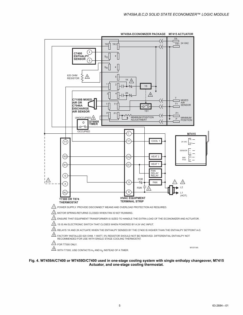
Fig. 4. W7459A/C7400 or W7459D/C7400 used in one-stage cooling system with single enthalpy changeover, M7415 Actuator, and one-stage cooling thermostat.
L1 (HOT)
L2
FDR
FDR
FAN
FANDELAYRELAY
HEAT 1
HEAT 2
COOL 1
HVAC EQUIPMENTTERMINAL STRIP
POWER SUPPLY. PROVIDE DISCONNECT MEANS AND OVERLOAD PROTECTION AS REQUIRED.
MOTOR SPRING-RETURNS CLOSED WHEN FAN IS NOT RUNNING.
ENSURE THAT EQUIPMENT TRANSFORMER IS SIZED TO HANDLE THE EXTRA LOAD OF THE ECONOMIZER AND ACTUATOR.
1S IS AN ELECTRONIC SWITCH THAT CLOSES WHEN POWERED BY A 24 VAC INPUT.
RELAYS 1K AND 2K ACTUATE WHEN THE ENTHALPY SENSED BY THE C7400 IS HIGHER THAN THE ENTHALPY SETPOINT A-D.
FACTORY INSTALLED 620 OHM, 1 WATT, 5% RESISTOR SHOULD NOT BE REMOVED. DIFFERENTIAL ENTHALPY NOT RECOMMENDED FOR USE WITH SINGLE STAGE COOLING THERMOSTAT.
FOR T7300 ONLY.
WITH T7300, USE CONTACTS A1 AND A2 INSTEAD OF A TIMER.M10114A
T7300 OR T874THERMOSTAT
T1
P1P1P
T1
1
3 4
2
5
2K
S
1
1
2
3
4
6
TR TR1
SO
SR
+
+
TR
M7415 ACTUATORW7459A ECONOMIZER PACKAGE
+
C
G
W1
Y1
R
W2
RC
G
X
W1
Y1
W2
C7400ENTHALPY SENSOR
UNOCCUPIED
OCCUPIED
ST6008 TIMER
3
2
51K
4
5
T
6
7
7
8
8 P
T
1S
1S1
MINIMUM POSITIONADJUSTMENT
TR1
MINIMUMPOSITION
MIXEDAIRSENSOR
24 VAC
C7150B MIXED AIR OR C7046ADISCHARGE AIR SENSOR
M7415
TR
TR1
T1
P1P
24 VAC
SENSOR
MINPOS
T
620 OHMRESISTOR
W7459A,B,C,D SOLID STATE ECONOMIZER™ LOGIC MODULE
63-2684—01 6
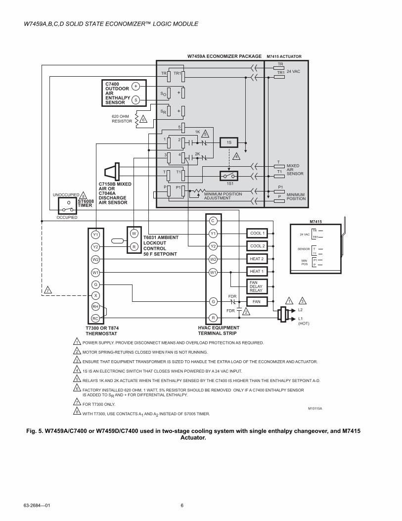
Fig. 5. W7459A/C7400 or W7459D/C7400 used in two-stage cooling system with single enthalpy changeover, and M7415 Actuator.
L1 (HOT)
L2
FDR
FDR
FAN
FANDELAYRELAY
HEAT 1
HEAT 2
COOL 1
HVAC EQUIPMENTTERMINAL STRIP
POWER SUPPLY. PROVIDE DISCONNECT MEANS AND OVERLOAD PROTECTION AS REQUIRED.
MOTOR SPRING-RETURNS CLOSED WHEN FAN IS NOT RUNNING.
ENSURE THAT EQUIPMENT TRANSFORMER IS SIZED TO HANDLE THE EXTRA LOAD OF THE ECONOMIZER AND ACTUATOR.
1S IS AN ELECTRONIC SWITCH THAT CLOSES WHEN POWERED BY A 24 VAC INPUT.
RELAYS 1K AND 2K ACTUATE WHEN THE ENTHALPY SENSED BY THE C7400 IS HIGHER THAN THE ENTHALPY SETPOINT A-D.
FACTORY INSTALLED 620 OHM, 1 WATT, 5% RESISTOR SHOULD BE REMOVED ONLY IF A C7400 ENTHALPY SENSOR IS ADDED TO SR AND + FOR DIFFERENTIAL ENTHALPY.
FOR T7300 ONLY.
WITH T7300, USE CONTACTS A1 AND A2 INSTEAD OF S7005 TIMER. M10115A
T7300 OR T874THERMOSTAT
T1
P1P1P
T1
1
3 4
2
5
2K
S
1
1
2
3
4
6
TR TR1
SO
SR
+
+
TR
M7415 ACTUATORW7459A ECONOMIZER PACKAGE
+
C
G
W1
Y1
R
W2
RC
G
X
W1
Y1
Y2
W2
C7400OUTDOORAIR ENTHALPY SENSOR
UNOCCUPIED
OCCUPIED
ST6008TIMER
3
2
51K
COOL 2Y2
4
5
T
6
7
7
8
8 P
T
1S
1S1
MINIMUM POSITIONADJUSTMENT
TR1
MINIMUMPOSITION
MIXEDAIRSENSOR
24 VAC
C7150B MIXED AIR OR C7046ADISCHARGE AIR SENSOR
M7415
TR
TR1
T1
P1P
24 VAC
SENSOR
MINPOS
T
620 OHMRESISTOR
W
R
T6031 AMBIENT LOCKOUT CONTROL 50 F SETPOINT
RH

W7459A,B,C,D SOLID STATE ECONOMIZER™ LOGIC MODULE
7 63-2684—01
Fig. 6. W7459A/C7400 or W7459D/C7400 used in two-stage cooling system with single enthalpy changeover, M7415 Actuator, and T775 Thermostat.
L1 (HOT)
L2
FAN
COOL 1
HVAC EQUIPMENTTERMINAL STRIP
POWER SUPPLY. PROVIDE DISCONNECT MEANS AND OVERLOAD PROTECTION AS REQUIRED.
MOTOR SPRING-RETURNS CLOSED WHEN FAN IS NOT RUNNING.
ENSURE THAT EQUIPMENT TRANSFORMER IS SIZED TO HANDLE THE EXTRA LOAD OF THE ECONOMIZER AND ACTUATOR.
1S IS AN ELECTRONIC SWITCH, WHICH CLOSES WHEN POWERED BY A 24 VAC INPUT.
RELAYS 1K AND 2K ACTUATE WHEN THE ENTHALPY SENSED BY THE C7400 IS HIGHER THAN THE ENTHALPY SETPOINT A-D.
FACTORY INSTALLED 620 OHM, 1 WATT, 5% RESISTOR SHOULD BE REMOVED ONLY IF A C7400 ENTHALPY SENSOR IS ADDED TO SR AND + FOR DIFFERENTIAL ENTHALPY.
T775 REQUIRES A MINIMUM OF THREE RELAY OUTPUTS: TWO FOR COOLING AND ONE FOR FAN CONTROL.A MAXIMUM OF ONE STAGE OF HEATING IS POSSIBLE WHEN THE SYSTEM IS WIRED IN THIS FASHION. M11680A
T1
P1P1P
T1
1
3 4
2
5
2K
S
1
1
2
3
4
6
TR TR1
SO
SR
+
+
TR
M7415 ACTUATORW7459A ECONOMIZER PACKAGE
+
C
G
Y1
R
C7400OUTDOORAIR ENTHALPY SENSOR
3
2
51K
COOL 2Y2
4
5
T
6
7
7
P
T
1S
1S1
MINIMUM POSITIONADJUSTMENT
TR1
MINIMUMPOSITION
MIXEDAIRSENSOR
24 VAC
C7150B MIXED AIR OR C7046ADISCHARGE AIR SENSOR
M7415
TR
TR1
T1
P1P
24 VAC
SENSOR
MINPOS
T
620 OHMRESISTOR
W
R
T6031 AMBIENT LOCKOUT CONTROL 50 F SETPOINT
NOCOM
NC
NCCOM
NO
NCCOMNO
T775 CONTROLLER
UNOCCUPIED
OCCUPIED
ST6008TIMER

W7459A,B,C,D SOLID STATE ECONOMIZER™ LOGIC MODULE
63-2684—01 8
Fig. 7. W7459A/C7400 or W7459D/C7400 used in one-stage cooling system with differential enthalpy changeover, and M7415 Actuator.
L1 (HOT)
L2
FDR
FDR
FAN
FANDELAYRELAY
HEAT 1
HEAT 2
COOL 1
HVAC EQUIPMENTTERMINAL STRIP
W
R
POWER SUPPLY. PROVIDE DISCONNECT MEANS AND OVERLOAD PROTECTION AS REQUIRED.
MOTOR SPRING-RETURNS CLOSED WHEN FAN IS NOT RUNNING.
ENSURE THAT EQUIPMENT TRANSFORMER IS SIZED TO HANDLE THE EXTRA LOAD OF THE ECONOMIZER AND ACTUATOR.
1S IS AN ELECTRONIC SWITCH THAT CLOSES WHEN POWERED BY A 24 VAC INPUT.
RELAYS 1K AND 2K ACTUATE WHEN THE OUTDOOR AIR ENTHALPY IS HIGHER THAN THE ENTHALPY SETPOINT A-D.
FACTORY INSTALLED 620 OHM, 1 WATT, 5% RESISTOR SHOULD BE REMOVED ONLY WHEN A C7400 ENTHALPY SENSOR IS ADDED TO SR AND + FOR DIFFERENTIAL ENTHALPY.
FOR T7300 ONLY.
WITH T7300, USE CONTACTS A1 AND A2 INSTEAD OF A TIMER.
M3864B
T7300 OR T874THERMOSTAT
T1
P1P1P
T1
1
3 4
2
2K
S
C7400OUTDOORAIRENTHALPYSENSOR
C7400RETURNAIRENTHALPYSENSOR
1
1
2
3
4
TR TR1
SO
SR
+
+
TR
M7415 ACTUATORW7459A ECONOMIZER PACKAGE
+
C
G
W1
Y1
Y2
R
W2
S
+
RC
G
X
W1
Y1
Y2
W2
RH
T6031 AMBIENT LOCKOUT CONTROL 50 F SETPOINT
UNOCCUPIED
OCCUPIED
ST6008TIMER
3
2
5
5
6
1K
4
5
T
6
7
7
8
8 P
T
1S
1S1
MINIMUM POSITIONADJUSTMENT
TR1
MINIMUMPOSITION
MIXEDAIR SENSOR
C7150B MIXEDAIR ORC7046A DISCHARGE AIR SENSOR
24 VAC

W7459A,B,C,D SOLID STATE ECONOMIZER™ LOGIC MODULE
9 63-2684—01
Fig. 8. W7459A/C7400 or W7459D/C7400 used in T7400/W7400 System with M7415 Actuator.
L1 (HOT)
L2
FDR
3K1
GND
FAN
FANDELAYRELAY
HEAT 1
HEAT 2
COOL 1
HVAC EQUIPMENTTERMINAL STRIP
W
R
14 23 R
POWER SUPPLY. PROVIDE DISCONNECT MEANS AND OVERLOAD PROTECTION AS REQUIRED.
MOTOR SPRING-RETURNS CLOSED WHEN FAN IS NOT RUNNING.
ENSURE THAT EQUIPMENT TRANSFORMER IS SIZED TO HANDLE THE EXTRA LOAD OF THE ECONOMIZER AND ACTUATOR.
1S IS AN ELECTRONIC SWITCH THAT CLOSES WHEN POWERED BY A 24 VAC INPUT.
RELAYS 1K AND 2K ACTUATE WHEN THE ENTHALPY SENSED BY THE C7400 IS HIGHER THAN THE ENTHALPY SETPOINT A-D.
USE R8222N WITH PILOT DUTY CONTACTS FOR 3K. CONTACTS 3K1, 3K2 MAKE WHEN ENTHALPY IS BELOW SETPOINTAND ECONOMIZER IS USED FOR FIRST STAGE OF COOLING.
FACTORY INSTALLED 620 OHM, 1 WATT, 5% RESISTOR SHOULD BE REMOVED ONLY WHEN A C7400 ENTHALPY SENSOR IS ADDED TO SR AND + FOR DIFFERENTIAL ENTHALPY.
M10117A
T7400 THERMOSTATT7400/W7400 SYSTEM
T1
P1P1P
T1
1
3 4
2
5
2K
S
C7400ENTHALPYSENSOR
1
1
2
3
4
TR TR1
SO
SR
+
+
TR
M7415 ACTUATORW7459A ECONOMIZER PACKAGE
+
C
G
W1
Y1
Y2
R
W2
T6031 LOCKOUT 50 F SETPOINT
3
2
6
5
7
61K
COOL 2
4
5
T
6
6
7
P
T
1S
1S1
MINIMUM POSITIONADJUSTMENT
TR1
MINIMUMPOSITION
MIXEDAIR SENSOR
C7150B MIXEDAIR ORC7046A DISCHARGE AIR SENSOR
T7400B ONLY;T7047C1025 ORT7022A1010REMOTE SENSOR
W7400 CONTROL MODULE
620 OHMRESISTOR
3K RELAY
TR
TR
RHRC
4
3
2
1
24 VAC
3K2
T7400
A
COM
B
ECONO.AUXRELAY
ENTHALPYSWITCH
6
5
RC G
RH W1
W2
Y1
Y2
RC
1
WALLPLATE OR Q7400 SUBBASE
24 VAC

W7459A,B,C,D SOLID STATE ECONOMIZER™ LOGIC MODULE
63-2684—01 10
Fig. 9. W7459B/C7400 used in two-stage cooling system with single enthalpy changeover, and M7405 Actuator.
L1 (HOT)L2
M7405
TR
TR1
M3
M1
P1P
24 VAC
W7401
MINPOS
M2
R
C
G
W1
W2
Y1
Y2
RC
TR
G
W1
W2
Y1
Y2
T
T1
6
M1
FDR
FDR
FAN
FANDELAYRELAY
HEAT 1
HEAT 2
COOL 1
COOL 2
HVAC EQUIPMENTTERMINAL STRIP
W7401 LOGICPANEL
TR
RH
1
2
3
4
M2
M3
5
POWER SUPPLY. PROVIDE DISCONNECT MEANS AND OVERLOAD PROTECTION AS REQUIRED.
FACTORY INSTALLED 620 OHM, 1 WATT, 5% RESISTOR SHOULD BE REMOVED ONLY IF A C7400 ENTHALPY SENSOR IS ADDED TO SR AND + FOR DIFFERENTIAL ENTHALPY.
RELAY 1K ACTUATES WHEN THE ENTHALPY SENSED BY THE C7400 IS HIGHER THAN THE ENTHALPY SETPOINT A-D. M3863
T7400 PROGRAMABLETHERMOSTAT
C7046ADISCHARGE AIR LOW LIMIT SENSOR
24 VAC
P1
P
M2
M1
M3
MINIMUMPOSITION
24 VAC
MINIMUM POSITIONADJUSTMENT
P1P
M2 M1
M3
2 1
3
1K
S
C7400ENTHALPYSENSOR
620 OHMRESISTOR
1
1
2
3
2
3
TR TR1
SO
SR
+
+
TR1
TR
M7405 ACTUATORW7459B ECONOMIZER PACKAGE
1
2
3
4
+

W7459A,B,C,D SOLID STATE ECONOMIZER™ LOGIC MODULE
11 63-2684—01
Fig. 10. W7459C/C7400 used in two-stage cooling system with differential enthalpy changeover, and M8405 Actuator.
Optional Applications
Remote Minimum Position ControlRemote control of outdoor air dampers is desirable when potential exists for temporary additional ventilation. The potentiometer in W7459 controls damper minimum position.
Adding S963B1128 Remote Manual Potentiometer allows occupants to open dampers beyond minimum position for additional ventilation. Connect potentiometer as shown in Fig. 11.
L1 (HOT)
L2
M8405
T
D
APPLY 24VAC T-XFOR MIN POSNT-D FOR MAX POSN
FDR
FDR
FAN
FANDELAYRELAY
HEAT 1
HEAT 2
COOL 1
COOL 2
HVAC EQUIPMENTTERMINAL STRIP
W
R
POWER SUPPLY. PROVIDE DISCONNECT MEANS AND OVERLOAD PROTECTION AS REQUIRED.
MOTOR SPRING-RETURNS CLOSED WHEN FAN IS NOT RUNNING.
ENSURE THAT EQUIPMENT TRANSFORMER IS SIZED TO HANDLE THE EXTRA LOAD OF THE ECONOMIZER AND ACTUATOR.
RELAYS 1K AND 2K ACTUATE WHEN THE ENTHALPY SENSED BY THE C7400 IS HIGHER THAN THE ENTHALPY SETPOINT A-D.
FACTORY INSTALLED 620 OHM, 1 WATT, 5% RESISTOR SHOULD BE REMOVED ONLY IF A C7400 ENTHALPY SENSOR IS ADDED TO SR AND + FOR DIFFERENTIAL ENTHALPY.
FOR T7300 ONLY.
TR1 IS HOT ON W7459C. TR1 IS GROUND ON ALL OTHER MODELS OF W7459. M29167
T7300 OR T874THERMOSTAT
X
DD6
X
1
3 4
5
2
2K
S
C7400OUTDOORSENSOR
1
1
2
3
4
TR TR1
SO
SR
+
+
T
M8405ACTUATORW7459C ECONOMIZER PACKAGE
+
C
G
W1
Y1
Y2
R
W2
WR
SC7400RETURNSENSOR +
RC
G
X
W1
Y1
Y2
W2
RH
T675/T6031 MIXED AIR CONTROL 55°F SETPOINT
T6031 AMBIENT LOCKOUT CONTROL 50°F SETPOINT
UNOCCUPIED
OCCUPIED
ST6008TIMER
3
2
5
1K
4
5
6
6
MAX
SWSET
MIN
X
7
7

W7459A,B,C,D SOLID STATE ECONOMIZER™ LOGIC MODULE
63-2684—01 12
Fig. 11. S963B1128 Remote Minimum Position Potentiometer used with W7459 for remote damper
control.
SETTINGS AND ADJUSTMENTS
Potentiometers with screwdriver adjustment slots, located on face of device, provide adjustments for minimum damper position and enthalpy changeover. See Fig. 12.
Fig. 12. Location of enthalpy setpoint potentiometer, minimum position potentiometer and LED.
Adjusting Minimum Damper PositionMinimum position potentiometer keeps outdoor air damper from closing completely during system operation to provide ventilation.
Minimum Position Adjustment W7459A and W7459D
1. Disconnect mixed air sensor from terminals T and T1.2. Make sure either factory-installed jumper is in place
across terminals P and P1 or if remote damper posi-tioner is required, that it is wired according to Fig. 11 and turned fully clockwise.
3. Connect 24 Vac across terminals TR and TR1.4. Adjust potentiometer on face of W7459 with screwdriver
to desired minimum position.
W7459B1. Make sure either the factory-installed jumper is in place
across terminals P and P1 or if remote damper posi-tioner is required, that it is wired according to Fig. 11 and turned fully clockwise.
2. Connect jumper across terminals M1 and M3.
IMPORTANTDo not contact or connect jumper to M2. If M2 is jum-pered to M1, the motor will not respond to the control-ler.
3. Connect 24 Vac across terminals TR and TR1.4. Adjust potentiometer on face of W7459 with screwdriver
to desired minimum position.
W7459C1. Connect 24 Vac at terminals TR and X.
NOTE: Ensure that terminal D is not connected.
2. Adjust thumbwheel on motor for desired minimum posi-tion.
Outdoor Enthalpy Changeover SetpointThe outdoor enthalpy changeover setpoint is used to return the outdoor air damper to minimum position when enthalpy rises above setpoint. Enthalpy setpoint scale markings, located on W7459, are A, B, C, and D; see Fig. 13 for corresponding control point. The factory-installed 620 ohm jumper must be in place across terminals SR and +.
Differential Enthalpy Changeover SettingDifferential enthalpy control uses two C7400 Solid State Enthalpy Sensors connected to one W7459 Economizer Control. The economizer compares outdoor air to the return air instead of to a set point (as with single enthalpy). Turn enthalpy setpoint potentiometer fully clockwise [cw arrow] to D setting. The economizer selects the lower enthalpy air (return or outdoor) for cooling; for example, when outdoor air has lower enthalpy than return air, the outdoor air damper opens to bring in outdoor air for free cooling.
M10116A
P1P
W7459A,B,D ECONOMIZER PACKAGE
R
MINIMUM POSITIONADJUSTMENT
W B
CWCLOSE
CCWOPEN
S963B1128 REMOTEMINIMUM POSITIONPOTENTIOMETER
135 OHM
OPEN
1
1M9098B
ENTHALPYCHANGEOVERSETPOINT
MINIMUM DAMPERPOSITION SETTING
LED LIGHTSWHEN OUTDOOR AIR IS SUITABLE FOR FREE COOLING
MINIMUM DAMPER POSITION ADJUSTMENT IS PRESENT ONLY ON W7459A,D MODELS.

W7459A,B,C,D SOLID STATE ECONOMIZER™ LOGIC MODULE
13 63-2684—01
Fig. 13. W7459/C7400 performance characteristics for enthalpy changeover settings.
High Enthalpy LimitW7459D Economizer Logic Module has a high outdoor air enthalpy limit feature when used in differential enthalpy mode. The limit feature prevents using high enthalpy outdoor air when return air enthalpy is higher than outdoor air. See Table 2 in the Specifications section.
OPERATION
Integrated Economizer System Single (Outdoor) EnthalpyThe purpose of an economizer is to use outdoor air for cooling whenever possible, to reduce compressor operation. The W7459 Economizer System, when wired as shown in Fig. 4 through 10, responds to a signal from the cooling thermostat. This system uses the C7400 Solid State Enthalpy Changeover Sensor or the C7660 Solid State Dry Bulb Temperature Sensor. The C7400 responds to both dry bulb temperature and
humidity, allowing use of outdoor air at higher temperatures for free cooling when humidity is low. The C7660 responds to only dry bulb temperature and should be used only in dry, arid climates and in single enthalpy applications.
The economizer functions as a true first stage of cooling and provides maximum fuel economy during the cooling cycle. The economizer is automatically locked out during heating. It holds the outdoor air damper at the minimum position setting.
On a call for cooling by the space thermostat, the system operates as follows:
OUTDOOR AIR ENTHALPY IS BELOW SETPOINT1. The outdoor air damper is proportioned open (and the
return air damper is proportioned closed) to maintain between 50°F and 56°F at the mixed/discharge air sen-sor.
2. During economizer operation, mechanical cooling is operated by the second stage of cooling on the space thermostat.
CONTROLCURVE
ABCD
CONTROL POINTAPPROX. °F (°C)
AT 50% RH
73 (23)70 (21)67 (19)63 (17)
12
14
16
18
20
22
24
26
28
30
32
34
36
38
40
42
44
46
90100
8070
60
50
40
30
20
10
ENTHALP
Y—BTU
PER P
OUND D
RY AIR
85(29)
90(32)
95(35)
100(38)
105(41)
110(43)
35(2)
35(2)
40(4)
40(4)
105(41)
110(43)
45(7)
45(7)
50(10)
50(10)
55(13)
55(13)
60(16)
60(16)
65(18)
65(18)
70(21)
70(21)
75(24)
75(24)
80(27)
80(27)
85(29)
90(32)
95(35)
100(38)
APPROXIMATE DRY BULB TEMPERATURE—°F (°C)
A
A
B
B
C
C
D
D
M11681
RE
LATI
VE
HU
MID
ITY
(%)
1
1
HIGH LIMIT CURVE FOR W7459D.

W7459A,B,C,D SOLID STATE ECONOMIZER™ LOGIC MODULE
63-2684—01 14
OUTDOOR AIR ENTHALPY IS ABOVE SETPOINT1. The outdoor air damper closes to its minimum position.2. A call for cooling from the space thermostat brings on
mechanical cooling.3. During the unoccupied period, the actuator spring return
moves the outdoor air damper to the fully closed posi-tion.
NOTE: See Fig. 3 for representative locations of economizer system devices.
CHECKOUT AND TROUBLESHOOTING
Check the W7459 for proper operation. Table 3 through 5 describe how to simulate various environmental conditions. Make necessary minor adjustments to the minimum position until desired operation is obtained.
If the economizer system does not operate properly, check individual components of the system according to the instructions provided with each device.
If the other components operate properly when disconnected from the W7459, but the system (as a whole) does not, replace the W7459.
CAUTIONEquipment Damage Hazard.Excessive force can damage controls.Use a small screwdriver when adjusting enthalpy changeover and minimum damper position controls.
To check motor, jumper T to T1 to bypass the mixed air sensor.
Table 3. Troubleshooting procedure for W7459A or W7459D Economizer Installed on M7415 Actuator.
Checkout Procedure Proper Response
1. a. Disconnect power at TR and TR1. —
b. Disconnect Jumper P to P1.
c. Jumper TR to 1.
d. Jumper T1 to T.
e. If connected, remove C7400 Solid State Enthalpy Sensor from terminals SO and +. Ensure factoryinstalled 620 ohm resistor is connected to terminals SR and +.
LED is off.
f. Apply power (24 Vac) to terminals TR and TR1. Motor is in closed position.
2. a. Disconnect factory-installed 620 ohm resistor from terminals SR and +.
LED turns on (on A model only, for D model, go to step 3)Motor drives toward open.
3. a. To simulate high and low enthalpy (single enthalpy sensor), reconnect factory-installed 620 ohm resistor from terminals SR and +. Connect 1.2K ohm 4074EJM Checkout Resistor across terminals SO and +.
—
b. Turn enthalpy setpoint potentiometer to “A”. LED turns on, indicating low enthalpy. Motor drives toward open.
c. Turn enthalpy setpoint potentiometer to “D”. LED turns off, indicating high enthalpy. Motor drives toward closed.
d. Disconnect the 1.2K ohm checkout resistor. —
4. a. To verify sensor operation, reconnect the + lead of outdoor enthalpy sensor to the + terminal of W7459.
b. Connect a DC milliammeter between terminal SO of the W7459A and terminal S of the enthalpy sensor. See Fig. 14 (positive meter lead to terminal S of the enthalpy sensor).
Milliammeter indication is between 3 and 25 mA if sensor is operating properly. If milliammeter indicates zero, the sensor may be wired backward.
c. When using differential enthalpy, check the return air enthalpy sensor by connecting a DC milliammeter between terminal SR of the W7459A and terminal S of the return air enthalpy sensor. (Positive meter lead to terminal S of the enthalpy sensor.)
Milliammeter indication is between 3 and 25 mA if sensor is operating properly. If milliammeter indicates zero, the sensor may be wired backward.

W7459A,B,C,D SOLID STATE ECONOMIZER™ LOGIC MODULE
15 63-2684—01
Fig. 14. Meter location for checkout and troubleshooting.
1
1
2
2
M9097
ENTHALPY CHANGEOVERSETPOINT
LED LIGHTS WHENOUTDOOR AIR IS SUITABLE FOR FREE COOLING
INSERT DC MILLIAMMETER BETWEEN SO AND S FOR CHECKOUT AND TROUBLESHOOTING.
JUMPER USED FOR SINGLE ENTHALPY CONTROL.
TR TR1
A
B C
DSO
SR
+
+
+
C7400
620 OHMJUMPER
DC MILLIAMMETER
W7459
S
+
Table 4. Troubleshooting procedure for W7459B Economizer installed on M7405 Actuator.
Checkout ProcedureProper Response
1. a. Disconnect power at TR and TR1. —
b. Disconnect Jumper P to P1.
c. Jumper M1 to 3.
d. Jumper M2 to 2. M3 remains unconnected.
e. If connected, remove C7400 Solid State Enthalpy Sensor from terminals SO and +. Ensure factoryinstalled 620 ohm resistor is connected to terminals SR and +.
LED is off.
f. Apply power (24 Vac) to terminals TR and TR1. Motor is in closed position.
2. a. Disconnect factory-installed 620 ohm resistor from terminals SR and +.
LED turns on.Motor drives toward open.
3. a. To simulate high and low enthalpy (single enthalpy sensor), reconnect factory-installed 620 ohm resistor from terminals SR and +. Connect 1.2K ohm 4074EJM Checkout Resistor across terminals SO and +.
—
b. Turn enthalpy setpoint potentiometer to A. LED turns on, indicating low enthalpy. Motor drives toward open.
c. Turn enthalpy setpoint potentiometer to D. LED turns off, indicating high enthalpy. Motor drives toward closed.
d. Disconnect the 1.2K ohm checkout resistor. —
4. a. To verify sensor operation, reconnect the + lead of outdoor enthalpy sensor to the + terminal of W7459.
—
b. Connect a DC milliammeter between terminal SO of the W7459B and terminal S of the enthalpy sensor. See Fig. 14 (positive meter lead to terminal S of the enthalpy sensor).
Milliammeter indication is between 3 and 25 mA if sensor is operating properly.If milliammeter indicates zero, the sensor may be wired backward.
c. When using differential enthalpy, check the return air enthalpy sensor by connecting a DC milliammeter between terminal SR of the W7459B and terminal S of the return air enthalpy sensor. (Positive meter lead to terminal S of the enthalpy sensor.)
Milliammeter indication is between 3 and 25 mA if sensor is operating properly.If milliammeter indicates zero, the sensor may be wired backward.

Automation and Control Solutions
Honeywell International Inc. Honeywell Limited-Honeywell Limitée
1985 Douglas Drive North 35 Dynamic Drive
Golden Valley, MN 55422 Toronto, Ontario M1V 4Z9
customer.honeywell.com
W7459A,B,C,D SOLID STATE ECONOMIZER™ LOGIC MODULE
® U.S. Registered Trademark© 2009 Honeywell International Inc.63-2684—01 M.S. 02-09
Table 5. Troubleshooting procedure for W7459C Economizer installed on M8405 Actuator.
Checkout Procedure Proper Response
1. a. Disconnect power at TR and TR1. —
b. Disconnect wires from terminals 6, X and D.
c. Jumper TR1 to 1.
d. Jumper 6 to D.
e. If connected, remove C7400 Solid State Enthalpy Sensor fromterminals SO and +. Ensure factoryinstalled 620 ohm resistor is connected to terminals SR and +.
LED is off.
f. Apply power (24 Vac) to terminals TR and TR1. Motor is in closed position.
2. a. Disconnect factory-installed 620 ohm resistor from terminals SRand +.
LED turns on. Motor drives toward open.
3. a. To simulate high and low enthalpy (single enthalpy sensor),reconnect factory-installed 620 ohm resistor from terminals SR and +. Connect 1.2K ohm 4074EJM Checkout Resistor across terminals SO and +.
—
b. Turn enthalpy setpoint potentiometer to A. LED turns on, indicating low enthalpy. Motor drives toward open.
c. Turn enthalpy setpoint potentiometer to D. LED turns off, indicating high enthalpy. Motor drives toward closed.
d. Disconnect the 1.2K ohm checkout resistor. —
4. a. To verify sensor operation, reconnect the + lead of outdoorenthalpy sensor to the + terminal of W7459.
—
b. Connect a DC milliammeter between terminal SO of the W7459Cand terminal S of the enthalpy sensor. See Fig. 14 (positive meter lead to terminal S of the enthalpy sensor).
Milliammeter indication is between 3 and 25 mA if sensor is operating properly. If milliammeter indicates zero, the sensor may be wired backward.
c. When using differential enthalpy, check the return air enthalpysensor by connecting a DC milliammeter between terminal SR of the W7459C and terminal S of the return air enthalpy sensor (positive meter lead to terminal S of the enthalpy sensor).
Milliammeter indication is between 3 and 25 mA if sensor is operating properly. If milliammeter indicates zero, the sensor may be wired backward.
By using this Honeywell literature, you agree that Honeywell will have no liability for any damages arising out of your use or modification to, the literature. You will defend and indemnify Honeywell, its affiliates and subsidiaries, from and against any liability, cost, or damages, including attorneys’ fees, arising out of, or resulting from, any modification to the literature by you.


![References [1] Mogensen, M., Sammes, N.M. & Tompsett, G.A. (2000) Solid State Ionics 129 , 63-94.](https://static.fdocuments.net/doc/165x107/568163f5550346895dd58247/references-1-mogensen-m-sammes-nm-tompsett-ga-2000-solid-state.jpg)