Letter (w/attachments) to Lorenzo Thantu, Remedial Project ...

6. REMEDIAL ACTION WORK PLAN
This section details the approach to implementing the remedial design. It includes the steps and schedule for conducting the remedial action. The following subsections detail the technical requirements for the remedial action.
6.1 Project Controls
field oversight, project Project controls include field oversight/construction management,
: cost estimate, and the project schedule. protocol and coordination of
6.1 .I Field Oversight/Construction Management
The DOE-ID remediation project manager will be responsible for notifying the EPA and IDEQ of project activities. The project manager will also serve as the single interface point for all routine contact between the Agencies, the INEEL Management and Operations (M&O) contractor, and the subcontractor.
The INEEL M&O contractor will provide field oversight and construction management services for this project. The INEEL M&O contractor will also provide field support services for health and safety, radiological control, environmental compliance, quality assurance, and landlord services. An organization chart and position description are provided in the project HASP (INEEL 200 lc).
6.1.2 Protocol and Coordination of Field Oversight
The DOE will notify the EPA and IDEQ WAG managers of pending remedial action activities, such as project startup, closeout, and inspections. Activities related to preliminary inspections, the prefinal inspection, and the final inspection are included in Section 6.5. In accordance with the FFAKO, a minimum notification of 14 calendar days will be provided prior to prefinal inspection activities.
Visitors to the site who wish to observe activities must meet badging and training requirements necessary to enter INEEL facilities. Training requirements for visitors are described in Section 4 of the project HASP (INEEL 2001~).
6.1.3 Project Cost Estimate
The cost estimates for the V-Tanks remedial action addressed by this work plan are presented in Appendix F, Remedial Action Cost Estimate.
6.1.4 Project Schedule
The V-Tanks remedial action working schedule summary with associated enforceable milestones is presented in Table 6-l. The project working schedule including all project tasks, starting with V-9 sampling and the Group 2 RINRA WP preparation through completion of the final inspection, is presented in Figure 6- 1. The schedule does not include any contingency for delay due to late or slow document reviews or for field activities with productivity lost as a result of adverse weather conditions.
6-l
Table 6-l. Working schedule and enforceable dates for the OU l-l 0 Group 2 remedial action.
Activity Planned Start
Date
Planned Enforceable Completion Completion
Date Date
Remedial Design(Group 2 RDLRA Work Plan)
Submittal of draft RD/RA Work Plan to Agenciesa
Agencies Review of draft RD/RA Work Plan
Submittal of draft final RD/RA Work Plan to Agencies
Agencies Review of draft final RD/RA Work Plan
RD/RA Work Plan Becomes Final
Post-ROD Sampling (Tank V-9 Criticality Sampling)
Tank V-9 Sampling
Tank V-9 Sample Analysis
Transmit Unvalidated Data Results to Agencies
Tank V-9 Data Validation
Perform V-9 Criticality Analysis
Submittal of Tank V-9 Sampling Limitation and Validation Reports to Agencies
V-Tanks Remedial Action
Agency Prefinal Inspection Prior to Tank Contents Removal
Complete Tanks V-l, V-2, and V-3 Contents Removal
Complete Tank Contents Waste Transportation, Treatment, and Disposal
Complete Tank V-9 Contents Removal
Complete Tanks and Ancillary Piping/Equipment *Removal
Agency Prefinal Inspection after Tanks and Ancillary Piping/Equipment Removal
Complete Final Soil Excavation and Backfill to Complete Remedial Action
Agency Final Inspection
Submit Group 2 Final Inspection Report
Agency Review of Group 2 Final Inspection Report
Group 2 Final Inspection Report Finalized
Five-Year Review
7/16/2001
7/17/2001
10/17/2001
7/16/2001
8/30/2001
10/16/2001
10/3 l/2001
1 l/16/2001
4/30/2001 5/10/2001
5/10/2001 6/20/2001
6/21/2001 6/21/2001
6/21/2001 7/11/2001
6/21/2001 7/20/2001
7/20/200 1 7/20/2001
6/20/2002 6/21/2002
g/19/2002
9/3 o/2004
10/14/2002
6/l 8/2003
7/15/2003 7/16/2003
g/13/2004
8/l 6/2004
TBD
d
g/17/2004
9/28/2004
TBD
TBD d -
g/6/2001" b -
b -
b -
b -
8/28/2001"
a. b. C.
The enforceable date is from the OU l-1 0 Remedial Design/Remedial Action Scope of Work (DOE-ID 2OOOa). Review periods are consistent with Section 8.13 of the FFAKO (DOE-ID 1991). Limitation and validation reports will be submitted with the FFA/CO (DOE-ID 1991) required 120 days from start of sampling; date is based upon 4/30/2001 start of sampling. This is a required submittal data to the Agencies, but is not an FFAKO “enforceable” date.
d. The first five-year review is planned for 2005. Specific dates will be determined by the Agencies in the future.
6-2

‘imsh Date lata Date tun Date
oloCTool - Progress Bar 1 OSJULOl 14.10 I
; I Critical Activity 1 I I
Bechtel BWXT Idaho, LLC /
GROUP 2 V-TANKS REMEDIAL ACTION / / I I I f
0 Primavera Systems, Inc. 1 I t
Figure 6-l. V-Tanks remedial design/remedial action project working schedule.

Sheet 2 of 3 r lgure 6- 1. (continued).

I I
Sheet 3 of 3 Figure 6- 1. (continued).

6.2 Remedial Action Work Tasks
Implementation of the remedial design will include a sequence of tasks to safely and efficiently remove the contents from the V-Tanks, remove the V-Tanks and piping, remove VCO components within the AOC (INEEL 2001a), further characterize and excavate contaminated soil, and properly store, transport and dispose of contaminated materials. This section provides a description of the subcontractor’s work and subcontractor/contractor interfaces. Additional detail is provided in the design drawings, technical specifications, and engineering calculations (Appendices A, B, and C).
6.2.1 Premobilization
Prior to mobilization, as each task is undertaken, all associated documentation to support the work control for that given task will be prepared and approved. These activities ensure operational readiness prior to mobilization. Job safety analyses, safe work permits, radiological work permits, ALARA reviews, confined space entry permits, operational procedures, and other work control forms will be prepared for each major portion of the remedial action. Additional activities include subsurface investigations to identify lines, utilities, and subsurface structures; preparation of critical lift plans; prejob briefings; and equipment procurement. Remediation systems to be used to remove the tank contents will be simulated and tested by field personnel to ensure that all equipment operates properly and is configured as planned for field use. System mockups will also be used to provide comprehensive training to field operators.
6.2.2 Construction Activities
Construction activities will include all work necessary to complete the objectives of the RD/RA WP. The primary construction tasks are described in the following subsections.
6.2.2.1 M~bilizafi~n. Mobilization activities will begin with the preexcavation site preparation activities. These activities include establishing the field office with associated utilities, radiological control stations, monitoring locations, and control zones. Site preparation will require the installation of secure fencing and site drainage controls, the construction of shielding using concrete barriers, the construction of secondary containment and laydown areas, and the preparation of the temporary waste storage areas and drum-filling station. The onsite access roadways will be constructed at this time. Mobilization will also include the sequenced delivery of equipment and personnel to the site, as needed, for the site remediation. Following the mobilization of the equipment necessary for the tank contents removal, prestartup testing of the pumping activities will be performed to ensure that the system operates properly and is configured correctly. The results of the mockup and prestartup tests will be provided to support the first Pre-Final Inspection by the Agencies or their designees. The Pre-Final Inspections are discussed in Section 6.5.
6.2.2.2 Tank Contents Removal. A Readiness Assessment will be conducted before removing the tank contents to ensure that all documents, permits, equipment, and safety measures are in place. Before commencing any tank content removal, the 6-in. valve located in the pump room of Building TAN-61 6 will be opened to allow any liquids present to draw into the tanks. The tank contents will be removed from each of the four tanks prior to any excavation activities. A graded approach will be used due to the nature of the sludge and debris in the tanks. Process pumping equipment will be connected between the waste receptacle and the tank to be emptied. Pipes and hoses used in the pumping system will be double-lined and equipped with sleeves or similar measures to provide secondary containment and to protect against accidental releases and leaks. The process equipment will include a series of filters, pumps, control meters, and portable waste containers. The piping system will be configured to remove the supematant from Tank V-3. This liquid will be retained separately as it is a large quantity of liquid containing relatively low concentrations of contaminants. This liquid may be used to aid in flushing the
6-6
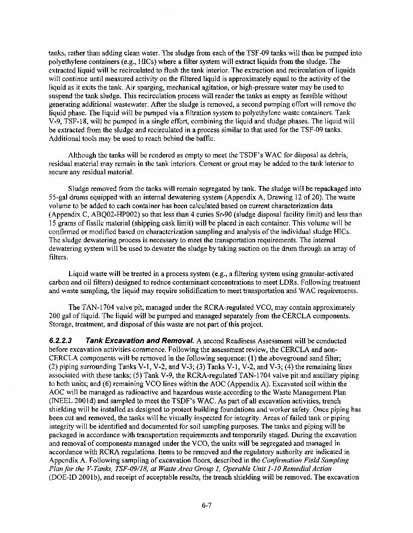
tanks, rather than adding clean water. The sludge from each of the TSF-09 tanks will then be pumped into polyethylene containers (e.g., HICs) where a filter system will extract liquids from the sludge. The extracted liquid will be recirculated to flush the tank interior. The extraction and recirculation of liquids will continue until measured activity on the filtered liquid is approximately equal to the activity of the liquid as it exits the tank. Air sparging, mechanical agitation, or high-pressure water may be used to suspend the tank sludge. This recirculation process will render the tanks as empty as feasible without generating additional wastewater. After the sludge is removed, a second pumping effort will remove the liquid phase. The liquid will be pumped via a filtration system to polyethylene waste containers. Tank V-9, TSF-18, will be pumped in a single effort, combining the liquid and sludge phases. The liquid will be extracted from the sludge and recirculated in a process similar to that used for the TSF-09 tanks. Additional tools may be used to reach behind the baffle.
Although the tanks will be rendered as empty to meet the TSDF’s WAC for disposal as debris, residual material may remain in the tank interiors. Cement or grout may be added to the tank interior to secure any residual material.
Sludge removed from the tanks will remain segregated by tank. The sludge will be repackaged into %-gal drums equipped with an internal dewatering system (Appendix A, Drawing 12 of 20). The waste volume to be added to each container has been calculated based on current characterization data (Appendix C, ABQ02-HP002) so that less than 4 curies Sr-90 (sludge disposal facility limit) and less than 15 grams of fissile material (shipping cask limit) will be placed in each container. This volume will be confirmed or modified based on characterization sampling and analysis of the individual sludge HICs. The sludge dewatering process is necessary to meet the transportation requirements. The internal dewatering system will be used to dewater the sludge by taking suction on the drum through an array of filters.
Liquid waste will be treated in a process system (e.g., a filtering system using granular-activated carbon and oil filters) designed to reduce contaminant concentrations to meet LDRs. Following treatment and waste sampling, the liquid may require solidification to meet transportation and WAC requirements.
The TAN-l 704 valve pit, managed under the RCRA-regulated VCO, may contain approximately 200 gal of liquid. The liquid will be pumped and managed separately from the CERCLA components. Storage, treatment, and disposal of this waste are not part of this project.
6.2.2.3 Tank EXCWNOII and Removal. A second Readiness Assessment will be conducted before excavation activities commence. Following the assessment review, the CERCLA and non- CERCLA components will be removed in the following sequence: (1) the aboveground sand filter; (2) piping surrounding Tanks V-l, V-2, and V-3; (3) Tanks V-l, V-2, and V-3; (4) the remaining lines associated with these tanks; (5) Tank V-9, the RCRA-regulated TAN-1704 valve pit and ancillary piping to both units; and (6) remaining VCO lines within the AOC (Appendix A). Excavated soil within the AOC will be managed as radioactive and hazardous waste according to the Waste Management Plan (INEEL 2001d) and sampled to meet the TSDF’s WAC. As part of all excavation activities, trench shielding will be installed as designed to protect building foundations and worker safety. Once piping has been cut and removed, the tanks will be visually inspected for integrity. Areas of failed tank or piping integrity will be identified and documented for soil sampling purposes. The tanks and piping will be packaged in accordance with transportation requirements and temporarily staged. During the excavation and removal of components managed under the VCO, the units will be segregated and managed in accordance with RCRA regulations. Items to be removed and the regulatory authority are indicated in Appendix A. Following sampling of excavation floors, described in the ConJirmation Field Sampling Plan for the V-Tanks, TSF-09/18, at Waste Area Group I, Operable Unit l-10 Remedial Action (DOE-ID 200 1 b), and receipt of acceptable results, the trench shielding will be removed. The excavation
6-7
will be backfilled with clean soil. The placement of a geotextile membrane between contaminated soil and clean soil will serve as a delineation marker that will allow future remedial action to determine the limits of contamination.
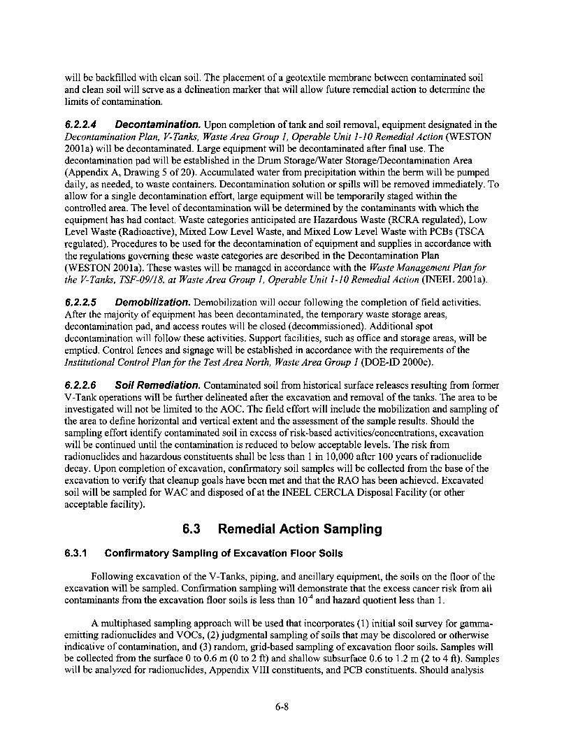
6.2.2.4 Decontamination. Upon completion of tank and soil removal, equipment designated in the Decontamination Plan, V-Tanlis, Waste Area Group I, Operable Unit I-IO Remedial Action (WESTON 200 1 a) will be decontaminated. Large equipment will be decontaminated after final use. The decontamination pad will be established in the Drum Storage/Water Storage/Decontamination Area (Appendix A, Drawing 5 of 20). Accumulated water from precipitation within the berm will be pumped daily, as needed, to waste containers. Decontamination solution or spills will be removed immediately. To allow for a single decontamination effort, large equipment will be temporarily staged within the controlled area. The level of decontamination will be determined by the contaminants with which the equipment has had contact. Waste categories anticipated are Hazardous Waste (RCRA regulated), Low Level Waste (Radioactive), Mixed Low Level Waste, and Mixed Low Level Waste with PCBs (TSCA regulated). Procedures to be used for the decontamination of equipment and supplies in accordance with the regulations governing these waste categories are described in the Decontamination Plan (WESTON 2001a). These wastes will be managed in accordance with the Waste Management Plan for the V-Tanks, TSF-09118, at Waste Area Group 1, Operable Unit I-10 Remedial Action (INEEL 2001a).
6.2.2.5 Demobilization. Demobilization will occur following the completion of field activities. After the majority of equipment has been decontaminated, the temporary waste storage areas, decontamination pad, and access routes will be closed (decommissioned). Additional spot decontamination will follow these activities. Support facilities, such as office and storage areas, will be emptied. Control fences and signage will be established in accordance with the requirements of the Institutional Control Plan for the Test Area North, Waste Area Group 1 (DOE-ID 2000e).
6.2.2.6 Soil Remediafion. Contaminated soil from historical surface releases resulting from former V-Tank operations will be further delineated after the excavation and removal of the tanks. The area to be investigated will not be limited to the AOC. The field effort will include the mobilization and sampling of the area to define horizontal and vertical extent and the assessment of the sample results. Should the sampling effort identify contaminated soil in excess of risk-based activities/concentrations, excavation will be continued until the contamination is reduced to below acceptable levels. The risk from radionuclides and hazardous constituents shall be less than 1 in 10,000 after 100 years of radionuclide decay. Upon completion of excavation, confirmatory soil samples will be collected from the base of the excavation to verify that cleanup goals have been met and that the RAO has been achieved. Excavated soil will be sampled for WAC and disposed of at the INEEL CERCLA Disposal Facility (or other acceptable facility).
6.3 Remedial Action Sampling
6.3.1 Confirmatory Sampling of Excavation Floor Soils
Following excavation of the V-Tanks, piping, and ancillary equipment, the soils on the floor of the excavation will be sampled. Confirmation sampling will demonstrate that the excess cancer risk from all contaminants from the excavation floor soils is less than lo* and hazard quotient less than 1.
A multiphased sampling approach will be used that incorporates (1) initial soil survey for gamma- emitting radionuclides and VOCs, (2) judgmental sampling of soils that may be discolored or otherwise indicative of contamination, and (3) random, grid-based sampling of excavation floor soils. Samples will be collected from the surface 0 to 0.6 m (0 to 2 ft) and shallow subsurface 0.6 to 1.2 m (2 to 4 ft). Samples will be analyzed for radionuclides, Appendix VIII constituents, and PCB constituents. Should analysis
6-8

reveal contaminants greater than the FRG, additional soil will be excavated to comply with remedial action performance objectives. Additional excavation below the safe limit of shoring installed for the tank removal will not be conducted until precautionary measures are in place and proper approval obtained. Soil sampling guidance is provided in the Confirmation Field Sampling Plan for the V-Tanks, TSF-09/l& at Waste Area Group I, Operable Unit l-10 Remedial Action (DOE-ID 2001b). Verification sampling will be conducted following additional soil excavation (if required).
6.3.2 Waste Characterization
Sludge from each V-Tank will be pumped from the tank into a polyethylene container where liquid within the sludge will be extracted and removed. Sludge from each tank will not be mixed. The sludge will then be sampled in accordance with the Field Sampling Plan for the V-Tanks (DOE-ID 2000~) for the TSDF’ s WAC. The sludge will then be repackaged into 55-gal drums and further dewatered, if required, in a manner that ensures compliance with the TSDF’s WAC. Specifically, each sludge waste container will contain less than 4 Ci Sr-90 (sludge disposal facility limit) and less than 15 grams total fissile material (shipping cask limit). The sludge will be managed in accordance with the Waste Management Plan for the V-Tanks, TSF-09/18, at Waste Area Group 1, Operable Unit l-10 Remedial Action (INEEL 2001d). The liquid from each tank will be treated using a series of filters and pumped into waste containers. As the liquid will be treated to meet LDR standards, the liquid will not necessarily be segregated according to the tank of origin. Following treatment, the liquid will be sampled for the TSDF’s WAC and LDR. If required, the liquid will be solidified to meet transportation and disposal requirements. Water analysis will ensure compliance with the TSDF’s WAC. The RCRA-regulated valve pit contents will be pumped and managed separately from the CERCLA waste based upon existing sampling data. These liquids will be managed in accordance with the Waste Management Plan (INEEL 200 1 d).
Excavated soil will be sampled for the TSDF’s WAC. The soil will be packaged in 7.3-m3 (250-ft3) polyester bags or rolloffs following sampling. The sand filter contents will be packaged separately from ’ the excavated soil and will be placed in a 55-gal drum.
Tanks, ancillary piping, equipment, and personal protective equipment (PPE) will be not be directly sampled. The excavated tanks and piping will be characterized based on their respective V-Tank sludge sampling results. The TAN- 1704 valve pit piping and concrete box will be segregated from the CERCLA components. Hazardous waste determination for PPE worn within the controlled area will be based on contact with hazardous wastes and will be managed in accordance with the Waste Management Plan (INEEL 200 1 d).
Decontamination water and stormwater will be collected and segregated, as appropriate, based on origin into water storage containers/tanks located in the drum storage/water storage/decontamination area, and characterized. Stormwater will be placed in a lO,OOO-gal tank and decontamination water will be placed in a l,OOO-gal container. The waste will be managed in accordance with the characterization. If characterization determines that the collected water exceeds the TSDF’s WAC or LDRs, the water will be treated with the backup water treatment process until disposal standards are achieved and then solidified and prepared for shipping, as required. If characterization determines that no hazardous constituents are present and no treatment is required, the collected water will be disposed of at an onsite facility such as the TAN percolation pond via a tanker truck.
6.3.3 Further Characterization of Contaminated Soil
Surface soils within and beyond the AOC boundary will be sampled to further characterize and define the nature and extent of potential contaminants that are present in the soil. This sampling will be conducted following tank removal. Should the sample results and analyses indicate contaminated soil in
6-9

excess of risk-based cleanup goals, additional soil will be excavated. To ensure that the contaminated soil has been removed, confirmatory soil sampling will be conducted at the base of the excavations. The details of this sampling will be presented in a future revision of the Confirmation Field Sampling Plan for the V-Tanks, TSF-009/18, at Waste Area Group I, Operable Unit l-10 Remedial Action (DOE-ID 200 1).
6.4 Waste Management and Transportation
The remedial actions planned at TAN under the OU l-10 ROD and this Group 2 RD/RA WP for the V-Tanks will require disposition of various waste streams, which are identified in the Waste Management Plan (INEEL 2001d) prepared as a supporting document to this Group 2 RD/RA WP. These waste streams will be managed and stored in a designated CERCLA or RCRA waste storage area until ultimate disposition in accordance with the Waste Management Plan. Under this plan, waste will be treated, if necessary, and disposed at an acceptable facility. Acceptability of the treatment and/or disposal facility is dependent upon the characterization and classification of waste in the Waste Management Plan and compliance with a treatment or disposal facility’s WAC. Facilities must be either (1) a permitted treatment or disposal facility with CERCLA offsite authority, (2) an INEEL disposal facility expressly designated to accept CERCLA waste (e.g., the INEEL CERCLA Disposal Facility), (3) a site with disposal authorization from DOE Headquarters (e.g., the Radioactive Waste Management Complex), or (4) an onsite industrial landfill (e.g., Central Facilities Area landfill).
The CERCLA site for waste management purposes, as defined in the Federal Facility Agreement and Consent Order, is the entire INEEL site area. The CERCLA site includes waste management and disposal areas such as the INEEL CERCLA Disposal Facility Complex, the Central Facilities Area Industrial Landfill, the Radioactive Waste Management Area, Argonne National Laboratory-West, and interim storage at Test Area North. Waste generated during remediation activities and stored in a temporary accumulation area within the AOC will be moved to one or more of the waste management areas within the INEEL site or sent offsite for storage, treatment, or disposal. Hazardous waste generated during remediation activities that leaves the AOC will be required to meet LDR standards prior to disposal either onsite or offsite.
Table 6-2 provides a summary of the handling and packaging requirements for each of the anticipated waste streams. Included in the table are estimated volumes, waste classifications for near surface disposal, Department of Transportation (DOT) waste-shipping classifications and packaging requirements, and planned disposal facilities. The information in the table is based on currently available sampling data and will be validated using the results of sampling.
6-10

Table 6-2. Proposed waste handling and packaging for remediation waste.
Anticipated Waste Streams
Minimum Estimated Waste Class DOT Transport Planned
Waste (10 CFR DOT Package Planned DOT Cask/Exclusive Disposal Volume 61.55) Classification Type Package Use’ Facilitg References
Piping V-Tank3 388 linear ft or 52 fi3
Other4 200 linear fi or 27 ft3
VCO Valve Pit
8 linear ft or 1 ft3
Underground Storage Tanks
Tank V- 1
Tank V-2
Tank V-3
Tank V-9
1,570 fi3
1,570 fi3
1,570 fi3
50 i-l3
Sludge Tank V- 1
Tank V-2
520 gal
520 gal
Tank V-3 652 gal
Tank V-9 250 gal
Class A- Debris
Class A- Debris
Class A- Debris
Class A- Debris
Class A- Debris
Class A- Debris
Class A- Debris
Class B- Dewatered Sludge
Class B- Dewatered Sludge
Class B- Dewatered Sludge
Class B- Dewatered
LSA II
LSA II
LSA II
LSA II
LSA II
LSA II
LSA II
Type B
Type B
Type B
Type B
Strong Tight
Strong Tight
Strong Tight
Strong Tight
Strong Tight
Strong Tight
Strong Tight
Type B
Type B
Type B
Type B
Lift-LinerTM System (88 in.) Bags/Waste Boxes (IP2)
Lift-LinerTM System (88 in.) Bags/Waste Boxes (IP2)
Lift-LinerTM System (88 in.) Bags/Waste Boxes (IP2)
Shrink wrap/ Bags12
Shrink wrap/ BagsI
Shrink wrap/ Bags”
Shrink wrap/ Bags12
55-gal drums inside Type B cask6
55-gal drums inside Type B cask6
55-gal drums inside Type B cask6
5 5-gal drums inside Type B
Exclusive Use
Exclusive Use
Exclusive Use
Exclusive Use
Exclusive Use
Exclusive Use
Exclusive Use
Duratek CNS-8- 120B
Duratek CNS-8- 120B
Duratek CNS-8- 120B
Duratek CNS-8- 120B
Envirocare
Envirocare
TBD’
Envirocare
Envirocare
Envirocare
Envirocare
ATG
ATG
ATG
ATG
Appendix C Calculation ABQ 13
None
None
Appendix C Calculation ABQ13
Appendix C Calculation ABQ 13
Appendix C Calculation ABQ 13
Appendix C Calculation ABQ 13
Appendix C Calculation ABQ02-002
Appendix C Calculation ABQ02
Appendix C Calculation ABQ02
Appendix C Calculation ABQO2
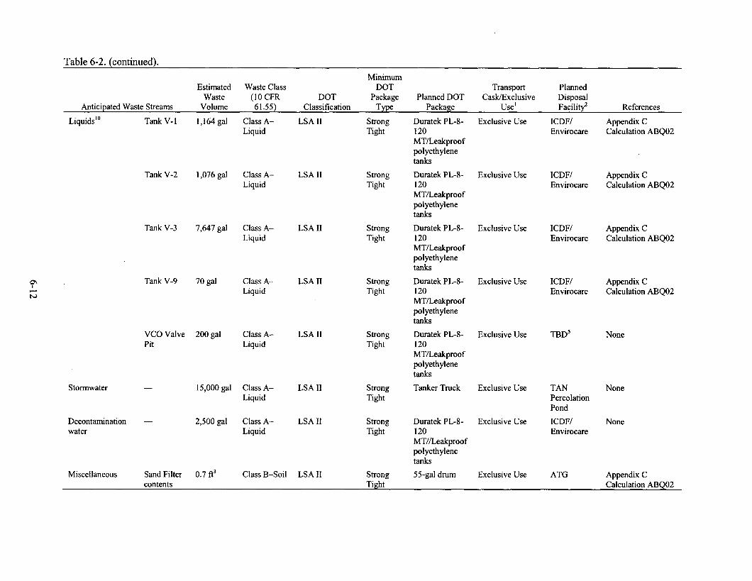
Table 6-2. (continued).
Anticipated Waste Streams
Minimum Estimated Waste Class DOT Transport Planned
Waste (10 CFR DOT Package Planned DOT Cask/Exclusive Disposal Volume 61.55) Classification Type Package Use’ Facilitg References
Tank V-2 1,076 gal Class A- Liquid
LSA II
Tank V-3 7,647 gal Class A- Liquid
LSA II
Tank V-9 70 gal Class A- Liquid
LSA II
Liquids” Tank V- 1 1,164 gal Class A- LSA II Strong Liquid Tight
Strong Tight
Strong Tight
Strong Tight
VCO Valve 200 gal Class A- LSA II Strong Pit Liquid Tight
Stormwater -
Decontamination - water
15,000 gal Class A- LSA II Strong Liquid Tight
2,500 gal Class A- LSA II Strong Liquid Tight
Miscellaneous Sand Filter 0.7 ft3 Class B-Soil LSA II Strong contents Tight
Duratek PL-8- 120 MT/Leakproof polyethylene tanks
Exclusive Use
Duratek PL-8- 120 MT/Leakproof polyethylene tanks
Exclusive Use
Duratek PL-8- 120 MT/Leakproof polyethylene tanks
Exclusive Use
Duratek PL-8- 120 MT/Leakproof polyethylene tanks
Exclusive Use
Duratek PL-8- 120 MT/Leakproof polyethylene tanks
Exclusive Use
Tanker Truck Exclusive Use
Duratek PL-8- 120 MT//Leakproof polyethylene tanks
55-gal drum
Exclusive Use
Exclusive Use
ICDF/ Envirocare
ICDF/ Envirocare
ICDF/ Envirocare
ICDF/ Envirocare
TBD5
TAN Percolation Pond
ICDF/ Envirocare
ATG
Appendix C Calculation ABQ02
Appendix C Calculation ABQ02
Appendix C Calculation ABQ02
Appendix C Calculation ABQ02
None
None
None
Appendix C Calculation ABQ02

Table 6-2. (continued).
Anticipated Waste Streams
Minimum Estimated Waste Class DOT Transport Planned
Waste (10 CFR DOT Package Planned DOT Cask/Exclusive Disposal Volume 61.55) Classification Type Package Use’ Facilie References
Soil
PPE
Concrete
Culverts
Solid Waste
1 O,OOO-gal tank
Sludge HICs
Pumps/Hoses/ Valves
Water Treatment Media and Filters
Sand Bags
Sampling Equipment, Tents, Glove Bags, Misc. Tools, Tarps, and Rags
Around V-Tanks/ Pipes
Additional Excavated Soil* -
922 yd3
2,200 yd3
350 fi3
VCO Valve Pit
88 ft3
Sand filter 22 ft3
- 36 linear fi
Trash 50 yd3
-
-
-
-
-
-
-
20 yd3
20 yd3
660 gal
10 yd3
20 yd3
Class A-Soil
Class A-Soil
Class A-
Debris
Class A- Debris
Class A- Soils
Class A- Debris
Survey Clean
Survey Clean
Class A
Class A- Debris
Class A or B9
Clean
Class A- Debris
LSA II
LSA II
LSA II
LSA II
LSA II
LSA II
Radiologically Clean
Radiologically Clean
LSA II
LSA II
LSA II
-
LSA II
Strong Tight
Strong Tight
Strong Tight
Strong Tight
Strong Tight
Strong Tight
N/A
N/A
Strong Tight
Strong Tight
Strong Tight -
Strong Tight
Lift-LinerTM System (88 in.) Bags/Rolloffs
Lift-LinerTM System (88 in.) Bags/Rolloffs
55-gal drums
Lil%LinerTM System (88 in.) Bags
Lift-LinerTM System (88 in.) Bags Lift-LinerTM System (88 in.) Bags
Dumpster
N/A
Shrink Wrap/ Bag B25
55-gal drums
-
B25s/Lift Liner Bags
Exclusive Use
Exclusive Use
Exclusive Use
Exclusive Use
Exclusive Use
Exclusive Use
N/A
N/A
Exclusive Use
Exclusive Use
Exclusive Use
-
Exclusive Use
ICDF
ICDF
ICDF/ Envirocare
TBD’
ICDF/ Envirocare
Envirocare
INEEL Industrial Landfill
KNEEL for Future Use
Envirocare
Envirocare
Envirocare/ ATG
INEEL Landfill
ICDF/Enviro care
None
None
None
None
None
None
None
None
None
None
None
None
None

Table 6-2. (continued).
Anticipated Waste Streams
Gravel for onsite - roads
Spill Platforms/ - Plastic Liners
Minimum Estimated Waste Class DOT Transport Planned
Waste (10 CFR DOT Package Planned DOT Cask/Exclusive Disposal Volume 61.55) Classification Type Package Use’ Facilitg References
475 yd3 Class A LSA II Strong Lift Liner Exclusive Use ICDF/Enviro None Tight care
50 yd3 Class A- LSA II Strong Lift Liner Exclusive Use ICDF/Enviro None Debris Tight care
Concrete Shielding - 50 yd3 Survey - Clean
- - - INEEL for Future Use
None
Shoring/Trench - Shielding
300 linear Survey - - - - Return to None f-i Clean owner-
rented
Uncontaminated - Materials (Misc.)”
PCB - Decontamination Materials (Wipes, Rags, Kerosene, etc.)
35 yd3
loft3
Survey - Clean
TSCA LSA II Waste or MLLW Class A
-
Strong Tight
- - INEEL - Landfill
55-gal drum Exclusive Use Envirocare -
N/A = Not Applicable TBD = To be determined
ICDF = INEEL CERCLA Disposal Facility
1. Exclusive Use is defined by 49 CFR 173.403.
LSA = Low Specific Activity
ATG = Allied Technology Group
2. The planned disposal facility may be another disposal facility based on Waste Acceptance Criteria as documented in the Waste Management Plan (INEEL 2001a).
3. V-Tank piping refers to those pipes that carried V-Tank contents.
4. Other piping refers to those pipes that carried material other than V-Tank contents,
5. The planned disposal facility is to be determined by the VCO Program.
6. Shipment will occur in Transport Cask to meet DOT requirements.
7. Selected disposal facility will be based on hazardous waste determination at the time of generation.
8. The volume of additional excavated soil is based on the following assumptions. In the area of excavation (1,248 f?), soil will be excavated to 2 fi below the tank bottoms; in the AOC (4,000 ti), the soil will be excavated to 2 ft; and in the remainder of the fenced area (53,000 ft?, see Appendix A drawings), the soil will be excavated to 1 ft.
9. The classification of the water treatment media will require sampling to determine the disposal option.
10. Liquids must be solidified prior to land disposal.
11. Air ducts, concrete, electrical lines, air lines, control equipment, etc.
12. Specially fabricated lift liner bag to meet DOT packaging criteria.

6.5 Inspections
6.51 Prefinal Inspection
The Agencies, or their designees, will conduct prefinal inspections at three remedial action milestones. The initial inspection will be conducted prior to tank contents removal after the Readiness Assessment has been completed. A second inspection will occur following tank removal and backfill of the excavations. The third prefinal inspection, which may be the final inspection for the V-Tanks sites (TSF-09 and TSF-18), will be conducted once all contaminated soil is excavated and removed from the site. The three prefinal inspections will provide assessments during the remedial action. The DOE-ID will notify the Agencies approximately two weeks prior to the prefinal inspection dates. The inspections will determine the status of remediation activities, including outstanding requirements and actions necessary to resolve any identified issues. All outstanding requirements, along with the actions required to resolve them, will be identified and approved by the Agencies during the prefinal inspections. At the Agencies’ discretion, the prefinal inspections may take place without a site visit.
A checklist used to document the prefinal inspections will be developed and implemented upon approval by the Agencies. Action for resolution and the anticipated schedule of completion will be noted next to the outstanding items and documented on the prefinal inspection checklist.
The prefinal inspections will be documented in prefinal inspection reports, which will contain the following elements:
0 Names of the inspection participants
0 Inspection checklist(s) containing specific project systems, components, startup procedures, or other areas to be inspected to constitute acceptance of remediation activities
0 Discussion of all documented inspection findings
0 Corrective actions to be taken to correct the deficiencies identified in the inspections, including the required corrective action, acceptance criteria or standards, and planned dates for completion of the actions
0 Date for the final inspection.
The prefinal inspection reports will be issued to indicate that the objectives of the ROD (DOE-ID 1999) are being met. The prefinal inspection reports may not be revised or finalized. The inspection will be finalized in the remedial action report documenting the prefinal inspection process. The completed prefinal inspection checklist may be included as an appendix to the remedial action report in accordance with Section 8.4 of the FFAKO (DOE-ID 199 1).
points In addi tion . to the prefinal during the project. These
6.52 Final Inspection
inspections, site visits may be conducted site visits wi 11 not use prefinal inspection
by the Agencies at various document requirements.
The final inspection will be scheduled and conducted at completion of the V-Tanks remedial action. The Agency project managers, based on the results of the prefinal inspections, will determine the need for a final inspection. The final inspection, as conducted by the Agencies’ project managers or their designees, will confirm resolution of all outstanding items identified in the prefinal inspection and verify
6-15

that the OU l-1 0 remedial action has been completed in accordance with the requirements of the ROD (DOE-ID 1999).
The final inspection will be completed following demobilization, after all excess materials and nonessential construction equipment have been removed from the sites, and the sites are considered functional and operational. Some equipment may remain onsite to repair items identified during the final inspection. Waste will be located in interim storage areas or transported to the approved TSDF.
A final inspection report will be prepared and submitted to the Agencies for review as a secondary document. The fmal inspection report will include:
Identification of the work defined in this Group 2 RD/RA WP and certification that the work was performed and final remediation goals have been met.
Explanation of any modifications to the Group 2 RD/RA WP.
Any modifications made to the remedial design during the V-Tanks remedial action phase, including the purpose of the performed modifications and results of the modifications.
Problems encountered during the V-Tanks remedial action and resolutions to these problems.
Any outstanding items from the prefinal inspection checklist that were identified and described; in responding to comments received, the prefinal inspection checklist will not be revised, but rather will be finalized in the context of the final report.
An Operations and Maintenance (O&M) Plan update, if necessary.
As-built drawings showing final contours and piping (as applicable).
The V-Tanks final inspection report, finalized through formal Agency review and comment resolution, will be incorporated into the OU l-10 remedial action report, a primary document that will be submitted after completion of the OU l-10 Group 3 remedial action and inspection. The draft OU l-10 remedial action report will be submitted within 60 days after the final inspection for OU l-10 Group 3 sites. Requirements for the OU 1 - 10 remedial action report will be addressed in the OU 1 - 10 Group 3 RDIRA WP.
6.6 Supporting Documents
The following sections provide a brief description of the documents that are associated with the V-Tanks remedial action activities, which are addressed in this RD/RA WP.
6.6.1 Remedial Action Confirmation Field Sampling Plan
The remedial action confirmation field sampling plan (FSP) (DOE-ID 2001b) specifies data needs, sampling objectives, sampling locations and frequencies, procedures, and the controls necessary to characterize the soils on the floor of the excavation following tank, pipe, and ancillary equipment removal (Section 6.2.1). The FSP is developed using the established EPA Data Quality Objectives process.
The FSP also addresses sampling requirements for secondary waste generated throughout the tank remediation. Although the intent is to use process and historical data to characterize secondary waste for disposal, there may be instances when field surveys and/or physical sampling and analysis will be
6-16

required. Additional waste characterization sampling will be performed for the V-Tank contents. This sampling will be performed in accordance with the existing Field Sampling Plan for the V-Tanks, TSF-09/18, at Waste Area Group I, Operable Unit I-IO Remedial Action (DOE-ID 2000~).
Revisions to the FSP will also address sampling to satisfy data needs for further soil characterization to determine the nature and extent of contamination at the V-Tank sites.
6.6.2 Health and Safety Plan
A site-specific HASP (INEEL 2001~) will be prepared by the INEEL to provide safety guidance applicable to INEEL staff providing oversight and construction management support for this remediation project. It is a working document that is reviewed and modified accordingly as the project planning documents are developed and finalized, and it covers the following items:
0 Task-site responsibility
0
0
Personnel training
Occupational medical program and medical surveillance
0 Safe work practices
0 Site control and security
0
0
0
Hazard evaluation
Personal protective equipment
Personnel decontamination and radiation control
0 Emergency response for the project sites.
In addition, the subcontractor will develop a project HASP (WESTON 2OOlb) that incorporates hazard analyses for each task associated with the V-Tank remediation. It aligns closely with the INEEL HASP and provides safety guidance for the subcontractor to follow as they perform the remediation activities.
Safe work documents, such as radiation work permits and job safety analyses, will be developed in accordance with existing INEEL procedures and systems to implement the HASP requirements. They will be modified, supplemented, or generated (as necessary) during the work activities to address changing conditions onsite or revisions to the work methods described in the planning documents.
6.6.3 Decontamination Plan
For the purposes of this plan, the word “decontamination” is defined as those activities required to decontaminate equipment, supplies, and exteriors of waste containers. It does not include the removal of the tank sludge from the tanks, either as part of the initial pumping process or any subsequent removal of interior materials, nor any in-tank contamination fixation or grouting. Finally, the decontamination of PPE will be addressed as a safety issue in the project-specific HASP.
6-17

The majority of the field activities that will be conducted as part of the V-Tank remedial action involve the use of various types of equipment to handle radioactive, hazardous, and PCB waste materials. The equipment may be disposed of (if highly contaminated), decontaminated to allow reuse within the INEEL (if remaining contamination has fixed radioactivity), or decontaminated to free release for radiological, hazardous, and PCB constituents. The Decontamination Plan (WESTON 200 1 a) provides the procedures to be used to meet the regulatory, INEEL, and designated TSDF’s requirements that apply to the decontamination activities.
6.6.4 Waste Management Plan
A Waste Management Plan has been prepared as a supporting document to this Group 2 RD/RA WP. The Waste Management Plan describes waste management activities for the V-Tanks’ remedial action. The plan identifies waste streams that will be generated, based upon the design and planned implementation of the remedial action. The Waste Management Plan details the approach for waste management, minimization, and disposition. In addition to newly generated waste streams, the Waste Management Plan addresses existing V-Tanks’ waste streams that are currently stored at the INEEL from past V-Tanks’ activities, which include sampling equipment and PPE from routine monitoring. Ultimate disposition of the waste streams generated or existing for the V-Tanks is based upon the characterization and classification of each waste stream, as well as WAC for acceptable treatment and/or disposal facilities.
6.6.5 Operations and Maintenance Plan
The Operations and Maintenance Plan for Test Area North, Operable Unit l-l 0 (DOE-ID 2000b) covers requirements for ongoing maintenance and inspection and environmental monitoring for OU 1 - 10 sites following the completion of remedial action. The plan also references and interfaces with the activities covered in the Institutional Control Plan for the Test Area North Waste Area Group 1 (DOE-ID 2000e) and further addresses requirements for 5-year reviews. The O&M Plan may be revised, as necessary, to incorporate changes and additions identified during the implementation of the plan.
6.6.6 Institutional Control Plan
The V-Tank remedial action will implement institutional controls in accordance with the Institutional Control Plan for the Test Area North Waste Area Group 1 (DOE-ID 2000e). The plan provides institutional control requirements for all WAG 1 sites requiring controls and inspection items for the annual inspections. The Institutional Control Plan may be revised, as necessary, to incorporate changes and additions identified during the implementation and subsequent 5-year reviews.
6.6.7 Spill Prevention/Response Program
Any inadvertent spill or release of potentially hazardous materials will be subject to project-specific spill prevention controls and countermeasures plan and the substantive requirements contained in the Emergency Plan/RCXA Contingency Plan (INEEL 1998) for TAN. Materials or substances will be handled in accordance with the recommendations of the applicable material safety data sheets or waste analyses, which will be located onsite. In the event of a spill, the emergency response plan contained in the project HASP will be activated. All materials and substances on the work site will be stored in accordance with the applicable regulations and will be stored in approved containers. An appendix to the Emergency Plan/RCRA Contingency Plan (INEEL 1998) will be prepared for the Interim Storage Sludge Facility.
6-18