5-Axis Workholding4 Swift Klamp 5-axis Workholding This work-piece clamping system maximizes the...
24
Efficient workholding TM 5-Axis Workholding
Transcript of 5-Axis Workholding4 Swift Klamp 5-axis Workholding This work-piece clamping system maximizes the...
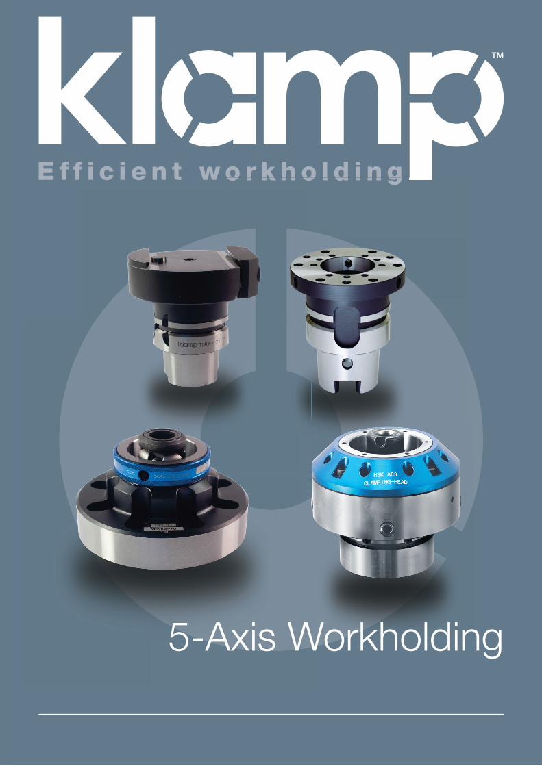
E f f i c i e n t w o r k h o l d i n g
TM
5-Axis Workholding

Notes

1www.klamp.global
Index Swift KlampIndex of Swift Klamp Products
Swift Klamp System Pages 4-7
Swift Klamp System Overview Page 4
Swift Klamp Dovetail Clamping System & HSK Interface Page 5
Swift Klamp Positioning accuracy & Work holder changing Page 6
Work-piece clamping and mounting options Page 7
Swift Klamp Manual System Pages 8-16
Manual Clamping Head (Manual Exchange) & Mounting Plates Page 8
Dovetail Clamping Systems Page 9 -10
Dovetail Preparation & Dovetail Cutter Page 11
Pre-machining Vice for Raw Billet Dovetail Preparation Page 12
Machine Ready Dovetailed blanks Page 13
Flange Clamping & Centering boss Page 14
Adaptor (Flange Clamping) Page 15
Side Clamp Workholders Page 16
Swift Klamp Automation System Pages 17-18
Overview of Automation Page 17
Hydraulic Automatic Clamping Head (Automatic Exchange) Page 17
Hydraulic Automatic Clamping Head Specifications Page 18
Swift Klamp Direct Mount Systems Page 19
Technical Data Page 20


5-Axis WorkholdingSwift Klamp Series
5-A
xis
Wo
rkh
old
ing
Sw
ift
Kla
mp
Se
rie
s
4 www.klamp.global
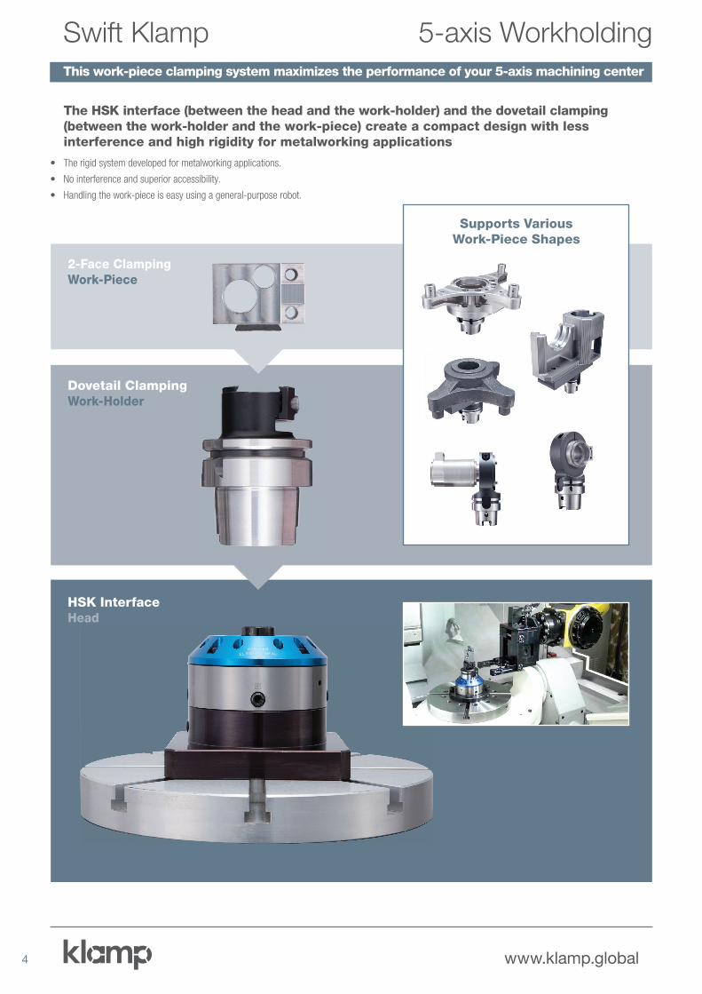
5-axis WorkholdingSwift KlampThis work-piece clamping system maximizes the performance of your 5-axis machining center
The HSK interface (between the head and the work-holder) and the dovetail clamping (between the work-holder and the work-piece) create a compact design with less interference and high rigidity for metalworking applications
• The rigid system developed for metalworking applications.
• No interference and superior accessibility.
• Handling the work-piece is easy using a general-purpose robot.
2-Face ClampingWork-Piece
Dovetail ClampingWork-Holder
HSK InterfaceHead
Supports Various Work-Piece Shapes

5www.klamp.global
Dovetail Clamping System
HSK Interface
Strong Clamping with Small Clamping Area
• By minimizing the clamping surface of the work-piece, optimum tool
holder accessibility is possible.
• It allows stable and heavy machining from various directions
without the work-piece rising.
Strong Clamping
• Uses the HSK-A type, time-proven
tool holder shank to connect the
head and the work-piece holder.
Superior Bending Rigidity
• The dovetail clamping work-holder with the
HSK head works with heavy-duty milling.
Dovetail Clamping
Conventional Clamping
Large
3mm
Clamping Area
N: 1273min-1
F: 190mm/min
HSK TypeClamping Force
kN
HSK-A40 10
HSK-A63 20
HSK-A100 30 Head
Head
HSK Two
Face Contact
Dovetail
Clamping
Ø25mm
25mm
Work-Holder
Work-Holder
300mm
Carbide Drill
6300N
S45C
er
5-axis WorkholdingSwift Klamp

6 www.klamp.global
High Positioning Accuracy
Rotating Direction
0.1~0.3mm/D
D
Concentricity
L
L = 3xD
Z Axis Direction
2μm/L
1μm/L
D
HSK-A40 40
HSK-A63 63
HSK-A100 100
Offsetting the work-piece position in the rotating direction using a touch probe
• Measuring two locations along the
work-piece side face using a touch
probe enables you to offset the
machine table angle easily.
e
X X
YY
BLUM high accuracy touch probe
Correcting angle
For Automation (Hydraulic Automatic Clamping Head)
Hydraulic Automatic
Clamping Head
The hydraulic clamping design allows
for automated work-piece changing,
and makes it possible for you to combine
your machining centers with robots to
create a fully-automated system.
Quick Work-piece Changing (Manual Clamping Head)
Off-line setup in advance allows quick work-piece changing, minimizing machine downtime.
Clamping
Unclamping
5-axis WorkholdingSwift Klamp

7www.klamp.global
Work-piece Clamping & Mounting Options
Workpiece Options Direct Clamping
Workholder Options
Head Options
Machine Table
The Swift Klamp System:
HSK-A40
HSK-A63
HSK-A100
Dovetail
(max. 200mm)Rectangular
(max.depth 30mm )
Side Clamp A
Square
(max. 40mm)
Side Clamp B
Small diameters
(max. 25mm)
Collet HolderDovetail Clamping
Page 9
Dovetail Vise
Pages 9-10
Mounting Plate
Automatic Clamping
Mounting Plate
Hydraulic Automatic Clamping Head
Pages 17-18
Manual Clamping Head
Page 8
Mounting Plate
Manual Clamping
Large Diameters
(max. 200mm)
Flange Clamping
Pages 14-15
Flange Clamping
Page 19
Dovetail Clamping
Page 19
5-axis WorkholdingSwift Klamp
Page 16
8 www.klamp.global
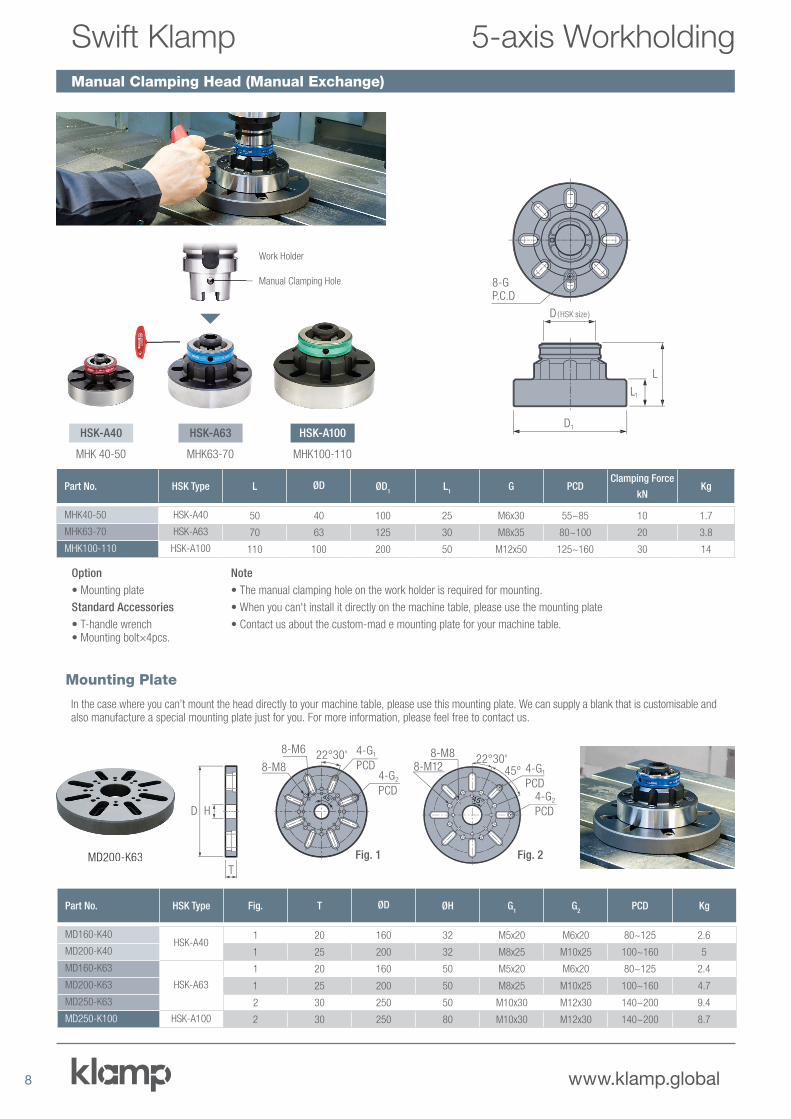
Manual Clamping Head (Manual Exchange)
MD200-K63
D
T
H
Fig. 2Fig. 1
4-G2
PCD
8-M8
8-M6 4-G1
PCD22°30'
45°
8-M8
4-G1
PCD4-G2
PCD
22°30'45°8-M12
45°4 °4444
Part No. HSK Type L ØD ØD1
L1
G PCDClamping Force
kNKg
MHK40-50 HSK-A40 50 40 100 25 M6x30 55~85 10 1.7
MHK63-70 HSK-A63 70 63 125 30 M8x35 80~100 20 3.8
MHK100-110 HSK-A100 110 100 200 50 M12x50 125~160 30 14
Part No. HSK Type Fig. T ØD ØH G1
G2
PCD Kg
MD160-K40HSK-A40
1 20 160 32 M5x20 M6x20 80~125 2.6
MD200-K40 1 25 200 32 M8x25 M10x25 100~160 5
MD160-K63
HSK-A63
1 20 160 50 M5x20 M6x20 80~125 2.4
MD200-K63 1 25 200 50 M8x25 M10x25 100~160 4.7
MD250-K63 2 30 250 50 M10x30 M12x30 140~200 9.4
MD250-K100 HSK-A100 2 30 250 80 M10x30 M12x30 140~200 8.7
HSK-A100
MHK100-110
HSK-A40
MHK 40-50
HSK-A63
MHK63-70
Work Holder
Manual Clamping Hole
D1
D ( HSK size )
L1
L
8-G P.C.D
Option
• Mounting plate
Standard Accessories
• T-handle wrench • Mounting bolt×4pcs.
Note
• The manual clamping hole on the work holder is required for mounting.
• When you can't install it directly on the machine table, please use the mounting plate
• Contact us about the custom-mad e mounting plate for your machine table.
In the case where you can’t mount the head directly to your machine table, please use this mounting plate. We can supply a blank that is customisable and also manufacture a special mounting plate just for you. For more information, please feel free to contact us.
Mounting Plate
5-axis WorkholdingSwift Klamp

9www.klamp.global
Dovetail Clamping
NoteDovetail machining of the work-piece clamping area using an angular cutter is required prior to machining.
Part No. HSK Type L L1
ØC W H 2G SW Kg
TDK40-17.5-55
HSK-A40
55 25 30 17.5 2 M5 4 0.4
TDK40-25-55 55 28 40 25 3 M6 5 0.6
TDK40-35-55 55 25 50 35 3 M6 5 0.7
TDK40-50-60 60 30 70 50 5 M8 6 1.2
TDK63-25-65
HSK-A63
65 27 40 25 3 M6 5 1.2
TDK63-35-65 65 27 50 35 3 M6 5 1.3
TDK63-50-70 70 30 70 50 5 M8 6 1.8
TDK63-70-75 75 35 100 70 3 M10 8 3
TDK100-35-70
HSK-A100
70 27 50 35.0 3 M6 5 3.3
TDK100-50-75 75 32 70 50 5 M8 6 3.8
TDK100-70-75 75 35 100 70 5 M10 8 5
TDK100-100-85 85 40 140 100 10 M12 10 7.7
TDK63-25-65
H2
L1
L
SW
W C
G
Examples of work-piece clamping
Dovetail Workholder
5-axis WorkholdingSwift Klamp
Angular Cutter
For more information, please go to page 11.
DAK63-110
L1 3
L
W
Standard Accessories• 8mm hex wrench
Note• Dovetail machining of the work-piece clamping area using an angular cutter is required prior to machining.
• Work-piece clamping jaws move individually.
• Please use screw holes on the top face as necessary.
12
42
G
15
15
S
Clamping jaw
Dovetail Vice A
Part No. HSK Type S W G (depth) L L1
Kg
DAK63-110 HSK-A63 110 36~80 24 – M8(10) 90 35 5.7
DAK100-140 HSK-A100 140 36~110 52 – M8(10) 100 35 9.9
Angular Cutter
For more information, please go to page 11.
10 www.klamp.global
Xxxxx
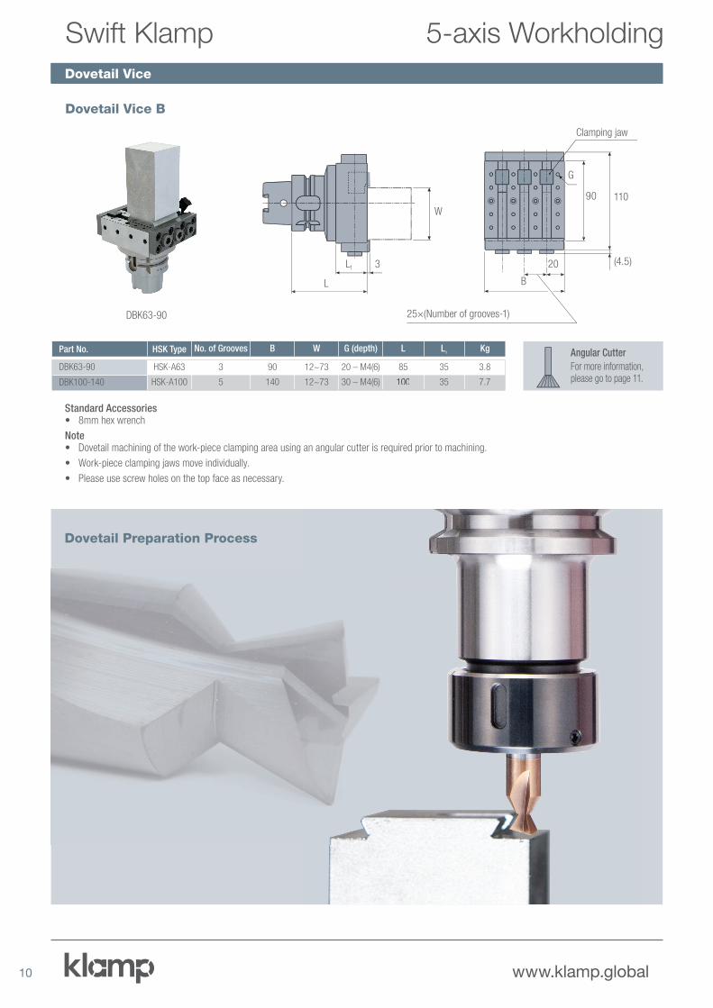
DBK63-90
L1
L
3
W
G
90
20
B
110
(4.5)
25×(Number of grooves-1)
Clamping jaw
Standard Accessories• 8mm hex wrench
Note• Dovetail machining of the work-piece clamping area using an angular cutter is required prior to machining.
• Work-piece clamping jaws move individually.
• Please use screw holes on the top face as necessary.
Dovetail Vice B
Part No. HSK Type No. of Grooves B W G (depth) L L1
Kg
DBK63-90 HSK-A63 3 90 12~73 20 – M4(6) 85 35 3.8
DBK100-140 HSK-A100 5 140 12~73 30 – M4(6) 100 35 7.7
Angular Cutter
For more information, please go to page 11.
Dovetail Vice
5-axis WorkholdingSwift Klamp
Dovetail Preparation Process

11www.klamp.global
XxxxxDovetail Preparation
Work holder Size W H P SW SD
17.5 17.5 2.5 2.5 4 2
25 25 3.5 2.5 6 2.5
35 35 3.5 5.5 8 2.5
50 50 5.5 9 10 4
70 70 5.5 18 12 4
100 100 10.5 26 15 4
Dovetail Grooving Dovetail Dimensions
SW(width)
SD(depth)
PW±0.1
H
60°
Procedures for Machining a Work-piece
Pre-machining a dovetail on the work-piece using the angular cutter.
Insert the dovetail into the dovetail groove, tighten it and you are ready to machine.
Cut off the work-piece dovetail
Swift Klamp Dovetail Cutter
Part No.Cutter Ø
D1
Shank Ø
D2
Neck Ø
D3
Cutter Length
L1
Cutting Head Depth
L2
Cutter Angle
A
Corner Radius
RNo. of Flutes
Weight
Kgs
TDC60A 20 20 8.45 90 10 60o 0.3 3 0.25
The Swift Klamp dovetail cutter can be used to prepare all workpieces for all the Swift Klamp dovetail systems. The TDC60A three flute solid carbide (micrograde) 60 degree angle dovetail cutter is intended for hard-material workpieces: steel, titanium, and others.
All Swift Klamp Dovetail work holders are attached to the workpiece using a simple dovetail. Setup is quick, easy and dovetail work holders only require the minimum of material to hold the workpiece. That means less waste, easy preparation, and no distortion to the workpiece.
• Suitable to machine Aluminium, Steel and Titanium• Solid carbide (Micrograin Grade)• Fully CNC ground• One size fits all - Swift Klamp dovetail cutter to suit all workholder sizes
5-axis WorkholdingSwift Klamp
D2 D1 A
D3
L1
L2
R

12 www.klamp.global
Pre-machining Vice for Raw Billet Dovetail Preparation
5-axis WorkholdingSwift Klamp
Part No. A B C D E F G H JMax. Clamping force
kNKg
VC103N 355.5 160 195.5 273 86 113 105 128 109 20 16
VC104N 431.5 200 231.5 349 126 149 181 204 112 20 19
* Zero range means clamp without a step-up mechanism. Clamp force shows
an allowable amount.
ModelClamping Force Range
3 2 1 0
VC103N20kN 15kN 10kN 8kN
VC104N
• High rigidity steel body
• Low height – offering a large machining area
• Aluminium jaws provided as standard allowing irregular and circular workpieces to be gripped by forming
• Large jaw opening allowing up top 204mm workpieces to be gripped.
• Stable clamping force provided by the mechanical force amplifier toggle mechanism
• Minimal jaw lift – 0.015mm or less
Aluminium Jaws Application
Standard Accessories• Clamp device assembly (clamp device, T-nut(s), bolt(s), washer(s)), handle, L-shaped hexagonal wrench, C-caps, slide cover.
Option• Parallel clamp device, stepped guide block, ratchet handle, extension bar, soft jaws (a set of moving side and fixed side jaws).• The guide block can be changed to suit the machine. In this case please contact us.
Irregular Workpiece Gripping
Other vice specifications are available. For more information, please contact us.
2x2-M8
90 G
E
D
B C
A
82.5
14.5 43 72
F
1 73 64
29 3535 3830
10
105
40
2020
12.565
5
3413
5
14
20
H max.
2x2-M8
M8
14.5 14.5
M8
φφ
φφ
φφ
φφ
100
Movable Side Fixed Side
100
16.5
16.5
10.5
20
35
35
70
11 11
1717
15 27.5 45 27.515
2010
.5
J
100
15 21
Width 35
Hex. socket head cap screw
M12x45
514
103 40
17
13www.klamp.global
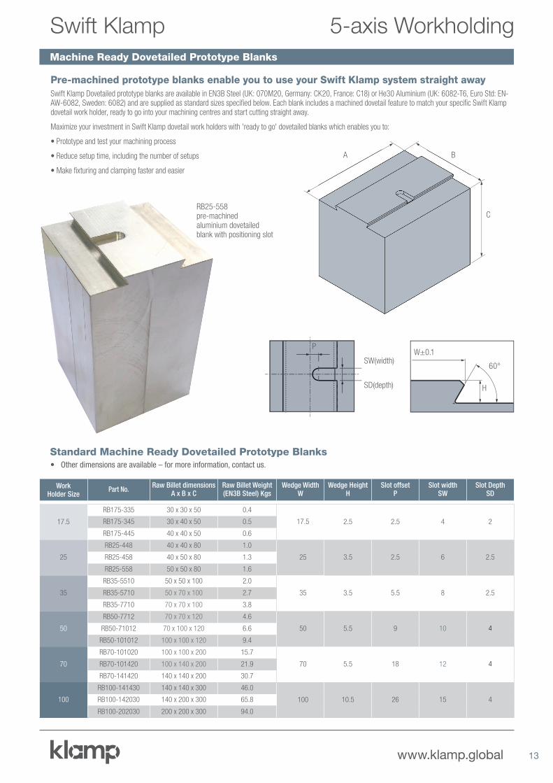
Machine Ready Dovetailed Prototype Blanks
5-axis WorkholdingSwift Klamp
Work Holder Size
Part No.Raw Billet dimensions
A x B x CRaw Billet Weight (EN3B Steel) Kgs
Wedge WidthW
Wedge HeightH
Slot offsetP
Slot widthSW
Slot DepthSD
17.5
RB175-335 30 x 30 x 50 0.4
17.5 2.5 2.5 4 2RB175-345 30 x 40 x 50 0.5
RB175-445 40 x 40 x 50 0.6
25
RB25-448 40 x 40 x 80 1.0
25 3.5 2.5 6 2.5RB25-458 40 x 50 x 80 1.3
RB25-558 50 x 50 x 80 1.6
35
RB35-5510 50 x 50 x 100 2.0
35 3.5 5.5 8 2.5RB35-5710 50 x 70 x 100 2.7
RB35-7710 70 x 70 x 100 3.8
50
RB50-7712 70 x 70 x 120 4.6
50 5.5 9 10 4RB50-71012 70 x 100 x 120 6.6
RB50-101012 100 x 100 x 120 9.4
70
RB70-101020 100 x 100 x 200 15.7
70 5.5 18 12 4RB70-101420 100 x 140 x 200 21.9
RB70-141420 140 x 140 x 200 30.7
100
RB100-141430 140 x 140 x 300 46.0
100 10.5 26 15 4RB100-142030 140 x 200 x 300 65.8
RB100-202030 200 x 200 x 300 94.0
Standard Machine Ready Dovetailed Prototype Blanks• Other dimensions are available – for more information, contact us.
RB25-558 pre-machined aluminium dovetailed blank with positioning slot
A B
C
SW(width)
SD(depth)
PW±0.1
H
60°
Pre-machined prototype blanks enable you to use your Swift Klamp system straight awaySwift Klamp Dovetailed prototype blanks are available in EN3B Steel (UK: 070M20, Germany: CK20, France: C18) or He30 Aluminium (UK: 6082-T6, Euro Std: EN-AW-6082, Sweden: 6082) and are supplied as standard sizes specified below. Each blank includes a machined dovetail feature to match your specific Swift Klamp dovetail work holder, ready to go into your machining centres and start cutting straight away.
Maximize your investment in Swift Klamp dovetail work holders with 'ready to go' dovetailed blanks which enables you to:
• Prototype and test your machining process
• Reduce setup time, including the number of setups
• Make fixturing and clamping faster and easier

14 www.klamp.global
XxxxxFlange Clamping
Part No. HSK Type Fig. L ØD ØD1
ØD2
ØD3
Ød h1
h2
T1
T2
T3
Ød2
Ød3
G1
G2
Kg
FPK40-40-35HSK-A40
3 35 40 32 - - 25 12 4 M4×6 - - - - M6×15 M4×8 0.3
FPK40-63-40 2 40 63 32 50 - 25 12 4 M4×6 M5 - 5.5 - M6×20 M4×8 0.5
FPK63-63-45
HSK-A63
3 45 63 50 - - 40 13 5 M5×8 - - - - M10×20 M6×10 0.9
FPK63-85-50 2 50 85 50 73 - 40 13 5 M5×8 M6 - 6.6 - M10×25 M6×10 1.2
FPK63-110-55 1 55 110 50 73 95 40 13 5 M5×8 M6×9 M8 6.6 9 M10×30 M6×10 1.7
FPK100-100-55
HSK-A100
3 55 100 85 - - 70 17 7 M8×12 - - - - M12×25 M8×16 3.0
FPK100-130-65 2 65 130 85 115 - 70 17 7 M8×12 M8 - 9 - M12×35 M8×16 4.2
FPK100-160-70 1 70 160 85 115 140 70 17 7 M8×12 M8×12 M10 9 11 M12×40 M8×16 5.3
3-G2
3-G23-G2
9-T1
6-d2
6-d3
3-T23-T3
D1D2
D3
FPK63-85-50
Fig. 2Fig. 1 Fig. 3L
Ddh1
h2
G1
CBK40-15
Centering Boss (Flange Clamping)
3h D5
D4
Work-piece
Set screw (G2)
Center bolt(G 1)Work Holder
CenteringBoss
Chamfering surface (B1)
Standard Accessories• Center bolt (G1) ×1pc. • Set screw (G2) ×3pcs. • M6 special small head bolt (the head diameter size is the same as the M5 bolt. ) ×3 pcs.
( A63-FP85-50 / A63-FP110-55 ) • Regular M6 cap screw doesn't fit.
Note• Centering boss • Adapter
Not Option• Use the G2 set screw when you use the center blot to clamp the work-piece. When you need whirl-stop machining of a work-piece,
make a flat surface on the work-piece and clamp it using a set screw (G2).
Note
When you do not want the work-piece to rotate, make a flat surface on the ØD (B1) of the boss, and fix it using a set screw (G2).
Part No. HSK Type ØD4 ØD5 h Kg
CBK40-15 HSK-A40150
-0.02725 15 0.05
CBK63-25 HSK-A633.50-0.033
40 16 0.1
CBK100-40 HSK-A1003.50-0.039
70 20 0.5
5-axis WorkholdingSwift Klamp
Flange Clamp Workholder
15www.klamp.global
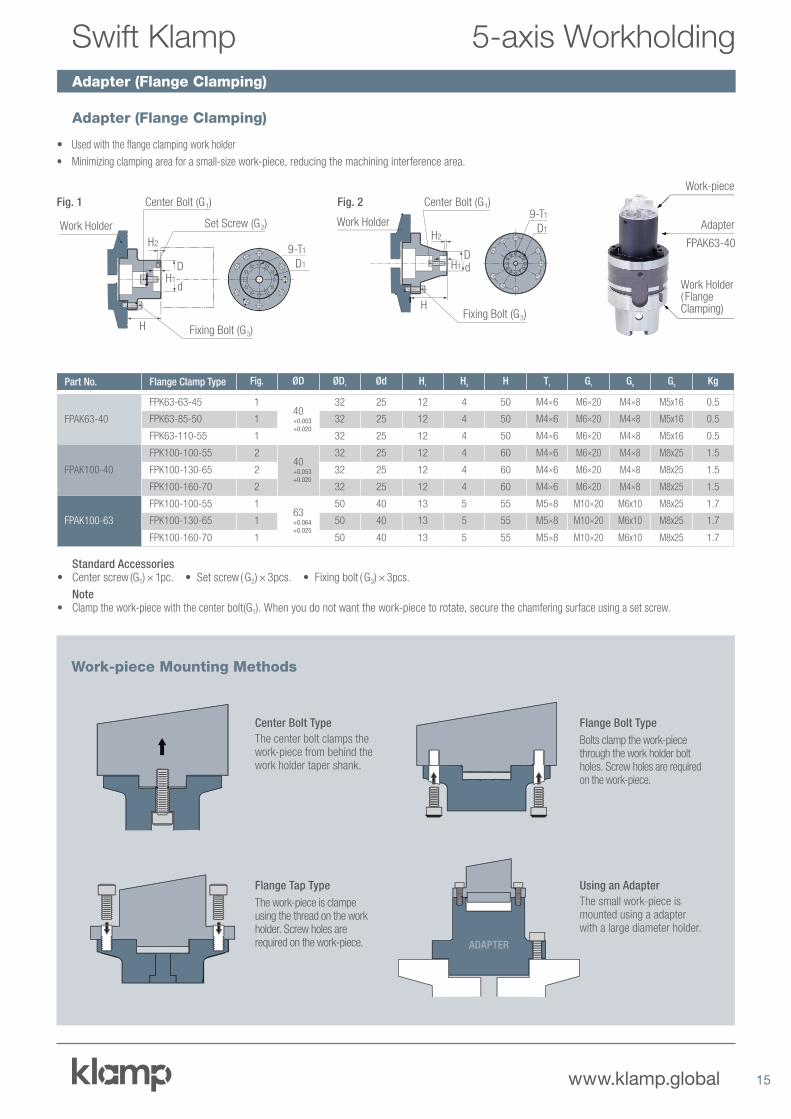
Center Bolt Type
The center bolt clamps the work-piece from behind the work holder taper shank.
Flange Bolt Type
Bolts clamp the work-piece through the work holder bolt holes. Screw holes are required on the work-piece.
Flange Tap Type
The work-piece is clampe using the thread on the work holder. Screw holes are required on the work-piece.
Using an Adapter
The small work-piece is mounted using a adapter with a large diameter holder.
ADAPTER
Adapter (Flange Clamping)
Adapter (Flange Clamping)
FPAK63-40
Adapter
Work Holder( Flange Clamping)
Work-piece
• Used with the flange clamping work holder
• Minimizing clamping area for a small-size work-piece, reducing the machining interference area.
Standard Accessories• Center screw (G1) × 1pc. • Set screw ( G2) × 3pcs. • Fixing bolt ( G3) × 3pcs.
Note• Clamp the work-piece with the center bolt(G1). When you do not want the work-piece to rotate, secure the chamfering surface using a set screw.
Fig. 1
H2
H1
H
D
d
Work Holder
9-T1
D1
Center Bolt (G 1)
Set Screw (G 2)
Fixing Bolt (G 3)
Part No. Flange Clamp Type Fig. ØD ØD1
Ød H1
H2
H T1
G1
G2
G3
Kg
FPAK63-40
FPK63-63-45 140+0.053+0.020
32 25 12 4 50 M4×6 M6×20 M4×8 M5x16 0.5
FPK63-85-50 1 32 25 12 4 50 M4×6 M6×20 M4×8 M5x16 0.5
FPK63-110-55 1 32 25 12 4 50 M4×6 M6×20 M4×8 M5x16 0.5
FPAK100-40
FPK100-100-55 240+0.053+0.020
32 25 12 4 60 M4×6 M6×20 M4×8 M8x25 1.5
FPK100-130-65 2 32 25 12 4 60 M4×6 M6×20 M4×8 M8x25 1.5
FPK100-160-70 2 32 25 12 4 60 M4×6 M6×20 M4×8 M8x25 1.5
FPAK100-63
FPK100-100-55 163+0.064+0.025
50 40 13 5 55 M5×8 M10×20 M6x10 M8x25 1.7
FPK100-130-65 1 50 40 13 5 55 M5×8 M10×20 M6x10 M8x25 1.7
FPK100-160-70 1 50 40 13 5 55 M5×8 M10×20 M6x10 M8x25 1.7
Fig. 2
H2
H1
H
Dd
Work Holder9-T1
D1
Center Bolt (G 1)
Fixing Bolt (G 3)
5-axis WorkholdingSwift Klamp
Work-piece Mounting Methods
16 www.klamp.global
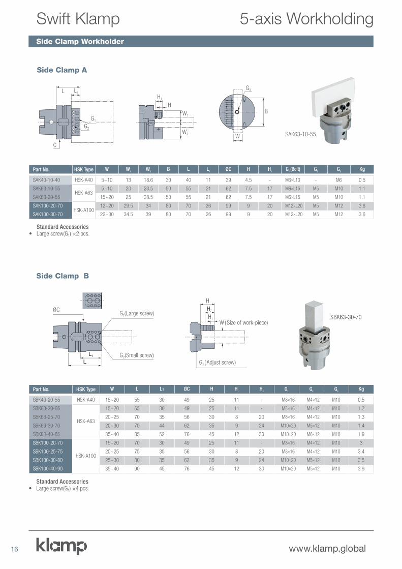
Side Clamp Workholder
SBK63-30-70H1
H2
H
G1 ( Adjust screw)
W ( Size of work-piece)
ØC
L1LL
LG2(Small screw)
G1(Large screw)
Standard Accessories• Large screw(G1) ×4 pcs.
Part No. HSK Type W L L1 ØC H H1
H2
G1 G
2G
3Kg
SBK40-20-55 HSK-A40 15~20 55 30 49 25 11 - M8×16 M4×12 M10 0.5
SBK63-20-65
HSK-A63
15~20 65 30 49 25 11 - M8×16 M4×12 M10 1.2
SBK63-25-70 20~25 70 35 56 30 8 20 M8×16 M4×12 M10 1.3
SBK63-30-70 20~30 70 44 62 35 9 24 M10×20 M5×12 M10 1.4
SBK63-40-85 35~40 85 52 76 45 12 30 M10×20 M6×12 M10 1.9
SBK100-20-70
HSK-A100
15~20 70 30 49 25 11 - M8×16 M4×12 M10 3
SBK100-25-75 20~25 75 35 56 30 8 20 M8×16 M4×12 M10 3.4
SBK100-30-80 25~30 80 35 62 35 9 24 M10×20 M5×12 M10 3.5
SBK100-40-90 35~40 90 45 76 45 12 30 M10×20 M5×12 M10 3.9
Side Clamp B
5-axis WorkholdingSwift Klamp
SAK63-10-55
C
G1
L1L
G2
H1
H
W1
W2
B
G3
W
Standard Accessories• Large screw(G1) ×2 pcs.
Part No. HSK Type W W1
W2
B L L1
ØC H H1
G1 (Bolt) G
2G
3Kg
SAK40-10-40 HSK-A40 5~10 13 18.6 30 40 11 39 4.5 - M6×L10 - M6 0.5
SAK63-10-55HSK-A63
5~10 20 23.5 50 55 21 62 7.5 17 M6×L15 M5 M10 1.1
SAK63-20-55 15~20 25 28.5 50 55 21 62 7.5 17 M6×L15 M5 M10 1.1
SAK100-20-70HSK-A100
12~20 29.5 34 80 70 26 99 9 20 M12×L20 M5 M12 3.6
SAK100-30-70 22~30 34.5 39 80 70 26 99 9 20 M12×L20 M5 M12 3.6
Side Clamp A

17www.klamp.global
Overview of Automation
5-axis WorkholdingSwift Klamp
Hydraulic Automatic Clamping Head (Automatic Exchange)
The System Development with the Systems Integrator
Work-piece Shelf Robot
Loading and unloading of the work holder
Robot Control Unit
Robot Finger
Tool Holder Control Unit
Pump
Clamping/Unclamping
Seating/Blow
Process Start/Finish
Clamping (seating confirmation)/Unclamping
Swift Klamp
5-axis Machining Center Operation Unit
Air
Hydraulic
Signal
• We can provide the Swift Klamp operation unit, pump unit, work-stocker,
robot finger and tool holder.
• Required specifications at 5-axis machining center, plumbing of 2 channels
of hydraulic and 2 channels of pneumatic are required.
• Contact us for details.
10C
S
Hydraulic un-clamping connection port
Air-sensor connection portAir purge connection port
6-air purge hole
Hydraulic clamping connection port
Air-sensor blowing hole
8-G ( Clamp bolt )
P.C.D. 2
P.C.D. 1
D1
L
L1
D ( HSK size )
S - 0.4
Note Hydraulic capacity: 3.5MPa
Part No. HSK Type L ØD ØD1
ØS(g6)
L1
G PCD1
PCD2
Clamping Force
kN
Max Loading Weight
Kg
AHK40-64 HSK-A40 64 40 70 45 35 M5x20 55 35 6 50 1.1
AHK63-89 HSK-A63 89 63 100 65 50 M6x30 80 55 24 140 3.1
AHK100-139 HSK-A100 139 100 140 100 80 M8x45 120 88 55 640 9.7
HSK-A100
AHK100-139
HSK-A40
AHK40-64
HSK-A63
AHK63-89
Work Holder
18 www.klamp.global
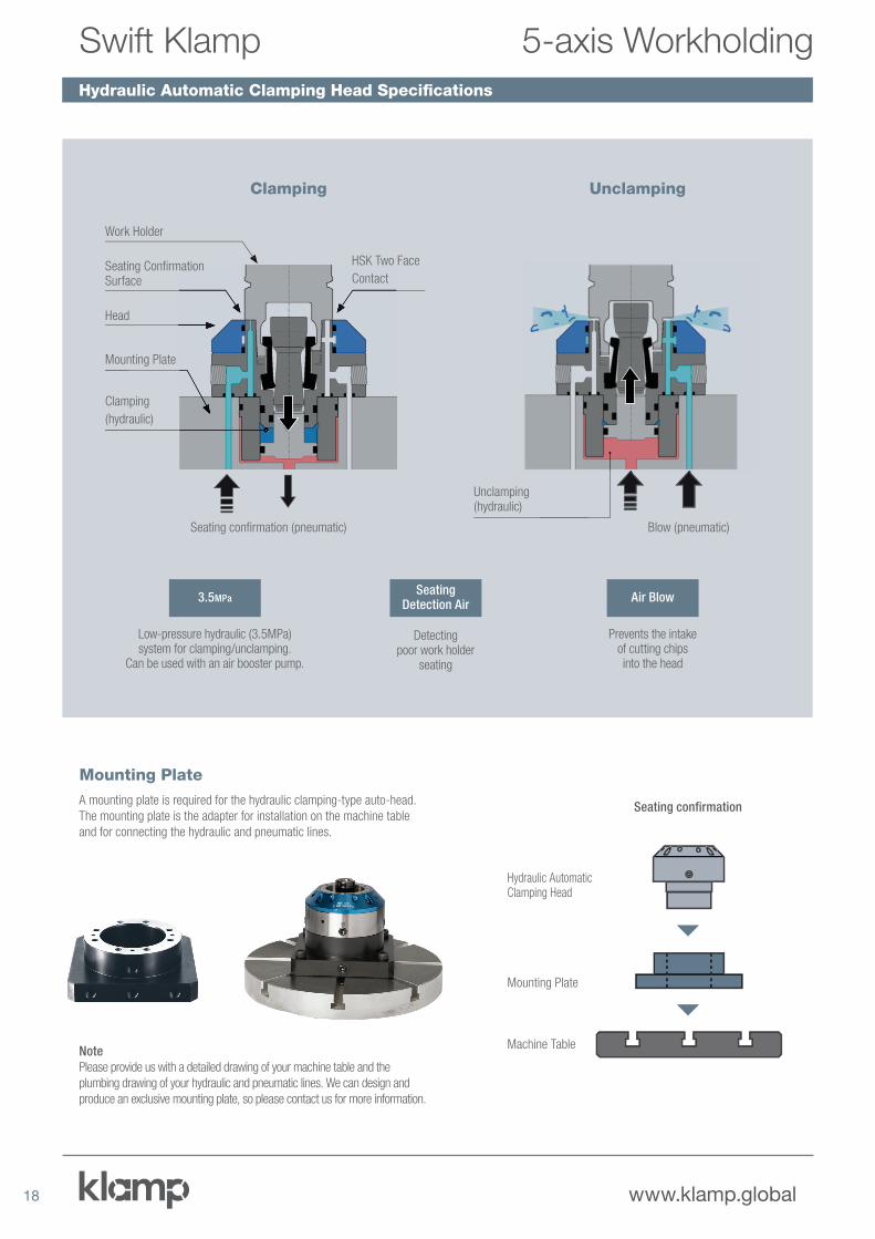
Hydraulic Automatic Clamping Head Specifications
Seating Confirmation Surface
HSK Two Face
Contact
Work Holder
Head
Mounting Plate
Clamping
(hydraulic)
Seating confirmation (pneumatic)
3.5MPa
Low-pressure hydraulic (3.5MPa) system for clamping/unclamping.
Can be used with an air booster pump.
Air Blow
Prevents the intake of cutting chips into the head
Seating Detection Air
Detecting poor work holder
seating
Clamping
Unclamping(hydraulic)
Blow (pneumatic)
Unclamping
A mounting plate is required for the hydraulic clamping-type auto-head.
The mounting plate is the adapter for installation on the machine table
and for connecting the hydraulic and pneumatic lines.
Note
Please provide us with a detailed drawing of your machine table and the
plumbing drawing of your hydraulic and pneumatic lines. We can design and
produce an exclusive mounting plate, so please contact us for more information.
Seating confirmation
Hydraulic Automatic Clamping Head
Mounting Plate
Machine Table
Mounting Plate
5-axis WorkholdingSwift Klamp
19www.klamp.global
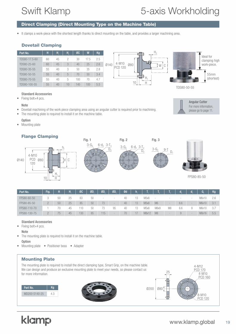
Direct Clamping (Direct Mounting Type on the Machine Table)
5-axis WorkholdingSwift Klamp
Part No. Fig. H H1
ØC ØD1
ØD2
ØD3
Ød h1
T1
T2
T3
d2
d3
G2
Kg
FPS80-60-50 3 50 25 63 50 - - 40 13 M5x8 - - - - M6x10 2.6
FPS80-85-50 2 50 25 85 50 73 - 40 13 M5x8 M6 - 6.6 - M6x10 3.1
FPS80-110-70 1 70 45 110 50 73 95 40 13 M5x8 M6x9 M8 6.6 9 M6x10 3.7
FPS80-130-75 2 75 45 130 85 115 - 70 17 M8x12 M8 - 9 - M8x16 5.5
Part No. Kg
MD200-S140-25 4.3
Flange Clamping
Mounting Plate
• It clamps a work-piece with the shortest length thanks to direct mounting on the table, and provides a larger machining area.
Part No. H H1
H2
ØC W Kg
TDS80-17.5-60 60 45 2 30 17.5 2.5
TDS80-25-60 60 45 3 40 25 2.6
TDS80-35-55 55 40 3 50 35 2.8
TDS80-50-55 55 40 5 70 50 3.4
TDS80-70-55 55 40 5 100 70 4.7
TDS80-100-55 55 40 10 140 100 5.5
Dovetail Clamping
Standard Accessories
• Fixing bolt×4 pcs.
Note
• Dovetail machining of the work piece clamping area using an angular cutter is required prior to machining.
• The mounting plate is required to install it on the machine table.
Option
• Mounting plate
55mm (shortest)
Ideal for clamping high work-piece.
TDS80-50-55
10
Ø140 Ø804-M10 PCD 120
H2
H1
H
W C
Ø200 Ø80
25
4-M12PCD 170
4-M10PCD 160
8-M10PCD 120
Standard Accessories
• Fixing bolt×4 pcs.
Note
• The mounting plate is required to install it on the machine table.
Option
• Mounting plate • Positioner boss • Adapter
The mounting plate is required to install the direct clamping type, Smart Grip, on the machine table.
We can design and produce an exclusive mounting plate to meet your needs, so please contact us
for more information.
FPS80-85-50
Ø140
10
Ø80
4-M10 PCD120
h1
H1
H
d C
Fig. 2
3-G2 6-d2 3-T2
D2
Fig. 3
3-G2 9-TD1
Fig. 1
3-G2 6-d3 3-T3
D3
Angular Cutter
For more information, please go to page 11.
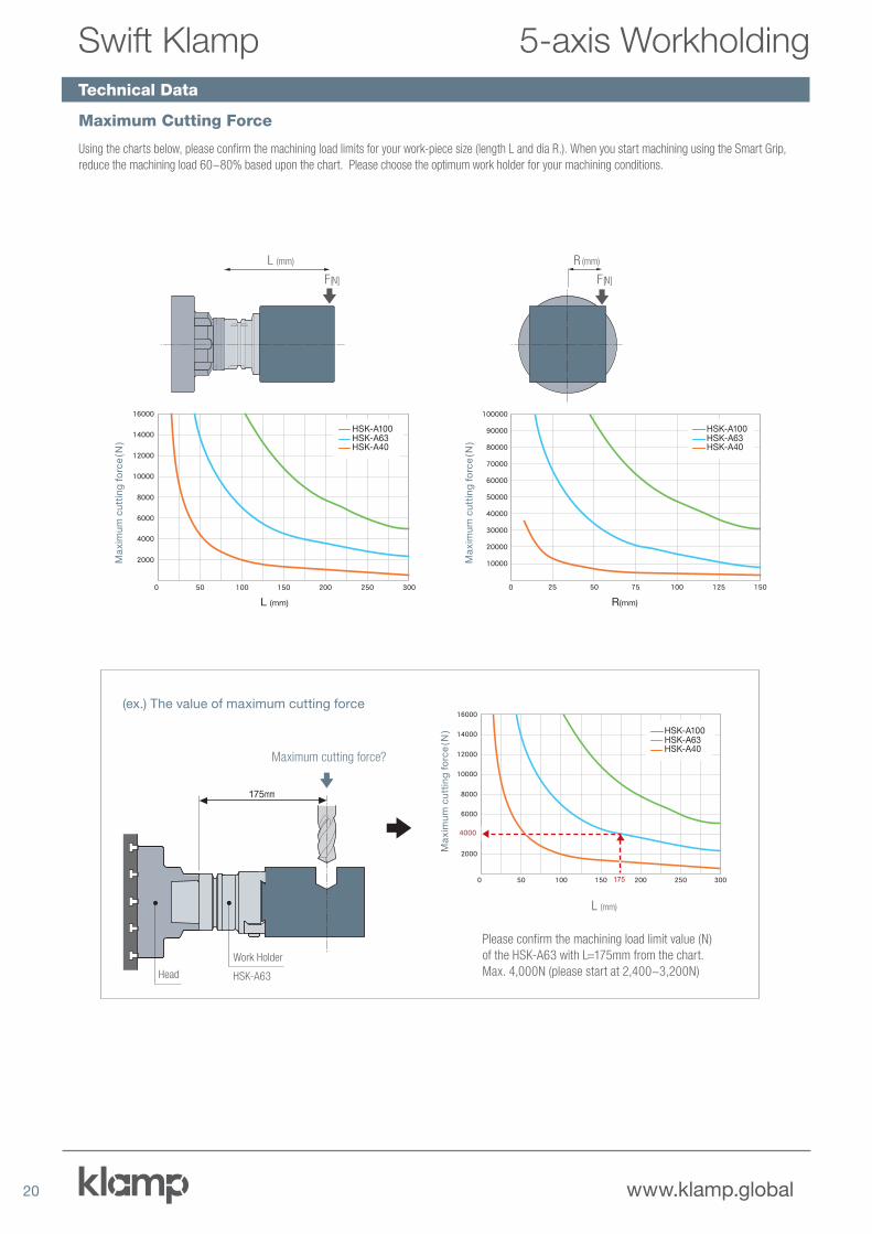
Technical Data
20 www.klamp.global
Using the charts below, please confirm the machining load limits for your work-piece size (length L and dia R.). When you start machining using the Smart Grip,
reduce the machining load 60~80% based upon the chart. Please choose the optimum work holder for your machining conditions.
Maximum cutting force?
175mm
Head
Work Holder
HSK-A63
(ex.) The value of maximum cutting force
Please confirm the machining load limit value (N)
of the HSK-A63 with L=175mm from the chart.
Max. 4,000N (please start at 2,400~3,200N)
L (mm)
16000
14000
12000
10000
8000
HSK-A100HSK-A63HSK-A40
6000
4000
2000
0 50 100 150 200 250 300
4000
175
16000
14000
12000
10000
8000
HSK-A100HSK-A63HSK-A40
6000
4000
2000
0 50 100 150 200 250 300
L (mm)
HSK-A100HSK-A63HSK-A40
HSK-A100HSK-A63HSK-A40
F [N]
Ma
xim
um
cu
ttin
g f
orc
e ( N
)
R (mm)
100000
90000
80000
70000
60000
50000
40000
30000
20000
10000
0 25 50 75 100 125 150
HSK-A100HSK-A63HSK-A40
R(mm)
HSK-A100HSK-A63HSK-A40
F [N]
Ma
xim
um
cu
ttin
g f
orc
e ( N
)
Ma
xim
um
cu
ttin
g f
orc
e ( N
)
L (mm)
Maximum Cutting Force
5-axis WorkholdingSwift Klamp

EUROPEKITAGAWA EUROPE LTD. (UK)t +44 1725 514 010 f +44 1725 514 001
KITAGAWA EUROPE GmbH (Germany)t +49 210 212 37800 f +49 210 212 37869
KITAGAWA EUROPE (Czech Republic)t +420 603 856 122
KITAGAWA EUROPE (Hungary)t +36 30 510 3550
KITAGAWA EUROPE (Poland)t +48 32 749 59 18
KITAGAWA EUROPE (Romania)t +40 727 770 329
KITAGAWA EUROPE (Slovenia/Croatia)t +385 99 216 1940
AMERICAKITAGAWA – NORTHTECH INC.t +1 847 310 8787 f +1 847 310 9484
ASIAKITAGAWA PVT LTD. (India)t +91 80 2976 5200 f +91 80 2976 5205
KITAGAWA IRON WORKS CO., LTD. (Japan)t +81 847 40 0526 f +81 847 450 8911
KITAGAWA IRON WORKS CO., LTD. (China)t +86 21 6295 5772 f +86 21 6295 5792
KITAGAWA CO., LTD. (Thailand)t +66 2 712 7479 f +66 2 712 7481
DEAMARK LIMITED (Taiwan)t +886 2 2393 1221 f +886 2 2395 1231
KITAGAWA CO., LTD. (Korea)t +82 2 2026 2222 f +82 2 2026 2113
MIDDLE EASTLOMAS MIDDLE EAST (U.A.E)t +971 6 551 6551
OCEANIADIMAC TOOLING PTY. LTD. (Australia)t +61 3 9561 6155 f +61 3 9561 6705
Unit 1, The Headlands, Downton, Salisbury, Wiltshire, SP5 3JJ, UK
www.kitagawa.global/en
Borsigstrasse 3, 40880 Ratingen, Germany
www.kitagawa.global/de
Lysicka 3, 621 00 Brno
www.kitagawa.global/cz
Déry T. u. 5. H-9024 Gyor
www.kitagawa.global/hu
44-240 Zory, ul. Niepodległosci 3, Poland
www.kitagawa.global/pl
Heliului 15, Bucharest 1, 013991, Romania
www.kitagawa.global/ro
Pantovcak 24, HR-10000 Zagreb
www.kitagawa.global/de
301 E. Commerce Dr, Scaumburg, IL. 60173, USA
www.kitagawa.us
Plot No. 15, 4th Phase, Bommasandra Industrial Area, Bommasandra
Jigani Link Road, Bangalore - 560 099
www.kitagawa.global/in
77-1 Motomachi, Fuchi-shi, Hiroshima-pref. 726-8610, Japan
www.kitagawa.com
Room 1315 13F Building B, Far East International Plaza,
No. 317 Xian Xia Road, Chang Ning, Shanghai, 20051, China
9th FL, Home Place Office Building, 283/43 Sukhumvit, 55Rd.
(Thonglor 13), Klongtopn-Nua, Wattana, Bangkok 10110, Thailand
No. 6, Lane 5, Lin Sen North Road, Taipei, Taiwan
www.demark.com/tw
803 Ho, B-Dong, Woolim Lion’s Valley, 371-28 Gasan-Dong,
Gumcheon-Cu, Seoul, Korea
www.kitagawa.co.kr
Lomas ME FZE,Unit Q3-107, SAIF Zone, PO Box 121499, Sharjah, UAE
www.kitagawa.global/ae
61-65 Geddes Street, Mulgrave, Victoria, 3170 Australia
www.dimac.co.au
www.klamp.global
Edition 1 – Jan 2019