435R-95 Control of Deflection in Concrete Structures - INTI · PDF fileControl of Deflection...
89
ACI 435R-95 became effective Jan. 1, 1995. Copyright © 2003, American Concrete Institute. All rights reserved including rights of reproduction and use in any form or by any means, including the making of copies by any photo process, or by electronic or mechanical device, printed, written, or oral, or recording for sound or visual reproduc- tion or for use in any knowledge or retrieval system or device, unless permission in writing is obtained from the copyright proprietors. ACI Committee Reports, Guides, Standard Practices, and Commentaries are intended for guidance in plan- ning, designing, executing, and inspecting construction. This document is intended for the use of individuals who are competent to evaluate the significance and limita- tions of its content and recommendations and who will accept responsibility for the application of the material it contains. The American Concrete Institute disclaims any and all responsibility for the stated principles. The Institute shall not be liable for any loss or damage arising therefrom. Reference to this document shall not be made in contract documents. If items found in this document are desired by the Architect/Engineer to be a part of the contract documents, they shall be restated in mandatory language for incorporation by the Architect/Engineer. 435R-1 Control of Deflection in Concrete Structures ACI 435R-95 (Reapproved 2000) (Appendix B added 2003) This report presents a consolidated treatment of initial and time-dependent deflection of reinforced and prestressed concrete elements such as simple and continuous beams and one-way and two-way slab systems. It presents the state of the art in practice on deflection as well as analytical methods for computer use in deflection evaluation. The introductory chapter and four main chapters are relatively independent in content. Topics include “Deflec- tion of Reinforced Concrete One-way Flexural Members,” “Deflection of Two-way Slab Systems,” and “Reducing Deflection of Concrete Members.” One or two detailed computational examples for evaluating the deflec- tion of beams and two-way action slabs and plates are given at the end of Chapters 2, 3, and 4. These computations are in accordance with the current ACI- or PCI-accepted methods of design for deflection. Keywords: beams; camber; code; concrete; compressive strength; cracking; creep; curvature; deflection; high-strength concrete; loss of prestress; modulus of rupture; moments of inertia; plates; prestressing; preten- sioned; post-tensioned; reducing deflection; reinforcement; serviceability; shrinkage; slabs; strains; stresses; tendons; tensile strength; time-depen- dent deflection. CONTENTS Chapter 1—Introduction, p. 435R-2 Chapter 2—Deflection of reinforced concrete one-way flexural members, p. 435R-3 2.1—Notation 2.2—General 2.3—Material properties 2.4—Control of deflection 2.5—Short-term deflection 2.6—Long-term deflection 2.7—Temperature-induced deflections Appendix A2, p. 435R-16 Example A2.1—Short- and long-term deflection of 4-span beam Example A2.2—Temperature-induced deflections Chapter 3—Deflection of prestressed concrete one-way flexural members, p. 435R-20 3.1—Notation 3.2—General 3.3—Prestressing reinforcement 3.4—Loss of prestress Reported by ACI Committee 435 Emin A. Aktan Anand B. Gogate Maria A. Polak Alex Aswad Jacob S. Grossman Charles G. Salmon Donald R. Buettner Hidayat N. Grouni * Andrew Scanlon Finley A. Charney C. T. Thomas Hsu Fattah A. Shaikh Russell S. Fling James K. Iverson Himat T. Solanki Amin Ghali Bernard L. Meyers Maher K. Tadros Satyendra K. Ghosh Vilas Mujumdar Stanley C. Woodson Edward G. Nawy Chairman A. Samer Ezeldin Secretary * Editor Acknowledgment is due to Robert F. Mast for his major contributions to the Report, and to Dr. Ward R. Malisch for his extensive input to the various chapters. The Committee also acknowledges the processing, checking, and editorial work done by Kristi A. Latimer of Rutgers University.
Transcript of 435R-95 Control of Deflection in Concrete Structures - INTI · PDF fileControl of Deflection...

ACI Committee Reports, Guides, Standard Practices,and Commentaries are intended for guidance in plan-ning, designing, executing, and inspecting construction.This document is intended for the use of individuals whoare competent to evaluate the significance and limita-tions of its content and recommendations and who willaccept responsibility for the application of the materialit contains. The American Concrete Institute disclaimsany and all responsibility for the stated principles. TheInstitute shall not be liable for any loss or damagearising therefrom.
Reference to this document shall not be made incontract documents. If items found in this document aredesired by the Architect/Engineer to be a part of thecontract documents, they shall be restated in mandatorylanguage for incorporation by the Architect/Engineer.
Control of Deflection in Concrete Structures
ACI 435R-95(Reapproved 2000)
(Appendix B added 2003)
This report presents a consolidated treatment of initial and time-dependentdeflection of reinforced and prestressed concrete elements such as simple andcontinuous beams and one-way and two-way slab systems. It presents thestate of the art in practice on deflection as well as analytical methods forcomputer use in deflection evaluation. The introductory chapter and fourmain chapters are relatively independent in content. Topics include “Deflec-tion of Reinforced Concrete One-way Flexural Members,” “Deflection ofTwo-way Slab Systems,” and “Reducing Deflection of Concrete Members.”
One or two detailed computational examples for evaluating the deflec-tion of beams and two-way action slabs and plates are given at the end ofChapters 2, 3, and 4. These computations are in accordance with the currentACI- or PCI-accepted methods of design for deflection.
Keywords: beams; camber; code; concrete; compressive strength; cracking;creep; curvature; deflection; high-strength concrete; loss of prestress;modulus of rupture; moments of inertia; plates; prestressing; preten-sioned; post-tensioned; reducing deflection; reinforcement; serviceability;
shrinkage; slabs; strains; stresses; tendons; tensile strength; time-depen-dent deflection.
CONTENTS
Reported by ACI Committee 435
Emin A. Aktan Anand B. Gogate Maria A. Polak
Alex Aswad Jacob S. Grossman Charles G. Salmon
Donald R. Buettner Hidayat N. Grouni* Andrew Scanlon
Finley A. Charney C. T. Thomas Hsu Fattah A. Shaikh
Russell S. Fling James K. Iverson Himat T. Solanki
Amin Ghali Bernard L. Meyers Maher K. Tadros
Satyendra K. Ghosh Vilas Mujumdar Stanley C. Woodson
Edward G. NawyChairman
A. Samer EzeldinSecretary
*EditorAcknowledgment is due to Robert F. Mast for his major contributions to the Report, and to Dr. Ward R. Malisch for his extensive input to the various chapters.
The Committee also acknowledges the processing, checking, and editorial work done by Kristi A. Latimer of Rutgers University.
Chapter 1—Introduction, p. 435R-2
Chapter 2—Deflection of reinforced concrete one-way flexural members, p. 435R-3
2.1—Notation2.2—General2.3—Material properties2.4—Control of deflection2.5—Short-term deflection2.6—Long-term deflection2.7—Temperature-induced deflections
Appendix A2, p. 435R-16Example A2.1—Short- and long-term deflection of 4-span
beamExample A2.2—Temperature-induced deflections
Chapter 3—Deflection of prestressed concrete one-way flexural members, p. 435R-20
3.1—Notation3.2—General3.3—Prestressing reinforcement3.4—Loss of prestress
ACI 435R-95 became effective Jan. 1, 1995.Copyright © 2003, American Concrete Institute.All rights reserved including rights of reproduction and use in any form or by any
means, including the making of copies by any photo process, or by electronic ormechanical device, printed, written, or oral, or recording for sound or visual reproduc-tion or for use in any knowledge or retrieval system or device, unless permission inwriting is obtained from the copyright proprietors.
435R-1

435R-2 ACI COMMITTEE REPORT
dependent effects on deflection and presents a summary of
3.5—General approach to deformation considerations—Curvature and deflection
3.6—Short-term deflection and camber evaluation inprestressed beams
3.7—Long-term deflection and camber evaluation inprestressed beams
Appendix A3, p. 435R-42Example A3.1—Short- and long-term single-tee beam
deflectionsExample A3.2—Composite double-tee cracked beam
deflections
Chapter 4—Deflection of two-way slab systems,p. 435R-50
4.1—Notation4.2—Introduction4.3—Deflection calculation method for two-way slab
systems4.4—Minimum thickness requirements4.5—Prestressed two-way slab systems4.6—Loads for deflection calculation4.7—Variability of deflections4.8—Allowable deflections
Appendix A4, p. 435R-62Example A4.1—Deflection design example for long-term
deflection of a two-way slabExample A4.2—Deflection calculation for a flat plate
using the crossing beam method
Chapter 5—Reducing deflection of concrete members, p. 435R-66
5.l—Introduction5.2—Design techniques5.3—Construction techniques5.4—Materials selection5.5—Summary
References, p. 435R-70
Appendix B—Details of the section curvature method for calculating deflections, p. 435R-77
B1—IntroductionB2—BackgroundB3—Cross-sectional analysis outlineB4—Material propertiesB5—Sectional analysisB6—Calculation when cracking occursB7—Tension-stiffeningB8—Deflection and change in length of a frame memberB9—Summary and conclusionsB10—ExamplesB11—References
CHAPTER 1—INTRODUCTIONDesign for serviceability is central to the work of struc-
tural engineers and code-writing bodies. It is also essential tousers of the structures designed. Increased use of high-
strength concrete with reinforcing bars and prestressed rein-forcement, coupled with more precise computer-aided limit-state serviceability designs, has resulted in lighter and morematerial-efficient structural elements and systems. This inturn has necessitated better control of short-term and long-term behavior of concrete structures at service loads.
This report presents consolidated treatment of initial andtime-dependent deflection of reinforced and prestressedconcrete elements such as simple and continuous beams andone-way and two-way slab systems. It presents current engi-neering practice in design for control of deformation anddeflection of concrete elements and includes methodspresented in “Building Code Requirements for ReinforcedConcrete (ACI 318)” plus selected other published approachessuitable for computer use in deflection computation. Designexamples are given at the end of each chapter showing how toevaluate deflection (mainly under static loading) and thuscontrol it through adequate design for serviceability. Thesestep-by-step examples as well as the general thrust of the reportare intended for the non-seasoned practitioner who can, in asingle document, be familiarized with the major state of prac-tice approaches in buildings as well as additional condensedcoverage of analytical methods suitable for computer use indeflection evaluation. The examples apply AC1 318 require-ments in conjunction with PCI methods where applicable.
The report replaces several reports of this committee inorder to reflect more recent state of the art in design. Thesereports include ACI 435.2R, “Deflection of ReinforcedConcrete Flexural Members,” ACI 435.1R, “Deflection ofPrestressed Concrete Members,” ACI 435.3R, “AllowableDeflections,” ACI 435.6R, “Deflection of Two-Way Rein-forced Concrete Floor Systems,” and 435.5R, “Deflection ofContinuous Concrete Beams.”
The principal causes of deflections taken into account inthis report are those due to elastic deformation, flexuralcracking, creep, shrinkage, temperature and their long-termeffects. This document is composed of four main chapters,two to five, which are relatively independent in content.There is some repetition of information among the chaptersin order to present to the design engineer a self-containedtreatment on a particular design aspect of interest.
Chapter 2, “Deflection of Reinforced Concrete One-WayFlexural Members,” discusses material properties and theireffect on deflection, behavior of cracked and uncrackedmembers, and time-dependent effects. It also includes therelevant code procedures and expressions for deflectioncomputation in reinforced concrete beams. Numericalexamples are included to illustrate the standard calculationmethods for continuous concrete beams.
Chapter 3, “Deflection of Prestressed Concrete One-WayMembers,” presents aspects of material behavior pertinent topretensioned and post-tensioned members mainly forbuilding structures and not for bridges where more preciseand detailed computer evaluations of long-term deflectionbehavior is necessary, such as in segmental and cable-stayedbridges. It also covers short-term and time-dependent deflectionbehavior and presents in detail the Branson effectivemoment of inertia approach (Ie) used in ACI 318. It gives indetail the PCI Multipliers Method for evaluating time-

DEFLECTION IN CONCRETE STRUCTURES 435R-3
various other methods for long-term deflection calculationsas affected by loss of prestressing. Numerical examples aregiven to evaluate short-term and long-term deflection intypical prestressed tee-beams.
Chapter 4, “Deflection of Two-way Slab Systems,” coversthe deflection behavior of both reinforced and prestressedtwo-way-action slabs and plates. It is a condensation of ACIDocument 435.9R, “State-of-the-Art Report on Control ofTwo-way Slab Deflections,” of this Committee. This chaptergives an overview of classical and other methods of deflectionevaluation, such as the finite element method for immediatedeflection computation. It also discusses approaches fordetermining the minimum thickness requirements for two-way slabs and plates and gives a detailed computationalexample for evaluating the long-term deflection of a two-way reinforced concrete slab.
Chapter 5, “Reducing Deflection of Concrete Members,”gives practical and remedial guidelines for improving andcontrolling the deflection of reinforced and prestressed concreteelements, hence enhancing their overall long-term serviceability.
Appendix B presents a general method for calculating thestrain distribution at a section considering the effects of anormal force and a moment caused by applied loads,prestressing forces, creep, and shrinkage of concrete, andrelaxation of prestressing steel. The axial strain and thecurvature calculated at various sections can be used to calculatedisplacements. This comprehensive analysis procedure is foruse when the deflections are critical, when maximumaccuracy in calculation is desired, or both.
The curvatures and the axial strains at sections of acontinuous or simply supported member can be used tocalculate the deflections and the change of length of themember using virtual work. The equations that can be usedfor this purpose are given in Appendix B. The appendixincludes examples of the calculations and a flowchart thatcan be used to automate the analytical procedure.
It should be emphasized that the magnitude of actualdeflection in concrete structural elements, particularly inbuildings, which are the emphasis and the intent of thisReport, can only be estimated within a range of 20-40 percentaccuracy. This is because of the large variability in the prop-erties of the constituent materials of these elements and thequality control exercised in their construction. Therefore, forpractical considerations, the computed deflection values inthe illustrative examples at the end of each chapter ought tobe interpreted within this variability.
In summary, this single umbrella document gives designengineers the major tools for estimating and thereby controllingthrough design the expected deflection in concrete buildingstructures. The material presented, the extensive reference listsat the end of the Report, and the design examples will help toenhance serviceability when used judiciously by the engineer.Designers, constructors, and codifying bodies can draw on thematerial presented in this document to achieve serviceabledeflection of constructed facilities.
CHAPTER 2—DEFLECTION OF REINFORCED CONCRETE ONE-WAY FLEXURAL MEMBERS*
2.1—NotationA = area of concrete sectionAc = effective concrete cross section after cracking, or
area of concrete in compressionAs = area of nonprestressed steelAsh = shrinkage deflection multiplierb = width of the sectionc = depth of neutral axisCc,(CT)= resultant concrete compression (tension) forceCt = creep coefficient of concrete at time t daysCu = ultimate creep coefficient of concreted = distance from the extreme compression fiber to
centroid of tension reinforcementD = dead load effectEc = modulus of elasticity of concrete
Ec = age-adjusted modulus of elasticity of concrete at time t
Es = modulus of elasticity of nonprestressed reinforcing steel
EI = flexural stiffness of a compression memberfc′ = specified compressive strength of concretefct, ft′ = splitting tensile strength of concretefr = modulus of rupture of concretefs = stress in nonprestressed steelfy = specified yield strength of nonprestressed reinforc-
ing steelh = overall thickness of a memberI = moment of inertia of the transformed sectionIcr = moment of inertia of the cracked section trans-
formed to concreteIe = effective moment of inertia for computation of
deflectionIg = moment of inertia for gross concrete section about
centroidal axis, neglecting reinforcementK = factor to account for support fixity and load
conditionsKe = factor to compute effective moment of inertia for
continuous spansksh = shrinkage deflection constantK(subscript)=modification factors for creep and shrinkage
effectsl = span lengthL = live load effectM(subscript)= bending momentMa = maximum service load moment (unfactored) at
stage deflection is completedMcr = cracking momentMn = nominal moment strengthMo = midspan moment of a simply supported beamP = axial forcet = timeTs = force in steel reinforcementwc = specified density of concreteyt = distance from centroidal axis of gross section,
neglecting reinforcement, to extreme fiber in tensionα = thermal coefficientγc = creep modification factor for nonstandard
conditionsγsh = shrinkage modification factor for nonstandard
*Principal authors: A. S. Ezeldin and E. G. Nawy.

435R-4 ACI COMMlTTEE REPORT
strain in extreme compression fiber of amember
= conditions4 = cross section curvature
= strength reduction factor#) -cracked = curvature of a cracked member4 mean = mean curvature4 uncracked = curvature of an uncracked member% =
%('SHh =hH)u =
P =
pb =
P’ =
E =8 =6 =CTSL =
‘LT=
s,_T =
ssh=
ii =SMS
4=
strain in nonprestressed steelshrinkage strain of concrete at time, t daysultimate shrinkage strain of concretenonprestressed tension reinforcement ratioreinforcement ratio producing balanced strainconditionsreinforcement ratio for nonprestressed com-pression steel
*fAtJ =*fJtl to> =
time dependent deflection factorelastic deflection of a beamadditional deflection due to creepinitial deflection due to live loadtotal long term deflectionincrease in deflection due to long-term effectsadditional deflection due to shrinkageinitial deflection due to sustained loady-coordinate of the centroid of the age-adjusted section, measured downward fromthe centroid of the transformed section at tostress increment at time to daysstress increment from zero at time to to itsfull value at time t
(*+)creep = additional curvature due to creep(A@shrinkage = additional curvature due to shrinkage3, = deflection multiplier for long term deflectionIr = multiplier to account for high-strength con-
crete effect on long-term deflection77 = correction factor related to the tension and
compression reinforcement, CEB-FIP
2.2-General2.2.1 Introduction-Wide availability of personal com-
puters and design software, plus the use of higherstrength concrete with steel reinforcement has permittedmore material efficient reinforced concrete designsproducing shallower sections. More prevalent use ofhigh-strength concrete results in smaller sections, havingless stiffness that can result in larger deflections.Consquently, control of short-term and long-termdeflection has become more critical.
In many structures, deflection rather than stresslimitation is the controlling factor. Deflection com-putations determine the proportioning of many of thestructural system elements. Member stiffness is also afunction of short-term and long-term behavior of theconcrete. Hence, expressions defining the modulus ofrupture, modulus of elasticity, creep, shrinkage, andtemperature effects are prime parameters in predictingthe deflection of reinforced concrete members.
2.2.2 Objectives-This chapter covers the initial and
time-dependent deflections at service load levels understatic conditions for one-way non-prestressed flexuralconcrete members. It is intended to give the designerenough basic background to design concrete elementsthat perform adequately under service loads, taking intoaccount cracking and both short-term and long-termdeflection effects.
While several methods are available in the literaturefor evaluation of deflection, this chapter concentrates onthe effective moment of inertia method in Building CodeRequirements for Reinforced Concrete (ACI 318) and themodifications introduced by ACI Committee 435. It alsoincludes a brief presentation of several other methodsthat can be used for deflection estimation computations.
2.2.3 Significance of defection observation-Theworking stress method of design and analysis used priorto the 1970s limited the stress in concrete to about 45percent of its specified compressive strength, and thestress in the steel reinforcement to less than 50 percentof its specified yield strength. Elastic analysis was appliedto the design of reinforced concrete structural frames aswell as the cross-section of individual members. Thestructural elements were proportioned to carry thehighest service-level moment along the span of the mem-ber, with redistribution of moment effect often largelyneglected. As a result, stiffer sections with higher reservestrength were obtained as compared to those obtained bythe current ultimate strength approach (Nawy, 1990).
With the improved knowledge of material propertiesand behavior, emphasis has shifted to the use of high-strength concrete components, such as concretes withstrengths in excess of 12,000 psi (83 MPa). Consequently,designs using load-resistance philosophy have resulted insmaller sections that are prone to smaller serviceabilitysafety margins. As a result, prediction and control ofdeflections and cracking through appropriate design havebecome a necessary phase of design under service loadconditions.
Beams and slabs are rarely built as isolated members,but are a monolithic part of an integrated system. Exces-sive deflection of a floor slab may cause dislocations inthe partitions it supports or difficulty in leveling furnitureor fixtures. Excessive deflection of a beam can damage apartition below, and excessive deflection of a spandrelbeam above a window opening could crack the glasspanels. In the case of roofs or open floors, such as topfloors of parking garages, ponding of water can result.For these reasons, empirical deflection control criteriasuch as those in Table 2.3 and 2.4 are necessary.
Construction loads and procedures can have a signi-ficant effect on deflection particularly in floor slabs.Detailed discussion is presented in Chapter 4.
2.3-Material propertiesThe principal material parameters that influence con-
crete deflection are modulus of elasticity, modulus ofrupture, creep, and shrinkage. The following is a presen-tation of the expressions used to define these parameters

DEFLECTION IN CONCRETE STRUCTURES 435R-5
a(12
retu
w
thOf
2w1o
1np3mco(8
2pnevla
eaeststcstnxcr5thtesi
Nsc2
swpi
Mmcvg
w
wp1gfcDpa
tcMfw
mpuu
Mfspmupa
s recommended by ACI 318 and its Commentary989) and ACI Committees 435 (1978), 363 (1984), and
09 (1982).2.3.1 Concrete modulus of rupture-AC1 318 (1989)
commends Eq. 2.1 for computing the modulus of rup-re of concrete with different densities:
fr = 7.5 X K, psi (2.1)(0.623 X g, MPa)
here X = 1.0 for normal density concrete [145 to 150pcf (2325 to 2400 kg/m3)]
= 0.85 for semi low-density [ll0-145 pcf(1765 to 2325 kg/m3)]
= 0.75 for low-density concrete [90 to 110 pcf(1445 to 1765 kg/m3)]
Eq. 2.1 is to be used for low-density concrete whene tensile splitting strength, fct, is not specified.therwise, it should be modified by substituting fc t/6.7 forl, but the value of fct/6.7 should not exceed \ /
_f c '.
ACI Committee 435 (1978) recommended using Eq..2 for computing the modulus of rupture of concreteith densities (wc) in the range of 90 pcf (1445 kg/m3) to45 pcf (2325 kg/m3). This equation yields higher valuesf fro
fr = 0.65 ,/c, psi (2.2)(0.013 ,/G, MPa)
The values reported by various investigators ACI 363,984) for the modulus of rupture of both low-density andormal density high-strength concretes [more than 6,000si (42 MPa)] range between 7.5 K and 12 g. ACI63 (1992) stipulated Eq. 2.3 for the prediction of theodulus of rupture of normal density concretes havingmpressive strengths of 3000 psi (21 MPa) to 12,000 psi3 MPa).
fi = 11.7 K, psi (2.3)
The degree of scatter in results using Eq. 2.1, 2.2 and.3 is indicative of the uncertainties in predicting com-uted deflections of concrete members. The designereeds to exercise judgement in sensitive cases as to whichxpressions to use, considering that actual deflectionalues can vary between 25 to 40 percent from the calcu-ted values.2.3.2 Concrete modulus of elasticity -The modulus of
lasticity is strongly influenced by the concrete materialsnd proportions used. An increase in the modulus oflasticity is expected with an increase in compressiverength since the slope of the ascending branch of theress-strain diagram becomes steeper for higher-strengthoncretes, but at a lower rate than the compressiverength. The value of the secant modulus of elasticity forormal-strength concretes at 28 days is usually around 4 lo6 psi (28,000 MPa), whereas for higher-strength con-etes, values in the range of 7 to 8 x lo6 psi (49,000 to6,000 MPa) have been reported. These higher values ofe modulus can be used to reduce short-term and long-rm deflection of flexural members since the compres-ve strength is higher, resulting in lower creep levels.
ormal strength concretes are those with compressivetrengths up to 6,000 psi (42 MPa) while higher strengthoncretes achieve strength values beyond 6,000 and up to0,000 psi (138 MPa) at this time.
ACI 435 (1963) recommended the following expres-ion for computing the modulus of elasticity of concretesith densities in the range of 90 pcf (1445 kg/m3) to 155cf (2325 kg/m3) based on the secant modulus at 0.45 fc’ntercept
E = 33 MQ*~ K, psi (2.4)(ocO43. )$) 1.5
c g9 MPa)
For concretes in the strength range up to 6000 psi (42Pa), the ACI 318 empirical equation for the secantodulus of concrete EC of Eq. 2.4 is reasonably appli-
able. However, as the strength of concrete increases, thealue of EC could increase at a faster rate than thatenerated by Eq. 2.4 (EC = wclo5 K), thereby under-
estimating the true EC value. Some expressions for E,applicable to concrete strength up to 12,000 psi (83 MPa)are available. The equation developed by Nilson (Carra-squillo, Martinez, Ngab, et al, 1981, 1982) for normal-
eight concrete of strengths up to 12,000 psi (83 MPa)and light-weight concrete up to 9000 psi (62 MPa) is:
EC = (40,000 K + l,OOO,OOO) 2
( 1
1. i 1
1.5
, psi (2.5)
(3.32 K + 6895) & , MPa
here w, is the unit weight of the hardened concrete incf, being 145 lb/ft3 for normal-weight concrete and 100 -20 lb/ft for sand-light weight concrete. Other investi-ations report that as fi approaches 12,000 psi (83 MPa)or normal-weight concrete and less for lightweight con-rete, Eq. 2.5 can underestimate the actual value of E,.eviations from predicted values are highly sensitive toroperties of the coarse aggregate such as size, porosity,nd hardness.
Researchers have proposed several empirical equa-ions for predicting the elastic modulus of higher strengthoncrete (Teychenne et al, 1978; Ahmad et al, 1982;artinez, et al, 1982). ACI 363 (1984) recommended the
ollowing modified expression of Eq. 2.5 for normal-eight concrete:
EC
= 40,000 g + l,OOO,OOO , psi (2.6)
Using these expressions, the designer can predict aodulus of elasticity value in the range of 5.0 to 5.7 x lo6
si (35 to 39 x lo3 MPa) for concrete design strength ofp to 12,000 psi (84 MPa) depending on the expressionsed.
When very high-strength concrete [20,000 psi (140Pa) or higher] is used in major structures or when de-
ormation is critical, it is advisable to determine thetress-strain relationship from actual cylinder com-ression test results. In this manner, the deduced secantodulus value of EC at an fc = 0.45 fi intercept can be
sed to predict more accurately the value of EC for thearticular mix and aggregate size and properties. Thispproach is advisable until an acceptable expression is

435R-6 ACI COMMITTEE REPORT
available to the designer (Nawy, 1990).2.3.3 Steel reinforcement modulus of elasticity-AC1 318
specifies using the value Es = 29 x 106 psi (200 x 106MPa) for the modulus of elasticity of nonprestressed re-inforcing steel.
2.3.4 Concrete creep and shrinkage-Deflections arealso a function of the age of concrete at the time ofloading due to the long-term effects of shrinkage andcreep which significantly increase with time. ACI 318-89does not recommend values for concrete ultimate creepcoefficient Cu and ultimate shrinkage strain (E&.However, they can be evaluated from several equationsavailable in the literature (ACI 209, 1982; Bazant et al,1980; Branson, 1977). ACI 435 (1978) suggested that theaverage values for C, and (QU can be estimated as 1.60and 400 x 106, respectively. These values correspond tothe following conditions:
- 70 percent average relative humidity- age of loading, 20 days for both moist and steam
cured concrete- minimum thickness of component, 6 in. (152 mm)Table 2.1 includes creep and shrinkage ratios at dif-
ferent times after loading.
Table 2.1 - Creep and shrinkage ratios from age 60 days to the indicated concrete age (Branson, 1977)
Creep, shrinkage ratios
C* JCU
(ES,, )t /(ES,, ), -M.C.
(f, )f /(E, ), -S.C.
Concrete age
2 months 3 months 6 months 1 year 2 years > 5 years
0.48 0.56 0.68 0.77 0.84 1.00
0.46 0.60 0.77 0.88 0.94 1.00
0.36 0.49 0.69 0.82 0.91 1.00
M.C. = Moist curedS.C. = Steam curd
ACI 209 (1971, 1982,1992) recommended a time-de-pendent model for creep and shrinkage under standardconditions as developed by Branson, Christianson, andKripanarayanan (1971,1977). The term “standard condi-tions” is defined for a number of variables related tomaterial properties, the ambient temperature, humidity,and size of members. Except for age of concrete at loadapplication, the standard conditions for both creep andshrinkage are
a)
b)c )d)e )f )
Age of concrete at load applications = 3 days(steam), 7 days (moist)Ambient relative humidity = 40 percentMinimum member thickness = 6 in. (150 mm)Concrete consistency = 3 in. (75 mm)Fine aggregate content = 50 percentAir content = 6 percent
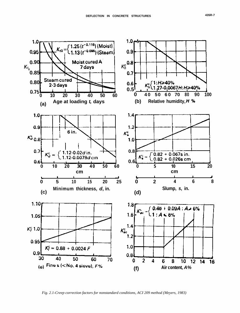
The coefficient for creep at time t (days) after loadapplication, is given by the following expression:
/ CO.6 \Ct = IlO’+ to.6J cu (2.7)
where Cu, = 2.35 YCRyCR = Khc Kdc K”’ KF K,,’ KIOc = 1 for stan-
dard conditions.
Each K coefficient is a correction factor for conditionsother than
Khc =K/ =KS” =KC =
C =
K;: =
standard as follows:relative humidity factorminimum member thickness factorconcrete consistency factorfine aggregate content factorair content factorage of concrete at load applications factor
Graphic representations and general equations for themodification factors (K-values) for nonstandard condi-tions are given in Fig. 2.1 (Meyers et al, 1983).
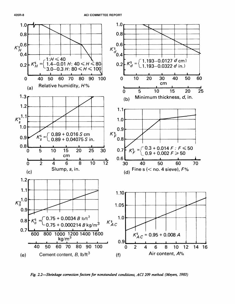
For moist-cured concrete, the free shrinkage strainwhich occurs at any time t in days, after 7 days fromplacing the concrete
(2.8)
and for steam cured concrete, the shrinkage strain at anytime t in days, after l-3 days from placing the concrete
where (E&, Mar = 780 x 10-6 yshxsh = Kh” Kds K; Kbs K,,”
= 1 for standard conditions
(2.9)
Each K coefficient is a correction factor for other thanstandard conditions. All coefficients are the same as de-fined for creep except K,9, which is a coefficient forcement content. Graphic representation and generalequations for the modification factors for nonstandardconditions are given in Fig. 2.2 (Meyers et al, 1983). The
above procedure, using standard and correction equationsand extensive experimental comparisons, is detailed inBranson (1977).Limited information is available on the shrinkage be-havior of high-strength concrete [higher than 6,000 psi(41 MPa)], but a relatively high initial rate of shrinkagehas been reported (Swamy et al, 1973). However, afterdrying for 180 days the difference between the shrinkageof high-strength concrete and lower-strength concreteseems to become minor. Nagataki (1978) reported thatthe shrinkage of high-strength concrete containing high-range water reducers was less than for lower-strengthconcrete.
On the other hand, a significant difference was re-ported for the ultimate creep coefficient between high-
DEFLECTION IN CONCRETE STRUCTURES 435R-7
0
0Kt0
0
0
.90
.85
.80
0 10 20 30 40 50 60
(a) Age at loading days
061W l
0 10 20 30 4 0 50 60cm
Kch
0.5 k 1 1 1 1 10
l
4 0 50 6 0 70 80 90 100(b) Relative humidity, kf o/o
0.8
0.6 0
5 10 15 20
cm
0 5 10 l
15 20 25
(c)Minimum thickness, d, in.
0 2 4 6 8
(d)Slump, s, in.
(f) Air content, A%
Fig. 2.1-Creep correction factors for nonstandard conditions, ACI 209 method (Meyers, 1983)

DEFLECTION IN CONCRETE STRUCTURES 435R-9
strength concrete and its normal strength counterpart.The ratio of creep strain to initial elastic strain undersustained axial compression, for high-strength concrete,may be as low as one half that generally associated withlow-strength concrete (Ngab et al, 1981; Nilson, 1985).
2.4-Control of deflectionDeflection of one-way nonprestressed concrete flex-
ural members is controlled by reinforcement ratio limita-tions, minimum thickness requirements, and span/deflec-tion ratio limitations.
2.4.1 Tension steel reinforcement ratio limitations-Onemethod to minimize deflection of a concrete member inflexure is by using a relatively small reinforcement ratio.Limiting values of ratio p, ranging fromare recommended by ACI 435 (1978), as shown in Table2.2. Other methods of deflection reduction are presentedin Chapter 5 of this report.
to
Table 2.2-Recommended tension reinforcement ratios for nonprestressed one-way members so that deflections willnormally be within acceptable limits (ACI 435, 1978)
Members
Not supporting or not attached to nonstruc-tural elements likely to be damaged by largedeflections
Cross section Normal weight concrete
Rectangular p 5 35 percent pb“T’ or box I% 5 40 percent Pb
Lightweight concrete
p S 30 percent pbpw S 35 percent pb
Supporting or attached to nonstructural ele-ments likely to be damaged by large deflec-lions
Rectangular“T or box
p I 25 percent pbp,,, 5 30 percent &,
p 5 20 percent pbpW 5 25 percent Pb
For continuous members, the positive region steel ratios only may be used. pl: Refers to the balanced steel ratio based on ultimate strength.
2.4.2 Minimum thickness limitations-Deflections ofbeams and one way slabs supporting usual loads in build-ings, where deflections are not of concern, are normallysatisfactory when the minimum thickness provisions inTable 2.3 are met or exceeded. This table (ACI 318,1989) applies only to members that are not supporting ornot attached to partitions or other construction likely tobe damaged by excessive deflections. Values in Table 2.3
Table 2.3-Minimum thickness of nonprestressed beams and one-way slabs unless deflections are computed (ACI318, 1989)
Minimum thickness, h
Member
Simply supported One end continuous Both ends continuous Cantilever
Members not supporting or attached to partitions or other construction likely to be damaged by largedeflections.
Solid one-way slabs
Beams or ribbed one-way slabs
et20
e/16
l/24
ei18.5
et28
erzi
e/lo
ei8
e = Span lengthValues given shall be used directly for members with normal weight concrete (w, = 145 pcf) and grade 60 reinforcement. For other conditions. the values
shall be modified as follows:
a) For structural lightweight concrete having unit weights in the range 90-120 lb per cu ft. the values shall be multiplied by (1.65 - 0.005 WJ but not less than
1.09, where wC is the unit weight in lb per cu ft.
b) Forf, other than 60,000 psi, the values shall be multiplied by (0.4 + fJlOO,oOO).
have been modified by ACI 435 (1978) and expanded inTable 2.4 to include members that are supporting or at-
tached to non-structural elements likely to be damagedby excessive deflections. The thickness may be decreasedwhen computed deflections are shown to be satisfactory.Based on a large number of computer studies, Grossman(1981, 1987) developed a simplified expression for theminimum thickness to satisfy serviceability requirements(Eq. 4.17, Chapter 4).2.4.3 Computed deflection limitations--The allowablecomputed deflections specified in ACI 318 for one-waysystems are given in Table 2.5, where the span-deflection
ratios provide for a simple set of allowable deflections.Where excessive deflection may cause damage to non-structural or other structural elements, only that part ofthe deflection occurring after the construction of thenonstructural elements, such as partitions, needs to beconsidered. The most stringent span-deflection limit ofl/480 in Table 2.5 is an example of such a case. Whereexcessive deflection may result in a functional problem,such as visual sagging or ponding of water, the totaldeflection should be considered.2.5-Short-term deflection2.5.1 Untracked members-Gross moment of inertia Ig
-When the maximum flexural moment at service load in

435R-10 ACI COMMITTEE REPORT
Table 2.4-Minimum thickness of beams and one-way slabs used in roof and floor construction (ACI 435, 1978)
Members not supporting or not attached to nonstructural Members supporting or attached to nonstructural elementselements likely to be damaged by large deflections likely to be damaged by large deflection
Simply One end Both ends Simply One end Both endsMember supported continuous continuous Cantilever supported continuous continuous Cantilever
Roof slab l/22 l/28 1135 U9 l/14 VI8 l/22 115.5
Floor slab, and l/18 V23 l/28 l/7 1112 l/15 l/19 USroof beam orribbed roofslab
Floor beam or l/14 1118 l/21 l/5.5 l/10 lfl3 l/16 114ribbed floorslab
Table 2.5-Maximum permissible computed beflections (ACI 318, 1989)
Type of member Deflection to be considered
Flat roofs not supporting or attached to nonstructural Immediate deflection due to live load Lelements likely to be damaged by large deflections
Floors not supporting or attached to nonstructural elements Immediate deflection due to live load Llikely to be damaged by large deflections
Roof or floor construction supporting or attached to That part of the total deflection occurring afternonstructural elements likely to be damaged by large attachment of nonstructural elements (sum ofdeflections the long-time deflection due to all sustained
Roof or floor construction supporting or attached to loads and the innediate deflection due to any
nonstructural elements not likely to be damaged by large additional live l o a d )
deflect ions
Deflection limitation
e’180
e360
e#480
40240
* Limit not intended to safeguard against ponding. Ponding should be checked by suitable calculations of deflection, including added deflections due to pondedwater, and considering long-term effects of all sustained loads, camber, construction tolerances, and reliability of provisions for drainage.
t Long-time deflection shall be determined in accordance with 9.5.2.5 or 9.5.4.2 but may be reduced by amount of deflection calculated to occur beforeattachment of nonstructural elements. This amount shall be determined on basis of accepted engineering data relating to time-deflection characteristics ofmembers similar to those being considered.
$ Limit may be exceeded if adequate measures are taken to prevent damage to supported or attached elements.9 But not greater than tolerance provided for nonstructural elements. Limit may be exceeded if camber is provided so that total deflection minus camber does
not exceed limit.
a beam or a slab causes a tensile stress less than themodulus of rupture,f, no flexural tension cracks developat the tension side of the concrete element if the memberis not restrained or the shrinkage and temperature tensilestresses are negligible. In such a case, the effectivemoment of inertia of the uncracked transformed section,II, is applicable for deflection computations. However, fordesign purposes, the gross moment of inertia, I@neglecting the reinforcement contribution, can be usedwith negligible loss of accuracy. The combination of ser-vice loads with shrinkage and temperature effects due toend restraint may cause cracking if the tensile stress inthe concrete exceeds the modulus of rupture. In suchcases, Section 2.5.2 applies.
The elastic deflection for noncracked members canthus be expressed in the following general form
6=KMIZEcI,
(2.10)
where K is a factor that depends on support fixity and
loading conditions. M is the maximum flexural momentalong the span. The modulus of elasticity EC can be ob-tained from Eq. 2.4 for normal-strength concrete or Eq.2.5 for high-strength concrete.
2.5.2 Cracked members-Effective moment of inertia Ie-Tension cracks occur when the imposed loads causebending moments in excess of the cracking moment, thusresulting in tensile stresses in the concrete that are higherthan its modulus of rupture. The cracking moment, MC,.,may be computed as follows:
(2.11)
where yt is the distance from the neutral axis to thetension face of the beam, and f, is the modulus ofrupture of the concrete, as expressed by Eq. 2.1.
Cracks develop at several sections along the memberlength. While the cracked moment of inertia, Ic,., appliesto the cracked sections, the gross moment of inertia, Ig,applies to the uncracked concrete between these sections.

DEFLECTION IN CONCRETE STRUCTURES 435R-11
Several methods have been developed to estimate thevariations in stiffness caused by cracking along the span,These methods provide modification factors for the flex-ural rigidity E I (Yu et al, 1960), identify an effectivemoment of inertia (Branson, 1963), make adjustments tothe curvature along the span and at critical sections(Beeby, 1968), alter the M/ I ratio (CEB, 1968), or use asection-curvature incremental evaluation (Ghali, et al,1986, 1989).
The extensively documented studies by Branson (1977,1982, 1985) have shown that the initial deflections qoccurring in a beam or a slab after the maximummoment M, has exceeded the cracking moment M,, canbe evaluated using an effective moment of inertia Z,instead of I in Eq. 2.10.
2.5.2.1 Simply supported beams-ACI 318-89 r e -quires using the effective moment of inertia Z, proposedby Branson. This approach was selected as being suffi-ciently accurate to control deflections in reinforced andprestressed concrete structural elements. Branson’sequation for the effective moment of inertia Z,, for shortterm deflections is as follows
where%, =Ma =
Cracking momentMaximum service load moment (unfactored)at the stage for which deflections are beingconsideredGross moment of inertia of sectionMoment of inertia of cracked transformedsection
The two moments of inertia Zg and Z,, are based onthe assumption of bilinear load-deflection behavior (Fig.3.19, Chapter 3) of cracked section. Z, provides a trans-
ition between the upper and the lower bounds of Z andI,,., respectively, as a function of the level of cracking,expressed as i&/Ma. Use of Z, as the resultant of theother two moments of inertia should essentially givedeflection values close to those obtained using the bi-linear approach. The cracking moment of inertia, I,, canbe obtained from Fig. 2.3 (PCA, 1984). Deflections should be computed for each load level using Eq. 2.12,such as dead load and dead load plus live load. Thus, theincremental deflection such as that due to live loadalone, is computed as the difference between these valuesat the two load levels. Z, may be determined using M,, atthe support for cantilevers, and at the midspan for simplespans. Eq. 2.12 shows that I, is an interpolation betweenthe well-defined limits of Z and I,,. This equation hasbeen recommended by ACI Committee 435 since 1966and has been used in ACI 318 since 1971, the PCI Hand-book since 1971, and the AASHTO Highway Bridge Speci-fications since 1973. Detailed numerical examples usingthis method for simple and continuous beams, unshoredand shored composite beams are available in Branson(1977). The textbooks by Wang and Salmon (1992), andby Nawy (1990) also have an extensive treatment of thesubject.Eq. 2.12 can also be simplified to the following form:
Heavily reinforced members wiIl have an Z, approx-imately equal to Icr, which may in some cases (flangedmembers) be larger than Zg of the concrete section alone.For most practical cases, the calculated Z, will be lessthan Zg and should be taken as such in the design fordeflection control, unless a justification can be made forrigorous transformed section computations.
2.5.2.2 Continuous beams--For continuous mem-bers, ACI 318-89 stipulates that Z, may be taken as theaverage values obtained from 2.12 for the criticalpositive and negative moment sections. For prismaticmembers, Z, may be taken as the value obtained at mid-span for continuous spans. The use of midspan sectionproperties for continuous prismatic members is con-sidered satisfactory in approximate calculations primarilybecause the midspan rigidity including the effect ofcracking has the dominant effect on deflections (ACI435, 1978).
If the designer chooses to average the effectivemoment of inertia Z,, then according to ACI 318-89, thefollowing expression should be used:
I, = 0.5 4(m) + 0.25 (G(1) + h(2)) (2.14)
where the subscripts m, 1, and 2 refer to mid-span, andthe two beam ends, respectively.
Improved results for continuous prismatic memberscan, however, be obtained using a weighted average aspresented in the following equations:
For beams continuous on both ends,
4 = 0.70 Ze@) + 0.15 (I,(,) + h(2)) G95a)
For beams continuous on one end only,
Z, = 0.85 I+) + 0.15 (I,(,)) (2.15b)
When Z, is calculated as indiuated in the previous dis-cussion, the deflection can be obtained using the mo-ment-area method (Fig. 3.9, Chapter 3) taking the mo-
ment-curvature (rotation) into consideration or usingnumerical incremental procedures. It should be statedthat the Z, value can also be affected by the type ofloading on the member (Al-Zaid, 1991), i.e. whether theload is concentrated or distributed.2.5.2.3 Approximate Ie estimation--An approximationof the !8 value (Grossman, 1981) without the need forcalculating Z,, which requires a priori determination ofthe area of flexural reinforcement, is defined by Eq. 2.16.It gives Z, values within 20 percent of those obtainedfrom the ACI 318 Eq. (Eq. 2.12
land could be useful for
a trial check of the Z, needed or deflection control ofthe cracked sections with minimum reinforcement 200/fy,
For MJM, I 1.6: .m
(2.16a)

435R-12 ACI COMMlTTEE REPORT
AS0
B = b/(nAS)
n.0.
1Without compression steel
r = (n-l)A;/(nA& Ig = bh3/12
With compression steel
Without compression steela = (m - 1)/B
Icr = ba3/3 + nAs(d-a)2
With compression steel
a = [JZdB(l+rdVd) + (l+r)2 - (l+r)]/B
Icr = ba3/3 + nAs(d-a)2 + (n-l)A;(a-d1)2
(a) Rectangular Sections
--h&- Without compression steel With compression steel
C = bw/(nAs), f = hf(b-bJ/(nA& yt = h - 1/2[(b-bw)h: + bwh2]/[(b-b")h, + bvll
Ig = (b-bJh;/l2 + b,,h3/12 + (b-b,)hf(h-hf/2-yt)2 + b,,h(yt-h/2) 2
Without compression steel
a = [JC(Zd+hff) + (l+f)2 - (ltf)]/C
I cr = (b-bJh;/l2 + b,a3/3 + (b-bu)hf(a-hf/2)2 + nAs(d-a)2
With compression steel
a = [,/C(2d+hff+2rd') + (f+rtl)'- (f+r+l)]/C
I cr = (b-bJhi/l2 + bwa3/3 + (b-by)hf(a-hf/2)2 t nAs(d-a)2 + (n-l)A;(a-d')'
(b) Flanged Sections
Fig. 2.3-Moments of inertia of uncracked and cracked transformed sections (PCA, 1984)

DEFLECTION IN CONCRETE STRUCTURES 435R-13
For 1.6 5 MJM, I 10:
(2.16b)
where
&= d145/w,
O*9h 0.4 + [&+A-, (2*16c)
but, Ie computed by Eq. 2.16a and 2.16b should not beless than
I, = 0.35 Ke I- (2.16d)
nor less than the value from Eq. 2.16b, 2.16c, and 2.16d,where Ma is the maximum service moment capacity, com-puted for the provided reinforcement.
2.5.3 Incremental moment-curvature method-Todaywith the easy availability of personal computers, moreaccurate analytical procedures such as the incrementalmoment-curvature method become effective tools forcomputing deflections in structural concrete members[Park et al, 1975] . With known material parameters, atheoretical moment-curvature curve model for thecracked section can be derived (see Fig. 2.4). For a given
h
1 Ib
STRAIN DIAGRAM
82
Hfta
STRESS DIAGRAM FORCE DIAGRAM
Fig. 2.4-Bending behavior of cracked sections
concrete strain in the extreme compression fiber, E,, andneutral axis depth, c, the steel strains, cSl, eS2,..., can bedetermined from the properties of similar triangles in thestrain diagram. For example:
c - d .Cl = 2 EC
c(2.17)
The stresses, f,r, fs2 ,..., corresponding to the strains, cSl,Q,***, may be obtained from the stress-strain curves.Then, the reinforcing steel forces, TSl, TS2,..., may becalculated from the steel stresses and areas. For example:
Tsl = f,l * 41 (2.18)
The distribution of concrete stress, over the com-pressed and tensioned parts of the section, may be ob-tained from the concrete stress-strain curves. For anygiven extreme compression fiber concrete strain, cc, theresultant concrete compression and tension forces, C,and C, are calculated by numerically integrating thestresses over their respective areas.
Eq. 2.19 to 2.21 represent the force equilibrium, themoment, and the curvature equations of a cracked sec-tion, respectively:
T,, + TS2 + . . . + c, + c, = 0 (2.19)
A4 = C (A& cf,)i [c - (d)J + C, XT + C, A, (2.20)
and+> (2.21)
The complete moment-curvature relationship may bedetermined by incrementally adjusting the concretestrain, cc, at the extreme compression fiber. For eachvalue of ec the neutral axis depth, c, is determined bysatisfying Eq. 2.19.
Analytical models to compute both the ascending anddescending branches of moment-curvature and load-de-flection curves of reinforced concrete beams are pre-sented in Hsu (1974, 1983).

435R-14 ACI COMMITTEE REPORT
O---013 6 12 18 24 30 36 48 60
Duration of load, months
Fig. 2.5-ACI code multipliers for long-term deflections
2.6--Long-term deflection2.6.1 ACI method-Time-dependent deflection of one-
way flexural members due to the combined effects ofcreep and shrinkage, is calculated in accordance withACI 318-89 (using Branson’s Equation, 1971, 1977) byapplying a multiplier, 1, to the elastic deflectionscomputed from Equation 2.10:
A= E1 + 5Op’ (2.22)
where p’ = reinforcement ratio for non-prestressedcompression steel reinforcement
E = time dependent factor, from Fig. 2.2 (ACI318, 1989)
Hence, the total long-term deflection is obtained by:
‘LT = a, + A, a,, (2.23)
where6, = initial live load deflectionS o sus = initial deflection due to sustained loadAr = time dependent multiplier for a defined dur-
ation time t
Research has shown that high-strength concrete mem-bers exhibit significantly less sustained-load deflectionsthan low-strength concrete members (Luebkeman et al,1985; Nilson, 1985). This behavior is mainly due to lowercreep strain characteristics. Also, the influence of com-pression steel reinforcement is less pronounced in high-strength concrete members. This is because the substan-tial force transfer from the compression concrete tocompression reinforcement is greatly reduced for high-strength concrete members, for which creep is lower thannormal strength concrete. Nilson (1985) suggested thattwo modifying factors should be introduced into the ACICode Eq. 2.22. The first is a material modifier, p,, withvalues equal to or less than 1.0, applied to E to accountfor the lower creep coefficient. The second is a sectionmodifier, p,, also having values equal to or less than 1.0,to be applied to p’ to account for the decreasing impor-tance of compression steel in high-strength concrete
members. Comparative studies have shown that a singlemodifier, p, can be used to account satisfactorily for botheffects simultaneously, leading to the following simplifiedequation
A= pf1 + 5Opp’
(2.24)
where 0.7 I p = 1.3 - 0.00005~ I 1.0.This equation results in l.r = 1.0 for concrete strength
less than 6000 psi (42 MPa), and provides a reasonablefit of experimental data for higher concrete strengths.However, more data is needed, particularly for strengthsbetween 9000 to 12,000 psi (62 MPa to 83 MPa) andbeyond before a definitive statement can be made.
2.6.2 ACI Committee 435 modified method (Branson,1963, 1977)-For computing creep and shrinkage deflec-tions separately, Branson’s (1963,1977) Eq. 2.25 and 2.26are recommended by ACI 435 (1966, 1978).
Ssh = k,h kh l2 = ksh (2.26)
where
kc =0.85 C,
1 + 5Op’C, and (e,h), may be determined from Eq. 2.7 through
2.9 and Table 2.1.’ 1P
4 = &7(p _ p’)l” I!+( 1
for p - p’ I 3.0percent
= 0.7 P*‘~ for p’ = 0= 1.0 for p - p’ > 3.0 percent
p and p’ are computed at the support section forcantilevers and at the midspan sections for simple andcontinuous spans.
The shrinkage deflection constant kfh is as follows:Cantilevers = 0.50Simple beams = 0.13Spans with one end continuous (multi spans) = 0.09Spans with one end continuous (two spans) = 0.08Spans with both ends continuous = 0.07
Separate computations of creep and shrinkage arepreferable when part of the live load is considered as asustained load.
2.63 Other methods-Other methods for time-depen-dent deflection calculation in reinforced concrete beamsand one-way slabs are available in the literature. Theyinclude several methods listed in ACI 435 (1966), theCEB-FIP Model Code (1990) simplified method, andother methods described in Section 3.8, Chapter 3,including the section curvature method (Ghali-Favre,1986). This section highlights the CEB-FIP Model Codemethod (1990) and describes the Ghali-Favre approach,referring the reader to the literature for details.
2.6.3.1 CEB-FIP Model Code simplified method-On the basis of assuming a bilinear load-deflectionrelationship, the time-dependent part of deflection ofcracked concrete members can be estimated by the fol-
DEFLECTION IN CONCRETE STRUCTURES 435R-15
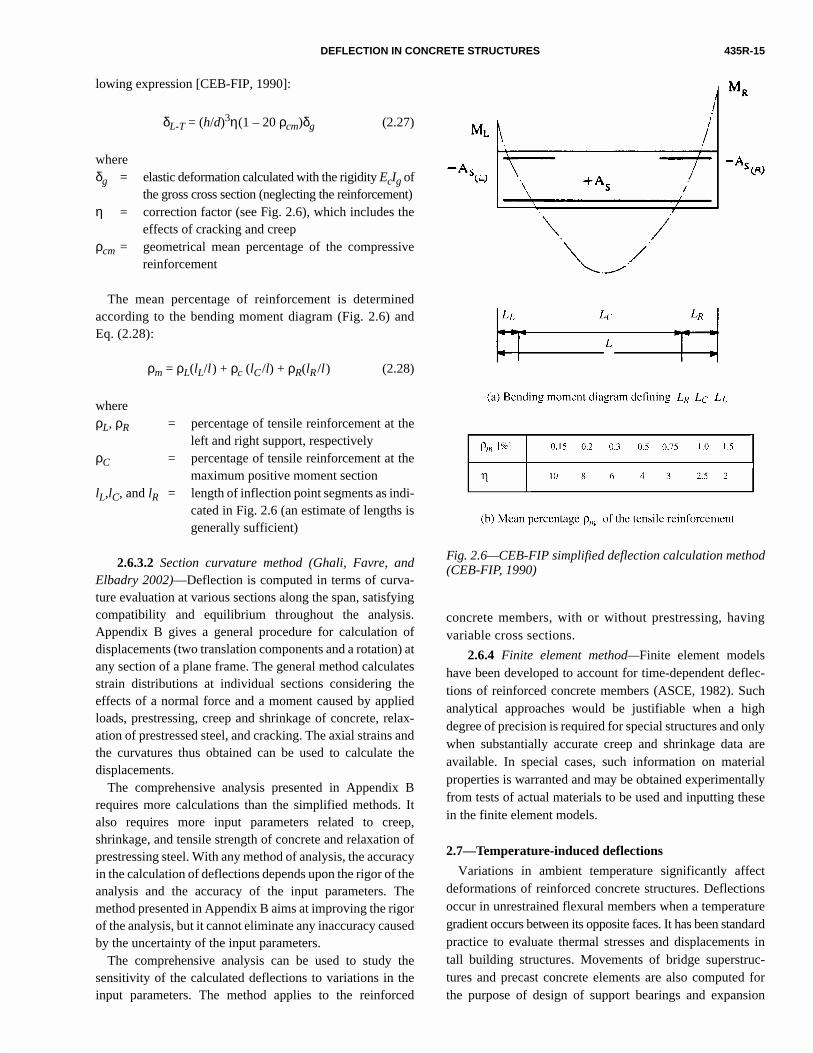
lowing expression [CEB-FIP, 1990]:
δL-T = (h/d)3η(1 – 20 ρcm)δg (2.27)
whereδg = elastic deformation calculated with the rigidity EcIg of
the gross cross section (neglecting the reinforcement)η = correction factor (see Fig. 2.6), which includes the
effects of cracking and creepρcm = geometrical mean percentage of the compressive
reinforcement
d
Fig. 2.6—CEB-FIP simplified deflection calculation metho(CEB-FIP, 1990)g
lsc-hh
lyreallye
cts
red
inc-rn
The mean percentage of reinforcement is determinedaccording to the bending moment diagram (Fig. 2.6) andEq. (2.28):
ρm = ρL(lL/l) + ρc (lC /l) + ρR(lR /l) (2.28)
whereρL, ρR = percentage of tensile reinforcement at the
left and right support, respectivelyρC = percentage of tensile reinforcement at the
maximum positive moment sectionlL,lC, and lR = length of inflection point segments as indi-
cated in Fig. 2.6 (an estimate of lengths isgenerally sufficient)
2.6.3.2 Section curvature method (Ghali, Favre, andElbadry 2002)—Deflection is computed in terms of curva-ture evaluation at various sections along the span, satisfyingcompatibility and equilibrium throughout the analysis.Appendix B gives a general procedure for calculation ofdisplacements (two translation components and a rotation) atany section of a plane frame. The general method calculatesstrain distributions at individual sections considering theeffects of a normal force and a moment caused by appliedloads, prestressing, creep and shrinkage of concrete, relax-ation of prestressed steel, and cracking. The axial strains andthe curvatures thus obtained can be used to calculate thedisplacements.
The comprehensive analysis presented in Appendix Brequires more calculations than the simplified methods. Italso requires more input parameters related to creep,shrinkage, and tensile strength of concrete and relaxation ofprestressing steel. With any method of analysis, the accuracyin the calculation of deflections depends upon the rigor of theanalysis and the accuracy of the input parameters. Themethod presented in Appendix B aims at improving the rigorof the analysis, but it cannot eliminate any inaccuracy causedby the uncertainty of the input parameters.
The comprehensive analysis can be used to study thesensitivity of the calculated deflections to variations in theinput parameters. The method applies to the reinforced
concrete members, with or without prestressing, havinvariable cross sections.
2.6.4 Finite element method—Finite element modehave been developed to account for time-dependent defletions of reinforced concrete members (ASCE, 1982). Sucanalytical approaches would be justifiable when a higdegree of precision is required for special structures and onwhen substantially accurate creep and shrinkage data aavailable. In special cases, such information on materiproperties is warranted and may be obtained experimentalfrom tests of actual materials to be used and inputting thesin the finite element models.
2.7—Temperature-induced deflections
Variations in ambient temperature significantly affedeformations of reinforced concrete structures. Deflectionoccur in unrestrained flexural members when a temperatugradient occurs between its opposite faces. It has been standarpractice to evaluate thermal stresses and displacements tall building structures. Movements of bridge superstrutures and precast concrete elements are also computed fothe purpose of design of support bearings and expansio

435R-16 ACI COMMITTEE REPORT
joint designs. Before performing an analysis for temperatureeffects, it is necessary to select design temperature gradients.Martin (1971) summarizes design temperatures that areprovided in various national and foreign codes.
An ACI 435 report on temperature-induced deflections(1985) outlines procedures for estimating changes in stiffnessand temperature-induced deflections for reinforced concretemembers. The following expressions are taken from thatreport.
2.7.1 Temperature gradient on unrestrained crosssection—With temperature distribution t(y) on the crosssection, thermal strain at a distance y from the bottom of thesection can be expressed by
∈ t(y) = αt(y) (2.33)
To restrain the movement due to temperature t(y), a stressis applied in the opposite direction to ∈ t(y):
f(y) = Ecαt(y) (2.34)
The net restraining axial force and moment are obtainedby integrating over the depth:
(2.35)
(2.36)
In order to obtain the total strains on the unrestrained crosssection, P and M are applied in the opposite direction to therestraining force and moment. Assuming plane sectionsremain plane, axial strain ∈ a and curvature φ are given by:
∈ a = (2.37)
(2.38)
The net stress distribution on the cross section is given by:
(2.39)
For a linear temperature gradient varying from 0 to ∆t, thecurvature is given by:
P f AdA∫ αEct y( )b y( )[ ] yd
0
h
∫= =
M f y n–( ) AdA∫ αEct y( )b y( ) y n–( )[ ]
0
h
∫ dy= =
PAEc
--------- αA--- t y( )b y( )[ ] yd
0
h
∫=
φ MEcI-------- α
I--- t y( )b y( ) y n–( )[ ] yd
0
h
∫= =
fn y( ) PA--- M y n–( )
I--------------------- Ecα t y( )–±=
(2.40)
In the case of a uniform vertical temperature gradient
constant along the length of a member, deflections for
simply supported (δss) and cantilever beams (δcont) are
calculated as:
(2.41)
(2.42)
The deflection-to-span ratio is given by:
(2.43)
where k = 8 for simply supported beams and 2 for cantilever
beams.
2.7.2 Effect of restraint on thermal movement—If a
member is restrained from deforming under the action of
temperature changes, internal stresses are developed.
Cracking that occurs when tensile stresses exceed the
concrete tensile strength reduces the flexural stiffness of the
member and results in increased deflections under subse-
quent loading. Consequently, significant temperature effects
should be taken into account in determining member stiff-
ness for deflection calculation. The calculation of the effec-
tive moment of inertia should be based on maximum
moment conditions.
In cases where stresses are developed in the member due
to restrain of axial deformations, the induced stress due to
axial restraint has to be included in the calculation of the
cracking moment in a manner analogous to that for including
the prestressing force in prestressed concrete beams.
APPENDIX A2
Example A2.1: Deflection of a four-span beam
A reinforced concrete beam supporting a 4-in. (100
mm) slab is continuous over four equal spans 1 = 36 ft
(10.97 m) as shown in Fig. A2.1 (Nawy, 1990). It is
subjected to a uniformly distributed load w = 700 lb/ft
φ α∆ th
---------=
δssφl
2
8------- α∆ t
h--------- l2
8---= =
δcontφl2
2------- α∆ t
h--------- l
2
h---= =
δl-- α∆ t
k--------- l
h---=
D
(10.22 kN/m), including its self-weight and a service load
wL = 1200 lb/ft (17.52 kN/m). The beam has the dimen-
sions b = 14 in. (355.6 mm), d = 18.25 in. (463.6 mm) at
midspan, and a total thickness h = 21.0 in. (533.4 mm).
The first interior span is reinforced with four No. 9 bars

435R-17
D = 700 Ib/ft
l<-36 tMb-36 ftA36 ft-+----36 ft-+jA t3 C D E
(a)
d’ = 3f in.
f’4 in, (10.4 mm) - - -
C-14 in.-I
k)
I4 in.
- -
t.
.c-1-JI-
ll
-2
Fig. A2.1-Details of continuous beam in Ex. A2.1 (Nawy, 1990, courtesy Prentiss Hall)
at midspan (28.6 mm diameter) at the bottom fibers andsix No. 9 bars at the top fibers of the support section.
Calculate the maximum deflection of the continuousbeam using the ACI 318 method.
Given:f,’ = 4000 psi (27.8 MPa), normal weight concrete
= 60,000 psi (413.7 MPa)percent of the live load is sustained 36 monthson the structure.
Solution-ACI MethodNote: All calculations are rounded to three significantfigures.Material properties and bending moment values
(24%00 MPa)‘ = 57,000 = +y = 57,000 @@i= 3.6 x lo6 psi
k = 29 x lo6 psi (200,000 MPa)
29x1@ = g 1modular ratio n = Es/EC = p .3.6~10~
modulus of rupture f, = 7.5 g = 7.5 e = 474 psi
(3.3 MPa)
For the first interior span, the positive moment =0.0772 wl*
+ MD = 0.0772 x 700(36.O)*‘x 12 = 840,000 in.-lb
+ ML = 0.0772 x 1200(36.0)p x 12 = 1,440,OOO in.-lb
+(!$-, + ML) = 0.0772x 1900(36,0)*x 12 = 2,280,OOOin.-lb
negative moment = 0.107 wf*- MD = 0.1071 x 700(36.0)* x 12 = 1,170,OOO in.-lb
-ML = 0.1071 x 1200(36.0)* x 12 = 2,000,OOO in.-lb
- (MD + ML) = 0.1071 x 1900(36.0)*x 12 = 3,170,000in.-lb
Effective moment of inertia IeFig. A2.2 shows the theoretical midspan and support

I 435R-18 ACI COMMITTEE REPORT
__-
b = 6, + 16h, = 78 in.
= gross areas for I# calculations
(a)
A:, = 6.0 in.221 in.
A: = 2.0 in.2
(b) ’
Fig. A2.2-Gross moment of inertia Ig cross sections in Ex. A2.1
cross sections to be used for calculating the grossmoment of inertia Ig.
1. Midspan section:Width of T-beam flange = b, + 16$ = 14.0 + 16 x 4.0= 78 in. (1981 mm)Depth from compression flange to the elastic centroid is:
y’ = VlYl + AY2N41 +A,)= 78(4x2)+ 14x(21-4)x12.5 = 654m
. .78x4 + 14 x 17
yI = h -y’ = 21.0 - 6.54 = 14.5 in.
Ig = T + 78 x 4(6.54 - 4f2j2
14C::_4)3 + 14(21-4) 2
+
= 21.000 in4
Depth of neutral axis:
= 690,000 in.-lb
(AS = four No. 9 bars = 4.0 in2).To locate the position, c, of the neutral axis, takemoment of area of the transformed flanged section,namely
b,(c - hjJ2 - 2nA,(d - c) + bh#c - hf) = 0or14(c - 4.0)2 - 2 x 8.1 x 4.0(18.25 - c) + 78 x 4(2c - 4.0)
0Z?r c2 + 4.17~ - 157.0 = 0
to give c = 3.5 in. Hence the neutral axis is inside theflange and the flange section is analyzed as a rectangularsection.
For rectangular sections,
T + 8.1 x 4 x c - 8.1 x 4 x 18.25 = 0
Therefore, c = 3.5 in.
I0
= v + 0.8 x 4 (18.25 - 3.5)2 = 8160 in4
Ratio &,/Ma:
D ratio = 69o,ooo ~082840,000 *

~ 435R-19
D + 50 percent L ratio = 690,000= 0.44 840,000o + 0.5 x 1,440,000
D + L ratio = 690,000 = 0302,280,OOO *
Effective moment of inertia for midspan sections:
Z, for dead load = 0.55 x 21,000 + 0.45 x 8160= 15,200 k4
Z, for + 0.5L = 0.086 x 21,000 + 0.914 x 8160= 9276 in.4
Z, for D + L = 0.027 x 21,000 + 0.973 x 8160= 8500 in.4
If using the simplified approach to obtain Z, (Section2.5.2.3) values of 14,200 in4(7 percent smaller), 9200 in4(1 percent smaller), and 8020 in4 (6 percent smaller), areobtained respectively.
2. Support section:
Ig 12 12
= 10,800 k4
Y, = 21 = 10.5 in.2
M,, = frZJyl = 470 ;o’$*m = 483,000 in.-lb
Depth of neutral axis:
2, = six No. 9 bars = 6.0 in.’ (3870 nun’&
dS= two No. 9 bars = 2.0 in.’ (1290 mm )= 21.0 - 3.75 = 17.30 in. (438 mm)
Similar calculation for the neutral axis depth c gives avalue c = 7.58 in.Hence,
bc3z,, = 3 + nA,(d - c)Z + (n - l)A,‘(c - d’)2
Ratio MJMO:
D ratio = 0.411,170,ooo
D + 50 percent L ratio =483,000 = 0.22
1,170,000 + 0.5 x 2,000,000D + L ratio = 483,000
3,170,000Effective moment of inertia for support section:
Z, for dead load = 0.07 x 10,800 + 0.93 x 6900= 7170 in.4
Z, for D + 0.5L = 0.01 x 10,800 + 0.99 x 6900= 6940 in.4
Z, for D + L = 0.003 x 10,800 + 0.99 x 6900= 6910 in.4
Average effective Ie for continuous spanaverage Z, = 0.85 I,,, + 0.15 Z,dead load: Z, = 0.85 x 15,200 + 0.15 x 7170
= 14,000 in.4
D + 0.5L: Z, = 0.85 x 9260= 8900 in.4
D + L: I e = 0.85 x 8500 +
Short-term deflection
+ 0.15 x 6940
0.15 x 6910 = 8260 in.4
The maximum deflection for Ithe first interior span is:
1 assumed = 1, for all practical purposes
o S = 0.0065(36 x 12)4x WAX 1 = 5.240 w _ in.
36 x lo6 1. 12 Z,
Initial dead-load deflection:
8 D = ‘.yz) = 0.26 in., say 0.3 in.
Initial live-load deflection:
8L=sL+D sD.6
L
= 5.240(1900) 4 5.240(700)8260 14,000
= 1.21 - 0.26 = 0.95 in., say 1 in.
Initial 50 percent sustained live-load deflection:
A*’p’ = bd = 0 (at midspan in this case)
multiplier A. = f/(1 + 5Op’)iFrom Fig. 2.5
T = 1.75 for 36-month sustained loadT = 2.0 for 5-year loading
Therefore,Am = 2.0 and A1 = 1.75
The total long-term deflection is
Deflection requirements (Table 2.5)
36 x 12 = 2.4 in. = 1.0 O.K180 180
>~SL in.,
l = 1.2 in. >360
6, = 1.0 ., O.K.
1- = 0.9 in. < sLT = 2.4 in., N.G.480
1- = 1.8 in. < S,, = 2.4 in., N.G.240
Hence, the continuous beam is limited to floors orroofs not supporting or attached to nonstructural ele-ments such as partitions.
Application of CEB-FIP method to obtain long-termdeflection due to sustained loads:

435R-20 ACI COMMITTEE REPORT
+A
midspan Q = --z = 4 x 1.0bd 78 x 18.25= 0.0028 =pc
-Asupport p = 2 = 6 x 1.0
W
($ b;
14 x18.25= 0.0235 = QL = pR
Assuming that the location of the inflection points asdefined by Ir, and ZR for negative moment region, and Zcfor the positive moment region in Figure 2.16 are as fol-lows:
L//L = L,/L = 0.21 and L&L = (l-0.21 x 2) = 0.58Also, assume pL = pRHence,
l om = 2(0.0235 x 0.2) + 0.0028 x 0.58= 0.0094 + 0.0017 = 0.0111 = 1.11 percent
From Fig. 2.6, 7 = 2.4From ACI Method Solution: Ig = 21,000 in.4Short-term deflection,
6 = o.oo69wz4 = 5240 wEcZ” l <
+ 5.240(700 + 1200)21,000
= 0.47 in., say 0.5 in.
Long-Term increase in deflection due to sustained load:
6 h3L-T = 2
0Ml - 2op,>a
= 1.52 x 2.4(1 - 20 x 0.0111)0.5= 1.35 in., say 1.4 in. (35 mm).
(1.41 in. by the ACI procedure solution)
Example A2.2: Temperature-induced deflections
These design examples illustrate the calculation pro-cedures for temperature induced deflections.
Example (a): Simply supported vertical wall panel -Linear temperature gradient
^ _ t = 40 F (4.4 C)o ( = 0.0000055 in./iIl./Fh = 4 in. (101 mm)
a) Single story span: L = 12 ft. (3.66 m)8 = (0.0000055 x 40 x 1442)/(4 x 8)
= 0.14 in. (3.6 mm), say 0.2 in.b) Two story span: L = 24 ft. (7.32 m)
s = (0.0000055 x 40 x 2sS2)/(4 x 8)= 0.57 in. (14.5 mm), say 0.6 in.
Example (b): Simply supported tee section - LinearTemperature gradient over depth
^ _ t = 40 F (4.4 C)o ( = 0.0000055 in./in./F h = 36 in. (914 mm)L = 60 ft. (18.4 m) - simply supportedS = (0.0000055 x 40 x 7202)/(36x 8)
= 0.40 in. (10 mm), say 0.5 in.Example (c): Simply supported tee section - Constanttemperature over flange depth
I =n =
^ _t =o ( =
h =L =
+=
69319 in4 (2.88 x 10” mm4)26.86 in (682 mm)40 F (4.4 C)0.0000055 in./in.p?36 in. (914 mm)60 ft. (18.4 m)
36
s =
(a/O po x 96) OI - 2~JwtY
(88,O;; x 0.0000055)/693190.00000698(+L2)/8 = (0.00000698 x 7202)/80.45 in. (11.4 mm), say 0.5 in.
CHAPTER 3-DEFLECTION OF PRESTRESSEDCONCRETE ONE-WAY FLEXURAL MEMBERS*
3.1-NotationAc =AA
g =s -
AP =
bbw =c =
cgc =cgs =C =
area of sectiongross area of concrete sectionarea of nonprestressed reinforcementarea of prestressed reinforcement in tensionzonewidth of compression face of memberweb widthdepth of compression zone in a fully-crackedsection
c, =c, =Ct =Cu =
d =
center of gravity of concrete sectioncenter of gravity of reinforcementcreep coefficient, defined as creep strain dividedby initial strain due to constant sustained stressPCI multiplier for partially prestressed sectionPCI multiplier for partially prestressed sectioncreep coefficient at a specific ageultimate creep coefficient for concrete at loadingequal to time of release of prestressingdistance from extreme compression fiber to cen-troid of prestressing steel
dp =
e, =
d' = distance from extreme compression fiber to cen-troid of compression reinforcementdistance from extreme compression fiber to cen-troid of prestressed reinforcementeccentricity of prestress force from centroid ofsection at center of span
e =cr
e, =
eccentricity of prestresscracked section
from centroid of
Ec =Eci =
eccentricity of prestress force from centroid ofsection at end of spanmodulus of elasticity of concretemodulus of elasticity of concrete at time of ini-tial prestress
Es = modulus of elasticity of nonprestressed rein-forcement
* Principal authors: A Aswad, D. R. Buettner and E. G. Nawy.

DEFLECTION IN CONCRETE STRUCTURES 435R-21
E =P
ES =
=2 =
f =cc
fp =
fp; =
fp/ =
f =P“
f, =
L ==gj-L
IL =‘If =I =cr
I, =
Ig =
I, =
&R =L =M, =Mcr =
ML =M, =MSD =n =
np =
P, =pi =
r =
REL =SH =t, =t =
modulus of elasticity of prestressed reinforce-mentstress loss due to elastic shortening of concretespecified compressive strength of concreteconcrete stress at extreme tensile fibers due tounfactored dead load when tensile stresses andcracking are caused by external loadstrength of concrete in tensioncalculated stress due to live loadstress in extreme tension fibers due to effectiveprestress, if any, plus maximum unfactoredload, using uncracked section propertiescompressive stress in concrete due to effectiveprestress only after losses when tensile stressis caused by applied external loadeffective prestress in prestressing reinforce-ment after lossesstress in prestressing reinforcement immediate-ly prior to releasestress in pretensioning reinforcement at jacking(5-10 percent higher than _$Jspecified tensile strength of prestressing ten-donsyield strength of the prestressing reinforcement
modulus of rupture of concrete 7.5flfinal calculated total stress in memberspecified yield strength of nonprestressed rein-forcementoverall thickness of memberdepth of flangemoment of inertia of cracked section trans-formed to concreteeffective moment of inertia for computation ofdeflectionmoment of inertia of gross concrete sectionabout centroid axismoment of inertia of transformed sectioncoefficient for creep loss in Eq. 3.7span length of beammaximum service unfactored live load momentmoment due to that portion of applied liveload that causes crackingmoment due to service live loadnominal flexural strengthmoment due to superimposed dead loadmodular ratio of normal reinforcement(= Es/Ec)modular ratio of prestressing reinforcement(= ~,K)effective prestressing force after lossesinitial prestressing force prior to transfer
radius of gyration = mstress loss due to relaxation of tendonsstress loss due to shrinkage of concreteinitial time intervaltime at any load level or after creep or shrink-age are considered
Yg =
Yt =
a =
6 =E, =
E =cr
Ep =
ESH =
Y =
distance from extreme compression fibers tocentroid of Ag
distance from centroid axis of gross section,neglecting reinforcement to extreme tensionfiberslength parameter that is a function of tendonprofile useddeflection or cambermaximum usable strain in the extreme com-pression fiber of a concrete element (0.003in. / in . )strain at first cracking loadstrain in prestressed reinforcement at ultimateflexureunit shrinkage strain in concreteshrinkage strain at any time raverage value of ultimate shrinkage strainultimate straincurvature (slope of strain diagram)curvature at midspancurvature at supportcorrection factor for shrinkage strain in non-standard conditions (5ee also Sec. 2.3.4)stress loss due to creep in concretestress loss due to concrete shrinkagestress loss due to relaxation of tendons
3.2-General3.2.1 Introduction-Serviceability behavior of pre-
stressed concrete elements, particularly with regard todeflection and camber, is a more important design con-sideration than in the past. This is due to the applicationof factored load design procedures and the use of high-strength materials which result in slender members thatmay experience excessive deflections unless carefullydesigned. Slender beams and slabs carrying higher loadscrack at earlier stages of loading, resulting in furtherreduction of stiffness and increased short-term and long-term deflections.
3.2.2 Objectives-This chapter discusses the factorsaffecting short-term and long-term deflection behavior ofprestressed concrete members and presents methods forcalculating these deflections.
In the design of prestressed concrete structures, thedeflections under short-term or long-term service loadsmay often be the governing criteria in the determinationof the required member sizes and amounts of prestress.The variety of possible conditions that can arise are toonumerous to be covered by a single set of fixed rules forcalculating deflections. However an understanding of thebasic factors contributing to fhese deformations willenable a competent designer to make a reasonable esti-mate of deflection in most of the cases encountered inprestressed concrete design. The reader should note thatthe word estimate should be taken literally in that theproperties of concrete which affect deflections (particu-larly long term deflections) are variable and not deter-minable with precision. Some of these properties have
435R-22 ACI COMMITTEE REPORT
values to which a variability of k 20 percent or more inthe deflection values must be considered. Deflectioncalculations cannot then be expected to be calculatedwith great precision.
3.2.3 Scope-Both short-term and long-term transversedeflections of beams and slabs involving prestressing withhigh-strength steel reinforcement are considered. Specificvalues of material properties given in this chapter, suchas modulus of elasticity, creep coefficients, and shrinkagecoefficients, generally refer to normal weight concrete al-though the same calculation procedures apply to light-weight concrete as well. This chapter is intended to beself-contained.
Finally several of the methods described in this chap-ter rely solely on computer use for analysis. They do notlend themselves to any form of hand calculation or ap-proximate solutions. The reader should not be deludedinto concluding that such computer generated solutionsfrom complex mathematical models incorporating use ofconcrete properties, member stiffness, extent of crackingand effective level of prestress somehow generate resultswith significantly greater accuracy than some of the othermethods presented. This is because of the range of varia-bility in these parameters and the difficulty in predictingtheir precise values at the various loading stages and loadhistory. Hence, experience in evaluating variability ofdeflections leads to the conclusion that satisfying basicrequirments of detailed computer solutions using variousvalues of assumed data can give upper and lower boundsthat are not necessarily more rational than present codeprocedures.
3.3-Prestressing reinforcement3.3.1 Types of reinforcement-Because of the creep and
shrinkage which occurs in concrete, effective prestressingcan be achieved only by using high-strength steels withstrength in the range of 150,000 to 270,000 psi (1862MPa) or more. Reinforcement used for prestressed con-crete members is therefore in the form of stress-relievedor low-relaxation tendons and high-strength steel bars.Such high-strength reinforcement can be stressed to ade-quate prestress levels so that even after creep andshrinkage of the concrete has occurred, the prestressreinforcement retains adequate remaining stress to pro-vide the required prestressing force. The magnitude ofnormal prestress losses can be expected to be in therange of 25,000 to 50,000 psi (172 MPa to 345 MPa).
Wires or strands that are not stress-relieved, such asstraightened wires or oil-tempered wires, are often usedin countries outside North America.
3.3.1.1 Stress-relieved wires and strands-Stress-relieved strands are cold-drawn single wires conformingto ASTM A 421 and stress-relieved tendons conform toASTM A 416. The tendons are made from seven wires bytwisting six of them on a pitch of 12 to 16 wire diametersaround a slightly larger, straight control wire. Stress-relieving is done after the wires are twisted into thestrand. Fig. 3.1 gives a typical stress-strain diagram for
wire and tendon prestressing stegl reinforcement,3.3.1.2 High-tensile-strength prestressing bars-High-
tensile-strength alloy steel bars for prestressing are eithersmooth or deformed to satisfy A S T M A 722 require-ments and are available in nominal diameters from J/e in.(16 mm) to 13/8 in. (35 mm). Cold drawn in order to raisetheir yield strength, these b a r s are stress relieved toincrease their ductility. Stress relieving is achieved byheating the bar to an appropriate temperature, generallybelow 500 C. Though essentially the same stress-relievingprocess is employed for bars a s for strands, the tensilestrength of prestressing bars has to be a minimum of150,000 psi (1034 MPa), with a minimum yield strengthof 85 percent of the ultimate strength for smooth barsand 80 percent for deformed bars
3.3.2 Modulus of elasticity-In computing short-termdeflections, the cross-sectional area of the reinforcingtendons in a beam is usually small enough that thedeflections may be based on the gross area of the con-crete. In this case, accurate determination of the modulusof elasticity of the prestressing reinforcement is notneeded. However, in considering time-dependent deflec-tions resulting from shrinkage and creep at the level ofthe prestressing steel, it is important to have a reasonablygood estimate of the modulus of elasticity of the pre-stressing reinforcement.
In calculating deflections under working loads, it issufficient to use the modulus o f elasticity of the pre-stressing reinforcement rather than to be concerned withthe characteristics of the entire stress-strain curve sincethe reinforcement is seldom stressed into the inelasticrange. In most calculations, the assumption of the modu-lus value as 28.5 x lo6 psi (PCI Design Handbook, FourthEdition) can be of sufficient accuracy considering the factthat the properties of the concrete which are more criti-cal in the calculation of deflections are not known withgreat precision. The ACI Code tates that the modulusof elasticity shall be established by the manufacturer ofthe tendon, as it could be less than 28.5 x lo6 psi.
When the tendon is embedded in concrete, the free-dom to twist (unwind) is lessened considerably and itthus is unnecessary to differentiate between the modulusof elasticity of the tendon and that of single-wire rein-forcement (AC1 Committee 435, 1979).
3.3.3 Steel relaxation-Stress relaxation in prestressingsteel is the loss of prestress that occurs when the wires orstrands are subjected to essentially constant strain over aperiod of time. Fig. 3.2 relates stress relaxation to time
t in hours for both stress-relieved and low-relaxation ten-dons.The magnitude of the decrease in the prestress de-pends not only on the duration of the sustained pre-stressing force, but also on the ratio fpilfw of the initialprestress to the yield strength of the remforcement. Sucha loss in stress is termed intrinsic stress relaxation.
If fpR is the remaining prestressing stress in the steeltendon after relaxation, the following expression defines
fPR for stress-relieved steel:

DEFLECTION IN CONCRETE STRUCTURES 435R-23
t Grade 270 strand
270
t250 -
00
;;._9 150
H&
100
’ Grade 160 alloy bar
Strand EP, = 27.5 X lo* psiWire Ep, = 29.0 X lo6 psi
Bar Ep, = 27.0 X lo6 psi (166.2 X lo3 MPa)
,l% Elongation
I I I I I I II -
0 0.01 0.02 0.03 0.04 0.05 0.06 0.07 in/in
Strain
Fig. 3.1-Typical stress-strain diagram for prestressing steel reinforcement
1
0.1 L I I ,I1111 I 1 f ,,llll I , 1 ,,,I11 I , 1 ,,I( [I I I I IllI&10 100 1,000 10,000 100,000 1,000,000
Time (hours)
Fig. 3.2-Relaxation loss versus time for stress-relieved low-relaxation strands at 70 percent of the ultimate (Post-TensioningInstitute Manual, fourth edition)

435R-24 ACI COMMITTEE REPORT
2 = 1 - (S)k - CL,,] (3.1)
In this expression, logt in hours is to the base 10, andthe ratio fpilfw must not be less than 0.55. Also, for low-relaxation steel, the denominator of the log term in theequation is divided by 45 instead of 10. A plot of Eq. 3.1is given in Fig. 3.3. In that case, the intrinsic stress-
10 100 1000Time, hours
10,000 100,000
Fig. 3.3-Stress relaxation relationship in stress-relievedstrands (Post Tensioning Manual, fourth edition)
relaxation loss becomes
(3.2)
where fpi is the initial stress in steel.If a step-by-step loss analysis is necessary, the loss
increment at any particular stage can be defined as
where tI is the time at the beginning of the interval andt2 is the time at the end of the interval from jacking tothe time when the loss is being considered. Therefore,the loss due to relaxation in stress-relieved wires andstrands can be evaluated from Eq. 3.3, provided thatf,i/f L 0.55, with fm = 0.85fP for stress-relieved strandsanBy0.90fPU for low-relaxation tendons.
It is possible to decrease stress relaxation loss by sub-jecting strands that are initially stressed to 70 percent oftheir ultimate strength fW to temperatures of 20 C to 100C for an extended time in order to produce a permanentelongation, a process called stabilization. The prestressingsteel thus produced is termed low-relaxation steel and hasa relaxation stress loss that is approximately 25 percentof that of normal stress-relieved steel.
Fig. 3.2 gives the relative relaxation loss for stress-
relieved and low-relaxation steels for seven-wire tendonsheld at constant length at 29.5 C. Fig. 3.4 shows stress
relaxation of stabilized strand at various tension andtemperature levels.It should be noted that relaxation losses may becritically affected by the manner in which a particularwire is manufactured. Thus, relaxation values change notonly from one type of steel to another but also frommanufacturer to manufacturer. Factors such as reductionin diameter of the wire and its heat treatment may besignificant in fixing the rate and amount of relaxation lossthat may be expected. Nevertheless, sufficient data existsto define the amount of relaxation loss to be expected inordinary types of prestressing wires or strands currentlyin use.
3.4-Loss of prestress3.4.1 Elastic shortening loss -A concrete element
shortens when a prestressing force is applied to it due tothe axial compression imposed. A s the tendons that arebonded to the adjacent concrete simultaneously shorten,they lose part of the prestressing force that they carry.
In pretensioned members, this, force results in uniformlongitudinal shortening. Dividing the reduction in beamlength by its initial length gives a strain that whenmultiplied by the tendon modulus of elasticity gives thestress loss value due to elastic shortening. In post-tensioned beams, elastic shortening varies from zero if alltendons are simultaneously jacked to half the value in thepretensioned case if several sequential jacking steps areapplied.
3.4.2 Loss of prestress due to creep of concrete-Thedeformation or strain resulting from creep losses is afunction of the magnitude of t applied load, its dur-ation, the properties of the co crete including its mixproportions, curing conditions, the size of the elementand its age at first loading, and the environmental con-ditions. Size and shape of the element also affect creepand subsequent loss of prestress. Since the creepstrain/stress relationship is essentially linear, it is feasibleto relate the creep strain ECR to the elastic strain cEL
such that the ultimate creep coefficient C, can bedefined as
c, = 3El4 (3.4)
The creep coefficient at any time t in days can betaken as
c, = $yJ@C”(See Eq. 2.7 of Chapter 2; also Branson, et. al, 1971,1977 and ACI 209, 1971, 1992)
The value of C,, usually ranges between 2 and 4, withan average of 2.35 for ultimate creep. The loss of pre-

DEFLECTION IN CONCRETE STRUCTURES 435R-25
Temperature (*C)100 “C 60 “C 40 “C
11 - 7 -
18 - lo- 6 -16- g-
8- 5-14- 7 -12 - 6 - 4-
l0 - 5 - 3-4 -
*-- 3 - 2 -6 -4 - 2 -
l-l-
2-
20 ‘C Temp
6
1 day 10 days 1 0 0 day s 1 year 30 year s
Stress
1 2 3 4 5 61 10 10 10 10 10 10
Time in HoursFig. 3.4-Stress relaxation of stabilized strand at various tensions and temperatures (courtesy STELCO Inc., Canada)
c
taiged
wcptataiosAth
stress for bonded prestressed members due to creep canbe defined as
AfpCR = C (3.6)
where fcs is the stress in the concrete at the level of thecentroid of the prestressing tendon. In general, this lossis a function of the stress in the concrete at the sectionbeing analyzed. In post-tensioned, nonbonded drapedtendon members, the loss can be considered essentiallyuniform along the whole span. Hence, an average valueof the concrete stress between the anchorage points canbe used for calculating the creep in post-tensioned mem-bers. A modified ACI-ASCE expression for creep losscan be used as follows:
AfPCR (3.7)l
where
KCR = 2.0 for pretensioned members= 1.60 for post-tensioned members
(both for normal weight concrete)- f =cs stress in concrete at the cgs level of the re-
inforcement immediately after transfer
fcsd = stress in concrete at the cgs level of the re-inforcement due to all superimposed deadloads applied after prestressing is accom-plished
KCR should be reduced by 20 percent for lightweightoncrete.
Fig. 3.5 shows normalized creep strain plots versusime for different loading ages while Fig. 3.6 illustrates in
three-dimensional surface the influence of age at load-ng on instantaneous and creep deformations. Fig. 3.7 ives a schematic relationship of total strain with timexcluding shrinkage strain for a specimen loaded at a oneay age.3.4.3 Loss of prestress due to shrinkage of concrete-Asith concrete creep, the magnitude of the shrinkage ofoncrete is affected by several factors. They include mixroportions, type of aggregate, type of cement, curingime, time between the end of external curing and thepplication of prestressing, and the environmental condi-ions. Size and shape of the member also affect shrink-ge. Approximately 80 percent of shrinkage takes placen the first year of life of the structure. The average valuef ultimate shrinkage strain in both moist-cured andtream-cured concrete is given as 780 x lo4 in./in. in theCI 209R-92 Report. This average value is affected by
he duration of initial moist curing, ambient relativeumidity, volume-surface ratio, temperature; and con-
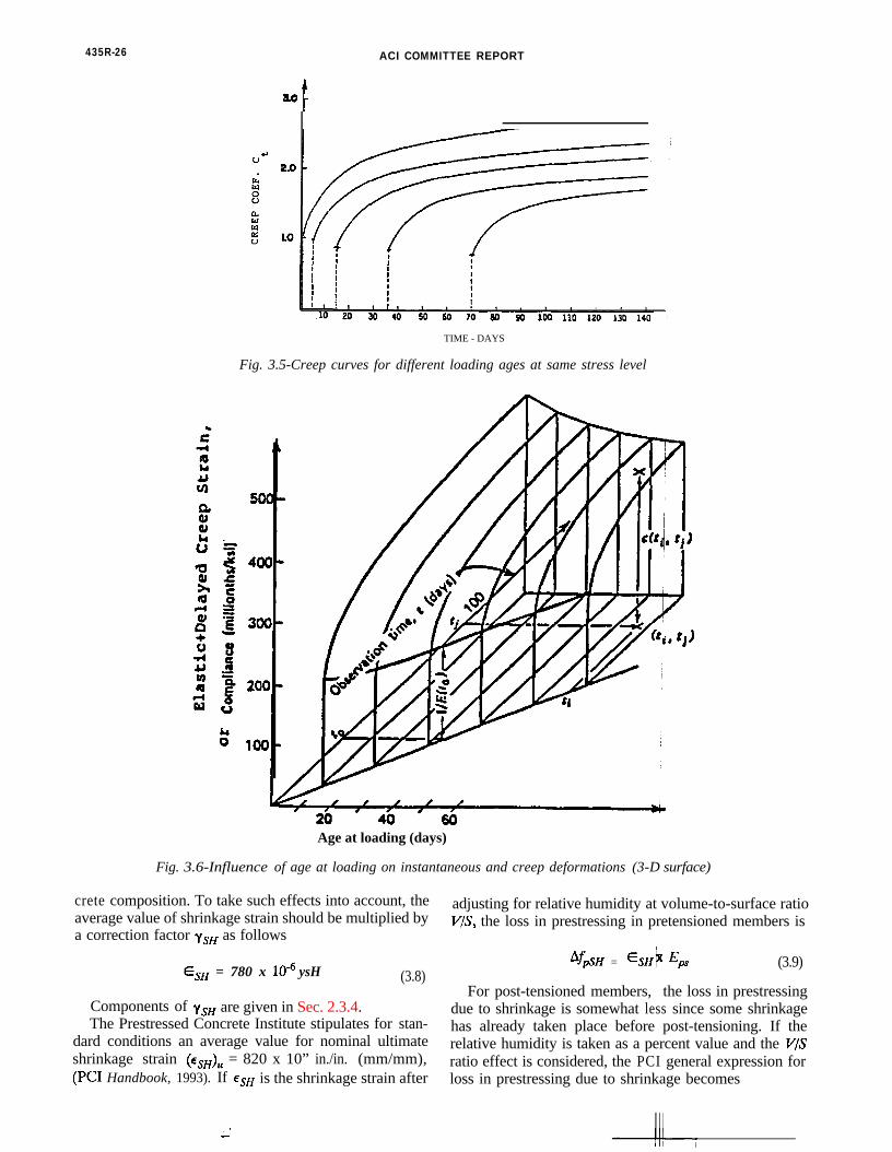
435R-26 ACI COMMITTEE REPORT
TIME - DAYS
Fig. 3.5-Creep curves for different loading ages at same stress level
Age at loading (days)
Fig. 3.6-Influence of age at loading on instantaneous and creep deformations (3-D surface)
crete composition. To take such effects into account, theaverage value of shrinkage strain should be multiplied bya correction factor ysH as follows
ESH = 780 x lo-6 ysH (3.8)
Components of ysH are given in Sec. 2.3.4.The Prestressed Concrete Institute stipulates for stan-
dard conditions an average value for nominal ultimateshrinkage strain (es&, = 820 x 10” in./in. (mm/mm),(PC1 Handbook, 1993). If eSH is the shrinkage strain after
adjusting for relative humidity at volume-to-surface ratioV/S, the loss in prestressing in pretensioned members is
‘fpSH = %H t Eps (3.9)
For post-tensioned members, the loss in prestressingdue to shrinkage is somewhat less since some shrinkagehas already taken place before post-tensioning. If therelative humidity is taken as a percent value and the V / Sratio effect is considered, the PCI general expression forloss in prestressing due to shrinkage becomes

435R-27
Fig. 3.7-Typical concrete strain versus time curve for constant stress applied at release time
Af@* = 8.2 x 10⁻⁶K&dl -0.06- V S )(100 - RH) (3.10)
where KsH = 1.0 for pretensioned members. Table 3.1
Table 3.1---Values of KsH for post-tensioned members
Time from end of moist curing toapplication of prestress, days
&H
Source: Prestressed Concrete Institute
1 3 5 7 10 20 30 60
0.92 0.85 0.80 0.7 0.73 0.64 0.58 0.45
gives the values of KsH for post-tensioned members.Adjustment of shrinkage losses for standard conditions
as a function of time t in days after seven days for moistcuring and three days for steam curing can be obtainedfrom the following expressions (Branson, et.al, 1971):
a) Moist curing, after seven days:
(3.11a)
where (Q&,, is the ultimate shrinkage strain, t = time indays after shrinkage is considered.
b) Steam curing, after one to three days:
(3.11b)
Fig. 3.8 schematically shows shrinkage strain versustime.
It should be noted that separating creep from shrink-age calculations as presented in this chapter is an ac-
-cepted engineering practice. Also, significant variationsoccur in the creep and shrinkage values due to variationsin the properties of the constituent materials from thevarious sources, even if the products are plant-producedsuch as pretensioned beams. Hence, it is recommendedthat information from actual tests be obtained especiallyon manufactured products, large span-to-depth ratiocases and/or if loading is unusually heavy (Aswad, 1985,1989, 1992).
3.4.4 Friction losses in post-tensioned beams-Relax-ation losses are covered in 3.3.3. Loss of prestressingoccurs in post-tensioned members due to friction be-tween the tendons and the surrounding concrete ducts.The magnitude of this loss is a function of the tendonform or alignment, called the curvature effect, and thelocal deviations in the alignment, called the wobble ef-fect. The values of the loss coefficients are affected bythe types of tendons and the duct alignment. Whereasthe curvature effect is predetermined, the wobble effectis the result of accidental or unavoidable misalignment,since ducts or sheaths cannot be perfectly held in place.Section 186.2 of ACI 318-89 and Table R18.6.2 of theCommentary to the code give the friction coefficientsthat apply to the friction loss in the various types ofprestressing wires and tendons.

3C
drfs
wtatctS3c
cap
iepl
dt
Ultimate E,,-6
780 to 820 x 10 in / in-----------
1 l 28
l 365
Fig. 3.8-Shrinkage strain versus time curve
/Time t (days)
catltc
i
a
f
t
it
ff
sroacta
.5-General approach to deformation considerations -urvature and deflectionsIn beam-like structures the curvature at any section,
efined as + = l/R, is the key element in calculatingotations and deflections. Based on geometry of the de-lected shape, the two following expressions are derived,ee Fig. 3.9.
(3.12a)
A
6 BA = qmi!xI
(3.12b)
here 4 is the curvature, 8 is the rotation and S is theangential deviation (deflection). These two expressionsre generalizations of the familiar Mohr or moment-areasheorems, and are applicable whether sections areracked or uncracked. When the material is linearly elas-ic, 4 can be replaced by M/EI. Software programs useimpson’s rule to approximate the above integrals. Fig..9(c) shows how the deflection y at any section can bealculated.
Based on these fundamental principles, the designeran calculate the curvature and rotation incrementally atny section and hence the deflection or camber of therestressed beam at the critical sections.
Short-term deflections are defined as those occurringnstantaneously under the application of any internal orxternal force. The time element is assumed to be unim-ortant, no matter what the rate of loading, provided theoad is applied within a matter of hours.
In general, the principal variables affecting short-term eflections of a prestressed concrete beam are the magni- ude and distribution of the load, the magnitude and ec-
entricity of the prestress, the length of the span, the sizend configuration of the cross section, boundary condi-ions and the properties of the concrete. More specifical-y, the effect of critical variables may be summarized byhe magnitude of the strain or stress gradient or theurvature at a section and its variation along the span.
The initial curvature at a particular section (Fig. 3.10)s defined by
4 = ‘bi - %i = bfi h EC1
(3.13)
nd A4 = Pe (3.15)
or use in Eq. 3.13 and where P is the prestressing force.The stress and strain distributions in Fig. 3.11 depict
he conditions existing after a given time. The normal
n which tensile strains are considered positive, and M ishe moment at the section.
In most cases, the amount of prestressing steel rein-orcement has a negligible effect on section propertiesor short-term deflections due to gravity loads.
3.5.1 Beams subjected to prestressing only-Stress andtrain distributions over the depth of a cross section of aectangular bonded beam immediately after applicationf the prestressing force are shown in Fig. 3.10. It isssumed that there is a linear relationship between con-rete stress and strain. Under normal conditions both ofhese assumptions are reasonably correct. The stress atny level is given by the well-known relationships:
fP= - - MYA 7
(3.14)

DEFLECTION IN CONCRETE STRUCTURES 435R-29
(a) General Beam DeformationCurvature $ =I/R
(b) Beam Strain at Any Section(Curavture 4 =( Eb’ ‘E,)/h )
(c) Beam Elastic Curve Deflection y and Tangential Deviation s,, 6 Bc,
Fig. 3.9-Beam elastic curve deformation
h dn I 1 .
$1
&liiisl
(a)
C’ 4 l--a--JSTRESS STRAIN
(b) (c)
Fig. 3.10-Stress and strain distribution immediately after application of prestress

435R-30 ACI COMMITTEE REPORT
(a)
H -
p-bt_l IEbt,._1STRESS STRAIN
w w
Fig. 3.11-Stress and strain distribution at a time t after initial application of prestress
stresses on the section decrease as a result of a reductionin the prestressing force while there is a general shift tothe right in the strain distribution accompanied by an in-crease in the strain gradient.
These changes are caused by an interaction betweencreep and shrinkage of the concrete and relaxation of thereinforcement. All of these effects progress with time andcontinuously impact on each other. However, to simplifythe calculation, it is preferable to treat these three typesof strains separately.
Consider first the effect of shrinkage strains. It isassumed that each element of concrete in the cross-sec-tion shrinks equally. Thus, the shrinkage strain distribu-tion after a time t is given in Fig. 3.12b. The distributionof shrinkage strain causes a reduction in the reinforce-
(a)
Aft
h
%
H
STRAIN STRESS
(b) (c)
STRAIN
Fig. 3.12-Stress and strain due to shrinkage
ment strain which corresponds to a reduction in the pre-stress. The loss in prestress causes a change in the stressdistribution over the depth of the section as indicated inFig. 3.12c and the corresponding change in the strain dis-tribution, Fig. 3.12d. Thus, the change in curvature is
(3.16)h’
The effect of the relaxation losses in the steel rein-forcement is quite similar to that of shrinkage. At a timet there is a finite loss in the prestressing force whichcreates a change in the curvature as explained above. Theeffects of the creep of the concrete are not as simple,since the reduction in steel stress causes changes in the

DEFLECTION IN CONCRETE STRUCTURES 435R-31
rate of creep strain. It is assumed that the amount ofcreep strain at a given time is proportional to the stress.Thus, the change in strain caused by creep is directly pro-portional to the instantaneous strain distribution (Fig.3.10c), which is directly related to the stress distribution.This change in the strain distribution involves a contrac-tion at the level of the steel, hence, a reduction in pre-stress. The reduction in prestress caused by creep, shrink-age, and relaxation decreases the normal stress, which inturn reduces the rate of creep.
A qualitative curvature versus time curve is shown inFig. 3.13. As in the case of short-term deflections, the
Curvature
A
Time-Dependent Curvature
lnstanteneous Curvature
I Time
Fig. 3.13-Curvature versus time for a beam subjected to prestress only
magnitude of the deflection may be estimated by themagnitude of the stress gradient over the depth of thesection after release of prestress. If the stress gradient isvery small, then shrinkage and relaxation are bound todominate, in which case the beam may deflect downward.However, under usual circumstances the stress gradientis large and creep dominates the deflection thus causingthe beam to move upward causing increased camber ina simply supported case (ACI 435, 1979).
3.5.2 Beams subjected to prestressing and external loads
--If the beam considered in t h e preceding paragraph issubjected to gravity load, the stre s distribution across thesection at a given point along t e span may be as indi-cated in Fig. 3.14d. Provided neither the concrete nor the
(a)
STRESS STRESS
(b) (c)
STRESS
(d)Fig. 3.14-Stress distribution due to prestress and transverse loads
reinforcement is strained into the inelastic range, thestress distribution caused by the prestressing force (Fig.3.14b) can be superimposed on the stress distributioncaused by the transverse load on the uncracked trans-formed section (Fig. 3.14c) to obtain the total stressdistribution shown in Fig. 3.14d.
The strain distribution shown in Fig. 3.15b corresponds
to the stress distribution in Fig. 3.14c. It depicts thestrains that would occur in an uncracked section underthe influence of only the transverse load. The short-termcurvature is(3.17)
where the subscripts b and t define the bottom and topfibers respectively.
1

435R-32 ACI COMMITTEE REPORT
(a)
‘bi & bt
STRAlN
(b)
Fig. 3.15-Strain distribution due to transverse loading only
The changes in the curvature or in the deflection ofthe beam caused by the combined prestress and thetransverse load are henceforth determined by superposi-tion. Both of these curvature distributions will changewith time. The deflections corresponding to these twoimaginary systems are shown in Fig. 3.16.
Deflection
UP
t
A (Due To Prestress)
m
^ - + o S
6 (Due To Load)
Fig. 3.16-Deflection versus time due to prestress and transverse loads
To get the net deflection, the deflections caused by theprestress and transverse load can be added as indicatedby the (A-G) curve. It is seen that the magnitude of thebeam deflection (and whether it deflects upward ordownward) depends on the relative effect of the prestressand of the transverse loads. Ideally, a beam can bedesigned to have a small camber at midspan at the ser-
vice load level or at a fraction of the service load level.3.5.3 Moment-curvature relationship--The instantaneous
moment-curvature relationshipsection is illustrated in Fig. 3.1
r a prestressed cross. Concrete can sustain
tensile stresses and contribute t o the carrying capacity ofa member until cracking occurs at a moment MCP A mo-ment M, larger than the moment M,, producescurvature that can be defined a
(3.18)
where P is the prestressing force, and eC, is its eccentricity

435l?-33
CRACKING
M’ 0
d is eccentricity ofprestress consideringtension stiffening, "effective 0’
0 0. 0CI
CURVATURE
Fig. 3.17 Moment versus curvature relationship in prestressed section
relative to the centroid of the cracked section. The dropin rigidity due to cracking is represented by the horizon-tal line at the M,, level. For the prestressed section, bothIcr and ycr (and in turn e,,) are dependent on the loadinglevel, with the M-4 becoming nonlinear after cracking. Itis important to note that the shift in the centroid of thecross section upon cracking results in larger prestressingforce eccentricity, ecr than the uncracked member eccen-tricity. This fact is particularly significant in flangedmembers, such as double tees which are characterized bythe relatively low steel area ratio pf) and because con-crete tensile strength is not zero, cracking does notextend to the neutral axis. In addition, uncracked con-crete which exists between cracks in the tension zone,contributes to the stiffness of the member (tensionstiffening). Taking this into account, the M-4 diagrambecomes continuous, as indicated by line A in Fig. 3.17and as is usually accepted in engineering practice (ACI318, 1989) and verified by numerous tests (Aswad, 1992).
3.6-Short-term deflection and camber evaluation inprestressed beams
Several methods to estimate short-term and long-termdeflections of prestressed concrete structural membersare presented in this article. Included are procedures foruncracked members and cracked members.
3.6.1 Uncracked members-When a concrete section issubjected to a flexural stress which is lower than themodulus of rupture of concretef,, the section is assumedto be uncracked and thus its behavior is linear. Underthis condition, the deflection is calculated by the basicprinciples of mechanics of elastic structures. In pre-stressed concrete construction, the immediate deflection,
or camber, due to the effects of initial prestressing Pi andmember self-weight is generally in the elastic uncrackedrange. Therefore, the elastic formulas presented in Table3.2 could be used to calculate the instantaneous deflec-
tion of the members. The value of Pi is equal to thejacking force less the initial prestress loss due to an-chorage set, elastic shortening, and the relatively smallrelaxation loss occurring between jacking and releasetime. Since Pi varies from section to section a weightedaverage may be used. An average initial loss of 4-10 per-cent can be reasonably used in order to get fpi.Unless test results are available, the modulus of elas-ticity of concrete can be estimated from the expressionrecommended in ACI 318 (See Chapter 2, Section 2.3).For uncracked sections, it is customary to use the grossmoment of inertia Ig for pretensioned members and thenet moment of inertia Z, for post-tensioned memberswith unbonded tendons.
3.6.2 Cracked members - Effective Ie method--In pre-stressed concrete members, cracks can develop at severalsections along the span under maximum load. Thecracked moment of inertia I,, applies at cracked sectionswhile the gross moment of inertia applies in betweencracks. ACI 318 (Section 18.4.2c) requires that a bilinearmoment-deflection relationship be used to calculate in-stantaneous deflections when the magnitude of tensile
stress in service exceeds 6&‘. A value of 12 &’ is per-mitted when the immediate and long-term deflections arewithin the allowable limits. 1s is used for the portion ofmoment not producing such tensile stress, while for theremaining portion of moment, Icr is used.
The effective moment of inertia Ie for simply sup-

435R-34 ACI COMMITTEE REPORT
Table 3.2-Short-term deflection in prestressed concrete beams (subscript c indicates midspan, subscript e, support)
Load deflection Prestress camber
J-1
.
v
w
e&J - - - - - - I - - - - --
P ec P
1
W
b-
;‘~#
.-I--.-a*I
w b6 -
= 2 4 E I(31 2 - 4b2)
sPI2=-8N C
2ec + (e. - ec) 3 8
I2 1I2 a2'$q + M,-@J 6.
+ 9c9c- - - - - - - - - - - -
W c9sP-
1a- P
I--l
t-8 J?.
6 = SWI’ Pec12 12
384EI‘@ 512
c486f-V
8EI % 8

DEFLECTION IN CONCRETE STRUCTURES 435R-35
ported beams, cantilevers, and continuous beams betweeninflection points is given in ACI 318-89, Section 9.5.2.3,but with the modified definitions of M,, and A4, for pre-stressed concrete as follows:
or
where
(3.19a)
(3.19b)
(3.19c)
The value of fr in Eq. 3.19c is taken as 7.5 E.b =
=
Ig =
MC, =
M, =
Y, =
reduction factor for sand lightweight con-crete0.85 and 0.70 for all lightweight concrete
modulus of rupture = 7.5h&total calculated stress in membercalculated stress due to live loadmoment of inertia of the cracked section,from Eq. 3.21, Section 3.6.3gross moment of inertiamoment due to that portion of unfactoredlive load moment M, that causes crackingmax unfactored live load momentdistance from neutral axis to tensile face
The effective moment of inertia I, in Eq. 3.19a and bthus depends on the maximum moment M, due to liveload along the span in relation to the cracking momentcapacity M,, of the section due to that portion of the liveload that caused cracking.
In the case of beams with two continuous ends ACI318-89 allows using the midspam Z,. However, more ac-curate values can be obtained when the section isuncracked using the following expressions as discussed inChapter 2, Section 2.5.
Avg. I, = 0.70Im + a.i5(1,, + I&) (3.20a)
and for continuous beams with one end continuous,
Avg. Z, = 0.85Im + &lS(r,,,. Md) (3.20b)
where I, is the midspan section moment of inertia andI,. and Zc2 are the end-section
?”ments of inertia.
In this method, I, is first etermined and the de-flection is then calculated by substituting I, for Ig in theelastic deflection formulas.
3.6.3 Bilinear computation method-In graphical form,the load deflection relationship follows Stages I and II ofFig. 3.18. The idealized diagra reflecting the relation
Load b,
II Post-cracking i Post-serviceability I
Deflection A
Fig. 3.18-Load-deflection relationship in prestressed beam: Region precracking stage; Region postcracking stage; Region III, post-serviceability stage
”between moment and deflectiois shown in Fig. 3.19.
for the Is and I,, zones
ACI 318 requires that computation of deflection in thecracked zone in the bonded tendon beams be based onthe transformed section whenever the tensile stress f, inthe concrete exceeds the modulus of rupture fr, Hence,S,, is evaluated using the transformed I,, utilizing thecontribution of the reinforcement in the bilinear methodof deflection computation. The cracked moment of iner-tia can be calculated by the PCI approach for fully pre-stressed members by means of the
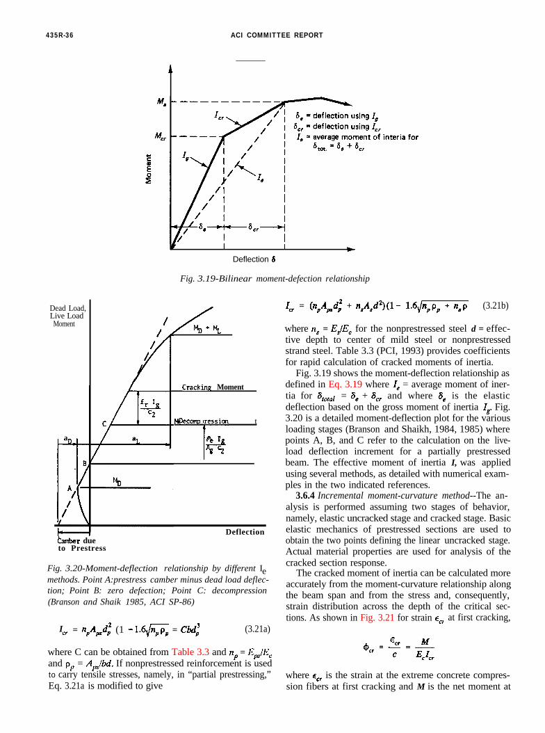
435R-36 ACI COMMITTEE REPORT
Deflection 6t
Fig. 3.19-Bilinear moment-defection relationship
Ict = npApdi (1 - 1.6/G = Cbd’ (3.21a)
where C can be obtained from Table 3.3 and np = EpF/Ecand p, = AJbd. If nonprestressed reinforcement is usedto carry tensile stresses, namely, in “partial prestressing,”Eq. 3.21a is modified to give
47 = @,A,dp’ + n,A,dz)(l - ‘.6,/m (3.21b)
where n, = EJEc for the nonprestressed steel d = effec-tive depth to center of mild steel or nonprestressedstrand steel. Table 3.3 (PCI, 1993) provides coefficientsfor rapid calculation of cracked moments of inertia.
Fig. 3.19 shows the moment-deflection relationship asdefined in Eq. 3.19 where I, = average moment of iner-tia for S,,,, = S, + 8, and where 8, is the elasticdeflection based on the gross moment of inertia Ig. Fig.3.20 is a detailed moment-deflection plot for the various
Dead Load,Live Load
Moment
a
Mafnen tDecomu ression
Pe I3Bpcr
Cracking Moment
DeflectionCamber dueto Prestress
Fig. 3.20-Moment-deflection relationship by different Iemethods. Point A:prestress camber minus dead load deflec-tion; Point B: zero defection; Point C: decompression(Branson and Shaik 1985, ACI SP-86)
loading stages (Branson and Shaikh, 1984, 1985) wherepoints A, B, and C refer to the calculation on the live-load deflection increment for a partially prestressedbeam. The effective moment of inertia I, was appliedusing several methods, as detailed with numerical exam-ples in the two indicated references.
3.6.4 Incremental moment-curvature method--The an-alysis is performed assuming two stages of behavior,namely, elastic uncracked stage and cracked stage. Basicelastic mechanics of prestressed sections are used toobtain the two points defining the linear uncracked stage.Actual material properties are used for analysis of thecracked section response.
The cracked moment of inertia can be calculated moreaccurately from the moment-curvature relationship alongthe beam span and from the stress and, consequently,strain distribution across the depth of the critical sec-tions. As shown in Fig. 3.21 for strain ec, at first cracking,
where E, is the strain at the extreme concrete compres-sion fibers at first cracking and M is the net moment at


435R-38 ACI COMMlTTEE REPORT
(a) (c) (d)
Fig. 3.21-Strain distribution and curvature at controlling loading stages (Nawy, 1989): a) initial prestress; b) effectiveprestress after losses; c) service load; d) failure. If section is cracked at service load, Fig. 3.21c changes to reflect tensilestrain at the bottom fibers (see Fig. A3.2)
the cracking load (see Eq. 3.18), including the pre-stressing primary moment M,, about the centroid (center-of-gravity of the concrete) of the section under consid-eration. Eq. 3.21 can be rewritten to give
where f is the concrete stress at the extreme compressivefibers on the section. The analysis is performed assumingtwo stages of behavior, namely, elastic uncracked stageand cracked stage. Basic elastic mechanics of prestressedsections are used to obtain the two points defining thelinear uncracked stage. Actual material properties areused for analysis of the cracked section response.
In summary, the distribution of strain across the depthof the section at the controlling stages of loading islinear, as is shown in Fig. 3.21, with the angle of curva-ture dependent on the top and bottom concrete extremefiber strains E,~ and Q, and whether they are in tensionor compression. From the strain distribution, the curva-ture at the various stages of loading can be expressed asfollows:
1) Initial prestress:
(3.22a)
2) Effective prestress after losses:
3) Service load:
(3.22b)
4 = E* h Ecb (3.22c)
4) Failure:
(3.226)
A plus sign for tensile strain and a minus sign forcompressive strain are used, so that the bottom fiberstrains in Fig. 3.21c can be in tension or compressionusing the appropriate sign (see Fig. A3.3 of Ex. A3.2).
Fig. 3.21 shows the general strain distribution andcurvature at the controlling loading stages defined in Eq.3.22, in this case an uncracked section at service load. Ifthe section is cracked, as in Ex. A3.2, Fig. 3.21c shouldreflect tensile strain at the bottom fibers using a plus signfor tensile strain and a minus for compressive strain. It isimportant to recognize that curvatures 4 at various loadlevels and at different locations along the span can bespecifically evaluated if the beam is divided into enoughsmall segments. Because of the higher speed personalcomputers today, a beam may be easily divided into 40 or100 sections. The trapezoidal rule would be accurateenough, with the only penalty being a few more milli-seconds in computer execution time.
3.7-Long-term deflection and camber evaluation in pre-stressed beams
If the external load is sustained on the prestressedmembers, the deflection increases with time, mainly be-cause of the effects of creep and shrinkage of concreteand relaxation of the prestressing reinforcement. In suchcases, the total deflection can be separated into twoparts: the instantaneous elastic part (previously discussed)and the additional long-term part that increases withtime.
Several methods are available for camber and deflec-tion calculation, some more empirical and others morerefined. This chapter presents in detail the simplified PCImultipliers method even though it is sometimes moreconservative, since it is the most commonly used for

DEFLECTION IN CONCRETE STRUCTURES 435R-39
deflection and camber calculation in normal size andspan prestressed beams such as double tees, hollow coreslabs and AASHTO type beams. Numerical examples onits use are given in the appendix.
It is worthwhile noting that prestressed building pro-ducts generally comply with the deflection limits in Table9.5(b) of ACI 318-89. Industry and local practices, how-ever, may be more stringent, such as requiring thatdouble tee or hollow core slabs should have a slightcamber under half of the design live load. It is also goodpractice to never allow a calculated bottom tension stressdue to sustained loads.
Other selected methods are briefly described and ref-erence made to existing literature for details on camberand deflection design examples in those references, thatthe designer can choose for refined solutions.
3.7.1 PCI multipliers method-The determination oflong-term camber and deflection in prestressed membersis more complex than for nonprestressed members due tothe following factors:
1. The long-term effect of the variation in pre-stressing force resulting from the prestress losses.
2. The increase in strength of the concrete after re-lease of prestress and because the camber and deflectionare required to be evaluated at time of erection. The PCIDesign Handbook, fourth edition, provides a procedurewherein the short term deflections (calculated using con-ventional procedures) are multiplied by factors (multi-pliers) for various stages of the deflection (erection,final), for deflections due to prestress dead and appliedloads and for composite and noncomposite sections toobtain long term deflections. These multipliers vary from1.80 to 3.00, as shown in Table 3.4 (PCI Design Hand-book, 4th ed., 1993).
Table 3.4-PCI multipliers C, for long-term camber and deflection
At erection:1) Deflection (downward) component-apply to the elastic deflection due
to the member weight at release of prestress
Without composite topping With composite topping
1.85 1.85
2) Camber (upward) component-apply to the elastic camber due to pre-stress at the time of release of prestress
1.80 1.80
Final:3) Deflection (downward) component-apply to the elastic deflection due
to the member weight at release of prestress
2.70 2.40
4) Camber (upward) component-apply to the elastic camber due to pre-stress at the time of release of prestress
2.45 2.20
5) Deflection (downward)--apply to the elastic deflection due to thesuperimposed dead load only
3.00 3.00
6) Deflection (downward)-apply to the elastic deflection caused by thecomposite topping
- 2.30
Where C, = multiplier; As = area of nonprestressed reinforcement and AP = area of prestressed strands.
Shaikh and Branson (1970) propose that substantialreduction can be achieved in long-term deflections by theaddition of nonprestressed mild steel reinforcement.
When such reinforcement is used, a reduced multiplierC, can be used as follows, to reduce the values in Table3.4,
and
6* = qa, (3.23b)
(3.23a)
3.7.2 Incremental time-steps method-The incrementaltime-steps method is based on combining the computa-tions of deflections with those of prestress losses due totime-dependent creep, shrinkage, and relaxation. Thedesign life of the structure is divided into several in-creasingly larger time intervals. The strain distributions,curvatures, and prestressing forces are calculated for eachinterval together with the incremental shrinkage, creep,and relaxation losses during the particular time interval.
The procedure is repeated for all subsequent incre-mental intervals, and an integration or summation of theincremental curvatures is made to give the total time-dependent curvature at the particular section along thespan. These calculations should be made for a sufficientnumber of points along the span to be able to determinewith reasonable accuracy the form of the moment-cur-vature diagram.
The general expression for the total curvature at theend of a time interval can be expressed as
(3.24)

I 435R-40 ACI COMMITTEE REPORT
wherePi = initial prestress (at transfer) before losseseX = eccentricity of tendon at any section along the
spanSubscript n-l =Subscript n =
cn_l, c, =
Cl-Cl-1 =
beginning of a particular time stepend of the aforementioned time stepcreep coefficients at beginning andend, respectively, of a particular timestepprestress loss at a particular time in-terval from all causes
Obviously, this elaborate procedure is usually justifiedonly in the evaluation of deflection and camber ofslender beams or very long-span bridge systems such assegmental bridges, where the erection and assembly ofthe segments require a relatively accurate estimate ofdeflections. From Eq. 3.24, the total deflection at aparticular section and at a particular time t is
s, = c#+ ke2 (3.25)
where k is a function of the span and geometry of thesection and the location of prestressing tendon.
It should be stated that because of the higher speedmicrocomputers today, a large span structure can beeasily evaluated for deflection and camber using thisincremental numerical summation method. Detailed ex-amples are given in the textbooks by Nawy, 1989 andNilson, 1987.
The total camber (t) or deflection (4) due to the pre-stressing force can be obtained from the expression & =&_1 + #n so that
a,= &kC2 (3.26)
where k is an aging coefficient which varies from 0 to 1.0but may be taken as 0.7 to 0.8 for most applications.
Several investigators have proposed different formatsfor estimating the additional time-dependent deflection
^ _ o S from the moment curvature relationship modified forcreep. Tadros and Dilger recommend integrating themodified curvature along the beam span, while Naamanexpressed the long-term deflection in terms of midspanand support curvatures at a time interval t (Tadros, 1983;Naaman, 1985). As an example, Naaman’s expressiongives, for a parabolic tendon,
where
$1(t)$26)
==
midspan curvature at time tsupport curvature at time in which
where
E,,(t) = time adjusted modulus
(3.29)
in whichE,(tl) = modulus of elasticity of concrete at start
of interval and x is an aging coefficientc,(t) = creep coefficient at end of time interval
3.7.3 Approximate time-steps method-The approximatetime-steps method is based on a simplified form of sum-mation of constituent deflections due to the various time-dependent factors. If C, is the long-term creep coeffi-cient, the curvature at effective prestress P, can bedefined as
@$ = -g + (pi - PJ$c c c c
(3.30)
Pi + PC ex- --cuL 12 &I,
The final deflection under PG is
6, = -ai + (a, - Se) -ai + 6
t 1c C, (3.31a)2
bet = i$ - (3.31b)
Adding the deflection S, due to self-weight and super-imposed dead load S,, which are affected by creep, to-gether with the deflection due to live load S, gives thefinal time-dependent increase in deflection due to pre-stressing and sustained loads, given by
C,, + (bD + b&(1 + CJ (3.32a)
and the final total net deflection becomes
tjT = -6, -isi + 6,l 1- cu + (a, + b&l + CJ + 6,
2. I
(3.32b)
The approximate time-steps method originally pre-sented by Branson and Ozell, 1961, and ACI 435, 1963,tends to yield in most cases comparable results to thePCI multiplier method. Detailed examples are given inthe text books by Branson, 1977; Libby, 1984; Nilson,

DEFLECTION IN CONCRETE STRUCTURES 435R-41
1987; and Nawy, 1989.3.7.4 Axial strain and curvature method (Ghali-Favre)-
This approach gives a procedure for the analysis ofinstantaneous and long-term stresses and strains in rein-forced concrete cross-sections, with or without pre-stressing but considering cracking. Slope of the straindiagram is set equal to curvature (see Section 2.6.3.2,Chapter 2), which can be used to calculate the change indeflection. The method does not require determinationof prestress losses. It introduces, as in the Naamanapproach, an aging coefficient that adjusts the modulusof concrete E, between time limits t, and t. Aftercracking, the concrete in tension is ignored and only theconcrete in the compression zone of depth c is includedin calculating the properties of the transformed section.
A cross-section provided with prestressed and non-prestressed reinforcement of areas Ap and As respec-tively, is subjected at time fa to a flexural moment M andto normal force N. Analysis is required for the stressesand strains which occur at the initial time to and at t >to after development of creep and shrinkage in the con-crete and relaxation in the prestressed steel reinforce-ment. M and N are taken as the internal moments andforces due to all external forces plus the prestressingintroduced at time to. The transformed section is com-posed of the area of concrete and the areas+$ andA, ofthe reinforcement multiplied by the respective modularratios, npr or n; where
(3.33a)
with Ep and E, being the moduli of elasticity of pre-stressed and nonprestressed reinforcement and E&J themodulus of concrete at tw
The term “age-adjusted” transformed section defines asection composed of the area of concrete plus the steelareas Ap’ and As multiplied by the respective age ad-justed moduli
- _ E,orE,n,orn = _
E,(r, r,J(3.33b)
and q(r, r,,) is the age-adjusted modulus of elasticity ofconcrete. It can be used to relate stress to strain in thesame way as the conventional modulus of elasticity inorder to determine the total strain, consisting of the sumof the instantaneous and creep strains due to a stresschange introduced gradually between to and t. The age-adjusted modulus, as in Eq. 3.29 (Naaman, 1985), isgiven by:
E,O, $,IEJf, r& = -1 + xc,
(3.33c)
where x is the aging coefficient, usually assumed equal
to 0.8 and C, is the creep coefficient. Values of x and C,are given as functions of to and t in ACI 209-92. Aftercracking, the concrete in tension is ignored and only thearea of concrete in the compression zone of depth, c, isincluded in calculating the properties of the trasformedsections. This method is detailed in Ghali and Favre,1986; Ghali (1986); and Elbadry and Ghali (1989).
3.7.5 Prestress loss method-It is assumed in thismethod that sustained dead load due to self weight doesnot produce cracking such that the effects of creep,shrinkage, and relaxation are considered only for un-cracked cross sections. Additional stress in the concretecaused by live load may result in cracking when the ten-sile strength of concrete is exceeded. Whether crackingoccurs, and the extent to which it occurs when the liveload is applied depend upon the magnitude of the pre-stress losses.
The method recommends stress loss coefficients dueto creep, shrinkage and relaxation such that the changein the prestressing force AP, is given by the following:
&P, = -A&~ + AfpcR - ApAfpRl (3.34a)
A set of multipliers, as listed in Table 3.5, are applied
to the deflections due to initial prestress, member selfweight, superimposed dead load, and time-dependentprestress loss in a similar fashion to the multipliers usedin the PCI multipliers method. Thus, total deflectionafter prestress loss and before application of live loadbecomes6, = (1 + C,) (So + SJ -I- (1 + C&o +
(1 + XCZJSPL (3.34b)
where
sTD = total deflection beforeSD = self-weight deflection
live load application
si = initial prestress cambersSD = superimposed dead load deflection, andSPL = prestress loss deflection
C,,, C,,‘, x are taken from Table 3.5. The modulus ofelasticity to be used in calculating all of the deflectioncomponents due to the causes considered above is Eci,which corresponds to the age of the concrete at prestresstransfer, except for the superimposed dead load which isapplied at a later age, for which the corresponding elas-ticity modulus should be used. Examples on the use ofthis method are given in Tadros and Ghali (1985).
3.7.6 CEB-FIP model code method-The CEB-FIPcode presents both detailed and simplified methods forevaluating deflection and camber in prestressed concreteelements, cracked or uncracked. The simplified methodis discussed in Sec. 2.6.3.1. Details of this approach aswell as its code provisions on serviceability are given inCEB-FIP (1990).

435R-42 ACI COMMlTTEE REPORT
Table 3.5-Time-dependent multipliers in Tadros and Ghali, 1985
Load condition
Initial prestressPco
Prestress lossLLP,
Member weight
Superimposeddead load+
Superimposeddead loadS
A-Erection time B-Final time
Formula Average* Formula Average*
1 + c, 1.96 1 + c, 2.88
QLU + XC,> 1.00 1 = xc, 2.32
1 + c, 1.96 1 + c, 2.88
0 0 1 + C,’ 2.50
1.00 1.00 1 + C,l 2.50
C = B - A-Long term
Formula Average*
CU - C, 0.92
1.32& :a.‘c.;
Cl4 - c, 0.92
2.501 + C,’
Cl4’ 1.50
Note: Time-dependent 6 = elastic 6 x multiplier.* Assuming C, = 0.96; C,, = 1.88; C,,’ = 1.50; x = 0.7; and cu, = 0.6, which approximately correspond to average conditions with relative humidty = 70
percent, concrete age at release = 1 to 3 days and erection at 40 to 60 days.t Applied after nonstructural elements are attached to member.$ Applied before nonstructural elements are attached to member.
APPENDIX A3
Example A3.1Evaluate the total immediate elastic deflection and
long-term deflection of the beam shown in Fig. A3.1
using (a) applicable moment of inertia Ig or Ie compu-tation, (b) incremental moment-curvature computation.The beam (Nawy, 1989) carries a superimposed servicelive load of 1100 plf (16.1 kN/m) and superimposed deadload of 100 pIf (1.5 kN.m). It is bonded pretensioned,with Aps - fourteen YZ in. diameter seven wire 270 ksi f= 270 ksi = 1862 MPa) stress-relieved tendons = 2.1%u2in2 Disregard the contribution of the nonprestressedsteel in calculating the cracked moment of inertia in thisexample. Assume that strands are jacked suficiently sothat the initial prestress resulting in the Pi at transfer is405,000 lb. Assume that an effective prestress P, of335,000 lb after losses occurs at the first external loadapplication of 30 days after erection and does not includeall the time-dependent losses.Data:a) Geometrical propertiesAs = 782 in.2 (5045 cm2)Ic = 169,020 in4 (7.04 x lo6 cm4)s, = 4803 in3s, = 13,194 in.
$6.69 x 104 cm3)
w. = 815 plf, self weightwSD = 100 plf (91.46 kN/m)WL = 1100 plf (16.05 kN/m)Eccentricities:
e, = 33.14 in.e, = 20.00 in.
Dimensions from neutral axis to extreme fibers:cb = 35.19 in.Ct = 12.81 in.
AJXS = 14 x 0.153 = 2.14 in2 (13.8 cm2)
Pi = 405,000 lb (1800 kN) at transferP, = 335,000 lb (1480 kN)
b) Material propertiesv/s = 2.33 in.R H = 70 percentfc’ = 5000 psifci’ = 3750 psif =Jp”
270,000 psi (1862 MPa)i
=
P189,000 psi (1303 MPa)
=e
P155,000 psi (1067 MPa)
=fl
230,000 psi
p = 28.5 x lo6 psi (196 x lo6 MPa)
c) Allowable stressesfci = 2250 psif, = 2250 psifti = 184 psi (support)ft = 849 psi (midspan)
Solution (a)Note: All calculations are rounded to three significantfigures, except geometrical data from the PCI DesignHandbook (4th edition)
1-Midspan section stressese, = 33.14 in. (872 mm)
Maximum self-weight moment
MD = f-wfm2 x 12
8 = 5,170,000 in.-lb
a) At transfer, calculated fiber stresses are:
=

DEFLECTION IN CONCRETE STRUCTURES 435R-43
W, - 1lDOplt 116.06 kN/m)W, - 100 pit (1.48 kN/m)
f+,,,t,,,t,,,t,,t,,,ttf1t CIF------_ _-s-B
‘2 48W % y
I
Fig. A3.1-Noncomposite beam geomety Example A3.1 (Nawy, 1989. Courtesy Prentice Hall)
= +500 - 392 = 108 psi (T ) < 184 psi, OK
fb =
= 40%~ l + 33.14 x 35.19782 216
= -3310 + 1080 = -2230 psi < 2250 psi, OK
b) At service load
MSD =100(65)2 12
8= 634,000 in.-lb (72 kN-m)
ML = 1100(F)2 l2 = 6970,000 in.-lb (788 kN-m)
Live-loadf, = 6’~~l\~ = -530 psi (C)t
Live-load fb = 6,970,0004803
= 1450 psi (T)
Total moment M, = MD + MSD + ML= 5,170,000 + 7,610,000= 12,800,000 in-lb. (1443 kN-m)
= +413 - 970 - -560 psi < fc = -2250 psi, OK
= 335Jro 1 + 33.14 x 35.19782 216
1 + 12,800,OO4803
= -2740 + 2670 = -70 psi (C), OK
Hence, the section is uncracked and the gross momentof inertia Ig = 169,020 in.4 has to be used for deflection

435R-44 ACI COMMITTEE REPORT
Summary of fiber stresses (psi)
Prestress Pi only
At transfer and WD
At service load
Midspan Support
fl fa fl fb
+500 -3310 +100 -2200
+108 -2230 +100 -2200
-560 -70 +80 -1810
1 psi = 6.895 MPa
calculation.
2-Support section stressese, = 20 in.Follow the same steps as in the midspan section, with
the moment M = 0. A check of support section stressesat transfer gave stresses below the allowable, hence O.K.
3-Deflection and camber calculation at transferFrom basic mechanics or from Table 3.1, for (1 = Yz,
the camber at midspan due to a single harp or depressionof the prestressing tendon is
ST = pec12 + P(e, - eJl*
8EI 24EI
So
E,; = 57,000 & = 57,000 m
= 3.49 x lo6 psi (24.1 MPa)
E, = 57,000 @ = 57,000 m = 4.03 x lo6 psi(27.8 MPa)
6 ,? 405,000 x 33.14 x (65 x 12)*P’ 8 x 3.49 x lo6 x 169,020
+ 405,000 x (20 - 33.14) (65 x 12)*24 x 3.49 x lti x 169,020
= -1.73 + 0.23 = -1.50 in. (38 m)
This upward deflection (camber) is due to prestressonly. The self-weight per inch is 815/12 = 67.9 lb/in., andthe deflection caused by self-weight is S, J. = 5wf4/384EI,or
6, = 5 x 67.9(65 x 12)2/384 x 3.49 x lo6 x 169,020= 0.55 in.4
Thus, the net camber at transfer is -1.50 t + 0.55= -0.95 in.? (24 mm).
4-Total immediate deflection at service load ofuncracked beam
a) Superimposed dead load deflection:
using EC = 4.03 x lo6 psi
= 0.06 in. (1.5 mm) 4b) Live load deflection
1j84EcIc
= 5(1100) (65 x 12)4
’ 384 x 4.03 x lo6 x 169,020 x12
= 0.65 in. 4
A summary of the instantaneous deflection due toprestress, dead load and live load is as follows:
Camber due to initial prestress= 1.50 in. (38 mm) tDeflection due to self weight= 0.55 in. (14 mm) 4Deflection due to super-
imposed dead load= 0.06 in. (2 mm) &Deflection due to live load= 0.65 in. (17 mm) JNet deflection at transfer
= -1.50 + 0.55= -0.95 in. J
In addition to the immediate deflections, there will beadditional long-term deflections due to creep and pre-stress loss after erection. If deflection due to prestressloss from the transfer stage to erection at 30 days isconsidered, reduced camber is
= 1 5 405,000 - 335,000-( 405,000 1
= 1.5
Hence, camber only at erection (30 days) can be rea-sonably assumed
= 1.50 - 0.26 = 1.24 in. t
Solution (b)Alternate solution by incremental moment curvaturemethod
P, at 30 days after transfer is 335,000 lb. So 30 days’

435R-45
prestress loss W = pi - P, = 405,000 335,000 - = 70,000 lb (324 kN)
Strains at transfer due to prestressingECj at 7 days = 3.49 x lo6 psi
(i) Due to prestressing force (Pi)Midspan: f, = +500 psi
fb = -3310 psi
ic = +500
3.49 x lo6= +143 x lo& in./in.
%b = -949 x 10d in./in.
Support: f, = +lOO psifb = -2200 psi% = +28 x lo4 in./in.%b = -631 x 10” in./in.
(1 psi = 6.895 MPa)
(ii) Due to prestressing and self-weight (Pi + W,)Midspan: fi = +108 psi E: = 31 x 10-6 in./in.
fb = -2230 %b = -640 x 1Oa in./in.Support: same as in (i)
Strain change due to prestress loss- hp = 70,000 lb
E,i = 3.49 x 10s6 psi
Midspan section:
= -86 psi (C)
AEON = -86= -25 x lo+ in./in.
3.49 x lad
Afb = _yyl +~)=+zyl + 33.1;;y
= 573 psi (T)
de,, = 573
3.49 x lo6= +164 x 10s6 in./in.
Support section:
= -17 psi (C)
AE, = -17
3.49 x 106= -5 x 10⁻⁶ inJill.
= 381 psi (T)
AEcb = +3813.49 x 106
= +109 x 1oa i&/in.
Superimposing the strain at transfer on the strain dueto prestress loss gives the strain distributions at serviceload after prestress loss due to prestress only, as showninn Fig. A3.2.
_
x 1o--6 (65 x 1*1224
From Fig. A3.2:
Midspan curvature
‘, = 48-785 - 118 x lo_6 = -18.8 x 10m6 rad/in.
Support curvature
‘, = 48-522 - 23 x 10-6 = -11.4 x lo6 rad/in.
From Table 3.2, for a = t/2, the beam camber afterlosses due only to P, is
8, t = 4, $0 P+ (4, - 4J 24
= -18.8 x lo-6 @ ;l*)z + (-11.4 + 18.8)
= -1.24 in. f (32 mm) (camber)
which is identical to the prestressing camber value of(-1.50 + 0.26) = 1.24 in.? in the previous solution.
5-Long term deflection (camber)Using the PCI multipliers method for calculating de-
flection at construction erection time (30 days) and at thefinal service load deflection (5 years) the following arethe tabulated values (Nawy, 1989) of long-term deflectionand camber obtained using the applicable PCI multipliersin Table 3.3.
If the section is composite after erection, Icomp has tobe used in calculating S,, Icomp should also be used incalculating S, if the beam is shored during the place-ment of the concrete topping.

435R-46 ACI COMMITTEE REPORT
+143 -2s +118
\+i= jly-949 +I64 -785
Midspan S e c t i o n S t r a i n s E~X 10.~ rad\in.
-5 +23
n
-631 +109 -522
(b) Suppor t Sect ion St ra ins E~X 10m6 rad\in.
Fig. A3.2-Strain distribution across section depth at prestress transfer in Ex. A3.1)
PCI multipliers from Table 3.3
Load Transfer S,, (in.) Multiplier Erection 6, (in.)Multiplier
(noncomposite) Final S,, (in.)
(1) (2) (3)
Prestress 1.50 t 1.80 2.70 7 2.45 3.68 t
LVD 0.55 4 1.85 1.02 J 2.70 1.49 &
Net o S 0.95 ? 1.68 t 2.19 t
L&D 0.06 & 3.00 0.18 1
Net 6 1.62 t 2.01 t
IV, 0.65 4
Final S 0.95 t 1.62 t 1.36 t
If mild steel reinforcement As was also used in this prestressed beam, the reduced multiplier
c2 =C, + AslAp1 + ASlAp
would be used (Shaikh and Branson, 1970). The C, mul-tiplier is reduced due to the mild steel reinforcementcontrolling creep propagation or widening of the flexuralcracks at long-term loading, hence enhancing stiffness. Asan example, assume 3 # 5 bars were also used in the pre-
stressed beam,
As _2 3 x 0.31= = 0.43APJ 2.14
giving C, = 2.01
Adjusting the values previously tabulated, the originalcamber becomes = 3.01 in. t instead of the 3.68 in. tshown in the table. Similar adjustments for all deflectioncomponents can be made by applying the relevant correc-tion factor.

-47
Example A3.2A 72-ft (21.9 m) span simply supported unshored roof
normal weight concrete composite double-T beam (Fig.A3.3) is subjected to a superimposed topping load W,,
DEFLECTION IN CONCRETE STRUCTURES 435R
,
Fig. A3.3-Double-tee composite beam in Ex. A3.2
PCI sectionlOLDT32 + 2(128 D1)
= 250 plf (3.65 kN/m) and a service live load W, = 280plf (4.08 KN/m). Calculate the camber and deflection ofthis beam at prestress transfer by (a) the Z, method (b)bilinear method, as well as the time-dependent deflec-tions after 2 in. topping is cast (30 days) and the finaldeflection (5 years), using the PCI Multipliers method.Given prestress total losses after transfer 18 percent (seetable above).
V/S = 615/364 = 1.69 in. (4.3 mm)RH = 75 percentEccentricities e, = 18.73 in. (476 mm)
e, = 12.81 in. (325 mm)
F,= 5000 psi (34.5 MPa)
. = 3750 psi (25.7 MPa)Gpping f 'c’ = 3000 psi
ft at bottom fibers = 12 \/_
f ' c = 850 psi (5.6 MPa)
A, = twelve % in. dia low-relaxationsteel depressed at midspan only
f u
P= 270,000 psi (1862 MPa), low relaxation
Pi = 189,000 psi (1303 MPa)
PI = 200,000 psi (1380 MPa)
EPJ = 28.5 x lo6 psi (19.65 x lo4 MPa)
Solution:
Note: All calculations are rounded to three significantfigures, except geometrical data from the PCI DesignHandbook (4th ed.).
1-Midspan section stressesfP3 = 200,00 psi at jackingfpi assumed = 0.945 fpl = 189,000 psi at transfer
5= 18.73 in. (475 mm)= 12 x 0.153 x 189,000 = 347,000 lbs
Self-weight moment
M = 64U72)’D 8
x 12 = 4,985,OOO in.-lb
(a) At transfer
18.73 x 10.0297 I
4,980,OOO5960
= +527 - 836= -309 psi (C), say 310 psi (C) < 0.60f 'c < 0.60 (3750)= 2250 psi, OK
Ac, in.’
Ic, in.4
2, in.’
C,, in.
C,, in.
S,, in.3
S,, in.3
‘Yp plf
Noncomposite
615 (3968 cm*)
59,720 (24.9 x ld cm4)
97 (625 cm*)
21.98 (558 mm)
10.02 (255 mm)
2717 (4.5 x lo4 cm3)
5960 (9.8 x lo4 cm3)
641 (9.34 kN/m)
855
77,118
90
24.54
9.46
3142
8152
891
Composite

435R-48 ACI COMMITTEE REPORT
= 347,m I + 18.73 x 21.98615 97
= -2960 + 1835= -1125 psi (C) < -2250 psi, OK
fb) After unshored slab is castAt this load level:fPe
= 0.82fi = 0.82 x 189,000 = 155,000 psiPe = 12 x l153 x 155,000 = 285,000 lb.For the 2 in. slab, W,, = 2/12 x 10 ft x 150 = 250 plf
M,, =250 (72)2
8x 12 = 1,945,000 in.-lb
MD + %D = 4 , 9 8 5 , 0 0 0 + 1 ,945 ,000 = 6 ,930 ,000 in.-lb
=
= +433 - 1163 = -730 psi < 0.45f,’ < -2250 psi, OK
= 285,ooO-p 1 + 18.73 x 21.98615 97
= -2430 + 2550 = +120, psi (T), OK
This is a very low tensile stress when the unshored slab
is cast and before the service load is applied, < < 3 K.
fc) At service load for the precast sectionSection Modulus for composite section at the top of
the precast section is
S,’ = 77,118 = 10,300 in39.46 - 2
M, = 2W72)2 x 128
= 2,180,OOO in.-lb
_“D;tMSD_MdML
s,l
&SD = superimposed dead load = 0 in this case.
= -730 - 211 = -941 psi (C), OK
fb = +120 + 291809000 = +I20 +6943142
= + 814 psi (T) (5.4 MPa) < fi = 850 psi, OK
(d) Composite slab stressesPrecast double-T concrete modulus is
E, = 57,000&r = 57,000$/~
= 4.03 x lo6 psi (2.8 x 10, MPa)
Situ-cast slab Concrete Modulus is
EC = 57,ooo@B = 3.12 x lo6 psi (2.2 x lo4 MPa)
Modular ratio
n, = 3.12~106 = 077*4.03 x lo6
Scf for 2 in. slab top fibers = 8152 in.3 from data.s& for 2 in. slab bottom fibers = 10,337 in.3 from
before for top of precast section.
Stress f,’ at top slab fibers = nss:
= -0.77 x 2’ 180’ooo = -207 psi (C)8125
Stressf,b at bottom slab fibers
= -0.77 x 2’180’ooo = -162 psi (C)10,337
2-Support section stressesCheck is made at the support face (a slightly less
conservative check can be made at 50 db from end).ee = 12.81 in.{a) At transfer
f’=
= -182 psi (C) < < -2250 psi, OK
fb =347,000 1 + 12.81 x21.98
615 97
= -2200 psi < OhOf,~ = -2250 psi, OK
(b) After unshored slab is cast and at service load, thesupport section stresses both at top and bottom extremefibers were found to be below the allowable, hence OK.
3-Camber and deflection calculation at transfer
Initial E,i = 57,000@% = 3.49 x lo6 psi (2.2 x lo4MPa).From before, 28 days EC = 4.03 x lo6 psi (2.8 x lo4MPa).

DEFLECTION IN CONCRETE STRUCTURES 435R-49
Summary of midspan stresses (psi)
Transfer P, only +433 -2430
WD at transfer -1163 +2550
Net at transfer -730 +120
External load (W,) -211 +694
Net total at service -941 +814
Due to initial prestress only
Pie,12ai = ~ + Pi (c, - eJ12
8E#.& 24E, Ig
= (-347,000) (18.73) (72 x 12)28 (3.49 x lo”> 59,720
+ (-347,000) (12.81 - 18.73) (72 x 12)224 (3.49 x 10³ 59,720
= -2.90 + 0.30 = -2.6 in. (66 mm) t
Self-weight intensity w = 641/12 = 53.4 lb/in.
Self-weight 6D = -5w14 for384E,, Ig
5 x 53.4 x= (72 12)4 =384 (3.49 x lo”, 59,720
uncracked section
1.86 in. (47 mm)
Thus the net camber at transfer = -2.6 + 1.86 = -0.74 in.(20 mm) t
4-Immediate service load deflection(a) Effective Ie
MethodModulus of rupture
f, = 7.5 K = 7.54%ilRj = 530 ps i
fb at service load = 814 psi (5.4 MPa) in tension (frombefore).
Hence, the section is cracked and the effective Ie fromEq. 3.19(a) or (b) should be used.
dP = 18.73 + 10.02 + 2 (topping) = 30.8 in. (780 mm)
APp - 12@153) = 4 97 x 10-4-_‘, = )jdp 120 x 30.75 *
From Eq. 3.21(a),
I = n,A,d;(l - 1.6,/G> - Cbd;v%ere coefficient C can bt obtained from Table 3.3.Use f,’ = 5000 psi of the precast section in entering thetable as the neutral axis falls within the precast section atx = 3.5 in. below the top of the composite section.
C = 0.00318= 0.000497
HeZe, I,, = 0.00318 x 120(30.75)3 = 11,100 in.3n = 28.5 x 10⁶/4.03 x lo6 = 7.07 to be used in
Eq. Equation 3.21(a) gives I,, = 11,100 in.4From Eq. 3.19(c), and the stress values previously
tabulated,
Hence,Ie =
=
wSD =wr. =
SL =
=
%-=Ya
l_~~=l_(81~~~30)=0.591
= (0.591)3 = 0.206
0.206 (77,118) + (1 - 0.206) 11,10024,700 in4l/12 (891 - 641) = 20.8 in./lb(l/12) x 280 = 23.3 in/lb
5w14-= 5 x 23.3(72 x 12)4384E& 384(4.03 x 10³ 24,700
+1.7 in. (45 mm) 4 (as an average value)
When the concrete 2 in. topping is placed on the pre-cast section, the resulting topping deflection with Ig =59,700 iIL4:
‘SD =5x20.8(72~12)~ =063 i n . 4
384(4.03 x 10”,59,700 - l
(b) Bilinear method
f net = fcb - 7.5kK = 814 - 530
= +284 psi (T) causing cracking

435R-50 ACI COMMITTEE REPORT
Load
Prestress
WD
wSD
WL
Final o S
Transfer S p , in.
(1)
-2.60
+1.86
-0.74 l ̂
-0.74t
PCI multipliers
1.80
1.85
o S30
, in.
(2)
-4.68
+3.44
-1.24 l ̂
+0.63J.
+1.88J
+1.27.J
PCI multiplier(composite)
2.20
2.40
2.30
a,,,, in.
(3)
-5.71t
+4.461
-1.25t
+1.45&
+1.881
+2.071
fL = tensile stress caused by live load alone = +694 psi (T)
WLl = portion of live load not causing cracking
694-&=4 x 28Oplf
165 plf = 13.8 lb/in.
S,, due to uncracked Ig
5W,14a,, = -= 5 x 13.8(72 x 12)4
384EcIg 384(4.03 x 10⁶)77,117
= 0.32 in. J.WL2 = W, - W,, = l/12 (280-165) = 9.6 lb/in.
o SJwJ4= -= 5 x 9.6(72 x 12)4
CT 384 E,Z, 384(4.03 x 10⁷ 11,110
= 1.56 in. 4
Total live load deflection prior to prestress losses =SLl + %r = 0.32 + 1.56 = 1.88 in. 4
From before, ai = -0.70Net short-term deflection prior to prestress loss is
6 T&d = -0.70 + 1.88 = 1.2 in. &
5-Long-term deflection (camber) by PCI multipliersWhen the 2 in. concrete topping is placed on the pre-
cast section, the resulting topping deflection with I8 =59,720 in.4 is
‘SD =5 x 20.8(72 x 12)4
384(4.03 x 10⁶) 59,720= +0.63 in. (16 mm)
Using PCI multipliers at slab topping completion stage(30 days) and at the final service load (5 years), the tabu-lated deflection values can be gotten from the abovetable.
Hence, final deflection = 2.1 in (56 mm) 4.
Allowable deflection = span/l80
= 72 x 12180
= 4.8 in. > 2.1 in., OK
CHAPTER 4-DEFLECTION OF TWO-WAYSLAB SYSTEMS*
4.1-Notationc, =D =
d =E =
=2 =2 1I =k =L =M =N =R =t =w, w, =4Y =Y, =
CY =
=
; =
A =
Eshm =P =
ultimate creep coefficientplate flexural rigidity per unit width, or deadloadeffective depth of reinforcementmodulus of elasticitycompressive strength of concretemodulus of ruptureyield strength of reinforcementplate or slab thicknessmoment of inertiacoefficientlive loadbending momentnumber of shored and reshored levelsapplied load/slab dead load ratiothicknessintensity of transverse load per unit areacoordinate axesdistance from neutral axis to extreme tensionfiber
v Poisson’s ratiocoefficientdeflectioncurvaturelong-time multiplierultimate shrinkagereinforcement ratio
l Principle authors: A. Scanlon and C. T. Hsu.
I I

DEFLECTION IN CONCRETE STRUCTURES 435R-51
4.2-IntroductionBuilding Code Requirements for Reinforced Concrete
(ACI 318) specifies minimum thickness requirements forcontrol of two-way slab deflections. If the slab thicknessequals or exceeds the specified minimum thickness, de-flections need not be computed and serviceability interms of deflection control is deemed to be satisfied.
Experience has shown that, in most cases, the use ofACI minimum thickness equations produces slabs thatbehave in a satisfactory manner under service loads. ACI318 does permit a smaller than minimum thickness to beused if deflections are calculated and shown to be withinlimits specified by the standard. However, the calculationof slab deflections requires careful consideration of anumber of factors if realistic estimates of deflections areto be obtained.
This chapter reviews the current state-of-the-art forcontrol of two-way slab deflections. Methods of calcula-ting slab deflections are presented. Effects of two-wayaction, cracking, creep, andThe minimum thickness equations
shrinkage are considered.in the current ACI 318
are examined and recent proposals for alternativemethods of specifying minimum thickness are reviewed.
4.3-Deflection calculation methods for two-way slabsystems
4.3.1 Immediate deflection of uncracked slabs-In thissection, calculation procedures are given for immediatedeflections based on three approaches, namely, classicalsolutions, simplified crossing beam analogies, and finiteelement analysis.
4.3.1.1 Classical solutions-Immediate deflectionof uncracked two-way slab systems loaded uniformly canbe determined using plate bending theory for elastic thinplates. Load-deflection response is governed by the plateequation:
a48 8sdn4
+ 2 -a48 W+ -=- (4.1)
a&y2 af D
wherex,y = orthogonal coordinate axes of the middle surfaces = deflection of the plateW = transverse load per unit areaD = flexural rigidity per unit width, Eh3/12(1 - u2)E = modulus of elasticity12 = plate thicknessu = Poisson’s ratio
The relationshipgiven by
between moments and curvatures is
Eh 3= (4.2)
12(l -v2)
For rectangular plates with uniformly distributedloads, the solution of Eq. (4.2) leads to an expression formaximum deflection in the form
6 = ~lfv~ = awi?D Eh3/12(Z - v2)
(4.3)
wheree = longer span lengthW = uniform transverse loada = coefficient depending on the boundary con-
ditions and aspect ratio
It is noted from Eq. (4.3) that the influence of Pois-son’s ratio, U, on deflections is quite small. Typical valuesof u for concrete fall in the range between 0.15 and 0.25.The term (1 - u2) in the flexural rigidity, D, falls in therange 0.94 to 0.98. The error involved in neglectingPoisson’s ratio is, therefore, approximately 2 to 6 percent.
Solutions of the plate equation for various geometriesand support conditions have been given by Timoshenkoand Woinowsky-Krieger (1959) and by Jensen (1938).Since closed-form solutions of the plate equation areavailable for only a limited number of cases, alternativesolution procedures are required for most practicalsituations.
4.3.1.2 Crossing beam methods-Several ap-proaches have been developed in which the two-way slabsystem is considered an orthogonal one-way system, thusallowing deflection calculations by beam analogy. Someof the earlier approaches were summarized in ACI435.6R.
More recently, Rangan (1976) and Scanlon and Mur-ray (1982) described calculation procedures in which thecolumn and middle strips are treated as continuousbeams; the middle strip is considered to be supported atits ends by column strips that are run perpendicular tothe middle strip.
For two-way systems supported on a rectangular lay-out of columns, the ACI 318 method of design forstrength involves dividing the slab into column strips andmiddle strips in each of the two orthogonal directions.The total static moment for each span, MO = w,C2tn2/8,
is divided between positive and negative moment regionsand then between column and middle strips, using eitherthe direct design method or the equivalent frame meth-od. Where w, is the intensity of load per unit area, e, isthe effective span and 4?2 is the dimension in the perpen-dicular direction. The distribution of moments approxi-mates the elastic distribution for the given loading andtherefore can be used to obtain an estimate of immediatedeflections. However, the applied moments for strengthdesign use factored loads, while the moments for calcu-lation of immediate deflections require service loads thatare unfactored. The bending moments required to calcu-late deflections or curvatures of columns and middlestrips may be the same as the bending moments deter-

mined for factored loads according to ACI 318 multipliedby the ratio of service load to factored load.
Fig. 4.1 shows a rectangular panel in a column-
C o l u m n S t r i p O e f l e c t i o n
M i d d l e S t r i p O e f l e c t i o n
Fig. 4. l-Crossing beam approach
supported two-way slab system. The dotted areas re-present a set of crossing beams from which column stripdeflection, S,, and middle strip deflection, &, can beobtained. Each beam can be treated as a strip of unitwidth for which end moments, midspan moment, andflexural rigidity properties can be obtained. Note that, bydefinition, end moments are those at the faces of sup-ports, such as column or column capital faces, and thatthe beam span is the clear span between the faces ofsuch supports.
Once the end moments and midspan moment havebeen obtained for a column or middle strip, the de-flection for the strip can be calculated, using the elasticbeam deflection equation:
6 5 5=--48 EI
Wm
= O.l(M, = M2)] (4.4)
whereen = clear span
Ml> M2 = end moments per unit widthMm
(Positive M,,= midspan moment per unit widthA4r, or M2 produce tension at bottom
fiber.)Using this procedure the deflection of each column
strip (8,) and of each middle strip (6,) can be calcu-lated. The mid-panel deflection, a,, is obtained byadding the column and middle strip deflections.
For cantilever slabs the rotation at the support mustbe included.
An earlier version of the equivalent frame method forcalculating deflections proposed by Vanderbilt, Sozenand Siess (1965) considers the mid-panel deflection asthe sum of a column strip deflection, cantilever deflectionof a portion of the middle strip extending from thecolumn strip, and the mid-panel deflection of a simplysupported rectangular plate. The procedure developed byNilson and Walters (1975), based on the equivalentframe method, is similar to the method outlined aboveexcept that a reference deflection is calculated for the

DEFLECTION IN CONCRETE STRUCTURES 435R-53
total panel width. Deflections for column and middlestrips are then obtained from this reference deflectionusing lateral distribution factors based on relative M/EIvalues. A numerical example (Nawy, 1990) calculating theexpected deflection limits using this procedure is given inAppendix A4.1. The resulting values are applicable inlieu of Table 4.2.
Ghali (1989) calculates the deflection at midspan ofa column or middle strip from values of curvature cal-culated on the basis of compatibility and equilibrium atthe midspan and supports using the relationship:
6 = $ (4L = 104, = 4J (4.6)
where +L, c&,, 4R are, respectively, the curvatures calcu-lated from analysis of sections at the left end, center, andright end of column and middle strips and e is the dis-tance between the two ends. This relationship is based onthe assumption that variation of curvature over thelength .! is parabolic, The effects of cracking, creep, andshrinkage are accounted for in the analysis for + at eachsection. In the absence of prestressing, simplification canbe made by use of multipliers and graphs (Ghali, 1989;Ghali-Favre, 1986) that also account for the cracking,creep and shrinkage effects.
4.3.1.3 Finite element method-The finite elementmethod can be used to analyze plates with irregular sup-port and loading conditions. Effects of beams and col-umns can be included and a number of general purposecomputer programs are available for elastic analysis ofplate systems.
The plate is divided into a number of sub-regions or“elements.” Within each element the transverse displace-ment is expressed in terms of a finite number of degreesof freedom (displacements, slopes, etc.) specified atelement nodal points. In other words, the continuousdisplacement function, a&y), is approximated by anotherfunction with a finite number of degrees of freedom.Based on the assumed displacement function and thegiven stress-strain, or moment-curvature relationships(such as Eq. 4.2 for elastic plates), the element stiffnessmatrix can be derived. The stiffness matrix of the entireslab is then assembled. The solution for displacementsand internal moments proceeds using the standard matrixanalysis techniques applicable for solving equilibriumequations, as outlined in a number of textbooks (e.g.Cook 1974; Gallagher 1975; Zienkiewicz 1977). Althoughthe method is becoming increasingly popular in engineer-ing practice, some skill is required in selecting anappropriate finite element model, developing an appro-priate mesh, preparing computer input data, and inter-preting the results.
4.3.2 Effect of cracking--The procedures outlinedabove are applicable to linear elastic isotropic platesystems and must be modified for concrete slabs to in-clude the effect of cracking on flexural stiffness. An early
application of classical anisotropic theory to analysis oftwo-way reinforced concrete slabs is given in the text byTimoshenko and Woinoswky-Krieger (1959). More re-cently, procedures have been proposed for includingcracking in finite element analysis and in the crossingbeam analogies for two-way slabs.
The effective moment of inertia, Ie, concept devel-oped originally by Branson (1963) for beams can be ap-plied directly to the column and middle strips in thecrossing beam analogies described in Section 2.2.2 forelastic uncracked plates. In Eq. 4.4 the cross-sectionstiffness, El, becomes E$,, using the usual averagingprocedures given in ACI 318 for I,, calculated at bothpositive and negative moment locations. Kripanarayananand Branson (1976) presented an extension of the Nilsonand Walters equivalent frame procedure to include crack-ing using the Ie procedure.
A review of the more sophisticated cracking modelsproposed for finite element analysis of slabs is given inthe report of an ASCE Task Committee (1982). A simplegeneralization of Branson’s effective moment of inertiaconcept to two-way systems has been suggested by Scan-lon and Murray (1982) and implemented in a modifiedversion of a linear elastic plate bending finite element byGraham and Scanlon [1986(a)].
4.3.3 Restraint cracking-In two-way reinforced con-crete slabs built monolithically with supporting columnand wall elements, in-plane shortening due to shrinkageand thermal effects is restrained. The restraint is pro-vided by a combination of factors, including embeddedreinforcement, attachment to structural supports, andlower shrinkage rates of previously placed adjacentpanels when slab panels are placed at different times.Nonlinear distribution of free shrinkage strains across thecross-section may also be a contributing factor.
Service load moments in two-way slabs are often ofthe same order of magnitude as the code-specified crack-ing moment, i%fcr Deflection calculations made using thecode-specified modulus of rupture will often result in anuncracked section being used when cracking may actuallybe present due to a combination of flexural stress andrestraint stress.
ACI 318 specifies the modulus of rupture for deflec-tion calculations as 7.5 K psi (0.62 K MPa). Labora-tory test data, summarized in ACI 209R, indicate valuesranging from 6 to 12 E psi (0.5 to 1.0 fl MPa).
For slab sections with low reinforcement ratios,approaching minimum reinforcement, the difference be-tween cracked and uncracked flexural stiffness is signi-ficant. It is important, therefore, to account for effects ofany restraint cracking that may be present. Unfortunate-ly, the extent of restraint cracking is difficult to predict.To account for restraint cracking in two-way slabs, Ran-gan (1976) suggested that column strip deflections bebased on the moment of inertia of a fully cracked sec-tion, Zcp and that middle strip deflections be based on (Ig+ Z&2. Good agreement was reported between calcu-

435R-54 ACI COMMITTEE REPORT
lated and field measured deflections.A more general approach was proposed by Scanlon
and Murray (1982). They suggested that the effect of re-straint cracking be included by introducing a restraintstress,f,, that effectively reduces the modulus of rupturefor calculating A&+ i.e.
where f, = f, - f,
A value of 4 cpsi (0.33 & MPa), or about half ofthe value specified in ACI 318, was proposed for the re-duced effective modulus of rupture. This approach wasinvestigated by Tam and Scanlon (1986) and has pro-duced good correlation between calculated deflection andreported mean field-measured deflections [Jokinen andScanlon 1985; Graham and Scanlon 1986(b)].
Ghali (1989) has also used the idea of reduced mod-ulus of rupture and demonstrates the calculation of re-straint stress due to reinforcement in the presence ofuniform shrinkage.
An additional consideration is that the moments usedin design for strength are based on some redistributionof moments. The distribution of design moments doesnot reflect the high peaks of moment adjacent to col-umns that occur in uncracked slabs. Deflection calcula-tions based on moment distributions used for design,therefore, tend to under-predict the effects of cracking.
For slab systems in which significant restraint to in-plane deformations may be present, it is recommendedthat a reduced effective modulus of 4 @ psi (0.33&MPa) be used to compute the effective moment of iner-tia, 1,. A procedure for implementing this approach infinite element analysis is given by Tam and Scanlon(1986).
4.3.4 Long-term deflections-Long-term deflectionscan be estimated by applying a long-term multiplier tothe calculated immediate deflection. Values for thelong-term multiplier are specified in design codes such asACI 318 where a value of 2/(1+5Op’) is applied to theimmediate deflection caused by the sustained load con-sidered. A number of authors have suggested that theACI 318 long-term multiplier is too low for applicationto two-way slab systems, being based on poor correlationbetween reported calculated long-term deflections andfield-measured deflections, However, it may be that muchof the discrepancy between calculated and measureddeflections is due to the effect of restraint crackingdescribed earlier. There is no obvious reason to infer thatcreep and shrinkage characteristics of two-way slabs aresignificantly different from one-way slabs and beams. Onthe other hand, shrinkage warping is more significant inshallow slab systems than in deeper beam sections.
Two approaches are presented next for estimating
long-term deflections; namely, by detailed computationsand by the ACI multiplier methods.
4.3.4.1 Detailed calculations-Effects of creepdeflection and shrinkage warping may be consideredseparately using procedures outlined in ACI 209R (82)(1986), based on the work of Branson, Meyers and Kri-panapayanan (1970), and Branson and Christiason(1971).
Deflection due to creep is obtained from
whereCt =
k, =
scp = kr ct si (4.8)
time dependent creep coefficient representingcreep strain at any time t in days after loadapplicationfactor to account for compression reinforce-ment and neutral axis shiftimmediate deflection due to dead load plussustained live load, including effects of crack-ing
The general form of C’, given by ACI 209 is
c, = (o”~60 c
10 + (t)oem ” (4.9)
where C, = ultimate creep coefficient.ACI Committee report 209R-92 provides typical val-
ues of factors applying to moist-cured concrete loaded at7 days or later (see Chapter 2 for details). For slabsloaded before 7 days, these values may be used for firstapproximations.
In a two-way slab, shrinkage occurs in all directions.The shrinkage deflection should therefore be calculatedfor orthogonal column and middle strips, and the resultsadded to give the total mid-panel shrinkage deflection.Although there may be a contribution to shrinkage warp-ing from nonuniform shrinkage strains through the slabcross-section, there is insufficient experimental dataavailable to make specific recommendations for deflec-tion calculations.
Shrinkage warping deflection for a beam is given by
(4.10)
whereK,,, = coefficient depending on end conditions
= 11/128 (one end continuous)= l/16 (both ends continuous)= l/8 (simple beam)= l/2 (cantilever)
4s = shrinkage curvature= 0.7q.,(t)~‘/3/h, singly reinforced member= 0.7E,,(t)(p-p’)‘/3(p-p’jp)lR/h, doubly rein-
forced member

-i

435R-56 ACI COMMITTEE REPORT
Table 4.2-Maximum permissible computed deflections
Typ e of member Deflection to be considered Deflection limitation
Flat roofs not supporting or attached to Immediate deflection due to live load Lnonstructural elements likely to be damagedby large deflections P*
ii6
Floors not supporting or attached to non-structural elements likely to be damaged bylarge deflections
Immediate deflection due to live load L
P
360
Roof or floor construction supporting orattached to nonstructural elements likely tobe damaged by large deflections
Roof or floor construction supporting orattached to nonstructural elements notlikely to be damaged by large deflections
That part of the total deflection occurringafter attachment of nonstructural elements(sum of the long-time deflection due to allsustained loads and the immediate deflec-tion due to any additional live load)7
fi
480
* Limit not intended to safeguard against ponding. Ponding should be checked by suitable calculations of deflection, including added deflections due toponded water, and considering long-term effects of all sustained loads, camber, construction tolerances, and reliability of provisions for drainage.
t Limit may be exceeded if adequate measures are taken to prevent damage to supported or attached elements.$ Long time deflection shall be determined in accordance with 9.5.2.5 or 9.5.4.2, but may be reduced by amount of deflection calculated to occur before at-
tachment of nonstructural elements. This amount shall be determined on the basis of accepted engineering data relating to time deflection characteristics ofmembers similar to those being considered.
r But not greater than tolerance provided for nonstructural elements. Limit may be exceeded if camber is provided so that total deflection minus camberdoes not exceed limit.
based on the ACI 318-specified value of 7.5 K for modulus of rupture, and ACI 209R Eq. 15-17 for creepand shrinkage deflection. Construction loads due toshoring and reshoring were also considered.
2) When the calculations were based on a reducedmodulus of rupture to account for restraint cracking, theACI 318 limit of e/480 on incremental deflection wasexceeded for slab panels with aspect ratios less than 1.5.An increase of 10 percent over the current minimumthickness value for square panels was suggested to obtaincalculated deflections within the allowable limits. Thesuggested increase in minimum thickness decreases lin-early to zero for a panel with an aspect ratio equal to 1.5.
mum thickness equations will provide satisfactory service-ability in most cases, confirming the satisfactory perfor-mance of slabs designed and built according to the re-quirements in ACI 318 prior to the 1989 edition. When
The results of this study suggest that the ACI mini-
more stringent than normal deflection limits are required,a thicker slab should be used. Other means to increasethe slab stiffness, such as the addition of beams, can alsobe considered.
Recently, attempts have been made to develop criter- ia for span-to-depth ratios or minimum thickness of slabs that explicitly include the effects of such parameters aslive-to-dead load ratio, permissible deflection-to-spanratio, effect of cracking, sustained load level, and timebetween construction and installation of nonstructuralelements. Two such approaches are described in thefollowing paragraphs.
Gilbert (1985) extended to two-way slabs an expres-
sion developed by Rangan (1982) for maximum allowablespan-to-depth ratio for beams. Rangan’s equation in-volves rearranging the basic equation for beam deflectioncalculations,
whereSt
6 szls
A#
Replacing Ie by cubd3, where the term a! gives an ap-
= deflection due to variable part of live load
proximation for Ie as a function of the reinforcement
= kw,t4fEJe
ratio p, Eq. 4.13 can be rewritten as
= total deflection due to sustained load in-cluding sustained part of live load
= A (kw,@/EF,)= long-term multiplier
s = 6, + assus
(4.14)
If S/e is given as the maximum permissible deflection-to-span ratio, the corresponding maximum span to effec-tive depth ratio can be obtained from
where
abE,
WC + Aw,
1P
(4.15)

DEFLECTION IN CONCRETE STRUCTURES 435R-57
k, = a combination of factors to account for sup-port conditions and effect of beam flanges
Gilbert extended Eq. 4.15 by adding a “slab systemfactor” k, to account for two-way action, i.e.
lb
(4.16)
The factor k2 was developed for a variety of condi-tions from parameter studies using a sophisticated finiteelement model. Eq. 4.16 involves an iterative proceduresince the reinforcement ratio required to determine LY,and the dead load are initially unknown.
A somewhat simpler expression for beams was devel-oped by Grossman (1981, 1987); it was based on a largenumber of computer-generated beam deflection calcula-tions. Grossman’s minimum thickness equation is givenby
(4.17)
Correction factors are given for variations in supportconditions, d/h, fy, and concrete density. The term c wasdeveloped from the computer analyses and depends onthe load levels and construction methods used. For heavi-ly-loaded members, a limiting value of c = 4320 was pro-posed by Grossman for heavily loaded members. Smallerthicknesses can be obtained if the required reinforcementratio for less heavily loaded members is known and isused to obtain a larger revised value of c fromGrossman’s data.
The term C,, given by
c, = I’D + L
D + L(4.18)
accounts for both the live-load-to-dead-load ratio, L/D,and the net long-term multiplier X’, for deflectionsoccurring after installation of partitions in buildings.
Although developed for beams only, the equationcould be extended to two-way systems using a “slabsystem factor” similar to that given by Gilbert (1985).
4.5-Prestressed two-way slab systems4.5.1 Introduction-Two-way post-tensioned concrete
slabs are widely used for the floor systems of officebuildings, parking garages, shopping centers, and lift slabsin residential buildings. Due to its general economy andability to satisfy architectural requirements, the post-tensioned concrete flat plate has been widely adopted inthe United States as a viable structural system. This typeof construction has grown over the past 25 years, despitecompetition from other floor systems. The popularity ofthis type of construction is primarily due to the econ-omies that result from reduced slab thickness, longer
spans, and reduced construction time due to earlierremoval of form work. In addition, the use of post-ten-sioning enables the engineer to better control deflectionsand cracking at service loads.
4.5.2 Basic principle for deflection control--The con-cept of load balancing [Lin (1963)] is often used to makean appropriate choice of tendon profile, prestressingamounts and tendon distribution in two-way prestressedand post-tensioned floor systems. Service live loads,rather than total dead plus live loads, should be used toevaluate deflection of the slab. Load balancing from thetransverse component of the prestressing force wouldhave to be used to neutralize the dead-load deflection oreven induce camber if the live load is excessively high.ACI 318 requires that both immediate deflection, due tolive load and long-term deflection due to sustained loadsbe investigated for all prestressed concrete.
4.5.3 Minimum stab thickness for deflection control--Inchoosing the slab thickness, the engineer must considerdeflection control, shear resistance, fire resistance, andcorrosion protection for the reinforcement. While ACI318 requires deflection calculations for a preliminaryestimate of the two-way slab thickness, it is usual todetermine a minimum thickness for deflection controlbased on traditional span-depth ratios as suggested bythe Post-Tensioning Institute (1976). As an approximateguideline, a span-to-depth ratio of 50 and 45 may beused for two-way continuous slabs with and without droppanels, respectively. A minimum drop panel of l/6 spanlength each way is recommended. A span-to-depth ratioof 55 for a two-way slab with two-way beams is reason-able. For waffle slabs, a lower value of 35 is recom-mended. Gilbert (1989) also gave a simple formula toexpress the maximum span-to-depth ratio of two-waypost-tensioned floor systems. The expression provides aninitial estimate of the minimum slab thickness requiredto limit deflections to some preselected maximum value.
4.5.4 Methods for defection calculations-Control ofdeflection in a two-way prestressed and post-tensionedfloor system is dealt with in Section 9.5.4 and Chapter 18of ACI 318. However, unlike the two-way slab construc-tion in a nonprestressed case, there are no provisionscontaining requirements to determine a minimum thick-ness for two-way post-tensioned slabs. To compute thedeflections, the engineer may apply the methods pro-posed for nonprestressed construction with appropriatetreatment of the effects of prestressing.
The accurate determination of deflections of two-waypost-tensioned slabs is a complex operation involvingconsiderations of the boundary conditions, loading pat-terns and history, changes of stiffness due to localcracking, and loss of prestress due to creep, shrinkage,and relaxation. For practical design purposes, it is usuallyadequate to use simple approximate expressions to esti-mate the deflection, such as the crossing beam methodsincluding the equivalent frame approach described earl-ier, The mid-panel deflection can be approximated as thesum of the center-span deflections of the column strip, in

435R-58 ACI COMMITTEE REPORT
one direction, and that of the middle strip, in the ortho-gonal direction. A detailed numerical example is given inNawy (1989). The use of gross stiffness values to co-mpute deflections is justifiable only if the tensile stressesin the concrete remain below the cracking stress. Ifcracking is predicted, then the effective moment of iner-tia may be used to estimate the influence of cracking onthe deflection, as discussed in Chapter 3, Section 3.6.2.
Deflections of two-way prestressed systems can alsobe computed by evaluating curvatures at sections basedon compatibility and equilibrium as described in Section4.3.1.2. The time-dependent changes in strains in pre-stressed sections are caused by relaxation of prestressedsteel in addition to creep and shrinkage of concrete. Thesections are subjected to normal force N and bendingmoment M, producing axial strain as well as curvature.The position of the neutral axis after cracking is depen-dent on the value (M/N) in addition to geometric proper-ties. Analysis details and a computational example aregiven in Ghali,1990.
4.6-Loads for deflection calculationsACI 318 stipulates that calculated deflections must
not exceed certain permissible values, expressed as frac-tions of span length. Components of deflections to beconsidered are immediate live load deflection and incre-mental deflection, including that due to live load, afterinstallation of nonstructural elements. The live load com-ponent of deflection is normally considered as that due
to total load minus that due to dead load. Under mono-tonic loading, two effective moment of inertia valuesshould be used to calculate the deflections at the twodifferent load levels, as shown in Fig. 4.2.
Fig. 4.2-Definition of 6, and 6, for monotonic moment-deflection curve
For multistory slab construction, however, since theload imposed on the slab during construction often ex-ceeds that due to the specified dead plus live load(Grundy and Kabaila, 1963; etc.), the extent of crackingis usually determined by the construction loads resultingfrom shoring and reshoring procedures. Under these con-ditions all values of immediate deflection should be cal-culated using the effective moment of inertia correspond-ing to the construction load level, as illustrated in Fig.4.3. This calculation procedure usually results in a
smaller live load deflection and larger dead load deflec-tion, with correspondingly larger sustained load deflec-tion.A typical load-time history is shown in Fig. 4.4 for a
slab in a multistory structure. During construction, theload on the slab increases as new slabs are placed above.When construction above is no longer supported by theslab under consideration, the load decreases to a valuecorresponding to the slab self-weight plus an allowancefor superimposed dead load and sustained portion of liveload (load level at tl in Fig. 4.4).A simple procedure to determine slab loads duringconstruction was proposed by Grundy and Kabaila(1963). More refined analysis procedures reported subse-quently [e.g., Liu et al (1985), Aguinaga-Zapata and

DEFLECTION IN CONCRETE STRUCTURES 435R-59
M
McmstM D+L
Fig. 4.3-Definition of 6, 6, and 6,,,t when construction loads exceed specified dead plus live load
Load, W
l-Installation of Non-structural Elements
I
jTf, V/L(var)
Iw
I sust +.
Fig. 4.4-Schematic load-time history
Bazant (1986)] give results that are quite similar to theoriginal Grundy and Kabaila procedure. The maximumload during construction, including loads due to shoringand reshoring plus an allowance for construction liveload, can be estimated using the following relationship:
(4.19)
wherek, = allowance for error in theoretical load ra-
tio Rk2 = allowance for weight of formworkR = applied load/slab dead load ratio
= load ratio calculated by Grundy and Ka-
baila procedureWdab = slab dead loadWCL = construction live loadN = number of shored and reshored levels
Gardner (1985) recommends k, = k2 = 1.1. The con-struction live load may be taken as 50 psf (2.4 kPa) asrecommended by ACI 347R. The factor k, accounts forerrors in computing R due to variations in stiffnessesbetween the stories in the supporting system. The factorR has been shown to vary from 1.8 to 2.2, depending pri-marily on the number of stories of shores and reshores inthe system. If the shoring system to be used is unknown,a value of R = 2.0 can be used in the calculation. Insteadof a factor k, for formwork weight, a value of 10 psf is

435R-60 ACI COMMITTEE REPORT
considered to be a reasonable allowance for most form-work systems.
At time t, in Fig. 4.4, a slight increase in the sus- tained load occurs as nonstructural elements are in-stalled. The variable portion of live load may be con-sidered as applied intermittently thereafter. Oneapplication of live load is shown at time t3.
An analysis procedure based on this type of loadinghistory and ACI 209R creep and shrinkage functions wasdeveloped by Graham and Scanlon (1986a), using theprinciple of superposition. Effects of partial creeprecovery were considered. Analyses were also made forthe simplified load-time history shown in Fig. 4.5 with the
Load
Time
eflection, g
o S const 63
I6‘I
^ '2 ^ '3 Time
Fig. 4.5-Simplified load-time histoly and corresponding deflection-time history
corresponding displacement-time history. Long-term sus-tained load deflections were obtained using multiplierscalibrated with the more complex history of Fig. 4.4.Resulting multipliers are included in Table 4.1.
Based on the procedures suggested by Sbarounis(1984) and Graham and Scanlon (1986a), the followingapproach based on the simplified load-time history canbe used to estimate long-term deflections in multi-storyslab systems.
1. Estimate the maximum construction load expected[ %wd~crx)l based on usual procedures for multi-storyconstruction.
2. Calculate the corresponding immediate construc-
tion load deflection, aconst.3. Calculate the live load deflection by scaling the
construction load deflection.
where E,(Const) and Ec(L) are modulus of elasticity val-ues at application of construction load and live load,respectively.
4. Scale the construction load deflection to the sus-tained load level. Sustained load includes dead load plusany portion of the live load assumed to be sustained.
6 wmst EJcom=1
wco~(ma⌧) l
6coMf l E&SW)
where E,(Sust) is the modulus of elasticity at the timesustained load is applied (i.e., at end of construction period).
5. Calculate sustained load deflection at time ofinstallation of non-structural elements.
62 = vz
where X, = multiplier corresponding to time interval tl

DEFLECTION IN CONCRETE STRUCTURES 435R-61
to t2. (The time function given in Eq. 2.16 can be used todetermine 1, i.e.,
6. Calculate ultimate sustained load deflection.
63 = A, s,
where AI = long-term multiplier (Table 4.1).7. Calculate the deflection due to the variable portion
of live load, i.e., that portion of live load not assumed assustained.
S&zr) = KSL (from step 3)
where
K = variable live load = w4w-total live load WL
8. Calculate increment in deflection after installationof nonstructural elements.
6.mc = o S3 + S&w) - o S2
9. Compare calculated deflections with appropriatepermissible values.
4.7-Variability of deflectionsACI 435.4R, Variability of Defections of Simply Sup-
ported Reinforced Concrete Beams, reported that the var-iability of actual deflections under nominally identicalconditions is often large. For simply supported beamsunder laboratory conditions it was reported that, usingBranson’s I-effective procedure, there is approximately a90 percent probability that actual deflections of a par-ticular beam will range between 80 percent and 130 per-cent of the calculated value. The variability of deflectionsin the field can be even greater.
Based on Monte Carlo simulation, Ramsay et al.(1979) indicated that the coefficient of variation forimmediate deflection of beams ranged from 25 to 50 per-cent. The major source of variation was found to be flex-ural stiffness and tensile strength of concrete, particularlywhen the service load moment is close to the calculatedcracking moment. Similar trends could presumably be ex-pected for two-way slabs. Other sources of variability in-clude variations of slab thickness and effective depth ofreinforcing steel.
Jokinen and Scanlon (1985) presented results of ananalysis of field-measured two-way slab deflections for a28-story office tower in Edmonton, Alberta, Canada. Fig.4.6 shows a plot of deflection versus time measurementsfor 40 nominally identical slab panels. The high variabil-
ity is evident, both during the construction period (first35 days) and at approximately one year thereafter.
A histogram of one-year deflections, shown in Fig.4.7, indicates a coefficient of variation of 29.9 percent for
these slabs and a range of deflections from approximatelythe mean minus 50 percent to the mean plus 70 percent.Calculated deflections at one year based on three as-sumed values of modulus of rupture, and long-term mul-tipliers proposed by Graham and Scanlon [1986(b)], areshown in Fig. 4.6. These results indicate that the bestestimate of the mean deflection was obtained using aneffective modulus of rupture of 4E psi (0.33 E MPa).The calculated deflection based on the ACI 318 specifiedvalue, 7.5E psi (.62g MPa) was found to lie at thelow end of the range of measured deflections. The cal-culations incIuded effects of construction loads.Sbarounis (1984) reported on deflection measure-ments taken after one year on 175 bays of a multi-storybuilding in Chicago. Measured deflections had a meanvalue of 1.35 in. (34.3 mm) and a coefficient of variationof 21.2 percent. The range in measured deflections was0.53 in. to 2.16 in. (13.5 to 54.9 mm), i.e., from the meanminus 60 percent to the mean plus 60 percent. Calcu-lated values were close to the mean deflection.
A number of case studies of large deflections re-ported in the literature has been summarized in ACI435.8R. These case studies, including examples fromAustralia, Scotland, Sweden, and the U.S., highlight thelarge number of factors that can cause variability inin-situ slab deflections.
4.8-Allowable deflectionsACI 318 specifies limits on calculated deflections for
live load and incremental deflection after installation ofnonstructural elements. No limit is specified for totaldeflection. However, on the assumption that nonstructur-al elements will be installed shortly after construction ofthe slab, the specified limit on incremental deflectionindirectly controls the total deflection.
The specified deflection limits apply to calculateddeflections. By calculating deflections based on unfac-tored design loads and expected material properties, thecalculated deflection should be interpreted as an estimateof the mean deflection. Recognizing the variability ofactual deflections as measured in the field, some varia-tion from the calculated deflection is to be expected. Ifthe calculated deflection is close to the allowable def-lection, there is a high probability that the actual deflec-tion will exceed the allowable limit.
Since the deflection limits are based on experienceand past practice resulting in generally satisfactory be-havior, it must be assumed that the variability of actualdeflections is accounted for indirectly in the specifiedlimits.
The primary concern of ACI 318 is public safety. Theserviceability provisions are of a general nature intendedto provide adequate serviceability for the majority of de-

435R-62 ACI COMMITTEE REPORT
DEFLECTION (mm) ( 25.4 mm = 1 in.)
LEGEND
5 0
4 0
3 0
2 0
IO
0
l Measured Value
@I Mean Measured Value
\ / _
_ / \ . Calculated Value
ll e
.*
’ @< t=0.32&MP,l
. 0 04 fr =O.GJzMPc
l
7.5 f: p s i )
I I I I I,,,, I I I111111 I I I I IIll
2 3 4 5 6 7 8 9 1 0 2 0 30 5 0 100 2 0 0 300 1000TIME (days)
Fig. 4.6-Field-measured deflections for 40 nominally identical slab panels in 28-story building (Jokinen and Scanlon,1985)
sign situations. Individual cases may require more strin- gent requirements than the limited treatment given in ACI 318. Guidance on appropriate deflection limits for a range of applications is given in ACI 435.3R (1984).
APPENDIX A4
Example A4.1-Deflection design example for long-termdeflection of a two-way slab
The following example (Nawy, 1990) illustrates theapplication of the Equivalent Frame approach developedby Nilson and Walters (1975), along with the modulus ofrupture and long-term multiplier given in ACI 318.
A 7-in. (178 mm) slab of a five panel by five panelfloor system spanning 25 ft in the E-W direction (7.62 m)and 20 ft in the N-S direction (6.10 m) is shown in Fig.A4.1. The panel is monolithically supported by beams 15in. x 27 in. in the E-W direction (381 mm x 686 mm) and
15 in. x 24 in. in the N-S direction (381 mm x 610 mm).The floor is subjected to a time-dependent deflection dueto an equivalent uniform working load intensity w = 450psf (21.5 kPa). Material properties of the floor are:
4000 psi (27.6 MPa)60,000 psi (414 MPa)3.6 x lo6 psi (24.8 x lo6 kPa)
Assume1. Net moment M, from adjacent spans (ft-lb)
E-W N-SSupport 1: 20 x lo3 Support 1: 40 x lo3Support 2: 5 x lo3 Support 4: 20 x lo3
2. Equivalent column stiffness K,, - 400 E, lb-in. perradian in both directions. Find the maximum central de-flection of the panel due to the long-term loading and
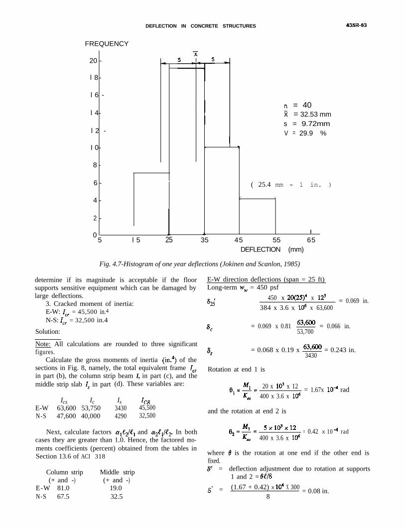
DEFLECTION IN CONCRETE STRUCTURES
FREQUENCY
20 -
l 8 -
l 6 -
l 4 -
l 2 -
I 0 -
8 -
6 -
4 -
2 -
0
( 25.4 mm = 1 in. )
r +
l
5 l 5 25 35 45 55 65DEFLECTION (mm)
n = 40- x = 32.53 mm
* s = 9.72mmV = 29.9 %
Fig. 4.7-Histogram of one year deflections (Jokinen and Scanlon, 1985)
determine if its magnitude is acceptable if the floorsupports sensitive equipment which can be damaged bylarge deflections.
3. Cracked moment of inertia:E-W: I,, = 45,500 in.4N-S: I,, = 32,500 in.4
Solution:
Note: All calculations are rounded to three significantfigures.
Calculate the gross moments of inertia (in.4) of thesections in Fig. 8, namely, the total equivalent frame Itsin part (b), the column strip beam I, in part (c), and themiddle strip slab Is in part (d). These variables are:
Ics IcE-W 63,600 53,750N-S 47,600 40,000
Is3430
ICR45,500
4290 32,500
Next, calculate factors c~#~/4?t and cy2$/e2. In bothcases they are greater than 1.0. Hence, the factored mo-ments coefficients (percent) obtained from the tables inSection 13.6 of ACI 318
Column strip Middle strip(+ and -) (+ and -)
E-W 81.0 19.0N-S 67.5 32.5
E-W direction deflections (span = 25 ft)Long-term w, = 450 psf
s2;450 x 20(25)4 x 123 = 0.069 in.
384 x 3.6 x lo6 x 63,600
s =C
0.069 x 0.81 63,600 = 0.066 in.53,700
sS= 0.068 x 0.19 x !!?@!!f = 0.243 in.
3430
Rotation at end 1 is
8 Ml 20 x ld x 12z-zl &c
= 1.67x 10m4 rad400 x 3.6 x lo6
and the rotation at end 2 is
8 M2 5xldx122=c= = 0.42 X 10 -4
400 x 3.6 x lo6rad
where 8 is the rotation at one end if the other end isfixed.sN = deflection adjustment due to rotation at supports
1 and 2 = M/8
O S" = (1.67 + 0.42) X 1~ X 300 = 0.08 in. in8
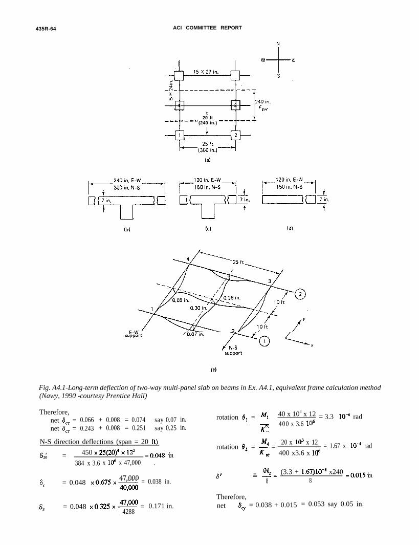
435R-64 ACI COMMITTEE REPORT
F(
,%.-----------u--Xu3 -
-- 4 -
t20 fte-----m
(240 in.) ---*---
support
support
ig. A4.1-Long-term deflection of two-way multi-panel slab on beams in Ex. A4.1, equivalent frame calculation methodNawy, 1990 -courtesy Prentice Hall)
Therefore,net SCs = 0.066 + 0.008 = 0.074 say 0.07 in.net 6, = 0.243 + 0.008 = 0.251 say 0.25 in.
N-S direction deflections (span = 20 ft)
o S20 ' = 450 ~25(20)~ ~12~ =oo48l
in
384 x 3.6 x lo6 x 47,000
6,47,000
= 0.048 x0.675x- = 0.038 in.4WoO
o Ss = 0.048 x0.325x- =479m 0.171 in.4288
rotation 6, = 4 40 x 103 x 12 = 3.3K
10m4 radcc 400 x 3.6 lo6
M4rotation 0, = K =20 x ld x 12 = 1.67 x 10B4 rad
cc 400 x3.6 x lo6
s N 0~-m-E (3.3 + 1.67)10-4 x240 =oo15 in. .8 8
Therefore,net 6, = 0.038 + 0.015 = 0.053 say 0.05 in.

DEFLECTION IN CONCRETE STRUCTURES 435R-65
o S9) = 0.171 + 0.015 = 0.186 say 0.19 in.
total central deflection ^ _ = as + iSq = $, + 6,
^ _ E-W = aa + s, = 0.25 + 0.05 = 0.30 in.
^ _N-S = ar + s, = 0.19 + 0.07 = 0.26 in.Hence, the average deflection at the center of the
interior panel ?4(AEBw + ANss) = 0.28 in. (7 mm).
Adjustment for cracked section: Use Branson’s effectivemoment of inertia equation,
Mcr 3Ma I
L
frMcr = 3
yt
M3Ie= 2 Ig + l-il 1Ma
Calculation of ratio A4JIa:
where f, = modulus of rupture of concreteYt = distance of center of gravity of section from
outer tension fibersE-W (240-in. flange width): yt = 21.5 in.N-S (300 in. flange width): y, = 19.2 in.
f, = 7.5g = 7.4JZiRB = 474 psi
Hence,
Mcp-w) 474= x 63 , 600 ’ =⌧E
1l 17 x105 ft-lb21.5
M,(N-s)
474= x 47, 000 ’ = 0.9 7 x 105 ft-lb19.2 ⌧E
wpinterior panel hIa = - = 20 x 450(25)2 forE-W
16 16= 3.52 x lo5 ft-lb
25 x 450(20)2 for N-S16
= 2.81 x 10’ ft-lb
Note that the moment factor l/16 is used to be onthe safe side, although the actual moment coefficients fortwo-way action would have been smaller.
E-W effective moment of inertia Ze
MCr
-= 1.17 x lo5 = 0.332l
Ma 3.52 x lti
( IMcr 3 = 0.037 - -Pal
I e = 0.037 x 63,600 + (1 - 0.037)45,500 = 46,200 in.4
N-S effective moment of inertia I4
Mcr-= 0-97 x l@ = 0.345lMa 2.81 x 10⁵
Mcr 3i I = 0.041
Ma
Ie = 0.041 x 47,000 + (1 - 0.041)32,500 = 33,100 in.4
4 47,000
K+
33,100= 1.40
l
Q-= 25Jt x 12 = 769 > 480 allowed in Table 4.2.o S 0.39
Adjusted central deflection for cracked section effect= 1.40 x 0.28 = 0.39 in. (10 mm)
Hence, the long-term central deflection is acceptable.
Example A4.2-Deflection calculation for a flat plateusing the crossing beam method
An edge panel of 6 in. (150 mm) flat plate withmultiple panels in each direction is shown in Fig. A4.2.
The mid-panel deflection is computed as the sum ofthe column strip deflection in the N-S direction and themiddle strip deflection i the E-W direction. Moments atunfactored load level due to dead plus live load are givenin Table A4.1.Cracking moment (A&,.)
fr= 4 K (significant restraint)= 219 psi
The plate is supported on 16 in. x 16 in. (406 mm x 406mm) columns. The slab is designed for an unfactored liveload of 60 psf (2.87 kPa) in addition to its self-weight of75 psf (3.59 kPa). Assume that the slab is subjected tosignificant in-plane restraint. Check the live load de-flection and incremental deflection at mid-panel if non-structural components are installed one month after re-moval of shoring. Material properties are:
fc ' = 3000 psi (20.7 MPa)fy
= 60,000 psi (414 MPa)EC
= 3.12 x 10d psi (21,500 MPa)
Using Eq. 4.4, deflection of column and middle stripscan be obtained from
o S 5enE-- [Mm + 0.1 (M, + MO)]
48 EcZe
in which moments and Ie are computed for a strip of unitwidth.
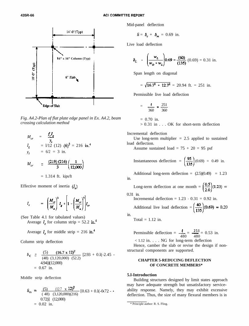
435R-66
16” x 16” Column (Typ)I
Fig. A4.2-Plan of flat plate edge panel in Ex. A4.2, beamcrossing calculation method
Mcr = ‘8
y*‘g = l/12 (12) (6)3 = 216 in.4
yt = 6/2 = 3 in.
Mel. =
= 1.314 ft. kips/ft
Effective moment of inertia (1J
(See Table 4.1 for tabulated values)Average 1e for column strip = 52.2 in.4
Average I& for middle strip = 216 in.4
Column strip deflection
s - (5) (16.7 x 12)*c -
(48) (3,120,000) (52.2)[2.93 + 0.l(-2.45 -
4.94)](12,000)= 0.67 in.
Middle strip deflection
o S _ (5) (12.7 x 12)*m- [0.63 + 0.l(-0.72 -
( 48) (3,120,000)(216) -
0.72)] (12,000)= 0.02 in.
Mid-panel deflection
o S = SC + Sm = 0.69 in.
Live load deflection
SL = (0.69) = 0.31 in.
Span length on diagonal
= /iii??%? = 20.94 ft. = 251 in.
Permissible live load deflection
4 251= -=-360 360
= 0.70 in.> 0.31 in . . . OK for short-term deflection
Incremental deflectionUse long-term multiplier = 2.5 applied to sustained
load deflection.
in.
Assume sustained load = 75 + 20 = 95 psf
Instantaneous deflection = (0.69) = 0.49 in.
Additional long-term deflection = (2.5)(0.49) = 1.23
Long-term deflection at one month =
0.31 in.Incremental deflection = 1.23 - 0.31 = 0.92 in.
Additional live load deflection =
in.Total = 1.12 in.
Permissible deflection = -!- = - = 0.53 in.2 5 1480 480
< 1.12 in. . . . NG for long-term deflectionHence, camber the slab or revise the design if non-
structural components are supported.
CHAPTER 5-REDUCING DEFLECTIONOF CONCRETE MEMBERS*
5.l-IntroductionBuilding structures designed by limit states approach
may have adequate strength but unsatisfactory service-ability response. Namely, they may exhibit excessivedeflection. Thus, the size of many flexural members is in
* Principle author: R. S. Fling.
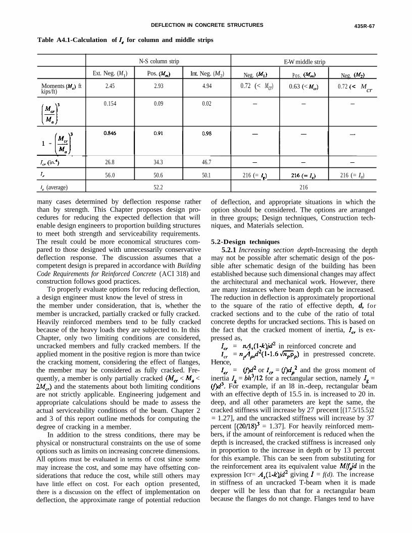
DEFLECTION IN CONCRETE STRUCTURES 435R-67
Table A4.1-Calculation of 1, for column and middle strips
Ext. Neg. (M1)
N-S column strip
Pos. (M,) Int. Neg. (M2) Neg. (Ml)
E-W middle strip
P o s . (M,) Neg. (M,)
Moments (hf,) ft 2.45 2.93 4.94 0.72 (< Mcr)kips/ft)
0.63 (< M,) 0.72 (< Mcr
0.154 0.09 0.02 - - -
~~~
I,, (in.4) 26.8 34.3 46.7 - - -
Z, 56.0 50.6 50.1 216 (= Z,) 216(=Z) 216 (= Ig)
I, (average) 52.2 216
many cases determined by deflection response ratherthan by strength. This Chapter proposes design pro-cedures for reducing the expected deflection that willenable design engineers to proportion building structuresto meet both strength and serviceability requirements.The result could be more economical structures com-pared to those designed with unnecessarily conservativedeflection response. The discussion assumes that acompetent design is prepared in accordance with BuildingCode Requirements for Reinforced Concrete (ACI 318) andconstruction follows good practices.
To properly evaluate options for reducing deflection,a design engineer must know the level of stress inthe member under consideration, that is, whether themember is uncracked, partially cracked or fully cracked.Heavily reinforced members tend to be fully crackedbecause of the heavy loads they are subjected to. In thisChapter, only two limiting conditions are considered,uncracked members and fully cracked members. If theapplied moment in the positive region is more than twicethe cracking moment, considering the effect of flanges,the member may be considered as fully cracked. Fre-quently, a member is only partially cracked (M, < M, <2M,,) and the statements about both limiting conditionsare not strictly applicable. Engineering judgement andappropriate calculations should be made to assess theactual serviceability conditions of the beam. Chapter 2and 3 of this report outline methods for computing thedegree of cracking in a member.
In addition to the stress conditions, there may bephysical or nonstructural constraints on the use of someoptions such as limits on increasing concrete dimensions.All options must be evaluated in terms of cost since somemay increase the cost, and some may have offsetting con-siderations that reduce the cost, while still others mayhave little effect on cost. For each option presented,there is a discussion on the effect of implementation ondeflection, the approximate range of potential reduction
of deflection, and appropriate situations in which theoption should be considered. The options are arrangedin three groups; Design techniques, Construction tech-niques, and Materials selection.
5.2-Design techniques5.2.1 Increasing section depth-Increasing the depth
may not be possible after schematic design of the pos-sible after schematic design of the building has beenestablished because such dimensional changes may affectthe architectural and mechanical work. However, thereare many instances where beam depth can be increased.The reduction in deflection is approximately proportionalto the square of the ratio of effective depth, d, forcracked sections and to the cube of the ratio of totalconcrete depths for uncracked sections. This is based onthe fact that the cracked moment of inertia, I,, is ex-pressed as,
I,, = nA,(l-Qd2 in reinforced concrete andIcr
Hence,= n#d2(1-1.6 \/npp,) in prestressed concrete.
1,, = @d2 or Z,, = @dP2 and the gross moment ofinertia Jg = bh3/12 for a rectangular section, namely lg =@)d3. For example, if an l8 in.-deep, rectangular beamwith an effective depth of 15.5 in. is increased to 20 in.deep, and all other parameters are kept the same, thecracked stiffness will increase by 27 precent [(17.5/15.5)2= 1.27], and the uncracked stiffness will increase by 37percent [(20/18)3 = 1.37]. For heavily reinforced mem-bers, if the amount of reinforcement is reduced when thedepth is increased, the cracked stiffness is increased onlyin proportion to the increase in depth or by 13 percentfor this example. This can be seen from substituting forthe reinforcement area its equivalent value Mfljd in theexpression Icr= A#-Qd2 giving I = f(d). The increasein stiffness of an uncracked T-beam when it is madedeeper will be less than that for a rectangular beambecause the flanges do not change. Flanges tend to have

435R-68 ACI COMMITTEE REPORT
a fixed influence rather than a proportional influence onuncracked stiffness.
If, by increasing the depth, the concrete tensile stressin a member is reduced sufficiently so that it changesfrom a cracked, or partially cracked, to an uncrackedmember, the stiffness could increase dramatically. Theuncracked stiffness can be as much as three times thepartially cracked stiffness (Grossman, 1981).
5.2.2 Increasing section width-This option is notapplicable to slabs or other members with physicalconstraints on their width. Where beams cannot be madedeeper because of floor to floor height limitations, butcan be made wider, the increase in stiffness is propor-tional to the increase in width if the member is un-cracked. If the member is cracked and remains crackedafter increasing the width, the increase in stiffness is verysmall. However, if a cracked member becomes uncrackedbecause the width is increased, its stiffness increasesappreciably, possibly by as much as a factor of three(Grossman, 1981).
5.2.3 Addition of compression reinforcement-UsingACI 318 procedures, compression reinforcement hassome effect on immediate deflection as it can influenceIC,; thus I, will be affected, as will the initial deflection,however small the influence is. But it can reduce addi-tional long-term or incremental deflection up to about 50percent (ACI 318, 1989). The effect on total deflectionis somewhat less. The addition of compression rein-forcement reduces the additional long-term deflection inthe example to 0.50 in. or by 50 percent and the totaldeflection to 1.00 in. or by 33 percent.
Long-term deflection has two components, creep de-flection and shrinkage warping. Compression reinforce-ment reduces deflection because concrete creep tends totransfer the compression force to the compression rein-forcement which does not itself creep. The closer thereinforcement is to the compression face of the member,the more effective steel reinforcement is in reducinglong-term creep deflection. Thus, compression reinforce-ment is more effective in deeper than in shallower beamsor slabs if the concrete cover to the compression face ofthe member is of constant value. For some very shallowmembers, due to the requirements of minimum barcover, compression reinforcement could be at or near theneutral axis and be almost totally ineffective in reducinglong-term creep deflection.
Shrinkage warping occurs where the centroids of thesteel reinforcement and the concrete do not coincide andthe shrinkage of concrete, combined with the dimensionalstability of steel reinforcement, warps the member in afashion similar to a piece of bimetal subject to temper-ature variations. Compression reinforcement reducesshrinkage warping because it brings the centroid of thetension and compression reinforcement closer to the con-crete neutral axis. While compression reinforcement re-duces shrinkage and warping of all flexural members, itis especially effective for T-beams where the neutral axisis close to the compression face and far from the tension
reinforcement. If the T-beam has a thin slab subiect tohigher than normal shrinkage because of its high surface-to-volume ratio, then compression reinforcement will bemore effective than for a rectangular beam. This will betrue for ribbed slabs or joist systems as well.
5.2.4 Addition of tension reinforcement-For un-cracked members, addition of tension reinforcement hashardly any effect on deflection. For fully cracked mem-bers, addition of tension reinforcement reduces bothimmediate and long-term deflection almost in proportionto the increase in the steel reinforcement area. This canbe seen from the cracked moment of inertia, I,,, definedin Section 5.2.1. For all practical purposes IO = 0.9A,since the variation in the term (1-k)j is usually small. Forexample, if the total deflection of a cracked member is1.50 in. as in the previous example, increasing the tensionreinforcement by 50 percent will reduce the deflection toabout 1.10 in. However, the increased reinforcement areashould still be less than the maximum permitted by AC1318, namely a maximum of 0.75 times the balanced ratiopb. This option is most useful for lightly reinforced solidand ribbed slabs. The option of adding more tension re-inforcement is not available or is limited for heavilyreinforced beams unless compression reinforcement isalso added to balance the increase in tension bar area inexcess of 0.75 pb.
5.2.5 Prestressing application-Dead load deflection ofreinforced concrete members may be reduced substantial-ly by the addition of prestressing. However, deflections inprestressed concrete members due to live load and othertransient loads are about the same as those in reinforcedconcrete members of the same stiffness, EI. If prestress-ing keeps the member in an uncracked state, withoutwhich it would otherwise crack, the live load deflectionwould be considerably smaller. If, however, the pre-stressed member size is reduced, as is usually the case inorder to take advantage of prestressing, then the liveload deflection becomes larger.
Consequently, the span/depth ratio in post-tensionedtwo-way floors is normally limited to 48 in lower floorslabs with light live load and 52 in roof slabs (ACI 318Section R18.2.3, 1989). If the member has a high ratio oflive to dead load, then the span/depth ratio must beproportionally reduced in order to give satisfactorydeflection performance. A prestressing force sufficient toproduce satisfactory deflection response should always beprovided, regardless of whether the member is uncrackedat service load or it is designed as partially prestressedwith tolerable flexural crack width levels which are con-trolled by additional mild steel reinforcement.
5.2.6 Revision of structure geometry-Common solu-tions to reduce deflections include increasing the numberof columns in order to reduce the length of the spans,adding cross members to create two-way systems, and in-creasing the size of columns to provide more end re-straint to flexural members.
5.2.7 Revision of deflection Limit criteria-If deflectionof a member is “excessive,” the deflection limits may be

DEFLECTION IN CONCRETE STRUCTURES 435R-69
re-examined to determine if they are unnecessarily re-strictive. If experience or analysis indicates that thoselimits (see Chapters 2 and 3) can be relaxed, then otheraction might not be required. Many building codes donot set absolute limits on deflection. An engineer mightdetermine that the building occupancy, or constructionconditions, such as a sloping roof, do not require thenormal deflection limits.
5.3-Construction techniques5.3.1 Concrete curing to allow gain in strength-
Deflection response is determined by concrete strengthat first loading, not by final concrete strength. If theconstruction schedule makes early loading of the con-crete likely or desirable, then measures to ensure high-strength at first loading or construction loading can beeffective. For example, if at the design compressivestrength f’c of 4000 psi, the member would be uncrackedas designed, but it is loaded when concrete strength is2500 psi, it could be excessively cracked due to a lowermodulus of rupture at the time of loading. Even thoughits final load-carrying capacity was satisfactory, thecracked member could still deflect several times morethan a similar uncracked one. Furthermore, the modulusof elasticity of a 4000 psi concrete is higher than that of2500 psi concrete (see Section 5.4 of this report for theeffects of material selection on these parameters).
5.3.2 Concrete curing to reduce shrinkage and creep-Immediate deflection will not be greatly affected byconcrete curing but additional long-term deflection willbe reduced. Assuming the long-term component of de-flection is evenly divided between shrinkage and creep, ifshrinkage is reduced 20 percent by good curing, the addi-tional long-term deflection due to shrinkage will be re-duced by 10 percent. The effect will be most pronouncedon members subject to high shrinkage such as those witha high surface/volume ratio (smaller members), thosewith thin flanges, and structures in arid atmospheres ormembers which are restrained. The effect of good curingon creep is similar to its effect on shrinkage.
5.3.3 Control of shoring and reshoring procedures-Many studies indicate that the shoring load on floors ofmulti-story buildings can be up to twice the dead weightof the concrete slab itself. Because the design super-imposed load is frequently less than the concrete selfweight, the slab may be seriously overstressed andcracked due to shoring loads instead of remaining un-cracked as assumed by calculations based on designloads. Thus, the flexural stiffness could be reduced to aslittle as one third of the value calculated assuming designloads only. Furthermore, the shoring loads may be im-posed on the floor slabs before the concrete has reachedits design strength (see discussion in Section 5.3.1).
Construction of formwork and shoring should ensurethat a sag or negative camber is not built into the slab.Experience indicates that frequently the apparent deflec-tion varies widely between slabs of identical design andconstruction. Some reasons for this may be that such
slabs were not all built level or at the specified grade orthe method and timing of form stripping was not uni-formly applied. Also, construction loads may not havebeen applied uniformly.
5.3.4 Delay of the first loading-This allows the con-crete to gain more strength before loading or helps toreach its design strength. Both the modulus of elasticityEC and the modulus of rupture& will be increased. Anincrease in E, increases the flexural stiffness. An increasein the modulus of rupture value, f, reduces the amountof cracking or even allows the member to remain un-cracked with an increase in flexural stiffness EI as notedin the next section.
5.3.5 Delay in installation of deflection-sensitiveelements or equipment-Such delay in equipment installa-tion will have no effect on immediate or total deflection,except as previously noted in 5.3.1. But incremental de-flection will be reduced, namely the deflection occurringfrom the time a deflection-sensitive component is in-stalled until it is removed or the deflection reaches itsfinal value. For example, if the additional long-termdeflection is 1.00 in., and installation of partitions isdelayed for 3 months, the incremental deflection will beapproximately 0.50 in. or about one-half as much as thetotal deflection.
5.3.6 Location of deflection-sensitive equipment toavoid deflection problems-Equipment such as printingpresses, scientific equipment and the like must remainlevel and should be located at mid-span where thechange in slope is very small with the increase indeflection. On the other hand, because the amplitude ofvibration is highest at mid-span, vibration-sensitiveequipment may be best located near the supports.
5.3.7 Provision of architectural details to accommodateexpected deflection-Partitions that abut columns, as anexample, may show the effect of deflection by separatinghorizontally from the column near the top even thoughthe partition is not cracked or otherwise damaged. Archi-tectural details should accommodate such movements.Likewise, windows, walls, partitions, and other non-structural elements supported by or located under de-flecting concrete members should be provided with slipjoints in order to accommodate the expected deflectionsor differential deflections between concrete membersabove and below the non-structural elements.
5.3.8 Building camber into floor slabs-Built in camberhas no effect on the computed deflection of a slab. How-ever, cambering is effective for installation of partitionsand equipment, if the objective is to have a level floorslab after deflection takes place. For best results, de-flection must be carefully calculated using the appro-priate modulus of concrete E, value and the correctmoment of inertia I. Overestimating the deflection valuecan lead the designer to specify unreasonable overcam-bering. Hence, the pattern and value of cambering atseveral locations has to be specified and the resultsmonitored during construction. Procedures have to berevised as necessary for slabs which are to be constructed
435R.70 ACI COMMITTEE REPORT
at a later date.5.3.9 Ensuring that top bars are not displaced down-
ward-Downward displacement of top bars always re-duces strength. The effect on deflection in uncrackedmembers is minimal. But its effect on cracked members,namely those that are heavily loaded, is in proportion tothe square of the ratio of change in effective depths forcantilevers but much less for continuous spans. This re-duced effect in continuous members is because the flex-ural stiffness and resulting deflection of the member isdetermined primarily by member stiffness at the midspansection. Thus, the deflection of cantilevers is particularlysensitive to misplacement of the top reinforcing bars.Deflection could increase, in continuous members, if thereduction in strength at negative moment regions resultsin redistribution of moments.
5.4-Materials selection5.4.1 Selection of materials for mix design that reduce
shrinkage and creep or increase the moduli of elasticity andrupture-Materials having an effect on these propertiesinclude aggregates, cement, silica fume, and admixtures.Lower water/cement ratio, a lower slump and changes inother materials proportions can reduce shrinkage andcreep or increase the moduli of elasticity or rupture.
5.4.2 Use of concretes with a higher modulus of elas-ticity-Using AC1 318 procedures, the stiffness of anuncracked member increases in proportion to the elasticmodulus which varies in proportion to the square root ofthe cylinder strength. (ACI 318, 1989, Sections 9.5.2.2and 8.5) The stiffness of a cracked section is affectedlittle by a change in the modulus of elasticity.
5.4.3 Use of concretes with a higher modulus of rupture-Concrete with a higher modulus of rupture does notnecessarily increase the stiffness of uncracked membersand highly cracked members. Stiffness of partiallycracked members increases because of the reduction ofthe degree of cracking. The increase in stiffness (decreasein deflection) depends on steel reinforcement percentage,the increase in modulus of rupture, and the magnitude ofapplied moment.
5.4.4 Addition of short discrete fibers to the concretemix--Such materials have been reported to reduceshrinkage and increase the cracking strength, both ofwhich might reduce deflection (Alsayed, 1993).
5.5-SummaryTable 5.1 summarizes some of the preventive mea-
sures needed to reduce or control deflection. This tablecan serve as a general guide to the design engineer butis not all inclusive, and engineering judgement has to beexercised in the choice of the most effective parametersthat control deflection behavior.
REFERENCES
Chapter 2“Building Code Requirements for Reinforced Con-
crete and Commentary,” ACI 318, American ConcreteInstitute, Detroit, Michigan, 1989, 353 pp.
“Prediction of Creep, Shrinkage, and TemperatureEffects in Concrete Structures,” SP-27, American Con.crete Institute, Detroit, 1971, pp. 51-93; SP-76, 1982, pp.193-300.
“Prediction of Creep, Shrinkage and TemperatureEffects in Concrete Structures,” American ConcreteInstitute, ACI-209R-92, Manual of Concrete Practice,1994, pp. l-47.
“State-of-the-Art Report on High Strength Concrete,”ACI JOURNAL, Proceedings, V. 81, No. 4, July-August1984, pp. 364-410.
“State-of-the-Art Report on Temperature-InducedDeflections of Reinforced Concrete Members,” SP-86,American Concrete Institute, Detroit, 1985, pp. 1-14.
ACI Committee 435, Building Code Subcommittee,“Proposed Revisions by Committee 435 to AC1 BuildingCode and Commentary Provisions on Deflections,” ACIJOURNAL, Proceedings, V. 75, No. 6, June 1978, pp. 229-238.
ACI Committee 435, Subcommittee 7, “Deflections ofContinous Concrete Beams,” ACI JOURNAL, Proceedings,V. 70, No. 12, Dec. 1973, pp. 781-787.
ACI Committee 435, Subcommittee 2, “Variability ofDeflections of Simply Supported Reinforced ConcreteBeams,” ACI JOURNAL, Proceedings, V. 69, No. 1, Jan.1972, pp. 29.35.
“Prediction of Creep, Shrinkage, and TemperatureEffects in Concrete Structures,” SP-27, American Con-crete Institute, Detroit, 1971, pp. 51-93.
ACI Committee 435, Subcommittee 1, “AllowableDeflections,” ACI JOURNAL, Proceedings, V. 65, No. 6,June 1968, pp. 433-444.
ACI Committee 435, “Deflections of Reinforced Con-crete Flexural Members”, ACI JOURNAL, Proceedings V.63, No. 6, June 1966, pp. 637-674.
Ahmad, S.H., and Shah, S.P., “Stress-Strain Curves ofConcrete Confined by Spiral Reinforcement,” ACIJOURNAL, Proceedings, V. 79, No. 6, Nov.-Dec. 1982, pp.484.490.
Al-Zaid, R., Al-Shaikh, A.H., and Abu-Hussein, M.,“Effect of Loading Type on the Effective Moment ofInertia of Reinforced Concrete Beams,” ACI StructuralJournal, V. 88, No. 2, March-April 1991, pp. 184-190.
ASCE Task Committee on Finite Element Analysisof Reinforced Concrete Structures, “Finite ElementAnalysis of Reinforced Concrete,” ASCE, 1982, NewYork, 545 pp.
Bazant, Z.P, Panula, L., “Creep and ShrinkageCharacterization for Analyzing Prestressed ConcreteStructures,” PCI Journal, V. 25, No. 3, May-June 1980,pp. 86-122.
Beeby, A.W., “Short Term Deformations of Rein-forced Concrete Members,” Cement and Concrete Asso-ciation Technical Report, TRA 408, London, Mar. 1968.
Branson, D.E., Chapter 2-“Deflections”, Handbook ofConcrete Engineering, Second Edition, Van Nortrand

DEFLECTION IN CONCRETE STRUCTURES 435R-71
Table 5.1-Deflection reducing options
Option Effect on section stiffness
Cracked Uncracked
Design techniques
1. Deeper members (h’fi)3 for rectangular beams. Less for T- (d’/d)2 or (do/d). If change to uncrackedbeams. section, up to 300 percent.
2. Wider members @*lb) Small unless changed to uncracked section.
3. Add As '
4. Add As
5. Add prestress
I I
Up to 50 percent for ALP No effect for Ai. 1 Up to 50 percent for ALP NO effect for Ai.
No effect. A,*/!,.
Reduces dead load deflection to nearly zero. Reduces dead load deflection to nearly zeroand member to uncracked.
6. Structural Large effect. Large effect.geometry
7. Revise criteria See text. See text.
Constructiontechniques
8. Cure: f,’ Same as higher E, and f, Same as higher E, and f, and could change touncracked section.
9. Cure: E, and E, For long-term deflection (Esh*/Es,,) and(%r*E&
For long-term deflection (E&*/IQ and(%r*Gr)*
10. Choring Large effect, see text. Large effect, see text.
11. Delay first Similar to options in Section 5.4. Similar to options in Section 5.4.loading
12. Delay installation Up to 50 percent+ depending on time delay. Up to 50 percent+ depending on time delay.
13. Locate equipment See text. See text.
14. Architectural See text. See text.details
15. Camber
16. Top bars
Materials
See text.
No effect.
See text.
Up to (d’/d)2 for cantilevers.
17. Materials
18. Mix design
19. Higher E,
20. Higher f,
21. Use fiberreinforcement.
See. Section 5.4.
See Sections 5.4.2 and 5.4.3.
(Ec*/Ec) or cfc’*lf,‘)os.
None.
See Sections 5.3.2 and 5.4.4.
See Section 5.4.
See Sections 5.4.2 and 5.4.3.
Small.
Significant.
See Sections 5.3.2 and 5.4.4.
* = a superscript denoting parameters that have been changed to reduce deflection.
^ _ = deflection.E = strains; ESh = shrinkage strain; and E, = creep strain.Other symbols are the same as those specified in the ACI 318-89 (Revised 1992) code.
.
,
Reinhold Co., New York, Editor, M. Fintel, 1985, pp. 53-78.
Branson, D.E., and Trost, H., “Unified Procedures forPredicting the Deflection and Centroidal Axis Locationof Partially Cracked Non-Prestressed Members,” ACIJOURNAL, Proceedings, V. 79, No. 2, Mar.-Apr. 1982, pp119-130.
Branson, D.E., Deformation of Concrete Structures,McGraw Hill Book Co., Advanced Book Program, NewYork, 1977, 546 pp.
Branson, D.E., and Cristianson, M.L., “Time-Depen-dent Concrete Properties Related to Design-Strengthand Elastic Properties, Creep and Shrinkage,” ACISpecial Publication, SP-27, 1971, pp. 257-277.
Branson, D.E., and Kripanarayanan, KM., “Loss ofPrestress, Camber and Deflection of Non-Composite andComposite Prestressed Concrete Structures,” PCI Journal,V. 16, Sept.-Oct. 1971, pp. 22-52.
Branson, D.E., “Compression Steel Effect on Long-Time Deflections,” ACI JOURNAL, Proceedings, V. 68

435R-72 ACI COMMITTEE REPORT
No. 8, Aug. 1971, pp. 555-559.Branson, D.E., “Instantaneous and Time-Dependent
Deflections of Simple and Continous Reinforced Con-crete Beams,” HPR Publication No.7, Part 1, AlabamaHighway Department, U.S. Bureau of Public Roads, Aug.1963, pp. l-78.
Carrasquillo, R.L., Nilson, A.H., and Slate, F.O.,“Properties of High Strengh Concrete Subjected to ShortTerm Loads,” ACI JOURNAL, Proceedings, V. 78, No. 3,May-June 1981, pp. 171-178.
CEB Commission IV, Deformations, PortlandCement Association, Foreign Literature Study 547, 1968.
Comite-International du Beton (CEB) - FederationInternationale de la Pricontrainte (FIP), Model Code forConcrete Structures, 1990, P.O. Box 88, CH-1015,Lausanne.
Ghali, A., “Deflection Prediction in Two-Way Floors,”ACI Structural Journal, V. 86, No. 5, Sept.- Oct. 1989, pp.551-562.
Ghali, A., and Favre, R., Concrete Structures: Stressesand Deformations, Chapman and Hall, London and NewYork, 1986, 352 pp.
Grossman, J.S., “Simplified Computations for Effec-tive Moment of Inertia (Ie) and Minimum Thickness toAvoid Deflection Computations,” ACI JOURNAL, Pro-ceedings, V. 78, No. 6, Nov.-Dec., 1981, pp. 423-439.Also, Author Closure, ACI JOURNAL, Proceedings, V. 79,No. 5, Sept.-Oct., 1982, pp. 414-419.
Grossman, J.S., “Reinforced Concrete Design,”Building Structural Design Handbook, R.N. White andC.G. Salmon, editors, John Wiley & Sons, New York,1987, Ch. 22, pp 699-786.
Hsu, C.T., “A Simple Nonlinear Analysis of Con-tinuous Reinforced Concrete Beams,” Journal of Engi-neering and Applied Science, V. 2, No. 4, 1983, pp. 267-276.
Hsu, C.T., and Mirza, M.S., “A Study of Post-Yielding Deflection in Simply Supported ReinforcedConcrete Beams,” ACI SP-43, Deflection of ConcreteStructures, American Concrete Institute, 1974, pp. 333-355, Closure, ACI JOURNAL, April 1975, pp. 179.
Luebkaman, C.H., Nilson, A.H., and Slate, F.O.,“Sustained Load Deflection of High Strength ConcreteBeams,” Research Report No. 85-2, Dept. of StructuralEngineering, Cornell University, February 1985.
Martin, I., “Effects of Environmental Conditions onThermal Variations and Shrinkage of Concrete Structuresin the United States,” SP-27, 1971, pp. 279-300.
Martinez, S., Nilson, A.H., and Slate, F.O., “Spirally-Reinforced High Strength Concrete Columns,” ResearchReport No. 82-10, Department of Structural Engineering,Cornell University, Ithaca, August 1982.
Meyers, B.L., and Thomas, E.W., Chapter 11, “Elasti-city, Shrinkage, Creep, and Thermal Movement of Con-crete,” Handbook of Structural Concrete, MaGraw Hill,New York, Editors, Kong, Evans, Cohen, and Roll, 1983,pp. 11.1-11.33.
Nagataki, S., and Yonekura, A., “Studies of the
Volume Changes of High Strength Concretes with Super-plasticizer,” Journal, Japan Prestressed ConcreteEngineering Association, V. 20, 1978, pp. 26-33.
Nawy, E.G., Reinforced Concrete - A FundamentalApproach, Second Edition, Prentice Hall, 1990, 738 pp.
Nawy, E.G., “Structural Elements: Strength, Service-ability and Ductility,” Handbook of Structural Concrete,McGraw Hill, New York, 1983, pp. 12.1-12.86.
Nawy, E.G., and Balaguru, P.N., “High Strength Con-crete,” Handbook of Structural Concrete, McGraw Hill,New York, 1983, pp. 5.1-5.33.
Nawy, E.G., and Neuworth, G., “Fiber Glass Rein-forced Concrete Slabs and Beams,” Structural DivisionJournal, ASCE, New York, pp. 421-440.
Ngab, AS., Nilson, A.H., and Slate, F.O., “Shrinkageand Creep of High Strength Concrete,” ACI JOURNAL,Proceedings, V. 78, No. 4, July-August 1981, pp. 255-261.
Nilson, A.H., “Design Implications of CurrentResearch on High Strength Concrete,” American Con-crete Institute, SP-87, 1985, pp. 85-117.
Nilson, A.H., Hover, K.C., and Paulson, K.A.,“Immediate and Long-Term Deflection of High StrengthConcrete Beams,” Report 89-3, Cornell University,Department of Structural Engineering, May 1989,230 pp.
Park, R., and Paulay, T., Reinforced ConcreteStructures, John Wiley & Sons, Inc., New York, 1975,769PP.
Pfeifer, D.W.; Magura, D.D.; Russell, H.G.; andCorley, W.G., “Time Dependent Deformations in a 70Story Structure,” SP-37, American Concrete Institute,1971, pp. 159-185.
Portland Cement Association, “Notes on ACI 318-83Building Code Requrements for Reinforced Concretewith Design Applications,” Skokie, Illinois, 1984.
Russell, H.G., and Corley, W.G., “Time-DependentBehavior of Columns in Water Tower Place,” SP-55,American Concrete Institue, 1978, pp. 347-373.
Saucier, K.L., Tynes, W.O., and Smith, E.F., “HighCompressive-Strength Concrete-Report 3, SummaryReport,” Miscellaneous Paper No. 6-520, U.S. ArmyEngineer Waterways Experiment Station, Vicksburg,September 1965, 87 pp.
Swamy, R.N., and Anand, K.L., “Shrinkage and Creepof High Strength Concrete,” Civil Engineering and PublicWorks Review, V. 68, No. 807, Oct. 1973, pp. 859-865,867-868.
Teychenne, D.C., Parrot, L.J., and Pomeroy, C.D.,“The Estimation of the Elastic Modulus of Concrete forthe Design of Structures,” Current paper No. CP23/78,Building Research Establishment, Garston, Watford,1978, 11 pp.
Yu, W.W., and Winter, G., “Instantaneous and Long-Term Deflections of Reinforced Concrete Beams UnderWorking Loads,” ACI JOURNAL, Proceedings, V. 57, No.1, 1960, pp. 29-50.
Wang, C.K., and Salmon, C.G., Reinforced ConcreteDesign 5th Edition, Harper Collins, 1992, pp. 1030.
II

DEFLECTION IN CONCRETE STRUCTURES 435R-73
,
Chapter 3ACI Committee 318, “Building Code Requirements
for Reinforced Concrete (318-89) and Commentary-ACI 318R-89,” American Concrete Institute, Detroit,1989.
ACI Committee 209, “Prediction of Creep, Shrinkage,and Temperature Effects in Concrete Structures,” Ameri-can Concrete Institute, SP-76, 1982, pp. 193-300.
ACI Committee 435, Subcommittee 5, Scordelis,A.C., Branson, D.E., and Sozen, M.A., “Deflections ofPrestressed Concrete Members,” Manual of ConcretePractice, ACI 435.1R-63 (Reapproved 1979), pp. 2-14,and ACI JOURNAL, Proceedings, V. 60, No. 12, Dec.1963, pp. 1697-1728.
ACI Committee 435, “Deflections of ReinforcedConcrete Flexural Members,” ACI JOURNAL, ProceedingsV. 63, No. 6, part 1, June 1966, ACI Manual of ConcretePractice, Part 2: Structural Design, Structural Specifi-cations, Structural Analysis, 1967, 1972, pp. 637-674.
ACI Committee 209, Subcommittee 2, and Commit-tee 209, Prediction of Creep, Shrinkage and Tempera-ture Effects in Concrete Structures, in “Designing forEffects of Creep, Shrinkage and Temperature in Con-crete Structures,” SP-27, 1971, pp. 51-93.
ACI - ASCE Joint Committee 423, Prestressed Concrete Report, “Estimating Prestress Losses”, ConcreteInternational, V. 1, No. 6, June 1979.
ACI Committee 435, Designing Concrete StructuresFor Serviceability and Safety, SP-133, American ConcreteInstitute, Detroit, 1993, pp. 346.
Aswad, A., “Time-Dependent Deflections of Pre-stressed Members: Rational and Approximate Methods,”ACI Symposium on Creep and Shrinkage, February 22,1989, Atlanta, GA.
Aswad, A., “Rational Deformation Prediction ofPrestressed Members,” SP-86, American Concrete Insti-tute, Detroit, 1985, pp. 263-280.
Aswad, A., “Experience with Pre- and Post-CrackingDeflections of Pretensioned Members,” ACI SP-133,American Concrete Institute, Detroit, 1992, pp. 207-224.
ACI Committee 435, Subcommittee 2, and Commit-tee 435 “Variability of Deflections of Simply SupportedReinforced Concrete Beams,” ACI JOURNAL, ProceedingsV. 69, No. 1, Jan. 1972, p. 29-35, with discussion, D. E.Branson, ACI JOURNAL, Proceedings, V. 69, No. 7, July1972, pp. 449-450.
Bazant, Z. P., “Prediction of Concrete Creep EffectsUsing Age-Adjusted Effective Modulus Method,” ACIJOURNAL, Proceedings, V. 69, No. 4, April 1972, pp. 212-217.
Branson, D. E., and Trost, H., “Application of the I-Effective Method in Calculating Deflections of PartiallyPrestressed Members,” PCI Journal, V. 27, No. 6, Dec.1982, pp. 86-111.
Branson, D.E., and Ozell, A.M., “Camber in Pre-stressed Concrete Beams,” V. 57, No. 12, June 1961, pp.1549-1574.
Branson, D.E., and Christianson, M.L., “Time-Depen-
dent Concrete Properties Related to Design-Strength andElastic Properties, Creep, and Shrinkage,” SP 27, Amer-ican Concrete Institute, Detroit, 1971, pp. 257-277.
Branson, D.E., and Kripanarayanan, K.M., “Loss ofPrestress, Camber and Deflection of Non-composite andComposite Prestressed Concrete Structures,“PCI Journal,V. 16, Sept.-Oct. 1971, pp. 22-52.
Branson, D.E., “Compression Steel Effect on Long-Time Deflections,” A C I JOURNAL, Proceedings, V. 68No. 8, Aug. 1971, pp. 323-363.
Branson, D.E., and Shaikh, A.F., “Deflection ofPartially Prestressed Members,” SP-86, AmericanConcrete Institute, Detroit, 1985, pp. 323-363.
Branson, D. E., Deformation of Concrete Structures,New York: McGraw Hill, 1977, pp. 546.
Branson, D. E., “The Deformation of Non-Compositeand Composite Prestressed Concrete Members,” InDeflection of Concrete Structures, SP-43, AmericanConcrete Institute, Detroit, 1974, pp. 83-127.
Branson, D. E., and Trost, H., “Unified Proceduresfor Predicting the Deflection and Centroidal Axis Loca-tion of Partially Cracked Nonprestressed and PrestressedConcrete Members,” ACI JOURNAL, Proceedings, V. 79,No. 5, Oct. 1982, pp. 62-77.
Branson, D.E., “Instantaneous and Time-dependentDeflections of Simple and Continuous Reinforced Con-crete Beams,” HPR Publication 7, Part 1, l-78, AlabamaHighway Department, Bureau of Public Roads, Aug.1963.
Branson, D.E., “Design Procedures for ComputingDeflections,” ACI JOURNAL, Proceedings, V. 65, No. 9,Sept. 1968, pp. 730-742.
Branson, D.E., “The Deformation of Non-compositeand Composite Prestressed Concrete Members,” Deflec-tions of Concrete Structures, SP-43, American ConcreteInstitute, Detroit, MI, 1970.
Collins, M.P. and Mitchell, D., “Shear and TorsionDesign of Prestressed and Non-Prestressed ConcreteBeams,” PCI Journal, V. 25, No. 5, September-October1980.
Comite’ Euro-International du Beton (CEB) -Federation Internationale de la Precontrainte (FIP),Model Code for Concrete Structures, 1990, CEB, 6 rueLauriston, F-75116, Paris.
Dilger, W.H., “Creep Analysis of Prestressed Con-crete Structures Using Creep-Transformed Section Pro-perties,” PCI Journal, V. 27, No. 1, Jan.-Feb. 1982.
Elbadry, M.M. and Ghali, A., “Serviceability Designof Continuous Prestressed Concrete Structures,” PCIJournal, V. 34, V.l, January-February, 1989, pp. 54-91.
Ghali, A., “A Unified Approach for ServiceabilityDesign of Prestressed and Nonprestressed ReinforcedConcrete Structures,” PCI Journal, Vol. 31, No. 2, March-April 1986, 300 pp.
Ghali, A. and Favre, R., Concrete Structures: Stressesand Deformations, Chapman and Hall, London and NewYork, 1986, 300 pp.
Ghali, A., and Neville, A.M., Structural Analysis-A

435R-74 ACI COMMITTEE REPORT
A
Unified Classical and Matrix Approach, 3rd Edition,Chapman & Hall, New York, 1989, pp. 608409.
Herbert, T.J., “Computer Analysis of Deflections andStresses in Stage Constructed Concrete Bridges,” PCIJournal, V. 35, No. 3, May-June 1990, pp. 52-63.
Libby, J.R., Modem Prestressed Concrete, 3rd Edition,Van Nostrand Reinhold Company, New York, 1984, 635p .
Martin, D.L., “A Rational Method for EstimatingCamber and Deflection of Precast Prestressed Members,”PCI Journal, V. 22, No. 1, January-February, 1977, pp.100-108.
Mirza, M.S., and Sabnis, G.M., “Deflections of One-Way Slabs and Beams,” Proceedings of Symposium, ACICanadian Capital Chapter, Montreal, Canada, Oct. 1971,pp. 53-87.
Fling, R.S., “Practical Considerations in ComputingDeflection of Reinforced Concrete,” SP-133, AmericanConcrete Institute, Detroit, 1993, pp. 69-92.
Naaman, A.E., Prestressed Concrete Analysis andDesign-Fundamentals, First edition, McGraw Hill BookCo., New York, N.Y., 1982, 670 pp.
Naaman, A.E., “Time Dependent Deflection of Pre-stressed Beams by Pressure Line Method,” PCI Journal,V. 28, No. 2, April 1983, pp. 98-119.
Naaman, A.E., “Partially Prestressed Concrete:Review and Recommendations,” Journal of the PrestressedConcrete Institute 30 (1985), pp. 30-71.
Nawy, E.G., and Potyondy, J.G., “Deflection Behaviorof Spirally Confined Pretensioned Prestressed ConcreteFlanged Beams,” PCI Journal, V. 16, June 1971, pp. 44 -59.
Nawy, E.G., and Potyondy, J.G., “Flexural CrackingBehavior of Pretensioned Prestressed Concrete I- and T-Beams,” ACI JOURNAL, Proceedings, V. 68,1971, pp. 335-360.
Nawy, E.G. and Potyondy, J.G., authors’ closure anddiscussion by D. E. Branson of “Flexural Cracking Be-havior of Pretensioned Prestressed Concrete I- and T-Beams,” ACI JOURNAL, Proceedings, V. 68, No. 5, May1971, discussion and closure, ACI JOURNAL, ProceedingsV. 68, No. 11, Nov. 1971, pp. 873-877.
Nawy, E.G., and Huang, P.T., “Crack and DeflectionControl of Pretensioned Prestressed Beams,” Journal ofthe Prestressed Concrete Institute, V. 22 (1971), pp. 30-47.
Nawy, E.G., and Chiang, J.Y., “Serviceability Be-havior of Post-Tensioned Beams,” Journal of the Pre-stressed Concrete Institute, V. 25, 1980, pp. 74-95.
Nawy, E.G., Prestressed Concrete-A Fundamentalpproach, Prentice Hall, Englewood Cliffs, N.J., 1989,
738 pp.Nawy, E.G. and Balaguru, P.N.,“High Strength Con-
crete,” Handbook of Structural Concrete, McGraw Hill,New York, 1983, pp. 5.1-5.33.
Nilson, A.H., Design of Prestressed Concrete, NewYork: Wiley, 1987, pp 592.
Neville, A. M., and Dilger, W., Creep of Concrete:Plain, Reinforced, and Prestressed, North-Holland
Publishing Company, Amsterdam, 1970, 622 pp.Prestressed Concrete Institute, PCI Design Handbook,
Chicago, Illinois, Fourth Edition, 1993.PCI Committee on Prestress Losses, “Recommenda-
tions for Estimating Prestress Losses,” Journal of thePrestressed Concrete Institute, V. 20, No. 4, July-August1975.
Rangan, B.V., “Serviceability Design in CurrentAustralian Code,” SP-133, American Concrete Institute,Detroit 1993, pp. 93-110.
Shaikh, A.F. and Branson, D.E., “Non-TensionedSteel in Prestressed Concrete Beams,” PCI Journal, V. 15,No. 1, Feb. 1970, pp. 14-36.
Sirosh, S.N. and Ghali, N.,“Reinforced ConcreteBeam-Columns and Beams on Elastic Foundation,”Journal of Structural Engineering, ASCE, V. 115, No.3,March 1989, pp. 666-682.
Tadros, M.K., “Expedient Service Load Analysis ofCracked Prestressed Concrete Sections,” PCI Journal, V.27, No. 6, Nov.-Dec. 1982, pp. 86-101.
Tadros, M.K., Ghali, A., and Dilger, W.H., “Effect ofNon-Prestressed Steel on Prestressed Loss and Deflec-tion,” PCI Journal, Vol. 22, No. 2, March 1977, pp. 50.
Tadros, M.K., ‘Expedient Service Load Analysis ofCracked Prestressed Concrete Sections,” PCI Journal, V.27, Nov.-Dec. 1982, pp. 86-111. Also, see Discussion byNilson, Branson, Shaikh, et al., PCI Journal, V. 28, No.6, Nov.-Dec. 1983.
Tadros, M.K., and Sulieman, H., Discussion of“Unified Procedures for Predicting Deflections,” byBranson and Trost, PCI Journal, V. 28, No. 6, Nov.-Dec.,1983, pp. 131-136.
Tadros, M.K., Ghali, A., and Meyer, A.W., “PrestressLoss and Deflection of Precast Concrete Members,” PCIJournal, V. 30, No. 1, January-February 1985.
Tadros, M.K., and Ghah, A., “Deflection of CrackedPrestressed Concrete Members” SP-86, AmericanConcrete Institute, Detroit, pp. 137-166.
Trost, H., “The Calculation of Deflections of Rein-forced Concrete Members-A Rational Approach,” SP-76, American Concrete Institute, Detroit, Michigan, 1982,pp. 89-108.
Chapter 4“Prediction of Creep, Shrinkage, and Temperature
Effects in Concrete Structures,”ACI 209R-82 (Revised1986), American Concrete Institute, Detroit, 1982.
“Control of Cracking in Concrete Structures,” ACI224R-80 (Revised 1984), American Concrete Institute,Detroit, 1980.
“Building Code Requirements for ReinforcedConcrete (AC1 318-89)(Revised 1992) and Commen-tary-ACI 318R-89 (Revised 1992),” American ConcreteInstitute, Detroit, 1992, 345 pp.
“Recommended Practice for Concrete Formwork,”ACI 347-78, American Concrete Institute, Detroit, 1978.
“Allowable Deflections,” ACI 435.3R-68 (Reapproved1989), American Concrete Institute, Detroit, 1968,12 pp.

DEFLECTION IN CONCRETE STRUCTURES 435R-75
,
.
“Variability of Deflections of Simply SupportedReinforced Concrete Beams,” AC1 435.4R-72 (Reap-proved 1989), American Concrete Institute, Detroit,1972, 7 pp.
“Deflection of Two-Way Reinforced Concrete FloorSystems: State-of-the-Art Report,” ACI 435.6R-74(Reapproved 1989), American Concrete Institute,Detroit, 1974, 24 pp.
“Observed Deflection of Reinforced Concrete SlabSystems, and Causes of Large Deflections,” ACI 435, 8R-85 (Reapproved 1991), American Concrete Institute,Detroit, 1985.
“Flexural Strength of Concrete Using Simple Beam withCenter Point Loading,” ASTM C 293-79, AmericanSociety for Testing and Materials.
Aguinaga-Zapata, M., and Bazant, Z.P.,” CreepDeflections in Slab Buildings and Forces in ShoresDuring Construction,” ACI JOURNAL , Proceedings, V. 83,No. 5, 1986, pp. 719-726.
ASCE Task Committee on Finite Element Analysisof Reinforced Concrete Structures, “Finite ElementAnalysis of Reinforced Concrete,” American Society ofCivil Engineers, New York, 1982, 553 pp.
Branson, D.E.,“Instantaneous and Time-DependentDeflections of Simple and Continuous ReinforcedConcrete Beams,” HPR Publication 7, Part 1, AlabamaHighway Department, Bureau of Public of Roads, Aug.,1963, pp. l-78.
Branson, D.E.,“Deformation of Concrete Structures,”McGraw-Hill Book Company, New York, 1977, 546 pp.
Cook, R.D., “Concepts and Applications of FiniteElement Analysis,” John Wiley and Sons, 1974.
Gallagher, R. H., “Finite Element Analysis: Funda-mentals,” Prentice-Hall, Inc., New Jersey, 1975.
Gardner, N.J., “Shoring, Re-shoring and Safety,”Concrete International, V. 7, No. 4, 1985, pp. 28-34.
Ghali, A., “Deflection Prediction in Two-Way Floors,”ACI Structural Journal, V. 86, NO. 5, 1989, pp. 551-562.
Ghali, A., “Deflection of Prestressed Concrete Two-Way Floor Systems,” ACI Structural Journal, V. 87, No. 1,1989, pp. 60-65.
Ghali, A., and Favre, R., “Concrete Structures:Stresses and Deformations,” Chapman and Hall, Londonand New York, 1986, 350 pp.
Ghosh, S.K,“Deflections of Two-Way ReinforcedConcrete Slab Systems,” Proceedings, InternationalConference on Forming Economical Concrete Buildings,Portland Cement Association, Skokie, 1982, pp.29.1-29.21.
Gilbert, R.I.,“Deflection Control of Slabs UsingAllowable Span to Depth Ratios,” ACI JOURNALProceedings, V. 82, No. 1, Jan.-Feb. 1985, pp. 67-77.
Gilbert, R.I.,“Determination of Slab Thickness inSuspended Post-Tensioned Floor Systems,” V. 86, No. 5,Sep.-Oct. 1989, pp. 602-607.
Graham, C.J., and Scanlon, A., “Deflection of Rein-forced Concrete Slabs under Construction Loading,”SP-86, American Concrete Institute, Detroit, 1986.
Graham, C.J., and Scanlon, A., “Long Time Multi-pliers for Estimating Two-Way Slab Deflections,” ACIJOURNAL, Proceedings, V. 83, No. 5, 1986, pp. 899-908.
Grossman, J.S., “Simplified Computations for Effec-tive Moment of Inertia le and Minimum Thickness toAvoid Deflection Computations,” ACI JOURNAL, Pro-ceedings, V. 78, No. 6, Nov.-Dec. 1981, pp. 423-439.
Grossman, J.S., Chapter 22, Building Structural DesignHandbook, R.N. White and C.G. Salmon editors, JohnWiley and Sons, 1987.
Grundy, P., and Kabila, A., “Construction Loads onSlabs with Shored Formwork in Multi-story Buildings,”ACI JOURNAL, Proceedings, V. 60, No. 12, December1963, pp. 1729-1738.
Jensen, V.P., “Solutions for Certain Rectangular SlabsContinuous Over Flexible Supports,” University of IllinoisEngineering Experimental Station Bulletin No. 303, 1938.
Jokinen, E.P., and Scanlon, A., “Field MeasuredTwo-Way Slab Deflections,” Proceedings, 1985 AnnualConference, CSCE, Saskatoon, Canada, May 1985.
Kripanarayanan, K.M., and Branson, D.E., “Short-Time Deflections of Flat Plates, Flat Slabs, and Two-WaySlabs,” ACI JOURNAL, Proceedings, V. 73, No. 12,December 1976, pp. 686-690.
Lin, T. Y., “Load-Balancing Method for Design andAnalysis of Prestressed Concrete Structures,” ACIJOURNAL, Procedings, V. 60, 1963, pp. 719-742.
Liu, X., Chen, W.F., and Bowman, M.D., “Construc-tion Load Analysis for Concrete Structures,” Journal ofStructural Engineering, V. 111, No. 5,1985, pp. 1019-1036.
Meyers, B.L. and Thomas, E.W., Chapter 11, “Elasti-city, Shrinkage, Creep and Thermal Movement of Con-crete,” Handbook of Structural Concrete, McGraw Hill,New York, 1983, pp. 11.1-11.33.
Nawy, E.G., Reinforced Concrete-A FundamentalApproach, 2nd edition, Prentice-Hall, 1990, 738 pp.
Nawy, E.G., Prestressed Concrete-A FundamentalApproach, Prentice Hall, 1989, 739 pp.
Nawy, E.G., and Neuewrth, G., “Fiber Glass Rein-forced Concrete Slabs and Beams,” Structural Division,ASCE Journal, 1977, pp. 421-440.
Nilson, A.H., and Walters, D.B. Jr., “Deflection ofTwo-Way Floor Systems by the Equivalent FrameMethod,” ACI JOURNAL, Proceedings, V. 72, No. 5, May1975, pp. 210-218.
“Design of Post-Tensioned Slabs,” Post-TensioningInstitute, Glenview Illinois, 1976, 52 pp.
Ramsay, R.J., Mina. S.A., and Macgregor, J.G.,“Monte Carlo Study of Short Time Deflections of Rein-forced Concrete Beams,” ACI JOURNAL, Proceedings, V.76, No. 8, August 1979, pp. 897-918.
Rangan, B.V., “Prediction of Long-Term Deflectionsof Flat Plates and Slabs,” ACI JOURNAL, Proceedings, V73, No. 4, April 1976, pp. 223-226.
Rangan, B.V., “Control of Beam Deflections byAllowable Span to Depth Ratios,” ACI JOURNAL, Pro-ceedings, V. 79, No. 5, Sept.-Oct. 1982, pp. 372-377.
Sbarounis, J.A., “Multi-story Flat Plate Buildings -

435R-76 ACI COMMITTEE REPORT
Construction Loads and Immediate Deflections,” Con-crete International, V. 6., No. 2, February 1984, pp. 70-77.
Sbarounis, J.A., “Multi-story Flat Plate Buildings:Measured and Computed One-Year Deflections,” Con-crete International, V. 6, No. 8, August 1984, pp. 31-35.
Scanlon, A., and Murray D. W., “Practical Calculationof Two-Way Slab Deflections,” Concrete International,November 1982, pp. 43-50.
Simmonds, S.H., “Deflection Considerations in theDesign of Slabs,” ASCE National Meeting on Transporta-tion Engineering, Boston, Mass., July 1970, 9 pp.
Tam, K.S.S., and Scanlon, A., “Deflection of Two-Way Slabs Subjected to Restrained Volume Change andTransverse Loads,” ACI JOURNAL, Proceedings, V. 83,No. 5, 1986, pp. 737-744.
Timoshenko, S. and Woinowsky-Krieger, S., Theory ofPlates and Shells, McGraw-Hill Book Co., New York,1959.
Thompson, D.P., and Scanlon, A., “Minimum Thick-ness Requirements for Control of Two-Way Slab Deflec-tions,” ACI Structural Journal, V. 85, No. 1, Jan.-Feb.1986, pp. 12-22.
Vanderbilt, M.D., Sozen, M.A. and Siess, C.P., “De-flections of Multiple-Panel Reinforced Concrete FloorSlabs,” Proceedings, ASCE, V. 91, No. ST4 Part 1, August1965, pp. 77-101.
Zienkiewicz, O.C., The Finite Element Method,McGraw-Hill Book Co., 1977.
Chapter 5“Building Code Requirements for Reinforced
Concrete (ACI 318-89)(Revised 1992) and Commen-tary-ACI318R-89 (Revised 1992),” American ConcreteInstitute, Detroit, 1992, 345 pp.
Alsayed, S.H., “Flexural Deflection of ReinforcedFibrous Concrete Beams,” ACI Structural Journal, V. 90,No. 1, Jan.-Feb. 1993, pp. 72-76.
Grossman, Jacob S., “Simplified Computation forEffective Moment of Inertia, Ie and Minimum Thicknessto Avoid Deflection Computations,” ACI JOURNAL, Pro-ceedings, V. 78, Nov.-Dec. 1981, pp. 423-439.
* This report was submitted to letter ballot of the committee and approved inaccordance with Institute balloting procedures.

DEFLECTION IN CONCRETE STRUCTURES 435R-77
APPENDIX B—DETAILS OF THE SECTION CURVATURE METHOD FOR CALCULATING
DEFLECTIONS*
This appendix presents a general method for calculatingdisplacements (translations and rotations) in prestressed andnonprestressed reinforced concrete plane frames and beams.The method is based on analysis of strain distribution at indi-vidual sections to determine axial strain and curvature underprescribed loading conditions.
B1—IntroductionThe body of this report discusses control of deflection by
different means, including the choice of thickness ofmembers, the selection of the material, and the constructiontechniques. It also discusses simplified calculation methods.The method in this appendix represents a more comprehensivemethod for the calculation of deformations in plane frames.Starting with the calculation of axial strain and curvature atindividual sections, the variation of these parameters overthe length of members is determined and used to calculatethe translations or the rotations at any section. Thus, thecomprehensive analysis requires more calculations than thesimplified methods; it also requires more given (or assumed)data. It accounts for the time-dependent effects of creep andshrinkage of concrete and relaxation of prestressing steel,using time-dependent material parameters that need to beincluded in the given data. The comprehensive analysis isrecommended when the deflection is critical and accuracy isnecessary. In this case, the analysis gives at any section of aplane frame strain distribution that can be used to calculatedisplacement components, composed of translations in twoorthogonal directions and a rotation. Thus, the analysis cangive vertical deflections as well as horizontal drifts.
The general method in this appendix determines thedisplacements (translations and rotations) in prestressed andnonprestressed reinforced concrete plane frames. Thegeneral method is based on an analysis of strain distributionat a section considering the effects of a normal force and amoment caused by applied loads, prestressing, creep andshrinkage of concrete, and relaxation of prestressing steel.The calculated axial strain and the curvature at varioussections of the frame can then be used to calculate displace-ment by virtual work or other classical techniques. Thesectional analysis can accommodate the effects of creep andshrinkage of concrete and relaxation of the prestressing steel.A sensitivity analysis of the uncertainties can be performedto determine the effect of varying the time-dependent param-eters on the calculated displacements.
The sectional analysis is intended for service conditions. Alinear stress-strain relationship can be assumed for theconcrete under service conditions, provided that the concretestress does not exceed about half the compressive strength.At a crack location, the concrete section in tension isignored. At an uncracked location, reinforcement bonded tothe concrete causes increased stiffness, which should be
*435R Appendix B became effective January 10, 2003. For a list of Committeemembership at the time of the creation of this section, please see the end of the Appendix.
considered in the analysis of displacements (see Section B7).
A linear stress-strain relationship is also assumed for thereinforcement. The method in this appendix can be appliednot only for steel reinforcement but also for other reinforce-ment materials, such as fiber-reinforced polymers (Hall andGhali 1997; ISIS Canada 2001)Cracking changes the distribution of internal forces in stati-cally indeterminate structures. For example, sections thatcrack over the supports of continuous beams result in reducednegative moments at these sections and increased positivemoments at midspans. This redistribution of bendingmoments can be important in deflection calculations.
The procedure presented in this appendix is intended tocompute deformations in service; it does not track thebehavior as the load approaches ultimate. Approximationsare involved for nonlinear effects when the concrete stressexceeds one-half its compressive strength and whenunbonded post-tensioning is used. Strain compatibility ofunbonded tendons and the adjacent concrete is not satisfied(Ariyawardena and Ghali 2002).
B1.1 Notation—A = cross-sectional areaB = first moment of cross-sectional areaCt = ratio of creep strain to the initial strain (occurring
immediately after stress application)dA = elemental areaE = modulus of elasticityfct = tensile strength of concreteI = second moment of cross-sectional areaIe = effective second moment of cross-sectional areal = member lengthM = bending momentN = normal forcen = ratio of modulus of elasticity of reinforcement to
modulus of elasticity of concreteP = absolute value of prestressing forcet = timey = distance measured downward from a horizontal x-axisβ = coefficient to account for the effects of bond quality
of reinforcement, cyclic loading, and sustainedloading on tension stiffening
γ = dσ/dy = slope of stress diagramδ = deflection or camberε = strainεO = strain at reference point OεSH = unrestrained shrinkage of concreteκ = dimensionless coefficient used to calculate curva-
tures due to creep and shrinkage in reinforced non-prestressed sections (See Section B5.3)
σ = stressσO = stress at reference point Oχ = aging coefficientχr = reduction multiplier of the intrinsic relaxationφ = curvature (= dε/dy = slope of strain diagram)∆σp = intrinsic relaxation∆σpr= reduced relaxation

435R-78 ACI COMMITTEE REPORT
Subscripts1 and 2 = uncracked state and cracked state, with concrete
in tension ignored, respectivelyc = concretecr = crackingg = gross concrete cross sectionm = mean value interpolated between States 1 and 2ns = nonprestressing steelps = prestressing steel
B2—BackgroundCalculation of deflections of prestressed or nonprestressed
reinforced concrete members is complicated by severalfactors, including shrinkage and creep of concrete, relaxationof prestressing reinforcement, and cracking. The analysispresented in this appendix can be used to determine the initialand the time-dependent stresses, strains, and displacement atservice loads for prestressed or nonprestressed reinforcedconcrete members for which the internal forces are known.The procedure accounts for cracking; equilibrium andcompatibility requirements of basic mechanics are satisfied.
The accuracy of deformation calculations for reinforcedconcrete structures depends upon the thoroughness of theanalysis method and the accuracy of the parameters used asgiven data. These parameters include the moduli of elasticityof concrete, nonprestressing and prestressing reinforce-ments, the creep coefficient of concrete, the unrestrainedshrinkage of concrete, relaxation of the prestressing rein-forcement, and, when cracking occurs, the tensile strength ofthe concrete. It is impossible to eliminate the error caused bythe uncertainty of the input parameters because they dependupon variables, such as the properties of the concrete, theambient temperature, and the relative humidity. An analysissatisfying the two basic requirements of mechanics, equilib-rium and compatibility, can reduce the error in the calculations.This appendix presents such a method for structural concreteframes. A study of the sensitivity of the calculated displace-ments to the values of the input parameters is presented inGhali, Favre, and Elbadry (2002); a website for this bookprovides three computer programs to assist in the calculations.
For statically determinant structures, the equilibriumrequires that the stress resultants at any cross section are notto be changed by the time-dependent effects of creep,shrinkage, and relaxation, and that the stress resultants beequal to the known normal force N and the bending momentM. Compatibility requires that the strains in bonded rein-forcement and concrete are equal. For prestressing steel, thisrequirement applies to the change in strain occurring aftertransfer of the prestress force to the concrete. Most of thisappendix deals with the analysis of stress and strain distribu-tions in a cross section of a member. After the strain distri-bution has been determined, calculation of the deflectedshape of the structure represents a geometry problem that hasbeen covered in many textbooks (Ghali and Neville 1997);also refer to Section B8. The procedure of analysis presented
in this appendix can be used to evaluate the validity ofsimplified analyses that do not adhere to the requirements ofequilibrium and compatibility, such as use of a multiplier tothe initial deflection to give the deflection due to creep andshrinkage combined.
The analysis method can determine the upper and the lowerbounds of probable deflections by varying the input parame-ters and repetition of the calculation. In statically indetermi-nate structures, the time-dependent effects can developchanges in the stress resultants; computation of these changesis discussed in Ghali, Favre, and Elbadry (2002).
B3—Cross-sectional analysis outlineCross-sectional analysis is applicable for initial and
time-dependent strains and stresses in prestressed andnonprestressed reinforced concrete structures. Crackingmay occur depending on the amount of prestressingprovided. The analysis assumes that structures arecomposed of members, for which plane cross sectionsremain plane after deformation. The strain distribution overthe cross section, or a part of the cross section in the case ofcomposite cross section, can be defined by two parameters:the normal strain εO at an arbitrary reference point O and thecurvature φ, that is, the gradient of the strain over the depthof the section. The parameters εO and φ can be used to calculatedisplacement (translations and rotations) by established struc-tural analysis methods, such as virtual work or moment area.
B4—Material propertiesThis section defines the material parameters required as
input in the calculation of displacement. The parameters are: Ec = the modulus of elasticity of concrete;Ct = the creep coefficient;χ = the aging coefficient;εSH = the free shrinkage of concrete; and∆σp = the intrinsic relaxation of the prestressing steel.
Guidance on the values of Ec, Ct, εSH, χ, and ∆σp to beused in design are given in ACI 209R, CEB-FIP (1990), andMagura, Sozen, and Siess (1964). Refer to Section B10 forexample values of these parameters.
B4.1 Creep—The lines AB and BC in Fig. B4.1(a) repre-
sent the variation of a stress increment σc, introduced onconcrete at time t0, and sustained to time t. The corre-sponding variation of strain is represented by curve EFG inFig. B4.1(b). The total corresponding strain, instantaneous plus creep, at time t can be expressed by:(B4-1)
where Ec(t0) is the modulus of elasticity of concrete at timet0. Ct(t,t0) is the creep coefficient, which is equal to the creepstrain in the period t0 to t divided by the instantaneous strain.
When the stress increment σc is introduced gradually overthe period t0 to t, represented by Curve ADC in Fig. B4.1(a),the total strain at time t is (refer to Curve EHI in Fig. B4.1(b)):
(B4-2)
εc t( )σc
Ec t0( )-------------- 1 Ct t t0,( )+[ ]=
εc t( )σc
Ec t0( )-------------- 1 χCt t t0,( )+[ ]=
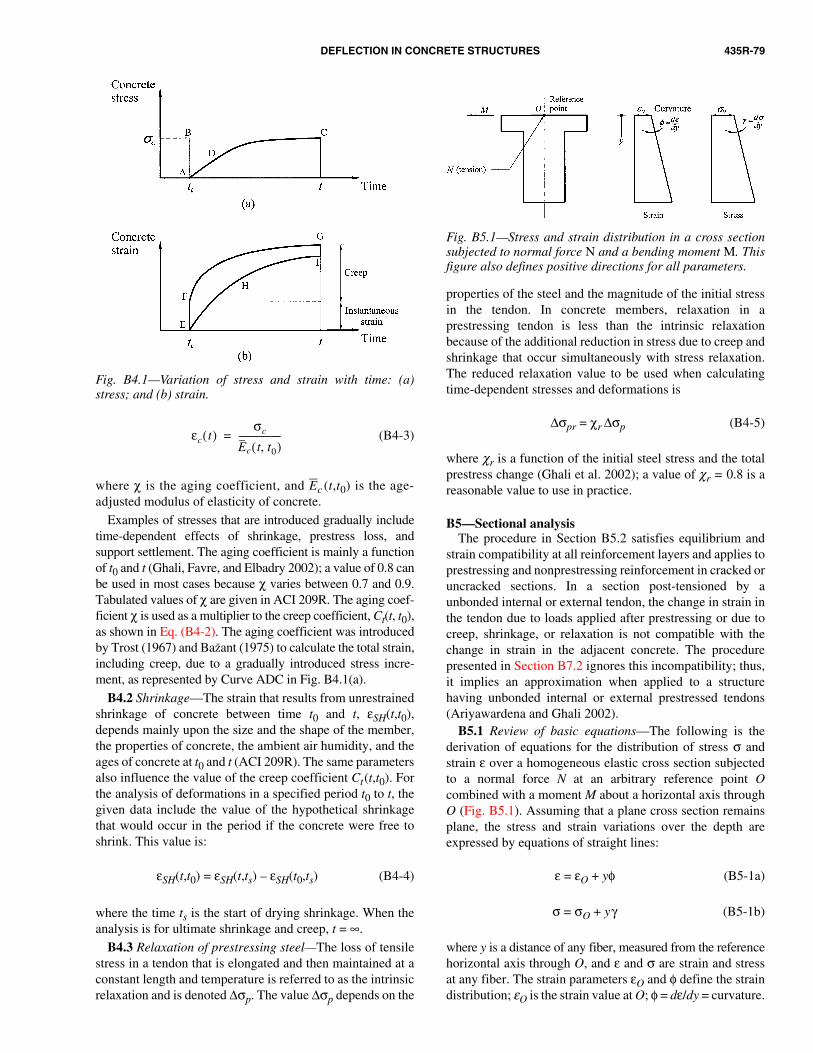
DEFLECTION IN CONCRETE STRUCTURES 435R-79
Fig. B4.1—Variation of stress and strain with time: (a)stress; and (b) strain.
(B4-3)
where χ is the aging coefficient, and Ec (t,t0) is the age-adjusted modulus of elasticity of concrete.
Examples of stresses that are introduced gradually includetime-dependent effects of shrinkage, prestress loss, andsupport settlement. The aging coefficient is mainly a functionof t0 and t (Ghali, Favre, and Elbadry 2002); a value of 0.8 canbe used in most cases because χ varies between 0.7 and 0.9.Tabulated values of χ are given in ACI 209R. The aging coef-ficient χ is used as a multiplier to the creep coefficient, Ct(t, t0),as shown in Eq. (B4-2). The aging coefficient was introducedby Trost (1967) and Bažant (1975) to calculate the total strain,including creep, due to a gradually introduced stress incre-ment, as represented by Curve ADC in Fig. B4.1(a).
B4.2 Shrinkage—The strain that results from unrestrainedshrinkage of concrete between time t0 and t, εSH(t,t0),depends mainly upon the size and the shape of the member,the properties of concrete, the ambient air humidity, and theages of concrete at t0 and t (ACI 209R). The same parametersalso influence the value of the creep coefficient Ct(t,t0). Forthe analysis of deformations in a specified period t0 to t, thegiven data include the value of the hypothetical shrinkagethat would occur in the period if the concrete were free toshrink. This value is:
εSH(t,t0) = εSH(t,ts) – εSH(t0,ts) (B4-4)
where the time ts is the start of drying shrinkage. When theanalysis is for ultimate shrinkage and creep, t = ∞.
B4.3 Relaxation of prestressing steel—The loss of tensilestress in a tendon that is elongated and then maintained at aconstant length and temperature is referred to as the intrinsicrelaxation and is denoted ∆σp. The value ∆σp depends on the
εc t( )σc
Ec t t0,( )-------------------=
properties of the steel and the magnitude of the initial stressin the tendon. In concrete members, relaxation in aprestressing tendon is less than the intrinsic relaxationbecause of the additional reduction in stress due to creep andshrinkage that occur simultaneously with stress relaxation.The reduced relaxation value to be used when calculatingtime-dependent stresses and deformations is
∆σpr = χr ∆σp (B4-5)
where χr is a function of the initial steel stress and the totalprestress change (Ghali et al. 2002); a value of χr = 0.8 is areasonable value to use in practice.
B5—Sectional analysisThe procedure in Section B5.2 satisfies equilibrium and
strain compatibility at all reinforcement layers and applies toprestressing and nonprestressing reinforcement in cracked oruncracked sections. In a section post-tensioned by aunbonded internal or external tendon, the change in strain inthe tendon due to loads applied after prestressing or due tocreep, shrinkage, or relaxation is not compatible with thechange in strain in the adjacent concrete. The procedurepresented in Section B7.2 ignores this incompatibility; thus,
Fig. B5.1—Stress and strain distribution in a cross sectionsubjected to normal force N and a bending moment M. Thisfigure also defines positive directions for all parameters.
it implies an approximation when applied to a structurehaving unbonded internal or external prestressed tendons(Ariyawardena and Ghali 2002).
B5.1 Review of basic equations—The following is thederivation of equations for the distribution of stress σ andstrain ε over a homogeneous elastic cross section subjectedto a normal force N at an arbitrary reference point Ocombined with a moment M about a horizontal axis throughO (Fig. B5.1). Assuming that a plane cross section remains
plane, the stress and strain variations over the depth areexpressed by equations of straight lines:ε = εO + yφ (B5-1a)
σ = σO + yγ (B5-1b)
where y is a distance of any fiber, measured from the referencehorizontal axis through O, and ε and σ are strain and stressat any fiber. The strain parameters εO and φ define the straindistribution; εO is the strain value at O; φ = dε/dy = curvature.

435R-80 ACI COMMITTEE REPORT
B5.2 Instantaneous and time-dependent stress andstrain—This section describes a procedure to analyze imme-diate increments of strains ε(t0) and stresses σ(t0) in aprestressed or nonprestressed section and the changes inthese values in a period t0 to t. The times t0 and t representinstances in multistage construction when a load orprestressing is applied, or when the support conditions aremodified. The term immediate means initial before occur-rence of creep, shrinkage, and relaxation.
The given data are as follows (Fig. B5.2):
Similarly, the stress parameters σO and γ define the stressdistribution; σO is stress value at O; γ = dσ/dy is the slope ofthe stress diagram. Assuming a linear stress-strain relation-ship, the strain and the stress parameters are related by
σO = EεO (B5-2a)
γ = Eφ (B5-2b)
where E is the modulus of elasticity of the homogeneousmaterial.
The stress resultants are:
N = (B5-3a)
M = (B5-3b)
Substitution of Eq. (B5-1a) and (B5-1b) into (B5-3a) and(B5-3b), respectively, gives the stress resultants
N = AσO + Bγ (B5-4a)
M = BσO + Iγ (B5-4b)
where A, B, and I are the cross-sectional area and its first andsecond moments about a horizontal axis through O, respec-tively. Thus,
A = dA; B = ydA; I = y2dA.
When N and M are known, the corresponding strain andstress parameters can be determined by solution of Eq. (B5-4a)and (B5-4b) and by using Eq. (5-2a) and (5-2b):
σO = (B5-5a)
(B5-5b)
(B5-6a)
(B5-6b)
When O is chosen at the centroid, B = 0, and Eq. (B5-5a),(B5-5b), (B5-6a), and (B5-6b) take the more familiar forms
(B5-7a)
σ Ad∫
σy Ad∫
∫ ∫ ∫
IN BM–
AI B2–---------------------
γ BN– AM+
AI B2–
---------------------------=
εOIN BM–
E AI B2–( )--------------------------=
φ BN– AM+
E AI B2–( )---------------------------=
σONA----=
(B5-7b)
(B5-8a)
(B5-8b)
Choosing O at a fixed point (for example, the top fiber)rather than the centroid has the advantage that the location ofthe centroid does not have to be determined for theuncracked and cracked stages. The equations in this sectionwill be used for the structural concrete section, with A, B, andI being properties of the transformed section, which is thearea of the concrete plus the area of the reinforcement multi-plied by the modular ratio (Ens or Eps for reinforcementdivided by Ec or Ec for concrete); where Ens and Eps are themoduli of elasticity of nonprestressing and prestressing rein-forcement, respectively; and Ec and Ec are modulus and age-adjusted modulus of concrete, respectively. The transformedsection has modulus of elasticity equal to that of concrete.When cracking occurs, only the area of concrete in compres-sion is included in the transformed section.
γ MI-----=
εON
EA-------=
φ MEI------=
• Gross concrete dimensions of the section, areas Aps andAns (with subscripts ps and ns referring to prestressingand nonprestressing reinforcement, respectively);
• Coordinates y defining the location of each area;• Magnitudes of normal force N and bending moment M
introduced at t0;• Elasticity moduli Ec(t0), Eps , and Ens;• Creep and aging coefficients of concrete Ct(t,t0) and
χ(t,t0), respectively; and• Unrestrained shrinkage of concrete εSH(t,t0), and
reduced relaxation ∆σpr.The values of N and M, respectively, represent the total
normal force at the reference point O, and the bendingmoment introduced at t0 including any statically indeterminateeffects of loads and prestressing. It is assumed that justbefore introducing N and M, the section is subjected to linearlyvarying strain and stress defined by the values at O and thederivatives with respect to y.
As an example, consider the cross section at the midspanof the post-tensioned, simple beam subjected at time t0 to aprestressing force P, and the member self-weight per unitlength q in Fig. B5.3(a) illustrates the meaning of the

DEFLECTION IN CONCRETE STRUCTURES 435R-81
Fig. B5.2—Analysis of instantaneous and time-dependentstrain and stress in a cross section for a single time intervalin a multistage construction.
Fig. B5.3—Examples explaining the meaning of symbols Nand M, Eq. (5-9a) and (5-9b): (a) post-tensioned simplebeam; (b) pretensioned simple beam; and (c) continuouspost-tensioned beam.
symbols N and M. The values of N and M introduced atmidspan section at t0 are
N = –P (B5-9a)
M = –ypsP + (B5-9b)
where P is the absolute value of the jacking prestress forceless friction loss; and yps and l are defined in Fig. B5.3(a).The parameters N and M are resultants of the instantaneousstress change in concrete, excluding the cross-sectional areaof the prestressing duct, and in the nonprestressing steel.
If the beam is pretensioned (Fig. B5.3(b)), Eq. (B5-9a) and(B5-9b) give values of N and M, but with P being the absolutevalue of the force in the tendon at t0, immediately before theprestress transfer. Furthermore, N and M represent resultantsof stress changes at transfer in the concrete and in thenonprestressing and the prestressing steels.
ql2
8-------
If the beam is continuous over two symmetrical spans(Fig. B5.3(c)), the values of N and M introduced at midspanat t0 are
N = –P (B5-10a)
M = –ypsP + (B5-10b)
where M is the statically indeterminate moment due toprestressing. N and M are resultants, at t0, of the stresschange in concrete and nonprestressing steel.
The analysis, which assumes cracking does not occur, isperformed in four steps. Figure B5.2 indicates additionalanalysis required to account for cracking, as discussed inSection B6.
ql2
8------- M+
Step 1—Calculate the instantaneous strain parameters,∆εO(t0) and ∆φ(t0), using Eq. (B5-6a) and (B5-6b) andsubstituting for A, B, and I the properties of a transformedsection composed of Ac plus nns(t0)Ans and nps(t0)Aps, wherenns or nps is the ratio of modulus of elasticity of nonpre-stressing Ens or prestressing Eps, reinforcement divided byEc(t0); Aps includes only the cross-sectional area of rein-forcement prestressed earlier than t0. The instantaneouschanges in stress parameters ∆σO(t0) and ∆γ(t0) are calcu-lated by Eq. (B5-2a) and (B5-2b), substituting Ec(t0) for E.

435R-82 ACI COMMITTEE REPORT
B5.3 Commentary on the general procedure and on aspecial case (nonprestressed sections subjected to M withoutN)—The general procedure gives the two parameters εO, φdefining the strain distribution in an uncracked prestressed ornonprestressed section subjected to N and M. When crackingoccurs, an additional step is required; refer to Section B6.Calculation of displacement in a plane frame from the strainparameters is a classical geometry problem that can besolved more easily by virtual work or other methods. Trans-verse deflection in beams can be determined from the curva-ture φ only (without the need for εO). The equationspresented below, which are derived from the general proce-dure in Section B5.2, give the immediate and the long-termcurvatures at nonprestressed reinforced concrete sectionssubjected to bending moment M.
Fig. B5.4—Properties of the transformed section at t0 and the age-adjusted trans-formed section: (a) cracked section at t0; and (b) age-adjusted transformed section.
Step 2—Determine parameters for the hypothetical strainchange that would occur, in the period t0 to t, if creep andshrinkage were unrestrained, using:
∆εO free(t,t0) = εSH(t,t0) + Ct∆εO(t,t0) (B5-11a)
∆φ free = Ct(t,t0)∆φ(t0) (B5-11b)
If the initial stress is not zero, creep due to stresses intro-duced earlier than t0 should be added, and the creep coefficientsshould be included in the input. ACI 209R, Ghali, Favre, andElbadry (2002), and CEB-FIP (1990) give guidance on creep-coefficient values.
Step 3—Calculate the two parameters defining the distri-bution of a hypothetical stress gradually introduced betweent0 and t to prevent the strain change calculated in Step 2,using Eq. (B5-2a) and (B5-2b).
σOrestraint = –Ec∆εO free (B5-12a)
γ restraint = –Ec∆φfree (B5-12b)
where Ec is the age-adjusted modulus of elasticity of concrete.
Ec(t, t0) = Ec(t0)/[1 + χCt(t, t0)] (B5-13)
Step 4—Calculate A, B, and I for concrete alone, withoutreinforcement, and substitute these values together withσO restraint and γ restraint in Eq. (B5-4a) and (B5-4b) to obtainthe resultants of stress required to prevent creep andshrinkage deformations
∆Ncreep, shrinkage = AconcreteσO restraint + (B5-14a)
Bconcreteγ restraint
∆Mcreep, shrinkage = BconcreteσO restraint + (B5-14b)
Iconcreteγrestraint
Determine the stress resultants that cancel the effect of theprestressing steel relaxation
∆Nrelax = Aps∆σpr (B5-15a)
∆Mrelax = Apsyps∆σpr (B5-15b)
The sum of the two normal forces and the two bendingmoments calculated in this step (Eq. (B5-14) and (B5-15))represent fictitious forces ∆N and ∆M, which would preventdeformations due to creep, shrinkage, and relaxation.
Eliminate the fictitious restraint by application of –∆N and–∆M on the age-adjusted transformed section (whose propertiesare A, B, and I). The age-adjusted transformed section iscomposed of Ac, nns Ans and npsAps; where nns or nps is themodulus of elasticity of reinforcement divided by Ec(t,t0).Calculate the changes in strain and stress parameters (changesin εO, φ, σO, γ) by substitution of –∆N, –∆M, Ec(t,t0), A, B,and I in Eq. (B5-5a), (B5-5b), (B5-6a), and (B5-6b).
Update the initial stress parameters by adding the stressparameters determined in Steps 1, 3, and 4. Update the initialstrain parameters by adding the strain parameters determinedin Steps 1 and 4.
Consider a nonprestressed reinforced concrete crosssection (Fig. B5.4) subjected at time t0 to a bending momentM, without normal force. The general procedure of analysisin Section B5.2 reduces to Eq. (B11-1) to (B11-3) for initial

DEFLECTION IN CONCRETE STRUCTURES 435R-83
Section B7—Tension-stiffeningThe normal strain εO2 and the curvature φ2 calculated for
a cracked section represent the state at a crack location.Away from the crack location, concrete bonded to the rein-forcement tends to restrain deformations and reduce thenormal strain and the curvature. This is called tension-stiff-ening. Empirical approaches have been proposed to accountfor the tension stiffening effect on the displacements. Theseprocedures use the mean values of strain parameters εOm andφm to calculate displacements. The mean parameters have
B6—Calculation when cracking occursIf at the end of Step 1 of the general procedure it is deter-
mined that cracking occurs (the extreme fiber stress exceedsthe tensile strength of concrete), the calculations indicated inFig. B5.2 become necessary. Partition M and N into twoparts, such that M = M1 + M2 and N = N1 + N2. The pair N1and M1 (decompression forces, a part of the pair M and N)represents the stress resultants that will bring to zero theconcrete stresses existing before the introduction of M andN; the pair N2 and M2 represents the remainder. With N1 andM1, the section is uncracked. Cracking is produced only byN2 combined with M2. For the analysis, two loading stagesneed to be considered: 1) N1 and M1 applied on an uncrackedsection; and 2) N2 and M2 applied on a cracked section, inwhich the concrete outside the compression zone is ignored.The strains in the two stages are added to give the totalinstantaneous change. The values of N1 and M1 can be calcu-lated by Eq. (B5-4a) and (B5-4b), substituting for σ and γ,the initial stress parameters with reversed sign and for A, B,and I properties of the uncracked transformed section. AfterN1 and M1 have been determined, N2 and M2 are calculatedby N2 = N – N1 and M2 = M – M1.
Performing Steps 2, 3, and 4 for the cracked section givesthe time-dependent changes in strain and stress. Numericalexamples and a computer program based on the detailedmethod of analysis presented previously can be found inSection B10 and in Ghali, Favre, and Elbadry (2002); a
curvature φ(t0) and the curvature changes (∆φ)creep and(∆φ)shrinkage due to creep and shrinkage occurring betweent0 and t. The long-term curvature at time t is the sum of thecurvatures determined by the three equations
φ(t0) = (B5-16)
(∆φ)creep = φ(t0)Ctκcreep (B5-17)
(∆φ)shrinkage = κshrinkage (B5-18)
where φc is the instantaneous curvature at an uncrackedhomogenous concrete section (without reinforcement)
φc = (B5-19)
whereEc(t0) = the modulus of elasticity of concrete at time t0;Ct and εSH = the creep coefficient and the unrestrained
shrinkage of concrete in the period t0 to t,respectively;
d = the distance from extreme compression fiberto the centroid of the tension reinforcement;
Ig = moment of inertia of the gross concretesection about its centroidal axis, neglectingreinforcement; and
κcreep and κshrinkage = dimensionless coefficients dependingon properties of the section.
κcreep = (B5-20)
κshrinkage = (B5-21)
whereI = the moment of inertia about the centroidal axis of
the transformed section composed of concretearea Ac plus n[= Es /Ec(t0)] multiplied by the areaof reinforcement;
I = moment of inertia about the centroidal axis of theage-adjusted transformed section composed ofconcrete area Ac plus n(= Es/Ec) multiplied by areasof reinforcements;
Ic = moment of inertia of the concrete area Ac about thecentroidal axis of the age-adjusted transformedsection;
Ec = the age-adjusted modulus of elasticity of concrete(Eq. (B5-13));
∆y = the y-coordinate of the centroid of the age-adjustedtransformed section, measured downward from the
Ig
I----φc
εcs
d------–
MEc t0( )Ig
-------------------
Ic Acyc∆y+
I----------------------------
Acycd
I--------------
neutral axis at t0 (the centroidal axis of the trans-formed section at t0); and
yc = the y-coordinate of the centroid of Ac , measureddownward from the centroid of the age-adjustedtransformed section.
In most cases, the tension steel area As near the bottomfiber is larger than the compression steel area As′ and thevalues of ∆y and yc are positive and negative, respectively(Fig. B5.4(a) and (b)).
The symbol Ac means the active area of concrete at time t0.Thus, when the previous equations are used for a crackedsection, Ac is the area of concrete within the compression zoneat time t0. Derivation of the equations in this Appendix fromthe general procedure in Section B5.2 and graphs for the coef-ficients κcreep and κshrinkage are available (Ghali, Favre, andElbadry 2002).
computer program can be used to perform the analysis(Ghali and Elbadry 1986 and 2001).

435R-84 ACI COMMITTEE REPORT
B8—Deflection and change in length of a frame memberThe following equation can be used to calculate the trans-
verse deflection δcenter at midlength of a straight member ofa frame
(B8-1)
where
l = the member length; and
φm1, φm2, and φm3 = mean curvatures at one end, at the cen-ter, and at the other end, respectively.
Similarly, the rotation at member ends θend and thechange in member length ∆l can be determined by:
and (B8-2)
(B8-3)
where εOm1, εOm2, and εOm3 are mean normal strains at oneend, at the center, and at the other end, respectively.
The deflection δcenter and the rotation θend are measuredfrom the chord, which is the straight line joining the two ends.
Equations (B8-1) to (B8-3) assume parabolic or straightline variations of φm and εOm over the length of a framemember. The method of virtual work (Ghali and Neville1997) gives the translation in any direction and the rotationat any section of a frame having any variation of φm and εOm.Equations (B8-4) to (B8-6), which are derived by virtual
δcenterl
2
96------ φm1 10φm2 φm3+ +( )=
θend1l
6--- φm1 2φm2+( )=
θend2l
6--- 2φm2 φm3+( )=
∆ll
6--- εOm1 4εOm2 εOm3+ +( )=
B7.2 CEB-FIP approach—For any prestressed or nonpre-stressed reinforced section, the mean strain parameters εOmand φm can be determined by interpolation betweenuncracked and cracked states
εOm = (1 – ζ)εO1 – ζεO2 (B7-2a)
φm = (1 – ζ)φ1 + ζφ2 (B7-2b)
whereεO1 and φ1 = strain parameters calculated using the
uncracked transformed section;εO2 and φ2 = strain parameters calculated using the
cracked transformed sectionζ = an empirical interpolation coefficient,
expressed by CEB-FIP Model Code MC-90 (1990) as follows:
ζ = 1 – β (when σ1 max > fct, cracked) (B7-3)
ζ = 0 (when σ1 max < fct , uncracked) (B7-4)
where fct = the tensile strength of concrete;σ1 max = calculated tensile stress at extreme fiber when
cracking is ignored; andβ = coefficient to account for the effects of bond
quality of reinforcement, cyclic loading, andsustained loading on tension stiffening.
In most cases, β = 0.5 can be used when deformed bars areemployed and cyclic or sustained loads are applied.
fct
σ1max
------------- 2
intermediate values between the strain parameters inuncracked and the cracked states.
B7.1 Branson’s effective moment of inertia—For amember subjected to bending moment without a normalforce, only the curvature φm is required to calculate trans-verse deflection. For a nonprestressed reinforced concretesection subjected to bending moment M without normalforce, Branson’s equations (Branson 1977) for mean curva-ture are:
(B7-1a)
(B-7-1b)
whereIe = the effective moment of inertia;Ig = the second moment of gross concrete area about its cen-
troidal axis, ignoring the presence of reinforcement;I2 = the second moment of area of the transformed
cracked section about its centroidal axis;Mcr = cracking moment; andM = the moment on the section.
φmM
EIe
--------=
IeMcr
M---------
4
Ig 1Mcr
M---------
4
– I2+=
B7.3 Other tension stiffening approaches—The completestress-strain curve for concrete in tension has been used bymany researchers to model the tension-stiffening effect(Gilbert and Warner 1978; Polak and Vecchio 1993; Scanlonand Murray 1974). This approach can be incorporated intothe section curvature procedure by appropriate modificationof the transformed-section properties. Introduction of thenonlinear stress-strain relationship would involve an itera-tive solution. Gilbert and Warner (1998) have modeled theeffect by increasing the effective stiffness of the reinforcingsteel, while Kaufmann and Marti (1998) have introduced atension-chord model based on assumed bond stress distribu-tion between cracks.
work, can be used instead of Eq. (B8-1) to (B8-3) with anyvariation of φm and εOm over the length of a frame member:
(B8-4)δcenter12--- φmx x l
2--- φm 1 x
l--–
xdl 2⁄
l
∫+d0
l 2⁄
∫=
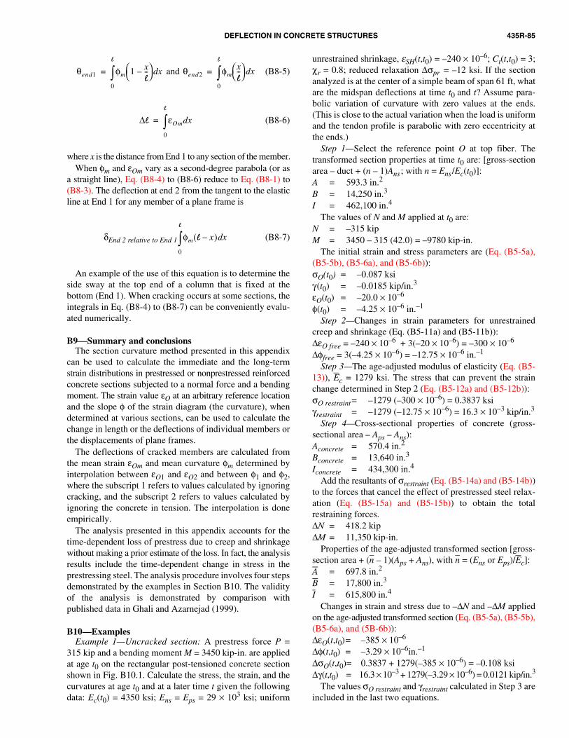
DEFLECTION IN CONCRETE STRUCTURES 435R-85
(B8-6)∆l εOm xd
0
l
∫=
B10—ExamplesExample 1—Uncracked section: A prestress force P =
315 kip and a bending moment M = 3450 kip-in. are appliedat age t0 on the rectangular post-tensioned concrete sectionshown in Fig. B10.1. Calculate the stress, the strain, and thecurvatures at age t0 and at a later time t given the followingdata: Ec(t0) = 4350 ksi; Ens = Eps = 29 × 103 ksi; uniform
and (B8-5)θend1 φm 1 xl--–
xd
0
l
∫= θend2 φmxl--
xd
0
l
∫=
where x is the distance from End 1 to any section of the member.When φm and εOm vary as a second-degree parabola (or as
a straight line), Eq. (B8-4) to (B8-6) reduce to Eq. (B8-1) to(B8-3). The deflection at end 2 from the tangent to the elasticline at End 1 for any member of a plane frame is
δEnd 2 relative to End 1 (B8-7)
An example of the use of this equation is to determine theside sway at the top end of a column that is fixed at thebottom (End 1). When cracking occurs at some sections, theintegrals in Eq. (B8-4) to (B8-7) can be conveniently evalu-ated numerically.
B9Summary and conclusionsThe section curvature method presented in this appendix
can be used to calculate the immediate and the long-termstrain distributions in prestressed or nonprestressed reinforcedconcrete sections subjected to a normal force and a bendingmoment. The strain value εO at an arbitrary reference locationand the slope φ of the strain diagram (the curvature), whendetermined at various sections, can be used to calculate thechange in length or the deflections of individual members orthe displacements of plane frames.
The deflections of cracked members are calculated fromthe mean strain εOm and mean curvature φm determined byinterpolation between εO1 and εO2 and between φ1 and φ2,where the subscript 1 refers to values calculated by ignoringcracking, and the subscript 2 refers to values calculated byignoring the concrete in tension. The interpolation is doneempirically.
The analysis presented in this appendix accounts for thetime-dependent loss of prestress due to creep and shrinkagewithout making a prior estimate of the loss. In fact, the analysisresults include the time-dependent change in stress in theprestressing steel. The analysis procedure involves four stepsdemonstrated by the examples in Section B10. The validityof the analysis is demonstrated by comparison withpublished data in Ghali and Azarnejad (1999).
φm l x–( ) xd
0
l
∫
unrestrained shrinkage, εSH(t,t0) = –240 × 10–6; Ct(t,t0) = 3;χr = 0.8; reduced relaxation ∆σpr = –12 ksi. If the sectionanalyzed is at the center of a simple beam of span 61 ft, whatare the midspan deflections at time t0 and t? Assume para-bolic variation of curvature with zero values at the ends.(This is close to the actual variation when the load is uniformand the tendon profile is parabolic with zero eccentricity atthe ends.)
Step 1—Select the reference point O at top fiber. Thetransformed section properties at time t0 are: [gross-sectionarea – duct + (n – 1)Ans; with n = Ens/Ec(t0)]:A = 593.3 in.2
B = 14,250 in.3
I = 462,100 in.4
The values of N and M applied at t0 are:N = –315 kipM = 3450 – 315 (42.0) = –9780 kip-in.
The initial strain and stress parameters are (Eq. (B5-5a),(B5-5b), (B5-6a), and (B5-6b)):σO(t0) = –0.087 ksiγ(t0) = –0.0185 kip/in.3
εO(t0) = –20.0 × 10⁻⁶
φ(t0) = –4.25 × 10⁻⁶ in.–1
Step 2—Changes in strain parameters for unrestrainedcreep and shrinkage (Eq. (B5-11a) and (B5-11b)):∆εO free = –240 × 10–6 + 3(–20 × 10–6) = –300 × 10–6
∆φfree = 3(–4.25 × 10⁻⁶) = –12.75 × 10⁻⁶ in.–1
Step 3—The age-adjusted modulus of elasticity (Eq. (B5-13)), Ec = 1279 ksi. The stress that can prevent the strainchange determined in Step 2 (Eq. (B5-12a) and (B5-12b)):σO restraint= –1279 (–300 × 10–6) = 0.3837 ksiγrestraint = –1279 (–12.75 × 10⁻⁶) = 16.3 × 10⁻³ kip/in.3
Step 4—Cross-sectional properties of concrete (gross-sectional area – Aps – Ans):Aconcrete = 570.4 in.2
Bconcrete = 13,640 in.3
Iconcrete = 434,300 in.4
Add the resultants of σrestraint (Eq. (B5-14a) and (B5-14b))to the forces that cancel the effect of prestressed steel relax-ation (Eq. (B5-15a) and (B5-15b)) to obtain the totalrestraining forces. ∆N = 418.2 kip∆M = 11,350 kip-in.
Properties of the age-adjusted transformed section [gross-section area + (n – 1)(Aps + Ans), with n = (Ens or Eps)/Ec]:A = 697.8 in.2
B = 17,800 in.3
I = 615,800 in.4
Changes in strain and stress due to –∆N and –∆M appliedon the age-adjusted transformed section (Eq. (B5-5a), (B5-5b),(B5-6a), and (5B-6b)):∆εO(t,t0)= –385 × 10–6
∆φ(t,t0) = –3.29 × 10⁻⁶in.–1
∆σO(t,t0)= 0.3837 + 1279(–385 × 10–6) = –0.108 ksi∆γ(t,t0) = 16.3 × 10⁻³ + 1279(–3.29 × 10⁻⁶) = 0.0121 kip/in.3
The values σO restraint and γrestraint calculated in Step 3 areincluded in the last two equations.

435R-86 ACI COMMITTEE REPORT
The strain and stress parameters at time t (add the valuesdetermined in this step and in Step 1):εO(t) = (–20 – 385)10–6 = –405 × 10–6
φ(t) = (–4.25 – 3.29)10–6 = –7.53 × 10⁻⁶ in.–1
σO(t) = –0.087 – 0.108 = –0.195 ksiγ(t) = –0.0185 + 0.0121 = –0.00641 kip/m3
Deflection: The immediate and the long-term deflection atthe center of span (Eq. (B8-5)):
–0.24 in.
–0.42 in.
The curvatures at the two ends are ignored for simplicity ofpresentation. If these curvatures are calculated and Eq. (B8-5)is used, δcenter(t) would be –0.40 in. The minus sign meansupward deflections.
Several parameters given as input are dependent upon t0and t. As mentioned earlier, in practice the analysis should bepreceded by selecting the appropriate values of the parame-ters (ACI 209R; CEB-FIP [1990]; and Magura, Sozen, andSiess [1964]).
Example 2—Cracked Section: For the section of Example 1(Fig. B10.1), determine the axial strain and the curvature attime t immediately after application of an additional bendingmoment M = 6000 kip-in. (for example, caused by live load).Assume that at time t, the modulus of elasticity of concreteEc(t) = 4600 ksi and fct = 0.36 ksi.
The properties of the transformed uncracked section attime t [gross-sectional area + (n – 1) (Ans + Aps); with n =(Ens or Eps)/Ec(t)]:A1 = 605.8 in.2
B1 = 14,800 in.3
I1 = 484,800 in.4
δcenter t0( ) 61 12×( )2
96------------------------- 10 4.25 10× 6––( )[ ]= =
δcenter t( ) 61 12×( )2
96------------------------- 10 7.53 10× 6––( )[ ]= =
Fig. B10.1—Beam cross section of Examples 1 and 2.
The immediate changes in strain parameters assuming nocracking (Eq. (B5-6a) and (B5-6b)):∆εO1 = –258 × 10–6
∆φ1 = 10.57 × 10⁻⁶ in.-1
Change in stress at the bottom fiber = 1.146 ksiStress at the bottom fiber just before live load application(determined by substituting σO(t) and γ (t) calculated inExample 1 in Eq. (B5-1), with y = 48 in.) = –0.502 ksiUpdated stress at bottom fiber at time t = σ1 max = 0.644 ksi
This stress is greater than fct , which indicates that crackingoccurs. Substituting A1, B1, and I1 and the values of –σO(t)and –γ(t) determined in Example 1 in Eq. (B5-4) gives thedecompression forces:N1 = 212.7 kipN2 = –212.7 kipM1 = 5983 kip-in.M2 = 6000 – 5983 = 17 kip-in.
Substitution of A1, B1, I1, N1, and M1 in Eq. (B5-6a) and(B5-6b) gives the immediate changes in strain parameters inthe decompression stage:∆εO1= 42 × 10–6
∆φ1 = 1.39 × 10⁻⁶ in.–1
With N2 and M2 applied on a reinforced concrete crackedsection, determine the depth of the compression zone; c =22.9 in. Determination of c is a standard analysis discussedin many books, including Ghali, Favre, and Elbadry (2002).Properties of the cracked section, ignoring concrete intension are:A2 = 308.1 in.2
B2 = 4288 in.3
I2 = 98,240 in.4
Substituting A2, B2, I2, N2, and M2 in Eq. (B5-6a) and (B5-6b) gives the immediate changes in strain parameters, withthe concrete in tension ignored:∆εO2 = –383 × 10–6
∆φ2 = 16.77 × 10⁻⁶ in.–1
The interpolation coefficient (Eq. (B7-3)):
The mean strain parameters (Eq. (B7-2)):∆εOm = (1 – 0.844)(–258)10–6 + 0.844(42 – 383)10–6 =
– 328 × 10–6
∆φm = (1 – 0.844)(10.57)10–6 + 0.844(1.39 + 16.77)10–6 =16.97 × 10⁻⁶
The updated curvature and deflection at center of span,immediately after live load application:
Curvature after live load application = (–7.53 + 16.97) 10–6 =9.44 × 10⁻⁶ in.–1; and
Deflection after live load application (Eq. B8-5) =
= 0.53 in.
ζ 1 0.5 0.3600.644-------------
2– 0.844= =
61 12×( )2
96------------------------- 10 9.44 10 6–×( )[ ]

DEFLECTION IN CONCRETE STRUCTURES 435R-87
Fig. B10.2—Example section subjected to moment: (a) cracked section at age t0 (neutralaxis through centroid of transformed section); and (b) properties of age-adjusted trans-formed section.
Example 3Nonprestressed section in flexure: Determinethe curvature φ(t0) and φ(t) for a rectangular cracked sectionshown in Fig. B10.2. Given data:Ec(t0) = 3625 ksi (25.00 GPa)Es = 29,000 ksi (200 GPa)Ct = 2.0Ec = 1390 ksi (9.59 GPa)εSH = –300 × 10–6
M = 6000 kip-in. (452 kN-m)n = Es/Ec(t0) = 8.00n = Es/Ec = 20.86Ig = 64,000 in.4
Depth of compression zone for a rectangular section(Fig. B10.2a) is:
wherea1 = b/2a2 = nAs + (n –1) As′a3 = –nAsd – (n – 1)As′ds′ This gives:a1 = 6 in.a2 = 48.75 in.2
a3 = –1475 in.3
c = 12.13 in.The centroid of the transformed section at t0 coincides
with the bottom edge of the compression zone. Othergeometrical properties of the section are:I = 30,510 in.4
Ac = 144.4 in.2
The centroid of the age-adjusted transformed section is at:∆y = 5.11 in.I = 61,020 in.4
yc = –11.16 in.Ic = 19,670 in.4
ca2– a2
2 4a1a3–+
2a1
----------------------------------------------=
Equations (B5-17) to (B5-21) give:
in.–1
The initial curvature at time t0:
in.–1
(∆φ)creep = 54.25 × 10⁻⁶(2.00)(0.189) = 20.51 × 10⁻⁶ in.–1
(∆φ)shrinkage = (0.950) = 7.92 × 10⁻⁶ in.–1
The long-time curvature at time t:
φ(t) = (54.25 + 20.51 + 7.92) × 10–6 = 82.7 × 10⁻⁶ in.–1
B11—ReferencesB11.1 Referenced standards and reports—The following
standards and reports listed were the latest editions at thetime this document was prepared. Because these documentsare revised frequently, the reader is advised to contact thesponsoring group to refer to the latest version.
American Concrete Institute209R Prediction of Creep, Shrinkage, and Tempera-
ture Effects in Concrete Structures318/318R Building Code Requirements for Structural
Concrete and Commentary
κcreep19 760 144.4 11.16–( ) 5.11( )+,
61 020,--------------------------------------------------------------------------- 0.189= =
κshrinkage144.4 11.16–( ) 36( )
61 020,---------------------------------------------- 0.950= =
φc6000
3625 64 000,( )----------------------------------- 26.86 10 6–×= =
φ t0( ) 64 000,30 509,------------------ 25.86 10 6–×( ) 54.25 10 6–×–=
300 10 6–×–( )36
---------------------------------

435R-88 ACI COMMITTEE REPORT
These publications may be obtained from:
American Concrete InstituteP.O. Box 9094Farmington Hills, MI 48333-9094
B11.2 Cited references—Ariyawardena, N., and Ghali, A., 2002, “Prestressing with
Unbonded or External Tendons: Analysis and ComputerModel,” Journal of Structural Engineering, ASCE, V. 128,No. 12, pp. 1493-1501.
Bažant, Z. P., 1975, “Prediction of Concrete Creep EffectsUsing Age-Adjusted Effective Modulus Method,” ACIJOURNAL, Proceedings V. 69, No. 4, Apr., pp. 212-217.
Branson, D. E., 1977, Deformation of Concrete Structures,McGraw-Hill, New York, 546 pp.
CEB-FIB, 1990, Model Code for Concrete Structures,CEB, Thomas Telford, London.
Ghali, A., and Azarnejad, A., 1999, “Deflection Predictionof Members of Any Concrete Strength,” ACI StructuralJournal, V. 96, No. 5, Sept.-Oct., pp. 807-816.
Ghali, A., and Elbadry, M., 1986 and 2000, User’s Manualand Computer Program CRACK, Research Report CE85-1,Department of Civil Engineering, University of Calgary,Calgary, Alberta, Canada, Feb. Updated and renamedversion: “Reinforced and Prestressed Members, Computerprogram RPM,” American Concrete Institute, software code076AG2.CP.
Ghali, A.; Favre, R.; and Elbadry, M., 2002, ConcreteStructures: Stresses and Deformations, 3rd Edition, Spon
Press, London and New York, website: www.sponpress.com/concretestructures.
Ghali, A., and Neville, A. M., 2003, Structural Analysis: AUnified Classical and Matrix Approach, 5th Edition, SponPress, London and New York, 844 pp.
Gilbert, R. I., and Warner, R. F., 1978, “Tension Stiffeningin Reinforced Concrete Slabs,” Journal of the StructuralDivision, V. 104, No. ST.
Hall, T. S., and Ghali, A., 1997, “Prediction of the FlexuralBehavior of Concrete Members Reinforced with GFRPBars,” Society for the Advancement of Material and ProcessEngineering, V. 42, pp. 298-310.
ISIS Canada, 2001, “Reinforcing New Structures withFiber Reinforced Polymers,” Design Manual No. 3.
Kaufmann, W., and Marti, P., 1998, “StructuralConcrete: Cracked Membrane Model,” Journal of Struc-tural Engineering, V. 124, No. 12, pp. 1467-1475.
Magura, D.; Sozen, M. A.; and Siess, C. P., 1964, “AStudy of Stress Relaxation in Prestressing Reinforcement,”PCI Journal, V. 9, No. 2, pp. 13-57.
Polak, M. A., and Vecchio, F. J., 1993, “Nonlinear Analysisof Reinforced Concrete Shells,” Journal of StructuralEngineering, V. 119, No. 12, pp. 3439-3462.
Scanlon, A., and Murray, D. W., 1974, “Time DependentReinforced Concrete Slab Deflections,” Journal of theStructural Division, V. 100, No. ST9, pp. 1911-1924.
Trost, H., 1967, “Auswirkungen des Superpositionsprinzipsauf Kriech-und Relaxations—Probleme bei Beton und Spann-beton,” Beton-und Stahlbetonbau, V. 62, No. 10, pp. 230-238.
ACI Committee 435 during creation of Appendix B
Andrew Scanlon*
ChairDebrethann R. Cagley-Orsak
Secretary
John H. Allen N. John Gardner* Vilas S. Mujumdar
Alex Aswad Amin Ghali* Hani H. A. Nassif
Abdeldjelil Belarbi S. K. Ghosh Edward G. Nawy
Brahim Benmokrane Anand B. Gogate Maria A. Polak*
Donald R. Buettner Hidayat N. Grouni Madhwesh Raghavendrachar
Finley A. Charney Robert W. Hamilton B. Vijaya Rangan
Ramesh M. Desai Paul C. Hoffman Charles G. Salmon
Luis Garcia Dutari Cheng-Tzu T. Hsu Mark P. Sarkisian
Mamdouh M. El-Badry* Shivaprasad Kudlapur Richard H. Scott
A. Samer Ezeldin Peter Lenkei A. Fattah Shaikh
Russell S. Fling Faris A. Malhas Himat T. Solanki
Simon H. C. Foo Bernard L. Meyers Susanto Teng
*Members who prepared Appendix B.

DEFLECTION IN CONCRETE STRUCTURES 435R-77
CONVERSION FACTORS---INCH-POUND TO SI (METRIC)*
To convert from toLength
multiply by
inch . . . . . . . . . . . . . . . . . . . . . . . . . . . . . . . . . . . . . . . millimeter (mm) . . . . . . . . . . . . . . . . . . . . . . . . . . . . . . . . . .foot
25.4Et. . . . . . . . . . . . . . . . . . . . . . . . . . . . . . . . . . . . . . . . .
yardmeter (m) . . . . . . . . . . . . . . . . . . . . . . . . . . . . . . . . . . . . . 0.3048E
. . . . . . . . . . . . . . . . . . . . . . . . . . . . . . . . . . . . . . . . .mile (statute)
meter (m) . . . . . . . . . . . . . . . . . . . . . . . . . . . . . . . . . . . . . 0.9144E.................................kilometer (km) ................................... 1.609
Area
square inch .............................. square millimeter (mm2) .............................. 645.1square foot ................................ square meter (m2) . . . . . . . . . . . . . . . . . . . . . . . . . . . . . . . . . . 0.0929square yard ................................ square meter (m’) .................................. 0.8361
Volume (capacity)
ounce . . . . . . . . . . . . . . . . . . . . . . . . . . . . . . . . . . 29.57gallon
. . . . . . . . . . . . . . . . . . . . . . . . . . . . . . . . . . . . ..milltiiters(m L3).................................... cubic meter (m ).................................. 0.003785
cubic inch ............................... cubic millimeter (mm3) ............................. 16390cubic foot ..................................cubic yard
cubic meter (m3) ................................... 0.02832................................. cubic meter (m3)$ .................................. 0.7646
Force
kilogram-force ................................. newton (N) ..................................... 9.807kip-force ...................................kilo newton (kN) ................................... 4.448pound-force . . . . . . . . . . . . . . . . . . . . . . . . . . . . . . . . . . . newton (N)) . . . . . . . . . . . . . . . . . . . . . . . . . . . . . . . . . . . . . 4.448
Pressure or stress (force per area)
kilogram-force/square meter. ...................... pascal (Pa) . . . . . . . . . . . . . . . . . . . . . . . . . . . . . . . . . . . . . 9.807kip-force/square inch (ksi) ..................... .................................. 6.895newton/square meter (N/m2)
megapascal (MPa)...................... pascal (Pa) ..................................... l.000E
pound-force/square foot .......................... pascal (Pa) .................................... 47.88pound-force/square inch (psi) .................... kilopascal (kPa )) . . . . . . . . . . . . . . . . . . . . . . . . . . . . . . . . . . . 6.895
Bending moment or torque
inch-pound-force ........................... newton-meter (Nqtr) ................................. 0.1130foot-pound-force ........................... newton-meter (N.m) ................................. 1.356meter-kilogram-force ........................ newton-meter (N.m) ................................. 9.807
Mass
ounce-mass (avoirdupois) .......................... gram (g) ..................................... 28.34pound-mass (avoirdupois) ....................... kilogram (kg) .................................... 0.4536ton (metric) ................................. megagram (mg) ................................... 1.000Eton (short, 2000 lbm) ........................... kilogram (kg) .................................. 907.2
Mass per volume
pound-mass/cubic foot .................... kilogram/cubic meter (ks/m3) ............................. 16.02pound-mass/cubic yard .................... kilogram/cubic meter (kg/m3) . . . . . . . . . . . . . . . . . . . . . . . . . . . . . . 0.5933pound-mass/gallon .. ....q ................ kilogram/cubic meter (kg/m3) . . . . . . . . . . . . . . . . . . . . . . . . . . . . 119.8
Temperature S S
degrees Fahrenheit (F) ....................... degrees Celsius (C) ...................... t, = (tF - 32)/1.8degrees Celsius (C) .........................degrees Fahrenheit (F) ..................... tF = 1.8t, + 32
*This selected list gives practical conversion factors of units found in concrete technology. The reference sources for information on SI units and more exactconversion factors are ASTM E 380 and E 621. Symbols of metric units are given in parenthesis.
t E Indicates that the factor given is exact.$ One liter (cubic decimeter) equals 0.001 m3or 1000 cm3.0 These equations convert one temperature reading to another and include the necessary scale corrections. To convert a difference in temperature from Fahrenheit
degrees to Celsius de- divide by 1.8 only. i.e., a change from 70 to 88 F represents a change of 18 F or 18/1.8 = 10 C deg.