4 Auto Under Frequency Load Shedding Tests - Transpower · 4 Auto Under Frequency Load Shedding...
10
1 Distributor Tests Distributors 4 Auto Under Frequency Load Shedding Tests 4.1.2 AUFLS Profiles and Trip Settings. 4.1.2.1 Content This section describes the tests that are required to confirm functionality and compliance of AUFLS. 4.1.2.2 Application This section applies to all asset owners who offer AUFLS and should be read along side the latest Technical Requirment Schedule (TRS). 4.1.2.3 Purpose of test AUFLS is a critical factor in the system operator’s assessment of reserve requirements to prevent cascade failure of the power system. Tests are required to meet obligations set out in the Technical Requirements Schedule, which include confirmation of: trip settings; reliability 1 of the AUFLS scheme; and end to end operation times. 4.1.2.4 Test outcomes The tests should: Provide high-speed test results to demonstrate the AUFLS relay functionality, as well as the guard, trigger and clearing time delays. where df/dt relays are used, demonstration of operation to the correct rate of change of frequency verify relay logic, DC control logic to confirm operation is in accordance with relay and instrumentation diagrams and operating notes 4.1.2.5 Compliance Report The information is required in a compliance report within 3 months of testing. 4.1.2.6 Tests that will achieve required outcome Appropriate tests can be found in the appendix (Guide for testing): 5.11 AUFLS 1 Reliability of a protection scheme is rated in two aspects, dependability and security. Dependability is defined as “the degree of certainty that a relay or relay system will operate correctly” (IEEE C37.2). Security “relates to the degree of certainty that a relay or relay system will not operate correctly” (IEEE C37.2).
-
Upload
nguyenquynh -
Category
Documents
-
view
226 -
download
0
Transcript of 4 Auto Under Frequency Load Shedding Tests - Transpower · 4 Auto Under Frequency Load Shedding...
1
Distributor Tests
Distributors
4 Auto Under Frequency Load Shedding Tests
4.1.2 AUFLS Profiles and Trip Settings.
4.1.2.1 Content This section describes the tests that are required to confirm functionality and compliance of AUFLS.
4.1.2.2 Application This section applies to all asset owners who offer AUFLS and should be read along side the latest Technical Requirment Schedule (TRS).
4.1.2.3 Purpose of test AUFLS is a critical factor in the system operator’s assessment of reserve requirements to prevent cascade failure of the power system.
Tests are required to meet obligations set out in the Technical Requirements Schedule, which include confirmation of:
trip settings; reliability
1 of the AUFLS scheme; and
end to end operation times.
4.1.2.4 Test outcomes The tests should:
Provide high-speed test results to demonstrate the AUFLS relay functionality, as well as the guard, trigger and clearing time delays.
where df/dt relays are used, demonstration of operation to the correct rate of change of frequency
verify relay logic, DC control logic to confirm operation is in accordance with relay and instrumentation diagrams and operating notes
4.1.2.5 Compliance Report
The information is required in a compliance report within 3 months of testing.
4.1.2.6 Tests that will achieve required outcome
Appropriate tests can be found in the appendix (Guide for testing):
5.11 AUFLS
1 Reliability of a protection scheme is rated in two aspects, dependability and security. Dependability is defined as “the
degree of certainty that a relay or relay system will operate correctly” (IEEE C37.2). Security “relates to the degree of certainty that a relay or relay system will not operate correctly” (IEEE C37.2).

2
Appendix A
Testing examples and theory
5 Guide for testing – Examples and theory
5.1 Overview
5.1.1 Purpose This section provides specific details of the methods for testing, and some examples of tests that asset owner’s may use as a basis for developing testing plans
Contents 5.1.1 ....... PURPOSE ..................................................................................................................................................... 2
5.11 AUFLS .................................................................................................................................................................. 3 5.11.1 ..... GENERAL REQUIREMENTS ............................................................................................................................. 3 5.11.2 ..... EXAMPLE RELAY AND INSTRUMENT DIAGRAM .................................................................................................. 3 5.11.3 ..... EXAMPLE DC CONTROL AND RELAY LOGIC DIAGRAM ....................................................................................... 4 5.11.4 ..... EXAMPLE SETTINGS AND TRIP EQUATIONS ...................................................................................................... 6 5.11.5 ..... CONFORMANCE TESTS .................................................................................................................................. 7 5.11.6 ..... GRAPHICAL REPRESENTATION OF TESTS ........................................................................................................ 9

3
Appendix A
Testing examples and theory
5.11 AUFLS
5.11.1 General Requirements
Item Description
Tests Relay characteristics required by TRS should all be tested by secondary injection using a test set that is capable of ramping/stepping down voltages from above to below the set frequency with an accuracy of ± 0.01 Hz over the frequency range of 40 to 60 Hz.
Measurements should be made with an appropriate time resolution that allows a clear assessment of capability
Test Documentation Test results should be accompanied by: an explanation of the AUFLS scheme design; relay, instrumentation and control tripping logic; and an explanation of any under-frequency relay time delay detailing total operation time from when the frequency drops below the specified threshold until the load shedding isolating devices operate
5.11.2 Example Relay and Instrument Diagram
Item Description
R & I Diagram The Relay and Instrument Diagram explains at a technically high level as to how the demand unit is expected to be tripped from the power system and should highlight any operational impacts. Examples of what can effect AUFLS operation could include the presence of automatic VT transfer schemes, automatic bus switching or automatic load transfer schemes. In the presence of such schemes application testing should be done to ensure reliable operation of the AUFLS scheme.
The following is an example of a simple relay and instrument diagram.

4
Appendix A
Testing examples and theory
5.11.3 Example DC Control and Relay Logic Diagram
Item Description
Logic Diagrams
In order to evaluate the performance of the AUFLS system by analysis of test results some details of the protection and control logic must be included in the report.
It is recommended that a standard logic diagram for all AUFLS blocks are developed and maintained, this will allow for an efficient assessment and understanding of the asset owners equipment.
These logic diagrams should include:
explanation of any standard manufacture and custom logic blocks programed outputs control and tripping equipment and circuitry device types and implemented outputs and inputs
The figure below shows an example of a standard DC and relay logic diagram.

5
Appendix A
Testing examples and theory

6
Appendix A
Testing examples and theory
5.11.4 Example Settings and Trip Equations
Item Description
Settings The AUFLS settings, trip equation, and drive to lock details should be demonstrated.
Any equations used to calculate the settings to prove compliance with the TRS obligations should be explained in the compliance report.
For example in the SEL 351S relay
the expected rate of change pickup time is calculated using the equation below.
81𝑅1𝑇𝑀𝑖𝑛𝑖𝑚𝑢𝑚 𝑃𝑖𝑐𝑘𝑢𝑝 𝑇𝑖𝑚𝑒 =81𝑅1𝑃 ∗ 𝑇𝑖𝑚𝑒 𝑊𝑖𝑛𝑑𝑜𝑤
𝑅𝑎𝑡𝑒 𝑜𝑓 𝑓𝑟𝑒𝑞𝑢𝑒𝑛𝑐𝑦 𝐶ℎ𝑎𝑛𝑔𝑒+ 81𝑅1𝑃𝑈
A manufacturer provided time window table is needed because the design makes the pickup time of the element decrease as the rate of frequency change increases/decreases.
The equation needs to be used to select the hold time delay so the element operates as desired, and should be explained in the report.
The settings are best supplied in the report in the tabular form as shown in the example below.

7
Appendix A
Testing examples and theory
Trip Equations
The trip and drive to lock out equations can be provided in the form of a logic diagram or equation. These equations or diagrams should express any supervisory elements specifically those in a logically AND with the frequency elements, as shown in the following examples.
𝑇𝑟𝑖𝑝 𝐸𝑞𝑢𝑎𝑡𝑖𝑜𝑛 = 50 + 51 + 51𝑁 + 81𝐷1𝑇 ∗ ! 𝐼𝑁105 + 81𝑅1𝑇 ∗ 𝐼𝑁104
79𝐷𝑇𝐿𝑑𝑟𝑖𝑣𝑒 𝑡𝑜 𝑙𝑜𝑐𝑘 𝑜𝑢𝑡 = 81𝐷1𝑇 ∗ ! 𝐼𝑁105 + 81𝑅1𝑇 ∗ ! 𝐼𝑁104
In these equations the frequency elements are supervised by inputs 104 and 105 to the relay, this may be for manual or remote arming. These details should be explained and represented in the report. If voltage swing, sag, and swell interruption elements are enabled the study of its impact on AUFLS operation should be undertaken.
It shold be noted that compliance with operation times expressed in the TRS will be calculated using nominal frequency as the base.
5.11.5 Conformance Tests
Item Description
Varying Frequency tests
Varying pickup frequency tests should confirm the reliability of the frequency elements, particular attention should be given to identify any mal-operation due to any inherent calculation errors and/or delays.
The calculated frequency by the relay under test should be compared to that expected of the injected values and any discrepancies investigated.
Tests should include:
Relay pickup while varying the frequency injected by a test set. The signal should be varied from 52Hz down to 47.3Hz in 0.1Hz increments.
Frequency rate of change pickup at a falling frequency injection. The rate of change of frequency (df/dt) is typically varied from 0.1Hz/sec to 2.2 Hz/sec in 0.1 Hz/sec increments.
The results of these tests can be displayed in a similar manner as that explained in Graphical Representation 5.11.6.
Hold delay tests These will confirm the specific pickup and hold times set out in the TRS. It is recommended that all potential AUFLS block settings within the relay capability be tested. The varying frequency tests are repeated with the relevant pick up and hold time tests enabled:
Block1 primary set point, hold delay Block2 primary set point, hold delay Block2 secondary set point, hold delay Block3 primary set point, hold delay Block3 secondary set point, hold delay Block4 primary set point, hold delay Block4 secondary set point, hold delay Block4 rate of change set point, hold delay
The results of these tests can be displayed in a similar manner as that explained in Graphical Representation 5.11.6.

8
Appendix A
Testing examples and theory
Voltage Frequency Block Tests
The security of frequency elements relies on a healthy voltage signal in order to correctly calculate the system frequency. The impact of a degrading voltage on the frequency calculation should be fully tested. The TRS requires a voltage supervision of 50% nominal, if tests prove the requirement is not secure with the particular device the system operator should be notifed immediately. Recommended voltage block tests should be carried out by varying frequency at these voltage levels:
40% 50% 65% 85% 115%
The results of these tests can be displayed in a similar manner as that explained in Graphical Representation 5.11.6.
Harmonic Distortion Tests
The impact of harmonics on the system can cause a change in the length of a measured electrical cycle leading to error in some devices. The impact, if any, on the security of the frequency elements must be understood. It is recommended to repeat the varying frequency test allowing for hold delay times of relevant block(s) to be met, with,
5% 5th harmonic
5% 11th harmonic
A combination of the most common harmonic voltages:
𝑉𝑑𝑖𝑠𝑡𝑜𝑟𝑡𝑖𝑜𝑛 =1
5𝑉5 +
1
7𝑉7 +
1
11𝑉11 +
1
13𝑉13
5% 11th + 5% 13
th harmonics
The results of these tests can be displayed in a similar manner as that explained in Graphical Representation 5.11.6.
End to end tests The total AUFLS operating time should be tested with relay settings, control and tripping equipment in an as-left state.
The AUFLS system should be tested with the vary frequency tests to ensure compliance with the TRS overall operation times. The trip coil should be monitored either in the relay or through the test set and results of these tests can be displayed in a similar manner as that explained in Graphical Representation 5.11.6.
9
Appendix A
Testing examples and theory
5.11.6 Graphical Representation of Tests
Item Description
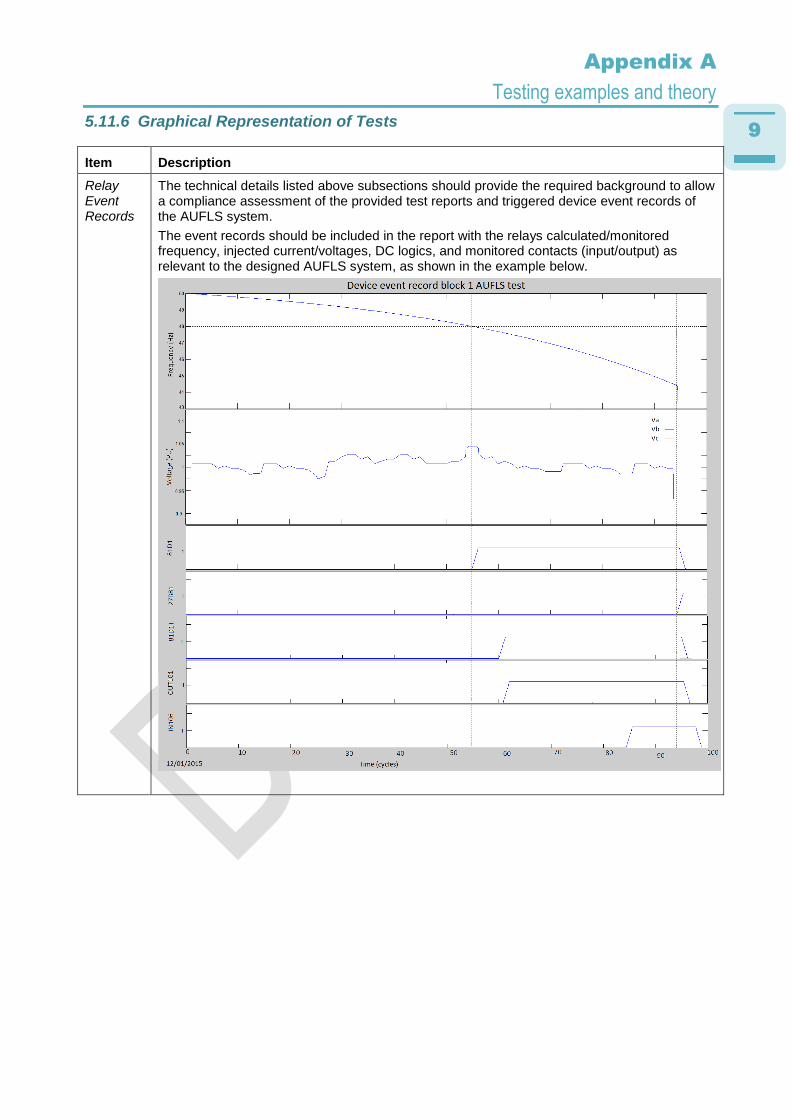
Relay Event Records
The technical details listed above subsections should provide the required background to allow a compliance assessment of the provided test reports and triggered device event records of the AUFLS system.
The event records should be included in the report with the relays calculated/monitored frequency, injected current/voltages, DC logics, and monitored contacts (input/output) as relevant to the designed AUFLS system, as shown in the example below.

10
Appendix A
Testing examples and theory
End to end operation
The total operating time requirements set out in the TRS must be itemised in the Test Report complete with supporting test results and additional documentation where required.
The total operation time can be proven in a few different ways, for example, reports from an external monitoring devices such as fault recorders or on a test set report with operation times and details about how the test set was connected. This information must include the passing criteria programed in the test set and supporting analysis of device records as appropriate to ensure a clear understanding of the AUFLS systems compliance with the TRS.
An example of a test set report screen is given below: