3VT1 Molded Case Circuit Breakers up to 160 A - Lore Electro · 3VT1 Molded Case Circuit Breakers...
46
2 Siemens LV 36 · 2008 3VT1 Molded Case Circuit Breakers up to 160 A General data 2/2 - Overview Circuit breakers · Switch disconnetors 2/3 - Overview 2/3 - Selection and ordering data Accessories and Components Auxiliary switches · Auxiliary releases 2/6 - Overview 2/6 - Selection and ordering data Manual-/motorized operating mechanisms 2/7 - Selection and ordering data Connecting accessories 2/9 - Selection and ordering data 3VT1 Molded Case Circuit Breakers up to 160 A Circuit breakers · Switch disconnetors 2/11 - Design 2/12 - Technical specifications 2/13 - Schematics 2/15 - Characteristics Accessories and Components Axiliary switches 2/22 - Overview 2/23 - Function 2/23 - Technical specifications Auxiliary releases 2/24 - Design 2/24 - Technical specifications Manual operating mechanisms 2/25 - Design Motorized operating mechanism 2/27 - Design 2/28 - Schematics Project planning aids 2/35 Dimensional drawings 3VT1 Molded Case Circuit Breakers up to 160 A Catalog Technical Information
Transcript of 3VT1 Molded Case Circuit Breakers up to 160 A - Lore Electro · 3VT1 Molded Case Circuit Breakers...

2
Siemens LV 36 · 2008
3VT1 Molded Case Circuit Breakers up to 160 A
General data2/2 - Overview
Circuit breakers · Switch disconnetors
2/3 - Overview
2/3 - Selection and ordering data
Accessories and Components
Auxiliary switches · Auxiliary releases
2/6 - Overview
2/6 - Selection and ordering data
Manual-/motorized operating mechanisms
2/7 - Selection and ordering data
Connecting accessories
2/9 - Selection and ordering data
3VT1 Molded Case Circuit Breakers up to 160 A
Circuit breakers · Switch disconnetors
2/11 - Design
2/12 - Technical specifications
2/13 - Schematics
2/15 - Characteristics
Accessories and Components
Axiliary switches
2/22 - Overview
2/23 - Function
2/23 - Technical specifications
Auxiliary releases
2/24 - Design
2/24 - Technical specifications
Manual operating mechanisms
2/25 - Design
Motorized operating mechanism
2/27 - Design
2/28 - Schematics
Project planning aids
2/35 Dimensional drawings
3VT1 Molded Case Circuit Breakers up to 160 A
Catalog
Technical Information

3VT1 Molded Case Circuit Breakers up to 160 A
General data
2/2 Siemens LV 36 · 2008
2
n Overview
Versions and accessories
1. 3VT circuit breaker 13. Locking type lever 25. Mechanical interlocking2. Circular conductor terminals 14. Front manual operating mechanism 26. Mechanical parallel switching3. Front connection 15. Front manual operating mechanism 27. Lateral motorized operating mechanism4. Rear connection 16. Lateral manual operating mechanism (right)5. Potential terminals 17. Lateral manual operating mechanism (left)6. Connecting bus with increased pole spacing 18. Non lockable knob7. Adapter to install on 35 mm DIN rail 19. Lockable knob8. Phase barriers 20. Lockable knob9. Signal switch 21. Coupling driver10. Auxiliary switch 22. Coupling driver11. Shunt release 23. Telescopic extension shaft12. Undervoltage release 24. Extension shaft

3VT1 Molded Case Circuit Breakers up to 160 A
Circuit breakers · Switch disconnectors
2/3Siemens LV 36 · 2008
2
n Overview
Circuit breakers
Circuit breakers, 3-pole version
The 3-pole version of the circuit breakers consits pf:• 2 connecting sets for connecting Cu/Al cables1) with cross-
sections of 2.5 ... 95 mm2 (these terminals are fitted to the circuit breaker)
• 3VT9 100-8CE30 phase barriers• A set of two mounting bolts (M3 x 30)• A conductor holder
Characteristic M (motor): motor protection
Circuit breakers, 4-pole version
The 4-pole version of the circuit breakers consists of:• 2 connecting sets for connecting Cu/AI cables1) with cross-
sections of 2.5 ... 95 mm2
(these terminals are fitted to the circuit breaker)• 3VT9 100-8CE30 and 3VT9 100-8CE00 phase barriers • 2 sets of two mounting bolts (M3 x 30)• A conductor holder (installed in the circuit breaker)
Releases:
Characteristic L (line)• Protecting lines with low starting currents• Without Ir regulation
Characteristic D (distribution)• Protecting lines and transformers
Characteristic N (only short-circuit release)• Without Ir regulation
Switch disconnectors
Switch disconnectors, 3-pole version
The 3-pole version of the switch disconnectors consits of:• 2 connecting sets for connecting Cu/Al cables1) with cross-
sections of 2.5 ... 95 mm2 (these terminals are fitted to the switch disconnector)
• 3VT9 100-8CE30 phase barriers • A set of two mounting bolts (M3 x 30)• A conductor holder
Switch disconnectors, 4-pole version
The 4-pole version of the switch disconnectors consits of:• 2 connecting sets for connecting Cu/Al cables1) with cross-
sections of 2.5 ... 95 mm2 (these terminals are fitted to the switch disconnector)
• 3VT9 100-8CE30 and 3VT9 100-8CE00 phase barriers• 2 sets of two mounting bolts (M3 x 30)• Conductor holder (installed in the switch disconnector)
Connection
When connecting the main circuit, the dimensions of the deion-ization space of the circuit breaker must be observed, depend-ing on the type of connection (see pages 2/35 and 2/36).1) For other connection methods, use connecting parts
(see page 2/9).
n Selection and ordering data
Rated current In Current setting of the inverse-time delayed overload release „L“ Ir
DT Order No. PS* Weight per PU approx.
A A kg
Circuit breakers for system protection characteristic L
TM, LI function, 3P
• with fixed thermal overload release, fixed short-circuit release
40 160 B 3VT1 704-2DA36-0AA0 1 unit 1.04350 200 B 3VT1 705-2DA36-0AA0 1 unit 1.04363 252 B 3VT1 706-2DA36-0AA0 1 unit 1.06280 320 B 3VT1 708-2DA36-0AA0 1 unit 1.062
100 400 B 3VT1 710-2DA36-0AA0 1 unit 1.047125 500 B 3VT1 712-2DA36-0AA0 1 unit 1.047160 640 B 3VT1 716-2DA36-0AA0 1 unit 1.074
TM, LI function, 3P+N, for unprotected conductors
• with fixed thermal overload release, fixed short-circuit release
40 160 B 3VT1 704-2EA46-0AA0 1 unit 1.33650 200 B 3VT1 705-2EA46-0AA0 1 unit 1.33663 252 B 3VT1 706-2EA46-0AA0 1 unit 1.33680 320 B 3VT1 708-2EA46-0AA0 1 unit 1.336
100 400 B 3VT1 710-2EA46-0AA0 1 unit 1.336125 500 B 3VT1 712-2EA46-0AA0 1 unit 1.336160 640 B 3VT1 716-2EA46-0AA0 1 unit 1.336
TM, LI function, 4P
• with fixed thermal overload release, fixed short-circuit release
40 160 B 3VT1 704-2EH46-0AA0 1 unit 1.33650 200 B 3VT1 705-2EH46-0AA0 1 unit 1.33663 252 B 3VT1 706-2EH46-0AA0 1 unit 1.33680 320 B 3VT1 708-2EH46-0AA0 1 unit 1.336
100 400 B 3VT1 710-2EH46-0AA0 1 unit 1.336125 500 B 3VT1 712-2EH46-0AA0 1 unit 1.336160 640 B 3VT1 716-2EH46-0AA0 1 unit 1.336
* You can order this quantity or a multiple thereof.

3VT1 Molded Case Circuit Breakers up to 160 A
Circuit breakers · Switch disconnectors
2/4 Siemens LV 36 · 2008
2
Circuit breakers for system protection characteristic D
TM, LI function 3P
• with adjustable thermal overload release, adjustable short-circuit release
16 160 ... 240 B 3VT1 701-2DC36-0AA0 1 unit 1.04820 200 ... 300 B 3VT1 702-2DC36-0AA0 1 unit 1.04825 250 ... 375 B 3VT1 792-2DC36-0AA0 1 unit 1.04332 160 ... 320 B 3VT1 703-2DC36-0AA0 1 unit 1.047
40 200 ... 400 B 3VT1 704-2DC36-0AA0 1 unit 1.04350 250 ... 500 B 3VT1 705-2DC36-0AA0 1 unit 1.04363 315 ... 630 B 3VT1 706-2DC36-0AA0 1 unit 1.06280 400 ... 800 B 3VT1 708-2DC36-0AA0 1 unit 1.062
100 500 ... 1000 B 3VT1 710-2DC36-0AA0 1 unit 1.047125 625 ... 1250 B 3VT1 712-2DC36-0AA0 1 unit 1.047160 800 ... 1600 B 3VT1 716-2DC36-0AA0 1 unit 1.074
TM, LI function 3P+N, for unprotected N-conductor
• with adjustable thermal overload release, adjustable short-circuit release
16 160 ... 240 B 3VT1 701-2EC46-0AA0 1 unit 1.33620 200 ... 300 B 3VT1 702-2EC46-0AA0 1 unit 1.33625 250 ... 375 B 3VT1 792-2EC46-0AA0 1 unit 1.33632 160 ... 320 B 3VT1 703-2EC46-0AA0 1 unit 1.336
40 200 ... 400 B 3VT1 704-2EC46-0AA0 1 unit 1.33650 250 ... 500 B 3VT1 705-2EC46-0AA0 1 unit 1.33663 315 ... 630 B 3VT1 706-2EC46-0AA0 1 unit 1.33680 400 ... 800 B 3VT1 708-2EC46-0AA0 1 unit 1.336
100 500 ... 1000 B 3VT1 710-2EC46-0AA0 1 unit 1.336125 625 ... 1250 B 3VT1 712-2EC46-0AA0 1 unit 1.336160 800 ... 1600 B 3VT1 716-2EC46-0AA0 1 unit 1.336
TM, LI function 4P
• with adjustable thermal overload release, adjustable short-circuit release
16 160 ... 240 B 3VT1 701-2EJ46-0AA0 1 unit 1.33620 200 ... 300 B 3VT1 702-2EJ46-0AA0 1 unit 1.33625 250 ... 375 B 3VT1 792-2EJ46-0AA0 1 unit 1.33632 160 ... 320 B 3VT1 703-2EJ46-0AA0 1 unit 1.336
40 200 ... 400 B 3VT1 704-2EJ46-0AA0 1 unit 1.33650 250 ... 500 B 3VT1 705-2EJ46-0AA0 1 unit 1.33663 315 ... 630 B 3VT1 706-2EJ46-0AA0 1 unit 1.33680 400 ... 800 B 3VT1 708-2EJ46-0AA0 1 unit 1.380
100 500 ... 1000 B 3VT1 710-2EJ46-0AA0 1 unit 1.336125 625 ... 1250 B 3VT1 712-2EJ46-0AA0 1 unit 1.336160 800 ... 1600 B 3VT1 716-2EJ46-0AA0 1 unit 1.336
Rated current In Current setting of the inverse-time delayed overload release „L“ Ir
DT Order No. PS* Weight per PU approx.
A A kg
* You can order this quantity or a multiple thereof.

3VT1 Molded Case Circuit Breakers up to 160 A
Circuit breakers · Switch disconnectors
2/5Siemens LV 36 · 2008
2
Rated current In Current setting of the short-circuit release „I“ Ii
DT Order No. PS* Weight per PU approx.
A A kg
Circuit breakers only for short-circuit protection
TM, I function, 3P
• without overload release, with adjustable short-circuit release
32 160 ... 320 B 3VT1 703-2DB36-0AA0 1 unit 1.04340 200 ... 400 B 3VT1 704-2DB36-0AA0 1 unit 1.04350 250 ... 500 B 3VT1 705-2DB36-0AA0 1 unit 1.04863 315 ... 630 B 3VT1 706-2DB36-0AA0 1 unit 1.048
80 400 ... 800 B 3VT1 708-2DB36-0AA0 1 unit 1.048100 500 ... 1000 B 3VT1 710-2DB36-0AA0 1 unit 1.050125 625 ... 1250 B 3VT1 712-2DB36-0AA0 1 unit 1.059160 800 ... 1600 B 3VT1 716-2DB36-0AA0 1 unit 1.048
TM, I function, 3P+N, for unprotected conductors
• without overload release, with adjustable short-circuit release
32 160 ... 320 B 3VT1 703-2EB46-0AA0 1 unit 1.33640 200 ... 400 B 3VT1 704-2EB46-0AA0 1 unit 1.33650 250 ... 500 B 3VT1 705-2EB46-0AA0 1 unit 1.33663 315 ... 630 B 3VT1 706-2EB46-0AA0 1 unit 1.336
80 400 ... 800 B 3VT1 708-2EB46-0AA0 1 unit 1.336100 500 ... 1000 B 3VT1 710-2EB46-0AA0 1 unit 1.336125 625 ... 1250 B 3VT1 712-2EB46-0AA0 1 unit 1.336160 800 ... 1600 B 3VT1 716-2EB46-0AA0 1 unit 1.336
TM, LI function, 4P
• without thermal overload releases, adjustable short-circuit releases
32 160 ... 320 B 3VT1 703-2EG46-0AA0 1 unit 1.33640 200 ... 400 B 3VT1 704-2EG46-0AA0 1 unit 1.33650 250 ... 500 B 3VT1 705-2EG46-0AA0 1 unit 1.33663 315 ... 630 B 3VT1 706-2EG46-0AA0 1 unit 1.336
80 400 ... 800 B 3VT1 708-2EG46-0AA0 1 unit 1.336100 500 ... 1000 B 3VT1 710-2EG46-0AA0 1 unit 1.336125 625 ... 1250 B 3VT1 712-2EG46-0AA0 1 unit 1.336160 800 ... 1600 B 3VT1 716-2EG46-0AA0 1 unit 1.336
Circuit Breakers for starter combinations characteristic M
TM, LI function, 3P
• with adjustable thermal overload releases, fixed short-circuit releases
16 12.5 ... 16 B 3VT1 701-2DM36-0AA0 1 unit 1.04820 16 ... 20 B 3VT1 702-2DM36-0AA0 1 unit 1.04825 20 ... 25 B 3VT1 792-2DM36-0AA0 1 unit 1.04332 25 ... 32 B 3VT1 703-2DM36-0AA0 1 unit 1.043
40 32 ... 40 B 3VT1 704-2DM36-0AA0 1 unit 1.04350 40 ... 50 B 3VT1 705-2DM36-0AA0 1 unit 1.04363 50 ... 63 B 3VT1 706-2DM36-0AA0 1 unit 1.06280 63 ... 80 B 3VT1 708-2DM36-0AA0 1 unit 1.059
100 80 ... 100 B 3VT1 710-2DM36-0AA0 1 unit 1.047
Switch disconnectors
Non-automatic molded case circuit breakers without overload release, without short-circuit release
160 3-pole B 3VT1 716-2DE36-0AA0 1 unit 1.043
160 4-pole B 3VT1 716-2EE46-0AA0 1 unit 1.336
* You can order this quantity or a multiple thereof.

3VT1 Molded Case Circuit Breakers up to 160 AAccessories and Components
Auxiliary switches · Auxiliary releases
2/6 Siemens LV 36 · 2008
2
n Overview
The circuit breakers can be equipped with
• auxiliary switches and• alarm switches.
For remote switching, shunt releases can be built in.
Undervoltage releases can be used to protect motors and other equipment against damage in case of undervoltage.
n Selection and ordering data
Rated control supply voltage Us/Frequency
DT Order No. PS* Weight per PU approx.
AC 50/60 Hz/DC kg
Auxiliary switches and alarm switches
Auxiliary switches for signaling the state of the main contacts
• AC/DC 60 ... 250 V B 3VT9 100-2AB10 1 unit 0.010• AC/DC 5 ... 60 V B 3VT9 100-2AB20 1 unit 0.010
Alarm switches for signaling the tripping of the circuit breaker by an overcurrent release
• AC/DC 60 ... 250 V B 3VT9 100-2AH10 1 unit 0.010• AC/DC 5 ... 60 V B 3VT9 100-2AH20 1 unit 0.010
Shunt releases
• AC/DC 24, 48 V B 3VT9 100-1SC00 1 unit 0.050• AC 110, 230 V/DC 110, 220 V B 3VT9 100-1SD00 1 unit 0.050• AC 230, 400 V/DC 220 V B 3VT9 100-1SE00 1 unit 0.050
Undervoltage releases
• AC 24, 48 V B 3VT9 100-1UC00 1 unit 0.050• AC 110, 230 V B 3VT9 100-1UD00 1 unit 0.050• AC 230, 400 V B 3VT9 100-1UE00 1 unit 0.050
• DC 24, 48 V B 3VT9 100-1UU00 on req.• DC 110, 220 V B 3VT9 100-1UV00 on req.• DC 220 V B 3VT9 100-1UW00 on req.
* You can order this quantity or a multiple thereof.

3VT1 Molded Case Circuit Breakers up to 160 AAccessories and Components
Manual/motorized operating mechanisms
2/7Siemens LV 36 · 2008
2
n Selection and ordering data
Manual operating mechanisms
The rotary operating mechanism is to be completed:
• For simple rotary operation of the switch unit:- 3VT9 100-3HE../HF.. knob
• For operating through the switchgear cabinet door:- 3VT9 100-3HE../HF.. knob- 3VT9 100-3HG../HH.. coupling driver- 3VT9 100-3HJ.. extension shaft,
• For rotary operating mechanism for lateral operation:- 3VT9 100-3HE../HF.. knob- 3VT9 100-3HG../HH.. coupling driver
- 3VT9 100-3HJ.. extension shaft
Mechanical interlocking and parallel switching
• The mechanical interlock is to be completed:- 2 x 3VT9 200-3HA/HB.. rotary operating mechanisms
(cannot be used with rotary operating mechanism for lateral operation)
- 2 x 3VT9 200-3HE/HF.. knobs (standard) or 1 x 3VT9 200-3HE/HF.. knob (parallel switching)
Version Color DT Order No. PS* Weight per PU approx.
kg
Manual operating mechanisms
Rotary operating mechanism
• locking not possible gray B 3VT9 100-3HA10 1 unit 0.079• lockable with padlock gray B 3VT9 100-3HA20 1 unit 0.079
• lockable with padlock yellow B 3VT9 100-3HB20 1 unit 0.079
• for lateral operation, mounted on left side, locking not possible
gray B 3VT9 100-3HC10 1 unit 0.137
• for lateral operation, mounted on right side, locking not possible
gray B 3VT9 100-3HD10 1 unit 0.137
Knob
• locking not possible black B 3VT9 100-3HE10 1 unit 0.019• lockable with padlock black B 3VT9 100-3HE20 1 unit 0.019
• lockable with padlock red B 3VT9 100-3HF20 1 unit 0.019
Coupling driver for door-coupling operating mechanism
Is used with the 3VT9 100-3HE10 or 3VT9 100-3HE20 black knob
• degree of protection IP40 black B 3VT9 100-3HG10 1 unit 0.042• degree of protection IP66 black B 3VT9 100-3HG20 1 unit 0.042
Is used in with the 3VT9 100-3HF20 red knob
• degree of protection IP40 yellow B 3VT9 100-3HH10 1 unit 0.042• degree of protection IP66 yellow B 3VT9 100-3HH20 1 unit 0.042
Extension shaft
• length 350 mm, may be shortened B 3VT9 100-3HJ10 1 unit 0.113
• lenght 199 ... 352 mm, telescopic B 3VT9 100-3HJ20 1 unit 0.092
* You can order this quantity or a multiple thereof.
3VT1 Molded Case Circuit Breakers up to 160 AAccessories and Components
Manual/motorized operating mechanisms
2/8 Siemens LV 36 · 2008
2
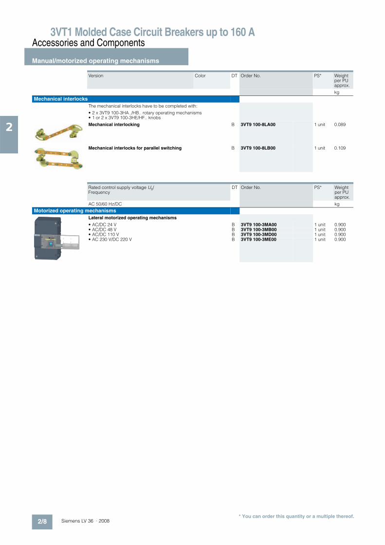
Mechanical interlocks
The mechanical interlocks have to be completed with:
• 2 x 3VT9 100-3HA../HB.. rotary operating mechanisms• 1 or 2 x 3VT9 100-3HE/HF.. knobs
Mechanical interlocking B 3VT9 100-8LA00 1 unit 0.089
Mechanical interlocks for parallel switching B 3VT9 100-8LB00 1 unit 0.109
Version Color DT Order No. PS* Weight per PU approx.
kg
Rated control supply voltage Us/ Frequency
DT Order No. PS* Weight per PU approx.
AC 50/60 Hz/DC kg
Motorized operating mechanisms
Lateral motorized operating mechanisms
• AC/DC 24 V B 3VT9 100-3MA00 1 unit 0.900• AC/DC 48 V B 3VT9 100-3MB00 1 unit 0.900• AC/DC 110 V B 3VT9 100-3MD00 1 unit 0.900• AC 230 V/DC 220 V B 3VT9 100-3ME00 1 unit 0.900
* You can order this quantity or a multiple thereof.

3VT1 Molded Case Circuit Breakers up to 160 AAccessories and Components
Connecting accessories
2/9Siemens LV 36 · 2008
2
n Selection and ordering data
Version Conductor cross-sections S
Type of connection
DT Order No. PS* Weight per PU approx.
mm2 kg
Terminals for fixed-mounted circuit breakers
Connecting set for 3-pole version
Terminals for front connection -- Cu/Al busbars, cable lugs
B 3VT9 100-4TA30 1 unit 0.045
Terminals for circular conductors 2 x 25 ... 120 Cu/Al cable B 3VT9 100-4TF30 1 unit 0.180
Terminal cover, degree of protection IP20, is Included in the scope of supply
Terminals for rear connection Cu/Al busbars, cable lugs
B 3VT9 100-4RC30 1 unit 0.320
Isolating terminals 1.5 ... 2.5; 4 ... 6
Cu flexible conductors
B 3VT9 100-4TN30 1 unit 0.010
Front connection bars 1.5 ... 2.5; 4 ... 6
Cu/Al busbars, cable lugs
B 3VT9 100-4ED30 1 unit 0.103
Terminals for 4-pole version
Terminals for front connection
For 4th pole (to be used with 3VT9 100-4TA30 connecting set)
-- Cu/Al busbars, cable lugs
B 3VT9 100-4TA00 1 unit 0.015
Terminals for circular conductors 2 x 25 ... 120 Cu/Al cable B 3VT9 100-4TF40 1 unit 0.250
Terminal cover, degree of protection IP20, is included in the scope of supply
Terminals for rear connection
For 4th pole (to be used with 3VT9 100-4RC30 connecting set)
Cu/Al-busbars, cable lugs
B 3VT9 100-4RC00 1 unit 0.080
Isolating terminals
For 4th pole (to be used with 3VT9 100-4TN30 connecting set)
1,5 ... 2,5; 4 ... 6
Cu flexible conductor
B 3VT9 100-4TN00 1 unit 0.010
* You can order this quantity or a multiple thereof.

3VT1 Molded Case Circuit Breakers up to 160 AAccessories and Components
Mounting accessories
2/10 Siemens LV 36 · 2008
2
n Selection and ordering data
Version Conductor cross-sections S
Connection DT Order No. PS* Weight per PU approx.
mm2 kg
Accessories
3-pole version
Phase barriers for circuit breakers
Included in the scope of supply of the circuit breaker or switch disconnector
In case of feed-in from below, (power supply connected to terminals 2, 4 ,6), it is necessary to install these barriers on the bottom side
For more information, see page 2/35.
B 3VT9 100-8CE30 1 unit 0.030
Terminal protection cover, degree of protection IP20
Increases degree of protection of the connection point to degree of protection IP20, e.g. when used with cable lugs.
B 3VT9 100-8CA30 1 unit 0.050
Locking devices for knob
• Enables locking of circuit breaker or switch disconnector in „switched off manually“ position
• Locking is possible using padlock with a shank diameter of up to 3 ... 4 mm.
3VT9 100-8HL00 on req.
4-pole version
Phase barriers for circuit breakers
• Included in the scope of supply of circuit breaker or switch disconnector• In case of feed-in from below, (power supply connected to terminals 2, 4, 6,
N), it is necessary to install these barriers on the bottom side
For more information, see page 2/36.
B 3VT9 100-8CE00 1 unit 0.020
Terminal cover, degree of protection IP20
Increases the degree of protection of the connecting point to degree of protection IP20, e.g. when used with cable lugs
B 3VT9 100-8CA40 1 unit 0.080
Extension cables for motorized operating mechanisms B 3VT9 100-3MF00 1 unit 0.100
Mounting adapters
3-pole version
For mounting on a 35 mm standard mounting rails
For dimensions, see page 2/44.
B 3VT9 100-4PP30 1 unit 0.050
* You can order this quantity or a multiple thereof.

3VT1 Molded Case Circuit Breakers up to 160 A
Circuit breakers · Switch disconnectors
2/11Siemens LV 36 · 2008
2
n Design
Installation and connection
Main circuit
• Is connected, using Cu or AI busbars, cables, and possibly cables with cable lugs.
• For further connecting options, connecting sets can be used (see page 2/9).
• Generally, conductors from the power supply are connected to input terminals 1, 3, 5, (N) and conductors from the load to terminals 2, 4, 6, (N). It is possible to reverse the current flow inside the unit (i. e. infeed from below) without reducing the rated short-circuit ultimate breaking capacity Icu.
• In case of infeed from below, the units must be fitted with 3VT9 100-8CE30 phase barriers also on the side of terminals 2, 4, 6 (see pages 2/35 and 2/36).
• We recommend painting the connection busbars.• Input and output connectors/busbars must be mechanically
reinforced to avoid transferring electrodynamic forces to the circuit breaker during short-circuiting.
• The way of connecting the power circuit must observe the deionization space of the circuit breaker/switch disconnector (see pages 2/35 and 2/36).
Recommended cross-section of cables, busbars and flexibars
Auxiliary circuits
Switches, shunt trip releases or undervoltage releases are con-nected directly to the terminals of the circuit breaker/switch dis-connector using flexible Cu conductors with cross-section 0.5 ... 1 mm2.
Conductor cross-sections of main terminals
Rated current In
Conductor cross-section S Busbars W x H
Cu AI Cu AI
A mm2 mm2 mm mm
16 2,5 -- -- --20 2,5 -- -- --25 4 -- -- --
32 6 -- -- --40 10 -- -- --50 10 16 -- --63 16 25 -- --
80 25 35 -- --100 35 50 16 x 2; 12 x 3 16 x 4; 12 x 4125 50 95 16 x 4; 12 x 4 16 x 5; 12 x 6160 70 120 16 x 5; 12 x 6 --
Order No. Maximum permitted current Imax
Maximum permissible conductor cross-sectionsS Max. width of busbars and cable lugs
Technical informationCable type
Sector-shaped conductor, stranded
Sector-shaped con-ductor, solid
Round conductor, stranded
Round conductor, solid
A mm2 mm2 mm2 mm2 mm
3-pole
3VT9 100-4TF30 160 2 x 25 ... 120 2 x 25 ... 120 2 x 25 ... 120 2 x 25 ... 120 pg. D173VT9 100-4TA30 160 163VT9 100-4RC30 160 16 pg. D18
3VT9 100-4TN30 10/16 1,5 ... 2,5/4 ... 6 -- --3VT9 100-4ED30 160 30 pg. D18
4-pole
3VT9 100-4TF40 160 2 x 25 ... 120 2 x 25 ... 120 2 x 25 ... 120 2 x 25 ... 120 pg. 123VT9 100-4TA00 160 16
3VT9 100-4RC00 160 16 pg. 133VT9 100-4TN00 10/16 1,5 ... 2,5/4 ... 6

3VT1 Molded Case Circuit Breakers up to 160 A
Circuit breakers · Switch disconnectors
2/12 Siemens LV 36 · 2008
2
n Technical specifications
4 available,-- unavailable,+ in preparation
1) When reversing the circuit breaker connection (power supply connected to terminals 2, 4, 6, (N) output to terminals 1, 3, 5, (N)), Icu does not change.
2) Ranges of rated currents vary according to characteristics, see page 2/16.3) Permissible load of N pole is 100%.
Specifications 3VT1 7..-2..36-0AA0 3VT1 716-2DE36-0AA0 3VT1 7..-2..46-0AA0 3VT1 716-2EE46-0AA0
Order No. Circuit Breakers Switch disconnectors Circuit Breakers 3) Switch Disconnectors
Number of poles 3 4
Standards EN 60 947-2, IEC 947-2
EN 60 947-3,IEC 947-3 EN 60 947-2, IEC 947-2 EN 60 947-3,IEC 947-3
Approval marks
Rated current In A 16 ... 1602) -- 16 ... 1602) --
Rated uninterrupted current Iu A 16 ... 1602) 160 16 ... 1602) 160
Rated operational current Ie A -- 160 -- 160
Rated operational voltage Ue V max. AC 690 max. AC 690max. AC 440
Rated frequency fn Hz 50/60
Rated impulse withstand voltage Uimp kV 8
Rated insulation voltage Ui V 690
Utilization category • selectivity AC 690 V A -- A --• switching mode AC-3 (16 ... 100 A)
AC-2 (100 ... 160 A)AC-23 A AC-3 (16 ... 100 A)
AC-2 (100 ... 160 A)DC-22 AAC-23 A
Rated short-time withstand current Icw /t -- 2 kA/ 1 s -- 2 kA/1 s
Rated ultimate short-circuit breaking capacity (rms value)1)
Icu/Ue
6 kA/AC 690 V12 kA/AC 500 V25 kA/AC 415 V40 kA/AC 230 V
-- 13kA/DC 440V( !"!max. 5 ms)6 kA/AC 690 V12 kA/AC 500 V25 kA/AC 415 V40 kA/AC 230 V
Off-time at Icu ms 7 -- 7 --
Rated service short-circuit breaking capacity (rms value) Ics/Ue
3 kA/AC 690 V6 kA/AC 500 V13 kA/AC 415 V20 kA/AC 230 V
-- 13kA/DC 440V( "!max. 5 ms)3 kA/AC 690 V6 kA/AC 500 V13 kA/AC 415 V20 kA/AC 230 V
Rated short-circuit making capacity (peak value) Icm/Ue
52 kA/AC 415 V 2.8 kA/AC 415 V 52 kA/AC 415 V 2.8 kA/AC 415 V
Losses per pole at In = 160 A W see table, page 2/14 15
Mechanical endurance cycles 20 000
Electrical endurance (Ue = AC 415 V ) cycles 6 000
Frequency of switching cycles/hr
120
Operating force N 55 65
Front-side device protection IP40
Terminal protection IP20
Operating conditions
Reference ambient temperature °C 40
Ambient temperature range °C -40 ... +55
Working environment dry and tropical climate
Degree of pollution 3
Max. elevation m 2000
Seismic resistance Hz 3g (8 ... 50 )
Design modifications
Front/rear connection 4/4
Plug-in version --
Withdrawable version --
Accessories
Switches - auxiliary/relative/signal/leading 4/–/4/–
Shunt trip/with signal switch 4/4
Undervoltage release/with leading switch/with signal switch
4/–/4
Front hand drive/lateral drive right/left 4/4/4
Mechanical interlocking to the manual drive by Bowden wire
--/-- –/4
Motor. oper. mechanism/with oper. counter +/+ +
Locking-type lever 4
3VT1 Molded Case Circuit Breakers up to 160 A
Circuit breakers · Switch disconnectors
2/13Siemens LV 36 · 2008
2
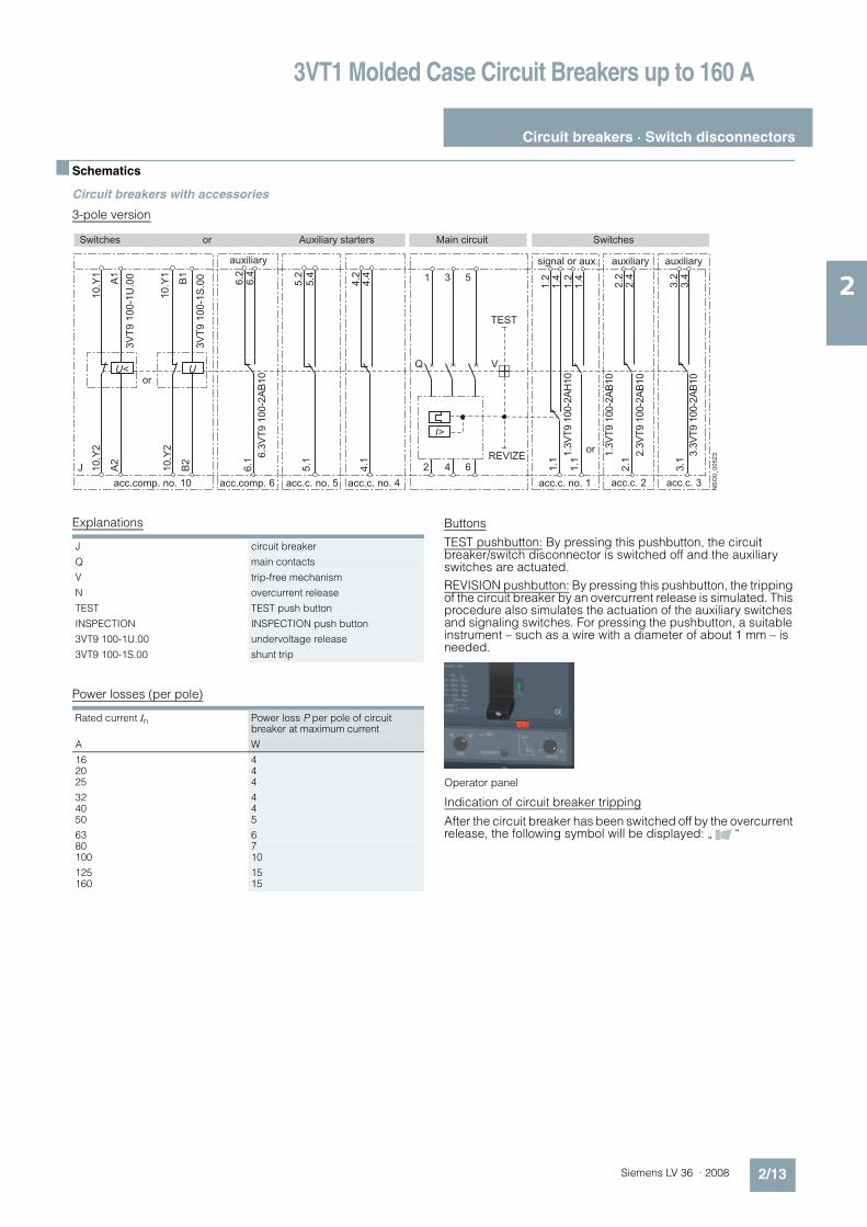
n Schematics
Circuit breakers with accessories
3-pole version
Explanations
Power losses (per pole)
Buttons
TEST pushbutton: By pressing this pushbutton, the circuit breaker/switch disconnector is switched off and the auxiliary switches are actuated.
REVISION pushbutton: By pressing this pushbutton, the tripping of the circuit breaker by an overcurrent release is simulated. This procedure also simulates the actuation of the auxiliary switches and signaling switches. For pressing the pushbutton, a suitable instrument – such as a wire with a diameter of about 1 mm – is needed.
Operator panel
Indication of circuit breaker tripping
After the circuit breaker has been switched off by the overcurrent release, the following symbol will be displayed: „ “
A1
10.Y2
A2
10.Y2
B2
10.Y1
B1
10.Y1
6.4
6.1
5.1
4.1
6.2
I>
VQ
REVIZE
TEST
1.21.4
NSO0_00523
1.1
1.1
1.21.4
1.3VT9 100-2AH10
2.22.4
3.23.4
3VT9 100-1U.00
3VT9 100-1S.00
4.4
4.2
5.4
5.2
J
6.3VT9 100-2AB10
3.3VT9 100-2AB10
2.3VT9 100-2AB10
1.3VT9 100-2AB10
2.1
3.1
31 5
2 4 6
U< U
auxiliary signal or aux. auxiliary auxiliary
Switches or Auxiliary starters Main circuit Switches
acc.comp. no. 10 acc.comp. 6 acc.c. no. 1 acc.c. 2 acc.c. 3acc.c. no. 5 acc.c. no. 4
or
or
J circuit breaker
Q main contacts
V trip-free mechanism
N overcurrent release
TEST TEST push button
INSPECTION INSPECTION push button
3VT9 100-1U.00 undervoltage release
3VT9 100-1S.00 shunt trip
Rated current In Power loss P per pole of circuit breaker at maximum current
A W
16 420 425 4
32 440 450 5
63 680 7100 10
125 15160 15

3VT1 Molded Case Circuit Breakers up to 160 A
Circuit breakers · Switch disconnectors
2/14 Siemens LV 36 · 2008
2
4-pole version
Explanations
1) The voltage on terminals 6, 7, 8 is the same as Un of the motorized operat-ing mechanism.
L+
Q3
X3
MP
X32
4
5
3
6
1
7 8
M
B
P
HL1 HL2 HL3 HL4N-
9.4
9.1
9.2
3VT9 100-2AB.0
8.4
8.1
8.2
3VT9 100-2AB.0
7.4
7.1
7.2
3VT9 100-2AB.0
A
J
6.4
6.1
6.2
3VT9 100-2AB.0
5.4
5.1
5.2
3VT9 100-2AB.0
4.4
4.1
4.2
3VT9 100-2AB.0
I>
V
TEST
1.21.4
NSO0_00001
1.1
1.1
1.21.4
3VT9 100-2AH.0
3VT9 100-2AB.0
2.22.4
3VT9 100-2AB.0
3.23.4
3VT9 100-2AB.0
2.1
3.1
A1
U<
3VT9 100-1U.00 A1
U
3VT9 100-1S.00
A
N
T
10.Y2
10.Y2
10.Y1
10.Y1
A2
B2
2 4 6
N
Q
1 3 5
B
J
MP control circuit
ON
OFF
Motor drive
MP control circuit, signalling
Switches
auxiliary auxiliary auxiliary
auxiliary auxiliary auxiliary signal or aux. auxiliary auxiliary
Switches or Auxiliary starters Main circuit Switches
acc.c. no. 9 acc.c. no. 8 acc.c. no. 7
acc.c. no. 6 acc.c. no. 5 acc.c. no. 4 acc.c. no. 1 acc.c. 2 acc.c. 3acc.comp. no. 10
or
orREVIZE
MP 3VT9 100-3M.00 motorized operating mechanism
M motor
P gearbox
X3 connector for connection of control and signaling circuits
B recommended connection of control circuits - is not part of MP
ON pushbutton
OFF pushbutton
Q3 motorized operating mechanism for the circuit breaker (see page 22)
J 3VT1 circuit breakers
Q main contacts
T thermomagnetic overcurrent release3P+N (3 poles protected, N-pole unprotected)4P (all four poles protected)
V trip-free mechanism
TEST release test pushbutton
REVIZE release revision pushbutton
3VT9 100-1U.00 undervoltage release
3VT9 100-1S.00 shunt trip
HL1 remote failure signalling (unreliable making or breaking), max. permissible load10 W1)
HL2 signalling of circuit breaker lever „wound up“ position, max. permissible load 10 W1)
HL3 signalling of opening of the front safty cover of the drive, max. permissible load 10 W1)
HL4 signalling of extension of the drive locking bar, max. per-missible load 10 W1)
TEST pushbutton

3VT1 Molded Case Circuit Breakers up to 160 A
Circuit breakers · Switch disconnectors
2/15Siemens LV 36 · 2008
2
n Characteristics
Overcurrent releases, 3-pole version
Overcurrent releases are integrated in circuit breakers. Releases cannot be demounted and exchanged.
Tripping characteristics
Circuit breakers are available with four types of tripping charac-teristics. They are designated with the letters:
„L“ - lines Protecting lines with low starting currents
„D“ - distribution Protecting lines and transformers
„M“ - motorMotor protection
„N“ - short-circuit release only
• 3VT1 circuit breakers with characteristic „L“ have a given and fixed rated current value. The circuit breakers are produced with In values in a standardized current range from 40 A to 160 A (see „Ranges of overcurrent releases and their possible set-tings“). Short-circuit releases are fixed at 4 x In.
• 3VT1 circuit breakers with characteristic „D“ have the option of setting to a reduced current in a range of approximately 0.75 ... 1 In. The circuit breakers are produced with In values in a standardized current range from 16 A to 160 A (see „Ranges of overcurrent releases and their possible settings“). The short-circuit release is adjustable. Setting values are given in the table on page 2/16.
• 3VT1 circuit breakers with characteristic „M“ have the option of setting a reduced current in a range of approximately 0.75 ... 1 In. The circuit breakers are produced with In values in a standardized series of currents from 16 A to 100 A (see „Ranges of overcurrent release and their possible setting“). The short-circuit release is fixed at the value of 10 x In.
• 3VT1 circuit breakers with characteristic „N“only have a circuit release. They are produced with In values in a stan-dardized series of currents ranging from 32 A to 160 A. The short-circuit release is adjustable. The values are given in the table on page 2/16.
The type designation for the circuit breakers is set according to the requested rated current and protection characteris-tics. For example: Motor protection with In = 32 A.The order No. designation will be 3VT1 703-3DM36-0AA0.
Setting of tripping characteristics:
• Dependent release (thermal) L (for circuit breakers with characteristics “D” and “M”). The dependent release for over-load protection Ir (instantaneous) is adjusted in a continuous range using the Ir adjustment dial on the overload release. The Ir adjustment range is 0.75 ... 1 In.
• Independent instantaneous release (short-circuit relase) I (for circuit breakers with characteristics “D” and “N”). With an independent instantaneous release (value of the short circuit current Ii), adjustment is possible within a continuous range. All values are given in the table on page 2/16.
Setting of tripping characteristics
Circuit breakers with characteristic
„L“
„M“
„D“
NSO0_00502
t
I
L I
NSO0_00048
t
I
L I
Ir
NSO0_00500
t
I
L I
Ir
Ii
3VT1 Molded Case Circuit Breakers up to 160 A
Circuit breakers · Switch disconnectors
2/16 Siemens LV 36 · 2008
2
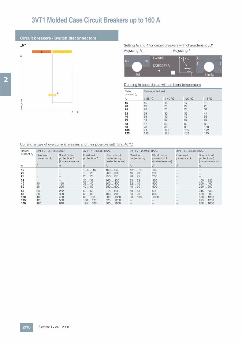
„N“ Setting IR and Ii for circuit breakers with characteristic „D“
Adjusting IR Adjusting Ii
Derating in accordance with ambient temperature
Current ranges of overcurrent releases and their possible setting at 40 °C
NSO0_00216
t
I
L I
IiRated current In
Permissible load
A + 55 °C + 40 °C +20 °C -15 °C
16 15 16 17 1920 19 20 22 2525 23 25 28 31
32 29 32 36 4140 38 40 45 5350 48 50 56 66
63 57 63 69 8380 73 80 88 100100 91 100 105 122125 110 125 132 145
Rated current In
3VT1 7..-2DA36-0AA0 3VT1 7..-2DC36-0AA0 3VT1 7..-2DM36-0AA0 3VT1 7..-2DB36-0AA0
Overload protection Ir
Short circuit protection Ii (instantaneous)
Overload protection Ir
Short circuit protection Ii (instantaneous)
Overload protection Ir
Short circuit protection Ii (instantaneous)
Overload protection Ir
Short circuit protection Ii (instantaneous)
A A A A A A A A A
16 -- -- 12,5 ... 16 160 ... 240 12,5 ... 16 160 -- --20 -- -- 16 ... 20 200 ... 300 16 ... 20 200 -- --25 -- -- 20 ... 25 250 ... 375 20 ... 25 250 -- --
32 -- -- 25 ... 32 160 ... 320 25 ... 32 320 -- 160 ... 32040 40 160 32 ... 40 200 ... 400 32 ... 40 400 -- 200 ... 40050 50 200 40 ... 50 250 ... 500 40 ... 50 500 -- 250 ... 500
63 63 252 50 ... 63 315 ... 630 50 ... 63 630 -- 315 ... 63080 80 320 63 ... 80 400 ... 800 63 ... 80 800 -- 400 ... 800100 100 400 80 ... 100 500 ... 1000 80 ... 100 1000 -- 500 ... 1000125 125 500 100 ... 125 625 ... 1250 -- -- -- 625 ... 1250160 160 640 125 ... 160 800 ... 1600 -- -- -- 800 ... 1600

3VT1 Molded Case Circuit Breakers up to 160 A
Circuit breakers · Switch disconnectors
2/17Siemens LV 36 · 2008
2
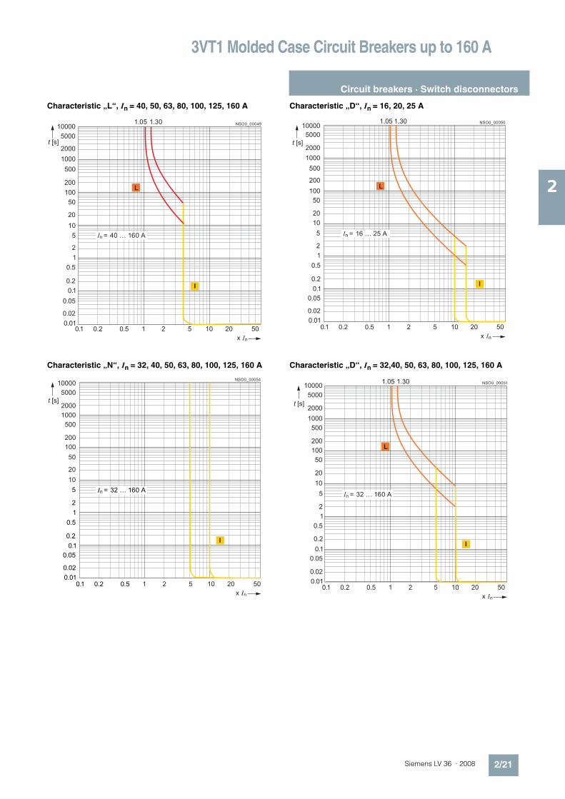
Characteristic „L“, In = 40, 50, 63, 80, 100, 125, 160 A
Characteristic „D“, In = 16, 20, 25 A
Characteristic „D“, In = 32, 40, 50, 63, 80, 100, 125, 160 A
Characteristic „M“, In = 16, 20, 25 A
NSO0_00049
20
200
2000
50
500
5000
10
100
1000
10000
t [s]
1 2 5 20 5010
L
I
0.1 0.2 0.5
In = 40 … 160 A
1.05 1.30
x In
0.01
0.02
0.05
0.1
0.2
0.5
1
2
5
L
NSO0_00050
20
200
2000
50
500
5000
10
100
1000
10000
t [s]
1 2 5 20 50100.1 0.2 0.5
x In
0.01
0.02
0.05
0.1
0.2
0.5
1
2
5
1.05 1.30
L
In = 16 … 25 A
I
NSO0_00051
20
200
2000
50
500
5000
10
5
100
1000
10000
t [s]
1 2 5 20 50100.1 0.2 0.5
x In
0.01
0.02
0.05
0.1
0.2
0.5
1
2
1.05 1.30
In = 32 … 160 A
I
L
NSO0_00052
20
200
2000
50
500
5000
10
100
1000
10000
t [s]
1 2 5 20 50100.1 0.2 0.5
x In
0.01
0.02
0.05
0.1
0.2
0.5
1
2
5
1.00 1.20
L
I
In = 16 … 25 A

3VT1 Molded Case Circuit Breakers up to 160 A
Circuit breakers · Switch disconnectors
2/18 Siemens LV 36 · 2008
2
Characteristic „M“, In = 32, 40, 50, 63, 80, 100 A
Characteristic „N“, In = 32, 40, 50, 63, 80, 100, 125, 160 A
NSO0_00053
20
200
2000
50
500
5000
10
100
1000
10000
t [s]
x In
0.01
0.02
0.05
0.1
0.2
0.5
1
2
5
1.00 1.20
1 2 5 20 50100.1 0.2 0.5
I
In = 32 … 100 A
L
20
200
2000
50
500
5000
10
100
1000
10000
t [s]
x In
0.01
0.02
0.05
0.1
0.2
0.5
1
2
5
1 2 5 20 50100.1 0.2 0.5
NSO0_00054
I
In = 32 … 160 A

3VT1 Molded Case Circuit Breakers up to 160 A
Circuit breakers · Switch disconnectors
2/19Siemens LV 36 · 2008
2
Overcurrent releases, 4-pole version
The overcurrent release is an integral part of the circuit breaker.
It is not possible to deinstall or exchange the releases.4-pole circuit breakers are manufactured in the following versions:
• 3P+N (three poles protected, N-pole unprotected)• 4P (all four poles protected)
The permissible load of the N-pole is 100% In.
Tripping characteristics
The circuit breakers are delivered with three types of tripping characteristics designated by the following letters:
„L“ - lines Protection of lines with low starting current
„D“ - distribution Protection of lines and transformers
„N“ - short-circuit Protection against short circuit only
• 3VT1 Circuit breakers with characteristic „L“ have a fixed value of rated current I (without In control). The circuit break-ers are manufactured with In values of standard current range 40 ... 160 A, see „Ranges of overcurrent release and their possible setting“. The Short-circuit release has a fixed setting to 4 x In.
• 3VT1 circuit breakers with characteristic „D“ can be set to a reduced current in the range of approx. 0.75 ... 1 In. The circuit breakers are manufactured with In values within a standard current range of 16 ... 160 A. Setting values are given in the table on page 2/20.
• 3VT1 Circuit breakers with characteristic „N“ have only a short circuit release. They are manufactured with circuit breaker val-ues within a standard current range of 32 ... 160 A. The Short circuit release is adjustable. The values are given in the table on page 2/20.
The type designation for the circuit breakers is set according to the requested rated current and protection characteris-tics.
For example.: Protection of a circuit with In = 40 A.The order No. designation will be 3VT1 704-2EC46-0AA0.
Setting of tripping characteristics
• Dependent release (thermal) L (for circuit breakers with characteristics “D” and “M”). The dependent release for over-load protection Ir (instantaneous), is adjusted in a continuous range using the Ir adjustment dial on the overload release. The Ir adjustment range is 0.75 ... 1 In.
• Independent instantaneous release (short-circuit relase) I (for circuit breakers with characteristics “D” and “N”). With an independent instantaneous release (value of the short circuit current Ii), adjustment is possible within a continuous range. All values are given in the table on page 2/20.
Setting of tripping characteristics
Circuit breakers with characteristic
„L“
„D“
„N“
NSO0_00502
t
I
L I
NSO0_00500
t
I
L I
Ir
Ii
NSO0_00216
t
I
L I
Ii

3VT1 Molded Case Circuit Breakers up to 160 A
Circuit breakers · Switch disconnectors
2/20 Siemens LV 36 · 2008
2
Setting IR and Ii for circuit breakers with characteristic „D“
Setting IR Setting Ii
Derating in accordance with ambient temperature
Current ranges of overcurrent releases and their possible setting at 40 °C
Rated current In
Permissible load
A + 55 °C + 40 °C +20 °C -15 °C
16 15 16 17 1920 19 20 22 2525 23 25 28 31
32 29 32 36 4140 38 40 45 5350 48 50 56 66
63 57 63 69 8380 73 80 88 100100 91 100 105 122
125 110 125 132 145160 145 160 168 175
Rated current In
3VT1 7..-2EA46-0AA0 3VT1 7..-2EC46-0AA0 3VT1 7..-2EB46-0AA0
Overload protection Ir Short circuit protection Ii (instantaneous)
Overload protection Ir Short circuit protection Ii (instantaneous)
Overload protection Ir Short circuit protection Ii (instantaneous)
A A A A A A A
16 - -- 12,5 ... 16 160 ... 240 - -20 - -- 16 ... 20 200 ... 300 - -25 - -- 20 ... 25 250 ... 375 - -
32 - -- 25 ... 32 160 ... 320 - 160 ... 32040 40 160 32 ... 40 200 ... 400 - 200 ... 40050 50 200 40 ... 50 250 ... 500 - 250 ... 500
63 63 252 50 ... 63 315 ... 630 - 315 ... 63080 80 320 63 ... 80 400 ... 800 - 400 ... 800100 100 400 80 ... 100 500 ... 1000 - 500 ... 1000
125 125 500 100 ... 125 625 ... 1250 - 625 ... 1250160 160 640 125 ... 160 800 ... 1600 - 800 ... 1600
3VT1 Molded Case Circuit Breakers up to 160 A
Circuit breakers · Switch disconnectors
2/21Siemens LV 36 · 2008
2
Characteristic „L“, In = 40, 50, 63, 80, 100, 125, 160 A
Characteristic „N“, In = 32, 40, 50, 63, 80, 100, 125, 160 A
Characteristic „D“, In = 16, 20, 25 A
Characteristic „D“, In = 32,40, 50, 63, 80, 100, 125, 160 A
NSO0_00049
20
200
2000
50
500
5000
10
100
1000
10000
t [s]
1 2 5 20 5010
L
I
0.1 0.2 0.5
In = 40 … 160 A
1.05 1.30
x In
0.01
0.02
0.05
0.1
0.2
0.5
1
2
5
20
200
2000
50
500
5000
10
100
1000
10000
t [s]
x In
0.01
0.02
0.05
0.1
0.2
0.5
1
2
5
1 2 5 20 50100.1 0.2 0.5
NSO0_00054
I
In = 32 … 160 A
L
NSO0_00050
20
200
2000
50
500
5000
10
100
1000
10000
t [s]
1 2 5 20 50100.1 0.2 0.5
x In
0.01
0.02
0.05
0.1
0.2
0.5
1
2
5
1.05 1.30
L
In = 16 … 25 A
I
NSO0_00051
20
200
2000
50
500
5000
10
5
100
1000
10000
t [s]
1 2 5 20 50100.1 0.2 0.5
x In
0.01
0.02
0.05
0.1
0.2
0.5
1
2
1.05 1.30
In = 32 … 160 A
I
L

3VT1 Molded Case Circuit Breakers up to 160 AAccessories and Components
Auxiliary switches
2/22 Siemens LV 36 · 2008
2
n Overview
Auxiliary switches
Auxiliary and alarm switches
Function, name and location of switches according to type designation
1) In the accessory compartment 1, a 3VT9 100-2AB10 auxiliary switch and 3VT9 100-2AH10 signal switch cannot be used simultaneously.
2) When one of accessory compartments 4, 5 or 6 is already in use for auxil-iary switches, a shunt release or undervoltage release cannot be fitted additionally.
Location of switches in accessory compartments
Location of accessory compartments in a 3-pole 3VT1 circuit breaker/switch disconnector.
Location of accessory compartments in a 4-pole 3VT1 circuit breaker/switch disconnector.
When using one of the accessory compartments 4, 5 or 6, neither a shunt release nor an undervoltage release cannot be fitted.
Order No. Type Switch location Switch function
3VT9 100-2AB10 3VT9 100-2AB20
Auxiliaryswitch
Accessory compartment 11), 2, 3, 4, 5, 62)
Signaling of the state of the main contact of the circuit breaker/ switch dis-connector
3VT9 100-2AH10 3VT9 100-2AH20
Alarm switch
Accessory compartment 11)
Signal in the event of tripping of the cir-cuit breaker by the overcurrent release
3VT1 Molded Case Circuit Breakers up to 160 AAccessories and Components
Auxiliary switches
2/23Siemens LV 36 · 2008
2
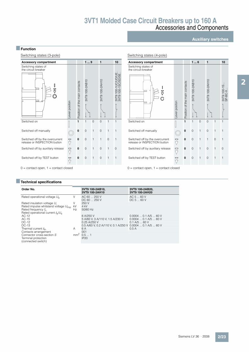
n Function
Switching states (3-pole)
0 = contact open, 1 = contact closed
Switching states (4-pole)
0 = contact open, 1 = contact closed
n Technical specifications
Accessory compartment 1 ... 9 1 10
Switching states of the circuit breaker
Le
ve
r p
osito
n
Po
sitio
n o
f th
e m
ain
co
nta
cts
3V
T9
10
0-2
AB
10
3V
T9
10
0-2
AH
10
3V
T9
10
0-1
UC
/UD
/UE
..3
VT9
10
0-1
SC
/SD
/SE
..Switched on 1 1 0 0 1 1
Switched off manually 0 0 1 0 1 1
Switched off by the overcurrent release or INSPECTION button
0 0 1 1 0 1
Switched off by auxiliary release 0 0 1 0 1 0
Switched off by TEST button 0 0 1 0 1 1
Accessory compartment 1 ... 6 1 10
Switching states of the circuit-breaker
Le
ve
r p
osito
n
Po
sitio
n o
f th
e m
ain
co
nta
cts
3V
T9
10
0-2
AB
10
3V
T9
10
0-2
AH
10
3V
T9
10
0-1
S...
SP
-BC
-X..
.
Switched on 1 1 0 0 1 1
Switched off manually 0 0 1 0 1 1
Switched off by the overcurrent release or INSPECTION button
0 0 1 1 0 1
Switched off by auxiliary release 0 0 1 0 1 0
Switched off by TEST button 0 0 1 0 1 1
Order No. 3VT9 100-2AB10, 3VT9 100-2AH10
3VT9 100-2AB20, 3VT9 100-2AH20
Rated operational voltage Ue V AC 60 ... 250 VDC 60 ... 250 V
AC 5 ... 60 V DC 5 ... 60 V
Rated insulation voltage Ui V 250 VRated impulse whitstand voltage Uimp kV 4 kVRated frequency fn Hz 50/60 HzRated operational current Ie/UeAC-12 6 A/250 V 0.0004 ... 0.1 A/5 ... 60 VAC-15 5 A/60 V, 3 A/110 V, 1.5 A/230 V 0.0004 ... 0.1 A/5 ... 60 VDC-12 0.25 A/250 V 0.1 A/5 ... 60 VDC-13 0.5 A/60 V, 0.2 A/110 V, 0.1 A/250 V 0.0004 ... 0.1 A/5 ... 60 VThermal current Ith A 6 A 0.5 AContacts arrangement 001Connector cross-section S mm2 0.5 ... 1 Terminal protection (connected switch)
IP20

3VT1 Molded Case Circuit Breakers up to 160 AAccessories and Components
Auxiliary releases
2/24 Siemens LV 36 · 2008
2
n Design
Auxiliary releases
Shunt release Undervoltage release
Location of auxiliary releases
Auxiliary releases in compartment 10
Type designation according to the rated operational voltage
Type designation according to the rated operational voltage
The specific rated operational voltage of the shunt release is set by jumpers directly on the release. The standard setting by the manufacturer is always to the value corresponding to the type designation.
Schematics
Shunt release Undervoltage release
n Technical specifications
Ue Order No.
AC/DC 24/48 V 3VT9 100-1SC00AC 110/230 V, DC 110/220 V 3VT9 100-1SD00AC 230/400 V, DC 220 V 3VT9 100-1SE00
Ue Order No.
AC/DC 24/48 V 3VT9 100-1UC00AC 110/230 V /DC 110/220 V 3VT9 100-1UD00AC 230/400 V /DC 220 V 3VT9 100-1UE00
B1
U
B2
10.Y2
N-
3VT9 100-1S.0
L+
NSO0_00055
10.Y1
A1
U<
A2
10.Y2
N-
3VT9 100-1U.0
L+
NSO0_00056
10.Y1
Order No. 3VT9 100-1S.00
Rated operational voltage Ue AC 24/48/110/230/400 V DC 24/48/110/220 V
Rated frequency fn 50/60 HzInput power at 1.1 Ue• AC 2 VA• DC 2 WCharacteristics U #!0.7 Ue circuit breaker must tripTime before switching off 15 msLoading time $
Connection cross-section S 0,5 ... 1 mm2
Terminal protection (connected release)
IP20
Location in accessory compartment no. 10
SIGNAL SWITCH - signals switching off by shunt trip
Rated operational voltage Ue AC 230 V Rated insulation voltage Ui 250 VRated impulse withstand voltage Uimp 4 kVRated frequency fn 50/60 HzRated operational current Ie/Ue 2 A/AC 230 V Thermal current Ith 6 AContact arrangement 01
Order No. 3VT9 100-1U.00
Rated operational voltage Ue AC 24/48/110/230/400 V DC 24/48/110/220 V
Rated frequency fn 50/60 HzInput power at 1.1 Ue• AC 2 VA• DC 2 WCharacteristic U % 0.35 Ue circuit breaker can be
switched on U #!0.85 Ue circuit breaker must trip
Time before switching off 15 msLoading time $
Connector cross-section S 0.5 ... 1 mm2
Terminal protection (connected release)
IP20
Location in accessory compartment no. 10
SIGNAL SWITCH - signals switching off of the undervoltage
Rated operational voltage Ue AC 230 V Rated insulation voltage Ui 250 VRated impulse withstand voltage Uimp 4 kVRated frequency fn 50/60 HzRated operational current Ie/Ue 2 A/AC 230 V Thermal current Ith 6 AContact arrangement 01
3VT1 Molded Case Circuit Breakers up to 160 AAccessories and Components
Manual operating mechanisms
2/25Siemens LV 36 · 2008
2
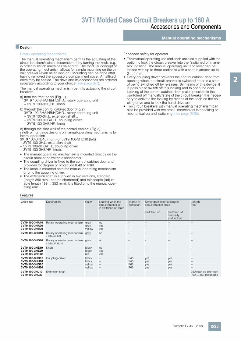
n Design
Rotary operating mechanisms
The manual operating mechanism permits the actuating of the circuit breakers/switch disconnectors by turning the knob, e.g. in order to switch machines on and off. The modular concept of the operating mechanism allows for simple mounting on the cir-cuit breaker (even as an add-on). Mounting can be done after having removed the accessory compartment cover. An affixed drive may be sealed. The drive and its accessories are ordered separately according to your choice (see page 2/7).
The manual operating mechanism permits actuating the circuit breaker:
a) from the front panel (Fig. 1)3VT9 100-3HA/HB/HC/HD.. rotary operating unit + 3VT9 100-3HE/HF.. knob
b) through the control cabinet door (Fig.2)3VT9 100-3HA/HB/HC/HD.. rotary operating unit + 3VT9 100-3HJ.. extension shaft .. + 3VT9 100-3HG/HH.. coupling driver + 3VT9 100-3HE/HF.. knob
c) through the side wall of the control cabinet (Fig.3) in left- or right-side designs of manual operating mechanisms for lateral operation 3VT9 100-3HD10 (right) or 3VT9 100-3HC10 (left) + 3VT9 100-3HJ.. extension shaft + 3VT9 100-3HG/HH.. coupling driver + 3VT9 100-3HE/HF.. knob.
• The manual operating mechanism is mounted directly on the circuit breaker or switch disconnector.
• The coupling driver is fixed to the control cabinet door and provides for degree of protection IP40 or IP66.
• The knob is mounted onto the manual operating mechanism or onto the coupling driver.
• The extension shaft is supplied in two versions, standard (length 350 mm - can be shortened) and telescopic (adjust-able length 199 ... 352 mm). It is fitted onto the manual oper-ating unit.
Enhanced safety for operator
• The manual operating unit and knob are also supplied with the option to lock the circuit breaker into the “switched off manu-ally” position. The manual operating unit and lever can be locked with up to three padlocks with a shaft diameter up to 3 ... 4 mm.
• Every coupling driver prevents the control cabinet door from opening when the circuit breaker is switched on or in a state of being switched off by releases. By means of this device, it is possible to switch off this locking and to open the door. Locking of the control cabinet door is also possible in the „switched off manually“state of the circuit breaker. It is neces-sary to activate the locking by means of the knob on the cou-pling drive and to lock the hand drive arm.
• Two circuit breakers with manual operating mechanism can also be provided with reciprocal mechanical interlocking or mechanical parallel switching (see page 2/26).
Features
Order No. Description Color Locking while the circuit breaker is in switched off state
Degree of Protection
Switchgear door locking in circuit breaker state
Length mm
switched on switched off manually and locked
3VT9 100-3HA10 Rotary operating mechanism gray no -- -- -- --3VT9 100-3HA20 gray yes -- -- -- --3VT9 100-3HB20 yellow yes -- -- -- --
3VT9 100-3HC10 Rotary operating mechanism - lateral, left
grey no -- - -- --
3VT9 100-3HD10 Rotary operating mechanism - lateral, right
grey no -- - -- --
3VT9 100-3HE10 Knob black no -- -- -- --3VT9 100-3HE20 black yes -- -- -- --3VT9 100-3HF20 red yes -- -- -- --
3VT9 100-3HG10 Coupling driver black -- IP40 yes yes --3VT9 100-3HH10 black -- IP40 yes yes --3VT9 100-3HG20 yellow -- IP66 yes yes --3VT9 100-3HH20 yellow -- IP66 yes yes --
3VT9 100-3HJ10 Extension shaft -- -- -- -- -- 350 (can be shorted)3VT9 100-3HJ20 -- -- -- -- -- 199 ... 352 telescopic

3VT1 Molded Case Circuit Breakers up to 160 AAccessories and Components
Manual operating mechanisms
2/26 Siemens LV 36 · 2008
2
Mechanical interlocks and mechanical interlocks for parallel switching
3VT9 100-8LA00 mechanical interlocking
The mechanical interlocks are for the mechanical interlocking of two circuit breakers so that they cannot be tripped simulta-neously, but always just individually. Both circuit breakers may be switched off simultaneously. Interlocking can be used be-tween two 3VT1 circuit breakers. Each circuit breaker must be furnished with a manual operating mechanism – at least one with a manual operaitng unit and a knob, (see page 2/25). In order to use the interlocking, it is absolutely necessary to comply with the dimensions shown in the figure and given in the table.
Arrangement of circuit breakers/switch disconnectors with 3VT9 100-8LA00 mechanical interlocks
3VT9 100-8LB00 mechanical interlocks for parallel switching
Mechanical interlocks for parallel switching are for simultaneous switching of two circuit breakers. Parallel switching can be used between two 3VT1 circuit breakers. Each circuit breaker must be furnished with a manual operating unit and at least one with a knob (see page 2/25). In order to use parallel switching, it is ab-solutely necessary to comply with the dimensions shown in the figure and given in the table.
Arrangement of circuit breakers/switch disconnectors with 3VT9 100-8LB00 mechanical interlocks for parallel switching
Dimensions mm
X 87.5 or 100L 94.5 or 106
NSO0_00057
L
X
NSO0_00059
12.5 or 25
Dimensions mm
X 75 or 87.5 or 100L L
NSO0_00058
X
L
NSO0_00060
0 or 12.5 or 25
3VT1 Molded Case Circuit Breakers up to 160 AAccessories and Components
Motorized operating mechanisms
2/27Siemens LV 36 · 2008
2
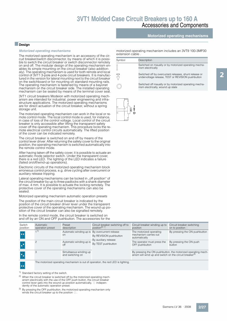
n Design
Motorized operating mechanisms
The motorized operating mechanism is an accessory of the cir-cuit breaker/switch disconnector, by means of which it is possi-ble to switch the circuit breaker or switch disconnector remotely on and off. The modular design of the operating mechanism en-ables its simple mounting on the circuit breaker (also addition-aly). The operating mechanism is used for both remote and local control of 3VT1 3-pole and 4-pole circuit breakers. It is manufac-tured in the version for lateral mounting next to the circuit breaker on the switchboard or for mounting on standard mounting rails. The operating mechanism is fastened by means of a bayonet mechanism on the circuit breaker side. The installed operating mechanism can be sealed by means of the terminal cover seal.
3VT1 circuit breakers Modeion with motorized operating mech-anism are intended for industrial, power engineering and infra-structure applications. The motorized operating mechanisms are for direct actuation of the circuit breaker, without a spring storage unit.
The motorized operating mechanism can work in the local or re-mote control mode. The local control mode is used, for instance, in case of loss of the control voltage. Local control of the circuit breaker is only accessible after lifting the transparent safety cover off the operating mechanism. This procedure locks the re-mote electrical control circuits automatically. The lifted position of the cover can be indicated remotely.
The circuit breaker is switched on and off by means of the control lever driver. After returning the safety cover to the original position, the operating mechanism is switched automatically into the remote control mode.
After having taken off the safety cover, it is possible to actuate anautomatic mode selector switch. Under the transparent cover, there is a red LED. The lighting of the LED indicates a failure (failed on/off/wind-up operations).
Electronic circuits of the motorized operating mechanism block erroneous control process, e.g. drive cycling after overcurrent or auxiliary release tripping.
Lateral operating mechanisms can be locked in „off position“ of the circuit breaker by up to three padlocks with a shank diameter of max. 4 mm. It is possible to actuate the locking remotely. The protective cover of the operating mechanisms can also be sealed.
Motorized operating mechanism automatic operation presets
The position of the main circuit breaker is indicated by the position of the circuit breaker driver lever under the transparent protective cover of the operating mechanism. The wound up po-sition of the circuit breaker can also be signalled remotely.
In the remote control mode, the circuit breaker is switched on and off by an ON and OFF pushbutton. The accessories for the
motorized operating mechanism includes an 3VT9 100-3MF00 extension cable .
1) Standard factory setting of the switch.2) When the circuit breaker is switched off by the motorized operating mech-
anism electrically with the use of the OFF push button, the circuit breaker control lever gets into the wound up position automatically, indepen-dently of the automatic operation preset.
3) By pressing the OFF pushbutton, the motorized operaitng mechanism only winds the circuit breaker up to the position .
Symbol Description
Switched on maually or by motorized operating mecha-nism electrically
Switched off by overcurrent releases, shunt release or undervoltage release, TEST or REVISION pushbutton
Switched off maually or by motorized operating mecha-nism electrically, wound up state
Switch position
Automatic operation preset
Preset description
Circuit breaker switching off to postion2)
Circuit breaker winding up to position
Circuit breaker switching on to position
11) Automatic winding up is on
By overcurrent release
By REVISION pushbutton
By auxiliary release
By TEST pushbutton
The motorized operating mechanism carries outautomatically
By pressing the ON pushbutton
2 Automatic winding up is off
The operator must press the OFF pushbutton
By pressing the ON push button
3 Simultaeous winding up and switching on
By pressing the ON pushbutton, the motorized operating mech-anism will wind up and switch on the circuit breaker3)
The motorized operating mechanism is out of operation, the red LED is lighting.
N0
1 2
N0
1 2
N0
1 2
N0
1 2
3VT1 Molded Case Circuit Breakers up to 160 AAccessories and Components
Motorized operating mechanisms
2/28 Siemens LV 36 · 2008
2
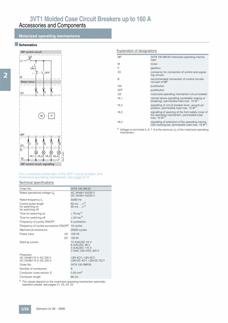
n Schematics
For a complete schematic of the 3VT1 circuit breaker with motorized operating mechanism, see page 2/14.
Technical specifications
1) The values depend on the motorized operating mechanism automatic operation preset, see pages 21, 23, 24, 25.
Explanation of designations
1) Voltage on terminals 5, 6, 7, 8 is the same as Un of the motorized operating mechanism.
Order No. 3VT9 100-3M.00
Rated operational voltage Ue AC 24/48/110/230 VDC 24/48/110/220 V
Rated frequency fn 50/60 Hz
Control pulse lengthfor switching onfor switching off
60 ms ... 1)
60 ms ... 1)
Time for switching on ! 70 ms1)
Time for switching off < 50 ms1)
Frequency of cycles ON/OFF 5 cycles/min
Frequency of cycles-successive ON/OFF 10 cycles
Mechanical endurance 20000 cycles
Power input AC 100 VA
DC 100 W
Starting current 12 A/AC/DC 24 V 6 A/AC/DC 48 V4 A/AC/DC 110 V2 A/AC 230 V/DC 220 V
Protection AC 24/48/110 V; AC 230 VDC 24/48/110 V; DC 220 V
LSN 4C/1; LSN 2C/1LSN-DC 4C/1; LSN-DC 2C/1
Order No. 3VT9 100-3MF00
Number of conductors 8
Conductor cross section S 0.35 mm2
Conductor length 60 cm
L+
Q3
X3
MP
X32
4
5
3
6
1
7 8
M
NSO0_00061
B
P
HL1 HL2 HL3 HL4
B
N-
MP control circuit
ON
OFF
Motor drive
MP control circuit, signalling
MP 3VT9 100-3M.00 motorized oeprating mecha-nism
M motor
P gearbox
X3 connector for connection of control and signal-ing circuits
B recommended connection of control circuits- not part of MP
ON pushbutton
OFF pushbutton
Q3 motorized operating mechanism circuit breaker
HL1 remote failure signalling (unreliable making or breaking), permissible load max. 10 W1)
HL2 signalling of circuit breaker lever „wound up“ position, permissible load max. 10 W1)
HL3 signalling of opening of the front safety cover of the operating mechanism, permissible load max. 10 W1)
HL4 signalling of extension of the operating mecha-nism locking bar, permissible load max. 10 W1)
3VT1 Molded Case Circuit Breakers up to 160 AAccessories and Components
Motorized operating mechanisms
2/29Siemens LV 36 · 2008
2
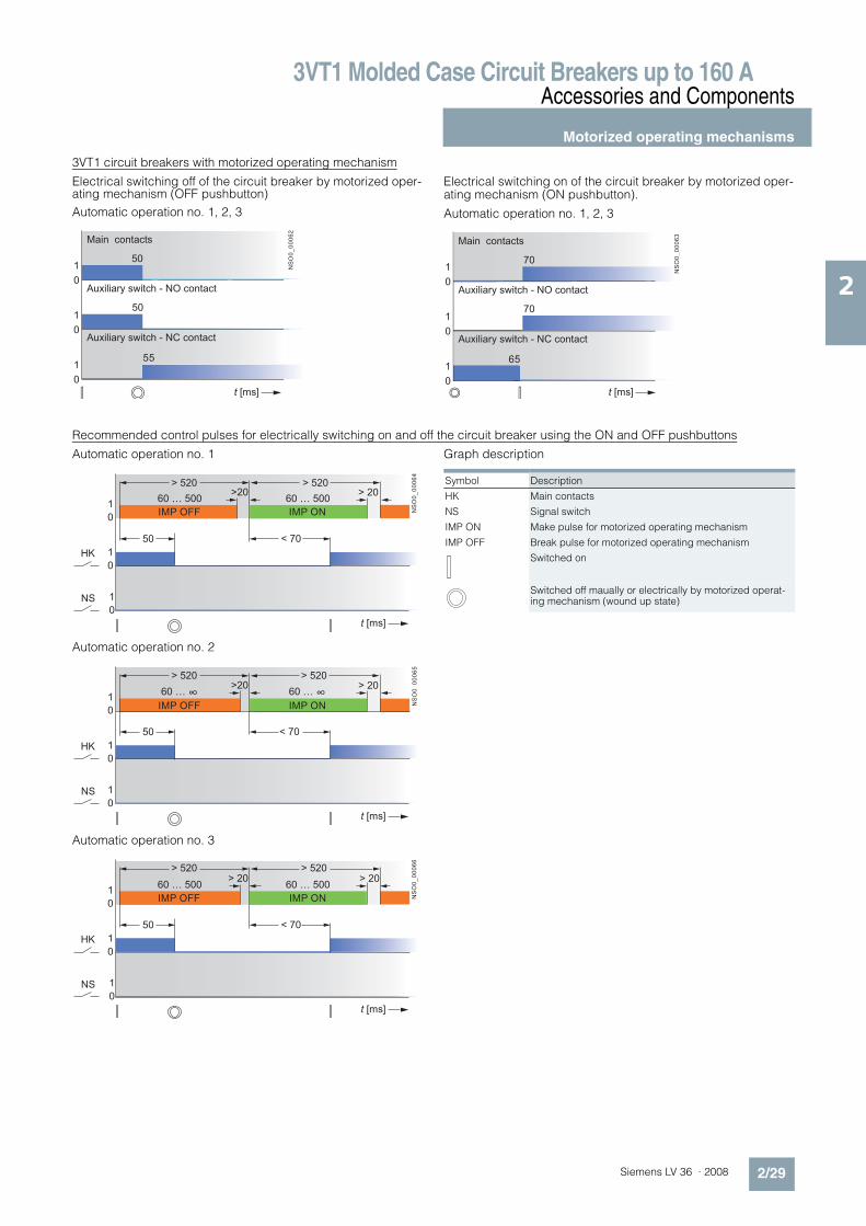
3VT1 circuit breakers with motorized operating mechanism
Electrical switching off of the circuit breaker by motorized oper-ating mechanism (OFF pushbutton)
Automatic operation no. 1, 2, 3
Electrical switching on of the circuit breaker by motorized oper-ating mechanism (ON pushbutton).
Automatic operation no. 1, 2, 3
Recommended control pulses for electrically switching on and off the circuit breaker using the ON and OFF pushbuttons
Automatic operation no. 1
Automatic operation no. 2
Automatic operation no. 3
Graph description
0
1
0
1
0
1
t [ms]
55
NSO0_00062
50
50
Auxiliary switch - NC contact
Auxiliary switch - NO contact
Main contacts
0
1
0
1
0
1
t [ms]
65
70
70
NSO0_00063
Auxiliary switch - NC contact
Auxiliary switch - NO contact
Main contacts
NSO0_00064
t [ms]
1
0
1
0
1
0
HK
NS
60 … 500
50
60 … 500>20
> 520 > 520> 20
< 70
IMP OFF IMP ON
NSO0_00065
t [ms]
1
0
1
0
1
0
HK
NS
60 … ∞
50
60 … ∞>20
> 520 > 520> 20
< 70
IMP OFF IMP ON
NSO0_00066
t [ms]
1
0
1
0
1
0
HK
NS
60 … 500
50
60 … 500> 20
> 520 > 520> 20
< 70
IMP ONIMP OFF
Symbol Description
HK Main contacts
NS Signal switch
IMP ON Make pulse for motorized operating mechanism
IMP OFF Break pulse for motorized operating mechanism
Switched on
Switched off maually or electrically by motorized operat-ing mechanism (wound up state)

3VT1 Molded Case Circuit Breakers up to 160 AAccessories and Components
Motorized operating mechanisms
2/30 Siemens LV 36 · 2008
2
Circuit breaker switching off by overcurrent release or INSPECTION pushbutton
Automatic operation no. 1
Automatic operation no. 2
Automatic operation no. 3
10
10
10
15
5
0
1
0
1
0
1
0
1
0
1
1085
1080NSO0_00067
t [ms]
2
4
6
1
3
5
3.4 3.3
3.2 3.1
2.4 2.3
2.2 2.1
Main contacts
Auxiliary switch - NO contact
Auxiliary switch - NC contact
Signal switch - NO contact
Signal switch - NC contact
accessory
compartment
3
accessory
compartment
2
10
10
10
15
5
0
1
0
1
0
1
0
1
0
1 NSO0_00068
t [ms]
2
4
6
1
3
5
3.4 3.3
3.2 3.1
2.4 2.3
2.2 2.1
Main contacts
Auxiliary switch - NO contact
Auxiliary switch - NC contact
Signal switch - No contact
Signal switch - NC contact
accessory
compartment
3
accessory
compartment
2
10
10
10
15
5
0
1
0
1
0
1
0
1
0
1 NSO0_00068
t [ms]
2
4
6
1
3
5
3.4 3.3
3.2 3.1
2.4 2.3
2.2 2.1
Main contacts
Auxiliary switch - NO contact
Auxiliary switch - NC contact
Signal switch - No contact
Signal switch - NC contact
accessory
compartment
3
accessory
compartment
2
3VT1 Molded Case Circuit Breakers up to 160 AAccessories and Components
Motorized operating mechanisms
2/31Siemens LV 36 · 2008
2
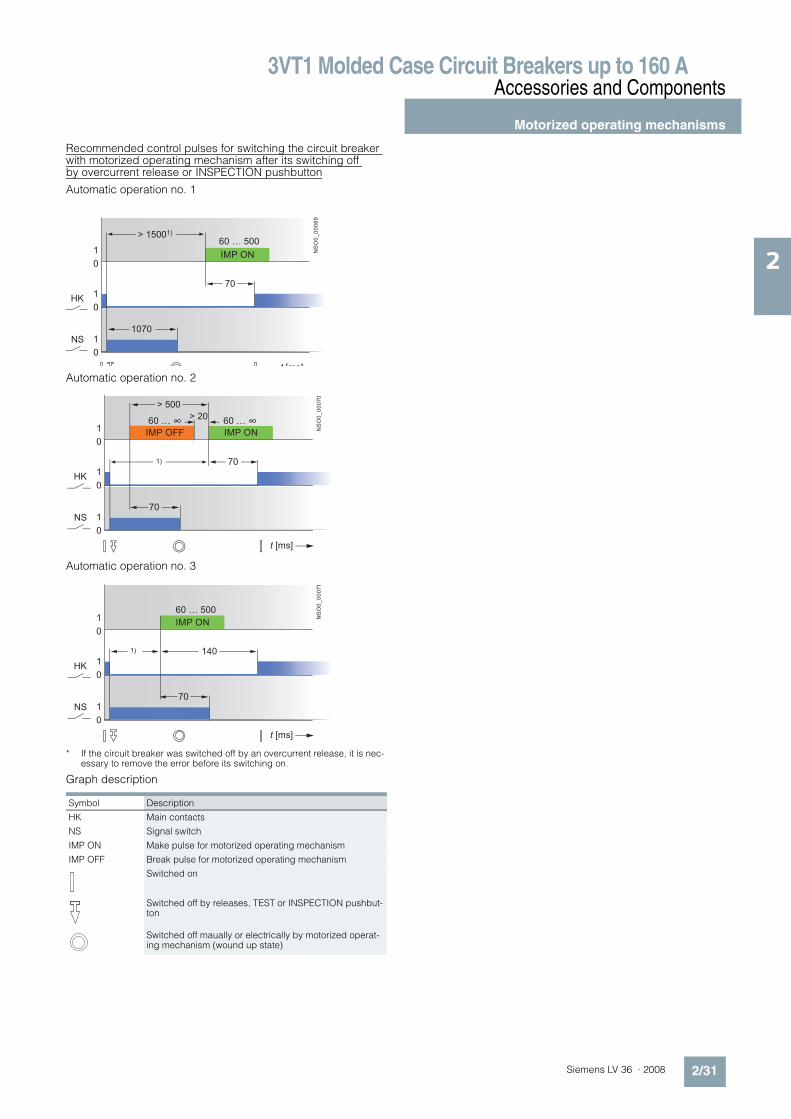
Recommended control pulses for switching the circuit breaker with motorized operating mechanism after its switching off by overcurrent release or INSPECTION pushbutton
Automatic operation no. 1
Automatic operation no. 2
Automatic operation no. 3
* If the circuit breaker was switched off by an overcurrent release, it is nec-essary to remove the error before its switching on.
Graph description
Symbol Description
HK Main contacts
NS Signal switch
IMP ON Make pulse for motorized operating mechanism
IMP OFF Break pulse for motorized operating mechanism
Switched on
Switched off by releases, TEST or INSPECTION pushbut-ton
Switched off maually or electrically by motorized operat-ing mechanism (wound up state)
1
0
1
0
1
0
1070
70
NSO0_00069
t [ms]
HK
NS
60 … 500> 15001)
IMP ON
60 … ∞1
0
1
0
1
0
70
70
NSO0_00070
t [ms]
HK
NS
60 … ∞
1)
> 500
> 20
IMP OFF IMP ON
1
0
1
0
1
0
70
140
60 … 500
NSO0_00071
t [ms]
HK
NS
1)
IMP ON

3VT1 Molded Case Circuit Breakers up to 160 AAccessories and Components
Motorized operating mechanisms
2/32 Siemens LV 36 · 2008
2
Circuit breaker switching off by shunt release, undervoltage release or TEST pushbutton
Automatic operation no. 1
Automatic operation no. 2
Automatic operation no. 3
15
15
20
10
0
1
0
1
0
1
0
1
t [ms]
1085NSO0_00072
2
4
6
1
3
5
3.4 3.3
3.2 3.1
2.4 2.3
accessory
compartment
3
accessory
compart-
ment
2
Main contacts
Auxiliary switch - NO contact
Auxiliary switch - NC contact
signal switch Auxiliary release
15
15
20
10
0
1
0
1
0
1
0
1
t [ms]
NSO0_00073
2
4
6
1
3
5
3.4 3.3
3.2 3.1
2.4 2.3
Main contacts
Auxiliary switch - NO contact
Auxiliary switch - NC contact
signal switch Auxiliary release
accessory
compartment
3
accessory
compart-
ment
2
15
15
20
10
0
1
0
1
0
1
0
1
t [ms]
NSO0_00073
2
4
6
1
3
5
3.4 3.3
3.2 3.1
2.4 2.3
Main contacts
Auxiliary switch - NO contact
Auxiliary switch - NC contact
signal switch Auxiliary release
accessory
compartment
3
accessory
compart-
ment
2
3VT1 Molded Case Circuit Breakers up to 160 AAccessories and Components
Motorized operating mechanisms
2/33Siemens LV 36 · 2008
2
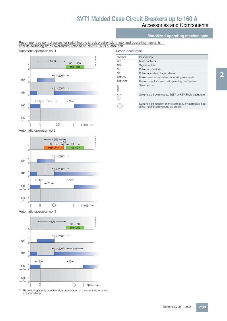
Recommended control pulses for switching the circuit breaker with motorized operating mechanism after its switching off by overcurrent release or INSPECTION pushbutton
Automatic operation no. 1
Automatic operation no.2
Automatic operation no. 3
* Reswitching is only possible after deactivation of the shunt trip or under-voltage release.
Graph description
15 1070
0
1
0
1
0
1
0
1
0
1
t [ms]
NSO0_00074
HK
SP
SV
NS
70
60 … 500
> 2001)
> 2001)
> 1500
IMP ON
15
70
0
1
0
1
0
1
0
1
0
1
t [ms]
NSO0_00075
HK
SP
SV
NS
70
60 … ∞60 … ∞
> 2001)
> 2001)
> 20> 500
IMP ONIMP OFF
15
0
1
0
1
0
1
0
1
0
1 NSO0_00076
t [ms]
HK
SP
SV
NS
70
60 … 500
> 2001) 140
> 2001)
> 500
IMP ON
Symbol Description
HK Main contacts
NS Signal switch
SV Pulse for shunt trip
SP Pulse for undervoltage release
IMP ON Make pulse for motorized operating mechanism
IMP OFF Break pulse for motorized operating mechanism
Switched on
Switched off by releases, TEST or REVISION pushbutton
Switched off maually or by electrically by motorized oper-ating mechanism (wound up state)

3VT1 Molded Case Circuit Breakers up to 160 AAccessories and Components
Motorized operating mechanisms
2/34 Siemens LV 36 · 2008
2
Overcurrent releases
Tripping characteristics: class M
The tripping time of the overcurrent release of 3VT1 circuit break-ers with characteristic M at 7.2 In corresponds to the release class 10, 10 and 20 according to EN 60947-4-1.
Plate of the overcurrent releases with characteristic M
Rated short-circuit ultimate and service breaking capacity of 3-pole 3VT1 circuit breakers in DC circuits
Specifications
1) in reverse connection of the circuit breaker (input terminals 2, 4, 6 and out-put terminals 1, 3, 5), Icu does not change.
Circuit breaker connection for circuits DC 250 V
Delay device
• The delay can be set at three levels (depending on connec-tion)
• The 3VT9 00-1UX00 unit is inteded only for undervoltagereleases with Ue = AC 230 V
Rated current In
Order No. Class
16 3VT1 701-2DM36-0AA0 10A20 3VT1 702-2DM36-0AA0 10A25 3VT1 792-2DM36-0AA0 10A
32 3VT1 703-2DM36-0AA0 1040 3VT1 704-2DM36-0AA0 1050 3VT1 705-2DM36-0AA0 20
63 3VT1 706-2DM36-0AA0 2080 3VT1 708-2DM36-0AA0 20100 3VT1 710-2DM36-0AA0 20
Order No. 3VT1 7..-2DM36-0AA0
Rated operational voltage Ue DC 250 V
Rated ultimate short-circuit breaking capacity1) (rms value)Icu/Ue
25 kA/DC 250 V; "#= max. 5 ms
Rated service short-circuit breaking capacity (rms value) Ics/Ue
13 kA/DC 250 V; "#= max. 5 ms
Utilization category (switching mode) DC-22A
Order No. Description Packing pc
3VT9 00-1UX00 Enables delayed tripping of undervoltage releases of 3VT circuit breakers
1
Circuit breakers Delay
1st level 2nd level 3rd level
s s s
3VT1 1 2 3.2
3VT2, 3VT3 0.6 1.2 1.9
3VT4, 3VT5 0.5 1 1.5
3VT1
3VT2,3VT3
3VT4/5
1 s
0,6 s
0,5 s
1 3 5
U<
2+ 4 6 8
Ue
3VT1
3VT2,3VT3
3VT4/5
2 s
1,2 s
1 s
1 3 5
U<
2+ 4 6 8
Ue
3VT1
3VT2,3VT3
3VT4/5
3,2 s
1,9 s
1,5 s
1 3 5
U<
2+ 4 6 8
Ue
NSO0_00077
STOP STOP STOP

3VT1 Molded Case Circuit Breakers up to 160 A
Project planning aids
2/35Siemens LV 36 · 2008
2
n Dimensional drawings
Phase barriers and terminal covers
3-pole version Fixed-mounted version
• Front connection- Terminals 1, 3, 5
3VT9 100-8CE30 phase barriers or 3VT9 100-8CA30 termi-nal covers have to be used (when using 3VT9 100-4TF30 connection sets for connecting circuit breakers/switch dis-connectors, the terminal cover is included in the connecting set).
- Terminals 2, 4, 6 3VT9 100-8CE30 phase barriers or 3VT9 100-8CA30 termi-nal covers have to be used if the circuit breaker/switch dis-connector is connected to the power supply using terminals 2, 4, 6 (when using 3VT9 100-4TF30 connection sets for con-necting circuit breaker/switch disconnector, the terminal cover is included in the connecting set).
• Rear connection- phase barriers and covers must be used.
H
>15
Reference Size
mm
A 50 minimum distance between the circuit breaker/switch dis-connector and uninsulated earthed wall (applicable for connections using insulated conductors, cables, flexibars or with rear connection)
A1 100 minimum insulation length of bare conductors (using 3VT9 100-8CE30 phase barriers from 50 mm to max. 100 mm, or by adding additional insulation for the conductors with barriers to obtain at least A1 value)
A2 150 minimum distance:• between circuit breaker/switch disconnector and uninsu-
lated earthed wall (applicable for uninsulated conduc-tors and busbars)
• between circuit breaker/switch disconnector and busbar• between two circuit breakers/switch disconnectors situ-
ated vertically above one another• between uninsulated connections of two circuit
breakers/switch disconnectors above one another
C, D, E, F, G
30 minimum distance between the circuit breaker/switch disconnector and uninsulated earthed wall
H minimum distance between uninsulated conductors
NS
O0
_0
0012
100
TEST
OFF
ON
TEST
OFF
ON
TEST
OFF
ON
H = 30
130
B = 20
A =
50 A
1 =
100
A2 =
150
B = 2075 75 100 B = 20
E = 70 G = 40
F = 0 G = 0
11
1 3VT9 100-8CE30

3VT1 Molded Case Circuit Breakers up to 160 A
Project planning aids
2/36 Siemens LV 36 · 2008
2
4-pole version
Fixed-mounted version
• Front connection- terminals N, 1, 3, 5
3VT9 100-8CE30 and 3VT9 100-8CE00 phase barriers or 3VT9 100-8CA40 terminal covers always have to be used (if 3VT9 100-4TF40 connecting sets are used to connect the circuit breaker/switch disconnector, the terminal cover is in-cluded in the connecting set)
- Terminals N, 2, 4, 63VT9 100-8CE30 and 3VT9 100-8CE00 phase barriers or 3VT9 100-8CA40 terminal covers always have to be used, the circuit breaker/switch disconnector is connected to the power supply via terminals N, 2, 4, 6 (if 3VT9 100-4TF40 con-necting sets are used to connect the circuit breaker/switch disconnector, the terminal cover is included in the connect-ing set)
• Rear connection - Phase barriers or covers must be used.
>15
H
Reference Size
mm
A 50 minimum distance between the circuit breaker/switch dis-connctor and uninsulated earthed wall (applicable for connection by means of insulated conductors, cables, flexibars or connection)
A1 100 minimum insulation length of bare conductors (using 3VT9 100-8CE30 and 3VT9 100-8CE00 phase barriers from 50 mm to max. 100 mm, or by means of additional insulating of conductors over the barriers at least to the value of A1)
A2 150 minimum distance:• between circuit breaker/switch disconnector and uninsu-
lated earthed wall (applicable for uninsulated conduc-tors and busbars)
• between circuit breaker/switch disconnector and a bus-bar
• between two circuit breakers/switch disconnectors in-stalled vertically one above the other
• between uninsulated leads of two circuit breakers/switch disconnectors
C, D, E, F, G
30 minimum distance between circuit breaker/switch discon-nector and uninsulated earthed wall
H minimum distance between uninsulated conductors
NS
O0
_0
0012
100
TEST
OFF
ON
TEST
OFF
ON
TEST
OFF
ON
H = 30
130
B = 20
A =
50 A
1 =
100
A2 =
150
B = 2075 75 100 B = 20
E = 70 G = 40
F = 0 G = 0
11
1 3VT9 100-8CE30

3VT1 Molded Case Circuit Breakers up to 160 A
Project planning aids
2/37Siemens LV 36 · 2008
2
Fixed-mounted version
3-pole version
Fixed-mounted version, front connection
Fixed-mounted version, front connection (3VT9 100-4TF30 connecting set)
TEST
OFF
ON
7
2575
93
100
111
118
130
98
25 2525
1218
8070
220
14°2°
13° 4
5
15
38
63
20
100
4 x Ø 4
NS
O0
_0
0018
1.5
Ø 6.468.5
40
.5
R54.6
TEST
OFF
ON
75
100
111
154
186
202
220
2525
25
168
136
31 20
NS
O0
_0
00
20
2 x Ø 16.2
68.5

3VT1 Molded Case Circuit Breakers up to 160 A
Project planning aids
2/38 Siemens LV 36 · 2008
2
Fixed-mounted version, front connection (3VT9 100-4ED30 connecting set)
Fixed-mounted version, rear connection (3VT9 100-4RC30 connecting set)
TEST
OFF
ON
100
111
130
183
10
2025
25
75
20
422
2525
15
100
4 x Ø 4N
SO
0_
00
02
6
36.5
37.537.5
Ø 10.5
TEST
OFF
ON
75
25
25
25
35
111
100
130
12
80
70
4287
NS
O0
_0
00
23
3
2
25 25
100
25
Ø 15
2 x Ø 4
9.5
Ø 6.4
Ø 1
3.2
5.5

3VT1 Molded Case Circuit Breakers up to 160 A
Project planning aids
2/39Siemens LV 36 · 2008
2
Fixed-mounted version, manual operating mechanism
Fixed-mounted version, manual operating mechanism with adjustable knob
Adaptation of cabinet door dimensions
TEST
45°90
°
75
98 29
63
1
2
3NS
O0
_0
00
29
22.5
22.5
27.5
1 3VT1
2 3VT9 100-3HA.0, -3HB.0
3 3VT9 100-3HE.0, 3HF.0
TESTTEST
45°90
°
75
NS
O0
_0
00
31
98
63
45
45
1
2
34
5
6
124 ... 448 (-3HJ10)297 ... 450 (-3HJ20)
27.5
22.5
22.5
1 3VT1
2 3VT9 100-3HA.0, -3HB.0
3 3VT9 100-3HJ.0
4 3VT9 100-3HE.0, -3HF.0
5 3VT9 100-3HG.0, -3HH.0
6 Outside surface of
cabinet door
ø6
ø37
min.50
32
32

3VT1 Molded Case Circuit Breakers up to 160 A
Project planning aids
2/40 Siemens LV 36 · 2008
2
Fixed-mounted version, lateral manual operating mechanism - right
Fixed-mounted version, lateral manual operating mechanism - left
Adaptation of cabinet door dimensions
NS
O0
_0
00
35
TEST
63
90°
45°
45
50
1
3
2 6
5
4
45.5 ... 369.5 (3HJ10)218.5 ... 371.5 (3HJ20)
26.6 114.5
1 3VT1
2 3VT9 100-3HC10
3 3VT9 100-3HJ.0
4 3VT9 100-3HE.0, -3HF.0
5 3VT9 100-3HG.0, -3HH.0
6 Outside surface of
cabinet door
NS
O0
_0
00
36
75
63
90°
45°
45
TEST
1
4
5
6
3
2
46.649.9
65.5 ... 389.5 (3HJ10)238.5 ... 391.5 (3HJ20)
114.5
1 3VT1
2 3VT9 100-3HC10
3 3VT9 100-3HJ.0
4 3VT9 100-3HE.0, -3HF.0
5 3VT9 100-3HG.0, -3HH.0
6 Outside surface of
cabinet door
32
32
ø37
ø6

3VT1 Molded Case Circuit Breakers up to 160 A
Project planning aids
2/41Siemens LV 36 · 2008
2
Fixed-mounted version, installation on standard mounting rail (width 35 mm )
Fixed-mounted version and lateral motorized operating mechanism
TEST
OFF
ON
27282
86
45
67
130
NS
O0
_0
00
43
2.7 40.5
130
150
70
40.5
45
80
94.4

3VT1 Molded Case Circuit Breakers up to 160 A
Project planning aids
2/42 Siemens LV 36 · 2008
2
4-pole version
Fixed-mounted version, front connection
Fixed-mounted version, front connection (3VT9 100-4TF40 connecting set )
Fixed-mounted version, rear connection (3VT9 100-4RC00 connecting set)
TEST
OFF
ON
7
25 25100
93
100
111
118
130
98
25 2550
1218
8070
220
14°2°
13° 4
5
15
38
63
20
100
M3
NS
O0
_0
0014
1.5Ø 6.4
68.5
40
.5
R54.6
TEST
OFF
ON
100
25
25
2525
100
35
111
12
80
70
4287
NS
O0
_0
0016
3
2
25 25 25
100
25
M3
Ø 15
9.5
Ø 6.4
Ø 1
3.2
5.5
80
9.5
87
42
35
111
12
ø6.4
ø13.2 3
70
252525
100
130
25
100
10
0
13
0
111
M3
2
25
25
5.5
25 25
ø15

3VT1 Molded Case Circuit Breakers up to 160 A
Project planning aids
2/43Siemens LV 36 · 2008
2
Fixed-mounted version, front manual operating mechanism
Fixed version, front manual operating mechanism with adjustable knob
Adaptation of cabinet door dimensions
TEST
45°90
°
75100
NS
O0
_0
00
28
98 29
63
1
2
3
52.5
22.5
22.5
1 3VT1
2 3VT9 100-3HA.0, -3HB.0
3 3VT9 100-3HE.0, 3HF.0
NS
O0
_0
05
25
98
63
1
2
34
5
6
124 ... 448 (-3HJ10)297 ... 450 (-3HJ20)
22.5
22.5
45°90
°
52.5
100
45
45
1 3VT1
2 3VT9 100-3HA.0, -3HB.0
3 3VT9 100-3HJ.0
4 3VT9 100-3HE.0, -3HF.0
5 3VT9 100-3HG.0, -3HH.0
6 Outside surface of
cabinet door
ø6
ø37
min.50
32
32
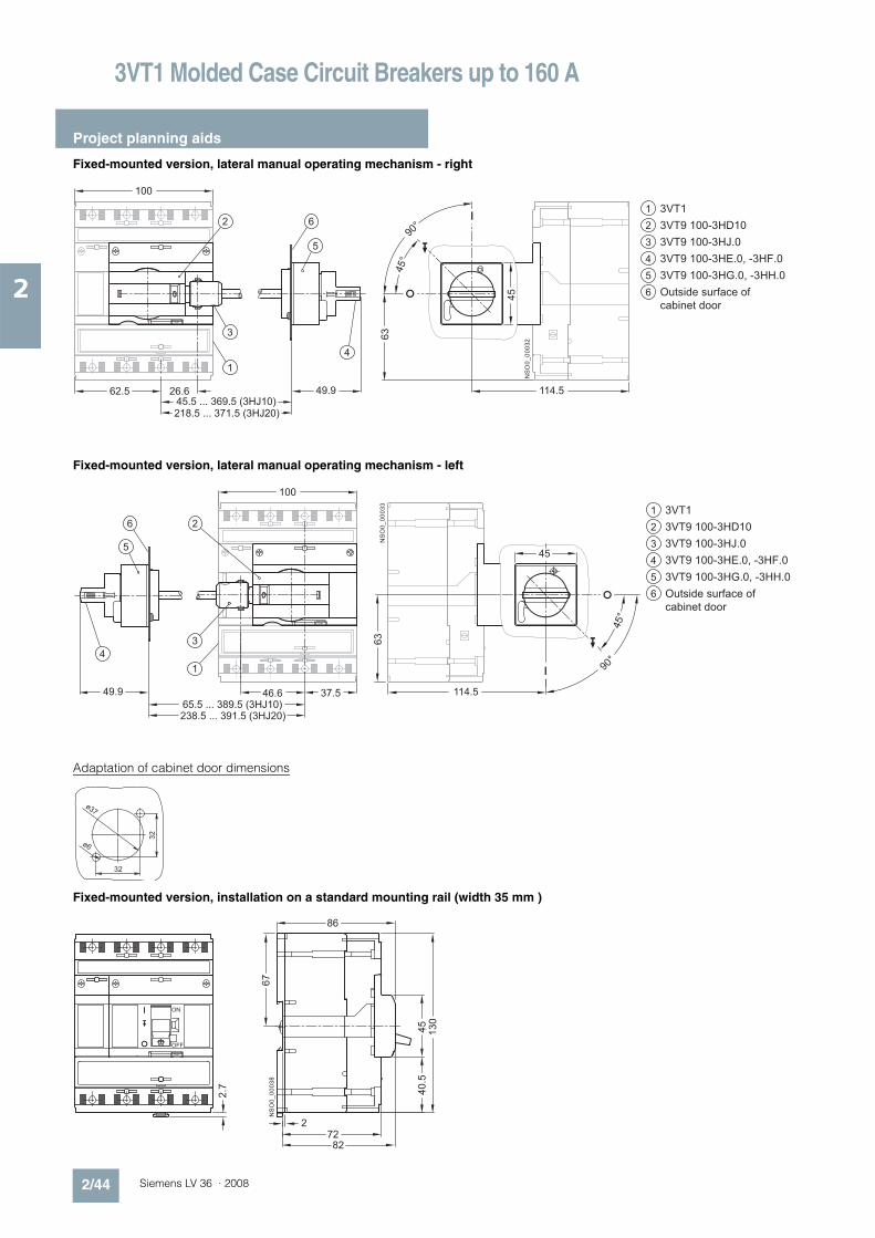
3VT1 Molded Case Circuit Breakers up to 160 A
Project planning aids
2/44 Siemens LV 36 · 2008
2
Fixed-mounted version, lateral manual operating mechanism - right
Fixed-mounted version, lateral manual operating mechanism - left
Adaptation of cabinet door dimensions
Fixed-mounted version, installation on a standard mounting rail (width 35 mm )
NS
O0
_0
00
32
TEST
100
63
90°
45°
45
1
3
2 6
5
4
62.5 49.926.645.5 ... 369.5 (3HJ10)218.5 ... 371.5 (3HJ20)
114.5
1 3VT1
2 3VT9 100-3HD10
3 3VT9 100-3HJ.0
4 3VT9 100-3HE.0, -3HF.0
5 3VT9 100-3HG.0, -3HH.0
6 Outside surface of
cabinet door
NS
O0
_0
00
33
TEST
100
63
90°
45°
45
1
4
5
6
3
2
46.649.9 37.565.5 ... 389.5 (3HJ10)238.5 ... 391.5 (3HJ20)
114.5
1 3VT1
2 3VT9 100-3HD10
3 3VT9 100-3HJ.0
4 3VT9 100-3HE.0, -3HF.0
5 3VT9 100-3HG.0, -3HH.0
6 Outside surface of
cabinet door
32
32
ø37
ø6
TEST
OFF
ON
27282
86
45
67
130
NS
O0
_0
00
38
2.7 40.5
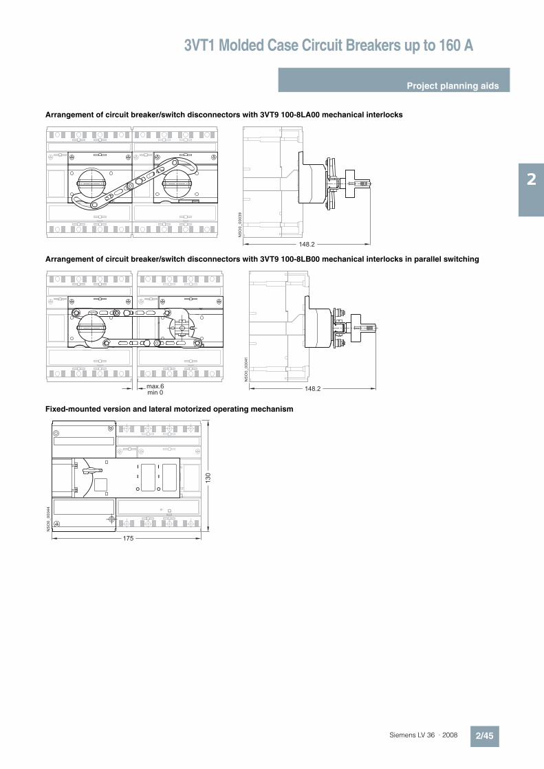
3VT1 Molded Case Circuit Breakers up to 160 A
Project planning aids
2/45Siemens LV 36 · 2008
2
Arrangement of circuit breaker/switch disconnectors with 3VT9 100-8LA00 mechanical interlocks
Arrangement of circuit breaker/switch disconnectors with 3VT9 100-8LB00 mechanical interlocks in parallel switching
Fixed-mounted version and lateral motorized operating mechanism
NS
O0
_0
00
39
TEST
148.2N
SO
0_
00
041
T TEST
148.2max.6min 0
NS
O0
_0
00
44
TEST
175
130
3VT1 Molded Case Circuit Breakers up to 160 A
Notes
2/46 Siemens LV 36 · 2008
2
7