© Siemens AG 2014 3VT1 Molded Case Circuit … LV 36 · 2014 3VT1 Molded Case Circuit Breakers up...
48
1 Siemens LV 36 · 2014 3VT1 Molded Case Circuit Breakers up to 160 A 1/2 General data 1/3 Circuit breakers · Switch disconnectors Accessories and Components 1/6 Auxiliary switches · auxiliary trip units 1/7 Manual/motorized operating mechanisms 1/9 Residual current devices 1/10 Connecting accessories 1/11 Mounting accessories 3VT1 Molded Case Circuit Breakers up to 160 A 1/12 Circuit breakers · Switch disconnectors Accessories and Components 1/16 Trip units 1/22 Auxiliary switches 1/24 Auxiliary trip units 1/25 Rotary operating mechanisms 1/28 Motorized operating mechanism 1/34 Insulating barriers and terminal covers 1/36 Residual current devices Project Planning Assistance 1/39 Dimensional drawings 3VT1 Molded Case Circuit Breakers up to 160 A Catalog Technical Information © Siemens AG 2014
-
Upload
nguyendung -
Category
Documents
-
view
213 -
download
0
Transcript of © Siemens AG 2014 3VT1 Molded Case Circuit … LV 36 · 2014 3VT1 Molded Case Circuit Breakers up...

1
Siemens LV 36 · 2014
3VT1 Molded Case Circuit Breakers up to 160 A
1/2 General data1/3 Circuit breakers · Switch disconnectors
Accessories and Components1/6 Auxiliary switches · auxiliary trip units1/7 Manual/motorized operating mechanisms1/9 Residual current devices1/10 Connecting accessories1/11 Mounting accessories
3VT1 Molded Case Circuit Breakers up to 160 A
1/12 Circuit breakers · Switch disconnectorsAccessories and Components
1/16 Trip units 1/22 Auxiliary switches1/24 Auxiliary trip units1/25 Rotary operating mechanisms1/28 Motorized operating mechanism1/34 Insulating barriers and terminal covers1/36 Residual current devices
Project Planning Assistance1/39 Dimensional drawings
3VT1 Molded Case Circuit Breakers up to 160 A
Catalog
Technical Information
LV36_2014.book Seite 1 Freitag, 31. Januar 2014 4:36 16
© Siemens AG 2014

3VT1 Molded Case Circuit Breakers up to 160 ACatalog
General data
1/2 Siemens LV 36 · 2014
1 ■ Overview
Versions and accessories
NS
O0_
0025
8b
2
34
56
8
11
1228
1
7
9 10
26
27
25
1431
30
29
13
15
16
17
21
22
1819
20
23
24
3VT circuit breakerCircular conductor terminalFront connectionRear connectionAuxiliary conductor terminalFront connecting bus with increased pole spacingInsulating barriersLaterally mounted motorized operating mechanismShunt trip unitUndervoltage trip unit
Adapter to install on 35 mm DIN railLockingtype leverSignal switchAuxiliary switchMechanical parallel switchingMechanical interlockingFront manual operating mechanismFront manual operating mechanismLateral manual operating mechanism (right)Lateral manual operating mechanism (left)Non lockable knob
Coupling driverTelescopic extension shaftLockable knobLockable knobCoupling driverExtension shaftExtension CableResidual current device (RCD)moduleConnection set for RCD, shortConnection set for RCD, long
Rotary operating mechanism
Connecting sets
Circuit breaker
123456
78
910
1112131415161718192021
2223242526272829
3031
LV36_2014.book Seite 2 Freitag, 31. Januar 2014 4:36 16
© Siemens AG 2014

3VT1 Molded Case Circuit Breakers up to 160 ACatalog
Circuit breakers · Switch disconnectors
1/3Siemens LV 36 · 2014* You can order this quantity or a multiple thereof.
1■ Overview
Circuit breaker
Circuit breaker, 3-/4-pole versions
The 3- or 4-pole versions of the circuit breakers include:• 2 connecting sets (box terminals), for connecting Cu/Al
cables1) with cross-sections of 2.5 ... 95 mm2 (these terminals are connected to the circuit breaker)
• insulating barriers• set of two mounting bolts (M3 x 30)
Switch disconnector
Switch disconnector, 3-/4-pole versions
The 3- or 4-pole versions of the switch disconnectors include:• 2 connecting sets (box terminals), for connecting Cu/Al
cables1) with cross-sections of 2.5 ... 95 mm2 (these terminals are connected to the switch disconnector)
• insulating barriers • set of two mounting bolts (M3 x 30)
■ Selection and ordering data
Rated current In Current setting of the inverse-time delayed overcurrent releases "L" IR
Operating current of the instantaneous short cir-cuit releases "I" Ii
DT Article No. PS*/ P. unit
Weight per PUapprox.
A A A kg
Circuit breakers with tripping characteristic L2)
TM3), LI function, 3-pole• with permanently fixed thermal overload trip unit,
fixed short-circuit trip unit
40 40 160 3VT1704-2DA36-0AA0 1 unit 1.04350 50 200 3VT1705-2DA36-0AA0 1 unit 1.04363 63 252 3VT1706-2DA36-0AA0 1 unit 1.06280 80 320 3VT1708-2DA36-0AA0 1 unit 1.050
100 100 400 3VT1710-2DA36-0AA0 1 unit 1.047125 125 500 3VT1712-2DA36-0AA0 1 unit 1.047160 160 640 3VT1716-2DA36-0AA0 1 unit 1.047
TM, LI function, 3-pole + N, for unprotected N-conductor• with permanently fixed thermal overload trip unit,
fixed short-circuit trip unit
40 40 160 3VT1704-2EA46-0AA0 1 unit 1.33650 50 200 3VT1705-2EA46-0AA0 1 unit 1.33663 63 252 3VT1706-2EA46-0AA0 1 unit 1.33680 80 320 3VT1708-2EA46-0AA0 1 unit 1.336
100 100 400 3VT1710-2EA46-0AA0 1 unit 1.336125 125 500 3VT1712-2EA46-0AA0 1 unit 1.336160 160 640 3VT1716-2EA46-0AA0 1 unit 1.336
TM, LIN function, 4-pole, for protected N-conductor, Per-missible load of N pole is 100%• with permanently fixed overload trip unit,
fixed short-circuit trip unit
40 40 160 3VT1704-2EH46-0AA0 1 unit 1.33650 50 200 3VT1705-2EH46-0AA0 1 unit 1.33663 63 252 3VT1706-2EH46-0AA0 1 unit 1.33680 80 320 3VT1708-2EH46-0AA0 1 unit 1.336
100 100 400 3VT1710-2EH46-0AA0 1 unit 1.336125 125 500 3VT1712-2EH46-0AA0 1 unit 1.336160 160 640 3VT1716-2EH46-0AA0 1 unit 1.336
1) For other connection methods, use connecting sets, see page 1/102) See pages 1/16 (3-pole) and 1/21 (4-pole)3) TM = Thermal-magnetic trip unit.
LV36_2014.book Seite 3 Freitag, 31. Januar 2014 4:36 16
© Siemens AG 2014

3VT1 Molded Case Circuit Breakers up to 160 ACatalog
Circuit breakers · Switch disconnectors
1/4 Siemens LV 36 · 2014* You can order this quantity or a multiple thereof.
1
Circuit breakers with tripping characteristic D1)
TM, LI function 3-pole• with adjustable thermal overload trip unit,
adjustable short-circuit trip unit
16 12.5 ... 16 160 ... 240 3VT1701-2DC36-0AA0 1 unit 1.04820 16 ... 20 200 ... 300 3VT1702-2DC36-0AA0 1 unit 1.04825 20 ... 25 250 ... 375 3VT1792-2DC36-0AA0 1 unit 1.04332 25 ... 32 160 ... 320 3VT1703-2DC36-0AA0 1 unit 1.047
40 32 ... 40 200 ... 400 3VT1704-2DC36-0AA0 1 unit 1.03850 40 ... 50 250 ... 500 3VT1705-2DC36-0AA0 1 unit 1.04363 50 ... 63 315 ... 630 3VT1706-2DC36-0AA0 1 unit 1.06280 63 ... 80 400 ... 800 3VT1708-2DC36-0AA0 1 unit 1.062
100 80 ... 100 500 ... 1000 3VT1710-2DC36-0AA0 1 unit 1.047125 100 ... 125 625 ... 1250 3VT1712-2DC36-0AA0 1 unit 1.047160 125 ... 160 800 ... 1600 3VT1716-2DC36-0AA0 1 unit 1.070
TM, LI function 3-pole +N, for unprotected N-conductor• with adjustable thermal overload trip unit,
adjustable short-circuit trip unit
16 12.5 ... 16 160 ... 240 3VT1701-2EC46-0AA0 1 unit 1.33620 16 ... 20 200 ... 300 3VT1702-2EC46-0AA0 1 unit 1.33625 20 ... 25 250 ... 375 3VT1792-2EC46-0AA0 1 unit 1.33632 25 ... 32 160 ... 320 3VT1703-2EC46-0AA0 1 unit 1.336
40 32 ... 40 200 ... 400 3VT1704-2EC46-0AA0 1 unit 1.33650 40 ... 50 250 ... 500 3VT1705-2EC46-0AA0 1 unit 1.33663 50 ... 63 315 ... 630 3VT1706-2EC46-0AA0 1 unit 1.33680 63 ... 80 400 ... 800 3VT1708-2EC46-0AA0 1 unit 1.336
100 80 ... 100 500 ... 1000 3VT1710-2EC46-0AA0 1 unit 1.336125 100 ... 125 625 ... 1250 3VT1712-2EC46-0AA0 1 unit 1.336160 125 ... 160 800 ... 1600 3VT1716-2EC46-0AA0 1 unit 1.336
TM, LIN function, 4-pole, for protected N-conductor, Per-missible load of N pole is 100%• with adjustable thermal overload trip unit,
adjustable short-circuit trip unit
16 12.5 ... 16 160 ... 240 3VT1701-2EJ46-0AA0 1 unit 1.33620 16 ... 20 200 ... 300 3VT1702-2EJ46-0AA0 1 unit 1.33625 20 ... 25 250 ... 375 3VT1792-2EJ46-0AA0 1 unit 1.33632 25 ... 32 160 ... 320 3VT1703-2EJ46-0AA0 1 unit 1.336
40 32 ... 40 200 ... 400 3VT1704-2EJ46-0AA0 1 unit 1.33650 40 ... 50 250 ... 500 3VT1705-2EJ46-0AA0 1 unit 1.33663 50 ... 63 315 ... 630 3VT1706-2EJ46-0AA0 1 unit 1.33680 63 ... 80 400 ... 800 3VT1708-2EJ46-0AA0 1 unit 1.336
100 80 ... 100 500 ... 1000 3VT1710-2EJ46-0AA0 1 unit 1.336125 100 ... 125 625 ... 1250 3VT1712-2EJ46-0AA0 1 unit 1.336160 125 ... 160 800 ... 1600 3VT1716-2EJ46-0AA0 1 unit 1.336
1) See pages 1/16 (3-pole) and 1/21 (4-pole)
Rated current In Current setting of the inverse-time delayed overcurrent releases "L" IR
Operating current of the instantaneous short cir-cuit releases "I" Ii
DT Article No. PS*/ P. unit
Weight per PUapprox.
A A A kg
LV36_2014.book Seite 4 Freitag, 31. Januar 2014 4:36 16
© Siemens AG 2014

3VT1 Molded Case Circuit Breakers up to 160 ACatalog
Circuit breakers · Switch disconnectors
1/5Siemens LV 36 · 2014* You can order this quantity or a multiple thereof.
1Rated current In Current setting of the
inverse-time delayed overcurrent releases "L" IR
Operating current of the instantaneous short circuit releases "I" Ii
DT Article No. PS*/ P. unit
Weight per PU approx.
A A A kgCircuit breakers, for short-circuit protection only (tripping characteristic N1)),for starter combination
TM, I function, 3-pole• without overload trip unit, with adjustable short-circuit trip unit
32 32 160 ... 320 3VT1703-2DB36-0AA0 1 unit 1.04340 40 200 ... 400 3VT1704-2DB36-0AA0 1 unit 1.04350 50 250 ... 500 3VT1705-2DB36-0AA0 1 unit 1.04863 63 315 ... 630 3VT1706-2DB36-0AA0 1 unit 1.048
80 80 400 ... 800 3VT1708-2DB36-0AA0 1 unit 1.048100 100 500 ... 1000 3VT1710-2DB36-0AA0 1 unit 1.050125 125 625 ... 1250 3VT1712-2DB36-0AA0 1 unit 1.059160 160 800 ... 1600 3VT1716-2DB36-0AA0 1 unit 1.048
TM, I function, 3-pole +N, for unprotected conductors• without overload trip unit, with adjustable short-circuit trip unit
32 32 160 ... 320 3VT1703-2EB46-0AA0 1 unit 1.33640 40 200 ... 400 3VT1704-2EB46-0AA0 1 unit 1.33650 50 250 ... 500 3VT1705-2EB46-0AA0 1 unit 1.33663 63 315 ... 630 3VT1706-2EB46-0AA0 1 unit 1.336
80 80 400 ... 800 3VT1708-2EB46-0AA0 1 unit 1.336100 100 500 ... 1000 3VT1710-2EB46-0AA0 1 unit 1.336125 125 625 ... 1250 3VT1712-2EB46-0AA0 1 unit 1.336160 160 800 ... 1600 3VT1716-2EB46-0AA0 1 unit 1.336
TM, I function, 4P, for protected N conductor, Permissible load of N pole is 100% • without overload trip unit, with adjustable short-circuit trip unit
32 32 160 ... 320 3VT1703-2EG46-0AA0 1 unit 1.33640 40 200 ... 400 3VT1704-2EG46-0AA0 1 unit 1.33650 50 250 ... 500 3VT1705-2EG46-0AA0 1 unit 1.33663 63 315 ... 630 3VT1706-2EG46-0AA0 1 unit 1.336
80 80 400 ... 800 3VT1708-2EG46-0AA0 1 unit 1.336100 100 500 ... 1000 3VT1710-2EG46-0AA0 1 unit 1.336125 125 625 ... 1250 3VT1712-2EG46-0AA0 1 unit 1.336160 160 800 ... 1600 3VT1716-2EG46-0AA0 1 unit 1.336
Circuit breakers with tripping characteristic M2), for motor protectionTM, LI function, 3-pole• with adjustable thermal overload trip units, fixed short-circuit trip units
16 12.5 ... 16 160 3VT1701-2DM36-0AA0 1 unit 1.04820 16 ... 20 200 3VT1702-2DM36-0AA0 1 unit 1.04825 20 ... 25 250 3VT1792-2DM36-0AA0 1 unit 1.04332 25 ... 32 315 3VT1703-2DM36-0AA0 1 unit 1.043
40 32 ... 40 400 3VT1704-2DM36-0AA0 1 unit 1.04350 40 ... 50 500 3VT1705-2DM36-0AA0 1 unit 1.04363 50 ... 63 625 3VT1706-2DM36-0AA0 1 unit 1.06280 63 ... 80 800 3VT1708-2DM36-0AA0 1 unit 1.059
100 80 ... 100 1000 3VT1710-2DM36-0AA0 1 unit 1.047
Switch disconnectors Switch disconnector, without overload protection, without short circuit protection
160 3-pole 3VT1716-2DE36-0AA0 1 unit 1.015
160 4-pole 3VT1716-2EE46-0AA0 1 unit 1.336
1) See page 1/16 (3-pole) 2) See pages 1/16 and 1/20
LV36_2014.book Seite 5 Freitag, 31. Januar 2014 4:36 16
© Siemens AG 2014

3VT1 Molded Case Circuit Breakers up to 160 ACatalog - Accessories and Components
Auxiliary switches · Auxiliary trip units
1/6 Siemens LV 36 · 2014* You can order this quantity or a multiple thereof.
1 ■ Overview
Circuit breakers can be equipped with• auxiliary switches,• alarm switches,• shunt trip units,• undervoltage trip units.
Shunt trip units can trip the circuit breaker from a remote loca-tion. A control supply voltage is required.
An undervoltage trip unit trips the circuit breaker automatically when the circuit voltage drops below 70 % Ue. The undervoltage trip unit protects motors and other equipment in case of under-voltage. A control supply voltage is required.
■ Selection and ordering data
Rated control supply voltage Us DT Article No. PS*/ P. unit
Weight per PU approx.
AC 50/60 Hz or DC kg
Auxiliary switches and alarm switches Auxiliary switches for signalling the state of the main contacts
• AC/DC 60 ... 250 V 3VT9100-2AB10 1 unit 0.020
• AC/DC 5 ... 60 V 3VT9100-2AB20 1 unit 0.010
Alarm switches for signalling the tripping of the circuit breaker by an trip unit
• AC/DC 60 ... 250 V 3VT9100-2AH10 1 unit 0.020
• AC/DC 5 ... 60 V 3VT9100-2AH20 1 unit 0.010
Shunt trip units Shunt trip units can trip the circuit breaker from a remote loca-tion.
• DC 12 V 3VT9100-1SB00 1 unit 0.050
• AC/DC 24, 48 V 3VT9100-1SC00 1 unit 0,050
• AC 110, 230 V/DC 110, 220 V 3VT9100-1SD00 1 unit 0.050
• AC 230, 400 V/DC 220 V 3VT9100-1SE00 1 unit 0.050
Undervoltage trip units Undervoltage trip units trip the circuit breaker automatically when the circuit voltage drops below 70 % Ue
• AC 24, 48 V 3VT9100-1UC00 1 unit 0.050
• AC 110, 230 V 3VT9100-1UD00 1 unit 0.050
• AC 230, 400 V 3VT9100-1UE00 1 unit 0.050
• DC 24, 48 V 3VT9100-1UU00 1 unit 0.050
• DC 110, 220 V 3VT9100-1UV00 1 unit 0.050
LV36_2014.book Seite 6 Freitag, 31. Januar 2014 4:36 16
© Siemens AG 2014

3VT1 Molded Case Circuit Breakers up to 160 ACatalog - Accessories and Components
Manual/motorized operating mechanisms
1/7Siemens LV 36 · 2014* You can order this quantity or a multiple thereof.
1■ Overview
Rotary operating mechanisms
The rotary operating mechanism must be combined from the fol-lowing parts:• For rotary operation of the circuit breaker:
- 3VT9100-3HE../HF.. knob• For operation through the switchgear cabinet door:
- 3VT9100-3HE../HF.. knob- 3VT9100-3HG../HH.. coupling driver- 3VT9100-3HJ.. extension shaft,
• For operating through side panel of switchgear cabinet (lateral operation):- 3VT9100-3HE../HF.. knob- 3VT9100-3HG../HH.. coupling driver- 3VT9100-3HJ.. extension shaft
Mechanical interlocking and parallel switching • The mechanical interlocking must be combined from the fol-
lowing parts:- 2 x 3VT9100-3HA/HB.. rotary operating mechanisms
(cannot be used with lateral operation)- 2 x 3VT9100-3HE/HF.. knobs (standard) or
1 x 3VT9100-3HE/HF.. knob (parallel switching)
■ Selection and ordering data
Version Color DT Article No. PS*/ P. unit
Weight per PU approx.
kg
Rotary operating mechanismsRotary operating mechanism
• not lockable gray 3VT9100-3HA10 1 unit 0.079
• lockable with padlock gray 3VT9100-3HA20 1 unit 0.122
• lockable with padlock yellow 3VT9100-3HB20 1 unit 0.079
• for lateral operation, mounted on the left side, not lockable
gray 3VT9100-3HC10 1 unit 0.137
• for lateral operation, mounted on the right side, not lockable
gray 3VT9100-3HD10 1 unit 0.137
Knob
• not lockable black 3VT9100-3HE10 1 unit 0.019
• lockable with padlock black 3VT9100-3HE20 1 unit 0.021
• lockable with padlock red 3VT9100-3HF20 1 unit 0.019
Coupling driver for door-coupling operating mechanism(with defeat mechanism)
Additionally requires 3VT9100-3HE10 or 3VT9100-3HE20 black knob
• degree of protection IP40 black 3VT9100-3HG10 1 unit 0.042
• degree of protection IP66 black 3VT9100-3HG20 1 unit 0.098
Additionally requires 3VT9100-3HF20 red knob
• degree of protection IP40 yellow 3VT9100-3HH10 1 unit 0.042
• degree of protection IP66 yellow 3VT9100-3HH20 1 unit 0.098
Extension shaft
• length 350 mm, can be shortened 3VT9100-3HJ10 1 unit 0.113
• length 199 ... 352 mm, telescopic 3VT9100-3HJ20 1 unit 0.092
LV36_2014.book Seite 7 Freitag, 31. Januar 2014 4:36 16
© Siemens AG 2014

3VT1 Molded Case Circuit Breakers up to 160 ACatalog - Accessories and Components
Manual/motorized operating mechanisms
1/8 Siemens LV 36 · 2014* You can order this quantity or a multiple thereof.
1
Mechanical interlocking The mechanical interlocks additionally require the following parts:
• 2 x 3VT9 100-3HA../HB.. rotary operating mechanisms• 1 or 2 x 3VT9 100-3HE/HF.. knobs
Mechanical interlocking 3VT9100-8LA00 1 unit 0.089
Mechanical interlocking for parallel switching 3VT9100-8LB00 1 unit 0.109
Version Color DT Article No. PS*/ P. unit
Weight per PU approx.
kg
Rated control supply voltage Us DT Article No. PS*/ P. unit
Weight per PU approx.
AC 50/60 Hz or DC kg
Motorized operating mechanism Laterally mounted motorized operating mechanism
For a detailed description see page 1/28.
• AC/DC 24 V 3VT9100-3MA00 1 unit 0.900
• AC/DC 48 V 3VT9100-3MB00 1 unit 0.900
• AC/DC 110 V 3VT9100-3MD00 1 unit 0.900
• AC 230 V/DC 220 V 3VT9100-3ME00 1 unit 0.900
LV36_2014.book Seite 8 Freitag, 31. Januar 2014 4:36 16
© Siemens AG 2014
3VT1 Molded Case Circuit Breakers up to 160 ACatalog - Accessories and Components
Residual current devices
1/9Siemens LV 36 · 2014* You can order this quantity or a multiple thereof.
1■ Selection and ordering data
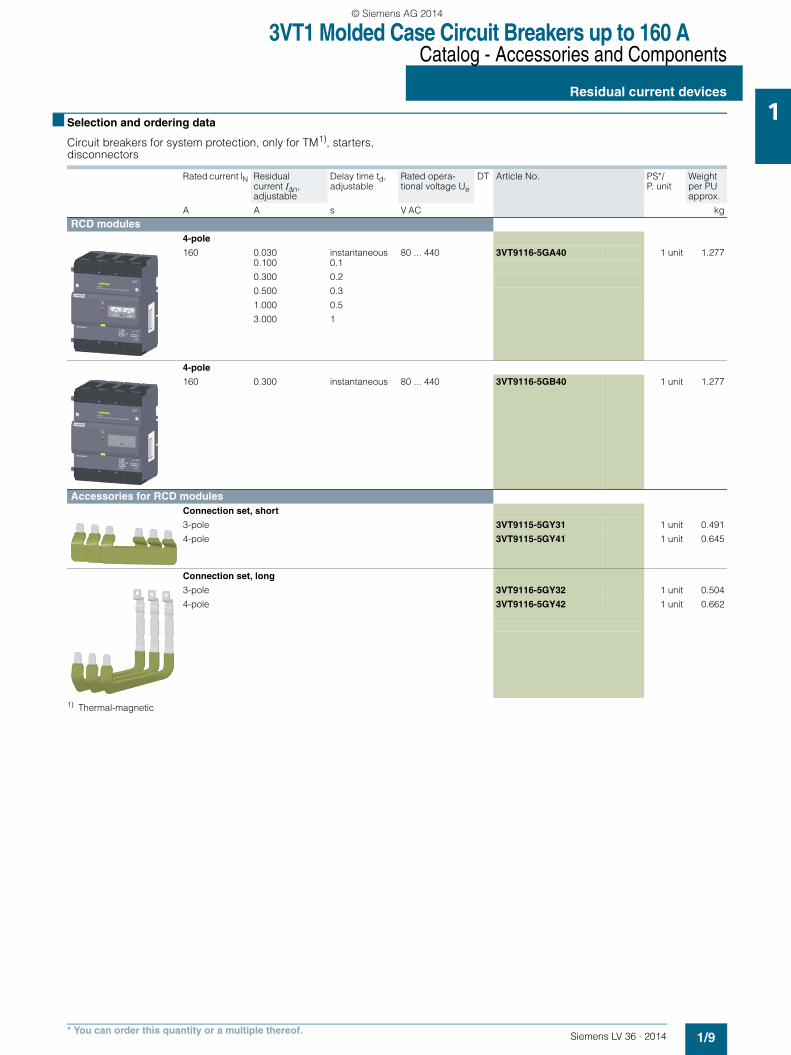
Circuit breakers for system protection, only for TM1), starters, disconnectors
1) Thermal-magnetic
Rated current IN Residualcurrent IΔn, adjustable
Delay time td, adjustable
Rated opera-tional voltage Ue
DT Article No. PS*/ P. unit
Weight per PU approx.
A A s V AC kg
RCD modules4-pole
160 0.030 instantaneous 80 ... 440 3VT9116-5GA40 1 unit 1.2770.100 0.1
0.300 0.2
0.500 0.3
1.000 0.5
3.000 1
4-pole
160 0.300 instantaneous 80 ... 440 3VT9116-5GB40 1 unit 1.277
Accessories for RCD modulesConnection set, short
3-pole 3VT9115-5GY31 1 unit 0.491
4-pole 3VT9115-5GY41 1 unit 0.645
Connection set, long
3-pole 3VT9116-5GY32 1 unit 0.504
4-pole 3VT9116-5GY42 1 unit 0.662
LV36_2014.book Seite 9 Freitag, 31. Januar 2014 4:36 16
© Siemens AG 2014

3VT1 Molded Case Circuit Breakers up to 160 ACatalog - Accessories and Components
Connecting accessories
1/10 Siemens LV 36 · 2014* You can order this quantity or a multiple thereof.
1 ■ Selection and ordering data
Version Conductor cross-sections S
Type of connection
DT Article No. PS*/ P. unit
Weight per PU approx.
mm2 kg
Terminals for fixed-mounted circuit breakersConnecting set for 3-pole versionTerminals for front connection
1 set = 3 units
-- Cu/Al busbars, cable lugs
3VT9100-4TA30 1 unit 0.055
Terminals for circular conductors 2 x 25 ... 120 Cu/Al cable 3VT9100-4TF30 1 unit 0,240
1 set = 3 units
Set includes a terminal cover, degree of protection IP20
Terminals for rear connection
1 set = 3 units
Rotation in 45-degree increments
Cu/Al busbars, cable lugs
3VT9100-4RC30 1 unit 0.179
Auxiliary conductor terminals 1.5 ... 2.5; 4 ... 6
Cu flexible conductors
3VT9100-4TN30 1 unit 0.010
Front connection bars
Increases pole spacing
1 set = 3 units
Cu/Al busbars, cable lugs
3VT9100-4ED30 1 unit 0.108
Terminals for 4-pole versionTerminal for front connection
1 set = 1 unit
For 4th pole (to be used with 3VT9100-4TA30 connecting set)
-- Cu/Al busbars, cable lugs
3VT9100-4TA00 1 unit 0.015
Terminals for circular conductors 2 x 25 ... 120 Cu/Al cable 3VT9100-4TF40 1 unit 0,250
1 set = 4units
Set includes a terminal cover, degree of protection IP20
Terminal for rear connection
1 set = 1 unit
For 4th pole (to be used with 3VT9100-4RC30 connecting set)
Cu/Al-busbars, cable lugs
3VT9100-4RC00 1 unit 0.080
Auxiliary conductor terminals
For 4th pole (to be used with 3VT9100-4TN30 connecting set)
1.5 ... 2.5; 4 ... 6
Cu flexible conductor
3VT9100-4TN00 1 unit 0.005
LV36_2014.book Seite 10 Freitag, 31. Januar 2014 4:36 16
© Siemens AG 2014

3VT1 Molded Case Circuit Breakers up to 160 ACatalog - Accessories and Components
Mounting accessories
1/11Siemens LV 36 · 2014* You can order this quantity or a multiple thereof.
1■ Selection and ordering data
Description DT Article No. PS*/ P. unit
Weight per PU approx.
kg
Accessories 3-pole versionInsulating barriers for circuit breakers
Included in the scope of supply of the circuit breaker or switch disconnector
In case of feed-in from below (power supply connected to terminals 2, 4 , 6), it is necessary to install these barriers on the bottom side
For more information, see page 1/34.
3VT9100-8CE30 1 unit 0.053
Terminal protection cover, degree of protection IP20
Increases degree of protection of the connection point to degree of protection IP20, e.g. when used with cable lugs.
3-pole 3VT9100-8CA30 1 unit 0.091
4-pole 3VT9100-8CA40 1 unit 0.080
Locking devices for toggle levers
• Enables locking of circuit breaker or switch disconnector in "switched off manually" position
• Locking is possible using a padlock with a shank diameter of up to 4 mm.
3VT9100-3HL00 1 unit 0.015
4-pole versionInsulating barrier for circuit breakers
• Included in the scope of supply of circuit breaker or switch disconnector• In case of feed-in from below, (power supply connected to terminals 2, 4, 6,
N), it is necessary to install these barriers on the bottom side
For more information, see page 1/35.
3VT9100-8CE00 1 unit 0.020
Terminal cover, degree of protection IP20
Increases the degree of protection of the connecting point to degree of protection IP20, e.g. when used with cable lugs
3VT9100-8CA40 1 unit 0.080
3-pole/4-pole versionFor mounting on a 35 mm standard DIN mounting rail and RCD
For dimensions, see page 1/46.
3VT9100-4PP30 1 unit 0.065
Extension cable for motorized operating mechanism 3VT9100-3MF00 1 unit 0.056
LV36_2014.book Seite 11 Freitag, 31. Januar 2014 4:36 16
© Siemens AG 2014
3VT1 Molded Case Circuit Breakers up to 160 ATechnical Information
Circuit breakers · Switch disconnectors
1/12 Siemens LV 36 · 2014
1 ■ Design
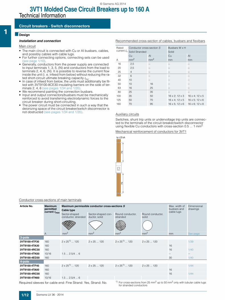
Installation and connection
Main circuit• The main circuit is connected with Cu or AI busbars, cables,
and possibly cables with cable lugs.• For further connecting options, connecting sets can be used
(see page 1/10).• Generally, conductors from the power supply are connected
to input terminals 1, 3, 5, (N) and conductors from the load to terminals 2, 4, 6, (N). It is possible to reverse the current flow inside the unit (i. e. infeed from below) without reducing the ra-ted short-circuit ultimate breaking capacity Icu.
• In case of infeed from below, the units must additionally be fit-ted with 3VT9100-8CE30 insulating barriers on the side of ter-minals 2, 4, 6 (see pages 1/34 and 1/35).
• We recommend painting the connection busbars.• Input and output connectors/busbars must be mechanically
reinforced to avoid transferring electrodynamic forces to the circuit breaker during short-circuiting.
• The power circuit must be connected in such a way that the deionizing space of the circuit breaker/switch disconnector is not obstructed (see pages 1/34 and 1/35).
Recommended cross-section of cables, busbars and flexibars
Auxiliary circuits
Switches, shunt trip units or undervoltage trip units are connec-ted to the terminals of the circuit breaker/switch disconnector using flexible Cu conductors with cross-section 0.5 ... 1 mm2.
Mechanical reinforcement of conductors for 3VT1
Conductor cross-sections of main terminals
Required sleeves for cable end: Fine Strand: Yes, Strand: No. 1) For cross-sections from 25 mm2 up to 50 mm2 only with tubular cable lugs for stranded conductors
Rated current In
Conductor cross-section S
Solid Stranded
Busbars W x H
Solid
Cu AI Cu AI
A mm2 mm2 mm mm
16 2,5 -- -- --
20 2,5 -- -- --
25 4 -- -- --
32 6 -- -- --
40 10 -- -- --
50 10 16 -- --
63 16 25 -- --
80 25 35 -- --
100 35 50 16 x 2; 12 x 3 16 x 4; 12 x 5
125 50 70 16 x 4; 12 x 5 16 x 5; 12 x 6
160 70 95 16 x 5; 12 x 6 16 x 6; 12 x 8
70
70
Ik ≤ 25 kA
Article No. Maximum permitted current Imax
Maximum permissible conductor cross-sections S Max. width of busbars and cable lugs
Dimensional drawingsCable type
Sector-shaped conductor, stranded
Sector-shaped con-ductor, solid
Round conductor, stranded
Round conductor, solid
A mm2 mm2 mm2 mm2 mm See page
3-pole3VT9100-4TF30 160 2 x 251) ... 120 2 x 25 ... 120 2 x 251) ... 120 2 x 25 ... 120 1/39
3VT9100-4TA30 160 16
3VT9100-4RC30 160 16 1/40
3VT9100-4TN30 10/16 1.5 ... 2.5/4 ... 6 -- --
3VT9100-4ED30 160 30 1/40
4-pole3VT9100-4TF40 160 2 x 251) ... 120 2 x 25 ... 120 2 x 251) ... 120 2 x 25 ... 120 1/44
3VT9100-4TA00 160 16
3VT9100-4RC00 160 16 1/44
3VT9100-4TN00 10/16 1.5 ... 2.5/4 ... 6
LV36_2014.book Seite 12 Freitag, 31. Januar 2014 4:36 16
© Siemens AG 2014

3VT1 Molded Case Circuit Breakers up to 160 ATechnical Information
Circuit breakers · Switch disconnectors
1/13Siemens LV 36 · 2014
1■ Technical specifications
✓ available, -- unavailable, + in preparation1) When reversing the circuit breaker connection (power supply connected to
terminals 2, 4, 6, (N) output to terminals 1, 3, 5, (N)), Icu does not change.2) Ranges of rated currents vary according to characteristics, see page 1/17.3) Permissible load of N pole is 100%.
4) For In <160A, see table page 1/14.
Article No. 3VT17..-2..36-0AA0 3VT1716-2DE36-0AA0 3VT17..-2..46-0AA0 3VT1716-2EE46-0AA0
Description Circuit breakers Switch disconnectors Circuit breakers 3) Switch disconnectorsNumber of poles 3 4
Standards EN 60 947-2, IEC 947-2 EN 60 947-3,IEC 947-3 EN 60 947-2, IEC 947-2 EN 60 947-3,IEC 947-3
Approval marks
Rated current In A 16 ... 1602) -- 16 ... 1602) --
Rated uninterrupted current Iu A 16 ... 1602) 160 16 ... 1602) 160
Rated operational current Ie A -- 160 -- 160
Rated operational voltage Ue V max. AC 690, max. DC 250 max. AC 690, max. DC 440
Rated frequency fn Hz 50/60
Rated impulse withstand voltage Uimp kV 8
Rated insulation voltage Ui V 690
Utilization category • selectivity AC 690 V A -- A --• switching mode AC-3 (16 ... 100 A)
AC-2 (100 ... 160 A)DC-22 A
AC-23 ADC-22 A
AC-3 (16 ... 100 A)AC-2 (100 ... 160 A)DC-22 A
AC-23 ADC-22 A
Rated short-time withstand current Icw /t -- 2 kA/ 1 s -- 2 kA/1 s
Rated ultimate short-circuit breaking capacity (rms value)1) Icu/Ue
25 kA/DC 250 V(τ = max. 15 ms)6 kA/AC 690 V12 kA/AC 500 V25 kA/AC 415 V40 kA/AC 230 V
-- 20 kA/DC 440V (τ = max. 15 ms)6 kA/AC 690 V12 kA/AC 500 V25 kA/AC 415 V40 kA/AC 230 V
--
Off-time at Icu ms 7 -- 7 --
Rated service short-circuit breaking capacity (rms value) Ics/Ue
13 kA/DC 250 V(τ = max. 10 ms)3 kA/AC 690 V6 kA/AC 500 V13 kA/AC 415 V20 kA/AC 230 V
-- 13 kA/DC 440V (τ = max. 10 ms)3 kA/AC 690 V6 kA/AC 500 V13 kA/AC 415 V20 kA/AC 230 V
--
Rated short-circuit making capacity (peak value) Icm/Ue
52 kA/AC 415 V 2,83 kA/AC 415 V 52 kA/AC 415 V 2,83 kA/AC 415 V
Losses per pole at In = 160 A4) W 15
Mechanical endurance cycles 20 000
Electrical endurance (Ue = AC 415 V ) cycles 6 000
Frequency of switching cycles/hr 120
Operating force N 55 65
Front side device protection IP40
Terminal protection IP20
Operating conditionsReference ambient temperature °C 40
Ambient temperature range °C -40 ... +55
Working environment dry and tropical climate
Degree of pollution 3
Max. elevation m 2000
Seismic resistance m/s2 3 g at 8 ... 50 Hz
Design modificationsFront/rear connection ✓/✓
Plug-in version --
Withdrawable version --
AccessoriesSwitches - auxiliary/relative/signal/leading ✓/–/✓/–
Shunt trip unit/with alarm switch ✓/✓
Undervoltage trip unit/with leading switch/with alarm switch
✓/–/✓
Front hand drive/lateral drive right/left ✓/✓/✓
Mechanical interlocking to the manual drive by Bowden wire
--/-- --/--
Motor. oper. mechanism/with oper. counter ✓/-- ✓/--
Locking-type lever ✓
LV36_2014.book Seite 13 Freitag, 31. Januar 2014 4:36 16
© Siemens AG 2014

3VT1 Molded Case Circuit Breakers up to 160 ATechnical Information
Circuit breakers · Switch disconnectors
1/14 Siemens LV 36 · 2014
1 ■ Schematics
Circuit breakers with accessories
3-pole version
Explanations
Power losses (per pole)
TEST pushbutton
Pressing the TEST pushbutton switches the circuit brea-ker/switch disconnector off and actuates the auxiliary switches.
Indication of circuit breaker tripping
When the circuit breaker was tripped by the overcurrent trip unit, the following symbol is displayed: " "
Inspection push button
by pressing you will simulate tripping of the circuit breaker by the overcurrent release, including actuating of the auxiliary switches and signal switch. Pressing requires a suitable instrument, such as wire with cross-section about 1 mm.
D1
10.Y
2
D2
10.Y
2
C2
10.Y
1
C1
10.Y
1
6.4
6.1
5.1
4.1
6.2
I>
VQ
TEST
INSPECTION
1.2
1.4
NS
O0_
0052
3b
1.1
1.1
1.2
1.4
1.3V
T910
0-2A
H10
2.2
2.4
3.2
3.4
3VT9
100-
1U.0
0
3VT9
100-
1S.0
0 4.4
4.2
5.4
5.2
J
6.3V
T910
0-2A
B10
5.3V
T910
0-2A
B10
4.3V
T910
0-2A
B10
3.3V
T910
0-2A
B10
2.3V
T910
0-2A
B10
or 1
.3VT
9100
-2AB
10
2.1
3.1
31 5
2 4 6
U< U
auxiliary alarm or aux. auxiliary auxiliary
Switches or Auxiliary releases Main circuit Switches
acc.comp. No. 10 acc.c. No. 6 acc.c. No. 1 acc.c. No. 2 acc.c. No. 3acc.c. No. 5 acc.c. No. 4
or
J 3VT1 circuit breaker
Q main contacts
V trip-free mechanism
TEST test push button
3VT9100-1U.00 undervoltage trip unit
3VT9100-1S.00 shunt trip unit
INSPECTION inspection push button
acc. c. accessory compartment
acc. comp. accessory compartment
Rated current In Power loss P per pole of circuit breaker at maximum current
A W
16 4
20 4
25 4
32 4
40 4
50 5
63 6
80 7
100 10
125 15
160 15
TEST pushbutton
Inspection push button
LV36_2014.book Seite 14 Freitag, 31. Januar 2014 4:36 16
© Siemens AG 2014

3VT1 Molded Case Circuit Breakers up to 160 ATechnical Information
Circuit breakers · Switch disconnectors
1/15Siemens LV 36 · 2014
14-pole version
Explanations
9.4
9.1
9.2
3VT9
100
-2A
B.0
8.4
8.1
8.2
3VT9
100
-2A
B.0
7.4
7.1
7.2
3VT9
100
-2A
B.0
J
6.4
6.1
6.2
3VT9
100
-2A
B.0
5.4
5.1
5.2
3VT9
100
-2A
B.0
4.4
4.1
4.2
3VT9
100
-2A
B.0
I>
V
TEST
INSPECTION
1.2
1.4
NS
O0_
0000
1b
1.1
1.1
1.2
1.4
3VT9
100
-2A
H.0
3VT9
100
-2A
B.0
2.2
2.4
3VT9
100
-2A
B.0
3.2
3.4
3VT9
100
-2A
B.0
2.1
3.1
D1
U<
3VT9
100
-1U
.00 C1
U
3VT9
100
-1S
.00
N
T
10.Y
2
10.Y
2
10.Y
1
10.Y
1
D2
C2
2 4 6
N
Q
1 3 5
J
Switches
auxiliary auxiliary auxiliary
auxiliary auxiliary auxiliary alarm or aux. auxiliary auxiliary
Switches or Auxiliary starters Main circuit Switches
acc.c. No. 9 acc.c. No. 8 acc.c. No. 7
acc.c. No. 6 acc.c. No. 5 acc.c. No. 4 acc.c. No. 1 acc.c. 2 acc.c. 3acc.comp. No. 10
or
or
J 3VT1 circuit breakers
Q main contacts
T thermomagnetic trip unit3-pole +N (3 poles protected, N-pole unprotected)4-pole (all four poles protected)
V trip-free mechanism
TEST test pushbutton
3VT9100-1U.00 undervoltage trip unit
3VT9100-1S.00 shunt trip unit
INSPECTION inspection push button
acc. c. accessory compartment
acc. comp. accessory compartment
LV36_2014.book Seite 15 Freitag, 31. Januar 2014 4:36 16
© Siemens AG 2014

3VT1 Molded Case Circuit Breakers up to 160 ATechnical Information - Accessories and Components
Trip units
1/16 Siemens LV 36 · 2014
1 ■ Overview
Trip units, 3-pole version
Trip units are integrated in the circuit breakers.
Tripping characteristics
Circuit breakers are available with four types of tripping charac-teristics. They are designated with the letters:
"L" - lines For protection of lines with low starting currents3VT1 circuit breakers with characteristic "L" have a pre-set and fixed rated current value. The circuit breakers feature In values in a standardized current range from 40 A to 160 A (see "Ranges of trip units and their possible settings"). Short-circuit trip units are fixed at 4 x In.
"D" - distribution For protection of lines and transformers3VT1 circuit breakers with characteristic "D" have the option of setting to a reduced current in a range of approximately 0.75 ... 1 In. The circuit breakers feature In values in a standardized cur-rent range from 16 A to 160 A (see "Ranges of trip units and their possible settings"). The short-circuit trip unit is adjustable. Setting values are shown in the table on page 1/17.
"M" - motorFor motor protection3VT1 circuit breakers with characteristic "M" have the option of setting a reduced current in a range of approximately 0.75 ... 1 In. The circuit breakers feature In values in a standar-dized series of currents from 16 A to 100 A (see "Ranges of trip units and their possible setting"). The short-circuit trip unit is fixed at the value of 10 x In.See page 1/20.
"N" - short-circuit trip unit only3VT1 circuit breakers with characteristic "N" have a short circuit trip unit only. They feature In values in a standardized series of currents ranging from 32 A to 160 A. The short-circuit trip unit is adjustable. The values are shown in the table on page 1/17.
Article Numbers
The article number of a circuit breaker depends on the rated cur-rent and on the tripping characteristics. For example: Motor protection with In = 32 A.The article number is: 3VT1703-3DM36-0AA0.
Setting of tripping characteristics
• Time-dependent trip unit (thermal) L (for circuit breakers with characteristics "D" and "M"). The time-dependent trip unit for overload protection Ir (instantaneous) is adjusted in a con-tinuous range using the Ir adjustment dial on the overload trip unit. The Ir adjustment range is 0.75 ... 1 In.
• Time-independent trip unit (short-circuit trip unit) I (for circuit breakers with characteristics "D" and "N"). With an time-independent instantaneous trip unit (value of the short circuit current Ii), adjustment is possible within a continuous range. All values are shown in the table on page 1/17.
Circuit breakers with characteristic
"L":
"M":
"D":
"N":
NS
O0_
0050
2
t
I
L I
NS
O0_
0004
8
t
I
L I
IrN
SO
0_00
500
t
I
L I
Ir
Ii
NS
O0_
0021
6
t
I
L I
Ii
LV36_2014.book Seite 16 Freitag, 31. Januar 2014 4:36 16
© Siemens AG 2014

3VT1 Molded Case Circuit Breakers up to 160 ATechnical Information - Accessories and Components
Trip units
1/17Siemens LV 36 · 2014
1Derating in accordance with ambient temperature
Current ranges of trip units and their possible settings at 40 °C
Current ranges of trip units and their possible settings at 40 °C
Rated current In
Permissible load at
A + 70 °C + 65 °C +60 °C + 55 °C + 50 °C + 40 °C +20 °C -15 ~ -40 °C
16 14 14.5 14.5 15 15.5 16 17 19
20 18 18.5 18.5 19 19.5 20 22 25
25 21 21.5 22 23 24 25 28 31
32 25 27 28 29 30.5 32 36 41
40 34 35.5 37 38 39 40 45 53
50 43 45 47 48 49 50 56 66
63 50 53 55 57 59 63 69 83
80 63 67 70 73 75 80 88 100
100 80 84 88 92 95 100 108 122
125 97 102 107 112 117 125 133 145
160 130 135 140 145 151 160 168 175
Rated current In
3VT17..-2DA36-0AA0 3VT17..-2DC36-0AA0 3VT17..-2DM36-0AA0 3VT17..-2DB36-0AA0
Overload protection Ir
Short circuit protection Ii (ins-tantaneous)
Overload protection Ir
Short circuit protection Ii (ins-tantaneous)
Overload protection Ir
Short circuit protection Ii (ins-tantaneous)
Overload protection Ir
Short circuit protection Ii (ins-tantaneous)
A A A A A A A A A
16 -- -- 12,5 ... 16 160 ... 240 12,5 ... 16 160 -- --
20 -- -- 16 ... 20 200 ... 300 16 ... 20 200 -- --
25 -- -- 20 ... 25 250 ... 375 20 ... 25 250 -- --
32 -- -- 25 ... 32 160 ... 320 25 ... 32 320 -- 160 ... 320
40 40 160 32 ... 40 200 ... 400 32 ... 40 400 -- 200 ... 400
50 50 200 40 ... 50 250 ... 500 40 ... 50 500 -- 250 ... 500
63 63 252 50 ... 63 315 ... 630 50 ... 63 630 -- 315 ... 630
80 80 320 63 ... 80 400 ... 800 63 ... 80 800 -- 400 ... 800
100 100 400 80 ... 100 500 ... 1000 80 ... 100 1000 -- 500 ... 1000
125 125 500 100 ... 125 625 ... 1250 -- -- -- 625 ... 1250
160 160 640 125 ... 160 800 ... 1600 -- -- -- 800 ... 1600
Rated current In
3VT17..-2EA46-0AA0 3VT17..-2EC46-0AA0 3VT17..-2EB46-0AA0
Overload protection Ir Short circuit protection Ii (instantaneous)
Overload protection Ir Short circuit protection Ii (instantaneous)
Overload protection Ir Short circuit protection Ii (instantaneous)
A A A A A A A
16 - -- 12,5 ... 16 160 ... 240 - -
20 - -- 16 ... 20 200 ... 300 - -
25 - -- 20 ... 25 250 ... 375 - -
32 - -- 25 ... 32 160 ... 320 - 160 ... 320
40 40 160 32 ... 40 200 ... 400 - 200 ... 400
50 50 200 40 ... 50 250 ... 500 - 250 ... 500
63 63 252 50 ... 63 315 ... 630 - 315 ... 630
80 80 320 63 ... 80 400 ... 800 - 400 ... 800
100 100 400 80 ... 100 500 ... 1000 - 500 ... 1000
125 125 500 100 ... 125 625 ... 1250 - 625 ... 1250
160 160 640 125 ... 160 800 ... 1600 - 800 ... 1600
LV36_2014.book Seite 17 Freitag, 31. Januar 2014 4:36 16
© Siemens AG 2014

3VT1 Molded Case Circuit Breakers up to 160 ATechnical Information - Accessories and Components
Trip units
1/18 Siemens LV 36 · 2014
1 Characteristic "L", In = 40, 50, 63, 80, 100, 125, 160 A
Characteristic "D", In = 16, 20, 25 A
Characteristic "D", In = 32, 40, 50, 63, 80, 100, 125, 160 A
Characteristic "M", In = 16, 20, 25 A
NSO0_00049
20
200
2000
50
500
5000
10
100
1000
10000
t [s]
1 2 5 20 5010
L
I
0.1 0.2 0.5
In = 40 … 160 A
1.05 1.30
x In
0.010.02
0.050.10.2
0.512
5
L
NSO0_00050
20
200
2000
50
500
5000
10
100
1000
10000
t [s]
1 2 5 20 50100.1 0.2 0.5x In
0.010.02
0.050.10.2
0.512
5
1.05 1.30
L
In = 16 … 25 A
I
NSO0_00051
20
200
2000
50
500
5000
105
100
1000
10000
t [s]
1 2 5 20 50100.1 0.2 0.5x In
0.010.02
0.050.10.2
0.512
1.05 1.30
In = 32 … 160 A
I
L
NSO0_00052
20
200
2000
50
500
5000
10
100
1000
10000
t [s]
1 2 5 20 50100.1 0.2 0.5x In
0.010.02
0.050.10.2
0.512
5
1.00 1.20
L
I
In = 16 … 25 A
LV36_2014.book Seite 18 Freitag, 31. Januar 2014 4:36 16
© Siemens AG 2014

3VT1 Molded Case Circuit Breakers up to 160 ATechnical Information - Accessories and Components
Trip units
1/19Siemens LV 36 · 2014
1Characteristic "M", In = 32, 40, 50, 63, 80, 100 A
Characteristic "N", In = 32, 40, 50, 63, 80, 100, 125, 160 A
NSO0_00053
20
200
2000
50
500
5000
10
100
1000
10000
t [s]
x In
0.010.02
0.050.10.2
0.512
5
1.00 1.20
1 2 5 20 50100.1 0.2 0.5
I
In = 32 … 100 A
L
20
200
2000
50
500
5000
10
100
1000
10000
t [s]
x In
0.010.02
0.050.1
0.2
0.512
5
1 2 5 20 50100.1 0.2 0.5
NSO0_00054
I
In = 32 … 160 A
LV36_2014.book Seite 19 Freitag, 31. Januar 2014 4:36 16
© Siemens AG 2014

3VT1 Molded Case Circuit Breakers up to 160 ATechnical Information - Accessories and Components
Trip units
1/20 Siemens LV 36 · 2014
1 Trip units, with tripping characteristic M class
The tripping time of the 3-pole trip unit of 3VT1 circuit breakers with characteristic M at 7.2 In corresponds to the tripping clas-ses 10A, 10 and 20 according to EN 60947-4-1.
Plate of the trip units with characteristic M
Setting IR and Ii for circuit breakers with characteristic "D"
Adjusting IR Adjusting Ii
Connection of 3-/4-pole 3VT1 circuit breakers in DC circuits
IC01
_001
64
I
LoadLoad
Connection of 4P circuit breaker in DC circuit up to 440 V DC
DC
Connection of 3P circuit breaker in DC circuit up to 250 V DC
DC
2
1
6
5
4
3
N
QQN
NS
O0_
0058
2a
+
2
1
6
5
4
3
J
+
Rated current In
Article No. Class
16 A 3VT1701-2DM36-0AA0 10A
20 A 3VT1702-2DM36-0AA0 10A
25 A 3VT1792-2DM36-0AA0 10A
32 A 3VT1703-2DM36-0AA0 10
40 A 3VT1704-2DM36-0AA0 10
50 A 3VT1705-2DM36-0AA0 20
63 A 3VT1706-2DM36-0AA0 20
80 A 3VT1708-2DM36-0AA0 20
100 A 3VT1710-2DM36-0AA0 20
Installation positions
I201
_189
60
90°
90°90°
25°
LV36_2014.book Seite 20 Freitag, 31. Januar 2014 4:36 16
© Siemens AG 2014

3VT1 Molded Case Circuit Breakers up to 160 ATechnical Information - Accessories and Components
Trip units
1/21Siemens LV 36 · 2014
1Trip units, 4-pole version
Trip units are integrated into the 3VT1 circuit breakers.
It is not possible to deinstall or exchange the trip units.4-pole circuit breakers are manufactured in the following versions:• 3-pole +N (three poles protected, N-pole unprotected)• 4-pole (all four poles protected)
The permissible load of the N-pole is 100% In.
Tripping characteristics
The circuit breakers are delivered with three types of tripping characteristics, designated by the following letters:
"L" - lines For protection of lines with low starting currents3VT1 circuit breakers with characteristic "L" have a fixed value of rated current I (without In control). The circuit breakers feature In values of standard current range 40 ... 160 A, see "Ranges of trip units and their possible setting". The short-circuit trip unit has a fixed setting to 4 x In.
"D" - distribution For protection of lines and transformers3VT1 circuit breakers with characteristic "D" can be set to a re-duced current in the range of approx. 0.75 ... 1 In. The circuit breakers feature In values within a standard current range of 16 ... 160 A. Setting values are shown in the table on page 1/17.
"N" - short-circuit For protection against short circuits only3VT1 circuit breakers with characteristic "N" have a short circuit trip unit only. They feature circuit breaker values within a stan-dard current range of 32 ... 160 A. The short circuit trip unit is ad-justable. The values are shown in the table on page 1/17.
Article Numbers
The article number of a circuit breaker depends on the rated cur-rent and on the tripping characteristics.
For example: Protection of a circuit with In = 40 A.The article number is 3VT1704-2EC46-0AA0.
Setting of tripping characteristics
• Time-dependent trip unit (thermal) L (for circuit breakers with characteristics "D" and "M"). The time-dependent trip unit for overload protection Ir (instantaneous), is adjusted in a continuous range using the Ir adjustment dial on the overload trip unit. The Ir adjustment range is 0.75 ... 1 In.
• Time-independent instantaneous trip unit (short-circuit trip unit) I (for circuit breakers with characteristics "D" and "N"). With a time-independent instantaneous trip unit (value of the short circuit current Ii), adjustment is possible within a continuous range. All values are shown in the table on page 1/17.
Circuit breakers with characteristic
"L"
"D"
"N"
NS
O0_
0050
2
t
I
L I
NS
O0_
0050
0
t
I
L I
Ir
Ii
NS
O0_
0021
6
t
I
L I
Ii
LV36_2014.book Seite 21 Freitag, 31. Januar 2014 4:36 16
© Siemens AG 2014

3VT1 Molded Case Circuit Breakers up to 160 ATechnical Information - Accessories and Components
Auxiliary switches
1/22 Siemens LV 36 · 2014
1 ■ Overview
Auxiliary switches
Auxiliary and alarm switches
Function, name and location of switches
1) In accessory compartment 1, a 3VT9100-2AB10 auxiliary switch and 3VT9100-2AH10 alarm switch cannot be used simultaneously.
2) When one of accessory compartments 4, 5 or 6 is already in use for auxili-ary switches, a shunt trip unit or undervoltage trip unit cannot be installed additionally.
Location of switches in accessory compartments
Location of accessory compartments in a 3-pole 3VT1 circuit breaker/switch disconnector.
Location of accessory compartments in a 4-pole 3VT1 circuit breaker/switch disconnector.
When using one of the accessory compartments 4, 5 or 6, neither a shunt trip unit nor an undervoltage trip unit can be ins-talled.
Article No. Type Switch location Switch function
3VT9100-2AB10 3VT9100-2AB20
Auxiliaryswitch
Accessory compartment 11), 2, 3, 4, 5, 62)
Signals the condition of the main contact of the circuit brea-ker/ switch discon-nector
3VT9100-2AH10 3VT9100-2AH20
Alarm switch
Accessory compartment 11)
Signals whether the circuit breaker was tripped by the trip unit
LV36_2014.book Seite 22 Freitag, 31. Januar 2014 4:36 16
© Siemens AG 2014

3VT1 Molded Case Circuit Breakers up to 160 ATechnical Information - Accessories and Components
Auxiliary switches
1/23Siemens LV 36 · 2014
1■ Function
Switching states (4-pole)
0 = contact open, 1 = contact closed
Switching states (3-pole)
0 = contact open, 1 = contact closed
■ Technical specifications
Accessory compartment 1 ... 9 1 10
Switching states of the circuit breaker
Leve
r p
ositi
on
Pos
ition
of t
he m
ain
cont
acts
3VT9
100-
2AB
10
3VT9
100-
2AH
10
3VT9
100-
1UC
/UD
/UE
..3V
T910
0-1S
C/S
D/S
E..
Switched on 1 1 0 0 1 1
Switched off manually 0 0 1 0 1 1
Switched off by the trip unit or INSPECTION button
0 0 1 1 0 1
Switched off by auxiliary trip unit 0 0 1 0 1 0
Switched off by TEST button 0 0 1 0 1 1
NS
O0_
0009
3
Accessory compartment 1 ... 6 1 10
Switching states of the circuit-breaker
Leve
r p
ositi
on
Pos
ition
of t
he m
ain
cont
acts
3VT9
100-
2AB
10
3VT9
100-
2AH
10
3VT9
100-
1S...
3VT9
100-
1U...
Switched on 1 1 0 0 1 1
Switched off manually 0 0 1 0 1 1
Switched off by the trip unit or INSPECTION button
0 0 1 1 0 1
Switched off by auxiliary trip unit 0 0 1 0 1 0
Switched off by TEST button 0 0 1 0 1 1
NS
O0_
0009
3
Article No. 3VT9100-2AB10, 3VT9100-2AH10
3VT9100-2AB20, 3VT9100-2AH20
Rated operational voltage Ue V AC 60 ... 250 VDC 60 ... 250 V
AC 5 ... 60 V DC 5 ... 60 V
Rated insulation voltage Ui V 250 V
Rated impulse withstand voltage Uimp kV 4 kV
Rated frequency fn Hz 50/60 Hz
Rated operational current Ie/Ue
AC-12 6 A/250 V 0.0004 ... 0.1 A/5 ... 60 V
AC-15 5 A/60 V, 3 A/110 V, 1.5 A/230 V 0.0004 ... 0.1 A/5 ... 60 V
DC-12 0.25 A/250 V 0.1 A/5 ... 60 V
DC-13 0.5 A/60 V, 0.2 A/110 V, 0.1 A/250 V 0.0004 ... 0.1 A/5 ... 60 V
Thermal current Ith A 6 A 0.5 A
Contacts arrangement 001
Connector cross-section S mm2 0.5 ... 1
Terminal protection (connected switch)
IP20
LV36_2014.book Seite 23 Freitag, 31. Januar 2014 4:36 16
© Siemens AG 2014

3VT1 Molded Case Circuit Breakers up to 160 ATechnical Information - Accessories and Components
Auxiliary trip units
1/24 Siemens LV 36 · 2014
1 ■ Design
Auxiliary trip units
Shunt trip unit Undervoltage trip unit
Location of auxiliary trip unit
One auxiliary trip unit can be installed in accessory compartment 10
The article number of the auxiliary trip unit depends on the rated operational voltage
The specific rated operational voltage of the shunt trip unit is set by jumpers located on the trip unit. The standard setting by the manufacturer is always to the value corresponding to the article number.
Schematics
Shunt trip unit Undervoltage trip unit
■ Technical specifications
Ue Article No.
AC/DC 24/48 V 3VT9100-1SC00
AC 110/230 V, DC 110/220 V 3VT9100-1SD00
AC 230/400 V, DC 220 V 3VT9100-1SE00
DC 12 V 3VT9100-1SB00
Ue Article No.
AC/DC 24/48 V 3VT9100-1UC00
AC 110/230 V, DC 110/220 V 3VT9100-1UD00
AC 230/400 V, DC 220 V 3VT9100-1UE00
C1
U
C2
10.Y
2
N-
3VT9
100-
1S.0
L+
NS
O0_
0005
5a
10.Y
1 D1
U<
D2
10.Y
2N-
3VT9
100-
1U.0
L+
NS
O0_
0005
6a
10.Y
1
Article No. 3VT9100-1S.00
Rated operational voltage Ue AC 24/48/110/230/400 V DC 12/24/48/110/220 V
Rated frequency fn 50/60 Hz
Input power at 1.1 Ue
• AC 2 VA
• DC 2 W
Characteristics U ≥ 0.7 Ue: circuit breaker must trip
Time before switching off 15 ms
Continuous load yes
Connection cross-section S 0,5 ... 1 mm2
Terminal protection (connected trip unit)
IP20
Location in accessory compartment no. 10
Alarm switch - signals that the circuit breaker was switched off by the shunt trip unit
Rated operational voltage Ue AC 230 V
Rated insulation voltage Ui 250 V
Rated impulse withstand voltage Uimp 4 kV
Rated frequency fn 50/60 Hz
Rated operational current Ie/Ue 2 A/AC 230 V
Thermal current Ith 6 A
Contact arrangement 01
Article No. 3VT9100-1U.00
Rated operational voltage Ue AC 24/48/110/230/400 V DC 24/48/110/220 V
Rated frequency fn 50/60 Hz
Input power at 1.1 Ue
• AC 2 VA
• DC 2 W
Characteristics U ≤ 0.35 Ue: circuit breaker must tripU ≥ 0.85 Ue: circuit breaker can be switched on
Time before switching off 15 ms
Continuous load yes
Connector cross-section S 0.5 ... 1 mm2
Terminal protection (connected trip unit)
IP20
Location in accessory compartment no. 10
Alarm switch - signals that the circuit breaker was switched off by the undervoltage trip unit
Rated operational voltage Ue AC 230 V
Rated insulation voltage Ui 250 V
Rated impulse withstand voltage Uimp 4 kV
Rated frequency fn 50/60 Hz
Rated operational current Ie/Ue 2 A/AC 230 V
Thermal current Ith 6 A
Contact arrangement 01
LV36_2014.book Seite 24 Freitag, 31. Januar 2014 4:36 16
© Siemens AG 2014

3VT1 Molded Case Circuit Breakers up to 160 ATechnical Information - Accessories and Components
Rotary operating mechanisms
1/25Siemens LV 36 · 2014
1■ Design
Rotary operating mechanisms
The rotary operating mechanism actuates the circuit brea-kers/switch disconnector when the operator turns the knob, e.g. in order to switch machines on and off. The modular concept of the operating mechanism allows simple mounting on the circuit breaker. Mounting can be done after having removed the acces-sory compartment cover. An attached drive can be sealed (with sealing wire). The drive and its accessories are ordered separa-tely to match the requirements (see page 1/7).• The rotary operating mechanism is mounted directly on the
circuit breaker or switch disconnector.• The coupling driver is fixed to the switchgear cabinet door and
provides for degree of protection IP40 or IP66. • The knob is mounted onto the rotary operating mechanism or
onto the coupling driver.• The extension shaft is supplied in two versions, standard
(length 350 mm - can be shortened) and telescopic (adjus-table length 199 ... 352 mm). It is fitted onto the rotary opera-ting mechanism.
The rotary operating mechanism makes it possible to actuate the circuit breaker:
Operation from the front panel of the circuit breaker (Fig. 1)3VT9100-3HA/HB.. rotary operating mechanism + 3VT9100-3HE/HF.. knob
Fig. 1: Rotary operating mechanism with knob
Operation through the switchgear cabinet door (Fig. 2)3VT9100-3HA/HB.. rotary operating mechanism + 3VT9100-3HJ.. extension shaft + 3VT9100-3HG/HH.. coupling driver + 3VT9100-3HE/HF.. knob
Fig. 2: Rotary operating mechanism with extension shaft, coupling driver and knob
Operation through the side wall of the switchgear cabinet (Fig. 3)
in left- or right-side designs of rotary operating mechanisms for lateral operation 3VT9100-3HD10 (right) or 3VT9 100-3HC10 (left) + 3VT9100-3HJ.. extension shaft + 3VT9100-3HG/HH.. coupling driver + 3VT9100-3HE/HF.. knob.
Fig. 3: Lateral rotary operating mechanism with extension shaft, coupling driver and knob
Enhanced safety for operator• The rotary operating mechanism and knob allow operators to
lock the circuit breaker into the "switched off manually" posi-tion. The rotary operating mechanism and lever can be locked with up to three padlocks with a shaft diameter up to 4 mm.
• Every coupling driver prevents the switchgear cabinet door from opening when the circuit breaker is switched on or if it was tripped. By means of the coupling driver it is possible to switch off this locking and to open the door. Locking of the switchgear cabinet door is also possible in the OFF mode of the circuit breaker. It is necessary to activate the locking by means of the knob on the coupling drive and to lock the hand drive arm.
• Two circuit breakers with rotary operating mechanism can also be provided with reciprocal mechanical interlocking or me-chanical parallel switching (see page 1/27).
LV36_2014.book Seite 25 Freitag, 31. Januar 2014 4:36 16
© Siemens AG 2014

3VT1 Molded Case Circuit Breakers up to 160 ATechnical Information - Accessories and Components
Rotary operating mechanisms
1/26 Siemens LV 36 · 2014
1 Features
Article No. Description Color Permits operator to lock the circuit brea-ker in OFF mode
Degree of Protection
Switchgear cabinet door is locked when circuit breaker is
Length mm
switched on switched off manually and locked
3VT9100-3HA10 Rotary operating mechanism gray no -- -- -- --
3VT9100-3HA20 Rotary operating mechanism gray yes -- -- -- --
3VT9100-3HB20 Rotary operating mechanism yellow yes -- -- -- --
3VT9100-3HC10 Rotary operating mechanism - lateral, left
gray no -- - -- --
3VT9100-3HD10 Rotary operating mechanism - lateral, right
gray no -- - -- --
3VT9100-3HE10 Knob black no -- -- -- --
3VT9100-3HE20 Knob, lockable with padlock black yes -- -- -- --
3VT9100-3HF20 Knob, lockable with padlock red yes -- -- -- --
3VT9100-3HG10 Coupling driver black -- IP40 yes yes --
3VT9100-3HH10 Coupling driver yellow -- IP40 yes yes --
3VT9100-3HG20 Coupling driver black -- IP66 yes yes --
3VT9100-3HH20 Coupling driver yellow -- IP66 yes yes --
3VT9100-3HJ10 Extension shaft (can be shortened) -- -- -- -- -- 350
3VT9100-3HJ20 Extension shaft, telescopic -- -- -- -- -- 199 ... 352
LV36_2014.book Seite 26 Freitag, 31. Januar 2014 4:36 16
© Siemens AG 2014

3VT1 Molded Case Circuit Breakers up to 160 ATechnical Information - Accessories and Components
Rotary operating mechanisms
1/27Siemens LV 36 · 2014
1Mechanical interlockig and mechanical interlocking for parallel switching
3VT9100-8LA00 mechanical interlocking
Mechanical interlocking make sure that two circuit breakers can-not trip simultaneously, but always just individually. Both circuit breakers may be switched off simultaneously. Interlocking can be used between two 3VT1 circuit breakers. Each circuit breaker must be furnished with a rotary operating mechanism – at least one of them with a rotary operating mechanism and a knob (see page 1/25).
When using a mechanical interlocking it is required to comply with the dimensions shown in the figure and in the table.
Arrangement of circuit breakers/switch disconnectors with 3VT9100-8LA00 mechanical interlocking
3VT9100-8LB00 mechanical interlocking for parallel switching
Mechanical interlocking for parallel switching are for simultane-ous switching of two circuit breakers. Parallel switching can be used between two 3VT1 circuit breakers. Each circuit breaker must be furnished with a rotary operating mechanism and at least one of them with a knob (see page 1/25).
When using a mechanical interlocking for parallel switching it is required to comply with the dimensions shown in the figure and in the table.
Arrangement of circuit breakers/switch disconnectors with 3VT9100-8LB00 mechanical interlocking for parallel switching
Dimensions mm
X 87.5 or 100
L 94.5 or 106
NS
O0_
0005
7
L
X
NS
O0_
0005
9
12.5 or 25
Dimensions mm
X 75 or 87.5 or 100
L to be determined
NS
O0_
0005
8
X
L
NS
O0_
0006
0
0 or 12.5 or 25
LV36_2014.book Seite 27 Freitag, 31. Januar 2014 4:36 16
© Siemens AG 2014

3VT1 Molded Case Circuit Breakers up to 160 ATechnical Information - Accessories and Components
Motorized operating mechanism
1/28 Siemens LV 36 · 2014
1 ■ Design
Motorized operating mechanism
The motorized operating mechanism is an accessory to the cir-cuit breaker/switch disconnector, by means of which it is possi-ble to switch the circuit breaker or switch disconnector remotely on and off. The modular design of the motorized operating me-chanism enables its simple attachment to the circuit breaker (also in addition to a rotary operating mechanism). The moto-rized operating mechanism is used for both remote and local control of 3VT1 3-pole and 4-pole circuit breakers. The circuit breaker with attached motorized operating mechanism can be installed on a mounting plate or on a standard DIN mounting rail. The motorized operating mechanism is fastened by means of a bayonet mechanism to the circuit breaker.
3VT1 circuit breakers with motorized operating mechanism are intended for industrial, power engineering and infrastructure ap-plications. The motorized operating mechanisms are for direct actuation of the circuit breaker, without a spring storage unit.
The motorized operating mechanism can work in local or remote control mode. The local control mode is used, for instance, in case of loss of the control voltage. Local control of the circuit breaker is only accessible after lifting the transparent safety co-ver off the operating mechanism. This procedure locks the re-mote electrical control circuits. The lifted position of the cover can be indicated remotely.
The circuit breaker is switched on and off by means of the control lever. After returning the safety cover to the original posi-tion, the operating mechanism is switched automatically into the remote control mode.
After the safety cover was removed, it is possible to actuate anautomatic mode selector switch. Under the transparent cover, there is a red LED. The lighting of the LED indicates a failure (failed on/off/wind-up operations).
Electronic circuits of the motorized operating mechanism block erroneous control process, e.g. drive cycling after tripping of trip unit or shunt trip/undervoltage trip unit.
Lateral operating mechanisms can be locked in "off position" of the circuit breaker by up to three padlocks with a shank diameter of max. 4 mm. The protective cover of the operating mecha-nisms can also be sealed.
Motorized operating mechanism automatic operation presets
The position of the main circuit breaker is indicated by the position of the circuit breaker driver lever under the transparent protective cover of the operating mechanism. The wound up po-sition of the circuit breaker can also be signalled remotely.
In the remote control mode, the circuit breaker is switched on and off by an ON and OFF pushbutton. The accessories for the motorized operating mechanism includes an 3VT9100-3MF00 extension cable.
1) Standard factory setting of the switch.2) Pressing the OFF pushbutton causes the motorized operating mechanism
to wind up the circuit breaker to position only.
Symbol Description
Switched on manually or by motorized operating mechanism electrically
Switched off by trip unit, shunt trip unit, undervoltage trip unit or TEST pushbutton
Switched off manually or by motorized operating mecha-nism electrically, wound up state
NSO0_00546
Switch position
Automatic operation preset
Preset description
Circuit breaker switching off to TRIP position
Circuit breaker will be swit-ched to OFF position
Circuit breaker will be switched to ON position
11) Automatic winding up is on
By trip unit
By auxiliary trip unit
By TEST pushbutton
The motorized operating mechanism switches the cir-cuit breaker OFF automati-cally.
The motorized operating mechanism switches circuit breaker on when it receives an ON signal.
2 Automatic winding up is off
The motorized operating mechanism stays in TRIP mode until it receives an OFF signal.
The motorized operating mechanism switches circuit breaker on when it receives an ON signal.
3 Simultaneous winding up and switching on
When receiving an ON signal the motorized operating mecha-nism switches the circuit breaker off and on again immediately. 2)
The motorized operating mechanism is out of operation, the red LED is lit.
N0
1 2
N0
1 2
N0
1 2
N0
1 2
LV36_2014.book Seite 28 Freitag, 31. Januar 2014 4:36 16
© Siemens AG 2014

3VT1 Molded Case Circuit Breakers up to 160 ATechnical Information - Accessories and Components
Motorized operating mechanism
1/29Siemens LV 36 · 2014
1■ Schematics
■ Technical specifications
1) The values depend on the motorized operating mechanism automatic ope-ration preset, see pages 1/30 ff.
Explanation of designations
2) Voltage on terminals 5, 6, 7, 8 is the same as Un of the motorized operating mechanism.
L+Q3
X3
MP
X3 2
4
5
3
6
1
7 8
M
NS
O0_
0006
1a
B
P
HL1 HL2 HL3 HL4
B
N-
MP control circuit
ONOFF
Motor drive
MP control circuit, signaling
Article No. 3VT9100-3M.00
Rated operational voltage Ue AC 24/48/110/230 VDC 24/48/110/220 V
Rated frequency fn 50/60 Hz
Control pulse lengthfor switching onfor switching off
60 ms ... ∞1)
60 ms ... ∞1)
Time for switching on < 70 ms1)
Time for switching off < 50 ms1)
Frequency of cycles ON/OFF 5 cycles/min
Frequency of cycles-successive ON/OFF 10 cycles
Mechanical endurance 20000 cycles
Power input AC 100 VA
DC 100 W
Starting current 12 A, at AC/DC 24 V 6 A, at AC/DC 48 V4 A, at AC/DC 110 V2 A, at AC 230 V/DC 220 V
Protection AC 24/48/110 V; AC 230 VDC 24/48/110 V; DC 220 V
5SX4104-7; 5SX4102-75SX5104-7; 5SX5102-7
Article No. 3VT9100-3MF00
Number of conductors 8
Conductor cross section S 0.35 mm2
Conductor length 60 cm
MP 3VT9100-3M.00 motorized operating mecha-nism
M Motor
P Gearbox
X3 Connector for connection of control and signal-ling circuits
B recommended connection of control circuits- not part of MP
ON Pushbutton
OFF Pushbutton
Q3 motorized operating mechanism circuit breaker
HL1 remote failure signalling (unreliable making or breaking), permissible load max. 10 W2)
HL2 signalling of circuit breaker lever "wound up" position, permissible load max. 10 W2)
HL3 signalling of opening of the front safety cover of the operating mechanism, permissible load max. 10 W2)
HL4 signalling of extension of the operating mecha-nism locking bar, permissible load max. 10 W2)
LV36_2014.book Seite 29 Freitag, 31. Januar 2014 4:36 16
© Siemens AG 2014

3VT1 Molded Case Circuit Breakers up to 160 ATechnical Information - Accessories and Components
Motorized operating mechanism
1/30 Siemens LV 36 · 2014
1 3VT1 circuit breakers with motorized operating mechanism
Circuit breaker switched off by motorized operating mechanism (OFF signal)
Automatic operation presets no. 1, 2, 3
Circuit breaker switched on by motorized operating mechanism (ON signal).
Automatic operation presets no. 1, 2, 3
Recommended pulse durations for electrical switching
Automatic operation no. 1
Automatic operation no. 2
Automatic operation no. 3
Graph description
01
01
01
t [ms]
55
NS
O0_
0006
2
50
50
Auxiliary switch - NC contact
Auxiliary switch - NO contact
Main contacts
01
01
01
t [ms]
65
70
70
NS
O0_
0006
3
Auxiliary switch - NC contact
Auxiliary switch - NO contact
Main contacts
IMP OFF IMP ON NS
O0_
0006
4
t [ms]
10
10
10
HK
NS
60 … 500
50
60 … 500>20> 520 > 520
> 20
< 70
NS
O0_
0006
5
t [ms]
10
10
10
HK
NS
60 … ∞
50
60 … ∞>20> 520 > 520
> 20
< 70
IMP OFF IMP ON
NS
O0_
0006
6
t [ms]
10
10
10
HK
NS
60 … 500
50
60 … 500> 20> 520 > 520
> 20
< 70
IMP ONIMP OFF
Symbol Description
HK Main contacts
NS Alarm switch
IMP ON Make pulse for motorized operating mechanism
IMP OFF Break pulse for motorized operating mechanism
Switched on
Switched off manually or electrically by motorized opera-ting mechanism (wound up state)
LV36_2014.book Seite 30 Freitag, 31. Januar 2014 4:36 16
© Siemens AG 2014

3VT1 Molded Case Circuit Breakers up to 160 ATechnical Information - Accessories and Components
Motorized operating mechanism
1/31Siemens LV 36 · 2014
1Circuit breaker switches off by trip unit or INSPECTION pushbutton
Automatic operation no. 1
Automatic operation no. 2
Automatic operation no. 3
Recommended control pulses for switching the circuit breaker with motorized operating mechanism after it was switched off by trip unit or INSPECTION pushbutton
Automatic operation no. 1
Automatic operation no. 2
Automatic operation no. 3
1) If the circuit breaker was switched off by a trip unit, it is necessary to remove the error before it switches on again.
Graph description
10
10
10
15
5
01
01
01
01
01
1085
1080
NS
O0_
0006
7
t [ms]
246
135
3.4 3.3
3.2 3.1
2.4 2.3
2.2 2.1
Main contacts
Auxiliary switch - NO contact
Auxiliary switch - NC contact
Alarm switch - NO contact
Alarm switch - NC contactac
cess
ory
com
part
men
t3
acce
ssor
yco
mpa
rtm
ent
2
10
10
10
15
5
01
01
01
01
01 N
SO
0_00
068
t [ms]
246
135
3.4 3.3
3.2 3.1
2.4 2.3
2.2 2.1
Main contacts
Auxiliary switch - NO contact
Auxiliary switch - NC contact
Alarm switch - No contact
Alarm switch - NC contact
acce
ssor
yco
mpa
rtm
ent
3
acce
ssor
yco
mpa
rtm
ent
2
10
10
10
15
5
01
01
01
01
01 N
SO
0_00
068
t [ms]
246
135
3.4 3.3
3.2 3.1
2.4 2.3
2.2 2.1
Main contacts
Auxiliary switch - NO contact
Auxiliary switch - NC contact
Alarm switch - No contact
Alarm switch - NC contact
acce
ssor
yco
mpa
rtm
ent
3
acce
ssor
yco
mpa
rtm
ent
2
Symbol Description
HK Main contacts
NS Alarm switch
IMP ON Make pulse for motorized operating mechanism
IMP OFF Break pulse for motorized operating mechanism
Switched on
Switched off by trip units, TEST or INSPECTION pushbut-ton
Switched off manually or electrically by motorized opera-ting mechanism (wound-up state)
10
10
10
1070
70
NS
O0_
0006
9
t [ms]
HK
NS
60 … 500> 15001)
IMP ON
60 … ∞10
10
10
70
70
NS
O0_
0007
0
t [ms]
HK
NS
60 … ∞
1)
> 500> 20
IMP OFF IMP ON
10
10
10
70
140
60 … 500
NS
O0_
0007
1
t [ms]
HK
NS
1)
IMP ON
LV36_2014.book Seite 31 Freitag, 31. Januar 2014 4:36 16
© Siemens AG 2014

3VT1 Molded Case Circuit Breakers up to 160 ATechnical Information - Accessories and Components
Motorized operating mechanism
1/32 Siemens LV 36 · 2014* You can order this quantity or a multiple thereof.
1 Circuit breaker switches off by shunt trip unit, undervoltage trip unit or TEST pushbutton
Automatic operation no. 1
Automatic operation no. 2
Automatic operation no. 3
15
15
20
10
01
01
01
01
t [ms]
1085
NS
O0_
0007
2a
246
135
3.4 3.3
3.2 3.1
2.4 2.3
Main contacts
Auxiliary switch - NO contact
Auxiliary switch - NC contact
Alarm switch Auxiliary trip unit
acce
ssor
yco
mpa
rtm
ent
3
acce
ssor
yco
mpa
rt-
men
t2
15
15
20
10
01
01
01
01
t [ms]
NS
O0_
0007
3a
246
135
3.4 3.3
3.2 3.1
2.4 2.3
Main contacts
Auxiliary switch - NO contact
Auxiliary switch - NC contact
Alarm switch Auxiliary trip unit
acce
ssor
yco
mpa
rtm
ent
3
acce
ssor
yco
mpa
rt-
men
t2
15
15
20
10
01
01
01
01
t [ms]
NS
O0_
0007
3a
246
135
3.4 3.3
3.2 3.1
2.4 2.3
Main contacts
Auxiliary switch - NO contact
Auxiliary switch - NC contact
Alarm switch Auxiliary trip unit
acce
ssor
yco
mpa
rtm
ent
3
acce
ssor
yco
mpa
rt-
men
t2
OK
>50
01
01
t [ms]
NS
O0_
0058
3
Reaction time of the shunt trip
LV36_2014.book Seite 32 Freitag, 31. Januar 2014 4:36 16
© Siemens AG 2014

3VT1 Molded Case Circuit Breakers up to 160 ATechnical Information - Accessories and Components
Motorized operating mechanism
1/33Siemens LV 36 · 2014
1Recommended control pulses for switching the circuit breaker with motorized operating mechanism after it was switched off by trip unit or INSPECTION pushbutton
Automatic operation no. 1
Automatic operation no.2
Automatic operation no. 3
1) Re-switching is only possible after deactivation of the shunt trip unit or undervoltage trip unit.
Graph description
15 1070
01
01
01
01
01
t [ms]
NS
O0_
0007
4
HK
SP
SV
NS
70
60 … 500
> 2001)
> 2001)
> 1500
IMP ON
1570
01
01
01
01
01
t [ms]
NS
O0_
0007
5
HK
SP
SV
NS
70
60 … ∞60 … ∞
> 2001)
> 2001)
> 20> 500
IMP ONIMP OFF
15
01
01
01
01
01 N
SO
0_00
076
t [ms]
HK
SP
SV
NS
70
60 … 500
> 2001) 140
> 2001)
> 500
IMP ON
Symbol Description
HK Main contacts
NS Alarm switch
SV Pulse for shunt trip unit
SP Pulse for undervoltage trip unit
IMP ON Make pulse for motorized operating mechanism
IMP OFF Break pulse for motorized operating mechanism
Switched on
Switched off by trip units, TEST or INSPECTION pushbut-tons
Switched off manually or by electrically by motorized operating mechanism (wound up state)
LV36_2014.book Seite 33 Freitag, 31. Januar 2014 4:36 16
© Siemens AG 2014

3VT1 Molded Case Circuit Breakers up to 160 ATechnical Information - Accessories and Components
Insulating barriers and terminal covers
1/34 Siemens LV 36 · 2014
1 ■ Overview
3-pole version
Deionization of the arc space
Fixed-mounted version • Front connection
- Terminals 1, 3, 5 3VT9100-8CE30 insulating barriers or 3VT9100-8CA30 ter-minal covers have to be used (when using 3VT9100-4TF30 connection sets for connecting circuit breakers/switch dis-connectors, the terminal cover is included in the connecting set).
- Terminals 2, 4, 6 3VT9100-8CE30 insulating barriers or 3VT9100-8CA30 ter-minal covers have to be used (when using 3VT9100-4TF30 connection sets for connecting circuit breaker/switch dis-connector, the terminal cover is included in the connecting set).
• Rear connection- Insulating barriers and covers need not be used.
H
>15
NSO0_00551
Reference Size
mm
A 50 Minimum distance between the circuit breaker/switch dis-connector and uninsulated earthed wall (applicable for connections using insulated conductors, cables, flexibars or with rear connection)
A1 100 Minimum insulation length of bare conductors (using 3VT9 100-8CE30 insulating barriers from 50 mm to max. 100 mm, or by adding additional insulation for the con-ductors with barriers to obtain at least A1 value)
A2 150 Minimum distance:• between circuit breaker/switch disconnector and uninsu-
lated earthed wall (applicable for uninsulated conduc-tors and busbars)
• between circuit breaker/switch disconnector and busbar• between two circuit breakers/switch disconnectors situ-
ated vertically above one another• between uninsulated connections of two circuit
breakers/switch disconnectors above one another
C, D, E, F, G
Minimum distance between the circuit breaker/switch disconnector and uninsulated earthed wall
H 30 Minimum distance between uninsulated conductors
1 3VT9100-8CE30
NS
O0_
0001
2a
100
TEST
OFF
ON
TEST
OFF
ON
TEST
OFF
ON
H = 30
130
D = 20
A =
50A
1 =
100
A2
= 15
0
C = 2075 75 100 C = 20
E = 70 G = 40
F = 0 G = 0
11
Un ≤ 415 V AC
Un > 415 V AC
LV36_2014.book Seite 34 Freitag, 31. Januar 2014 4:36 16
© Siemens AG 2014

3VT1 Molded Case Circuit Breakers up to 160 ATechnical Information - Accessories and Components
Insulating barriers and terminal covers
1/35Siemens LV 36 · 2014* You can order this quantity or a multiple thereof.
14-pole version
Deionization of the arc space
Fixed-mounted version• Front connection
- terminals N, 1, 3, 53VT9100-8CE30 and 3VT9100-8CE00 insulating barriers or 3VT9100-8CA40 terminal covers have to be used(if 3VT9100-4TF40 connecting sets are used to connect the circuit breaker/switch disconnector, the terminal cover is included in the connecting set)
- Terminals N, 2, 4, 63VT9100-8CE30 and 3VT9100-8CE00 insulating barriers or 3VT9100-8CA40 terminal covers have to be used (if 3VT9100-4TF40 connecting sets are used to connect the circuit breaker/switch disconnector, the terminal cover isincluded in the connecting set)
• Rear connection - Insulating barriers or covers need not be used.
>15
H
NSO0_00552
Reference Size
mm
A 50 Minimum distance between the circuit breaker/switch dis-connector and uninsulated earthed wall (applicable for connection by means of insulated conductors, cables, fle-xibars or rear connection)
A1 100 Minimum insulation length of bare conductors (using 3VT9100-8CE30 and 3VT9100-8CE00 insulating barriers from 50 mm to max. 100 mm, or by means of additional insulating of conductors over the barriers at least to the value of A1)
A2 150 Minimum distance:• between circuit breaker/switch disconnector and uninsu-
lated earthed wall (applicable for uninsulated conduc-tors and busbars)
• between circuit breaker/switch disconnector and a bus-bar
• between two circuit breakers/switch disconnectors ins-talled vertically one above the other
• between uninsulated leads of two circuit breakers/switch disconnectors
C, D, E, F, G
Minimum distance between circuit breaker/switch discon-nector and uninsulated earthed wall
H 30 Minimum distance between uninsulated conductors
1 3VT9100-8CE30
NS
O0_
0001
2a
100
TEST
OFF
ON
TEST
OFF
ON
TEST
OFF
ON
H = 30
130
D = 20
A =
50A
1 =
100
A2
= 15
0
C = 2075 75 100 C = 20
E = 70 G = 40
F = 0 G = 0
11
Un ≤ 415 V AC
Un > 415 V AC
LV36_2014.book Seite 35 Freitag, 31. Januar 2014 4:36 16
© Siemens AG 2014

3VT1 Molded Case Circuit Breakers up to 160 ATechnical Information - Accessories and Components
Residual current devices
1/36 Siemens LV 36 · 2014* You can order this quantity or a multiple thereof.
1 ■ Overview
• Designed to protect against leakage/residual current • Accessories for circuit breakers - simple mounting on left side
of the device• Can be mounted on DIN rail by means of adapter• Can be connected with the circuit breaker by interconnecting
busbars or by standard cable- Version without interconnecting busbars (they are not a part
of module)- interconnecting busbars can be bought separately- can be connected to the circuit breaker by a cable, (cable is
not part of the module)• The circuit breaker is switched off by special shunt trip, that is
part of the residual current module• Design according to nominal current:
- Version up to 160 A for circuit breakers from 80 up to 160 A• Design according to the parameters setting:
- Version with fixed residual current IΔn =300mA, without delay- Design with gradual setting of residual current IΔn and with
setting of ultimate no action time of tΔn (see table)- When there is set IΔn = 0.03 A the delay is always 0 s!
• Setting can be sealed
• Module can be connected directly by means of Cu/AI cable max.95 mm2
• For other connection standard terminals with the exception of rear connection can be used
• LED to indicate device operation• LED signals 50% IΔn
• Remote signalling of 50% IΔn by means of make contact• Remote signalling of circuit breaker switched off based on IΔn
level by means of break contact in shunt trip• Mechanism for disconnection of electronic parts of module
from voltage-disconnection has to be done before the insula-tion resistance test is effected
• TEST push button - complete test of the device by means of simulation of real residual current
• Circuit breaker can not be assembled by another shunt trip or undervoltage release
• Two circuit breakers with residual current module can be as-sembled neither by mechanical interlocking nor by parallel switching
■ Technical specifications
Type 3VT9116-5GA40 3VT9116-5GB40
Weight 1.3 kg
Standards EN 60947-2, IEC 947-2
Type A
Number of poles 4
Rated current In 160 A
Rated residual current IΔn 0.03; 0.1; 0.3; 0.5; 1.0; 3 A 0.3 - fixed
Maximum inactivity time tΔn 0; 0.1; 0.2; 0.3; 0.5; 1.0 s 0 - without delay
Rated voltage Un 440 V a.c.
Rated operational voltage Ue AC 80 ... 440 V
Rated impulse voltage Uimp 6 kV
Rated frequency fn 50/60 Hz
Losses per 1 pole 4 W
Mechanical/electrical endurance 80000 cycles
Method of mounting side
Installation of DIN rail ✓
Use circuit breaker 3VT1
Operating conditionsReference temperature 40°C
Ambient temperature range -40 ... +55°C
Working environment dry and tropical climate
Pollution degree 3
Max. sea level 2000 m
Seismic resistance 3g (8 ... 50) Hz
AccessoriesConnecting sets have to be bought separately ✓
LV36_2014.book Seite 36 Freitag, 31. Januar 2014 4:36 16
© Siemens AG 2014

3VT1 Molded Case Circuit Breakers up to 160 ATechnical Information - Accessories and Components
Residual current devices
1/37Siemens LV 36 · 2014
1Signal contact specifications
■ Schematics
Explanations Maximum total time shutdown
Signalling switch of switch off by a failure
Rated operational voltage Ue 230 V a.c.
Rated insulating voltage Ui 250 V
Rated impulse withstand voltage Uimp 4 kV
Rated frequency fn 50/60 Hz
Rated operating current Ie/Ue 2 A/230 V AC
Thermal current Ith 6 A
Arrangement of contacts 01
Signalling switch of meeting the value of 50% IΔn
Rated operational voltage Ue 250 V a.c./30 V d.c.
Rated insulating voltage Ui 250 V
Rated impulse withstand voltage Uimp 6 kV
Rated frequency fn 50/60 Hz
Rated operating current AC 5 A/250 VDC 5 A/30 V
Thermal current Ith 5 A
Arrangement of contacts 10
TEST RCD
I201
_189
20
10
Y1
N
Q
N
J
S2
64210.Y
2
TEST
V
10.Y
1 1 3 5C1
F2
C2
N
N
642
1 3 5
S1E
DT
Y2 X2
X1
TRCD
Shunt trip Main circuit
INSPECTION
Residual current device
J 3VT1 circuit breaker
RCD residual current device
Q main contacts
V trip-free mechanism
T thermomagnetic overcurrent relaese
E electronic of residual current device
TEST pushbutton to test release
MINITEST inspection push button of release
TEST RCD button of residual current module
S1 signalling of 50% residual current value
S2 signalling switch of switch off by a failure
F2 shunt trip
DT disconnection of residual current module from voltage
Time limit - configured value
0 ms 100 ms 200 ms 300 ms 500 ms 1000 ms
1 x IΔn <70 ms <230 ms <350 ms <440 ms <630 ms <1200 ms
2 x IΔn <40 ms <200 ms <320 ms <430 ms <620 ms <1200 ms
5 x IΔn <40 ms <210 ms <310 ms <420 ms <630 ms <1200 ms
LV36_2014.book Seite 37 Freitag, 31. Januar 2014 4:36 16
© Siemens AG 2014

3VT1 Molded Case Circuit Breakers up to 160 ATechnical Information - Accessories and Components
Residual current devices
1/38 Siemens LV 36 · 2014* You can order this quantity or a multiple thereof.
1 Connection and mounting
Reduction of rated current of circuit breaker according to the type of connection1
1) For other circuit breaker is reduction coefficient k = 12) Connecting sets can be mounted on both upper/lower terminals3) coefficients k are not dependent on ambient temperature
4) dependency of nominal current In on ambient conditions can be found in the catalogue
5) length of cables 2 m is given by standard EN 60947-16) cables length 0.5 up to 1 m
1
2
Circuit breaker1) Rated current of the circuit breaker In
Connection bet-ween circuit breaker and RCD
Inlet/outlet cables Reduction coefficient: k3)
Adjusted current Ir Real current Irt (t=40°C)4)
Irt = In x k
Figure
3VT1716-2...6-0AA0 3VT911.-5GY.. Cu, 70 mm2 5) 0.9 160 A 144 A (160x0.90) 1
3VT1716-2...6-0AA0 3VT911.-5GY.. Cu, 70 mm2 5) 0.9 125 A 112.5 A (125x0.90) 1
3VT1716-2...6-0AA0 3VT911.-5GY.. Cu, 95mm2 5) 1 160 A 160 A 1
3VT1716-2...6-0AA0 160 3VT911.-5GY.. Cu, 95mm2 5) 1 125 A 125 A 1
3VT1716-2...6-0AA0 Cu, 70 mm2 5) 1 160 A 160 A 2
3VT1716-2...6-0AA0 cable S = 95 mm2 6) Cu, 70 mm2 5) 1 125 A 125 A 2
I201
_189
61
N 1 2 3 N 1 2 3
N 1 2 3321N
N 1 2 3
N 1 2 3
I201
_189
63
Cu, S = 95 mm, l = 0,5 ... 1 m2
Cu, S = 95 mm, l = 0,5 ... 1 m2
Cu, S = 95 mm, l = 0,5 ... 1 m2
LV36_2014.book Seite 38 Freitag, 31. Januar 2014 4:36 16
© Siemens AG 2014
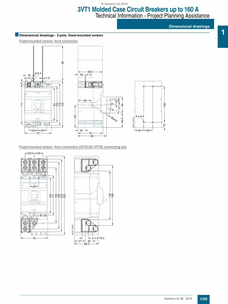
3VT1 Molded Case Circuit Breakers up to 160 ATechnical Information - Project Planning Assistance
Dimensional drawings
1/39Siemens LV 36 · 2014
1■ Dimensional drawings - 3-pole, fixed-mounted version
Fixed-mounted version, front connection
Fixed-mounted version, front connection (3VT9100-4TF30 connecting set)
1.5
Ø 6.4 68.5
40.5R54.6
TEST
OFF
ON
7
2575
93 100
111
118
130
98
25 2525
1218
8070
220
14°2°
13° 45
15
38
63
20
100
4 x Ø 4
NS
O0_
0001
8
2 x Ø 16.2
68.5
TEST
OFF
ON
75
100
111
154
186
202
220
2525
25
168
136
31 20
NS
O0_
0002
0
LV36_2014.book Seite 39 Freitag, 31. Januar 2014 4:36 16
© Siemens AG 2014

3VT1 Molded Case Circuit Breakers up to 160 ATechnical Information - Project Planning Assistance
Dimensional drawings
1/40 Siemens LV 36 · 2014
1 Fixed-mounted version, front connection (3VT9100-4ED30 connecting set)
Fixed-mounted version, rear connection (3VT9100-4RC30 connecting set)
36.5
37.537.5
Ø 10.5
TEST
OFF
ON
100
111
130
183
10
2025
25
75
20
422
2525
1510
0
4 x Ø 4
NS
O0_
0002
6
TEST
OFF
ON
75
25
25
25
35
111
100
130
12
80
70
4287
NS
O0_
0002
3
3
2
25 25
100
25
Ø 15
2 x Ø 4
9.5
Ø 6.4
Ø 1
3.2
5.5
LV36_2014.book Seite 40 Freitag, 31. Januar 2014 4:36 16
© Siemens AG 2014

3VT1 Molded Case Circuit Breakers up to 160 ATechnical Information - Project Planning Assistance
Dimensional drawings
1/41Siemens LV 36 · 2014
1Fixed-mounted version, rotary operating mechanism
Fixed-mounted version, rotary operating mechanism with adjustable knob
Dimensions of door cut-out
27.5
1 3VT1 2 3VT9100-3HA.0, -3HB.0 3 3VT9100-3HE.0, 3HF.0
22.5
22.5
TEST
45°90
°
75
98 29
63
1
23N
SO
0_00
029
27,5
22,5
22,5
TESTTEST
45°90
°
75
NS
O0_
0003
1
98
63
45
45
1
2
3 45
6
124 ... 448 (-3HJ10)297 ... 450 (-3HJ20)
1 3VT1 2 3VT9100-3HA.0, -3HB.03 3VT9100-3HJ.0 4 3VT9100-3HE.0, -3HF.05 3VT9100-3HG.0, -3HH.06 Outside surface of
cabinet door
min.50
ø6
ø37
32
32
NSO0_00553
LV36_2014.book Seite 41 Freitag, 31. Januar 2014 4:36 16
© Siemens AG 2014
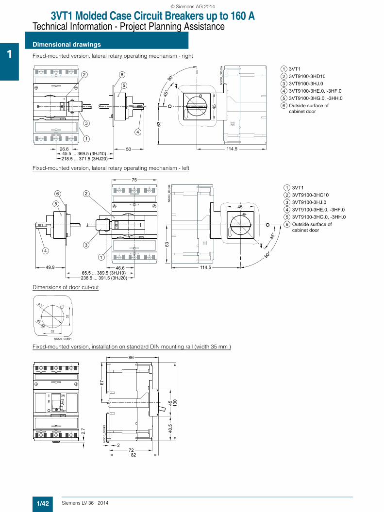
3VT1 Molded Case Circuit Breakers up to 160 ATechnical Information - Project Planning Assistance
Dimensional drawings
1/42 Siemens LV 36 · 2014
1 Fixed-mounted version, lateral rotary operating mechanism - right
Fixed-mounted version, lateral rotary operating mechanism - left
Dimensions of door cut-out
Fixed-mounted version, installation on standard DIN mounting rail (width 35 mm )
45.5 ... 369.5 (3HJ10)218.5 ... 371.5 (3HJ20)
26.6 114.5
NS
O0_
0003
5a
TEST
63
90°
45°
45
50
1
3
2 6
5
4
1 3VT1 2 3VT9100-3HD103 3VT9100-3HJ.0 4 3VT9100-3HE.0, -3HF.05 3VT9100-3HG.0, -3HH.06 Outside surface of
cabinet door
46.649.965.5 ... 389.5 (3HJ10)238.5 ... 391.5 (3HJ20)
114.5
NS
O0_
0003
6
75
63
90°
45°
45
TEST
14
5
6
3
21 3VT1 2 3VT9100-3HC103 3VT9100-3HJ.0 4 3VT9100-3HE.0, -3HF.05 3VT9100-3HG.0, -3HH.06 Outside surface of
cabinet door
NSO0_00554
32
32
ø37
ø6
2.7 40
.5
TEST
OFF
ON
27282
86
45
67
130
NS
O0_
0004
3
LV36_2014.book Seite 42 Freitag, 31. Januar 2014 4:36 16
© Siemens AG 2014

3VT1 Molded Case Circuit Breakers up to 160 ATechnical Information - Project Planning Assistance
Dimensional drawings
1/43Siemens LV 36 · 2014
1Fixed-mounted version and lateral motorized operating mechanism
130
150NSO0_00555
70
40.5
45
80
94.4
NSO0_00556
LV36_2014.book Seite 43 Freitag, 31. Januar 2014 4:36 16
© Siemens AG 2014

3VT1 Molded Case Circuit Breakers up to 160 ATechnical Information - Project Planning Assistance
Dimensional drawings
1/44 Siemens LV 36 · 2014
1 ■ Dimensional drawings - 4-pole, fixed-mounted version
Fixed-mounted version, front connection
Fixed-mounted version, front connection (3VT9100-4TF40 connecting set )
Fixed-mounted version, rear connection (3VT9100-4RC00 connecting set)
1.5Ø 6.4
68.5
40.5R54.6
TEST
OFF
ON
7
25 25100
93 100
111
118
130
98
25 2550
1218
8070
220
14°2°
13° 45
15
38
63
20
100
M3
NS
O0_
0001
4
9.5
Ø 6.4
Ø 1
3.2
5.5
TEST
OFF
ON
100
25
25
2525
100
35
111
12
80
70
4287
NS
O0_
0001
6
3
2
25 25 25
100
25
M3
Ø 15
80
9.5
87
42
35
111
12
ø6.4
ø13.
2 3
70 NS
O0_
0055
7
252525
100
130
25
100
100
130
111
M3
2
25
25
5.525 25
ø15
NSO0_00559
LV36_2014.book Seite 44 Freitag, 31. Januar 2014 4:36 16
© Siemens AG 2014

3VT1 Molded Case Circuit Breakers up to 160 ATechnical Information - Project Planning Assistance
Dimensional drawings
1/45Siemens LV 36 · 2014
1Fixed-mounted version, front rotary operating mechanism
Fixed version, front rotary operating mechanism with adjustable knob
Dimensions of door cut-out
Fixed-mounted version, lateral rotary operating mechanism - right
52.5
22.5
22.5
TEST
45°90
°
75100
NS
O0_
0002
8
98 29
63
1
23
1 3VT1 2 3VT9100-3HA.0, -3HB.0 3 3VT9100-3HE.0, 3HF.0
NS
O0_
0052
5
98
63
1
2
3 45
6
124 ... 448 (-3HJ10)297 ... 450 (-3HJ20)
22.5
22.5
45°90
°
52.5
100
45
45
1 3VT1 2 3VT9100-3HA.0, -3HB.03 3VT9100-3HJ.0 4 3VT9100-3HE.0, -3HF.05 3VT9100-3HG.0, -3HH.06 Outside surface of
cabinet door
min.50
ø6
ø37
32
32
NSO0 00553
62.5 49.926.645.5 ... 369.5 (3HJ10)218.5 ... 371.5 (3HJ20)
114.5
NS
O0_
0003
2
TEST
100
63
90°
45°
45
1
3
2 6
5
4
1 3VT1 2 3VT9100-3HD103 3VT9100-3HJ.0 4 3VT9100-3HE.0, -3HF.05 3VT9100-3HG.0, -3HH.06 Outside surface of
cabinet door
LV36_2014.book Seite 45 Freitag, 31. Januar 2014 4:36 16
© Siemens AG 2014

3VT1 Molded Case Circuit Breakers up to 160 ATechnical Information - Project Planning Assistance
Dimensional drawings
1/46 Siemens LV 36 · 2014
1Fixed-mounted version, lateral rotary operating mechanism - left
Dimensions of door cut-out
Fixed-mounted version, installation on a standard DIN mounting rail (width 35 mm )
Arrangement of circuit breaker/switch disconnectors with 3VT9100-8LA00 mechanical interlocking
46.649.9 37.565.5 ... 389.5 (3HJ10)238.5 ... 391.5 (3HJ20)
114.5N
SO
0_00
033a
TEST
100
63
90°
45°
45
14
5
6
3
23VT1 3VT9100-3HC103VT9100-3HJ.0 3VT9100-3HE.0, -3HF.03VT9100-3HG.0, -3HH.0
123456 Outside surface of
cabinet door
32
32
ø37
ø6
2.7 40
.5
TEST
OFF
ON
27282
86
45
67
130
NS
O0_
0003
8
NS
O0_
0003
9
TEST
148.2
LV36_2014.book Seite 46 Freitag, 31. Januar 2014 4:36 16
© Siemens AG 2014
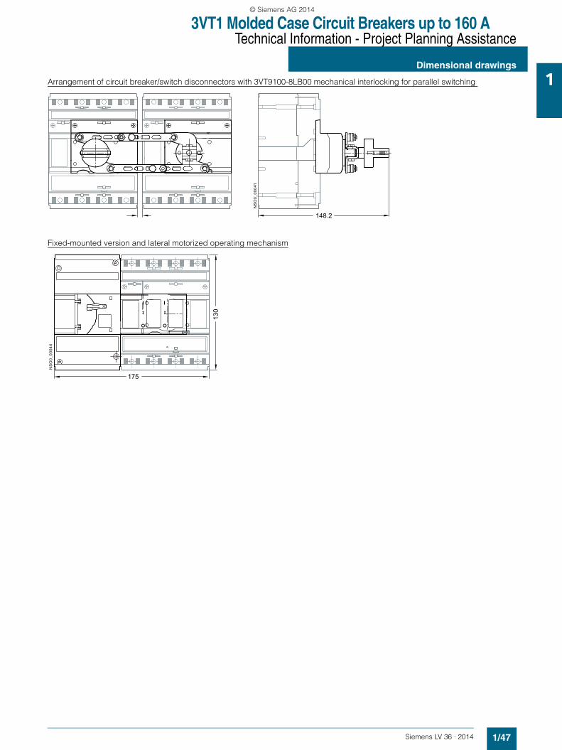
3VT1 Molded Case Circuit Breakers up to 160 ATechnical Information - Project Planning Assistance
Dimensional drawings
1/47Siemens LV 36 · 2014
1Arrangement of circuit breaker/switch disconnectors with 3VT9100-8LB00 mechanical interlocking for parallel switching
Fixed-mounted version and lateral motorized operating mechanismN
SO
0_00
041
T
148.2
NS
O0_
0004
4
TESTTEST
175
130
LV36_2014.book Seite 47 Freitag, 31. Januar 2014 4:36 16
© Siemens AG 2014

3VT1 Molded Case Circuit Breakers up to 160 ATechnical Information - Project Planning Assistance
Dimensional drawings
1/48 Siemens LV 36 · 2014
1 Fixed design, Residual current device, rear connection
Drilling diagram
Fixed design, Residual current device,bottom connection
181,
513
0
25 25 25 25 25100
25100
200
8070
3051
,5
130
80
40,5
45
1510
0
252525
M3
I201
_189
72
25
200
100
173
130
25 25 25100
25 25
8070
130
80
40,5
45
43
42,75,8
I201
_189
81
LV36_2014.book Seite 48 Freitag, 31. Januar 2014 4:36 16
© Siemens AG 2014