3PT Trimmer - m.media-amazon.com
20
MPN: 3PTTRIM SKU: 191441 3PT Trimmer Owner’s Manual
Transcript of 3PT Trimmer - m.media-amazon.com

MPN: 3PTTRIM
SKU: 191441
3PT Trimmer
Owner’s Manual

2
Table of Contents
General Warnings............................................................................................ 3
Controls and Features Identification ................................................................ 6
Specification .................................................................................................... 7
Assembly Instructions ..................................................................................... 7
Operation Instructions ................................................................................... 13
Maintenance and Storage ............................................................................. 14
Troubleshooting ............................................................................................. 16
Parts Drawing & Parts List ............................................................................. 17

3
GENERAL WARNINGS
READ and UNDERSTAND the manual completely before using 3-POINT HITCH
TRIMMER/MOWER.
Become familiar with the operation and service recommendations to ensure the best performance from
your machine.
DANGER YOUR 3-POINT HITCH TRIMMER is driven by a PTO shaft that transfers power from your Tractor. The
Tractor and PTO shaft are extremely dangerous and can cause serious injury or death if not used properly.
Read and understand all of the Warnings and operating instructions that came with your Tractor and the
PTO shaft to protect yourself from severe injury or death.
Safety for Children and Pets
WARNING Tragic accidents can occur if the operator is not alert to the presence of children and pets. Children are
often attracted to the machine and the trimming activity. Never assume that children will remain where you
last saw them. Always follow these precautions:
● Keep children and pets out of the working area and under the watchful care of a responsible adult.
● Be alert and turn the machine off if children or pets enter the work area.
● Never allow children to operate the 3-POINT HITCH TRIMMER/MOWER.
● Use extra care when approaching blind corners, shrubs, trees, or other objects that may obscure your
vision.
Protecting yourself and those around you
WARNING This is a high-powered machine, with moving parts operating with high energy at high speeds. You must
operate the machine safety. Unsafe operation can create a number of hazards for you, as well as anyone
else in the nearby area. Always take the following precautions when using this machine:
● Keep in mind that the operator or user is responsible for accidents or hazards occurring to other people,
their property, and themselves.
● Always wear protective goggles or safety glasses with side shields while trimming to protect your eyes
from possible thrown debris.

4
● Avoid wearing loose clothing or jewelry, which can catch on the machine’s moving parts.
● We recommend wearing gloves while using this machine. Be sure your gloves fit properly and do not
have loose cuffs or drawstrings.
● Wear shoes with non-slip treads when using your 3PT Trimmer. Safety shoes are recommended. Do
not use the machine while barefoot or wearing sandals with exposed toes or heels.
● Wear long pants while operating the 3PT Trimmer.
● Use ear protectors or ear plugs rated for at least 20 dba to protect your hearing.
● Keep bystanders at least 100 feet away from your work area at all times. The tips of the cutting cords
on the 3PT Trimmer can throw sticks, small stones, gravel, and bits of debris over long distances at
great velocity. Do not travel over loose materials such as gravel or mulch with the trimmer head
spinning. Doing so could cause injury or property damage from thrown objects. Disengage the PTO
shaft to stop the spinning cords and shut off the Tractor engine when another person or pet approaches.
● Never tamper with safety devices. Check their proper operation regularly.
● Never operate the machine when under the influence of alcohol, drugs, or medication.
Operating the Trimmer/mower Safety
WARNING This is a high-powered machine, with moving parts operating with high energy at high speeds. You must
operate the machine safely. Unsafe operation can create a number of hazards for you, as well as anyone
else in the nearby area. Always take the following precautions when using this machine:
● Do not have the Trimmer engaged or resting on the ground when backing up. The machine is designed
to trim and roll on the Wheel in the forward direction only. Trimming or rolling on the Wheel in the
reverse direction could damage the machine and is not covered by the Warranty.
● Know how to stop the Trimmer quickly by disengaging the PTO Shaft and shutting down the tractor.
● Never allow people who are unfamiliar with these instructions to use the 3PT Trimmer. Allow only
responsible individuals who are familiar with these rules of safe operation to use your machine.
● Do not exceed 2 mph when trimming to allow proper cutting and discharge of material.
● Do not exceed 7 mph when transporting to prevent damage to the machine.
● Operating your 3point trimmer with the head misaligned with the ground can result in poor cut quality,
pivoting problems, scalping during cutting, wear on your equipment, and damage to the cutting cord.
● Never place your hands, feet, or any part of your body on or under the mower deck in the path of the
spinning cords, belt, pulleys, or near the discharge opening while the tractor is running. Keep area of
discharge clear of people, animals, buildings, glass, or anything else that will obstruct clear discharge,
cause injury, or damage.
● Your 3PT Trimmer is a powerful tool, not a plaything. Exercise extreme caution at all times. The design
of your machine is for trimming and mowing grass, weeds, and other growth as specified in this manual.
Do not use it for any other purpose.
● Whenever you leave the operating position to make adjustments, change cords or if you have to
remove grass or debris from the underside of the deck, always disengage PTO, shut down the Tractor
Engine, remove the key, wait for all moving parts to come to a complete stop, disconnect the PTO shaft

5
from the Tractor, then wait five minutes before performing any maintenance procedure or inspection
on the Trimmer.
● Be mindful of hazards, changes in terrain, slopes, or wet conditions. Use care when backing up.
● Stop the cutting cords when crossing gravel drives, walks, or roads.
● Never, under any conditions, remove, bend, cut, fit, weld, or otherwise alter standard parts on the 3PT
Trimmer. This includes all shields and guards. Modifications to your machine could cause personal
injuries and property damage and will void your warranty.
● If the cutting cords strike a foreign object or if your machine should start making an unusual noise or
vibration, disengage PTO, shut down the Tractor Engine, remove the key, wait for all moving parts to
come to a complete stop, disconnect the PTO shaft from the Tractor, then wait five minutes before
inspection. Vibration is generally a sign of trouble. Clean and repair and/or replace damaged parts.
● While using the 3PT Trimmer, do not hurry or take things for granted. When in doubt about the
equipment or your surroundings, stop the machine and take the time to look things over. Make sure
that you have 100% control of the Trimmer at all times.
● Watch for traffic when mowing near roadways.
● Use the machine only in daylight.
● Be cautious when using your 3PT Trimmer around fencing, wires, ropes, and hoses. It is possible that
these and other debris can become wound around the Cord Head of the machine, potentially damaging
the bearings or injuring you.
● Do not operate the 3pT Trimmer on slopes greater than is recommended in you Tractor manual.
● Keep all nuts and bolts tight and keep the equipment in good operating condition.
A Note to All Users
No list of warnings and cautions can be all-inclusive. If situations occur that are not covered by this manual,
the operator must apply common sense and operate this 3PT Trimmer in a safe manner.

6
It may be helpful to familiarize yourself with the controls and features of your 3-POINT HITCH
TRIMMER/MOWER as shown in Figure 1 before beginning these procedures.
Controls and Features Identification

7
Tractor Requirements Category 1, 25 to 45 HP Max.
Drive Tractor PTO
PTO Speed 540 PRM
Number of Trimmer Cords 2
Belt A-2565 V-Belt
Belt Adjustment Spring Loaded Idler Pulley
Max. Wheel Base (distance from outside to
Outside of rear wheels)
80”
Cutting Height 5 Heights, 1.5” to 3.5”
Cutting Width 22”
Machine Weight 220LB
WARNING Before performing the following procedure, be sure your tractor engine is off, brake is set, and the key
removed for safety.
STEP 1: Attach the 3-point Bracket to the Tractor
1. Position the 3-point bracket at the rear of the tractor with the back plate facing away from the back of
the tractor. The opposite side of the 3-point bracket facing the upper draft arm is open.
2. Attach the 3-point bracket to the tractor and secure with drive pin.
Specifications
Assembly Instructions
8
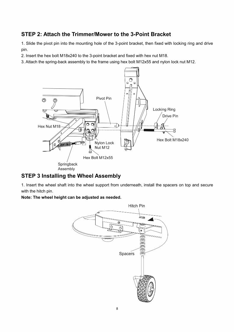
STEP 2: Attach the Trimmer/Mower to the 3-Point Bracket
1. Slide the pivot pin into the mounting hole of the 3-point bracket, then fixed with locking ring and drive
pin.
2. Insert the hex bolt M18x240 to the 3-point bracket and fixed with hex nut M18.
3. Attach the spring-back assembly to the frame using hex bolt M12x55 and nylon lock nut M12.
STEP 3 Installing the Wheel Assembly
1. Insert the wheel shaft into the wheel support from underneath, install the spacers on top and secure
with the hitch pin.
Note: The wheel height can be adjusted as needed.

9
STEP 4: Calculating length of PTO Shaft needed
The PTO Shaft provided with your Trimmer is 32” overall compressed length and will work “as is” for most
applications. Before you install the PTO shaft it is good practice to calculate optimum PTO shaft length
according to your tractor and usage needs to determine if modifications are needed.
WARNING The minimum recommended overlap of the tubes at the center of the PTO shaft should be 6”. Using a PTO
shaft with less than 6” overlap may fail and cause machine damage or personal injury.
Tools Needed:
● 13mm Wrench
● 4mm Allen Wrench
1. Slightly loosen the wing nut, rotate the gearbox guard up away from the gearbox shaft.
2. Attach the PTO shaft to the gearbox, put flat key in the middle of PTO shaft and gearbox, then tighten
set screw.
3. Press PTO spring pin and connect PTO shaft to the tractor spline shaft, then check whether the
assembly is in place. (The installation is complete when the spring pin will automatically rebound.)
4. Check the PTO both ends of the assembly in place, cover the gearbox guard.
Note: One side of PTO and gearbox sealing ring to keep 5MM distance, so as not to lead to a
collision with gearbox sealing ring.
STEP 5: Installing Trimmer Cords
Always make sure to install all four trimmer cords and ensure they are the same length. Not having all four

10
cords installed and/or at the same length will cause excessive vibration and could damage the machine.
1. Insert the end of a trimmer cord into the inlet hole (large slotted cutout) push it in until the end protrudes
out the other side approximately 10mm.
2. Turn the cord head 90 degrees and repeat the installation until all cords are installed.
Note: The cord can only move through the cord head in one direction. To remove it you must pull
it from the other side of the Holder (where the 10mm end is).
NOTICE Running the trimmer without all four cords installed or cords of unequal length can cause excessive
vibration and may damage the machine.

11
STEP 6: Cord Head Adjustment
Note: The cord head can be located above or below the molded spacer giving you a 1-1/2” range in
trimming height. The following steps show moving the cord head from below the molded spacer to on top
of the molded spacer.
1. Align the hole in the anti wrap canister with the internal
housing at the location shown.
2. Insert a Philips head screwdriver into the hole in the anti
wrap canister and the hole in the internal housing.
3. Rotate the plastic spherical cap until the screw driver
sliders into a hole in the shaft, locking it into place.
4. Looking down at the top of the Frame, turn the plastic
spherical cap clockwise until it unscrews completely from
the bearing housing.
Note: If the plastic spherical cap continues to turn, but does
not come off, check that you locked the screw driver into
the shaft. If the plastic spherical cap will not turn by hand a
9/16” Socket can be used on the belt (inside the bottom of
the plastic spherical cap) to loosen it. You may need to
clean grass or debris out of the recess first.
5. Slide the cord head, adapter and molded spacer off the
shaft.
6. The anti wrap can and spacer should remain on the shaft
with the screw driver.
7. Make sure the adapter is inserted into the top of the cord
head as you install the cord head onto the shaft.
8. Install the molded spacer onto the shaft.
9. Place the head of the hex bolt M8x25 so it is sitting inside
the hex cavity at the bottom of the plastic spherical cap.
10. Looking down at the top of the frame, hold the bolt head
in place with your finger and turn the plastic spherical cap
clockwise to start the bolt into the shaft.
11. Tighten the assembly securely by turning the plastic
spherical cap counterclockwise when looking down on the
top of the frame.
12. Remove the screw driver.

12
STEP 7: Greasing the Wheel Support
Tools needed:
● Flexible hose grease gun
● Lithium grease
● Clean cloth
Apply a quality general-purpose lithium grease with a hand-pumped grease gun to each of the support
grease fitting.
Support
Grease Fitting

13
WARNING ● This machine is designed to operate at 540 rpm PTO shaft speed only! Never operate at a faster speed;
doing so can cause serious injury to the operator or bystanders and could cause damage to the
machine that is not covered under warranty.
● Read and understand your tractor owner’s manual and all tractor safety warnings for operating your
tractor safety before operating this 3-Point Hitch Trimmer/Mower.
Operation Notes
● See the Owner’s manual that came with your tractor for all safety warnings and detailed information
for operating your tractor properly.
● Always operate the tractor PTO at 540 RPM when trimming.
● Always disengage the PTO, lock the parking brake and shut off the tractor when leaving the tractor
seat.
● Never transport the trimmer while the PTO is turning.
● Do not have the trimmer engaged or resting on the ground when backing up. The machine is designed
to trim and roll on the wheel in the forward direction only, Trimming or rolling on the wheel in the reverse
direction could damage the machine and is not covered by the warranty.
● Remove any debris buildup from the machine before every use of the trimmer.
● Always install the locking bolt and wing nut into the transport holes of the 3-Point bracket and trimmer
when transporting the trimmer.
Setting Wheel Height
1. Remove the Hitch clip and remove the wheel assembly with spacers.
2. Adjust the spacers as desired with some under and some above the support on the shaft.
3. Reinstall wheel assembly, spacers and hitch clip.
Note: More spacers under the support will lower the wheel and set the trimmer head higher. More spacers
on top of the support will raise the wheel and set the trimmer head lower.
Hitch Clip
Spacers
Support
Wheel Assembly
Operation Instructions

14
Engaging the Trimmer Head
1. Ensure that the trimmer is lowered to the ground and all guards are in place and properly secured before
using.
2. Set tractor throttle at IDLE and engage the PTO.
3. Increase tractor throttle to the RPM’s required to obtain 540 PTO speed.
Note: See your tractor manual for detailed information on tractor operation.
Stopping the Cords from Spinning
1. Reduce tractor throttle to IDLE.
2. Disengaging PTO to stop the trimmer.
Regular maintenance is the way to ensure the best performance and long life of your machine. Please
refer to this manual for maintenance procedures.
WARNING
Disengage PTO, shut down the tractor engine, remove the key, wait for all moving parts to come to a
complete stop, disconnect the PTO shaft from the tractor, then wait five minutes before performing any
maintenance procedure or inspection on the trimmer.
Regular Maintenance Checklist
Note: Consider that the service intervals shown are the maximum under normal operating conditions.
Increase frequencies under extremely dirty or dust conditions. See the owner’s manual that came with the
tractor and with the PTO shaft for specific tractor and PTO shaft maintenance.
PROCEDURE
BEFORE
EACH USE
EVERY 8-10
HOURS
EVERY 18-20
HOURS
EVERY 50
HOURS
EVERY 100
HOURS
Check general equipment
condition,e.g. nuts, bolts, welds,etc. ●
Replace broken of frayed cutting
cords. ●
Check the plastic spherical cap and
cord head for excessive wear. ●
Lubricate PTO shaft and wheel
support grease fittings ●
Check belt tension and condition ●
Lubricate PTO shaft spline ends and
center overlap ●
Replace the belt ●
Grease pivot bearings and gearbox ●
Maintenance and Storage

15
Maintenance Position
Many maintenance procedures can be performed easier by positioning the trimmer in an upright
“maintenance” position. This position is for maintenance purposes only. Do not transport or operate the
trimmer in the upright position.
WARNING ● Two people are required when setting the trimmer body to the maintenance position. One person must
steady the trimmer as the other installs the bolt. Do not allow the trimmer body to go beyond vertical
and fall in the opposite direction without the bolt in place as this could cause injury to you or damage
the trimmer.
● Never transport the trimmer in the “Maintenance” position. This could damage the machine and is not
covered by the warranty.
1. Remove the bolt and wing nut that is holding the trimmer in the trimming operating positions.
2. Lift the trimmer body up to a vertical position. With the head of the bolt facing the tractor, install the bolt
all the way into the transport hole of the 3-point bracket.
3. Let the trimmer mounting bracket rest against the bolt to hold it in the vertical (maintenance) position.
STORAGE
Before storing make sure the trimmer is clean and dry for years of trouble free service.
Lightly lubricate all trimmer surfaces and moving parts to prevent rust.
Store indoors or protected area during severe weather and winter months.

16
Most problems are easy to fix. Consult the troubleshooting table below for common problems and their
solutions.
WARNING
Disengage PTO, shut down the tractor engine, remove the key, wait for all moving parts to come to a
complete stop, disconnect the PTO shaft from the tractor, then wait five minutes before performing any
maintenance procedure or inspection on the trimmer.
SYMPTOM POSSIBLE CAUSE
Poor cut quality 1. Cord need to be replaced.
2. Tractor speed too fast.
Scalping 1. Arm or wheel adjustment is off. Check for frame level or height
of hydraulic arms on tractor
Machine stops cutting 1. Inspect cords.
2. Check belt tension/wear.
3. Check PTO rotation
The trimmer head
won’t spin or lacks
power
1. Check for proper alignment of the V-belt.
2. The belt may be worn or frayed; if so, replace it.
Troubleshooting

17
Parts Drawing & Parts List

18
Ref# Drawing No. Description Qty
1 TS600-02000 Base 1
2 9604-30305 Single Row Taper Roller Bearing 2
3 TS600-00003 Spacer B 1
4 TS600-00004 Articulating Bracket A 1
5 TS600-00005 Articulating Bracket B 1
6 9101-10040-DX8.8 Hex Bolt M10x40 8
7 9301-1000-DX Flat Washer Ø10 8
8 TS6000-03000 Gearbox Fixed Frame 2
9 9215-10000-DX8.8 Hex Flange Lock Nut M10 35
10 TS600-01000 3-Point Bracket 1
11 TS600-00006 Nylon Sleeve 2
12 TS600-00007 Fixing Ring 1
13 T400-40000-DX Drive Pin 4
14 N800-00003-DX Hitch Pin 2
15 9306-22000-DX Lock Washer Ø22 2
16 9301-22000-DX Flat Washer Ø22 2
17 9206-22000-DC Hex Nut M22 2
18 9101-10040-8.8Q Hex Bolt M10x40 1
19 9101-18240-DX8.8 Hex Bolt M8x240 1
20 9201-18000-DX Hex Nut M8 1
21 SMP700-06000 PTO Shaft 1
22 TS600-06000 Linch Pin 1
23 TS600-00009 Frame 1
24 TS600-09000 Pivot Support Shaft 1
25 TS600-08000 Gearbox 1
26 TS600-04000 Gearbox Guard 1
27 TS600-04002 Bushing 2
28 9101-10180-DX8.8 Hex Bolt M10x180 2
29 9302-10000-DX Big Flat Washer Ø10 21
30 9208-10000-8.8DX Wing Nut M10 1
Parts Drawing & Parts List

19
Ref# Drawing No. Description Qty
31 9101-10125-8.8DX Hex Bolt M10x125 2
32 Flat Key 8x7x32 2
33 9101-10025-DX Hex Bolt M10x25 22
34 TS600-00010 Spring Holder Base 1
35 TS600-13000 Belt Adjustment Plate 1
36 9101-10065-8.8Q Hex Bolt M10x65 1
37 9206-10000-DX8.8 Hex Lock Nut M10
38 TS600-00008 Pulley Ø190 1
39 TS600-07000 Rotor Bearing 1
40 9603-6203-2RS Deep Groove Ball Bearing 6203-2RS 2
41 9309-40000-FH Circlip for Hole Ø40 1
42 TS600-00011 Shaft 1
43 TS600-00002 Pulley Ø77 1
44 Flat Key 5x5x20 1
45 9302-06000-DX Big Flat Washer Ø6 10
46 9101-01016-DX8.8 Hex Bolt M6x16 10
47 9302-08000-DX Big Flat Washer Ø8 4
48 6215-08000-DX8.8 Hex Flange Lock Nut M8 10
49 TS600-12000-DX Wheel Axle Spacer 1
50 9010-08020 Hex Bolt M8x20 6
51 TS600-00012 Adapter 1
52 TS600-00013 Spacer 1
53 TS600-00014 Anti Wrap Can 1
54 TS600-00015 Briquetting A 1
55 TS600-00016 Molded Spacer 1
56 TS600-00017 Plastic Spherical Cap 1
57 TS600-00018 Briquetting B 1
58 TS600-00019 Briquetting C 1
59 TS600-11000 Barb 4
60 TS600-00021 Pressure Spring 4
Parts Drawing & Parts List

20
Ref# Drawing No. Description Qty
61 9103-05024-DX8.8 Hex Socket Countersunk Head Screw M5x24 4
62 TS600-00001 Hex Bolt M8x25 1
63 TS600-06000 Deflector Guard 1
64 9101-08030-DX8.8 Hex Bolt M8x30 4
65 TS600-00022 Connecting Plate 2
66 TS600-05000 Wheel Stand 1
67 9701-06000 Oil Cup 1
68 TS600-00023 Nylon Bushing 2
69 TS600-10000 Wheel Caster 1
70 TS600-00024 Spacer 6
71 TS600-14000 Pneumatic Wheel 1
72 9404-04040-DX Cotter Pin 4x40 2
73 TS600-00025 Cutting Cord 2
74 TS600-00026 Nylon Loop 2
75 V-Belt A-2565 1
76 TS600-00020 Belt Cover 1
77 TS600-12000 Small Belt Cover 1
78 TS600-15000 Springback Assembly 1
79 9101-12055-DX8.8 Hex Bolt M12x55 1
80 9206-12000-DX Nylon Lock Nut M12 1
81 9312-25000-FH Wire Snap Ring for Shaft Ø25 1
82 LSP25-00020-FH Hex Slotted Thin Nut M20x1.5 1
83 939903-08000-DX Big Flat Washer Ø8 1
84 9010-08015 Hex Bolt M8x15 1
85 N800-00004-DX Hitch Pin 2
Parts Drawing & Parts List
![INDEX [m.media-amazon.com]](https://static.fdocuments.net/doc/165x107/61b40d21a734852bc16b684a/index-mmedia-.jpg)