3G Americas Research HSPA-LTE Advanced
132
-
Upload
amit-chakradeo -
Category
Documents
-
view
857 -
download
2
description
Transition to 4G 3GPP Broadband evolution to IMT-Advanced
Transcript of 3G Americas Research HSPA-LTE Advanced


Transition to 4G: 3GPP Broadband Evolution to IMT-Advanced, Rysavy Research/3G Americas, Sept 2010 Page 2
TABLE OF CONTENTS INTRODUCTION ......................................................................................................... 4 BROADBAND TRENDS ................................................................................................ 6
Transition to 4G ...................................................................................................... 7 Wireless versus Wireline Advances ............................................................................. 9 Bandwidth Management Trends ............................................................................... 10 Mobile Broadband Cost and Capacity Trends .............................................................. 11
WIRELESS DATA MARKET ........................................................................................ 12 Market Trends ....................................................................................................... 12 EDGE/HSPA/HSPA+/LTE Deployment ........................................................................ 14 Statistics .............................................................................................................. 15
WIRELESS TECHNOLOGY EVOLUTION ..................................................................... 16 3GPP Evolutionary Approach ................................................................................... 16 Spectrum ............................................................................................................. 20 Core-Network Evolution .......................................................................................... 23 Service Evolution ................................................................................................... 23 Voice Support ....................................................................................................... 24 Device Innovation .................................................................................................. 25 Network Interfaces for Applications .......................................................................... 25 Mobile Application Architectures ............................................................................... 27 Broadband-Wireless Deployment Considerations ........................................................ 27 Data Offload ......................................................................................................... 28 Feature and Network Roadmap ................................................................................ 29 Deployment Scenarios ............................................................................................ 32
COMPETING TECHNOLOGIES ................................................................................... 34 CDMA2000 ........................................................................................................... 34 WiMAX ................................................................................................................. 36 Municipal Wi-Fi Systems ......................................................................................... 39
COMPARISON OF WIRELESS TECHNOLOGIES .......................................................... 39 Data Throughput ................................................................................................... 40 HSDPA Throughput in Representative Scenarios ......................................................... 43 Release 99 and HSUPA Uplink Performance ............................................................... 45 HSPA+ Throughput ................................................................................................ 46 LTE Throughput ..................................................................................................... 47 Latency ................................................................................................................ 50 Spectral Efficiency ................................................................................................. 51 Cost, Volume, and Market Comparison ..................................................................... 60 Competitive Summary ............................................................................................ 62
CONCLUSION ........................................................................................................... 64 APPENDIX: TECHNOLOGY DETAILS ......................................................................... 66
Spectrum Bands .................................................................................................... 67 EDGE/EGPRS ........................................................................................................ 68 Evolved EDGE ....................................................................................................... 71 UMTS-HSPA Technology ......................................................................................... 78 UMTS Release 99 Data Capabilities ........................................................................... 80 HSDPA ................................................................................................................. 81

Transition to 4G: 3GPP Broadband Evolution to IMT-Advanced, Rysavy Research/3G Americas, Sept 2010 Page 3
HSUPA ................................................................................................................. 84 Evolution of HSPA (HSPA+) ..................................................................................... 85 HSPA Voice Support ............................................................................................... 96 3GPP LTE ............................................................................................................. 98 4G, IMT-Advanced and LTE-Advanced ..................................................................... 108 UMTS TDD .......................................................................................................... 112 TD-SCDMA ......................................................................................................... 113 IMS ................................................................................................................... 113 Heterogeneous Networks and Self Optimization ....................................................... 114 Broadcast/Multicast Services ................................................................................. 116 EPC ................................................................................................................... 117 White Space ....................................................................................................... 120
ABBREVIATIONS ................................................................................................... 121 ADDITIONAL INFORMATION ................................................................................. 127 REFERENCES ......................................................................................................... 127

Transition to 4G: 3GPP Broadband Evolution to IMT-Advanced, Rysavy Research/3G Americas, Sept 2010 Page 4
Introduction Over the past year, the promise of mobile broadband has become reality as many tens of millions of users have actively started using smartphones, tablets, netbooks, and laptops with wireless connections. Yet, we are only scratching the surface of what is to come. This will be the decade of “anywhere” social existence, work, and entertainment.
Major developments this past year include 3rd Generation (3G) ubiquity, deepening smartphone capability, the availability of hundreds of thousands of mobile applications, the introduction of new form factors such as tablets, projections of mobile-data demand exceeding capacity, acknowledgment by industry and government of the need for more spectrum, implementation of data offload via Wi-Fi, dramatic performance increases through HSPA enhancements, initial deployments of LTE technology, and significant progress on specifications that will meet “true” Fourth Generation (4G) requirements.
3G technology has shown us the power and potential of always-on, everyplace network connectivity and has ignited a massive wave of industry innovation that spans devices, applications, Internet integration, and new business models. Already used by hundreds of millions of people, mobile broadband connectivity is on the verge of becoming ubiquitous. It will do so on a powerful foundation of networking technologies including Global System for Mobile Communications (GSM) with Enhanced Data Rates for GSM Evolution (EDGE), High Speed Packet Access (HSPA), and Long Term Evolution (LTE). LTE in a forthcoming release called LTE-Advanced will be one of the first technologies to meet the requirements of International Mobile Telecommunications Advanced (IMT-Advanced), a project of the International Telecommunications Union (ITU).
Through constant innovation, Universal Mobile Telecommunications System (UMTS) with HSPA technology has established itself as the global, mobile-broadband solution. Building on the phenomenal success of GSM, the GSM-HSPA ecosystem has become the most successful communications technology family ever. Through a process of constant improvement, the GSM family of technologies has not only matched or exceeded the capabilities of all competing approaches, but has significantly extended the life of each of its member technologies.
HSPA is strongly positioned to be the dominant mobile-data technology for the next five to ten years. To leverage operator investments in HSPA, the Third Generation Partnership Project (3GPP) standards body has developed a series of enhancements to create “HSPA Evolution,” also referred to as “HSPA+.” HSPA+ represents a logical development of the Wideband Code Division Multiple Access (WCDMA) approach, and it is the stepping stone to an entirely new 3GPP radio platform called 3GPP LTE. LTE, which uses Orthogonal Frequency Division Multiple Access (OFDMA), is seeing initial deployment this year. Simultaneously, 3GPP—recognizing the significant worldwide investments in GSM networks—has defined enhancements that will significantly increase EDGE data capabilities through an effort called Evolved EDGE.
Combined with these improvements in radio-access technology, 3GPP has also spearheaded the development of major core-network architecture enhancements such as the IP Multimedia Subsystem (IMS) and the Evolved Packet Core (EPC), previously called System Architecture Evolution (SAE). These developments will facilitate new types of services, the integration of legacy and new networks, the convergence of fixed and wireless systems, and the transition from circuit-switched approaches for voice traffic to a fully packet-switched model.
The result is a balanced portfolio of complementary technologies that covers both radio-access and core networks, provides operators maximum flexibility in how they enhance their networks over time, and supports both voice and data services.

Transition to 4G: 3GPP Broadband Evolution to IMT-Advanced, Rysavy Research/3G Americas, Sept 2010 Page 5
This paper discusses the evolution of EDGE, HSPA enhancements, 3GPP LTE, the capabilities of these technologies, and their position relative to other primary competing technologies. It explains how these technologies fit into the ITU roadmap that leads to IMT-Advanced. The following are some of the important observations and conclusions of this paper:
The wireless technology roadmap now extends to IMT-Advanced with LTE-Advanced being one of the first technologies defined to meet IMT-Advanced requirements. LTE-Advanced will be capable of peak throughput rates that exceed 1 gigabit per second (Gbps).
Future networks will be networks of networks, consisting of multiple-access technologies, multiple bands, widely-varying coverage areas, all self-organized and self-optimized.
GSM-HSPA1 has an overwhelming global position in terms of subscribers, deployment, and services. Its success will continue to marginalize other wide-area wireless technologies.
In current deployments, HSPA users regularly experience throughput rates well in excess of 1 megabit per second (Mbps) under favorable conditions, on both downlinks and uplinks, with 4 Mbps downlink speed commonly being measured. Planned enhancements such as dual-carrier operation will double peak user-achievable throughput rates.
HSPA+ provides a strategic performance roadmap advantage for incumbent GSM-HSPA operators. Features such as multi-carrier operation, Multiple Input Multiple Output (MIMO), and higher-order modulation offer operators multiple options for upgrading their networks, with many of these features (e.g., multi-carrier, higher-order modulation) being available as network software upgrades. With all planned features implemented, HSPA+ peak rates will eventually reach 168 Mbps.
HSPA+ with 2x2 MIMO, successive interference cancellation, and 64 Quadrature Amplitude Modulation (QAM) is more spectrally efficient than competing technologies including Worldwide Interoperability for Microwave Access (WiMAX) Release 1.0.
The 3GPP OFDMA approach used in LTE matches or exceeds the capabilities of any other OFDMA system. Peak theoretical downlink rates are 326 Mbps in a 20 MHz channel bandwidth. LTE assumes a full Internet Protocol (IP) network architecture, and it is designed to support voice in the packet domain.
LTE has become the technology platform of choice as GSM-UMTS and Code Division Multiple Access (CDMA)/One Carrier Evolved, Data Optimized (EV-DO) operators are making strategic, long-term decisions on their next-generation platforms.
GSM-HSPA will comprise the overwhelming majority of subscribers over the next five to ten years, even as new wireless technologies are adopted. The deployment of LTE and its coexistence with UMTS-HSPA will be analogous to the deployment of UMTS-HSPA and its coexistence with GSM.
3GPP has made significant progress on how to enhance LTE to meet the requirements of IMT-Advanced in a project called LTE-Advanced. LTE-Advanced is expected to be the first true 4G system available. Specifications are scheduled to be completed in March of 2011, with earliest availability for deployment in 2012.
HSPA-LTE has significant economic advantages over other wireless technologies. 1 This paper’s use of the term “GSM-HSPA” includes GSM, EDGE, UMTS, HSPA and HSPA+. “UMTS-HSPA” refers to UMTS technology deployed in conjunction with HSPA capability.

Transition to 4G: 3GPP Broadband Evolution to IMT-Advanced, Rysavy Research/3G Americas, Sept 2010 Page 6
WiMAX has developed an ecosystem supported by many companies, but it will still represent only a very small percentage of wireless subscribers over the next five years.
EDGE technology has proven extremely successful and is widely deployed on GSM networks globally. Advanced capabilities with Evolved EDGE can double and eventually quadruple current EDGE throughput rates, halve latency, and increase spectral efficiency.
EPC will provide a new core network that supports both LTE and interoperability with legacy GSM-UMTS radio-access networks and non-3GPP-based radio access networks. Policy-based charging and control provides flexible quality-of-service management, enabling new types of applications, as well as billing arrangements.
Innovations such as EPC and UMTS one-tunnel architecture will “flatten” the network, simplifying deployment and reducing latency.
This paper begins with an overview of the market, looking at trends, EDGE and UMTS-HSPA deployments, and market statistics. It then examines the evolution of wireless technology, particularly 3GPP technologies, including spectrum considerations, core-network evolution, broadband-wireless deployment considerations, and a feature and network roadmap. Next, the paper discusses other wireless technologies including Code Division Multiple Access 2000 (CDMA2000) and WiMAX. Finally, it compares the different wireless technologies technically, based on features such as performance and spectral efficiency.
The appendix explains in detail the capabilities and workings of the different technologies including EDGE, Evolved EDGE, WCDMA2, HSPA, HSPA+, LTE, IMT-Advanced, LTE- Advanced, IMS, and EPC.
Broadband Trends Broadband communication is becoming a foundational element of the entire economy, supporting entire industries, and is transforming the nature of human life itself. As reported in Morgan Stanley’s “Internet Trends” Report of June 2010, in a survey among the hierarchy of human needs, voice and data connectedness now ranks third, behind food and shelter.
As wireless technology represents an increasing portion of the global communications infrastructure, it is important to understand overall broadband trends. Sometimes wireless and wireline technologies compete with each other, but, in most instances, they are complementary. For the most part, backhaul transport and core infrastructure for wireless networks are based on wireline approaches, whether optical or copper. This applies as readily to Wi-Fi networks as it does to cellular networks.
Trends show explosive bandwidth growth of the Internet at large and for mobile broadband networks in particular. Cisco projects global IP traffic growing at a compound annual growth rate of 38% between 2009 and 2014, quadrupling traffic in that period. Mobile broadband traffic will grow at a CAGR of 108 percent in that same period.3
With declining voice revenue, but increasing data revenue, cellular operators face a tremendous opportunity in continuing to develop their mobile broadband businesses. Successful execution, however, means more than just providing high speed networks. It also 2 Although many use the terms “UMTS” and “WCDMA” interchangeably, in this paper we use “WCDMA” when referring to the radio interface technology used within UMTS and “UMTS” to refer to the complete system. HSPA is an enhancement to WCDMA. 3 Source: Cisco, “Hyperconnectivity and the Approaching Zettabyte Era,” June 2, 2010.

Transition to 4G: 3GPP Broadband Evolution to IMT-Advanced, Rysavy Research/3G Americas, Sept 2010 Page 7
means nurturing an application ecosystem, providing complementary services, and supplying attractive devices. These are all areas in which the industry has done well. This section discusses the transition to 4G, wireless versus wireline capabilities, bandwidth management, and trends in the cost of delivering mobile broadband.
Transition to 4G There is some confusion in the industry as to what technology falls into which cellular generation. 1G refers to analog cellular technologies; it became available in the 1980s. 2G denotes initial digital systems, introducing services such as short messaging and lower speed data. CDMA2000 1xRTT and GSM are the primary 2G technologies, although CDMA2000 1xRTT is sometimes called a 3G technology because it meets the 144 kbps mobile throughput requirement. EDGE, however, also meets this requirement. 2G technologies became available in the 1990s.
3G requirements were specified by the ITU as part of the International Mobile Telephone 2000 (IMT-2000) project, for which digital networks had to provide 144 kbps of throughput at mobile speeds, 384 kbps at pedestrian speeds, and 2 Mbps in indoor environments. UMTS-HSPA and CDMA2000 EV-DO are the primary 3G technologies, although recently WiMAX was also designated as an official 3G technology. 3G technologies began to be deployed last decade.
The ITU has recently issued requirements for IMT-Advanced, which constitutes the official definition of 4G. Requirements include operation in up-to-40 MHz radio channels and extremely high spectral efficiency. The ITU recommends operation in up-to-100 MHz radio channels and peak spectral efficiency of 15 bps/Hz, resulting in a theoretical throughput rate of 1.5 Gbps. Previous to the publication of the requirements, 1 Gbps was frequently cited as a 4G goal.
No available technology meets these requirements yet. It will require new technologies such as LTE-Advanced (with work already underway) and IEEE 802.16m. Some have tried to label current versions of WiMAX and LTE as “4G”, but this is only accurate to the extent that such designation refers to the general approach or platform that will be enhanced to meet the 4G requirements.
With WiMAX and HSPA significantly outperforming 3G requirements, calling these technologies 3G clearly does not give them full credit, as they are a generation beyond current technologies in capability. But calling them 4G is not correct. Unfortunately, the generational labels do not properly capture the scope of available technologies and have resulted in some amount of market confusion.
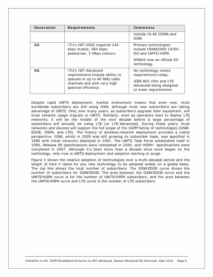
Table 1 summarizes the generations of wireless technology.
Table 1: 1G to 4G
Generation Requirements Comments
1G No official requirements.
Analog technology.
Deployed in the 1980s.
2G No official requirements.
Digital Technology.
First digital systems.
Deployed in the 1990s.
New services such as SMS and low-rate data.
Primary technologies
Transition to 4G: 3GPP Broadband Evolution to IMT-Advanced, Rysavy Research/3G Americas, Sept 2010 Page 8
Generation Requirements Comments
include IS-95 CDMA and GSM.
3G ITU’s IMT-2000 required 144 kbps mobile, 384 kbps pedestrian, 2 Mbps indoors
Primary technologies include CDMA2000 1X/EV-DO and UMTS-HSPA.
WiMAX now an official 3G technology.
4G ITU’s IMT-Advanced requirements include ability to operate in up to 40 MHz radio channels and with very high spectral efficiency.
No technology meets requirements today.
IEEE 802.16m and LTE Advanced being designed to meet requirements.
Despite rapid UMTS deployment, market momentum means that even now, most worldwide subscribers are still using GSM, although most new subscribers are taking advantage of UMTS. Only over many years, as subscribers upgrade their equipment, will most network usage migrate to UMTS. Similarly, even as operators start to deploy LTE networks, it will be the middle of the next decade before a large percentage of subscribers will actually be using LTE (or LTE-Advanced). During these years, most networks and devices will support the full scope of the 3GPP family of technologies (GSM-EDGE, HSPA, and LTE). The history of wireless-network deployment provides a useful perspective. GSM, which in 2009 was still growing its subscriber base, was specified in 1990 with initial networks deployed in 1991. The UMTS Task Force established itself in 1995, Release 99 specifications were completed in 2000, and HSPA+ specifications were completed in 2007. Although it’s been more than a decade since work began on the technology, only now is UMTS deployment and adoption starting to surge.
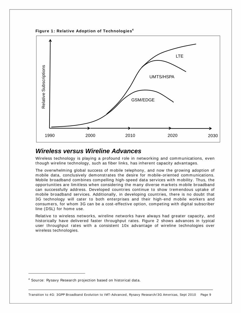
Figure 1 shows the relative adoption of technologies over a multi-decadal period and the length of time it takes for any new technology to be adopted widely on a global basis. The top line shows the total number of subscribers. The GSM/EDGE curve shows the number of subscribers for GSM/EDGE. The area between the GSM/EDGE curve and the UMTS/HSPA curve is for the number of UMTS/HSPA subscribers, and the area between the UMTS/HSPA curve and LTE curve is the number of LTE subscribers.
Transition to 4G: 3GPP Broadband Evolution to IMT-Advanced, Rysavy Research/3G Americas, Sept 2010 Page 9
Figure 1: Relative Adoption of Technologies4
Wireless versus Wireline Advances Wireless technology is playing a profound role in networking and communications, even though wireline technology, such as fiber links, has inherent capacity advantages.
The overwhelming global success of mobile telephony, and now the growing adoption of mobile data, conclusively demonstrates the desire for mobile-oriented communications. Mobile broadband combines compelling high-speed data services with mobility. Thus, the opportunities are limitless when considering the many diverse markets mobile broadband can successfully address. Developed countries continue to show tremendous uptake of mobile broadband services. Additionally, in developing countries, there is no doubt that 3G technology will cater to both enterprises and their high-end mobile workers and consumers, for whom 3G can be a cost-effective option, competing with digital subscriber line (DSL) for home use.
Relative to wireless networks, wireline networks have always had greater capacity, and historically have delivered faster throughput rates. Figure 2 shows advances in typical user throughput rates with a consistent 10x advantage of wireline technologies over wireless technologies.
4 Source: Rysavy Research projection based on historical data.
1990 2000 20202010
LTE
UMTS/HSPA
Re
lativ
e S
ub
scri
ptio
ns
GSM/EDGE
2030

Transition to 4G: 3GPP Broadband Evolution to IMT-Advanced, Rysavy Research/3G Americas, Sept 2010 Page 10
Figure 2: Wireline and Wireless Advances
Despite some of the inherent limitations of wireless technology relative to wireline, its fundamental appeal of providing access from anywhere has not constrained market growth. As the decade progresses, the lines between wireline and wireless networks will blur. The fact is that wireless networks are mostly wireline in their infrastructure. If an LTE picocell is serving a small number of houses using fiber backhaul, is this a wireline or wireless network? The answer is both.
Bandwidth Management Trends Given huge growth in usage, mobile operators are either employing or considering multiple approaches to manage bandwidth:
More spectrum. Spectrum correlates directly to capacity, and more spectrum is becoming available globally for mobile broadband.
Increased spectral efficiency. Newer technologies are spectrally more efficient, meaning greater throughput in the same amount of spectrum.
More cell sites. Smaller cell sizes result in more capacity per subscriber.
Femtocells. Femtocells can significantly offload the macro network. Pricing plans can encourage users to move high-bandwidth activities (e.g., movie downloads) to femtocell connections.
Wi-Fi. Wi-Fi networks offer another means of offloading heavy traffic.
Off-peak hours. Operators can offer lower rates or perhaps fewer restrictions on large data transfers that occur at off-peak hours such as overnight.
20102000 2005
100 kbps
10 kbps
1 Mbps
10 Mbps
100 Mbps
GPRS 40 kbps
UMTS 350 kbps
HSDPA 1 Mbps
HSPA+ 5 Mbps
LTE 10 Mbps
EDGE 100 kbps
ADSL 1 Mbps
ISDN 128 kbps
ADSL 3 to 5 Mbps
ADSL2+ 25 Mbps
FTTH 100 Mbps

Transition to 4G: 3GPP Broadband Evolution to IMT-Advanced, Rysavy Research/3G Americas, Sept 2010 Page 11
Quality of service (QoS). By prioritizing traffic, large downloads can occur with lower priority, thus not affecting other active users.
Innovative data plans. Creative new data plans influencing consumption behavior, including tiered pricing, could make usage affordable for most users, but could discourage excessive or abusive use.
It will take a creative blend of all of the above to make the mobile broadband market successful and to enable it to exist as a complementary solution to wired broadband.
Mobile Broadband Cost and Capacity Trends While the cost of delivering data with wireless broadband remains higher than with wireline broadband, costs continue to decline rapidly. One vendor has calculated that in a blended HSPA/LTE network that costs could go below 1 Euro per gigabyte (GByte) once penetration of mobile broadband reaches 40% and usage reaches 2 GByte per month.5
Figure 3: Operator CAPEX+OPEX Cost to Deliver a GByte of Data
3GPP technologies clearly address proven market needs; hence their overwhelming success. The 3GPP roadmap, which anticipates continual performance and capacity improvements, provides the technical means to deliver on proven business models. As the applications for mobile broadband continue to expand, HSPA, HSPA+, LTE and LTE-Advanced will continue to provide a competitive platform for tomorrow’s new business opportunities.
5 Source: Nokia Siemens Networks white paper, “Mobile Broadband with HSPA and LTE – Capacity and Cost Aspects,” 2010. Refer to the white paper for assumptions used.

Transition to 4G: 3GPP Broadband Evolution to IMT-Advanced, Rysavy Research/3G Americas, Sept 2010 Page 12
Wireless Data Market By June 2010, more than 4.4 billion subscribers were using GSM-HSPA6—nearly two-thirds of the world’s total 6.8 billion population.7 By the end of 2014, the global 3G wireless market is expected to include more than 3.3 billion subscribers of whom 2.7 billion will use 3GPP technologies, representing 87% market share.8 Clearly, GSM-HSPA has established global dominance. Although voice still constitutes most cellular traffic, wireless data worldwide now comprises a significant percentage of average revenue per user (ARPU). In the United States, wireless data exceeds 30% of ARPU on average and is likely to reach 35% by the end of 2010.9
This section examines trends and deployment, and then provides market data that demonstrates the rapid growth of wireless data.
Market Trends As stated in a Rysavy Research report for the Cellular Telephone Industries Association (CTIA) on mobile broadband spectrum demand,”We are at a unique and pivotal time in history, in which technology capability, consumer awareness and comfort with emerging wireless technology and industry innovation are converging to create mass-market acceptance of mobile broadband.”10
As data constitutes a rising percentage of total cellular traffic, it is essential that operators deploy spectrally efficient data technologies that meet customer requirements for performance—especially because data applications can demand significantly more network resources than traditional voice services. Operators have a huge investment in spectrum and in their networks; data services must leverage these investments. It is only a matter of time before today’s more than 4 billion cellular customers start taking full advantage of data capabilities. The EDGE/HSPA/LTE evolutionary paths provide data capabilities that address market needs and deliver ever-higher data throughputs, lower latency, and increased spectral efficiency.
As a consequence, this rich network and device environment is spawning the availability of a wide range of wireless applications and content. Because of its growing size—and its unassailable potential—application and content developers are making the wireless market a high priority.
Based on one leading UMTS-HSPA infrastructure vendor’s statistics, Figure 4 compares the rapid growth in wireless data traffic compared to voice traffic across multiple operators. By the end of 2009, in HSPA coverage areas worldwide, the volume of data traffic significantly exceeded voice traffic, with data usage actually accelerating. Operators that are the most aggressive with mobile broadband services are experiencing data growth rates even higher than these average values.
6 Source: “World Cellular Information Service,” Informa Telecoms & Media, June 2010. 7 Source: US Census Bureau, http://www.census.gov/ipc/www/idb/worldpopinfo.html. 8 Source: “World Cellular Information Service,” Informa Telecoms & Media, June 2010 9 Chetan Sharma, US Wireless Data Market Update - Q1 2010. 10 Source: Rysavy Research, “Mobile Broadband Spectrum Demand,” December 2008.

Transition to 4G: 3GPP Broadband Evolution to IMT-Advanced, Rysavy Research/3G Americas, Sept 2010 Page 13
Figure 4: WCDMA-HSPA Voice and Data Traffic11
Over time, data demands are expected to grow significantly. Figure 5 shows a projection by Cisco of global mobile data growth through 2014 in petabytes (million gigabtyes) per month. Traffic more than doubles every year.
11 Based on leading UMTS-HSPA infrastructure vendor statistics.
2007 2008 2009
Speech + DataWCDMASpeech
Q1 Q2 Q3 Q4 Q1 Q2 Q3 Q4 Q1 Q2 Q3 Q4
2007 2008 2009
WCDMA/HSPASpeech + Data
WCDMASpeech
Q1 Q2 Q3 Q4 Q1 Q2 Q3 Q4 Q1 Q2 Q3 Q4
2007 2008 2009
Speech + DataWCDMASpeech
Q1 Q2 Q3 Q4 Q1 Q2 Q3 Q4 Q1 Q2 Q3 Q4
2007 2008 2009
WCDMA/HSPASpeech + Data
WCDMASpeech
Q1 Q2 Q3 Q4 Q1 Q2 Q3 Q4 Q1 Q2 Q3 Q4
Relative Network Load

Transition to 4G: 3GPP Broadband Evolution to IMT-Advanced, Rysavy Research/3G Americas, Sept 2010 Page 14
Figure 5: Global Mobile Data Growth12
The key for operators is enhancing their networks to support the demands of consumer and business applications as they grow, along with offering complementary capabilities such as IP-based multimedia. Another area that will drive wireless usage is machine-to-machine (M2M) communications. Ultimately, there are billions of machines that could communicate, far more than people.
This is where the GSM family of wireless-data technologies is the undisputed leader. Not only does it provide a platform for continual improvements in capabilities, but it does so over huge coverage areas and on a global basis.
EDGE/HSPA/HSPA+/LTE Deployment Most GSM networks today support EDGE, representing more than 478 networks in approximately 190 countries.13
Meanwhile, UMTS has established itself globally. Nearly all WCDMA handsets are also GSM handsets, so WCDMA users can access the wide base of GSM networks and services. There are more than 500 million UMTS-HSPA customers worldwide spanning 347 commercial networks. Three hundred twenty-four operators in 137 countries offer High Speed Downlink Packet Access (HSDPA), and 100 of these have High Speed Uplink Packet Access (HSUPA) deployed.14 Almost all UMTS operators are deploying HSPA for two reasons: first, the incremental cost of HSPA is relatively low and second, HSPA makes such efficient use of spectrum for data that it results in a much lower overall cost per megabyte (Mbyte) of data delivered. Already, there are more than 2350 commercial HSPA devices available worldwide from 230 suppliers.15 Devices include handsets, data cards, modems, routers, laptops, media players, and cameras.
12 Source: Cisco, “Cisco Visual Networking Index: Global Mobile Data Traffic Forecast Update,” February 10, 2010. 13 Source: GSA, June 2010 14 Ibid. 15 Source: GSMA.
0
500
1000
1500
2000
2500
3000
3500
4000
2008 2009 2010 2011 2012 2013 2014 2015
Petabytes Per Month
Year

Transition to 4G: 3GPP Broadband Evolution to IMT-Advanced, Rysavy Research/3G Americas, Sept 2010 Page 15
Operators have begun deploying evolved HSPA features. Sixty-five HSPA+ networks are in service in 35 countries as of June 2010.16 As the technology matures, upgrading to HSPA+ will likely represent a minimal investment for operators in order to significantly boost network performance.
LTE has not only become the preferred choice for operators as their next-generation wireless technology, but it has been chosen by public-safety organizations as their broadband technology of choice. The Association of Public-Safety Communications Officials (APCO) and the National Emergency Number Association (NENA) have both endorsed LTE.17
Statistics A variety of statistics show the rapid growth in wireless data. Chetan Sharma reported that in Q1 2010, the US wireless data market grew 22% over Q1 of 2009 to reach $12.5 billion in mobile-data service revenues, on track to the initial estimate of $54B for 2010. He also states that 62% of US subscribers were using some form of data service.18 Informa projects global mobile revenues to exceed $1 trillion in 2013.19
Though most mobile broadband growth today is based on HSPA (with some EV-DO), LTE should see relatively rapid adoption as it becomes deployed. TeliaSonera launched the world's first commercial LTE network in Oslo and Stockholm in December 2009, but Asia Pacific and North America will experience the first major wave of LTE rollouts in 2010 through 2012. IDATE forecasts growth from 27 million subscribers in 2012 to 300 million by 2015 in five major areas20 (EU5+Scandinavia, Japan, South Korea, China, USA). According to 3G Americas, there are more than 100 operators that have committed or expressed intentions to commit to LTE.
International Data Corporation (IDC) forecasts that the U.S. mobile broadband market will grow from 6.5 million subscribers in 2009 to 30.2 million in 2014, which accounts for a compound annual growth rate (CAGR) of 36.1% over the forecast period.21
From a device perspective, Informa WCIS projected in June 2010 the following sales rate for WCDMA handsets: 22
2010: 426 million (34% of global total)
2011: 590 million (43% of global total)
2012: 771 million (52% of global total)
2013: 984 million (62% of global total)
2014: 1.2 billion (70% of global total)
16 Source: 3G Americas, June, 2010. 17 Source: http://www.fiercewireless.com/story/public-safety-groups-endorse-lte-broadband-solution/2009-06-12 18 Source: Chetan Sharma, US Wireless Data Market Update - Q1 2010. 19 Source: Informa Telecom & Media, January 15, 2010. 20 Source: IDATE, June 14, 2010. http://www.idate.org/en/News/-LTE-forecasts-worldwide_642.html 21 IDC Says Market for U.S. Mobile Broadband About to Speed Up, June 15, 2010 22 Source: “World Cellular Information Service,” Informa Telecoms & Media, June 2010.

Transition to 4G: 3GPP Broadband Evolution to IMT-Advanced, Rysavy Research/3G Americas, Sept 2010 Page 16
It is clear that both EDGE and UMTS/HSPA are dominant wireless technologies. And powerful data capabilities and global presence mean these technologies will likely continue to capture most of the available wireless-data market.
Wireless Technology Evolution This section discusses 1G to 4G designations, the evolution and migration of wireless-data technologies from EDGE to LTE, as well as the evolution of underlying wireless approaches. Progress in 3GPP has occurred in multiple phases, first with EDGE, and then UMTS, followed by today’s enhanced 3G capabilities such as HSPA, HSPA+, and now, LTE, which itself is evolving to LTE-Advanced. Meanwhile, underlying approaches have evolved from Time Division Multiple Access (TDMA) to CDMA, and now from CDMA to OFDMA, which is the basis of LTE.
3GPP Evolutionary Approach 3GPP standards development falls into three principal areas: radio interfaces, core networks, and services.
With respect to radio interfaces, rather than emphasizing any one wireless approach, 3GPP’s evolutionary plan is to recognize the strengths and weaknesses of every technology and to exploit the unique capabilities of each one accordingly. GSM, based on a Time Division Multiple Access (TDMA) approach, is mature and broadly deployed. Already extremely efficient, there are nevertheless opportunities for additional optimizations and enhancements. Standards bodies have already defined “Evolved EDGE,” which will be available for deployment in the 2009 to 2010 timeframe. Evolved EDGE more than doubles throughput over current EDGE systems, halves latency, and increases spectral efficiency. By the end of the decade, because of sheer market momentum, the majority of worldwide subscribers will still be using GSM/EDGE technologies.
Meanwhile, CDMA was chosen as the basis of 3G technologies including WCDMA for the frequency division duplex (FDD) mode of UMTS and Time Division CDMA (TD-CDMA) for the time division duplex (TDD) mode of UMTS. The evolved data systems for UMTS, such as HSPA and HSPA+, introduce enhancements and simplifications that help CDMA-based systems match the capabilities of competing systems, especially in 5 MHz spectrum allocations.
HSPA innovations such as dual-carrier HSPA, explained in detail in the appendix section “Evolution of HSPA (HSPA+),” coordinate the operation of HSPA on two adjacent 5 MHz carriers for higher throughput rates. In combination with MIMO, dual-carrier HSPA will achieve peak network speeds of 84 Mbps, and quad-carrier HSPA will achieve peak rates of 168 Mbps.
Given some of the advantages of an Orthogonal Frequency Division Multiplexing (OFDM) approach, 3GPP has specified OFDMA as the basis of its LTE23 effort. LTE incorporates best-of-breed radio techniques to achieve performance levels beyond what will be practical with CDMA approaches, particularly in larger channel bandwidths. In the same way that 3G coexists with Second Generation (2G) systems in integrated networks, LTE systems will coexist with both 3G systems and 2G systems. Multimode devices will function across LTE/3G or even LTE/3G/2G, depending on market circumstances. Beyond radio technology, EPC provides a new core architecture that enables both flatter
23 3GPP also refers to LTE as Enhanced UMTS Terrestrial Radio Access Network (E-UTRAN).

Transition to 4G: 3GPP Broadband Evolution to IMT-Advanced, Rysavy Research/3G Americas, Sept 2010 Page 17
architectures and integration of LTE with both legacy GSM-HSPA networks, as well as other wireless technologies. The combination of EPC and LTE is referred to as the Evolved Packet System (EPS).
LTE is of crucial importance to operators since it provides the efficiencies and capabilities being demanded by the quickly growing mobile broadband market. The cost for operators to deliver data (e.g., cost per Mbyte) is almost directly proportional to the spectral efficiency of the technologies. LTE has the highest spectral efficiency of any specified technology, making it an essential technology as the market matures.
LTE is available in both FDD and TDD modes. Many deployments will be based on FDD in paired spectrum. The TDD mode, however, will be important in enabling deployments where paired spectrum is unavailable. LTE TDD will be deployed in China, will be available for Europe at 2.6 GHz, for the U.S. Broadband Radio Service (BRS) 2.6 GHz band, and is also being considered for the TDD portions of the U.S. Wireless Communications Service (WCS) band. Over the last year, LTE TDD has developed significant market momentum, and is developing into a competitive threat to other OFDMA TDD technologies.
To address ITU’s IMT-Advanced requirements, 3GPP is developing LTE-Advanced, a technology that will have peak rates of more than 1 Gbps. See the appendix section “4G, IMT-Advanced and LTE-Advanced” for a detailed explanation.
Although later sections quantify performance and the appendix of this white paper presents functional details of the different technologies, this section provides a summary intended to provide a frame of reference for the subsequent discussion. Table 2 summarizes the key 3GPP technologies and their characteristics.
Table 2: Characteristics of 3GPP Technologies
Technology Name
Type Characteristics Typical Downlink
Speed
Typical Uplink Speed
GSM TDMA Most widely deployed cellular technology in the world. Provides voice and data service via GPRS/EDGE.
EDGE TDMA Data service for GSM networks. An enhancement to original GSM data service called GPRS.
70 kbps to 135 kbps
70 kbps to 135 kbps
Evolved EDGE
TDMA Advanced version of EDGE that can double and eventually quadruple throughput rates, halve latency and increase spectral efficiency.
175 kbps to 350 kbps expected (Single Carrier)
350 kbps to 700 kbps expected (Dual Carrier)
150 kbps to 300 kbps expected
UMTS CDMA 3G technology providing voice and data capabilities. Current deployments implement HSPA for data
200 to 300 kbps
200 to 300 kbps

Transition to 4G: 3GPP Broadband Evolution to IMT-Advanced, Rysavy Research/3G Americas, Sept 2010 Page 18
Technology Name
Type Characteristics Typical Downlink
Speed
Typical Uplink Speed
service.
HSPA24 CDMA Data service for UMTS networks. An enhancement to original UMTS data service.
1 Mbps to 4 Mbps
500 kbps to 2 Mbps
HSPA+ CDMA Evolution of HSPA in various stages to increase throughput and capacity and to lower latency.
1.9 to Mbps to 8.8 Mbps
1 Mbps to 4 Mbps
LTE OFDMA New radio interface that can use wide radio channels and deliver extremely high throughput rates. All communications handled in IP domain.
5.9 to 21.5 Mbps in 2 X 10 MHz
LTE- Advanced
OFDMA Advanced version of LTE designed to meet IMT-Advanced requirements.
User achievable rates and greater details on typical rates are covered in Table 5 in the section “Data Throughput” later in this paper. Figure 6 shows the evolution of the different wireless technologies and their peak network performance capabilities.
24 HSPA and HSPA+ throughput rates are for a 5 + 5 MHz deployment.

Transition to 4G: 3GPP Broadband Evolution to IMT-Advanced, Rysavy Research/3G Americas, Sept 2010 Page 19
Figure 6: Evolution of TDMA, CDMA, and OFDMA Systems
The development of GSM and UMTS-HSPA happens in stages referred to as 3GPP releases, and equipment vendors produce hardware that supports particular versions of each specification. It is important to realize that the 3GPP releases address multiple technologies. For example, Release 7 optimized Voice over Internet Protocol (VoIP) for HSPA, but also significantly enhanced GSM data functionality with Evolved EDGE. A summary of the different 3GPP releases is as follows: 25
Release 99: Completed. First deployable version of UMTS. Enhancements to GSM data (EDGE). Majority of deployments today are based on Release 99. Provides support for GSM/EDGE/GPRS/WCDMA radio-access networks.
Release 4: Completed. Multimedia messaging support. First steps toward using IP transport in the core network.
25 After Release 99, release versions went to a numerical designation instead of designation by year.
ED
GE
HS
PA
LT
EC
DM
A20
00F
ixed
W
iMA
XM
ob
ile
WiM
AX

Transition to 4G: 3GPP Broadband Evolution to IMT-Advanced, Rysavy Research/3G Americas, Sept 2010 Page 20
Release 5: Completed. HSDPA. First phase of Internet Protocol Multimedia Subsystem (IMS). Full ability to use IP-based transport instead of just Asynchronous Transfer Mode (ATM) in the core network.
Release 6: Completed. HSUPA. Enhanced multimedia support through Multimedia Broadcast/Multicast Services (MBMS). Performance specifications for advanced receivers. Wireless Local Area Network (WLAN) integration option. IMS enhancements. Initial VoIP capability.
Release 7: Completed. Provides enhanced GSM data functionality with Evolved EDGE. Specifies HSPA+, which includes higher order modulation and MIMO. Performance enhancements, improved spectral efficiency, increased capacity, and better resistance to interference. Continuous Packet Connectivity (CPC) enables efficient “always-on” service and enhanced uplink UL VoIP capacity, as well as reductions in call set-up delay for Push-to-Talk Over Cellular (PoC). Radio enhancements to HSPA include 64 Quadrature Amplitude Modulation (QAM) in the downlink DL and 16 QAM in the uplink. Also includes optimization of MBMS capabilities through the multicast/broadcast, single-frequency network (MBSFN) function.
Release 8: Completed. Comprises further HSPA Evolution features such as simultaneous use of MIMO and 64 QAM. Includes dual-carrier HSPA (DC-HSPA) wherein two WCDMA radio channels can be combined for a doubling of throughput performance. Specifies OFDMA-based 3GPP LTE. Defines EPC.
Release 9: Completed. HSPA and LTE enhancements including HSPA dual-carrier operation in combination with MIMO, EPC enhancements, femtocell support, support for regulatory features such as emergency user-equipment positioning and Commercial Mobile Alert System (CMAS), and evolution of IMS architecture.
Release 10: Under development. Expected to be complete in 2011. Will specify LTE-Advanced that meets the requirements set by ITU’s IMT-Advanced project. Also includes quad-carrier operation for HSPA+.
Whereas operators and vendors actively involved in the development of wireless technology are heavily focused on 3GPP release versions, most users of the technology are more interested in particular features and capabilities such as whether a device supports HSDPA. For this reason, the detailed discussion of the technologies in this paper emphasizes features as opposed to 3GPP releases.
Spectrum Another important aspect of UMTS-HSPA deployment is the expanding number of available radio bands and the corresponding support from infrastructure and mobile-equipment vendors. The fundamental system design and networking protocols remain the same for each band; only the frequency-dependent portions of the radios have to change.
As other frequency bands become available for deployment, standards bodies are adapting UMTS for these bands as well. This includes 450 and 700 MHz. The 1710-1770 uplink was matched with 2110-2170 downlink to allow for additional global harmonization of the 1.7/2.1GHz band. These new spectrum bands, allocated harmoniously across North, Central and South America, are critical to efficiently meeting the insatiable needs of society for mobile broadband applications. Meanwhile, the Federal Communications Commission (FCC) auctioned the 700 MHz band in the United States in January 2008. The availability of this band, the Advanced Wireless Services (AWS) band at 1710-1755 MHz with 2110-2155 MHz in the US, and the forthcoming 2.6 GHz frequency band in

Transition to 4G: 3GPP Broadband Evolution to IMT-Advanced, Rysavy Research/3G Americas, Sept 2010 Page 21
Europe are providing operators with wider deployment options. An increasing number of operators are also deploying UMTS at 900 MHz, a traditional GSM band.
Figure 7 shows a Rysavy Research projection for the amount of spectrum that an operator will require in their busiest markets to meet anticipated demand. Given that many operators in the U.S. have about 50 to 90 MHz of spectrum, it will not be that long before additional spectrum is essential.
Figure 7: Operator Spectrum Requirement for Busiest Markets26
The spectrum projection does not take into account that small-message traffic (e.g., e-mail queries) consumes a disproportionate amount of capacity, nor that operators need additional radio channels for infill coverage or to separate voice and data traffic on different channels.
The spectrum situation varies by operator. Some may experience shortages well before others depending on multiple factors such as the amount of spectrum they have, their cell site density relative to population, type of devices they offer, and their service plans.
As the total amount of available spectrum does become available and as technologies simultaneously become spectrally more efficient, total capacity rises rapidly, supporting more subscribers and making many new types of applications feasible.
Refer to the section “Spectrum Bands” in the appendix for further details on specific bands for UMTS and LTE.
Different countries have regulated spectrum more loosely than others. For example, operators in the United States can use either 2G or 3G technologies in cellular, Personal Communications Service (PCS), or 3G bands, whereas in Europe there are greater
26 Source: Rysavy Research, “Mobile Broadband Capacity Constraints And the Need for Optimization,” February 24, 2010.
0
50
100
150
200
250
2010 2011 2012 2013 2014 2015 2016
MHz of Spectrum
Year
Operator Spectrum RequirementBusiest Markets
Rysavy Research 2010

Transition to 4G: 3GPP Broadband Evolution to IMT-Advanced, Rysavy Research/3G Americas, Sept 2010 Page 22
restrictions—although efforts are under way that are resulting in greater flexibility including the use of 3G technologies in current 2G bands.
With the projected increase in the use of mobile-broadband technologies, the amount of spectrum required by the next generation of wireless technology (that is, after 3GPP LTE in projects such as International Mobile Telecommunications [IMT] Advanced) could be substantial. In the US, the FCC this year committed itself to finding an additional 500 MHz of spectrum over the next 10 years as part of its national broadband plan. This would effectively double the amount of spectrum for commercial mobile radio service. As regulators make more spectrum available, it is important that such spectrum be:
1. Harmonized on a regional or global basis.
2. Unencumbered by spectrum caps and other legacy voice-centric spectrum policies.
3. Made available in as wide radio channels as possible (i.e., 10 MHz, 20 MHz and more).
4. Utilized efficiently without causing interference to existing spectrum holders.
Emerging technologies such as LTE benefit from wider radio channels. These wider radio channels are not only spectrally more efficient, but offer greater capacity, an essential attribute because typical broadband usage contributes to a much higher load than a voice user. For instance, watching a YouTube video consumes 100 times as many bits per second on the downlink as a voice call.
Figure 8 shows increasing LTE spectral efficiency obtained with wider radio channels, with 20 MHz showing the most efficient configuration.
Figure 8: LTE Spectral Efficiency as Function of Radio Channel Size27
Of some concern in this regard is that spectrum for LTE is becoming available in different frequency bands in different countries. For instance, initial US deployments will be at 700
27 Source: 3G Americas’ member company analysis.
0
10
20
30
40
50
60
70
80
90
100
1.4 3 5 10 20
% Efficiency Relative
to 20 M
Hz
MHz

Transition to 4G: 3GPP Broadband Evolution to IMT-Advanced, Rysavy Research/3G Americas, Sept 2010 Page 23
MHz, in Japan at 1500 MHz and in Europe at 2.6 GHz. Thus, with so many varying spectrum bands, it will most likely necessitate that roaming operation be based on GSM or HSPA on common regional or global bands.
Core-Network Evolution 3GPP is defining a series of enhancements to the core network to improve network performance and the range of services provided, and to enable a shift to all-IP architectures.
One way to improve core-network performance is by using flatter architectures. The more hierarchical a network, the more easily it can be managed centrally; the tradeoff, however, is reduced performance, especially for data communications, because packets must traverse and be processed by multiple nodes in the network. To improve data performance and, in particular, to reduce latency (delays), 3GPP has defined a number of enhancements in Release 7 and Release 8 that reduce the number of processing nodes and result in a flatter architecture.
In Release 7, an option called one-tunnel architecture allows operators to configure their networks so that user data bypasses a serving node and travels directly via a gateway node. There is also an option to integrate the functionality of the radio-network controller directly into the base station.
For Release 8, 3GPP has defined an entirely new core network, called the EPC, previously referred to as SAE. The key features and capabilities of EPC include:
Reduced latency and higher data performance through a flatter architecture.
Support for both LTE radio-access networks and interworking with GSM-HSPA radio-access networks.
The ability to integrate non-3GPP networks such as WiMAX.
Optimization for all services provided via IP.
Sophisticated, network-controlled, quality-of-service architecture.
This paper provides further details in the sections on HSPA Evolution (HSPA+) and EPC.
Service Evolution Not only do 3GPP technologies provide continual improvements in capacity and data performance, they also evolve capabilities that expand the services available to subscribers. Key service advances include Fixed Mobile Convergence (FMC), IMS, and broadcasting technologies. This section provides an overview of these topics, and the appendix provides greater detail on each of these items.
FMC refers to the integration of fixed services (such as telephony provided by wireline or Wi-Fi) with mobile cellular-based services. Though FMC is still in its early stages of deployment by operators, it promises to provide significant benefits to both users and operators. For users, FMC will simplify how they communicate making it possible for them to use one device (for example, a cell phone) at work and at home where it might connect via a Wi-Fi network or a femtocell. When mobile, users connect via a cellular network. Users will also benefit from single voice mailboxes and single phone numbers, as well as the ability to control how and with whom they communicate. For operators, FMC allows the consolidation of core services across multiple-access networks. For instance, an operator could offer complete VoIP-based voice service that supports access
Transition to 4G: 3GPP Broadband Evolution to IMT-Advanced, Rysavy Research/3G Americas, Sept 2010 Page 24
via DSL, Wi-Fi, or 3G. FMC also offloads the macro network from data-intensive applications such as movie downloads.
There are various approaches for FMC including Generic Access Network (GAN), formerly known as Unlicensed Mobile Access (UMA), femtocells, and IMS. With GAN, GSM-HSPA devices can connect via Wi-Fi or cellular connections for both voice and data. UMA/GAN is a 3GPP technology, and it has been deployed by a number of operators including T-Mobile in the United States. An alternative to using Wi-Fi for the “fixed” portion of FMC is femtocells. These are tiny base stations that cost little more than a Wi-Fi access point, and, like Wi-Fi, femtocells leverage a subscriber's existing wireline-broadband connection (for example, DSL). Instead of operating on unlicensed bands, femtocells use the operator’s licensed bands at very low power levels. The key advantage of the femtocell approach is that any single-mode, mobile-communications device a user has can now operate using the femtocells.
IMS is another key technology for convergence. It allows access to core services and applications via multiple-access networks. IMS is more powerful than GAN, because it supports not only FMC, but also a much broader range of potential applications. In the United States, AT&T has committed to an IMS approach and has already deployed an IMS-based video sharing service. Although defined by 3GPP, the Third Generation Partnership Project 2 (3GPP2), CableLabs and WiMAX have adopted IMS. IMS is how VoIP will (or could) be deployed in CDMA 2000 EV-DO, WiMAX, HSPA and LTE networks.
IMS allows the creative blending of different types of communications and information including voice, video, Instant Messaging (IM), presence information, location, and documents. It provides application developers the means to create applications that have never before been possible, and it allows people to communicate in entirely new ways by dynamically using multiple services. For example, during an interactive chat session, a user could launch a voice call. Or during a voice call, a user could suddenly establish a simultaneous video connection or start transferring files. While browsing the Web, a user could decide to speak to a customer-service representative. IMS will be a key platform for all-IP architectures for both HSPA and LTE.
A new initiative called Rich Communications Suite (RCS), supported by many operators and vendors, builds upon IMS technology to provide a consistent feature set, as well as implementation guidelines, use cases, and reference implementations. RCS uses existing standards and specifications from 3GPP, OMA and GSMA.
Core features include:
An enhanced phone book (device and/or network based) that includes service capabilities and presence-enhanced contact information.
Enhanced messaging (supporting text, instant messaging, and multimedia) with chat and messaging history.
Enriched calls that include multimedia content (e.g., video sharing) during voice calls.
Another important new service is support for mobile TV through what is called multicast or broadcast functions. 3GPP has defined multicast/broadcast capabilities for both HSPA and LTE.
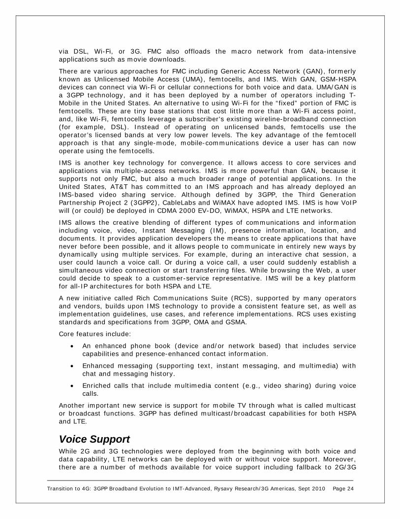
Voice Support While 2G and 3G technologies were deployed from the beginning with both voice and data capability, LTE networks can be deployed with or without voice support. Moreover, there are a number of methods available for voice support including fallback to 2G/3G

Transition to 4G: 3GPP Broadband Evolution to IMT-Advanced, Rysavy Research/3G Americas, Sept 2010 Page 25
and VoIP operation. These approaches are covered in more detail in the LTE section of the appendix.
Device Innovation Computing itself is becoming more mobile, and notebook computers and smartphones are now prevalent. In fact, all mobile phones are becoming “smart,” with some form of data capability, and leading notebook vendors are now offering computers with integrated 3G (e.g., HSPA) capabilities. Modems are available in multiple formats including USB devices, PC Cards, and Express cards.
Computer manufacturers are also delivering new form factors such as netbooks, tablet computers, mobile Internet devices (MID), and smartbooks. The movement to open networks also allows a greater number of companies to develop products that use wireless networks in both vertical-market and horizontal-market scenarios.
Cellular telephones are becoming more powerful and feature large color touch displays, graphics and video viewers, still cameras, movie cameras, music players, IM clients, e-mail clients, PoC, downloadable, executable content capabilities, and ever more powerful browsers. All of these capabilities consume data.
Meanwhile, smartphones are becoming extremely powerful computers with general-purpose operating systems and sophisticated application development environments. Smartphones, originally targeted for the high end of the market, are now available at much lower price points and thus affordable to a much larger market segment. Smartphones in the U.S. already account for some 25% of phones today, on track to reach 50% by 2011.28 The continued success of the BlackBerry along with the success of the iPhone and Android devices demonstrates the potential of this market.
From a radio perspective, today’s phones can support ever more bands and technologies. This makes world phones feasible. Increasingly, users expect their phones to work anywhere they go.
Network Interfaces for Applications Another important development related to service evolution is operators making interfaces available to external applications for information and control. Two widely deployed capabilities today include location queries and short message service (SMS). With location, mobile devices or external applications (e.g., applications operating on computers outside of the network) can query the location of a user, subject to privacy restrictions. This can significantly enhance many applications including navigation, supplying location of nearby destinations (e.g., restaurants, stores), location of friends for social networking, and worker dispatch. With SMS, external applications can send user-requested content such as flight updates.
Until now, the interfaces for such functions have either been proprietary, or specific to that function. There are now interfaces, however, that span multiple functions using a consistent set of programming methods. One set is the Parlay X Web Services, a set of functions specified through a joint project of the Parlay Group, the European Telecommunications Standards Institute (ETSI) and 3GPP. The Open Mobile Alliance (OMA) now manages the Parlay X specifications. Parlay X Web Services include support
28 Nielsen, “The Droid: Is this the Smartphone Consumers are Looking For?” November 11, 2009, http://blog.nielsen.com/nielsenwire/consumer/the-droid-is-this-the-smartphone-consumers-are-looking-for/.

Transition to 4G: 3GPP Broadband Evolution to IMT-Advanced, Rysavy Research/3G Americas, Sept 2010 Page 26
for location and SMS, as well as many other functions with which developers will be able to build innovative applications.
Table 3 summarizes the available Parlay X specifications.29 Operators are beginning to selectively deploy these functions. The advantage of this approach is that developers can build applications that are compatible with multiple operator networks.
Table 3: Parlay X Specifications
Part Title Functions
1 Common Definitions common across Parlay X specifications 2 Third Party Call Creates and manages calls 3 Call Notification Management of calls initiated by a subscriber 4 Short Messaging Send and receive of SMS including delivery receipts 5 Multimedia Messaging Send and receive of multimedia messages 6 Payment Pre-paid and post-paid payments and payment
reservations 7 Account Management Management of accounts of prepaid customers 8 Terminal Status Obtain status such as reachable, unreachable or busy 9 Terminal Location Obtain location of terminal 10 Call Handling Control by application for call handling of specific
numbers 11 Audio Call Control for media to be added/dropped during call 12 Multimedia Conference Create multimedia conferences including dynamic
management of participants 13 Address List
Management Manage subscriber groups
14 Presence Provide presence information 15 Message Broadcast Send messages to all users in specified area 16 Geocoding Obtain location address of subscriber 17 Application-driven QoS Control quality of service of end-user connection 18 Devices Capabilities
and Configuration Obtain device capability information and be able to push device configuration to device
19 Multimedia Streaming Control
Control multimedia streaming to device
20 Multimedia Multicast Session Management
Control multicast sessions, members, multimedia stream, and obtain channel presence information
A related project is GSM Association (GSMA) OneAPI, a project to also define network interfaces, but that prioritizes implementation based on expected market demand. OneAPI defines a simplified Web service for most functions that is essentially a subset of the related Parlay X Web service.30 It also defines a REST (Representational State Transfer) interface for most functions as an alternative to using the Web service. RESTful interfaces are simpler for developers to work with and experiment with than Web services.
Regardless of whether operators deploy with Parlay X or OneAPI, these are mainstream interfaces that will open wireless networks to thousands of Internet programmers who
29 See http://www.parlay.org/en/specifications/pxws.asp for actual specifications. 30 See http://oneapi.aepona.com/portal/tws_gsma/Resources for more information about OneAPI.

Transition to 4G: 3GPP Broadband Evolution to IMT-Advanced, Rysavy Research/3G Americas, Sept 2010 Page 27
will be able to build applications that leverage the latent information and capabilities of wireless networks.
Mobile Application Architectures Many applications used over wireless connections will be the same as those used over the Internet with desktop/laptop PCs. An increasing number of applications, however, will be developed specifically for mobile devices. This can be a challenge for developers, because there are a number of different mobile platforms now available including Android, Apple iPhone, LiMo, Palm Pre, RIM BlackBerry, Symbian, and Windows Mobile. Unlike the desktop market, the mobile device market has become fragmented. Each of the device platforms comes with its own application development environment, and developers must face a learning curve to become adept at programming for any specific platform. Some developers may be content targeting specific platforms. Others, however, may need their applications to operate across multiple platforms.
Fortunately, there are various developments that address the fragmentation challenge. These include:
Mobile Middleware. These are software infrastructures that consist of a client component that operates on the mobile device, and a server component that acts as a proxy for the client. Vendors provide tools with which developers can develop an application in a platform-neutral manner, and which then operates on multiple device types. Mobile middleware is mostly used for business applications.
Mobile Web 2.0. Mobile browsers are adopting many of the same sophisticated capabilities as desktop browsers. Combined with networks that have higher throughputs and lower latency, an increasing number of applications can be Web hosted, making the applications available from diverse platforms. Mobile Web 2.0 technologies include items such as Ajax, offline operation, video capabilities, fast JavaScript execution, and mashups (combining data from multiple Web sources). Cloud computing, enabled by Mobile Web 2.0, will play as important a role for mobile systems as for desktops.
Push Architectures. Many mobile applications are notification oriented, meaning users want to know when new information is available in applications like e-mail or social networking. “Pushing” small amounts of data on a regular basis to large numbers of users, or having devices poll on a regular basis, can strain impact network capacity. In response, 3GPP has specified supporting mechanisms such as Paging Channel (PCH) states and tools for enabling rapid transitions between active and inactive states.
Eventual Market Consolidation. Though the market is currently fragmented, there are certain platforms (e.g., Android, BlackBerry, iPhone) that represent relatively dominant market share. Increasingly, developers are choosing to develop for just a small number of these platforms using the development tools specific to that environment.
Broadband-Wireless Deployment Considerations Much of the debate in the wireless industry is on the merits of different radio technologies, yet other factors are equally important in determining the services and capabilities of a wireless network. These factors include the amount of spectrum available, backhaul, and network topology.

Transition to 4G: 3GPP Broadband Evolution to IMT-Advanced, Rysavy Research/3G Americas, Sept 2010 Page 28
Spectrum has always been a major consideration for deploying any wireless network, but it is particularly important when looking at high-performance broadband systems. HSPA and HSPA+ can deliver high throughput rates on the downlink and uplink with low latency in 5 MHz channels when deployed in single frequency (1/1) reuse. By this, we mean that every cell sector (typically three per cell) in every cell uses the same radio channel(s).
To achieve higher data rates requires wider radio channels, such as 10 or 20 MHz wide channels, in combination with emerging OFDMA radio technologies. Very few operators today, however, have access to this much spectrum. It was challenging enough for GSM operators to obtain UMTS spectrum. If delivering very high data rates is the objective, then the system must minimize interference. This result is best achieved by employing looser reuse, such as having every sector use only one-third of the available radio channels (1/3 reuse). The 10 MHz radio channel could now demand as much as 30 MHz of available spectrum.
Backhaul is another factor. As the throughput of the radio link increases, the circuits connecting the cell sites to the core network must be able to handle the increased load. With many cell sites today serviced by just a small number of T1/E1 circuits, each able to carry only 1.5/2.0 Mbps, operators are in the process of upgrading backhaul capacity to obtain the full benefit of next-generation wireless technologies. Approaches include emerging wireline technologies such as VDSL and optical Ethernet, as well as point-to-point microwave systems. An OFDMA system with 1.5 bps per hertz (Hz) of spectral efficiency in 10 MHz on three sectors has up to 45 Mbps average cell throughput. Additionally, any technology’s ability to reach its peak spectrum efficiency is somewhat contingent on the system’s ability to reach the instantaneous peak data rates allowed by that technology. For example, a system claiming spectrum efficiency of 1.5 bps/Hz (as described above) might rely on the ability to reach 100 Mbps instantaneously to achieve this level of spectrum efficiency. Any constraint on the transport system below 100 Mbps will restrict the range of achievable throughput and, in turn, impact the spectral efficiency of the system.
Finally, the overall network topology also plays an important role, especially with respect to latency. Low latency is critical to achieving very high data rates, because of the way it affects Transmission Control Protocol (TCP)/IP traffic. How traffic routes through the core network—how many hops and nodes it must pass through—can influence the overall performance of the network. One way to increase performance is by using flatter architectures, meaning a less hierarchical network with more direct routing from mobile device to end system. The core EPC network for 3GPP LTE emphasizes just such a flatter architecture.
In summary, it can be misleading to say that one wireless technology outperforms another without a full understanding of how that technology will be deployed in a complete system that also takes spectrum into account.
Data Offload As data loads increase, operators are seeking to offload some of the data traffic to other networks, particularly Wi-Fi networks. In the future, once they are widely deployed, offload onto femtocells will also play an important role.
The IEEE 802.11 family of technologies has experienced rapid growth, mainly in private deployments. The latest 802.11 standard, 802.11n, offers users throughputs in excess of 100 Mbps and improved range through use of MIMO. Complementary standards increase the attraction of the technology. 802.11e provides quality-of-service enabling VoIP and multimedia, 802.11i enables robust security, and 802.11r provides fast roaming, necessary for voice handover across access points.

Transition to 4G: 3GPP Broadband Evolution to IMT-Advanced, Rysavy Research/3G Americas, Sept 2010 Page 29
Leveraging this success, operators—including cellular operators—are offering hotspot service in public areas such as airports, fast-food restaurants, and hotels. For the most part, hotspots are complementary with cellular-data networks, because the hotspot can provide broadband services in extremely dense user areas and the cellular network can provide broadband services across much larger areas.
Wi-Fi has huge inherent capacity for two reasons. First, a large amount of spectrum (approximately 500 MHz) is available across 2.4 GHz and 5 bands. Second, the spectrum is used in small coverage areas, resulting in high frequency reuse. The result is much higher bps rates per square meter of coverage than with wide-area networks.
Various organizations are looking at integrating WLAN service with Global System for Mobile Communications (GSM)-HSPA data services. The GSM Association has developed recommendations for Subscriber Identity Module- (SIM-) based authentication of hotspots, and 3GPP has multiple initiatives that address WLAN integration into its networks, including 3GPP System to WLAN Interworking, UMA, IMS, and EPC.
Integration can either be loose or tight. Loose integration means data traffic routes directly to the Internet and minimizes traversal of the operator network. This is called local breakout. Tight integration means data traffic, or select portions, may traverse the operator core network. This is beneficial in situations where the operators offer value-added services (e.g., internal portals) that can only be accessed from within the core.
Essential to successful data offload is providing a good subscriber experience. This mandates measures such as automatically provisioning subscriber devices with the necessary Wi-Fi configuration options and automatically authenticating subscribers on supported public Wi-Fi networks.
Work in 3GPP Release 10 is defining some specific mechanisms for offloading traffic. One is called IP Flow and Seamless Offload (IFOM) used to carry select traffic over Wi-Fi instead of a femto connection. Another is called Selected IP Traffic Offload (SIPTO) used to offload the mobile core network by separating traffic out early.
Feature and Network Roadmap GSM operators first enhanced their networks to support data capability through the addition of General Packet Radio Service (GPRS) infrastructure with the ability to use existing cell sites, transceivers, and interconnection facilities. Since installing GPRS, GSM operators have largely upgraded data service to EDGE, and any new GSM network includes EDGE capability.
Operators have deployed UMTS-HSPA worldwide. Although UMTS involves a new radio-access network, several factors facilitate deployment. First, most UMTS cell sites can be collocated in GSM cell sites enabled by multi-radio cabinets that can accommodate GSM/EDGE, as well as UMTS equipment. Second, much of the GSM/GPRS core network can be used. This means that all core-network elements above the Serving GPRS Support Node (SGSN) and Mobile Switching Center (MSC)—the Gateway GPRS Support Node (GGSN), the Home Location Register (HLR), billing and subscriber administration systems, service platforms, and so forth—need, at most, a software upgrade to support 3G UMTS-HSPA. And while early 3G deployment used separate 2G/3G SGSNs and MSCs, all-new MSC and/or SGSN products are capable of supporting both GSM and UMTS-HSPA radio-access networks. Similarly, new HSPA equipment will be upgradeable to LTE through a software upgrade.
New features are being designed so that the same upgraded UMTS radio channel can support a mixture of terminals. In other words, a network supporting Release 5 features (for example, HSDPA) can support Release 99, Release 5, and Release 6 terminals (for

Transition to 4G: 3GPP Broadband Evolution to IMT-Advanced, Rysavy Research/3G Americas, Sept 2010 Page 30
example, HSUPA) operating in a Release 5 mode. This flexibility assures the maximum degree of forward- and backward-compatibility. Note also that most UMTS terminals today support GSM, thus facilitating use across large coverage areas and multiple networks.
Once deployed, operators can minimize the costs of managing GSM/EDGE and UMTS networks, because these networks share many of the same aspects including:
Packet-data architecture
Cell sites
Antenna systems
Backhaul circuits
Subscriber account management
Service platforms
Users largely don’t even need to know to what type of network they are connected, because their multimode GSM-HSPA (and eventually GSM-HSPA-LTE) devices can seamlessly hand off between networks.
The changes being planned for the core network are another aspect of evolution. Here, the intent is to reduce the number of nodes that packets must traverse. This will result in both reduced deployment costs and reduced latency. The key enabling technology is EPC, which is described in detail later in this paper.
The upgrade to LTE will be relatively straightforward, with new LTE infrastructure having the ability to reuse a significant amount of the UMTS-HSPA cell site and base station including using the same shelter, tower, antennas, power supply and climate control. Different vendors have different, so-called “zero-footprint” solutions allowing operators to use empty space to enable re-use of existing sites without the need for any new floor space.
An operator can add LTE capability simply by adding an LTE baseband card. New multi-standard radio units (HSPA and LTE), as well as LTE-only baseband cards, are mechanically compatible with older building practices, so that operators can use empty space in an old base station for LTE baseband cards, thus enabling re-use of existing sites without the need for any new floor space, as mentioned previously.
Base station equipment is available for many bands including the 1.7/2.1 GHz AWS band and the recently auctioned 700 MHz bands in the US. In 2010, operators and vendors began LTE deployment.
On the device side, multi-mode chipsets will enable devices to easily operate across UMTS and LTE networks. For example, one chipset vendor has announced a series of chips that support the following combination of technologies: UMTS, HSPA+ and LTE; EV-DO Rev B; and UMTS, HSPA+, EV-DO Rev B and LTE.31
One important and interesting aspect of technology deployment is that an advanced technology such as LTE enables operators to upgrade prior technologies, such as HSPA. Examples include:
31 http://www.qualcomm.com/press/releases/2008/080207_Qualcomm_to_Ship.html.

Transition to 4G: 3GPP Broadband Evolution to IMT-Advanced, Rysavy Research/3G Americas, Sept 2010 Page 31
VoIP for HSPA. Since LTE uses an IP core, once it is deployed, supporting voice on HSPA via VoIP will be a much simpler task as it can share the same core IP network as LTE.
Device processing power. Supporting the high throughput rates with LTE (e.g., 50 Mbps or higher) will provide sufficient processing in the device to also support very high HSPA rates (e.g., 30 Mbps or higher).
Table 4 shows the rollout of EDGE/HSPA/LTE features over time.
Table 4: Expected UMTS/LTE Feature and Capability Availability
Year Features
2010 Evolved EDGE capabilities available to significantly increase EDGE throughput rates and announced deployments.32
HSPA+ peak speeds further increased to peak rates of 42 Mbps based on Release 8.
LTE introduced for next-generation throughput performance using 2X2 MIMO.
Advanced core architectures available through EPC, primarily for LTE, but also for HSPA+, providing benefits such as integration of multiple network types and flatter architectures for better latency performance.
2011 LTE enhancements such as 4X2 MIMO and 4X4 MIMO available.
LTE-Advanced specifications completed.
HSPA+ with MIMO and dual-carrier available.
2012 and later
LTE-Advanced potentially deployed in initial stages.
HSPA+ with MIMO and quad-carrier available.
Most new services implemented in the packet domain.
Over time, the separate GSM/EDGE Radio Access Network (GERAN), UMTS Terrestrial Access Network (UTRAN), and core-infrastructure elements will undergo consolidation, thus lowering total network cost and improving integrated operation of the separate access networks. For actual users with multimode devices, the networks they access will be largely transparent. Today, nearly all UMTS phones and modems support GSM/EDGE.
Operators will deploy LTE in various configurations. Some will offer only data service on LTE. Others will offer data service on LTE in combination with voice over 2G or 3G. Yet others will provide both voice and data service on LTE. Individual operator configurations will also evolve over time.
Figure 9 presents the continuing advances in HSPA and LTE, plotted over time, showing an approximate doubling of throughput per year.
32 For example, March 31, 2010, announcement that Ericsson was deploying Evolved EDGE for Bharti Airtel in India.

Transition to 4G: 3GPP Broadband Evolution to IMT-Advanced, Rysavy Research/3G Americas, Sept 2010 Page 32
Figure 9: Peak Rates for Downlink and Uplink over Time33
Deployment Scenarios There are many different scenarios that operators will use to migrate from their current networks to future technologies such as LTE. Figure 10 presents various scenarios including operators who today are using CDMA2000, UMTS, GSM and Worldwide Interoperability for Microwave Access (WiMAX). For example, as shown in the first bar, a CMDA2000 operator in scenario A could defer LTE deployment to the longer term. In scenario B, in the medium term, the operator could deploy a combination of 1xRTT, EV-DO Rev A/B and LTE and, in the long term, could migrate EV-DO data traffic to LTE. In scenario C, a CDMA2000 operator with just 1xRTT could introduce LTE as a broadband service and, in the long term, could migrate 1xRTT users to LTE including voice service.
33 Source: A 3G Americas’ member company.
DL R’99-384k
HSDPA 1.8M
HSDPA 3.6M
HSDPA 7.2M
HSDPA 14.4M
MIMO 2x2 28M
MIMO/64QAM 42M
DL LTE (20MHz) 140MMIMO 2X2, 4X2
DL LTE (20MHz) 300MMIMO 4X4
kbps
Mbps
Mbps
100 kbps
1 Mbps
10 Mbps
100 Mbps
2004 2005 2006 2007 2008 2009 2010 2011 2012 2013
UL R’99 384k
HSUPA 1.5M
HSUPA 5.6M
HSUPA/16QAM 11M
UL LTE (10MHz) 25M16 QAM
UL LTE (10MHz) 50M64 QAM
• HSPA DL and UL peak throughputs expected to double every year on average
• Limitations not induced by the technology itself but time frames required to upgrade infrastructure and transport networks, obtain devices with corresponding capabilities and interoperability tests
Downlink Speeds
Uplink Speeds

Transition to 4G: 3GPP Broadband Evolution to IMT-Advanced, Rysavy Research/3G Americas, Sept 2010 Page 33
Figure 10: Different Deployment Scenarios for LTE34
3GPP and 3GPP2 both have specified detailed migration options for current 3G systems (UMTS-HSPA and EV-DO) to LTE. Due to economies of scale for infrastructure and devices, 3GPP operators are likely to have a competitive cost advantage over Third Generation Partnership Project 2 (3GPP2) operators.
One option for GSM operators that have not yet committed to UMTS, and do not have an immediate pressing need to do so, is to migrate directly from GSM/EDGE or Evolved EDGE to LTE with networks and devices supporting dual-mode GSM-EDGE/LTE operation.
34 Source: A 3G Americas’ member company.
GSMLTE
GSMLTE
GSM
GSMWCDMA
GSMGSMWCDMA
GSMWCDMA
LTE
GSMWCDMA
LTE
GSMWCDMA
LTE
3G1xCDMA to LTE LTE
3G1x3G1X
3G1xLTE
3G1xLTE
3G 1X
EV-DO RevAEV-DO RevA/B EV-DO RevA/B
Today Medium term Long term
Scenario A
Scenario B
W- CDMA to LTE
Scenario A
Scenario B
LTEWCDMA
GSM to LTE
WiMAXWiMAX.16e evol
some 16m features LTE
WiMAXWiMAX to LTE
3G1XEV-DO RevA
3G1XEV-DO RevA/B LTE
3G1xEV-DO RevA/B
Scenario c

Transition to 4G: 3GPP Broadband Evolution to IMT-Advanced, Rysavy Research/3G Americas, Sept 2010 Page 34
Competing Technologies Although GSM-HSPA networks are dominating global cellular-technology deployments, operators are deploying other wireless technologies to serve both wide and local areas. This section of the paper looks at the relationship between GSM/UMTS/LTE and some of these other technologies.
CDMA2000 CDMA2000, consisting principally of One Carrier Radio Transmission Technology (1xRTT) and One Carrier-Evolved, Data-Optimized (1xEV-DO) versions, is the other major cellular technology deployed in many parts of the world. 1xRTT is currently the most widely deployed CDMA2000 version. A number of operators have deployed or are deploying 1xEV-DO in which a radio carrier is dedicated to high-speed data functions. In July 2010, there were 114 EV-DO Rel. 0 networks and 95 EV-DO Rev. A networks deployed worldwide.35
Currently deployed network versions are based on either Rel. 0 or Rev. A radio-interface specifications. EV-DO Rev. A incorporates a more efficient uplink, which has spectral efficiency similar to that of HSUPA. Operators started to make EV-DO Rev. A commercially available in 2007.
EV-DO uses many of the same techniques for optimizing spectral efficiency as HSPA including higher order modulation, efficient scheduling, turbo-coding, and adaptive modulation and coding. For these reasons, it achieves spectral efficiency that is virtually the same as HSPA. The 1x technologies operate in the 1.25 MHz radio channels, compared to the 5 MHz channels UMTS uses, resulting in lower theoretical peak rates, although average throughputs for high level network loading are similar. Under low- to medium-load conditions, because of the lower peak achievable data rates, EV-DO or EV-DO Rev. A achieves a lower typical performance level than HSPA. Operators have quoted 400 to 700 kilobits per second (kbps) typical downlink throughput for EV-DO Rev. 036 and between 600 kbps and 1.4 Mbps for EV-DO Rev. A.37
One challenge for EV-DO operators is that they cannot dynamically allocate their entire spectral resources between voice and high-speed data functions. The EV-DO channel is not available for circuit-switched voice, and the 1xRTT channels offer only medium-speed data. In the current stage of the market, in which data only constitutes a small percentage of total network traffic, this is not a key issue. But as data usage expands, this limitation will cause suboptimal use of radio resources. Figure 11 illustrates this severe limitation.
35 Source: http://www.cdg.org, July 5, 2010. 36 Source: Verizon Broadband Access Web page, July 29, 2005. 37 Source: Sprint press release, January 30, 2007.

Transition to 4G: 3GPP Broadband Evolution to IMT-Advanced, Rysavy Research/3G Americas, Sept 2010 Page 35
Figure 11: Radio Resource Management 1xRTT/1xEV-DO versus UMTS-HSPA
Another limitation of using a separate channel for EV-DO data services is that it currently prevents users from engaging in simultaneous voice and high-speed data services, whereas this is possible with UMTS and HSPA. Many users enjoy having a tethered data connection from their laptop—by using Bluetooth, for example—and being able to initiate and receive phone calls while maintaining their data sessions.
EV-DO will eventually provide voice service using VoIP protocols through EV-DO Rev. A, which includes a higher speed uplink, QoS mechanisms in the network, and protocol optimizations to reduce packet overhead, as well as addressing problems such as jitter.
Even then, however, operators will face difficult choices: How many radio channels at each base station should be made available for 1xRTT to support legacy terminals versus how many radio channels should be allocated to EV-DO. In contrast, UMTS allows both circuit-switched and packet-switched traffic to occupy the same radio channel, where the amount of power each uses can be dynamically adjusted. This makes it simple to migrate users over time from circuit-switched voice to packet-switched voice.
3GPP2 has also defined EV-DO Rev. B, which can combine up to 15 1.25 MHz radio channels in 20 MHz—significantly boosting peak theoretical rates to 73.5 Mbps. More likely, an operator would combine three radio channels in 5 MHz. Such an approach by itself does not necessarily increase overall capacity, but it does offer users higher peak-data rates.
Beyond EV-DO Rev. B, 3GPP2 is working to finalize the specifications for EV-DO Rev C, sometimes referred to as EV-DO Advanced, this year. Expected enhancements include MIMO and 64 QAM in the downlink and 16 QAM in the uplink. No public details are yet available.
Thr
ee 1
.25
MH
z C
hann
els
One
5 M
Hz
Cha
nnel

Transition to 4G: 3GPP Broadband Evolution to IMT-Advanced, Rysavy Research/3G Americas, Sept 2010 Page 36
There are also a number of planned improvements for CDMA2000 1xRTT in a version referred to as 1x-Advanced that will significantly increase voice capacity, doubling it if all enhancements are implemented. CDMA operators are not only considering 1x-Advanced as a means to increase voice capacity, but as a means to free up spectrum to support more data services, such as deploying more EV-DO carriers or deploying LTE.
3GPP2 has defined technical means to integrate CDMA2000 networks with LTE along two available approaches:
1. Loose coupling. This involves little or no inter-system functionality, and resources are released in the source system prior to handover execution.
2. Tight coupling. The two systems intercommunicate with network-controlled make-before-break handovers. Tight coupling allows maintenance of data sessions with the same IP address. This will likely involve a more complex implementation than loose coupling.
CDMA2000 is clearly a viable and effective wireless technology and, to its credit, many of its innovations have been brought to market ahead of competing technologies.
WiMAX WiMAX has emerged as a potential alternative to cellular technology for wide-area wireless networks. Based on OFDMA and recently accepted by the ITU as an IMT-2000 (3G technology) under the name OFDMA TDD Wireless Metropolitan Area Network (WMAN), WiMAX is trying to challenge existing wireless technologies—promising greater capabilities and greater efficiencies than alternative approaches such as HSPA. But as WiMAX, particularly mobile WiMAX, has come closer to reality, vendors have continued to enhance HSPA and perceived WiMAX advantages are no longer apparent. Moreover, LTE networks are now beginning to be deployed.
Instead, WiMAX has gained the greatest traction in developing countries as an alternative to wireline deployment. In the United States, Clearwire, Sprint Nextel and others (Intel, Google, Comcast, Time Warner Cable, and Bright House Networks) have created a joint venture to deploy a nationwide WiMAX network. In July 2010, this network was available in 44 markets across the U.S. 38
The original specification, IEEE 802.16, was completed in 2001 and intended primarily for telecom backhaul applications in point-to-point, line-of-sight configurations using spectrum above 10 GHz. This original version of IEEE 802.16 uses a radio interface based on a single-carrier waveform.
The next major step in the evolution of IEEE 802.16 occurred in 2004 with the release of the IEEE 802.16-2004 standard. It added multiple radio interfaces, including one based on OFDM-256 and one based on OFDMA. IEEE 802.16-2004 also supports point-to-multipoint communications, sub-10 GHz operation, and non-line-of-sight communications. Like the original version of the standard, operation is fixed, meaning that subscriber stations are typically immobile. Potential applications include wireless Internet Service Provider (ISP) service and local telephony bypass (as an alternative to cable modem or DSL service). Vendors can design equipment for either licensed or unlicensed bands.
38 Source: Clearwire Press Release, “Clearwire Brings CLEAR 4G to Merced and Visalia, California,” July 1, 2010.

Transition to 4G: 3GPP Broadband Evolution to IMT-Advanced, Rysavy Research/3G Americas, Sept 2010 Page 37
IEEE 802.16e-2005 and now IEEE 802.16-2009 add mobility capabilities including support for radio operation while mobile, handovers across base stations, and handovers across operators. Unlike IEEE 802.16-2004, which operates in both licensed and unlicensed bands, IEEE 802.16e-2005 (referred to as mobile WiMAX) makes the most sense in licensed bands. Current WiMAX profiles emphasize TDD operation. Mobile WiMAX networks are not backward-compatible with IEEE 802.16-2004 networks.
Vendors deliver WiMAX Forum-certified equipment that conforms to subsets of IEEE 802.16e-2005 or IEEE 802.16-2009 as defined today. The IEEE itself does not define a certification process.
Current mobile WiMAX networks use 2X2 MIMO or 4X2 MIMO, TDD, and 10 MHz radio channels in a profile defined by the WiMAX Forum known as WiMAX Wave 2 or, more formally, as WiMAX System Profile 1.0. Beyond Release 1.0, the WiMAX Forum has defined a new profile called WiMAX Release 1.5. This profile includes various refinements intended to improve efficiency and performance and could be available for deployment in a similar timeframe as LTE.
Release 1.5 enhancements include Medium Access Control (MAC) overhead reductions for VoIP (persistent scheduling), handover optimizations, load balancing, location-based services support, Frequency Division Duplex (FDD) operation, 64 QAM in the uplink, downlink adaptive modulation and coding, closed-loop MIMO (FDD mode only), and uplink MIMO. There are no current Release 1.5 deployment plans.
A subsequent version, Mobile WiMAX 2.0, will be designed to address the performance requirements being developed in the ITU IMT-Advanced Project and will be standardized in a new IEEE standard, IEEE 802.16m. According to Sprint Nextel, IEEE 802.16m will be available in 2011.39 Deployment, however, depends on not just finalization of the IEEE specifications, but of associated WiMAX Forum profiles and associated certification programs.
WiMAX employs many of the same mechanisms as HSPA to maximize throughput and spectral efficiency, including high-order modulation, efficient coding, adaptive modulation and coding, and Hybrid Automatic Repeat Request (HARQ). The principal difference from HSPA is IEEE 802.16e-2005’s use of OFDMA. As discussed in the section “Technical Approaches (TDMA, CDMA, OFDMA)” above, OFDM provides a potential implementation advantage for wide radio channels (for example, 10 to 20 MHz). In 5 to 10 MHz radio channels, there is no evidence indicating that WiMAX will have any performance advantage compared with HSPA+.
It should be noted, however, that IEEE 802.16e-2005 contains some aspects that may limit its performance, particularly in scenarios in which a sector contains a large number of mobile users. The performance of the MAC layer is inefficient when scheduling large numbers of users, and some aspects—such as power control of the mobile station—are provided using MAC signaling messages rather than the fast power control used in WCDMA and other technologies. Thus, while WiMAX uses OFDMA, the performance will likely be somewhat less than HSPA due to increased overhead and other design issues.
Relative to LTE, WiMAX has the following technical disadvantages: 5 msec frames instead of 1 msec frames, Chase combining instead of incremental redundancy, coarser granularity for modulation and coding schemes and vertical coding instead of horizontal coding.40 One deployment consideration is that TDD requires network synchronization. It
39 Ali Tabassi, Sprint Nextel, Fierce Wireless Webcast, “WiMAX: Mobilizing the Internet”, March 5, 2008. 40 IEEE International Symposium on Personal, Indoor and Mobile Radio Communications: Anders Furuskär et al “The LTE Radio Interface – Key Characteristics and Performance,” 2008.

Transition to 4G: 3GPP Broadband Evolution to IMT-Advanced, Rysavy Research/3G Americas, Sept 2010 Page 38
is not possible for one cell site to be transmitting and an adjacent cell site to be receiving at the same time. Different operators in the same band must either coordinate their networks or have guard bands to ensure that they don’t interfere with each other.
Although IEEE 802.16e exploits significant radio innovations similar to HSPA+ and LTE, it faces challenges such as economies of scale and technology maturity. Very few operators today have access to spectrum for WiMAX that would permit them to provide widespread coverage.
In reference to economies of scale, GSM-HSPA subscribers number in the billions. Even over the next five years, the number of WiMAX subscribers is likely to be quite low. The Yankee Group projects 95 million subscribers by 2015.41
One specific area in which WiMAX has a technical disadvantage is cell size. In fact, 3G systems have a significant link budget advantage over mobile WiMAX because of soft-handoff diversity gain and an FDD duplexing advantage over TDD.42 Arthur D. Little reports that the radii of typical HSPA cells will be two to four times greater than typical mobile WiMAX cells for high-throughput operation.43 One vendor estimates that for the same power output, frequency, and capacity, mobile WiMAX requires 1.7 times more cell sites than HSPA.44 Given that many real world deployments of HSPA will occur at frequencies such as 850 MHz, and LTE at 700 MHz, WiMAX deployments at 2.5 GHz will be at a significant disadvantage.
With respect to spectral efficiency, WiMAX is comparable to HSPA+, as discussed in the section “Spectral Efficiency” that follows. As for data performance, HSPA+ in Release 8—with a peak rate of 42 Mbps—essentially matches mobile WiMAX in 10 MHz in TDD 3:1 DL:UL using 2X2 MIMO with a peak rate of 46 Mbps.
Some have cited intellectual property rights (IPR) as an area in which WiMAX has an advantage. There is little substantial, publicly available information, however, to support such claims. First, the large HSPA vendors have invested heavily in these technologies—hopefully giving them significant leverage with which to negotiate reasonable intellectual property rights rates with other vendors. Second, the mobile WiMAX industry is in its infancy, and there is considerable lack of clarity when it comes to how different companies will assert and resolve IPR issues.
Finally, wireless-data business models must also be considered. Today’s cellular networks can finance the deployment of data capabilities through a successful voice business. Building new networks for broadband wireless mandates substantial capacity per subscriber. Consumers who download 1 Gbyte of data each month represent a ten times greater load on the network than a 1,000-minute-a-month voice user. And if the future is in multimedia services such as movie downloads, it is important to recognize that downloading a single DVD-quality movie—even with advanced compression—consumes approximately 2 Gbytes. It is not clear how easily the available revenue-per-subscriber will be able to finance large-scale deployment of network capacity. Despite numerous
41 Source: Yankee Group, November 2009. http://4gtrends.com/?tag=mobile-wimax. 42 With a 2:1 TDD system, the reverse link only transmits one third of the time. To obtain the same cell edge data rates, the mobile system must transmit at 4.77 dB higher transmit power. 43 Source: "HSPA and mobile WiMAX for Mobile Broadband Wireless Access," 27 March 2007, Arthur D. Little Limited. 44 Source: Ericsson public white paper, “HSPA, the undisputed choice for mobile broadband, May 2007.”

Transition to 4G: 3GPP Broadband Evolution to IMT-Advanced, Rysavy Research/3G Americas, Sept 2010 Page 39
attempts, no terrestrial wireless-data-only network has ever succeeded as a business.45 Although there is discussion of providing voice services over WiMAX using VoIP, mobile-voice users demand ubiquitous coverage—including indoor coverage. Matching the cellular footprint with WiMAX will require national roaming arrangements, complemented by new dual-technology devices or significant operator investments.
Municipal Wi-Fi Systems Many cities are now deploying metro Wi-Fi systems that will provide Wi-Fi access in downtown areas. These systems are based on a mesh technology, wherein access points forward packets to nodes that have backhaul connections. Although some industry observers are predicting that these systems will have an adverse effect on 3G data services, metro Wi-Fi and 3G are more likely to be complementary in nature. Wi-Fi can generally provide better application performance over limited coverage areas, whereas 3G systems can provide access over much larger coverage areas.
Metro systems today are still quite immature and face the following challenges:
Many city projects have been discontinued due to the difficulty of providing a viable business model.
Today’s mesh systems are all proprietary. The IEEE is developing a mesh networking standard—IEEE 802.11s—which is in letter-ballot stage. Even then, it is not clear that vendors will adopt this standard for outdoor systems.
Coverage in most metro systems is designed to provide an outdoor signal. As such, the signal does not penetrate many buildings in the coverage area and repeaters are needed to propagate the signal indoors. Many early network deployments have experienced poorer coverage than initially expected, and the number of recommended access points per square mile has increased steadily.
Operation is in unlicensed bands in the 2.4 GHz radio channel. Given only three relatively non-overlapping radio channels at 2.4 GHz, interference between public and private systems is inevitable.
Although mesh architecture simplifies backhaul, there are still considerable expenses and networking considerations in backhauling a large number of outdoor access points.
Nevertheless, metro networks have attracted considerable interest, and some numbers of projects are still proceeding. Technical issues will likely be resolved over time, and as more devices support both 3G and Wi-Fi, users can look forward to multiple access options.
Comparison of Wireless Technologies This section of the paper compares the different wireless technologies looking at throughput, latency, spectral efficiency, and market position. Finally, the paper presents a table that summarizes the competitive position of the different technologies across multiple dimensions.
45 Source: Andy Seybold, January 18, 2006, commentary: “Will Data-Only Networks Ever Make Money?” http://www.outlook4mobility.com/commentary2006/jan1806.htm

Transition to 4G: 3GPP Broadband Evolution to IMT-Advanced, Rysavy Research/3G Americas, Sept 2010 Page 40
Data Throughput Data throughput is an important metric for quantifying network throughput performance. Unfortunately, the ways in which various organizations quote throughput statistics vary tremendously. This often results in misleading claims. The intent of this paper is to realistically represent the capabilities of these technologies.
One method of representing a technology’s throughput is what people call “peak throughput” or “peak network speed.” This refers to the fastest possible transmission speed over the radio link, and it is generally based on the highest order modulation available and the least amount of coding (error correction) overhead. Peak network speed is also usually quoted at layer 2 of the radio link. Because of protocol overhead, actual application throughput may be 10 to 20 percent lower (or more) than this layer-2 value. Even if the radio network can deliver this speed, other aspects of the network—such as the backhaul from base station to operator-infrastructure network—can often constrain throughput rates to levels below the radio-link rate.
Another method is to disclose throughputs actually measured in deployed networks with applications such as File Transfer Protocol (FTP) under favorable conditions, which assume light network loading (as low as one active data user in the cell sector) and favorable signal propagation. This number is useful because it demonstrates the high-end, actual capability of the technology. This paper refers to this rate as the “peak user rate.” Average rates, however, are lower than this peak rate and difficult to predict, because they depend on a multitude of operational and network factors. Except when the network is congested, however, the majority of users should experience throughput rates higher than one-half of the peak-achievable rate.
Some operators, primarily in the US, also quote typical throughput rates. These rates are based on throughput tests the operators have done across their operating networks and incorporate a higher level of network loading. Although the operators do not disclose the precise methodology they use to establish these figures, the values provide a good indication of what users can typically expect.
Table 5 presents the technologies in terms of peak network throughput rates, peak user-rates (under favorable conditions) and typical rates. It omits values that are not yet known such as those associated with future technologies.
The projected typical rates for HSPA+ and LTE show a wide range. This is because these technologies are designed to exploit favorable radio conditions to achieve very high throughput rates. Under poor radio conditions, however, throughput rates are lower.
Table 5: Throughput Performance of Different Wireless Technologies (Blue Indicates Theoretical Peak Rates, Green Typical)
Downlink Uplink Peak Network Speed
Peak and/or Typical User Rate
Peak Network Speed
Peak and/or Typical User Rate
EDGE (type 2 MS) 473.6 kbps 473.6 kbps
EDGE (type 1 MS) (Practical Terminal)
236.8 kbps 200 kbps peak
70 to 135 kbps typical
236.8 kbps 200 kbps peak
70 to 135 kbps typical
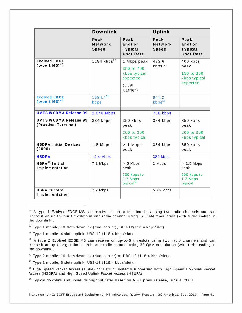
Transition to 4G: 3GPP Broadband Evolution to IMT-Advanced, Rysavy Research/3G Americas, Sept 2010 Page 41
Downlink Uplink Peak Network Speed
Peak and/or Typical User Rate
Peak Network Speed
Peak and/or Typical User Rate
Evolved EDGE (type 1 MS)46
1184 kbps47 1 Mbps peak
350 to 700 kbps typical expected
(Dual Carrier)
473.6 kbps48
400 kbps peak
150 to 300 kbps typical expected
Evolved EDGE (type 2 MS)49
1894.450 kbps
947.2 kbps51
UMTS WCDMA Release 99 2.048 Mbps 768 kbps
UMTS WCDMA Release 99 (Practical Terminal)
384 kbps 350 kbps peak
200 to 300 kbps typical
384 kbps 350 kbps peak
200 to 300 kbps typical
HSDPA Initial Devices (2006)
1.8 Mbps > 1 Mbps peak
384 kbps 350 kbps peak
HSDPA 14.4 Mbps 384 kbps
HSPA52 Initial Implementation
7.2 Mbps > 5 Mbps peak
700 kbps to 1.7 Mbps typical53
2 Mbps > 1.5 Mbps peak
500 kbps to 1.2 Mbps typical
HSPA Current Implementation
7.2 Mbps 5.76 Mbps
46 A type 1 Evolved EDGE MS can receive on up-to-ten timeslots using two radio channels and can transmit on up-to-four timeslots in one radio channel using 32 QAM modulation (with turbo coding in the downlink). 47 Type 1 mobile, 10 slots downlink (dual carrier), DBS-12(118.4 kbps/slot). 48 Type 1 mobile, 4 slots uplink, UBS-12 (118.4 kbps/slot). 49 A type 2 Evolved EDGE MS can receive on up-to-6 timeslots using two radio channels and can transmit on up-to-eight timeslots in one radio channel using 32 QAM modulation (with turbo coding in the downlink). 50 Type 2 mobile, 16 slots downlink (dual carrier) at DBS-12 (118.4 kbps/slot). 51 Type 2 mobile, 8 slots uplink, UBS-12 (118.4 kbps/slot). 52 High Speed Packet Access (HSPA) consists of systems supporting both High Speed Downlink Packet Access (HSDPA) and High Speed Uplink Packet Access (HSUPA). 53 Typical downlink and uplink throughput rates based on AT&T press release, June 4, 2008

Transition to 4G: 3GPP Broadband Evolution to IMT-Advanced, Rysavy Research/3G Americas, Sept 2010 Page 42
Downlink Uplink Peak Network Speed
Peak and/or Typical User Rate
Peak Network Speed
Peak and/or Typical User Rate
HSPA 14.4 Mbps 5.76 Mbps
HSPA+ (DL 64 QAM, UL 16 QAM, 2 X 5 MHz)
21.6 Mbps 1.9 Mbps to 8.8 Mbps54
13 Mbps peak55
11.5 Mbps 1 Mbps to 4 Mbps
HSPA+ (2X2 MIMO, DL 16 QAM, UL 16 QAM, 2 X 5 MHz)
28 Mbps 11.5 Mbps
HSPA+ (2X2 MIMO, DL 64 QAM, UL 16 QAM, 2 X 5 MHz)
42 Mbps 11.5 Mbps
HSPA+ (2X2 MIMO, DL 64 QAM, UL 16 QAM, Dual Carrier, 2 X 10 MHz)
84 Mbps
23 Mbps
HSPA+ (2X2 MIMO, DL 64 QAM, UL 16 QAM, Quad Carrier, 2 X 20 MHz)
168 Mbps 23 Mbps
LTE (2X2 MIMO, 2 X 10 MHz)
70 Mbps 5.9 to 21.5 Mbps56
35 Mbps57
LTE (4X4 MIMO, 2 X 20 MHz)
326 Mbps 86 Mbps
CDMA2000 1XRTT 153 kbps 130 kbps peak
153 kbps 130 kbps peak
CDMA2000 1XRTT 307 kbps 307 kbps
CDMA2000 EV-DO Rel 0 2.4 Mbps > 1 Mbps peak
153 kbps 150 kbps peak
CDMA2000 EV-DO Rev A 3.1 Mbps > 1.5 Mbps peak
1.8 Mbps > 1 Mbps peak
54 Source: 3G Americas member company analysis. Assumes Release 7 with 64 QAM and F-DPCH. Single user. 50% loading in neighboring cells. Higher rates expected with subsequent versions. 55 Source: Vodafone press release, “Vodafone Trials HSPA+ Mobile Broadband at Speeds of Up To 16Mbps,” January 15, 2009. 56 Source: 3G Americas’ member company analysis. Assumes single user with 50% load in other sectors. Verizon is quoting average user rates of 5-12 Mbps on the downlink and 2-5 Mbps on the uplink for their network. https://www.lte.vzw.com/AboutLTE/VerizonWirelessLTENetwork/tabid/6003/Default.aspx 57 Assumes 64 QAM. Otherwise 22 Mbps with 16 QAM.
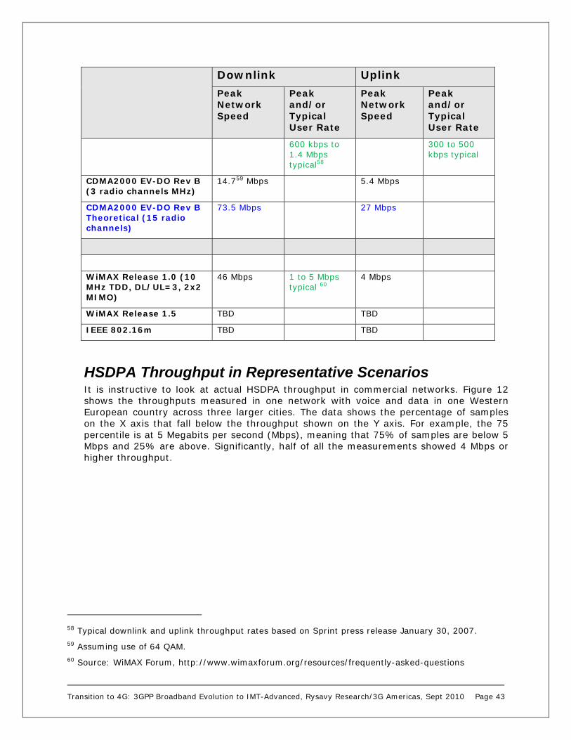
Transition to 4G: 3GPP Broadband Evolution to IMT-Advanced, Rysavy Research/3G Americas, Sept 2010 Page 43
Downlink Uplink Peak Network Speed
Peak and/or Typical User Rate
Peak Network Speed
Peak and/or Typical User Rate
600 kbps to 1.4 Mbps typical58
300 to 500 kbps typical
CDMA2000 EV-DO Rev B (3 radio channels MHz)
14.759 Mbps 5.4 Mbps
CDMA2000 EV-DO Rev B Theoretical (15 radio channels)
73.5 Mbps 27 Mbps
WiMAX Release 1.0 (10 MHz TDD, DL/UL=3, 2x2 MIMO)
46 Mbps 1 to 5 Mbps typical 60
4 Mbps
WiMAX Release 1.5 TBD TBD
IEEE 802.16m TBD TBD
HSDPA Throughput in Representative Scenarios It is instructive to look at actual HSDPA throughput in commercial networks. Figure 12 shows the throughputs measured in one network with voice and data in one Western European country across three larger cities. The data shows the percentage of samples on the X axis that fall below the throughput shown on the Y axis. For example, the 75 percentile is at 5 Megabits per second (Mbps), meaning that 75% of samples are below 5 Mbps and 25% are above. Significantly, half of all the measurements showed 4 Mbps or higher throughput.
58 Typical downlink and uplink throughput rates based on Sprint press release January 30, 2007. 59 Assuming use of 64 QAM. 60 Source: WiMAX Forum, http://www.wimaxforum.org/resources/frequently-asked-questions

Transition to 4G: 3GPP Broadband Evolution to IMT-Advanced, Rysavy Research/3G Americas, Sept 2010 Page 44
Figure 12: HSDPA Throughput Distribution in Deployed Networks61
In another network study, Figure 13 shows the downlink throughput performance of a 7.2 Mbps device (peak data rate capability). It results in a median throughput of 1.9 Mbps when mobile, 1.8 Mbps with poor coverage, and 3.8 Mbps with good coverage.
61 Source: 3G Americas’ member company contribution.
0.0
1.0
2.0
3.0
4.0
5.0
6.0
100% 95
%90
%85
%80
%75
%70
%65
%60
%55
%50
%45
%40
%35
%30
%25
%20
%15
%10
% 5% 0%
Th
rou
gh
pu
t [M
bp
s]

Transition to 4G: 3GPP Broadband Evolution to IMT-Advanced, Rysavy Research/3G Americas, Sept 2010 Page 45
Figure 13: HSDPA Performance of a 7.2 Mbps Device in a Commercial Network62
These rates are consistent with other vendor information for two deployed HSPA networks that supported 7.2 Mbps HSDPA. Testers measured average FTP downlink application throughput of 2.1 Mbps in the first network, and 1.9 Mbps in the second network.63
Release 99 and HSUPA Uplink Performance HSUPA dramatically increases uplink throughputs over 3GPP Release 99. Even Release 99 networks, however, have seen significant uplink increases. Many networks were initially deployed with a 64 kbps uplink rate. Later, this increased to 128 kbps. Later still, operators increased speeds to 384 kbps peak rates with peak user-achievable rates of 350 kbps.
The anticipated 1 Mbps achievable uplink throughput with HSUPA can be seen in the measured throughput of a commercial network as documented in Figure 14. The X axis shows throughput rate, the Y axis shows the cumulative distribution function, and the bars show the number of samples obtained for that throughput rate on a relative basis. The median bit rate is 1.0 Mbps.
62 Source: 3G Americas’ member company contribution. 63 Source: 3G Americas’ member company contribution.
Good Coverage
Median bitrate3.8 Mbps
Median bitrate1.8 Mbps
Bad Coverage
Median bitrate1.8 Mbps
Bad Coverage
-106 dBm
Mobile
Median bitrate1.9 Mbps
Mobile
Median bitrate1.9 Mbps

Transition to 4G: 3GPP Broadband Evolution to IMT-Advanced, Rysavy Research/3G Americas, Sept 2010 Page 46
Figure 14: Uplink Throughput in a Commercial Network64
These rates are consistent with other vendor information for a deployed HSPA network that supported 2.0 Mbps HSUPA65 uplink speed. Testers measured average FTP downlink application throughput of 1.2 Mbps.66
One operator has noted that in its networks, peak rates are often higher than the stated typical rates, because for a large percentage of cells and for a large percentage of time, cells are only lightly loaded.67
HSPA+ Throughput Performance measurements of HSPA+ networks show significant gains over HSPA. Figure 15 shows the cumulative distribution function of throughput values in a commercially-deployed HSPA+ network in an indoor-coverage scenario.
64 Source: 3G Americas’ member company contribution. 65 2 x spreading factor (2xSF2) code configuration. 66 Source: 3G Americas’ member company contribution. 67 Source: 3G Americas’ operator member observation for 2009 conditions.
0
70
140
210 280
350
420 490
560
630
700
770 840
910
980
105
0
112
0
119
0
126
0
133
0
140
0
0
10
20
30
40
50
60
70
80
90
100Mobile
Median bitrate1.0 Mbps
0
70
140
210 280
350
420 490
560
630
700
770 840
910
980
105
0
112
0
119
0
126
0
133
0
140
0
0
10
20
30
40
50
60
70
80
90
100
0
70
140
210 280
350
420 490
560
630
700
770 840
910
980
105
0
112
0
119
0
126
0
133
0
140
0
0
10
20
30
40
50
60
70
80
90
100Mobile
Median bitrate1.0 Mbps

Transition to 4G: 3GPP Broadband Evolution to IMT-Advanced, Rysavy Research/3G Americas, Sept 2010 Page 47
Figure 15: HSPA+ Performance Measurements Commercial Network (2 X 5MHz)68
The figure shows a reasonably typical indoor scenario in a macro-cell deployment. Under better radio conditions, HSPA+ will achieve higher performance results.
LTE Throughput Figure 16 shows the result of a drive test in a commercial LTE network with a 10 MHz carrier demonstrating 20 to 50 Mbps throughput rates across much of the coverage area.
68 Source: 3G Americas’ member company contribution.
0 2000 4000 6000 8000 10000 120000
20
40
60
80
100
cdf
, %
7.2 21 28
Indoor coverage RSCP: -98 dBm
Median MIMO: 8.2 Mbps 64QAM: 7.2 MbpsHSPA7.2: 6.0 Mbps
Throughput (kbps)

Transition to 4G: 3GPP Broadband Evolution to IMT-Advanced, Rysavy Research/3G Americas, Sept 2010 Page 48
Figure 16: Drive Test of Commercial European LTE Network (2 X 10MHz)69
Figure 17 provides additional insight into LTE downlink throughput, showing layer 1 throughput simulated at 10 MHz bandwidth using the Extended Vehicular A 3 km/hour channel model. The figure shows the increased performance obtained with the addition of different orders of MIMO.
69 Source: 3G Americas’ member company contribution.
Mbps

Transition to 4G: 3GPP Broadband Evolution to IMT-Advanced, Rysavy Research/3G Americas, Sept 2010 Page 49
Figure 17: LTE Throughput in Various Modes70
For typical and average throughputs, it is reasonable to expect an order of magnitude higher performance than HSPA, which one can anticipate from radio channels that are four times wider (20 MHz vs. 5 MHz), and at least a doubling of spectral efficiency.
Actual throughput rates that users will experience will be lower than the peak rates and will depend on a variety of factors including:
1. RF Conditions and User Speed. Peak rates depend on optimal conditions. Under suboptimal conditions, such as being at the edge of the cell or if the user is moving at high speed, throughput rates will be lower.
2. Network Loading. Like all wireless systems, the throughput rates will go down as more users simultaneously use the network. This is largely a linear degradation.
3. Protocol Overhead. Peak rates are generally stated for the physical layer. Due to overhead at other layers, actual data payload throughput rates may be lower by an approximate 5% to 20% amount. The precise amount depends on the size of packets. Larger packets (e.g., file downloads) result in a lower overhead ratio.
Figure 18 shows how throughput rates can vary by number of active users and radio conditions. The higher curves are for better radio conditions.
70 Source: “Initial Field Performance Measurements of LTE,” Jonas Karlsson, Mathias Riback, Ericsson Review No. 3 2008, http://www.ericsson.com/ericsson/corpinfo/publications/review/2008_03/files/LTE.pdf.

Transition to 4G: 3GPP Broadband Evolution to IMT-Advanced, Rysavy Research/3G Americas, Sept 2010 Page 50
Figure 18: LTE Actual Throughput Rates Based on Conditions71
Verizon Wireless has stated that it expects its LTE network to deliver 8 to 12 Mbps of throughput.72
Latency Just as important as throughput is network latency, defined as the round-trip time it takes data to traverse the network. Each successive data technology from GPRS forward reduces latency, with HSDPA networks having latency as low as 70 milliseconds (msec). HSUPA brings latency down even further, as will 3GPP LTE. Ongoing improvements in each technology mean that all of these values will go down as vendors and operators fine-tune their systems. Figure 19 shows the latency of different 3GPP technologies.
71 Source: LTE/SAE Trial Initiative, “Latest Results from the LSTI, Feb 2009,” www.lstiforum.org. 72 Source: http://gigaom.com/2009/05/15/verizons-lte-plans-get-real/.

Transition to 4G: 3GPP Broadband Evolution to IMT-Advanced, Rysavy Research/3G Americas, Sept 2010 Page 51
Figure 19: Latency of Different Technologies73
Except for LTE, values shown in Figure 19 reflect measurements of commercially deployed technologies. Some vendors have reported significantly lower values in networks using their equipment, such as 150 msec for EDGE, 70 msec for HSDPA, and 50 msec for HSPA. With further refinements and the use of 2 msec Transmission Time Interval (TTI) in the HSPA uplink, 25 msec roundtrip is a realistic goal. LTE will reduce latency even further, to as low as 10 msec in the radio-access network.
Spectral Efficiency To better understand the reasons for deploying the different data technologies and to better predict the evolution of capability, it is useful to examine spectral efficiency. The evolution of data services is characterized by an increasing number of users with ever-higher bandwidth demands. As the wireless-data market grows, deploying wireless technologies with high spectral efficiency will be of paramount importance. Keeping all other things equal such as frequency band, amount of spectrum, and cell site spacing, an increase in spectral efficiency translates to a proportional increase in the number of users supported at the same load per user—or, for the same number of users, an increase in throughput available to each user. Delivering broadband services to large numbers of users can best be achieved with high spectral-efficiency systems, especially because the only other alternatives are using more spectrum or deploying more cell sites.
73 Source: 3G Americas' member companies. Measured between subscriber unit and Gi interface, immediately external to wireless network. Does not include Internet latency. Note that there is some variation in latency based on network configuration and operating conditions.
100
700
600
500
400
300
200
GPRSRel’97
EDGERel’99
EDGERel’4
WCDMARel’99
EvolvedEDGE
Mill
ise
con
ds
LTEHSPAHSDPA

Transition to 4G: 3GPP Broadband Evolution to IMT-Advanced, Rysavy Research/3G Americas, Sept 2010 Page 52
Increased spectral efficiency, however, comes at a price. It generally implies greater complexity for both user and base station equipment. Complexity can arise from the increased number of calculations performed to process signals or from additional radio components. Hence, operators and vendors must balance market needs against network and equipment costs. One core aspect of evolving wireless technology is managing the complexity associated with achieving higher spectral efficiency. The reason technologies such as OFDMA are attractive is that they allow higher spectral efficiency with lower overall complexity; thus their use in technologies such as LTE and WiMAX.
The roadmap for the EDGE/HSPA/LTE family of technologies provides a wide portfolio of options to increase spectral efficiency. The exact timing for deploying these options is difficult to predict, because much will depend on the growth of the wireless data market and what types of applications become popular.
When determining the best area on which to focus future technology enhancements, it is interesting to note that HSDPA, 1xEV-DO, and IEEE 802.16e-2005 all have highly optimized links—that is, physical layers. In fact, as shown in Figure 20, the link layer performance of these technologies is approaching the theoretical limits as defined by the Shannon bound. (The Shannon bound is a theoretical limit to the information transfer rate [per unit bandwidth] that can be supported by any communications link. The bound is a function of the Signal to Noise Ratio [SNR] of the communications link.) Figure 20 also shows that HSDPA, 1xEV-DO, and IEEE 802.16e-2005 are all within 2 to 3 decibels (dB) of the Shannon bound, indicating that there is not much room for improvement from a link-layer perspective. Note that differences do exist in the design of the MAC layer (layer 2), and this may result in lower than expected performance in some cases as described previously.

Transition to 4G: 3GPP Broadband Evolution to IMT-Advanced, Rysavy Research/3G Americas, Sept 2010 Page 53
Figure 20: Performance Relative to Theoretical Limits for HSDPA, EV-DO, and IEEE 802.16e-200574
The curves in Figure 20 are for an Additive White Gaussian Noise Channel (AWGN). If the channel is slowly varying and the frame interval is significantly shorter than the coherence time, the effects of fading can be compensated for by practical channel estimation algorithms—thus justifying the AWGN assumption. For instance, at 3 km per hour, and fading at 2 GHz, the Doppler spread is about 5.5 Hz. The coherence time of the channel is thus 1 second (sec)/5.5 or 180 msec. Frames are well within the coherence time of the channel, because they are typically 20 msec or less. As such, the channel appears “constant” over a frame and the Shannon bound applies. Furthermore, significantly more of the traffic in a cellular system is at slow speeds (for example, 3 km/hr or less) rather than at higher speeds. The Shannon bound is consequently also relevant for a realistic deployment environment.
As the speed of the mobile station increases and the channel estimation becomes less accurate, additional margin is needed. This additional margin, however, would impact the different standards fairly equally.
The Shannon bound only applies to a single link; techniques such as MIMO using multiple links would have a higher bound. It does indicate, however, that link layer performance is reaching theoretical limits. As such, the focus of future technology enhancements should be on improving system performance aspects that maximize the experienced Signal to Noise Ratios (SNRs) in the system rather than on investigating new air interfaces that attempt to improve the link layer performance.
74 Source: A 3G Americas’ member company.
-15 -10 -5 0 5 10 15 200
1
2
3
4
5
6
Required SNR (dB)
Ach
ieva
ble
Effic
ienc
y (b
ps/
Hz)
Shannon boundShannon bound with 3dB margin
EV-DOIEEE 802.16e-2005
HSDPA
Transition to 4G: 3GPP Broadband Evolution to IMT-Advanced, Rysavy Research/3G Americas, Sept 2010 Page 54
Examples of technologies that improve SNR in the system are those that minimize interference through intelligent antennas or interference coordination/cancellation between sectors and cells. Note that MIMO techniques using spatial multiplexing to potentially increase the overall information transfer rate by a factor proportional to the number of transmit or receive antennas do not violate the Shannon bound, because the per-antenna transfer rate (that is, the per-communications link transfer rate) is still limited by the Shannon bound.
Figure 21 compares the spectral efficiency of different wireless technologies based on a consensus view of 3G Americas’ contributors to this paper. It shows the continuing evolution of the capabilities of all the technologies discussed. The values shown are reasonably representative of real-world conditions. Most simulation results produce values under idealized conditions; as such, some of the values shown are lower (for all technologies) than the values indicated in other papers and publications. For instance, 3GPP studies indicate higher HSDPA and LTE spectral efficiencies than those shown below. Nevertheless, there are practical considerations in implementing technologies that can prevent actual deployments from reaching calculated values. Consequently, initial versions of technology may operate at lower levels, but then improve over time as designs are optimized. Therefore, readers should interpret the values shown as achievable, but not as the actual values that might be measured in any specific deployed network.

Transition to 4G: 3GPP Broadband Evolution to IMT-Advanced, Rysavy Research/3G Americas, Sept 2010 Page 55
Figure 21: Comparison of Downlink Spectral Efficiency75
The values shown in Figure 21 are not all the possible combinations of available features. Rather, they are representative milestones in ongoing improvements in spectral efficiency. For instance, there are terminals that employ mobile-receive diversity but not equalization.
The figure does not include EDGE, but EDGE itself is spectrally efficient at 0.3 bits per second (bps)/Hertz (Hz)/sector. Relative to WCDMA Release 99, HSDPA increases capacity by almost a factor of three. Type 3 receivers that include Minimum Mean Square Error (MMSE) equalization and Mobile Receive Diversity (MRxD) will effectively double HSDPA spectral efficiency. HSPA+ in Release 7 includes 2X2 MIMO, which further increases spectral efficiency by about 20 percent and exceeds WiMAX Release 1.0 spectral efficiency. Methods like successive interference cancellation (SIC) and 64 QAM allow gains in spectral efficiency as high as 1.3 bps/Hz/sector, which is close to LTE performance in 5+5 MHz channel bandwidth. Terminals with SIC can also be used with Release 7 systems. Dual-carrier HSPA will offer a further modest gain in spectral efficiency from cross-carrier scheduling with possible gains of about 10%.76 With Release
75 Joint analysis by 3G Americas’ members. 5+5 MHz for UMTS-HSPA/LTE and CDMA2000, and 10 MHz DL/UL=29:18 TDD for WiMAX. Mix of mobile and stationary users. 76 Source: 3G Americas’ member analysis. Vendor estimates for spectral-efficiency gains from dual-carrier operation range from 5% to 20%. Lower spectral efficiency gains are due to full-buffer traffic assumptions. In more realistic operating scenarios, gains will be significantly higher.
0.1
0.70.60.50.40.30.2
UMTS/HSPA
Spe
ctra
l Eff
icie
ncy
(bps
/Hz/
sect
or)
0.80.9
UMTS R’99
HSDPA EV-DO Rev 0
Rev BCross-Carrier Scheduling
Rev A,MRxD,Equalizer
Rel 1.02X2 MIMO
CDMA2000 WiMAX
1.41.31.21.11.0
LTE2X2 MIMO
HSPA+ 2X2 MIMO
HSPA+SIC, 64 QAM
HSDPAMRxD,Equalizer
1.5
2.12.01.91.81.71.6
2.22.3
2.52.4
Futureimprovements
LTE4X2 MIMO
Rel 1.52X2 MIMO
Rel 1.54X2 MIMO
FutureimprovementsFuture
improvements
LTE
Futureimprovements
LTE4X4 MIMOSIC

Transition to 4G: 3GPP Broadband Evolution to IMT-Advanced, Rysavy Research/3G Americas, Sept 2010 Page 56
8, operators can deploy either MIMO or dual-carrier operation. With Release 9, dual-carrier operation can be combined with MIMO.
With respect to actual deployment, some enhancements, such as 64 QAM, will be simpler for some operators to deploy than other enhancements such as 2X2 MIMO. The former can be done as a software upgrade, whereas the latter requires additional hardware at the base station. Thus, the figure does not necessarily show the actual progression of technologies that operators will deploy to increase spectral efficiency.
Beyond HSPA, 3GPP LTE will also result in further spectral efficiency gains, initially with 2X2 MIMO, and then optionally with SIC, 4X2 MIMO and 4X4 MIMO. The gain for 4X2 MIMO will be 20% more than LTE with 2X2 MIMO; the gain for 4X4 MIMO in combination with successive interference cancellation will be 60% more than 2X2 MIMO. This assumes a simplified switched-beam approach defined in Release 8. Higher gains are possible with more advanced adaptive antenna and beam-forming algorithms, but are based on proprietary implementations and, thus, the actual gains will depend on implementation. The same is true for WiMAX. Downloadable codebooks in Release 9 LTE provide one avenue for such additional gains. Multi-user MIMO can provide higher spectral-efficiency gains than single-user MIMO and is being considered carefully in Release 10 standardization efforts.
LTE is even more spectrally efficient with wider channels, such as 10 and 20 MHz, although most of the gain is realized at 10 MHz. LTE TDD has spectral efficiency that is within 1 or 2% of LTE FDD.
Similar gains to those for HSPA and LTE are available for CDMA2000. CDMA2000 spectral efficiency values assume 7 carriers deployed in 10 MHz. The EV-DO Rev 0 value assumes single receive-antenna devices. As with HSPA, spectral efficiency for EV-DO increases with a higher population of devices with mobile receive diversity. These gains are assumed in the Rev A spectral-efficiency value of .9 bps/Hz.
Mobile WiMAX also experiences gains in spectral efficiency as various optimizations, like MRxD and MIMO, are applied. WiMAX Release 1.0 includes 2X2 MIMO. Enhancements to WiMAX will come with Release 1.5, as well as other future enhancements.
The main reason that HSPA+ with MIMO is shown as more spectrally efficient than WiMAX Release 1.0 with MIMO is because HSPA MIMO supports closed-loop operation with precode weighting and multi-codeword MIMO, which enables the use of SIC receivers. Other reasons are that HSPA supports incremental-redundancy HARQ, while WiMAX supports only Chase combining HARQ, and that WiMAX has larger control overhead in the downlink than HSPA, because the uplink in WiMAX is fully scheduled. OFDMA technology requires scheduling to avoid two mobile devices transmitting on the same tones simultaneously. An uplink MAP zone in the downlink channel does this scheduling.
LTE has higher spectral efficiency than WiMAX Release 1.0 for a number of reasons 77:
Closed-loop operation with precoded weighting.
Multi-codeword MIMO, which enables the use of SIC receivers.
Lower Channel Quality Indicator delay through use of 1 msec frames instead of 5 msec frames.
Greater control channel efficiency. 77 IEEE International Symposium on Personal, Indoor and Mobile Radio Communications: Anders Furuskär et al “The LTE Radio Interface – Key Characteristics and Performance,” 2008.

Transition to 4G: 3GPP Broadband Evolution to IMT-Advanced, Rysavy Research/3G Americas, Sept 2010 Page 57
Incremental redundancy in error correction.
Finer granularity of modulation and coding schemes.
WiMAX Release 1.5 addresses some of these items and thus will have increased spectral efficiency. Expected features include reduced MAC overhead, adaptive modulation and coding, and other physical-layer enhancements.
One available improvement for LTE spectral efficiency not shown in the figure is successive interference cancellation. This will result in a gain of 5% in a low-mobility environment and a gain of 10 to 15% in environments such as picocells in which there is cell isolation.
The following table summarizes the most important features of LTE and WiMAX technology that impact spectral efficiency.
Table 6: LTE and WiMAX Features
Feature LTE WiMAX Release 1.0
WiMAX Release 1.5
Impact
Multiple Access
OFDM in downlink, Discrete Fourier Transform (DFT)-spread OFDM in uplink
OFDM in downlink and uplink
OFDM in downlink and uplink
DFT-spread OFDM reduces the peak-to-average power ratio and reduces terminal complexity, requires one-tap equalizer in base station receiver.
Uplink Power Control
Fractional path-loss compensation
Full path-loss compensation
Full path-loss compensation
Fractional path-loss compensation enables flexible tradeoff between average and cell-edge data rates.
Scheduling Channel dependent in time and frequency domains
Channel dependent in time domain
Channel dependent in time and frequency domains
Access to the frequency domain yields larger scheduling gains.
MIMO Scheme Multi-codeword (horizontal), closed loop with pre-coding
Single codeword (vertical)
Single codeword (vertical), with rank-adaptive MIMO (TDD) and with closed-loop pre-coding (FDD)
Horizontal encoding enables per-stream link adaptation and successive interference cancellation receivers.
Modulation and Coding Scheme Granularity
Fine granularity (1-2 dB apart)
Coarse granularity (2-3 dB apart)
Coarse granularity (2-3 db apart)
Finer granularity enables better link adaptation precision.
Hybrid Automatic Repeat Request (ARQ)
Incremental redundancy
Chase combining Chase combining Incremental redundancy is more efficient (lower SNR required for given error rate).
Frame Duration
1 msec subframes
5 msec subframes 5 msec subframes Shorter subframes yield lower user plane delay and reduced channel quality feedback delays.
Overhead / Control Channel Efficiency
Relatively low overhead
Relatively high overhead
Relatively high overhead apart from reduction in pilots
Lower overhead improves performance.
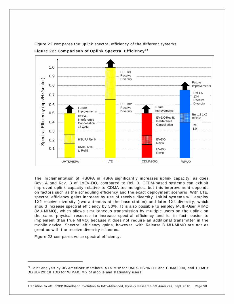
Transition to 4G: 3GPP Broadband Evolution to IMT-Advanced, Rysavy Research/3G Americas, Sept 2010 Page 58
Figure 22 compares the uplink spectral efficiency of the different systems.
Figure 22: Comparison of Uplink Spectral Efficiency78
The implementation of HSUPA in HSPA significantly increases uplink capacity, as does Rev. A and Rev. B of 1xEV-DO, compared to Rel. 0. OFDM-based systems can exhibit improved uplink capacity relative to CDMA technologies, but this improvement depends on factors such as the scheduling efficiency and the exact deployment scenario. With LTE, spectral efficiency gains increase by use of receive diversity. Initial systems will employ 1X2 receive diversity (two antennas at the base station) and later 1X4 diversity, which should increase spectral efficiency by 50%. It is also possible to employ Multi-User MIMO (MU-MIMO), which allows simultaneous transmission by multiple users on the uplink on the same physical resource to increase spectral efficiency and is, in fact, easier to implement than true MIMO, because it does not require an additional transmitter in the mobile device. Spectral efficiency gains, however, with Release 8 MU-MIMO are not as great as with the receive diversity schemes.
Figure 23 compares voice spectral efficiency.
78 Joint analysis by 3G Americas’ members. 5+5 MHz for UMTS-HSPA/LTE and CDMA2000, and 10 MHz DL/UL=29:18 TDD for WiMAX. Mix of mobile and stationary users.
0.1
0.7
0.6
0.5
0.4
0.3
0.2
Spe
ctra
l Eff
icie
ncy
(bps
/Hz/
sect
or)
0.8
0.9
UMTS R’99to Rel 5
HSUPA Rel 6
LTE 1X2ReceiveDiversity
EV-DO Rev 0
EV-DO Rev B,InterferenceCancellation
EV-DO Rev A
HSPA+InterferenceCancellation,16 QAM
LTE 1x4ReceiveDiversity
FutureImprovements
FutureImprovements
1.0
UMTS/HSPA CDMA2000 WiMAXLTE
Rel 1.0
FutureImprovements
Rel 1.5 1X2Rx Div
Rel 1.5 1X4ReceiveDiversity

Transition to 4G: 3GPP Broadband Evolution to IMT-Advanced, Rysavy Research/3G Americas, Sept 2010 Page 59
Figure 23: Comparison of Voice Spectral Efficiency79
Figure 23 shows UMTS Release 99 with AMR 12.2 kbps, 7.95 kbps, and 5.9 kbps vocoders. The AMR 12.2 kbps vocoder provides superior voice quality in good (e.g., static, indoors) channel conditions. UMTS has dynamic adaptation between vocoder rates, enabling enhanced voice quality compared to EVRC at the expense of capacity in situations that are not capacity limited. With the addition of mobile receive diversity, UMTS circuit-switched voice capacity could reach 240 Erlangs in 10 MHz.
Opportunities will arise to improve voice capacity using VoIP over HSPA channels. VoIP Erlangs in this paper are defined as the average number of concurrent VoIP users that can be supported over a defined period of time (often 1 hour) assuming a Poisson arrival process and meeting a specified outage criteria (often less than 2% of the users exhibiting greater than 1% frame-error rate). Depending on the specific enhancements implemented, voice capacity could double over existing circuit-switched systems. It should be noted, however, that the gains are not related specifically to the use of VoIP; rather, gains relate to advances in radio techniques applied to the data channels. Many of these same advances may also be applied to current circuit-switched modes. Other benefits of VoIP, however, are driving the migration to packet voice. Among these benefits is a consolidated IP core network for operators and sophisticated multimedia applications for users.
LTE achieves very high voice spectral efficiency because of better uplink performance since there is no in-cell interference. The figure shows LTE VoIP spectral efficiency using AMR at 12.2 kbps, 7.95 kbps and 5.9 kbps.
79 Source: Joint analysis by 3G Americas’ members. 10 + 10 MHz for UMTS-HSPA/LTE and CDMA2000, and 20 MHz DL/UL=29:18 TDD for WiMAX. Mix of mobile and stationary users.
50
350
300
250
200
150
100
Erla
ngs,
10+
10 M
Hz
UMTSAMR 7.95 kbps
HSPA VOIP, InterferenceCancellationAMR 5.9 kbps
1xRTTEVRC 8 kbps
VOIP, IC,EVRC-B 6 kbps
Rel 1.5EVRC-B 6kbpsUMTS
AMR 5.9 kbps
500
450
400
LTE AMR 5.9 kbps
UMTS MRxD AMR 5.9 kbps
FutureImprovements
FutureImprovements
FutureImprovements
Rel 1.0EVRC 8 kbps
LTE AMR 7.95 kbps
UMTSAMR 12.2 kbps
UMTS/HSPA CDMA2000 WiMAXLTE
FutureImprovements
QLICEVRC-B 6 kbps
LTE VoIPAMR 12.2 kbps
1xRTT QLIC, EVRC-B 6 kbps
EV-DO Rev A VoIP, IC, EVRC-B 6 kbps
Transition to 4G: 3GPP Broadband Evolution to IMT-Advanced, Rysavy Research/3G Americas, Sept 2010 Page 60
1xRTT reaches voice spectral efficiency of 280 Erlangs in 10 MHz with the use of Quasi-Linear Interference Cancellation (QLIC), EVRC-B at 6 kbps, and the use of seven radio channels. With six channels, voice capacity is 240 Erlangs.
There are a number of planned improvements for CDMA2000 in a project called 1x-Advanced that will result in significantly increased voice capacity. With all enhancements implemented, 1x-Advanced could double 1xRTT voice efficiency.
EV-DO technologies could possibly exhibit a slightly higher spectral efficiency for VoIP than HSPA technologies (although not for packet data in general), as they operate purely in the packet domain and do not have circuit-switched control overhead.80 Until VoIP over EV-DO becomes available, HSPA will have the significant advantage, however, of being able to support simultaneous circuit-switched and packet-switched users on the same radio channel. If adjacent carriers are available, seven CDMA2000 carriers can be deployed in 10 MHz of spectrum, providing an additional gain of 12%.
With respect to codecs, in VoIP systems such as LTE and WiMAX, a variety of codecs can be used. The figures show performance assuming specific codecs at representative bit rates. For codecs such as EVRC (Enhanced Variable Rate Codec), the bit rate shown is an average value.
WiMAX voice spectral efficiency is shown at 180 Erlangs for Release 1.0 and 210 Erlangs for Release 1.5. A spectral efficiency gain of 50% is available by changing the Downlink:Uplink (DL:UL) ratio from 29:18 to 23:24, since now 18 data symbols per frame are allocated for the UL compared to 12. A further gain of 15% is available through the use of persistent scheduling and changing the DL:UL from 23:24 to 20:27.81 Changing this ratio, however, may not be practical if the same carrier frequency must support both voice and data. Alternatively, voice and data may be placed on different carriers using different TDD ratios.
Cost, Volume, and Market Comparison So far, this paper has compared wireless technologies on the basis of technical capability and demonstrated that many of the different options have similar technical attributes. This is for the simple reason that they employ many of the same approaches.
There is a point of comparison, however, in which the differences between the technologies diverge tremendously; namely, the difference in volume involved including subscribers and the amount of infrastructure required. This difference should translate to dramatically reduced costs for the highest volume solutions, specifically GSM-HSPA. Based on projections and numbers already presented in this paper, 3G subscribers on UMTS networks will number in the many hundreds of millions by the end of this decade, whereas subscribers to emerging wireless technologies, such as WiMAX, will number in the tens of millions. See Figure 24 for details.
80 Transmit Power Control (TPC) bits on the uplink Dedicated Physical Control Channel (DPCCH) in UMTS R’99. See also IEEE Journal on Selected Areas in Communication, Vol 24, No.1, Qi Bi, “An Analysis of VoIP Service Using 1 EV-DO Revision A System,” January, 2006. 81 Source: IEEE Communications Magazine, Mo-Han Fong and Robert Novak, Nortel Networks, Sean McBeath, Huawei Technologies, Roshni Srinivasan, Intel Corporation, “Improved VoIP Capacity in Mobile WiMAX Systems Using Persistent Resource Allocation,” October, 2008.
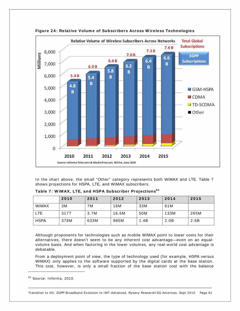
Transition to 4G: 3GPP Broadband Evolution to IMT-Advanced, Rysavy Research/3G Americas, Sept 2010 Page 61
Figure 24: Relative Volume of Subscribers Across Wireless Technologies
In the chart above, the small “Other” category represents both WiMAX and LTE. Table 7 shows projections for HSPA, LTE, and WiMAX subscribers.
Table 7: WiMAX, LTE, and HSPA Subscriber Projections82
2010 2011 2012 2013 2014 2015
WiMAX 3M 7M 16M 33M 61M
LTE 317T 3.7M 16.6M 50M 133M 265M
HSPA 378M 633M 985M 1.4B 2.0B 2.6B
Although proponents for technologies such as mobile WiMAX point to lower costs for their alternatives, there doesn’t seem to be any inherent cost advantage—even on an equal-volume basis. And when factoring in the lower volumes, any real-world cost advantage is debatable.
From a deployment point of view, the type of technology used (for example, HSPA versus WiMAX) only applies to the software supported by the digital cards at the base station. This cost, however, is only a small fraction of the base station cost with the balance
82 Source: Informa, 2010.

Transition to 4G: 3GPP Broadband Evolution to IMT-Advanced, Rysavy Research/3G Americas, Sept 2010 Page 62
covering antennas, power amplifiers, cables, racks, RF cards. As for the rest of the network including construction, backhaul, and core-network components, costs are similar regardless of Radio Access Network (RAN) technology. Spectrum costs for each technology can differ greatly depending on a country’s regulations and the spectrum band. As a general rule in most parts of the world, spectrum sold at 3.5 GHz will cost much less than spectrum sold at 850 MHz (all other things being equal).
As for UMTS-HSPA versus CDMA2000, higher deployment—by a factor of five—could translate to significant cost savings. For example, research and development amortization results in a four-to-one difference in base station costs.83 Similarly, just as GSM handsets are considered much less expensive than 1xRTT handsets, UMTS-HSPA wholesale terminal prices could be the market leader in low-cost or mass-market 3G terminals.
Even LTE is on the road to a robust wireless ecosystem and significant economies of scale. In June of 2008, the Next Generation Mobile Networks alliance (NGMN) confirmed its selection of LTE. Dr. Peter Meissner, Operating Officer of NGMN announced that “based on intensive and detailed technology evaluations, 3GPP LTE is the first technology which broadly meets its recommendations and is approved by its Board.”84 The NGMN is comprised of 18 mobile network operators, 29 vendor sponsors and 3 University research institutes. Its operator members include: Alltel, AT&T, China Mobile, France Telecom, Royal KPN, MSV Mobile Satellite Ventures, NTT DoComo, Reliance Communications, SK Telecom, Telecom Italia, Telefonica, Telenor, TeliaSonera, Telstra, Telus, T-Mobile and Vodafone.
Competitive Summary Based on the information presented in this paper, Table 8 summarizes the competitive position of the different technologies discussed.
Table 8: Competitive Position of Major Wireless Technologies
Technology EDGE/HSPA/LTE CDMA2000 WiMAX
Subscribers Over 4.4 billion 518 million85 today; slower growth expected than GSM-HSPA
61 million anticipated by 2014
Maturity Extremely mature Extremely mature Emerging
Adoption Cellular operators globally
Cellular operators globally
Limited to date
Coverage/Footprint Global Global with the general exception of Western Europe
Limited
Deployment Fewer cell sites required at 700 and 850 MHz
Fewer cell sites required at 700 and 850 MHz
Many more cell sites required at 2.5 GHz
83 Source: 3G Americas’ member analysis. 84 http://www.umts-forum.org/content/view/2479/172/. 85 Source: CDG, July 2010 for Q4 2009.

Transition to 4G: 3GPP Broadband Evolution to IMT-Advanced, Rysavy Research/3G Americas, Sept 2010 Page 63
Technology EDGE/HSPA/LTE CDMA2000 WiMAX
Devices Broad selection of GSM/EDGE/UMTS/ HSPA devices
Broad selection of 1xRTT/EV-DO devices
Initial devices emphasize data
Radio Technology Highly optimized TDMA for EDGE, highly optimized CDMA for HSPA, highly optimized OFDMA for LTE
Highly optimized CDMA for Rev 0/A/B
Optimized OFDMA in Release 1.0. More optimized in Release 1.5
Spectral Efficiency Very high with HSPA, matches OFDMA approaches in 5 MHz with HSPA+
Very high with EV-DO Rev A/B
Very high, but not higher than HSPA+ for Release 1.0, and not higher than LTE for Release 1.5
Throughput Capabilities
Peak downlink user-achievable rates of over 4 Mbps today with achievable rates of over 8 Mbps today with HSPA+
Peak downlink user-achievable rates of over 1.5 Mbps, with significantly higher rates in the future
3 to 6 Mbps typical rates with bursts to 10 Mbps
Voice Capability Extremely efficient circuit-voice available today; smoothest migration to VoIP of any technology
Extremely efficient circuit-voice available today
EV-DO radio channels with VoIP cannot support circuit-voice users
Relatively inefficient VoIP initially; more efficient in later stages, but lower than LTE
Voice coverage will be much more limited than cellular
Simultaneous Voice and Data
Available with GSM86 and UMTS today
Not available today
Available with VoIP and future devices
Potentially available, though initial services will emphasize data
Efficient Spectrum Usage
Entire UMTS radio channel available for any mix of voice and high-speed data
Radio channel today limited to either voice/medium speed data or high-speed data only
Currently only efficient for data-centric networks
86 With the application of Dual Transfer Mode.

Transition to 4G: 3GPP Broadband Evolution to IMT-Advanced, Rysavy Research/3G Americas, Sept 2010 Page 64
Conclusion In 2010, the mobile broadband industry surged with data-hungry smartphones on track to becoming the most common phone type in developed countries, with innovative new devices such as the Apple iPad, with 3G becoming ubiquitous in developed countries, and with advanced wireless technologies such as LTE seeing initial deployment. The growing success of mobile broadband, however, has mandated the means of augmenting capacity to which the industry has responded by using more efficient technologies, deploying more cell sites, and offloading onto either Wi-Fi or femtocells. Governments have responded by vigorous plans to supply more spectrum.
Through constant innovation, the EDGE/HSPA/LTE family of technologies has proven itself as the predominant wireless network solution and offers operators and subscribers a true mobile-broadband advantage. The continued use of GSM and EDGE technology through ongoing enhancements allows operators to leverage existing investments. With UMTS-HSPA, the technologies’ advantages provide for broadband services that will deliver increased data revenue and provide a path to all-IP architectures. With LTE now the most widely chosen technology platform for the forthcoming decade and with deployment imminent, the advantages offer a best-of-breed, long-term solution that matches or exceeds the performance of competing approaches.
The migration to 4G, however, is a long-term one. Until the middle of this decade, most subscribers will be using 2G and 3G. Significant uptake of LTE will not occur until the second half of this decade.
Today, HSPA offers the highest peak data rates of any widely available, wide-area wireless technology. With continued evolution, peak data rates will continue to increase, spectral efficiency will improve, and latency will decrease. The result is support for more users with more supported applications. The scope of applications will also increase as new services through standardized network interfaces become available such as location information, video, and call control. Greater efficiencies and capabilities translate to more competitive offers, greater network usage, and increased revenues.
Because of practical benefits and deployment momentum, the migration path from EDGE to HSPA, and then to LTE is proving inevitable. Benefits include the ability to roam globally, huge economies of scale, widespread acceptance by operators, complementary services such as messaging and multimedia, and an astonishing variety of competitive handsets and other devices. Currently more than 347 commercial UMTS-HSPA networks are already in operation. UMTS-HSPA and/or LTE offer an excellent migration path for GSM operators, as well as an effective technology solution for greenfield operators.
HSPA has significantly enhanced UMTS by providing a broadband data service with user-achievable rates that often exceed 1 Mbps on the downlink in initial deployments and that now exceed 4 Mbps in some commercial networks. Many networks are now being upgraded to include HSUPA providing users with uplink rates in excess of 1 Mbps. HSPA+ increases rates further, with typical rates between 1.9 and 8.8 Mbps anticipated in early versions of the technology (based on 64 QAM). Speeds will only increase as operators implement other HSPA+ innovations such as Dual-Carrier, Multi-Carrier, and MIMO.
Not only expected continual improvements in radio technology, but improvements to the core network through flatter architectures—particularly EPC—will reduce latency, speed applications, simplify deployment, enable all services in the IP domain, and allow a common core network to support both LTE and legacy GSM-HSPA systems.
Other innovations, such as MIMO and higher order modulation are now being deployed. Evolved HSPA+ systems, with peak rates of 42 Mbps, will largely match the throughput and

Transition to 4G: 3GPP Broadband Evolution to IMT-Advanced, Rysavy Research/3G Americas, Sept 2010 Page 65
capacity of OFDMA-based approaches in 5 MHz, 3GPP adopted OFDMA with 3GPP LTE, which will provide a growth platform for the next decade.
With the continued growth in mobile computing, powerful new handheld-computing platforms, an increasing amount of mobile content, multimedia messaging, mobile commerce, and location services, wireless data has slowly, but inevitably, become a huge industry. EDGE/HSPA/LTE provides one of the most robust portfolios of mobile-broadband technologies, and it is an optimum framework for realizing the potential of this market.

Transition to 4G: 3GPP Broadband Evolution to IMT-Advanced, Rysavy Research/3G Americas, Sept 2010 Page 66
Appendix: Technology Details The EDGE/HSPA/LTE family of data technologies provides ever-increasing capabilities that support ever more demanding applications. EDGE, now available globally, already makes a wealth of applications feasible including enterprise applications, messaging, e-mail, Web browsing, consumer applications, and even some multimedia applications. With UMTS and HSPA, users are enjoying videophones, high-fidelity music, richer multimedia applications, and efficient access to their enterprise applications.
It is important to understand the needs enterprises and consumers have for these services. The obvious needs are broad coverage and high data throughput. Less obvious for users, but as critical for effective application performance, are the needs for low latency, QoS control, and spectral efficiency. Spectral efficiency, in particular, is of paramount concern, because it translates to higher average throughputs (and thus more responsive applications) for more active users in a coverage area. The discussion below, which examines each technology individually, details how the progression from EDGE to HSPA to LTE is one of increased throughput, enhanced security, reduced latency, improved QoS, and increased spectral efficiency.
It is also helpful to specifically note the throughput requirements necessary for different applications:
Microbrowsing (for example, Wireless Application Protocol [WAP]): 8 to 128 kbps
Multimedia messaging: 8 to 64 kbps
Video telephony: 64 to 384 kbps
General-purpose Web browsing: 32 kbps to more than 1 Mbps
Enterprise applications including e-mail, database access, and Virtual Private Networks (VPNs): 32 kbps to more than 1 Mbps
Video and audio streaming: 32 kbps to 2 Mbps
Note that EDGE already satisfies the demands of many applications. With HSPA, applications operate faster and the range of supported applications expands even further.
Under favorable conditions, EDGE delivers peak user-achievable throughput rates close to 200 kbps and initial deployments of HSPA deliver peak user-achievable downlink throughput rates of well over 1 Mbps, easily meeting the demands of many applications. Latency has continued to improve, too, with HSPA networks today having round-trip times as low as 70 msec. The combination of low latency and high throughput translates to a broadband experience for users in which applications are extremely responsive.
Increasingly, devices will be multi-modal, supporting multiple types of wireless technologies. Users equipped with such multimode devices may, therefore, be granted quite different levels of connectivity ranging from a dense urban environment in which they may obtain the latest wireless technology to slower speeds in a rural network deployment or when roaming in a visited network. In these cases, users will benefit from knowing what service level to expect such as from indications on the device screen. These are currently available at a rudimentary level (e.g., 2G vs. 3G), but future improvements will enable display of additional details (e.g., Evolved EDGE vs. EDGE, HSUPA).
Complementarily, operators are given tools, via the Universal Integrated Circuit Card (UICC) SIM (USIM) application toolkit, for steering devices to the appropriate network or wireless technology so that mobile users can seamlessly be supplied with the most suitable network connectivity when roaming outside their home network.

Transition to 4G: 3GPP Broadband Evolution to IMT-Advanced, Rysavy Research/3G Americas, Sept 2010 Page 67
In this section, we consider different technical approaches for wireless and the parallel evolution of 3GPP technologies. We then provide details on EDGE, UMTS-HSPA, HSPA+, LTE, and supporting technologies such as IMS.
Spectrum Bands 3GPP technologies operate in a wide range of radio bands. As new spectrum becomes available, 3GPP updates its specifications for these bands.
It should be noted that although the support of a new frequency band may be introduced in a particular release, the 3GPP standard also specifies ways to implement devices and infrastructure operating on any frequency band, according to release anterior to the introduction of that particular frequency band. For example, although band 5 (US Cellular Band) was introduced in Release 6, the first devices operating on this band were compliant with the release 5 of the standard.
Table 9 shows the UMTS FDD bands.
Table 9: UMTS FDD Bands87
Operating Band
UL FrequenciesUE transmit, Node B receive
DL frequencies UE receive, Node B transmit
I 1920 - 1980 MHz 2110 -2170 MHz II 1850 -1910 MHz 1930 -1990 MHz III 1710-1785 MHz 1805-1880 MHz IV 1710-1755 MHz 2110-2155 MHz V 824 - 849MHz 869-894MHz VI 830-840 MHz 875-885 MHz VII 2500 - 2570 MHz 2620 - 2690 MHz VIII 880 - 915 MHz 925 - 960 MHz IX 1749.9 - 1784.9 MHz 1844.9 - 1879.9 MHz X 1710-1770 MHz 2110-2170 MHz XI 1427.9 - 1447.9 MHz 1475.9 - 1495.9 MHz XII 698 - 716 MHz 728 - 746 MHz XIII 777 - 787 MHz 746 - 756 MHz XIV 788 - 798 MHz 758 - 768 MHz XV Reserved Reserved XVI Reserved Reserved XVII Reserved Reserved XVIII Reserved Reserved XIX 830 – 845 MHz 875 -890 MHz XX 832 - 862 MHz 791 - 821 MHz XXI 1447.9 - 1462.9 MHz 1495.9 - 1510.9 MHz
UMTS TDD bands are the same as the LTE TDD bands. Table 10 shows the LTE FDD and TDD bands.
87 Source: 3GPP Technical Specification 25.104, V9.4.0

Transition to 4G: 3GPP Broadband Evolution to IMT-Advanced, Rysavy Research/3G Americas, Sept 2010 Page 68
Table 10: LTE FDD and TDD bands88
E-UTRA Operating
Band
Uplink (UL) operating bandBS receive UE transmit
Downlink (DL) operating band BS transmit UE receive
Duplex Mode
FUL_low – FUL_high FDL_low – FDL_high
1 1920 MHz – 1980 MHz 2110 MHz – 2170 MHz FDD 2 1850 MHz – 1910 MHz 1930 MHz – 1990 MHz FDD 3 1710 MHz – 1785 MHz 1805 MHz – 1880 MHz FDD 4 1710 MHz – 1755 MHz 2110 MHz – 2155 MHz FDD 5 824 MHz – 849 MHz 869 MHz – 894MHz FDD 61 830 MHz – 840 MHz 875 MHz – 885 MHz FDD 7 2500 MHz – 2570 MHz 2620 MHz – 2690 MHz FDD 8 880 MHz – 915 MHz 925 MHz – 960 MHz FDD 9 1749.9 MHz – 1784.9 MHz 1844.9 MHz – 1879.9 MHz FDD
10 1710 MHz – 1770 MHz 2110 MHz – 2170 MHz FDD 11 1427.9 MHz – 1447.9 MHz 1475.9 MHz – 1495.9 MHz FDD 12 698 MHz – 716 MHz 728 MHz – 746 MHz FDD 13 777 MHz – 787 MHz 746 MHz – 756 MHz FDD 14 788 MHz – 798 MHz 758 MHz – 768 MHz FDD 15 Reserved Reserved FDD 16 Reserved Reserved FDD 17 704 MHz – 716 MHz 734 MHz – 746 MHz FDD 18 815 MHz – 830 MHz 860 MHz – 875 MHz FDD 19 830 MHz – 845 MHz 875 MHz – 890 MHz FDD 20 832 MHz – 862 MHz 791 MHz – 821 MHz 21 1447.9 MHz – 1462.9 MHz 1495.9 MHz – 1510.9 MHz FDD ... 33 1900 MHz – 1920 MHz 1900 MHz – 1920 MHz TDD 34 2010 MHz – 2025 MHz 2010 MHz – 2025 MHz TDD 35 1850 MHz – 1910 MHz 1850 MHz – 1910 MHz TDD 36 1930 MHz – 1990 MHz 1930 MHz – 1990 MHz TDD 37 1910 MHz – 1930 MHz 1910 MHz – 1930 MHz TDD 38 2570 MHz – 2620 MHz 2570 MHz – 2620 MHz TDD 39 1880 MHz – 1920 MHz 1880 MHz – 1920 MHz TDD 40 2300 MHz – 2400 MHz 2300 MHz – 2400 MHz TDD
Note 1: Band 6 is not applicable.
EDGE/EGPRS Today, most GSM networks support EDGE. It is an enhancement applicable to GPRS, which is the original packet data service for GSM networks, as well as to GSM circuit-switched services, the latter not being considered further in this document. GPRS provides a packet-based IP connectivity solution supporting a wide range of enterprise and consumer applications. GSM networks with EDGE operate as wireless extensions to the Internet and give users Internet access, as well as access to their organizations from anywhere. With peak user-achievable89 throughput rates of up to 200 kbps with EDGE using four timeslot devices, users have the same effective access speed as a modem, but with the convenience of connecting from anywhere.
88 Source: 3GPP Technical Specification 36.104, V9.4.0. 89 “Peak user-achievable” means users, under favorable conditions of network loading and signal propagation, can achieve this rate as measured by applications such as file transfer. Average rates depend on many factors and will be lower than these rates.

Transition to 4G: 3GPP Broadband Evolution to IMT-Advanced, Rysavy Research/3G Americas, Sept 2010 Page 69
To understand the evolution of data capability, we briefly examine how these data services operate, beginning with the architecture of GSM and EDGE, as depicted in Figure 25.
Figure 25: GSM/GPRS/EDGE Architecture
EDGE is essentially the addition of a packet-data infrastructure to GSM. In fact, this same data architecture is preserved in UMTS and HSPA networks, and it is technically referred to as GPRS for the core-data function in all of these networks. The term GPRS may also be used to refer to the initial radio interface, now supplanted by EDGE. Functions of the data elements are as follows:
1. The base station controller directs/receives packet data to/from the Serving GPRS Support Node (SGSN), an element that authenticates and tracks the location of mobile stations.
2. The SGSN performs the types of functions for data that the Mobile Switching Center (MSC) performs for voice. Each serving area has one SGSN, and it is often collocated with the MSC.
3. The SGSN forwards/receives user data to/from the Gateway GPRS Support Node (GGSN), which can be viewed as a mobile IP router to external IP networks. Typically, there is one GGSN per external network (for example, the Internet). The GGSN also manages IP addresses, dynamically assigning them to mobile stations for their data sessions.
Another important element is the Home Location Register (HLR), which stores users’ account information for both voice and data services. Of significance is that this same data architecture supports data services in GSM and in UMTS-HSPA networks, thereby simplifying operator network upgrades.
In the radio link, GSM uses radio channels of 200 kilohertz (kHz) width, divided in time into eight timeslots comprising 577 microseconds (s) that repeat every 4.6 msec, as shown in Figure 26. The network can have multiple radio channels (referred to as transceivers) operating in each cell sector. The network assigns different functions to each timeslot such as the Broadcast Control Channel (BCCH), circuit-switched functions like voice calls or data calls, the optional Packet Broadcast Control Channel (PBCCH), and packet data channels. The network can dynamically adjust capacity between voice and data functions, and it can also reserve minimum resources for each service. This enables more data traffic when voice traffic is low or, likewise, more voice traffic when data traffic
Public SwitchedTelephone Network
External DataNetwork (e.g., Internet)
BaseStation
Controller
BaseTransceiver
Station
BaseTransceiver
Station
MobileSwitching
CenterHome
LocationRegister
ServingGPRS
SupportNode
GatewayGPRS
SupportNode
IPTraffic
Circuit-Switched Traffic
MobileStation
MobileStation
MobileStation
GPRS/EDGE DataInfrastructure
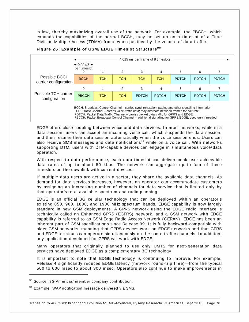
Transition to 4G: 3GPP Broadband Evolution to IMT-Advanced, Rysavy Research/3G Americas, Sept 2010 Page 70
is low, thereby maximizing overall use of the network. For example, the PBCCH, which expands the capabilities of the normal BCCH, may be set up on a timeslot of a Time Division Multiple Access (TDMA) frame when justified by the volume of data traffic.
Figure 26: Example of GSM/EDGE Timeslot Structure90
EDGE offers close coupling between voice and data services. In most networks, while in a data session, users can accept an incoming voice call, which suspends the data session, and then resume their data session automatically when the voice session ends. Users can also receive SMS messages and data notifications91 while on a voice call. With networks supporting DTM, users with DTM-capable devices can engage in simultaneous voice/data operation.
With respect to data performance, each data timeslot can deliver peak user-achievable data rates of up to about 50 kbps. The network can aggregate up to four of these timeslots on the downlink with current devices.
If multiple data users are active in a sector, they share the available data channels. As demand for data services increases, however, an operator can accommodate customers by assigning an increasing number of channels for data service that is limited only by that operator’s total available spectrum and radio planning.
EDGE is an official 3G cellular technology that can be deployed within an operator's existing 850, 900, 1800, and 1900 MHz spectrum bands. EDGE capability is now largely standard in new GSM deployments. A GPRS network using the EDGE radio interface is technically called an Enhanced GPRS (EGPRS) network, and a GSM network with EDGE capability is referred to as GSM Edge Radio Access Network (GERAN). EDGE has been an inherent part of GSM specifications since Release 99. It is fully backward-compatible with older GSM networks, meaning that GPRS devices work on EDGE networks and that GPRS and EDGE terminals can operate simultaneously on the same traffic channels. In addition, any application developed for GPRS will work with EDGE.
Many operators that originally planned to use only UMTS for next-generation data services have deployed EDGE as a complementary 3G technology.
It is important to note that EDGE technology is continuing to improve. For example, Release 4 significantly reduced EDGE latency (network round-trip time)—from the typical 500 to 600 msec to about 300 msec. Operators also continue to make improvements in
90 Source: 3G Americas’ member company contribution. 91 Example: WAP notification message delivered via SMS.
BCCH TCH TCH TCH TCH PDTCH PDTCH PDTCH
0 1 2 3 4 5 6 7
577 Sper timeslot
4.615 ms per frame of 8 timeslots
Possible BCCH carrier configuration
PBCCH TCH TCH PDTCH PDTCH PDTCH PDTCH PDTCH
0 1 2 3 4 5 6 7
Possible TCH carrier configuration
BCCH: Broadcast Control Channel – carries synchronization, paging and other signalling informationTCH: Traffic Channel – carries voice traffic data; may alternate between frames for half-ratePDTCH: Packet Data Traffic Channel – carries packet data traffic for GPRS and EDGEPBCCH: Packet Broadcast Control Channel – additional signalling for GPRS/EDGE; used only if needed

Transition to 4G: 3GPP Broadband Evolution to IMT-Advanced, Rysavy Research/3G Americas, Sept 2010 Page 71
how EDGE functions including network optimizations that boost capacity and reduce latency. The impact for users is that EDGE networks today are more robust with applications functioning more responsively. Release 7’s Evolved EDGE also introduces significant new features.
Devices themselves are increasing in capability. Dual Transfer Mode (DTM) devices, already available from vendors, allow simultaneous voice and data communications. For example, during a voice call, users will be able to retrieve e-mail, do multimedia messaging, browse the Web, and do Internet conferencing. This is particularly useful when connecting phones to laptops via cable or Bluetooth and using them as modems.
DTM is a 3GPP-specified technology that enables new applications like video sharing while providing a consistent service experience (service continuity) with UMTS. Typically, a DTM end-to-end solution requires only a software upgrade to the GSM/EDGE radio network. There are a number of networks and devices now supporting DTM.
Evolved EDGE Recognizing the value of the huge installed base of GSM networks, 3GPP has worked to improve EDGE capabilities for Release 7. This work was part of the GERAN Evolution effort, which also includes voice enhancements not discussed in this paper.
Although EDGE today already serves many applications like wireless e-mail extremely well, it makes good sense to continue to evolve EDGE capabilities. From an economic standpoint, it is less costly than upgrading to UMTS, because most enhancements are designed to be software based, and it is highly asset-efficient, because it involves fewer long-term capital investments to upgrade an existing system. With 85 percent of the world market using GSM, which is already equipped for simple roaming and billing, it is easy to offer global service to subscribers. Evolved EDGE offers higher data rates and system capacity, and reduced latency, and cable-modem speeds are realistically achievable.
In addition, many regions do not have licensed spectrum for deployment of a new radio technology such as UMTS-HSPA or LTE. Also, Evolved EDGE provides better service continuity between EDGE and HSPA or LTE, meaning that a user will not have a hugely different experience when moving between environments, for example when an LTE user moves to a GSM/Evolved EDGE network to establish a (circuit-switched) voice call92 or when leaving LTE coverage.
Although GSM and EDGE are already highly optimized technologies, advances in radio techniques will enable further efficiencies. Some of the objectives of Evolved EDGE included:
A 100 percent increase in peak data rates.
A 50 percent increase in spectral efficiency and capacity in C/I-limited scenarios.
A sensitivity increase in the downlink of 3 dB for voice and data.
A reduction of latency for initial access and round-trip time, thereby enabling support for conversational services such as VoIP and PoC.
To achieve compatibility with existing frequency planning, thus facilitating deployment in existing networks.
92 Some initial LTE networks will be data-only, with voice operation provided by GSM.

Transition to 4G: 3GPP Broadband Evolution to IMT-Advanced, Rysavy Research/3G Americas, Sept 2010 Page 72
To coexist with legacy mobile stations by allowing both old and new stations to share the same radio resources.
To avoid impacts on infrastructure by enabling improvements through a software upgrade.
To be applicable to DTM (simultaneous voice and data) and the A/Gb mode interface. The A/Gb mode interface is part of the 2G core network, so this goal is required for full backward-compatibility with legacy GPRS/EDGE.
The methods standardized in Release 7 to achieve or surpass these objectives include:
Downlink dual-carrier reception to double the number of timeslots that can be received for a 100 percent increase in throughput.
The addition of Quadrature Phase Shift Keying (QPSK), 16 QAM and 32 QAM, as well as an increased symbol rate (1.2x) and a new set of modulation/coding schemes that will increase maximum throughput per timeslot by up to 100 percent (EGPRS2-B). Currently, EDGE uses 8-PSK modulation.
A reduction in overall latency. This is achieved by lowering the Transmission Time Interval (TTI) to 10 msec and by including the acknowledgement information in the data packet. These enhancements will have a dramatic effect on throughput for many applications.
Downlink diversity reception of the same radio channel to increase the robustness in interference and to improve the receiver sensitivity. Simulations have demonstrated sensitivity gains of 3 dB and a decrease in required Carrier-to-Intermodulation Ratio (C/I) of up to 18 dB for a single co-channel interferer. Significant increases in system capacity can be achieved, as explained below.
Dual-Carrier Receiver
A key part of the evolution of EDGE is the utilization of more than one radio frequency carrier. This overcomes the inherent limitation of the narrow channel bandwidth of GSM. Using two radio-frequency carriers requires two receiver chains in the downlink, as shown in Figure 27. Using two carriers enables the reception of twice (or more than twice for some multi-slot classes) as many radio blocks simultaneously.
Figure 27: Evolved EDGE Two-Carrier Operation93
93 Source: 3G Americas’ member company contribution.
Rx1
Tx (1)
Neighbor Cell Measurements
Uplink Timeslot
Downlink Timeslot
Slot NSlot N + 1
(Idle Frame) Slot N + 2 Slot N + 3
Rx2

Transition to 4G: 3GPP Broadband Evolution to IMT-Advanced, Rysavy Research/3G Americas, Sept 2010 Page 73
Alternatively, the original number of radio blocks can be divided between the two carriers. This eliminates the need for the network to have contiguous timeslots on one frequency.
Figure 28: EDGE Multi-Carrier Receive Logic – Mobile Part94
Channel capacity with dual-carrier reception improves greatly, not by increasing basic efficiencies of the air interface, but because of statistical improvement in the ability to assign radio resources, which increases trunking efficiency.
As network loading increases, it is statistically unlikely that contiguous timeslots will be available. With today’s EDGE devices, it is not possible to change radio frequencies when going from one timeslot to the next. With an Evolved EDGE dual receiver, however, this becomes possible, thus enabling contiguous timeslots across different radio channels. The result is that the system can allocate a larger set of time slots for data even if they are not contiguous, which otherwise is not possible. Figure 29 shows why this is important. As the network becomes busy, the probability of being assigned 1 timeslot decreases. As this probability decreases (X axis), the probability of being able to obtain 5 timeslots on the same radio carrier decreases dramatically. Being able to obtain timeslots across two carriers in Evolved EDGE, however, significantly improves the likelihood of obtaining the desired timeslots.
94 Source: 3G Americas’ member company contribution.

Transition to 4G: 3GPP Broadband Evolution to IMT-Advanced, Rysavy Research/3G Americas, Sept 2010 Page 74
Figure 29: Probabilities of Time Slot Assignments95
Mobile Station Receive Diversity
Figure 30 illustrates how mobile-station receive diversity increases system capacity. (BCCH refers to the Broadcast Control Channel and TCH refers to the Traffic Channel.) The BCCH carrier repeats over 12 cells in a 4/12 frequency reuse pattern, which requires 2.4 MHz for GSM. A fractionally loaded system may repeat f12 through f15 on each of the cells. This is a 1/1 frequency reuse pattern with higher system utilization, but also potentially high co-channel interference in loaded conditions.
Figure 30: Example of 4/12 Frequency Reuse with 1/1 Overlay96
95 Source: 3G Americas’ member company contribution. 96 Source: 3G Americas’ member company contribution.
0 1
2 3 4
56 7
8
9 10
11
Example of a 4/12 frequency reuse pattern used for BCCH carriers with a 1/1 frequency reuse pattern for TCH carriers.
BCCH carriers on f0 - f11 are associated
with TCH carrier frequencies f12 – f15
f12f13f14f15
f12f13f14f15
f12f13f14f15
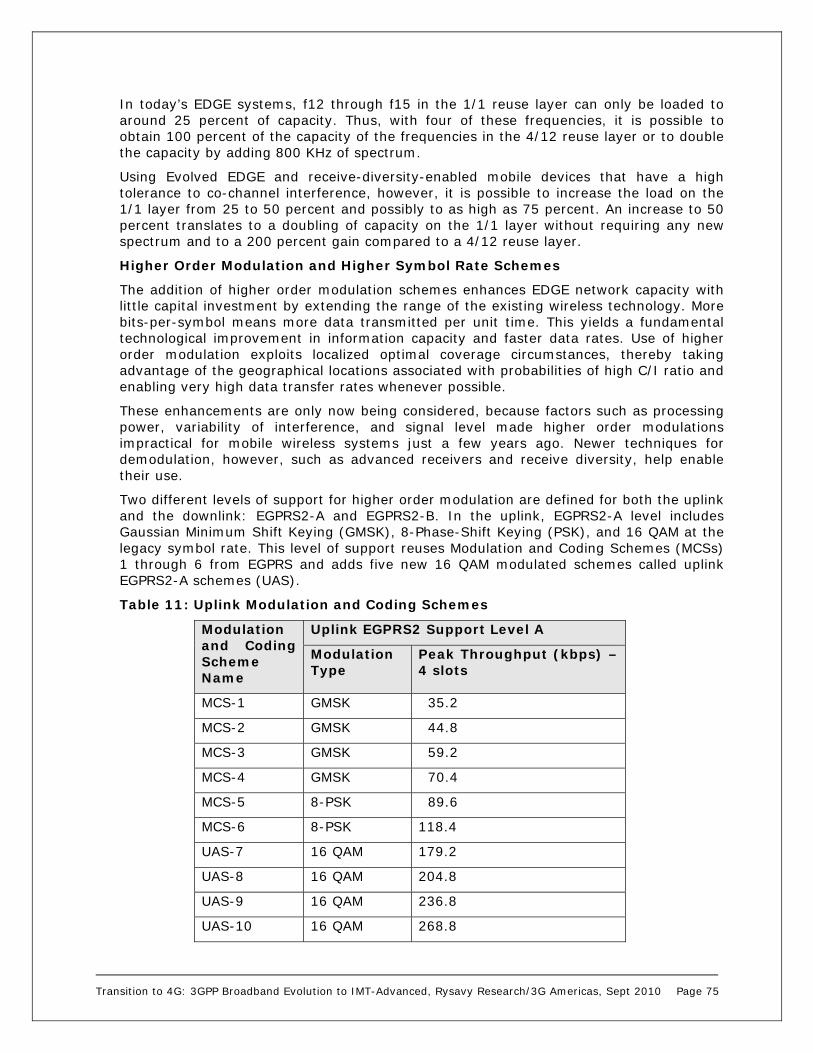
Transition to 4G: 3GPP Broadband Evolution to IMT-Advanced, Rysavy Research/3G Americas, Sept 2010 Page 75
In today’s EDGE systems, f12 through f15 in the 1/1 reuse layer can only be loaded to around 25 percent of capacity. Thus, with four of these frequencies, it is possible to obtain 100 percent of the capacity of the frequencies in the 4/12 reuse layer or to double the capacity by adding 800 KHz of spectrum.
Using Evolved EDGE and receive-diversity-enabled mobile devices that have a high tolerance to co-channel interference, however, it is possible to increase the load on the 1/1 layer from 25 to 50 percent and possibly to as high as 75 percent. An increase to 50 percent translates to a doubling of capacity on the 1/1 layer without requiring any new spectrum and to a 200 percent gain compared to a 4/12 reuse layer.
Higher Order Modulation and Higher Symbol Rate Schemes
The addition of higher order modulation schemes enhances EDGE network capacity with little capital investment by extending the range of the existing wireless technology. More bits-per-symbol means more data transmitted per unit time. This yields a fundamental technological improvement in information capacity and faster data rates. Use of higher order modulation exploits localized optimal coverage circumstances, thereby taking advantage of the geographical locations associated with probabilities of high C/I ratio and enabling very high data transfer rates whenever possible.
These enhancements are only now being considered, because factors such as processing power, variability of interference, and signal level made higher order modulations impractical for mobile wireless systems just a few years ago. Newer techniques for demodulation, however, such as advanced receivers and receive diversity, help enable their use.
Two different levels of support for higher order modulation are defined for both the uplink and the downlink: EGPRS2-A and EGPRS2-B. In the uplink, EGPRS2-A level includes Gaussian Minimum Shift Keying (GMSK), 8-Phase-Shift Keying (PSK), and 16 QAM at the legacy symbol rate. This level of support reuses Modulation and Coding Schemes (MCSs) 1 through 6 from EGPRS and adds five new 16 QAM modulated schemes called uplink EGPRS2-A schemes (UAS).
Table 11: Uplink Modulation and Coding Schemes
Modulation and Coding Scheme Name
Uplink EGPRS2 Support Level A
Modulation Type
Peak Throughput (kbps) – 4 slots
MCS-1 GMSK 35.2
MCS-2 GMSK 44.8
MCS-3 GMSK 59.2
MCS-4 GMSK 70.4
MCS-5 8-PSK 89.6
MCS-6 8-PSK 118.4
UAS-7 16 QAM 179.2
UAS-8 16 QAM 204.8
UAS-9 16 QAM 236.8
UAS-10 16 QAM 268.8

Transition to 4G: 3GPP Broadband Evolution to IMT-Advanced, Rysavy Research/3G Americas, Sept 2010 Page 76
UAS-11 16 QAM 307.2
The second support level in the uplink includes QPSK, 16 QAM, and 32 QAM modulation as well as a higher (1.2x) symbol rate. MCSs 1 through 4 from EGPRS are reused, and eight new uplink EGPRS2-B schemes (UBS) are added.
Table 12: Uplink Modulation and Coding Schemes with Higher Symbol Rate
Modulation and Coding Scheme Name
Uplink EGPRS2 Support Level B
Modulation Type
Peak Throughput (kbps) – 4 slots
MCS-1 GMSK 35.2
MCS-2 GMSK 44.8
MCS-3 GMSK 59.2
MCS-4 GMSK 70.4
UBS-5 QPSK 89.6
UBS-6 QPSK 118.4
UBS-7 16 QAM 179.2
UBS-8 16 QAM 236.8
UBS-9 16 QAM 268.8
UBS-10 32 QAM 355.2
UBS-11 32 QAM 435.2
UBS-12 32 QAM 473.6
The first downlink support level introduces a modified set of 8-PSK coding schemes and adds 16 QAM and 32 QAM, all at the legacy symbol rate. Turbo codes are used for all new modulations. MCSs 1 through 4 are reused and eight new downlink EGPRS2-A level schemes (DAS) are added.
Table 13: Downlink Modulation and Coding Schemes
Modulation and Coding Scheme Name
Downlink HOM/HSR Support Level A
Modulation Type
Peak Throughput (kbps) – 4 slots
MCS-1 GMSK 35.2
MCS-2 GMSK 44.8
MCS-3 GMSK 59.2
MCS-4 GMSK 70.4
DAS-5 8-PSK 89.6
DAS-6 8-PSK 108.8
DAS-7 8-PSK 131.2
DAS-8 16 QAM 179.2

Transition to 4G: 3GPP Broadband Evolution to IMT-Advanced, Rysavy Research/3G Americas, Sept 2010 Page 77
DAS-9 16 QAM 217.6
DAS-10 32 QAM 262.4
DAS-11 32 QAM 326.4
DAS-12 32 QAM 393.6
The second downlink support level includes QPSK, 16 QAM, and 32 QAM modulations at a higher (1.2x) symbol rate. MCSs 1 through 4 are reused, and eight new downlink EGPRS2-B level schemes (DBS) are defined.
Table 14: Downlink Modulation and Coding Schemes with Higher Symbol Rate97
Modulation and Coding Scheme Name
Downlink HOM/HSR Support Level B
Modulation Type
Peak Throughput (kbps) – 4 slots
MCS-1 GMSK 35.2
MCS-2 GMSK 44.8
MCS-3 GMSK 59.2
MCS-4 GMSK 70.4
DBS-5 QPSK 89.6
DBS-6 QPSK 118.4
DBS-7 16 QAM 179.2
DBS-8 16 QAM 236.8
DBS-9 16 QAM 268.8
DBS-10 32 QAM 355.2
DBS-11 32 QAM 435.2
DBS-12 32 QAM 473.6
The combination of Release 7 Evolved EDGE enhancements shows a dramatic potential increase in throughput. For example, in the downlink, a Type 2 mobile device (one that can support simultaneous transmission and reception) using DBS-12 as the MCS and a dual-carrier receiver can achieve the following performance:
Highest data rate per timeslot (layer 2) = 118.4 kbps
Timeslots per carrier = 8
Carriers used in the downlink = 2
Total downlink data rate = 118.4 kbps X 8 X 2 = 1894.4 kbps98
97 These data rates require a wide-pulse shaping filter that is not part of Release 7. 98 For the near future, two carriers will be a scenario more practically realized on a notebook computer platform than handheld platforms.

Transition to 4G: 3GPP Broadband Evolution to IMT-Advanced, Rysavy Research/3G Americas, Sept 2010 Page 78
This translates to a peak network rate close to 2 Mbps and a user-achievable data rate of well over 1 Mbps!
Evolved EDGE Implementation
Table 15 shows what is involved in implementing the different features defined for Evolved EDGE. For a number of features, there are no hardware changes required for the base transceiver station (BTS). For all features, Evolved EDGE is compatible with legacy frequency planning.
Table 15: Evolved EDGE Implementation99
In conclusion, it is interesting to note the sophistication and capability that is achievable with, and planned for, by GSM.
UMTS-HSPA Technology UMTS has garnered the overwhelming majority of new 3G spectrum licenses with 283 commercial networks already in operation.100 Compared to emerging wireless technologies, UMTS technology is mature and benefits from research and development that began in the early 1990s. It has been thoroughly trialed, tested, and commercially deployed. UMTS deployment is now accelerating with stable network infrastructures and attractive, reliable mobile devices that have rich capabilities. With the addition of HSPA for high-speed packet data services, UMTS-HSPA is quickly emerging as the dominant global mobile-broadband network.
UMTS employs a wideband CDMA radio-access technology. The primary benefits of UMTS include high spectral efficiency for voice and data, simultaneous voice and data capability for users, high user densities that can be supported with low infrastructure costs, support for high-bandwidth data applications, and a clean migration to VoIP in the future.
99 Source: 3G Americas’ member company contribution. 100 Source: Informa Telecoms & Media, “World Cellular Information Service,” June 2009.

Transition to 4G: 3GPP Broadband Evolution to IMT-Advanced, Rysavy Research/3G Americas, Sept 2010 Page 79
Operators can also use their entire available spectrum for both voice and high-speed data services.
Additionally, operators can use a common core network that supports multiple radio-access networks including GSM, EDGE, WCDMA, HSPA, and evolutions of these technologies. This is called the UMTS multi-radio network, and it gives operators maximum flexibility in providing different services across their coverage areas (see Figure 31).
Figure 31: UMTS Multi-radio Network
The UMTS radio-access network consists of base stations referred to as Node B (corresponding to GSM base transceiver systems) that connect to RNCs (corresponding to GSM base station controllers [BSCs]). The RNCs connect to the core network as do the BSCs. When both GSM and WCDMA access networks are available, the network can hand over users between these networks. This is important for managing capacity, as well as in areas in which the operator has continuous GSM coverage, but has only deployed WCDMA in some locations.
Whereas GSM can effectively operate like a spread-spectrum system101, based on time division in combination with frequency hopping, WCDMA is a direct-sequence, spread-spectrum system. WCDMA is spectrally more efficient than GSM, but it is the wideband nature of WCDMA that provides its greatest advantage—the ability to translate the available spectrum into high data rates. This wideband technology approach results in the flexibility to manage multiple traffic types including voice, narrowband data, and wideband data.
WCDMA allocates different codes for different channels, whether for voice or data, and it can adjust the amount of capacity, or code space, of each channel every 10 msec with WCDMA Release 99 and every 2 msec with HSPA. WCDMA creates high-bandwidth traffic channels by reducing the amount of spreading (using a shorter code) with WCDMA Release 99 and higher-order modulation schemes for HSPA. Packet data users can share the same codes as other users, or the network can assign dedicated channels to users.
101 Spread spectrum systems can either be direct sequence or frequency hopping.
UMTSCore Network(MSC, HLR,
SGSN, GGSN)
GSM/EDGE
WCDMA,HSDPA
Othere.g., WLAN
Radio-Access Networks External Networks
Packet-SwitchedNetworks
Circuit-Switched Networks
Other CellularOperators

Transition to 4G: 3GPP Broadband Evolution to IMT-Advanced, Rysavy Research/3G Americas, Sept 2010 Page 80
To further expand the number of effectively operating applications, UMTS employs a sophisticated QoS architecture for data that provides four fundamental traffic classes including:
1. Conversational. Real-time, interactive data with controlled bandwidth and minimum delay such as VoIP or video conferencing.
2. Streaming. Continuous data with controlled bandwidth and some delay such as music or video.
3. Interactive. Back-and-forth data without bandwidth control and some delay such as Web browsing.
4. Background. Lower priority data that is non-real-time such as batch transfers.
This QoS architecture, available through all HSPA versions, involves negotiation and prioritization of traffic in the radio-access network, the core network, and the interfaces to external networks such as the Internet. Consequently, applications can negotiate QoS parameters on an end-to-end basis between a mobile terminal and a fixed-end system across the Internet or private intranets. This capability is essential for expanding the scope of supported applications, particularly multimedia applications including packetized video telephony and VoIP.
UMTS Release 99 Data Capabilities Initial UMTS network deployments were based on 3GPP Release 99 specifications, which included voice and data capabilities. Since then, Release 5 has defined HSDPA and Release 6 has defined HSUPA. With HSPA-capable devices, the network uses HSPA (HSDPA/HSUPA) for data. Operators with Release 99 networks are upgrading them to HSPA capability. In advance of Release 6, the uplink in HSDPA (Release 5) networks uses the Release 99 approach.
In UMTS Release 99, the maximum theoretical downlink rate is just over 2 Mbps. Although exact throughput depends on the channel sizes the operator chooses to make available, the capabilities of devices and the number of users active in the network limit the peak throughput rates a user can achieve to about 350 kbps in commercial networks. Peak downlink network speeds are 384 kbps. Uplink peak-network throughput rates are also 384 kbps in newer deployments with user-achievable peak rates of 350 kbps.102 This satisfies many communications-oriented applications.
Channel throughputs are determined by the amount of channel spreading. With more spreading, as in voice channels, the data stream has greater redundancy, and the operator can employ more channels. In comparison, a high-speed data channel has less spreading and fewer available channels. Voice channels use downlink spreading factors of 128 or 256, whereas a 384 kbps data channel uses a downlink spreading factor of 8. The commonly quoted rate of more than 2 Mbps downlink throughput for UMTS can be achieved by combining three data channels of 768 kbps, each with a spreading factor of 4.
WCDMA has lower network latency than EDGE, with about 100 to 200 msec measured in actual networks. Although UMTS Release 99 offers attractive data services, these services become much more efficient and more powerful with HSPA.
102 Initial UMTS networks had peak uplink rates of 64 kbps or 128 kbps, but many deployments emphasize 384 kbps.

Transition to 4G: 3GPP Broadband Evolution to IMT-Advanced, Rysavy Research/3G Americas, Sept 2010 Page 81
HSDPA HSPA refers to networks that support both HSDPA and HSUPA. All new deployments today are HSPA, and many operators have upgraded their HSDPA networks to HSPA. For example, in 2008, AT&T upgraded most of its network to HSPA. By the end of 2008, HSPA was deployed throughout the Americas. This section covers technical aspects of HSDPA, while the next section covers HSUPA.
HSDPA, specified in 3GPP Release 5, is a high-performance, packet-data service that delivers peak theoretical rates of 14 Mbps. Peak user-achievable throughput rates in initial deployments are well over 1 Mbps and as high as 4 Mbps in some networks. The same radio carrier can simultaneously service UMTS voice and data users, as well as HSDPA data users. HSDPA also has significantly lower latency, measured today on some networks as low as 70 msec on the data channel.
HSDPA achieves its high speeds through techniques similar to those that push EDGE performance past GPRS including higher order modulation, variable coding, and soft combining, as well as through the addition of powerful new techniques such as fast scheduling. The higher spectral efficiency and higher data rates not only enable new classes of applications, but also support a greater number of users accessing the network.
HSDPA achieves its performance gains from the following radio features:
High-speed channels shared in both code and time domains
Short TTI
Fast scheduling and user diversity
Higher order modulation
Fast link adaptation
Fast HARQ
These features function as follows:
High-Speed Shared Channels and Short Transmission Time Interval: First, HSDPA uses high-speed data channels called High Speed Physical Downlink Shared Channels (HS-PDSCH). Up to 15 of these channels can operate in the 5 MHz WCDMA radio channel. Each uses a fixed spreading factor of 16. User transmissions are assigned to one or more of these channels for a short TTI of 2 msec. The network can then readjust how users are assigned to different HS-PDSCH every 2 msec. The result is that resources are assigned in both time (the TTI interval) and code domains (the HS-PDSCH channels). Figure 32 illustrates different users obtaining different radio resources.

Transition to 4G: 3GPP Broadband Evolution to IMT-Advanced, Rysavy Research/3G Americas, Sept 2010 Page 82
Figure 32: High Speed–Downlink Shared Channels (Example)
Fast Scheduling and User Diversity: Fast scheduling exploits the short TTI by assigning users channels that have the best instantaneous channel conditions, rather than in a round-robin fashion. Because channel conditions vary somewhat randomly across users, most users can be serviced with optimum radio conditions and thereby obtain optimum data throughput. Figure 33 shows how a scheduler might choose between two users based on their varying radio conditions to emphasize the user with better instantaneous signal quality. With about 30 users active in a sector, the network achieves significant user diversity and significantly higher spectral efficiency. The system also makes sure that each user receives a minimum level of throughput. This approach is sometimes called proportional fair scheduling.
2 msec
Time
Cha
nne
liza
tion
Co
des
User 4User 3User 2User 1

Transition to 4G: 3GPP Broadband Evolution to IMT-Advanced, Rysavy Research/3G Americas, Sept 2010 Page 83
Figure 33: User Diversity
Higher Order Modulation: HSDPA uses both the modulation used in WCDMA—namely QPSK—and, under good radio conditions, an advanced modulation scheme—16 QAM. The benefit of 16 QAM is that 4 bits of data are transmitted in each radio symbol as opposed to 2 bits with QPSK. Data throughput is increased with 16 QAM, while QPSK is available under adverse conditions. HSPA Evolution will add 64 QAM modulation to further increase throughput rates. Note that 64 QAM was available in Release 7, and the combination of MIMO and 64 QAM became available this year in Release 8.
Fast Link Adaptation: Depending on the condition of the radio channel, different levels of forward-error correction (channel coding) can also be employed. For example, a three-quarter coding rate means that three quarters of the bits transmitted are user bits and one quarter are error-correcting bits. The process of selecting and quickly updating the optimum modulation and coding rate is referred to as fast link adaptation. This is done in close coordination with fast scheduling, as described above.
Fast Hybrid Automatic Repeat Request: Another HSDPA technique is Fast Hybrid Automatic Repeat Request (Fast Hybrid ARQ). “Fast” refers to the medium-access control mechanisms implemented in Node B (along with scheduling and link adaptation), as opposed to the BSC in GPRS/EDGE, and “hybrid” refers to a process of combining repeated data transmissions with prior transmissions to increase the likelihood of successful decoding. Managing and responding to real-time radio variations at the base station, as opposed to an internal network node, reduces delays and further improves overall data throughput.
Using the approaches just described, HSDPA maximizes data throughputs and capacity and minimizes delays. For users, this translates to better network performance under loaded conditions, faster application performance, a greater range of applications that function well, and increased productivity.
Field results validate the theoretical throughput results. With initial 1.8 Mbps peak-rate devices, vendors measured consistent throughput rates in actual deployments of more than 1 Mbps. These rates rose to more than 2 Mbps for 3.6 Mbps devices and are close to
High data rate
Low data rate
Time
User 2
User 1
User 2
User 1User 2User 1User 2User 1
Sig
nal
Qu
alit
y

Transition to 4G: 3GPP Broadband Evolution to IMT-Advanced, Rysavy Research/3G Americas, Sept 2010 Page 84
4 Mbps for 7.2 Mbps devices, assuming other portions of the network (for example, backhaul) can support the high throughput rates.
In 2008, typical devices supporting peak data rates of 3.6 Mbps or 7.2 Mbps became available. Many operator networks support 7.2 Mbps peak operation, and some even support the maximum rate of 14.4 Mbps.
HSPA technology is not standing still. Advanced radio technologies are becoming available. Among these technologies are mobile-receive diversity and equalization (for example, Minimum Mean Square Error [MMSE]), which improve the quality of the received radio signal prior to demodulation and decoding. This improvement enables not only higher peak HSDPA throughput speeds but makes these speeds available over a greater percentage of the coverage area.
HSUPA Whereas HSDPA optimizes downlink performance, HSUPA—which uses the Enhanced Dedicated Channel (E-DCH)—constitutes a set of improvements that optimizes uplink performance. Networks and devices supporting HSUPA became available in 2007. These improvements include higher throughputs, reduced latency, and increased spectral efficiency. HSUPA is standardized in Release 6. It results in an approximately 85 percent increase in overall cell throughput on the uplink and more than a 50 percent gain in user throughput. HSUPA also reduces packet delays, a significant benefit resulting in much improved application performance on HSPA networks
Although the primary downlink traffic channel supporting HSDPA serves as a shared channel designed for the support of services delivered through the packet-switched domain, the primary uplink traffic channel defined for HSUPA is a dedicated channel that could be used for services delivered through either the circuit-switched or the packet-switched domains. Nevertheless, by extension and for simplicity, the WCDMA-enhanced uplink capabilities are often identified in the literature as HSUPA.
Such an improved uplink benefits users in a number of ways. For instance, some user applications transmit large amounts of data from the mobile station such as sending video clips or large presentation files. For future applications like VoIP, improvements will balance the capacity of the uplink with the capacity of the downlink.
HSUPA achieves its performance gains through the following approaches:
An enhanced dedicated physical channel
A short TTI, as low as 2 msec, which allows faster responses to changing radio conditions and error conditions
Fast Node B-based scheduling, which allows the base station to efficiently allocate radio resources
Fast Hybrid ARQ, which improves the efficiency of error processing
The combination of TTI, fast scheduling, and Fast Hybrid ARQ also serves to reduce latency, which can benefit many applications as much as improved throughput. HSUPA can operate with or without HSDPA in the downlink, although it is likely that most networks will use the two approaches together. The improved uplink mechanisms also translate to better coverage and, for rural deployments, larger cell sizes.
HSUPA can achieve different throughput rates based on various parameters including the number of codes used, the spreading factor of the codes, the TTI value, and the transport block size in bytes.

Transition to 4G: 3GPP Broadband Evolution to IMT-Advanced, Rysavy Research/3G Americas, Sept 2010 Page 85
Initial devices enabled peak user rates of close to 2 Mbps as measured in actual network deployments. Future devices will ultimately approach speeds close to 5 Mbps, although only with the addition of interference cancellation methods that boost SNR.
Beyond throughput enhancements, HSUPA also significantly reduces latency. In optimized networks, latency will fall below 50 msec, relative to current HSDPA networks at 70 msec. And with a later introduction of a 2 msec TTI, latency will be as low as 30 msec.
Evolution of HSPA (HSPA+) OFDMA systems have attracted considerable attention through technologies such as 3GPP LTE and WiMAX. As already discussed in this paper, however, CDMA approaches can match OFDMA approaches in reduced channel bandwidths. The goal in evolving HSPA is to exploit available radio technologies—largely enabled by increases in digital signal processing power—to maximize CDMA-based radio performance. This not only makes HSPA competitive, it significantly extends the life of sizeable operator infrastructure investments.
Wireless and networking technologists have defined a series of enhancements for HSPA, some of which are specified in Release 7 and some of which are being finalized in Release 8. These include advanced receivers, MIMO, Continuous Packet Connectivity, Higher-Order Modulation and One Tunnel Architecture.
Advanced Receivers
One important area is advanced receivers for which 3GPP has specified a number of designs. These designs include Type 1, which uses mobile-receive diversity; Type 2, which uses channel equalization; and Type 3, which includes a combination of receive diversity and channel equalization. Type 3i devices, which are not yet available, will employ interference cancellation. Note that the different types of receivers are release-independent. For example, Type 3i receivers will work and provide a capacity gain in a Release 5 network.
The first approach is mobile-receive diversity. This technique relies on the optimal combination of received signals from separate receiving antennas. The antenna spacing yields signals that have somewhat independent fading characteristics. Hence, the combined signal can be more effectively decoded, which results in an almost doubling of downlink capacity when employed in conjunction with techniques such as channel equalization. Receive diversity is effective even for small devices such as PC Card modems and smartphones.
Current receiver architectures based on rake receivers are effective for speeds up to a few megabits per second. But at higher speeds, the combination of reduced symbol period and multipath interference results in inter-symbol interference and diminishes rake receiver performance. This problem can be solved by advanced-receiver architectures with channel equalizers that yield additional capacity gains over HSDPA with receive diversity. Alternate advanced-receiver approaches include interference cancellation and generalized rake receivers (G-Rake). Different vendors are emphasizing different approaches. The performance requirements for advanced-receiver architectures, however, are specified in 3GPP Release 6. The combination of mobile-receive diversity and channel equalization (Type 3) is especially attractive, because it results in a large capacity gain independent of the radio channel.
What makes such enhancements attractive is that the networks do not require any changes other than increased capacity within the infrastructure to support the higher bandwidth. Moreover, the network can support a combination of devices including both

Transition to 4G: 3GPP Broadband Evolution to IMT-Advanced, Rysavy Research/3G Americas, Sept 2010 Page 86
earlier devices that do not include these enhancements and later devices that do. Device vendors can selectively apply these enhancements to their higher performing devices.
MIMO
Another standardized capability is MIMO, a technique that employs multiple transmit antennas and multiple receive antennas, often in combination with multiple radios and multiple parallel data streams. The most common use of the term “MIMO” applies to spatial multiplexing. The transmitter sends different data streams over each antenna. Whereas multipath is an impediment for other radio systems, MIMO—as illustrated in Figure 34—actually exploits multipath, relying on signals to travel across different uncorrelated communications paths. This results in multiple data paths effectively operating somewhat in parallel and, through appropriate decoding, in a multiplicative gain in throughput.
Figure 34: MIMO Using Multiple Paths to Boost Throughput and Capacity
Tests of MIMO have proven very promising in WLANs operating in relative isolation in which interference is not a dominant factor. Spatial multiplexing MIMO should also benefit HSPA “hotspots” serving local areas such as airports, campuses, and malls, where the technology will increase capacity and peak data rates. In a fully loaded network with interference from adjacent cells, however, overall capacity gains will be more modest—in the range of 20 to 33 percent over mobile-receive diversity. Relative to a 1x1 antenna system, however, 2X2 MIMO can deliver cell throughput gains of about 80 percent. 3GPP has standardized spatial multiplexing MIMO in Release 7 using Double Transmit Adaptive Array (D-TxAA).103
Release 9 provides for a means to leverage MIMO antennas at the base station when transmitting to user equipment that does not support MIMO. The two transmit antennas in the base station can transmit a single stream using beam forming. This is called
103 For further details on these techniques, refer to the 3G Americas’ white paper “Mobile Broadband: The Global Evolution of UMTS-HSPA. 3GPP Release 7 and Beyond.”
Encoder Decoder

Transition to 4G: 3GPP Broadband Evolution to IMT-Advanced, Rysavy Research/3G Americas, Sept 2010 Page 87
“single-stream MIMO” or “MIMO with single-stream restriction” and results in higher throughput rates because of the improved signal received by the user equipment.
Although MIMO can significantly improve peak rates, other techniques such as Space Division Multiple Access (SDMA)—also a form of MIMO—may be even more effective than MIMO for improving capacity in high spectral efficiency systems employing a reuse factor of 1.
Continuous Packet Connectivity
In Release 7, Continuous Packet Connectivity (CPC) enhancements reduce the uplink interference created by the dedicated physical control channels of packet data users when those channels have no user data to transmit. This, in turn, increases the number of simultaneously connected HSUPA users. CPC allows both discontinuous uplink transmission and discontinuous downlink reception, wherein the modem can turn off its receiver after a certain period of HSDPA inactivity. CPC is especially beneficial to VoIP on the uplink, which consumes the most power, because the radio can turn off between VoIP packets. See Figure 35.
Figure 35: Continuous Packet Connectivity
Higher Order Modulation
Another way of increasing performance is to use higher order modulation. HSPA uses 16 QAM on the downlink and QPSK on the uplink. But radio links can achieve higher throughputs—adding 64 QAM on the downlink and 16 QAM on the uplink—precisely what is added in HSPA+. Higher order modulation requires a better SNR, which is enabled through other enhancements such as receive diversity and equalization.
HSPA+
Taking advantage of these various radio technologies, 3GPP has standardized a number of features in Release 7 including higher order modulation and MIMO. Collectively, these capabilities are referred to as HSPA+. Release 8 will include further enhancements.
The goals of HSPA+ are to:
Data
Pilot
Data
Pilot
Without CPC
With CPC

Transition to 4G: 3GPP Broadband Evolution to IMT-Advanced, Rysavy Research/3G Americas, Sept 2010 Page 88
Exploit the full potential of a CDMA approach before moving to an OFDM platform in 3GPP LTE.
Achieve performance close to LTE in 5 MHz of spectrum.
Provide smooth interworking between HSPA+ and LTE, thereby facilitating the operation of both technologies. As such, operators may choose to leverage the EPC planned for LTE.
Allow operation in a packet-only mode for both voice and data.
Be backward-compatible with previous systems while incurring no performance degradation with either earlier or newer devices.
Facilitate migration from current HSPA infrastructure to HSPA+ infrastructure.
Depending on the features implemented, HSPA+ can exceed the capabilities of IEEE 802.16e-2005 (mobile WiMAX) in the same amount of spectrum. This is mainly because MIMO in HSPA supports closed-loop operation with precode weighting, as well as multicode-word MIMO, and it enables the use of SIC receivers. It is also partly because HSPA supports Incremental Redundancy (IR) and has lower overhead than WiMAX.
Table 16 summarizes the capabilities of HSPA and HSPA+ based on various methods.
Table 16: HSPA Throughput Evolution
Technology Downlink
(Mbps) Peak Data Rate
Uplink (Mbps) Peak Data
Rate HSPA as defined in Release 6 14.4 5.76
Release 7 HSPA+ DL 64 QAM, UL 16 QAM 21.1 11.5
Release 7 HSPA+ 2X2 MIMO, DL 16 QAM, UL 16 QAM 28.0 11.5
Release 8 HSPA+ 2X2 MIMO DL 64 QAM, UL 16 QAM 42.2 11.5
Release 8 HSPA+ (no MIMO) Dual Carrier (2 X 10 MHz) 42.2 11.5
Release 9 HSPA+ 2X2 MIMO, Dual Carrier (2 X 10 MHz) 84.0 23.0
Release 10 HSPA + 4X4 MIMO, Quad Carrier (2 X 20 MHz) 168.0 23.0
Beyond the peak rate of 42 Mbps defined in Release 8, Release 9 may specify 2X2 MIMO in combination with dual-carrier operation, which would further boost peak network rates to 84 Mbps. Release 10 HSPA+ specifies optional use of a quad-carrier approach for even higher throughputs. Dual- and multi-carrier operation are explained further below.
HSPA+ will also have improved latency performance of below 50 msec and improved packet call setup time of below 500 msec.
HSPA+ with 28 Mbps capability will be available for deployment by the end of 2009, and HSPA+ with 42 Mbps capability on the downlink and 11.5 Mbps on the uplink could be ready for deployment by 2009 or 2010.

Transition to 4G: 3GPP Broadband Evolution to IMT-Advanced, Rysavy Research/3G Americas, Sept 2010 Page 89
Given the large amount of backhaul bandwidth required to support HSPA+, as well as additional MIMO radios at cell sites, operators are likely to initially deploy HSPA+ in limited “hotspot” coverage areas such as airports, enterprise campuses, and in-building networks. With advances in backhaul transport like metropolitan Ethernet, however, operators will be able to expand coverage.
The prior discussion emphasizes throughput speeds, but HSPA+ will also more than double HSPA capacity as well as reduce latency below 25 msec. Sleep-to-data-transfer times of less than 200 msec will improve users’ “always-connected” experience, and reduced power consumption with VoIP will result in talk times that are more than 50 percent higher.
From a deployment point of view, operators will be able to introduce HSPA+ capabilities through either a software upgrade or hardware expansions to existing cabinets to increase capacity. Certain upgrades will be simpler than others. For example, upgrading to 64-QAM support will be easier to implement than 2X2 MIMO for many networks. For networks that have implemented uplink diversity in the base station, however, those multiple antennas will facilitate MIMO deployment.
Dual-Carrier HSPA
3GPP has defined a capability in Release 8 for dual-carrier HSPA operation. This approach coordinates the operation of HSPA on two adjacent 5 MHz carriers so that data transmissions can achieve higher throughput rates, as shown in Figure 36. The work item assumes two adjacent carriers, downlink operation and no MIMO. In this configuration, it is possible to achieve a doubling of the 21 Mbps maximum rate available on each channel to 42 Mbps.
Figure 36: Dual-Carrier Operation with One Uplink Carrier104
There are a number of benefits to this approach:
An increase in spectral efficiency of about 20%, comparable to what can be obtained with 2X2 MIMO.
Significantly higher peak throughputs available to users, especially in lightly-loaded networks.
Same maximum-throughput rate of 42 Mbps as using MIMO, but with a less expensive infrastructure upgrade.
104 Source: "LTE for UMTS, OFDMA and SC-FDMA Based Radio Access,” Harri Holma and Antti Toskala, Wiley, 2009.
2 x 5 MHz1 x 5 MHz
2 x 5 MHz1 x 5 MHz
UE1
UE2
Uplink Downlink
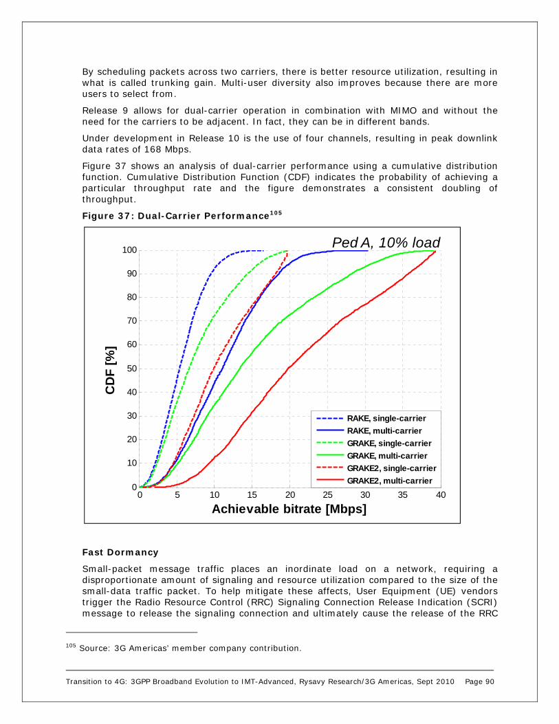
Transition to 4G: 3GPP Broadband Evolution to IMT-Advanced, Rysavy Research/3G Americas, Sept 2010 Page 90
By scheduling packets across two carriers, there is better resource utilization, resulting in what is called trunking gain. Multi-user diversity also improves because there are more users to select from.
Release 9 allows for dual-carrier operation in combination with MIMO and without the need for the carriers to be adjacent. In fact, they can be in different bands.
Under development in Release 10 is the use of four channels, resulting in peak downlink data rates of 168 Mbps.
Figure 37 shows an analysis of dual-carrier performance using a cumulative distribution function. Cumulative Distribution Function (CDF) indicates the probability of achieving a particular throughput rate and the figure demonstrates a consistent doubling of throughput.
Figure 37: Dual-Carrier Performance105
Fast Dormancy
Small-packet message traffic places an inordinate load on a network, requiring a disproportionate amount of signaling and resource utilization compared to the size of the small-data traffic packet. To help mitigate these affects, User Equipment (UE) vendors trigger the Radio Resource Control (RRC) Signaling Connection Release Indication (SCRI) message to release the signaling connection and ultimately cause the release of the RRC
105 Source: 3G Americas’ member company contribution.
0 5 10 15 20 25 30 35 400
10
20
30
40
50
60
70
80
90
100
CD
F [
%]
Achievable bitrate [Mbps]
RAKE, single-carrier
RAKE, multi-carrier
GRAKE, single-carrier
GRAKE, multi-carrier
GRAKE2, single-carrier
GRAKE2, multi-carrier
Ped A, 10% load

Transition to 4G: 3GPP Broadband Evolution to IMT-Advanced, Rysavy Research/3G Americas, Sept 2010 Page 91
connection between the network and UE. This causes the UE to rapidly return to idle mode, which is the most battery-efficient radio state. This is a highly desirable behavior as it greatly increases the battery life of the mobile terminal device whilst freeing up unused radio resource in the network.
If the device implementation for triggering fast dormancy is not done in an appropriate manner, however, then the resulting recurrent signaling procedures needed to re-establish the data connection, as described above, may lead to network overload. In order to overcome this drawback, there was broad industry consensus to standardize the fast dormancy feature in 3GPP Release 8 by providing the network continued control over the UE RRC state transitions.
A cell indicates support for the Release 8 feature via the broadcast of an inhibit timer. The UE supporting the feature, once it has determined it has no more packet-switched data for a prolonged period, sends a SCRI conveying an explicit cause value. The network on receipt of this message controls the resulting state transition to a more battery efficient state, such as CELL_PCH or Utran Registration Area Paging Channel (URA_PCH). In this way, the UE maintains the PS signaling connection and does not require the re-establishment of the RRC connection for a subsequent data transfer. In addition, the network inhibit timer prevents frequently repeated fast dormancy requests from the UE.
Thereby, the feature mitigates the impact on network signaling traffic whilst reducing the latency for any follow-on packet-switched data transmission compared to when the feature is not supported and significantly improves UE battery efficiency.
Field test results have shown fast dormancy improves standby time for a UMTS device by as much as 30% to 40%. The following graph provides an example of the battery life improvement due to fast dormancy for this scenario. It compares two devices running concurrently on a commercial UMTS network with an e-mail sent every 17 minutes. The X-axis represents time, with the right side being how long a battery would last in the absence of fast dormancy.
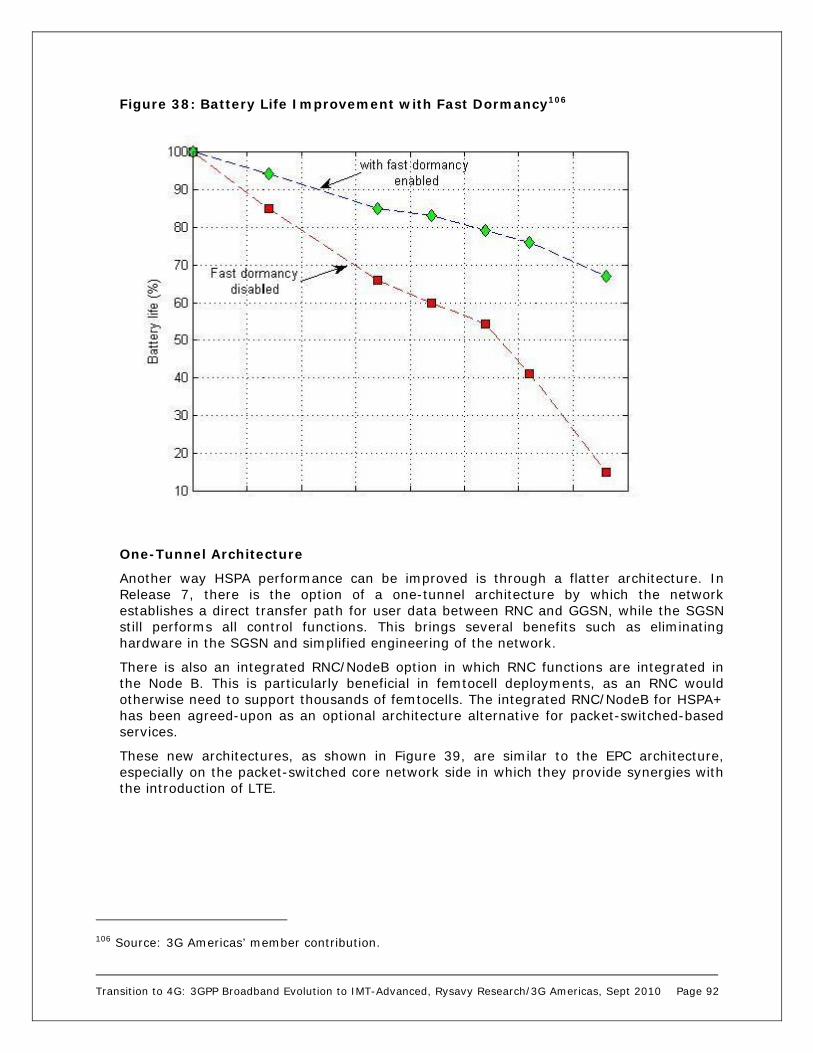
Transition to 4G: 3GPP Broadband Evolution to IMT-Advanced, Rysavy Research/3G Americas, Sept 2010 Page 92
Figure 38: Battery Life Improvement with Fast Dormancy106
One-Tunnel Architecture
Another way HSPA performance can be improved is through a flatter architecture. In Release 7, there is the option of a one-tunnel architecture by which the network establishes a direct transfer path for user data between RNC and GGSN, while the SGSN still performs all control functions. This brings several benefits such as eliminating hardware in the SGSN and simplified engineering of the network.
There is also an integrated RNC/NodeB option in which RNC functions are integrated in the Node B. This is particularly beneficial in femtocell deployments, as an RNC would otherwise need to support thousands of femtocells. The integrated RNC/NodeB for HSPA+ has been agreed-upon as an optional architecture alternative for packet-switched-based services.
These new architectures, as shown in Figure 39, are similar to the EPC architecture, especially on the packet-switched core network side in which they provide synergies with the introduction of LTE.
106 Source: 3G Americas’ member contribution.

Transition to 4G: 3GPP Broadband Evolution to IMT-Advanced, Rysavy Research/3G Americas, Sept 2010 Page 93
Figure 39: HSPA One-Tunnel Architecture107
HSPA, HSPA+, and other advanced functions provide a compelling advantage for UMTS over competing technologies: The ability today to support voice and data services on the same carrier and across the whole available radio spectrum; to offer these services simultaneously to users; to deliver data at ever-increasing broadband rates; and to do so in a spectrally efficient manner.
HS-FACH AND HS-RACH
In Release 7, a new capability called High-Speed Access Forward Access Channel (HS-FACH), illustrated in
107 Source: 3G Americas’ white paper, 2007, “UMTS Evolution from 3GPP Release 7 to Release 8.”
User Plane
Control Plane
Node B
RNC
SGSN
GGSN
Traditional HSPA Architecture
Node B
SGSN
GGSN
Possible HSPA+ with One-Tunnel Architecture
Node B
SGSN
GGSN
HSPA with One-Tunnel Architecture
RNC

Transition to 4G: 3GPP Broadband Evolution to IMT-Advanced, Rysavy Research/3G Americas, Sept 2010 Page 94
Figure 40, reduces setup time to practically zero and provides a more efficient way of carrying application signaling for always-on applications. The network accomplishes this by using the same HSDPA power/code resources for access requests (CELL_FACH state) as for dedicated packet transfer (CELL_DCH). This allows data transmission to start during the HS-FACH state with increased data rates immediately available to the user equipment. During the HS-FACH state, the network allocates dedicated resources for transitioning the user equipment to a dedicated channel state.

Transition to 4G: 3GPP Broadband Evolution to IMT-Advanced, Rysavy Research/3G Americas, Sept 2010 Page 95
Figure 40: High-Speed Forward Access Channel108
HS-RACH
In Release 8, the concept above extends to the uplink by activating the E-DCH in CELL_FACH to reduce the delay before E-DCH can be used. This feature is called High-Speed Reverse Access Channel (HS-RACH), and together with HS-FACH, is referred to as the enhanced CELL_FACH operation.
The RACH is intended for small amounts of data and thus has a limited data rate and can only support transmission of a single transport block. For larger amounts of data, terminals must transmit multiple time on the RACH or transition to the dedicated
108 Source: "LTE for UMTS, OFDMA and SC-FDMA Based Radio Access,” Harri Holma and Antti Toskala, Wiley, 2009.
RACH + FACH
HSDPA + HSUPA HSDPA + HSUPA
R99-R6 solution R7/R8 solution
6-32 kbps >1 Mbps
Seamless transitionDelay >0.5 s
>1 Mbps
Cell_FACH Cell_DCH Cell_FACH Cell_DCH
PCH
FACH
DCH/HSPA
No data flow during transition >500 ms
Cell update and C-RNTI allocation takes >300 ms
RB recon-figuration
RB recon-figuration
PCH
eFACH
HSPA
Data flows on HS-FACH also during transition.
Immediate transmission w/o cell update. No PCH required.
R99-RC RRC States R7/8 RRC States
DCH – Dedicated ChannelFACH – Forward Access ChannelRACH – Reverse Access ChannelPCH – Paging ChannelHS-FACH – High Speed FACHRB – Radio BearerRRC – Radio Resource Control

Transition to 4G: 3GPP Broadband Evolution to IMT-Advanced, Rysavy Research/3G Americas, Sept 2010 Page 96
channel, which causes delays. Overcoming these delays can be done by transmitting data on the E-DCH while still in the CELL_FACH state. Data transmissions can thus continue uninterrupted as the state changes from CELL_FACH to CEL_DCH.109
Figure 41 summarizes the capabilities and benefits of the features being deployed in HSPA+.
Figure 41: Summary of HSPA Functions and Benefits110
HSPA Voice Support Voice support with WCDMA-dedicated channels in UMTS networks is spectrally very efficient. Moreover, current networks support simultaneous voice and data operation. There are, however, reasons to consider alternate approaches including reducing power consumption and being able to support even more users. One approach is called circuit-switched voice over HSPA. The other is VoIP.
Circuit-Switched (CS) Voice over HSPA
HSPA channels employ many optimizations to obtain a high degree of data throughput, which is why it makes sense to use them to carry voice communications. Doing so with VoIP, however, requires not only supporting packetized voice in the radio channel, but also within the infrastructure network. There is an elegant alternative: To packetize the circuit-switched voice traffic which is already in digital form, use the HSPA channels to carry the CS voice, but then to connect the CS voice traffic back into the existing CS infrastructure (MSCs, etc.) immediately beyond the radio access network. This requires
109 Source: “3G Evolution: HSPA and LTE for Mobile Broadband,” E. Dahlman, et al, Elsevier, 2008. 110 Source: 3G Americas’ member contribution.
Uplink DTX + downlink DRX
L2 optimization (Flexible RLC)
High speed FACH + High speed RACH
Downlink 64QAM, MIMO and Dual carrier
CS voice over HSPA
Uplink 16QAM
Lower UE power consumption
Higher voice capacity
Higher L2 throughput and less processing requirements
Lower latency = better response times
More efficient common channels = savings in channel elements
Higher downlink peak data rates and higher data capacity
Higher uplink peak data rates
Flat architecture optimization Less network elements

Transition to 4G: 3GPP Broadband Evolution to IMT-Advanced, Rysavy Research/3G Americas, Sept 2010 Page 97
relatively straightforward changes in just the radio network and in devices. The following figure shows the infrastructure changes required at the Node B and within the RNC.
Figure 42: Implementation of HSPA CS Voice111
With this approach, legacy mobile phones can continue using WCDMA-dedicated traffic channels for voice communications, while new devices use HSPA channels. HSPA CS voice can be deployed with Release 7 or later networks.
The many benefits of this approach, listed below, make it highly likely that operators will adopt it:
Relatively easy to implement and deploy.
Transparent to existing CS infrastructure.
Supports both narrowband and wideband codecs.
Significantly improves battery life with voice communications.
Enables faster call connections.
Provides a 50% to 100% capacity gain over current voice implementations.
Acts as a stepping stone to VoIP over HSPA/LTE in the future.
VoIP
Once HSDPA and HSUPA are available, operators will have another option of moving voice traffic over to these high-speed data channels, which is using VoIP. This will eventually increase voice capacity, allow operators to consolidate their infrastructure on an IP platform, and enable innovative new applications that combine voice with data
111 Source: 3G Americas’ white paper, 2007, “UMTS Evolution from 3GPP Release 7 to Release 8.”
IuCS
IuPS
RNC
CS R99
AMR adapt.
Transportqueues etc
HSPA
PS R99
NodeB
HSPA schedulerCombined
to one carrier
AMR adaptation possible
CS mapped to R99 or HSPA bearer depending on terminal capability
Scheduler prioritizesvoice packets

Transition to 4G: 3GPP Broadband Evolution to IMT-Advanced, Rysavy Research/3G Americas, Sept 2010 Page 98
functions in the packet domain. VoIP is possible in Release 6, but it is enhancements in Release 7 that make it highly efficient and thus attractive to network operators. VoIP will be implemented in conjunction with IMS, discussed later in this paper.
One attractive aspect of deploying VoIP with HSPA is that operators can smoothly migrate users from circuit-switched operation to packet-switched operation over time. Because the UMTS radio channel supports both circuit-switched voice and packet-switched data, some voice users can be on legacy circuit-switched voice and others can be on VoIP. Figure 43 shows a system’s voice capacity with the joint operation of circuit-switched and IP-based voice services.
Figure 43: Ability for UMTS to Support Circuit and Packet Voice Users112
VoIP capacity gains are quantified in detail in the main part of in this paper. They range from 20 % to as high as 100 % with the implementation of interference cancellation and the minimization of IP overhead through a scheme called Robust Header Compression (ROHC).
Whereas packet voice is the only way voice will be supported in LTE, with HSPA+, it may not be used immediately for primary voice services. This is because UMTS already has a highly efficient, circuit-switched voice service and already allows simultaneous voice/data operation. Moreover, packet voice requires a considerable amount of new infrastructure in the core network. As a result, packet voice will likely be used initially as part of other services (for example, those based on IMS), and only over time will it transition to primary voice service.
3GPP LTE Although HSPA and HSPA+ offer a highly efficient broadband-wireless service that will enjoy success for the remainder of this decade and well into the next, 3GPP has completed the specification for Long Term Evolution as part of Release 8. LTE will allow operators to achieve even higher peak throughputs in higher spectrum bandwidth. Work
112 Source: 3G Americas’ member contribution.
0
0.2
0.4
0.6
0.8
1
1.2
1.4
0 2 4 6 8 10 12 14
VoIP
CS
CS + VoIP
Power reserved for PS traffic (W)
Rela
tive C
apac
ity
PS Evolution
0
0.2
0.4
0.6
0.8
1
1.2
1.4
0 2 4 6 8 10 12 14
VoIP
CS
CS + VoIP
Power reserved for PS traffic (W)
Rela
tive C
apac
ity
0
0.2
0.4
0.6
0.8
1
1.2
1.4
0 2 4 6 8 10 12 14
VoIP
CS
CS + VoIP
Power reserved for PS traffic (W)
Rela
tive C
apac
ity
PS Evolution

Transition to 4G: 3GPP Broadband Evolution to IMT-Advanced, Rysavy Research/3G Americas, Sept 2010 Page 99
on LTE began in 2004 with an official work item started in 2006 and a completed specification early 2009. Initial deployments will occur in 2010.
LTE uses OFDMA on the downlink, which is well suited to achieve high peak data rates in high-spectrum bandwidth. WCDMA radio technology is basically as efficient as OFDM for delivering peak data rates of about 10 Mbps in 5 MHz of bandwidth. Achieving peak rates in the 100 Mbps range with wider radio channels, however, would result in highly complex terminals, and it is not practical with current technology. This is where OFDM provides a practical implementation advantage. Scheduling approaches in the frequency domain can also minimize interference, thereby boosting spectral efficiency. The OFDMA approach is also highly fleble in channelization, and LTE will operate in various radio channel sizes ranging from 1.4 to 20 MHz.
On the uplink, however, a pure OFDMA approach results in high Peak to Average Ratio (PAR) of the signal, which compromises power efficiency and, ultimately, battery life. Hence, LTE uses an approach called SC-FDMA, which is somewhat similar to OFDMA, but has a 2 to 6 dB PAR advantage over the OFDMA method used by other technologies such as WiMAX.
LTE capabilities include:
Downlink peak data rates up to 326 Mbps with 20 MHz bandwidth.
Uplink peak data rates up to 86.4 Mbps with 20 MHz bandwidth.
Operation in both TDD and FDD modes.
Scalable bandwidth up to 20 MHz covering 1.4, 3, 5, 10, 15, and 20 MHz in the study phase.
Increased spectral efficiency over Release 6 HSPA by a factor of two to four.
Reduced latency, to 10 msec round-trip times between user equipment and the base station, and to less than 100 msec transition times from inactive to active.
Self-optimizing capabilities under operator control and preferences that will automate network planning and will result in lower operator costs.
LTE Throughput Rates
The overall objective is to provide an extremely high-performance, radio-access technology that offers full vehicular speed mobility and that can readily coexist with HSPA and earlier networks. Because of scalable bandwidth, operators will be able to easily migrate their networks and users from HSPA to LTE over time.
Table 17 shows LTE peak data rates based on different downlink and uplink designs.
Table 17: LTE Peak Throughput Rates
LTE Configuration Downlink (Mbps) Peak Data Rate
Uplink (Mbps) Peak Data Rate
Using 2X2 MIMO in the Downlink and 16 QAM in the Uplink
172.8 57.6
Using 4X4 MIMO in the Downlink and 64 QAM in the Uplink
326.4 86.4

Transition to 4G: 3GPP Broadband Evolution to IMT-Advanced, Rysavy Research/3G Americas, Sept 2010 Page 100
LTE is not only efficient for data but, because of a highly efficient uplink, is extremely efficient for VoIP traffic. In 10 MHz of spectrum, LTE VoIP capacity will reach almost 500 users.113
OFDMA and Scheduling
LTE implements OFDM in the downlink. The basic principle of OFDM is to split a high-rate data stream into a number of parallel, low-rate data streams, each a narrowband signal carried by a subcarrier. The different narrowband streams are generated in the frequency domain, and then combined to form the broadband stream using a mathematical algorithm called an Inverse Fast Fourier Transform (IFFT) that is implemented in digital-signal processors. In LTE, the subcarriers have 15 kHz spacing from each other. LTE maintains this spacing regardless of the overall channel bandwidth, which simplifies radio design, especially in supporting radio channels of different widths. The number of subcarriers ranges from 72 in a 1.4 MHz channel to 1,200 in a 20 MHz channel.
The composite signal is obtained after the IFFT is extended by repeating the initial part of the signal (called the Cyclic Prefix [CP]). This extended signal represents an OFDM symbol. The CP is basically a guard time during which reflected signals will reach the receiver. It results in an almost complete elimination of multipath-induced Intersymbol Interference (ISI), which otherwise makes extremely high data-rate transmissions problematic. The system is called orthogonal, because the subcarriers are generated in the frequency domain (making them inherently orthogonal), and the IFFT conserves that characteristic. OFDM systems may lose their orthogonal nature as a result of the Doppler shift induced by the speed of the transmitter or the receiver. 3GPP specifically selected the subcarrier spacing of 15 kHz to avoid any performance degradation in high-speed conditions. WiMAX systems that use a lower subcarrier spacing (~11 kHz) will be more impacted in high-speed conditions than LTE.
Figure 44: OFDM Symbol with Cyclic Prefix
The multiple-access aspect of OFDMA comes from being able to assign different users different subcarriers over time. A minimum resource block that the system can assign to a user transmission consists of 12 subcarriers over 14 symbols in 1.0 msec. Figure 45 shows how the system can assign these resource blocks to different users over both time and frequency.
113 Source: 3GPP Multi-member analysis.
Cyclic Prefix(4.8 sec)
Data(66.7 sec)

Transition to 4G: 3GPP Broadband Evolution to IMT-Advanced, Rysavy Research/3G Americas, Sept 2010 Page 101
Figure 45: LTE OFDMA Downlink Resource Assignment in Time and Frequency
By having control over which subcarriers are assigned in which sectors, LTE can easily control frequency reuse. By using all the subcarriers in each sector, the system would operate at a frequency reuse of 1; but by using a different one third of the subcarriers in each sector, the system achieves a looser frequency reuse of 1/3. The looser frequency reduces overall spectral efficiency, but delivers high peak rates to users.
Beyond controlling frequency reuse, frequency domain scheduling, as shown in Figure 46 can use those resource blocks that are not faded, something that is not possible in CDMA-based systems. Since different frequencies may fade differently for different users, the system can allocate those frequencies for each user that result in the greatest throughput. This results in up to a 40% gain in average cell throughput for low user speed (3 km/hour), assuming a large number of users and no MIMO. The benefit decreases at higher user speeds.
Time
Fre
quen
cyUser 1
User 2
User 3
User 4
Minimum resource block consists of 14 symbols and 12 subcarriers

Transition to 4G: 3GPP Broadband Evolution to IMT-Advanced, Rysavy Research/3G Americas, Sept 2010 Page 102
Figure 46: Frequency-Domain Scheduling in LTE114
Antenna Configurations
LTE in Release 8 provides for multiple types of antenna transmission modes, as shown in Table 18.
Table 18: LTE Transmission Modes115
Transmission Mode Description
1 Single-antenna port
2 Transmit diversity
3 Large-delay, cyclic-delay diversity (open-loop spatial multiplexing)
4 Closed-loop spatial multiplexing
5 Multi-user MIMO
6 Closed-loop single-layer precoding
7 Single-antenna port
Being able to exploit different antenna modes based on conditions produces huge efficiency and performance gains, and is the reason that yet more advanced antenna
114 3G Americas’ member contribution. 115 Source: “Field Trials of LTE with 4×4 MIMO,” Ericsson Review No. 1, 2010.
Frequency
Resource block
Transmit on those resource blocks that are not faded
Carrier bandwidth
Transition to 4G: 3GPP Broadband Evolution to IMT-Advanced, Rysavy Research/3G Americas, Sept 2010 Page 103
modes are being developed for subsequent releases of LTE. There are some fundamental variables that distinguish the different antenna modes.
Single base-station antenna versus multiple antennas. Single antennas provide for Single Input Single Output (SISO), Single Input Multiple Output (SIMO) and planar-array beamforming. (Multiple Output means the UE has multiple antennas.) Multiple antennas at the base station provide for different MIMO modes such as 2X2, 4X2, and 4X4.
Single-user MIMO versus multi-user MIMO. Release 8 only provides for single-user MIMO on the downlink. Release 10 includes multi-user MIMO.
Open Loop versus Closed Loop. High vehicular speeds require open-loop operation whereas slow speeds enabled closed-loop operation in which feedback from the UE modifies the transmission.
Rank. In a MIMO system, the channel rank is formally defined as the rank of the channel matrix and is a measure of the degree of scattering that the channel exhibits. For example, in a 2x2 MIMO system, a rank of one indicates a low-scattering environment, while a rank of two indicates a high-scattering environment. The rank two channel is highly uncorrelated, and is thus able to support the spatial multiplexing of two data streams, while a rank one channel is highly correlated, and thus can only support single stream transmission (the resulting multi-stream interference in a rank one channel as seen at the receiver would lead to degraded performance). Higher Signal to Interference plus Noise Ratios (SINR) are typically required to support spatial multiplexing, while lower SINRs are typically sufficient for single stream transmission. In a 4x4 MIMO system channel rank values of three and four are possible in addition to values of one and two. The number of data streams, however, or more specifically codewords in LTE is limited to a value of two. Thus, LTE has defined the concept of layers, in which the DL transmitter includes a codeword-to-layer mapping, and in which the number of layers is equal to the channel rank. An antenna mapping or precoding operation follows, which maps the layers to the antenna ports. A 4x2 MIMO system is also possible with LTE Release 8, but here the channel rank is limited to the number of UE antennas, which is equal to two.
The network can dynamically choose between different modes based on instantaneous radio conditions between the base station and the UE. Figure 47 shows the decision tree. The antenna configuration (AC) values refer to the transmission modes. Not every network will support every mode. Operators will choose which modes are the most effective and economical. AC2, 3, 4, and 6 are typical modes that will be implemented.

Transition to 4G: 3GPP Broadband Evolution to IMT-Advanced, Rysavy Research/3G Americas, Sept 2010 Page 104
Figure 47: Decision Tree for Different Antenna Schemes116
The simplest mode is AC2, which is referred to as Transmit Diversity (TD) or sometimes Space Frequency Block Code (SFBC) or even Open Loop Transmit Diversity. TD can be supported under all conditions, meaning it can operate under low SINR, high mobility, and low channel rank (rank = 1). This rank means that the channel is not sufficiently scattered or de-correlated to support two spatial streams. Thus, in TD, only one spatial stream or what is sometimes referred as a single codeword (SCW) is transmitted. If the channel rank increases to a value of two, indicating a more scattered channel, and the SINR is a bit higher, then the system can adapt to AC3 or Open-Loop Spatial Multiplexing (OL-SM), which is also referred to as large-delay Cyclic Delay Diversity (CDD). This mode supports two spatial streams or two codewords. This mode, also referred to as multiple codeword (MCW) operation, increases throughput over SCW transmission.
If the rank of the channel is one, but the device is not moving very fast or is stationary, then the system can adapt to AC6, called closed-loop (CL) precoding (or CL-rank 1 or CL-R1). In this mode, feedback is provided by the device in terms of Precoding Matrix Indication (PMI) bits. These tell the base station what precoding matrix to use in the transmitter so as to optimize link performance. This feedback is only relevant for low-mobility or stationary conditions since in high mobility conditions the feedback will most likely be outdated by the time it can be used by the base station.
Another mode is AC4 or Closed Loop Spatial Multiplexing (CL-SM), which is enabled for low mobility, high SINR, and channel rank of two. This mode theoretically provides the best user throughput. The figure above shows how these modes can adapt downwards to either OL TD, or if in CL-SM mode, down to either OL TD or CL R1.
For a 4x4 MIMO configuration, the channel rank can take on values of three and four in addition to one or two. Initial deployment at the base station, however, will likely be two
116 Source: 3G Americas’ white paper “MIMO and Smart Antennas for 3G and 4G Wireless Systems – Practical Aspects and Deployment Considerations,” May 2010.

Transition to 4G: 3GPP Broadband Evolution to IMT-Advanced, Rysavy Research/3G Americas, Sept 2010 Page 105
TX antennas and most devices will only have 2 RX antennas, and thus the rank is limited to 2.
AC5 is MU-MIMO, which is not defined for the downlink in Release 8.
AC1 and AC7 are single antenna port modes in which AC1 uses a common Reference Signal (RS), while AC7 uses a dedicated RS or what is also called a user specific RS. AC1 implies a single TX antenna at the base station. AC7 implies an antenna array with antennal elements closely spaced so that a physical or spatial beam can be formed towards an intended user.
LTE is specified for a variety of MIMO configurations. On the downlink, these include 2X2, 4X2 (four antennas at the base station), and 4X4. Initial deployment will likely be 2x2. 4X4 will be most likely used initially in femtocells. On the uplink, there are two possible approaches: single-user MIMO (SU-MIMO) and multi-user MIMO (MU-MIMO). SU-MIMO is more complex to implement as it requires two parallel radio transmit chains in the mobile device, whereas MU-MIMO does not require any additional implementation at the device. The first LTE release thus incorporates MU-MIMO with SU-MIMO deferred for the second LTE release.
Peak data rates are approximately proportional to the number of send and receive antennas. 4X4 MIMO is thus theoretically capable of twice the data rate of a 2X2 MIMO system. The spatial-multiplexing MIMO modes that support the highest throughput rates will be available in early deployments.
For a more detailed discussion of 3GPP antenna technologies, refer to the 3G Americas’ white paper “MIMO and Smart Antennas for 3G and 4G Wireless Systems – Practical Aspects and Deployment Considerations,” May 2010.
Channel Bandwidths
LTE is designed to operate in channel bandwidths from 1.4 MHz to 20 MHz. The greatest efficiency, however, occurs with higher bandwidth. A 3G Americas’ member analysis predicts 40% lower spectral efficiency with 1.4 MHz radio channels and 13% lower efficiency with 3 MHz channels.117 The system, however, achieves nearly all of its efficiency with 5 MHz channels or wider.
IPv4/IPv6
Release 8 defines support for IPv6 for both LTE and UMTS networks. An Evolved Packet System bearer can carry both IPv4 and IPv6 traffic. This enables a UE to communicate both IPv4 and IPv6 packets (assuming it has a dual stack) while connected through a single EPS bearer. It is up to the operator, however, whether it assigns IPv4, IPv6, or both types of addresses to UE.
Communicating between IPv6-only devices and IPv4 end-points will require protocol-conversion or proxies. For further details, refer to the 3G Americas’ white paper, “IPv6 – Transition Considerations for LTE and Evolved Packet Core,” February 2009.
Voice Support
Voice support in LTE will range from no voice, to voice implemented in a circuit-switched fallback (CSFB) mode to 2G or 3G, to voice implemented over LTE using IMS.
As a pure data service, especially for laptops, voice may not be needed. But once available on handheld devices, voice will become important. The easiest implementation
117 3G Americas’ member company analysis 2009.

Transition to 4G: 3GPP Broadband Evolution to IMT-Advanced, Rysavy Research/3G Americas, Sept 2010 Page 106
will be CSFB. In CSFB, the LTE network carries circuit-switched signaling over LTE interfaces. This allows the subscriber to be registered with the 2G/3G MSC even while on the LTE network. When there is a CS-event, such as an incoming voice call, the MSC sends the page to the LTE core network which delivers it to the subscriber device. The device then switches to 2G/3G operation to answer the call.
Voice over LTE will operate as VoIP and requires IMS infrastructure. To facilitate IMS-based voice, vendors and operators created the One Voice initiative to define required baseline functionality for user equipment, the LTE access network, the Evolved Packet Core, and for the IMS. Terminals and networks implementing these capabilities could become available in the 2012 timeframe. GSMA has adopted the One Voice initiative in what it calls Voice over LTE (VoLTE) and is working to enable interconnection and international roaming between LTE networks with work scheduled to be completed by Q1 of 2011.
LTE VoIP will leverage the QoS capabilities defined for EPC, which specify different quality classes.
Single-Radio Voice Call Continuity (SR-VCC) will allow user equipment in midcall to switch to a circuit-switched network in the event that it moves out of LTE coverage. Similarly, data sessions can be handed over in what is called Packet Switched Handover (PSHO).
Figure 48 shows how an LTE network might evolve in three stages. Initially, LTE performs only data service, and the underlying 2G/3G network provides voice service via CSFB. In the second stage, voice over LTE is available, but LTE covers only a portion of the total 2G/3G coverage area. Hence, voice in 2G/3G can occur via CSFB or SR-VCC. Eventually, LTE coverage will match 2G/3G coverage, and LTE devices will use only the LTE network.

Transition to 4G: 3GPP Broadband Evolution to IMT-Advanced, Rysavy Research/3G Americas, Sept 2010 Page 107
Figure 48: Evolution of Voice in an LTE Network118
There is yet one other voice approach called Voice over LTE via Generic Access (VoLGA). This method provides for circuit-switched operation through an LTE IP tunnel. 3GPP has stopped official standards work that would support VoLGA and ongoing work is being handled by the VoLGA Forum.
TDD Harmonization
3GPP developed LTE TDD to be fully harmonized with LTE FDD including alignment of frame structures, identical symbol-level numerology, the possibility of using similar reference signal patterns, and similar synchronization and control channels. Also, there is only one TDD variant. Furthermore, LTE TDD has been designed to co-exist with TD-SCDMA and TD-CDMA/UTRA (both low-chip rate and high-chip rate versions). LTE TDD achieves compatibility and co-existence with TD-SCDMA by defining frame structures where the DL and UL time periods can be time aligned to prevent BTS to BTS and UE to UE interference to support operation in adjacent carriers without the need for large guardbands between the technologies. This will simplify deployment of LTE TDD in countries such as China that are deploying TD-SCDMA. Figure 49 demonstrates the synchronization between TC-SCDMA and LTE-TDD in adjacent channels.
118 Source: 3G Americas’ member contribution.
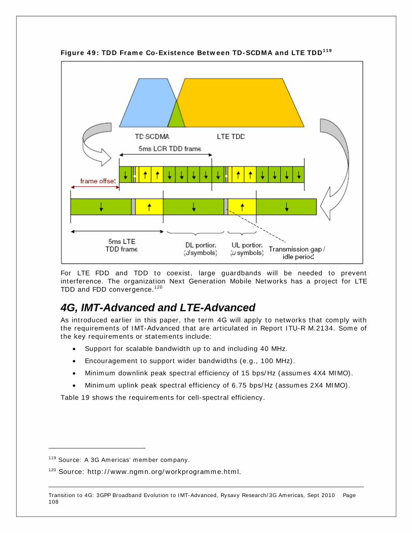
Transition to 4G: 3GPP Broadband Evolution to IMT-Advanced, Rysavy Research/3G Americas, Sept 2010 Page 108
Figure 49: TDD Frame Co-Existence Between TD-SCDMA and LTE TDD119
For LTE FDD and TDD to coexist, large guardbands will be needed to prevent interference. The organization Next Generation Mobile Networks has a project for LTE TDD and FDD convergence.120
4G, IMT-Advanced and LTE-Advanced As introduced earlier in this paper, the term 4G will apply to networks that comply with the requirements of IMT-Advanced that are articulated in Report ITU-R M.2134. Some of the key requirements or statements include:
Support for scalable bandwidth up to and including 40 MHz.
Encouragement to support wider bandwidths (e.g., 100 MHz).
Minimum downlink peak spectral efficiency of 15 bps/Hz (assumes 4X4 MIMO).
Minimum uplink peak spectral efficiency of 6.75 bps/Hz (assumes 2X4 MIMO).
Table 19 shows the requirements for cell-spectral efficiency.
119 Source: A 3G Americas’ member company. 120 Source: http://www.ngmn.org/workprogramme.html.

Transition to 4G: 3GPP Broadband Evolution to IMT-Advanced, Rysavy Research/3G Americas, Sept 2010 Page 109
Table 19: IMT-Advanced Requirements for Cell-Spectral Efficiency
Test Environment121 Downlink (bps/Hz) Uplink (bps/Hz)
Indoor 3.0 2.25
Microcellular 2.6 1.8
Base Coverage Urban 2.2 1.4
High Speed 1.1 0.7
Table 20 shows the requirements for voice capacity.
Table 20: IMT-Advanced Requirements for Voice Capacity
Test Environment122 Minimum VoIP Capacity (Active Users/Sector/MHz)
Indoor 50
Microcellular 40
Base Coverage Urban 40
High Speed 30
3GPP is addressing the IMT-Advanced requirements through a version of LTE called LTE-Advanced, a project that is a study item in 2009 with specifications expected in the second half of 2010 as part of Release 10. LTE-Advanced will be both backwards- and forwards-compatible with LTE, meaning LTE devices will operate in newer LTE-Advanced networks, and LTE-Advanced devices will operate in older LTE networks.
3GPP is studying the following capabilities for LTE-Advanced:
Wider bandwidth support for up to 100 MHz via aggregation of 20 MHz blocks.
Uplink MIMO (two transmit antennas in the device).
Downlink MIMO of up to 8 by 8 as described below.
Coordinated multipoint transmission (CoMP) with two proposed approaches: coordinated scheduling and/or beamforming, and joint processing/transmission. The intent is to closely coordinate transmissions at different cell sites, thereby achieving higher system capacity and improving cell-edge data rates.123
121 Test environments are described in IT Report ITU-R M.2135. 122 Ibid. 123 For further details, refer to section 7.7.5 of the 3G Americas’ white paper “The Mobile Broadband Evolution: 3G Release 8 and Beyond, HSPA+, SAE/LTE and LTE-Advanced.”

Transition to 4G: 3GPP Broadband Evolution to IMT-Advanced, Rysavy Research/3G Americas, Sept 2010 Page 110
Figure 50 shows the carrier aggregation, with up to 100 MHz of bandwidth supported.
Figure 50: Release 10 LTE-Advanced Carrier Aggregation124
Figure 51 shows the carrier aggregation operating at different protocol layers.
Figure 51: Carrier Aggregation at Different Protocol Layers125
Some specific carrier aggregation schemes being proposed include:
FDD: UL of 40 MHz, DL of 40 MHz in band 7 (2600 MHz)
124 Source: "LTE for UMTS, OFDMA and SC-FDMA Based Radio Access,” Harri Holma and Antti Toskala, Wiley, 2009. 125 Source: “The Evolution of LTE towards IMT-Advanced”, Stefan Parkvall and David Astely, Ericsson Research, http://www.academypublisher.com/jcm/vol04/no03/jcm0403146154.pdf
Rel’8
100 MHz bandwidth
Rel’8 Rel’8 Rel’8 Rel’8
Release 10 LTE-Advanced UE resource pool
Release 8 UE uses a single 20 MHz block
20 MHz

Transition to 4G: 3GPP Broadband Evolution to IMT-Advanced, Rysavy Research/3G Americas, Sept 2010 Page 111
TDD: UL/DL of 50 MHz in band 40 (2300 MHz)
TDD: UL/DL of 40 MHz in band 38 (2600 MHz)126
Beyond wider bandwidths, LTE-Advanced will extend performance through more powerful multi-antenna capabilities. For the downlink, the technology will be able to transmit in up to eight layers using an 8X8 configuration for a peak spectral efficiency of 30 bps/Hz that exceeds the IMT-Advanced requirements, conceivably supporting a peak rate of 1 Gbps in just 40 MHz and even higher rates in wider bandwidths. This would require additional reference signals for channel estimation and for measurements such as channel quality to enable adaptive, multi-antenna transmission. LTE-Advanced will also include four-layer transmission in the uplink resulting in spectral efficiency exceeding 15 bps/Hz.
Table 21 shows anticipated performance relative to IMT-Advanced Requirements.
Table 21: IMT-Advanced Requirements and Anticipated LTE-Advanced Capability.
Item IMT-Advanced Requirement
LTE-Advanced Projected Capability
Peak Data Rate Downlink 1 Gbps
Peak Data Rate Uplink 500 Mbps
Spectrum Allocation Up to 40 MHz Up to 100 MHz
Latency User Plane 10 msec 10 msec
Latency Control Plane 100 msec 50 msec
Peak Spectral Efficiency DL127 15 bps/Hz 30 bps/Hz
Peak Spectral Efficiency UL 6.75 bps/Hz 15 bps/Hz
Average Spectral Efficiency DL 2.2 bps/Hz 2.6 bps/Hz
Average Spectral Efficiency UL 1.4 bps/Hz 2.0 bps/Hz
Cell-Edge Spectral Efficiency DL 0.06 bps/Hz 0.09 bps/Hz
Cell-Edge Spectral Efficiency UL 0.03 bps/Hz 0.07 bps/Hz
In all cases, projections of LTE-Advanced performance exceed that of the IMT-Advanced requirements.
Another capability being planned for LTE-Advanced is relays as shown in Figure 52. The idea is to relay frames at an intermediate node, resulting in much better in-building penetration, and with better signal quality, user rates will be much improved. Relays provide a means for lowering deployment costs in initial deployments in which usage is relatively low. As usage increases and spectrum needs to be allocated to access only, operators can then employ alternate backhaul schemes.
126 3GPP TSG-RAN WG4 Meeting #54, R4-101062, “LTE-A Deployment Scenarios.” 127 Spectral efficiency values based on four antennas at the base station and two antennas at the terminal.

Transition to 4G: 3GPP Broadband Evolution to IMT-Advanced, Rysavy Research/3G Americas, Sept 2010 Page 112
Figure 52: LTE-Advanced Relay128
As demonstrated in this section, LTE-Advanced will have tremendous capability. Although initial deployments of LTE will be based on Release 8, as new spectrum becomes available in the next decade, especially if it includes wide radio channels, then LTE-Advanced will be the ideal technology for these new bands. Even in existing bands, operators are likely to eventually upgrade their LTE networks to LTE-Advanced to obtain spectral efficiency gains and capabilities such as relaying.
UMTS TDD Most WCDMA and HSDPA deployments are based on FDD, in which the operator uses different radio bands for transmit and receive. An alternate approach is TDD, in which both transmit and receive functions alternate in time on the same radio channel. 3GPP specifications include a TDD version of UMTS, called UMTS TDD.
TDD does not provide any inherent advantage for voice functions, which need balanced links—namely, the same amount of capacity in both the uplink and the downlink. Many data applications, however, are asymmetric, often with the downlink consuming more bandwidth than the uplink, especially for applications like Web browsing or multimedia downloads. A TDD radio interface can dynamically adjust the downlink-to-uplink ratio accordingly, hence balancing both forward-link and reverse-link capacity. Note that for UMTS FDD, the higher spectral efficiency achievable in the downlink versus the uplink is critical in addressing the asymmetrical nature of most data traffic.
The UMTS TDD specification also includes the capability to use joint detection in receiver-signal processing, which offers improved performance.
One consideration, however, relates to available spectrum. Various countries around the world including those in Europe, Asia, and the Pacific region have licensed spectrum available specifically for TDD systems. For this spectrum, UMTS TDD or, in the future, LTE in TDD mode is a good choice. It is also a good choice in any spectrum that does not provide a duplex gap between forward and reverse links.
In the United States, there is limited spectrum specifically allocated for TDD systems.129 UMTS TDD is not a good choice in FDD bands; it would not be able to operate effectively in both bands, thereby making the overall system efficiency relatively poor.
128 Source: 3G Americas’ member contribution.
Relay Link Access Link
Direct Link
Transition to 4G: 3GPP Broadband Evolution to IMT-Advanced, Rysavy Research/3G Americas, Sept 2010 Page 113
As discussed in more detail in the “WiMAX” section, TDD systems require network synchronization and careful coordination between operators or guardbands, which may be problematic in certain bands.
There has been little deployment of UMTS TDD. Future TDD deployments of 3GPP technologies are likely to be based on LTE.
TD-SCDMA TD-SCDMA is one of the official 3G wireless technologies being developed, mostly for deployment in China. Specified through 3GPP as a variant of the UMTS TDD System and operating with a 1.28 megachips per second (Mcps) chip rate against 3.84 Mcps for UMTS TDD, the primary attribute of TD-SCDMA is that it is designed to support very high subscriber densities. This makes it a possible alternative for wireless local loops. TD-SCDMA uses the same core network as UMTS, and it is possible for the same core network to support both UMTS and TD-SCDMA radio-access networks.
TD-SCDMA technology is not as mature as UMTS and CDMA2000, with 2008 being the first year of limited deployments in China in time for the Olympic Games. Although there are no planned deployments in any country other than China, TD-SCDMA could theoretically be deployed anywhere unpaired spectrum is available—such as the bands licensed for UMTS TDD—assuming appropriate resolution of regulatory issues.
IMS IMS is a service platform that allows operators to support IP multimedia applications. Potential applications include video sharing, PoC, VoIP, streaming video, interactive gaming, and so forth. IMS by itself does not provide all these applications. Rather, it provides a framework of application servers, subscriber databases, and gateways to make them possible. The exact services will depend on cellular operators and the application developers that make these applications available to operators.
The core networking protocol used within IMS is Session Initiation Protocol (SIP), which includes the companion Session Description Protocol (SDP) used to convey configuration information such as supported voice codecs. Other protocols include Real Time Transport Protocol (RTP) and Real Time Streaming Protocol (RTSP) for transporting actual sessions. The QoS mechanisms in UMTS will be an important component of some IMS applications.
Although originally specified by 3GPP, numerous other organizations around the world are supporting IMS. These include the Internet Engineering Taskforce (IETF), which specifies key protocols such as SIP, and the Open Mobile Alliance, which specifies end-to-end, service-layer applications. Other organizations supporting IMS include the GSMA, the ETSI, CableLabs, 3GPP2, The Parlay Group, the ITU, ANSI, the Telecoms and Internet Converged Services and Protocols for Advanced Networks (TISPAN), and the Java Community Process (JCP).
IMS is relatively independent of the radio-access network and can, and likely will, be used by other radio-access networks or wireline networks. Other applications include picture and video sharing that occur in parallel with voice communications. Operators looking to roll out VoIP over networks could also use IMS. 3GPP initially introduced IMS in Release 5 and has enhanced it in each subsequent specification release.
As shown in Figure 53, IMS operates just outside the packet core.
129 The 1910-1920 MHz band targeted unlicensed TDD systems, but has never been used.

Transition to 4G: 3GPP Broadband Evolution to IMT-Advanced, Rysavy Research/3G Americas, Sept 2010 Page 114
Figure 53: IP Multimedia Subsystem
The benefits of using IMS include handling all communication in the packet domain, tighter integration with the Internet, and a lower cost infrastructure that is based on IP building blocks used for both voice and data services. This allows operators to potentially deliver data and voice services at lower cost, thus providing these services at lower prices and further driving demand and usage.
IMS applications can reside either in the operator’s network or in third-party networks including those of enterprises. By managing services and applications centrally—and independently of the access network—IMS can enable network convergence. This allows operators to offer common services across 3G, Wi-Fi, and wireline networks.
IMS is one of the most likely means that operators will use to provide voice service in LTE networks. Service Continuity, defined in Release 8, provides for a user’s entire session to continue seamlessly as the user moves from one access network to another. Release 9 expands this concept to allow sessions to move across different device types. For example, the user could transfer a video call in midsession from a mobile phone to a large-screen TV, assuming both have an IMS appearance in the network.
Release 8 introduces the IMS Centralized Services (ICS) feature, which allows for IMS-controlled voice features to use either packet-switched or circuit-switched access.
Heterogeneous Networks and Self Optimization A fundamental concept in the evolution of next-generation networks is that they will be a blend of multiple types of networks: a network of networks. These networks will be characterized by:
Variations in coverage areas including femtocells, picocells (also referred to as metro cells), and macro cells. Cell range can vary from 10 meters to 50 kilometers.
Different frequency bands.
Call Session Control Function (CSCF)(SIP Proxy)
Home Subscriber Server (HSS)
SIP Application Server
SIP
DIAMETER
IMS
UMTS/HSPAPacket Core
Network
Media ResourceFunction Control
Media ResourceGateway Control
Wi-FiDSL
Multiple Possible Access Networks

Transition to 4G: 3GPP Broadband Evolution to IMT-Advanced, Rysavy Research/3G Americas, Sept 2010 Page 115
Different technologies spanning Wi-Fi, 2G, 3G, and eventually 4G.
Relaying capability where wireless links can serve as backhaul.
Significant challenges must be addressed in these heterogeneous networks. One is near-far effects, where local small-cell signals can easily interfere with macro cells.
As the number of base stations increase through denser deployments and through deployment of femtocells and picocells, manual configuration and maintenance of this infrastructure becomes impractical. 3GPP in TR36.902 addresses the issue of Self-Organizing or Self-Optimizing Networks (SONs) for LTE. With SON, base stations organize and configure themselves by communicating with each other and with the core network. SONs can also self heal in failure situations.
Self-configuration is primarily for handling simplified insertion of new eNB (base station) elements. Self optimization includes automatic management of features such as:
Load balancing between eNBs
Handover parameter determination
Static and dynamic interference control
Management of capacity and coverage
Release 8 includes SON features that are enhanced in subsequent versions of specifications. For example, release 9 adds coverage and capacity optimization and load-balancing optimization. Figure 54 shows how different types of user equipment might access different network layers.
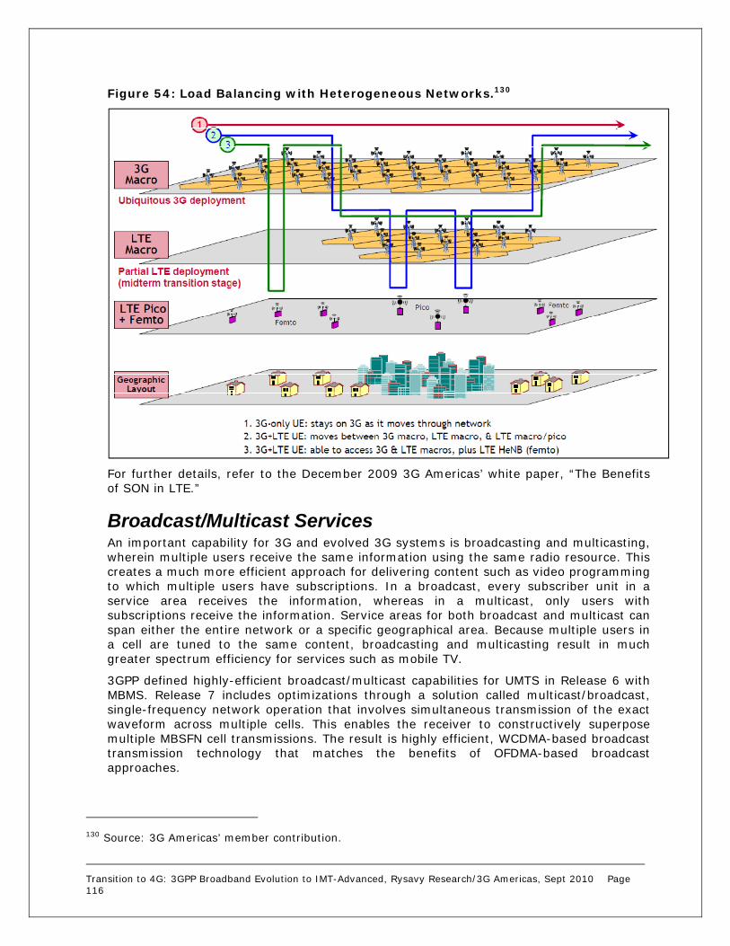
Transition to 4G: 3GPP Broadband Evolution to IMT-Advanced, Rysavy Research/3G Americas, Sept 2010 Page 116
Figure 54: Load Balancing with Heterogeneous Networks.130
For further details, refer to the December 2009 3G Americas’ white paper, “The Benefits of SON in LTE.”
Broadcast/Multicast Services An important capability for 3G and evolved 3G systems is broadcasting and multicasting, wherein multiple users receive the same information using the same radio resource. This creates a much more efficient approach for delivering content such as video programming to which multiple users have subscriptions. In a broadcast, every subscriber unit in a service area receives the information, whereas in a multicast, only users with subscriptions receive the information. Service areas for both broadcast and multicast can span either the entire network or a specific geographical area. Because multiple users in a cell are tuned to the same content, broadcasting and multicasting result in much greater spectrum efficiency for services such as mobile TV.
3GPP defined highly-efficient broadcast/multicast capabilities for UMTS in Release 6 with MBMS. Release 7 includes optimizations through a solution called multicast/broadcast, single-frequency network operation that involves simultaneous transmission of the exact waveform across multiple cells. This enables the receiver to constructively superpose multiple MBSFN cell transmissions. The result is highly efficient, WCDMA-based broadcast transmission technology that matches the benefits of OFDMA-based broadcast approaches.
130 Source: 3G Americas’ member contribution.

Transition to 4G: 3GPP Broadband Evolution to IMT-Advanced, Rysavy Research/3G Americas, Sept 2010 Page 117
LTE will also have a broadcast/multicast capability. OFDM is particularly well-suited for broadcasting, because the mobile system can combine the signal from multiple base stations, and because of the narrowband nature of OFDM. Normally, these signals would interfere with each other. As such, the LTE broadcast capability is expected to be quite efficient.
Figure 55: OFDM Enables Efficient Broadcasting
An alternate approach for mobile TV is to use an entirely separate broadcast network with technologies such as Digital Video Broadcasting–Handheld (DVB-H) or Media Forward Link Only (MediaFLO), which various operators around the world have opted to do. Although this requires a separate radio in the mobile device, the networks are highly optimized for broadcast.
Despite various broadcast technologies being available, market adoption has been relatively slow. Internet trends favor unicast approaches, with users viewing videos of their selection on demand.
EPC 3GPP is defining EPC in Release 8 as a framework for an evolution or migration of the 3GPP system to a higher-data-rate, lower-latency, packet-optimized system that supports multiple radio-access technologies. The focus of this work is on the packet-switched domain with the assumption that the system will support all services—including voice—in this domain.
Although it will most likely be deployed in conjunction with LTE, EPC could also be deployed for use with HSPA+ wherein it could provide a stepping-stone to LTE. EPC will be optimized for all services to be delivered via IP in a manner that is as efficient as possible—through minimization of latency within the system, for example. It will support service continuity across heterogeneous networks, which will be important for LTE operators who must simultaneously support GSM-HSPA customers.
One important performance aspect of EPC is a flatter architecture. For packet flow, EPC includes two network elements, called Evolved Node B (eNodeB) and the Access Gateway (AGW). The eNodeB (base station) integrates the functions traditionally performed by the

Transition to 4G: 3GPP Broadband Evolution to IMT-Advanced, Rysavy Research/3G Americas, Sept 2010 Page 118
radio-network controller, which previously was a separate node controlling multiple Node Bs. Meanwhile, the AGW integrates the functions traditionally performed by the SGSN and GGSN. The AGW has both control functions, handled through the Mobile Management Entity (MME), and user plane (data communications) functions. The user plane functions consist of two elements: A serving gateway that addresses 3GPP mobility and terminates eNodeB connections, and a Packet Data Network (PDN) gateway that addresses service requirements and also terminates access by non-3GPP networks. The MME serving gateway and PDN gateways can be collocated in the same physical node or distributed, based on vendor implementations and deployment scenarios.
The EPC architecture is similar to the HSPA One-Tunnel Architecture discussed in the “HSPA+” section that allows for easy integration of HSPA networks to the EPC. Another architectural option is to reverse the topology, so that the EPC Access Gateway is located close to the RAN in a distributed fashion to reduce latency, while the MME is centrally located to minimize complexity and cost.
EPC also allows integration of non-3GPP networks such as WiMAX. EPC will use IMS as a component. It will also manage QoS across the whole system, which will be essential for enabling a rich set of multimedia-based services.
Figure 56 shows the EPC architecture.
Figure 56: EPC Architecture
Elements of the EPC architecture include:
MME
GERAN
UTRAN
Rel’7 Legacy GSM/UMTS
SGSN
Evolved RAN,e.g., LTE
ServingGateway
PDNGateway
Non 3GPPIP Access
PCRF
IPServices,
IMS
EPC/SAE Access Gateway
Control
User Plane
One-TunnelOption

Transition to 4G: 3GPP Broadband Evolution to IMT-Advanced, Rysavy Research/3G Americas, Sept 2010 Page 119
Support for legacy GERAN and UTRAN networks connected via SGSN.
Support for new radio-access networks such as LTE.
The Serving Gateway that terminates the interface toward the 3GPP radio-access networks.
The PDN gateway that controls IP data services, does routing, allocates IP addresses, enforces policy, and provides access for non-3GPP access networks.
The MME that supports user equipment context and identity, as well as authenticating and authorizing users.
The Policy Control and Charging Rules Function (PCRF) that manages QoS aspects.
3GPP is planning to support voice in EPS through VoIP and IMS. However, there is an alternative voice approach being discussed in the industry, namely transporting circuit-switched voice over LTE, called VOLGA. This approach is not currently part of any 3GPP specifications.
The need for supporting a broader variety of applications requiring higher bandwidth and lower latency led 3GPP to alleviate the existing (UMTS Release 99) QoS principles with the introduction for EPS of a QoS Class Identifier (QCI). The QCI is a scalar denoting a set of transport characteristics (bearer with/without guaranteed bit rate, priority, packet delay budget, packet error loss rate) and used to infer nodes specific parameters that control packet forwarding treatment (e.g., scheduling weights, admission thresholds, queue management thresholds, link-layer protocol configuration, etc.). Each packet flow is mapped to a single QCI value (nine are defined in the Release 8 version of the specifications) according to the level of service required by the application. The usage of the QCI avoids the transmission of a full set of QoS-related parameters over the network interfaces and reduces the complexity of QoS negotiation. The QCI, together with Allocation-Retention Priority (ARP) and, if applicable, Guaranteed Bit Rate (GBR) and Maximum Bit Rate (MBR), determines the QoS associated to an EPS bearer. A mapping between EPS and pre-Release 8 QoS parameters has been defined to allow proper interworking with legacy networks.
The QoS architecture in EPC enables a number of important capabilities for both operators and users:
VoIP support with IMS. QoS is a crucial element for providing LTE/IMS voice service.
Enhanced application performance. Applications such as gaming or video can operate more reliably.
More flexible business models. With flexible, policy-based charging control, operators and third-parties will be able to offer content in creative new ways. For example, an enhanced video stream to a user could be paid for by an advertiser.
Congestion control. In congestion situations, certain traffic flows (e.g., bulk transfers, abusive users) can be throttled down to provide a better user experience for others.
Transition to 4G: 3GPP Broadband Evolution to IMT-Advanced, Rysavy Research/3G Americas, Sept 2010 Page 120
White Space The FCC in the US has ruled that unlicensed devices that have mechanisms to not interfere with TV broadcast channels may use TV channels that are not in use.131 The rules provide for fixed devices and personal/portable devices. The FCC has suggested two usage types: broadband services to homes and businesses at a higher power level to fixed devices over larger geographical areas; and wireless portable devices at a low-power level in indoor environments.
To prevent interference with TV transmissions, both device types must employ geo-location capability with 50-meter accuracy (although fixed devices can store their position during installation), as well as having the ability to access a database that lists permitted channels for a specific location. In addition, all devices must be able to sense the spectrum to detect both TV broadcasting and wireless microphone signals. The rules include transmit power limits and emission limits.
The frequency-sensing and channel-change requirements are not supported by today’s 3GPP, 3GPP2 and WiMAX technologies. The IEEE, however, has developed a standard, IEEE 802.22, based on IEEE 802.16 concepts, that complies with the FCC requirements. IEEE 802.22 is aimed at fixed or nomadic services such as DSL replacement.
The industry is in the very early stages of determining the viability of using white-space spectrum and, at this time, there are no products or services available.
131 FCC-08-260: 2nd Report & Order.

Transition to 4G: 3GPP Broadband Evolution to IMT-Advanced, Rysavy Research/3G Americas, Sept 2010 Page 121
Abbreviations The following abbreviations are used in this paper. Abbreviations are defined on first use. 1G – First Generation 1xEV-DO – One Carrier Evolved, Data Optimized 1xEV-DV – One Carrier Evolved, Data Voice 1XRTT – One Carrier Radio Transmission Technology 2G – Second Generation 3G – Third Generation 3GPP – Third Generation Partnership Project 3GPP2 – Third Generation Partnership Project 2 4G – Fourth Generation (meeting requirements set forth by the ITU IMT-Advanced project) 8-PSK – Octagonal Phase Shift Keying AAS – Adaptive Antenna Systems ABR – Allocation Retention Priority AGW – Access Gateway AMR – Adaptive Multi Rate ANSI – American National Standards Institute APCO – Association of Public Safety Officials ARP – Allocation Retention Priority ARPU – Average Revenue Per User ARQ – Automatic Repeat Request ATM – Asynchronous Transfer Mode AWGN – Additive White Gaussian Noise Channel AWS – Advanced Wireless Services BCCH – Broadcast Control Channel bps – bits per second BRS – Broadband Radio Service BSC – Base Station Controller BTS – Base Transceiver Station C/I – Carrier to Intermodulation Ratio CAPEX- Capital Expenditure CDD – Cyclic Delay Diversity CDF – Cumulative Distribution Function CDMA – Code Division Multiple Access CL – Closep Loop CL-SM – Closed Loop Spatial Multiplexing CMAS – Commercial Mobile Alert System CMOS – Complementary Metal Oxide Semiconductor CoMP – Coordinated Multipoint Transmission

Transition to 4G: 3GPP Broadband Evolution to IMT-Advanced, Rysavy Research/3G Americas, Sept 2010 Page 122
CP – Cyclic Prefix CPC – Continuous Packet Connectivity CRM – Customer Relationship Management CS – Convergence Sublayer CSFB – Circuit-Switched Fallback CTIA – Cellular Telephone Industries Association DAS – Downlink EGPRS2-A Level Scheme dB – Decibel DBS – Downlink EGPRS2-B Level Scheme DC-HSPA – Dual Carrier HSPA DFT – Discrete Fourier Transform DL – Downlink DPCCH – Dedicated Physical Control Channel DSL – Digital Subscriber Line DTM – Dual Transfer Mode D-TxAA – Double Transmit Adaptive Array DVB-H – Digital Video Broadcasting Handheld E–DCH – Enhanced Dedicated Channel EBCMCS – Enhanced Broadcast Multicast Services EDGE – Enhanced Data Rates for GSM Evolution EGPRS – Enhanced General Packet Radio Service eNodeB – Evolved Node B EPC – Evolved Packet Core EPS – Evolved Packet System ERP – Enterprise Resource Planning ETRI – Electronic and Telecommunications Research Institute
ETSI – European Telecommunications Standards Institute E-UTRAN – Enhanced UMTS Terrestrial Radio Access Network EV-DO – One Carrier Evolved, Data Optimized EV-DV – One Carrier Evolved, Data Voice EVRC – Enhanced Variable Rate Codec FCC – Federal Communications Commission FDD – Frequency Division Duplex Flash OFDM – Fast Low-Latency Access with Seamless Handoff OFDM FLO – Forward Link Only FMC – Fixed Mobile Convergence FP7 – Seventh Framework Programme
FTP – File Transfer Protocol GAN – Generic Access Network

Transition to 4G: 3GPP Broadband Evolution to IMT-Advanced, Rysavy Research/3G Americas, Sept 2010 Page 123
Gbps – Gigabits Per Second GBR – Guaranteed Bit Rate Gbyte – Gigabyte GERAN – GSM EDGE Radio Access Network GGSN – Gateway GPRS Support Node GHz — Gigahertz GMSK – Gaussian Minimum Shift Keying GPRS – General Packet Radio Service G-Rake – Generalized Rake Receiver GSM – Global System for Mobile Communications GSMA – GSM Association HARQ – Hybrid Automatic Repeat Request HD – High Definition HLR – Home Location Register Hr – Hour HSDPA – High Speed Downlink Packet Access HS-FACH – High Speed Forward Access Channel HS-PDSCH - High Speed Physical Downlink Shared Channels HS-RACH – High Speed Reverse Access Channel HSPA – High Speed Packet Access (HSDPA with HSUPA) HSPA+ – HSPA Evolution HSUPA – High Speed Uplink Packet Access Hz – Hertz ICS – IMS Centralized Services ICT – Information and Communication Technologies IEEE – Institute of Electrical and Electronic Engineers IETF – Internet Engineering Taskforce IFFT – Inverse Fast Fourier Transform IFOM – IP Flow and Seamless Offload IM – Instant Messaging IMS – IP Multimedia Subsystem IMT – International Mobile Telecommunications IPR - Intellectual Property Rights IP – Internet Protocol IPTV – Internet Protocol Television IR – Incremental Redundancy ISI – Intersymbol Interference ISP – Internet Service Provider ITU – International Telecommunications Union

Transition to 4G: 3GPP Broadband Evolution to IMT-Advanced, Rysavy Research/3G Americas, Sept 2010 Page 124
JCP – Java Community Process kbps – Kilobits Per Second kHz — Kilohertz km – Kilometer LTE – Long Term Evolution LSTI – LTE/SAE Trial Initiative M2M – Machine-to-machine MAC – Medium Access Control MBMS - Multimedia Broadcast/Multicast Service Mbps – Megabits Per Second MBR – Maximum Bit Rate MBSFN – Multicast/broadcast, Single Frequency Mcps – Megachips Per Second MCS – Modulation and Coding Scheme MCW – Multiple Codeword MediaFLO – Media Forward Link Only MHz – Megahertz MID – Mobile Internet Devices MIMO – Multiple Input Multiple Output mITF – Japan Mobile IT Forum
MMDS – Multichannel Multipoint Distribution Service MME – Mobile Management Entity MMSE – Minimum Mean Square Error MRxD – Mobile Receive Diversity MS – Mobile Station MSA – Mobile Service Architecture MSC – Mobile Switching Center msec – millisecond MU-MIMO – Multi-User MIMO NENA – National Emergency Number Association NGMC – Next Generation Mobile Committee NGMN – Next Generation Mobile Networks Alliance OFDM – Orthogonal Frequency Division Multiplexing OFDMA – Orthogonal Frequency Division Multiple Access OL-SM – Open Loop Spatial Multiplexing OMA – Open Mobile Alliance PAR – Peak to Average Ratio PBCCH – Packet Broadcast Control Channel PCH – Paging Channel

Transition to 4G: 3GPP Broadband Evolution to IMT-Advanced, Rysavy Research/3G Americas, Sept 2010 Page 125
PCRF – Policy Control and Charging Rules Function PCS – Personal Communications Service PDN – Packet Data Network PHY – Physical Layer PMI – Precoding Matrix Indication PoC – Push-to-talk over Cellular PSH – Packet Switched Handover PSK – Phase-Shift Keying QAM – Quadrature Amplitude Modulation QCI – Quality of Service Class Identifier QLIC – Quasi-Linear Interference Cancellation QoS – Quality of Service QPSK – Quadrature Phase Shift Keying RAB – Radio Access Bearer RAN – Radio Access Network RCS – Rich Communications Suite REST – Representational State Transfer RF – Radio Frequency RNC – Radio Network Controller ROHC – Robust Header Compression RRC – Radio Resource Control RTP – Real Time Transport Protocol RTSP – Real Time Streaming Protocol SAE – System Architecture Evolution SC-FDMA – Single Carrier Frequency Division Multiple Access SCRI – Signaling Connection Release Indication SCW – Single Codeword SDMA – Space Division Multiple Access SDP – Session Description Protocol sec – Second SFBA – Space Frequency Block Code SGSN – Serving GPRS Support Node SIC – Successive Interference Cancellation SIM – Subscriber Identity Module SIMO – Single Input Multiple Output SINR – Signal to Interference Plus Noise Ration SIP – Session Initiation Protocol SIPTO – Selected IP Traffic Offload SISO – Single Input Single Output

Transition to 4G: 3GPP Broadband Evolution to IMT-Advanced, Rysavy Research/3G Americas, Sept 2010 Page 126
SMS – Short Message Service SNR – Signal to Noise Ratio SoN – Self Optimizing Network SR-VCC – Single Radio Voice Call Continuity SU-MIMO – Single User MIMO TCH – Traffic Channel TCP/IP – Transmission Control Protocol/IP TD – Transmit Diversity TDD – Time Division Duplex TDMA – Time Division Multiple Access TD-SCDMA – Time Division Synchronous Code Division Multiple Access TD-CDMA – Time Division Code Division Multiple Access TIA/EIA – Telecommunications Industry Association/Electronics Industry Association TISPAN – Telecoms and Internet converged Services and Protocols for Advanced Networks TTI – Transmission Time Interval UAS – Uplink EGPRS2-A Level Scheme UBS – Uplink EGPRS2-B Level Scheme UE – User Equipment UICC – Universal Integrated Circuit Card UL – Uplink UMA – Unlicensed Mobile Access UMB – Ultra Mobile Broadband UMTS – Universal Mobile Telecommunications System URA-PCH – Utran Registration Area Paging Channel s – Microseconds USIM – UICC SIM UTRAN – UMTS Terrestrial Radio Access Network VDSL – Very High Speed DSL VoIP – Voice over Internet Protocol VOLGA – Voice over LTE Generic Access VoLTE – Voice over LTE VPN – Virtual Private Network WAP – Wireless Application Protocol WCDMA – Wideband Code Division Multiple Access WCA – Wireless Communication Service Wi-Fi – Wireless Fidelity WiMAX – Worldwide Interoperability for Microwave Access WLAN – Wireless Local Area Network WMAN – Wireless Metropolitan Area Network

Transition to 4G: 3GPP Broadband Evolution to IMT-Advanced, Rysavy Research/3G Americas, Sept 2010 Page 127
WRC-07 – World Radiocommunication Conference 2007
Additional Information 3G Americas maintains complete and current lists of market information including EDGE, UMTS, and HSDPA deployments worldwide, available for free download on its Web site: http://www.3gamericas.org.
If there are any questions regarding the download of this information, please call +1 425 372 8922 or e-mail Krissy Gochnour, Public Relations Administrator, at [email protected].
References 3G Americas: “The Benefits of SON in LTE,” December 2009.
3G Americas: “IPv6 – Transition Considerations for LTE and Evolved Packet Core,” February 2009.
3G Americas: “MIMO and Smart Antennas for 3G and 4G Wireless Systems – Practical Aspects and Deployment Considerations,” May 2010.
3G Americas: “Mobile Broadband: The Global Evolution of UMTS-HSPA – 3GPP Release 7 and Beyond,” July 2006.
3G Americas: “UMTS Evolution from 3GPP Release 7 to Release 8, HSPA and SAE/LTE”, July 2007.
3G Americas: “UMTS Evolution from 3GPP Release 7 to Release 8, HSPA and SAE/LTE”, June 2008 Update.
3G Americas: “Global UMTS and HSPA Operator Status”, July 11, 2008.
3GPP: LTE Performance Summary, Downlink, Uplink, VoIP. Multi-vendor assessment, 2007.
3GPP: Technical Specification 25.104, V9.4.0, “Base Station (BS) radio transmission and reception (FDD) (Release 9).”
3GPP: Technical Specification 36.104, V9.4.0, “Evolved Universal Terrestrial Radio Access (E-UTRA); Base Station (BS) radio transmission and reception (Release 9).”
ABI Research: press release on study “Mobile Business Applications and Services,” August 1, 2007.
Alcatel Lucent: “CDMA2000 Path to LTE,” Sam Samra, Senior Director-Technology Programs, CDMA Development Group, ATIS 3GPP LTE Conference, Dallas, TX, January 26, 2009.
Alcatel Lucent: LTE TDD Harmonization, May 2009, submission to 3G Americas.
Alcatel Lucent: LTE Migration Scenarios, May 2009, submission to 3G Americas.
Alcatel Lucent:”Technology Comparison,” June 2009, submission to 3G Americas.
Alcatel Lucent: “TV White Space,” May 2009, submission to 3G Americas.
Arthur D Little: “HSPA and Mobile WiMAX for Mobile Broadband Wireless Access – An Independent Report Prepared for the GSM Association,” March 27, 2007.
AT&T: “Ideas on LTE-Advanced,” 3GPP LTE-Advanced Workshop, April 2008.
AT&T: Tom Keathley, “HSPA: Keys to a Successful Broadband Access Strategy,” 2008.

Transition to 4G: 3GPP Broadband Evolution to IMT-Advanced, Rysavy Research/3G Americas, Sept 2010 Page 128
Berg Insight: Smartphone Operating Systems, http://www.berginsight.com/ReportPDF/ProductSheet/BI-SOS-PS.pdf, July 2007.
CDMA Developer Group: Deployments, http://www.cdg.org, June 5, 2009.
Cingular Wireless: uplink throughput data, June 2006, submission to 3G Americas.
Cisco: “Approaching the Zettabyte Era,” June 16, 2008
Cisco: “Visual Networking Index: Global Mobile Data Traffic, Forecast Update,” January 29, 2009.
Dow Jones NY: “3G Retains its Buzz but Potential Remains Unclear,” January 27, 2006.
GSA: The Global mobile Suppliers Association, http://www.gsacom.com, July 2007.
Ericsson: “The 3G Long-Term Evolution – Radio Interface Concepts and Performance Evaluation,” 2006.
Ericsson: “3GPP Improved UE Receiver Requirements,” June 2006, submission to 3G Americas.
Ericsson white paper: “Basic Concepts of HSPA,” February 2007.
Ericsson: “Cellular Evolution,” May 2006, submission to 3G Americas.
Ericsson: “The Evolution of LTE towards IMT-Advanced,” Stefan Parkvall and David Astely, http://www.academypublisher.com/jcm/vol04/no03/jcm0403146154.pdf
Ericsson: Johan Furuskog, Karl Werner, Mathias Riback, Bo Hagerman, “Field trials of LTE with 4×4 MIMO,” Ericsson Review No. 1, 2010.
Ericsson: “HSPA and WiMAX Performance,” July 2007, submission to 3G Americas.
Ericsson: “HSPA Spectrum Efficiency Evolution,” June 2008, submission to 3G Americas.
Ericsson: Johan Bergman et al, “HSPA Evolution – Boosting the Performance of Mobile Broadband Access,” Ericsson Review No. 1, 2008.
Ericsson white paper: “HSPA, the Undisputed Choice for Mobile Broadband,” May 2007.
Ericsson white paper: “HSDPA Performance and Evolution,” No 3, 2006.
Ericsson: “Initial Field Performance Measurements of LTE,” Jonas Karlsson, Mathias Riback, Ericsson Review No. 3, 2008, http://www.ericsson.com/ericsson/corpinfo/publications/review/2008_03/files/LTE.pdf
Ericsson: Per Beming et al, “LTE-SAE Architecture and Performance,” Ericsson Review No. 3, 2007.
Ericsson: Erik Dahlman et al, “Key features of the LTE radio interface”, Ericsson Review No. 2, 2008.
Ericsson: “Mobile Broadband Backhaul: Addressing the Challenge,” Rajesh Chundury, Ericsson Review No. 3, 2008.
Ericsson white paper: “Technical Overview and Performance of HSPA and Mobile WiMAX”, June 2007.
Ericsson: “Advanced Receivers for WCDMA Terminal Platforms and Base Stations,” Ericsson Review No. 2, 2006.
Ericsson: “The Evolution of LTE towards IMT-Advanced,” Stefan Parkvall and David Astely, 2009.

Transition to 4G: 3GPP Broadband Evolution to IMT-Advanced, Rysavy Research/3G Americas, Sept 2010 Page 129
Ericsson: “GSM/EDGE Continued Evolution,” Ericsson Review No. 1, 2006.
Ericsson: “HSDPA performance - HSDPA and R99 on Same Carrier,” June 2006, submission to 3G Americas.
Ericsson: HSPA voice migration, June 2006, submission to 3G Americas.
Ericsson: “WCDMA vs. CDMA Business View,” 2006, submission to 3G Americas.
Ericsson white paper: “WiMAX – Copper in the Air,” April 2006.
Fierce Wireless: Press release, http://www.fiercewireless.com/press-releases/led-asia-pacific-suppliers-cellular-modem-industry-will-exceed-200-million-units-2013, 2008.
Senza Fili Consulting: Press release of June 19, 2007 describing the report "WiMAX: Ambitions and Reality. A detailed market assessment and forecast at the global, regional and country level (2006-2012)."
Forward Concepts, Mobile Internet Device and Chip Market Opportunities, June 2008.
Gartner Group: “Forecast: Mobile Terminals, Worldwide, 2000-2009 (4Q05 Update),” January 12, 2006.
Global Telecom Insider report, "LTE’s Five-Year Global Forecast: Poised to Grow Faster than 3G," 2009
GSA: HSPA Devices Survey, July 21, 2008 GSM Association: “Mobile phones on the catwalk” by Paul Rasmussen. Wireless Business Review, Spring 2006.
IEEE: Communications Magazine, Mo-Han Fong and Robert Novak, Nortel Networks, Sean McBeath, Huawei Technologies, Roshni Srinivasan, Intel Corporation, “Improved VoIP Capacity in Mobile WiMAX Systems Using Persistent Resource Allocation,” October, 2008.
IEEE International Symposium on Personal, Indoor and Mobile Radio Communications: Anders Furuskär et al “The LTE Radio Interface – Key Characteristics and Performance,” 2008.
IEEE: Journal on Selected Areas in Communication, Vol 24, No.1, Qi Bi, “An Analysis of VoIP Service Using 1 EV-DO Revision A System,” January 2006.
Informa Telecoms & Media, press release, “Mobile data revenue to exceed US$200 billion in 2007,” July 23, 2008
Informa Telecoms & Media: WiMAX projection, June 2009, supplied to 3G Americas.
Informa Telecoms & Media: World Cellular Information Service, May 2009.
iSuppli Corp.: “Mobile-Phone Premium Content Market to Reach $40 billion by 2010,” www.cellular-news.com/story/16425.php, March 8, 2006.
International Telecommunications Union: “Report ITU-R M.2134, Requirements related to technical performance for IMT-Advanced radio interface(s),” 2009.
Juniper Research, LTE Report, July 2009.
Lehman Global Equity Research: Paul Wuh, “Global 3G Developments: 3G subs accelerate; more data revenue in ’09,” May 23, 2008.
Arthur D. Little Limited: "HSPA and Mobile WiMAX for Mobile Broadband Wireless Access," 27 March 2007.
LSTI Forum: "LTE/SAE Trial Initiative Latest Results from the LSTI,” Feb 2009.

Transition to 4G: 3GPP Broadband Evolution to IMT-Advanced, Rysavy Research/3G Americas, Sept 2010 Page 130
"LTE for UMTS, OFDMA and SC-FDMA Based Radio Access,” Harri Holma and Antti Toskala, Wiley, 2009.
Morgan Stanley, “Internet Trends” Report, June 2010.
Maravedis: “WiMAX and Broadband Wireless Access Equipment Market Analysis, Trends and Forecasts, 2009-2014”, June 1, 2009.
Nokia: “3GPP vs. 3GPP2 Cellular VoIP Driver Comparison,” June 2006, submission to 3G Americas.
Nokia: “HSDPA Performance Measurements with Commercial QPSK (CAT 12) and 16QAM (CAT 6),” June 2006, submission to 3G Americas.
Nokia: “Future Voice Traffic: Primary vs. Secondary?” June 2006 submission to 3G Americas.
Nokia: “VoIP over HSPA with 3GPP Release 7,” by Harri Holma, et al, 2006.
Nokia: “Overview on HSPA+,” June 2006, submission to 3G Americas.
Nokia: “HSUPA Simulation Results,” May 2006, submission to 3G Americas.
Nokia: “SAE Evolved Architecture,” June 2006, submission to 3G Americas.
Nokia: “WCDMA CS vs. HSPA VoIP Capacity Difference,” June 2006, submission to 3G Americas.
Nokia Siemens Networks: “HSPA/LTE Performance,” May 2009, submission to 3G Americas.
Nokia Siemens Networks: “Performance Evaluation on Dual-Cell HSDPA Operation,” Danielle Morais de Andrade, Axel Klein, Harri Holma, 2009.
Nortel white paper: “GSM to LTE Evolution,” June 2007.
Ovum Comment, Adam Leach, Devices principal analyst, “Smartphones: the silver lining of the declining handset market,” June 2009.
Ovum, Telecom and Software News, July 2, 2009.
Portio Research: “Mobile Data Services Markets 2008,” June 11, 2008.
Pyramid Research: “Europe to See Huge Growth in Mobile Broadband Services Despite Recession,” 2009.
Qualcomm: press release, http://www.qualcomm.com/press/releases/2008/080207_Qualcomm_to_Ship.html.
Research in Motion: “Evolution of High Speed Wireless Data Standards in 3GPP,” May 15, 2007.
Rysavy Research article: “Reach Me if You Can,” http://www.rysavy.com/papers.html, May 2007.
Rysavy Research: “Hard Numbers and Experts' Insights on Migration to 4G Wireless Technology,” published by Datacomm Research, February 2005.
Rysavy Research, “Mobile Broadband Spectrum Demand,” December 2008. http://www.rysavy.com/Articles/2010_02_Rysavy_Mobile_Broadband_Capacity_Constraints.pdf
Rysavy Research, “Mobile Broadband Capacity Constraints And the Need for Optimization,” February 24, 2010.

Transition to 4G: 3GPP Broadband Evolution to IMT-Advanced, Rysavy Research/3G Americas, Sept 2010 Page 131
Andy Seybold: “Will Data-Only Networks Ever Make Money?” January 18, 2006 commentary, http://www.outlook4mobility.com/commentary2006/jan1806.htm.
Chetan Sharma: “Managing Growth and Profits in the Yottabyte Era,” July 2009.
Chetan Sharma: “US Wireless Data Market Update - Q1 2009.”
SNL Kagan: press release, “SNL Kagan Expects Wireless Data Revenue to Increase at a 16% Annual Rate over the Next Decade,” http://www1.snl.com/press/20080731.asp, July 31, 2008
Sprint: Press release, January 30, 2007.
Sprint Nextel: Ali Tabassi, Fierce Wireless Webcast, “WiMAX: Mobilizing the Internet,” March 5, 2008.
Telstra: presentation, “HSPA as an Open Eco-System Today – Telstra Next G Network,” 2008.
United States Census Bureau, http://www.census.gov/ipc/www/idb/worldpopinfo.html, 2009.
Verizon Wireless: Verizon Broadband Access Web page, July 29, 2005.
Value Partners: “Getting the Most Out of the Digital Divide – Allocating UHF Spectrum to Maximise the Benefits for European Society,” March 2008, http://www.spectrumstrategy.com/Pages/GB/perspectives/Spectrum-Getting-the-most-out-of-the-digita-dividend-2008.pdf.
Vodafone: press release, “Vodafone Trials HSPA+ Mobile Broadband at Speeds of Up To 16Mbps,” January 15, 2009.
Wikipedia: http://en.wikipedia.org/wiki/World_population, July 2008.
Wireless Intelligence and AT Kearney: http://www.cellular-news.com/story/31730.php?source=newsletter, 2008.
Wireless Week: “One in Three Handsets Will Be a Smartphone by 2013,” http://www.wirelessweek.com/article.aspx?id=158452, March 2008.
This white paper was written for 3G Americas by Rysavy Research (http://www.rysavy.com) and utilized a composite of statistical information from multiple resources.

Transition to 4G: 3GPP Broadband Evolution to IMT-Advanced, Rysavy Research/3G Americas, Sept 2010 Page 132
The contents of this paper reflect the research, analysis, and conclusions of Rysavy Research and may not necessarily represent the comprehensive opinions and individual viewpoints of each particular 3G Americas Board member company. Rysavy Research provides this document and the information contained herein to you for informational purposes only. Rysavy Research provides this information solely on the basis that you will take responsibility for making your own assessments of the information.
Although Rysavy Research has exercised reasonable care in providing this information to you, Rysavy Research does not warrant that the information is error-free. Rysavy Research disclaims and in no event shall be liable for any losses or damages of any kind, whether direct, indirect, incidental, consequential, or punitive arising out of or in any way related to the use of the information.
Copyright ©2010 Rysavy Research, LLC. All rights reserved.
http://www.rysavy.com


![4G Americas White Paper the Evolution of HSPA October 2011x[1]](https://static.fdocuments.net/doc/165x107/547efb51b4af9fef158b57fb/4g-americas-white-paper-the-evolution-of-hspa-october-2011x1.jpg)