3Com Switch 5500 Family Commands Reference...
1194
3Com ® Switch 5500 Family Command Reference Guide Switch 5500-SI Switch 5500-EI Switch 5500G-EI www.3Com.com Part Number: 10014923 Rev. AA Published: May 2006
Transcript of 3Com Switch 5500 Family Commands Reference...
3Com® Switch 5500 FamilyCommand Reference Guide
Switch 5500-SISwitch 5500-EISwitch 5500G-EI
www.3Com.comPart Number: 10014923 Rev. AAPublished: May 2006

3Com Corporation 350 Campus Drive Marlborough, MA USA 01752-3064
Copyright © 2006, 3Com Corporation. All rights reserved. No part of this documentation may be reproduced in any form or by any means or used to make any derivative work (such as translation, transformation, or adaptation) without written permission from 3Com Corporation.
3Com Corporation reserves the right to revise this documentation and to make changes in content from time to time without obligation on the part of 3Com Corporation to provide notification of such revision or change.
3Com Corporation provides this documentation without warranty, term, or condition of any kind, either implied or expressed, including, but not limited to, the implied warranties, terms or conditions of merchantability, satisfactory quality, and fitness for a particular purpose. 3Com may make improvements or changes in the product(s) and/or the program(s) described in this documentation at any time.
If there is any software on removable media described in this documentation, it is furnished under a license agreement included with the product as a separate document, in the hard copy documentation, or on the removable media in a directory file named LICENSE.TXT or !LICENSE.TXT. If you are unable to locate a copy, please contact 3Com and a copy will be provided to you.
UNITED STATES GOVERNMENT LEGEND
If you are a United States government agency, then this documentation and the software described herein are provided to you subject to the following:
All technical data and computer software are commercial in nature and developed solely at private expense. Software is delivered as “Commercial Computer Software” as defined in DFARS 252.227-7014 (June 1995) or as a “commercial item” as defined in FAR 2.101(a) and as such is provided with only such rights as are provided in 3Com’s standard commercial license for the Software. Technical data is provided with limited rights only as provided in DFAR 252.227-7015 (Nov 1995) or FAR 52.227-14 (June 1987), whichever is applicable. You agree not to remove or deface any portion of any legend provided on any licensed program or documentation contained in, or delivered to you in conjunction with, this User Guide.
Unless otherwise indicated, 3Com registered trademarks are registered in the United States and may or may not be registered in other countries.
3Com and the 3Com logo are registered trademarks of 3Com Corporation.
ntel and Pentium are registered trademarks of Intel Corporation. Microsoft, MS-DOS, Windows, and Windows NT are registered trademarks of Microsoft Corporation. Novell and NetWare are registered trademarks of Novell, Inc. UNIX is a registered trademark in the United States and other countries, licensed exclusively through X/Open Company, Ltd.
IEEE and 802 are registered trademarks of the Institute of Electrical and Electronics Engineers, Inc.
All other company and product names may be trademarks of the respective companies with which they are associated.
ENVIRONMENTAL STATEMENT
It is the policy of 3Com Corporation to be environmentally friendly in all operations. To uphold our policy, we are committed to:
Establishing environmental performance standards that comply with national legislation and regulations.
Conserving energy, materials and natural resources in all operations.
Reducing the waste generated by all operations. Ensuring that all waste conforms to recognized environmental standards. Maximizing the recyclable and reusable content of all products.
Ensuring that all products can be recycled, reused and disposed of safely.
Ensuring that all products are labelled according to recognized environmental standards.
Improving our environmental record on a continual basis.
End of Life Statement
3Com processes allow for the recovery, reclamation and safe disposal of all end-of-life electronic components.
Regulated Materials Statement
3Com products do not contain any hazardous or ozone-depleting material.
Environmental Statement about the Documentation
The documentation for this product is printed on paper that comes from sustainable, managed forests; it is fully biodegradable and recyclable, and is completely chlorine-free. The varnish is environmentally friendly, and the inks are vegetable-based with a low heavy-metal content.
CONTENTS
ABOUT THIS GUIDE
About This Software Version 5Organization of the Manual 5Intended Readership 5Conventions 5Related Manuals 6
ALPHABETICAL LISTING OF COMMANDS
COMMANDS
COMMANDS BY FUNCTION

4 ● 3Com Switch 5500 Family Command Reference
ABOUT THIS GUIDE
This guide provides all the information you need to use the configuration commands supported by version 3.2 software on the 3Com Switch 5500 Family.
About This Software Version
The software in the 3Com Switch 5500 Family is a subset of that used in some other 3Com products. Depending on the capabilities of your hardware platform, some commands described in this guide may not be available on your Switch, although the unavailable commands may still display on the command line interface (CLI). If you try to use an unavailable command, an error message displays.
CAUTION: Any command that displays on the CLI, but is not described in this guide, is not supported in version 3.2 software. 3Com only supports the commands described in this guide. Other commands may result in the loss of data, and are entered at the user’s risk.
Organization of the Manual
The Switch 5500 Command Reference list all commands in alphabetical order. A index of commands organized by function is provided at the end of this document.
Intended Readership The manual is intended for the following readers:
■ Network administrators
■ Network engineers
■ Users who are familiar with the basics of networking
Conventions This manual uses the following conventions:
Table 1 Icons
Icon Notice Type Description
Information note Information that describes important features or instructions.
Caution Information that alerts you to potential loss of data or potential damage to an application, system, or device.
Warning Information that alerts you to potential personal injury.
6 ● 3Com Switch 5500 Family Command Reference
Related Manuals The 3Com 3Com Switch 5500 Family Getting Started Guide provides information about installation.
The 3Com 3Com Switch 5500 Family Configuration Guide provides information about configuring your network using the commands described in this guide.
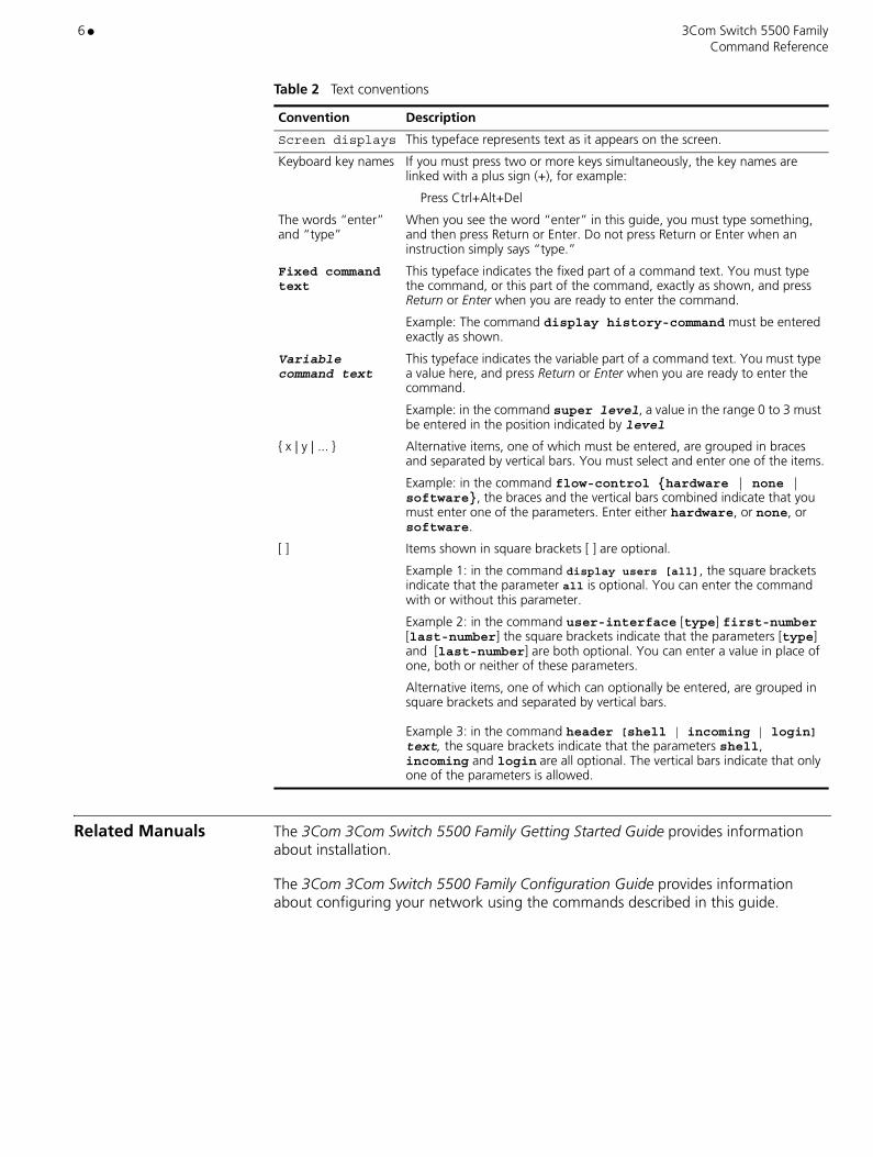
Table 2 Text conventions
Convention Description
Screen displays This typeface represents text as it appears on the screen.
Keyboard key names If you must press two or more keys simultaneously, the key names are linked with a plus sign (+), for example:
Press Ctrl+Alt+Del
The words “enter” and “type”
When you see the word “enter” in this guide, you must type something, and then press Return or Enter. Do not press Return or Enter when an instruction simply says “type.”
Fixed command text
This typeface indicates the fixed part of a command text. You must type the command, or this part of the command, exactly as shown, and press Return or Enter when you are ready to enter the command.
Example: The command display history-command must be entered exactly as shown.
Variable command text
This typeface indicates the variable part of a command text. You must type a value here, and press Return or Enter when you are ready to enter the command.
Example: in the command super level, a value in the range 0 to 3 must be entered in the position indicated by level
{ x | y | ... } Alternative items, one of which must be entered, are grouped in braces and separated by vertical bars. You must select and enter one of the items.
Example: in the command flow-control {hardware | none | software}, the braces and the vertical bars combined indicate that you must enter one of the parameters. Enter either hardware, or none, or software.
[ ]
Items shown in square brackets [ ] are optional.
Example 1: in the command display users [all], the square brackets indicate that the parameter all is optional. You can enter the command with or without this parameter.
Example 2: in the command user-interface [type] first-number [last-number] the square brackets indicate that the parameters [type] and [last-number] are both optional. You can enter a value in place of one, both or neither of these parameters.
Alternative items, one of which can optionally be entered, are grouped in square brackets and separated by vertical bars. Example 3: in the command header [shell | incoming | login] text, the square brackets indicate that the parameters shell, incoming and login are all optional. The vertical bars indicate that only one of the parameters is allowed.

3Com Switch 5500 Family ● 7 Command Reference
ALPHABETICAL LISTING OF COMMANDS
abr-summary 28access-limit 29accounting domain 32accounting optional 35accounting 30accounting-on enable 33acl 37acl 36active region-configuration 39add-member 40address-check 41administrator-address 42am enable 43am ip-pool 44am trap enable 46am user-bind 47apply cost 49apply poe-profile 50apply qos-profile interface 53apply qos-profile 52apply tag 54area 55arp check enable 56arp static 57arp static 58arp timer 60asbr-summary 61ascii 62attribute 63authentication 65authentication-mode 67authentication-mode 68authorization 69auto-build 70auto-execute command 71backup current-configuration to 72binary 74boot attribute-switch 75boot boot-loader backup-attribute 77boot boot-loader 76boot bootrom 78boot web-package 79broadcast-suppression 80broadcast-suppression 81bsr-policy 82

8 ● 3Com Switch 5500 Family Command Reference
build 84bye 85cache-sa-enable 86c-bsr 87cd 89cdup 90change self-unit 91change unit-id 92check region-configuration 93checkzero 95clock datetime 96clock summer-time 97clock timezone 99close 100cluster enable 102cluster switch-to 105cluster 101cluster-mac syn-interval 104cluster-mac 103command-privilege level 106copy configuration 109copy 108count 110crp-policy 111c-rp 88cut connection 113databits 116data-flow-format 115debugging arp packet 119debugging dhcp client 121debugging dhcp server 124debugging dhcp xrn xha 126debugging dhcp xrn xha 127debugging dhcp-relay 122debugging DLDP 128debugging hwtacacs 129debugging igmp 130debugging lacp packet 131debugging lacp state 132debugging link-aggregation error 133debugging link-aggregation event 134debugging mac-authentication event 135debugging msdp 136debugging multicast forwarding 137debugging multicast kernel-routing 138debugging multicast status-forwarding 139debugging ntp-service 140debugging pim common 141debugging pim dm 142debugging pim sm 143debugging resilient-arp 144
3Com Switch 5500 Family ● 9 Command Reference
debugging ssh server 145debugging udp-helper 146debugging vrrp 147debugging webcache 148debugging 117default cost 149default cost 151default interval 152default limit 153default tag 156default type 157default-cost 150default-route-advertise 154delete static-routes all 162delete 159delete 160delete-member 161delete 158description 163description 164destination-ip 165detect-group 166detect-list 167dhcp enable 168dhcp relay information enable 169dhcp relay information strategy 170dhcp select global 171dhcp select interface 173dhcp server detect 176dhcp server dns-list 177dhcp server domain-name 179dhcp server expired 181dhcp server forbidden-ip 183dhcp server ip-pool 186dhcp server nbns-list 187dhcp server netbios-type 189dhcp server option 191dhcp server ping 193dhcp server static-bind 194dhcp server voice-config interface 197dhcp server voice-config 195dhcp-security static 199dhcp-security tracker 200dhcp-server ip 185dhcp-server 175dhcp-snooping trust 202dhcp-snooping 201dir 205dir 203disconnect 206display acl 207

10 ● 3Com Switch 5500 Family Command Reference
display am user-bind 209display am 208display arp timer aging 212display arp 210display boot-loader 213display bootp client 214display brief interface 215display channel 217display clock 218display cluster candidates 221display cluster members 223display cluster 219display config-agent 225display connection 226display cpu 228display current-configuration 229display debugging fabric by-module 235display debugging ospf 236display debugging 233display debugging 234display detect-group 237display device 238display dhcp client 239display dhcp server conflict 243display dhcp server expired 244display dhcp server free-ip 246display dhcp server ip-in-use 248display dhcp server statistics 250display dhcp server tree 252display dhcp-security 240display dhcp-server interface vlan-interface 247display dhcp-server 241display dhcp-snooping trust 255display dhcp-snooping 254display diagnostic-information 256display dldp 257display domain 259display dot1x 260display drv 262display fan 263display fib acl 266display fib ip-prefix 268display fib ip_address 267display fib statistics 269display fib 264display fib 265display ftm 270display ftp source-ip 273display ftp-server source-ip 272display ftp-server 271display ftp-user 274
3Com Switch 5500 Family ● 11 Command Reference
display garp statistics 275display garp timer 276display gvrp statistics 277display gvrp status 278display history-command 279display hwtacacs 280display icmp statistics 281display igmp group 283display igmp interface 284display igmp-snooping configuration 285display igmp-snooping group 286display igmp-snooping statistics 287display info-center 288display interface VLAN-interface 292display interface 289display ip host 293display ip interface vlan-interface 294display ip ip-prefix 295display ip routing-table acl 297display ip routing-table ip-prefix 303display ip routing-table ip_address1 ip_address2 302display ip routing-table ip_address 300display ip routing-table protocol 305display ip routing-table radix 307display ip routing-table statistics 308display ip routing-table verbose 309display ip routing-table 296display ip socket 311display ip statistics 313display isolate port 315display lacp system-id 316display link-aggregation interface 317display link-aggregation summary 319display link-aggregation verbose 320display local-server statistics 321display local-user 322display logbuffer 324display loopback-detection 326display mac-address aging-time 329display mac-address multicast static 330display mac-address 327display mac-authentication 331display memory limit 335display memory 333display memory 334display mirror 336display mirroring-group 337display mpm 339display msdp brief 340display msdp peer-status 341display msdp sa-cache 342

12 ● 3Com Switch 5500 Family Command Reference
display msdp sa-count 344display multicast forwarding-table 345display multicast routing-table 347display multicast-source-deny 349display ndp 350display ntdp device-list 353display ntdp 352display ntp-service sessions 355display ntp-service status 356display ntp-service trace 357display ospf abr-asbr 358display ospf asbr-summary 359display ospf brief 361display ospf cumulative 363display ospf error 365display ospf interface 367display ospf lsdb 369display ospf nexthop 371display ospf peer brief 374display ospf peer statistics 375display ospf peer 372display ospf request-queue 377display ospf retrans-queue 378display ospf routing 379display ospf vlink 380display packet-filter 381display password-control blacklist 383display password-control super 384display password-control 382display pim bsr-info 385display pim interface 386display pim neighbor 387display pim routing-table 388display pim rp-info 390display poe interface 391display poe power supply 395display poe power 393display poe-profile 396display port vlan-vpn 400display port 397display port-security 398display power 401display protocol-priority 402display protocol-vlan interface 403display protocol-vlan vlan 404display qos cos-local-precedence-map 405display qos-interface all 406display qos-interface line-rate 408display qos-interface mirrored-to 409display qos-interface traffic-limit 410display qos-interface traffic-priority 411

3Com Switch 5500 Family ● 13 Command Reference
display qos-interface traffic-statistic 412display qos-profile 413display queue-scheduler 414display radius statistics 416display radius 415display remote-ping 417display resilient-arp 420display rip interface 422display rip 421display rmon alarm 423display rmon event 424display rmon eventlog 425display rmon history unit 428display rmon history 426display rmon prialarm 429display rmon statistics unit 432display rmon statistics 430display route-policy 433display rsa local-key-pair public 434display rsa peer-public-key 435display saved-configuration 436display schedule reboot 439display sftp source-ip 440display snmp-agent community 442display snmp-agent group 443display snmp-agent mib-view 444display snmp-agent statistics 445display snmp-agent sys-info 447display snmp-agent trap-list 448display snmp-agent usm-user 449display snmp-agent 441display snmp-proxy unit 450display ssh server 451display ssh server-info 452display ssh user-information 454display ssh-server source-ip 453display ssh2 source-ip 455display startup 456display stop-accounting buffer 457display stp ignored-vlan 460display stp region-configuration 461display stp tc 462display stp 458display tcp statistics 463display tcp status 465display telnet-server source-ip 466display tftp source-ip 467display this 468display time-range 469display transceiver-information interface 470display trapbuffer 471
14 ● 3Com Switch 5500 Family Command Reference
display udp statistics 473display udp-helper server 472display unit 474display user-interface 475display users 477display version 478display vlan 479display vlan 480display voice vlan oui 482display voice vlan status 483display vrrp 484display webcache 486display xrn-fabric 487dldp authentication-mode 490dldp interval 491dldp reset 492dldp unidirectional-shutdown 493dldp work-mode 494dldp 488dns-list 495domain 496domain-name 498dot1x authentication-method 501dot1x authentication-method 502dot1x dhcp-launch 503dot1x guest-vlan 504dot1x max-user 506dot1x port-control 507dot1x port-method 509dot1x quiet-period 511dot1x retry 512dot1x retry-version-max 513dot1x supp-proxy-check 514dot1x timer ver-period 518dot1x timer 516dot1x version-check 519dot1x 499duplex 520enable snmp trap updown 521end-station polling ip-address 522execute 523exit 524expired 525fabric port enable 526file prompt 527filter-policy export 528filter-policy export 529filter-policy export 531filter-policy import 532filter-policy import 534filter-policy import 536
3Com Switch 5500 Family ● 15 Command Reference
fixdisk 538flow-control 539flow-control 540format 541free user-interface 542free web-users 543frequency 544ftm stacking-vlan 545ftp cluster 547ftp dir 550ftp disconnect 551ftp server enable 553ftp source-interface 556ftp source-ip 557ftp timeout 558ftp { cluster | remote-server } source-interface 548ftp { cluster | remote-server } source-ip 549ftp 546ftp-server source-interface 554ftp-server source-ip 555ftp-server 552garp timer leaveall 561garp timer 559gateway-list 562get 563gratuitous-arp learning enable 564gvrp registration 566gvrp 565header 567help 570history-command max-size 571holdtime 572host-route 573hwtacacs nas-ip 574hwtacacs scheme 575icmp 576idle-cut 577idle-timeout 578if-match cost 580if-match interface 581if-match ip next-hop 582if-match tag 583if-match { acl | ip-prefix } 579igmp enable 584igmp group-limit 585igmp group-policy 586igmp host-join 588igmp lastmember-queryinterval 589igmp max-response-time 591igmp proxy 592igmp robust-count 593
16 ● 3Com Switch 5500 Family Command Reference
igmp timer other-querier-present 603igmp timer query 604igmp version 605igmp-snooping fast-leave 596igmp-snooping group-limit 597igmp-snooping group-policy 598igmp-snooping host-aging-time 600igmp-snooping max-response-time 601igmp-snooping router-aging-time 602igmp-snooping 595import-route 607import-route 606import-source 609info-center channel name 610info-center console channel 611info-center enable 612info-center logbuffer 613info-center loghost source 616info-center loghost 614info-center monitor channel 617info-center snmp channel 618info-center source 619info-center switch-on 623info-center synchronous 625info-center timestamp loghost 627info-center timestamp 626info-center trapbuffer 628instance 629interface VLAN-interface 632interface 631ip address bootp-alloc 635ip address dhcp-alloc 636ip address 633ip host 637ip http acl 638ip ip-prefix 639ip route-static 642ip-pool 641jumboframe enable 643key 644lacp enable 645lacp port-priority 646lacp system-priority 647language-mode 648lcd 649level 650line-rate 651link-aggregation group agg-id description 652link-aggregation group agg-id mode 653local-server 654local-user password-display mode 656

3Com Switch 5500 Family ● 17 Command Reference
local-user 655lock 657logging-host 658loopback 659loopback-detection control enable 660loopback-detection enable 661loopback-detection interval-time 663loopback-detection per-vlan enable 664ls 665mac-address max-mac-count 667mac-address multicast interface vlan 668mac-address multicast vlan 669mac-address timer 670mac-address 666mac-authentication authmode 673mac-authentication authpassword 674mac-authentication authusername 675mac-authentication domain 676mac-authentication timer 677mac-authentication 671management-vlan 678mdi 679memory auto-establish disable 680memory auto-establish enable 681memory { safety | limit } 682messenger 684mirrored-to 685mirroring group 687mirroring-group mirroring-port 688mirroring-group monitor-port 689mirroring-group reflector-port 690mirroring-group remote-probe vlan 691mirroring-port 692mkdir 693monitor-port 694more 695move 696msdp 697msdp-tracert 698multicast route-limit 700multicast routing-enable 701multicast-source-deny 702multicast-suppression 704name 705nas-ip 706nbns-list 707ndp enable 708ndp timer aging 709ndp timer hello 710netbios-type 711network 712
18 ● 3Com Switch 5500 Family Command Reference
nm-interface vlan-interface 714nssa 715ntdp enable 716ntdp explore 717ntdp hop 718ntdp timer hop-delay 720ntdp timer port-delay 721ntdp timer 719ntp-service access 722ntp-service authentication enable 723ntp-service authentication-keyid 724ntp-service broadcast-client 725ntp-service broadcast-server 726ntp-service in-interface disable 727ntp-service max-dynamic sessions 728ntp-service multicast-client 729ntp-service multicast-server 730ntp-service reliable authentication-keyid 731ntp-service source-interface 732ntp-service unicast-peer 733ntp-service unicast-server 735option 737originating-rp 738ospf authentication-mode 740ospf cost 742ospf dr-priority 743ospf mib-binding 744ospf mtu-enable 745ospf network-type 746ospf timer dead 748ospf timer hello 749ospf timer poll 750ospf timer retransmit 751ospf trans-delay 752ospf 739packet-filter 753packet-filter 754parity 755passive 756password 757password 758password-control enable 762password-control super 764password-control 759peer connect-interface 767peer description 768peer mesh-group 769peer minimum-ttl 770peer request-sa-enable 772peer sa-cache-maximum 773peer sa-policy 774

3Com Switch 5500 Family ● 19 Command Reference
peer sa-request-policy 775peer-public-key end 771peer 765peer 766pim bsr-boundary 777pim dm 778pim neighbor-limit 779pim neighbor-policy 780pim sm 781pim timer hello 782pim 776ping 783pki 786poe enable 787poe legacy enable 788poe max power 789poe mode 790poe power-management 791poe priority 792poe update 794poe-profile 793port access vlan 796port hybrid protocol-vlan vlan 797port hybrid pvid vlan 798port hybrid vlan 799port isolate 800port link-aggregation group 801port link-type 802port trunk permit vlan 817port trunk pvid vlan 818port 795port-security enable 803port-security intrusion-mode 804port-security max-mac-count 806port-security ntk-mode 807port-security OUI 809port-security port-mode 810port-security timer disableport 813port-security trap 814port-tagged 816preference 819preference 820primary accounting 821primary authentication 822primary authorization 823priority trust 825priority 824protocol inbound 826protocol-priority protocol-type 827protocol-vlan 828public-key-code begin 830

20 ● 3Com Switch 5500 Family Command Reference
public-key-code begin 831public-key-code end 832put 833pwd 834qos cos-local-precedence-map 839qos-profile 841queue-scheduler 835quit 837quit 838radius nas-ip 842radius scheme 844radius-scheme 843reboot member 847reboot 846region-name 848register-policy 849remotehelp 854remote-ping 850remote-ping-agent enable 852remote-probe vlan 853remove 855rename 856reset acl counter 858reset arp 859reset counters interface 860reset dhcp server conflict 861reset dhcp server ip-in-use 862reset dhcp server statistics 863reset dot1x statistics 864reset garp statistics 865reset hwtacacs statistics 866reset igmp group 867reset igmp-snooping statistics 868reset ip statistics 869reset lacp statistics 870reset logbuffer 871reset msdp peer 872reset msdp sa-cache 873reset msdp statistics 874reset multicast forwarding-table 875reset multicast routing-table 877reset ndp statistics 878reset ospf all 879reset password-control blacklist 880reset password-control history-record super 882reset password-control history-record 881reset pim neighbor 883reset pim routing-table 884reset radius statistics 886reset recycle-bin 887reset saved-configuration 888
3Com Switch 5500 Family ● 21 Command Reference
reset stop-accounting-buffer 890reset stp 891reset tcp statistics 892reset traffic-statistic 893reset trapbuffer 895reset udp statistics 896reset vrrp statistics 897reset 857resilient-arp enable 898resilient-arp interface vlan-interface 899restore startup-configuration from 900retry realtime-accounting 902retry stop-accounting 903retry 901return 904revision-level 905rip authentication-mode 907rip input 909rip metricin 910rip metricout 911rip output 912rip split-horizon 913rip version 914rip work 915rip 906rmdir 916rmon alarm 917rmon event 918rmon history 919rmon prialarm 920rmon statistics 922route-policy 923router id 925rsa local-key-pair create 926rsa local-key-pair destroy 928rsa peer-public-key 929rule 930save 934schedule reboot at 936schedule reboot delay 938scheme 940screen-length 941secondary accounting 942secondary authentication 943secondary authorization 944security-policy-server 945self-service-url 946send 947server-type 948service-type multicast 953service-type 949
22 ● 3Com Switch 5500 Family Command Reference
service-type 951set authentication password 954set unit name 955sftp server enable 958sftp source-interface 959sftp source-ip 960sftp time-out 961sftp 956shell 962shutdown 963silent-interface 964snmp-agent community 965snmp-agent group 968snmp-agent group 966snmp-agent local-engineid 970snmp-agent log 971snmp-agent mib-view 972snmp-agent packet max-size 973snmp-agent sys-info 974snmp-agent target-host 975snmp-agent trap enable ospf 979snmp-agent trap enable 977snmp-agent trap life 981snmp-agent trap queue-size 982snmp-agent trap source 983snmp-agent usm-user 986snmp-agent usm-user 984snmp-host 988source-policy 989speed 990speed 991spf-schedule-interval 992ssh client assign rsa-key 993ssh client first-time enable 994ssh server authentication-retries 995ssh server rekey-interval 997ssh server timeout 999ssh user assign rsa-key 1000ssh user authentication-type 1001ssh user service-type 1003ssh user username authentication-type 1004ssh-server source-interface 996ssh-server source-ip 998ssh2 source-interface 1007ssh2 source-ip 1008ssh2 1005standby detect-group 1009startup bootrom-access enable 1019startup saved-configuration 1020state 1010state 1011

3Com Switch 5500 Family ● 23 Command Reference
static-bind ip-address 1013static-bind mac-address 1015static-rp 1016static-rpf-peer 1017stop-accounting-buffer enable 1022stopbits 1023stp bpdu-protection 1025stp bridge-diameter 1026stp cost 1027stp edged-port 1028stp ignored vlan 1030stp interface cost 1032stp interface edged-port 1034stp interface loop protection 1036stp interface mcheck 1037stp interface point-to-point 1038stp interface port priority 1040stp interface root-protection 1041stp interface transmit-limit 1043stp interface 1031stp loop-protection 1044stp max-hops 1045stp mcheck 1046stp mode 1047stp pathcost-standard 1048stp point-to-point 1050stp port priority 1052stp priority 1053stp region-configuration 1054stp root primary 1055stp root secondary 1058stp root-protection 1057stp tc-protection 1060stp timeout-factor 1061stp timer forward-delay 1063stp timer hello 1065stp timer max-age 1066stp timer-factor 1062stp transmit-limit 1067stp 1024stub 1068summary 1069super password 1071super 1070sysname 1072sysname 1073sysname 1074system-view 1075tcp timer fin-timeout 1076tcp timer syn-timeout 1077tcp window 1078

24 ● 3Com Switch 5500 Family Command Reference
telnet source-interface 1082telnet source-ip 1083telnet 1079telnet-server source-interface 1080telnet-server source-ip 1081terminal debugging 1084terminal logging 1085terminal monitor 1086terminal trapping 1087test-enable 1088test-type 1089tftp cluster get 1090tftp cluster put 1091tftp get 1092tftp put 1093tftp source-interface 1095tftp source-ip 1096tftp tftp-server source-interface 1097tftp tftp-server source-ip 1098tftp-server 1094timeout 1101timer loop 1103timer quiet 1104timer realtime-accounting 1105timer response-timeout 1106timer retry 1107timer wait 1108timer 1102time-range 1099timers 1109tracert 1110traffic-limit 1114traffic-limit 1112traffic-priority 1118traffic-priority 1116traffic-redirect 1120traffic-share-across-interface 1122traffic-statistic 1123udp-helper enable 1125udp-helper port 1126udp-helper server 1127undelete 1128undo snmp-agent 1129unicast-suppression 1130update fabric 1131user privilege level 1136user 1133user-interface 1134user-name-format 1135verbose 1137virtual-cable-test 1138

3Com Switch 5500 Family ● 25 Command Reference
vlan to 1145vlan-assignment-mode 1141vlan-mapping modulo 1143vlan-vpn enable 1146vlan-vpn inner-cos-trust 1147vlan-vpn tpid 1148vlan-vpn tunnel 1149vlan-vpn uplink enable 1150vlan�����vlink-peer 1151voice vlan aging 1156voice vlan enable 1157voice vlan mac-address 1159voice vlan mode 1158voice vlan security enable 1160voice vlan 1155voice-config 1153vrrp authentication-mode 1161vrrp method 1163vrrp ping-enable 1164vrrp vlan-interface vrid track 1165vrrp vrid preempt-mode 1166vrrp vrid priority 1167vrrp vrid timer advertise 1168vrrp vrid track detect-group 1171vrrp vrid track 1169vrrp vrid virtual-ip 1172wred 1173xmodem 1174xrn-fabric authentication-mode 1175

26 ● 3Com Switch 5500 Family Command Reference

COMMANDS

28 ● abr-summary 3Com Switch 5500 Family Command Reference
abr-summary
Purpose Use the abr-summary command to configure route aggregation on the area border router.
Use the undo abr-summary command to disable route aggregation on the area border router. This is the default.
Syntax abr-summary ip_address mask [ advertise | not-advertise ]
undo abr-summary ip_address mask
Parameters ip_address Specifies a network segment IP address.
mask Specifies the subnet mask.
advertise Specifies to advertise only the summarized route.
not advertise Specifies to not advertise routes matching the specified IP address and mask.
Example To enter area 1, and then aggregate the network segments, 66.48.10.0 and 66.48.120.0 into the summary route 66.48.0.0, enter the following:
<SW5500>system-viewSystem View: return to User View with Ctrl+Z.[SW5500]router id 1.1.1.1[SW5500]ospf[SW5500-ospf-1]area 1[SW5500-ospf-1-area-0.0.0.1]network 66.48.10.0 0.0.0.255[SW5500-ospf-1-area-0.0.0.1]network 66.48.120.0 0.0.0.255[SW5500-ospf-1-area-0.0.0.1]abr-summary 66.48.0.0 255.255.0.0
View This command can be used in the following views:
■ OSPF Area view
Description This command is applicable only to an area border router (ABR) and is used for the route aggregation in an area. The ABR only transmits an aggregated route to other areas. Route aggregation refers to the routing information that is processed in the ABR. For each network segment configured with route aggregation, there is only one route transmitted to other areas.

3Com Switch 5500 Family access-limit ● 29 Command Reference
access-limit
Purpose Use the access-limit command to configure a limit to the amount of supplicants in the current ISP domain.
Syntax access-limit { disable | enable max-user-number }
Parameters disable No limit to the supplicant number in the current ISP domain. If not specified, disable is selected by default.
enable max-user-number Specifies the maximum supplicant number in the current ISP domain. Valid values are 1 to 1048.
Example Sets a limit of 500 supplicants for the ISP domain, marlboro.net.
<SW5500>system-viewSystem View: return to User View with Ctrl+Z.[SW5500]domain marlboro.netNew domain added.[SW5500-isp-marlboro.net]access-limit enable 500
View This command can be used in the following views:
■ ISP Domain view
Description This command limits the amount of supplicants contained in the current ISP domain. The supplicants may contend with each other for the network resources. So setting a suitable limit to the amount will guarantee the reliable performance for the existing supplicants.
30 ● accounting 3Com Switch 5500 Family Command Reference
accounting
Purpose Use the accounting command to configure an accounting scheme for the current ISP domain.
Use the undo accounting command to cancel the accounting scheme configuration of the current ISP domain.
Syntax accounting { none | radius-scheme radius-scheme-name }
undo accounting
Parameters none Specifies not to perform accounting.
radius-scheme-name Name of a RADIUS scheme, consisting of a character string no more than 32 characters long.
Default By default, no accounting scheme is configured for the ISP domain.
Example Enter system view.
<S5500> system-view
Create an ISP domain named aabbcc.net.
[S5500] domain aabbcc.netNew Domain added.
Specify the scheme radius as the RADIUS accounting scheme that will be referenced by the current ISP domain aabbcc.net.
[S5500-isp-aabbcc.net] accounting radius-scheme radius
View This command can be used in the following views:
■ ISP Domain view
Description When you use the accounting command to specify a RADIUS scheme to be referenced by the current ISP domain, the RADIUS scheme must has already been defined.
If the accounting command is executed in an ISP domain view, the system uses the accounting scheme specified in this command to charge the users in the domain. Otherwise, the system uses the scheme specified in the scheme command to charge the users.

3Com Switch 5500 Family accounting ● 31 Command Reference
Related Command ■ scheme
■ radius scheme

32 ● accounting domain 3Com Switch 5500 Family Command Reference
accounting domain
Purpose Use the accounting domain command to enable the DHCP accounting function.
Use the undo accounting domain command to disable the DHCP accounting function.
Syntax accounting domain domain-name
undo accounting domain
Parameters domain-name Name of a domain, consisting of a string from 1 to 24 characters long. (You can use the domain command to create a domain.)
Example Enter system view.
<S5500> system-viewSystem View: return to User View with Ctrl+Z.
Enter DHCP address pool view.
[S5500] dhcp server ip-pool test
Enable the DHCP accounting function (assuming that domain 123 already exists).
[S5500-dhcp-pool-test] accounting domain 123
View This command can be used in the following views:
■ DHCP Address Pool view

3Com Switch 5500 Family accounting-on enable ● 33 Command Reference
accounting-on enable
Purpose Use the accounting-on enable command to enable user re-authentication at reboot.
Use the undo accounting-on enable command to disable user re-authentication at reboot and restore the default interval and maximum times to transmit Accounting-On packet.
Use the undo accounting-on send command to restore the default maximum times to transmit Accounting-On packet.
Use the undo accounting-on interval command to restore the default interval to transmit Accounting-On packet.
Syntax accounting-on enable [ send times | interval interval ]
undo accounting-on { enable | send | interval }
Parameters times Maximum times to send Accounting-On packet, ranging from 1 to 256. If not specified, the default is 15 times.
interval Interval to send Accounting-On packet, ranging from 1 to 30. If not specified, the default is 3 (in seconds).
Default By default, this feature is disabled.
Example Enter system view.
<S5500> system-view
Enter the view of the RADIUS scheme named CAMS (supposing this scheme has already existed).
[S5500] radius scheme CAMS
Enable user re-authentication at reboot.
[S5500-radius-CAMS] accounting-on enable
View This command can be used in the following views:
■ RADIUS Scheme view
34 ● accounting-on enable 3Com Switch 5500 Family Command Reference
Description The purpose of this feature is to resolve the following problem: users cannot re-log onto the network after the switch reboots because they are already online. After this feature is enabled, every time the switch reboots:
■ The switch generates an Accounting-On packet, which mainly contains the following information: NAS-ID, NAS-IP (source IP address), and session ID.
■ The switch sends the Accounting-On packet to the CAMS at regular intervals.
■ Once the CAMS receives the Accounting-On packet, it sends a response to the switch. At the same time it finds and deletes the existing online information of the user who was accessing the network through the switch before the reboot based on the NAS-ID, NAS-IP and session ID contained in the Accounting-On packet, and ends the charging of the user according to the last accounting update packet.
■ Once the switch receives the response from the CAMS, it stops sending other Accounting-On packets.
■ If the switch has tried the set maximum times to transmit the Accounting-On packet but still does not receive any response from the CAMS, it stops the sending of the Accounting-On packet.
Note: The switch can automatically generate the main attributes (NAS-ID, NAS-IP and session ID) of the Accounting-On packets. However, you can also manually configure the NAS-IP attribute with the nas-ip command. When doing this, be sure to configure a correct and valid IP address. If this attribute is not configured manually, the switch will automatically select the IP address of the VLAN interface as the NAS-IP address.
Related Command nas-ip
3Com Switch 5500 Family accounting optional ● 35 Command Reference
accounting optional
Purpose Use the accounting optional command to enable the selection of the RADIUS accounting option.
Use the undo accounting optional command to disable the selection of RADIUS accounting option.
Syntax accounting optional
undo accounting optional
Parameters None
Default By default, selection of the RADIUS accounting option is disabled.
Example Enable the selection of RADIUS accounting of the RADIUS scheme named as CAMS.
<SW5500>system-viewSystem View: return to User View with Ctrl+Z.[SW5500]radius scheme camsNew Radius scheme[SW5500-radius-cams]accounting optional
View This command can be used in the following views:
■ ISP Domain view
Description If no RADIUS server is available or if RADIUS accounting server fails when the accounting optional is configured, the user can still use the network resource, otherwise, the user will be disconnected.
The user configured with accounting optional command in RADIUS scheme will no longer send real-time accounting update packet or stop accounting packet.
The accounting optional command in RADIUS Scheme View is only effective on the accounting that uses this RADIUS scheme.
36 ● acl 3Com Switch 5500 Family Command Reference
acl
Purpose Use the acl command to reference ACL and implement the ACL control to the TELNET users.
Use the undo acl command to remove the control from the TELNET users.
Syntax acl acl-number { inbound | outbound }
undo acl { inbound | outbound }
Parameters acl-number The number identifier of basic and advanced number-based ACLs. Valid values are 2000 to 3999.
inbound Performs ACL control to the users who access the local Switch using TELNET.
outbound Performs ACL control to the users who access other Switches from the local Switch using TELNET.
Example Perform ACL control to the users who access the local Switch using TELNET (basic ACL 2000 has been defined).
<SW5500>system-viewSystem View: return to User View with Ctrl+Z[SW5500]user-interface vty 0 4[SW5500-ui-vty0-4]acl 2000 inbound[SW5500-ui-vty0-4]
View This command can be used in the following views:
■ User Interface view

3Com Switch 5500 Family acl ● 37 Command Reference
acl
Purpose Use the acl command to define an ACL identified by a number, and enter the corresponding ACL View.
Use the undo acl command to cancel all sub-items of an ACL identified by a number, or cancel the entire ACL.
Syntax acl number acl-number [ match-order { config | auto } ]
undo acl { number acl-number | all }
Parameters number acl-number the sequence number of an Access Control List (ACL), the range is:
2000~2999: Basic ACL.
3000~3999: Advanced ACL.
4000~4999: Layer 2 ACL.
5000~5999: User-defined ACL.
config Follow the user configuration order to match ACL rules.
auto Follow the depth-first order to match ACL rules.
all ( for the undo command)Cancel all the ACLs.
Default By default, the ACLs are matched in config order.
Example Specify depth first order as the match order of number 2000 ACL.
<SW5500>system-viewSystem View: return to User View with Ctrl+Z[SW5500]acl number 2000 match-order auto[SW5500-acl-basic-2000]
View This command can be used in the following views:
■ System view
Description After entering a corresponding ACL View, you can use the rule command to create sub-items of this ACL (you can exit the ACL View by using the quit command).
Using the match-order, you can specify whether the match order is the user’s configuration order or depth first order (it first matches the rules with a small range); if not specified, then the user’s configuration order will be chosen by default. Once the matching order of the ACL is specified, you cannot change the order unless you have cancelled all the sub-items. Note that the ACL matching order is in effect only

38 ● acl 3Com Switch 5500 Family Command Reference
when the ACL is employed by the software as a means of data filtering and classification.
Related Command rule
3Com Switch 5500 Family active region-configuration ● 39 Command Reference
active region-configuration
Purpose Use the active region-configuration command to activate the settings of an MST (multiple spanning tree) region.
Syntax active region-configuration
Parameters None
Example Activate the MST region settings.
<S5500> system-view System View: return to User View with Ctrl+Z.[S5500s5500] stp region-configuration [S5500-mst-region] active region-configuration
View This command can be used in the following views:
■ MST Region view
Description This command causes the switch to operate with the new MST region settings, when spanning trees are regenerated.
Changes of MST region parameters, especially those of the VLAN mapping tables, can cause MSTP to recalculate the spanning trees, creating network topology jitters across the network. To reduce network topology jitters caused by configuration changes, MSTP does not recalculate the spanning trees immediately in response to region configuration changes. Rather, MSTP brings the configurations into effect only after you activate the new MST region settings or enable MSTP.
Related Commands ■ check region-configuration
■ instance
■ region-name
■ revision-level
■ vlan-mapping modulo
40 ● add-member 3Com Switch 5500 Family Command Reference
add-member
Purpose Use the add-member command to add a candidate device to a cluster.
Syntax add-member [ member-number] mac-address H-H-H [ password password ]
Parameters member-number Number of a member device. Valid values are 1 to 255.
H-H-H Hexadecimal MAC address of a member device.
password Password of a candidate device. Valid values are 1 to 256. Before joining a cluster, the candidate device needs to be authenticated. A candidate without password does not need this setting.
Example Add a candidate device with MAC address 00E0-fc00-35e7 and user password 123456 to the cluster, and specify member number 6 for it.
<aaa_0.S5500>system-viewSystem View: return to User View with Ctrl+Z.[aaa_0.S5500]cluster[aaa_0.S5500-cluster] add-member 6 mac-address 00E0-fc00-35e7 password 123456
View This command can be used in the following views:
■ Cluster view
Description This command can be executed on the management device only, otherwise an error message appears.
If you do not specify the member number when adding a cluster member, the management device will assign the next available number for it.
After the candidate device is added into the cluster, its device password will become the management device password.
3Com Switch 5500 Family address-check ● 41 Command Reference
address-check
Purpose Use the address-check command to enable or disable DHCP relay security on a VLAN interface, so as to start the validity check on user addresses under the VLAN interface.
Syntax address-check enable
address-check disable
Parameters None
Default By default, DHCP relay security is disabled on a VLAN interface.
Example To enter system view and enter the VLAN 1 interface view, enter the following:
<S5500> system-viewSystem View: return to User View with Ctrl+Z.[S5500] interface vlan-interface 1
To enable DHCP relay security on VLAN 1 interface, enter the following:
[S5500-Vlan-interface1] address-check enable
View This command can be used in the following views:
■ VLAN Interface view
Description Among Switch 5500-series switches, only Switch 5500 El-series switches support the two commands.
42 ● administrator-address 3Com Switch 5500 Family Command Reference
administrator-address
Purpose Use the administrator-address command to store the MAC address of the management device on a member device.
Use the undo administrator-address command to remove a member from the cluster, usually for debugging or restoration.
Syntax administrator-address mac-address name name
undo administrator-address
Parameters mac-address MAC address of the management device.
name Name of an existing cluster consisting of no more than 8 characters, including only alphanumeric characters, subtraction sign “-” and/or underline “_”
Default By default, a switch is not in any cluster.
Example Remove the current member device from the cluster.
<aaa_1.S5500>system-viewSystem View: return to User View with Ctrl+Z[aaa_1.S5500] cluster[aaa_1.S5500] undo administrator-address
View This command can be used in the following views:
■ Cluster view
Description Only one management device exists in a cluster. When the system reboots, member devices can recognize the administer device by its MAC address.
The recommended way to remove a cluster member is to execute the delete-member command.

3Com Switch 5500 Family am enable ● 43 Command Reference
am enable
Purpose Use the am enable command to enable address management IP address pool.
Use the undo am enable command to disable address management IP address pool.
Syntax am enable
undo am enable
Parameters None
Default By default, address management IP address pool is disabled on the switch.
Example Enable address management IP address pool.
<S5500> system-viewSystem View: return to User View with Ctrl+Z.[S5500] am enable
View This command can be used in the following views:
■ System view
Description Notice:
■ 3Com recommends you remove static ARP configuration before enabling address management IP address pool. This ensures that the binding of an IP address to the Ethernet switch takes effect.
■ If you have configured on another port to implement static ARP on an IP address within the IP address pool on the current port, the system will prompt you to remove that ARP setting.

44 ● am ip-pool 3Com Switch 5500 Family Command Reference
am ip-pool
Purpose Use the am ip-pool command to set an address management IP address pool for a port, permitting the packets in this IP address pool whose IP addresses are the source IP addresses to pass the port for layer 3 forwarding.
Use the undo am ip-pool command to remove part or all of the IP addresses in the address management IP address pool on a port.
Syntax am ip-pool address-list
undo am ip-pool { all | address-list }
Parameters all Carries out the operation on all IP addresses (pools).
ip-pool Configures an address management IP address pool.
address-list Lists IP address ranges. This list is a combination of IP address segments and specific IP addresses. An IP address segment is in the form of start_ip_address [ ip_address_num ] & < 1-10 >, where start_ip_address is the starting IP address of an IP address range in the IP address pool, ip_address_num indicates the number of consecutive IP addresses starting from start_ip_address, and & < 1-10 > means that up to 10 address segments can be specified.
Default By default, address management IP address pools on all ports are null and the switch permits all packets to pass.
Example Configure an address management IP address pool on Ethernet1/0/1, allowing the IP addresses ranging from 202.112.66.2 to 202.112.66.20 and the specified IP address 202.112.65.1 to access the network through the port.
<S5500> system-viewSystem View: return to User View with Ctrl+Z.[S5500] interface ethernet1/0/1[S5500-Ethernet1/0/1] am ip-pool 202.112.66.2 19 202.112.65.1
View This command can be used in the following views:
■ Ethernet Port view
Description Notice:
When you are configuring an address management IP address pool on a port, if the IP addresses in this IP address pool are those configured in the static ARP on another

3Com Switch 5500 Family am ip-pool ● 45 Command Reference
port, the system will prompt you to delete the corresponding static ARP to ensure that the binding takes effect.
Note that when you are configuring an address management IP address pool on a port, if the IP addresses in this IP address pool are those configured in the static ARP on another port, the system will prompt you to delete the corresponding static ARP to ensure that the binding takes effect.
46 ● am trap enable 3Com Switch 5500 Family Command Reference
am trap enable
Purpose Use the am trap enable command to enable the access management trap function.
Use the undo am trap enable command to disable the access management trap function.
Syntax am trap enable
undo am trap enable
Parameters None
Default By default, the access management trap is disabled.
Example To enable the access management trap, enter the following:
<SW5500>system-viewSystem View: return to User View with Ctrl+Z.[SW5500]am trap enable
View This command can be used in the following views:
■ System view

3Com Switch 5500 Family am user-bind ● 47 Command Reference
am user-bind
Purpose Use the am user-bind command to bind the MAC address and IP address of a legal user to the specified port.
Use the undo am user-bind command to remove the binding of the MAC address and IP address to the specified port.
Syntax In system view:
am user-bind mac-addr mac-address ip-addr ip-address interface interface-type interface-number
undo am user-bind mac-addr mac-address ip-addr ip-address interface interface-type interface-number
In Ethernet port view:
am user-bind mac-addr mac-address ip-addr ip-address
undo am user-bind mac-addr mac-address ip-addr ip-address
Parameters mac-address Specifies the MAC address to be bound.
ip-address Specifies the IP address to be bound.
interface-type Specifies the type of interface to be bound.
interface-number Specifies the number of the interface to be bound.
Example Bind a legal user whose MAC address is 00e0-fc00-5500 and whose IP address is 10.153.1.1 to Ethernet1/0/2.
<S5500> system-viewSystem View: return to User View with Ctrl+Z.[S5500] am user-bind mac-addr 00e0-fc00-5500 ip-addr 10.153.1.1 interface Ethernet1/0/2
CAUTION:
The am user-bind command is related to none of the following commands:
■ The am enable command, which enables address management in system view
■ The am ip-pool { address-list } command, which sets an address management IP address pool on a port in Ethernet port view
For detailed descriptions on the am enable command and the am ip-pool { address-list } command, see the "Network Protocol" module in S5500 Series Ethernet Switches Command Manual.
48 ● am user-bind 3Com Switch 5500 Family Command Reference
View This command can be used in the following views:
■ System view
■ Ethernet Port view
Description After the binding, only packets from a legal user can pass the port.
A legal user
■ Has a MAC address that is bound by using the am user-bind command.
■ Has an IP address that is bound by using the am user-bind command.
�
Notice:
■ You can bind up to 128 MAC addresses and IP addresses to one port.
■ The system allows you to bind the same MAC address only once.
■ The system allows you to bind the same IP address only once.

3Com Switch 5500 Family apply cost ● 49 Command Reference
apply cost
Purpose Use the apply cost command to configure the route cost value of route information.
Use the undo apply cost command to cancel the apply sub-statement.
Syntax apply cost value
undo apply cost
Parameters value Enter the route cost value of route information.
Example Define one apply sub-statement. When it is used for setting route information attribute, it sets the route metric value of route information to 120.
<SW5500>system-viewSystem View: return to User View with Ctrl+Z.[SW5500]route-policy permit node 1
% New sequence of this list[SW5500-route-policy]apply cost 120
View This command can be used in the following views:
■ Route Policy view
Description This command is one of the apply sub-statements of the Route-policy attribute set.
Related Commands ■ if-match interface
■ if-match { acl | ip-prefix }
■ if-match ip next-hop
■ if-match cost
■ if-match tag
■ route-policy
■ apply tag
50 ● apply poe-profile 3Com Switch 5500 Family Command Reference
apply poe-profile
Purpose Use the apply poe-profile command to apply the existing PoE Profile configuration to the specified Ethernet port.
Use the undo apply poe-profile command to delete the PoE Profile configuration for the specified Ethernet port.
Syntax Under system view use the following commands:
apply poe-profile profilename interface interface-type interface-number [ to interface-type interface-number ]
undo apply poe-profile profilename interface interface-type interface-number [ to interface-type interface-number ]
Under Ethernet port view use the following commands:
apply poe-profile profilename
undo apply poe-profile profilename
Parameters profilename Name of PoE Profile, consisting of a string 1 to 15 characters long, and cannot be reserved keywords like all, interface, user, undo, and mode.
interface-type interface-type indicates type of the interface.
interface-number interface-number specifies the port ID.
Example Apply the existing PoE Profile (profile-test) configuration to Ethernet1/0/1 through Ethernet1/0/9 ports of the switch.
<S5500> system-viewSystem View: return to User View with Ctrl+Z.[S5500] apply poe-profile profile-test interface ethernet1/0/1 to ethernet1/0/9
View This command can be used in the following views:
■ System view
Description Only one PoE Profile can be in use at any time for each Ethernet port.
Various PoE features can be configured within one PoE Profile. The following holds while using the apply poe-profile command to apply a PoE Profile to a group of ports.
■ The display current-configuration command can be used to indicate that the PoE Profile is being used properly, so long as one PoE feature in the PoE Profile is in proper use for a given port.

3Com Switch 5500 Family apply poe-profile ● 51 Command Reference
■ If one or more features of the PoE Profile are not used properly in a given port, the terminal will show clearly exactly which feature on what port is not used properly.
52 ● apply qos-profile 3Com Switch 5500 Family Command Reference
apply qos-profile
Purpose Use the apply qos-profile command to apply the QoS profile to the current port.
Use the undo apply qos-profile command to remove the QoS profile from a port.
Syntax apply qos-profile profile-name
undo apply qos-profile profile-name
Parameters profile-name QoS profile name, consisting of a string 1 to 32 characters long, starting with letters [a-z, A-Z] and excluding all, interface, and user which are reserved as keywords.
Example To apply the qos-profile student to the current port, enter the following:
<SW5500>system-viewSystem View: return to User View with Ctrl+Z[SW5500]interface Ethernet 1/0/1[SW5500-Ethernet1/0/1] apply qos-profile student[SW5500-Ethernet1/0/1]
View This command can be used in the following views:
■ Ethernet Port view
Description You cannot delete a QoS profile which has been applied to a port. Likewise a profile has to be created before it can be assigned to a port.

3Com Switch 5500 Family apply qos-profile interface ● 53 Command Reference
apply qos-profile interface
Purpose Use the apply qos-profile interface command to apply a QoS profile to one or more consecutive ports.
Use the undo apply qos-profile command to remove the configuration.
Syntax apply qos-profile profile-name interface { interface-name | interface-type interface-num } [ to interface { interface-name | interface-type interface-num } ]
undo apply qos-profile profile-name interface { interface-name | interface-type interface-num } [ to interface { interface-name | interface-type interface-num } ]
Parameters profile-name QoS profile name, a string of one to 32 characters, starting with English letters [a-z, A-Z] and excluding all, interface, user and others that are reserved as keywords.
interface { interface-name | interface-type interface-num } [ to interface { interface-name | interface-type interface-num } ] A group of consecutive ports. The first interface {
interface-name | interface-type interface-num } is the starting port and the second one is the end port.
Example To apply the qos-profile student to the ports Ethernet1/0/1 through Ethernet1/0/4, enter the following:
<SW5500>system-viewSystem View: return to User View with Ctrl+Z[SW5500]apply qos-profile qos-profile student interface e1/0/1 to e1/0/4[SW5500]
View This command can be used in the following views:
■ System view
Description You cannot delete the specific QoS profile that has been applied to the port.

54 ● apply tag 3Com Switch 5500 Family Command Reference
apply tag
Purpose Use the apply tag command to configure to set the tag area of OSPF route information.
Use the undo apply tag command to cancel the apply sub-statement.
Syntax apply tag value
undo apply tag
Parameters value Specifies the tag value of route information.
Example Define one apply sub-statement. When it is used for setting route information attribute, it sets the tag area of route information to 100.
<SW5500>system-viewSystem View: return to User View with Ctrl+Z.[SW5500]route-policy permit node 1
% New sequence of this list[SW5500-route-policy]apply tag 100
View This command can be used in the following views:
■ Route Policy view
Description This command is one of the apply sub-statements of the Route-policy attribute set.
Related Commands ■ if-match interface
■ if-match { acl | ip-prefix }
■ if-match ip next-hop
■ if-match cost
■ if-match tag
■ route-policy
■ apply cost

3Com Switch 5500 Family area ● 55 Command Reference
area
Purpose Use the area command to enter an OSPF area view.
Use the undo area command to exit from the OSPF area view.
Syntax area area_id
undo area area_id
Parameters area_id Specifies the ID of the OSPF area. The ID can either be in IP address format, or as a number between 0 and 4294967295.
Example To enter the OSPF area view 0, enter the following:
<SW5500>system-viewSystem View: return to User View with Ctrl+Z.[SW5500]router id 1.1.1.1[SW5500]ospf[SW5500-ospf]area 0[SW5500-ospf-area-0.0.0.0]
View This command can be used in the following views:
■ OSPF view

56 ● arp check enable 3Com Switch 5500 Family Command Reference
arp check enable
Purpose Use the arp check enable command to enable the checking of an ARP entry so the device does not learn the ARP entry where the MAC address is a multicast MAC address.
Use the undo arp check enable command to disable the checking of ARP entry so the device learns the ARP entry where the MAC address is a multicast MAC address.
Syntax arp check enable
undo arp check enable
Parameters None
Default By default, the checking of ARP entry is enabled and the device does not learn the ARP entry where the MAC address is a multicast MAC address.
Example Configure that the device learns the ARP entry where the MAC address is multicast MAC address.
<SW5500>system-viewSystem View: return to User View with Ctrl+Z.[SW5500]undo arp check enable
View This command can be used in the following views:
■ System view

3Com Switch 5500 Family arp static ● 57 Command Reference
arp static
Purpose Use the arp static command to manually configure the static ARP mapping entries in the ARP mapping table.
Use the undo arp static command to remove a static ARP mapping entry from the ARP table.
Syntax arp static ip_address mac_address vlan_id
undo arp static ip_address
Parameters ip_address Specifies the IP address of the ARP mapping entry.
mac_address Specifies the MAC address of the ARP mapping entry, in the format H-H-H (H indicates a four digit hexadecimal number, for example 00e0-fc01-0000).
vlan_id Specifies the ID number of the VLAN that you want to use to associate with the ARP mapping entry. Valid values for the VLAN ID are 1 to 4094. Optional.
Example To establish a mapping between IP address 129.102.0.1 and MAC address 00e0-fc01-0000, and to send frames to this address through VLAN 1, Ethernet port 1/0/1, enter the following:
<SW5500>system-viewSystem View: return to User View with Ctrl+Z.[SW5500]arp static 202.38.0.10 00e0-fc01-0000 1 arp timer aging
View This command can be used in the following views:
■ Ethernet Port view
Description You must enter an IP address and MAC address with this command. You can optionally enter a VLAN ID.
To remove all static ARP entries, use the reset arp static command. Note that the reset arp static command removes all static ARP entries permanently.
By default, the ARP mapping table is empty, and the Switch uses dynamic ARP to maintain its address mapping.
Related Commands ■ reset arp
■ display arp

58 ● arp static 3Com Switch 5500 Family Command Reference
arp static
Purpose Use the arp static command to manually configure the static ARP mapping entries in the ARP mapping table.
Use the undo arp ip_address command to remove a static ARP mapping entry from the ARP table.
Syntax arp static ip_address mac_address [ vlan_id { interface_type | interface_number }]
undo arp static ip_address
Parameters ip_address Specifies the IP address of the ARP mapping entry.
mac_address Specifies the MAC address of the ARP mapping entry, in the format H-H-H (H indicates a four digit hexadecimal number, for example 00e0-fc01-0000).
vlan_id Specifies the ID number of the local VLAN that you want to use to associate with the ARP mapping entry. Valid values for the VLAN ID are 1 to 4094. This parameter is optional.
interface_type Specifies the type of the port that you want to use to send frames to this address. This parameter is optional, but must be entered if a VLAN ID is specified.
interface_number Specifies the number of the port that you want to use to send frames to this address. This parameter is optional, but must be entered if a VLAN ID is specified.
Default By default, the ARP mapping table is empty, and the Switch uses dynamic ARP to maintain its address mapping.
Example To associate the IP address 202.38.10.2 with the MAC address 00e0-fc01-0000, and the ARP mapping entry to Ethernet1/0/1 on VLAN1, enter the following:
<SW5500>system-viewSystem View: return to User View with Ctrl+Z.[SW5500]arp static 202.38.0.10 00e0-fc01-0000 1 Ethernet1/0/1
View This command can be used in the following views:
■ System view
Description You must enter an IP address and MAC address with this command. You can optionally enter a VLAN ID, which also requires entry of an interface type and

3Com Switch 5500 Family arp static ● 59 Command Reference
interface number. An aggregation port or port with LACP enabled cannot be set as the egress port of static ARP.
To remove all static ARP entries, use the reset arp static command. Note that the reset arp static command removes all static ARP entries permanently.
Related Commands ■ reset arp
■ display arp

60 ● arp timer 3Com Switch 5500 Family Command Reference
arp timer
Purpose Use the arp timer aging command to configure the dynamic ARP aging timer.
Use the undo arp timer aging command to restore the default time of 20 minutes.
Syntax arp timer aging aging_time
undo arp timer aging
Parameters aging_time Specifies the aging time of dynamic ARP aging timer. Valid values are 1 to 1440 minutes. If not specified, the default is 20 minutes.
Example To configure the dynamic ARP aging timer to 10 minutes, enter the following:
<SW5500>system-viewSystem View: return to User View with Ctrl+Z.[SW5500]arp timer aging 10
View This command can be used in the following views:
■ System view
Related Command display arp timer aging

3Com Switch 5500 Family asbr-summary ● 61 Command Reference
asbr-summary
Purpose Use the asbr-summary command to configure a summary of imported routes for OSPF.
Use the undo asbr-summary command to cancel the summary. This is the default.
Syntax asbr-summary ip_address mask [ not-advertise | tag value ]
undo asbr-summary ip-address mask
Parameters ip_address Specifies the matched IP address.
mask Specifies the IP subnet mask.
not-advertise Designates that you do not want to advertise routes matching the specified IP address and mask.
tag value Specifies a tag value, which is mainly used to control advertisement of routes via route-policy. Valid values are 0 to 4294967295. If not specified, the default is 1.
Example To summarize the OSPF imported routes, enter the following:
<SW5500>system-viewSystem View: return to User View with Ctrl+Z.[SW5500]router id 1.1.1.1[SW5500]ospf[SW5500-ospf]asbr-summary 10.2.0.0 255.255.0.0 not-advertise
View This command can be used in the following views:
■ OSPF view
Description After the summarization of imported routes is configured, if the local router is an autonomous system border router (ASBR), this command summarizes the imported Type-5 LSAs in the summary address range. When NSSA is configured, this command will also summarize the imported Type-7 LSAs in the summary address range.
If the local router acts as both an ABR and an ASBR in the NSSA, this command summarizes Type-5 LSAs translated from Type-7 LSAs. If the router is not the ASBR in the NSSA, the summarization is disabled.
Related Command display ospf asbr-summary
62 ● ascii 3Com Switch 5500 Family Command Reference
ascii
Purpose Use the ascii command to configure data transmission mode as ASCII mode.
Syntax ascii
Parameters None
Default By default, the file transmission mode is ASCII mode.
Example Configure to transmit data in the ASCII mode.
<SW5500>ftp 1.1.1.1Trying ...Press CTRL+K to abortConnected.220 FTP service ready.User(none):hello331 Password required for hello.Password:230 User logged in.[ftp]ascii200 Type set to A.[ftp]
View This command can be used in the following views:
■ FTP Client view
Description Perform this command if the user needs to change the file transmission mode to default mode.

3Com Switch 5500 Family attribute ● 63 Command Reference
attribute
Purpose Use the attribute command to configure some attributes for specified local user.
Use the undo attribute command to cancel the attributes that have been defined for this local user.
Syntax attribute { ip ip-address | mac mac-address | idle-cut second | access-limit max-user-number | vlan vlanid | location { nas-ip ip-address port portnum | port portnum }
undo attribute { ip | mac | idle-cut | access-limit | vlan | location }
Parameters idle-cut second Allows/disallows the local users to enable the idle-cut function. (The specific data for this function depends on the configuration of the ISP domain where the users are located.) The argument minute defines the idle-cut time. Valid values are 60 to 7200 seconds.
access-limit max-user-number Specifies the maximum number of users who access
the device using the current user name. Valid values for the max-user-number argument are 1 to 1024.
ip Specifies the IP address of a user.
mac mac-address Specifies the MAC address of a user. Where, mac-address takes on the hexadecimal format of HHHH-HHHH-HHHH-HHHH.
vlan vlanid Sets the VLAN attribute of user, in other words, the VLAN to which a user belongs. Valid values for the vlanid argument are 1 to 4094.
location Sets the port binding attribute of user.
nas-ip ip-address The IP address of the access server in the event of binding a remote port with a user. The argument ip-address is an IP address in dotted decimal format and defaults to 127.0.0.1. The argument nas-ip must be defined for a user bound with a remote port.
port portnum Sets the port to which a user is bound. The argument portnum is represented by “SlotNumber SubSlotNumber PortNumber”. If any of these three items is absent, the value 0 will be used to replace it.
Example To configure the IP address 10.110.50.1 to the user JohnQ, enter the following:
<SW5500> system-viewSystem View: return to User View with Ctrl+Z.[SW5500]local-user JohnQNew local user added.[SW5500-luser-JohnQ]ip 10.110.50.1

64 ● attribute 3Com Switch 5500 Family Command Reference
View This command can be used in the following views:
■ Local User view
Related Command display local-user
3Com Switch 5500 Family authentication ● 65 Command Reference
authentication
Purpose Use the authentication command to configure an authentication scheme for the current ISP domain.
Use the undo authentication command to restore the default authentication scheme of the current ISP domain.
Syntax authentication { radius-scheme radius-scheme-name [ local ] | local | none }
undo authentication
Parameters radius-scheme radius-scheme-name Specifies a RADIUS authentication scheme.
local Specifies to use local authentication scheme.
none Specifies not to perform authentication.
Example To create an ISP domain named aabbcc.net and # specify the scheme radius as the RADIUS authentication scheme to be referenced by the current ISP domain aabbcc.net, enter the following:
<S5500> system-view[S5500] domain aabbcc.netNew Domain added.[S5500-isp-aabbcc.net] authentication radius-scheme radius
View This command can be used in the following views:
■ ISP Domain view
Description By default, no separate authentication scheme is configured.
Before you use the authentication command to specify a RADIUS scheme to be referenced by the current ISP domain, the specified RADIUS scheme must has already been defined.
■ After the authentication radius-scheme radius-scheme-name local command is executed, the local scheme is used as the secondary authentication scheme in case the RADIUS server does not respond normally. That is, if the communication between the switch and the RADIUS server is normal, no local authentication is performed; otherwise, local authentication is performed.
■ After the authentication local command is executed, the local scheme is used as the primary scheme. In this case, only local authentication is performed. After the authentication none command is executed, no authentication is performed.

66 ● authentication 3Com Switch 5500 Family Command Reference
■ After the authentication command is executed in an ISP domain view, the system uses the authentication scheme specified in the command to authenticate the users in the domain. Otherwise the system uses the scheme specified in the scheme command to authenticate the users.
Related Command ■ scheme
■ radius scheme

3Com Switch 5500 Family authentication-mode ● 67 Command Reference
authentication-mode
Purpose Use the command authentication-mode to configure login authentication.
Use the command authentication-mode password to prompt a user for local password authentication at login.
To set the password, use set authentication password.
Use the command authentication-mode scheme to prompt a user to provide local or remote user name and password authentication at login.
Use the command authentication-mode none to allow a user to log in without username or password authentication.
Syntax authentication-mode { password | scheme | none }
Parameters password Requires local authentication of password at login.
scheme Requires local or remote authentication of username and password at log in.
none Allows users to log in without username or password.
Default By default, users logging in using the console port do not need to pass any terminal authentication. Users logging in via modem or Telnet are required to provide password authentication when they log in.
Example To configure local password authentication, enter the following command:
<SW5500>system-viewSystem View: return to User View with Ctrl+Z.[SW5500]user-interface aux 0[SW5500-ui-aux0]authentication-mode password
View This command can be used in the following views:
■ User Interface view
Description This command configures the authentication method for a user at log in.
The type of the authentication depends on your network configuration. For further information, see “AAA and RADIUS”.

68 ● authentication-mode 3Com Switch 5500 Family Command Reference
authentication-mode
Purpose Use the authentication-mode command to configure an OSPF area to use a specified authentication mode.
Use the undo authentication-mode command to cancel the authentication mode for this area. By default, an area does not support an authentication mode.
Syntax authentication-mode { simple | md5 }
undo authentication-mode
Parameters simple Specifies to configure simple text authentication mode.
md5 Specifies to configure MD5 cipher text authentication mode.
Example To set the OSPF area 0 to support MD5 cipher text authentication, enter the following:
<SW5500>system-viewSystem View: return to User View with Ctrl+Z.[SW5500]router id 1.1.1.1[SW5500]ospf[SW5500-ospf-1]area 0[SW5500-ospf-1-area-0.0.0.0]authentication-mode md5
View This command can be used in the following views:
■ OSPF Area view
Description All the routers in one area must use the same authentication mode (no authentication, simple text authentication or MD5 cipher text authentication). In addition, all routers on the same segment must use the same authentication key.
To configure a simple text authentication key, use the ospf authentication-mode simple command.
To configure an MD5 cipher text key, use the ospf authentication-mode md5 command.
Related Command ospf authentication-mode

3Com Switch 5500 Family authorization ● 69 Command Reference
authorization
Purpose Use the authorization none command to allow users in the current ISP domain to use network services without being authorized.
Use the undo authorization command to restore the default authorization scheme of the ISP domain.
Syntax authorization none
undo authorization
Parameters None
Default By default, no separate authorization scheme is configured.
Example To create an ISP domain named aabbcc.net and allow users in the current ISP domain aabbcc.net to use network services without being authorized, enter the following:
<S5500> system-view[S5500] domain aabbcc.netNew Domain added.[S5500-isp-aabbcc.net] authorization none
View This command can be used in the following views:
■ ISP Domain view
Description For related configuration, refer to the scheme and radius scheme commands in the security module of the Switch 5500 Series Ethernet Switches Command manual.

70 ● auto-build 3Com Switch 5500 Family Command Reference
auto-build
Purpose Use the auto-build command to configure a cluster automatically.
Syntax auto-build [ recover ]
Parameters recover Automatically gets back the members of a cluster for the management device when it reboots.
Example To set up a cluster automatically, enter the following:
<S5500>system-viewSystem View: return to User View with Ctrl+Z[S5500] cluster[S5500-cluster] auto-build
View This command can be used in the following views:
■ Cluster view
Description This command can be executed on a candidate device or a management device.
When you use this command on a candidate device, you are required to input a cluster name to create a cluster. Then the cluster collects candidates through NTDP and adds them to the cluster upon your confirmation.
When you use this command on a management device, the system will collect candidates directly.
Argument recover is used to recover a cluster. Using the auto-build recover command, you can find the members that left the member list and add them to the cluster again.
Note:
Ensure that NTDP is enabled, because it is the basis of candidate and member collection. The collection range is also decided through NTDP. You can use the hop command to modify the collection range in System view.
If a member is configured with an enable-password different from the password of the management device, it cannot be added to a cluster automatically.

3Com Switch 5500 Family auto-execute command ● 71 Command Reference
auto-execute command
Purpose Enter auto-execute command text to configure the Switch to automatically run a specified command.
Enter undo auto-execute command to cancel the auto-execute command so the command is not run automatically.
Syntax auto-execute command text
undo auto-execute command
Parameters text Specifies the command to be run automatically.
Default By default, auto-execute is disabled.
Example To configure the Switch to automatically Telnet to device 10.110.100.1 after the user logs in via VTY 0, enter the following command:
<SW5500>system-viewSystem View: return to User View with Ctrl+Z.[SW5500]user-interface vty 0[SW5500-ui-vty0]auto-execute command telnet 10.110.100.1
View This command can be used in the following views:
■ User Interface view
Description When the user logs in, the command will be executed automatically. This command is usually used to configure the telnet command on the terminal, which will connect the user to a designated device automatically.
CAUTION:
If you execute this command, the user-interface can no longer be used to perform routine configurations on the local system. Ensure that you can log in to the system in some other way to cancel the configuration, before you configure the auto-execute command and save the configuration.
72 ● backup current-configuration to 3Com Switch 5500 Family Command Reference
backup current-configuration to
Purpose Use the backup current-configuration to command to back up either all configurations or the current configuration of a specified switch to a file on a TFTP server.
Use the backup unit current-configuration to command to back up the current configuration of a specified switch to a file on a TFTP server.
Use the backup fabric current-configuration to command to back up the current configurations of all the switches in the fabric to a file on a TFTP server.
Syntax backup { unit unit-id | fabric } current-configuration to dest-addr filename.cfg
Parameters unit-id Unit ID of a switch.
fabric Specifies the whole fabric system.
dest-addr Host name or IP address of a TFTP server.
filename.cfg Name of the configuration file to which the current configurations will be backed up, a character string of 5 to 56 characters (including the extension name .cfg.)
Example To back up the current configurations of 8 to the file aaa.cfg on the TFTP server with IP address 1.1.1.253, enter the following:
<S5500> backup unit 8 current-configuration to 1.1.1.253 aaa.cfg Backup current configuration to 1.1.1.253. Please wait... File will be transferred in binary mode. Copying file to remote tftp server. Please wait... TFTP: 1958 bytes sent in 0 second(s).
File uploaded successfully.
Unit 8: Backup current configuration finished!
To Back up the current configuration of the whole fabric to the file aaa.cfg on the TFTP server with IP address 1.1.1.253, enter the following:
<S5500> backup fabric current-configuration to 1.1.1.253 aaa.cfg Backup current configuration to 1.1.1.253. Please wait... File will be transferred in binary mode. Copying file to remote tftp server. Please wait... TFTP: 2029 bytes sent in 0 second(s).
File uploaded successfully.
Unit 7: Backup current configuration finished! Unit 8: Backup current configuration finished!

3Com Switch 5500 Family backup current-configuration to ● 73 Command Reference
View This command can be used in the following views:
■ User view
74 ● binary 3Com Switch 5500 Family Command Reference
binary
Purpose Use the binary command to configure file transmission type as binary mode.
Syntax binary
Parameters None
Example Configure to transmit data in the binary mode.
<SW5500>ftp 1.1.1.1Trying ...Press CTRL+K to abortConnected.220 FTP service ready.User(none):hello331 Password required for hello.Password:230 User logged in.[ftp]binary200 Type set to I.[ftp]
View This command can be used in the following views:
■ FTP Client view
3Com Switch 5500 Family boot attribute-switch ● 75 Command Reference
boot attribute-switch
Purpose Use the boot attribute-switch command to toggle between the main and backup attributes of file.
Syntax boot attribute-switch { all | app | configuration | web } fabric
Parameters all Specifies all files, including App, configuration and Web files.
app Specifies App files.
configuration Specifies configuration files.
web Specifies Web files.
fabric Operates on the whole fabric.
Example To toggle between the main and backup attributes of all files in the fabric system, enter the following:
<S5500> boot attribute-switch all fabric The boot, web and configuration file’s backup-attribute and main-attribute will exchange. Are you sure? [Y/N] y The boot, web and configuration file’s backup-attribute and main-attribute successfully exchanged on unit 1! The boot, web and configuration file’s backup-attribute and main-attribute successfully exchanged on unit 2!
View This command can be used in the following views:
■ User view

76 ● boot boot-loader 3Com Switch 5500 Family Command Reference
boot boot-loader
Purpose Use the boot boot-loader command to assign the main attribute to an App file on one switch or all switches in the fabric, so as to use this App file as the preferred boot file upon next startup of switch.
Syntax boot boot-loader file-url [ fabric ]
Parameters file-url Path name or file name of an App file in the flash memory, consisting of a character string from 1 to 64 characters long.
fabric Operates on the whole fabric.
Example To set the file boot.bin as the main boot file of the whole fabric, enter the following:
<S5500> boot boot-loader boot.bin fabric The specified file will be booted next time on unit 1! The specified file will be booted next time on unit 2!
View This command can be used in the following views:
■ User view
Description If you execute the boot boot-loader command without the fabric keyword, the command takes effect only on the local unit.
CAUTION:
You can assign the main attribute to an App file on the whole fabric only when the App file exists in all the switches of the fabric. For this series of Ethernet switches, you are not allowed to specify an App file in the flash memory of another unit as the App boot file of the local unit.

3Com Switch 5500 Family boot boot-loader backup-attribute ● 77 Command Reference
boot boot-loader backup-attribute
Purpose Use the boot boot-loader backup-attribute command to assign the backup attribute to an App file on one switch or all switches in the fabric, so as to use this App file as the backup boot file upon next startup of switch.
When the file with main attribute does not exist or is unavailable, the switch(es) will use the file with backup attribute to start up.
Syntax boot boot-loader backup-attribute file-url [ fabric ]
Parameters file-url Path name or file name of an App file in the flash memory, consisting of a character string from 1 to 64 characters long.
fabric Operates on the whole fabric.
Example To set the file backup.bin as the backup boot file of the whole fabric, enter the following:
<S5500> boot boot-loader backup-attribute backup.bin fabric Set boot file backup-attribute successfully on unit 1! Set boot file backup-attribute successfully on unit 2!
View This command can be used in the following views:
■ User view
Description If you execute the boot boot-loader backup-attribute command without the fabric keyword, the command takes effect only on the local unit.
CAUTION:
You can assign the backup attribute to an App file on the whole fabric only when the App file exists in all the switches of the fabric. For this series of Ethernet switches, you are not allowed to specify an App file in the flash memory of another unit as the App boot file of the local unit.

78 ● boot bootrom 3Com Switch 5500 Family Command Reference
boot bootrom
Purpose Use the boot bootrom command to upgrade bootrom.
Syntax boot bootrom file-path
Parameters file-path File path and file name of Bootrom.
Example To upgrade bootrom of the switch, enter the following:
<SW5500>boot bootrom PLATV100R002B09D002.btm
View This command can be used in the following views:
■ User view
3Com Switch 5500 Family boot web-package ● 79 Command Reference
boot web-package
Purpose Use the boot web-package command to assign the main or backup attribute to a Web file on the fabric, so as to use this file as the main or backup Web file upon next startup.
Syntax boot web-package webfile { backup | main }
Parameters webfile Name of a Web file, consisting of a character string from 5 to 127 characters long.
main Assigns the main attribute to the file.
backup Assigns the backup attribute to the file.
Example To set the file boot.web as the main Web file, enter the following:
<S5500> boot web-package http.web main
View This command can be used in the following views:
■ User view
Description CAUTION:
■ You can assign the main or backup attribute to a Web file only when the Web file exists in all the switches of the fabric.
■ The assignment of the main or backup attribute to a Web file takes effect immediately without the need of restarting the switches.
80 ● broadcast-suppression 3Com Switch 5500 Family Command Reference
broadcast-suppression
Purpose Use the broadcast-suppression command to globally set the size of the broadcast traffic allowed to pass through each Ethernet port.
Use the undo broadcast-suppression command to restore the default size.
Syntax broadcast-suppression { ratio | pps max-pps }
undo broadcast-suppression
Parameters ratio Percentage of the total network bandwidth, that is, the ratio of network bandwidth allowed to be occupied by the broadcast traffic on each Ethernet port to the total network bandwidth. Valid values for this argument are 1 to 100 (in increments of 1). The smaller the value of this argument, the smaller the allowed-to-pass broadcast traffic is. If not specified, the default is 100.
max-pps Maximum number of broadcast packets allowed to pass through each Ethernet port per second. Valid values are 1 to 262,143 in pps.
Default By default, the system allows broadcast traffic to occupy 100% network bandwidth. That is, it does not limit broadcast traffic.
Example To globally set the maximum number of broadcast packets allowed to pass through each Ethernet port per second to 1000, enter the following:
<S5500> system-viewSystem View: return to User View with Ctrl+Z.[S5500] broadcast-suppression pps 1000
View This command can be used in the following views:
■ System view
Description After the broadcast traffic exceeds the threshold you set here, the system will discard all the broadcast packets beyond the traffic limit to decrease the ratio of the broadcast traffic into a reasonable range. This guarantees the normal operation of network services.
The broadcast suppression configured globally with the broadcast-suppression command will take effect on all the Ethernet ports in a stack system.

3Com Switch 5500 Family broadcast-suppression ● 81 Command Reference
broadcast-suppression
Purpose Use broadcast-suppression to configure the amount of broadcast traffic that will be accepted on a port.
Syntax broadcast-suppression { ratio | pps pps }
undo broadcast-suppression
Parameters ratio Specifies the bandwidth ratio of broadcast traffic allowed on an Ethernet port. Valid ratio values are 1 to 100. The incremental step is 1. The smaller the ratio, the less bandwidth is allocated to broadcast traffic and therefore less broadcast traffic is accepted on the Ethernet port. If not specified, the default ratio of 100 is used, meaning that all broadcast traffic is accepted.
pps pps Specifies the maximum number of broadcast packets per second accepted on an Ethernet port. Valid values are 1 to 148810 pps.
Example Enable a limit of 20% of the available bandwidth on a port to be allocated to broadcast traffic. Broadcast traffic exceeding 20% of the ports bandwidth will be discarded
<SW5500>system-viewSystem View: return to User View with Ctrl+Z.[SW5500]interface ethernet 1/0/1[SW5500-Ethernet1/0/1]broadcast-suppression 20[SW5500-Ethernet1/0/1]
To specify the maximum packets per second of broadcast traffic on Ethernet1/0/1 to be 1000., enter the following:
<SW5500>system-viewSystem View: return to User View with Ctrl+Z.[SW5500]interface ethernet 1/0/1[SW5500-Ethernet1/0/1]broadcast-suppression pps 1000[SW5500-Ethernet1/0/1]
View This command can be used in the following views:
■ Ethernet Port view
Description Once the broadcast traffic exceeds the value set by the user, the excess broadcast traffic will be discarded. This feature can be used to ensure network service and prevent broadcast storms.

82 ● bsr-policy 3Com Switch 5500 Family Command Reference
bsr-policy
Purpose Use the bsr-policy command to limit the range of legal BSRs to prevent BSR spoofing.
Use the undo bsr-policy command to restore the default setting so that no range limit is set and all received messages are taken as legal.
Syntax bsr-policy acl-number
undo bsr-policy
Parameters acl-number ACL number imported in BSR filtering policy. Valid values are 2000 to 2999.
Example Configure BSR filtering policy on routers, only 1.1.1.1/32 can be a BSR.
<SW5500>system-viewSystem View: return to User View with Ctrl+Z[SW5500]multicast routing-enable[SW5500]pim[SW5500-pim]bsr-policy 2000[SW5500-pim]quit[SW5500]acl number 2000[SW5500-acl-basic-2000]rule 0 permit source 1.1.1.1 0
View This command can be used in the following views:
■ PIM view
Description In a PIM SM network using the BSR (bootstrap router) mechanism, every router can set itself as a C-BSR (candidate BSR) and have the authority to advertise RP information in the network once it wins the election. To prevent malicious BSR spoofing in the network, the following two measures need to be taken:
■ Prevent the router from being spoofed by hosts though faking legal BSR messages to modify RP mapping. BSR messages are of multicast type and their TTL is 1, so this type of attacks often hits edge routers. Fortunately, BSRs are inside the network, while the assaulting hosts are outside, therefore neighbor and RPF checks can be used to stop this type of attacks.
■ If a router in the network is manipulated by an attacker, or an illegal router is placed on the network, the attacking router may set itself as a C-BSR and try to win the election and gain the authority to advertise RP information throughout the network. Since the router configured as a C-BSR propagates BSR messages, as multicast with a TTL of 1. Then the network cannot be affected as long as the peer routers do not receive these BSR messages. This is done by configuring bsr-policy on each router to limit the legal BSR range, for example, only 1.1.1.1/32 and 1.1.1.2/32 can be BSRs, thus the routers cannot receive or forward BSR messages
3Com Switch 5500 Family bsr-policy ● 83 Command Reference
received from any other source other than these two. Even legal BSRs cannot contest with them.
Problems may still exist if a legal BSR is attacked, though these two measures can effectively guarantee high BSR security.
The source parameter in the rule command is translated as a BSR address in the bsr-policy command.
Related Commands ■ acl
■ rule
84 ● build 3Com Switch 5500 Family Command Reference
build
Purpose Use the build command to configure a cluster with the current switch as the management device. Argument name specifies the name of the cluster.
Use the undo build command to configure the current management device as a candidate.
Syntax build name
undo build
Parameters name Cluster name with no more than 8 characters, including only alphanumeric characters, subtraction sign “-” and/or underline “_”.
Default By default, all the devices supporting cluster are candidate devices.
Example Configure the current switch as the management device and specifies HUAWEI as the cluster name.
<S5500>system-viewSystem View: return to User View with Ctrl+Z[S5500] cluster[S5500-cluster] build 3Com
View This command can be used in the following views:
■ Cluster view
Description After a cluster is created, the device on which the command is executed becomes the management device and will be assigned with a fixed member number of 0.
This command can be executed on a management-capable device that is not a cluster member. Running this command on a cluster member will fail. If the current switch is a management device for a cluster, whose name is different with that specified in the command, the command will only set the name of the cluster as the new one.
The member number for a management device is 0.
3Com Switch 5500 Family bye ● 85 Command Reference
bye
Purpose Use the bye command to terminate the connection to the remote SFTP server and return to system view.
Syntax bye
Parameters None
Example Terminate the connection to the remote SFTP server (assume that the server IP address is 10.1.1.2).
<S5500> system-view[S5500] sftp 10.1.1.2sftp-client> bye[S5500]
View This command can be used in the following views:
■ SFTP Client view
Description This command has the same function as the exit and quit commands.

86 ● cache-sa-enable 3Com Switch 5500 Family Command Reference
cache-sa-enable
Purpose Use the cache-sa-enable command to enable the SA message cache mechanism.
Use the undo cache-sa-enable command to disable the cache mechanism.
Syntax cache-sa-enable
undo cache-sa-enable
Parameters None
Default By default, a router caches (S, G) entries after it receives an SA message.
Example Enable the router to cache all SA states.
<S5500> system-view[S5500] msdp[S5500-msdp] cache-sa-enable
View This command can be used in the following views:
■ MSDP view
Description If the router is in the cache state, it does not send an SA request message to the specified MSDP peer when it receives a Join message.

3Com Switch 5500 Family c-bsr ● 87 Command Reference
c-bsr
Purpose Use the c-bsr to configure a candidate BSR.
Use the undo c-bsr to remove the candidate BSR configured.
Syntax c-bsr interface-type interface-number hash-mask-len [ priority ]
undo c-bsr
Parameters interface-type interface-number Interface type and interface number of a router. The
candidate BSR is configured on the interface. PIM-SM must be enabled on the interface first.
hash-mask-len Length of the mask. Valid values are 0 to 32.
priority Priority of the candidate BSR. The larger the value of the priority, the higher the priority of the BSR. Valid values are 0 to 255. If not specified, the default value is 0.
Default By default, no candidate BSR is set.
Example Configure the Ethernet Switch as C-BSR with priority 2 (and the C-BSR address is designated as the IP address of VLAN-interface10).
<SW5500>system-viewSystem View: return to User View with Ctrl+Z[SW5500]multicast routing-enable[SW5500] pim[SW5500-pim]c-bsr vlan-interface 10 24 2
View This command can be used in the following views:
■ PIM view
Related Command pim sm

88 ● c-rp 3Com Switch 5500 Family Command Reference
c-rp
Purpose Use the c-rp to configure the router to advertise itself as a candidate RP.
Use the undo c-rp to remove the configuration.
Syntax c-rp interface-type interface-number [ group-policy acl-number | priority priority-value ]*
undo c-rp {interface-type interface-number | all }
Parameters interface-type interface-number Specified interface with the IP address advertised as a
candidate RP address.
acl-number Number of the basic ACL that defines a group range, which is the service range of the advertised RP. Valid values are 2000 to 2999.
priority-value Priority value of candidate RP. Valid values are 0 to 255. The greatest value corresponds to the lowest priority level. If no priority value is specified, the default is 0.
all Removes all candidate RP configurations.
Default By default, no candidate RP is configured.
Example Configure the Ethernet Switch to advertise the BSR that it is the C-RP in the PIM domain. The standard access list 2000 defines the groups related to the RP. The address of C-RP is designated as the IP address of VLAN-interface10.
<SW5500>system-viewSystem View: return to User View with Ctrl+Z[SW5500]multicast routing-enable[SW5500]acl number 2000[SW5500-acl-basic-2000]rule permit source 225.0.0.0 0.255.255.255[SW5500-acl-basic-2000]quit[SW5500]pim[SW5500-pim]c-rp vlan-interface 10 group-list 2000
View This command can be used in the following views:
■ PIM view
Related Command c-bsr
3Com Switch 5500 Family cd ● 89 Command Reference
cd
Purpose Use the cd command to change the current path on the remote SFTP server. If you did not specify the remote-path argument, the current path is displayed.
Syntax cd [ remote-path ]
Parameters remote-path Name of a path on the server. If you did not specify the remote-path argument, the current path is displayed.
Example Change current path to d:/temp.
sftp-client> cd d:/temp
View This command can be used in the following views:
■ SFTP Client view
90 ● cdup 3Com Switch 5500 Family Command Reference
cdup
Purpose Use the cdup command to return to the upper directory.
Syntax cdup
Parameters None
Example Return to the upper directory.
sftp-client> cdup
View This command can be used in the following views:
■ SFTP Client view
3Com Switch 5500 Family change self-unit ● 91 Command Reference
change self-unit
Purpose Use the change unit command to change the unit ID of the current Switch.
Syntax change self-unit to { <1-8> | auto-numbering }
Parameters <1-8> New unit ID of the device. A unit ID can be set to a value in the range from 1 to the maximum number of devices supported in XRN. If not specified, the unit ID of a Switch is set to 1 by default.
auto-numbering Changes the unit ID automatically.
Example To change the unit ID of the current Switch to 3, enter the following:
<SW5500>system-viewSystem View: return to User View with Ctrl+Z.[SW5500] change self-unit to 3Unit %d saved unit ID successfully.
View This command can be used in the following views:
■ System view

92 ● change unit-id 3Com Switch 5500 Family Command Reference
change unit-id
Purpose Use the change unit-id command to change the unit ID of a Switch in the Fabric.
Syntax change unit-id to { <1-8> | auto-numbering }
Parameters <1-8> Old unit ID of the device. A unit ID can be set to a value in the range from 1 to the maximum number of devices supported in XRN. If not specified, the unit ID of a Switch is set to 1 by default.
auto-numbering Changes the unit ID automatically.
Example To change the unit ID from 2 to 3, enter the following:
<SW5500>display xrn-fabricFabric name is SW5500, system mode is L3.Fabric authentication : no authentication, unit number : 2. Unit Name Unit ID First 1 Second 2(*) [SW5500]change unit-id 2 to 3 Unit %d saved unit ID successfully. <SW5500>display xrn-fabric Fabric name is SW5500, system mode is L3. Fabric authentication: no authentication, unit number: 3. Unit Name Unit ID First 1 Second 3(*)
View This command can be used in the following views:
■ System view
3Com Switch 5500 Family check region-configuration ● 93 Command Reference
check region-configuration
Purpose Use the check region-configuration command to display the configurations of the MST regions that are not activated, including region name, revision level, and VLAN mapping table.
Syntax check region-configuration
Parameters None
Example Display the configuration of an MST region.
<S5500> system-view System View: return to User View with Ctrl+Z.[S5500] stp region-configuration [S5500-mst-region] check region-configurationAdmin Configuration Format selector :0 Region name :00e0fc005500 Revision level :0
Instance Vlans Mapped 0 1 to 9, 11 to 4094 16 10
View This command can be used in the following views:
■ MST Region view
Description MSTP-enabled switches are in the same region only when they are configured with the exact region name, revision level, and VLAN mapping table.
You can use this command to find in what MST region a deactivated switch is or check whether or not the MST region configuration is correct.
Related Commands ■ instance
■ region-name
■ revision-level
■ vlan-mapping modulo
Table 1 Description on the fields of the check region-configuration command
Field Description
Format selector Selector specified by MSTP
Region name Name of the MST region
Revision level Revision level of the MST region
Instance Vlans Mapped Spanning tree instance-to-VLAN mappings in the MST region

94 ● check region-configuration 3Com Switch 5500 Family Command Reference
■ active region-configuration

3Com Switch 5500 Family checkzero ● 95 Command Reference
checkzero
Purpose Use the checkzero command to check the zero field of RIP-1 packets. By default, RIP-1 performs zero field checking.
Use the undo checkzero command to disable the checking of the zero fields
Use the checkzero command to enable or disable the zero check operation on RIP-1.
Syntax checkzero
undo checkzero
Parameters None
Example To configure the Switch not to perform zero checking for RIP-1 packet, enter the following:
<SW5500>system-viewSystem View: return to User View with Ctrl+Z.[SW5500]rip[SW5500-rip]undo checkzero
View This command can be used in the following views:
■ RIP view
Description According to the RFC1058 protocol specifications, some fields in RIP-1 packets must be set to zero. These are called zero fields. During the zero check operation, if a RIP-1 packet is received in which the zero fields are not zeros, it will be rejected. This command does not work with RIP-2 packets, since RIP-2 packets have no zero fields.
96 ● clock datetime 3Com Switch 5500 Family Command Reference
clock datetime
Purpose Use the clock datetime command to set the current system time and date.
Syntax clock datetime time date
Parameters time Specifies the current time in HH:MM:SS format. Valid values for HH are 0 to 23. Valid values for MM and SS are 0 to 59. If not specified, the default is 23:55:52.
date Specifies the current year in MM/DD/YYYY or YYYY/MM/DD format. Valid values for YYYY are 2000 to 2099. Valid values for MM are 1 to 12. Valid values for DD are 1 to 31. If not specified, the default is 2000/4/1.
Example To set the system time and date to 09:30:00, 2004/1/1, enter the following:
<SW5500>clock datetime 09:30:00 2004/01/01
View This command can be used in the following views:
■ User view
Related Command display clock

3Com Switch 5500 Family clock summer-time ● 97 Command Reference
clock summer-time
Purpose Use the clock summer-time command to set the name, time range and offset of the daylight saving time.
Use the undo clock summer-time command to cancel the setting.
Syntax clock summer-time zone-name { one-off | repeating } start-time start-date end-time end-date add-time
undo clock summer-time
Parameters zone-name Name of the daylight saving time, consisting of a character string 1 to 32 characters long.
one-off Sets the daylight saving time for only one year (the specified year).
repeating Sets the daylight saving time for every year starting from the specified year.
start-time Start time of the daylight saving time, in the format of HH:MM:SS.
start-date Start date of the daylight saving time, in the format of YYYY/MM/DD or MM/DD/YYYY.
end-time End time of the daylight saving time, in the format of HH:MM:SS.
end-date End date of the daylight saving time, in the format of YYYY/MM/DD or MM/DD/YYYY.
add-time Offset of the daylight saving time relative to (ahead of) the standard time, in the format of HH:MM:SS.
Example Set the daylight saving time named abc1, so that it begins at 06:00:00 08/01/2005, ends at 06:00:00 09/01/2005, and is one hour earlier than the standard time.
<S5500> clock summer-time abc1 one-off 06:00:00 08/01/2005 06:00:00 09/01/2005 01:00:00
Set the daylight saving time named abc2, so that every year from 2005 on, it begins at 06:00:00 08/01, ends at 06:00:00 09/01, and is one hour earlier than the standard time.
<S5500> clock summer-time abc2 repeating 06:00:00 08/01/2005 06:00:00 09/01/2005 01:00:00
View This command can be used in the following views:
■ User view

98 ● clock summer-time 3Com Switch 5500 Family Command Reference
Description After the setting, you can use the display clock command to check the result.

3Com Switch 5500 Family clock timezone ● 99 Command Reference
clock timezone
Purpose Use the clock timezone command to set local time zone information.
Use the undo clock timezone command to return to the default, which is Universal Time Coordinated (UTC).
Syntax clock timezone zone_name { add | minus } HH:MM:SS
undo clock timezone
Parameters zone_name Specifies the name of the time zone, which may be up to 32 characters long.
add Specifies that time is ahead of UTC.
minus Specifies that time is behind UTC.
HH:MM:SS Specifies the time difference between the time zone and UTC.
Example To set the local time zone as zone 5, and configure the local time to be 5 hours ahead of UTC, enter the following:
<SW5500>clock timezone z5 add 05:00:00
View This command can be used in the following views:
■ User view
Description Use the display clock command to check the summer time settings.
Related Command clock summer-time
100 ● close 3Com Switch 5500 Family Command Reference
close
Purpose Use the close command to disconnect FTP client side from FTP server side without exiting FTP client side view so that you terminate the control connection and data connection with the remote FTP server at the same time.
Syntax close
Parameters None
Example Terminate connection with the remote FTP Server and stay in FTP Client view.
<SW5500>ftp 1.1.1.1Trying ...Press CTRL+K to abortConnected.220 FTP service ready.User(none):hello331 Password required for hello.Password:230 User logged in.[ftp]close221 Server closing.[ftp]
View This command can be used in the following views:
■ FTP Client view

3Com Switch 5500 Family cluster ● 101 Command Reference
cluster
Purpose Use the cluster command to enter cluster view.
Syntax cluster
Parameters None
Example Enter cluster view.
<S5500>system-viewSystem View: return to User View with Ctrl+Z[S5500] cluster[S5500-cluster]
View This command can be used in the following views:
■ System view

102 ● cluster enable 3Com Switch 5500 Family Command Reference
cluster enable
Purpose Use the cluster enable command to enable the cluster function on a switch.
Use the undo cluster enable command to disable the cluster function on a switch.
Syntax cluster enable
undo cluster enable
Parameters None
Default By default, the cluster function is enabled on all the devices supporting cluster.
Example Enable the cluster function on a switch.
<S5500>system-viewSystem View: return to User View with Ctrl+Z[S5500] cluster enable
View This command can be used in the following views:
■ System view
Description You need to first using the cluster enable command create a cluster before using the build command on the management device.
Above commands can be used on any device supporting the cluster function. When you use the undo cluster enable command on a management device, the system will delete the cluster and disable the cluster function and administering function of the device. When you use it on a member device, the system will disable the cluster function on it.
3Com Switch 5500 Family cluster-mac ● 103 Command Reference
cluster-mac
Purpose Use the cluster-mac command to configure a multicast MAC address for cluster management. Run this command only on the management device.
Syntax cluster-mac H-H-H
Parameters H-H-H Hexadecimal multicast MAC address, ranging 0180-C200-0000, 0180-C200-000A and 0180-C200-0020 to 0180-C200-002F.
Default By default, the cluster multicast MAC address is 0180-C200-000A.
Example Configure the multicast MAC address of the management device as 0180-C200-0028.
<aaa_0.S5500>system-viewSystem View: return to User View with Ctrl+Z.[aaa_0.S5500]cluster[aaa_0.S5500-cluster] cluster-mac 0180-C200-0028
View This command can be used in the following views:
■ Cluster view
Description Multicast MAC addresses enable the member devices of a cluster to receive multicast information delivered by the management device, and thus multicast information sending function is implemented on the management device.
If the multicast packet interval on the management device is 0 after the command execution, you will be prompted to set an interval for it.

104 ● cluster-mac syn-interval 3Com Switch 5500 Family Command Reference
cluster-mac syn-interval
Purpose Use the cluster-mac syn-interval command to set the interval for the management device to send multicast packets. This command can be executed on the management device only.
Syntax cluster-mac syn-interval time-interval
Parameters time-interval Multicast packet interval in minutes on the management device.
Example Set the multicast packet interval as 1.
<aaa_0.S5500>system-viewSystem View: return to User View with Ctrl+Z.[aaa_0.S5500]cluster[aaa_0.S5500-cluster] cluster-mac syn-interval 1
View This command can be used in the following views:
■ Cluster view
Description When the interval is set as 0, the management device does not send multicast packets to cluster members.
3Com Switch 5500 Family cluster switch-to ● 105 Command Reference
cluster switch-to
Purpose Use the cluster switch-to command to switch between the management device and member devices for configuration and management.
Syntax cluster switch-to { member-number | mac-address H-H-H | administrator }
Parameters member-number Number of a member device. Valid values are 1 to 255.
mac-address H-H-H MAC address of a member device.
administrator Redirect from a member device to the management device.
Example Switch from the management device to member device 6 and then switches back to the management device.
<aaa_0.S5500> cluster switch-to 6<aaa_6.S5500> quit<aaa_0.S5500>
View This command can be used in the following views:
■ User view
Description You can manage member devices in a cluster through the management device, on which you can switch to member view to configure or manage specified member devices, and then switch back to the management device.
Authentication is required when you switch from the management device to a member device. Upon passing the member device authentication, the switchover is allowed. If the password of the member device is different from that of the management device, the switchover will be rejected.
The view will be inherited from the management device when you switch to a member device from the management device. For example, user view remains unchanged after you switch from the management device to a member device.
Authentication is also required when you switch from a member device to the management device. After passing the authentication, the system will enter user view automatically.
When you execute this command on the management device, if the specified member number n does not exist, an error message appears. Enter quit to stop the switchover operation.

106 ● command-privilege level 3Com Switch 5500 Family Command Reference
command-privilege level
Purpose Use the command-privilege level command to configure the priority level assigned to any command within a selected view.
Use the undo command-privilege view command to restore the default priority to a command.
Syntax command-privilege level level view view command
undo command-privilege view view command
Parameters level Specifies the command level you want to assign to this command. Valid values are 0 to 3, as defined below:
■ 0 – Visit
■ 1 – Monitoring
■ 2 – System
■ 3 – Management
Unless otherwise specified, the following settings occur by default:
■ ping, tracert, and telnet are at level 0
■ display and debugging are at level 1
■ all configuration commands are at system level 2
■ FTP, XMODEM, TFTP and commands for file system operations are at level 3
view Specifies the name of the view that contains the command. This can be any of the views supported by the Switch.
command Specifies the command to be configured.
Example To configure the precedence of the command ‘interface’ as 0, enter the following:
<SW5500>system-viewSystem View: return to User View with Ctrl+Z.[SW5500]command-privilege level 0 view system interface
View This command can be used in the following views:
■ System view
Description You can assign a priority level depending on user requirements. The commands that a user can access depend first on the access level assigned to the command and second

3Com Switch 5500 Family command-privilege level ● 107 Command Reference
on the access level assigned to the user interface. If the two levels are different, the access level assigned to the command has priority. For example, if the access level of a user interface is 1, but a specific user can access commands at level 3, the user can log in from this user interface, but can access commands up to and including level 3.
108 ● copy 3Com Switch 5500 Family Command Reference
copy
Purpose Use the copy command to copy a file.
Syntax copy filepath-source filepath-dest
Parameters filepath-source Source file name.
filepath-dest Destination file name.
Example Display current directory information.
<SW5500>dirDirectory of unit1>flash:/0 -rw- 595 Jul 12 2001 19:41:50 test.txt16125952 bytes total (13975552 bytes free)
Copy the file test.txt and save it as test.bak.
<SW5500>copy test.txt test.bak%Copy file unit1>flash:/test.txt to unit1>flash:/test.bak ...Done
Display current directory information.
<SW5500>dirDirectory of unit1>flash:/
0 -rw- 595 Jul 12 2001 19:41:50 test.txt1 -rw- 595 Jul 12 2001 19:46:50 test.bak
16125952 bytes total (13974528 bytes free)
View This command can be used in the following views:
■ User view
Description When the destination filename is the same as that of an existing file, the system will ask whether to overwrite it.
3Com Switch 5500 Family copy configuration ● 109 Command Reference
copy configuration
Purpose Use the copy configuration command to copy the configuration of a specific port to other ports, to ensure consistent configuration.
Syntax copy configuration source { interface-type interface_number | interface_name | aggregation-group agg-id } destination { interface_list [ aggregation-group agg-id ] | aggregation-group agg-id }
Parameters interface_type Source port type.
interface_num Source port number.
interface_name Source port name, in the format of interface_name = interface_type interface_num. For more information, see the parameter item for the interface command.
interface_list Destination port list, interface_list1 = { interface_type interface_num | interface_name } [ to { interface_type interface_num | interface_name } ] &<1-10>. &<1-10> indicates that the former parameter can be input 10 times repeatedly at most.
agg-id Source or destination aggregation group ID. If it is a source aggregation group, the port with minimum port number is the source port; if it is a destination aggregation group, the configurations of all its member ports change to be consistent with that of the source.
Example Copy the configuration of aggregation group 1 to aggregation group 2.
<SW5500>system-viewSystem View: return to User View with Ctrl+Z.[SW5500]copy configuration source ethernet 1/0/1 destination ethernet 1/0/2Copying VLAN configuration...Copying LACP configuration...Copying QOS configuration...Copying STP configuration...Copying speed/duplex configuration...[SW5500]
View This command can be used in the following views:
■ System view
110 ● count 3Com Switch 5500 Family Command Reference
count
Purpose Use the count command to configure the packet sending times in each test.
Use the undo count command to restore the default times.
Syntax count times
undo count
Parameters times Packet sending times. Valid values are 1 to 15. If not specified the default is 1.
Example Set the packet sending times in each of the test to 10.
<S5500> system-viewSystem View: return to User View with Ctrl+Z.[S5500] remote-ping administrator icmp[S5500-remote-ping-administrator-icmp] count 10
View This command can be used in the following views:
■ Remote-Ping Test Group view
Description If the times argument set in this command is greater than one, the system sends the second test packet once it receives a response to the first one, or when the test timer times out if it receives no response after sending the first one, and so forth until the last test packet is sent out.
Related Command frequency
3Com Switch 5500 Family crp-policy ● 111 Command Reference
crp-policy
Purpose Use the crp-policy command to limit the range of legal C-RP, as well as target service group range of each C-RP, prevent C-RP spoofing.
Use the undo crp-policy command to restore the default setting so that no range limit is set and all received messages are taken as legal.
Syntax crp-policy acl-number
undo crp-policy
Parameters acl-number ACL number imported in C-RP filtering policy. Valid values are 3000 to 3999.
Example Configure C-RP filtering policy on the C-BSR routers, allowing only 1.1.1.1/32 as C-RP and to serve only for the groups 225.1.0.0/16.
<SW5500>system-viewSystem View: return to User View with Ctrl+Z[SW5500]multicast routing-enable[SW5500]pim[SW5500-pim]crp-policy 3000[SW5500-pim]quit[SW5500]acl number 3000[SW5500-acl-adv-3000]rule 0 permit ip source 1.1.1.1 0 destination 225.1.0.0 0.0.255.255
View This command can be used in the following views:
■ PIM view
Description In a PIM SM network, every router can set itself as a C-RP (candidate rendezvous point) servicing particular groups. If elected, a C-RP becomes the RP servicing the current group.
A C-RP router unicasts C-RP messages to the BSR, which then propagates the C-RP messages among the network using BSR messages. To prevent C-RP spoofing, you need to configure a crp-policy on the BSR to limit legal C-RP range and their service group range. Since each C-BSR has the chance to become the BSR, you must configure the same filtering policy on each C-BSR router.
This command uses the ACLs numbered between 3000 and 3999. The source parameter in the rule command is translated as C-RP address in the crp-policy command, and the destination parameter as the service group range of this C-RP address. For the C-RP messages received, only when their C-RP addresses match the source address and their server group addresses are subset of those in ACL, can the be considered as matched.

112 ● crp-policy 3Com Switch 5500 Family Command Reference
Related Commands ■ acl
■ rule
3Com Switch 5500 Family cut connection ● 113 Command Reference
cut connection
Purpose Use the cut connection command to disconnect a user or a category of users by force.
Syntax cut connection { all | access-type { dot1x | gcm | mac-authentication } | domain domain-name | interface interface-type interface-number | ip ip-address | mac mac-address | radius-scheme radius-scheme-name | vlan vlanid | ucibindex ucib-index | user-name user-name }
Parameters all Configures to disconnect all connection.
access-type{ dot1x | gcm | mac authentication } Configures to cut a category of connections according
to logon type. dot1x means the 802.1x users. gcm means gcm user. mac authentication means the centralized MAC address authentication users.
domain domain-name Configures to cut the connection according to ISP domain. domain-name specifies the ISP domain name with a character string not exceeding 24 characters. The specified ISP domain shall have been created.
mac mac-address Configures to cut the connection of the supplicant whose MAC address is mac-address. The argument mac-address is in the hexadecimal format (H-H-H).
radius-scheme radius-scheme-name Configures to cut the connection according to RADIUS
server name. radius-scheme-name specifies the RADIUS server name with a character string not exceeding 32 characters.
interface interface-type interface-number Configures to cut the connection according to the
port.
ip ip-address Configures to cut the connection according to IP address. The argument ip-address is in the hexadecimal format (ip-address).
vlan vlanid Configures to cut the connection according to VLAN ID. Here, vlanid ranges from 1 to 4094.
ucibindex ucib-index Configures to cut the connection according to ucib-index. Here, ucib-index ranges from 0 to 4095.
user-name user-name Configures to cut the connection according to user name. user-name is the argument specifying the username. It is a character string not exceeding 80 characters, excluding “/”, “:”, “*”, “?”, “<” and “>”. The @ character can only be used once in one username. The pure username (the part before @, namely the user ID) cannot exceed 55 characters.

114 ● cut connection 3Com Switch 5500 Family Command Reference
Example To cut all the connections in the ISP domain, marlboro.net, enter the following:
<SW5500> system-viewSystem View: return to User View with Ctrl+Z.[SW5500]cut connection domain marlboro.net
View This command can be used in the following views:
■ System view
Related Command display connection
3Com Switch 5500 Family data-flow-format ● 115 Command Reference
data-flow-format
Purpose Use the data-flow-format command to configure the unit of data flow sent to TACACS Server.
Use the undo data-flow-format command to restore the unit to the default setting.
Syntax data-flow-format data { byte | giga-byte | kilo-byte | mega-byte }
data-flow-format packet { giga-packet | kilo-packet | mega-packet | one-packet }
undo data-flow-format { data | packet }
Parameters data Sets data unit.
byte Sets ’byte’ as the unit of data flow.
giga-byte Sets ’giga-byte’ as the unit of data flow.
kilo-byte Sets ’kilo-byte’ as the unit of data flow.
mega-byte Sets ’mega-byte’ as the unit of data flow.
packet Sets data packet unit.
giga-packet Sets ’giga-packet’ as the unit of packet flow.
kilo-packet Sets ’kilo-packet’ as the unit of packet flow.
mega-packet Sets ’mega-packet’ as the unit of packet flow.
one-packet Sets ’one-packet’ as the unit of packet flow.
Default By default, the data unit is byte and the data packet unit is one-packet.
Example Set the unit of data flow sent to TACACS Server 3Com to kilo-byte and the data packet unit to kilo-packet.
[S5500-hwtacacs-3Com] data-flow-format data kilo-byte packet kilo-packet
View This command can be used in the following views:
■ HWTACACS view
Related Command display hwtacacs
116 ● databits 3Com Switch 5500 Family Command Reference
databits
Purpose Use the databits command to configure the data bits for the AUX (Console) port to either 7 or 8.
Use the undo databits command to restore the default value.
Syntax databits { 7 | 8 }
undo databits
Parameters 7 Sets the data bits to 7.
8 Sets the data bits to 8. If no value is specified, 8 is the default.
Example To configure the data bits of the AUX (Console) port to 7 bits, enter the following:
<SW5500>system-viewSystem View: return to User View with Ctrl+Z.[SW5500]user-interface aux 0[SW5500-ui-aux0]databits 7
View This command can be used in the following views:
■ User Interface view
Description This command can only be performed in the AUX User Interface view.
3Com Switch 5500 Family debugging ● 117 Command Reference
debugging
Purpose Use the debugging command to enable the system debugging.
Use the undo debugging command to disable the system debugging.
Syntax debugging module-name [ debugging-option ]
undo debugging { all | module-name [ debugging-option ] }
Parameters all Disables all the debugging.
timeout interval The interval during which the debugging command is valid. Valid interval values are 1 to 1440 minutes.
module-name Specifies the module name.
debugging-option Debugging option.
Default By default, all the debugging processes are disabled.
Example Enable IP Packet debugging.
<SW5500>debugging ip packetIP packet debugging switch is on.
View This command can be used in the following views:
■ User view
Description The Switch provides various kinds of debugging functions for technical support personnel and experienced maintenance staff to troubleshoot the network.
Enabling the debugging will generate a large amount of debugging information and decrease the system efficiency. If the debugging all command is used, it will adversely affect the operational performance of the network. Use the undo debugging all command to disable all debugging.
By default, if multiple devices form a fabric, the debugging information of the master is broadcasted within the fabric and the debugging information of the slave is only displayed on the slave device. You can view the debugging information including that of the master and the device in which the login port resides.
You can enable the logging, debugging and trap information switches within the fabric by executing the info-center switch-on all command. Synchronization is a process that each switch sends its own information to the other switches in the fabric,

118 ● debugging 3Com Switch 5500 Family Command Reference
and meantime receives information from others to update local information, ensuring the consistency of logging, debugging and trap information in a fabric.
After the synchronization of the whole fabric, a great deal of terminal display is generated. You are recommended not to enable the information synchronization switch of the whole fabric. If you enabled the information synchronization switch, after the synchronization information statistics and detection, you must execute the undo info-center switch-on command to disable the switch in time.
Related Command display debugging
3Com Switch 5500 Family debugging arp packet ● 119 Command Reference
debugging arp packet
Purpose Use the debugging arp command to enable ARP debugging.
Use the undo debugging arp command to disable the corresponding ARP debugging.
Syntax debugging arp [ packet | error | info packet ]
undo debugging arp packet
Parameters error Specifies to enable ARP error debugging.
info Specifies to enable ARP mapping table and information management debugging.
packet Specifies to enable ARP packet debugging.
Description By default, undo ARP debugging is enabled.
Example To enable ARP packet debugging, enter the following:
<SW5500>debugging arp packet*0.771346-ARP-8-S1-arp_send:Send an ARP Packet, operation : 1, sender_eth_addr : 00e0-fc00-3500,sender_ip_addr : 10.110.91.159, target_eth_addr : 0000-0000-0000, target_ip_addr : 10.110.91.193*0.771584-ARP-8-S1-arp_rcv:Receive an ARP Packet, operation : 2, sender_eth_addr : 0050-ba22-6fd7, sender_ip_addr : 10.110.91.193, target_eth_addr : 00e0-fc00-3500, target_ip_addr : 10.110.91.159
View This command can be used in the following views:
■ User view
Table 2 Output Description of the debugging arp packet command
Field Description
operation Type of ARP packets: 1 ARP request packet; 2 ARP reply packet
sender_eth_addr Ethernet address of the sender
sender_ip_addr IP address of the sender
target_eth_addr Target Ethernet address. If the packet is ARP request packet, the target IP address will be 0
target_ip_addr Target IP address

120 ● debugging arp packet 3Com Switch 5500 Family Command Reference
Related Commands ■ arp static
■ display arp
3Com Switch 5500 Family debugging dhcp client ● 121 Command Reference
debugging dhcp client
Purpose Use the debugging dhcp client command to enable DHCP client debugging.
Use the undo debugging dhcp client command to disable DHCP client debugging.
Syntax debugging dhcp client { all | error | event | packet }
undo debugging dhcp client { all | error | event | packet }
Parameters all Specifies to enable all DHCP client debugging.
error Specifies to enable DHCP client error (including packet unrecognizable) debugging.
event Specifies to enable DHCP client event (including address allocation and data update) debugging.
packet Specifies to enable DHCP client packet debugging.
Default By default, all DHCP client debugging is disabled.
Example To enable DHCP client event debugging, enter the following:
<SW5500>debugging dhcp client event
View This command can be used in the following views:
■ User view

122 ● debugging dhcp-relay 3Com Switch 5500 Family Command Reference
debugging dhcp-relay
Purpose Use the debugging dhcp-relay command to enable DHCP relay debugging.
Use the undo debugging dhcp-relay command to disable DHCP relay debugging.
Syntax debugging dhcp-relay
undo debugging dhcp-relay
Parameters None
Default By default, DHCP relay debugging is disabled.
Example Enable DHCP relay debugging.
<S5500> debugging dhcp-relay*0.7200205-DHCP-8-dhcp_debug:From client to server:Interface: VLAN-Interface 1ServerGroupNo: 0Type: dhcp-requestClientHardAddress: 0010-dc19-695d ServerIpAddress: 192.168.1.2
*0.7200230-DHCP-8-dhcp_debug:From server to client:Interface: VLAN-Interface 1ServerGroupNo: 0Type: dhcp-ackClientHardAddress: 0010-dc19-695d AllocatedIpAddress: 10.1.1.1
*0.7200580-DHCP-8-largehop:Discard DHCP request packet because of too large hop count!
*0.7200725-DHCP-8-invalidpkt:Wrong DHCP packet!
Table 3 Description on the fields of the debugging dhcp-relay command
Field Description
Interface VLAN interface carrying the DHCP relay function
ServerGroupNo DHCP server group number of the DHCP relay
Type DHCP packet type of the DHCP relay
ClientHardAddress MAC address of the DHCP client
ServerIpAddress IP address of the DHCP server
AllocatedIpAddress IP address assigned to the DHCP client

3Com Switch 5500 Family debugging dhcp-relay ● 123 Command Reference
View This command can be used in the following views:
■ User view
Related Commands ■ dhcp-server ip
■ dhcp-server
■ display dhcp-server
■ display dhcp-server interface vlan-interface
124 ● debugging dhcp server 3Com Switch 5500 Family Command Reference
debugging dhcp server
Purpose Use the debugging dhcp server command to enable a specified type or all types of debugging on a DHCP server.
Use the undo debugging dhcp server command to disable a specified type or or all types of debugging on a DHCP server.
Syntax debugging dhcp server { all | error | event | packet | irf synchronization }
undo debugging dhcp server { all | error | event | packet | irf synchronization }
Parameters all Enables/disables all types of debugging on a DHCP server.
error Enables/disables error debugging on a DHCP server, for the errors that occur when a DHCP server processes DHCP packets and assigns IP addresses.
event Enables/disables event debugging on a DHCP server, for the events such as IP address assigning and ping timeout.
packet Enables/disables DHCP packet debugging on a DHCP server, for the packets received/sent by the DHCP server and the ping packets.
irf synchronization Enables/disables IRF (intelligent resilient framework) debugging on a DHCP server, for the sending/receiving situation of batch backup data and real-time backup data.
Description By default, no debugging is enabled on a DHCP server.
Example Enable event debugging on a DHCP server.
<S5500> debugging dhcp server events*0.62496500-DHCP SER-8-DHCPS_DEBUG_COMMON:DhcpServer: ICMP Timeout*0.62496583-DHCP SER-8-DHCPS_DEBUG_COMMON:DhcpServer: Still Need to ICMP detect for 1 times*0.62497000-DHCP SER-8-DHCPS_DEBUG_COMMON:DhcpServer: ICMP Timeout*0.62497083-DHCP SER-8-DHCPS_DEBUG_COMMON:DhcpServer: All Try finished*0.62497166-DHCP SER-8-DHCPS_DEBUG_COMMON:DhcpServer: Ack User’s Lease

3Com Switch 5500 Family debugging dhcp server ● 125 Command Reference
Enable packet debugging on a DHCP server.
<S5500> debugging dhcp server packet*0.62080906-DHCP SER-8-DHCPS_DEBUG_COMMON:DhcpServer: receive DHCPRELEASE from 00.05.5D.85.D5.45.*0.62081016-DHCP SER-8-DHCPS_DEBUG_COMMON:DhcpServer: Release Lease for MAC 00.05.5D.85.D5.45. IP is 5.5.5.2*0.62082240-DHCP SER-8-DHCPS_DEBUG_COMMON:DhcpServer: receive DHCPDISCOVER from 00.05.5D.85.D5.45.*0.62082350-DHCP SER-8-DHCPS_DEBUG_COMMON:DhcpServer: Sending ICMP ECHO to Target IP: 5.5.5.2*0.62082733-DHCP SER-8-DHCPS_DEBUG_COMMON:DhcpServer: Sending ICMP ECHO to Target IP: 5.5.5.2*0.62083233-DHCP SER-8-DHCPS_DEBUG_COMMON:DhcpServer: Send DHCPOFFER to MAC=> 00.05.5D.85.D5.45. Offer IP=> 5.5.5.2*0.62083366-DHCP SER-8-DHCPS_DEBUG_COMMON:DhcpServer: receive DHCPREQUEST from 00.05.5D.85.D5.45.*0.62083483-DHCP SER-8-DHCPS_DEBUG_COMMON:DhcpServer: Send DHCPACK to MAC=> 00.05.5D.85.D5.45. Offer IP=> 5.5.5.2
Enable error debugging on a DHCP server.
<S5500> debugging dhcp server error*0.63269475-DHCP SER-8-DHCPS_DEBUG_COMMON:DhcpServer: Icmp Packet is not EHHOREPLY!
Enable IRF debugging on a DHCP server.
<S5500> debugging dhcp server irf synchronization*0.89790713 5500-EI DHCPS/8/DHCPS_DEBUG_COMMON:- 1 - DHCP Server begin to send XRN One RealTime Lease Backup Data !*0.89790832 5500-EI DHCPS/8/DHCPS_DEBUG_COMMON:- 1 - DHCP Server : Send Lease to slave Ip Address: 2.2.1.6 Mac Address: 0010-5CE8-8803 Start Time : Apr 3 2000 00:46:31 AM Expired Time: Apr 4 2000 00:51:31 AM Lease State: DHCP_LEASE_COMMITED*0.89791149 5500-EI DHCPS/8/DHCPS_DEBUG_COMMON:- 1 - DHCP Server finished sending XRN One RealTime Lease Backup Data !*0.89791299 5500-EI DHCPS/8/DHCPS_DEBUG_COMMON:Slot=2;- 2 - DHCP Server begin to Receive a RealTime Batchup Data*0.89791433 5500-EI DHCPS/8/DHCPS_DEBUG_COMMON:Slot=2;- 2 - DHCP Server : Receive Lease from master Ip Address: 2.2.1.6 Mac Address: 0010-5CE8-8803 Start Time : Apr 3 2000 00:46:31 AM Expired Time: Apr 4 2000 00:51:31 AM Lease State: DHCP_LEASE_COMMITED*0.89791749 5500-EI DHCPS/8/DHCPS_DEBUG_COMMON:Slot=2;- 2 - DHCP Server finished Receiving a RealTime Batchup Data
View This command can be used in the following views:
■ User view
Description This command applies only to the S5500-EI series among Switch 5500-Series Switches.
126 ● debugging dhcp xrn xha 3Com Switch 5500 Family Command Reference
debugging dhcp xrn xha
Purpose Use the debugging dhcp xrn xha command to enable BOOTP client hot backup debugging.
Use the undo debugging dhcp xrn xha command to disable BOOTP client hot backup debugging.
Syntax debugging dhcp xrn xha
undo debugging dhcp xrn xha
Parameters None
Default By default, BOOTP client hot backup debugging is disabled.
Example To enable BOOTP client hot backup debugging, enter the following:
<SW5500>debugging dhcp xrn xha
View This command can be used in the following views:
■ User view

3Com Switch 5500 Family debugging dhcp xrn xha ● 127 Command Reference
debugging dhcp xrn xha
Purpose Use the debugging dhcp xrn xha command to enable DHCP client hot backup debugging.
Use the undo debugging dhcp xrn xha command to disable DHCP client hot backup debugging.
Syntax debugging dhcp xrn xha
undo debugging dhcp xrn xha
Parameters None
Default By default, DHCP client hot backup debugging is disabled.
Example To enable DHCP client hot backup debugging, enter the following:
<SW5500>debugging dhcp xrn xha
View This command can be used in the following views:
■ User view

128 ● debugging DLDP 3Com Switch 5500 Family Command Reference
debugging DLDP
Purpose Use the debugging dldp command to enable specific debugging for DLDP on all ports with DLDP enabled.
Use the undo debugging dldp command to disable debugging for DLDP on all ports with DLDP enabled.
Syntax debugging dldp { error | neighbor | packet | state } | all }
undo debugging dldp { error | neighbor | packet | state | all }
Parameters error Debugging for DLDP error.
neighbor Debugging for DLDP neighbor.
packet Debugging for DLDP packets.
state Debugging for the DLDP status on ports
all All DLDP debuggings.
Default By default, DLDP debugging is disabled.
Example Enable debugging for DLDP error.
<S5500> debugging dldp error
View This command can be used in the following views:
■ User view
Related Command display dldp
3Com Switch 5500 Family debugging hwtacacs ● 129 Command Reference
debugging hwtacacs
Purpose Use the debugging hwtacacs command to enable HWTACACS debugging.
Use the undo debugging hwtacacs command to disable HWTACACS debugging.
Syntax debugging hwtacacs { all | error | event | message | receive-packet | send-packet }
undo debugging hwtacacs { all | error | event | message | receive-packet | send-packet }
Parameters all Enables all HWTACACS debugging.
error Enables error debugging.
event Enables event debugging.
message Enables message debugging.
receive-packet Enables incoming packet debugging.
send-packet Enables outgoing packet debugging.
Default By default, HWTACACS debugging is disabled.
Example Enable the event debugging of HWTACACS.
<S5500> debugging hwtacacs event
View This command can be used in the following views:
■ User view

130 ● debugging igmp 3Com Switch 5500 Family Command Reference
debugging igmp
Purpose Use the debugging igmp command to enable IGMP debugging functions.
Use the undo debugging igmp command to disable the debugging functions.
Syntax debugging igmp { all | event | host | packet | timer }
undo debugging igmp { all | event | host | packet | timer }
Parameters all Enables all the debugging information for IGMP functions.
event Enables debugging information for IGMP events.
host Enables debugging information for IGMP hosts
packet Enables debugging information for IGMP packets.
timer Enables debugging information for IGMP timers.
Default By default, IGMP debugging functions are disabled.
Example Enable all IGMP debugging functions
<SW5500>debugging igmp all
View This command can be used in the following views:
■ User view
3Com Switch 5500 Family debugging lacp packet ● 131 Command Reference
debugging lacp packet
Purpose Use the debugging lacp packet command to enable LACP packets debugging at a designated port or ports.
Use the undo debugging lacp packet command to disable LACP packets debugging at a designated port or ports.
Syntax debugging lacp packet [ interface { interface_type interface_number | interface_name } [ to { interface_type interface_num | interface_name } ] ]
undo debugging lacp packet [ interface { interface_type interface_number | interface_name } [ to { interface_type interface_num | interface_name } ] ]
Parameters interface { interface_type interface_ num | interface_name } [ to { interface_type interface_ num | interface_name } ] Specifies ports. You can specify multiple sequential
ports with the to parameter, instead of specifying only one port.
interface_name Specifies port name, in the format of interface_name = interface_type interface_num.
interface_type Specifies port type and interface_num port number.
For more information, see the parameter item for the interface command.
Example To enable LACP packets debugging at Ethernet1/0/1, enter the following:
<SW5500>debugging lacp packet interface ethernet1/0/1
View This command can be used in the following views:
■ User view
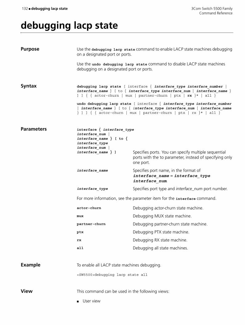
132 ● debugging lacp state 3Com Switch 5500 Family Command Reference
debugging lacp state
Purpose Use the debugging lacp state command to enable LACP state machines debugging on a designated port or ports.
Use the undo debugging lacp state command to disable LACP state machines debugging on a designated port or ports.
Syntax debugging lacp state [ interface { interface_type interface_number | interface_name } [ to { interface_type interface_num | interface_name } ] ] { { actor-churn | mux | partner-churn | ptx | rx }* | all }
undo debugging lacp state [ interface { interface_type interface_number | interface_name } [ to { interface_type interface_num | interface_name } ] ] { { actor-churn | mux | partner-churn | ptx | rx }* | all }
Parameters interface { interface_type interface_num | interface_name } [ to { interface_type interface_num | interface_name } ] Specifies ports. You can specify multiple sequential
ports with the to parameter, instead of specifying only one port.
interface_name Specifies port name, in the format of interface_name = interface_type interface_num.
interface_type Specifies port type and interface_num port number.
For more information, see the parameter item for the interface command.
actor-churn Debugging actor-churn state machine.
mux Debugging MUX state machine.
partner-churn Debugging partner-churn state machine.
ptx Debugging PTX state machine.
rx Debugging RX state machine.
all Debugging all state machines.
Example To enable all LACP state machines debugging.
<SW5500>debugging lacp state all
View This command can be used in the following views:
■ User view

3Com Switch 5500 Family debugging link-aggregation error ● 133 Command Reference
debugging link-aggregation error
Purpose Use the debugging link-aggregation error command to enable link aggregation error debugging.
Use the undo debugging link-aggregation error command to disable link aggregation error debugging.
Syntax debugging link-aggregation error
undo debugging link-aggregation error
Parameters None
Example To enable link aggregation error debugging, enter the following:
<SW5500>debugging link-aggregation error
View This command can be used in the following views:
■ User view

134 ● debugging link-aggregation event 3Com Switch 5500 Family Command Reference
debugging link-aggregation event
Purpose Use the debugging link-aggregation event command to enable link aggregation events debugging.
Use the undo debugging link-aggregation event command to disable link aggregation events debugging.
Syntax debugging link-aggregation event
undo debugging link-aggregation event
Parameters None
Example To enable link aggregation events debugging, enter the following:
<SW5500>debugging link-aggregation event
View This command can be used in the following views:
■ User view
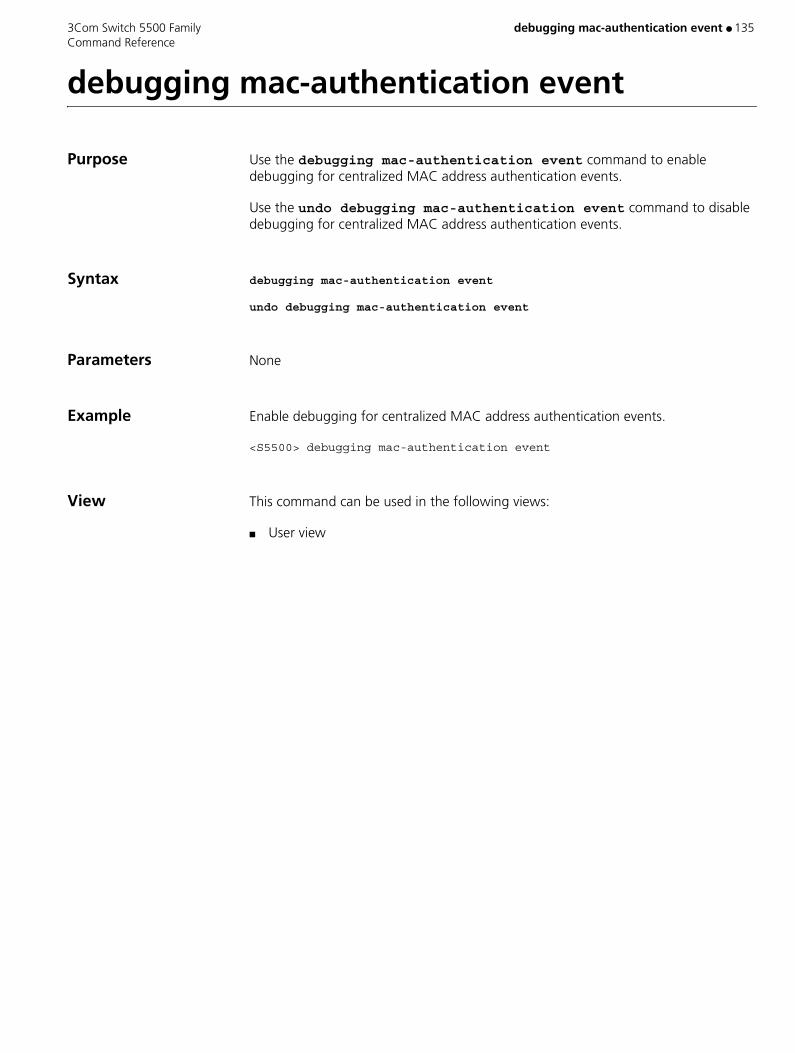
3Com Switch 5500 Family debugging mac-authentication event ● 135 Command Reference
debugging mac-authentication event
Purpose Use the debugging mac-authentication event command to enable debugging for centralized MAC address authentication events.
Use the undo debugging mac-authentication event command to disable debugging for centralized MAC address authentication events.
Syntax debugging mac-authentication event
undo debugging mac-authentication event
Parameters None
Example Enable debugging for centralized MAC address authentication events.
<S5500> debugging mac-authentication event
View This command can be used in the following views:
■ User view
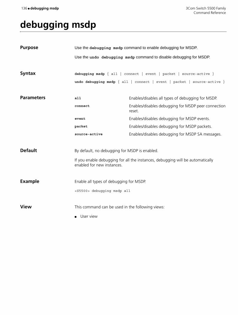
136 ● debugging msdp 3Com Switch 5500 Family Command Reference
debugging msdp
Purpose Use the debugging msdp command to enable debugging for MSDP.
Use the undo debugging msdp command to disable debugging for MSDP.
Syntax debugging msdp { all | connect | event | packet | source-active }
undo debugging msdp { all | connect | event | packet | source-active }
Parameters all Enables/disables all types of debugging for MSDP.
connect Enables/disables debugging for MSDP peer connection reset.
event Enables/disables debugging for MSDP events.
packet Enables/disables debugging for MSDP packets.
source-active Enables/disables debugging for MSDP SA messages.
Default By default, no debugging for MSDP is enabled.
If you enable debugging for all the instances, debugging will be automatically enabled for new instances.
Example Enable all types of debugging for MSDP.
<S5500> debugging msdp all
View This command can be used in the following views:
■ User view
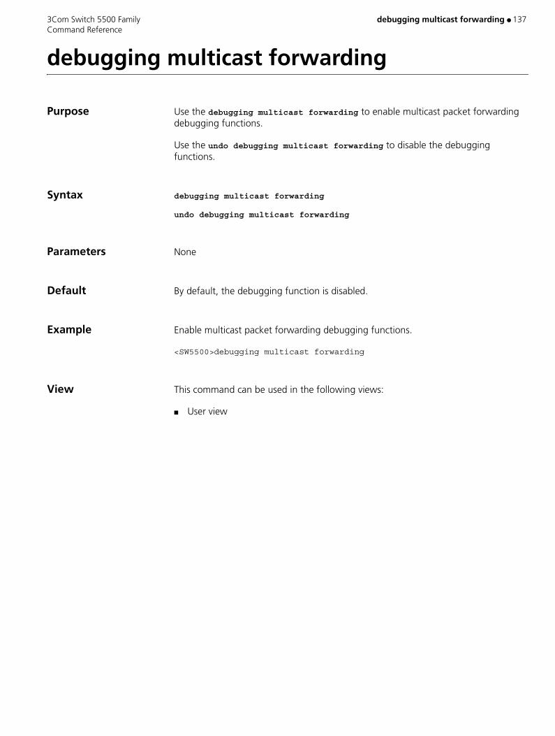
3Com Switch 5500 Family debugging multicast forwarding ● 137 Command Reference
debugging multicast forwarding
Purpose Use the debugging multicast forwarding to enable multicast packet forwarding debugging functions.
Use the undo debugging multicast forwarding to disable the debugging functions.
Syntax debugging multicast forwarding
undo debugging multicast forwarding
Parameters None
Default By default, the debugging function is disabled.
Example Enable multicast packet forwarding debugging functions.
<SW5500>debugging multicast forwarding
View This command can be used in the following views:
■ User view

138 ● debugging multicast kernel-routing 3Com Switch 5500 Family Command Reference
debugging multicast kernel-routing
Purpose Use the debugging multicast kernel-routing to enable multicast kernel routing debugging functions.
Use the undo debugging multicast kernel-routing to disable the debugging functions.
Syntax debugging multicast kernel-routing
undo debugging multicast kernel-routing
Parameters None
Example Enable multicast kernel routing debugging functions.
<SW5500>debugging multicast kernel-routing
View This command can be used in the following views:
■ User view
3Com Switch 5500 Family debugging multicast status-forwarding ● 139 Command Reference
debugging multicast status-forwarding
Purpose Use the debugging multicast status-forwarding to enable multicast forwarding status debugging functions.
Use the undo debugging multicast status-forwarding to disable the debugging functions.
Syntax debugging multicast status-forwarding
undo debugging multicast status-forwarding
Parameters None
Example Enable multicast forwarding status debugging functions.
<SW5500>debugging multicast status-forwarding
View This command can be used in the following views:
■ User view
140 ● debugging ntp-service 3Com Switch 5500 Family Command Reference
debugging ntp-service
Purpose Use the debugging ntp-service command to debug different NTP services.
Use the undo debugging ntp-service command to disable corresponding debugging function.
Syntax debugging ntp-service { access | adjustment | authentication | event | filter | packet | parameter | refclock | selection | synchronization | validity | all }
undo debugging ntp-service { access | adjustment | authentication | event | filter | packet | parameter | refclock | selection | synchronization | validity | all }
Parameters access NTP access control debugging.
adjustment NTP clock adjustment debugging.
all All NTP debugging functions.
authentication NTP authentication debugging.
event NTP event debugging.
filter NTP filter information debugging.
packet NTP packet debugging.
parameter NTP clock parameter debugging.
refclock NTP reference clock debugging.
selection NTP clock selection information debugging.
synchronization NTP clock synchronization information debugging.
validity NTP remote host validity debugging
Default By default, no debugging function is enabled.
Example Enable NTP access control debugging.
<SW5500>debugging ntp-service access
View This command can be used in the following views:
■ User view
3Com Switch 5500 Family debugging pim common ● 141 Command Reference
debugging pim common
Purpose Use the debugging pim common to enable common PIM debugging functions.
Use the undo debugging pim common to disable the debugging functions.
Syntax debugging pim common { all | event | packet | timer }
undo debugging pim common { all | event | packet | timer }
Parameters all All the common debugging information of PIM.
event Debugging information of common PIM event.
packet Debugging information of PIM hello packet.
timer Debugging information of common PIM timer.
Default By default, common PIM debugging functions are disabled.
Example Enable all common PIM debugging functions.
<SW5500>debugging pim common all
View This command can be used in the following views:
■ User view
142 ● debugging pim dm 3Com Switch 5500 Family Command Reference
debugging pim dm
Purpose Use the debugging pim dm to enable PIM-DM debugging functions.
Use the undo debugging pim dm to disable the debugging functions.
Syntax debugging pim dm { alert | all | mrt | timer | warning | { recv | send } { all | assert | graft | graft-ack | join | prune } }
undo debugging pim dm { alert | all | mrt | timer | warning | { recv | send } { all | assert | graft | graft-ack | join | prune } }
Parameters alert Interoperation event debugging information of PIM-DM.
all All the debugging information of PIM-DM.
mrt Debugging information of PIM-DM multicast routing table.
timer Debugging information of PIM-DM timer.
warning Debugging information of PIM-DM warning message.
recv Debugging information of PIM-DM receiving packets.
send Debugging information of PIM-DM sending packets.
all | assert | graft | graft-ack | join | prune Packets type.
Default By default, PIM-DM debugging functions are disabled.
Example Enable all PIM-DM debugging functions
<SW5500>debugging pim dm all
View This command can be used in the following views:
■ User view
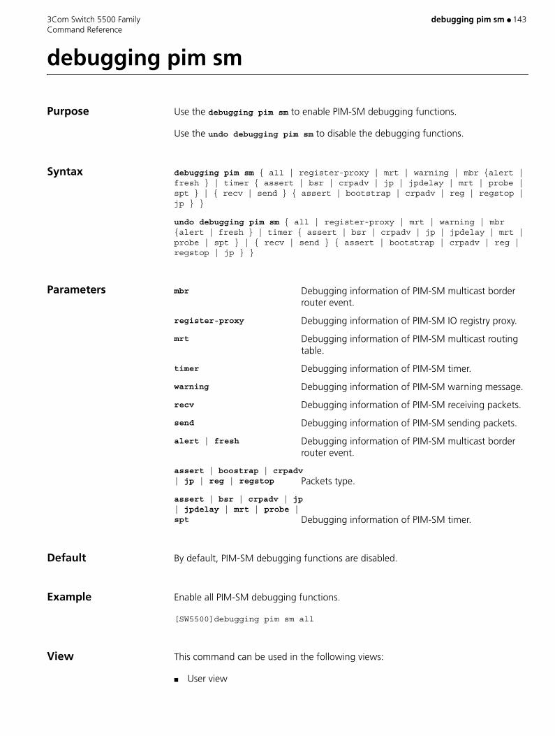
3Com Switch 5500 Family debugging pim sm ● 143 Command Reference
debugging pim sm
Purpose Use the debugging pim sm to enable PIM-SM debugging functions.
Use the undo debugging pim sm to disable the debugging functions.
Syntax debugging pim sm { all | register-proxy | mrt | warning | mbr {alert | fresh } | timer { assert | bsr | crpadv | jp | jpdelay | mrt | probe | spt } | { recv | send } { assert | bootstrap | crpadv | reg | regstop | jp } }
undo debugging pim sm { all | register-proxy | mrt | warning | mbr {alert | fresh } | timer { assert | bsr | crpadv | jp | jpdelay | mrt | probe | spt } | { recv | send } { assert | bootstrap | crpadv | reg | regstop | jp } }
Parameters mbr Debugging information of PIM-SM multicast border router event.
register-proxy Debugging information of PIM-SM IO registry proxy.
mrt Debugging information of PIM-SM multicast routing table.
timer Debugging information of PIM-SM timer.
warning Debugging information of PIM-SM warning message.
recv Debugging information of PIM-SM receiving packets.
send Debugging information of PIM-SM sending packets.
alert | fresh Debugging information of PIM-SM multicast border router event.
assert | boostrap | crpadv | jp | reg | regstop Packets type.
assert | bsr | crpadv | jp | jpdelay | mrt | probe | spt Debugging information of PIM-SM timer.
Default By default, PIM-SM debugging functions are disabled.
Example Enable all PIM-SM debugging functions.
[SW5500]debugging pim sm all
View This command can be used in the following views:
■ User view

144 ● debugging resilient-arp 3Com Switch 5500 Family Command Reference
debugging resilient-arp
Purpose Use the debugging resilient-arp command to enable resilient ARP debugging.
Use the undo debugging resilient-arp command to disable resilient ARP debugging.
Syntax debugging resilient-arp { packet | state | error | all }
undo debugging resilient-arp { packet | state | error | all }
Parameters packet Enter to enable debugging resilient ARP packets.
state Enter to enable debugging resilient ARP state machine.
error Enter to enable debugging resilient ARP errors (including packet errors).
all Enter to enable all resilient ARP debugging.
Default By default, all resilient ARP debugging is disabled.
Example To enable debugging resilient ARP packets, enter the following:
<SW5500>debugging resilient-arp packet
View This command can be used in the following views:
■ User view

3Com Switch 5500 Family debugging ssh server ● 145 Command Reference
debugging ssh server
Purpose Use the debugging ssh server command to send the negotiation process and other information prescribed in SSH 2.0 to the information center as debugging information, and to enable debugging for a single user interface.
Use the undo debugging ssh server command to disable SSH debugging.
Syntax debugging ssh server { VTY vty-num | all }
undo debugging ssh server { VTY vty-num | all }
Parameters vty-num SSH channel to be debugged. It must be within the range of VTY user interface numbers. Valid values are 0 to 4.
all All SSH channels.
Default By default, SSH debugging is not enabled.
Example Enable SSH debugging for the VTY 0 user interface.
<S5500> debugging ssh server vty 0
View This command can be used in the following views:
■ User view
Related Commands ■ ssh server authentication-retries
■ ssh server timeout
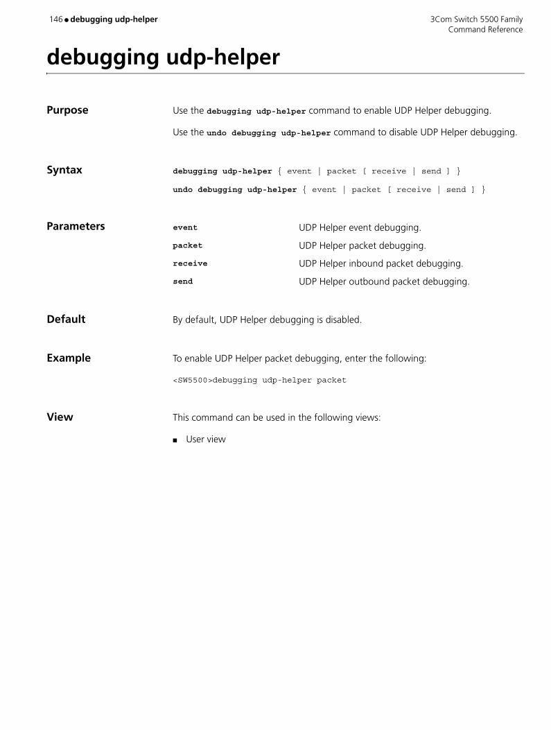
146 ● debugging udp-helper 3Com Switch 5500 Family Command Reference
debugging udp-helper
Purpose Use the debugging udp-helper command to enable UDP Helper debugging.
Use the undo debugging udp-helper command to disable UDP Helper debugging.
Syntax debugging udp-helper { event | packet [ receive | send ] }
undo debugging udp-helper { event | packet [ receive | send ] }
Parameters event UDP Helper event debugging.
packet UDP Helper packet debugging.
receive UDP Helper inbound packet debugging.
send UDP Helper outbound packet debugging.
Default By default, UDP Helper debugging is disabled.
Example To enable UDP Helper packet debugging, enter the following:
<SW5500>debugging udp-helper packet
View This command can be used in the following views:
■ User view
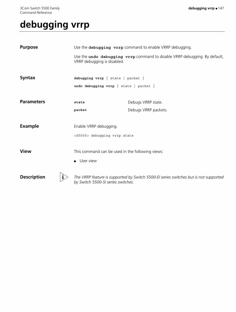
3Com Switch 5500 Family debugging vrrp ● 147 Command Reference
debugging vrrp
Purpose Use the debugging vrrp command to enable VRRP debugging.
Use the undo debugging vrrp command to disable VRRP debugging. By default, VRRP debugging is disabled.
Syntax debugging vrrp { state | packet }
undo debugging vrrp { state | packet }
Parameters state Debugs VRRP state.
packet Debugs VRRP packets.
Example Enable VRRP debugging.
<S5500> debugging vrrp state
View This command can be used in the following views:
■ User view
Description The VRRP feature is supported by Switch 5500-EI series switches but is not supported by Switch 5500-SI series switches.

148 ● debugging webcache 3Com Switch 5500 Family Command Reference
debugging webcache
Purpose Use the debugging webcache command to enable the debugging for Webcache redirection.
Use the undo debugging webcache to disable the debugging for Webcache redirection.
Syntax debugging webcache
undo debugging webcache
Parameters None
Example To enable the debugging for Webcache redirection, enter the following:
<SW5500> debugging webcache
View This command can be used in the following views:
■ User view

3Com Switch 5500 Family default cost ● 149 Command Reference
default cost
Purpose Use the default cost command to configure the default routing cost of an external route imported by OSPF.
Use the undo default cost command to restore the default value of the default routing cost configured for OSPF to import external routes.
Syntax default cost value
undo default cost
Parameters value Specifies the default routing cost of the external route imported by OSPF. Valid values are 0 to 16777214. If not specified, the default value is 1.
Example To specify a default routing cost of 10 for an external route imported by OSPF, enter the following:
<SW5500>system-viewSystem View: return to User View with Ctrl+Z.[SW5500]router id 1.1.1.1[SW5500]ospf[SW5500-ospf-1]default cost 10
View This command can be used in the following views:
■ OSPF view
Description Since OSPF can import external routing information, whose routing cost can influence routing selection and calculation, and propagate it to the entire autonomous system, it is necessary to specify the default routing cost for the protocol to import external routes.

150 ● default-cost 3Com Switch 5500 Family Command Reference
default-cost
Purpose Use the default-cost command to configure the cost of the route transmitted by OSPF to a Stub or NSSA area.
Use the undo default-cost command to restore the default cost of the default route transmitted by OSPF to a Stub or NSSA.
Syntax default-cost value
undo default-cost
Parameters value Specifies the cost value of the default route transmitted by OSPF to a Stub or NSSA area. Valid values are 0 to 16777214. If not specified, the default value is 1.
Example To set area 1 as a Stub area, and to set the cost of the default route transmitted to this Stub area to 60, enter the following commands:
<SW5500>system-viewSystem View: return to User View with Ctrl+Z.[SW5500]router id 1.1.1.1[SW5500]ospf[SW5500-ospf-1]area 1[SW5500-ospf-1-area-0.0.0.1]network 20.0.0.0 0.255.255.255[SW5500-ospf-1-area-0.0.0.1]stub[SW5500-ospf-1-area-0.0.0.1]default-cost 60
View This command can be used in the following views:
■ OSPF Area view
Related Commands ■ nssa
■ stub

3Com Switch 5500 Family default cost ● 151 Command Reference
default cost
Purpose Use the default cost command to set the default routing cost of an imported route.
Use the undo default cost command to restore the default value.
Syntax default cost value
undo default cost
Parameters value Enter the default routing cost. Valid values are 1 to 16. If not specified, the default is 1.
Example To set the default routing cost of the imported route of another routing protocol to 3, enter the following:
<SW5500>system-viewSystem View: return to User View with Ctrl+Z.[SW5500]rip[SW5500-rip]default cost 3
View This command can be used in the following views:
■ RIP view
Description If you do not specify a routing cost when using the import-route command, the default cost you specify here is used.
Related Command import-route

152 ● default interval 3Com Switch 5500 Family Command Reference
default interval
Purpose Use the default interval command to configure the default interval for OSPF to import external routes.
Use the undo default interval command to restore the default value of 1 second.
Syntax default interval seconds
undo default interval
Parameters seconds Specifies the default interval, in seconds, for redistributing external routes. Valid values are 1 to 2147483647. If no value is specified, the default is 1 second.
Example To specify a default interval of 10 seconds for OSPF to import external routes, enter the following:
<SW5500>system-viewSystem View: return to User View with Ctrl+Z.[SW5500]router id 1.1.1.1[SW5500]ospf[SW5500-ospf-1]default interval 10
View This command can be used in the following views:
■ OSPF view
Description Because OSPF can import external routing information and broadcast it to the entire autonomous system, and importing routes can affect the performances of the device (depending on the number of external routes being imported), it is necessary to specify the default interval for the protocol to import external routes.

3Com Switch 5500 Family default limit ● 153 Command Reference
default limit
Purpose Use the default limit command to configure maximum number of allowed imported routes.
Use the undo default limit command to restore the default value.
Syntax default limit routes
undo default limit
Parameters routes Specifies a limit on the number of imported external routes Valid values are 200 to 2147483647. If no value is specified, the default limit is 1000.
Example To specify a limit of 200 imported external routes, enter the following:
<SW5500>system-viewSystem View: return to User View with Ctrl+Z.[SW5500]router id 1.1.1.1[SW5500]ospf[SW5500-ospf-1]default limit 200
View This command can be used in the following views:
■ OSPF view
Description OSPF can import external routing information and advertise them to the whole AS. Importing too many external routes at once can greatly affect the performance of the device.
Related Command default interval
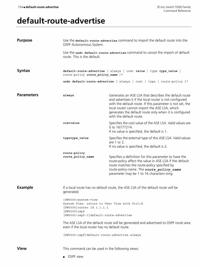
154 ● default-route-advertise 3Com Switch 5500 Family Command Reference
default-route-advertise
Purpose Use the default-route-advertise command to import the default route into the OSPF Autonomous System.
Use the undo default-route-advertise command to cancel the import of default route. This is the default.
Syntax default-route-advertise [ always | cost value | type type_value | route-policy route_policy_name ]*
undo default-route-advertise [ always | cost | type | route-policy ]*
Parameters always Generates an ASE LSA that describes the default route and advertises it if the local router is not configured with the default route. If this parameter is not set, the local router cannot import the ASE LSA, which generates the default route only when it is configured with the default route.
costvalue Specifies the cost value of the ASE LSA. Valid values are 0 to 16777214. If no value is specified, the default is 1.
typetype_value Specifies the external type of this ASE LSA. Valid values are 1 or 2. If no value is specified, the default is 2.
route-policy route_policy_name Specifies a definition for this parameter to have the
route-policy affect the value in ASE LSA if the default route matches the route-policy specified by route-policy-name. The route_policy_name parameter may be 1 to 16 characters long.
Example If a local route has no default route, the ASE LSA of the default route will be generated.
<SW5500>system-viewSystem View: return to User View with Ctrl+Z.[SW5500]router id 1.1.1.1[SW5500]ospf[SW5500-ospf-1]default-route-advertise
The ASE LSA of the default route will be generated and advertised to OSPF route area even if the local router has no default route.
[SW5500-ospf]default-route-advertise always
View This command can be used in the following views:
■ OSPF view

3Com Switch 5500 Family default-route-advertise ● 155 Command Reference
Description The import-route command cannot import the default route. When local router is not configured with default route, the keyword always should be used by ASE LSA to generate default route.
Related Command import-route
156 ● default tag 3Com Switch 5500 Family Command Reference
default tag
Purpose Use the default tag command to configure the default tag of OSPF when it redistributes an external route.
Use the undo default tag command to restore the default tag of OSPF when it redistributes the external route.
Syntax default tag tag
undo default tag
Parameters tag Specifies a tag number. Valid values are 0 to 4294967295.
Example To set a default tag of 10 to OSPF imported external routes, enter the following:
<SW5500>system-viewSystem View: return to User View with Ctrl+Z.[SW5500]router id 1.1.1.1[SW5500]ospf[SW5500-ospf-1]default tag 10
View This command can be used in the following views:
■ OSPF view
Description OSPF requires a default tag when redistributing a route found by other routing protocols.
Related Command default type

3Com Switch 5500 Family default type ● 157 Command Reference
default type
Purpose Use the default type command to configure the default type when OSPF redistributes external routes.
Use the undo default type command to restore the default type.
Syntax default type { 1 | 2 }
undo default type
Parameters 1 Sets the default to external routes of type 1.
2 Sets the default to external routes of type 2. If not specified, the default type is 2.
Example To specify the default type as type 1 when OSPF imports an external route, enter the following:
<SW5500>system-viewSystem View: return to User View with Ctrl+Z.[SW5500]router id 1.1.1.1[SW5500]ospf[SW5500-ospf-1]default type 1
View This command can be used in the following views:
■ OSPF view
Description OSPF requires a default type when redistributing a route found by other routing protocols.
Related Command default tag

158 Command Reference
delete 3Com Switch 5500 Family
delete
Purpose Use the delete command to delete a specified file from the storage device of the switch.
Syntax delete [ / unreserved ] file-path
Parameters /unreserved The file will be deleted permanently if the user chooses this parameter
file-path Path and name of the file you want to delete.
Example Delete the file flash:/test/test.txt
<SW5500>delete flash:/test/test.txtDelete unit1>flash:/test/test.txt?[Y/N]:y%Delete file unit1>flash:/test/test.txt...Done.<SW5500>
View This command can be used in the following views:
■ User view
Description The deleted files are kept in the recycle bin and will not be displayed when you use the dir command. However they will be displayed, using the dir /all command. The files deleted by the delete command can be recovered with the undelete command or deleted permanently from the recycle bin, using the reset recycle-bin command.
If two files with the same name in a directory are deleted, only the latest deleted file will be kept in the recycle bin.

3Com Switch 5500 Family delete
Command Reference 159
delete
Purpose Use the delete command to delete the specified file.
This command is used to delete a file.
Syntax delete remotefile
Parameters remotefile File name.
Example Delete the file temp.c
<SW5500>ftp 1.1.1.1Trying ...Press CTRL+K to abortConnected.220 FTP service ready.User(none):hello331 Password required for hello.Password:230 User logged in.[ftp]delete temp.c250 DELE command successful
View This command can be used in the following views:
■ FTP Client view
160 ● delete 3Com Switch 5500 Family Command Reference
delete
Purpose Use the delete command to delete the specified file from the server.
Syntax delete remote-file
Parameters remote-file Name of a file on the server.
Example Delete file tamp from the server.
sftp-client> delete temp.c
View This command can be used in the following views:
■ SFTP Client view
Description This command has the same function as the remove command.
3Com Switch 5500 Family delete-member ● 161 Command Reference
delete-member
Purpose Use the delete-member command to remove a member from the cluster.
Syntax delete-member member-number
Parameters member-number Number of a member device. Valid values are 1 to 255.
Example Delete the member switch numbered 2 from the cluster.
<aaa_0.S5500>system-viewSystem View: return to User View with Ctrl+Z.[aaa_0.S5500]cluster[aaa_0.S5500-cluster] delete-member 2
View This command can be used in the following views:
■ Cluster view
Description This command can be performed on the management device only. Otherwise, an error message will appear.

162 ● delete static-routes all 3Com Switch 5500 Family Command Reference
delete static-routes all
Purpose Use the delete static-routes all command to delete all the static routes.
Syntax delete static-routes all
Parameters None
Example Delete all the static routes in the router.
<SW5500>system-viewSystem View: return to User View with Ctrl+Z.[SW5500]delete static-routes allAre you sure to delete all the static routes?[Y/N]
View This command can be used in the following views:
■ System view
Description The system requests your confirmation before it deletes all the configured static routes.
Related Commands ■ ip route-static
■ display ip routing-table

3Com Switch 5500 Family description ● 163 Command Reference
description
Purpose Use the description command to enter a description of an Ethernet port.
Use the undo description command to cancel the description.
Syntax description text
undo description
Parameters text Specifies a description of the Ethernet port. The description may be up to 80 characters long.
Default By default, an Ethernet port does not have a description.
Example Set the description of port Ethernet1/0/1 to be lanswitch-interface.
<SW5500>system-viewSystem View: return to User View with Ctrl+Z.[SW5500]interface ethernet 1/0/1[SW5500-Ethernet1/0/1]description lanswitch-interface[SW5500-Ethernet1/0/1]
View This command can be used in the following views:
■ Ethernet Port view

164 ● description 3Com Switch 5500 Family Command Reference
description
Purpose Use the description command to set a description for the current VLAN.
Use the undo description command to cancel the description of current VLAN.
Syntax description string
undo description
Parameters string Specifies a description of the current VLAN, up to a maximum of 32 characters. For a description of a VLAN interface, the maximum is 80 characters.
Example To give VLAN1 the description “RESEARCH”, enter the following:
<SW5500>system-viewSystem View: return to User View with Ctrl+Z.[SW5500]vlan 1[SW5500-vlan1]description RESEARCH[SW5500-vlan1]
View This command can be used in the following views:
■ VLAN view
Description The default description character string of the current VLAN is no description!. The default description character string of the VLAN interface is the interface name, for example, vlan-interface1.
Related Command display vlan

3Com Switch 5500 Family destination-ip ● 165 Command Reference
destination-ip
Purpose Use the destination-ip command to configure the destination IP address of the test.
Use the undo destination-ip command to delete the configured destination IP address.
Syntax destination-ip ip-address
undo destination-ip
Parameters ip-address Destination IP address of the test.
Default By default, no destination IP address is configured for the test.
Example Set the destination IP address of the test in the test group administrator icmp to 10.10.10.10.
<S5500> system-viewSystem View: return to User View with Ctrl+Z.[S5500] remote-ping administrator icmp[S5500-remote-ping-administrator-icmp] destination-ip 10.10.10.10
View This command can be used in the following views:
■ Remote-Ping Test Group view
166 ● detect-group 3Com Switch 5500 Family Command Reference
detect-group
Purpose Use the detect-group command to create a detecting group and enter detecting group view.
Use the undo detect-group command to remove a detecting group.
Syntax detect-group group-number
undo detect-group group-number
Parameters group-number Detecting group number. Valid values are 1 to 50.
Example Create detecting group 10.
<S5500> system-viewSystem View: return to User View with Ctrl+Z.[S5500] detect-group 10[S5500-detect-group-10]
View This command can be used in the following views:
■ System view

3Com Switch 5500 Family detect-list ● 167 Command Reference
detect-list
Purpose Use the detect-list command to specify the IP address to be detected in the detecting group. This command also specifies the order in which the IP addresses in a detecting group are detected.
Use the undo detect-list command to specify to skip a specified IP address when performing auto detect operations.
Syntax detect-list list-number ip address ip-address [ nexthop ip-address ]
undo detect-list list-number ip address ip-address [ nexthop ip-address ]
Parameters list-number Sequence number of the address to be detected. Valid values for this argument are 1 to 10.
ip-address IP address to be detected.
nexthop ip-address Specifies the next hop IP address.
Example Add the IP address of 202.13.1.55 to detecting group 10, with list-number set to 1, the next hop IP address set to 1.1.1.1.
<S5500> system-viewSystem View: return to User View with Ctrl+Z.[S5500] detect-group 10[S5500-detect-group-10] detect-list 1 ip address 202.13.1.55 nexthop 1.1.1.1
View This command can be used in the following views:
■ Detecting Group view
Description When performing auto detect operations, a switch detects the IP addresses by their list-number values in an ascending order. Up to 10 IP addresses can be configured in a detecting group. You can specify how the detecting result is generated using the option command.
Related Command option

168 ● dhcp enable 3Com Switch 5500 Family Command Reference
dhcp enable
Purpose Use the dhcp enable command to enable DHCP.
Use the undo dhcp enable command to disable DHCP.
Syntax dhcp enable
undo dhcp enable
Parameters None
Default By default, DHCP is enabled.
Example Enter system view and enable DHCP, enter the following:
<S5500> system-viewSystem View: return to User View with Ctrl+Z.[S5500] dhcp enable
View This command can be used in the following views:
■ System view
Description You must first enable DHCP before performing other DHCP-related configurations. This configuration is necessary for both DHCP servers and DHCP relays.
This command applies only to the S5500-EI series among Switch 5500-Series Switches.
3Com Switch 5500 Family dhcp relay information enable ● 169 Command Reference
dhcp relay information enable
Purpose Use the dhcp relay information enable command to enable option 82 supporting on a DHCP relay, through which you can enable the DHCP relay to insert option 82 into DHCP request packets sent to a DHCP server.
Use the undo dhcp relay information enable command to disable option 82 supporting on a DHCP relay, through which you can disable the DHCP relay from inserting option 82 into DHCP request packets sent to a DHCP server.
Syntax dhcp relay information enable
undo dhcp relay information enable
Parameters None
Default By default, this function is disabled.
Example Enter system view.
<S5500> system-viewSystem View: return to User View with Ctrl+Z.
Enable option 82 supporting on a DHCP relay.
[S5500] dhcp relay information enable
Disable option 82 supporting on a DHCP relay.
[S5500] undo dhcp relay information enable
View This command can be used in the following views:
■ System view
Related Command dhcp relay information strategy

170 ● dhcp relay information strategy 3Com Switch 5500 Family Command Reference
dhcp relay information strategy
Purpose Use the dhcp relay information strategy command to instruct a DHCP relay to perform specified operations to DHCP request packets that carry option 82.
Use the undo dhcp relay information strategy command to instruct a DHCP relay to perform the default operations to DHCP request packets that carry option 82.
Syntax dhcp relay information strategy { drop | keep | replace }
undo dhcp relay information strategy
Parameters drop Specifies to discard the DHCP request packets that carry option 82.
keep Specifies to remain the DHCP request packets that carry option 82 unchanged.
replace Specifies to replace the option 82 carried by a DHCP request packet with that of the DHCP relay.
Default By default, the DHCP relay replaces the option 82 carried by a DHCP request packet with its own option 82.
Example Enter system view.
<S5500> system-viewSystem View: return to User View with Ctrl+Z.
Instruct the DHCP relay to discard the DHCP request packets that carry option 82.
[S5500] dhcp relay information strategy drop
Instruct the DHCP relay to perform the default operations to DHCP request packets that carry option 82.
[S5500] undo dhcp relay information strategy
View This command can be used in the following views:
■ System view
Related Command dhcp relay information enable

3Com Switch 5500 Family dhcp select global ● 171 Command Reference
dhcp select global
Purpose Use the dhcp select global command to configure the specified interface(s) or all interfaces to operate in global DHCP address pool mode.
Use the undo dhcp select global command to restore the default DHCP packet processing mode.
Syntax VLAN interface view:
dhcp select global
undo dhcp select global
System view:
dhcp select global { interface interface-type interface-number [ to interface-type interface-number ] | all }
undo dhcp select global { interface interface-type interface-number [ to interface-type interface-number ] | all }
Parameters interface interface-type interface-number [ to interface-type interface-number ] Specifies the interface(s) to operate in global address
pool mode. The interface-type and interface-number arguments are the type and number of an interface. The to keyword separates the start and the end of an interface range.
all Specifies all ports to operate in global address pool mode.
Default By default, an interface operates in local DHCP server global address pool mode.
Example Enter system view.
<S5500> system-viewSystem View: return to User View with Ctrl+Z.
Configure all interfaces to operate in global DHCP address pool mode, so that when a DHCP packet is received from a DHCP client through any interface, the DHCP server assigns an IP address in local global DHCP address pools to the DHCP client.
[S5500] dhcp select global all

172 ● dhcp select global 3Com Switch 5500 Family Command Reference
View This command can be used in the following views:
■ System view
■ VLAN Interface view
Description Upon receiving a DHCP packet from a DHCP client through an interface operating in global DHCP address pool mode, the DHCP server chooses an IP address from a global DHCP address pool of the local DHCP server and assigns the address to the DHCP client.
This command applies only to the S5500-EI series among Switch 5500-Series Switches.
3Com Switch 5500 Family dhcp select interface ● 173 Command Reference
dhcp select interface
Purpose Use the dhcp select interface command to configure the specified interface(s) to operate in DHCP interface address pool mode.
Use the undo dhcp select interface command to restore the default DHCP packet processing mode.
Syntax VLAN interface view:
dhcp select interface
undo dhcp select interface
System view:
dhcp select interface { interface interface-type interface-number [ to interface-type interface-number ] | all }
undo dhcp select interface { interface interface-type interface-number [ to interface-type interface-number ] | all }
Parameters interface interface-type interface-number [ to interface-type interface-number ] Specifies the interface(s) to operate in interface
address pool mode.
all Specifies all interfaces to operate in interface address pool mode.
Default By default, an interface operates in local DHCP server global address pool mode.
Example Enter system view.
<S5500> system-viewSystem View: return to User View with Ctrl+Z.
Configure all interfaces to operate in interface DHCP address pool mode, so that when a DHCP packet is received from a DHCP client through any interface, the DHCP server assigns an IP address in the local interface DHCP address pool to the DHCP client.
[S5500] dhcp select interface all
View This command can be used in the following views:
■ System view
■ VLAN Interface view

174 ● dhcp select interface 3Com Switch 5500 Family Command Reference
Description Upon receiving a DHCP packet from a DHCP client through an interface operating in interface address pool mode, the DHCP server chooses an IP address from the interface address pool of the local DHCP server and assigns the address to the DHCP client.
This command applies only to the S5500-EI series among Switch 5500-Series Switches.

3Com Switch 5500 Family dhcp-server ● 175 Command Reference
dhcp-server
Purpose Use the dhcp-server command to map the current VLAN interface to a DHCP server group.
Use the undo dhcp-server command to cancel the mapping.
Syntax dhcp-server groupNo
undo dhcp-server
Parameters groupNo DHCP server group number. Valid values for this argument are 0 to 19.
Examples Enter system view.
<S5500> system-viewSystem View: return to User View with Ctrl+Z.
Enter VLAN 1 interface view.
[S5500] interface vlan-interface 1
Specify that VLAN 1 interface corresponds to DHCP server group 1.
[S5500-Vlan-interface1] dhcp-server 1
View This command can be used in the following views:
■ VLAN Interface view
Related Commands ■ dhcp-server ip
■ display dhcp-server
■ display dhcp-server interface vlan-interface
■ debugging dhcp-relay

176 ● dhcp server detect 3Com Switch 5500 Family Command Reference
dhcp server detect
Purpose Use the dhcp server detect command to enable the private DHCP server detecting function.
Use the undo dhcp server detect command to disable the private DHCP server detecting function.
Syntax dhcp server detect
undo dhcp server detect
Parameters None
Default By default, the private DHCP server detecting function is disabled.
Example Enter system view.
<S5500> system-viewSystem View: return to User View with Ctrl+Z.
Enable the private DHCP server detecting function.
[S5500] dhcp server detect
View This command can be used in the following views:
■ System view
Description With the private DHCP server detecting function enabled, a DHCP server tracks the information (such as the IP addresses and interfaces) of DHCP servers to enable the administrator to detect private DHCP servers in time and take proper measures.
This command applies only to the S5500-EI series among Switch 5500-Series Switches.
3Com Switch 5500 Family dhcp server dns-list ● 177 Command Reference
dhcp server dns-list
Purpose Use the dhcp server dns-list command to configure DNS server IP address(es) for the DHCP address pool(s) of specified interface(s).
Use the undo dhcp server dns-list command to remove the DNS server IP address(es) configured for the DHCP address pool(s) of the specified interface(s).
Syntax VLAN interface view:
dhcp server dns-list ip-address&<1-8>
undo dhcp server dns-list { ip-address | all }
System view:
dhcp server dns-list ip-address&<1-8> { interface interface-type interface-number [ to interface-type interface-number ] | all }
undo dhcp server dns-list { ip-address | all } { interface interface-type interface-number [ to interface-type interface-number ] | all }
Parameters ip-address&<1-8> IP address of a DNS server. &<1-8> means you can provide up to eight DNS server IP addresses. When inputting more than one DNS server IP address, separate two neighboring IP addresses with a space.
interface interface-type interface-number [ to interface-type interface-number ] Specifies the interface(s), through which you can
specify the corresponding interface address pools.
all (In comparison with the ip-address argument) Specifies all DNS server IP addresses.
all (In comparison with the interface keyword) Specifies all interface address pools.
Default By default, no DNS server IP address is configured for a DHCP interface address pool.
Example Enter system view.
<S5500> system-viewSystem View: return to User View with Ctrl+Z.
Enter VLAN 1 interface view.
[S5500] interface Vlan-interface 1

178 ● dhcp server dns-list 3Com Switch 5500 Family Command Reference
Configure the DNS server IP address 1.1.1.254 for the DHCP address pool of the VLAN 1 interface.
[S5500-Vlan-interface1] dhcp server dns-list 1.1.1.254
View This command can be used in the following views:
■ System view
■ VLAN Interface view
Description If you execute the dhcp server dns-list command repeatedly, the new configuration overwrites the previous one.
This command applies only to the S5500-EI series among Switch 5500-Series Switches.
Related Command dns-list

3Com Switch 5500 Family dhcp server domain-name ● 179 Command Reference
dhcp server domain-name
Purpose Use the dhcp server domain-name command to configure a domain name for the DHCP clients whose IP addresses are from the specified interface address pool(s).
Use the undo dhcp server domain-name command to remove the configured domain name.
Syntax VLAN interface view:
dhcp server domain-name domain-name
undo dhcp server domain-name
System view:
dhcp server domain-name domain-name { interface interface-type interface-number [ to interface-type interface-number ] | all }
undo dhcp server domain-name { interface interface-type interface-number [ to interface-type interface-number ] | all }
Parameters domain-name Domain name of the DHCP clients whose IP addresses are from the specified interface address pool(s). This argument consists of a string from 3 to 50 characters long.
interface interface-type interface-number [ to interface-type interface-number ] Specifies the interface(s), through which you can
specify the corresponding interface address pool(s).
all Specifies all interface address pools.
Default By default, no domain name is configured for the DHCP clients.
Example Enter system view.
<S5500> system-viewSystem View: return to User View with Ctrl+Z.
Enter VLAN 1 interface view.
[S5500] interface Vlan-interface 1
Configure the domain name aabbcc.com for the DHCP clients whose IP addresses are from the DHCP address pool of the current VLAN interface.
[S5500-Vlan-interface1] dhcp server domain-name aabbcc.com

180 ● dhcp server domain-name 3Com Switch 5500 Family Command Reference
View This command can be used in the following views:
■ System view
■ VLAN Interface view
Description This command applies only to the S5500-EI series among Switch 5500-Series Switches.
Related Command domain-name

3Com Switch 5500 Family dhcp server expired ● 181 Command Reference
dhcp server expired
Purpose Use the dhcp server expired command to configure the lease time of the IP addresses in the specified interface address pool(s).
Use the undo dhcp server expired command to restore the default lease time.
Syntax VLAN interface view:
dhcp server expired { day day [ hour hour [ minute minute ] ] | unlimited }
undo dhcp server expired
System view:
dhcp server expired { day day [ hour hour [ minute minute ] ] | unlimited } { interface interface-type interface-number [ to interface-type interface-number ] | all }
undo dhcp server expired { interface interface-type interface-number [ to interface-type interface-number ] | all }
Parameters day day Specifies the number of days. Valid values are 0 to 365. If not specified, the default lease time is 1 day.
hour hour Specifies the number of hours. Valid values are 0 to 23.
minute minute Specifies the number of minutes. Valid values are 0 to 59.
unlimited Specifies that the lease time is unlimited. (But actually, the system limits the maximum lease time to about 25 years.)
interface interface-type interface-number [ to interface-type interface-number ] Specifies the interface(s), through which you can
specify the corresponding interface address pool(s).
all Specifies all interface address pools.
Example Enter system view.
<S5500> system-viewSystem View: return to User View with Ctrl+Z.
Set the lease time of the IP addresses in all interface address pools to be 1 day, 2 hours and 3 minutes.
[S5500] dhcp server expired day 1 hour 2 minute 3 all
182 ● dhcp server expired 3Com Switch 5500 Family Command Reference
View This command can be used in the following views:
■ System view
■ VLAN Interface view
Description An IP address is considered to be expired if its lease time is after the year 2106.
This command applies only to the S5500-EI series among Switch 5500-Series Switches.
Related Command expired

3Com Switch 5500 Family dhcp server forbidden-ip ● 183 Command Reference
dhcp server forbidden-ip
Purpose Use the dhcp server forbidden-ip command to forbid the specified IP addresses in a DHCP address pool to be automatically assigned.
Use the undo dhcp server forbidden-ip command to cancel the forbiddance.
Syntax dhcp server forbidden-ip low-ip-address [ high-ip-address ]
undo dhcp server forbidden-ip low-ip-address [ high-ip-address ]
Parameters low-ip-address IP address that is not available for being assigned to DHCP clients automatically (An IP address of this kind is known as a forbidden IP address). This argument also marks the lower end of the range of the forbidden IP addresses.
high-ip-address IP address that is not available for being assigned to DHCP clients. This argument also marks the higher end of the range of the forbidden IP addresses. Note that this argument cannot be less than the low-ip-address argument. If you do not provide this argument, only the IP address specified by the low-ip-address argument is forbidden.
Default By default, all IP addresses in an address pool are allowed to be automatically assigned.
Example Enter system view.
<S5500> system-viewSystem View: return to User View with Ctrl+Z.
Forbid the IP addresses in the range 10.110.1.1 to 10.110.1.63 to be automatically assigned.
[S5500] dhcp server forbidden-ip 10.110.1.1 10.110.1.63
View This command can be used in the following views:
■ System view
Description You will fail to execute the undo dhcp server forbidden-ip command if the specified forbidden IP address range contains any statically bound IP address.
This command applies only to the S5500-EI series among Switch 5500-Series Switches.

184 ● dhcp server forbidden-ip 3Com Switch 5500 Family Command Reference
Related Commands ■ dhcp server ip-pool
■ dhcp server static-bind
■ network
■ static-bind ip-address

3Com Switch 5500 Family dhcp-server ip ● 185 Command Reference
dhcp-server ip
Purpose Use the dhcp-server ip command to configure the DHCP server IP address(es) in a specified DHCP server group.
Use the undo dhcp-server command to remove all DHCP server IP addresses in a DHCP server group.
Syntax dhcp-server groupNo ip ip-address1 [ ipaddress-list ]
undo dhcp-server groupNo
Parameters groupNo DHCP server group number. Valid values are 0 to 19.
ipaddress-1 IP address of DHCP server 1 in the DHCP server group.
ipaddress-list IP addresses of other DHCP servers in the DHCP server group. You can provide up to seven other DHCP sever IP addresses.
Examples Enter system view.
<S5500> system-viewSystem View: return to User View with Ctrl+Z.
Configure three DHCP server IP addresses 1.1.1.1, 2.2.2.2, and 3.3.3.3 for DHCP server group 1, so that this group contains three DHCP servers (server 1, server 2 and server 3).
[S5500] dhcp-server 1 ip 1.1.1.1 2.2.2.2 3.3.3.3
View This command can be used in the following views:
■ System view
Related Commands ■ dhcp-server
■ display dhcp-server
■ debugging dhcp-relay

186 ● dhcp server ip-pool 3Com Switch 5500 Family Command Reference
dhcp server ip-pool
Purpose Use the dhcp server ip-pool command to create a global DHCP address pool and enter DHCP address pool view.
Use the undo dhcp server ip-pool command to remove a specified DHCP address pool.
Syntax dhcp server ip-pool pool-name
undo dhcp server ip-pool pool-name
Parameters pool-name Name of a DHCP address pool, which uniquely identifies the address pool. This argument may be 1 to 35 characters long.
Default By default, no global DHCP address pool is created.
Example Enter system view.
<S5500> system-viewSystem View: return to User View with Ctrl+Z.
Create DHCP address pool 0.
[S5500] dhcp server ip-pool 0[S5500-dhcp-pool-0]
View This command can be used in the following views:
■ System view
Description If the address pool identified by the pool-name argument already exists, this command leads you to DHCP address pool view.
This command applies only to the S5500-EI series among Switch 5500-Series Switches.
Related Command dhcp enable

3Com Switch 5500 Family dhcp server nbns-list ● 187 Command Reference
dhcp server nbns-list
Purpose Use the dhcp server nbns-list command to configure NetBIOS server IP address(es) for the specified DHCP interface address pool(s).
Use the undo dhcp server nbns-list command to remove the NetBIOS server IP address(es) configured for the specified DHCP interface address pool(s).
Syntax VLAN interface view:
dhcp server nbns-list ip-address&<1-8>
undo dhcp server nbns-list { ip-address | all }
System view:
dhcp server nbns-list ip-address&<1-8> { interface interface-type interface-number [ to interface-type interface-number ] | all }
undo dhcp server nbns-list { ip-address | all } { interface interface-type interface-number [ to interface-type interface-number ] | all }
Parameters ip-address&<1-8> IP address of a NetBIOS server. &<1-8> means you can provide up to eight NetBIOS server IP addresses. When inputting more than one NetBIOS server IP address, separate two neighboring IP addresses with a space.
interface interface-type interface-number [ to interface-type interface-number ] Specifies the interface(s), through which you can
specify the corresponding interface address pool(s).
all (In comparison with the ip-address argument) Specifies all NetBIOS server IP addresses.
all (In comparison with the interface keyword) Specifies all interface address pools.
Default By default, no NetBIOS server IP address is configured for a DHCP interface address pool.
Example Enter system view.
<S5500> system-viewSystem View: return to User View with Ctrl+Z.
Configure the NetBIOS server IP address 10.12.1.99 for all the DHCP interface address pools.
[S5500] dhcp server nbns-list 10.12.1.99 all
188 ● dhcp server nbns-list 3Com Switch 5500 Family Command Reference
View This command can be used in the following views:
■ System view
■ VLAN Interface view
Description If you execute the dhcp server nbns-list command repeatedly, the new configuration overwrites the previous one.
This command applies only to the S5500-EI series among Switch 5500-Series Switches.
Related Commands ■ dhcp server netbios-type
■ nbns-list
3Com Switch 5500 Family dhcp server netbios-type ● 189 Command Reference
dhcp server netbios-type
Purpose Use the dhcp server netbios-type command to configure the NetBIOS node type of the DHCP clients whose IP addresses are from the specified interface address pool(s).
Use the undo dhcp server netbios-type command to restore the default NetBIOS node type.
Syntax VLAN interface view:
dhcp server netbios-type { b-node | h-node | m-node | p-node }
undo dhcp server netbios-type
System view:
dhcp server netbios-type { b-node | h-node | m-node | p-node } { interface interface-type interface-number [ to interface-type interface-number ] | all }
undo dhcp server netbios-type { interface interface-type interface-number [ to interface-type interface-number ] | all }
Parameters b-node Specifies the broadcast type. Nodes of this type acquire host name-to-IP address mapping by broadcasting.
p-node Specifies the peer-to-peer type. Nodes of this type acquire host name-to-IP address mapping by communicating with the NetBIOS server.
m-node Specifies the m-typed mixed type. Nodes of this type are p-nodes with some broadcasting features. (The character m here stands for mixed.)
h-node Specifies the hybrid type. Nodes of this type are b-nodes with peer-to-peer communicating features. This node is the default NetBIOS node type.
interface interface-type interface-number [ to interface-type interface-number ] Specifies the interface(s), through which you can
specify the corresponding interface address pools.
all Specifies all interface address pools.
Example Enter system view.
<S5500> system-viewSystem View: return to User View with Ctrl+Z.
190 ● dhcp server netbios-type 3Com Switch 5500 Family Command Reference
Specify p-node as the NetBIOS node type of the DHCP clients whose IP addresses are from the DHCP address pool of VLAN 1 interface.
[S5500] interface vlan-interface 1[S5500-Vlan-interface1] dhcp server netbios-type p-node
View This command can be used in the following views:
■ System view
■ VLAN Interface view
Description This command applies only to the S5500-EI series among Switch 5500-Series Switches.
Related Commands ■ dhcp server nbns-list
■ netbios-type

3Com Switch 5500 Family dhcp server option ● 191 Command Reference
dhcp server option
Purpose Use the dhcp server option command to customize DHCP options for the specified DHCP interface address pool(s).
Use the undo dhcp server option command to remove the customized DHCP options.
Syntax VLAN interface view:
dhcp server option code { ascii ascii-string | hex hex-string&<1-10> | ip-address ip-address&<1-8> }
undo dhcp server option code
System view:
dhcp server option code { ascii ascii-string | hex hex-string&<1-10> | ip-address ip-address&<1-8> } { interface interface-type interface-number [ to interface-type interface-number ] | all }
undo dhcp server option code { interface interface-type interface-number [ to interface-type interface-number ] | all }
Parameters code Customized option number ranging from 2 to 254. Note that this argument cannot be 3, 6, 15, 44, 46, 50 through 55, 57 through 61, 82, or 217.
ascii ascii-string Specifies a string that is of 1 to 63 characters. Note that each character of the string must be an ASCII character.
hex hex-string&<1-10> Specifies strings, each of which comprises 1 to 8 hexadecimal digits. &<1-10> means you can provide up to 10 such strings. When inputting more than one string, separate two neighboring strings with a space. Note that the total number of the hexadecimal digits (spaces not included) cannot exceed 64.
ip-address ip-address&<1-8> Specifies IP addresses. &<1-8> means you can provide
up to eight IP addresses. When inputting more than one IP address, separate two neighboring IP addresses with a space.
interface interface-type interface-number [ to interface-type interface-number ] Specifies the interface(s), through which you can
specify the corresponding interface address pools.
all Specifies all interface address pools.

192 ● dhcp server option 3Com Switch 5500 Family Command Reference
Example Enter system view.
<S5500> system-viewSystem View: return to User View with Ctrl+Z.
Configure option 100 to be 0x11 and 0x22 for all DHCP interface address pools.
[S5500] dhcp server option 100 hex 11 22 all
View This command can be used in the following views:
■ System view
■ VLAN Interface view
Description If you execute the dhcp server option command repeatedly, the new configuration overwrites the previous one.
This command applies only to the S5500-EI series among Switch 5500-Series Switches.
Related Command option

3Com Switch 5500 Family dhcp server ping ● 193 Command Reference
dhcp server ping
Purpose Use the dhcp server ping command to set the maximum number of the ICMP packets a DHCP server sends in a ping test and the maximum response timeout time of each ICMP packet.
Use the undo dhcp server ping command to restore the default settings.
Syntax dhcp server ping { packets number | timeout milliseconds }
undo dhcp server ping { packets | timeout }
Parameters packets number Specifies the number of the packets to be sent in a ping test. The number argument ranges from 0 to 10. A value of 0 means that no packet will be sent. If no value is specified, the default is 2.
timeout milliseconds Specifies the timeout time (in milliseconds) of each packet. The milliseconds argument ranges from 0 to 10,000. If no value is specified, the default is 500.
Example Enter system view.
<S5500> system-viewSystem View: return to User View with Ctrl+Z.
Set the maximum number of the packets the DHCP server sends in a ping test to 10, and the timeout time of each packet to 500 milliseconds.
[S5500] dhcp server ping packets 10
View This command can be used in the following views:
■ System view
Description This command applies only to the S5500-EI series among Switch 5500-Series Switches.
194 ● dhcp server static-bind 3Com Switch 5500 Family Command Reference
dhcp server static-bind
Purpose Use the dhcp server static-bind command to statically bind an IP address of the current address pool to a MAC address.
Use the undo dhcp server static-bind command to cancel an IP-MAC address binding.
Syntax dhcp server static-bind ip-address ip-address mac-address mac-address
undo dhcp server static-bind { ip-address ip-address | mac-address mac-address }
Parameters ip-address IP address to be statically bound. Note that the specified IP address must belong to the same network segment as that of the VLAN interface.
mac-address MAC address to which the IP address is statically bound, in the format of H-H-H.
Default By default, no IP address in an address pool is statically bound.
Example Enter system view.
<S5500> system-viewSystem View: return to User View with Ctrl+Z.
Enter VLAN 1 interface view.
[S5500] interface vlan-interface 1
Statically bind the IP address 10.1.1.1 to the MAC address 0000-e03f-0305. (Assume that the interface address pool of VLAN 1 interface already exists and the IP address belongs to the address pool.)
[S5500-Vlan-interface1] dhcp server static-bind 10.1.1.1 0000-e03f-0305
View This command can be used in the following views:
■ VLAN Interface view
Description This command applies only to the S5500-EI series among Switch 5500-Series Switches.
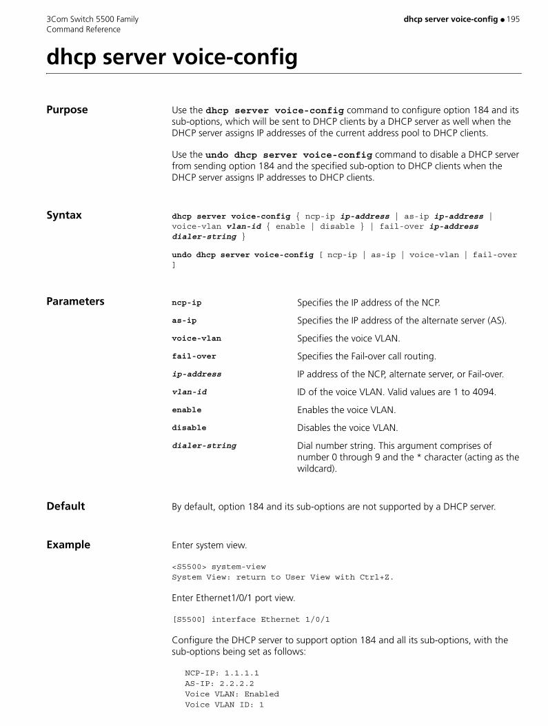
3Com Switch 5500 Family dhcp server voice-config ● 195 Command Reference
dhcp server voice-config
Purpose Use the dhcp server voice-config command to configure option 184 and its sub-options, which will be sent to DHCP clients by a DHCP server as well when the DHCP server assigns IP addresses of the current address pool to DHCP clients.
Use the undo dhcp server voice-config command to disable a DHCP server from sending option 184 and the specified sub-option to DHCP clients when the DHCP server assigns IP addresses to DHCP clients.
Syntax dhcp server voice-config { ncp-ip ip-address | as-ip ip-address | voice-vlan vlan-id { enable | disable } | fail-over ip-address dialer-string }
undo dhcp server voice-config [ ncp-ip | as-ip | voice-vlan | fail-over ]
Parameters ncp-ip Specifies the IP address of the NCP.
as-ip Specifies the IP address of the alternate server (AS).
voice-vlan Specifies the voice VLAN.
fail-over Specifies the Fail-over call routing.
ip-address IP address of the NCP, alternate server, or Fail-over.
vlan-id ID of the voice VLAN. Valid values are 1 to 4094.
enable Enables the voice VLAN.
disable Disables the voice VLAN.
dialer-string Dial number string. This argument comprises of number 0 through 9 and the * character (acting as the wildcard).
Default By default, option 184 and its sub-options are not supported by a DHCP server.
Example Enter system view.
<S5500> system-viewSystem View: return to User View with Ctrl+Z.
Enter Ethernet1/0/1 port view.
[S5500] interface Ethernet 1/0/1
Configure the DHCP server to support option 184 and all its sub-options, with the sub-options being set as follows:
NCP-IP: 1.1.1.1 AS-IP: 2.2.2.2 Voice VLAN: Enabled Voice VLAN ID: 1

196 ● dhcp server voice-config 3Com Switch 5500 Family Command Reference
IP address of Fail-over: 3.3.3.3 Dialer-string: 99*[S5500-Ethernet1/0/1] dhcp select interface[S5500-Ethernet1/0/1] dhcp server voice-config ncp-ip 1.1.1.1[S5500-Ethernet1/0/1] dhcp server voice-config as-ip 2.2.2.2[S5500-Ethernet1/0/1] dhcp server voice-config voice-vlan 1 enable[S5500-Ethernet1/0/1]dhcp server voice-config fail-over 3.3.3.3 99*
View This command can be used in the following views:
■ VLAN Interface view
Description A DHCP server sends Option 184 and the corresponding sub-options to a DHCP client only when the latter requests for option 184.
The NCP-IP sub-option is necessary for all other sub-options. You need to configure the NCP-IP sub-option first to enable other sub-options.
This command applies only to the S5500-EI series among Switch 5500-Series Switches.
Related Command voice-config
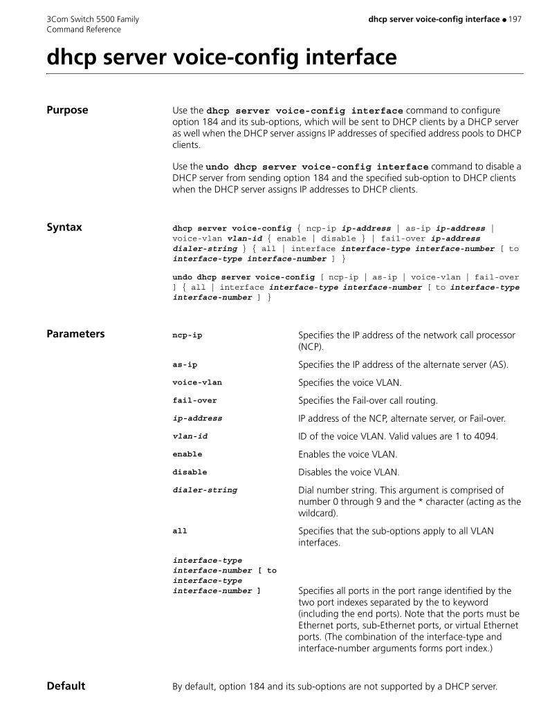
3Com Switch 5500 Family dhcp server voice-config interface ● 197 Command Reference
dhcp server voice-config interface
Purpose Use the dhcp server voice-config interface command to configure option 184 and its sub-options, which will be sent to DHCP clients by a DHCP server as well when the DHCP server assigns IP addresses of specified address pools to DHCP clients.
Use the undo dhcp server voice-config interface command to disable a DHCP server from sending option 184 and the specified sub-option to DHCP clients when the DHCP server assigns IP addresses to DHCP clients.
Syntax dhcp server voice-config { ncp-ip ip-address | as-ip ip-address | voice-vlan vlan-id { enable | disable } | fail-over ip-address dialer-string } { all | interface interface-type interface-number [ to interface-type interface-number ] }
undo dhcp server voice-config [ ncp-ip | as-ip | voice-vlan | fail-over ] { all | interface interface-type interface-number [ to interface-type interface-number ] }
Parameters ncp-ip Specifies the IP address of the network call processor (NCP).
as-ip Specifies the IP address of the alternate server (AS).
voice-vlan Specifies the voice VLAN.
fail-over Specifies the Fail-over call routing.
ip-address IP address of the NCP, alternate server, or Fail-over.
vlan-id ID of the voice VLAN. Valid values are 1 to 4094.
enable Enables the voice VLAN.
disable Disables the voice VLAN.
dialer-string Dial number string. This argument is comprised of number 0 through 9 and the * character (acting as the wildcard).
all Specifies that the sub-options apply to all VLAN interfaces.
interface-type interface-number [ to interface-type interface-number ] Specifies all ports in the port range identified by the
two port indexes separated by the to keyword (including the end ports). Note that the ports must be Ethernet ports, sub-Ethernet ports, or virtual Ethernet ports. (The combination of the interface-type and interface-number arguments forms port index.)
Default By default, option 184 and its sub-options are not supported by a DHCP server.
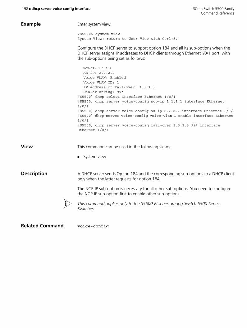
198 ● dhcp server voice-config interface 3Com Switch 5500 Family Command Reference
Example Enter system view.
<S5500> system-viewSystem View: return to User View with Ctrl+Z.
Configure the DHCP server to support option 184 and all its sub-options when the DHCP server assigns IP addresses to DHCP clients through Ethernet1/0/1 port, with the sub-options being set as follows:
NCP-IP: 1.1.1.1
AS-IP: 2.2.2.2 Voice VLAN: Enabled Voice VLAN ID: 1 IP address of Fail-over: 3.3.3.3 Dialer-string: 99*[S5500] dhcp select interface Ethernet 1/0/1[S5500] dhcp server voice-config ncp-ip 1.1.1.1 interface Ethernet 1/0/1[S5500] dhcp server voice-config as-ip 2.2.2.2 interface Ethernet 1/0/1[S5500] dhcp server voice-config voice-vlan 1 enable interface Ethernet 1/0/1[S5500] dhcp server voice-config fail-over 3.3.3.3 99* interface Ethernet 1/0/1
View This command can be used in the following views:
■ System view
Description A DHCP server sends Option 184 and the corresponding sub-options to a DHCP client only when the latter requests for option 184.
The NCP-IP sub-option is necessary for all other sub-options. You need to configure the NCP-IP sub-option first to enable other sub-options.
This command applies only to the S5500-EI series among Switch 5500-Series Switches.
Related Command voice-config
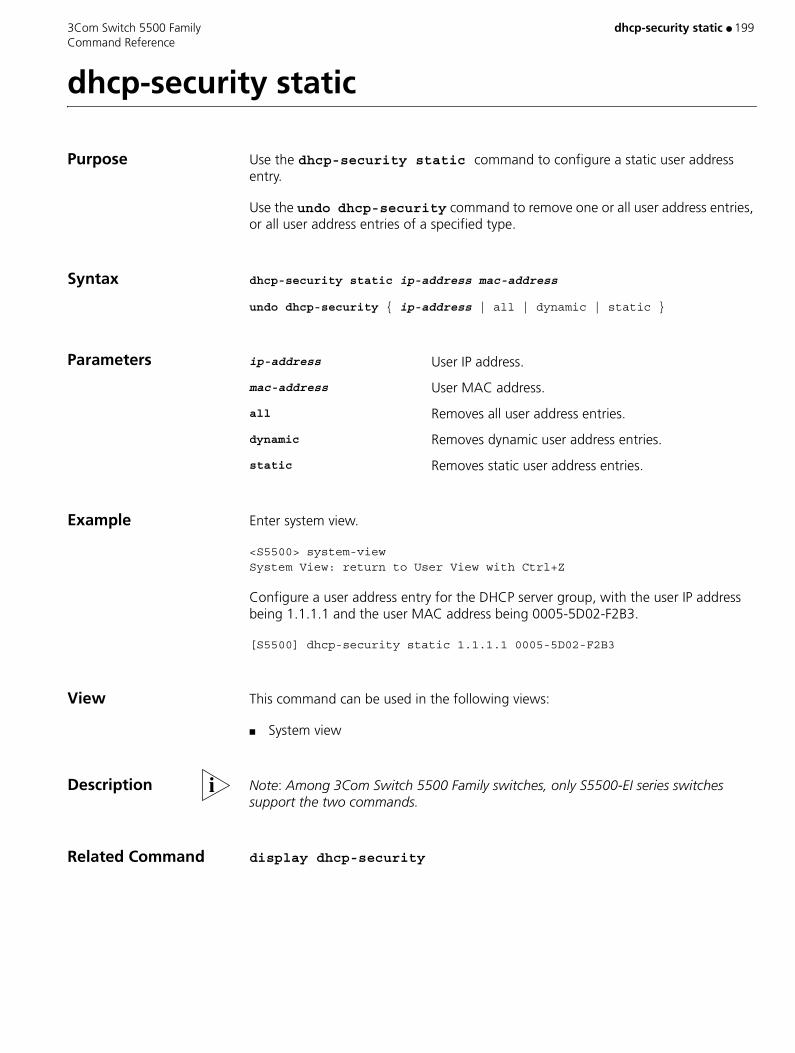
3Com Switch 5500 Family dhcp-security static ● 199 Command Reference
dhcp-security static
Purpose Use the dhcp-security static command to configure a static user address entry.
Use the undo dhcp-security command to remove one or all user address entries, or all user address entries of a specified type.
Syntax dhcp-security static ip-address mac-address
undo dhcp-security { ip-address | all | dynamic | static }
Parameters ip-address User IP address.
mac-address User MAC address.
all Removes all user address entries.
dynamic Removes dynamic user address entries.
static Removes static user address entries.
Example Enter system view.
<S5500> system-viewSystem View: return to User View with Ctrl+Z
Configure a user address entry for the DHCP server group, with the user IP address being 1.1.1.1 and the user MAC address being 0005-5D02-F2B3.
[S5500] dhcp-security static 1.1.1.1 0005-5D02-F2B3
View This command can be used in the following views:
■ System view
Description Note: Among 3Com Switch 5500 Family switches, only S5500-EI series switches support the two commands.
Related Command display dhcp-security
200 ● dhcp-security tracker 3Com Switch 5500 Family Command Reference
dhcp-security tracker
Purpose Use the dhcp-security tracker command to set the interval to update DHCP security entries.
Use the undo dhcp-security tracker command to cancel the configuration.
Syntax dhcp-security tracker { interval | auto }
undo dhcp-security tracker [ interval ]
Parameters interval Interval (in seconds) to update DHCP security entries. Valid values are 1 to 120 seconds.
auto Specifies that the interval to update DHCP security entries is automatically determined by the number of the DHCP security entries. A larger number corresponds to a longer interval.
Default By default, the update interval is determined by the number of the DHCP security entries.
Example Enter system view.
<S5500> system-viewSystem View: return to User View with Ctrl+Z.
Set the interval to update dynamic address entries to 60 seconds.
[S5500] dhcp-security tracker 60
View This command can be used in the following views:
■ System view
Description Note:
Switch 5500 Sl-series switches do not support these two commands.

3Com Switch 5500 Family dhcp-snooping ● 201 Command Reference
dhcp-snooping
Purpose Use the dhcp-snooping command to enable the DHCP snooping function, so as to allow the switch to listen to the DHCP broadcast packets.
Use the undo dhcp-snooping command to disable the DHCP snooping function.
Syntax dhcp-snooping
undo dhcp-snooping
Parameters None
Default By default, the DHCP snooping function is disabled.
Example Enter system view.
<S5500> system-viewSystem View: return to User View with Ctrl+Z.
Enable the DHCP snooping function.
[S5500] dhcp-snooping
View This command can be used in the following views:
■ System view
Related Command display dhcp-snooping
202 ● dhcp-snooping trust 3Com Switch 5500 Family Command Reference
dhcp-snooping trust
Purpose Use the dhcp-snooping trust command to set an Ethernet port to a trusted port.
Use the undo dhcp-snooping trust command to restore an Ethernet port to an untrusted port.
Syntax dhcp-snooping trust
undo dhcp-snooping trust
Parameters None
Example Enter system view.
<S5500> system-viewSystem View: return to User View with Ctrl+Z.
Set the Ethernet1/0/1 port to a trusted port.
[S5500-Ethernet1/0/1] dhcp-snooping trust
View This command can be used in the following views:
■ Ethernet Port view
Description DHCP snooping security allow you to set a port to a trusted port or an untrusted port, so that DHCP clients can obtain IP addresses from only valid DHCP servers.
■ Trusted ports can be used to connect DHCP servers or ports of other switches. Untrusted ports can be used to connect DHCP clients or networks.
■ Trusted ports forward any received DHCP packets to ensure that DHCP clients can obtain IP addresses from valid DHCP servers. Untrusted ports discard the DHCP-ACK and DHCP-OFF responses received from DHCP servers.
■ By default, all the ports of a switch are untrusted ports.
Related Command display dhcp-snooping trust
3Com Switch 5500 Family dir
dir
Purpose Use the dir command to display the information about the specified file or directory in the storage device of the Switch.
Syntax dir [ /all ] [ file-path ]
Parameters /all Display all the files (including the deleted ones).
file-path File or directory name to be displayed. The file-path parameter supports “*” matching. For example, using dir *.txt will display all the files with the extension txt in the current directory.
dir without any parameters will display the file information in the current directory.
Example Display the information for file flash:/test/test.txt
<SW5500>dir flash:/test/test.txtDirectory of unit1>flash:/test/test.txt1 -rw- 248 Aug 29 2000 17:49:36 text.txt20578304 bytes total (3104544 bytes free)
Display information for directory flash:/test/
<SW5500>dir flash:/test/
Directory of unit1>flash:/test/
1 -rw- 248 Aug 29 2000 17:49:36 test.txt20578304 bytes total (3104544 bytes free)
Display all of the files with names starting with "t" in directory flash:/test/
<SW5500>dir flash:/test/t*Directory of unit1>flash:/test/t*1 -rw- 248 Aug 29 2000 17:49:36 test.txt20578304 bytes total (3104544 bytes free)
Display information about all of the files (including the deleted files) in directory flash:/test/
<SW5500>dir /all flash:/test/Directory of unit1>flash:/test/1 -rw- 248 Aug 29 2000 17:49:36 text.txt20578304 bytes total (3104544 bytes free)
Command Reference 203

dir 3Com Switch 5500 Family
Display information about all of the files (including the deleted files) with names starting with "t" in flash:/test/
<SW5500>dir /all flash:/test/t*Directory of unit1>flash:/test/t*1 -rw- 248 Aug 29 2000 17:49:36 text.txt20578304 bytes total (3104544 bytes free)
View This command can be used in the following views:
■ User view
204 Command Reference
3Com Switch 5500 Family dir ● 205 Command Reference
dir
Purpose Use the dir command to display the files in the specified directory.
Syntax dir [ remote-path ]
Parameters remote-path Name of the intended directory.
If the remote-path argument is not specified, the files in the current directory are displayed.
Example Display the files in directory flash:/.
sftp-client> dir flash:/-rwxrwxrwx 1 noone nogroup 1759 Aug 23 06:52 vrpcfg.cfg-rwxrwxrwx 1 noone nogroup 225 Aug 24 08:01 pubkey2-rwxrwxrwx 1 noone nogroup 283 Aug 24 07:39 pubkey1-rwxrwxrwx 1 noone nogroup 225 Sep 28 08:28 pub1drwxrwxrwx 1 noone nogroup 0 Sep 28 08:24 new1drwxrwxrwx 1 noone nogroup 0 Sep 28 08:18 new2-rwxrwxrwx 1 noone nogroup 225 Sep 28 08:30 pub2
View This command can be used in the following views:
■ SFTP Client view
Description This command has the same function as the ls command.
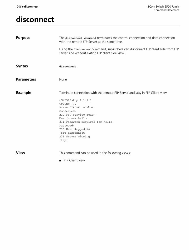
206 ● disconnect 3Com Switch 5500 Family Command Reference
disconnect
Purpose The disconnect command terminates the control connection and data connection with the remote FTP Server at the same time.
Using the disconnect command, subscribers can disconnect FTP client side from FTP server side without exiting FTP client side view.
Syntax disconnect
Parameters None
Example Terminate connection with the remote FTP Server and stay in FTP Client view.
<SW5500>ftp 1.1.1.1Trying ...Press CTRL+K to abortConnected.220 FTP service ready.User(none):hello331 Password required for hello.Password:230 User logged in.[ftp]disconnect221 Server closing[ftp]
View This command can be used in the following views:
■ FTP Client view

3Com Switch 5500 Family display acl ● 207 Command Reference
display acl
Purpose Use the display acl command to view the detailed configuration information about the ACL, including every rule, sequence number and the number and byte number of the packets matched with this rule.
Syntax display acl { all | acl-number }
Parameters all Displays all ACLs.
acl-number Specifies the sequence number of the ACL to be displayed. Valid values are 2000 to 5999.
Example Display the content of all the ACLs.
<SW5500>display acl allBasic acl 2000, 0 rule,match-order is autoAcl’s step is 1
Advanced ACL 3000, 1 ruleAcl's step is 1 rule 1 permit ip (0 times matched)
View This command can be used in the following views:
■ Any view
Description The matched times displayed by this command are software matched times, namely, the matched times of the ACL to be processed by the Switch CPU. You can use the traffic-statistic command to calculate the matched times of hardware during packet-forwarding
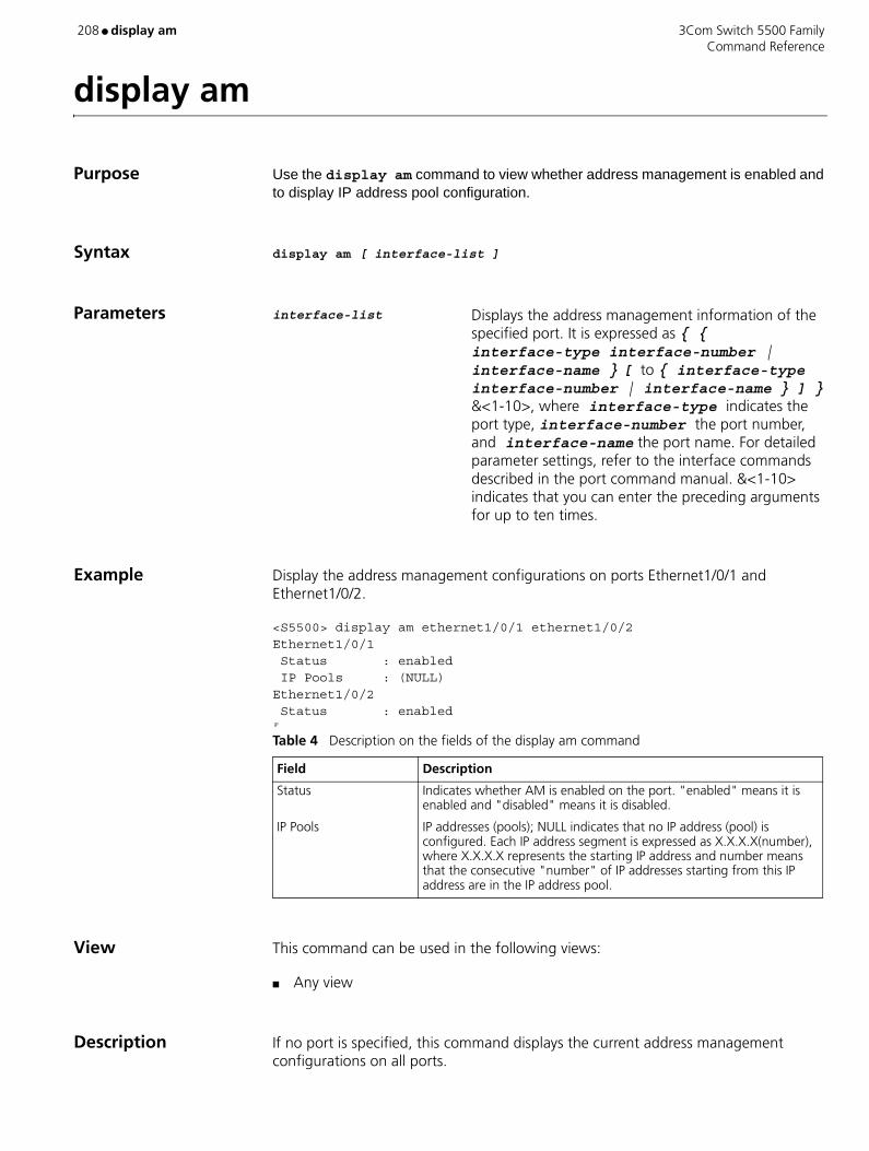
208 ● display am 3Com Switch 5500 Family Command Reference
display am
Purpose Use the display am command to view whether address management is enabled and to display IP address pool configuration.
Syntax display am [ interface-list ]
Parameters interface-list Displays the address management information of the specified port. It is expressed as { { interface-type interface-number | interface-name } [ to { interface-type interface-number | interface-name } ] } &<1-10>, where interface-type indicates the port type, interface-number the port number, and interface-name the port name. For detailed parameter settings, refer to the interface commands described in the port command manual. &<1-10> indicates that you can enter the preceding arguments for up to ten times.
Example Display the address management configurations on ports Ethernet1/0/1 and Ethernet1/0/2.
<S5500> display am ethernet1/0/1 ethernet1/0/2Ethernet1/0/1 Status : enabled IP Pools : (NULL)Ethernet1/0/2 Status : enabled IP
View This command can be used in the following views:
■ Any view
Description If no port is specified, this command displays the current address management configurations on all ports.
Table 4 Description on the fields of the display am command
Field Description
Status Indicates whether AM is enabled on the port. "enabled" means it is enabled and "disabled" means it is disabled.
IP Pools IP addresses (pools); NULL indicates that no IP address (pool) is configured. Each IP address segment is expressed as X.X.X.X(number), where X.X.X.X represents the starting IP address and number means that the consecutive "number" of IP addresses starting from this IP address are in the IP address pool.
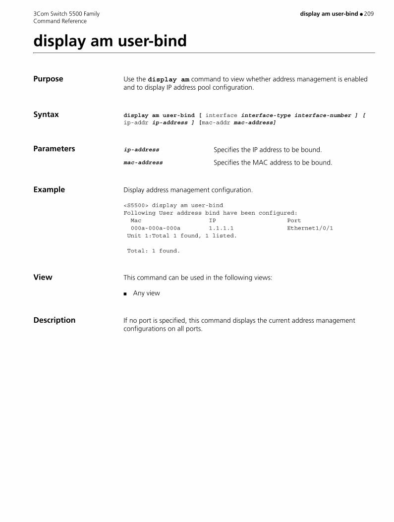
3Com Switch 5500 Family display am user-bind ● 209 Command Reference
display am user-bind
Purpose Use the display am command to view whether address management is enabled and to display IP address pool configuration.
Syntax display am user-bind [ interface interface-type interface-number ] [ ip-addr ip-address ] [mac-addr mac-address]
Parameters ip-address Specifies the IP address to be bound.
mac-address Specifies the MAC address to be bound.
Example Display address management configuration.
<S5500> display am user-bindFollowing User address bind have been configured: Mac IP Port 000a-000a-000a 1.1.1.1 Ethernet1/0/1 Unit 1:Total 1 found, 1 listed.
Total: 1 found.
View This command can be used in the following views:
■ Any view
Description If no port is specified, this command displays the current address management configurations on all ports.

210 ● display arp 3Com Switch 5500 Family Command Reference
display arp
Purpose Use the display arp command to display the ARP mapping table entries by entry type, or by a specified IP address.
Syntax display arp [ ip-address | [ dynamic | static ] [ | { begin | include | exclude } text ]]
Parameters dynamic Displays the dynamic ARP entries in the ARP mapping table.
static Displays the static ARP entries in the ARP mapping table.
begin Specifies to start displaying from the first ARP entry that contains the specified character string "text".
include Displays only the ARP entries that contain the specified character string "text".
exclude Displays only the ARP entries that do not contain the specified character string "text".
text Displays the ARP entries that contain this user-defined character string.
Example To display all ARP entries in the mapping table, enter the following:
<SW5500>display arpType: S-Static D-DynamicIP Address MAC Address VLAN ID Port Name / AL ID Aging Type161.71.61.20 0020-9c08-e774 1 Ethernet2/0/6 20 D
--- 1 entry found ---<SW5500>
View This command can be used in the following views:
■ Any view
Related Commands ■ arp static
Table 5 Output Description of the display arp command
Field Description
IP Address IP address of the ARP mapping entry
MAC Address MAC address of the ARP mapping entry
VLAN ID VLAN to which the static ARP entry belongs
Port Name Port to which the static ARP entry belongs
Aging Aging time of dynamic ARP entry in minutes
Type Type of ARP entry

3Com Switch 5500 Family display arp ● 211 Command Reference
■ reset arp

212 ● display arp timer aging 3Com Switch 5500 Family Command Reference
display arp timer aging
Purpose Use the display arp timer aging command to view the current setting of the dynamic ARP aging timer.
Syntax display arp timer aging
Parameters None
Example To display the current setting of the dynamic ARP aging timer, enter the following:
<SW5500>system-viewSystem View: return to User View with Ctrl+Z.[SW5500] display arp timer aging
The information displays in the following format:Current ARP aging time is 20 minute(s) (default) [SW5500]
View This command can be used in the following views:
■ Any view
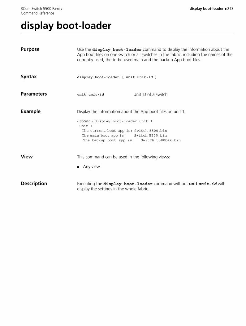
3Com Switch 5500 Family display boot-loader ● 213 Command Reference
display boot-loader
Purpose Use the display boot-loader command to display the information about the App boot files on one switch or all switches in the fabric, including the names of the currently used, the to-be-used main and the backup App boot files.
Syntax display boot-loader [ unit unit-id ]
Parameters unit unit-id Unit ID of a switch.
Example Display the information about the App boot files on unit 1.
<S5500> display boot-loader unit 1 Unit 1 The current boot app is: Switch 5500.bin The main boot app is: Switch 5500.bin
The backup boot app is: Switch 5500bak.bin
View This command can be used in the following views:
■ Any view
Description Executing the display boot-loader command without unit unit-id will display the settings in the whole fabric.
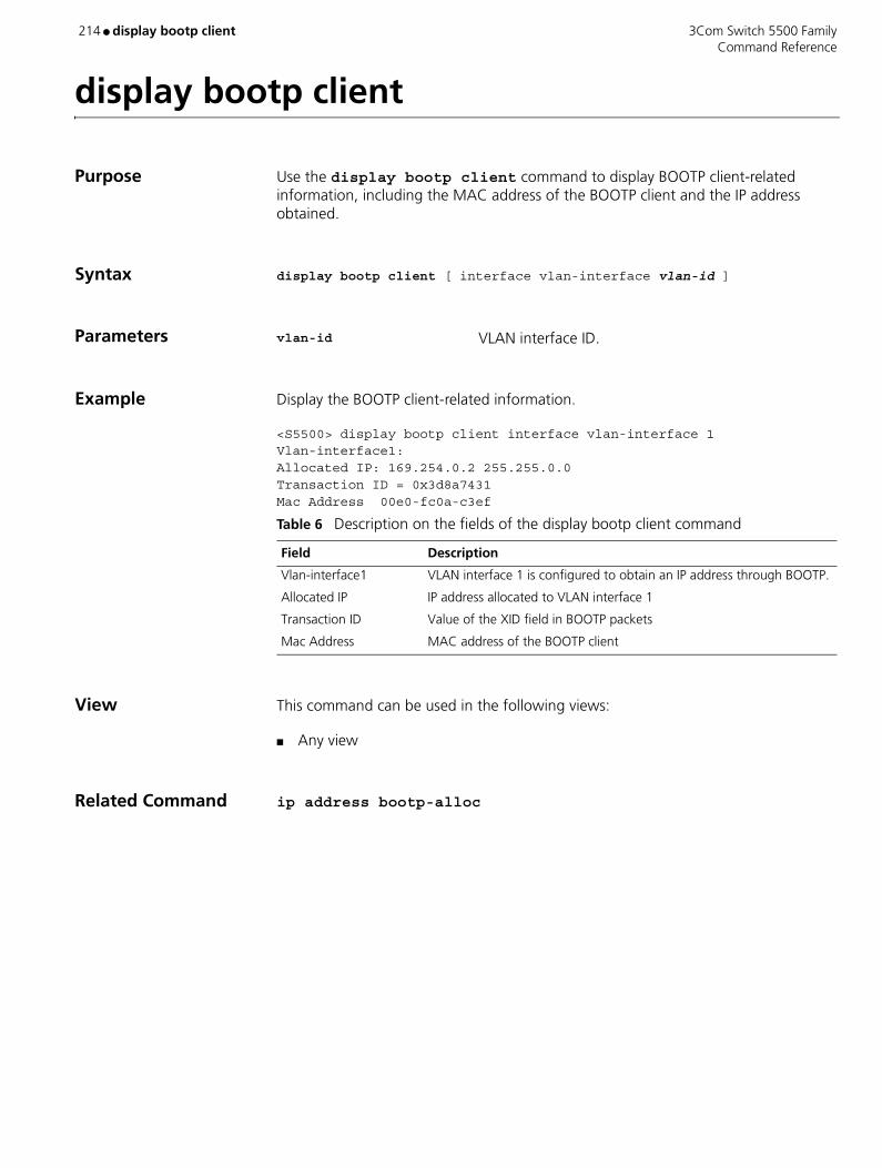
214 ● display bootp client 3Com Switch 5500 Family Command Reference
display bootp client
Purpose Use the display bootp client command to display BOOTP client-related information, including the MAC address of the BOOTP client and the IP address obtained.
Syntax display bootp client [ interface vlan-interface vlan-id ]
Parameters vlan-id VLAN interface ID.
Example Display the BOOTP client-related information.
<S5500> display bootp client interface vlan-interface 1Vlan-interface1:Allocated IP: 169.254.0.2 255.255.0.0Transaction ID = 0x3d8a7431Mac Address 00e0-fc0a-c3ef
View This command can be used in the following views:
■ Any view
Related Command ip address bootp-alloc
Table 6 Description on the fields of the display bootp client command
Field Description
Vlan-interface1 VLAN interface 1 is configured to obtain an IP address through BOOTP.
Allocated IP IP address allocated to VLAN interface 1
Transaction ID Value of the XID field in BOOTP packets
Mac Address MAC address of the BOOTP client
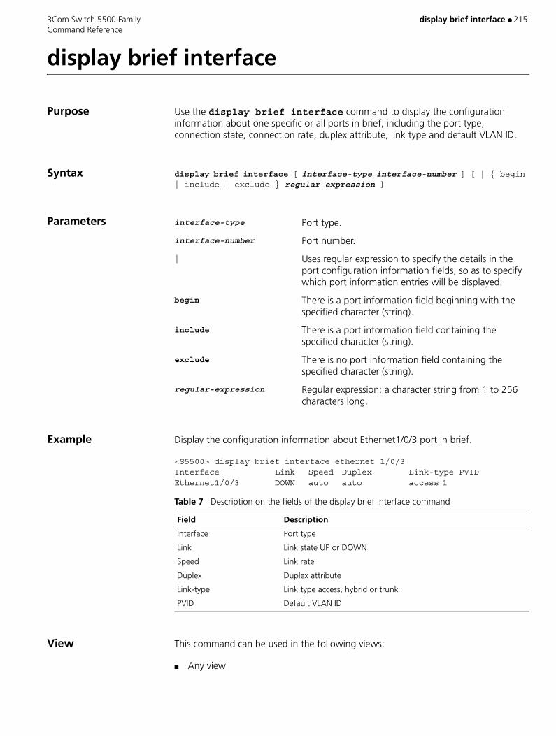
3Com Switch 5500 Family display brief interface ● 215 Command Reference
display brief interface
Purpose Use the display brief interface command to display the configuration information about one specific or all ports in brief, including the port type, connection state, connection rate, duplex attribute, link type and default VLAN ID.
Syntax display brief interface [ interface-type interface-number ] [ | { begin | include | exclude } regular-expression ]
Parameters interface-type Port type.
interface-number Port number.
| Uses regular expression to specify the details in the port configuration information fields, so as to specify which port information entries will be displayed.
begin There is a port information field beginning with the specified character (string).
include There is a port information field containing the specified character (string).
exclude There is no port information field containing the specified character (string).
regular-expression Regular expression; a character string from 1 to 256 characters long.
Example Display the configuration information about Ethernet1/0/3 port in brief.
<S5500> display brief interface ethernet 1/0/3Interface Link Speed Duplex Link-type PVID Ethernet1/0/3 DOWN auto auto access 1
View This command can be used in the following views:
■ Any view
Table 7 Description on the fields of the display brief interface command
Field Description
Interface Port type
Link Link state UP or DOWN
Speed Link rate
Duplex Duplex attribute
Link-type Link type access, hybrid or trunk
PVID Default VLAN ID

216 ● display brief interface 3Com Switch 5500 Family Command Reference
Description This command functions similarly to the display interface command but displays the port information in brief.
Currently, for a non-Ethernet port, the system only displays its connection state and displays "--" in other configuration information fields.
Related Command display interface
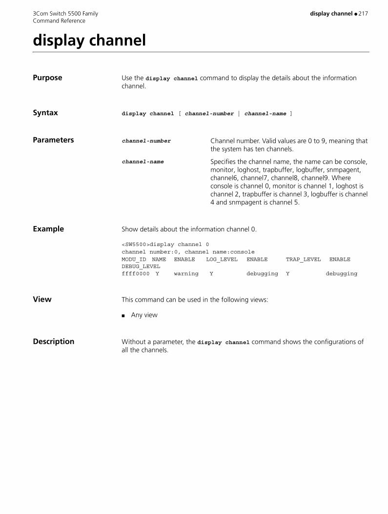
3Com Switch 5500 Family display channel ● 217 Command Reference
display channel
Purpose Use the display channel command to display the details about the information channel.
Syntax display channel [ channel-number | channel-name ]
Parameters channel-number Channel number. Valid values are 0 to 9, meaning that the system has ten channels.
channel-name Specifies the channel name, the name can be console, monitor, loghost, trapbuffer, logbuffer, snmpagent, channel6, channel7, channel8, channel9. Where console is channel 0, monitor is channel 1, loghost is channel 2, trapbuffer is channel 3, logbuffer is channel 4 and snmpagent is channel 5.
Example Show details about the information channel 0.
<SW5500>display channel 0channel number:0, channel name:consoleMODU_ID NAME ENABLE LOG_LEVEL ENABLE TRAP_LEVEL ENABLE DEBUG_LEVEL ffff0000 Y warning Y debugging Y debugging
View This command can be used in the following views:
■ Any view
Description Without a parameter, the display channel command shows the configurations of all the channels.
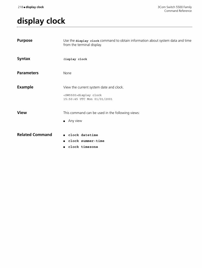
218 ● display clock 3Com Switch 5500 Family Command Reference
display clock
Purpose Use the display clock command to obtain information about system data and time from the terminal display.
Syntax display clock
Parameters None
Example View the current system date and clock.
<SW5500>display clock15:50:45 UTC Mon 01/01/2001
View This command can be used in the following views:
■ Any view
Related Command ■ clock datetime
■ clock summer-time
■ clock timezone

3Com Switch 5500 Family display cluster ● 219 Command Reference
display cluster
Purpose Use the display cluster command to display the state and basic configuration information of the cluster that contains the current switch.
Syntax display cluster
Parameters None
Example Display cluster information on the management device.
<aaa_0.S5500-cluster> display clusterCluster name:"aaa"Role:AdministratorManagement-vlan:100
Handshake timer:10 secHandshake hold-time:60 secIP-Pool:20.1.1.1/24cluster-mac:0180-c200-000aNo logging host configuredNo SNMP host configuredNo FTP server configuredNo TFTP server configured
3 member(s) in the cluster, and 0 of them down.
Display cluster information on the member device.
[aaa_2.5500-3] display clusterCluster name:"aaa"Role:MemberMember number:2Management-vlan:100
cluster-mac:0180-c200-000aHandshake timer:10 secHandshake hold-time:60 sec
Administrator device mac address:00e0-fc00-3901Administrator status:Up
Table 1 Description of cluster status and statistics
Field Description
Cluster name Name of the cluster
Role Role of the cluster member
Member number Number of the cluster member
Handshake timer Value of handshake timer
Handshake hold-time Value of handshake hold-time
Administrator device mac address
MAC address of management device
Administrator status Status of the management device

220 ● display cluster 3Com Switch 5500 Family Command Reference
View This command can be used in the following views:
■ Any view
Description This command can be performed on both the management device and member device, but the displays are different.
On the member device, displayed information includes the cluster name, member serial number and management device information, including the MAC address, state, holdtime and packet interval.
On the management device, displayed information includes the cluster name, total member number and management device information, including the state, holdtime and packet interval.
Using this command on a device that is not in any cluster will result in error message.

3Com Switch 5500 Family display cluster candidates ● 221 Command Reference
display cluster candidates
Purpose Use the display cluster candidates command to display candidate devices of a cluster.
Syntax display cluster candidates [ mac-address H-H-H | verbose ]
Parameters mac-address H-H-H MAC address of the candidate device.
verbose Displays the detailed information about the candidate device.
Example Display a list of all candidate devices.
<aaa_0.S5500-cluster> display cluster candidatesMAC HOP IP PLATFORM5500-0000-3334 2 16.1.1.11/24 S550000e0-fc00-3190 1 16.1.1.1/24 S5500
Table 8 Description of candidate list information
Display the detailed information about the specified candidate device.
<aaa_0.S5500-cluster> display cluster candidates mac-address 00e0-fc00-3190Hostname : aaa_1.5500MAC : 00e0-fc00-3190Hop : 1Platform : S5500IP : 16.1.1.1/24
Display the detailed information about all the candidate devices.
[aaa_0.S5500-cluster]display cluster candidates verbose
Hostname : S5500MAC : 5500-0000-3334Hop : 2Platform : S5500IP : 16.1.1.11/24
Hostname : 5500-3MAC : 00e0-fc00-3190Hop : 1Platform : S5500IP : 16.1.1.1/24
Field Description
MAC MAC address
Hop Hops to the management device
IP IP address
Platform Platform of the candidate device
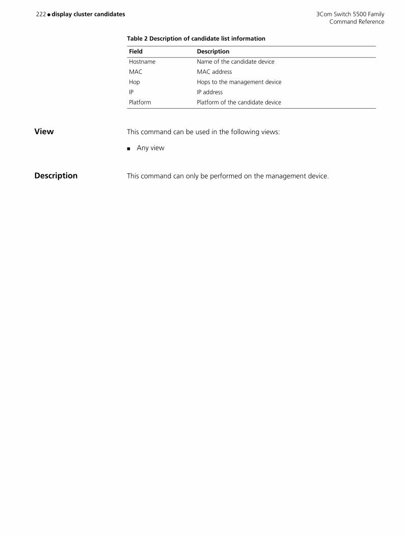
222 ● display cluster candidates 3Com Switch 5500 Family Command Reference
Table 2 Description of candidate list information
View This command can be used in the following views:
■ Any view
Description This command can only be performed on the management device.
Field Description
Hostname Name of the candidate device
MAC MAC address
Hop Hops to the management device
IP IP address
Platform Platform of the candidate device
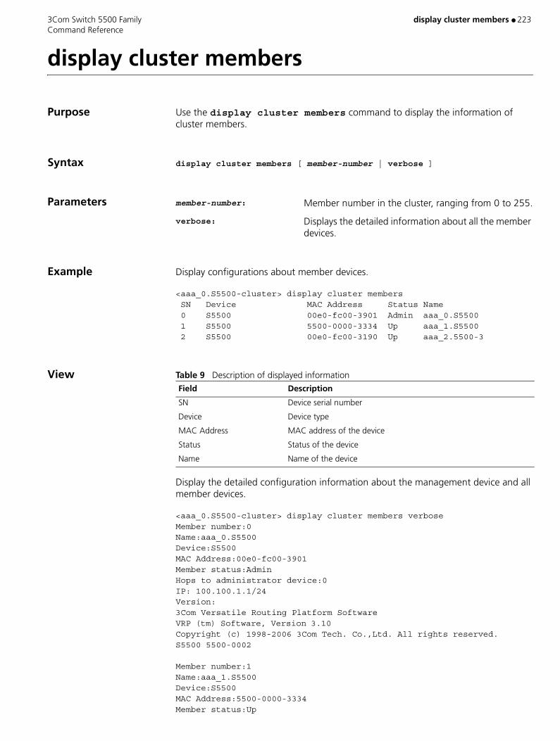
3Com Switch 5500 Family display cluster members ● 223 Command Reference
display cluster members
Purpose Use the display cluster members command to display the information of cluster members.
Syntax display cluster members [ member-number | verbose ]
Parameters member-number: Member number in the cluster, ranging from 0 to 255.
verbose: Displays the detailed information about all the member devices.
Example Display configurations about member devices.
<aaa_0.S5500-cluster> display cluster members SN Device MAC Address Status Name 0 S5500 00e0-fc00-3901 Admin aaa_0.S5500 1 S5500 5500-0000-3334 Up aaa_1.S5500 2 S5500 00e0-fc00-3190 Up aaa_2.5500-3
View Table 9 Description of displayed information
Display the detailed configuration information about the management device and all member devices.
<aaa_0.S5500-cluster> display cluster members verboseMember number:0Name:aaa_0.S5500Device:S5500MAC Address:00e0-fc00-3901Member status:AdminHops to administrator device:0IP: 100.100.1.1/24Version:3Com Versatile Routing Platform Software VRP (tm) Software, Version 3.10 Copyright (c) 1998-2006 3Com Tech. Co.,Ltd. All rights reserved. S5500 5500-0002
Member number:1Name:aaa_1.S5500Device:S5500MAC Address:5500-0000-3334Member status:Up
Field Description
SN Device serial number
Device Device type
MAC Address MAC address of the device
Status Status of the device
Name Name of the device

224 ● display cluster members 3Com Switch 5500 Family Command Reference
Hops to administrator device:2IP: 16.1.1.11/24Version:3Com Versatile Routing Platform Software VRP (tm) Software, Version 3.10 Copyright (c) 1998-2006 3Com Corporation. All rights reserved. S5500 5500-0002
Member number:2Name: aaa_2.S5500Device:S5500MAC Address:00e0-fc00-3190Member status:UpHops to administrator device:1IP: 16.1.1.1/24Version:3Com Versatile Routing Platform Software VRP (tm) Software, Version 3.10 Copyright (c) 1998-2006 3Com Corporation. All rights reserved. S5500 5500-0002
View This command can be used in the following views:
■ Any view
Description This command can only be performed on the management device.
Table 10 Description of displayed information
Field Description
Member number Device member number
Name Name of the device
Device Device type
MAC Address MAC address of the device
Member status Status of the device
Hops to administrator device
Hops from the current member device to the management device
IP IP address of the current member device
Version Software version of the current device

3Com Switch 5500 Family display config-agent ● 225 Command Reference
display config-agent
Purpose Use the display config-agent unit-id command to view statistics of the configuration agent.
Syntax display config-agent unit-id unit-id
Parameters unit-id Unit ID of current switch, in the range of 1 to 8.
Example To display statistics of the configuration agent on switch 1, enter the following:
<SW5500>display config-agent unit-id 1 Config-agent statistic information on Unit1Message type Successful Failed on Config message recv: 0 0 Config message send: 0 0 Notification message recv: 0 0 Notification message send: 0 0 Information message recv: 0 0 Information message send: 0 0
View This command can be used in the following views:
■ Any view
Description Configuration agent is one of the XRN features. You can log into one switch of the fabric to configure and manage the fabric by the configuration agent. The functions of the configuration agent include;
■ Distributing configuration commands to the right destination switches or processing modules based on the resolution result of the commands input.
■ Sending output information of the commands from the switch you have logged into to your terminal.
■ Supporting simultaneous configuration of multiple users.
You cannot configure the configuration agent, but can view the statistics of the configuration agent.
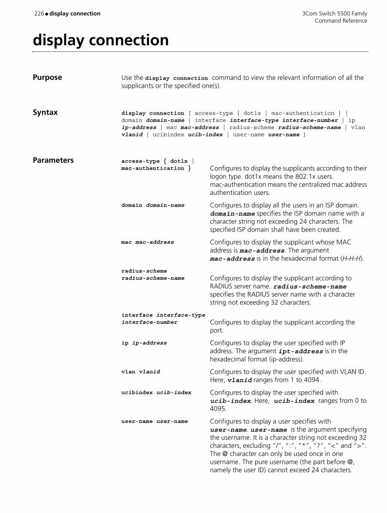
226 ● display connection 3Com Switch 5500 Family Command Reference
display connection
Purpose Use the display connection command to view the relevant information of all the supplicants or the specified one(s).
Syntax display connection [ access-type { dot1x | mac-authentication } | domain domain-name | interface interface-type interface-number | ip ip-address | mac mac-address | radius-scheme radius-scheme-name | vlan vlanid | ucibindex ucib-index | user-name user-name ]
Parameters access-type { dot1x | mac-authentication } Configures to display the supplicants according to their
logon type. dot1x means the 802.1x users. mac-authentication means the centralized mac address authentication users.
domain domain-name Configures to display all the users in an ISP domain. domain-name specifies the ISP domain name with a character string not exceeding 24 characters. The specified ISP domain shall have been created.
mac mac-address Configures to display the supplicant whose MAC address is mac-address. The argument mac-address is in the hexadecimal format (H-H-H).
radius-scheme radius-scheme-name Configures to display the supplicant according to
RADIUS server name. radius-scheme-name specifies the RADIUS server name with a character string not exceeding 32 characters.
interface interface-type interface-number Configures to display the supplicant according the
port.
ip ip-address Configures to display the user specified with IP address. The argument ipt-address is in the hexadecimal format (ip-address).
vlan vlanid Configures to display the user specified with VLAN ID. Here, vlanid ranges from 1 to 4094.
ucibindex ucib-index Configures to display the user specified with ucib-index. Here, ucib-index ranges from 0 to 4095.
user-name user-name Configures to display a user specifies with user-name. user-name is the argument specifying the username. It is a character string not exceeding 32 characters, excluding “/”, “:”, “*”, “?”, “<” and “>”. The @ character can only be used once in one username. The pure username (the part before @, namely the user ID) cannot exceed 24 characters.

3Com Switch 5500 Family display connection ● 227 Command Reference
Example To display the relevant information of all the users, enter the following:
<SW5500>display connectionTotal 0 connections matched ,0 listed.
View This command can be used in the following views:
■ Any view
Description The output can help you with the user connection diagnosis and troubleshooting.
If no parameter is specified, this command displays the related information about all connected users
Related Command cut connection
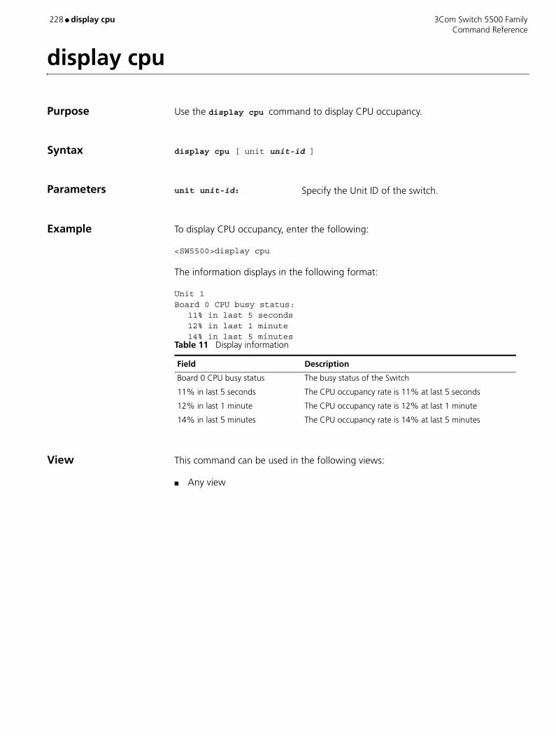
228 ● display cpu 3Com Switch 5500 Family Command Reference
display cpu
Purpose Use the display cpu command to display CPU occupancy.
Syntax display cpu [ unit unit-id ]
Parameters unit unit-id: Specify the Unit ID of the switch.
Example To display CPU occupancy, enter the following:
<SW5500>display cpu
The information displays in the following format:
Unit 1Board 0 CPU busy status:
11% in last 5 seconds12% in last 1 minute14% in last 5 minutes
View This command can be used in the following views:
■ Any view
Table 11 Display information
Field Description
Board 0 CPU busy status The busy status of the Switch
11% in last 5 seconds The CPU occupancy rate is 11% at last 5 seconds
12% in last 1 minute The CPU occupancy rate is 12% at last 1 minute
14% in last 5 minutes The CPU occupancy rate is 14% at last 5 minutes
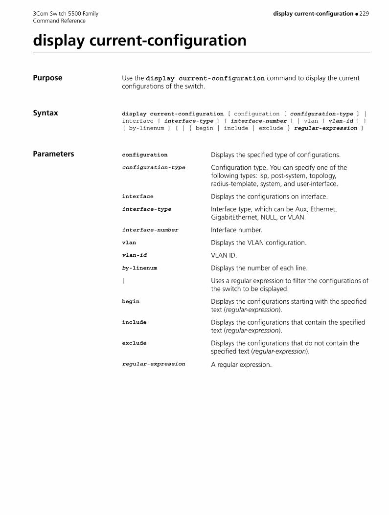
3Com Switch 5500 Family display current-configuration ● 229 Command Reference
display current-configuration
Purpose Use the display current-configuration command to display the current configurations of the switch.
Syntax display current-configuration [ configuration [ configuration-type ] | interface [ interface-type ] [ interface-number ] | vlan [ vlan-id ] ] [ by-linenum ] [ | { begin | include | exclude } regular-expression ]
Parameters configuration Displays the specified type of configurations.
configuration-type Configuration type. You can specify one of the following types: isp, post-system, topology, radius-template, system, and user-interface.
interface Displays the configurations on interface.
interface-type Interface type, which can be Aux, Ethernet, GigabitEthernet, NULL, or VLAN.
interface-number Interface number.
vlan Displays the VLAN configuration.
vlan-id VLAN ID.
by-linenum Displays the number of each line.
| Uses a regular expression to filter the configurations of the switch to be displayed.
begin Displays the configurations starting with the specified text (regular-expression).
include Displays the configurations that contain the specified text (regular-expression).
exclude Displays the configurations that do not contain the specified text (regular-expression).
regular-expression A regular expression.
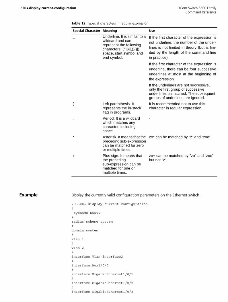
230 ● display current-configuration 3Com Switch 5500 Family Command Reference
Example Display the currently valid configuration parameters on the Ethernet switch.
<S5500> display current-configuration# sysname S5500 # radius scheme system # domain system # vlan 1 # vlan 2 # interface Vlan-interface2 # interface Aux1/0/0 # interface GigabitEthernet1/0/1 # interface GigabitEthernet1/0/2 # interface GigabitEthernet1/0/3
Table 12 Special characters in regular expression
Special Character Meaning Use
_ Underline. It is similar to a wildcard and can represent the following characters: (^|$|[,(){}]), space, start symbol and end symbol.
If the first character of the expression is not underline, the number of the under-lines is not limited in theory (but is lim-ited by the length of the command line in practice).
If the first character of the expression is underline, there can be four successive underlines at most at the beginning of the expression.
If the underlines are not successive, only the first group of successive underlines is matched. The subsequent groups of underlines are ignored.
( Left parenthesis. It represents the in-stack flag in programs.
It is recommended not to use this character in regular expression.
. Period. It is a wildcard which matches any character, including space.
-
* Asterisk. It means that the preceding sub-expression can be matched for zero or multiple times.
zo* can be matched by “z” and “zoo”.
+ Plus sign. It means that the preceding sub-expression can be matched for one or multiple times.
zo+ can be matched by "zo" and “zoo” but not "z".
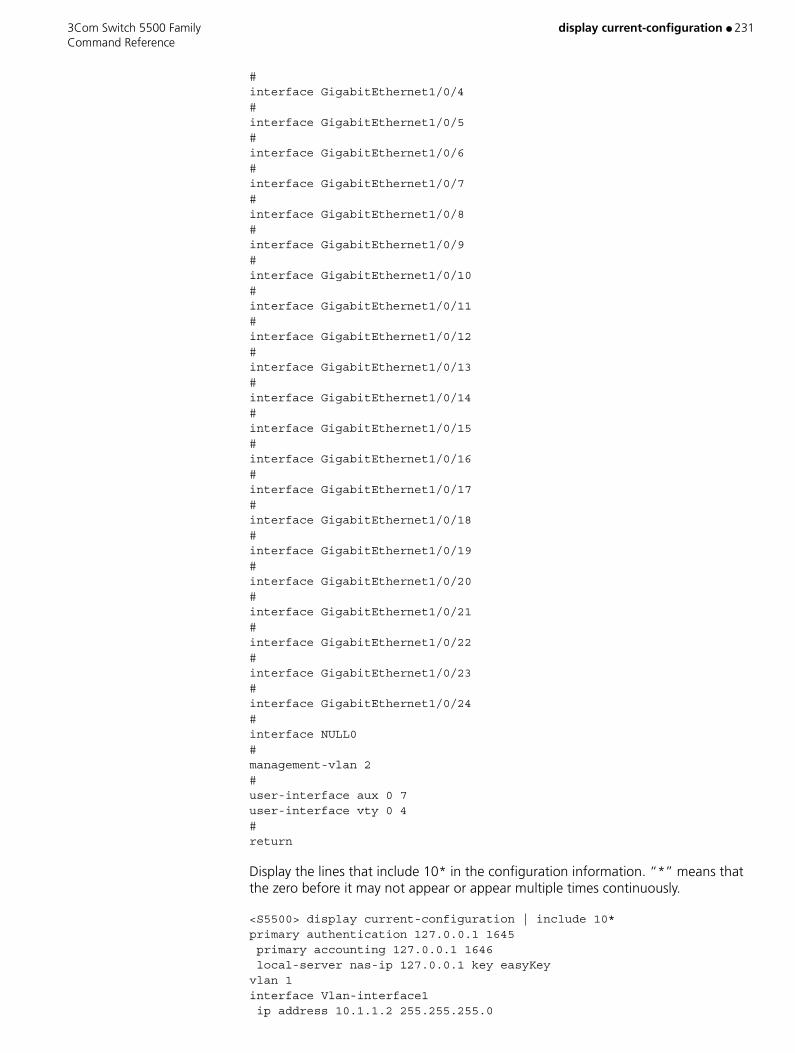
3Com Switch 5500 Family display current-configuration ● 231 Command Reference
# interface GigabitEthernet1/0/4 # interface GigabitEthernet1/0/5 # interface GigabitEthernet1/0/6 # interface GigabitEthernet1/0/7 # interface GigabitEthernet1/0/8 # interface GigabitEthernet1/0/9 # interface GigabitEthernet1/0/10 # interface GigabitEthernet1/0/11 # interface GigabitEthernet1/0/12 # interface GigabitEthernet1/0/13 # interface GigabitEthernet1/0/14 # interface GigabitEthernet1/0/15 # interface GigabitEthernet1/0/16 # interface GigabitEthernet1/0/17 # interface GigabitEthernet1/0/18 # interface GigabitEthernet1/0/19 # interface GigabitEthernet1/0/20 # interface GigabitEthernet1/0/21 # interface GigabitEthernet1/0/22 # interface GigabitEthernet1/0/23 # interface GigabitEthernet1/0/24 # interface NULL0 # management-vlan 2 # user-interface aux 0 7 user-interface vty 0 4 # return
Display the lines that include 10* in the configuration information. “*” means that the zero before it may not appear or appear multiple times continuously.
<S5500> display current-configuration | include 10*primary authentication 127.0.0.1 1645 primary accounting 127.0.0.1 1646 local-server nas-ip 127.0.0.1 key easyKeyvlan 1interface Vlan-interface1 ip address 10.1.1.2 255.255.255.0

232 ● display current-configuration 3Com Switch 5500 Family Command Reference
interface GigabitEthernet1/0/1 speed 1000interface GigabitEthernet1/0/2interface GigabitEthernet1/0/3interface GigabitEthernet1/0/4 network 10.1.1.0 0.0.0.255
Display the configuration information starting with “user”.
<S5500> display current-configuration | include ^useruser-interface aux 0user-interface vty 0 4
View This command can be used in the following views:
■ Any view
Description This command will not display those configuration parameters which have the same values with the corresponding default parameters.
After performing a group of configurations, you can use the display current-configuration command to verify the configuration results by checking the currently valid parameters in the display output. This command will not display the parameters whose corresponding functions do not take effect even though these parameters have been configured.
Related Commands ■ display saved-configuration
■ reset saved-configuration
■ save

3Com Switch 5500 Family display debugging ● 233 Command Reference
display debugging
Purpose Use the display debugging command to display the enabled debugging process.
Syntax display debugging |[ interface { interface_name | interface_type interface_num } ] [ module-name ]
Parameters interface-name Specifies the Ethernet port name.
interface-type Specifies the Ethernet port type.
interface-num Specifies the Ethernet port number.
module-name Specifies the module name.
Example Show all the enabled debugging.
<SW5500>display debuggingIP packet debugging switch is on.
View This command can be used in the following views:
■ Any view
Description Shows all the enabled debugging when there is no parameter.
Related Command debugging
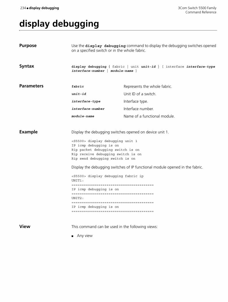
234 ● display debugging 3Com Switch 5500 Family Command Reference
display debugging
Purpose Use the display debugging command to display the debugging switches opened on a specified switch or in the whole fabric.
Syntax display debugging { fabric | unit unit-id } [ interface interface-type interface-number | module-name ]
Parameters fabric Represents the whole fabric.
unit-id Unit ID of a switch.
interface-type Interface type.
interface-number Interface number.
module-name Name of a functional module.
Example Display the debugging switches opened on device unit 1.
<S5500> display debugging unit 1IP icmp debugging is onRip packet debugging switch is onRip receive debugging switch is onRip send debugging switch is on
Display the debugging switches of IP functional module opened in the fabric.
<S5500> display debugging fabric ipUNIT1:========================================IP icmp debugging is on========================================UNIT2:========================================IP icmp debugging is on========================================
View This command can be used in the following views:
■ Any view

3Com Switch 5500 Family display debugging fabric by-module ● 235 Command Reference
display debugging fabric by-module
Purpose Use the display debugging fabric by-module command to display the debugging switches opened in the fabric by module names.
Syntax display debugging fabric by-module
Parameters None
Example Display the debugging switches opened in the fabric by module names.
<S5500> display debugging fabric by-moduleIP icmp debugging is on : unit1LACP packet debugging switch is on interface Ethernet1/0/23 : unit1Rip packet debugging switch is onRip receive debugging switch is onRip send debugging switch is on : unit1
View This command can be used in the following views:
■ Any view

236 ● display debugging ospf 3Com Switch 5500 Family Command Reference
display debugging ospf
Purpose Use the display debugging ospf command to view the debugging states of global OSPF and all processes.
Syntax display debugging ospf
Example To display the debugging states of global OSPF and all processes, enter the following.
<SW5500>display debugging ospfOSPF global debugging state:OSPF SPF debugging is onOSPF LSA debugging is onOSPF process 100 debugging state:OSPF SPF debugging is on
OSPF process 200 debugging state:OSPF SPF debugging is onOSPF LSA debugging is on
View This command can be used in the following views:
■ Any view
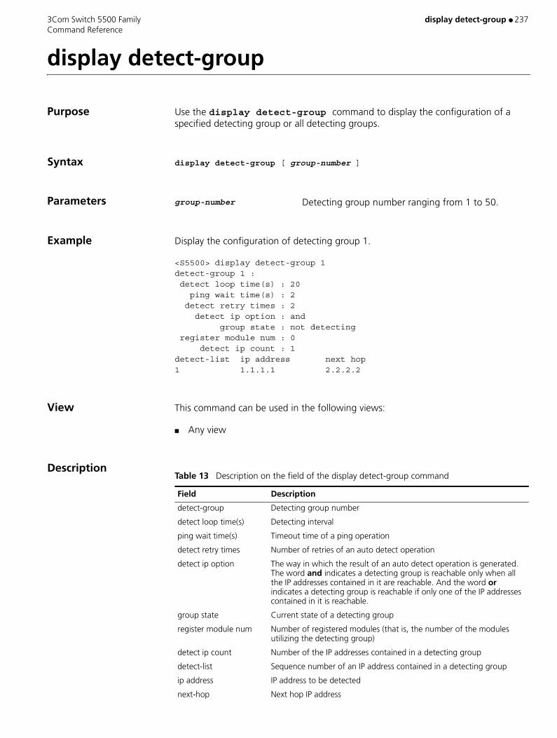
3Com Switch 5500 Family display detect-group ● 237 Command Reference
display detect-group
Purpose Use the display detect-group command to display the configuration of a specified detecting group or all detecting groups.
Syntax display detect-group [ group-number ]
Parameters group-number Detecting group number ranging from 1 to 50.
Example Display the configuration of detecting group 1.
<S5500> display detect-group 1detect-group 1 : detect loop time(s) : 20 ping wait time(s) : 2 detect retry times : 2 detect ip option : and group state : not detecting register module num : 0 detect ip count : 1detect-list ip address next hop1 1.1.1.1 2.2.2.2
View This command can be used in the following views:
■ Any view
DescriptionTable 13 Description on the field of the display detect-group command
Field Description
detect-group Detecting group number
detect loop time(s) Detecting interval
ping wait time(s) Timeout time of a ping operation
detect retry times Number of retries of an auto detect operation
detect ip option The way in which the result of an auto detect operation is generated. The word and indicates a detecting group is reachable only when all the IP addresses contained in it are reachable. And the word or indicates a detecting group is reachable if only one of the IP addresses contained in it is reachable.
group state Current state of a detecting group
register module num Number of registered modules (that is, the number of the modules utilizing the detecting group)
detect ip count Number of the IP addresses contained in a detecting group
detect-list Sequence number of an IP address contained in a detecting group
ip address IP address to be detected
next-hop Next hop IP address
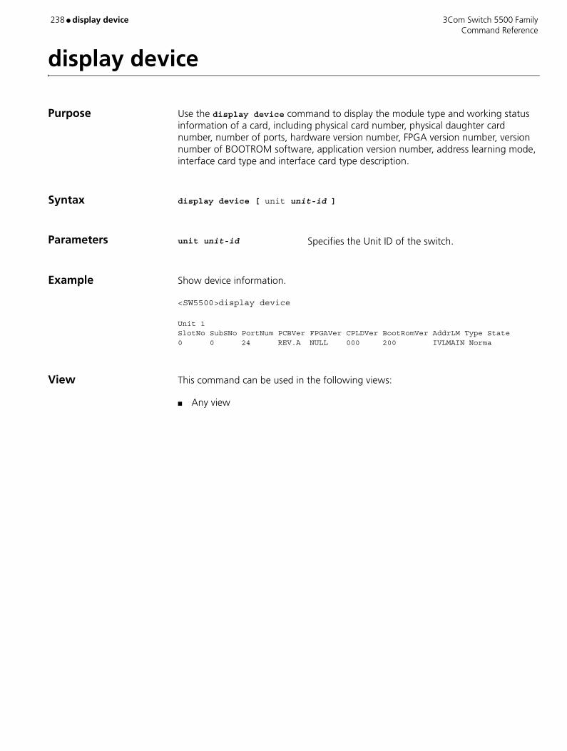
238 ● display device 3Com Switch 5500 Family Command Reference
display device
Purpose Use the display device command to display the module type and working status information of a card, including physical card number, physical daughter card number, number of ports, hardware version number, FPGA version number, version number of BOOTROM software, application version number, address learning mode, interface card type and interface card type description.
Syntax display device [ unit unit-id ]
Parameters unit unit-id Specifies the Unit ID of the switch.
Example Show device information.
<SW5500>display device
Unit 1SlotNo SubSNo PortNum PCBVer FPGAVer CPLDVer BootRomVer AddrLM Type State0 0 24 REV.A NULL 000 200 IVLMAIN Norma
View This command can be used in the following views:
■ Any view
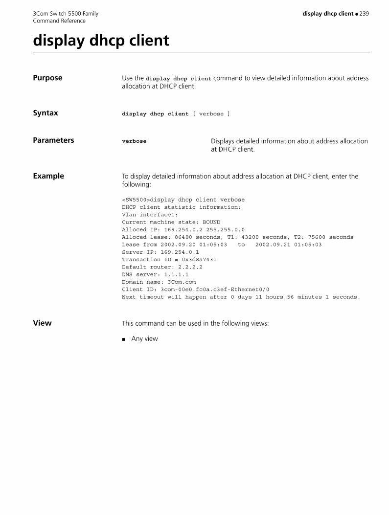
3Com Switch 5500 Family display dhcp client ● 239 Command Reference
display dhcp client
Purpose Use the display dhcp client command to view detailed information about address allocation at DHCP client.
Syntax display dhcp client [ verbose ]
Parameters verbose Displays detailed information about address allocation at DHCP client.
Example To display detailed information about address allocation at DHCP client, enter the following:
<SW5500>display dhcp client verboseDHCP client statistic information:Vlan-interface1:Current machine state: BOUNDAlloced IP: 169.254.0.2 255.255.0.0Alloced lease: 86400 seconds, T1: 43200 seconds, T2: 75600 secondsLease from 2002.09.20 01:05:03 to 2002.09.21 01:05:03Server IP: 169.254.0.1Transaction ID = 0x3d8a7431Default router: 2.2.2.2DNS server: 1.1.1.1Domain name: 3Com.comClient ID: 3com-00e0.fc0a.c3ef-Ethernet0/0Next timeout will happen after 0 days 11 hours 56 minutes 1 seconds.
View This command can be used in the following views:
■ Any view

240 ● display dhcp-security 3Com Switch 5500 Family Command Reference
display dhcp-security
Purpose Use the display dhcp-security command to display one or all user address entries, or a specified type of user address entries in the valid user address table of a DHCP server group.
Syntax display dhcp-security [ ip-address | dynamic | static | tracker ]
Parameters ip-address IP address. This argument is used to display the user address entry with the specified IP address.
dynamic Displays the dynamic user address entries.
static Displays the static user address entries.
tracker Displays the interval to update the user address entries of a DHCP-security table.
Example Display all user address entries contained in the valid user address table of the DHCP server group.
<S5500> display dhcp-securityIP Address MAC AddressIP Address Type2.2.2.3 0005-5d02-f2b2Static3.3.3.3 0005-5d02-f2b3Dynamic--- 2 dhcp-security item(s) found ---
View This command can be used in the following views:
■ Any view
Description Among Switch 5500-series switches, only Switch 5500 El-series switches support this command.
Table 14 Description on the fields of the display dhcp-security command
Field Description
IP Address IP address of a user of the DHCP server group
MAC Address MAC address of the user of the DHCP server group
IP Address Type Type of the user address entry (static/dynamic)

3Com Switch 5500 Family display dhcp-server ● 241 Command Reference
display dhcp-server
Purpose Use the display dhcp-server command to display information about a specified DHCP server group.
Syntax display dhcp-server groupNo
Parameters groupNo DHCP server group number. Valid values are 0 to 19.
Example Display information about DHCP server group 0.
<S5500> display dhcp-server 0IP address of DHCP server group 0: 1.1.1.1IP address of DHCP server group 0: 2.2.2.2IP address of DHCP server group 0: 3.3.3.3IP address of DHCP server group 0: 4.4.4.4IP address of DHCP server group 0: 5.5.5.5IP address of DHCP server group 0: 6.6.6.6IP address of DHCP server group 0: 7.7.7.7IP address of DHCP server group 0: 8.8.8.8Messages from this server group: 0Messages to this server group: 0Messages from clients to this server group: 0Messages from this server group to clients: 0DHCP_OFFER messages: 0DHCP_ACK messages: 0DHCP_NAK messages: 0DHCP_DECLINE messages: 0DHCP_DISCOVER messages: 0DHCP_REQUEST messages: 0DHCP_INFORM messages: 0DHCP_RELEASE messages: 0BOOTP_REQUEST messages: 0BOOTP_REPLY messages: 0
Table 15 Description on the fields of the display dhcp-server command
Field Description
IP address of DHCP server group 0: DHCP server IP addresses of DHCP server group 0
Messages from this server group Number of the packets received from the DHCP server group
Messages to this server group Number of the packets sent to the DHCP server group
Messages from clients to this server group Number of the packets received from the DHCP clients
Messages from this server group to clients Number of the packets sent to the DHCP clients
DHCP_OFFER messages Number of the received DHCP-OFFER packets
DHCP_ACK messages Number of the received DHCP-ACK packets
DHCP_NAK messages Number of the received DHCP-NAK packets
DHCP_DECLINE messages Number of the received DHCP-DECLINE packets
DHCP_DISCOVER messages Number of the received DHCP-DISCOVER packets
DHCP_REQUEST messages Number of the received DHCP-REQUEST packets
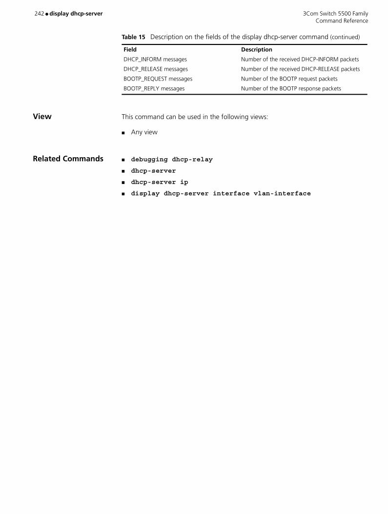
242 ● display dhcp-server 3Com Switch 5500 Family Command Reference
View This command can be used in the following views:
■ Any view
Related Commands ■ debugging dhcp-relay
■ dhcp-server
■ dhcp-server ip
■ display dhcp-server interface vlan-interface
DHCP_INFORM messages Number of the received DHCP-INFORM packets
DHCP_RELEASE messages Number of the received DHCP-RELEASE packets
BOOTP_REQUEST messages Number of the BOOTP request packets
BOOTP_REPLY messages Number of the BOOTP response packets
Table 15 Description on the fields of the display dhcp-server command (continued)
Field Description

3Com Switch 5500 Family display dhcp server conflict ● 243 Command Reference
display dhcp server conflict
Purpose Use the display dhcp server conflict command to display the statistics of IP address conflicts on the DHCP server.
Syntax display dhcp server conflict { all | ip ip-address }
Parameters all Specifies all IP addresses.
ip-address Specifies one IP address.
Example Display the statistics of IP address conflicts.
<S5500> display dhcp server conflict allAddress Discover Time10.110.1.2 Jan 11 2003 11:57: 7 PM
View This command can be used in the following views:
■ Any view
Description This command applies only to the S5500-EI series among Switch 5500-Series Switches.
Related Command reset dhcp server conflict
Table 16 Description on the fields of the display dhcp server conflict command
Field Description
Address Conflicting IP address
Discover Time Time when the conflict is detected

244 ● display dhcp server expired 3Com Switch 5500 Family Command Reference
display dhcp server expired
Purpose Use the display dhcp server expired command to display the lease expiration information about one IP address, or the lease expiration information about all IP addresses in one or all DHCP address pools.
Syntax display dhcp server expired { ip ip-address | pool [ pool-name ] | interface [ interface-type interface-number ] all }
Parameters ip ip-address Specifies an IP address.
pool [ pool-name ] Specifies a global address pool. The pool-name argument, a string of 1 to 35 characters, is the name of an address pool. If you do not provide this argument, this command applies to all global address pools.
interface [ interface-type interface-number ] Specifies a VLAN interface. If you do not specify a
VLAN interface, this command applies to all VLAN interfaces.
all Specifies all DHCP address pools.
Example Display the lease expiration information about the IP addresses in all DHCP address pools.
<S5500> display dhcp server expired allGlobal pool:IP address Client-identifier/ Lease expiration Type Hardware address
Interface pool: IP address Client-identifier/ Lease expiration Type Hardware address--- total 0 entry ---
Table 17 Description on the fields of the display dhcp server expired command
Field Description
Global pool The information about the expired IP addresses of global address pools
Interface pool The information about the expired IP addresses of interface address pools
IP address Bound IP addresses
Client-identifier/Hardware address User ID or MAC addresses to which IP addresses are bound
Lease expiration The time when a lease time expires
Type Address binding type

3Com Switch 5500 Family display dhcp server expired ● 245 Command Reference
View This command can be used in the following views:
■ Any view
Description When all the IP addresses in an address pool are assigned, the DHCP server assigns the IP addresses that are expired to DHCP clients.
This command applies only to the S5500-EI series among Switch 5500-Series Switches.

246 ● display dhcp server free-ip 3Com Switch 5500 Family Command Reference
display dhcp server free-ip
Purpose Use the display dhcp server free-ip command to display the free (that is, unassigned) IP addresses.
Syntax display dhcp server free-ip
Parameters None
Example Display the free IP addresses.
<S5500> display dhcp server free-ipIP Range from 1.0.0.0 to 2.2.2.1IP Range from 2.2.2.3 to 2.255.255.255IP Range from 4.0.0.0 to 4.255.255.255IP Range from 5.5.5.0 to 5.5.5.0IP Range from 5.5.5.2 to 5.5.5.255
View This command can be used in the following views:
■ Any view
Description This command applies only to the S5500-EI series among Switch 5500-Series Switches.

3Com Switch 5500 Family display dhcp-server interface vlan-interface ● 247 Command Reference
display dhcp-server interface vlan-interface
Purpose Use the display dhcp-server interface vlan-interface command to display information about the DHCP server group to which a VLAN interface is mapped.
Syntax display dhcp-server interface vlan-interface vlan-id
Parameters vlan-id VLAN ID.
Examples Display information about the DHCP server group to which VLAN 2 interface is mapped.
<S5500> display dhcp-server interface vlan-interface 2The DHCP server group of this interface is 0The above display information indicates the VLAN 2 interface is mapped to DHCP server group 0.
View This command can be used in the following views:
■ Any view
Related Commands ■ debugging dhcp-relay
■ dhcp-server
■ display dhcp-server

248 ● display dhcp server ip-in-use 3Com Switch 5500 Family Command Reference
display dhcp server ip-in-use
Purpose Use the display dhcp server ip-in-use command to display the address binding information of one IP address, the specified DHCP address pool(s) or all DHCP address pools.
Syntax display dhcp server ip-in-use { ip ip-address | pool [ pool-name ] | interface [ interface-type interface-number ] all }
Parameters ip ip-address Specifies an IP address.
pool [ pool-name ] Specifies a global address pool. The pool-name argument, a string of 1 to 35 characters, is the name of an address pool. If you do not provide this argument, this command applies to all global address pools.
interface [ interface-type interface-number ] Specifies a VLAN interface. If you do not specify a
VLAN interface, this command applies to all VLAN interfaces.
all Specifies all address pools.
Example Display the address binding information of all DHCP address pools.
<S5500> display dhcp server ip-in-use allGlobal pool:IP address Client-identifier/ Lease expiration Type Hardware address2.2.2.2 44444-4444-4444 NOT Used Manual
Interface pool: IP address Client-identifier/ Lease expiration Type Hardware address5.5.5.1 0050-ba28-930a Jun 5 2003 10:56: 7 AM Auto:COMMITE
--- total 0 entry ---
View This command can be used in the following views:
■ Any view
Table 18 Description on the fields of the display dhcp server ip-in-use command
Field Description
Global pool Address binding information of global DHCP address pools
Interface pool Address binding information of interface DHCP address pools
IP address Bound IP address
Client-identifier/Hardware address User ID or MAC address to which the IP address is bound
Lease expiration Time when the lease expires
Type Address binding type

3Com Switch 5500 Family display dhcp server ip-in-use ● 249 Command Reference
Description This command applies only to the S5500-EI series among Switch 5500-Series Switches.
Related Command reset dhcp server ip-in-use

250 ● display dhcp server statistics 3Com Switch 5500 Family Command Reference
display dhcp server statistics
Purpose Use the display dhcp server statistics command to display the statistics on a DHCP server.
Syntax display dhcp server statistics
Parameters None
Example Display the statistics on a DHCP server.
<S5500> display dhcp server statistics Global Pool: Pool Number:5 Binding Auto:0 Manual:1 Expire:0 Interface Pool: Pool Number:1 Binding Auto:1 Manual:0 Expire:0 Boot Request:6 Dhcp Discover:1 Dhcp Request:4 Dhcp Decline:0 Dhcp Release:1 Dhcp Inform:0 Boot Reply:4 Dhcp Offer:1 Dhcp Ack:3 Dhcp Nak:0 Bad Messages:0
Table 19 Description on the fields of the display dhcp server statistics command
Field Description
Global Pool Statistics about global address pools
Interface Pool Statistics about interface address pools
Pool Number Number of address pools
Auto Number of the automatically bound IP addresses
Manual Number of the manually bound IP addresses

3Com Switch 5500 Family display dhcp server statistics ● 251 Command Reference
View This command can be used in the following views:
■ Any view
Description This command applies only to the S5500-EI series among Switch 5500-Series Switches.
Related Command reset dhcp server statistics
Expire Number of the expired IP addresses
Boot Request: 6
Dhcp Discover: 1
Dhcp Request: 4
Dhcp Decline: 0
Dhcp Release: 1
Dhcp Inform: 0 Statistics about the DHCP packets received from DHCP clients
Boot Reply: 4
Dhcp Offer: 1
Dhcp Ack: 3
Dhcp Nak: 0 Statistics about the DHCP packets sent to DHCP clients
Bad Messages Number of the error DHCP packets
Table 19 Description on the fields of the display dhcp server statistics command (continued)
Field Description

252 ● display dhcp server tree 3Com Switch 5500 Family Command Reference
display dhcp server tree
Purpose Use the display dhcp server tree command to display information about address pool tree.
Syntax display dhcp server tree { pool [ pool-name ] | interface [ interface-type interface-number ] | all }
Parameters pool [ pool-name ] Specifies a global address pool. The pool-name argument, a string of 1 to 35 characters, is the name of an address pool. If you do not provide this argument, this command applies to all global address pools.
interface [ interface-type interface-number ] Specifies a VLAN interface. If you do not specify a
VLAN interface, this command applies to all VLAN interfaces.
all Specifies all address pools.
Example Display information about address pool tree.
<S5500> display dhcp server tree allGlobal pool:Pool name: 5network 10.10.1.0 mask 255.255.255.0Child node:6Sibling node:7 option 1 ip-address 255.0.0.0 expired 1 0 0 option 58 hex 00 00 A8 C0 option 59 hex 00 00 00 3C
Pool name: 6 static-bind ip-address 10.10.1.2 mask 255.0.0.0 static-bind mac-address 00e0-00fc-0001Parent node:5 option 1 ip-address 255.255.0. expired 1 0 0 option 58 hex 00 00 A8 C0 option 59 hex 00 00 00 3C
Pool name: 7network 10.10.1.64 mask 255.255.255.192PrevSibling node:5 option 1 ip-address 255.0.0.0 gateway-list 2.2.2.2 dns-list 1.1.1.1 domain-name 444444 nbns-list 3.3.3.3 expired 1 0 0 option 58 hex 00 00 A8 C0 option 59 hex 00 00 00 3C

3Com Switch 5500 Family display dhcp server tree ● 253 Command Reference
View This command can be used in the following views:
■ Any view
Description This command applies only to the S5500-EI series among Switch 5500-Series Switches.
Table 20 Description on the fields of the display dhcp server tree command
Field Description
Global pool Information about global address pools
Interface pool Information about interface address pools
Pool name Address pool name
network Assignable IP address range
static-bind ip-address 10.10.1.2 mask 255.0.0.0
static-bind mac-address 00e0-00fc-0001 Statically bound IP and MAC addresses
Child node:6 The address pool 6 is the child node of this node.
This field can display the information about the following types of node:
Child node: Displays the information about an address pool that is a child of the current address pool.
Parent node: Displays the information about the address pool that is the parent of the current address pool.
Sibling node: Displays the information about the next sibling address pool of the current address pool. (The order of sibling address pools are determined by the time when they are configured.)
PrevSibling node: Displays the information about the previous sibling address pool of the current address pool.
option Customized DHCP options
expired The address lease time (in terms of number of days, hours, and minutes)
gateway-list List of the gateways configured for the DHCP clients
dns-list List of the DNS servers configured for the DHCP clients
domain-name The domain name configured for the DHCP clients
nbns-list List of the NetBIOS servers configured for the DHCP clients

254 ● display dhcp-snooping 3Com Switch 5500 Family Command Reference
display dhcp-snooping
Purpose Use the display dhcp-snooping command to display the user IP-MAC address mapping entries recorded by the DHCP snooping function.
Syntax display dhcp-snooping [ unit unit-id ]
Parameters unit-id ID of a unit in a fabric.
Example Display the user IP-MAC address mapping entries recorded by the DHCP snooping function.
<S5500> display dhcp-snoopingDHCP-Snooping is enabled. Type : D--Dynamic , S--Static Unit ID : 1 Type IP Address MAC Address Lease VLAN Interface ==== =============== =============== ========= ==== =================--- 0 dhcp-snooping item(s) of unit 1 found ---
View This command can be used in the following views:
■ Any view
Related Command dhcp-snooping
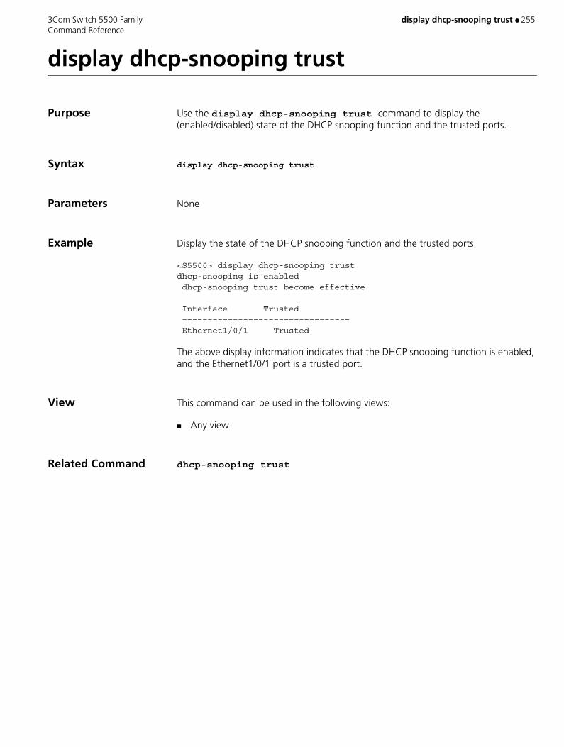
3Com Switch 5500 Family display dhcp-snooping trust ● 255 Command Reference
display dhcp-snooping trust
Purpose Use the display dhcp-snooping trust command to display the (enabled/disabled) state of the DHCP snooping function and the trusted ports.
Syntax display dhcp-snooping trust
Parameters None
Example Display the state of the DHCP snooping function and the trusted ports.
<S5500> display dhcp-snooping trustdhcp-snooping is enabled dhcp-snooping trust become effective
Interface Trusted ================================= Ethernet1/0/1 Trusted
The above display information indicates that the DHCP snooping function is enabled, and the Ethernet1/0/1 port is a trusted port.
View This command can be used in the following views:
■ Any view
Related Command dhcp-snooping trust

256 ● display diagnostic-information 3Com Switch 5500 Family Command Reference
display diagnostic-information
Purpose Use the display diagnostic-information command to display the system diagnostic information, or save the system diagnostic information to a file (with a suffix of "diag") in the flash memory.
Syntax display diagnostic-information
Parameters None
Example Save the system diagnostic information to the default.diag file.
<S5500> display diagnostic-information This operation may take a few minutes, continue?[Y/N]y Diagnostic-information is saved to Flash or displayed(Y=save N=display)?[Y/N]y Please input the file name(*.diag)[flash:/default.diag]: The file is already existing, overwrite it? [Y/N]y
% Output information to file: flash:/default.diag.Please wait......
View This command can be used in the following views:
■ User view
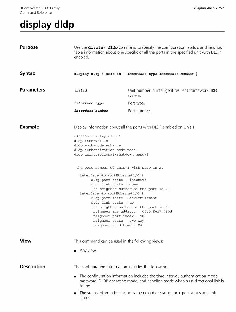
3Com Switch 5500 Family display dldp ● 257 Command Reference
display dldp
Purpose Use the display dldp command to specify the configuration, status, and neighbor table information about one specific or all the ports in the specified unit with DLDP enabled.
Syntax display dldp { unit-id | interface-type interface-number }
Parameters unitid Unit number in intelligent resilient framework (IRF) system.
interface-type Port type.
interface-number Port number.
Example Display information about all the ports with DLDP enabled on Unit 1.
<S5500> display dldp 1dldp interval 10dldp work-mode enhancedldp authentication-mode nonedldp unidirectional-shutdown manual
The port number of unit 1 with DLDP is 2.
interface GigabitEthernet2/0/1 dldp port state : inactive dldp link state : down The neighbor number of the port is 0.
interface GigabitEthernet2/0/2 dldp port state : advertisement
dldp link state : up The neighbor number of the port is 1. neighbor mac address : 00e0-fc27-750d neighbor port index : 98 neighbor state : two way neighbor aged time : 24
View This command can be used in the following views:
■ Any view
Description The configuration information includes the following:
■ The configuration information includes the time interval, authentication mode, password, DLDP operating mode, and handling mode when a unidirectional link is found.
■ The status information includes the neighbor status, local port status and link status.

258 ● display dldp 3Com Switch 5500 Family Command Reference
■ The neighbor table includes the MAC address, port ID, neighbor status and aging time items.
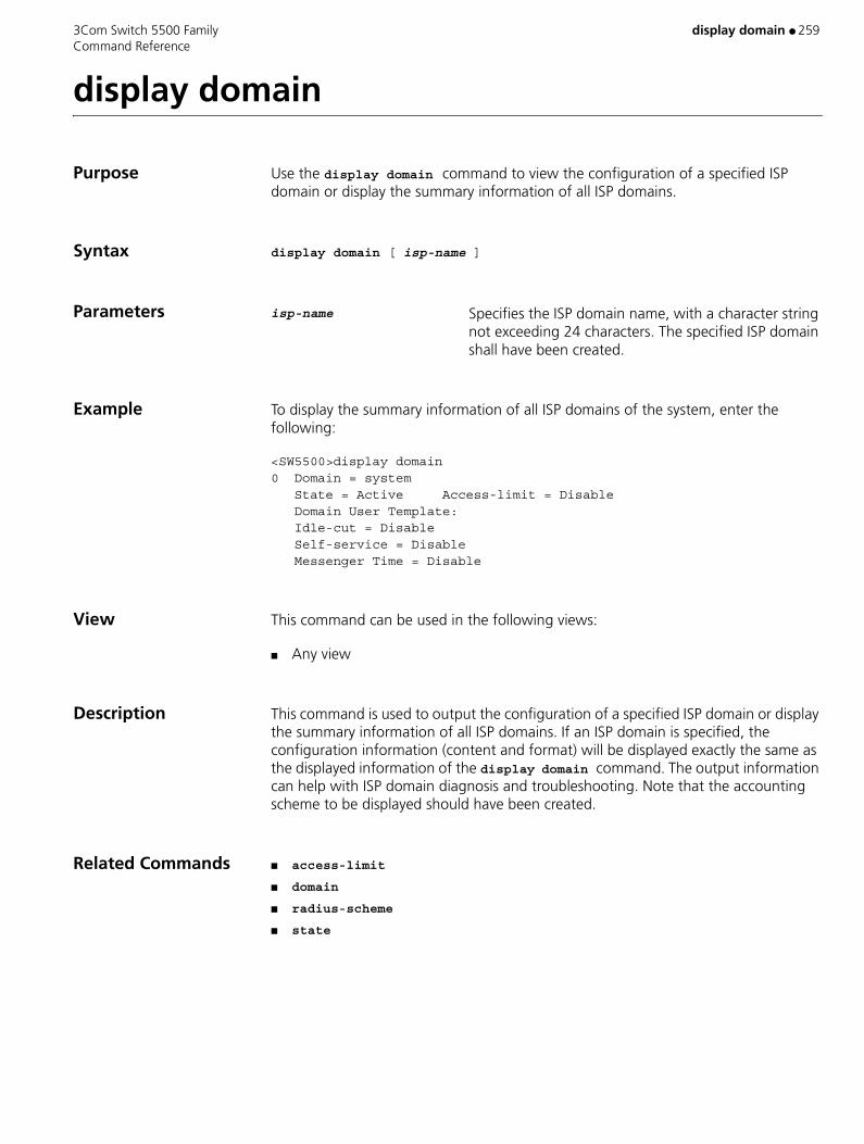
3Com Switch 5500 Family display domain ● 259 Command Reference
display domain
Purpose Use the display domain command to view the configuration of a specified ISP domain or display the summary information of all ISP domains.
Syntax display domain [ isp-name ]
Parameters isp-name Specifies the ISP domain name, with a character string not exceeding 24 characters. The specified ISP domain shall have been created.
Example To display the summary information of all ISP domains of the system, enter the following:
<SW5500>display domain0 Domain = system State = Active Access-limit = Disable Domain User Template: Idle-cut = Disable Self-service = Disable Messenger Time = Disable
View This command can be used in the following views:
■ Any view
Description This command is used to output the configuration of a specified ISP domain or display the summary information of all ISP domains. If an ISP domain is specified, the configuration information (content and format) will be displayed exactly the same as the displayed information of the display domain command. The output information can help with ISP domain diagnosis and troubleshooting. Note that the accounting scheme to be displayed should have been created.
Related Commands ■ access-limit
■ domain
■ radius-scheme
■ state
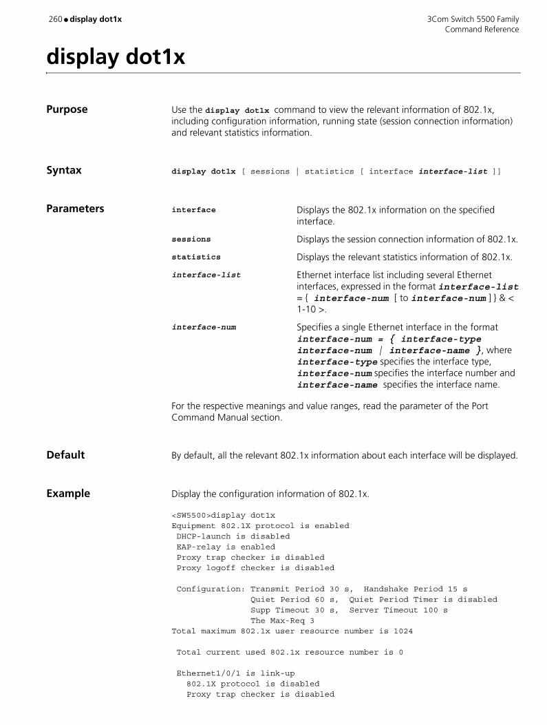
260 ● display dot1x 3Com Switch 5500 Family Command Reference
display dot1x
Purpose Use the display dot1x command to view the relevant information of 802.1x, including configuration information, running state (session connection information) and relevant statistics information.
Syntax display dot1x [ sessions | statistics [ interface interface-list ]]
Parameters interface Displays the 802.1x information on the specified interface.
sessions Displays the session connection information of 802.1x.
statistics Displays the relevant statistics information of 802.1x.
interface-list Ethernet interface list including several Ethernet interfaces, expressed in the format interface-list = { interface-num [ to interface-num ] } & < 1-10 >.
interface-num Specifies a single Ethernet interface in the format interface-num = { interface-type interface-num | interface-name }, where interface-type specifies the interface type, interface-num specifies the interface number and interface-name specifies the interface name.
For the respective meanings and value ranges, read the parameter of the Port Command Manual section.
Default By default, all the relevant 802.1x information about each interface will be displayed.
Example Display the configuration information of 802.1x.
<SW5500>display dot1x Equipment 802.1X protocol is enabled DHCP-launch is disabled EAP-relay is enabled Proxy trap checker is disabled Proxy logoff checker is disabled
Configuration: Transmit Period 30 s, Handshake Period 15 sQuiet Period 60 s, Quiet Period Timer is disabledSupp Timeout 30 s, Server Timeout 100 sThe Max-Req 3
Total maximum 802.1x user resource number is 1024
Total current used 802.1x resource number is 0
Ethernet1/0/1 is link-up 802.1X protocol is disabled Proxy trap checker is disabled

3Com Switch 5500 Family display dot1x ● 261 Command Reference
Proxy logoff checker is disabled The port is a(n) authenticator Authenticate Mode is auto Port Control Type is Mac-based Max on-line user number is 256… (Omitted)
View This command can be used in the following views:
■ Any view
By default, all the relevant 802.1x information about each interface will be displayed.
This command can be used to display the following information on the specified interface: 802.1x configuration, state or statistics. If no port is specified when executing this command, the system will display all 802.1x related information. For example, 802.1x configuration of all ports, 802.1x session connection information, and 802.1x data statistical information. The output information of this command can help the user to verify the current 802.1x configurations so as to troubleshoot 802.1x.
■ dot1x
■ dot1x max-user
■ dot1x port-control
■ dot1x port-method
■ dot1x retry
■ reset dot1x statistics
■ timer
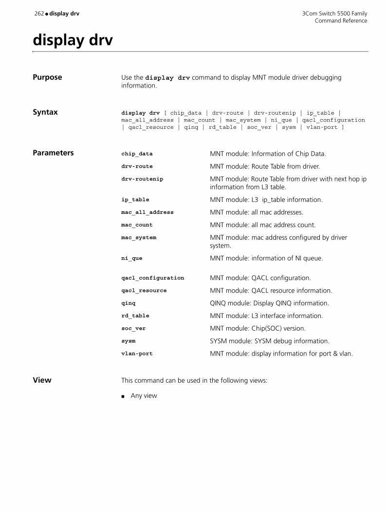
262 ● display drv 3Com Switch 5500 Family Command Reference
display drv
Purpose Use the display drv command to display MNT module driver debugging information.
Syntax display drv [ chip_data | drv-route | drv-routenip | ip_table | mac_all_address | mac_count | mac_system | ni_que | qacl_configuration | qacl_resource | qinq | rd_table | soc_ver | sysm | vlan-port ]
Parameters chip_data MNT module: Information of Chip Data.
drv-route MNT module: Route Table from driver.
drv-routenip MNT module: Route Table from driver with next hop ip information from L3 table.
ip_table MNT module: L3 ip_table information.
mac_all_address MNT module: all mac addresses.
mac_count MNT module: all mac address count.
mac_system MNT module: mac address configured by driver system.
ni_que MNT module: information of NI queue.
qacl_configuration MNT module: QACL configuration.
qacl_resource MNT module: QACL resource information.
qinq QINQ module: Display QINQ information.
rd_table MNT module: L3 interface information.
soc_ver MNT module: Chip(SOC) version.
sysm SYSM module: SYSM debug information.
vlan-port MNT module: display information for port & vlan.
View This command can be used in the following views:
■ Any view
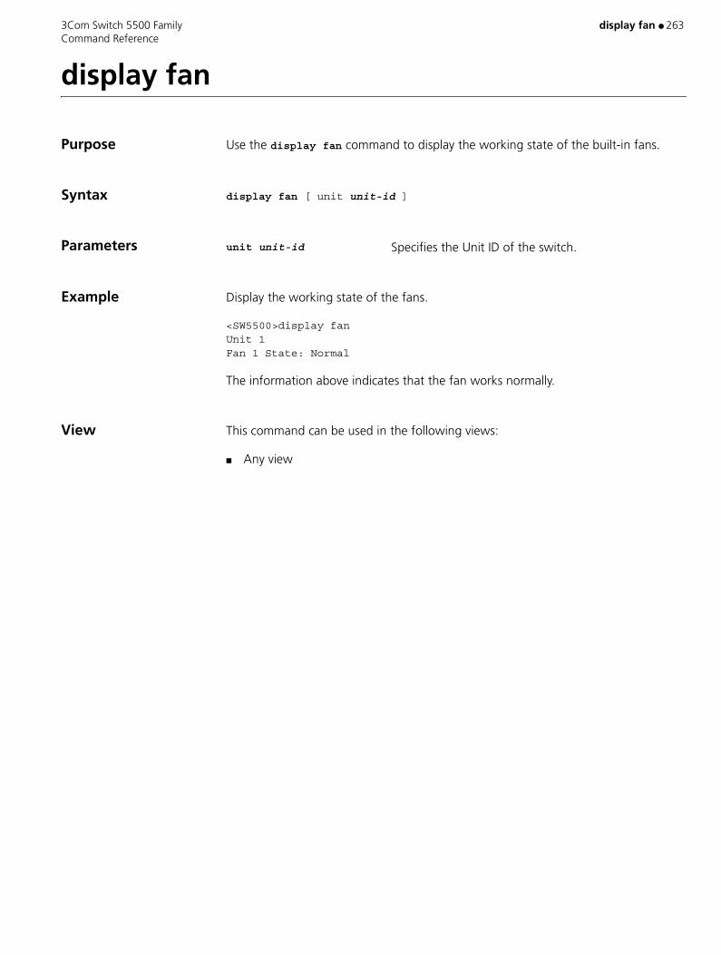
3Com Switch 5500 Family display fan ● 263 Command Reference
display fan
Purpose Use the display fan command to display the working state of the built-in fans.
Syntax display fan [ unit unit-id ]
Parameters unit unit-id Specifies the Unit ID of the switch.
Example Display the working state of the fans.
<SW5500>display fanUnit 1Fan 1 State: Normal
The information above indicates that the fan works normally.
View This command can be used in the following views:
■ Any view
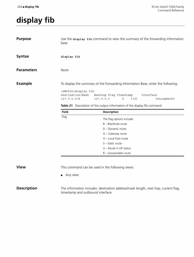
264 ● display fib 3Com Switch 5500 Family Command Reference
display fib
Purpose Use the display fib command to view the summary of the forwarding information base.
Syntax display fib
Parameters None
Example To display the summary of the Forwarding Information Base, enter the following:
<SW5500>display fibDestination/Mask Nexthop Flag TimeStamp Interface127.0.0.0/8 127.0.0.1 U t[0] InLoopBack0
View This command can be used in the following views:
■ Any view
Description The information includes: destination address/mask length, next hop, current flag, timestamp and outbound interface.
Table 21 Description of the output information of the display fib command
Field Description
FlagThe flag options include:
B – Blackhole route
D – Dynamic route
G – Gateway route
H – Local host route
S – Static route
U – Route in UP status
R – Unreachable route

3Com Switch 5500 Family display fib ● 265 Command Reference
display fib
Purpose Use the display fib command to view the FIB entries which are output from the buffer according to regular expression and related to the specific character string.
Syntax display fib | { { begin | include | exclude } text }
Parameters begin Displays the FIB entries from the first one containing the character string text.
include Displays only those FIB entries containing the character string text.
exclude Displays only those FIB entries excluding the character string text.
text Displays string of specific characters.
Example To display the lines starting from the first one containing the string 169.254.0.0, enter the following:
<SW5500>display fib | begin 169.254.0.0Destination/MaskNexthopFlagTimeStampInterface169.254.0.0/16 2.1.1.1Ut[0]Vlan-interface12.0.0.0/16 2.1.1.1Ut[0]Vlan-interface1
View This command can be used in the following views:
■ Any view

266 ● display fib acl 3Com Switch 5500 Family Command Reference
display fib acl
Purpose Use the display fib acl command to view the FIB entries matching a specific ACL.
Syntax display fib acl number
Parameters number Enter the ACL in number form. Valid values are 2000 to 2999
Example To display the FIB entries matching ACL 2000, enter the following:
<SW5500>display fib acl 2000Route entry matched by access-list 2000:Summary counts: 1Destination/MaskNexthopFlagTimeStampInterface127.0.0.0/8 127.0.0.1Ut[0]InLoopBack0
View This command can be used in the following views:
■ Any view
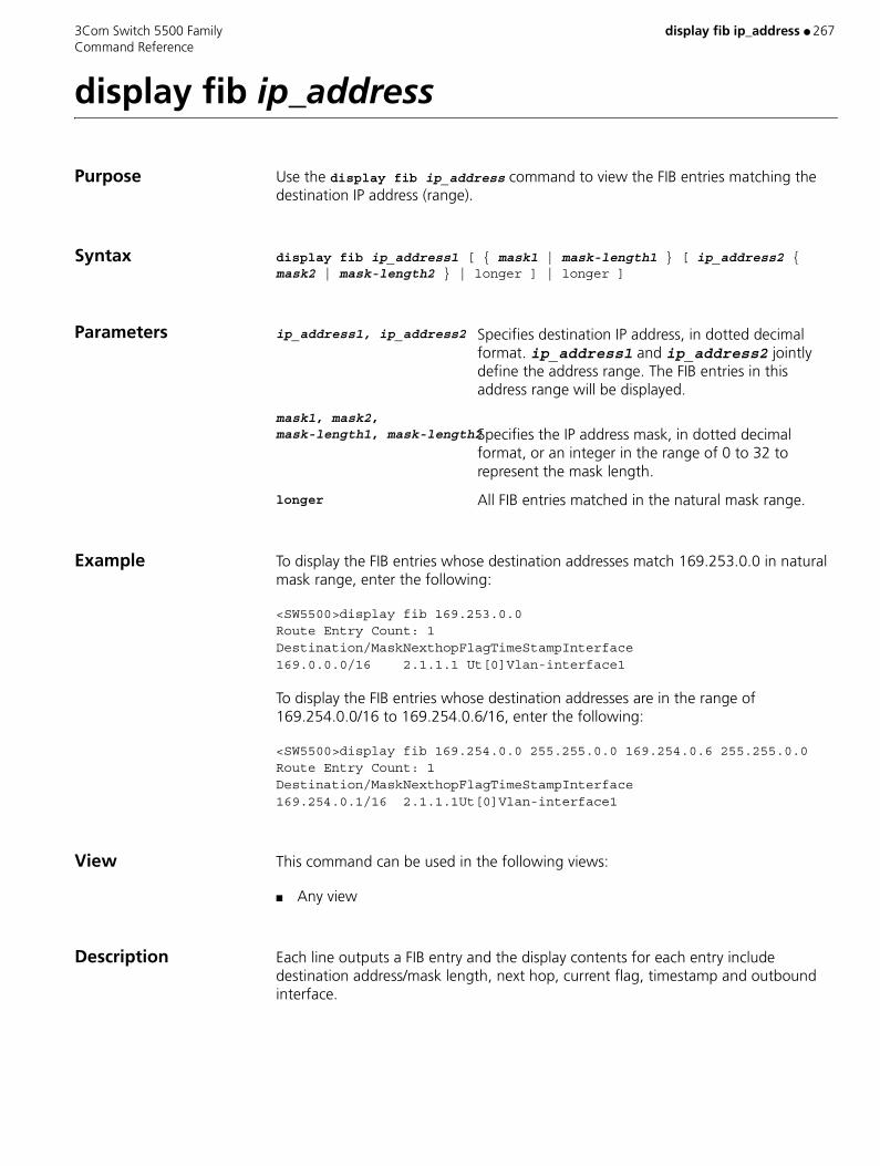
3Com Switch 5500 Family display fib ip_address ● 267 Command Reference
display fib ip_address
Purpose Use the display fib ip_address command to view the FIB entries matching the destination IP address (range).
Syntax display fib ip_address1 [ { mask1 | mask-length1 } [ ip_address2 { mask2 | mask-length2 } | longer ] | longer ]
Parameters ip_address1, ip_address2 Specifies destination IP address, in dotted decimal format. ip_address1 and ip_address2 jointly define the address range. The FIB entries in this address range will be displayed.
mask1, mask2, mask-length1, mask-length2Specifies the IP address mask, in dotted decimal
format, or an integer in the range of 0 to 32 to represent the mask length.
longer All FIB entries matched in the natural mask range.
Example To display the FIB entries whose destination addresses match 169.253.0.0 in natural mask range, enter the following:
<SW5500>display fib 169.253.0.0Route Entry Count: 1Destination/MaskNexthopFlagTimeStampInterface169.0.0.0/16 2.1.1.1 Ut[0]Vlan-interface1
To display the FIB entries whose destination addresses are in the range of 169.254.0.0/16 to 169.254.0.6/16, enter the following:
<SW5500>display fib 169.254.0.0 255.255.0.0 169.254.0.6 255.255.0.0Route Entry Count: 1Destination/MaskNexthopFlagTimeStampInterface169.254.0.1/16 2.1.1.1Ut[0]Vlan-interface1
View This command can be used in the following views:
■ Any view
Description Each line outputs a FIB entry and the display contents for each entry include destination address/mask length, next hop, current flag, timestamp and outbound interface.

268 ● display fib ip-prefix 3Com Switch 5500 Family Command Reference
display fib ip-prefix
Purpose Use the display fib ip-prefix command to view the FIB entries matching the specific prefix list.
Syntax display fib ip-prefix listname
Parameters listname Specifies prefix list name, consisting of a string from 1 to 19 characters long.
Example To display the FIB entries matching prefix list abc0, enter the following:
<SW5500>display fib ip-prefix abc0Route Entry matched by prefix-list abc0:Summary count: 3Destination/MaskNexthopFlagTimeStampInterface127.0.0.0/8 127.0.0.1Ut[0]InLoopBack0127.0.0.1/32 127.0.0.1Ut[0]InLoopBack0169.0.0.0/8 2.1.1.1SUt[0]Vlan-interface1
View This command can be used in the following views:
■ Any view

3Com Switch 5500 Family display fib statistics ● 269 Command Reference
display fib statistics
Purpose Use the display fib statistics command to view the total number of FIB entries.
Syntax display fib statistics [ { begin | include | exclude } text ]
Parametersbegin Specifies the FIB entries from the first one containing
the character string text.
include Specifies only those FIB entries containing the character string text.
exclude Specifies only those FIB entries excluding the character string text.
text String of specific characters.
Example To display the total number of FIB entries, enter the following:
<SW5500>display fib statisticsRoute Entry Count : 30
View This command can be used in the following views:
■ Any view

270 ● display ftm 3Com Switch 5500 Family Command Reference
display ftm
Purpose Use the display ftm information command to display FTM protocol information.
Use the display ftm information command to display the information about FTM protocol, including DDP status, unit ID, Fabric link status, Fabric port status and DDP packet statistics.
Use the display ftm topology-database command to display the information about the fabric topology information database.
Syntax display ftm { information | topology-database }
Parameters information Displays FTM protocol information.
topology-database Displays the information about the fabric topology information database.
Example Display FTM protocol information about the switch.
<S5500> display ftm informationDDP Protocol : disabledFabric VLAN : NONEFabric Auth : NONE
View This command can be used in the following views:
■ Any view
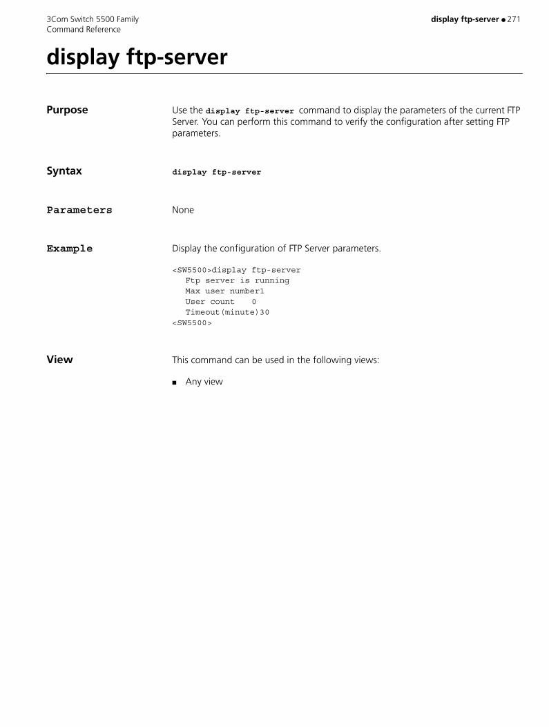
3Com Switch 5500 Family display ftp-server ● 271 Command Reference
display ftp-server
Purpose Use the display ftp-server command to display the parameters of the current FTP Server. You can perform this command to verify the configuration after setting FTP parameters.
Syntax display ftp-server
Parameters None
Example Display the configuration of FTP Server parameters.
<SW5500>display ftp-serverFtp server is runningMax user number1User count 0Timeout(minute)30
<SW5500>
View This command can be used in the following views:
■ Any view

272 ● display ftp-server source-ip 3Com Switch 5500 Family Command Reference
display ftp-server source-ip
Purpose Use the display ftp-server source-ip command to display the source IP address of the FTP server. If no source IP address is specified, 0.0.0.0 is displayed.
Syntax display ftp-server source-ip
Parameters None
Example Display the source IP address of the FTP server.
<S5500> display ftp-server source-ipThe source IP you specified is 192.168.0.1
View This command can be used in the following views:
■ Any view

3Com Switch 5500 Family display ftp source-ip ● 273 Command Reference
display ftp source-ip
Purpose Use the display ftp source-ip command to display the source IP address of the FTP client. If no source IP address is specified, 0.0.0.0 is displayed.
Syntax display ftp source-ip
Parameters None
Example Display the source IP address of the FTP client.
<S5500> display ftp source-ipThe source IP you specified is 192.168.0.1
View This command can be used in the following views:
■ Any view

274 ● display ftp-user 3Com Switch 5500 Family Command Reference
display ftp-user
Purpose Use the display ftp-user command to display the parameters of current FTP user. You can perform this command to examine the configuration after setting FTP parameters.
Syntax display ftp-user
Parameters None
Example Show the configuration of FTP user parameters.
<SW5500>display ftp-user% No ftp user<SW5500>
View This command can be used in the following views:
■ Any view
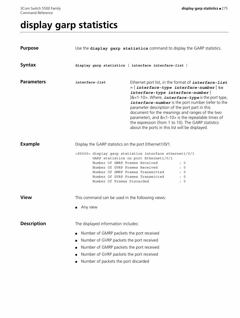
3Com Switch 5500 Family display garp statistics ● 275 Command Reference
display garp statistics
Purpose Use the display garp statistics command to display the GARP statistics.
Syntax display garp statistics [ interface interface-list ]
Parameters interface-list Ethernet port list, in the format of interface-list = { interface-type interface-number [ to interface-type interface-number ] }&<1-10>. Where, interface-type is the port type, interface-number is the port number (refer to the parameter description of the port part in this document for the meanings and ranges of the two parameter), and &<1-10> is the repeatable times of the expression (from 1 to 10). The GARP statistics about the ports in this list will be displayed.
Example Display the GARP statistics on the port Ethernet1/0/1.
<S5500> display garp statistics interface ethernet1/0/1 GARP statistics on port Ethernet1/0/1 Number Of GMRP Frames Received : 0 Number Of GVRP Frames Received : 0 Number Of GMRP Frames Transmitted : 0 Number Of GVRP Frames Transmitted : 0 Number Of Frames Discarded : 0
View This command can be used in the following views:
■ Any view
Description The displayed information includes:
■ Number of GMRP packets the port received
■ Number of GVRP packets the port received
■ Number of GMRP packets the port received
■ Number of GVRP packets the port received
■ Number of packets the port discarded

276 ● display garp timer 3Com Switch 5500 Family Command Reference
display garp timer
Purpose Use the display garp timer command to display the values of the GARP timers.
Syntax display garp timer [ interface interface-list ]
Parameters interface-list Ethernet port list, in the format of interface-list = { interface-type interface-number [ to interface-type interface-number ] }&<1-10>. Where, interface-type is the port type, interface-number is the port number (refer to the parameter description of the port part in this document for the meanings and ranges of the two parameter), and &<1-10> is the repeatable times of the expression (from 1 to 10). The timer information about the ports in this list will be displayed.
Example Display the values of GARP timers of the port Ethernet1/0/1.
<S5500> display garp timer interface ethernet1/0/1 GARP timers on port Ethernet1/0/1
Garp Join Time : 20 centiseconds Garp Leave Time : 60 centiseconds Garp LeaveAll Time : 1000 centiseconds Garp Hold Time : 10 centiseconds
View This command can be used in the following views:
■ Any view
Description The displayed information includes:
■ Value of the Join timer
■ Value of the Leave timer
■ Value of the LeaveAll timer
■ Value of the Hold timer
Related Commands ■ garp timer
■ garp timer leaveall
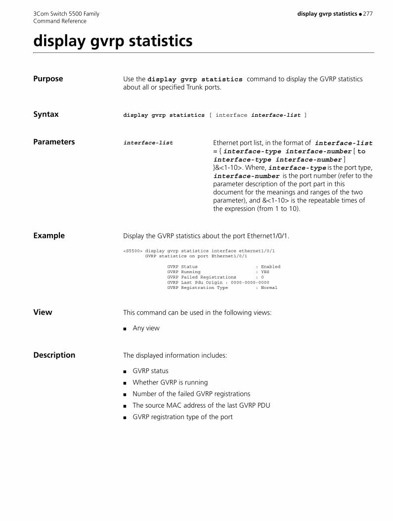
3Com Switch 5500 Family display gvrp statistics ● 277 Command Reference
display gvrp statistics
Purpose Use the display gvrp statistics command to display the GVRP statistics about all or specified Trunk ports.
Syntax display gvrp statistics [ interface interface-list ]
Parameters interface-list Ethernet port list, in the format of interface-list = { interface-type interface-number [ to interface-type interface-number ] }&<1-10>. Where, interface-type is the port type, interface-number is the port number (refer to the parameter description of the port part in this document for the meanings and ranges of the two parameter), and &<1-10> is the repeatable times of the expression (from 1 to 10).
Example Display the GVRP statistics about the port Ethernet1/0/1.
<S5500> display gvrp statistics interface ethernet1/0/1 GVRP statistics on port Ethernet1/0/1
GVRP Status : Enabled GVRP Running : YES GVRP Failed Registrations : 0 GVRP Last Pdu Origin : 0000-0000-0000 GVRP Registration Type : Normal
View This command can be used in the following views:
■ Any view
Description The displayed information includes:
■ GVRP status
■ Whether GVRP is running
■ Number of the failed GVRP registrations
■ The source MAC address of the last GVRP PDU
■ GVRP registration type of the port

278 ● display gvrp status 3Com Switch 5500 Family Command Reference
display gvrp status
Purpose Use the display gvrp status command to display the enable/disable status of global GVRP.
Syntax display gvrp status
Parameters None
Example Display the enable/disable status of global GVRP.
<S5500> display gvrp statusGVRP is enabledThe above information indicates GVRP is enabled globally.
View This command can be used in the following views:
■ Any view
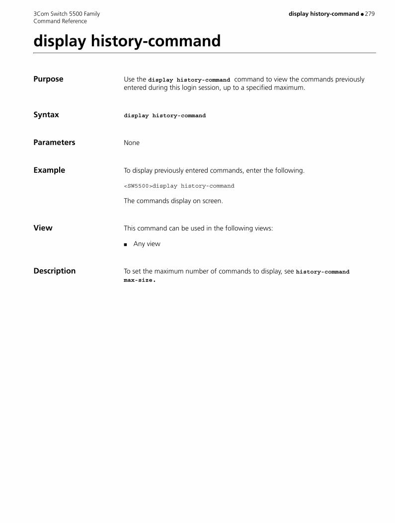
3Com Switch 5500 Family display history-command ● 279 Command Reference
display history-command
Purpose Use the display history-command command to view the commands previously entered during this login session, up to a specified maximum.
Syntax display history-command
Parameters None
Example To display previously entered commands, enter the following.
<SW5500>display history-command
The commands display on screen.
View This command can be used in the following views:
■ Any view
Description To set the maximum number of commands to display, see history-command max-size.

280 ● display hwtacacs 3Com Switch 5500 Family Command Reference
display hwtacacs
Purpose Use the display hwtacacs command to view configuration information of one or all HWTACACS schemes.
Syntax display hwtacacs [ hwtacacs-scheme-name ]
Parameters hwtacacs-scheme-name: Scheme name of the HWTACACS server. Valid values are a string of 1 to 32 case-insensitive characters, excluding "?". If this argument is null, configuration information of all HWTACACS schemes are displayed.
Default By default, configuration information of all HWTACACS schemes is displayed.
Example Display the configuration information of the HWTACACS scheme gy.
<S5500> display hwtacacs gy-------------------------------------------------------------------- HWTACACS-server template name : gy Primary-authentication-server : 172.31.1.11:49 Primary-authorization-server : 172.31.1.11:49 Primary-accounting-server : 172.31.1.11:49 Secondary-authentication-server : 0.0.0.0:0 Secondary-authorization-server : 0.0.0.0:0 Secondary-accounting-server : 0.0.0.0:0 Current-authentication-server : 172.31.1.11:49 Current-authorization-server : 172.31.1.11:49 Current-accounting-server : 172.31.1.11:49 Source-IP-address : 0.0.0.0 key authentication : 790131 key authorization : 790131 key accounting : 790131 Quiet-interval(min) : 5 Response-timeout-Interval(sec) : 5 Domain-included : No Traffic-unit : B Packet traffic-unit : one-packet
View This command can be used in the following views:
■ Any view
Related Command hwtacacs scheme

3Com Switch 5500 Family display icmp statistics ● 281 Command Reference
display icmp statistics
Purpose Use the display icmp statistics command to view the statistics information about ICMP packets.
Syntax display icmp statistics
Parameters None
Example To view statistics about ICMP packets, enter the following:
<SW5500> display icmp statistics Input: bad formats 0 bad checksum 0 echo 5 destination unreachable 0 source quench 0 redirects 0 echo reply 10 parameter problem 0 timestamp 0 information request 0 mask requests 0 mask replies 0 time exceeded 0 Output:echo 10 destination unreachable 0 source quench 0 redirects 0 echo reply 5 parameter problem 0 timestamp 0 information reply 0 mask requests 0 mask replies 0 time exceeded 0
View This command can be used in the following views:
■ Any view
Table 22 Output Description of the display icmp statistics command
Field Description
bad formats Number of input packets in bad format
bad checksum Number of input packets with wrong checksum
echo Number of input/output echo request packets
destination unreachable Number of input/output packets with unreachable destination
source quench Number of input/output source quench packets
redirects Number of input/output redirected packets
echo reply Number of input/output echo reply packets
parameter problem Number of input/output packets with parameter problem
timestamp Number of input/output timestamp packets
information request Number of input information request packets
mask requests Number of input/output mask request packets
mask replies Number of input/output mask reply packets
information reply Number of output information reply packets
time exceeded Number of time exceeded packets

282 ● display icmp statistics 3Com Switch 5500 Family Command Reference
Related Commands ■ display interface VLAN-interface
■ reset ip statistics

3Com Switch 5500 Family display igmp group ● 283 Command Reference
display igmp group
Purpose Use the display igmp group command to view the member information of the IGMP multicast group.
Syntax display igmp group [ group-address | interface interface-type interface-number ]
Parameters group-address Address of the multicast group.
interface-type interface-number Interface type and interface number of the router, used
to specify the specific interface.
Example View the member information of multicast group in the system.
<SW5500>display igmp groupLoopBack0 (20.20.20.20): Total 3 IGMP Groups reported: Group Address Last Reporter Uptime Expires 225.1.1.1 20.20.20.20 00:02:04 00:01:15 225.1.1.3 20.20.20.20 00:02:04 00:01:15 225.1.1.2 20.20.20.20 00:02:04 00:01:17
View This command can be used in the following views:
■ Any View
Description You can specify to show the information of a group or the member information of the multicast group on an interface. The information displayed contains the multicast groups that are joined by the downstream hosts through IGMP or through command line.
Related Command igmp host-join
Table 23 Output Display of the display igmp group command
Field Description
Group address Multicast group address
Last Reporter The last host reporting to join in the multicast group
Uptime Time passed since multicast group is discovered (hh: mm: ss)
Expires Specifies when the member will be removed from the multicast group (hh: mm: ss).
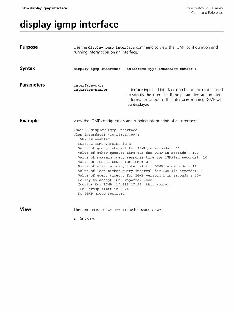
284 ● display igmp interface 3Com Switch 5500 Family Command Reference
display igmp interface
Purpose Use the display igmp interface command to view the IGMP configuration and running information on an interface.
Syntax display igmp interface [ interface-type interface-number ]
Parameters interface-type interface-number Interface type and interface number of the router, used
to specify the interface. If the parameters are omitted, information about all the interfaces running IGMP will be displayed.
Example View the IGMP configuration and running information of all interfaces.
<SW5500>display igmp interfaceVlan-interface1 (10.153.17.99): IGMP is enabled Current IGMP version is 2 Value of query interval for IGMP(in seconds): 60 Value of other querier time out for IGMP(in seconds): 120 Value of maximum query response time for IGMP(in seconds): 10 Value of robust count for IGMP: 2 Value of startup query interval for IGMP(in seconds): 15 Value of last member query interval for IGMP(in seconds): 1 Value of query timeout for IGMP version 1(in seconds): 400 Policy to accept IGMP reports: none Querier for IGMP: 10.153.17.99 (this router) IGMP group limit is 1024 No IGMP group reported
View This command can be used in the following views:
■ Any view

3Com Switch 5500 Family display igmp-snooping configuration ● 285 Command Reference
display igmp-snooping configuration
Purpose Use the display igmp-snooping configuration command to display the configuration information about IGMP Snooping.
Syntax display igmp-snooping configuration
Parameters None
Example Display the configuration information about IGMP Snooping on the switch.
<S5500> display igmp-snooping configurationEnable IGMP-Snooping.The router port timeout is 105 second(s).The max response timeout is 1 second(s).The host port timeout is 260 second(s).
The above information shows: IGMP Snooping has already been enabled, the aging time of the router port is 105 seconds, the maximum query response time is one second, and the aging time of multicast member ports is 260 seconds.
View This command can be used in the following views:
■ Any view
Description When IGMP Snooping is enabled on the switch, this command displays the following information: IGMP Snooping state, aging time of the router port, maximum query response time, and aging time of multicast member ports.
Related Command igmp-snooping
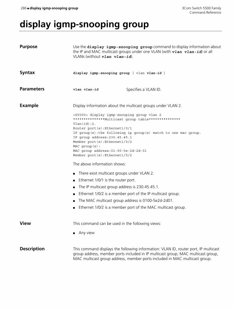
286 ● display igmp-snooping group 3Com Switch 5500 Family Command Reference
display igmp-snooping group
Purpose Use the display igmp-snooping group command to display information about the IP and MAC multicast groups under one VLAN (with vlan vlan-id) or all VLANs (without vlan vlan-id).
Syntax display igmp-snooping group [ vlan vlan-id ]
Parameters vlan vlan-id Specifies a VLAN ID.
Example Display information about the multicast groups under VLAN 2.
<S5500> display igmp-snooping group vlan 2***************Multicast group table***************Vlan(id):2.Router port(s):Ethernet1/0/1IP group(s):the following ip group(s) match to one mac group.IP group address:230.45.45.1Member port(s):Ethernet1/0/2MAC group(s):MAC group address:01-00-5e-2d-2d-01Member port(s):Ethernet1/0/2
The above information shows:
■ There exist multicast groups under VLAN 2.
■ Ethernet 1/0/1 is the router port.
■ The IP multicast group address is 230.45.45.1.
■ Ethernet 1/0/2 is a member port of the IP multicast group.
■ The MAC multicast group address is 0100-5e2d-2d01.
■ Ethernet 1/0/2 is a member port of the MAC multicast group.
View This command can be used in the following views:
■ Any view
Description This command displays the following information: VLAN ID, router port, IP multicast group address, member ports included in IP multicast group, MAC multicast group, MAC multicast group address, member ports included in MAC multicast group.

3Com Switch 5500 Family display igmp-snooping statistics ● 287 Command Reference
display igmp-snooping statistics
Purpose Use the display igmp-snooping statistics command to display the message statistics about IGMP Snooping.
Syntax display igmp-snooping statistics
Parameters None
Example Display the message statistics about IGMP Snooping.
<S5500> display igmp-snooping statisticsReceived IGMP general query packet(s) number:0.Received IGMP specific query packet(s) number:0.Received IGMP V1 report packet(s) number:0.Received IGMP V2 report packet(s) number:0.Received IGMP leave packet(s) number:0.Received error IGMP packet(s) number:0.Sent IGMP specific query packet(s) number:0.
The above information shows that IGMP Snooping has received:
■ Zero IGMP general query message
■ Zero IGMP group-specific query message
■ Zero IGMP V1 report message
■ Zero IGMP V2 report message
■ Zero IGMP leave message
■ Zero IGMP error message
And IGMP Snooping has sent:
■ Zero IGMP group-specific query message
View This command can be used in the following views:
■ Any view
Description This command displays the following information: the numbers of the IGMP general query messages, IGMP group-specific query messages, IGMP V1 report messages, IGMP V2 report messages, IGMP leave messages and error IGMP messages received, and the number of the IGMP group-specific query messages sent.
Related Command igmp-snooping
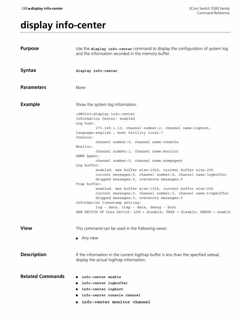
288 ● display info-center 3Com Switch 5500 Family Command Reference
display info-center
Purpose Use the display info-center command to display the configuration of system log and the information recorded in the memory buffer.
Syntax display info-center
Parameters None
Example Show the system log information.
<SW5500>display info-center Information Center: enabledLog host: 173.168.1.10, channel number:2, channel name:loghost,language:english , host facility local:7Console: channel number:0, channel name:consoleMonitor: channel number:1, channel name:monitorSNMP Agent: channel number:5, channel name:snmpagentLog buffer: enabled, max buffer size:1024, current buffer size:256 current messages:6, channel number:4, channel name:logbuffer dropped messages:0, overwrote messages:0Trap buffer: enabled, max buffer size:1024, current buffer size:256 current messages:0, channel number:3, channel name:trapbuffer dropped messages:0, overwrote messages:0Information timestamp setting: log - date, trap - date, debug - bootXRN SWITCH OF this Device: LOG = disable; TRAP = disable; DEBUG = enable
View This command can be used in the following views:
■ Any view
Description If the information in the current log/trap buffer is less than the specified sizeval, display the actual log/trap information.
Related Commands ■ info-center enable
■ info-center logbuffer
■ info-center loghost
■ info-center console channel
■ info-center monitor channel
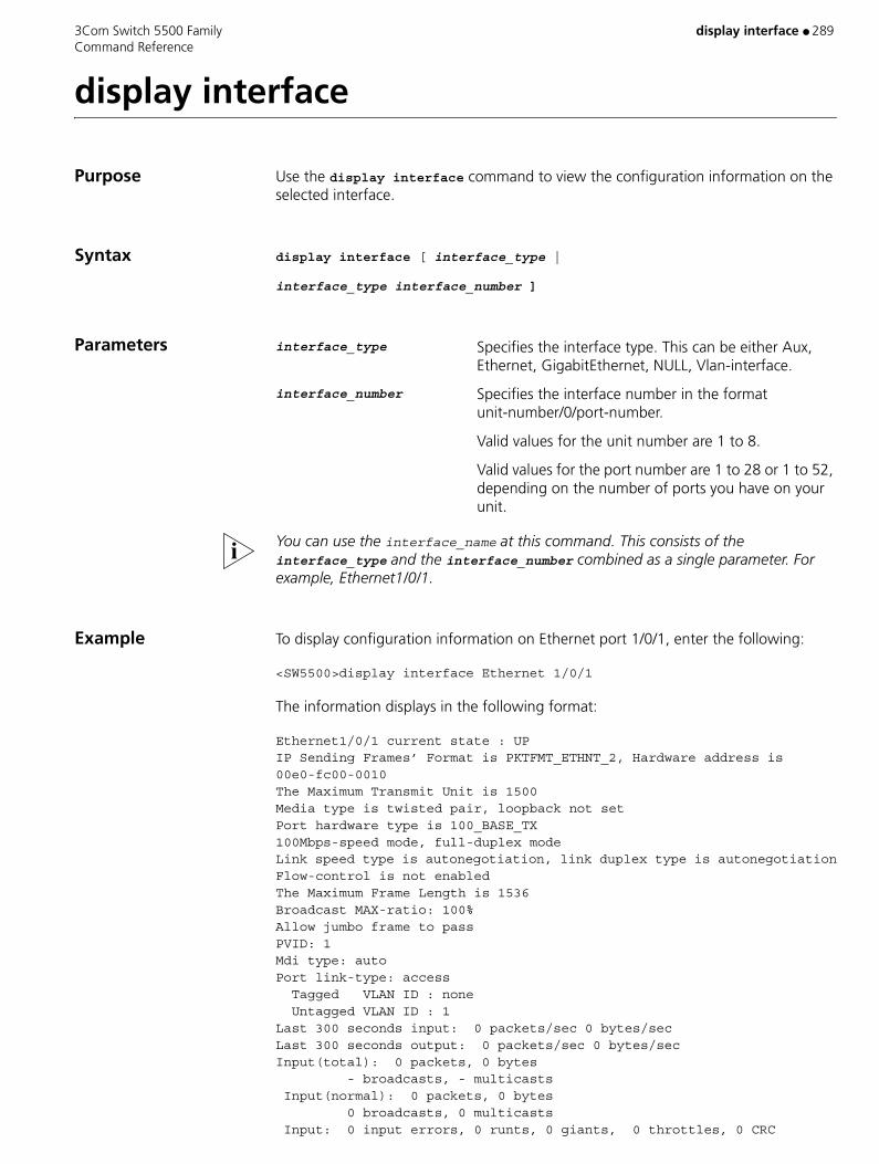
3Com Switch 5500 Family display interface ● 289 Command Reference
display interface
Purpose Use the display interface command to view the configuration information on the selected interface.
Syntax display interface [ interface_type |
interface_type interface_number ]
Parameters interface_type Specifies the interface type. This can be either Aux, Ethernet, GigabitEthernet, NULL, Vlan-interface.
interface_number Specifies the interface number in the format unit-number/0/port-number.
Valid values for the unit number are 1 to 8.
Valid values for the port number are 1 to 28 or 1 to 52, depending on the number of ports you have on your unit.
You can use the interface_name at this command. This consists of the interface_type and the interface_number combined as a single parameter. For example, Ethernet1/0/1.
Example To display configuration information on Ethernet port 1/0/1, enter the following:
<SW5500>display interface Ethernet 1/0/1
The information displays in the following format:
Ethernet1/0/1 current state : UPIP Sending Frames’ Format is PKTFMT_ETHNT_2, Hardware address is 00e0-fc00-0010The Maximum Transmit Unit is 1500Media type is twisted pair, loopback not setPort hardware type is 100_BASE_TX100Mbps-speed mode, full-duplex modeLink speed type is autonegotiation, link duplex type is autonegotiationFlow-control is not enabledThe Maximum Frame Length is 1536Broadcast MAX-ratio: 100%Allow jumbo frame to passPVID: 1Mdi type: autoPort link-type: access Tagged VLAN ID : none Untagged VLAN ID : 1Last 300 seconds input: 0 packets/sec 0 bytes/secLast 300 seconds output: 0 packets/sec 0 bytes/secInput(total): 0 packets, 0 bytes - broadcasts, - multicasts Input(normal): 0 packets, 0 bytes 0 broadcasts, 0 multicasts Input: 0 input errors, 0 runts, 0 giants, 0 throttles, 0 CRC
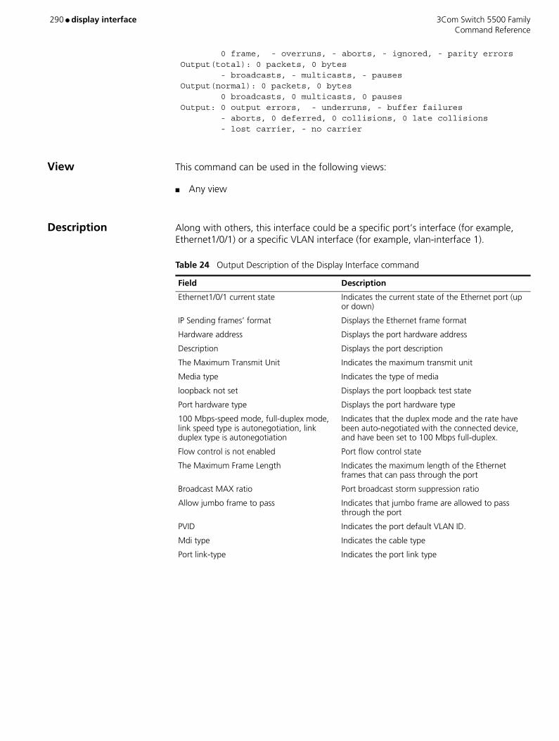
290 ● display interface 3Com Switch 5500 Family Command Reference
0 frame, - overruns, - aborts, - ignored, - parity errors Output(total): 0 packets, 0 bytes - broadcasts, - multicasts, - pauses Output(normal): 0 packets, 0 bytes 0 broadcasts, 0 multicasts, 0 pauses Output: 0 output errors, - underruns, - buffer failures - aborts, 0 deferred, 0 collisions, 0 late collisions - lost carrier, - no carrier
View This command can be used in the following views:
■ Any view
Description Along with others, this interface could be a specific port’s interface (for example, Ethernet1/0/1) or a specific VLAN interface (for example, vlan-interface 1).
Table 24 Output Description of the Display Interface command
Field Description
Ethernet1/0/1 current state Indicates the current state of the Ethernet port (up or down)
IP Sending frames’ format Displays the Ethernet frame format
Hardware address Displays the port hardware address
Description Displays the port description
The Maximum Transmit Unit Indicates the maximum transmit unit
Media type Indicates the type of media
loopback not set Displays the port loopback test state
Port hardware type Displays the port hardware type
100 Mbps-speed mode, full-duplex mode, link speed type is autonegotiation, link duplex type is autonegotiation
Indicates that the duplex mode and the rate have been auto-negotiated with the connected device, and have been set to 100 Mbps full-duplex.
Flow control is not enabled Port flow control state
The Maximum Frame Length Indicates the maximum length of the Ethernet frames that can pass through the port
Broadcast MAX ratio Port broadcast storm suppression ratio
Allow jumbo frame to pass Indicates that jumbo frame are allowed to pass through the port
PVID Indicates the port default VLAN ID.
Mdi type Indicates the cable type
Port link-type Indicates the port link type
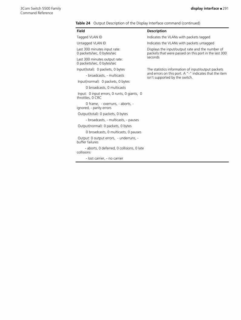
3Com Switch 5500 Family display interface ● 291 Command Reference
Tagged VLAN ID Indicates the VLANs with packets tagged
Untagged VLAN ID Indicates the VLANs with packets untagged
Last 300 minutes input rate: 0 packets/sec, 0 bytes/sec
Last 300 minutes output rate: 0 packets/sec, 0 bytes/sec
Displays the input/output rate and the number of packets that were passed on this port in the last 300 seconds
Input(total): 0 packets, 0 bytes
- broadcasts, - multicasts
Input(normal): 0 packets, 0 bytes
0 broadcasts, 0 multicasts
Input: 0 input errors, 0 runts, 0 giants, 0 throttles, 0 CRC
0 frame, - overruns, - aborts, - ignored, - parity errors
Output(total): 0 packets, 0 bytes
- broadcasts, - multicasts, - pauses
Output(normal): 0 packets, 0 bytes
0 broadcasts, 0 multicasts, 0 pauses
Output: 0 output errors, - underruns, - buffer failures
- aborts, 0 deferred, 0 collisions, 0 late collisions
- lost carrier, - no carrier
The statistics information of input/output packets and errors on this port. A “-” indicates that the item isn't supported by the switch.
Table 24 Output Description of the Display Interface command (continued)
Field Description
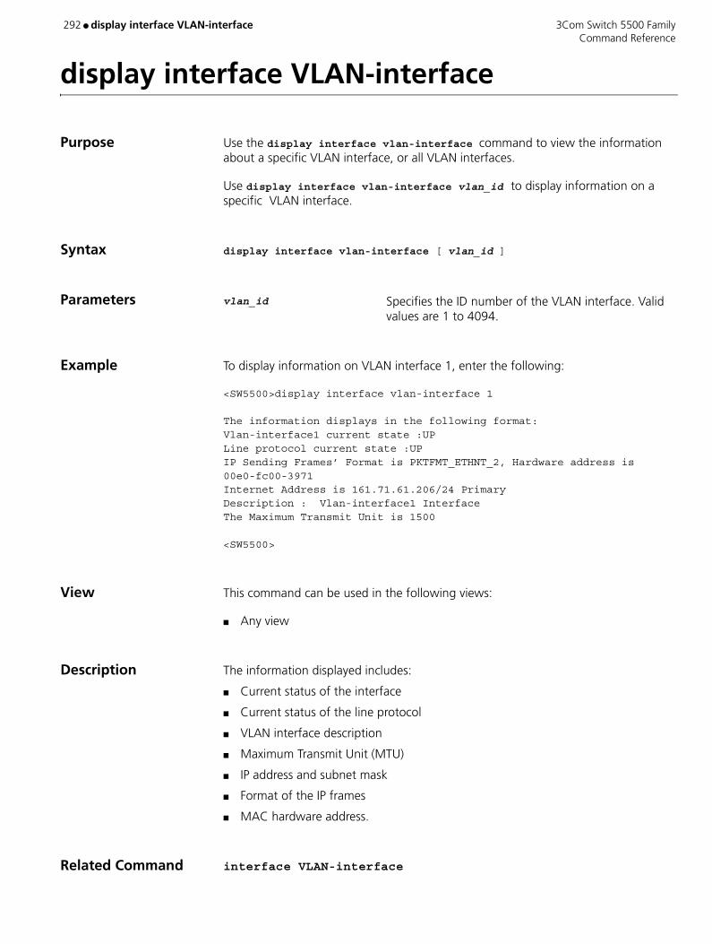
292 ● display interface VLAN-interface 3Com Switch 5500 Family Command Reference
display interface VLAN-interface
Purpose Use the display interface vlan-interface command to view the information about a specific VLAN interface, or all VLAN interfaces.
Use display interface vlan-interface vlan_id to display information on a specific VLAN interface.
Syntax display interface vlan-interface [ vlan_id ]
Parameters vlan_id Specifies the ID number of the VLAN interface. Valid values are 1 to 4094.
Example To display information on VLAN interface 1, enter the following:
<SW5500>display interface vlan-interface 1
The information displays in the following format:Vlan-interface1 current state :UPLine protocol current state :UPIP Sending Frames’ Format is PKTFMT_ETHNT_2, Hardware address is 00e0-fc00-3971Internet Address is 161.71.61.206/24 PrimaryDescription : Vlan-interface1 InterfaceThe Maximum Transmit Unit is 1500
<SW5500>
View This command can be used in the following views:
■ Any view
Description The information displayed includes:
■ Current status of the interface
■ Current status of the line protocol
■ VLAN interface description
■ Maximum Transmit Unit (MTU)
■ IP address and subnet mask
■ Format of the IP frames
■ MAC hardware address.
Related Command interface VLAN-interface

3Com Switch 5500 Family display ip host ● 293 Command Reference
display ip host
Purpose Use the display ip host command to display all host names and their corresponding IP addresses.
Syntax display ip host
Parameters None
Example To display all host names and their corresponding IP addresses, type the following:
<SW5500>display ip host
The information displays in the following format:
Host Age FlagsAddressMy 0 static1.1.1.1Aa 0 static2.2.2.4
View This command can be used in the following views:
■ Any view
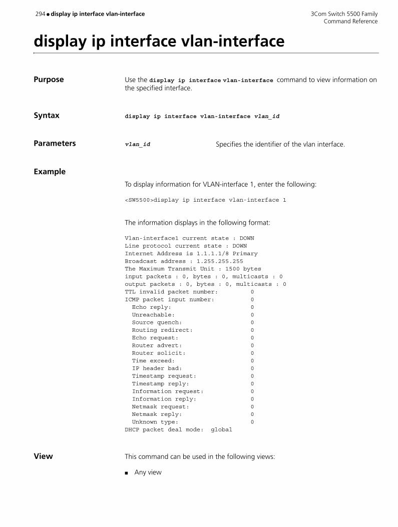
294 ● display ip interface vlan-interface 3Com Switch 5500 Family Command Reference
display ip interface vlan-interface
Purpose Use the display ip interface vlan-interface command to view information on the specified interface.
Syntax display ip interface vlan-interface vlan_id
Parameters vlan_id Specifies the identifier of the vlan interface.
Example
To display information for VLAN-interface 1, enter the following:
<SW5500>display ip interface vlan-interface 1
The information displays in the following format:
Vlan-interface1 current state : DOWNLine protocol current state : DOWNInternet Address is 1.1.1.1/8 PrimaryBroadcast address : 1.255.255.255The Maximum Transmit Unit : 1500 bytesinput packets : 0, bytes : 0, multicasts : 0output packets : 0, bytes : 0, multicasts : 0TTL invalid packet number: 0ICMP packet input number: 0 Echo reply: 0 Unreachable: 0 Source quench: 0 Routing redirect: 0 Echo request: 0 Router advert: 0 Router solicit: 0 Time exceed: 0 IP header bad: 0 Timestamp request: 0 Timestamp reply: 0 Information request: 0 Information reply: 0 Netmask request: 0 Netmask reply: 0 Unknown type: 0DHCP packet deal mode: global
View This command can be used in the following views:
■ Any view

3Com Switch 5500 Family display ip ip-prefix ● 295 Command Reference
display ip ip-prefix
Purpose Use the display ip ip-prefix command to view the address prefix list.
Syntax display ip ip-prefix [ ip_prefix_name ]
Parameters ip_prefix_name Specifies displayed address prefix list name.
Example Display the information of the address prefix list named to p1.
<SW5500>display ip ip-prefix p1name index conditions ip-prefix / mask GE LEp1 10 permit 10.1.0.0/16 17 18
View This command can be used in the following views:
■ Any view
Related Command ip ip-prefix
Table 25 Output Description of the display ip-ip prefix command
Field Description
name Name of ip-prefix
index Internal sequence number of ip-prefix
conditions Mode: permit or deny
ip-prefix Address and network segment length of ip-prefix
GE Greater-equal value of ip-prefix network segment length
LE Less-equal value of ip-prefix network segment length
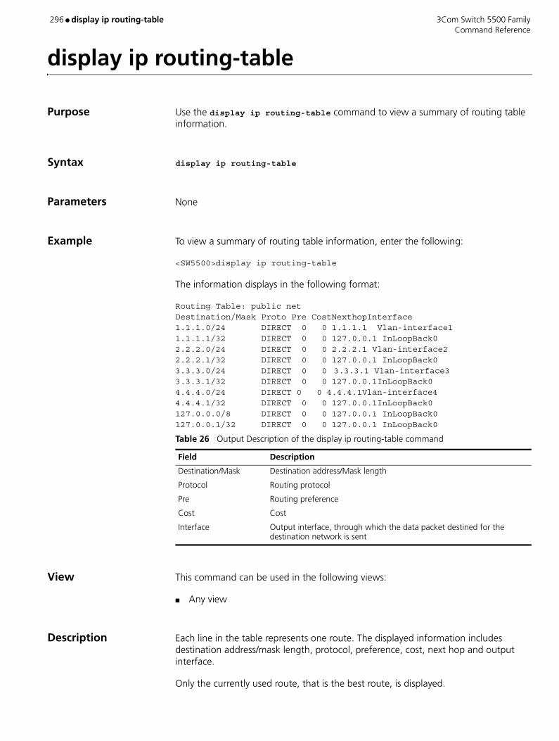
296 ● display ip routing-table 3Com Switch 5500 Family Command Reference
display ip routing-table
Purpose Use the display ip routing-table command to view a summary of routing table information.
Syntax display ip routing-table
Parameters None
Example To view a summary of routing table information, enter the following:
<SW5500>display ip routing-table
The information displays in the following format:
Routing Table: public netDestination/Mask Proto Pre CostNexthopInterface1.1.1.0/24 DIRECT 0 0 1.1.1.1 Vlan-interface11.1.1.1/32 DIRECT 0 0 127.0.0.1 InLoopBack02.2.2.0/24 DIRECT 0 0 2.2.2.1 Vlan-interface22.2.2.1/32 DIRECT 0 0 127.0.0.1 InLoopBack03.3.3.0/24 DIRECT 0 0 3.3.3.1 Vlan-interface33.3.3.1/32 DIRECT 0 0 127.0.0.1InLoopBack04.4.4.0/24 DIRECT 0 0 4.4.4.1Vlan-interface44.4.4.1/32 DIRECT 0 0 127.0.0.1InLoopBack0127.0.0.0/8 DIRECT 0 0 127.0.0.1 InLoopBack0127.0.0.1/32 DIRECT 0 0 127.0.0.1 InLoopBack0
View This command can be used in the following views:
■ Any view
Description Each line in the table represents one route. The displayed information includes destination address/mask length, protocol, preference, cost, next hop and output interface.
Only the currently used route, that is the best route, is displayed.
Table 26 Output Description of the display ip routing-table command
Field Description
Destination/Mask Destination address/Mask length
Protocol Routing protocol
Pre Routing preference
Cost Cost
Interface Output interface, through which the data packet destined for the destination network is sent
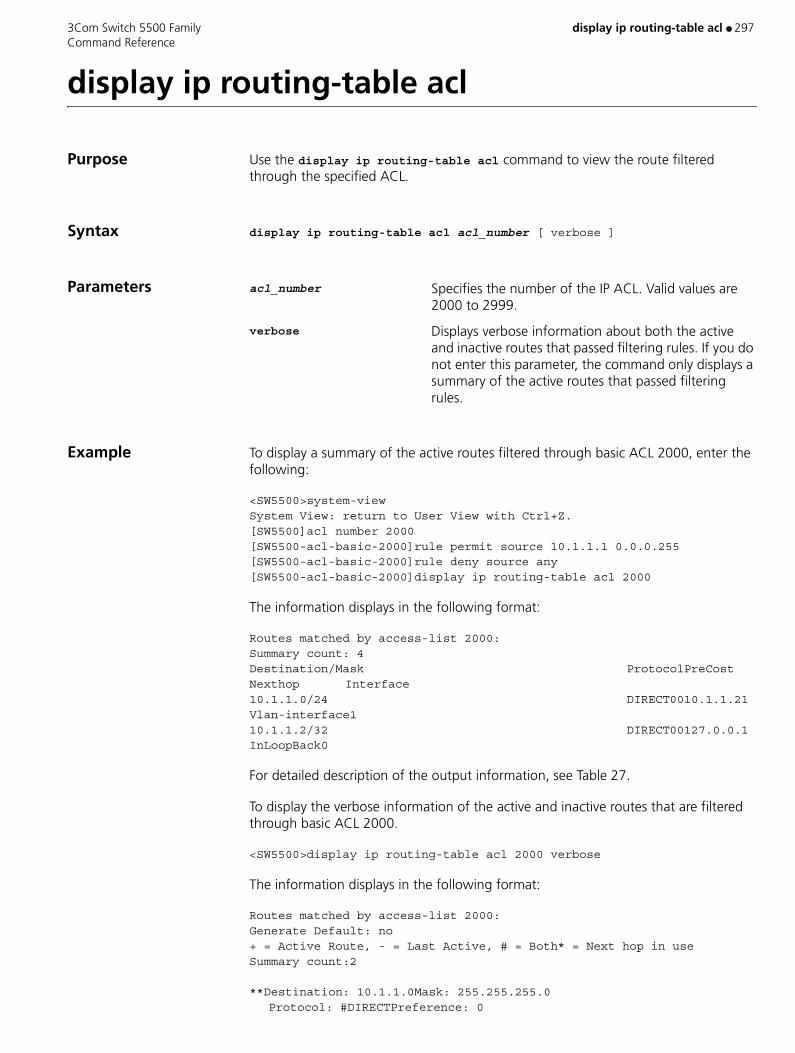
3Com Switch 5500 Family display ip routing-table acl ● 297 Command Reference
display ip routing-table acl
Purpose Use the display ip routing-table acl command to view the route filtered through the specified ACL.
Syntax display ip routing-table acl acl_number [ verbose ]
Parameters acl_number Specifies the number of the IP ACL. Valid values are 2000 to 2999.
verbose Displays verbose information about both the active and inactive routes that passed filtering rules. If you do not enter this parameter, the command only displays a summary of the active routes that passed filtering rules.
Example To display a summary of the active routes filtered through basic ACL 2000, enter the following:
<SW5500>system-viewSystem View: return to User View with Ctrl+Z.[SW5500]acl number 2000[SW5500-acl-basic-2000]rule permit source 10.1.1.1 0.0.0.255[SW5500-acl-basic-2000]rule deny source any[SW5500-acl-basic-2000]display ip routing-table acl 2000
The information displays in the following format:
Routes matched by access-list 2000:Summary count: 4Destination/Mask ProtocolPreCost Nexthop Interface10.1.1.0/24 DIRECT0010.1.1.21 Vlan-interface110.1.1.2/32 DIRECT00127.0.0.1InLoopBack0
For detailed description of the output information, see Table 27.
To display the verbose information of the active and inactive routes that are filtered through basic ACL 2000.
<SW5500>display ip routing-table acl 2000 verbose
The information displays in the following format:
Routes matched by access-list 2000:Generate Default: no+ = Active Route, - = Last Active, # = Both* = Next hop in useSummary count:2
**Destination: 10.1.1.0Mask: 255.255.255.0Protocol: #DIRECTPreference: 0
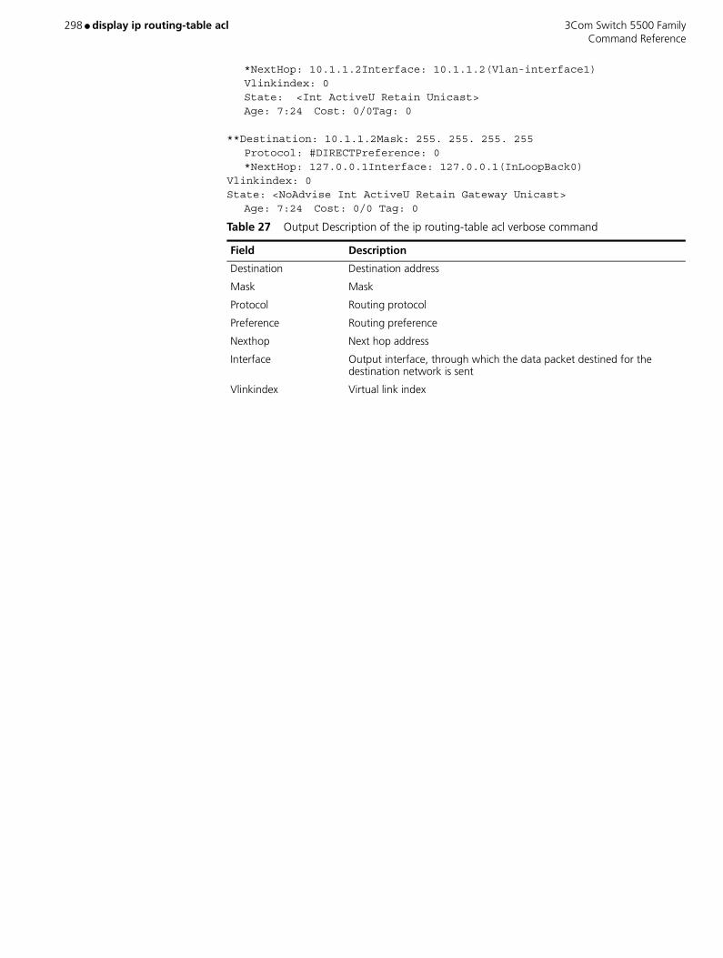
298 ● display ip routing-table acl 3Com Switch 5500 Family Command Reference
*NextHop: 10.1.1.2Interface: 10.1.1.2(Vlan-interface1)Vlinkindex: 0State: <Int ActiveU Retain Unicast>Age: 7:24 Cost: 0/0Tag: 0
**Destination: 10.1.1.2Mask: 255. 255. 255. 255Protocol: #DIRECTPreference: 0*NextHop: 127.0.0.1Interface: 127.0.0.1(InLoopBack0)
Vlinkindex: 0State: <NoAdvise Int ActiveU Retain Gateway Unicast>
Age: 7:24 Cost: 0/0 Tag: 0
Table 27 Output Description of the ip routing-table acl verbose command
Field Description
Destination Destination address
Mask Mask
Protocol Routing protocol
Preference Routing preference
Nexthop Next hop address
Interface Output interface, through which the data packet destined for the destination network is sent
Vlinkindex Virtual link index
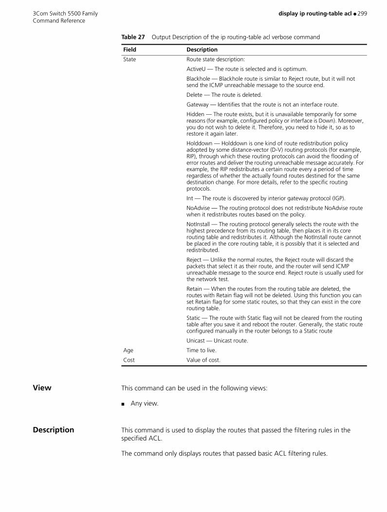
3Com Switch 5500 Family display ip routing-table acl ● 299 Command Reference
View This command can be used in the following views:
■ Any view.
Description This command is used to display the routes that passed the filtering rules in the specified ACL.
The command only displays routes that passed basic ACL filtering rules.
State Route state description:
ActiveU — The route is selected and is optimum.
Blackhole — Blackhole route is similar to Reject route, but it will not send the ICMP unreachable message to the source end.
Delete — The route is deleted.
Gateway — Identifies that the route is not an interface route.
Hidden — The route exists, but it is unavailable temporarily for some reasons (for example, configured policy or interface is Down). Moreover, you do not wish to delete it. Therefore, you need to hide it, so as to restore it again later.
Holddown — Holddown is one kind of route redistribution policy adopted by some distance-vector (D-V) routing protocols (for example, RIP), through which these routing protocols can avoid the flooding of error routes and deliver the routing unreachable message accurately. For example, the RIP redistributes a certain route every a period of time regardless of whether the actually found routes destined for the same destination change. For more details, refer to the specific routing protocols.
Int — The route is discovered by interior gateway protocol (IGP).
NoAdvise — The routing protocol does not redistribute NoAdvise route when it redistributes routes based on the policy.
NotInstall — The routing protocol generally selects the route with the highest precedence from its routing table, then places it in its core routing table and redistributes it. Although the NotInstall route cannot be placed in the core routing table, it is possibly that it is selected and redistributed.
Reject — Unlike the normal routes, the Reject route will discard the packets that select it as their route, and the router will send ICMP unreachable message to the source end. Reject route is usually used for the network test.
Retain — When the routes from the routing table are deleted, the routes with Retain flag will not be deleted. Using this function you can set Retain flag for some static routes, so that they can exist in the core routing table.
Static — The route with Static flag will not be cleared from the routing table after you save it and reboot the router. Generally, the static route configured manually in the router belongs to a Static route
Unicast — Unicast route.
Age Time to live.
Cost Value of cost.
Table 27 Output Description of the ip routing-table acl verbose command
Field Description

300 ● display ip routing-table ip_address 3Com Switch 5500 Family Command Reference
display ip routing-table ip_address
Purpose Use the display ip routing-table ip_address command to view routing information for a specific IP address, and you can also choose the type of information to display.
Use the display ip routing-table ip_address mask command to display the route that matches the specified IP destination address and subnet mask.
Use the display ip routing-table ip_address longer-match command to display all destination address routes that match destination IP addresses in natural mask range.
Use the display ip routing-table ip_address verbose command to display verbose information about both active and inactive routes.
Syntax display ip routing-table ip_address [ mask ] [ longer-match ] [ verbose ]
Parameters ip_address Specifies the destination IP address.
mask Specifies either the IP subnet mask (in x.x.x.x format), or the subnet mask length (in the range 0 to 32). Optional.
longer-match Displays an address route that matches the destination IP address in natural mask range. Optional.
verbose Displays verbose information about both active and inactive routes. Without this parameter, this command only displays a summary of active routes. Optional.
Example There is corresponding route in natural mask range. Display the summary.
<SW5500>display ip routing-table 169.0.0.0Routing Tables:Summary count:1Destination/MaskProtoPreCost NexthopInterface169.0.0.0/16 Static6002.1.1.1LoopBack1
There are corresponding routes in the natural mask range. Display the detailed information.
<SW5500>display ip routing-table 169.0.0.0 verboseRouting Tables:Generate Default: no+ = Active Route, - = Last Active, # = Both* = Next hop in useSummary count:2**Destination: 169.0.0.0Mask: 255.0.0.0
Protocol: #StaticPreference: 60*NextHop: 2.1.1.1Interface: 2.1.1.1(LoopBack1)Vlinkindex: 0State: <Int ActiveU Static Unicast>Age: 3:47 Cost: 0/0
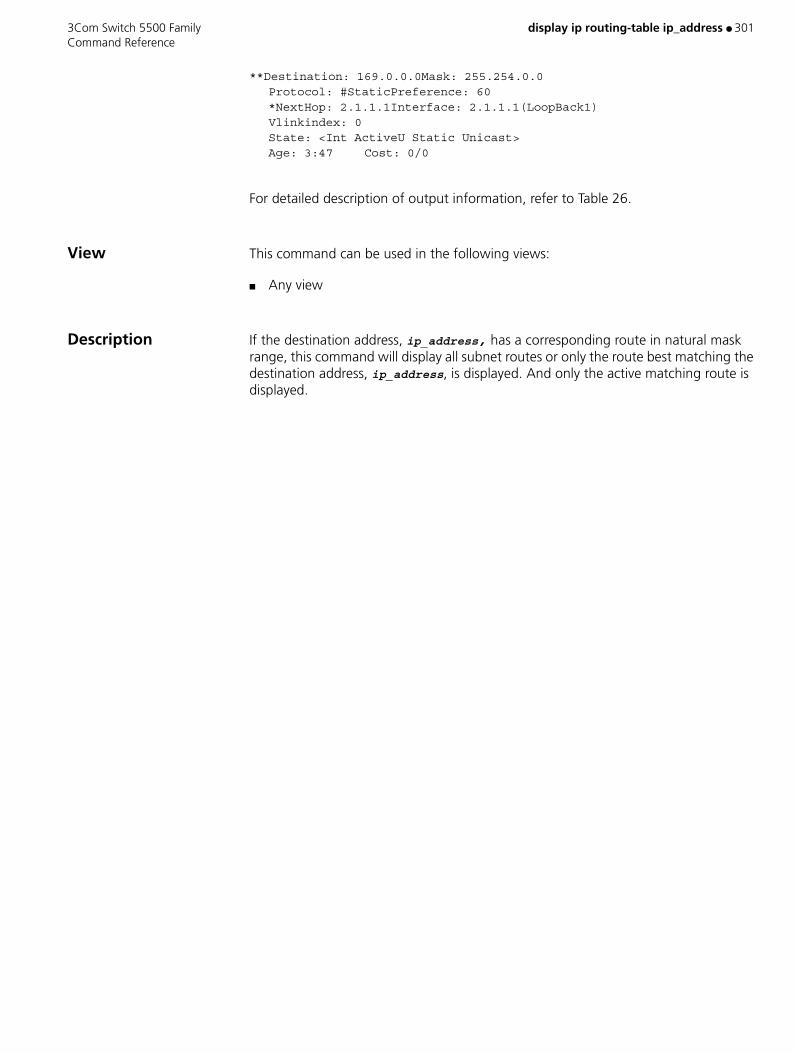
3Com Switch 5500 Family display ip routing-table ip_address ● 301 Command Reference
**Destination: 169.0.0.0Mask: 255.254.0.0Protocol: #StaticPreference: 60*NextHop: 2.1.1.1Interface: 2.1.1.1(LoopBack1)Vlinkindex: 0State: <Int ActiveU Static Unicast>Age: 3:47 Cost: 0/0
For detailed description of output information, refer to Table 26.
View This command can be used in the following views:
■ Any view
Description If the destination address, ip_address, has a corresponding route in natural mask range, this command will display all subnet routes or only the route best matching the destination address, ip_address, is displayed. And only the active matching route is displayed.
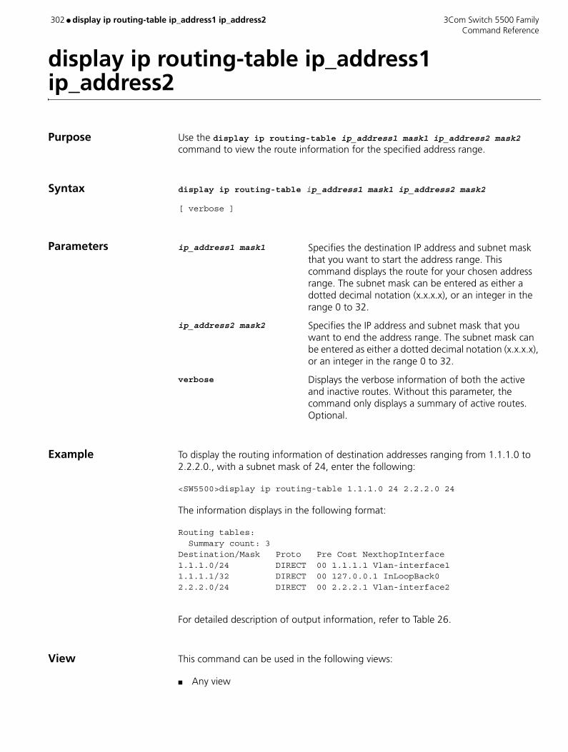
302 ● display ip routing-table ip_address1 ip_address2 3Com Switch 5500 Family Command Reference
display ip routing-table ip_address1 ip_address2
Purpose Use the display ip routing-table ip_address1 mask1 ip_address2 mask2 command to view the route information for the specified address range.
Syntax display ip routing-table ip_address1 mask1 ip_address2 mask2
[ verbose ]
Parameters ip_address1 mask1 Specifies the destination IP address and subnet mask that you want to start the address range. This command displays the route for your chosen address range. The subnet mask can be entered as either a dotted decimal notation (x.x.x.x), or an integer in the range 0 to 32.
ip_address2 mask2 Specifies the IP address and subnet mask that you want to end the address range. The subnet mask can be entered as either a dotted decimal notation (x.x.x.x), or an integer in the range 0 to 32.
verbose Displays the verbose information of both the active and inactive routes. Without this parameter, the command only displays a summary of active routes. Optional.
Example To display the routing information of destination addresses ranging from 1.1.1.0 to 2.2.2.0., with a subnet mask of 24, enter the following:
<SW5500>display ip routing-table 1.1.1.0 24 2.2.2.0 24
The information displays in the following format:
Routing tables: Summary count: 3Destination/Mask Proto Pre Cost NexthopInterface1.1.1.0/24 DIRECT 00 1.1.1.1 Vlan-interface11.1.1.1/32 DIRECT 00 127.0.0.1 InLoopBack02.2.2.0/24 DIRECT 00 2.2.2.1 Vlan-interface2
For detailed description of output information, refer to Table 26.
View This command can be used in the following views:
■ Any view

3Com Switch 5500 Family display ip routing-table ip-prefix ● 303 Command Reference
display ip routing-table ip-prefix
Purpose Use the command display ip routing-table ip-prefix command to display route information.
Use the command display ip routing-table ip-prefix ip_prefix_name to display information on the routes that passed filtering rules for the specified IP prefix name.
Use the command display ip routing-table ip-prefix ip_prefix_name verbose to display both the active and inactive routes that passed filtering rules.
Syntax display ip routing-table ip-prefix ip_prefix_name [ verbose ]
Parameters ip_prefix_name Specifies the ip prefix list name.
verbose Displays verbose information about both the active and inactive routes that passed filtering rules. Without this parameter, this command displays the summary of active routes that passed filtering rules.
Example To display the summary information for ip prefix list abc2, active route only, enter the following:
<SW5500>system-viewSystem View: return to User View with Ctrl+Z.[SW5500]ip ip-prefix abc2 permit 10.1.1.0 24 less-equal 32[SW5500]display ip routing-table ip-prefix abc2
The information displays in the following format:
Routes matched by ip-prefix abc2:Summary count: 2Destination/MaskProtocol PreCost NexthopInterface10.1.1.0/24 DIRECT 0010.1.1.2Vlan-interface110.1.1.2/32 DIRECT 00127.0.0.1InLoopBack0
To display the information on the active and inactive routes for prefix list abc2, enter the following:
[SW5500]display ip routing-table ip-prefix abc2 verbose
The information displays in the following format:
Routes matched by ip-prefix abc2:+ = Active Route, - = Last Active, # = Both* = Next hop in use
Summary count:2**Destination: 10.1.1.0Mask: 255.255.255.0
Protocol: #DIRECTPreference: 0*NextHop: 10.1.1.2Interface: 10.1.1.2(Vlan-interface1)Vlinkindex: 0State: <Int ActiveU Retain Unicast>Age: 3:23:44 Cost: 0/0Tag:0

304 ● display ip routing-table ip-prefix 3Com Switch 5500 Family Command Reference
**Destination: 10.1.1.2Mask: 255. 255. 255. 255Protocol: #DIRECTPreference: 0*NextHop: 127.0.0.1Interface: 127.0.0.1(InLoopBack0)Vlinkindex: 0
State: <NoAdvise Int ActiveU Retain Gateway Unicast>Age: 3:23:44 Cost: 0/0Tag: 0
For detailed description of output information, refer to Table 27.
View This command can be used in the following views:
■ Any view
Description Without the verbose parameter, this command displays the summary of the active routes that passed filtering rules.
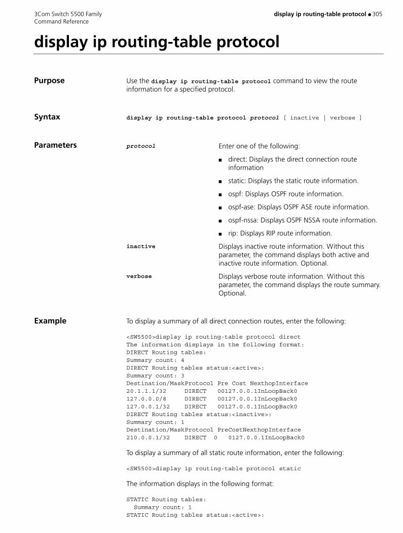
3Com Switch 5500 Family display ip routing-table protocol ● 305 Command Reference
display ip routing-table protocol
Purpose Use the display ip routing-table protocol command to view the route information for a specified protocol.
Syntax display ip routing-table protocol protocol [ inactive | verbose ]
Parameters protocol Enter one of the following:
■ direct: Displays the direct connection route information
■ static: Displays the static route information.
■ ospf: Displays OSPF route information.
■ ospf-ase: Displays OSPF ASE route information.
■ ospf-nssa: Displays OSPF NSSA route information.
■ rip: Displays RIP route information.
inactive Displays inactive route information. Without this parameter, the command displays both active and inactive route information. Optional.
verbose Displays verbose route information. Without this parameter, the command displays the route summary. Optional.
Example To display a summary of all direct connection routes, enter the following:
<SW5500>display ip routing-table protocol directThe information displays in the following format:DIRECT Routing tables:Summary count: 4DIRECT Routing tables status:<active>:Summary count: 3Destination/MaskProtocol Pre Cost NexthopInterface20.1.1.1/32 DIRECT 00127.0.0.1InLoopBack0127.0.0.0/8 DIRECT 00127.0.0.1InLoopBack0127.0.0.1/32 DIRECT 00127.0.0.1InLoopBack0DIRECT Routing tables status:<inactive>:Summary count: 1Destination/MaskProtocol PreCostNexthopInterface210.0.0.1/32 DIRECT 0 0127.0.0.1InLoopBack0
To display a summary of all static route information, enter the following:
<SW5500>display ip routing-table protocol static
The information displays in the following format:
STATIC Routing tables: Summary count: 1STATIC Routing tables status:<active>:
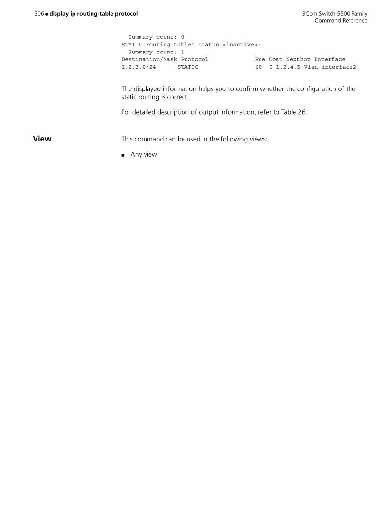
306 ● display ip routing-table protocol 3Com Switch 5500 Family Command Reference
Summary count: 0STATIC Routing tables status:<inactive>: Summary count: 1Destination/Mask Protocol Pre Cost Nexthop Interface1.2.3.0/24 STATIC 60 0 1.2.4.5 Vlan-interface2
The displayed information helps you to confirm whether the configuration of the static routing is correct.
For detailed description of output information, refer to Table 26.
View This command can be used in the following views:
■ Any view
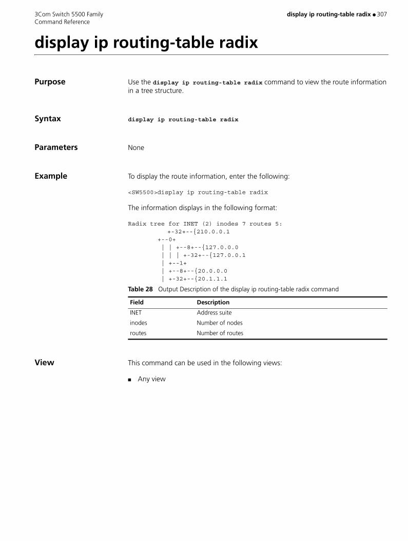
3Com Switch 5500 Family display ip routing-table radix ● 307 Command Reference
display ip routing-table radix
Purpose Use the display ip routing-table radix command to view the route information in a tree structure.
Syntax display ip routing-table radix
Parameters None
Example To display the route information, enter the following:
<SW5500>display ip routing-table radix
The information displays in the following format:
Radix tree for INET (2) inodes 7 routes 5:+-32+--{210.0.0.1
+--0+ | | +--8+--{127.0.0.0 | | | +-32+--{127.0.0.1 | +--1+ | +--8+--{20.0.0.0 | +-32+--{20.1.1.1
View This command can be used in the following views:
■ Any view
Table 28 Output Description of the display ip routing-table radix command
Field Description
INET Address suite
inodes Number of nodes
routes Number of routes
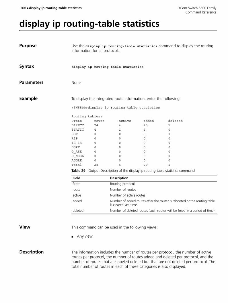
308 ● display ip routing-table statistics 3Com Switch 5500 Family Command Reference
display ip routing-table statistics
Purpose Use the display ip routing-table statistics command to display the routing information for all protocols.
Syntax display ip routing-table statistics
Parameters None
Example To display the integrated route information, enter the following:
<SW5500>display ip routing-table statistics
Routing tables:Proto route active added deletedDIRECT 24 4 25 1STATIC 4 1 4 0BGP 0 0 0 0RIP 0 0 0 0IS-IS 0 0 0 0OSPF 0 0 0 0O_ASE 0 0 0 0O_NSSA 0 0 0 0AGGRE 0 0 0 0Total 28 5 29 1
View This command can be used in the following views:
■ Any view
Description The information includes the number of routes per protocol, the number of active routes per protocol, the number of routes added and deleted per protocol, and the number of routes that are labeled deleted but that are not deleted per protocol. The total number of routes in each of these categories is also displayed.
Table 29 Output Description of the display ip routing-table statistics command
Field Description
Proto Routing protocol
route Number of routes
active Number of active routes
added Number of added routes after the router is rebooted or the routing table is cleared last time.
deleted Number of deleted routes (such routes will be freed in a period of time)
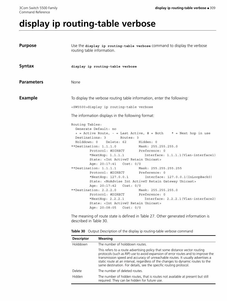
3Com Switch 5500 Family display ip routing-table verbose ● 309 Command Reference
display ip routing-table verbose
Purpose Use the display ip routing-table verbose command to display the verbose routing table information.
Syntax display ip routing-table verbose
Parameters None
Example To display the verbose routing table information, enter the following:
<SW5500>display ip routing-table verbose
The information displays in the following format:
Routing Tables: Generate Default: no + = Active Route, - = Last Active, # = Both * = Next hop in use Destinations: 3 Routes: 3 Holddown: 0 Delete: 62 Hidden: 0**Destination: 1.1.1.0 Mask: 255.255.255.0 Protocol: #DIRECT Preference: 0 *NextHop: 1.1.1.1 Interface: 1.1.1.1(Vlan-interface1) State: <Int ActiveU Retain Unicast> Age: 20:17:41 Cost: 0/0**Destination: 1.1.1.1 Mask: 255.255.255.255 Protocol: #DIRECT Preference: 0 *NextHop: 127.0.0.1 Interface: 127.0.0.1(InLoopBack0) State: <NoAdvise Int ActiveU Retain Gateway Unicast> Age: 20:17:42 Cost: 0/0**Destination: 2.2.2.0 Mask: 255.255.255.0 Protocol: #DIRECT Preference: 0 *NextHop: 2.2.2.1 Interface: 2.2.2.1(Vlan-interface2) State: <Int ActiveU Retain Unicast> Age: 20:08:05 Cost: 0/0
The meaning of route state is defined in Table 27. Other generated information is described in Table 30.
Table 30 Output Description of the display ip routing-table verbose command
Descriptor Meaning
Holddown The number of holddown routes.
This refers to a route advertising policy that some distance vector routing protocols (such as RIP) use to avoid expansion of error routes and to improve the transmission speed and accuracy of unreachable routes. It usually advertises a static route at an interval, regardless of the changes to dynamic routes to the same destination. For details, see the specific routing protocol.
Delete The number of deleted routes.
Hidden The number of hidden routes, that is routes not available at present but still required. They can be hidden for future use.

310 ● display ip routing-table verbose 3Com Switch 5500 Family Command Reference
View This command can be used in the following views:
■ Any view
Description The information displayed includes the route state, the verbose description of each route and the statistics of the entire routing table.
All current routes, including inactive routes and invalid routes, are displayed.
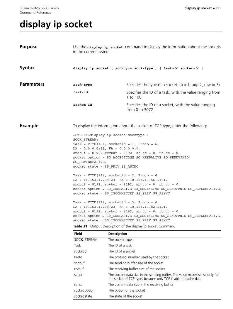
3Com Switch 5500 Family display ip socket ● 311 Command Reference
display ip socket
Purpose Use the display ip socket command to display the information about the sockets in the current system.
Syntax display ip socket [ socktype sock-type ] [ task-id socket-id ]
Parameters sock-type Specifies the type of a socket: (tcp:1, udp 2, raw ip 3).
task-id Specifies the ID of a task, with the value ranging from 1 to 100.
socket-id Specifies the ID of a socket, with the value ranging from 0 to 3072.
Example To display the information about the socket of TCP type, enter the following:
<SW5500>display ip socket socktype 1SOCK_STREAM:Task = VTYD(18), socketid = 1, Proto = 6,LA = 0.0.0.0:23, FA = 0.0.0.0:0,sndbuf = 8192, rcvbuf = 8192, sb_cc = 0, rb_cc = 0,socket option = SO_ACCEPTCONN SO_KEEPALIVE SO_SENDVPNID SO_SETKEEPALIVE,socket state = SS_PRIV SS_ASYNC
Task = VTYD(18), socketid = 2, Proto = 6,LA = 10.153.17.99:23, FA = 10.153.17.56:1161,sndbuf = 8192, rcvbuf = 8192, sb_cc = 0, rb_cc = 0,socket option = SO_KEEPALIVE SO_OOBINLINE SO_SENDVPNID SO_SETKEEPALIVE,socket state = SS_ISCONNECTED SS_PRIV SS_ASYNC
Task = VTYD(18), socketid = 3, Proto = 6,LA = 10.153.17.99:23, FA = 10.153.17.82:1121,sndbuf = 8192, rcvbuf = 8192, sb_cc = 0, rb_cc = 0,socket option = SO_KEEPALIVE SO_OOBINLINE SO_SENDVPNID SO_SETKEEPALIVE,socket state = SS_ISCONNECTED SS_PRIV SS_ASYNC
Table 31 Output Description of the display ip socket Command
Field Description
SOCK_STREAM The socket type
Task The ID of a task
socketid The ID of a socket
Proto The protocol number used by the socket
sndbuf The sending buffer size of the socket
rcvbuf The receiving buffer size of the socket
sb_cc The current data size in the sending buffer. The value makes sense only for the socket of TCP type, because only TCP is able to cache data
rb_cc The current data size in the receiving buffer
socket option The option of the socket
socket state The state of the socket

312 ● display ip socket 3Com Switch 5500 Family Command Reference
View This command can be used in the following views:
■ Any view
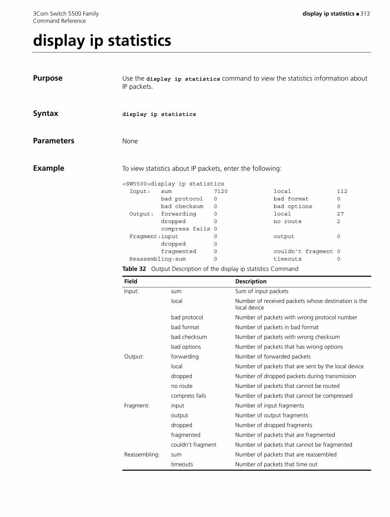
3Com Switch 5500 Family display ip statistics ● 313 Command Reference
display ip statistics
Purpose Use the display ip statistics command to view the statistics information about IP packets.
Syntax display ip statistics
Parameters None
Example To view statistics about IP packets, enter the following:
<SW5500>display ip statistics Input: sum 7120 local 112 bad protocol 0 bad format 0 bad checksum 0 bad options 0 Output: forwarding 0 local 27 dropped 0 no route 2 compress fails 0 Fragment:input 0 output 0 dropped 0 fragmented 0 couldn’t fragment 0 Reassembling:sum 0 timeouts 0
Table 32 Output Description of the display ip statistics Command
Field Description
Input: sum Sum of input packets
local Number of received packets whose destination is the local device
bad protocol Number of packets with wrong protocol number
bad format Number of packets in bad format
bad checksum Number of packets with wrong checksum
bad options Number of packets that has wrong options
Output: forwarding Number of forwarded packets
local Number of packets that are sent by the local device
dropped Number of dropped packets during transmission
no route Number of packets that cannot be routed
compress fails Number of packets that cannot be compressed
Fragment: input Number of input fragments
output Number of output fragments
dropped Number of dropped fragments
fragmented Number of packets that are fragmented
couldn’t fragment Number of packets that cannot be fragmented
Reassembling: sum Number of packets that are reassembled
timeouts Number of packets that time out

314 ● display ip statistics 3Com Switch 5500 Family Command Reference
View This command can be used in the following views:
■ Any view
Related Commands ■ display ip interface vlan-interface
■ reset ip statistics

3Com Switch 5500 Family display isolate port ● 315 Command Reference
display isolate port
Purpose Use the display isolate port command to view port isolation information.
Syntax display isolate port
Parameters None
Example To display port isolation information, enter the following:
<SW5500>display isolate portUNIT 1:Ethernet1/0/1
View This command can be used in the following views:
■ Any view
316 ● display lacp system-id 3Com Switch 5500 Family Command Reference
display lacp system-id
Purpose Use the display lacp system-id command to view actor system ID, including system priority and system MAC address.
Syntax display lacp system-id
Parameters None
Example To display the local system ID.
<SW5500>display lacp system-idActor System ID: 0x8000, 00e0-fc00-0100
View This command can be used in the following views:
■ Any view
Related Commands ■ link-aggregation group agg-id description
■ link-aggregation group agg-id mode

3Com Switch 5500 Family display link-aggregation interface ● 317 Command Reference
display link-aggregation interface
Purpose Use the display link-aggregation interface command to view detailed link aggregation information at a designated port, including aggregation group ID for the port, port priority, operation key, LACP state flag, partner information (system ID, port number, port priority, operation key, LACP state flag, LACP packet statistics).
Syntax display link-aggregation interface { interface_type interface_number | interface_name } [ to { interface_type interface-num | interface_name } ]
Parameters interface { interface_type interface_ num | interface_name } [ to { interface_type interface_ num | interface_name } ] Specifies ports. You can specify multiple sequential
ports with the to parameter, instead of specifying only one port.
interface_name Specifies port name, in the format of interface_name = interface_type interface_num.
interface_type Specifies port type and interface_num port number.
For more information, see the parameter item for the interface command.
Example To display detailed link aggregation information of a link aggregation member port, enter the following:
<SW5500>display link-aggregation interface ethernet4/0/1
If the aggregation has been created manually, the display will be similar to the following:
Ethernet4/0/1: Attached AggID: 1 Local: Port-Priority: 32768, Oper key: 1, Flag: 0x00 Remote: System ID: 0x0, 0000-0000-0000 Port Number: 0, Port-Priority: 0, Oper-key: 0, Flag: 0x00
If the aggregation is static or dynamic, the display will be similar to the following:
<SW5500>display link-aggregation interface ethernet4/0/1Ethernet4/0/1: Attached AggID: 20 Local: Port-Priority: 32768, Oper key: 2, Flag: 0x3d Remote: System ID: 0x8000, 000e-84a6-fb00 Port Number: 2, Port-Priority: 32768 , Oper-key: 10, Flag: 0x3d

318 ● display link-aggregation interface 3Com Switch 5500 Family Command Reference
Received LACP Packets: 8 packet(s), Illegal: 0 packet(s) Sent LACP Packets: 9 packet(s)
View This command can be used in the following views:
■ Any view
Description Note:
Unlike a dynamic aggregation, a manual aggregation has no protocol to get the remote peer information of the partner. Therefore, every item for the remote peer is 0. This does not indicate the actual state of the remote peer.
Related Command display link-aggregation verbose

3Com Switch 5500 Family display link-aggregation summary ● 319 Command Reference
display link-aggregation summary
Purpose Use the display link-aggregation summary command to view summary information of all aggregation groups, including actor system ID, aggregation group ID, aggregate group type, partner system ID, number of selected ports, number of standby ports, load sharing type and master port number.
Syntax display link-aggregation summary
Parameters None
Example To display summary information of all aggregation information, enter the following:
<SW5500>display link-aggregation summaryAggregation Group Type: D -- Dynamic, S -- Static, M -- ManualLoadsharing Type: Shar – Loadsharing, NonS – Non-LoadsharingActor ID: 0x8000, 00e0-fcff-ff04
AL AL Partner ID SelectStandbyShareMasterID Type PortsPortsTypePort-------------------------------------------------------------------1 D 0x8000,00e0-fcff-ff01 10NonSEthernet4/0/110 M none 10NonSEthernet4/0/220 S 0x8000,00e0-fcff-ff01 10NonSEthernet4/0/3
View This command can be used in the following views:
■ Any view

320 ● display link-aggregation verbose 3Com Switch 5500 Family Command Reference
display link-aggregation verbose
Purpose Use the display link-aggregation verbose command to view detailed information of a link aggregation, including aggregation ID, the type of aggregation, load-sharing type, detailed local information (member ports, port status, port priority, LACP state flag and operation key), and detailed remote information (indexes of remote ports, port priority, LACP state flag, operation key and system ID.)
Syntax display link-aggregation verbose [ agg_id ]
Parameters agg_id Aggregation group ID, which must be a valid existing ID. Valid values are 1 to 416.
Example To display detailed information of aggregation group 1, enter the following:
<SW5500>display link-aggregation verbose 1 Loadsharing Type: Shar -- Loadsharing, NonS -- Non-Loadsharing
Aggregation ID: 1, AggregationType: Manual, Loadsharing Type: NonS Aggregation Description: System ID: 0x8000, 000f-cbb7-2e00Port Status: S -- Selected, U -- UnselectedLocal: Port Status Priority Flag Oper-Key-------------------------------------------------------------------- Ethernet1/0/2 U 32768 0x00 1 Ethernet1/0/3 U 32768 0x00 1 Ethernet1/0/4 S 32768 0x00 1
Remote: Actor Partner Priority Flag Oper-Key SystemID-------------------------------------------------------------------- Ethernet1/0/2 0 0 0x00 0 0x0,0000-0000-0000 Ethernet1/0/3 0 0 0x000 0x0,0000-0000-0000 Ethernet1/0/4 0 0 0x00 0 0x0,0000-0000-0000<SW5500>
View This command can be used in the following views:
■ Any view
Description Note: Unlike a dynamic aggregation, a manual aggregation has no protocol to get the remote peer information of the partner. Therefore, every item for the remote peer is 0. This does not indicate the actual state of the remote peer.

3Com Switch 5500 Family display local-server statistics ● 321 Command Reference
display local-server statistics
Purpose Use the display local-server statistics command to view the statistics of local RADIUS authentication server.
Syntax display local-server statistics
Parameters None
Example To display the statistics of local RADIUS authentication server, enter the following
<SW5500>display local-server statisticsThe localserver packet statistics:Receive: 0 Send: 0Discard: 0 Receive Packet Error: 0Auth Reveive: 0 Auth Send: 0Acct Receive: 0 Acct Send: 0
View This command can be used in the following views:
■ Any view
Related Command local-server
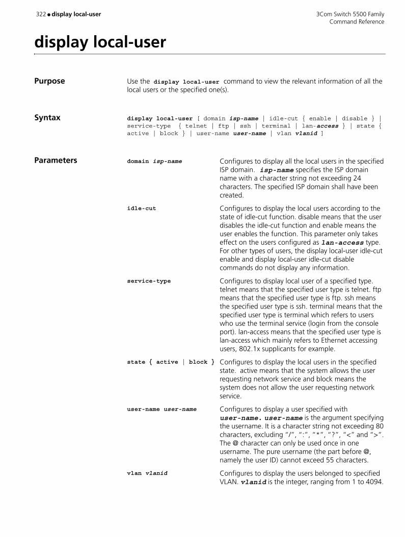
322 ● display local-user 3Com Switch 5500 Family Command Reference
display local-user
Purpose Use the display local-user command to view the relevant information of all the local users or the specified one(s).
Syntax display local-user [ domain isp-name | idle-cut { enable | disable } | service-type { telnet | ftp | ssh | terminal | lan-access } | state { active | block } | user-name user-name | vlan vlanid ]
Parameters domain isp-name Configures to display all the local users in the specified ISP domain. isp-name specifies the ISP domain name with a character string not exceeding 24 characters. The specified ISP domain shall have been created.
idle-cut Configures to display the local users according to the state of idle-cut function. disable means that the user disables the idle-cut function and enable means the user enables the function. This parameter only takes effect on the users configured as lan-access type. For other types of users, the display local-user idle-cut enable and display local-user idle-cut disable commands do not display any information.
service-type Configures to display local user of a specified type. telnet means that the specified user type is telnet. ftp means that the specified user type is ftp. ssh means the specified user type is ssh. terminal means that the specified user type is terminal which refers to users who use the terminal service (login from the console port). lan-access means that the specified user type is lan-access which mainly refers to Ethernet accessing users, 802.1x supplicants for example.
state { active | block } Configures to display the local users in the specified state. active means that the system allows the user requesting network service and block means the system does not allow the user requesting network service.
user-name user-name Configures to display a user specified with user-name. user-name is the argument specifying the username. It is a character string not exceeding 80 characters, excluding “/”, “:”, “*”, “?”, “<” and “>”. The @ character can only be used once in one username. The pure username (the part before @, namely the user ID) cannot exceed 55 characters.
vlan vlanid Configures to display the users belonged to specified VLAN. vlanid is the integer, ranging from 1 to 4094.

3Com Switch 5500 Family display local-user ● 323 Command Reference
Example To display the relevant information of all the local users, enter the following:
<SW5500>display local-userThe contents of local user xxx: State: Active ServiceType Mask: Idle Cut: Disable AccessLimit: Disable Current AccessNum: 0 Bind location: Disable Vlan ID: DisableTotal 1 local user(s) Matched,1 listed.
View This command can be used in the following views:
■ Any view
Description This command displays the relevant information about a specified or all the local users. The output can help you with the fault diagnosis and troubleshooting related to local user.
Related Command local-user

324 ● display logbuffer 3Com Switch 5500 Family Command Reference
display logbuffer
Purpose Use the display logbuffer command to display the status of the log buffer and the records in the log buffer.
Syntax display logbuffer [ unit unit-id ] [ level severity | size buffersize ]* [ | { begin | exclude | include } regular-expression ]
Parameters unit-id Unit ID.
level Specifies an information severity level.
severity Information severity, ranging from 1 to 8.
size Specifies the size of the memory buffer you want to display.
buffersize Size of the memory buffer, represented by the number of messages it holds. It ranges from 1 to 1024 and defaults to 256.
| Filters output configuration information with a regular expression.
begin Displays configurations with the specified starting characters.
exclude Displays configurations excluding the specified characters.
include Displays configurations including the specified characters.
regular-expression Regular expression.
Example Display the status of the log buffer and the records in the log buffer.
<S5500> display logbufferLogging buffer configuration and contents:enabledAllowed max buffer size : 1024
Table 33 Severity definitions made on the information center
Severity Value Description
emergencies 1 Emergent errors
alerts 2 Errors that need to be corrected immediately
critical 3 Critical errors
errors 4 Errors that need to be considered but are not critical
warnings 5 Warnings that prompt possible errors
notifications 6 Information that needs to be noticed
informational 7 Normal prompting information
debugging 8 Debug information

3Com Switch 5500 Family display logbuffer ● 325 Command Reference
Actual buffer size : 512Channel number : 4 , Channel name : logbufferDropped messages : 0Overwritten messages : 0Current messages : 91
View This command can be used in the following views:
■ Any view

326 ● display loopback-detection 3Com Switch 5500 Family Command Reference
display loopback-detection
Purpose Use the display loopback-detection command to display whether loopback detection function is enabled or not.
Syntax display loopback-detection
Parameters None
Example Display whether loopback detection function is enabled or not.
<S5500> display loopback-detectionPort Ethernet1/0/1 loopback-detection is runningSystem Loopback-detection is runningDetection interval time is 30 secondsThere is no port existing loopback link
View This command can be used in the following views:
■ Any view
Description If loopback is enabled, then the time interval for the loopback detection function as well as information on the port will be displayed.
Table 34 Explain fields involved in loopback detection function
Fields Explanation
Port GigabitEthernet1/0/1 loopback-detection is running.
Loopback detection function for GigabitEthernet1/0/1 is enabled.
System Loopback-detection is running. System loopback detection function is enabled.
Detection interval time is 30 seconds. Detection time interval is set to be 30 seconds.
There is no port existing loopback link. Currently no port is detected with loopback.

3Com Switch 5500 Family display mac-address ● 327 Command Reference
display mac-address
Purpose Use the display mac-address command to display MAC address table information.
Syntax display mac-address [ mac-addr [ vlan vlan-id ] | [ static | dynamic | blackhole ] [ interface { interface-name | interface-type interface-num } ] [ vlan vlan-id ] [ count ] ]
Parameters mac-addr Specifies the MAC address.
vlan-id Specifies the VLAN ID.
static Static table entry, lost after resetting switch.
dynamic Dynamic table entry, which will be aged.
blackhole Blackhole table entry, the packet with this destination MAC address will be discarded.
interface-type Specifies the interface type.
interface-num Specifies the interface number.�
interface-name Specifies the interface name.
For details about the interface-type, interface-num and interface-name parameters, refer to the Port Configuration in this manual.
count the display information will only contain the number of MAC addresses in the MAC address table if the user enters this parameter when using this command.
Example Show the information of the entry with MAC address at 00e0-fc01-0101
<SW5500>sysSystem View: return to User View with Ctrl+Z.[SW5500]display mac-address 00e0-fc01-0101MAC ADDR VLAN ID STATEPORT INDEX AGING TIME(s)00e0-fc01-0101 1 LearnedEthernet1/0/1300
View This command can be used in the following views:
■ Any view
Description When managing the Layer-2 addresses of the switch, the administrator can perform this command to view such information as the Layer-2 address table, address status (static or dynamic), Ethernet port of the MAC address, VLAN of the address, and system address aging time.

328 ● display mac-address 3Com Switch 5500 Family Command Reference
Related Commands ■ mac-address
■ mac-address timer

3Com Switch 5500 Family display mac-address aging-time ● 329 Command Reference
display mac-address aging-time
Purpose Use the display mac-address aging-time command to display the aging time of the dynamic entry in the MAC address table.
Syntax display mac-address aging-time
Parameters None
Example Display the aging time of the dynamic entry in the MAC address table.
<SW5500>sysSystem View: return to User View with Ctrl+Z.[SW5500]display mac-address aging-timemac-address aging-time: 300s
The above information indicates that the aging time of the dynamic entry in the MAC address is 300s.
<SW5500>sysSystem View: return to User View with Ctrl+Z.[sw5500] display mac-address aging-timemac-address aging-time: no-aging
The above information indicates that the dynamic entry in the MAC address table is no-aging.
View This command can be used in the following views:
■ Any view
Related Commands ■ display mac-address
■ mac-address
■ mac-address timer

330 ● display mac-address multicast static 3Com Switch 5500 Family Command Reference
display mac-address multicast static
Purpose Use the display mac-address multicast static command to display the multicast MAC address entries manually configured on the switch, with each entry containing the following information: multicast MAC address, VLAN ID, MAC address state, port number(s), and aging time of each port.
Syntax display mac-address multicast static [ count | mac-address vlan vlan-id | vlan vlan-id ]
Parameters mac-address vlan vlan-id Multicast MAC address entry in a specified VLAN.
count Displays the number of the MAC address entries.
vlan-id VLAN ID.
Example Display all the multicast MAC address entries manually configured in VLAN 1.
<S5500>display mac-address multicast static vlan 1MAC ADDRVLAN IDSTATEPORT INDEXAGING TIME(s)0100-0001-00011Config staticEthernet1/0/1 N/A Ethernet1/0/2 Ethernet1/0/3 Ethernet1/0/4--- 1 static mac address(es) found ---
View This command can be used in the following views:
■ Any view
Description ■ Executing this command with neither mac-address vlan vlan-id nor vlan vlan-id will display all the multicast MAC address entries added on the switch.
■ Executing this command with vlan vlan-id will display all the multicast MAC address entries added to the specified VLAN.
■ Executing this command with mac-address vlan vlan-id will display the multicast MAC address entry added to the specified VLAN with the specified multicast MAC address.
■ Executing this command with the count keyword will display the number of the configured multicast MAC address entries on the switch.

3Com Switch 5500 Family display mac-authentication ● 331 Command Reference
display mac-authentication
Purpose Use the display mac-authentication command to display the global information about centralized MAC address authentication, including the state of centralized MAC address authentication (enabled or disabled), values of centralized MAC address authentication timers, the number of online users, MAC addresses during quiet period, and MAC authentication information about each port.
Syntax display mac-authentication [ interface interface-list ]
Parameters interface-list Lists of Ethernet ports. You can specify multiple Ethernet ports by providing this argument in the form of interface-list = { interface-type interface-number [ to interface-type interface-number ] } &<1-10>, where &<1-10> means that you can provide up to 10 port indexes/port index lists for this argument.
Example Display the global information about centralized MAC address authentication.
<S5500> display mac-authenticationmac address authentication is Enabled. authentication mode is UsernameAsMacAddress Fixed username:mac Fixed password:not configured offline detect period is 300s quiet period is 1 minute(s). server response timeout value is 100s max allowed user number is 1024 current user number amounts to 0 current domain: not configured, use default domainSilent Mac User info: MAC ADDR From Port Port IndexGigabitEthernet1/0/1 is link-up MAC address authentication is Enabled Authenticate success: 0, failed: 0 Current online user number is 0 MAC ADDR Authenticate state AuthIndex
...omitted
Table 35 Description on the fields of the display mac-authentication command
Field Description
mac address authentication is Enabled
Centralized MAC address authentication is enabled.
authentication mode Centralized MAC address authentication mode. The default is MAC address mode.
the Fixed username User name of fixed mode. The default is mac.
the Fixed password Password of fixed mode. It is not configured by default.
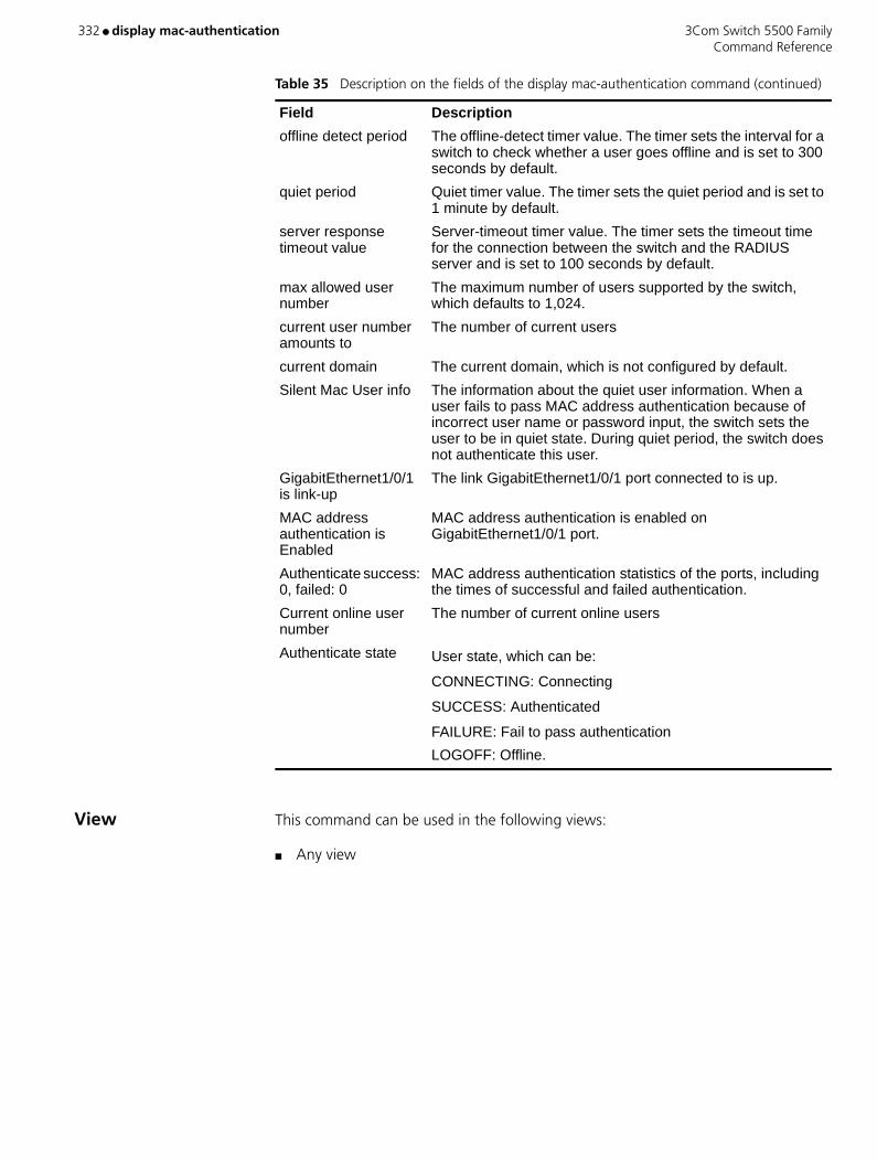
332 ● display mac-authentication 3Com Switch 5500 Family Command Reference
View This command can be used in the following views:
■ Any view
offline detect period The offline-detect timer value. The timer sets the interval for a switch to check whether a user goes offline and is set to 300 seconds by default.
quiet period Quiet timer value. The timer sets the quiet period and is set to 1 minute by default.
server response timeout value
Server-timeout timer value. The timer sets the timeout time for the connection between the switch and the RADIUS server and is set to 100 seconds by default.
max allowed user number
The maximum number of users supported by the switch, which defaults to 1,024.
current user number amounts to
The number of current users
current domain The current domain, which is not configured by default.
Silent Mac User info The information about the quiet user information. When a user fails to pass MAC address authentication because of incorrect user name or password input, the switch sets the user to be in quiet state. During quiet period, the switch does not authenticate this user.
GigabitEthernet1/0/1 is link-up
The link GigabitEthernet1/0/1 port connected to is up.
MAC address authentication is Enabled
MAC address authentication is enabled on GigabitEthernet1/0/1 port.
Authenticate success: 0, failed: 0
MAC address authentication statistics of the ports, including the times of successful and failed authentication.
Current online user number
The number of current online users
Authenticate state User state, which can be:
CONNECTING: Connecting
SUCCESS: Authenticated
FAILURE: Fail to pass authentication
LOGOFF: Offline.
Table 35 Description on the fields of the display mac-authentication command (continued)
Field Description

3Com Switch 5500 Family display memory ● 333 Command Reference
display memory
Purpose Use the display memory command to view the memory setting.
Syntax display memory [ unit unit-id ]
Parameters unit-id Specifies the unit ID.
Example To display the current memory setting, enter the following:
<SW5500> display memoryUnit 1System Available Memory(bytes): 31608192System Used Memory(bytes): 14970948Used Rate: 47%
The displayed information is defined in Table 36.
View This command can be used in the following views:
■ Any view
Table 36 Output Description of the display memory command
Item Description
Unit 1 Display the memory information of unit 1.
System Total Memory(bytes) The total number of the Switch memory in bytes.
Total Used Memory(bytes) The total number of the used Switch memory in bytes.
Used Rate The used rate of the Switch memory.

334 ● display memory 3Com Switch 5500 Family Command Reference
display memory
Purpose Use the display memory command to display the current system memory status.
Syntax display memory [ unit unit-id ]
Parameters unit unit-id Specifies the Unit ID of the switch
Example To display the current memory status, enter the following:
<SW5500>display memory
The information displays in the following format:
Unit 1System Available Memory(bytes): 31608192System Used Memory(bytes): 14723652Used Rate: 46%
Table 37 Display information
View This command can be used in the following views:
■ Any view
Field Description
System Available Memory (bytes) The Total Memory of switch, unit in byte
System Used Memory (bytes) The Total used Memory of switch, unit in byte
Used Rate The memory used rate

3Com Switch 5500 Family display memory limit ● 335 Command Reference
display memory limit
Purpose Use the display memory limit command to display the memory setting and state information related to the Ethernet switch capacity, including available memory and state information about connections, such as times for disconnecting connections, times for reestablishing connections, and the current state of the system.
Syntax display memory limit
Parameters None
Example Display the current memory setting and state information.
<SW5500>display memory limitCurrent memory limit configuration information: system memory safety: 6 (MBytes) system memory limit: 5 (MBytes) auto-establish enabled
Free Memory: 16631660 (Bytes)
The state information about connection: The times of disconnect: 0 The times of reconnect: 0 The current state: Normal
The displayed information is defined in Table 38.
View This command can be used in the following views:
■ Any view
Table 38 Output Description of the display memory limit command
Item Description
system memory safety The safety value of the Switch memory
system memory limit The lower limit of the Switch memory
auto-establish enabled The system allows recovering the connection automatically. (If the automatic recover is disabled, auto-establish disable will be displayed.)
Free Memory: 17781708 (Byte)
The size of the current idle memory is 17781708 bytes, that is, 17,782Mbytes.
The times of disconnect: 0 The times of the connection disconnecting of the Switch is 0.
The times of reconnect: 0 The times of the connection reestablishment of the Switch is 0.
The current state: Normal The current state is normal. If entering the emergent state, the display will read Emergence.

336 ● display mirror 3Com Switch 5500 Family Command Reference
display mirror
Purpose Use the display mirror command to view port mirroring configuration, including monitored ports, monitor port and monitor direction, and so on.
Syntax display mirror
Parameters None
Example To display the port mirroring configuration, enter the following:
<SW5500>system-viewSystem View: return to User View with Ctrl+Z[SW5500] display mirror
View This command can be used in the following views:
■ Any view
Related Commands ■ mirroring-port
■ monitor-port

3Com Switch 5500 Family display mirroring-group ● 337 Command Reference
display mirroring-group
Purpose Use the display mirroring-group command to display the parameter settings of a port mirroring group.
Syntax display mirroring-group { group-id | all | local | remote-destination | remote-source }
Parameters group-id The group number of a port mirroring group. Valid values are 1 to 20.
local Signifies that the specified mirroring group is a local port mirroring group.
remote-destination Signifies that the specified mirroring group is the destination group for remote mirroring.
remote-source Signifies that the specified mirroring group is the source group for remote mirroring.
all All mirroring groups.
Example Display the parameter setting of the mirroring group.
<S5500> display mirroring-group allmirroring-group 1: type: local status: active mirroring port: Ethernet1/0/1 inbound monitor port: Ethernet1/0/2
View This command can be used in the following views:
■ Any view
Description Local mirroring group information includes:
■ Group number
■ Group type: local
■ Group state
■ Information of the monitored port
■ Information of the monitoring port
Information displayed on the destination mirroring group of remote mirroring includes:
■ Group number
■ Group type: remote-destination
338 ● display mirroring-group 3Com Switch 5500 Family Command Reference
■ Group state
■ Information of the destination port
■ Remote-probe vlan information
Information displayed on the source mirroring group of remote mirroring includes:
■ Group number
■ Group type: remote-source
■ Group state
■ Information of the source port
■ Information of the reflector port
■ Remote-probe vlan information
3Com Switch 5500 Family display mpm ● 339 Command Reference
display mpm
Purpose The display mpm command displays information about the multicast port management parameters.
Syntax display mpm [ forwarding table | group ]
Parameters forwarding table Multicast forwarding table information.
group MPM group and MAC information.
View This command can be used in the following views:
■ Any view
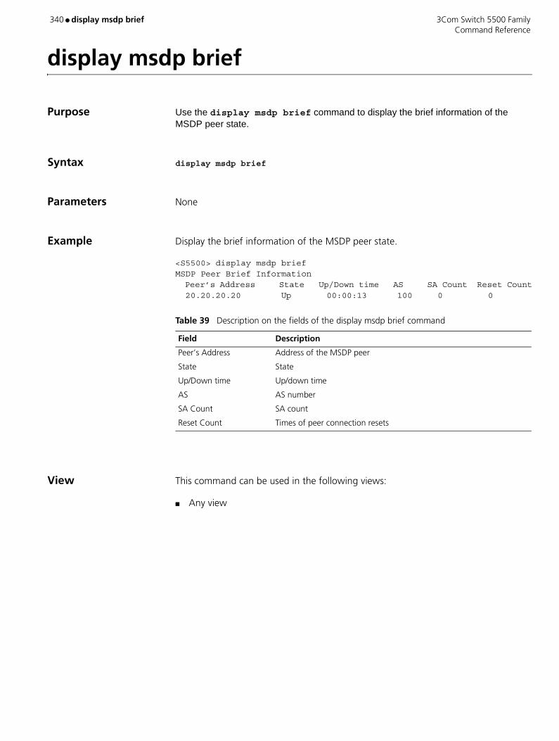
340 ● display msdp brief 3Com Switch 5500 Family Command Reference
display msdp brief
Purpose Use the display msdp brief command to display the brief information of the MSDP peer state.
Syntax display msdp brief
Parameters None
Example Display the brief information of the MSDP peer state.
<S5500> display msdp briefMSDP Peer Brief Information Peer’s Address State Up/Down time AS SA Count Reset Count 20.20.20.20 Up 00:00:13 100 0 0
View This command can be used in the following views:
■ Any view
Table 39 Description on the fields of the display msdp brief command
Field Description
Peer’s Address Address of the MSDP peer
State State
Up/Down time Up/down time
AS AS number
SA Count SA count
Reset Count Times of peer connection resets

3Com Switch 5500 Family display msdp peer-status ● 341 Command Reference
display msdp peer-status
Purpose Use the display msdp peer-status command to display the detailed information of the MSDP peer state.
Syntax display msdp peer-status [ peer-address ]
Parameters peer-address IP address of an MSDP peer, in the dotted decimal format.
Example Display the detailed information of MSDP peer state.
<S5500> display msdp peer-status 10.110.11.11MSDP Peer 20.20.20.20, AS 100 Description: Information about connection status: State: Up Up/down time: 14:41:08 Resets: 0 Connection interface: LoopBack0 (20.20.20.30) Number of sent/received messages: 867/947 Number of discarded output messages: 0 Elapsed time since last connection or counters clear: 14:42:40 Information about (Source, Group)-based SA filtering policy: Import policy: none Export policy: none Information about SA-Requests: Policy to accept SA-Request messages: none Sending SA-Requests status: disable Minimum TTL to forward SA with encapsulated data: 0 SAs learned from this peer: 0, SA-cache maximum for the peer: none Input queue size: 0, Output queue size: 0 Counters for MSDP message: Count of RPF check failure: 0 Incoming/outgoing SA messages: 0/0 Incoming/outgoing SA requests: 0/0 Incoming/outgoing SA responses: 0/0 Incoming/outgoing data packets: 0/0
View This command can be used in the following views:
■ Any view
Related Command peer
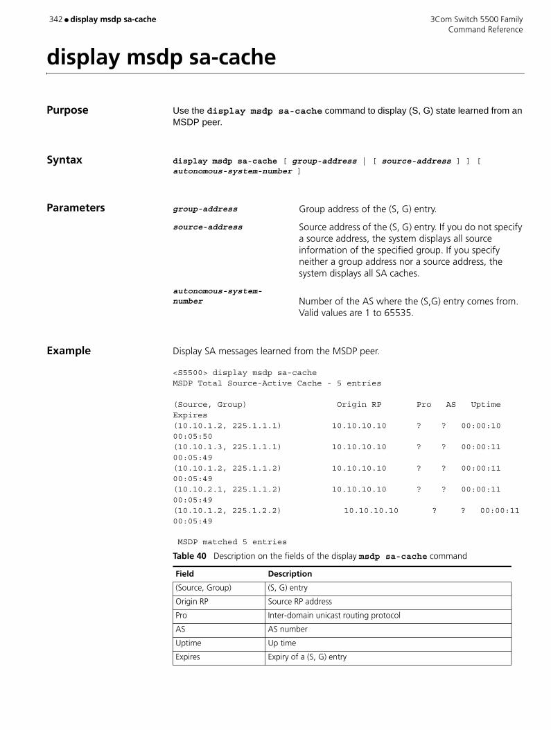
342 ● display msdp sa-cache 3Com Switch 5500 Family Command Reference
display msdp sa-cache
Purpose Use the display msdp sa-cache command to display (S, G) state learned from an MSDP peer.
Syntax display msdp sa-cache [ group-address | [ source-address ] ] [ autonomous-system-number ]
Parameters group-address Group address of the (S, G) entry.
source-address Source address of the (S, G) entry. If you do not specify a source address, the system displays all source information of the specified group. If you specify neither a group address nor a source address, the system displays all SA caches.
autonomous-system- number Number of the AS where the (S,G) entry comes from.
Valid values are 1 to 65535.
Example Display SA messages learned from the MSDP peer.
<S5500> display msdp sa-cacheMSDP Total Source-Active Cache - 5 entries
(Source, Group) Origin RP Pro AS Uptime Expires(10.10.1.2, 225.1.1.1) 10.10.10.10 ? ? 00:00:10 00:05:50(10.10.1.3, 225.1.1.1) 10.10.10.10 ? ? 00:00:11 00:05:49(10.10.1.2, 225.1.1.2) 10.10.10.10 ? ? 00:00:11 00:05:49(10.10.2.1, 225.1.1.2) 10.10.10.10 ? ? 00:00:11 00:05:49(10.10.1.2, 225.1.2.2) 10.10.10.10 ? ? 00:00:11 00:05:49
MSDP matched 5 entries
Table 40 Description on the fields of the display msdp sa-cache command
Field Description
(Source, Group) (S, G) entry
Origin RP Source RP address
Pro Inter-domain unicast routing protocol
AS AS number
Uptime Up time
Expires Expiry of a (S, G) entry

3Com Switch 5500 Family display msdp sa-cache ● 343 Command Reference
View This command can be used in the following views:
■ Any view
Description You must configure the cache-sa-enable command before the system can display the cache state information.

344 ● display msdp sa-count 3Com Switch 5500 Family Command Reference
display msdp sa-count
Purpose Use the display msdp sa-count command to display the number of sources and groups in MSDP cache.
Syntax display msdp sa-count [ autonomous-system-number ]
Parameters autonomous-system- number Specifies the AS where a source and group come from.
Valid values are 1 to 65535.
Example View the number of sources and groups in MSDP cache.
<S5500> display msdp sa-countNumber of cached Source-Active entries, counted by Peer Peer’s Address Number of SA 10.10.10.10 5
Number of source and group, counted by AS AS Number of source Number of group 100 3 3
Total Source-Active entries: 5
View This command can be used in the following views:
■ Any view
Description The debugging output of this command is available only after the configuration of the cache-sa-enable command.
Table 41 Description on the fields of the display msdp sa-count command
Field Description
Peer’s Address Address of an MSDP peer
Number of SA Number of SA messages
AS AS number
Number of source Number of sources
Number of group Number of groups

3Com Switch 5500 Family display multicast forwarding-table ● 345 Command Reference
display multicast forwarding-table
Purpose Use the display multicast forwarding-table to view the information of IP multicast forwarding table.
Syntax display multicast forwarding-table [ group-address [ mask { mask | mask-length } ] | source-address [ mask { mask | mask-length } ] | incoming-interface { interface-type interface-number | register }]*
Parameters group-address Multicast group address, used to specify a multicast group, ranging from 224.0.0.0 to 239.255.255.255.
source-address Unicast IP address of the multicast source.
incoming-interface Incoming interface of the multicast forwarding table.
register Register interface of PIM-SM.
Example View the multicast forwarding table information.
<SW5500>display multicast forwarding-tableMulticast Forwarding Cache TableTotal 2 entries
00001. (4.4.4.4, 224.2.254.84), iif Vlan-interface1, 0 oifs Matched 240 pkts(11288 bytes), Wrong If 0 pkts Forwarded 232 pkts(11288 bytes)
00002. (4.4.4.4, 224.2.149.17), iif Vlan-interface1, 1 oifs List of outgoing interface: 01: Vlan-interface2 Matched 236 pkts(3267 bytes), Wrong If 0 pkts Forwarded 233 pkts(3267 bytes)
Matched 2 entries
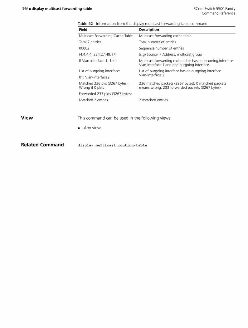
346 ● display multicast forwarding-table 3Com Switch 5500 Family Command Reference
Table 42 Information from the display multicast forwarding-table command
View This command can be used in the following views:
■ Any view
Related Command display multicast routing-table
Field Description
Multicast Forwarding Cache Table Multicast forwarding cache table
Total 2 entries Total number of entries
00002 Sequence number of entries
(4.4.4.4, 224.2.149.17) (s,g) Source IP Address, multicast group
If Vlan-interface 1, 1oifs Multicast forwarding cache table has an incoming interface Vlan-interface 1 and one outgoing interface
List of outgoing interface:
01: Vlan-interface2
List of outgoing interface has an outgoing interface Vlan-interface 2
Matched 236 pks (3267 bytes), Wrong if 0 pkts
Forwarded 233 pkts (3267 bytes)
236 matched packets (3267 bytes); 0 matched packets means wrong; 233 forwarded packets (3267 bytes)
Matched 2 entries 2 matched entries
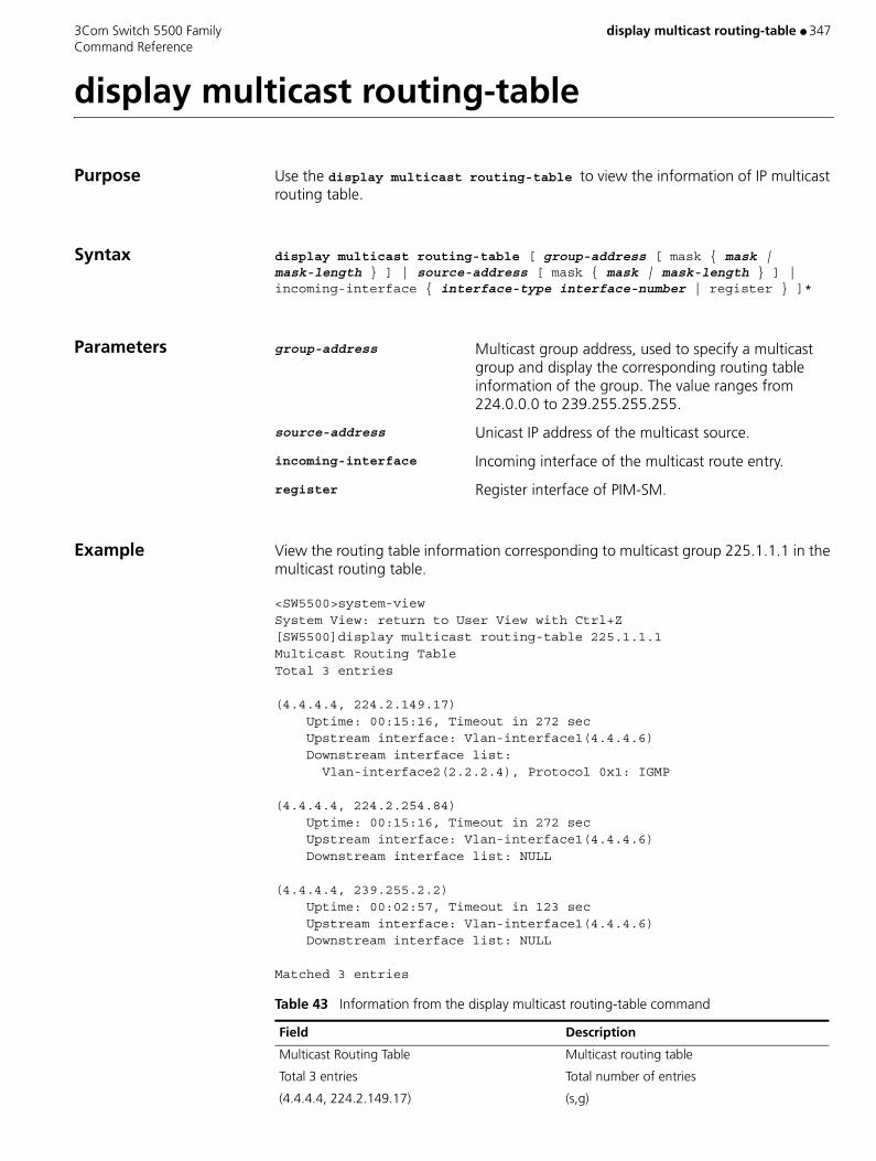
3Com Switch 5500 Family display multicast routing-table ● 347 Command Reference
display multicast routing-table
Purpose Use the display multicast routing-table to view the information of IP multicast routing table.
Syntax display multicast routing-table [ group-address [ mask { mask | mask-length } ] | source-address [ mask { mask | mask-length } ] | incoming-interface { interface-type interface-number | register } ]*
Parameters group-address Multicast group address, used to specify a multicast group and display the corresponding routing table information of the group. The value ranges from 224.0.0.0 to 239.255.255.255.
source-address Unicast IP address of the multicast source.
incoming-interface Incoming interface of the multicast route entry.
register Register interface of PIM-SM.
Example View the routing table information corresponding to multicast group 225.1.1.1 in the multicast routing table.
<SW5500>system-viewSystem View: return to User View with Ctrl+Z[SW5500]display multicast routing-table 225.1.1.1Multicast Routing TableTotal 3 entries
(4.4.4.4, 224.2.149.17) Uptime: 00:15:16, Timeout in 272 sec Upstream interface: Vlan-interface1(4.4.4.6) Downstream interface list: Vlan-interface2(2.2.2.4), Protocol 0x1: IGMP
(4.4.4.4, 224.2.254.84) Uptime: 00:15:16, Timeout in 272 sec Upstream interface: Vlan-interface1(4.4.4.6) Downstream interface list: NULL
(4.4.4.4, 239.255.2.2) Uptime: 00:02:57, Timeout in 123 sec Upstream interface: Vlan-interface1(4.4.4.6) Downstream interface list: NULL
Matched 3 entries
Table 43 Information from the display multicast routing-table command
Field Description
Multicast Routing Table Multicast routing table
Total 3 entries Total number of entries
(4.4.4.4, 224.2.149.17) (s,g)
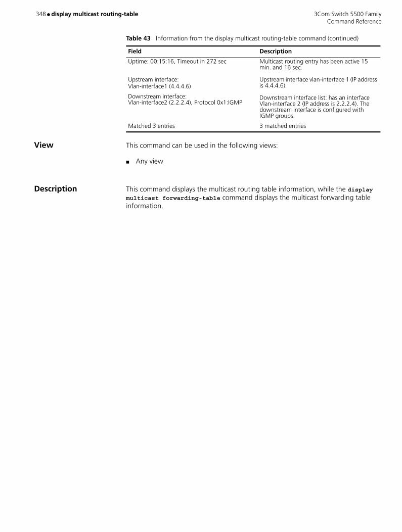
348 ● display multicast routing-table 3Com Switch 5500 Family Command Reference
View This command can be used in the following views:
■ Any view
Description This command displays the multicast routing table information, while the display multicast forwarding-table command displays the multicast forwarding table information.
Uptime: 00:15:16, Timeout in 272 sec
Upstream interface: Vlan-interface1 (4.4.4.6)
Downstream interface: Vlan-interface2 (2.2.2.4), Protocol 0x1:IGMP
Multicast routing entry has been active 15 min. and 16 sec. Upstream interface vlan-interface 1 (IP address is 4.4.4.6). Downstream interface list: has an interface Vlan-interface 2 (IP address is 2.2.2.4). The downstream interface is configured with IGMP groups.
Matched 3 entries 3 matched entries
Table 43 Information from the display multicast routing-table command (continued)
Field Description
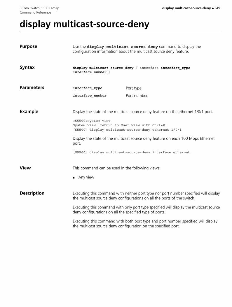
3Com Switch 5500 Family display multicast-source-deny ● 349 Command Reference
display multicast-source-deny
Purpose Use the display multicast-source-deny command to display the configuration information about the multicast source deny feature.
Syntax display multicast-source-deny [ interface interface_type interface_number ]
Parameters interface_type Port type.
interface_number Port number.
Example Display the state of the multicast source deny feature on the ethernet 1/0/1 port.
<S5500>system-viewSystem View: return to User View with Ctrl+Z.[S5500] display multicast-source-deny ethernet 1/0/1
Display the state of the multicast source deny feature on each 100 Mbps Ethernet port.
[S5500] display multicast-source-deny interface ethernet
View This command can be used in the following views:
■ Any view
Description Executing this command with neither port type nor port number specified will display the multicast source deny configurations on all the ports of the switch.
Executing this command with only port type specified will display the multicast source deny configurations on all the specified type of ports.
Executing this command with both port type and port number specified will display the multicast source deny configuration on the specified port.
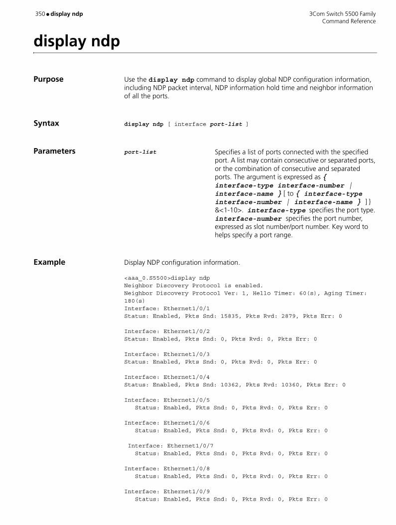
350 ● display ndp 3Com Switch 5500 Family Command Reference
display ndp
Purpose Use the display ndp command to display global NDP configuration information, including NDP packet interval, NDP information hold time and neighbor information of all the ports.
Syntax display ndp [ interface port-list ]
Parameters port-list Specifies a list of ports connected with the specified port. A list may contain consecutive or separated ports, or the combination of consecutive and separated ports. The argument is expressed as { interface-type interface-number | interface-name } [ to { interface-type interface-number | interface-name } ] } &<1-10>. interface-type specifies the port type. interface-number specifies the port number, expressed as slot number/port number. Key word to helps specify a port range.
Example Display NDP configuration information.
<aaa_0.S5500>display ndpNeighbor Discovery Protocol is enabled.Neighbor Discovery Protocol Ver: 1, Hello Timer: 60(s), Aging Timer: 180(s)Interface: Ethernet1/0/1Status: Enabled, Pkts Snd: 15835, Pkts Rvd: 2879, Pkts Err: 0
Interface: Ethernet1/0/2Status: Enabled, Pkts Snd: 0, Pkts Rvd: 0, Pkts Err: 0
Interface: Ethernet1/0/3Status: Enabled, Pkts Snd: 0, Pkts Rvd: 0, Pkts Err: 0
Interface: Ethernet1/0/4Status: Enabled, Pkts Snd: 10362, Pkts Rvd: 10360, Pkts Err: 0
Interface: Ethernet1/0/5 Status: Enabled, Pkts Snd: 0, Pkts Rvd: 0, Pkts Err: 0
Interface: Ethernet1/0/6 Status: Enabled, Pkts Snd: 0, Pkts Rvd: 0, Pkts Err: 0
Interface: Ethernet1/0/7 Status: Enabled, Pkts Snd: 0, Pkts Rvd: 0, Pkts Err: 0
Interface: Ethernet1/0/8 Status: Enabled, Pkts Snd: 0, Pkts Rvd: 0, Pkts Err: 0
Interface: Ethernet1/0/9 Status: Enabled, Pkts Snd: 0, Pkts Rvd: 0, Pkts Err: 0

3Com Switch 5500 Family display ndp ● 351 Command Reference
Interface: Ethernet1/0/10 Status: Enabled, Pkts Snd: 0, Pkts Rvd: 0, Pkts Err: 0
Interface: Ethernet1/0/11 Status: Enabled, Pkts Snd: 0, Pkts Rvd: 0, Pkts Err: 0
Interface: Ethernet1/0/12 Status: Enabled, Pkts Snd: 0, Pkts Rvd: 0, Pkts Err: 0
Interface: Ethernet1/0/13 Status: Enabled, Pkts Snd: 0, Pkts Rvd: 0, Pkts Err: 0
Interface: Ethernet1/0/14 Status: Enabled, Pkts Snd: 0, Pkts Rvd: 0, Pkts Err: 0
Display NDP configuration information.
<aaa_0.S5500> display ndp interface Ethernet 1/0/1Interface: Ethernet1/0/1 Status: Enabled, Pkts Snd: 15835, Pkts Rvd: 2879, Pkts Err: 0 Neighbor 1: Aging Time: 147(s) MAC Address : 00e0-fc00-5500 Port Name : Ethernet1/0/1 Software Ver: V100R002B01D001 Device Name : S5500 S3928 Port Duplex : AUTO Product Ver : 5500-001
View This command can be used in the following views:
■ Any view
Table 44 Description on the fields of the display ndp command
Field Description
Neighbor Discovery Protocol is enabled
The system NDP is enabled on the switch.
Neighbor Discovery Protocol Ver: 1
The NDP version is 1.
Hello Timer: The current device transmits NDP packet every 60 seconds.
Aging Timer: A neighbor keeps the NDP information of the current device for 180 seconds.
Interface: Port number that specifies a port.
Status: NDP status on the port.
Pkts Snd: Number of NDP packets transmitted from a port.
Pkts Rvd: Number of NDP packets received by a port.
Pkts Err: Number of error NDP packets received by a port.
Neighbor 1: Aging Time:
Neighbor NDP information aging time of the neighbor connected by the port.
MAC Address MAC address of a neighbor device.
Port Name Port name of a neighbor device.
Software Ver Software version of a neighbor device.
Device Name Device name of a neighbor device.
Port Duplex Port duplex mode of a neighbor device.
Product Ver Product version of a neighbor device.
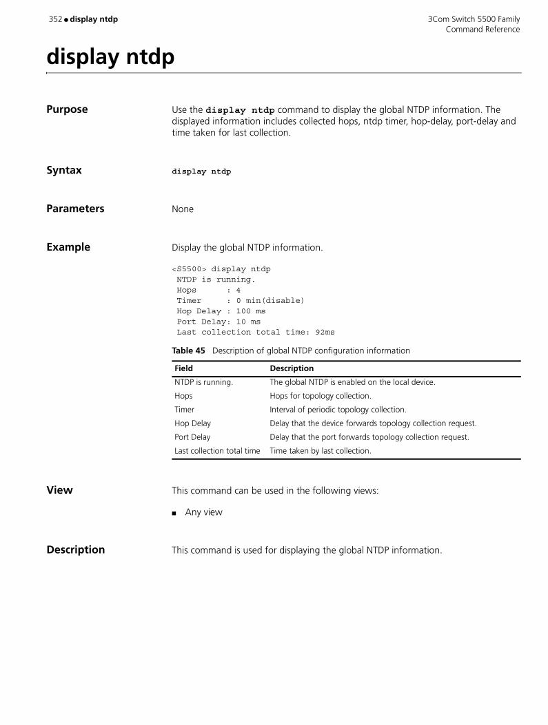
352 ● display ntdp 3Com Switch 5500 Family Command Reference
display ntdp
Purpose Use the display ntdp command to display the global NTDP information. The displayed information includes collected hops, ntdp timer, hop-delay, port-delay and time taken for last collection.
Syntax display ntdp
Parameters None
Example Display the global NTDP information.
<S5500> display ntdp NTDP is running. Hops : 4 Timer : 0 min(disable) Hop Delay : 100 ms Port Delay: 10 ms Last collection total time: 92ms
View This command can be used in the following views:
■ Any view
Description This command is used for displaying the global NTDP information.
Table 45 Description of global NTDP configuration information
Field Description
NTDP is running. The global NTDP is enabled on the local device.
Hops Hops for topology collection.
Timer Interval of periodic topology collection.
Hop Delay Delay that the device forwards topology collection request.
Port Delay Delay that the port forwards topology collection request.
Last collection total time Time taken by last collection.
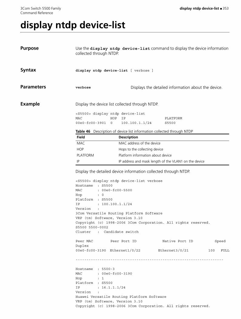
3Com Switch 5500 Family display ntdp device-list ● 353 Command Reference
display ntdp device-list
Purpose Use the display ntdp device-list command to display the device information collected through NTDP.
Syntax display ntdp device-list [ verbose ]
Parameters verbose Displays the detailed information about the device.
Example Display the device list collected through NTDP.
<S5500> display ntdp device-listMAC HOP IP PLATFORM00e0-fc00-3901 0 100.100.1.1/24 S5500
Table 46 Description of device list information collected through NTDP
Display the detailed device information collected through NTDP.
<S5500> display ntdp device-list verboseHostname : S5500MAC : 00e0-fc00-5500Hop : 0Platform : S5500IP : 100.100.1.1/24Version : 3Com Versatile Routing Platform Software VRP (tm) Software, Version 3.10 Copyright (c) 1998-2006 3Com Corporation. All rights reserved. S5500 5500-0002Cluster : Candidate switch
Peer MAC Peer Port ID Native Port ID Speed Duplex00e0-fc00-3190 Ethernet1/0/22 Ethernet3/0/21 100 FULL
--------------------------------------------------------------------
Hostname : 5500-3MAC : 00e0-fc00-3190Hop : 1Platform : S5500IP : 16.1.1.1/24Version :Huawei Versatile Routing Platform Software VRP (tm) Software, Version 3.10 Copyright (c) 1998-2006 3Com Corporation. All rights reserved.
Field Description
MAC MAC address of the device
HOP Hops to the collecting device
PLATFORM Platform information about device
IP IP address and mask length of the VLAN1 on the device
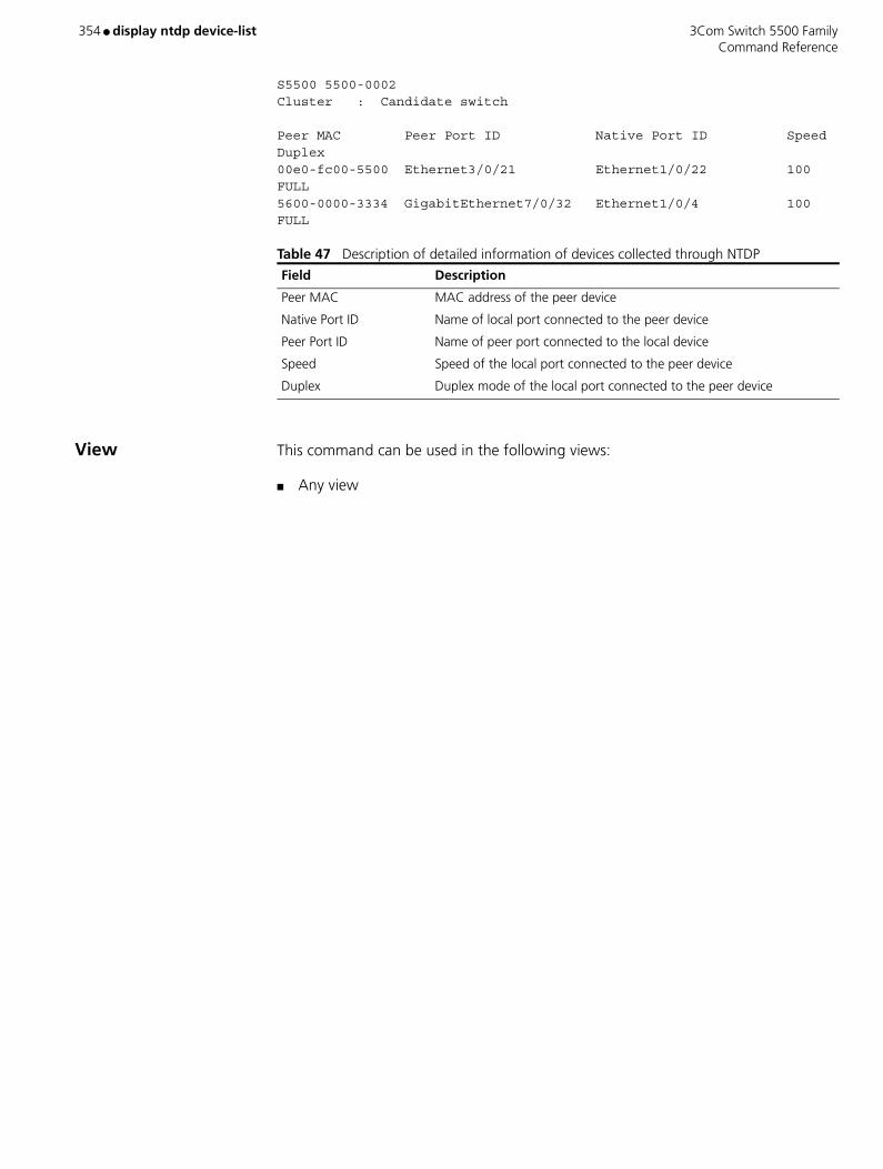
354 ● display ntdp device-list 3Com Switch 5500 Family Command Reference
S5500 5500-0002Cluster : Candidate switch
Peer MAC Peer Port ID Native Port ID Speed Duplex00e0-fc00-5500 Ethernet3/0/21 Ethernet1/0/22 100 FULL5600-0000-3334 GigabitEthernet7/0/32 Ethernet1/0/4 100 FULL
Table 47 Description of detailed information of devices collected through NTDP
View This command can be used in the following views:
■ Any view
Field Description
Peer MAC MAC address of the peer device
Native Port ID Name of local port connected to the peer device
Peer Port ID Name of peer port connected to the local device
Speed Speed of the local port connected to the peer device
Duplex Duplex mode of the local port connected to the peer device
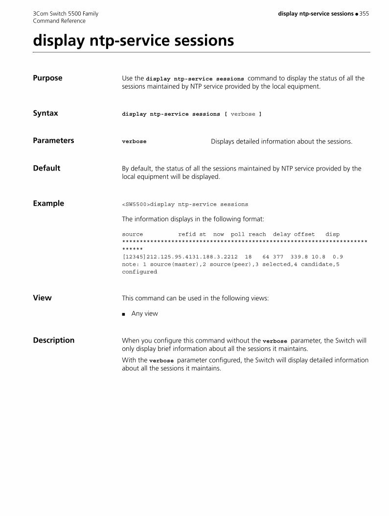
3Com Switch 5500 Family display ntp-service sessions ● 355 Command Reference
display ntp-service sessions
Purpose Use the display ntp-service sessions command to display the status of all the sessions maintained by NTP service provided by the local equipment.
Syntax display ntp-service sessions [ verbose ]
Parameters verbose Displays detailed information about the sessions.
Default By default, the status of all the sessions maintained by NTP service provided by the local equipment will be displayed.
Example <SW5500>display ntp-service sessions
The information displays in the following format:
source refid st now poll reach delay offset disp****************************************************************************[12345]212.125.95.4131.188.3.2212 18 64 377 339.8 10.8 0.9note: 1 source(master),2 source(peer),3 selected,4 candidate,5 configured
View This command can be used in the following views:
■ Any view
Description When you configure this command without the verbose parameter, the Switch will only display brief information about all the sessions it maintains.
With the verbose parameter configured, the Switch will display detailed information about all the sessions it maintains.

356 ● display ntp-service status 3Com Switch 5500 Family Command Reference
display ntp-service status
Purpose Use the command display ntp-service status to display the NTP service status.
Syntax display ntp-service status
Parameters None
Example <SW5500>display ntp-service status
The information displays in the following format:
clock status: unsynchronized clock stratum: 16 reference clock ID: none nominal frequency: 100.0000 Hz actual frequency: 100.0000 Hz clock precision: 2^17 clock offset: 0.0000 ms root delay: 0.00 ms root dispersion: 0.00 ms peer dispersion: 0.00 ms reference time: 00:00:00.000 UTC Jan 1 1900(00000000.00000000)
View This command can be used in the following views:
■ Any view.
Description The following table describes the outputs:
Table 48 NTP service status information
Output Meaning
clock status: unsynchronized Local clock status: do not synchronize to any remote NTP server.
clock stratum: 16 Indicates the NTP stratum of local clock
reference clock ID Indicates the address of a remote server of the reference ID, in the case that the local system has been synchronized by a remote NTP server or the ID of some clock source.
nominal frequency Nominal frequency of the local system hardware clock.
actual frequency Actual frequency of the local system hardware clock.
clock precision Precision of local system clock
clock offset Offsets of the local clock to the NTP server clock.
root delay Root delay from local equipment to the master reference clock.
root dispersion Dispersion of the local clock relative to the NTP server clock.
peer dispersion Dispersion of the remote NTP server.
reference time Reference timestamp.
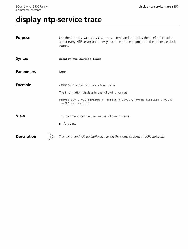
3Com Switch 5500 Family display ntp-service trace ● 357 Command Reference
display ntp-service trace
Purpose Use the display ntp-service trace command to display the brief information about every NTP server on the way from the local equipment to the reference clock source.
Syntax display ntp-service trace
Parameters None
Example <SW5500>display ntp-service trace
The information displays in the following format:
server 127.0.0.1,stratum 8, offset 0.000000, synch distance 0.00000 refid 127.127.1.0
View This command can be used in the following views:
■ Any view
Description This command will be ineffective when the switches form an XRN network.

358 ● display ospf abr-asbr 3Com Switch 5500 Family Command Reference
display ospf abr-asbr
Purpose Use the display ospf abr-asbr command to view information about the Area Border Router (ABR) and Autonomous System Border Router (ASBR) of OSPF.
Syntax display ospf [ process-id ] abr-asbr
Parameters process-id Specifies the process ID of OSPF. Valid values are 1 to 65535. The command is applied to all current OSPF processes if you do not specify a process ID.
Example To display information on the ABR and ASBR of OSPF, enter the following:
<SW5500>display ospf abr-asbrOSPF Process 1 with Router ID 10.110.98.138Routing Table to ABR and ASBR I = Intra i = Inter A = ASBR B = ABR S = SumASBRDestination Area Cost Nexthop InterfaceIA 2.2.2.2 0.0.0.0 10 10.153.17.89 Vlan-interface1
View This command can be used in the following views:
■ Any view
Table 49 Output Description of the ospf abr-asbr command
Field Description
Destination Router ID of the ABR or ASBR
Area Area where the router is connected with ASBR
Cost The routing overhead value of the route
Nexthop Nexthop address to the destination
Interface The local output interface

3Com Switch 5500 Family display ospf asbr-summary ● 359 Command Reference
display ospf asbr-summary
Purpose Use the display ospf asbr-summary command to view the summary information of an OSPF imported route, or all OSPF imported routes.
Syntax display ospf [ process-id ] asbr-summary [ ip_address mask ]
Parameters process-id Specifies the process ID of OSPF. Valid values are 1 to 65535. The command is applied to all current OSPF processes if you do not specify a process ID.
ip_address Specifies an IP address.
mask Specifies an IP subnet mask.
Example To display the summary information of all OSPF imported routes, enter the following:
<SW5500>display ospf asbr-summaryOSPF Process 1 with Router ID 1.1.1.1Summary AddressesTotal summary address count: 2
Summary Addressnet : 168.10.0.0mask : 255.254.0.0tag : 1status : AdvertiseThe Count of Route is 0
Summary Addressnet : 1.1.0.0mask : 255.255.0.0tag : 100status : DoNotAdvertiseThe Count of Route is 0
View This command can be used in the following views:
■ Any view
Table 50 Output Description of the display ospf abr-asbr summary command
Field Description
net Destination network segment
Mask IP subnet mask
tag Tag
status Status information including two values:
■ DoNotAdvertise — The summary routing information to the network segment will not be advertised.
■ Advertise — The summary routing information to the network segment will be advertised.

360 ● display ospf asbr-summary 3Com Switch 5500 Family Command Reference
Description If you do not specify an IP address and subnet mask, the summary information of all OSPF imported routes is displayed.
Related Command asbr-summary

3Com Switch 5500 Family display ospf brief ● 361 Command Reference
display ospf brief
Purpose Use the display ospf brief command to view OSPF summary information.
Syntax display ospf [ process-id ] brief
Parameters process-id Enter the process ID of OSPF Valid values are 1 to 65535. If no process ID is specified, the command is applied to all current OSPF processes.
Example To display OSPF summary information, enter the following:
<SW5500>display ospf briefOSPF Process 1 with Router ID 10.110.95.189OSPF Protocol Information
The information displays in the following format:
RouterID: 10.110.95.189 Border Router: AS spf-schedule-interval: 5 Routing preference: Inter/Intra: 10 External: 150 Default ASE parameters: Metric: 1 Tag: 0.0.0.1 Type: 2 SPF computation count: 16 Area Count: 1 Nssa Area Count: 0
Area 0.0.0.0: Authtype: none Flags: <> SPF scheduled: <> Interface: 201.1.1.4 (Vlan-interface1) Cost: 1 State: DR Type: Broadcast Priority: 1 Designated Router: 201.1.1.4 Backup Designated Router: 201.1.1.3Timers: Hello 10, Dead 40, Poll 0, Retransmit 5, Transmit Delay 1
Table 51 Output Description of the display ospf brief command
Field Description
RouterID Router ID of the router
Border Router Border routers for connection to the area, including autonomous system border router (ASBR) and area border router (ABR).
spf-schedule-interval Interval of SPF schedule.
Authtype Authentication type of OSPF.
Routing preference Routing preference of OSPF. The internal route of OSPF includes intra/inter area route, and its default routing preference is 10. While that of the external route of OSPF is 150 by default.
Default ASE parameters
Default ASE parameters of OSPF, including metric, type, and tag.
SPF computation count
SPF computation count since OSPF is enabled.
Area Count Areas connected to this router.

362 ● display ospf brief 3Com Switch 5500 Family Command Reference
View This command can be used in the following views:
■ Any view
Nssa Area Count Number of NSSA areas.
SPF scheduled SPF scheduled (flag).
Interface IP address of the interface.
Cost Cost of the interface.
State State information
Type OSPF network type of interface
Priority Priority of interface
Designated Router IP address of designated router
Backup Designated Router
IP address of backup designated router
Timers OSPF timers:
■ Hello — Interval of hello packets
■ Dead — Interval of dead neighbors
■ Poll — Interval of poll
■ Retransmit — Interval of retransmitting LSAs
■ Transmit delay — Delay time of transmitting LSAs
Table 51 Output Description of the display ospf brief command (continued)
Field Description

3Com Switch 5500 Family display ospf cumulative ● 363 Command Reference
display ospf cumulative
Purpose Use the display ospf cumulative command to view the OSPF cumulative information.
Syntax display ospf [ process-id ] cumulative
Parameters process-id Enter process ID of OSPF, ranging from 1 to 65535. The command is applied to all current OSPF processes if you do not specify a process ID.
Example To display the OSPF cumulative information, enter the following:
<SW5500>display ospf cumulativeOSPF Process 1 with Router ID 1.1.1.1
The information displays in the following format:
Cumulations
IO StatisticsType InputOutputHello 225437DB Description 7886Link-State Req 1818Link-State Update 4853Link-State Ack 2521ASE: 1 Checksum Sum: FCAF LSAs originated by this router
Router: 50 SumNet: 40SumASB: 2LSAs Originated: 92 LSAs Received: 33Area 0.0.00.0:
Neighbors: 1 Interfaces: 1Spf: 54 Checksum Sum F020rtr: 2 net: 0 sumasb: 0 sumnet: 1
Area 0.0.0.1:Neighbors: 0 Interfaces: 1Spf: 19 Checksum Sum 14EAD rtr: 1 net: 0sumasb: 1sumnet: 1
Routing Table:Intra Area: 2 Inter Area: 0ASE: 1
Table 52 Output Description of the display ospf cumulative command
Field Description
IO Statistics Type Type of input/output OSPF packet.
Input Number of received packets.
Output Number of transmitted packets.
ASE Number of all ASE LSAs.
checksum sum Checksum of ASE LSAs.
LSAs originated Number of originated LSAs.
received Number of received LSAs generated by other routers.
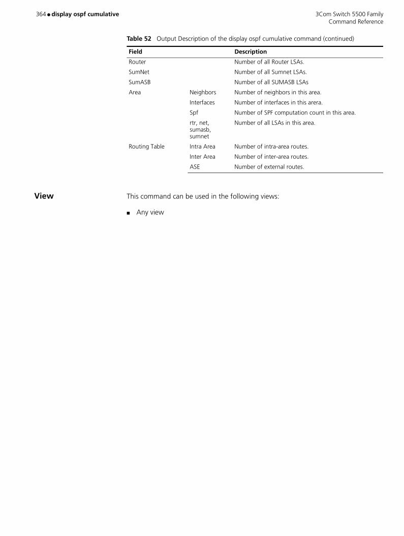
364 ● display ospf cumulative 3Com Switch 5500 Family Command Reference
View This command can be used in the following views:
■ Any view
Router Number of all Router LSAs.
SumNet Number of all Sumnet LSAs.
SumASB Number of all SUMASB LSAs
Area Neighbors Number of neighbors in this area.
Interfaces Number of interfaces in this arera.
Spf Number of SPF computation count in this area.
rtr, net, sumasb, sumnet
Number of all LSAs in this area.
Routing Table Intra Area Number of intra-area routes.
Inter Area Number of inter-area routes.
ASE Number of external routes.
Table 52 Output Description of the display ospf cumulative command (continued)
Field Description
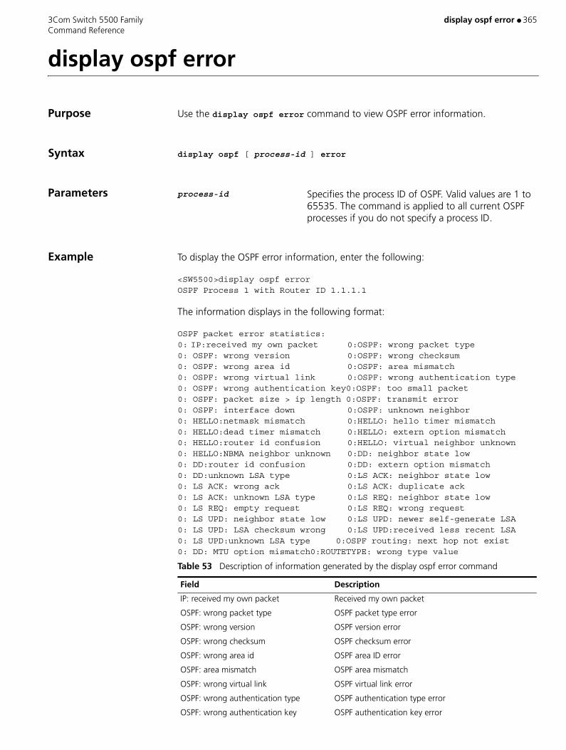
3Com Switch 5500 Family display ospf error ● 365 Command Reference
display ospf error
Purpose Use the display ospf error command to view OSPF error information.
Syntax display ospf [ process-id ] error
Parameters process-id Specifies the process ID of OSPF. Valid values are 1 to 65535. The command is applied to all current OSPF processes if you do not specify a process ID.
Example To display the OSPF error information, enter the following:
<SW5500>display ospf errorOSPF Process 1 with Router ID 1.1.1.1
The information displays in the following format:
OSPF packet error statistics:0: IP:received my own packet 0:OSPF: wrong packet type0: OSPF: wrong version 0:OSPF: wrong checksum0: OSPF: wrong area id 0:OSPF: area mismatch0: OSPF: wrong virtual link 0:OSPF: wrong authentication type0: OSPF: wrong authentication key0:OSPF: too small packet0: OSPF: packet size > ip length 0:OSPF: transmit error0: OSPF: interface down 0:OSPF: unknown neighbor0: HELLO:netmask mismatch 0:HELLO: hello timer mismatch0: HELLO:dead timer mismatch 0:HELLO: extern option mismatch0: HELLO:router id confusion 0:HELLO: virtual neighbor unknown0: HELLO:NBMA neighbor unknown 0:DD: neighbor state low0: DD:router id confusion 0:DD: extern option mismatch0: DD:unknown LSA type 0:LS ACK: neighbor state low0: LS ACK: wrong ack 0:LS ACK: duplicate ack0: LS ACK: unknown LSA type 0:LS REQ: neighbor state low0: LS REQ: empty request 0:LS REQ: wrong request0: LS UPD: neighbor state low 0:LS UPD: newer self-generate LSA0: LS UPD: LSA checksum wrong 0:LS UPD:received less recent LSA0: LS UPD:unknown LSA type 0:OSPF routing: next hop not exist0: DD: MTU option mismatch0:ROUTETYPE: wrong type value
Table 53 Description of information generated by the display ospf error command
Field Description
IP: received my own packet Received my own packet
OSPF: wrong packet type OSPF packet type error
OSPF: wrong version OSPF version error
OSPF: wrong checksum OSPF checksum error
OSPF: wrong area id OSPF area ID error
OSPF: area mismatch OSPF area mismatch
OSPF: wrong virtual link OSPF virtual link error
OSPF: wrong authentication type OSPF authentication type error
OSPF: wrong authentication key OSPF authentication key error
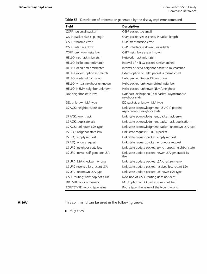
366 ● display ospf error 3Com Switch 5500 Family Command Reference
View This command can be used in the following views:
■ Any view
OSPF: too small packet OSPF packet too small
OSPF: packet size > ip length OSPF packet size exceeds IP packet length
OSPF: transmit error OSPF transmission error
OSPF: interface down OSPF interface is down, unavailable
OSPF: unknown neighbor OSPF neighbors are unknown
HELLO: netmask mismatch Network mask mismatch
HELLO: hello timer mismatch Interval of HELLO packet is mismatched
HELLO: dead timer mismatch Interval of dead neighbor packet is mismatched
HELLO: extern option mismatch Extern option of Hello packet is mismatched
HELLO: router id confusion Hello packet: Router ID confusion
HELLO: virtual neighbor unknown Hello packet: unknown virtual neighbor
HELLO: NBMA neighbor unknown Hello packet: unknown NBMA neighbor
DD: neighbor state low Database description (DD) packet: asynchronous neighbor state
DD: unknown LSA type DD packet: unknown LSA type
LS ACK: neighbor state low Link state acknowledgment (LS ACK) packet: asynchronous neighbor state
LS ACK: wrong ack Link state acknowledgment packet: ack error
LS ACK: duplicate ack Link state acknowledgment packet: ack duplication
LS ACK: unknown LSA type Link state acknowledgment packet: unknown LSA type
LS REQ: neighbor state low Link state request (LS REQ) packet
LS REQ: empty request Link state request packet: empty request
LS REQ: wrong request Link state request packet: erroneous request
LS UPD: neighbor state low Link state update packet: asynchronous neighbor state
LS UPD: newer self-generate LSA Link state update packet: newer LSA generated by itself
LS UPD: LSA checksum wrong Link state update packet: LSA checksum error
LS UPD:received less recent LSA Link state update packet: received less recent LSA
LS UPD: unknown LSA type Link state update packet: unknown LSA type
OSPF routing: next hop not exist Next hop of OSPF routing does not exist
DD: MTU option mismatch MTU option of DD packet is mismatched
ROUTETYPE: wrong type value Route type: the value of the type is wrong
Table 53 Description of information generated by the display ospf error command
Field Description
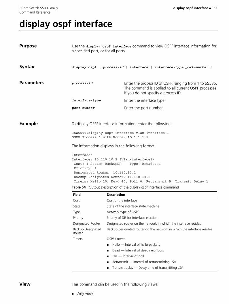
3Com Switch 5500 Family display ospf interface ● 367 Command Reference
display ospf interface
Purpose Use the display ospf interface command to view OSPF interface information for a specified port, or for all ports.
Syntax display ospf [ process-id ] interface [ interface-type port-number ]
Parameters process-id Enter the process ID of OSPF, ranging from 1 to 65535. The command is applied to all current OSPF processes if you do not specify a process ID.
interface-type Enter the interface type.
port-number Enter the port number.
Example To display OSPF interface information, enter the following:
<SW5500>display ospf interface vlan-interface 1OSPF Process 1 with Router ID 1.1.1.1
The information displays in the following format:
InterfacesInterface: 10.110.10.2 (Vlan-interface1) Cost: 1 State: BackupDR Type: Broadcast Priority: 1 Designated Router: 10.110.10.1 Backup Designated Router: 10.110.10.2 Timers: Hello 10, Dead 40, Poll 0, Retransmit 5, Transmit Delay 1
View This command can be used in the following views:
■ Any view
Table 54 Output Description of the display ospf interface command
Field Description
Cost Cost of the interface
State State of the interface state machine
Type Network type of OSPF
Priority Priority of DR for interface election
Designated Router Designated router on the network in which the interface resides
Backup Designated Router
Backup designated router on the network in which the interface resides
Timers OSPF timers:
■ Hello — Interval of hello packets
■ Dead — Interval of dead neighbors
■ Poll — Interval of poll
■ Retransmit — Interval of retransmitting LSA
■ Transmit delay — Delay time of transmitting LSA

368 ● display ospf interface 3Com Switch 5500 Family Command Reference
Description The information displayed includes OSPF configuration and running state.

3Com Switch 5500 Family display ospf lsdb ● 369 Command Reference
display ospf lsdb
Purpose Use the display ospf lsdb command to view database information about the OSPF connecting state.
Syntax display ospf [ process-id ] [ area_id ] lsdb [ brief | [ asbr | ase | network | nssa | router | summary ] [ ip_address ] [ originate-router ip_address | self-originate ]]
Parameters process-id Specifies the process ID of OSPF, ranging from 1 to 65535. The command is applied to all current OSPF processes if you do not specify a process ID.
area_id Specifies the ID of the OSPF area, as either an ID number or an IP address.
brief Enter to view brief information.
asbr Enter to view information about summary ASBR-LSA.
ase Enter to view information about AS-external-LSA.
network Enter to view information about the Network LSA.
nssa Enter to view information about the NSSA-external-LSA.
router Enter to view information about the Router-LSA.
summary Enter to view information about Summary-Net-LSA.
originate-router Enter to view information about the LSA generator.
self-originate Enter to view information about self-originated LSA.
Example To display database information about the OSPF connecting state, enter the following:
<SW5500>display ospf lsdbOSPF Process 1 with Router ID 1.1.1.1
The information displays in the following format:
Link State Database
Area: 0.0.0.0Type LinkState ID AdvRouter AgeLenSequenceMetricWhereRtr 2.2.2.2 2.2.2.2 46536 8000000c 0 SpfTreeRtr 1.1.1.1 1.1.1.1449 36 80000004 0 SpfTreeNet 10.153.17.89 2.2.2.2 465 32 80000004 0 SpfTreeSNet 10.153.18.0 1.1.1.1 35528 80000003 10 Inter ListArea: 0.0.0.1Type LinkState ID AdvRouter AgeLenSequence MetricWhereRtr 1.1.1.1 1.1.1.1 449 36 80000004 0 SpfTreeRtr 3.3.3.3 3.3.3.3 429 36 8000000a 0 ClistNet 10.153.18.89 3.3.3.3 429 32 80000003 0 SpfTreeSNet 10.153.17.0 1.1.1.1355 28 80000003 10 Inter List
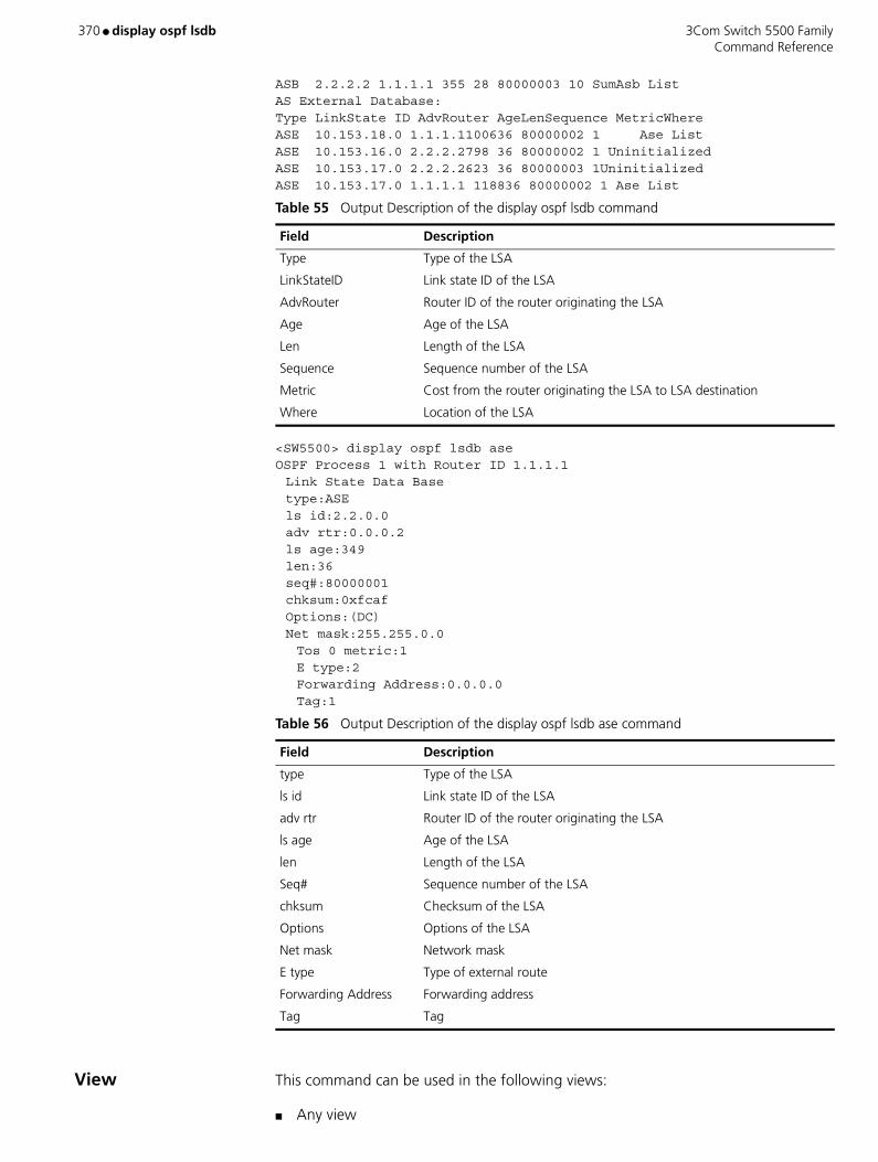
370 ● display ospf lsdb 3Com Switch 5500 Family Command Reference
ASB 2.2.2.2 1.1.1.1 355 28 80000003 10 SumAsb ListAS External Database:Type LinkState ID AdvRouter AgeLenSequence MetricWhereASE 10.153.18.0 1.1.1.1100636 80000002 1 Ase ListASE 10.153.16.0 2.2.2.2798 36 80000002 1 UninitializedASE 10.153.17.0 2.2.2.2623 36 80000003 1UninitializedASE 10.153.17.0 1.1.1.1 118836 80000002 1 Ase List
<SW5500> display ospf lsdb aseOSPF Process 1 with Router ID 1.1.1.1Link State Data Base type:ASE ls id:2.2.0.0adv rtr:0.0.0.2ls age:349len:36seq#:80000001chksum:0xfcaf Options:(DC) Net mask:255.255.0.0 Tos 0 metric:1E type:2Forwarding Address:0.0.0.0Tag:1
View This command can be used in the following views:
■ Any view
Table 55 Output Description of the display ospf lsdb command
Field Description
Type Type of the LSA
LinkStateID Link state ID of the LSA
AdvRouter Router ID of the router originating the LSA
Age Age of the LSA
Len Length of the LSA
Sequence Sequence number of the LSA
Metric Cost from the router originating the LSA to LSA destination
Where Location of the LSA
Table 56 Output Description of the display ospf lsdb ase command
Field Description
type Type of the LSA
ls id Link state ID of the LSA
adv rtr Router ID of the router originating the LSA
ls age Age of the LSA
len Length of the LSA
Seq# Sequence number of the LSA
chksum Checksum of the LSA
Options Options of the LSA
Net mask Network mask
E type Type of external route
Forwarding Address Forwarding address
Tag Tag
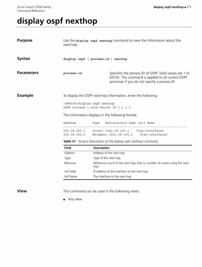
3Com Switch 5500 Family display ospf nexthop ● 371 Command Reference
display ospf nexthop
Purpose Use the display ospf nexthop command to view the information about the next-hop.
Syntax display ospf [ process-id ] nexthop
Parameters process-id Specifies the process ID of OSPF. Valid values are 1 to 65535. The command is applied to all current OSPF processes if you do not specify a process ID.
Example To display the OSPF next-hop information, enter the following:
<SW5500>display ospf nexthopOSPF Process 1 with Router ID 1.1.1.1
The information displays in the following format:
Address Type RefcountIntf Addr Intf Name--------------------------------------------------------------------202.38.160.1 Direct 3202.38.160.1 Vlan-interface2202.38.160.2 Neighbor 1202.38.160.1 Vlan-interface2
View This command can be used in the following views:
■ Any view
Table 57 Output Description of the display ospf nexthop Command
Field Description
Address Address of the next hop
Type Type of the next hop
Refcount Reference count of the next hop, that is, number of routes using the next hop
Intf Addr IP address of the interface to the next hop
Intf Name The interface to the next hop
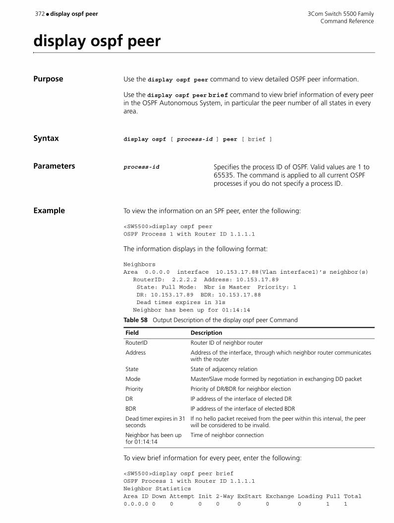
372 ● display ospf peer 3Com Switch 5500 Family Command Reference
display ospf peer
Purpose Use the display ospf peer command to view detailed OSPF peer information.
Use the display ospf peer brief command to view brief information of every peer in the OSPF Autonomous System, in particular the peer number of all states in every area.
Syntax display ospf [ process-id ] peer [ brief ]
Parameters process-id Specifies the process ID of OSPF. Valid values are 1 to 65535. The command is applied to all current OSPF processes if you do not specify a process ID.
Example To view the information on an SPF peer, enter the following:
<SW5500>display ospf peerOSPF Process 1 with Router ID 1.1.1.1
The information displays in the following format:
NeighborsArea 0.0.0.0 interface 10.153.17.88(Vlan interface1)’s neighbor(s)
RouterID: 2.2.2.2 Address: 10.153.17.89 State: Full Mode: Nbr is Master Priority: 1 DR: 10.153.17.89 BDR: 10.153.17.88 Dead times expires in 31sNeighbor has been up for 01:14:14
To view brief information for every peer, enter the following:
<SW5500>display ospf peer briefOSPF Process 1 with Router ID 1.1.1.1Neighbor StatisticsArea ID Down Attempt Init 2-Way ExStart Exchange Loading Full Total0.0.0.0 0 0 0 0 0 0 0 1 1
Table 58 Output Description of the display ospf peer Command
Field Description
RouterID Router ID of neighbor router
Address Address of the interface, through which neighbor router communicates with the router
State State of adjacency relation
Mode Master/Slave mode formed by negotiation in exchanging DD packet
Priority Priority of DR/BDR for neighbor election
DR IP address of the interface of elected DR
BDR IP address of the interface of elected BDR
Dead timer expires in 31 seconds
If no hello packet received from the peer within this interval, the peer will be considered to be invalid.
Neighbor has been up for 01:14:14
Time of neighbor connection

3Com Switch 5500 Family display ospf peer ● 373 Command Reference
0.0.0.1 0 0 0 0 0 0 0 1 1Total 0 0 0 0 0 0 0 2 2
View This command can be used in the following views:
■ Any view
Table 59 Output Description of the display ospf peer brief Command
Field Description
Area ID Area ID
Down The initial state for OSPF to establish neighbor relation, which indicates that the OSPF router has not received the message from a certain neighbor router within a period of time.
Attempt Enabled in the NBMA environment, such as Frame Relay, X.25 or ATM. It indicates that OSPF router has not received the message from a certain neighbor router within a period of time, but still attempts to send a Hello packet to the adjacent routers for their communications with a lower frequency.
Init Indicates that the OSPF router has received a Hello packet from a neighbor router, but its IP address is not contained in the Hello packet. Therefore, a two-way communication between them has not been established.
2-Way It indicates that a two-way communication between an OSPF router and a neighbor router has been established. DR and BDR can be selected in this state (or higher state)
ExStart In this state, the router determines the sequence number of the initial database description (DD) packet used for data exchange, so that it can obtain the latest link state information.
Exchange Indicates that the OSPF router sends DD packets to its neighbor routers to exchange link state information.
Loading In this state, OSPF router requests routes from the neighbor based on the updated link state information from neighbor routers and its expired information, and waits for response from neighbor routers.
Full Indicates that database synchronization between the routers has been completed, and their link state databases are consistent.

374 ● display ospf peer brief 3Com Switch 5500 Family Command Reference
display ospf peer brief
Purpose Use the display ospf peer brief command to display the brief information about the OSPF neighbors in different areas, including Router ID, interface, state, and so on.
Syntax display ospf [ process-id ] peer brief
Parameters process-id OSPF process ID. Valid values are 1 to 65535.
Example Display the brief information about OSPF neighbors in each area.
<S5500> display ospf peer brief OSPF Process 1 with Router ID 1.1.1.1 Neighbor Brief Information
Area 0.0.0.1:Router ID Address Pri DeadTime(s) Interface State2.2.2.2 192.168.0.2 1 39 Vlan-interface 1 Full/BDR
View This command can be used in the following views:
■ Any view
Table 60 Description on the fields of the display ospf peer brief command
Field Description
Router ID Router ID of the neighbor router
Address IP address of the interface adjacent to the neighbor router
Pri Priority of the neighbor router
DeadTime(s) Dead time (in seconds) of the neighbor router
Interface Type and number of the local router interface connected to the neighbor router
State State of the neighbor router:
"State/DR" is displayed in this field if the neighbor router is a designated router.
"State/BDR" is displayed in this field if the neighbor router is a backup designated router.
For the available states, refer to Table 2-2.
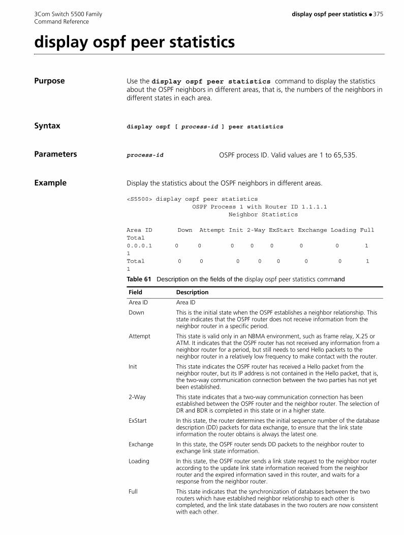
3Com Switch 5500 Family display ospf peer statistics ● 375 Command Reference
display ospf peer statistics
Purpose Use the display ospf peer statistics command to display the statistics about the OSPF neighbors in different areas, that is, the numbers of the neighbors in different states in each area.
Syntax display ospf [ process-id ] peer statistics
Parameters process-id OSPF process ID. Valid values are 1 to 65,535.
Example Display the statistics about the OSPF neighbors in different areas.
<S5500> display ospf peer statistics OSPF Process 1 with Router ID 1.1.1.1 Neighbor Statistics
Area ID Down Attempt Init 2-Way ExStart Exchange Loading Full Total0.0.0.1 0 0 0 0 0 0 0 1 1Total 0 0 0 0 0 0 0 1 1
Table 61 Description on the fields of the display ospf peer statistics command
Field Description
Area ID Area ID
Down This is the initial state when the OSPF establishes a neighbor relationship. This state indicates that the OSPF router does not receive information from the neighbor router in a specific period.
Attempt This state is valid only in an NBMA environment, such as frame relay, X.25 or ATM. It indicates that the OSPF router has not received any information from a neighbor router for a period, but still needs to send Hello packets to the neighbor router in a relatively low frequency to make contact with the router.
Init This state indicates the OSPF router has received a Hello packet from the neighbor router, but its IP address is not contained in the Hello packet, that is, the two-way communication connection between the two parties has not yet been established.
2-Way This state indicates that a two-way communication connection has been established between the OSPF router and the neighbor router. The selection of DR and BDR is completed in this state or in a higher state.
ExStart In this state, the router determines the initial sequence number of the database description (DD) packets for data exchange, to ensure that the link state information the router obtains is always the latest one.
Exchange In this state, the OSPF router sends DD packets to the neighbor router to exchange link state information.
Loading In this state, the OSPF router sends a link state request to the neighbor router according to the update link state information received from the neighbor router and the expired information saved in this router, and waits for a response from the neighbor router.
Full This state indicates that the synchronization of databases between the two routers which have established neighbor relationship to each other is completed, and the link state databases in the two routers are now consistent with each other.

376 ● display ospf peer statistics 3Com Switch 5500 Family Command Reference
View This command can be used in the following views:
■ Any view
Total Total numbers of the neighbors in different states
Table 61 Description on the fields of the display ospf peer statistics command (continued)
Field Description

3Com Switch 5500 Family display ospf request-queue ● 377 Command Reference
display ospf request-queue
Purpose Use the display ospf request-queue command to view information about the OSPF request-queue.
Syntax display ospf [ process-id ] request-queue
Parameters process-id Specifies the process ID of OSPF. Valid values are 1 to 65535. The command is applied to all current OSPF processes if you do not specify a process ID.
Example To display the information on the OSPF request-queue, enter the following:
<SW5500>display ospf request-queue
The information displays in the following format:
The Router’s Neighbors isRouterID:1.1.1.1Address:1.1.1.1Interface:1.1.1.3Area:0.0.0.0LSID:1.1.1.3AdvRouter:1.1.1.3 Sequence:80000017 Age:35
View This command can be used in the following views:
■ Any view
Table 62 Output Description of the display ospf request-queue command
Field Description
Router ID Router ID of neighbor router
Address Address of the interface, through which neighbor routers communicate with the router
Interface Address of the interface on the network segment
Area Area number of OSPF
LSID:1.1.1.3 Link State ID of the LSA
AdvRouter Router ID of the router originating the LSA
Sequence Sequence number of the LSA, used to discover old and repeated LSAs
Age Age of the LSA
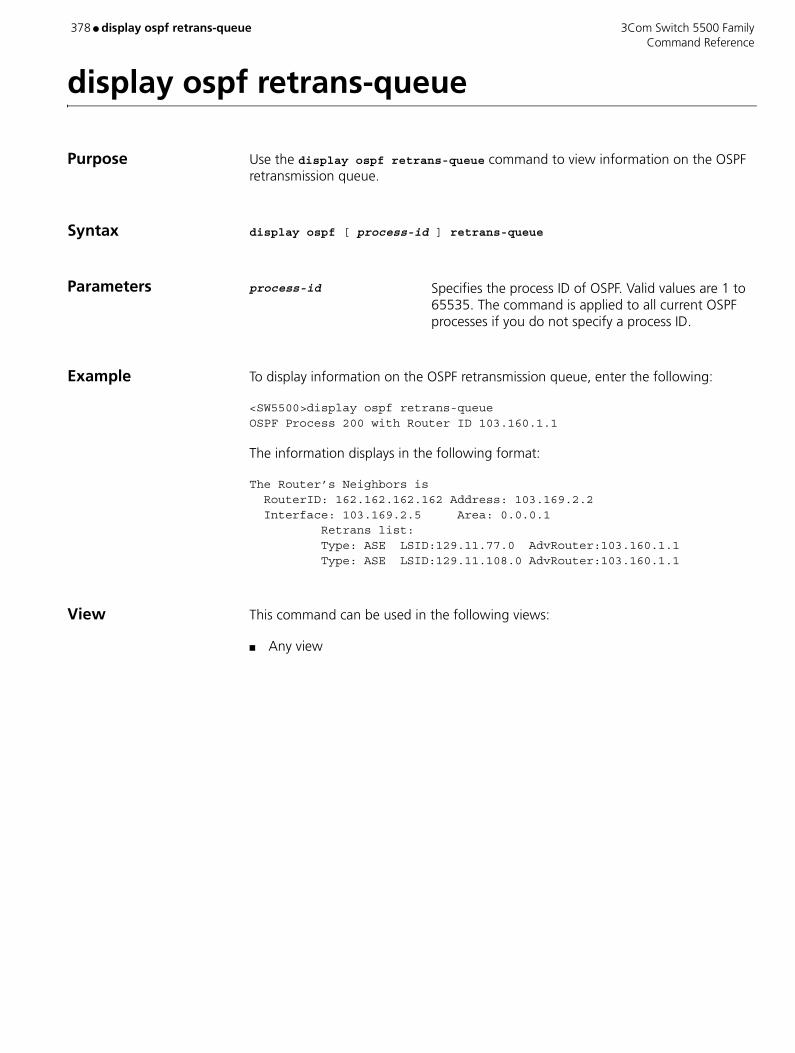
378 ● display ospf retrans-queue 3Com Switch 5500 Family Command Reference
display ospf retrans-queue
Purpose Use the display ospf retrans-queue command to view information on the OSPF retransmission queue.
Syntax display ospf [ process-id ] retrans-queue
Parameters process-id Specifies the process ID of OSPF. Valid values are 1 to 65535. The command is applied to all current OSPF processes if you do not specify a process ID.
Example To display information on the OSPF retransmission queue, enter the following:
<SW5500>display ospf retrans-queueOSPF Process 200 with Router ID 103.160.1.1
The information displays in the following format:
The Router’s Neighbors is RouterID: 162.162.162.162 Address: 103.169.2.2 Interface: 103.169.2.5 Area: 0.0.0.1 Retrans list: Type: ASE LSID:129.11.77.0 AdvRouter:103.160.1.1 Type: ASE LSID:129.11.108.0 AdvRouter:103.160.1.1
View This command can be used in the following views:
■ Any view

3Com Switch 5500 Family display ospf routing ● 379 Command Reference
display ospf routing
Purpose Use the display ospf routing command to view the information about the OSPF routing table.
Syntax display ospf [ process-id ] routing
Parameters process-id Specifies process ID of OSPF. Valid values are 1 to 65535. The command is applied to all current OSPF processes if you do not specify a process ID.
Example To view information on the OSPF routing table, enter the following:
<SW5500>display ospf routingOSPF Process 1 with Router ID 1.1.1.1
The information displays in the following format:
Routing tablesRouting for NetworkDestinationCostTypeNextHopAdvRouterArea10.110.0.0/161Net10.110.10.11.1.1.1010.10.0.0/16 1Stub10.10.0.13.3.3.30Total Nets: 2Intra Area: 2 Inter Area: 0 ASE: 0 NSSA: 0
View This command can be used in the following views:
■ Any view
Table 63 Output Description of the display ospf routing command
Field Description
Destination Destination of network segment
Cost Cost of route
Type Type of route
NextHop Next hop of route
AdvRouter Router ID of the router advertising the route
Area Area ID
Intra Area Number of intra-area routes
Inter Area Number of inter-area routes
ASE Number of external routes
NSSA Number of NSSA routes

380 ● display ospf vlink 3Com Switch 5500 Family Command Reference
display ospf vlink
Purpose Use the display ospf vlink command to view the information about OSPF virtual links.
Syntax display ospf [ process-id ] vlink
Parameters process-id Specifies the process ID of OSPF. Valid values are 1 to 65535. The command is applied to all current OSPF processes if you do not specify a process ID.
Example To view OSPF virtual links information, enter the following:
<SW5500>display ospf vlinkOSPF Process 1 with Router ID 1.1.1.1
The information displays in the following format:
Virtual linksVirtual-link Neighbor-id -> 2.2.2.2, State: Full Cost: 0 State: Full Type: Virtual Transit Area: 0.0.0.2 Timers: Hello 10, Dead 40, Poll 0, Retransmit 5, Transmit Delay 1
View This command can be used in the following views:
■ Any view
Table 64 Output Description of the display ospf vlink command
Field Description
Virtual-link Neighbor-id
Router ID of virtual-link neighbor router
State State
Interface IP address of the interface on the virtual link
Cost Route cost of the interface
Type Type: virtual link
Transit Area ID of transit area that the virtual link passes, and it cannot be backbone area, Stub area, or NSSA area
Timers OSPF timers:
n Hello — Interval of hello packets
n Dead — Interval of dead neighbors
n Poll — Interval of poll
n Retransmit — Interval of retransmitting LSA
n Transmit delay — Delay time of transmitting LSA
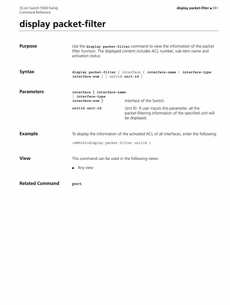
3Com Switch 5500 Family display packet-filter ● 381 Command Reference
display packet-filter
Purpose Use the display packet-filter command to view the information of the packet filter function. The displayed content includes ACL number, sub-item name and activation status.
Syntax display packet-filter { interface { interface-name | interface-type interface-num } | unitid unit-id }
Parameters interface { interface-name | interface-type interface-num } Interface of the Switch.
unitid unit-id Unit ID. If user inputs this parameter, all the packet-filtering information of the specified unit will be displayed.
Example To display the information of the activated ACL of all interfaces, enter the following:
<SW5500>display packet-filter unitid 1
View This command can be used in the following views:
■ Any view
Related Command port

382 ● display password-control 3Com Switch 5500 Family Command Reference
display password-control
Purpose Use the display password-control command to display the information about the global password control for all users.
Syntax display password-control
Parameters None
Example Display the information about the current password control for all users.
<S5500]> display password-controlGlobal password settings for all users:Password Aging: Enabled (90 days)Password Length: Enabled (10 Characters) Password History: Enabled (Max history-record num : 6)Password alert-before-expire : 7 daysPassword Authentication-timeout : 60 secondsPassword Attemp-failed action : Disable Password History was last reset 38 days ago.
The following table describes the output fields of the display password-control command.
View This command can be used in the following views:
■ Any view
Table 65 Description on the fields of the display password-control command
Field Description
Password Aging Password aging time
Password Length Minimum password length
Password history History password recording
Password alert-before-expire Alert time before password expiration
Password Authentication-timeout Timeout time for password authentication
Password Attemp-failed action Number of password attempts
History password was last reset 38 days ago
Time when the history password record was last cleared

3Com Switch 5500 Family display password-control blacklist ● 383 Command Reference
display password-control blacklist
Purpose Use the display password-control blacklist command to display the information about one or all users who have been added to the blacklist because of password attempt failure.
Syntax display password-control blacklist [ username username | ipaddress ip-address ]
Parameters username Name of the user who has been added to the blacklist.
ip-address IP address of the user who has been added to the blacklist.
Example Display the information about all the users who have been added to the blacklist because of password attempt failure.
<S5500]> display password-control blacklistUSERNAME IPJack 10.1.1.2The number of users in blacklist is :1
View This command can be used in the following views:
■ Any view
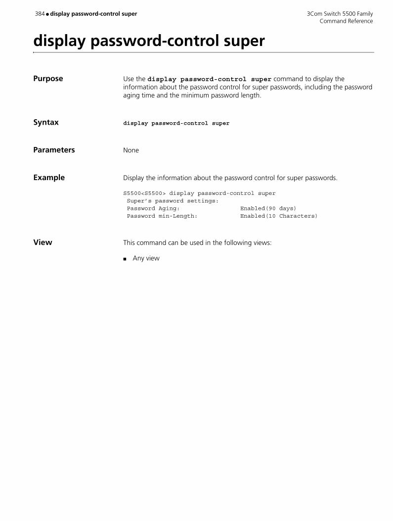
384 ● display password-control super 3Com Switch 5500 Family Command Reference
display password-control super
Purpose Use the display password-control super command to display the information about the password control for super passwords, including the password aging time and the minimum password length.
Syntax display password-control super
Parameters None
Example Display the information about the password control for super passwords.
S5500<S5500> display password-control super Super’s password settings: Password Aging: Enabled(90 days) Password min-Length: Enabled(10 Characters)
View This command can be used in the following views:
■ Any view

3Com Switch 5500 Family display pim bsr-info ● 385 Command Reference
display pim bsr-info
Purpose Use the display pim bsr-info to display the BSR information
Syntax display pim bsr-info
Parameters None
Example <SW5500>display pim bsr-infoCurrent BSR Address: 20.20.20.30Priority: 0Mask Length: 30Expires: 00:01:55Local host is BSR
Table 66 Output description of the display pim bsr command
View This command can be used in the following views:
■ Any view
Related Commands ■ c-bsr
■ c-rp
Field Description
BSR Boot strap router
Priority Priority of BSR
Mask Length:30 Length of mask
Expires:00:01:55 Expire Time
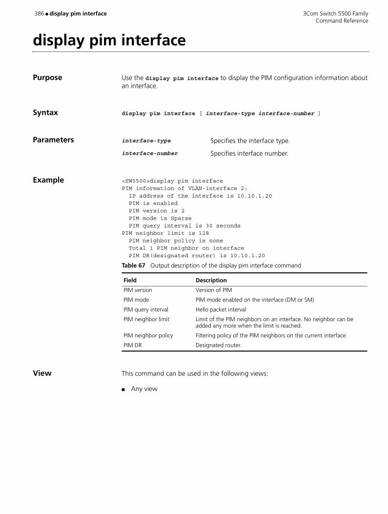
386 ● display pim interface 3Com Switch 5500 Family Command Reference
display pim interface
Purpose Use the display pim interface to display the PIM configuration information about an interface.
Syntax display pim interface [ interface-type interface-number ]
Parameters interface-type Specifies the interface type.
interface-number Specifies interface number.
Example <SW5500>display pim interfacePIM information of VLAN-interface 2: IP address of the interface is 10.10.1.20 PIM is enabled PIM version is 2 PIM mode is Sparse PIM query interval is 30 secondsPIM neighbor limit is 128 PIM neighbor policy is none Total 1 PIM neighbor on interface PIM DR(designated router) is 10.10.1.20
View This command can be used in the following views:
■ Any view
Table 67 Output description of the display pim interface command
Field Description
PIM version Version of PIM
PIM mode PIM mode enabled on the interface (DM or SM)
PIM query interval Hello packet interval
PIM neighbor limit Limit of the PIM neighbors on an interface. No neighbor can be added any more when the limit is reached.
PIM neighbor policy Filtering policy of the PIM neighbors on the current interface.
PIM DR Designated router.
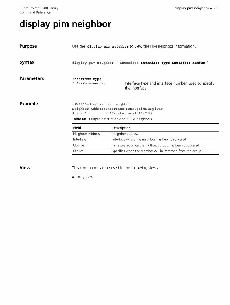
3Com Switch 5500 Family display pim neighbor ● 387 Command Reference
display pim neighbor
Purpose Use the display pim neighbor to view the PIM neighbor information.
Syntax display pim neighbor [ interface interface-type interface-number ]
Parameters interface-type interface-number Interface type and interface number, used to specify
the interface.
Example <SW5500>display pim neighborNeighbor AddressInterface NameUptime Expires8.8.8.6 VLAN-interface101637 89
View This command can be used in the following views:
■ Any view
Table 68 Output description about PIM neighbors
Field Description
Neighbor Address Neighbor address
Interface Interface where the neighbor has been discovered
Uptime Time passed since the multicast group has been discovered
Expires Specifies when the member will be removed from the group
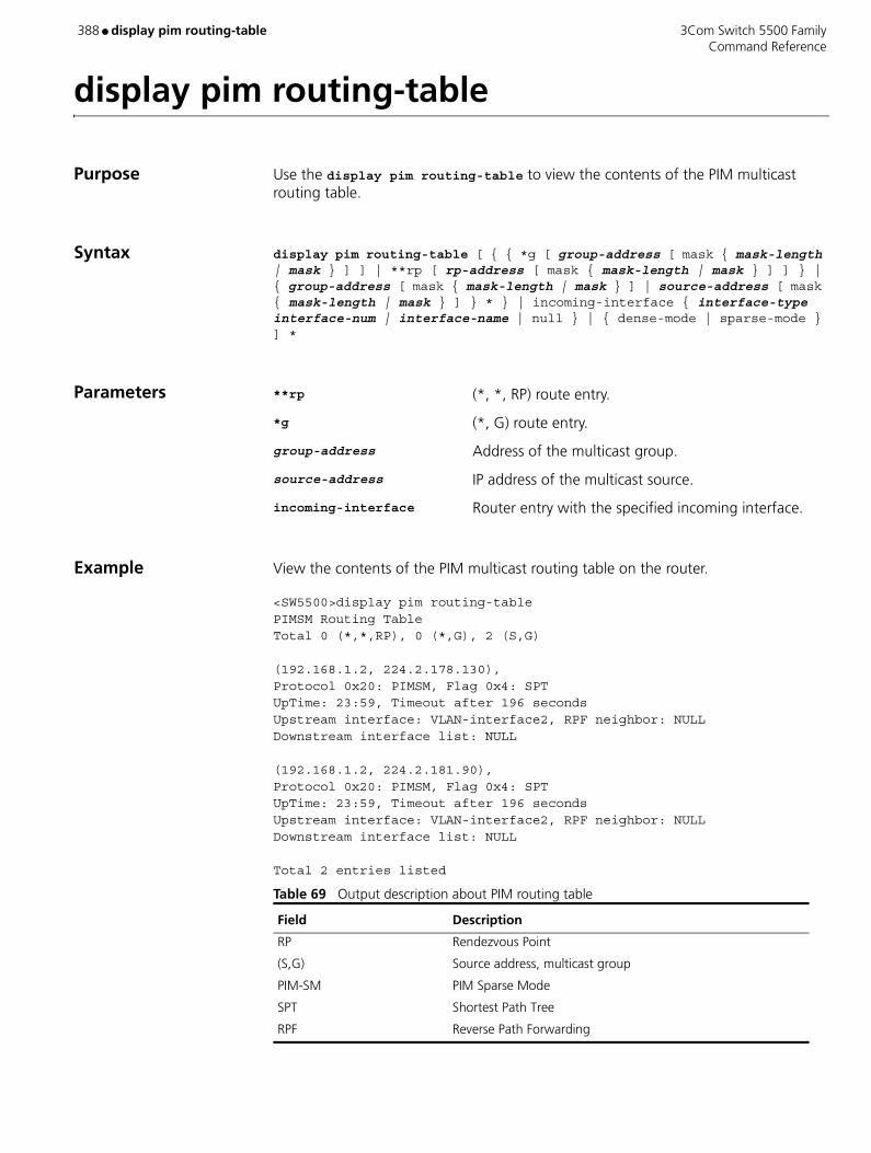
388 ● display pim routing-table 3Com Switch 5500 Family Command Reference
display pim routing-table
Purpose Use the display pim routing-table to view the contents of the PIM multicast routing table.
Syntax display pim routing-table [ { { *g [ group-address [ mask { mask-length | mask } ] ] | **rp [ rp-address [ mask { mask-length | mask } ] ] } | { group-address [ mask { mask-length | mask } ] | source-address [ mask { mask-length | mask } ] } * } | incoming-interface { interface-type interface-num | interface-name | null } | { dense-mode | sparse-mode } ] *
Parameters **rp (*, *, RP) route entry.
*g (*, G) route entry.
group-address Address of the multicast group.
source-address IP address of the multicast source.
incoming-interface Router entry with the specified incoming interface.
Example View the contents of the PIM multicast routing table on the router.
<SW5500>display pim routing-tablePIMSM Routing TableTotal 0 (*,*,RP), 0 (*,G), 2 (S,G)
(192.168.1.2, 224.2.178.130),Protocol 0x20: PIMSM, Flag 0x4: SPTUpTime: 23:59, Timeout after 196 secondsUpstream interface: VLAN-interface2, RPF neighbor: NULLDownstream interface list: NULL
(192.168.1.2, 224.2.181.90),Protocol 0x20: PIMSM, Flag 0x4: SPTUpTime: 23:59, Timeout after 196 secondsUpstream interface: VLAN-interface2, RPF neighbor: NULLDownstream interface list: NULL
Total 2 entries listed
Table 69 Output description about PIM routing table
Field Description
RP Rendezvous Point
(S,G) Source address, multicast group
PIM-SM PIM Sparse Mode
SPT Shortest Path Tree
RPF Reverse Path Forwarding

3Com Switch 5500 Family display pim routing-table ● 389 Command Reference
View This command can be used in the following views:
■ Any view
Related Command display multicast routing-table
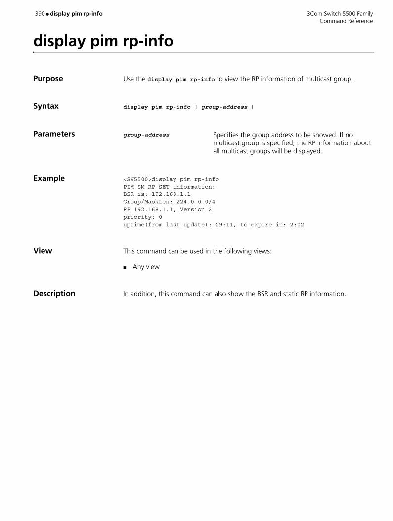
390 ● display pim rp-info 3Com Switch 5500 Family Command Reference
display pim rp-info
Purpose Use the display pim rp-info to view the RP information of multicast group.
Syntax display pim rp-info [ group-address ]
Parameters group-address Specifies the group address to be showed. If no multicast group is specified, the RP information about all multicast groups will be displayed.
Example <SW5500>display pim rp-infoPIM-SM RP-SET information:BSR is: 192.168.1.1Group/MaskLen: 224.0.0.0/4RP 192.168.1.1, Version 2priority: 0uptime(from last update): 29:11, to expire in: 2:02
View This command can be used in the following views:
■ Any view
Description In addition, this command can also show the BSR and static RP information.
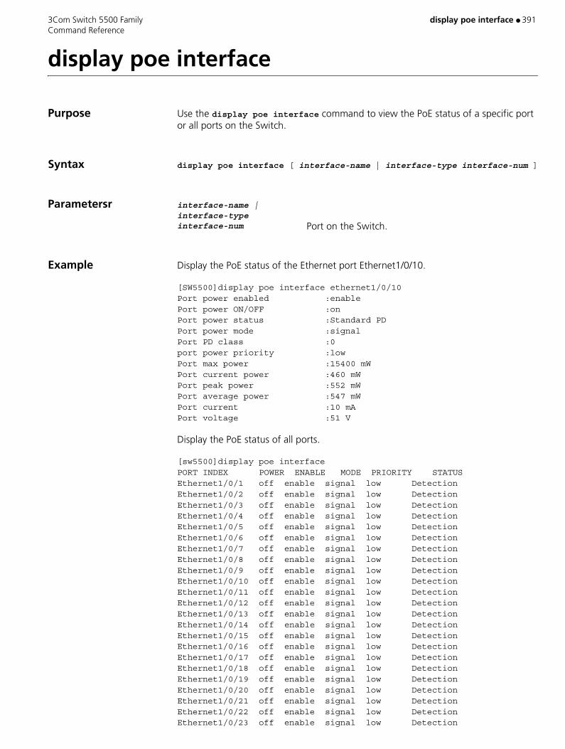
3Com Switch 5500 Family display poe interface ● 391 Command Reference
display poe interface
Purpose Use the display poe interface command to view the PoE status of a specific port or all ports on the Switch.
Syntax display poe interface [ interface-name | interface-type interface-num ]
Parametersr interface-name | interface-type interface-num Port on the Switch.
Example Display the PoE status of the Ethernet port Ethernet1/0/10.
[SW5500]display poe interface ethernet1/0/10 Port power enabled :enable Port power ON/OFF :on Port power status :Standard PD Port power mode :signal Port PD class :0 port power priority :low Port max power :15400 mW Port current power :460 mW Port peak power :552 mW Port average power :547 mW Port current :10 mA Port voltage :51 V
Display the PoE status of all ports.
[sw5500]display poe interfacePORT INDEX POWER ENABLE MODE PRIORITY STATUS Ethernet1/0/1 off enable signal low Detection Ethernet1/0/2 off enable signal low Detection Ethernet1/0/3 off enable signal low Detection Ethernet1/0/4 off enable signal low Detection Ethernet1/0/5 off enable signal low Detection Ethernet1/0/6 off enable signal low Detection Ethernet1/0/7 off enable signal low Detection Ethernet1/0/8 off enable signal low Detection Ethernet1/0/9 off enable signal low Detection Ethernet1/0/10 off enable signal low Detection Ethernet1/0/11 off enable signal low Detection Ethernet1/0/12 off enable signal low Detection Ethernet1/0/13 off enable signal low Detection Ethernet1/0/14 off enable signal low Detection Ethernet1/0/15 off enable signal low Detection Ethernet1/0/16 off enable signal low Detection Ethernet1/0/17 off enable signal low Detection Ethernet1/0/18 off enable signal low Detection Ethernet1/0/19 off enable signal low Detection Ethernet1/0/20 off enable signal low Detection Ethernet1/0/21 off enable signal low Detection Ethernet1/0/22 off enable signal low Detection Ethernet1/0/23 off enable signal low Detection

392 ● display poe interface 3Com Switch 5500 Family Command Reference
Ethernet1/0/24 off enable signal low Detection Ethernet1/0/25 off disable signal low User set off Ethernet1/0/26 off disable signal low User set off Ethernet1/0/27 off disable signal low User set off Ethernet1/0/28 off disable signal low User set off Ethernet1/0/29 off disable signal low User set off Ethernet1/0/30 off disable signal low User set off Ethernet1/0/31 off disable signal low User set off Ethernet1/0/32 off disable signal low User set off Ethernet1/0/33 off disable signal low User set off Ethernet1/0/34 off disable signal low User set off Ethernet1/0/35 off disable signal low User set off Ethernet1/0/36 off disable signal low User set off Ethernet1/0/37 off disable signal low User set off Ethernet1/0/38 off disable signal low User set off Ethernet1/0/39 off disable signal low User set off Ethernet1/0/40 off disable signal low User set off Ethernet1/0/41 off disable signal low User set off Ethernet1/0/42 off disable signal low User set off Ethernet1/0/43 off disable signal low User set off Ethernet1/0/44 off disable signal low User set off Ethernet1/0/45 off disable signal low User set off Ethernet1/0/46 off disable signal low User set off Ethernet1/0/47 off disable signal low User set off Ethernet1/0/48 off disable signal low User set off
View This command can be used in the following views:
■ Any view
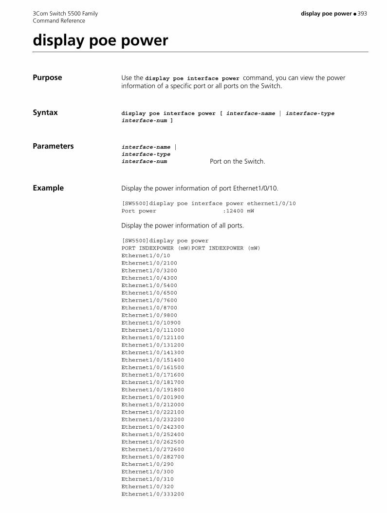
3Com Switch 5500 Family display poe power ● 393 Command Reference
display poe power
Purpose Use the display poe interface power command, you can view the power information of a specific port or all ports on the Switch.
Syntax display poe interface power [ interface-name | interface-type interface-num ]
Parameters interface-name | interface-type interface-num Port on the Switch.
Example Display the power information of port Ethernet1/0/10.
[SW5500]display poe interface power ethernet1/0/10Port power :12400 mW
Display the power information of all ports.
[SW5500]display poe powerPORT INDEXPOWER (mW)PORT INDEXPOWER (mW)Ethernet1/0/10Ethernet1/0/2100 Ethernet1/0/3200Ethernet1/0/4300 Ethernet1/0/5400Ethernet1/0/6500 Ethernet1/0/7600Ethernet1/0/8700 Ethernet1/0/9800Ethernet1/0/10900 Ethernet1/0/111000Ethernet1/0/121100 Ethernet1/0/131200Ethernet1/0/141300 Ethernet1/0/151400Ethernet1/0/161500 Ethernet1/0/171600Ethernet1/0/181700 Ethernet1/0/191800Ethernet1/0/201900 Ethernet1/0/212000Ethernet1/0/222100 Ethernet1/0/232200Ethernet1/0/242300 Ethernet1/0/252400Ethernet1/0/262500 Ethernet1/0/272600Ethernet1/0/282700 Ethernet1/0/290Ethernet1/0/300 Ethernet1/0/310Ethernet1/0/320 Ethernet1/0/333200

394 ● display poe power 3Com Switch 5500 Family Command Reference
Ethernet1/0/343300 Ethernet1/0/353400Ethernet1/0/363500 Ethernet1/0/373600Ethernet1/0/383700 Ethernet1/0/393800Ethernet1/0/403900 Ethernet1/0/414000Ethernet1/0/424100 Ethernet1/0/434200Ethernet1/0/444300 Ethernet1/0/454400Ethernet1/0/464500 Ethernet1/0/474600Ethernet1/0/484700
View This command can be used in the following views:
■ Any view
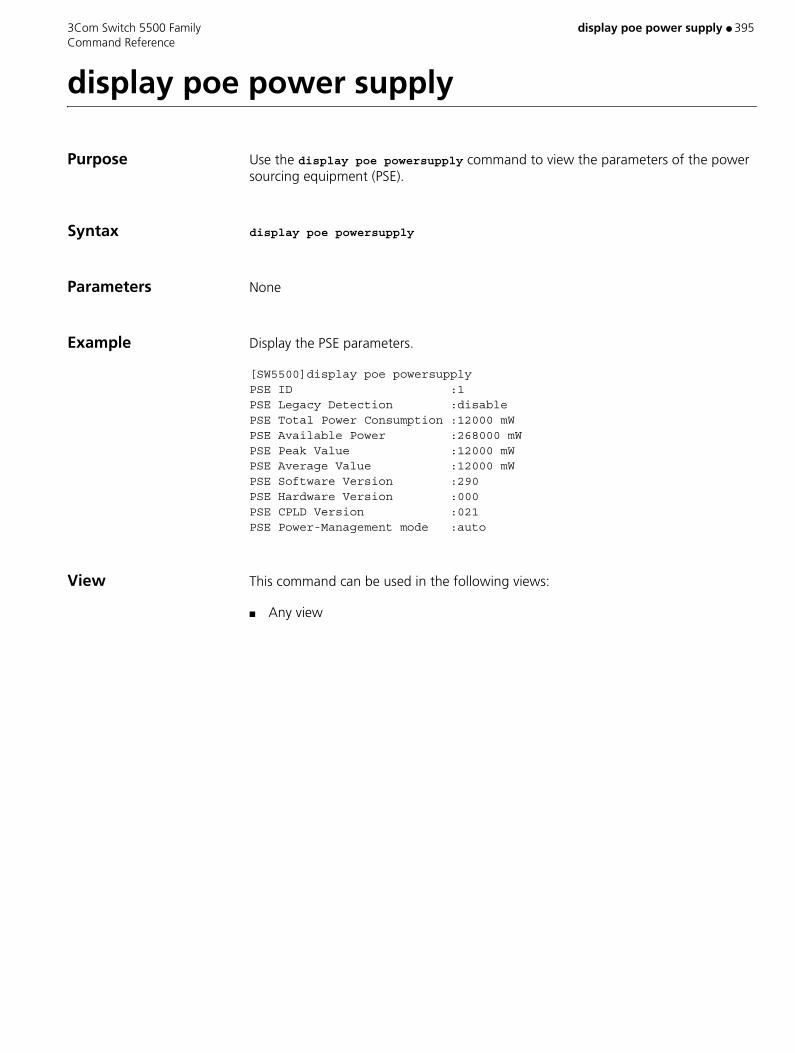
3Com Switch 5500 Family display poe power supply ● 395 Command Reference
display poe power supply
Purpose Use the display poe powersupply command to view the parameters of the power sourcing equipment (PSE).
Syntax display poe powersupply
Parameters None
Example Display the PSE parameters.
[SW5500]display poe powersupplyPSE ID :1 PSE Legacy Detection :disable PSE Total Power Consumption :12000 mW PSE Available Power :268000 mW PSE Peak Value :12000 mW PSE Average Value :12000 mW PSE Software Version :290 PSE Hardware Version :000 PSE CPLD Version :021 PSE Power-Management mode :auto
View This command can be used in the following views:
■ Any view

396 ● display poe-profile 3Com Switch 5500 Family Command Reference
display poe-profile
Purpose Use the display poe-profile command to display detailed configuration information of the created PoE Profile for a switch.
Syntax display poe-profile { all-profile | interface interface-type interface-number | name profilename }
Parameters interface-type Indicates type of the interface,
interface-number Specifies the port ID.
profilename Name of the PoE Profile to be displayed, consisting of a string 1 to 15 characters long. The profilename cannot be reserved keywords like all, interface, user, undo, user-based, port-based.
Example Display detailed configuration information for the PoE Profile by the name of profile-test.
<S5500> system-viewSystem View: return to User View with Ctrl+Z.[S5500] display poe-profile name profile-test
View This command can be used in the following views:
■ Any view

3Com Switch 5500 Family display port ● 397 Command Reference
display port
Purpose Use the display port hybrid command to view the ports whose link type is hybrid. Use the display port trunk command to view the ports whose link type is trunk.
Syntax display port { hybrid | trunk }
Parameters hybrid Displays the hybrid ports.
trunk Displays the trunked ports.
Example To display the currently configured hybrid ports, enter the following:
<SW5500>display port hybrid
The details display in the following format:
The following hybrid ports exist: Ethernet1/0/1 Ethernet1/0/2
This example indicates that the current configuration has two hybrid ports, Ethernet1/0/1 and Ethernet1/0/2.
View This command can be used in the following views:
■ Any view

398 ● display port-security 3Com Switch 5500 Family Command Reference
display port-security
Purpose Use the display port-security command to display the information about port security configuration (including global configuration and all or specific port configuration).
Syntax display port-security [ interface interface-list ]
Parameters interface interface-list Specifies an Ethernet port list, which can contain multiple Ethernet ports. The interface-list argument is in the format of { interface-type interface-number [ to interface-type interface-number ] } & < 1-10 >, where interface-type represents a port type, interface-number represents a port number, and & < 1-10 > means you can specify up to 10 ports or port ranges.
Example Display the security configuration on Ethernet1/0/1 port.
<S5500> display port-security interface Ethernet1/0/1 Equipment port security is enabled addressLearn trap is Enabled Violation trap is Enabled dot1x logon trap is Enabled dot1x logoff trap is Enabled dot1x logfailure trap is Enabled vlan id assigned is NULL OUI value: Index is 1, OUI value is 00efec
Ethernet1/0/1 is link-up port mode is Userlogin NeedtoKnow mode is disabled Intrusion mode is disableportTemporarily max mac-address num is 0
Table 70 Description on the fields of the display port-security command
Field Description
Equipment port security is enabled The port security feature is enabled on the switch.
addressLearn trap is Enabled The sending of MAC address learning trap messages is enabled.
Violation trap is Enabled The sending of intrusion detection trap messages is enabled.
dot1x logon trap is Enabled The sending of 802.1x user logon (authentication success) trap messages is enabled.
dot1x logoff trap is Enabled The sending of 802.1x user logoff trap messages is enabled.
dot1x logfailure trap is Enabled The sending of 802.1x user authentication failure trap messages is enabled.
vlan id assigned is NULL The delived VLAN ID is Null.

3Com Switch 5500 Family display port-security ● 399 Command Reference
View This command can be used in the following views:
■ Any view
Description Use the display port-security command to display the information about port security configuration (including global configuration and all or specific port configuration).
By checking the output of this command, you can verify the current configuration.
CAUTION:
■ This command will display global and all ports’ security configuration information if the interface-list argument is not specified.
■ This command will display global and particular port’s security configuration information if the interface-list argument is specified.
Index is 1, OUI value is 00efec The OUI value is 00efec and the OUI index is 1.
Ethernet1/0/1 is link-up The link state of port Ethernet 1/0/1 is up.
port mode is Userlogin The security mode of the port is Userlogin.
NeedtoKnow mode is disabled The NTK feature is disabled.
Intrusion mode is disableportTemporarily The intrusion detection action mode is disableportTemporarily.
max mac-address num is 0 The maximum number of MAC addresses allowed to access the port is zero, that is, there is no limit on the number of access users.
stored mac-address num is 0 The number of current users is zero.
Table 70 Description on the fields of the display port-security command (continued)
Field Description

400 ● display port vlan-vpn 3Com Switch 5500 Family Command Reference
display port vlan-vpn
Purpose Use the display port vlan-vpn command to display the information about VLAN VPN configuration of the current system, including current IPID value, VLAN-VPN ports, VLAN-VPN uplink ports and whether the inner tag priority replication function is enabled.
Syntax display port vlan-vpn
Parameters None
Example Display the VLAN-VPN configuration of the system.
<S5500> display port vlan-vpn Ethernet1/0/1 VLAN-VPN TPID: 8100
Ethernet1/0/2 VLAN-VPN status: enabled VLAN-VPN VLAN: 1 VLAN-VPN inner-cos-trust status: disable VLAN-VPN TPID: 8100
Ethernet1/0/3 VLAN-VPN TPID: 8100
Ethernet1/0/4 VLAN-VPN TPID: 8100…………………………(Omitted)
View This command can be used in the following views:
■ Any view
3Com Switch 5500 Family display power ● 401 Command Reference
display power
Purpose Use the display power command to display the working state of the built-in power supply.
Syntax display power [ unit unit-id ][ power-ID ]
Parameters unit unit-id Specifies the Unit ID of the switch
power-ID Power ID.
Example Show power state.
<SW5500>display power 1Unit1power 1 State: Normal
View This command can be used in the following views:
■ Any view

402 ● display protocol-priority 3Com Switch 5500 Family Command Reference
display protocol-priority
Purpose Use the display protocol-priority command to display the priority of protocol packets.
Syntax display protocol-priority
Parameters None
Example Display the priority of protocol packets.
<S5500> display protocol-priority
View This command can be used in the following views:
■ Any view
3Com Switch 5500 Family display protocol-vlan interface ● 403 Command Reference
display protocol-vlan interface
Purpose Use the display protocol-vlan interface command to display the protocol information and protocol indexes configured for specified ports.
Syntax display protocol-vlan interface { { interface-type interface-number [ to interface-type interface-number ] } | all }
Parameters { interface-type interface-number [ to interface-type interface-number ] } Ranges of Ports, the protocol-related information
about which is to be displayed. The to keyword specifies a port number range. If you do not specify this keyword, this argument specifies a single port. The interface-type argument is port type, and interface-num is port number.
all Displays the protocol-related information about all ports.
Example Display protocol information and protocol index configured for Ethernet1/0/1 and Ethernet1/0/2 ports.
<S5500> display protocol-vlan interface ethernet1/0/1 to ethernet1/0/2Interface: Ethernet1/0/1VLAN ID Protocol-Index Protocol-type50 1 ip 80 2 ip 100 1 ip 100 2 ipx ethernetiiInterface: Ethernet1/0/2VLAN ID Protocol-Index Protocol-type50 2 ipx raw80 1 at100 3 mode snap etype 0x0abc100 5 mode llc dsap 0xac ssap 0xbd
View This command can be used in the following views:
■ Any view‘
404 ● display protocol-vlan vlan 3Com Switch 5500 Family Command Reference
display protocol-vlan vlan
Purpose Use the display protocol-vlan vlan command to display the protocol information and protocol indexes configured for specified VLANs.
Syntax display protocol-vlan vlan { vlan-id [ to vlan-id ] | all }
Parameters vlan-id VLAN ID. Valid values are 1 to 4,094.
to Specifies a VLAN ID range. Make sure the vlan-id argument to the right of this keyword is larger than or equal to the argument to the left of this keyword.
all Specifies all VLANs.
Example Display the protocol information and protocol indexes configured for VLAN 10 through VLAN 20.
<S5500> display protocol-vlan vlan 10 to 20VLAN ID: 10VLAN Type: Protocol-based VLAN Protocol-Index Protocol-Type 1 IP 2 IP 3 IPX ETH II 4 ATVLAN ID: 15VLAN Type: Protocol-based VLAN Protocol-Index Protocol-Type 1 ip 2 mode snap etype 0x0abc
View This command can be used in the following views:
■ Any view
Related Command display vlan
3Com Switch 5500 Family display qos cos-local-precedence-map ● 405 Command Reference
display qos cos-local-precedence-map
Purpose Use the display qos cos-local-precedence-map command to view COS and Local-precedence map
Syntax display qos cos-local-precedence-map
Parameters None
Example Display COS and Local-precedence map.
<SW5500>display qos cos-local-precedence-mapcos-local-precedence-map: 802.1p & local precedence : 0 1 2 3 4 5 6 7-------------------------------------------------------------------- queue: 2 0 1 3 4 5 6 7
View This command can be used in the following views:
■ Any view

406 ● display qos-interface all 3Com Switch 5500 Family Command Reference
display qos-interface all
Purpose Use the display qos-interface all command to display all the QoS settings of the port.
Syntax display qos-interface { interface-name | interface-type interface-num | unit-id } all
Parameters interface-name | interface-type interface-num Specifies the port of the switch. Specify this parameter
and the switch will display the parameter configurations of the specified port.
unit-id Specifies the unit ID. Specify this parameter and the switch will display the parameter configurations of the specified unit.
Example Display all the configurations of QoS parameters for unit 1.
<SW5500> display qos-interface 1 allEthernet1/0/1: traffic-limit Inbound: Matches: Acl 2000 rule 0 running Target rate: 128 Kbps Exceed action: remark-dscp 63Ethernet1/0/1: traffic-priority Inbound: Matches: Acl 2000 rule 0 running Priority action: cos best-effortEthernet1/0/1: traffic-redirect Inbound: Matches: Acl 2000 rule 0 running Redirected to: interface Ethernet1/0/2Ethernet1/0/1: traffic-statistic Inbound: Matches: Acl 2000 rule 0 running 0 packet inprofile 0 packet outprofileEthernet1/0/1: mirrored-to Inbound: Matches: Acl 2000 rule 0 running---- More ----
View This command can be used in the following views:
■ Any view
Description If you do not input interface parameters, this command will display all QoS setting information for the Switch, including traffic policing, rate limit at interface, and so on.

3Com Switch 5500 Family display qos-interface all ● 407 Command Reference
If you input interface parameters, this command will display QoS setting information of the specified interfaces, including traffic policing, rate limit at interfaces, and so on.
Related Command port
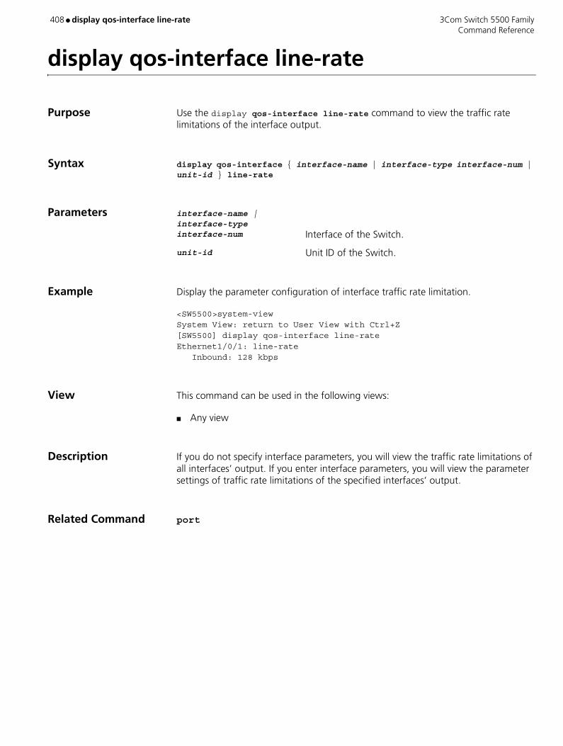
408 ● display qos-interface line-rate 3Com Switch 5500 Family Command Reference
display qos-interface line-rate
Purpose Use the display qos-interface line-rate command to view the traffic rate limitations of the interface output.
Syntax display qos-interface { interface-name | interface-type interface-num | unit-id } line-rate
Parameters interface-name | interface-type interface-num Interface of the Switch.
unit-id Unit ID of the Switch.
Example Display the parameter configuration of interface traffic rate limitation.
<SW5500>system-viewSystem View: return to User View with Ctrl+Z[SW5500] display qos-interface line-rate Ethernet1/0/1: line-rate Inbound: 128 kbps
View This command can be used in the following views:
■ Any view
Description If you do not specify interface parameters, you will view the traffic rate limitations of all interfaces’ output. If you enter interface parameters, you will view the parameter settings of traffic rate limitations of the specified interfaces’ output.
Related Command port

3Com Switch 5500 Family display qos-interface mirrored-to ● 409 Command Reference
display qos-interface mirrored-to
Purpose Use the display qos-interface mirrored-to command to view the settings of the traffic mirror.
Syntax display qos-interface { interface-name | interface-type interface-num | unit-id } mirrored-to
Parameters interface-name | interface-type interface-num Interface of the Switch, for detailed description, refer
to the port command in this manual.
unit-id Unit ID of the Switch.
Example To display the settings of traffic mirror, enter the following:
<SW5500> display qos-interface ethernet1/0/1 mirrored-toEthernet1/0/1: mirrored-to Inbound: Matches: Acl 2000 rule 0 running Mirrored to: monitor interface
View This command can be used in the following views:
■ Any view
Description This command is used for displaying the settings of traffic mirror. The information displayed includes the ACL of traffic to be mirrored and the observing port.
Related Commands ■ mirrored-to
■ port
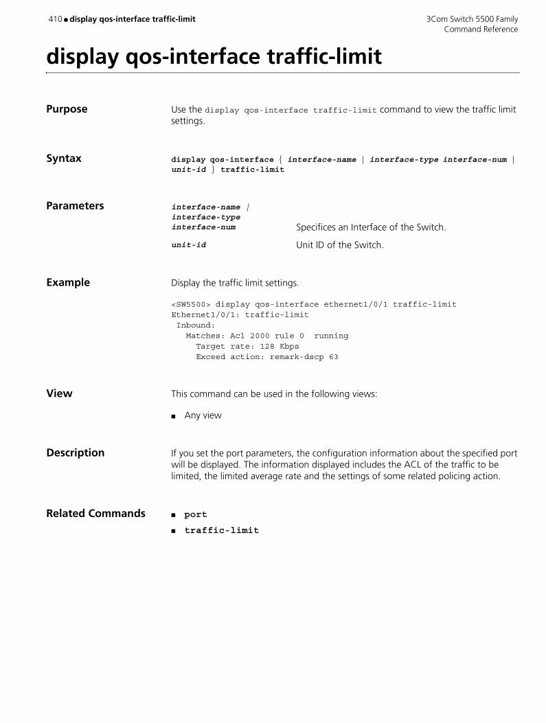
410 ● display qos-interface traffic-limit 3Com Switch 5500 Family Command Reference
display qos-interface traffic-limit
Purpose Use the display qos-interface traffic-limit command to view the traffic limit settings.
Syntax display qos-interface { interface-name | interface-type interface-num | unit-id } traffic-limit
Parameters interface-name | interface-type interface-num Specifices an Interface of the Switch.
unit-id Unit ID of the Switch.
Example Display the traffic limit settings.
<SW5500> display qos-interface ethernet1/0/1 traffic-limitEthernet1/0/1: traffic-limit Inbound: Matches: Acl 2000 rule 0 running Target rate: 128 Kbps Exceed action: remark-dscp 63
View This command can be used in the following views:
■ Any view
Description If you set the port parameters, the configuration information about the specified port will be displayed. The information displayed includes the ACL of the traffic to be limited, the limited average rate and the settings of some related policing action.
Related Commands ■ port
■ traffic-limit
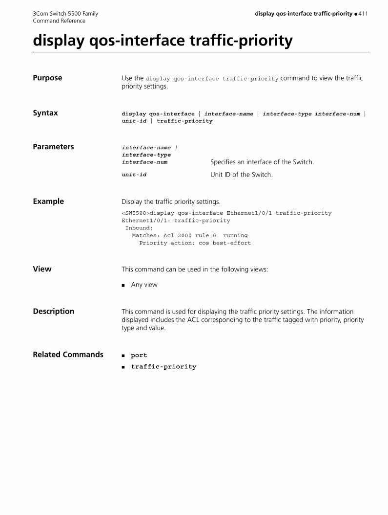
3Com Switch 5500 Family display qos-interface traffic-priority ● 411 Command Reference
display qos-interface traffic-priority
Purpose Use the display qos-interface traffic-priority command to view the traffic priority settings.
Syntax display qos-interface { interface-name | interface-type interface-num | unit-id } traffic-priority
Parameters interface-name | interface-type interface-num Specifies an interface of the Switch.
unit-id Unit ID of the Switch.
Example Display the traffic priority settings.
<SW5500>display qos-interface Ethernet1/0/1 traffic-priorityEthernet1/0/1: traffic-priority Inbound: Matches: Acl 2000 rule 0 running Priority action: cos best-effort
View This command can be used in the following views:
■ Any view
Description This command is used for displaying the traffic priority settings. The information displayed includes the ACL corresponding to the traffic tagged with priority, priority type and value.
Related Commands ■ port
■ traffic-priority
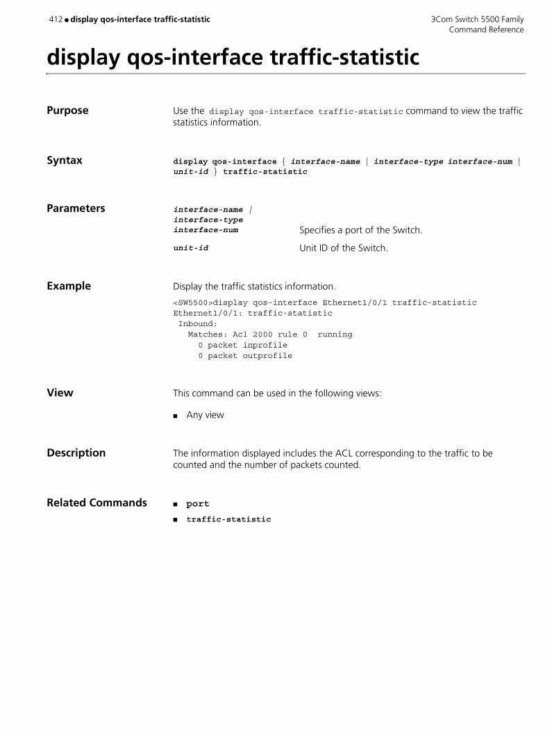
412 ● display qos-interface traffic-statistic 3Com Switch 5500 Family Command Reference
display qos-interface traffic-statistic
Purpose Use the display qos-interface traffic-statistic command to view the traffic statistics information.
Syntax display qos-interface { interface-name | interface-type interface-num | unit-id } traffic-statistic
Parameters interface-name | interface-type interface-num Specifies a port of the Switch.
unit-id Unit ID of the Switch.
Example Display the traffic statistics information.
<SW5500>display qos-interface Ethernet1/0/1 traffic-statisticEthernet1/0/1: traffic-statistic Inbound: Matches: Acl 2000 rule 0 running 0 packet inprofile 0 packet outprofile
View This command can be used in the following views:
■ Any view
Description The information displayed includes the ACL corresponding to the traffic to be counted and the number of packets counted.
Related Commands ■ port
■ traffic-statistic

3Com Switch 5500 Family display qos-profile ● 413 Command Reference
display qos-profile
Purpose Use the display qos-profile command to view QoS profile configuration information.
Syntax display qos-profile { all | profile-name | interface { interface-name | interface-type interface-num } | user user-name }
Parameters all Displays all QoS profiles.
profile-name The profile name.
interface { interface-name | interface-type interface-num } Displays the QoS profile delivered to a specific port.
user user-name Displays the QoS profile mapped with a specific user.
Example To display QoS profile configuration information, enter the following:
<SW5500> display qos-profile allqos-profile: qos-profile student, 2 actions packet-filter inbound ip-group 2000 rule 0 packet-filter inbound link-group 4000 rule 0
View This command can be used in the following views:
■ Any view

414 ● display queue-scheduler 3Com Switch 5500 Family Command Reference
display queue-scheduler
Purpose Use the display queue-scheduler command to view queue scheduling mode and corresponding parameter configuration
Syntax display queue-scheduler
Parameters None
Default The default is Weighted Round Robin.
Example To display the queue scheduling mode, enter the following:
<SW5500> display queue-schedulerQueue scheduling mode: weighted round robin weight of queue 0: 1 weight of queue 1: 2 weight of queue 2: 3 weight of queue 3: 4 weight of queue 4: 5 weight of queue 5: 9 weight of queue 6: 13 weight of queue 7: 15
View This command can be used in the following views:
■ Any view
Related Command queue-scheduler

3Com Switch 5500 Family display radius ● 415 Command Reference
display radius
Purpose Use the display radius command to view the configuration information of all RADIUS schemes or a specified one.
Syntax display radius [ radius-scheme-name ]
Parameters radius-scheme-name Specifies the RADIUS scheme name with a character string not exceeding 32 characters. If not specified, all RADIUS schemes are displayed by default.
Example To display the configuration information of all the RADIUS schemes, enter the following.
<SW5500>display radius------------------------------------------------------------------SchemeName =system Index=0 Type=3ComPrimary Auth IP =127.0.0.1 Port=1645 State=blockPrimary Acct IP =127.0.0.1 Port=1646 State=blockSecond Auth IP =0.0.0.0 Port=1812 State=blockSecond Acct IP =0.0.0.0 Port=1813 State=blockAuth Server Encryption Key= 3ComAcct Server Encryption Key= 3ComAccounting method = requiredTimeOutValue(in second)=3 RetryTimes=3 RealtimeACCT(in minute)=12Permitted send realtime PKT failed counts =5Retry sending times of noresponse acct-stop-PKT =500Quiet-interval(min) =5Username format =without-domainData flow unit =BytePacket unit =1------------------------------------------------------------------Total 1 RADIUS scheme(s). 1 listed
View This command can be used in the following views:
■ Any view
Related Command radius-scheme
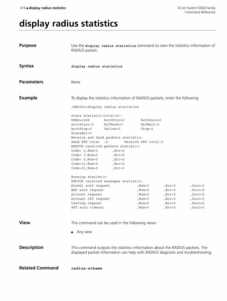
416 ● display radius statistics 3Com Switch 5500 Family Command Reference
display radius statistics
Purpose Use the display radius statistics command to view the statistics information of RADIUS packet.
Syntax display radius statistics
Parameters None
Example To display the statistics information of RADIUS packets, enter the following:
<SW5500>display radius statistics
state statistic(total=0):DEAD=1048 AuthProc=0 AuthSucc=0AcctStart=0 RLTSend=0 RLTWait=0AcctStop=0 OnLine=0 Stop=0StateErr=0Receive and Send packets statistic:Send PKT total :0 Receive PKT total:0RADIUS received packets statistic:Code= 2,Num=0 ,Err=0Code= 3,Num=0 ,Err=0Code= 5,Num=0 ,Err=0Code=11,Num=0 ,Err=0Code=22,Num=0 ,Err=0
Running statistic:RADIUS received messages statistic:Normal auth request ,Num=0 ,Err=0 ,Succ=0EAP auth request ,Num=0 ,Err=0 ,Succ=0Account request ,Num=0 ,Err=0 ,Succ=0Account off request ,Num=0 ,Err=0 ,Succ=0Leaving request ,Num=0 ,Err=0 ,Succ=0PKT auth timeout ,Num=0 ,Err=0 ,Succ=0
View This command can be used in the following views:
■ Any view
Description This command outputs the statistics information about the RADIUS packets. The displayed packet information can help with RADIUS diagnosis and troubleshooting.
Related Command radius-scheme

3Com Switch 5500 Family display remote-ping ● 417 Command Reference
display remote-ping
Purpose Use the display remote-ping command to display the test results.
Syntax display remote-ping { results | history } [ administrator-name test-tag ]
Parameters results Displays the latest test results.
history Displays the test history.
administrator-name Name of the administrator who created the test.
test-tag Test tag.
Example Display the latest test results of the test group administrator icmp.
<S5500> display remote-ping results administrator icmpRemote-ping entry(admin administrator, tag icmp) test result: Destination ip address:10.10.10.10 Send operation times: 10 Receive response times: 10 Min/Max/Average Round Trip Time: 1/2/1 Square-Sum of Round Trip Time: 13 Last complete test time: 2004-11-25 16:28:55.0 Extend result: SD Maximal delay: 0 DS Maximal delay: 0 Packet lost in test: 0% Disconnect operation number:0 Operation timeout number:0 System busy operation number:0 Connection fail number:0 Operation sequence errors:0 Drop operation number:0
Other operation errors:0
Table 71 Description on the fields of the display remote-ping results command
Field Description
Destination ip address Destination IP address
Send operation times Packet sending times
Receive response times Successful packet sending times
Min/Max/Average Round Trip Time
Min/max/average round trip time (RTT)
Square-Sum of Round Trip Time
Quadratic sum of RTTs
Last complete test time Time of the last successful send operation in the test
SD Maximal delay Max delay from the source to the destination
DS Maximal delay Max delay from the destination to the source
Packet lost in test Rate of the lost packets in the test
Disconnect operation number
Number of the disconnect operations forcibly performed by the opposite party
Operation timeout number Number of the send operations getting no response within the timeout time in the test

418 ● display remote-ping 3Com Switch 5500 Family Command Reference
Display the test history of the test group administrator icmp.<S5500> display remote-ping history administrator icmp
Remote-ping entry(admin administrator, tag icmp) history record: Index Response Status LastRC Time 1 1 1 0 2004-11-25 16:28:55.0 2 1 1 0 2004-11-25 16:28:55.0 3 1 1 0 2004-11-25 16:28:55.0 4 1 1 0 2004-11-25 16:28:55.0 5 1 1 0 2004-11-25 16:28:55.0 6 2 1 0 2004-11-25 16:28:55.0 7 1 1 0 2004-11-25 16:28:55.0 8 1 1 0 2004-11-25 16:28:55.0 9 1 1 0 2004-11-25 16:28:55.9 10 1 1 0 2004-11-25 16:28:55.9
View This command can be used in the following views:
■ Any view
System busy operation number
Number of the failed send operations due to system busy in the test
Connection fail number Number of the failed attempts to establish a connection with the opposite party.
Operation sequence errors Number of the out-of-sequence packets received
Drop operation number Number of the failed system resource assignment operations
Other operation errors Number of other errors
Table 72 Description on the fields of the display remote-ping history command
Field Description
Response Round trip time in ms or timeout time. It is 0 if the test fails.
Status Result value of the send operation, including:
1: responseReceived
2: unknown
3: internalError
4: requestTimedOut
5: unknownDestinationAddress
6: noRouteToTarget
7: interfaceInactiveToTarget
8: arpFailure
9: maxConcurrentLimitReached
10: unableToResolveDnsName
11: invalidHostAddress
LastRC Last response code received (this code is based on the specific implementation). When the ICMP Echo function is enabled, if an ICMP response containing ICMP_ECHOREPLY(0) is received, it indicates the detection succeeds.
Time Test time
Table 71 Description on the fields of the display remote-ping results command (continued)
Field Description

3Com Switch 5500 Family display remote-ping ● 419 Command Reference
Description If a test group is specified by using the administrator-name and test-tag arguments, the system displays the test results of the specified test group. Otherwise the system displays the test results of all the test groups.
Related Command ■ remote-ping
■ test-enable
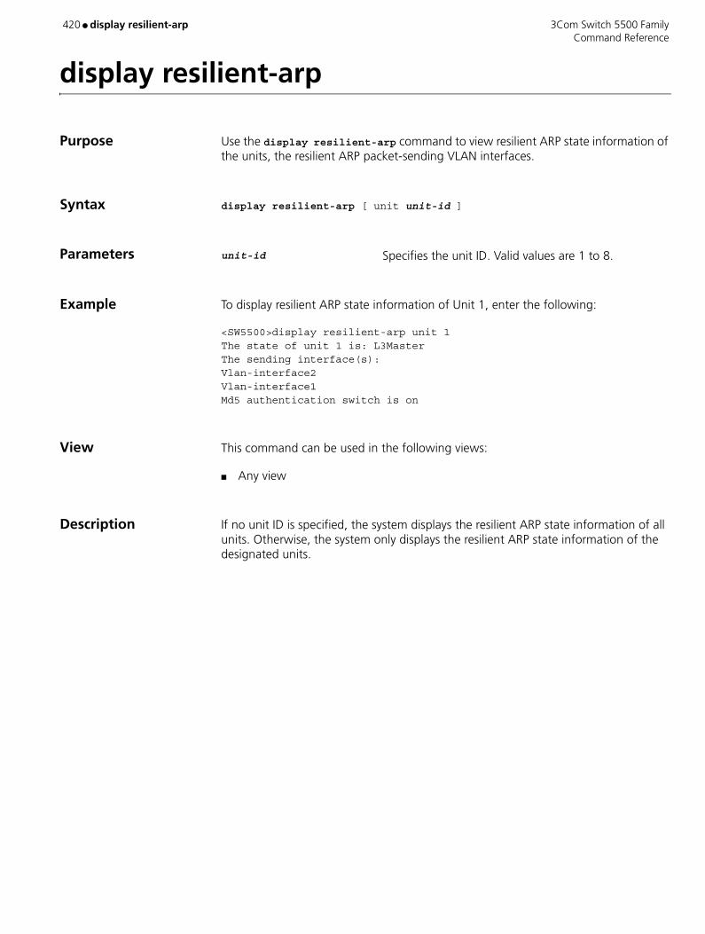
420 ● display resilient-arp 3Com Switch 5500 Family Command Reference
display resilient-arp
Purpose Use the display resilient-arp command to view resilient ARP state information of the units, the resilient ARP packet-sending VLAN interfaces.
Syntax display resilient-arp [ unit unit-id ]
Parameters unit-id Specifies the unit ID. Valid values are 1 to 8.
Example To display resilient ARP state information of Unit 1, enter the following:
<SW5500>display resilient-arp unit 1The state of unit 1 is: L3MasterThe sending interface(s): Vlan-interface2Vlan-interface1Md5 authentication switch is on
View This command can be used in the following views:
■ Any view
Description If no unit ID is specified, the system displays the resilient ARP state information of all units. Otherwise, the system only displays the resilient ARP state information of the designated units.
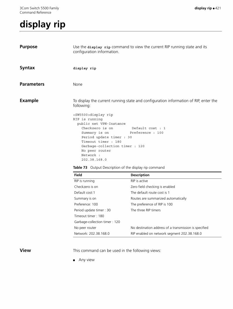
3Com Switch 5500 Family display rip ● 421 Command Reference
display rip
Purpose Use the display rip command to view the current RIP running state and its configuration information.
Syntax display rip
Parameters None
Example To display the current running state and configuration information of RIP, enter the following:
<SW5500>display ripRIP is running public net VPN-Instance Checkzero is on Default cost : 1 Summary is on Preference : 100 Period update timer : 30 Timeout timer : 180 Garbage-collection timer : 120 No peer router Network : 202.38.168.0
View This command can be used in the following views:
■ Any view
Table 73 Output Description of the display rip command
Field Description
RIP is running RIP is active
Checkzero is on Zero field checking is enabled
Default cost:1 The default route cost is 1
Summary is on Routes are summarized automatically
Preference: 100 The preference of RIP is 100
Period update timer : 30
Timeout timer : 180
Garbage-collection timer : 120
The three RIP timers
No peer router No destination address of a transmission is specified
Network: 202.38.168.0 RIP enabled on network segment 202.38.168.0
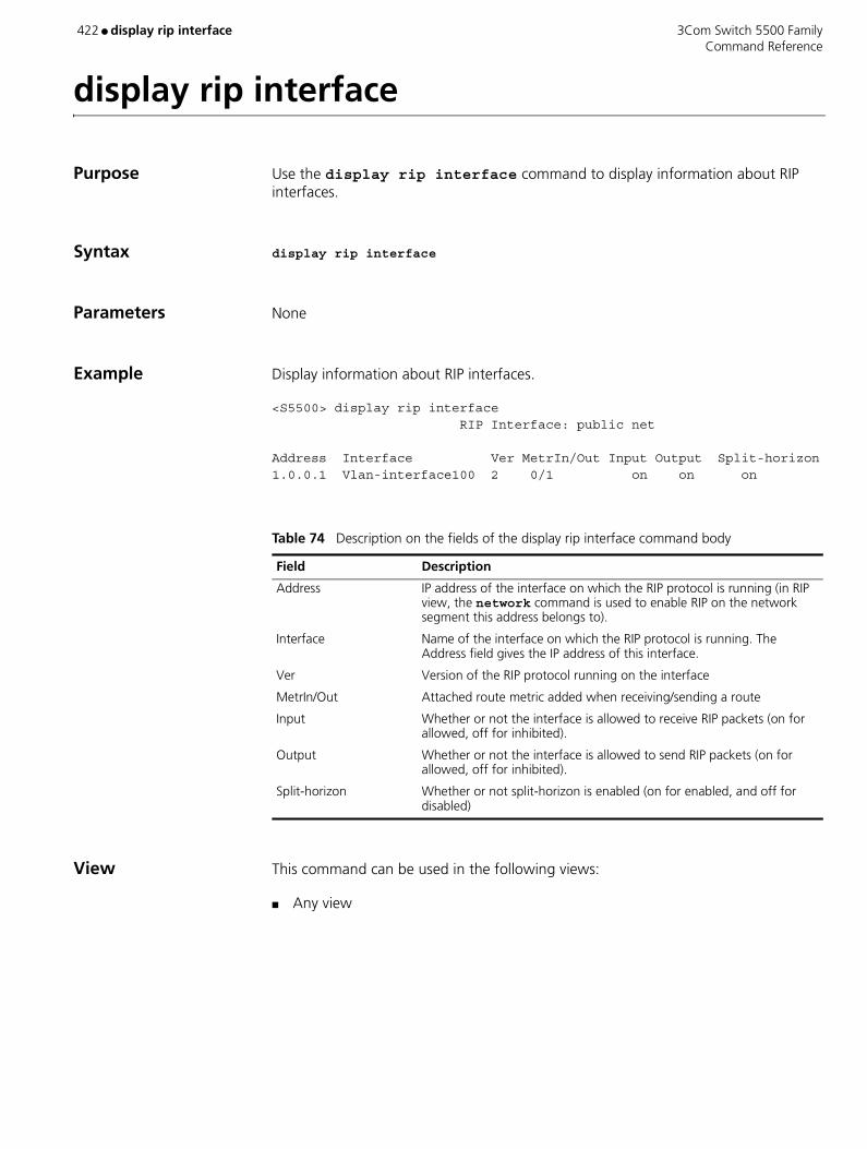
422 ● display rip interface 3Com Switch 5500 Family Command Reference
display rip interface
Purpose Use the display rip interface command to display information about RIP interfaces.
Syntax display rip interface
Parameters None
Example Display information about RIP interfaces.
<S5500> display rip interface RIP Interface: public net
Address Interface Ver MetrIn/Out Input Output Split-horizon1.0.0.1 Vlan-interface100 2 0/1 on on on
View This command can be used in the following views:
■ Any view
Table 74 Description on the fields of the display rip interface command body
Field Description
Address IP address of the interface on which the RIP protocol is running (in RIP view, the network command is used to enable RIP on the network segment this address belongs to).
Interface Name of the interface on which the RIP protocol is running. The Address field gives the IP address of this interface.
Ver Version of the RIP protocol running on the interface
MetrIn/Out Attached route metric added when receiving/sending a route
Input Whether or not the interface is allowed to receive RIP packets (on for allowed, off for inhibited).
Output Whether or not the interface is allowed to send RIP packets (on for allowed, off for inhibited).
Split-horizon Whether or not split-horizon is enabled (on for enabled, and off for disabled)
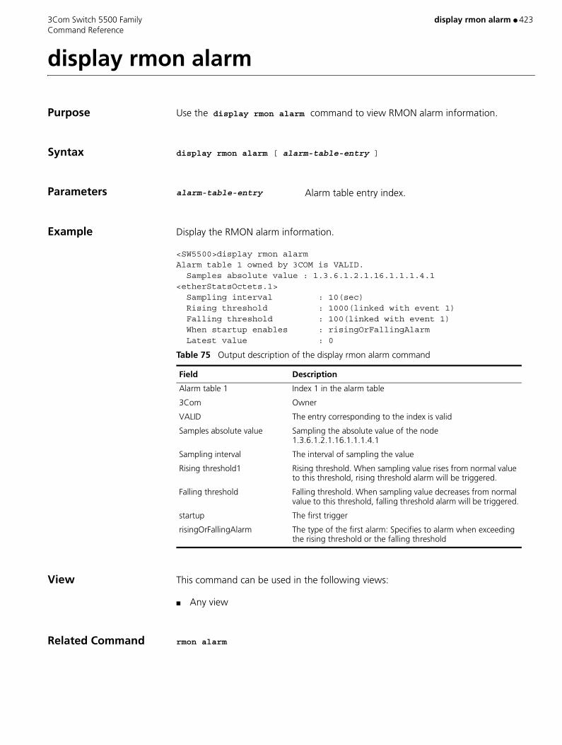
3Com Switch 5500 Family display rmon alarm ● 423 Command Reference
display rmon alarm
Purpose Use the display rmon alarm command to view RMON alarm information.
Syntax display rmon alarm [ alarm-table-entry ]
Parameters alarm-table-entry Alarm table entry index.
Example Display the RMON alarm information.
<SW5500>display rmon alarmAlarm table 1 owned by 3COM is VALID. Samples absolute value : 1.3.6.1.2.1.16.1.1.1.4.1 <etherStatsOctets.1> Sampling interval : 10(sec) Rising threshold : 1000(linked with event 1) Falling threshold : 100(linked with event 1) When startup enables : risingOrFallingAlarm Latest value : 0
View This command can be used in the following views:
■ Any view
Related Command rmon alarm
Table 75 Output description of the display rmon alarm command
Field Description
Alarm table 1 Index 1 in the alarm table
3Com Owner
VALID The entry corresponding to the index is valid
Samples absolute value Sampling the absolute value of the node 1.3.6.1.2.1.16.1.1.1.4.1
Sampling interval The interval of sampling the value
Rising threshold1 Rising threshold. When sampling value rises from normal value to this threshold, rising threshold alarm will be triggered.
Falling threshold Falling threshold. When sampling value decreases from normal value to this threshold, falling threshold alarm will be triggered.
startup The first trigger
risingOrFallingAlarm The type of the first alarm: Specifies to alarm when exceeding the rising threshold or the falling threshold
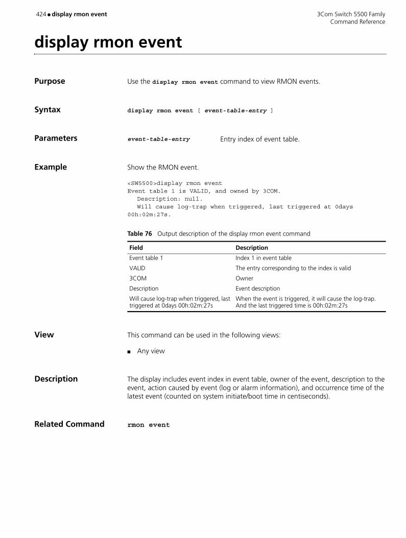
424 ● display rmon event 3Com Switch 5500 Family Command Reference
display rmon event
Purpose Use the display rmon event command to view RMON events.
Syntax display rmon event [ event-table-entry ]
Parameters event-table-entry Entry index of event table.
Example Show the RMON event.
<SW5500>display rmon eventEvent table 1 is VALID, and owned by 3COM.
Description: null.Will cause log-trap when triggered, last triggered at 0days
00h:02m:27s.
View This command can be used in the following views:
■ Any view
Description The display includes event index in event table, owner of the event, description to the event, action caused by event (log or alarm information), and occurrence time of the latest event (counted on system initiate/boot time in centiseconds).
Related Command rmon event
Table 76 Output description of the display rmon event command
Field Description
Event table 1 Index 1 in event table
VALID The entry corresponding to the index is valid
3COM Owner
Description Event description
Will cause log-trap when triggered, last triggered at 0days 00h:02m:27s
When the event is triggered, it will cause the log-trap. And the last triggered time is 00h:02m:27s

3Com Switch 5500 Family display rmon eventlog ● 425 Command Reference
display rmon eventlog
Purpose Use the display rmon eventlog command to display RMON event log.
Syntax display rmon eventlog [ event-number ]
Parameters event-number Entry index of event table.
Example Show the RMON event log.
<SW5500>display rmon eventlog 1Event table 1 owned by 3Com is VALID.Generates eventLog 1.1 at 0days 00h:01m:39s.Description: The 1.3.6.1.2.1.16.1.1.1.4.1 defined in alarm table 1,less than(or =) 100 with alarm value 0. Alarm sample type is absolute.Generates eventLog 1.2 at 0days 00h:02m:27s.Description: The alarm formula defined in private alarm table 1,less than(or =) 100 with alarm value 0. Alarm sample type is absolute.
View This command can be used in the following views:
■ Any view
Description The display includes description about event index in event table, description to the event, and occurrence time of the latest event (counted on system initiate/boot time in centisecond).
Table 77 Output description of the display rmon eventlog command
Field Description
Event table 1 Index 1 in event table
3Com Owner
VALID The entry corresponding to the index is valid
Description Event description
less than (or =) 100 with alarm value 0 The alarm sample value is less than or equal to 100
Alarm sample type is absolute The type of alarm sampling is absolute
Generates eventLog 1.2 at 0days 00h:02m:27s
The eventlog corresponding to the index 1.2 is generated at 0days 00h:02m:27s.
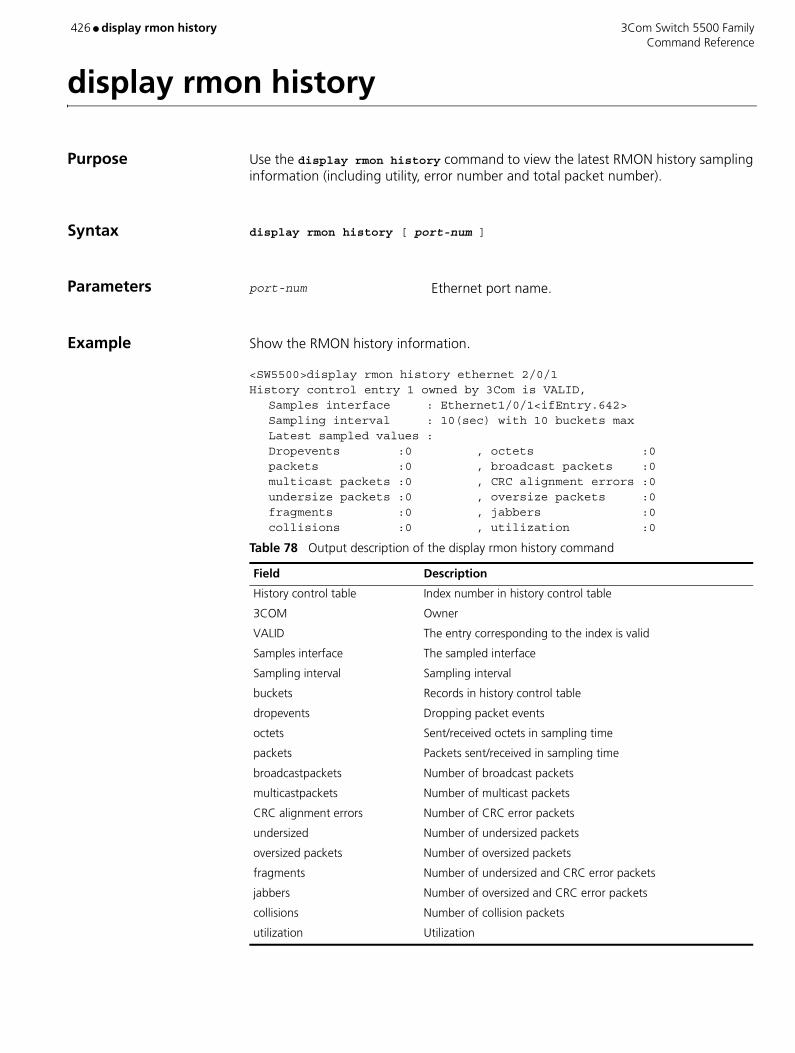
426 ● display rmon history 3Com Switch 5500 Family Command Reference
display rmon history
Purpose Use the display rmon history command to view the latest RMON history sampling information (including utility, error number and total packet number).
Syntax display rmon history [ port-num ]
Parameters port-num Ethernet port name.
Example Show the RMON history information.
<SW5500>display rmon history ethernet 2/0/1History control entry 1 owned by 3Com is VALID,
Samples interface : Ethernet1/0/1<ifEntry.642>Sampling interval : 10(sec) with 10 buckets maxLatest sampled values :Dropevents :0 , octets :0packets :0 , broadcast packets :0multicast packets :0 , CRC alignment errors :0undersize packets :0 , oversize packets :0fragments :0 , jabbers :0collisions :0 , utilization :0
Table 78 Output description of the display rmon history command
Field Description
History control table Index number in history control table
3COM Owner
VALID The entry corresponding to the index is valid
Samples interface The sampled interface
Sampling interval Sampling interval
buckets Records in history control table
dropevents Dropping packet events
octets Sent/received octets in sampling time
packets Packets sent/received in sampling time
broadcastpackets Number of broadcast packets
multicastpackets Number of multicast packets
CRC alignment errors Number of CRC error packets
undersized Number of undersized packets
oversized packets Number of oversized packets
fragments Number of undersized and CRC error packets
jabbers Number of oversized and CRC error packets
collisions Number of collision packets
utilization Utilization

3Com Switch 5500 Family display rmon history ● 427 Command Reference
View This command can be used in the following views:
■ Any view
Related Command rmon history
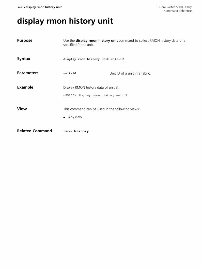
428 ● display rmon history unit 3Com Switch 5500 Family Command Reference
display rmon history unit
Purpose Use the display rmon history unit command to collect RMON history data of a specified fabric unit.
Syntax display rmon history unit unit-id
Parameters unit-id Unit ID of a unit in a fabric.
Example Display RMON history data of unit 3.
<S5500> display rmon history unit 3
View This command can be used in the following views:
■ Any view
Related Command rmon history
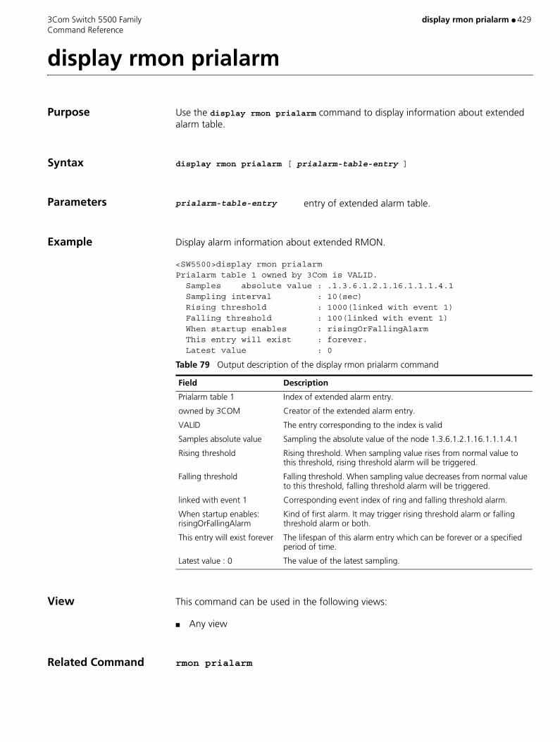
3Com Switch 5500 Family display rmon prialarm ● 429 Command Reference
display rmon prialarm
Purpose Use the display rmon prialarm command to display information about extended alarm table.
Syntax display rmon prialarm [ prialarm-table-entry ]
Parameters prialarm-table-entry entry of extended alarm table.
Example Display alarm information about extended RMON.
<SW5500>display rmon prialarmPrialarm table 1 owned by 3Com is VALID. Samples absolute value : .1.3.6.1.2.1.16.1.1.1.4.1 Sampling interval : 10(sec) Rising threshold : 1000(linked with event 1) Falling threshold : 100(linked with event 1) When startup enables : risingOrFallingAlarm This entry will exist : forever. Latest value : 0
View This command can be used in the following views:
■ Any view
Related Command rmon prialarm
Table 79 Output description of the display rmon prialarm command
Field Description
Prialarm table 1 Index of extended alarm entry.
owned by 3COM Creator of the extended alarm entry.
VALID The entry corresponding to the index is valid
Samples absolute value Sampling the absolute value of the node 1.3.6.1.2.1.16.1.1.1.4.1
Rising threshold Rising threshold. When sampling value rises from normal value to this threshold, rising threshold alarm will be triggered.
Falling threshold Falling threshold. When sampling value decreases from normal value to this threshold, falling threshold alarm will be triggered.
linked with event 1 Corresponding event index of ring and falling threshold alarm.
When startup enables: risingOrFallingAlarm
Kind of first alarm. It may trigger rising threshold alarm or falling threshold alarm or both.
This entry will exist forever The lifespan of this alarm entry which can be forever or a specified period of time.
Latest value : 0 The value of the latest sampling.
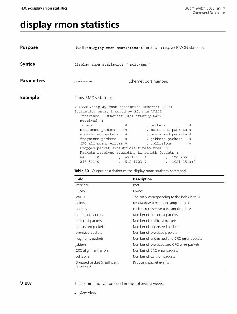
430 ● display rmon statistics 3Com Switch 5500 Family Command Reference
display rmon statistics
Purpose Use the display rmon statistics command to display RMON statistics.
Syntax display rmon statistics [ port-num ]
Parameters port-num Ethernet port number.
Example Show RMON statistics.
<SW5500>display rmon statistics Ethernet 1/0/1Statistics entry 1 owned by 3Com is VALID.
Interface : Ethernet1/0/1<ifEntry.642>Received :octets :0 , packets :0broadcast packets :0 , multicast packets:0undersized packets :0 , oversized packets:0fragments packets :0 , jabbers packets :0CRC alignment errors:0 , collisions :0Dropped packet (insufficient resources):0Packets received according to length (octets):64 :0 , 65-127 :0 , 128-255 :0256-511:0 , 512-1023:0 , 1024-1518:0
View This command can be used in the following views:
■ Any view
Table 80 Output description of the display rmon statistics command
Field Description
Interface Port
3Com Owner
VALID The entry corresponding to the index is valid
octets Received/Sent octets in sampling time
packets Packets received/sent in sampling time
broadcast packets Number of broadcast packets
multicast packets Number of multicast packets
undersized packets Number of undersized packets
oversized packets Number of oversized packets
fragments packets Number of undersized and CRC error packets
jabbers Number of oversized and CRC error packets
CRC alignment errors Number of CRC error packets
collisions Number of collision packets
Dropped packet (insufficient resources)
Dropping packet events

3Com Switch 5500 Family display rmon statistics ● 431 Command Reference
Description The displayed information includes collision, CRC (Cyclic Redundancy Check) and queue, undersized or oversized packet, timeout, fragment, broadcast, multicast, unicast, and bandwidth utility.
Related Command rmon statistics
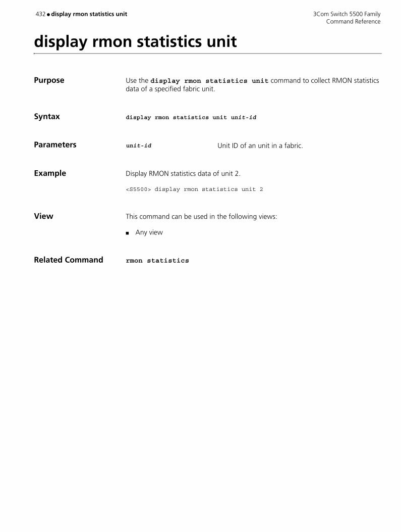
432 ● display rmon statistics unit 3Com Switch 5500 Family Command Reference
display rmon statistics unit
Purpose Use the display rmon statistics unit command to collect RMON statistics data of a specified fabric unit.
Syntax display rmon statistics unit unit-id
Parameters unit-id Unit ID of an unit in a fabric.
Example Display RMON statistics data of unit 2.
<S5500> display rmon statistics unit 2
View This command can be used in the following views:
■ Any view
Related Command rmon statistics
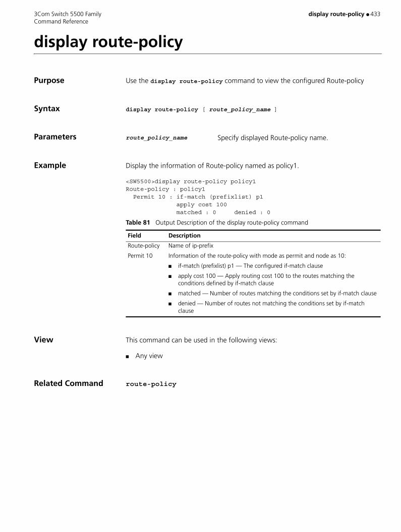
3Com Switch 5500 Family display route-policy ● 433 Command Reference
display route-policy
Purpose Use the display route-policy command to view the configured Route-policy
Syntax display route-policy [ route_policy_name ]
Parameters route_policy_name Specify displayed Route-policy name.
Example Display the information of Route-policy named as policy1.
<SW5500>display route-policy policy1Route-policy : policy1 Permit 10 : if-match (prefixlist) p1 apply cost 100 matched : 0 denied : 0
View This command can be used in the following views:
■ Any view
Related Command route-policy
Table 81 Output Description of the display route-policy command
Field Description
Route-policy Name of ip-prefix
Permit 10 Information of the route-policy with mode as permit and node as 10:
■ if-match (prefixlist) p1 — The configured if-match clause
■ apply cost 100 — Apply routing cost 100 to the routes matching the conditions defined by if-match clause
■ matched — Number of routes matching the conditions set by if-match clause
■ denied — Number of routes not matching the conditions set by if-match clause
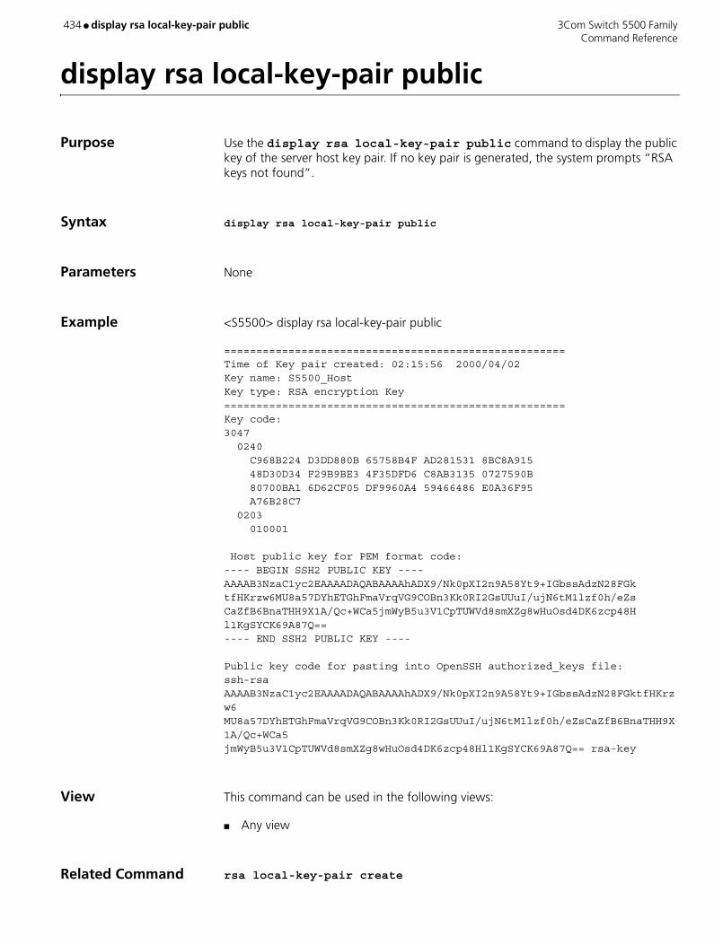
434 ● display rsa local-key-pair public 3Com Switch 5500 Family Command Reference
display rsa local-key-pair public
Purpose Use the display rsa local-key-pair public command to display the public key of the server host key pair. If no key pair is generated, the system prompts “RSA keys not found”.
Syntax display rsa local-key-pair public
Parameters None
Example <S5500> display rsa local-key-pair public
=====================================================Time of Key pair created: 02:15:56 2000/04/02Key name: S5500_HostKey type: RSA encryption Key=====================================================Key code:3047 0240 C968B224 D3DD880B 65758B4F AD281531 8BC8A915 48D30D34 F29B9BE3 4F35DFD6 C8AB3135 0727590B 80700BA1 6D62CF05 DF9960A4 59466486 E0A36F95 A76B28C7 0203 010001
Host public key for PEM format code:---- BEGIN SSH2 PUBLIC KEY ---- AAAAB3NzaC1yc2EAAAADAQABAAAAhADX9/Nk0pXI2n9A58Yt9+IGbssAdzN28FGktfHKrzw6MU8a57DYhETGhFmaVrqVG9COBn3Kk0RI2GsUUuI/ujN6tM1lzf0h/eZsCaZfB6BnaTHH9X1A/Qc+WCa5jmWyB5u3V1CpTUWVd8smXZg8wHuOsd4DK6zcp48Hl1KgSYCK69A87Q==---- END SSH2 PUBLIC KEY ----
Public key code for pasting into OpenSSH authorized_keys file:ssh-rsa AAAAB3NzaC1yc2EAAAADAQABAAAAhADX9/Nk0pXI2n9A58Yt9+IGbssAdzN28FGktfHKrzw6MU8a57DYhETGhFmaVrqVG9COBn3Kk0RI2GsUUuI/ujN6tM1lzf0h/eZsCaZfB6BnaTHH9X1A/Qc+WCa5 jmWyB5u3V1CpTUWVd8smXZg8wHuOsd4DK6zcp48Hl1KgSYCK69A87Q== rsa-key
View This command can be used in the following views:
■ Any view
Related Command rsa local-key-pair create
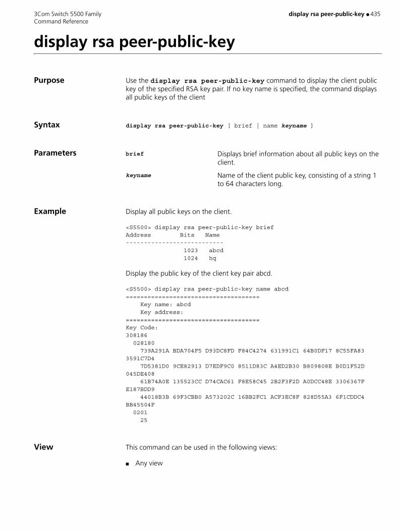
3Com Switch 5500 Family display rsa peer-public-key ● 435 Command Reference
display rsa peer-public-key
Purpose Use the display rsa peer-public-key command to display the client public key of the specified RSA key pair. If no key name is specified, the command displays all public keys of the client
Syntax display rsa peer-public-key [ brief | name keyname ]
Parameters brief Displays brief information about all public keys on the client.
keyname Name of the client public key, consisting of a string 1 to 64 characters long.
Example Display all public keys on the client.
<S5500> display rsa peer-public-key briefAddress Bits Name--------------------------- 1023 abcd 1024 hq
Display the public key of the client key pair abcd.
<S5500> display rsa peer-public-key name abcd===================================== Key name: abcd Key address:=====================================Key Code:308186 028180 739A291A BDA704F5 D93DC8FD F84C4274 631991C1 64B0DF17 8C55FA83 3591C7D4 7D5381D0 9CE82913 D7EDF9C0 8511D83C A4ED2B30 B809808E B0D1F52D 045DE408 61B74A0E 135523CC D74CAC61 F8E58C45 2B2F3F2D A0DCC48E 3306367F E187BDD9 44018B3B 69F3CBB0 A573202C 16BB2FC1 ACF3EC8F 828D55A3 6F1CDDC4 BB45504F 0201 25
View This command can be used in the following views:
■ Any view

436 ● display saved-configuration 3Com Switch 5500 Family Command Reference
display saved-configuration
Purpose Use the display saved-configuration command to display the current configuration file in the flash memory of an Ethernet switch.
Syntax display saved-configuration [ unit unit-id ] [ by-linenum ]
Parameters unit unit-id Specifies the unit ID of a switch.
by-linenum Displays the number of each line.
Example Display the current configuration file in the flash memory, and display the number of each line.
<S5500> display saved-configuration by-linenum 1: # 2: sysname 5600-EI 3: # 4: mirroring-group 2 local 5: # 6: radius scheme system 7: # 8: domain system 9: # 10: vlan 1 11: # 12: vlan 3 13: # 14: interface Vlan-interface1 15: #LOCCFG. MUST NOT DELETE 16: # 17: interface Aux1/0/0 18: # 19: interface GigabitEthernet1/0/1 20: # 21: interface GigabitEthernet1/0/2 22: # 23: interface GigabitEthernet1/0/3 24: mirroring-group 2 mirroring-port inbound 25: # 26: interface GigabitEthernet1/0/4 27: mirroring-group 2 mirroring-port inbound 28: # 29: interface GigabitEthernet1/0/5 30: mirroring-group 2 mirroring-port inbound 31: # 32: interface GigabitEthernet1/0/6 33: mirroring-group 2 monitor-port 34: # 35: interface GigabitEthernet1/0/7 36: # 37: interface GigabitEthernet1/0/8 38: # 39: interface GigabitEthernet1/0/9

3Com Switch 5500 Family display saved-configuration ● 437 Command Reference
40: # 41: interface GigabitEthernet1/0/10 42: # 43: interface GigabitEthernet1/0/11 44: # 45: interface GigabitEthernet1/0/12 46: # 47: interface GigabitEthernet1/0/13 48: # 49: interface GigabitEthernet1/0/14 50: # 51: interface GigabitEthernet1/0/15 52: # 53: interface GigabitEthernet1/0/16 54: # 55: interface GigabitEthernet1/0/17 56: # 57: interface GigabitEthernet1/0/18 58: # 59: interface GigabitEthernet1/0/19 60: # 61: interface GigabitEthernet1/0/20 62: # 63: interface GigabitEthernet1/0/21 64: # 65: interface GigabitEthernet1/0/22 66: # 67: interface GigabitEthernet1/0/23 68: # 69: interface GigabitEthernet1/0/24 70: # 71: #TOPOLOGYCFG. MUST NOT DELETE 72: # 73: undo irf-fabric authentication-mode 74: #GLBCFG. MUST NOT DELETE 75: # 76: interface NULL0 77: # 78: cluster 79: ip-pool 10.100.10.1 255.255.255.0 80: # 81: snmp-agent 82: snmp-agent local-engineid 800007DB0012A99022406877 83: snmp-agent sys-info version all 84: # 85: undo cluster enable 86: # 87: user-interface aux 0 7 88: user-interface vty 0 4 89: # 90: return
The above configurations are listed in the following order: global, port, and user interface configurations.
View This command can be used in the following views:
■ Any view

438 ● display saved-configuration 3Com Switch 5500 Family Command Reference
Description If an Ethernet switch does not work normally after it is powered on, you can use the display saved-configuration command to view the startup configurations of the Ethernet switch.

3Com Switch 5500 Family display schedule reboot ● 439 Command Reference
display schedule reboot
Purpose Use the display schedule reboot command to check the configuration of related parameters of the switch schedule reboot terminal service.
Syntax display schedule reboot
Parameters None
Example Display the configuration of the schedule reboot terminal service parameters of the current switch.
<SW5500>display schedule rebootSystem will reboot at 03:41 2000/04/02 (in 1 hours and 27 minutes).
View This command can be used in the following views:
■ Any view
Related Commands ■ reboot
■ schedule reboot at
■ schedule reboot delay
■ undo schedule reboot

440 ● display sftp source-ip 3Com Switch 5500 Family Command Reference
display sftp source-ip
Purpose Use the display sftp source-ip command to display the source IP address of the SFTP client. If no source IP address is specified, 0.0.0.0 is displayed.
Syntax display sftp source-ip
Parameters None
Example Display the source IP address of the SFTP client.
<S5500> display sftp source-ipThe source IP you specified is 192.168.1.1
View This command can be used in the following views:
■ Any view
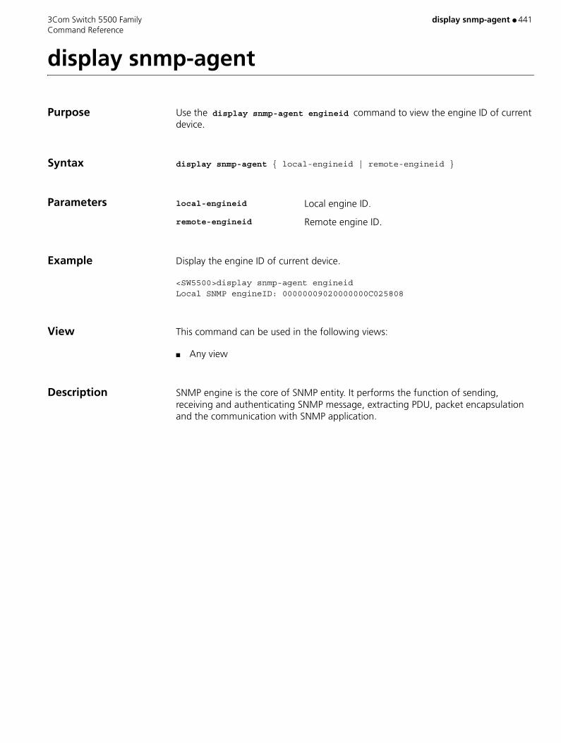
3Com Switch 5500 Family display snmp-agent ● 441 Command Reference
display snmp-agent
Purpose Use the display snmp-agent engineid command to view the engine ID of current device.
Syntax display snmp-agent { local-engineid | remote-engineid }
Parameters local-engineid Local engine ID.
remote-engineid Remote engine ID.
Example Display the engine ID of current device.
<SW5500>display snmp-agent engineidLocal SNMP engineID: 00000009020000000C025808
View This command can be used in the following views:
■ Any view
Description SNMP engine is the core of SNMP entity. It performs the function of sending, receiving and authenticating SNMP message, extracting PDU, packet encapsulation and the communication with SNMP application.
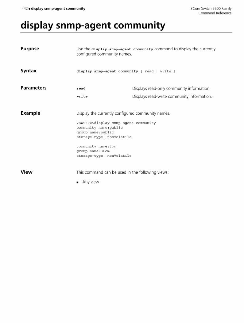
442 ● display snmp-agent community 3Com Switch 5500 Family Command Reference
display snmp-agent community
Purpose Use the display snmp-agent community command to display the currently configured community names.
Syntax display snmp-agent community [ read | write ]
Parameters read Displays read-only community information.
write Displays read-write community information.
Example Display the currently configured community names.
<SW5500>display snmp-agent communitycommunity name:publicgroup name:publicstorage-type: nonVolatile
community name:tomgroup name:3Comstorage-type: nonVolatile
View This command can be used in the following views:
■ Any view

3Com Switch 5500 Family display snmp-agent group ● 443 Command Reference
display snmp-agent group
Purpose Use the display snmp-agent group command to display group name, safe mode, state of various views and storage modes.
Syntax display snmp-agent group [ group-name ]
Parameters groupname Group name. Valid values are 1 to 32 bytes.
Example Display SNMP group name and safe mode.
<SW5500>display snmp-agent groupgroupname: publicSecurity model: v2c noAuthnoPrivreadview:v1defaultwriteview: no writeview specified notifyview: *tv.FFFFFFFFstorage-type: volatile
The following table describes the output fields.
View This command can be used in the following views:
■ Any view
Table 82 Output description of the display snmp-agent group command
Field Description
groupname SNMP Group name of the user
Security model The security model adopted by SNMP
readview Read-only MIB view name corresponding to that group
writeview Writable MIB view corresponding to that group
notifyview The name of the notify MIB view corresponding to that group
storage-type Storage type
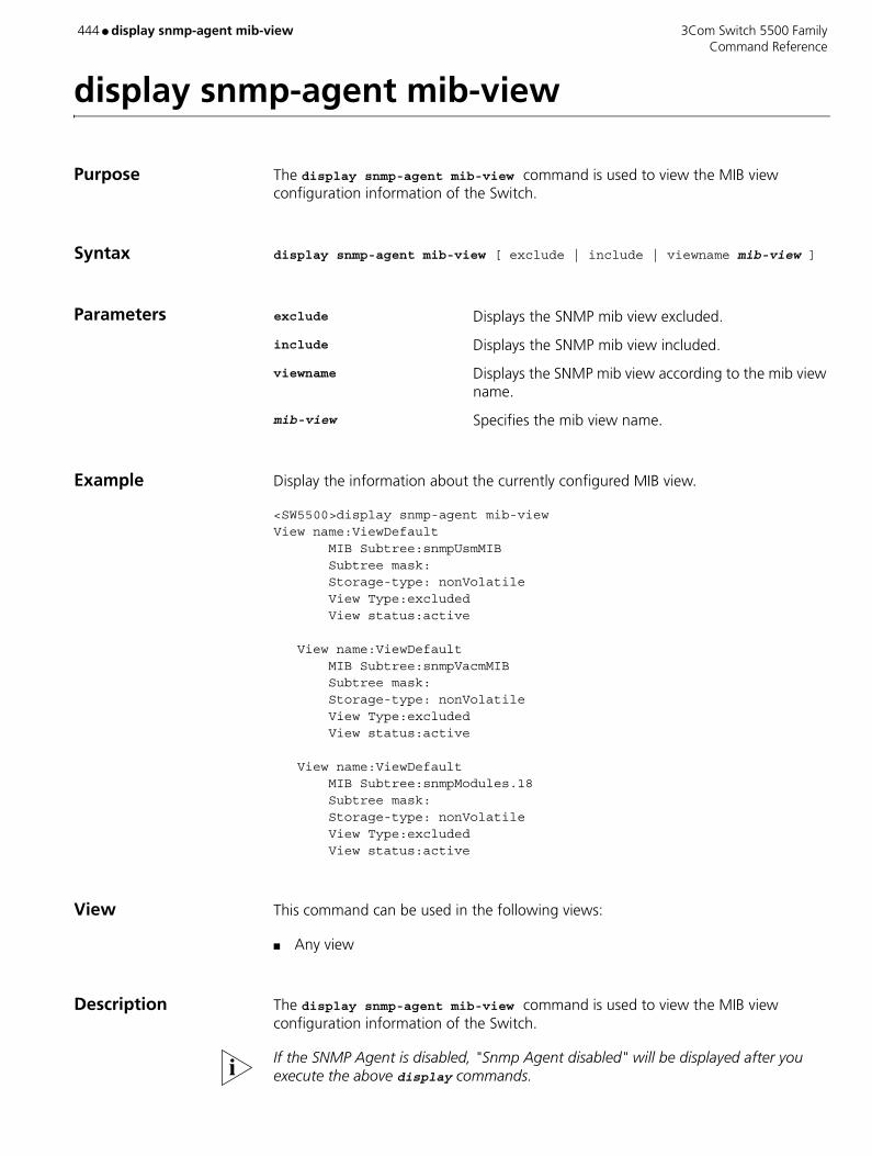
444 ● display snmp-agent mib-view 3Com Switch 5500 Family Command Reference
display snmp-agent mib-view
Purpose The display snmp-agent mib-view command is used to view the MIB view configuration information of the Switch.
Syntax display snmp-agent mib-view [ exclude | include | viewname mib-view ]
Parameters exclude Displays the SNMP mib view excluded.
include Displays the SNMP mib view included.
viewname Displays the SNMP mib view according to the mib view name.
mib-view Specifies the mib view name.
Example Display the information about the currently configured MIB view.
<SW5500>display snmp-agent mib-viewView name:ViewDefault MIB Subtree:snmpUsmMIB Subtree mask: Storage-type: nonVolatile View Type:excluded View status:active
View name:ViewDefault MIB Subtree:snmpVacmMIB Subtree mask: Storage-type: nonVolatile View Type:excluded View status:active
View name:ViewDefault MIB Subtree:snmpModules.18 Subtree mask: Storage-type: nonVolatile View Type:excluded View status:active
View This command can be used in the following views:
■ Any view
Description The display snmp-agent mib-view command is used to view the MIB view configuration information of the Switch.
If the SNMP Agent is disabled, "Snmp Agent disabled" will be displayed after you execute the above display commands.

3Com Switch 5500 Family display snmp-agent statistics ● 445 Command Reference
display snmp-agent statistics
Purpose Use the display snmp-agent statistics command to view the current state of SNMP communication.
Syntax display snmp-agent statistics
Parameters None
Example Display the current state of SNMP communication.
<SW5500>display snmp-agent statistics0 Messages delivered to the SNMP entity0 Messages which were for an unsupported version0 Messages which used an unknown community name0 Messages which represented an illegal operation for the community supplied0 ASN.1 or BER errors in the process of decoding0 MIB objects retrieved successfully0 MIB objects altered successfully0 Get-request PDUs accepted and processed0 Get-next PDUs accepted and processed0 Set-request PDUs accepted and processed3 Messages passed from the SNMP entity0 SNMP PDUs which had a tooBig error (Maximum packet size 1500)0 SNMP PDUs which had a noSuchName error0 SNMP PDUs which had a badValue error0 SNMP PDUs which had a general error0 Response PDUs accepted and processed3 Trap PDUs accepted and processed
The following table describes the output fields.
Table 83 Output description of the display snmp-agent statistics command
Field Description
0 Messages delivered to the SNMP entity Total number of the input SNMP packets
0 Messages which were for an unsupported version
Number of packets with version information error
0 Messages which used an unknown community name
Number of packets with community name error
0 Messages which represented an illegal operation for the community supplied
Number of packets with authority error corresponding to the community name
0 ASN.1 or BER errors in the process of decoding
Number of SNMP packets with encoding error
0 MIB objects retrieved successfully Number of variables requested by NMS
0 MIB objects altered successfully The number of variables set by NMS
0 Get-request PDUs accepted and processed
Number of the received packets requested by get
0 Get-next PDUs accepted and processed Number of the received packets requested by get-next
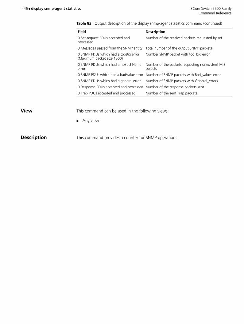
446 ● display snmp-agent statistics 3Com Switch 5500 Family Command Reference
View This command can be used in the following views:
■ Any view
Description This command provides a counter for SNMP operations.
0 Set-request PDUs accepted and processed
Number of the received packets requested by set
3 Messages passed from the SNMP entity Total number of the output SNMP packets
0 SNMP PDUs which had a tooBig error (Maximum packet size 1500)
Number SNMP packet with too_big error
0 SNMP PDUs which had a noSuchName error
Number of the packets requesting nonexistent MIB objects
0 SNMP PDUs which had a badValue error Number of SNMP packets with Bad_values error
0 SNMP PDUs which had a general error Number of SNMP packets with General_errors
0 Response PDUs accepted and processed Number of the response packets sent
3 Trap PDUs accepted and processed Number of the sent Trap packets
Table 83 Output description of the display snmp-agent statistics command (continued)
Field Description

3Com Switch 5500 Family display snmp-agent sys-info ● 447 Command Reference
display snmp-agent sys-info
Purpose Use the display snmp-agent sys-info command to view the system information of SNMP configuration.
Syntax display snmp-agent sys-info [ contact | location | version ]*
Parameters None
Example Display the character string sysContact (system contact).
<SW5500>display snmp-agent sys-info contactThe contact person for this managed node:Mr.Smith -Tel:3306
Display the system location.
<SW5500>display snmp-agent sys-info locationThe physical location of this node:Boston USA
Display the version information of running SNMP
<SW5500>display snmp-agent sys-info versionSNMP version running in the system:SNMPv3
View This command can be used in the following views:
■ Any view
Description The information includes the character string sysContact (system contact), the character string describing the system location, the version information about the running SNMP in the system.

448 ● display snmp-agent trap-list 3Com Switch 5500 Family Command Reference
display snmp-agent trap-list
Purpose Use the display snmp-agent trap-list command to display trap list information.
Syntax display snmp-agent trap-list
Parameters None
Example Display the trap list information.
<S5500> display snmp-agent trap-list configuration trap enable flash trap enable ospf trap enable standard trap enable system trap enable vrrp trap enable
Enable traps :6; Disable traps 0
View This command can be used in the following views:
■ Any view
Related Command snmp-agent trap enable

3Com Switch 5500 Family display snmp-agent usm-user ● 449 Command Reference
display snmp-agent usm-user
Purpose Use the display snmp-agent usm-user command to view information of all the SNMP usernames in the group username list.
Syntax display snmp-agent usm-user [ engineid engineid | group groupname | username username ]
Parameters engineid Displays user information with specified engine ID.
username Displays user information with specified user name.
groupname Displays user information of specified group.
Example Display the information of all the current users.
<SW5500>display snmp-agent usm-userUser name: hello Group name: hellogroup Engine ID: 800007DB00E0FC0055006877 Storage-type: nonVolatile UserStatus: active Acl:2000
View This command can be used in the following views:
■ Any view

450 ● display snmp-proxy unit 3Com Switch 5500 Family Command Reference
display snmp-proxy unit
Purpose Using display snmp-proxy unit command, you can view statistics information of SNMP proxy.
Syntax display snmp-proxy unit unit-id
Parameters unit-id Unit ID of the switch.
Example View statistics information of SNMP proxy on unit 1.
<SW5500> display snmp-proxy unit 1Number of GetReq msgs received :0Number of GetReq msgs sent :0
Number of GetNextReq msgs Received :0Number of GetNextReq msgs sent :0
Number of GetResp msgs received :0Number of GetResp msgs sent :0
Number of GetNextResp msgs received :0Number of GetNextResp msgs sent :0
Number of SnmpMibSync msgs received :0Number of SnmpMibSync msgs sent :0
Number of SnmpMibGetCntrReq msgs received :0Number of SnmpMibGetCntrReq msgs sent :0
Number of SnmpMibGetCntrResp msgs received :0Number of SnmpMibGetCntrResp msgs sent :0
View This command can be used in the following views:
■ Any view
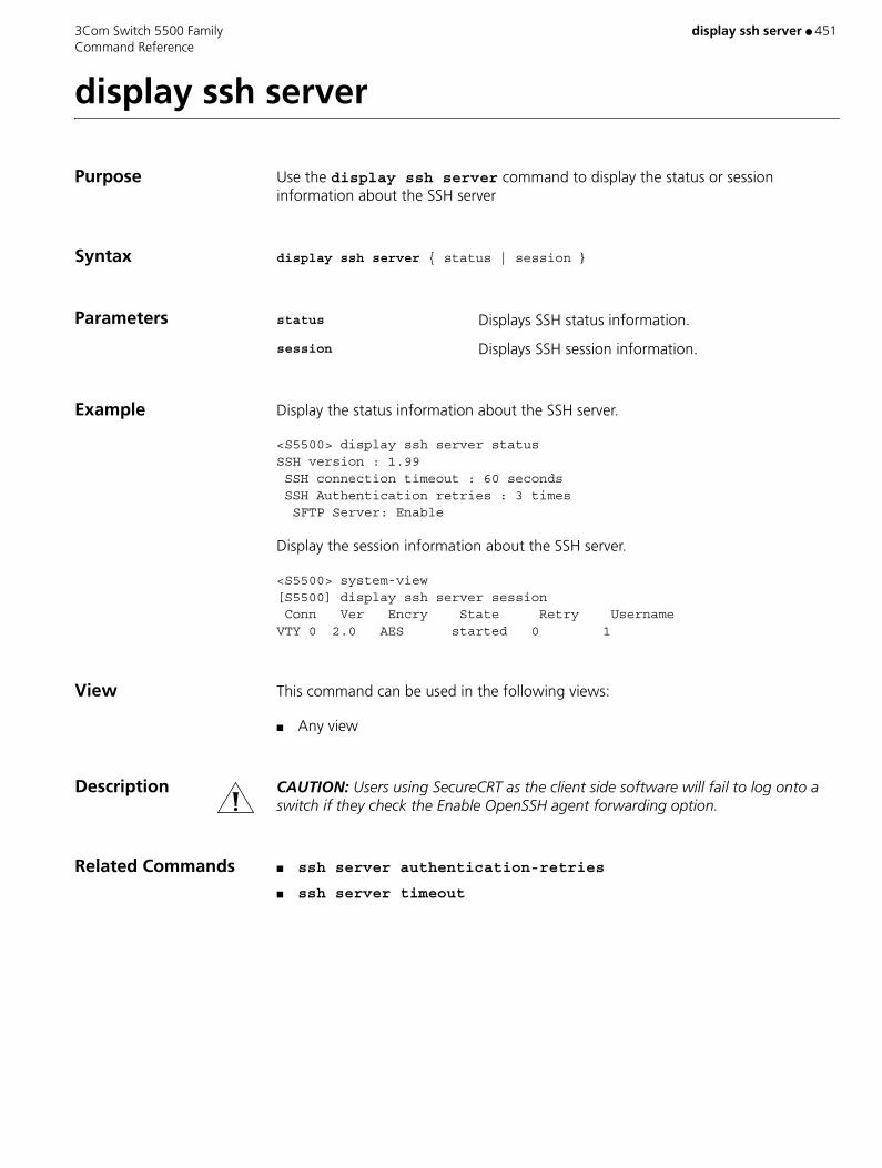
3Com Switch 5500 Family display ssh server ● 451 Command Reference
display ssh server
Purpose Use the display ssh server command to display the status or session information about the SSH server
Syntax display ssh server { status | session }
Parameters status Displays SSH status information.
session Displays SSH session information.
Example Display the status information about the SSH server.
<S5500> display ssh server statusSSH version : 1.99 SSH connection timeout : 60 seconds SSH Authentication retries : 3 times SFTP Server: Enable
Display the session information about the SSH server.
<S5500> system-view[S5500] display ssh server session Conn Ver Encry State Retry UsernameVTY 0 2.0 AES started 0 1
View This command can be used in the following views:
■ Any view
Description CAUTION: Users using SecureCRT as the client side software will fail to log onto a switch if they check the Enable OpenSSH agent forwarding option.
Related Commands ■ ssh server authentication-retries
■ ssh server timeout

452 ● display ssh server-info 3Com Switch 5500 Family Command Reference
display ssh server-info
Purpose Use the display ssh server-info command to display the association between the server public keys configured on the client and the servers.
Syntax display ssh server-info
Parameters None
Example Display the association between the server public keys and the servers.
[S5500] display ssh server-infoServer Name(IP) Server public key name______________________________________________________192.168.0.1 abc_key01192.168.0.2 abc_key02
View This command can be used in the following views:
■ Any view
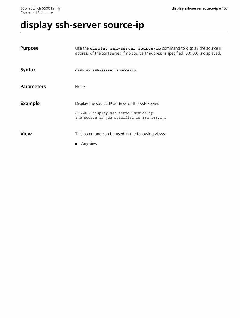
3Com Switch 5500 Family display ssh-server source-ip ● 453 Command Reference
display ssh-server source-ip
Purpose Use the display ssh-server source-ip command to display the source IP address of the SSH server. If no source IP address is specified, 0.0.0.0 is displayed.
Syntax display ssh-server source-ip
Parameters None
Example Display the source IP address of the SSH server.
<S5500> display ssh-server source-ipThe source IP you specified is 192.168.1.1
View This command can be used in the following views:
■ Any view
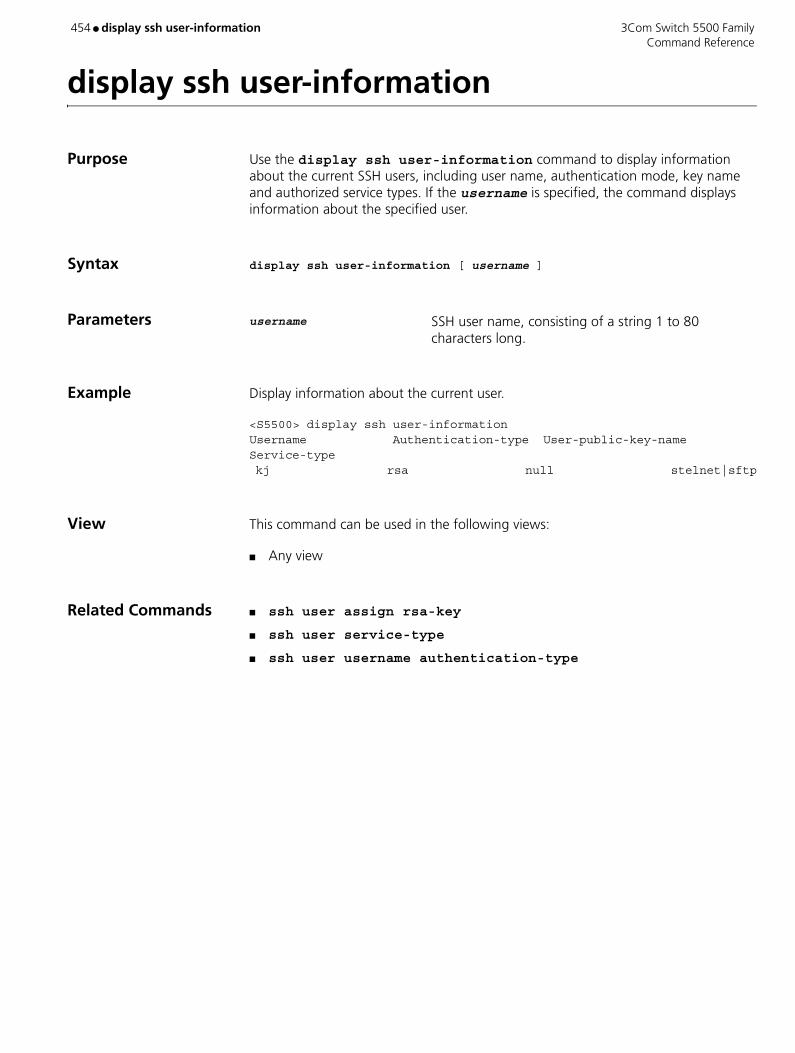
454 ● display ssh user-information 3Com Switch 5500 Family Command Reference
display ssh user-information
Purpose Use the display ssh user-information command to display information about the current SSH users, including user name, authentication mode, key name and authorized service types. If the username is specified, the command displays information about the specified user.
Syntax display ssh user-information [ username ]
Parameters username SSH user name, consisting of a string 1 to 80 characters long.
Example Display information about the current user.
<S5500> display ssh user-informationUsername Authentication-type User-public-key-name Service-type kj rsa null stelnet|sftp
View This command can be used in the following views:
■ Any view
Related Commands ■ ssh user assign rsa-key
■ ssh user service-type
■ ssh user username authentication-type
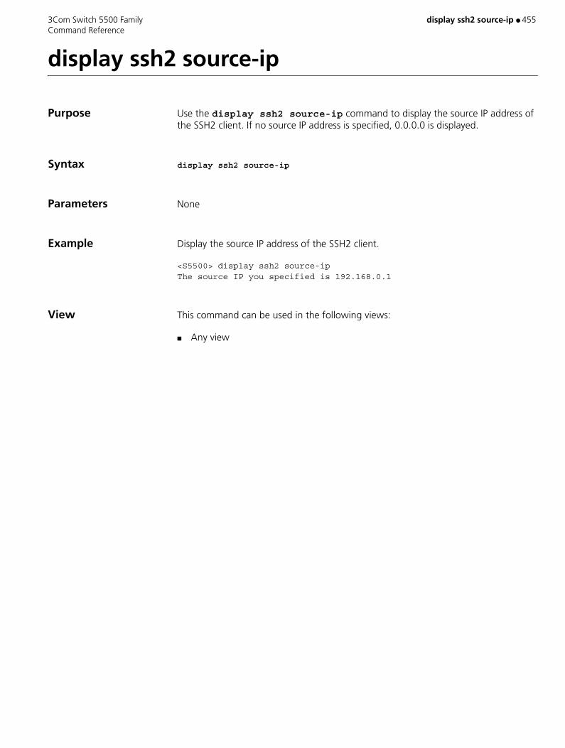
3Com Switch 5500 Family display ssh2 source-ip ● 455 Command Reference
display ssh2 source-ip
Purpose Use the display ssh2 source-ip command to display the source IP address of the SSH2 client. If no source IP address is specified, 0.0.0.0 is displayed.
Syntax display ssh2 source-ip
Parameters None
Example Display the source IP address of the SSH2 client.
<S5500> display ssh2 source-ipThe source IP you specified is 192.168.0.1
View This command can be used in the following views:
■ Any view

456 ● display startup 3Com Switch 5500 Family Command Reference
display startup
Purpose Use the display startup command to display the information about the startup configuration files on one switch or all switches in the fabric, including the names of the currently used, the to-be-used main and backup startup configuration files.
Syntax display startup [ unit unit-id ]
Parameters unit unit-id Unit ID of a switch.
Example Display the information about the startup configuration files on unit 1 in the fabric.
<S5500> display startup unit 1MainBoard: Current Startup saved-configuration file: NULL Next main startup saved-configuration file: flash:/123.cfg Next backup startup saved-configuration file: flash:/back.cfg Bootrom-access enable state: enabled
View This command can be used in the following views:
■ Any view
Description Executing the display startup command without unit unit-id will display the settings in the whole fabric.
Related Command startup saved-configuration

3Com Switch 5500 Family display stop-accounting buffer ● 457 Command Reference
display stop-accounting buffer
Purpose Use the display stop-accounting-buffer command to view information on the stop-accounting requests buffered in the switch.
Syntax display stop-accounting-buffer hwtacacs-scheme hwtacacs-scheme-name
Parameters hwtacacs-scheme hwtacacs-scheme-name: Displays information on buffered stop-accounting
requests related to the HWTACACS scheme specified by hwtacacs-scheme-name. Valid values are a character string not exceeding 32 characters, excluding “?”.
Example Display information on the buffered stop-accounting requests related to the HWTACACS scheme “3Com".
<S5500> display stop-accounting-buffer hwtacacs-scheme 3Com
View This command can be used in the following views:
■ Any view
Related Commands ■ reset stop-accounting-buffer
■ retry stop-accounting
■ stop-accounting-buffer enable

458 ● display stp 3Com Switch 5500 Family Command Reference
display stp
Purpose Use the display stp command to display the status and statistics of specified spanning trees, and hereby analyze and maintain the topology of a network and to make MSTP operate properly.
Syntax display stp [ instance instance-id ] [ interface interface-list | slot slot-number ] [ brief ]
Parameters instance-id ID of the spanning tree instance. Valid values are 0 to 16. A value of 0 specifies the CIST.
interface-list List of Ethernet ports. You can specify multiple Ethernet ports by providing this argument in the form of interface-list = { interface-type interface-number [ to interface-type interface-number ] } &<1-10>, where &<1-10> means that you can provide up to 10 port indexes/port index lists for this argument.
slot slot-number Specifies the slot whose STP information is to be displayed.
brief Displays only port status and protection measures taken for the ports.
Example Display the status of a spanning tree.
<S5500> display stp instance 0 interface Ethernet 1/0/1 to Ethernet 1/0/4 brief MSTID Port Role STP State Protection 0 Ethernet1/0/1 ALTE DISCARDING LOOP 0 Ethernet1/0/2 DESI FORWARDING NONE 0 Ethernet1/0/3 DESI FORWARDING NONE 0 Ethernet1/0/4 DESI FORWARDING NONE
View This command can be used in the following views:
■ Any view
Table 84 Description on the fields of the display stp command
Field Description
MSTID ID of the MSTI in the MST region
Port Port number corresponding to the spanning tree instance
Role Port role
STP State STP state of the port, which can be forwarding or discarding.
Protection Protection type of the port

3Com Switch 5500 Family display stp ● 459 Command Reference
Description The information displayed by this command depends on what parameters you specify:
■ With neither spanning tree instance nor port lists specified: spanning tree information about all spanning tree instances on all ports is displayed by port number.
■ With only the spanning tree instance specified: information about the spanning tree instance on all ports is displayed by port number.
■ With only the port lists specified: information about all spanning tree instances on the specified ports is displayed by port number.
■ With both spanning tree instance and port lists specified: information about the specified spanning tree instance and the specified ports is displayed by spanning tree instance ID.
MSTP status information includes the following:
■ Global CIST parameters: Protocol operation mode, switch priority in the CIST instance, MAC address, Hello time, Max Age, Forward delay, Max hop count, the common root bridge of the CIST, the external path cost for the switch to reach the CIST common root bridge, the region root, the internal path cost for the switch to reach the region root, CIST root port of the switch, and the status of the BPDU protection function (enabled or disabled).
■ CIST port parameters: Port protocol, port role, port priority, path cost, the designated bridge, the designated port, edge port/non-edge port, connected/not connected to a point-to-point link, the maximum transmission speed, the type of the root protection feature, VLAN mappings, Hello time, Max age, Forward delay, Message-age time, and Remaining-hops.
■ Global MSTI parameters: MSTI ID, bridge priority of the instance, region root, internal path cost, MSTI root port, and Master bridge.
■ MSTI port parameters: Port status, role, priority, path cost, the designated bridge, the designated port, and Remaining Hops.
The statistics includes the number of the TCN BPDUs, the configuration BPDUs, the RST BPDUs, and the MST BPDUs transmitted/received by the port.
Related Command reset stp
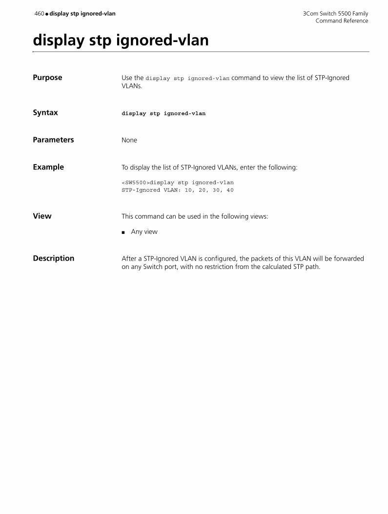
460 ● display stp ignored-vlan 3Com Switch 5500 Family Command Reference
display stp ignored-vlan
Purpose Use the display stp ignored-vlan command to view the list of STP-Ignored VLANs.
Syntax display stp ignored-vlan
Parameters None
Example To display the list of STP-Ignored VLANs, enter the following:
<SW5500>display stp ignored-vlanSTP-Ignored VLAN: 10, 20, 30, 40
View This command can be used in the following views:
■ Any view
Description After a STP-Ignored VLAN is configured, the packets of this VLAN will be forwarded on any Switch port, with no restriction from the calculated STP path.

3Com Switch 5500 Family display stp region-configuration ● 461 Command Reference
display stp region-configuration
Purpose Use the display stp region-configuration command to display the MST region configurations that are effective, including the region name, region revision level, and spanning tree instance-to-VLAN mappings configured for the switch.
Syntax display stp region-configuration
Parameters None
Example Display the configurations of the MST regions.
<S5500> display stp region-configurationOper Configuration Format selector :0 Region name :hello Revision level :0
Instance Vlans Mapped 0 21 to 4094 1 1 to 10 2 11 to 20
View This command can be used in the following views:
■ Any view
Related Command stp region-configuration
Table 85 Description on the fields of the display stp region-configuration command
Field Description
Format selector Selector specified by MSTP
Region name Name of the MST region
Revision level Revision level of the MST region
Instance Vlans Mapped Spanning tree instance-to-VLAN mappings in the MST region

462 ● display stp tc 3Com Switch 5500 Family Command Reference
display stp tc
Purpose Use the display stp tc command to display the number of topology changes and/or topology change notifications that an active port has received.
Syntax display stp tc
Parameters None
Example To display the number of topology changes and/or notifications, enter the following:
<SW5500>display stp stc-------Stp port received--------- TC-----or----- TCN----count-
View This command can be used in the following views:
■ Any view
Related Command ■ reset stp

3Com Switch 5500 Family display tcp statistics ● 463 Command Reference
display tcp statistics
Purpose Use the display tcp statistics command to view the statistics information about TCP packets.
Syntax display tcp statistics
Parameters None
Example To view statistics about TCP packets, enter the following:
<SW5500>display tcp statisticsReceived packets:Total: 753packets in sequence: 412 (11032 bytes)window probe packets: 0, window update packets: 0checksum error: 0, offset error: 0, short error: 0duplicate packets: 4 (88 bytes), partially duplicate packets: 5 (7 bytes)out-of-order packets: 0 (0 bytes)packets of data after window: 0 (0 bytes)packets received after close: 0ACK packets: 481 (8776 bytes)duplicate ACK packets: 7, too much ACK packets: 0
Sent packets:Total: 665urgent packets: 0control packets: 5 (including 1 RST)window probe packets: 0, window update packets: 2data packets: 618 (8770 bytes) data packets retransmitted: 0 (0 bytes)ACK-only packets: 40 (28 delayed)
Retransmitted timeout: 0, connections dropped in retransmitted timeout: 0Keepalive timeout: 0, keepalive probe: 0, Keepalive timeout, so connections disconnected : 0Initiated connections: 0, accepted connections: 0, established connections: 0Closed connections: 0 (dropped: 0, initiated dropped: 0)Packets dropped with MD5 authentication: 0Packets permitted with MD5 authentication: 0
View This command can be used in the following views:
■ Any view
Description The statistics information about TCP packets are divided into two major kinds which are Received packets and Sent packets. Each kind of packet is further divided into different kinds such as window probe packets, window update packets, duplicate

464 ● display tcp statistics 3Com Switch 5500 Family Command Reference
packets, and out-of-order packets. Some statistics information that is closely related to TCP connection, such as window probe packets, window update packets, and data packets retransmitted, is also displayed. All of this displayed information is measured in packets.
Related Commands ■ display tcp status
■ reset tcp statistics
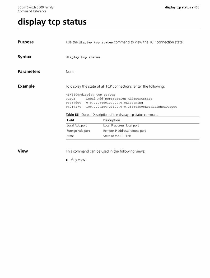
3Com Switch 5500 Family display tcp status ● 465 Command Reference
display tcp status
Purpose Use the display tcp status command to view the TCP connection state.
Syntax display tcp status
Parameters None
Example To display the state of all TCP connections, enter the following:
<SW5500>display tcp statusTCPCB Local Add:portForeign Add:portState03e37dc4 0.0.0.0:40010.0.0.0:0Listening04217174 100.0.0.204:23100.0.0.253:65508EstablishedOutput
Table 86 Output Description of the display tcp status command
View This command can be used in the following views:
■ Any view
Field Description
Local Add:port Local IP address: local port
Foreign Add:port Remote IP address; remote port
State State of the TCP link
466 ● display telnet-server source-ip 3Com Switch 5500 Family Command Reference
display telnet-server source-ip
Purpose Use the display telnet-server source-ip command to display the source IP address of the Telnet server. If no source IP address is specified, 0.0.0.0 is displayed.
Syntax display telnet-server source-ip
Parameters None
Example Display the source IP address of the Telnet server.
<S5500> display telnet-server source-ipThe source IP you specified is 192.168.1.1
View This command can be used in the following views:
■ Any view

3Com Switch 5500 Family display tftp source-ip ● 467 Command Reference
display tftp source-ip
Purpose Use the display tftp source-ip command to display the source IP address of the TFTP client. If no source IP address is specified, 0.0.0.0 is displayed.
Syntax display tftp source-ip
Parameters None
Example Display the source IP address of the TFTP client.
<S5500> system-view[S5500] display tftp source-ipThe source IP you specify is 192.168.0.1
View This command can be used in the following views:
■ Any view
468 ● display this 3Com Switch 5500 Family Command Reference
display this
Purpose Use the display this command to display the running configurations in the current view of the system.
Syntax display this [ by-linenum ]
Parameters by-linenum Displays the number of each line.
Example Display the running configuration parameters in the current view of the system with each line number.
<S5500> display this by-linenum 1: # 2: interface GigabitEthernet1/0/3 3: voice vlan enable 4: mirroring-group 2 mirroring-port inbound 5: # 6: return
View This command can be used in the following views:
■ Any view
Description After performing a group of configurations in a view, you can use the display this command to verify the configuration results by checking the currently valid parameters.
■ This command will not display the currently valid configuration parameters which have the same values with the corresponding default working parameters.
■ This command will not display the parameters whose corresponding functions do not take effect even though these parameters have been configured.
■ Executing this command in different interface views will display the configurations on the corresponding interfaces.
■ Executing this command in different protocol views will display the configurations in the corresponding protocol views.
■ Executing this command in different protocol sub-views will display the configurations in the corresponding protocol sub-views.

3Com Switch 5500 Family display time-range ● 469 Command Reference
display time-range
Purpose Use the display time-range command to view the configuration and status of the current time range. You will see the active or inactive state outputs respectively.
Syntax display time-range { all | name }
Parameters all Displays all the time-range.
name Specifies the name of the time range. Valid values are a character string that starts with a letter (a-z or A-Z), and is 1 to 32 characters long.
Example Display all the time ranges.
<SW5500>display time-range allCurrent time is 14:36:36 Apr/1/2000 Thursday
Time-range : hhy ( Inactive ) from 08:30 2-5-2005 to 18:00 2-19-2005
Time-range : hhy1 ( Inactive ) from 08:30 2-5-2003 to 18:00 2-19-2003
View This command can be used in the following views:
■ Any view
Description The system has a delay of about 1 minute when updating the ACL state, while the display time-range command applies the current time. Therefore when display time-range displays that a time range is active, the ACL using it may not have been activated yet.
Related Command time-range
470 ● display transceiver-information interface 3Com Switch 5500 Family Command Reference
display transceiver-information interface
Purpose Use the display transceiver-information interface command to display information about a specified optical port, including:
■ Hardware type
■ Interface type
■ Wavelength
■ Vender
■ Serial number
■ Transfer distance
Syntax display transceiver-information interface interface-type interface-number
Parameters interface-type Port type.
interface-number Port number.
Example Display information about the GigabitEthernet1/0/1 optical port.
<S5500> display transceiver-information interface GigabitEthernet 1/0/1Hardware Type : - Interface Type : SFP Wave Length(nm) : - Vender Name : Infineon Serial Number : 36876794 Transfer Distance(m) 9um Fiber : 0 50um Fiber : 500 62.5um Fiber : 300 Copper Line : 0
View This command can be used in the following views:
■ Any view

3Com Switch 5500 Family display trapbuffer ● 471 Command Reference
display trapbuffer
Purpose Use the display trapbuffer command to display the status of the trap buffer and the records in the trap buffer.
Syntax display trapbuffer [ unit unit-id ] [ size buffersize ]
Parameters unit-id Unit ID.
size Specifies the size of the trap buffer.
buffersize Size of the memory buffer, represented by the number of messages it holds. Valid values are 1 to 1024. If not specified, the default is 256.
Example Display the status of the trap buffer and the records in the trap buffer.
<S5500> display trapbufferTrapping Buffer Configuration and contents:enabledallowed max buffer size : 1024actual buffer size : 256channel number : 3 , channel name : trapbufferdropped messages : 0overwrote messages : 0current messages : 6
#Dec 31 14:01:25 2004 S5500 DEV/2/LOAD FINISHED: Trap 1.3.6.1.4.1.2011.2.23.1.12.1.20: frameIndex is 0, slotIndex 0.4
#Dec 31 14:01:33 2004 S5500 DEV/2/BOARD STATE CHANGE TO NORMAL: Trap 1.3.6.1.4.1.2011.2.23.1.12.1.11: frameIndex is 0, slotIndex 0.2
#Dec 31 14:01:40 2004 S5500 DEV/2/BOARD STATE CHANGE TO NORMAL: Trap 1.3.6.1.4.1.2011.2.23.1.12.1.11: frameIndex is 0, slotIndex 0.……
View This command can be used in the following views:
■ Any view
Description Executing the command with the size buffersize parameters will display the latest trap records, with the number of the records being the specified size at most.

472 ● display udp-helper server 3Com Switch 5500 Family Command Reference
display udp-helper server
Purpose Use the display udp-helper server command to view the information of destination Helper server corresponding to the VLAN interface.
Syntax display udp-helper server [ interface vlan-interface vlan_id ]
Parameters vlan_id VLAN interface ID.
Example To display the information of destination Helper server corresponding to the VLAN interface 1, enter the following:
<SW5500>display udp-helper server interface vlan-interface 1interface name server addresspackets sent VLAN-interface1 192.1.1.20
View This command can be used in the following views:
■ Any view

3Com Switch 5500 Family display udp statistics ● 473 Command Reference
display udp statistics
Purpose Use the display udp statistics command to view UDP traffic statistic information.
Syntax display udp statistics
Parameters None
Example To display the UDP traffic statistic information, enter the following:
<SW5500>display udp statisticsReceived packet:Total:0checksum error:0shorter than header:0, data length larger than packet:0no socket on port:0broadcast:0not delivered, input socket full:0input packets missing pcb cache:0Sent packet:Total:0
View This command can be used in the following views:
■ Any view
Related Command reset udp statistics

474 ● display unit 3Com Switch 5500 Family Command Reference
display unit
Purpose Using display unit unit-id interface command, you can view all port interfaces for the specified unit.
Syntax display unit unit-id interface
Parameters unit-id Specifies Unit ID. Valid values are 1 to 8.
Example Display the port information for all ports on Unit 1.
<SW5500>display unit 1 interfaceAux1/0/0 current state :DOWNLine protocol current state :DOWNInternet protocol processing : disabledDescription : Aux1/0/0 InterfaceThe Maximum Transmit Unit is 1500Data drive mode: interactive 5 minutes input rate 0.0 bytes/sec, 0.0 packets/sec 5 minutes output rate 0.0 bytes/sec, 0.0 packets/sec 0 packets input, 1000 bytes 0 packets output, 27317 bytes error: Parity 0, Frame 0, Overrun 0, FIFO 0DCD=UP DTR=UP DSR=UP RTS=UP CTS=UPEthernet1/0/1 current state : DOWN IP Sending Frames’ Format is PKTFMT_ETHNT_2, Hardware address is 00e0-fc00-5500(Omitted)
View This command can be used in the following views:
■ Any view
3Com Switch 5500 Family display user-interface ● 475 Command Reference
display user-interface
Purpose Use the display user-interface command to view information on a user interface.
Syntax display user-interface [ type number | number ] [summary]
Parameters type number Specifies the type and number of the user interface you want to display details on, for example VTY 3.
number Specifies the index number of the user interface you want to display details on.
summary Displays the summary of a user interface.
Example To display information on a user interface with an index number of 0, enter the following.
<SW5500>display user-interface aux 0
The information is displayed in the following format:
Idx Type Tx/Rx Modem Privi Auth Int 0 AUX 0 19200 - 3 P -
+ : Current user-interface is active. F : Current user-interface is active and work in async mode. Idx : Absolute index of user-interface. Type : Type and relative index of user-interface. Privi: The privilege of user-interface. Auth : The authentication mode of user-interface. Int : The physical location of UIs. A : Authentication use AAA. N : Current UI need not authentication. P : Authentication use current UI’s password.
Table 87 Output description of the display user-interface command
Field Description
+ Indicates that the user interface is in use
F Current user interface is in use and working in asynchronous mode
Idx Displays the index number of the user interface
Type Displays the type and type number of the user interface
Tx/Rx Displays the user interface speed
Modem Displays the modem operation mode
Privi Indicates the command level that can be accessed from this user interface
Auth Indicates the user interface authentication method
Int Indicates the physical location of the user interface
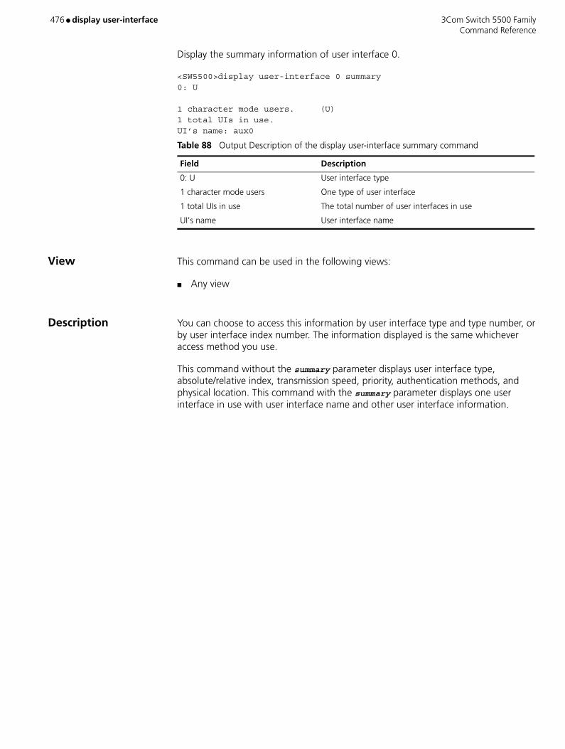
476 ● display user-interface 3Com Switch 5500 Family Command Reference
Display the summary information of user interface 0.
<SW5500>display user-interface 0 summary0: U
1 character mode users. (U)1 total UIs in use.UI’s name: aux0
View This command can be used in the following views:
■ Any view
Description You can choose to access this information by user interface type and type number, or by user interface index number. The information displayed is the same whichever access method you use.
This command without the summary parameter displays user interface type, absolute/relative index, transmission speed, priority, authentication methods, and physical location. This command with the summary parameter displays one user interface in use with user interface name and other user interface information.
Table 88 Output Description of the display user-interface summary command
Field Description
0: U User interface type
1 character mode users One type of user interface
1 total UIs in use The total number of user interfaces in use
UI’s name User interface name

3Com Switch 5500 Family display users ● 477 Command Reference
display users
Purpose Use the display users command to view information on the current user interface. Use the display users all command to view the information on all user interfaces.
Syntax display users [ all ]
Parameters all Displays information on all user interfaces.
Example To display information on the current user interface, enter the following
[SW5500]display usersThe information displays in the following format:
UI DelayTypeIPaddressUsernameUserlevelF 0 AUX 0 00:00:003
The categories of information displayed are as follows:
View This command can be used in the following views:
■ Any view
Table 89 Output description of the display users command
Field Description
F Indicates that the user interface is in use and is working in asynchronous mode
UI Number of the first list is the absolute number of user interface.
Number of the second list is the relative number of user interface
Delay Indicates the interval from the latest input until now, in seconds.
Type Indicates the user interface type.
IPaddress Displays initial connection location, namely the host IP address of the incoming connection.
Username Display the login name of the user who is using this interface
Userlevel Display the level of the user using this user interface
478 ● display version 3Com Switch 5500 Family Command Reference
display version
Purpose Use the display version command to view the software version, issue date and the basic hardware configuration information.
Syntax display version
Parameters None
Description Display the information about the system version.
<SW5500>display version
View This command can be used in the following views:
■ Any view
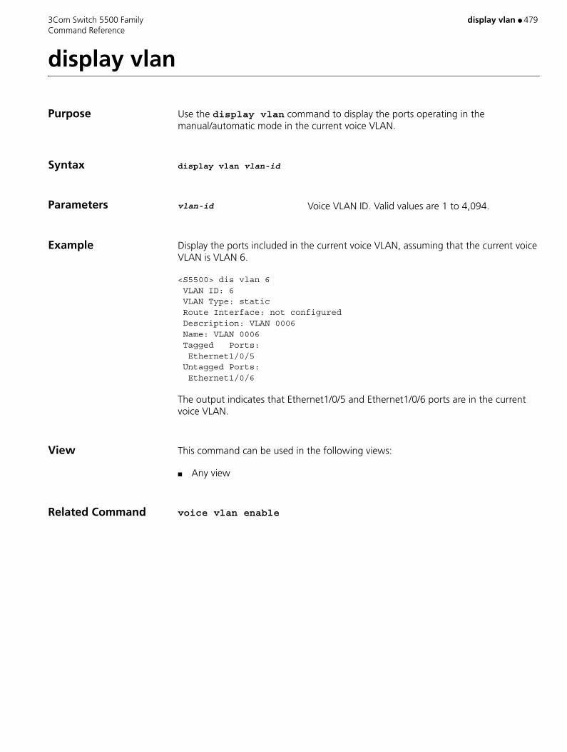
3Com Switch 5500 Family display vlan ● 479 Command Reference
display vlan
Purpose Use the display vlan command to display the ports operating in the manual/automatic mode in the current voice VLAN.
Syntax display vlan vlan-id
Parameters vlan-id Voice VLAN ID. Valid values are 1 to 4,094.
Example Display the ports included in the current voice VLAN, assuming that the current voice VLAN is VLAN 6.
<S5500> dis vlan 6 VLAN ID: 6 VLAN Type: static Route Interface: not configured Description: VLAN 0006 Name: VLAN 0006 Tagged Ports: Ethernet1/0/5 Untagged Ports: Ethernet1/0/6
The output indicates that Ethernet1/0/5 and Ethernet1/0/6 ports are in the current voice VLAN.
View This command can be used in the following views:
■ Any view
Related Command voice vlan enable
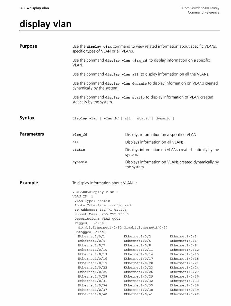
480 ● display vlan 3Com Switch 5500 Family Command Reference
display vlan
Purpose Use the display vlan command to view related information about specific VLANs, specific types of VLAN or all VLANs.
Use the command display vlan vlan_id to display information on a specific VLAN.
Use the command display vlan all to display information on all the VLANs.
Use the command display vlan dynamic to display information on VLANs created dynamically by the system.
Use the command display vlan static to display information of VLAN created statically by the system.
Syntax display vlan [ vlan_id | all | static | dynamic ]
Parameters vlan_id Displays information on a specified VLAN.
all Displays information on all VLANs.
static Displays information on VLANs created statically by the system.
dynamic Displays information on VLANs created dynamically by the system.
Example To display information about VLAN 1:
<SW5500>display vlan 1 VLAN ID: 1 VLAN Type: static Route Interface: configured IP Address: 161.71.61.206 Subnet Mask: 255.255.255.0 Description: VLAN 0001 Tagged Ports:
GigabitEthernet1/0/52 GigabitEthernet2/0/27 Untagged Ports:
Ethernet1/0/1 Ethernet1/0/2 Ethernet1/0/3Ethernet1/0/4 Ethernet1/0/5 Ethernet1/0/6Ethernet1/0/7 Ethernet1/0/8 Ethernet1/0/9Ethernet1/0/10 Ethernet1/0/11 Ethernet1/0/12Ethernet1/0/13 Ethernet1/0/14 Ethernet1/0/15Ethernet1/0/16 Ethernet1/0/17 Ethernet1/0/18Ethernet1/0/19 Ethernet1/0/20 Ethernet1/0/21Ethernet1/0/22 Ethernet1/0/23 Ethernet1/0/24Ethernet1/0/25 Ethernet1/0/26 Ethernet1/0/27Ethernet1/0/28 Ethernet1/0/29 Ethernet1/0/30Ethernet1/0/31 Ethernet1/0/32 Ethernet1/0/33Ethernet1/0/34 Ethernet1/0/35 Ethernet1/0/36Ethernet1/0/37 Ethernet1/0/38 Ethernet1/0/39Ethernet1/0/40 Ethernet1/0/41 Ethernet1/0/42

3Com Switch 5500 Family display vlan ● 481 Command Reference
Ethernet1/0/43 Ethernet1/0/44 Ethernet1/0/45Ethernet1/0/46 Ethernet1/0/47 Ethernet1/0/48GigabitEthernet1/0/50 GigabitEthernet1/0/51 Ethernet2/0/1Ethernet2/0/2 Ethernet2/0/3 Ethernet2/0/4Ethernet2/0/5 Ethernet2/0/6 Ethernet2/0/7Ethernet2/0/8 Ethernet2/0/9 Ethernet2/0/10Ethernet2/0/11 Ethernet2/0/12 Ethernet2/0/13Ethernet2/0/14 Ethernet2/0/15 Ethernet2/0/16Ethernet2/0/17 Ethernet2/0/18 Ethernet2/0/19Ethernet2/0/20 Ethernet2/0/21 Ethernet2/0/22Ethernet2/0/23 Ethernet2/0/24 GigabitEthernet2/0/25GigabitEthernet2/0/26 GigabitEthernet2/0/28
<SW5500>
View This command can be used in the following views:
■ Any view
Description The information includes: VLAN type, whether the Route interface has been configured on the VLAN, the Broadcast Suppression max-ratio, the VLAN description, and a list of the tagged and untagged ports that belong to the VLAN.
Related Command vlan

482 ● display voice vlan oui 3Com Switch 5500 Family Command Reference
display voice vlan oui
Purpose Use the display voice vlan oui command to display the OUI address supported by the current system and its relative features.
Syntax display voice vlan oui
Parameters None
Example To display the OUI address of Voice VLAN, enter the following:
<SW5500>system-view System View: return to User View with Ctrl+Z. [SW5500]display voice vlan ouiOui Address Mask Description00e0-bb00-0000 ffff-ff00-0000 3com phone0003-6b00-0000 ffff-ff00-0000 Cisco phone00e0-7500-0000 ffff-ff00-0000 Polycom phone00d0-1e00-0000 ffff-ff00-0000 Pingtel phone00aa-bb00-0000 ffff-ff00-0000 ABC
View This command can be used in the following views:
■ Any view
Related Command ■ voice vlan enable
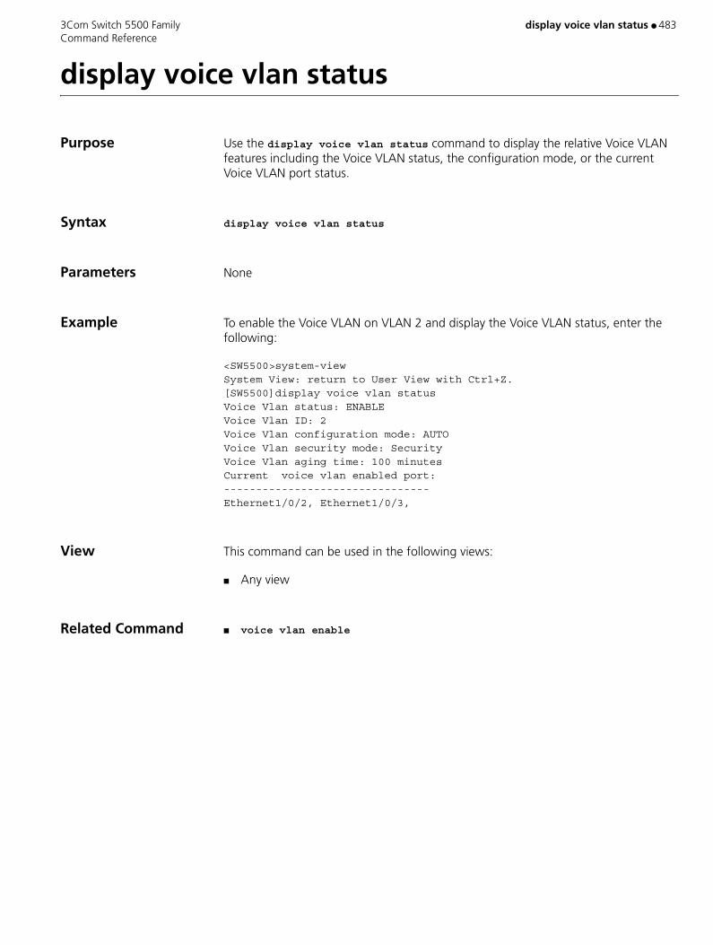
3Com Switch 5500 Family display voice vlan status ● 483 Command Reference
display voice vlan status
Purpose Use the display voice vlan status command to display the relative Voice VLAN features including the Voice VLAN status, the configuration mode, or the current Voice VLAN port status.
Syntax display voice vlan status
Parameters None
Example To enable the Voice VLAN on VLAN 2 and display the Voice VLAN status, enter the following:
<SW5500>system-viewSystem View: return to User View with Ctrl+Z.[SW5500]display voice vlan statusVoice Vlan status: ENABLEVoice Vlan ID: 2Voice Vlan configuration mode: AUTOVoice Vlan security mode: SecurityVoice Vlan aging time: 100 minutesCurrent voice vlan enabled port:--------------------------------Ethernet1/0/2, Ethernet1/0/3,
View This command can be used in the following views:
■ Any view
Related Command ■ voice vlan enable

484 ● display vrrp 3Com Switch 5500 Family Command Reference
display vrrp
Purpose Use the display vrrp command to display the information about the VRRP state or VRRP statistics.
Syntax display vrrp [ interface vlan-interface valn-id | statistics [ vlan-interface vlan-id ] ] [ virtual-router-ID ]
Parameters interface Displays VRRP information about the specified VLAN interface.
vlan-interface vlan-id Specifies a VLAN interface ID.
statistics Displays VRRP statistics.
virtual-router-ID VRRP backup group ID. Valid values are 1 to 255.
Example Display the statistics about all the backup groups on the switch.
<S5500> display vrrp statistics Interface : Vlan-interface10 VRID : 1 CheckSum Errors : 0 Version Errors : 0 VRID Errors : 0 Advertisement Interval Errors : 0 IP TTL Errors : 0 Auth Failures : 0 Invalid Auth Type : 0 Auth Type Mismatch : 0 Packet Length Errors : 0 Address List Errors : 0 Become Master : 2 Priority Zero Pkts Rcvd : 0 Advertise Rcvd : 0 Priority Zero Pkts Sent : 1 Invalid Type Pkts Rcvd : 0
Table 90 Description on the fields of the display vrrp command
Field Description
Interface Interface in which the backup group resides
VRID Backup group ID
CheckSum Errors Times of checksum error
Version Errors Times of version error
VRID Errors Times of backup group ID error
Advertisement Interval Errors
Times of advertisement time interval error
IP TTL Errors Times of TTL error
Auth Failures Times of authentication error
Invalid Auth Type Times of invalid authentication type
Auth Type Mismatch Mismatched times of authentication type
Packet Length Errors Times of VRRP packet length error
Address List Errors Times of the virtual IP address list error
Become Master Times of becoming a master
Priority Zero Pkts Rcvd Number of the received advertisement packets with the priority of 0
Advertise Rcvd Number of the received advertisement packets
Priority Zero Pkts Sent Number of the sent advertisement packets with the priority of 0
3Com Switch 5500 Family display vrrp ● 485 Command Reference
View This command can be used in the following views:
■ Any view
Description When VRRP status information is displayed:
■ If the interface index and backup group ID are not specified, the state information about all the backup groups on the switch is displayed.
■ If only the interface index is specified, the state information about all the backup groups on the interface is displayed.
■ If both the interface index and backup group ID are specified, the state information about the specified backup group on the interface is displayed.
When VRRP statistics information is displayed:
■ If the interface index and backup group ID are not specified, the statistics about all the backup groups on the switch is displayed.
■ If only the interface index is specified, the statistics about all the backup groups on the interface is displayed.
■ If both the interface index and backup group ID are specified, the statistics about the specified backup group on the interface is displayed.
Invalid Type Pkts Rcvd Times of packet type error
Table 90 Description on the fields of the display vrrp command (continued)
Field Description
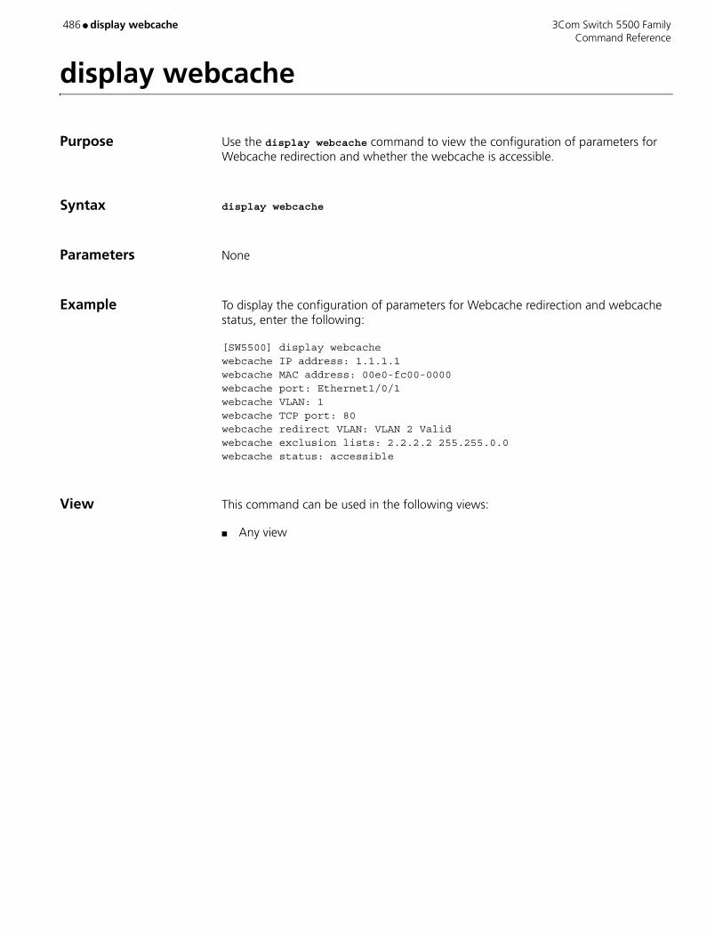
486 ● display webcache 3Com Switch 5500 Family Command Reference
display webcache
Purpose Use the display webcache command to view the configuration of parameters for Webcache redirection and whether the webcache is accessible.
Syntax display webcache
Parameters None
Example To display the configuration of parameters for Webcache redirection and webcache status, enter the following:
[SW5500] display webcachewebcache IP address: 1.1.1.1webcache MAC address: 00e0-fc00-0000webcache port: Ethernet1/0/1webcache VLAN: 1webcache TCP port: 80webcache redirect VLAN: VLAN 2 Validwebcache exclusion lists: 2.2.2.2 255.255.0.0webcache status: accessible
View This command can be used in the following views:
■ Any view
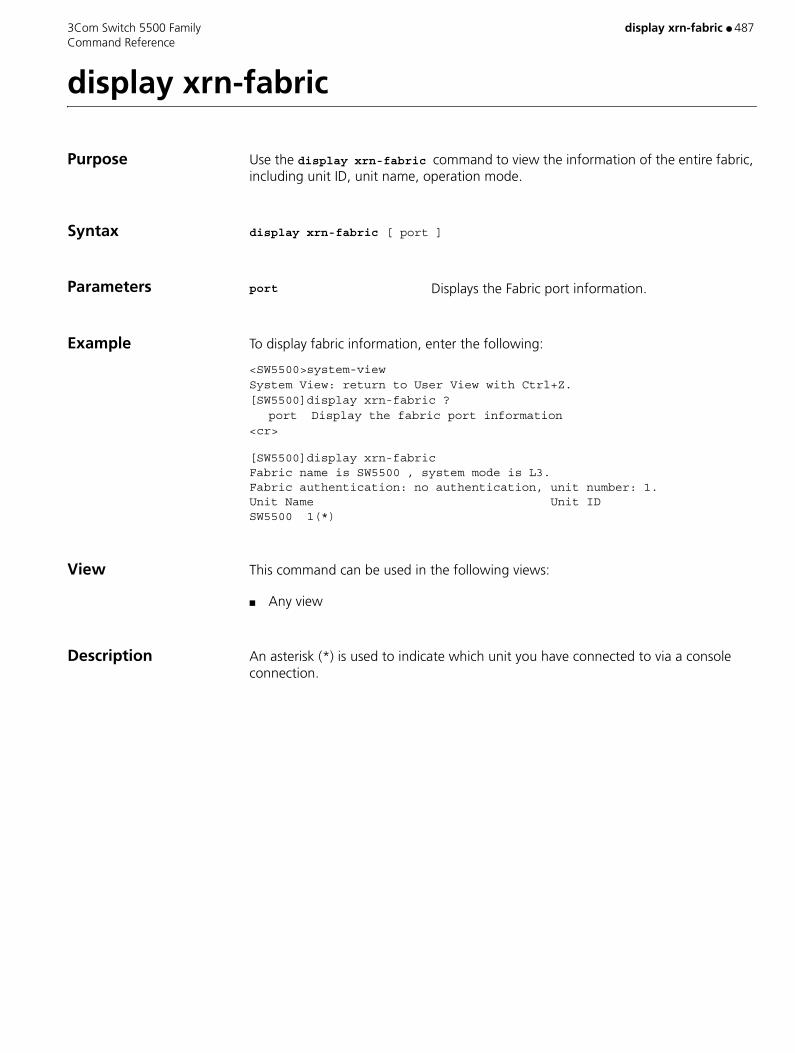
3Com Switch 5500 Family display xrn-fabric ● 487 Command Reference
display xrn-fabric
Purpose Use the display xrn-fabric command to view the information of the entire fabric, including unit ID, unit name, operation mode.
Syntax display xrn-fabric [ port ]
Parameters port Displays the Fabric port information.
Example To display fabric information, enter the following:
<SW5500>system-viewSystem View: return to User View with Ctrl+Z.[SW5500]display xrn-fabric ?
port Display the fabric port information<cr>
[SW5500]display xrn-fabric Fabric name is SW5500 , system mode is L3. Fabric authentication: no authentication, unit number: 1. Unit Name Unit ID SW5500 1(*)
View This command can be used in the following views:
■ Any view
Description An asterisk (*) is used to indicate which unit you have connected to via a console connection.

488 ● dldp 3Com Switch 5500 Family Command Reference
dldp
Purpose Use the dldp command to either enable or disable the DLDP on either all the optical switches or current switch.
In System view, use the dldp command to either enable or disable the DLDP globally on all optical ports of the switch.
In Ethernet Port view, use the dldp command to enable or disable the DLDP on the current port.
Syntax dldp { enable | disable }
Parameters None
Default By default, DLDP is disabled.
When you use the dldp enable/dldp disable command in System view to enable/disable DLDP globally on all optical ports of the switch, this command is valid only for the existing optical ports on the device. It is not valid for those added subsequently.
Example Enable DLDP globally on all optical ports of the switch.
<S5500> system-viewSystem View: return to User View with Ctrl+Z.[S5500] dldp enableAll fiber ports except fabric ports have enabled DLDP!
View This command can be used in the following views:
■ System view
■ Ethernet Port view
Description In system view:
■ Use the dldp enable command to enable DLDP globally on all optical ports of the switch.
■ Use the dldp disable command to disable DLDP globally on all optical ports of the switch.

3Com Switch 5500 Family dldp ● 489 Command Reference
In Ethernet port view:
■ Use the dldp enable command to enable DLDP on the current port.
■ Use the dldp disable command to disable DLDP on the current port.
The commands can apply to a non-optical port as well as an optical port.
490 ● dldp authentication-mode 3Com Switch 5500 Family Command Reference
dldp authentication-mode
Purpose Use the dldp authentication-mode command to set the DLDP authentication mode and password for the ports of the local and peer devices.
Syntax dldp authentication-mode { none | simple password | md5 password }
undo dldp authentication-mode
Parameters md5 Sets the authentication mode to MD5.
none Performs no authentication.
simple Sets the authentication mode to plain text.
password Authentication password, consisting of a string in plain text 1 to 16 characters long.
Example Set the DLDP authentication mode and password for the ports connected with fiber cables or copper twisted pairs, between the two devices (S5500A and S5500B) to plain text and password1 respectively.
■ Configure S5500A:
<S5500A> system-viewSystem View: return to User View with Ctrl+Z.[S5500A] dldp authentication-mode simple password1
■ Configure S5500B:
<S5500B> system-viewSystem View: return to User View with Ctrl+Z.[S5500B] dldp authentication-mode simple password1
View This command can be used in the following views:
■ System view
Description By default, authentication mode is none.
When you configure the DLDP authentication mode and authentication password, make sure the same DLDP authentication mode and password are set for the ports of the local and peer devices, which are connected with the optical fiber cable or copper twisted pair. Otherwise, DLDP authentication fails. DLDP cannot work when DLDP authentication fails.
Related Command dldp unidirectional-shutdown

3Com Switch 5500 Family dldp interval ● 491 Command Reference
dldp interval
Purpose Use the dldp interval command to set the time interval for sending advertisement packets.
Use the undo dldp interval command to restore the default time interval.
Syntax dldp interval integer
undo dldp interval
Parameters integer Time interval for sending DLDP frames. Valid values are 5 to 100 seconds. If not specified, the default time interval is 10 seconds.
Example Set the time interval for sending advertisement packets to 20 seconds.
<S5500> system-viewSystem View: return to User View with Ctrl+Z.[S5500] dldp interval 20
View This command can be used in the following views:
■ System view
Description For any port where DLDP is enabled, when DLDP is in advertisement state, it sends advertisement packets through the port at the intervals of this value.
Note:
■ The time interval you define applies to all ports with DLDP enabled.
■ The time interval should be shorter than one-third of the STP convergence time, which is generally 30 seconds. If too long time interval is set, an STP loop may occur before DLDP shut down unidirectional links. On the contrary, if too short time interval is set, network traffic increases, and port bandwidth is reduced.
492 ● dldp reset 3Com Switch 5500 Family Command Reference
dldp reset
Purpose Use the dldp reset command to reset the DLDP status of either the current port or all the ports disabled by DLDP.
In System view, use the dldp reset command to reset the DLDP status of all the ports disabled by DLDP.
In Ethernet Port view, use the dldp reset command to reset the DLDP status of the current port disabled by DLDP.
Syntax dldp reset
Parameters None
Example Reset the DLDP status of all the ports disabled by DLDP.
<S5500> system-viewSystem View: return to User View with Ctrl+Z.[S5500] dldp reset
View This command can be used in the following views:
■ System view
■ Ethernet Port view
Description After the dldp reset command is executed, the DLDP status of these ports changes from disable to active and DLDP restarts to probe the link status of the fiber cables or copper twisted pairs.
Related Commands ■ dldp
■ dldp unidirectional-shutdown

3Com Switch 5500 Family dldp unidirectional-shutdown ● 493 Command Reference
dldp unidirectional-shutdown
Purpose Use the dldp unidirectional-shutdown command to set DLDP handling mode when a unidirectional link is found.
Use the undo dldp unidirectional-shutdown command to restore the default setting.
Syntax dldp unidirectional-shutdown { auto | manual }
undo dldp unidirectional-shutdown
Parameters auto In this mode, when DLDP finds a unidirectional link or finds (in the enhanced mode) that the peer end is down, it automatically disables the corresponding port. If no handling mode is specified, auto is the default mode used.
manual In this mode, when DLDP finds an unidirectional link or finds (in the enhanced mode) that the peer end is down, instead of disabling the port automatically, it stops the DLDP packets sending/receiving on the port and prompts the user to disable the port manually.
Example Configure DLDP to automatically disable the corresponding port when a unidirectional link is found.
<S5500> system-viewSystem View: return to User View with Ctrl+Z.[S5500] dldp unidirectional-shutdown auto
View This command can be used in the following views:
■ System view
Related Command dldp work-mode
494 ● dldp work-mode 3Com Switch 5500 Family Command Reference
dldp work-mode
Purpose Use the dldp work-mode command to set the DLDP operating mode.
Use the undo dldp work-mode command to restore the default DLDP operating mode.
Syntax dldp work-mode { enhance | normal }
undo dldp work-mode
Parameters enhance Configures the DLDP to work in enhanced mode. In this mode, DLDP probes actively whether neighbors exist when neighbor entries age out.
normal Configures the DLDP to work in normal mode. In this mode, DLDP does not probe actively whether neighbors exist when neighbor entries age out. If no mode is specified, normal is the default mode used.
Example Configure DLDP to work in enhanced mode.
<S5500> system-viewSystem View: return to User View with Ctrl+Z.[S5500] dldp work-mode enhance
View This command can be used in the following views:
■ System view

3Com Switch 5500 Family dns-list ● 495 Command Reference
dns-list
Purpose Use the dns-list command to configure one or multiple DNS server IP addresses for a global DHCP address pool.
Use the undo dns-list command to remove one or all DNS server IP addresses configured for the DHCP address pool.
Syntax dns-list ip-address&<1-8>
undo dns-list { ip-address | all }
Parameters ip-address&<1-8> IP address of a DNS server. &<1-8> string means you can provide up to eight DNS server IP addresses. When inputting more than one IP address, separate two neighboring IP addresses with a space.
all Specifies all configured DNS server IP addresses.
Default By default, no DNS server IP address is configured.
Example Enter system view.
<S5500> system-viewSystem View: return to User View with Ctrl+Z.
Configure the DNS server IP address 1.1.1.254 for global DHCP address pool 0.
[S5500] dhcp server ip-pool 0[S5500-dhcp-pool-0] dns-list 1.1.1.254
View This command can be used in the following views:
■ DHCP Address Pool view
Description If you execute the dns-list command repeatedly, the new configuration overwrites the previous one.
This command applies only to the S5500-EI series among Switch 5500-Series Switches.
Related Commands ■ dhcp server dns-list
■ dhcp server ip-pool
496 ● domain 3Com Switch 5500 Family Command Reference
domain
Purpose Use the domain command to configure an ISP domain or enter the view of an existing ISP domain.
Use the undo domain command to cancel a specified ISP domain.
Syntax domain { isp-name | default { disable | enable isp-name }}
undo domain isp-name
Parameters isp-name Specifies an ISP domain name. The name is expressed with a character string not exceeding 24 characters, excluding “/”, “: ”, “*”, “? ”, “<”, and “>”.
default enable isp-name Enables the default ISP domain specified by isp-name.
default disable Restores the default ISP domain to system.
Default By default, a domain named system has been created in the system. The attributes of system are all default values.
Example To create a new ISP domain, marlboro.net, and enters its view, enter the following:
<SW5500>system-viewSystem View: return to User View with Ctrl+Z.[SW5500]domain marlboro.netNew Domain added.[SW5500-isp-marlboro.net]
View This command can be used in the following views:
■ System view
Description ISP domain is a group of users belonging to the same ISP. Generally, for a username in the userid@isp-name format, taking [email protected] as an example, the isp-name (that is, 3Com163.net) following the @ is the ISP domain name. When 3Com 5500 Series Ethernet Switches control user access, as for an ISP user whose username is in userid@isp-name format, the system will take userid part as username for identification and take isp-name part as domain name.
The purpose of introducing ISP domain settings is to support the application environment with several ISP domains. In this case, an access device may have supplicants from different ISP domains. Because the attributes of ISP users, such as username and password structures, service types, may be different, it is necessary to separate them by setting ISP domains. In ISP Domain View, you can configure a

3Com Switch 5500 Family domain ● 497 Command Reference
complete set of exclusive ISP domain attributes for each ISP domain, which includes AAA schemes (RADIUS scheme applied and so forth.)
For a Switch, each supplicant belongs to an ISP domain. The system supports up to 16 ISP domains. If a user has not reported its ISP domain name, the system will put it into the default domain.
When this command is used, if the specified ISP domain does not exist, the system will create a new ISP domain. All the ISP domains are in the active state when they are created.
Related Commands ■ access-limit
■ display domain
■ radius-scheme
■ state

498 ● domain-name 3Com Switch 5500 Family Command Reference
domain-name
Purpose Use the domain-name command to configure a domain name for the DHCP clients of a global DHCP address pool.
Use the undo domain-name command to remove the domain name.
Syntax domain-name domain-name
undo domain-name
Parameters domain-name Domain name for the DHCP clients of a global DHCP address pool, consisting of a string from 3 to 50 characters long.
Default By default, no domain name is configured for the DHCP clients of a global DHCP address pool.
Example Enter system view.
<S5500> system-viewSystem View: return to User View with Ctrl+Z.
Configure the domain name mydomain.com for the DHCP clients of the global DHCP address pool 0.
[S5500] dhcp server ip-pool 0[S5500-dhcp-pool-0] domain-name mydomain.com
View This command can be used in the following views:
■ DHCP Address Pool view
Description This command applies only to the S5500-EI series among Switch 5500-Series Switches.
Related Commands ■ dhcp server domain-name
■ dhcp server ip-pool
3Com Switch 5500 Family dot1x ● 499 Command Reference
dot1x
Purpose Use the dot1x command to enable 802.1x on the specified port or globally, (that is on the current device).
Use the undo dot1x command to disable the 802.1x on the specified port or globally.
Syntax dot1x [ interface interface-list ]
undo dot1x [ interface interface-list ]
Parameters interface interface-list Ethernet port list including several Ethernet ports. interface-list = { interface-num [ to interface-num ] } & < 1-10 >. interface-num specifies a single Ethernet port in the format interface-num = { interface-type interface-num | interface-name }, where interface-type specifies the port type, interface-num specifies the port number and interface-name specifies the port name. For the respective meanings and value ranges, read the parameter of the Port Configuration section.
Default By default, 802.1x is disabled on all the ports and globally on the device.
Example To enable 802.1x on Ethernet 1/0/1, enter the following.
<SW5500>system-viewSystem View: return to User View with Ctrl-Z[SW5500]dot1x interface ethernet 1/0/1To enable 802.1x globally, enter the following. [SW5500]dot1x
View This command can be used in the following views:
■ Ethernet Port view
Description This command is used to enable the 802.1x on the current device or on the specified port. When it is used in System View, if the parameter ports-list is not specified, 802.1x will be globally enabled. If the parameter ports-list is specified, 802.1x will be enabled on the specified port. When this command is used in Ethernet Port View, the parameter interface-list cannot be entered and 802.1x can only be enabled on the current port.
The configuration command can be used to configure the global or port 802.1x performance parameters before or after 802.1x is enabled. Before 802.1x is enabled

500 ● dot1x 3Com Switch 5500 Family Command Reference
globally, if the parameters are not configured globally or for a specified port, they will maintain the default values.
After the global 802.1x performance is enabled, only when port 802.1x performance is enabled will the configuration of 802.1x become effective on the port.
Related Command display dot1x

3Com Switch 5500 Family dot1x authentication-method ● 501 Command Reference
dot1x authentication-method
Purpose Use the dot1x authentication-method command to set 802.1x authentication mode.
Use the undo dot1x authentication-method command to revert to the default 802.1x authentication mode.
Syntax dot1x authentication-method { chap | pap | eap }
undo dot1x authentication-method
Parameters chap Authenticates supplicant systems using challenge handshake authentication protocol (CHAP). CHAP is a three-way handshake authentication protocol. It has satisfactory security performance and is securer than other authentication modes. With this protocol employed, only usernames are transmitted for supplicant system to be authenticated. If no value is specified, CHAP is the default 802.1x authentication mode.
pap Authenticates supplicant systems using password authentication protocol (PAP). With this protocol employed, passwords are transmitted in plain text.
eap Authenticates supplicant systems using extensible authentication protocol (EAP). With this protocol employed, authentication information about supplicant systems is sent to authentication servers in the form of EAP packet. To authenticate supplicant systems using PEAP, EAP-TLS, EAP-TTLS, or EAP-MD5, you can specify the eap keyword.
Example Enter system view.
<S5500> system-view
Specify to authenticate supplicant systems using EAP.
[S5500] dot1x authentication-method eap
View This command can be used in the following views:
■ System view
Related Command display dot1x

502 ● dot1x authentication-method 3Com Switch 5500 Family Command Reference
dot1x authentication-method
Purpose Use the dot1x authentication-method command to configure the authentication method for the 802.1x user.
Use the undo dot1x authentication-method command to restore the default authentication method of the 802.1x user.
Syntax dot1x authentication-method { chap | pap | eap md5-challenge }
undo dot1x authentication-method
Parameters Chap Use CHAP authentication method. If no other authentication method is specified, CHAP authentication is used for 802.1x user authentication.
Pap Use PAP authentication method.
Eap Use EAP authentication method. At present, only md5 encryption method is available
Example Configure 802.1x user to use PAP authentication
<SW5500>system-viewSystem View: return to User View with Ctrl-Z[SW5500]dot1x authentication-method pap
View This command can be used in the following views:
■ System view
Description Password Authentication Protocol (PAP) is a kind of authentication protocol with two handshakes. It sends the password in the form of simple text.
Challenge Handshake Authentication Protocol (CHAP) is a kind of authentication protocol with three handshakes. It only transmits the username, not the password. CHAP is more secure and reliable.
In the process of EAP authentication, the Switch directly sends authentication information of an 802.1x user to a RADIUS server in the form of an EAP packet. It is not necessary to transfer the EAP packet to a standard RADIUS packet first and then send it to RADIUS server.
To use PAP, CHAP or EAP authentication, RADIUS server should support PAP, CHAP or EAP authentication respectively.
Related Command display dot1x

3Com Switch 5500 Family dot1x dhcp-launch ● 503 Command Reference
dot1x dhcp-launch
Purpose Use the dot1x dhcp-launch command to set 802.1x to prevent the Switch from triggering user ID authentication for users who configure static IP addresses in a DHCP environment.
Use the undo dot1x dhcp-launch command to allow the Switch to trigger ID authentication.
Syntax dot1x dhcp-launch
undo dot1x dhcp-launch
Parameters None
Default By default, the Switch can trigger user ID authentication for users who configure static IP addresses in a DHCP environment.
Example Prevent the Switch from triggering the authentication ID for users who configure static IP addresses in a DHCP environment.
<SW5500>system-viewSystem View: return to User View with Ctrl-Z[SW5500]dot1x dhcp-launch
View This command can be used in the following views:
■ System view
Related Command dot1x
504 ● dot1x guest-vlan 3Com Switch 5500 Family Command Reference
dot1x guest-vlan
Purpose Use the dot1x guest-vlan command to enable the Guest VLAN function for specified Ethernet ports.
Use the undo dot1x guest-vlan command to disable the Guest VLAN function for specified Ethernet ports.
Syntax dot1x guest-vlan vlan-id [ interface interface-list ]
undo dot1x guest-vlan vlan-id [ interface interface-list ]
Parameters vlan-id VLAN ID to be assigned to the Guest VLAN. This argument ranges from 1 to 4,094. If not specified, the default is 1.
interface-list List of Ethernet ports for which the Guest VLAN function is to be enabled. You can specify multiple Ethernet ports by providing this argument in the form of interface-list = { interface-type interface-number [ to interface-type interface-num ] } &<1-10>, where &<1-10> means that you can provide up to 10 port indexes/port index lists for this argument.
Note:
■ When being executed in system view, these two commands apply to all ports if you do not provide the interface-list argument. If you provide this argument, these two commands apply to the specified ports.
■ When being executed in Ethernet port view, these two commands apply to the current port and the interface-list argument is not needed.
Example Enter system view.
<S5500> system-view
Create VLAN 2.
[S5500] vlan 2
Enter Ethernet1/0/1 port view.
[S5500] interface ethernet1/0/1
Configure the port to operate in the port-based authentication mode.
[S5500-Ethernet1/0/1] dot1x port-method portbased
Configure VLAN 2 to be a Guest VLAN.
[S5500-Ethernet1/0/1] dot1x guest-vlan 2
3Com Switch 5500 Family dot1x guest-vlan ● 505 Command Reference
View This command can be used in the following views:
■ System view
■ Ethernet Port view
Description CAUTION:
The Guest VLAN function is available only when the switch operates in the port-based authentication mode.
Only one Guest VLAN can be configured for a switch.
Supplicant systems that are not authenticated, fail to pass the authentication, or are offline belong to Guest VLANs.
Before configuring the Guest VLAN function, make sure the VLAN to be specified as the Guest VLAN already exists.

506 ● dot1x max-user 3Com Switch 5500 Family Command Reference
dot1x max-user
Purpose Use the dot1x max-user command to configure a limit to the amount of supplicants on the specified interface using 802.1x.
Use the undo dot1x max-user command to restore the default value.
Syntax dot1x max-user user-number [ interface interface-list ]
undo dot1x max-user [ interface interface-list ]
Parameters user-number Specifies the limit to the amount of supplicants on the port, ranging from 1 to 1024. If not specified, the default maximum user number is 1024.
interface interface-list Ethernet interface list including several Ethernet interfaces, expressed in the format interface-list = { interface-num [ to interface-num ] } & < 1-10 >. interface-num specifies a single Ethernet interface in the format interface-num = { interface-type interface-num | interface-name }, where interface-type specifies the interface type, interface-num specifies the interface number and interface-name specifies the interface name. For the respective meanings and value ranges, see the parameters in the Port Command chapter.
Example Configure the interface Ethernet 1/0/2 to hold no more than 32 802.1x users.
<SW5500>system-viewSystem View: return to User View with Ctrl-Z[SW5500]dot1x max-user 32 interface ethernet 1/0/2
View This command can be used in the following views:
■ Ethernet Port view
Description This command is used for setting a limit to the amount of supplicants that 802.1x can hold on the specified interface. This command takes effect on the interface specified by the parameter interface-list when executed in System View. It takes effect on all the interfaces when no interface is specified. The parameter interface-list cannot be entered when the command is executed in Ethernet Port View and it takes effect only on the current interface.
Related Command display dot1x
3Com Switch 5500 Family dot1x port-control ● 507 Command Reference
dot1x port-control
Purpose Use the dot1x port-control command to configure the mode for 802.1x to perform access control on the specified interface.
Use the undo dot1x port-control command to restore the default access control mode.
Syntax dot1x port-control { auto | authorized-force | unauthorized-force } [ interface interface-list ]
undo dot1x port-control [ interface interface-list ]
Parameters auto Automatic identification mode, configuring the initial state of the interface as unauthorized. The user is only allowed to receive or transmit EAPoL packets but not to access the network resources. If the user passes the authentication flow, the interface will Switch over to the authorized state and then the user is allowed to access the network resources. If not specified, auto is the default identification mode.
authorized-force Forced authorized mode, configuring the interface to always stay in authorized state and the user is allowed to access the network resources without authentication/authorization.
unauthorized-force Forced unauthorized mode, configuring the interface to always stay in non-authorized mode and the user is not allowed to access the network resources.
interface interface-list Ethernet interface list including several Ethernet interfaces, expressed in the format interface-list = { interface-num [ to interface-num ] } & < 1-10 >. interface-num specifies a single Ethernet interface in the format interface-num = { interface-type interface-num | interface-name }, where interface-type specifies the interface type, interface-num specifies the interface number and interface-name specifies the interface name. For the respective meanings and value ranges, see the parameters of the Port Command chapter.
Example To configure the interface Ethernet 1/0/2 to be in force-unauthorized state, enter the following:
<SW5500>system-viewSystem View: return to User View with Ctrl-Z[SW5500]dot1x port-control force-unauthorized interface ethernet 1/0/2

508 ● dot1x port-control 3Com Switch 5500 Family Command Reference
View This command can be used in the following views:
■ Ethernet Port view
Description This command is used to set the mode, or the interface state, for 802.1x to perform access control on the specified interface. This command has an effect on the interface specified by the parameter interface-list when executed in System View. It has an effect on all the interfaces when no interface is specified. The parameter interface-list cannot be entered when the command is executed in Ethernet Port View and it has an effect only on the current interface.
Related Command display dot1x

3Com Switch 5500 Family dot1x port-method ● 509 Command Reference
dot1x port-method
Purpose Use the dot1x port-method command to configure the base for 802.1x to perform access control on the specified interface.
Use the undo dot1x port-method command to restore the default access control base.
Syntax dot1x port-method { macbased | portbased } [ interface interface-list ]
undo dot1x port-method [ interface interface-list ]
Parameters macbased Configures the 802.1x authentication system to perform authentication on the supplicant based on MAC address. If not specified, macbased is the default value used.
portbased Configures the 802.1x authentication system to perform authentication on the supplicant based on interface number.
interface interface-list Ethernet interface list including several Ethernet interfaces, expressed in the format interface-list = { interface-num [ to interface-num ] } & < 1-10 >. interface-num specifies a single Ethernet interface in the format interface-num = { interface-type interface-num | interface-name }, where interface-type specifies the interface type, interface-num specifies the interface number and interface-name specifies the interface name. For the respective meanings and value ranges, see the parameters in the Port Command chapter.
View This command can be used in the following views:
■ Ethernet Port view
Example To authenticate the supplicant based on the interface number on Ethernet 1/0/3, enter the following:
<SW5500>system-viewSystem View: return to User View with Ctrl-Z[SW5500]dot1x port-method portbased interface ethernet 1/0/3
Description This command is used to set the base for 802.1x to perform access control, namely authenticate the users, on the specified interface. When macbased is used, the users accessing this interface must be authenticated independently, and as such will be able to access the network as long as they independently require. When portbased is used, only the first user on that port needs to be authenticated. Subsequent users

510 ● dot1x port-method 3Com Switch 5500 Family Command Reference
accessing the network through this port are considered authenticated. However if the original user terminates his connection, the other users will need to be re-authenticated.
This command has an effect on the interface specified by the parameter interface-list when executed in System View. It has an effect on all the interfaces when no interface is specified. The parameter interface-list cannot be input when the command is executed in Ethernet Port View and it has an effect only on the current interface.
Related Command display dot1x

3Com Switch 5500 Family dot1x quiet-period ● 511 Command Reference
dot1x quiet-period
Purpose Use the dot1x quiet-period command to enable the quiet-period timer.
Use the undo dot1x quiet-period command to disable this timer.
Syntax dot1x quiet-period
undo dot1x quiet-period
Parameters None
Default By default, the quiet-period timer is disabled.
Example To enable quiet-period timer, enter the following:
<SW5500>system-viewSystem View: return to User View with Ctrl-Z[SW5500]dot1x quiet-period
View This command can be used in the following views:
■ System view
Description If an 802.1x user has not been authenticated, the Authenticator will keep quiet for a while (which is specified by quiet-period timer) before launching the authentication again. During the quiet period, the Authenticator does not do anything related to 802.1x authentication.
Related Commands ■ display dot1x
■ dot1x timer
512 ● dot1x retry 3Com Switch 5500 Family Command Reference
dot1x retry
Purpose Use the dot1x retry command to configure the maximum times a Switch can retransmit the authentication request frame to the supplicant.
Use the undo dot1x retry command to restore the default maximum retransmission time.
Syntax dot1x retry max-retry-value
undo dot1x retry
Parameters max-retry-value Specifies the maximum times an Ethernet switch can retransmit the authentication request frame to the supplicant, ranging from 1 to 10. If not specified, the default value is 3, meaning that the switch can retransmit the authentication request frame to the supplicant 3 times.
Example To configure the current device to transmit an authentication request frame to the user for no more than 9 times, enter the following:
<SW5500>system-viewSystem View: return to User View with Ctrl-Z[SW5500]dot1x retry 9
View This command can be used in the following views:
■ System view
Description After the Switch has transmitted an authentication request frame to the user for the first time, if no user response is received during the specified time-range, the Switch will re-transmit authentication request to the user. This command is used to specify how many times the Switch can re-transmit the authentication request frame to the supplicant. When the time is 1, the Switch is configured to transmit the authentication request frame only once. 2 indicates that the Switch is configured to transmit authentication request frame once again when no response is received for the first time and so on. This command has an effect on all the ports after configuration.
Related Command display dot1x

3Com Switch 5500 Family dot1x retry-version-max ● 513 Command Reference
dot1x retry-version-max
Purpose Use the dot1x retry-version-max command to set the maximum number of retries for a switch to send version request packets to an online supplicant system.
Use the undo dot1x retry-version-max command to revert to the default maximum number of retries.
Syntax dot1x retry-version-max max-retry-version-value
undo dot1x retry-version-max
Parameters max-retry-version-value Maximum number of retries to send version request packets to an online supplicant system. This argument ranges from 1 to 10. If not specified, the default is 3.
Example Enter system view.
<S5500> system-view
Configure the maximum number of retries for the switch to send version request packets to online supplicant systems to be 6.
[S5500] dot1x retry-version-max 6
View This command can be used in the following views:
■ System view
Description After sending a version request packet to a supplicant system, a switch sends another one to the supplicant system if it does not receive the response from the supplicant system for the period set by the version checking timer. It continues to send version request packets to the supplicant system if it still does not receive the response from the supplicant system. Such a process goes on and on until the maximum number of retries is reached. If the maximum number of retries is reached and the supplicant system still does not respond, the switch ceases checking the client version of the supplicant system and continues the followed authentication procedures.
These two commands apply to all ports with the version checking function enabled.
Related Commands ■ display dot1x
■ dot1x timer

514 ● dot1x supp-proxy-check 3Com Switch 5500 Family Command Reference
dot1x supp-proxy-check
Purpose Use the dot1x supp-proxy-check command to enable the supplicant system checking function for specified Ethernet ports.
Use the undo dot1x supp-proxy-check command to disable the supplicant system checking function for specified Ethernet ports.
Syntax dot1x supp-proxy-check { logoff | trap } [ interface interface-list ]
undo dot1x supp-proxy-check { logoff | trap } [ interface interface-list ]
Parameters logoff Disconnects a supplicant system if the supplicant system is detected logging in through a proxy or through more than one network adapters.
trap Sends Trap packets if the supplicant system is detected logging in through a proxy or through more than one network adapters.
interface interface-list Specifies a list of Ethernet ports. You can specify multiple Ethernet ports by providing this argument in the form of interface-list = { interface-type interface-number [ to interface-type interface-num ] } &<1-10>, where &<1-10> means that you can provide up to 10 port indexes/port index lists for this argument.
■ When being executed in system view, these two commands apply to all ports if you do not provide the interface-list argument. If you provide this argument, these two commands apply to the specified ports.
■ When being executed in Ethernet port view, these two commands apply to the current port and the interface-list argument is not needed.
Example Enter system view.
<S5500> system-view
Configure to disconnect the supplicant systems connected to Ethernet1/0/1 through Ethernet1/0/8 ports if the supplicant systems are detected logging in through proxies.
[S5500] dot1x supp-proxy-check logoff
[S5500] dot1x supp-proxy-check logoff interface Ethernet 1/0/1 to Ethernet 1/0/8
Configure to send Trap packets if the supplicant systems connected to Ethernet1/0/9 port are detected logging in through proxies.
[S5500] dot1x supp-proxy-check trap[S5500] dot1x supp-proxy-check trap interface Ethernet 1/0/9
3Com Switch 5500 Family dot1x supp-proxy-check ● 515 Command Reference
View This command can be used in the following views:
■ System view
■ Ethernet Port view
Description By default, the supplicant system checking function is disabled on an Ethernet port.
The supplicant system checking function checks for:
■ Supplicant systems logging in through proxies
■ Supplicant systems logging in through IE proxies
■ Whether or not a supplicant system logs in with more than one network adapters installed in it being active
A 3Com Switch 5500 Family switch can optionally take the following measures against any of the three cases:
■ Disconnecting the supplicant system and sending Trap packets (This can be achieved by using the dot1x supp-proxy-check logoff command.)
■ Sending Trap packets without disconnecting the supplicant system (This can be achieved by using the dot1x supp-proxy-check trap command.)
To achieve this function, following are to meet for 802.1x clients and CAMS.
■ The 802.1x clients are capable of detecting multiple network adapters, proxies, and IE proxies.
■ CAMS is configured to disable use of multiple network adapters, proxies, or IE proxies.
By default, an 802.1x client allows the use of multiple network adapters, proxies, and IE proxies. If CAMS is configured to disable the use of multiple network adapters, proxies, or IE proxies, it prompts the 802.1x client to disable use of multiple network adapters, proxies, or IE proxies through messages after the supplicant system passes the authentication.
■ This function needs the support of 3Com’s 802.1x client.
■ As for the proxy detecting function, you need to enable this function on both the 802.1x client and CAMS. You need also to enable client version detecting on the switch (refer to the dot1x version-check command for more).
■ To utilize the supplicant system checking function on a port, you need to enable the function in system view and then in Ethernet port view.
Related Command display dot1x

516 ● dot1x timer 3Com Switch 5500 Family Command Reference
dot1x timer
Purpose Use the dot1x timer command to configure the 802.1x timers.
Use the undo dot1x timer command to restore the default values.
Syntax dot1x timer { handshake-period handshake-period-value | quiet-period quiet-period-value | tx-period tx-period-value | supp-timeout supp-timeout-value | server-timeout server-timeout-value }
undo dot1x timer { handshake-period | quiet-period | tx-period | supp-timeout | server-timeout }
Parameters handshake-period This timer begins after the user has passed authentication. After setting the handshake-period, the system will send a handshake packet every handshake period seconds. Suppose the dot1x handshake-period time is configured as N, the system will consider the user as having logged off and will set the user state as logoff if the system does not receive a response from the user for N consecutive times.
handshake-period-value Handshake period. Valid values are 1 to 1024 seconds. If not specified, the default is 15 seconds.
quiet-period Specifies the quiet timer. If an 802.1x user has not passed the authentication, the Authenticator will keep quiet for a while (which is specified by quiet-period timer) before launching the authentication again. During the quiet period, the Authenticator does not do anything related to 802.1x authentication.
quiet-period-value Specifies how long the quiet period is. Valid values are 10 to 120 seconds. If not specified, the default is 60 seconds.
server-timeout Specifies the timeout timer of an Authentication Server. If an Authentication Server has not responded before the specified period expires, the Authenticator will re-send the authentication request.
server-timeout-value Specifies how long the duration of a timeout timer of an Authentication Server is. Valid values are 100 to 300 seconds. If not specified, the default is 100 seconds.
supp-timeout Specifies the authentication timeout timer of a Supplicant. After the Authenticator sends Request/Challenge request packet which requests the MD5 encrypted text, the supp-timeout timer of the Authenticator begins to run. If the Supplicant does not respond back successfully within the time range set by this timer, the Authenticator will re-send the above packet.

3Com Switch 5500 Family dot1x timer ● 517 Command Reference
supp-timeout-value Specifies how long the duration of an authentication timeout timer of a Supplicant is. Valid values are 10 to 120 seconds. If not specified, the default is 30 seconds.
tx-period Specifies the transmission timeout timer. After the Authenticator sends the Request/Identity request packet which requests the user name or user name and password together, timer of the Authenticator begins to run. If the Supplicant does not respond back with authentication reply packet successfully, then the Authenticator will re-send the authentication request packet.
tx-period-value Specifies how long the duration of the transmission timeout timer is. Valid values are 10 to 120 seconds. If not specified, the default is 30 seconds
Example To set the Authentication Server timeout timer to 150s, enter the following:
<SW5500> system-viewSystem View: return to User View with Ctrl+Z.[SW5500]dot1x timer server-timeout 150.
View This command can be used in the following views:
■ System view
Description 802.1x has many timers that control the rational and orderly interacting of the Supplicant, the Authenticator and the Authentication Server. This command can set some of the timers (while other timers cannot be set) to adapt the interaction process. Changing the timers could be necessary in some special cases, but generally the user should keep the default values.
Related Command display dot1x

518 ● dot1x timer ver-period 3Com Switch 5500 Family Command Reference
dot1x timer ver-period
Purpose Use the dot1x timer ver-period command to set the version checking timer for 802.1x client.
Use the undo dot1x timer ver-period command to resume the default value of the version checking timer.
Syntax dot1x timer ver-period ver-period-value
undo dot1x timer ver-period
Parameters ver-period-value Ver-period value in seconds to be set. Valid values are 1 to 30 seconds. If not specified, the default is 30 seconds.
Example Enter system view.
<S5500> system-view
Set the version checking timer to 5 seconds.
[S5500] dot1x timer ver-period 5
View This command can be used in the following views:
■ System view
Description After sending a version request packet to a supplicant system, a switch sends another one to the supplicant system if it does not receive the response from the supplicant system for the period set by the version checking timer.
Normally, the default version checking timer value is recommended.
Related Command display dot1x
3Com Switch 5500 Family dot1x version-check ● 519 Command Reference
dot1x version-check
Purpose Use the dot1x version-check command to enable 802.1x client version checking for specified Ethernet ports.
Use the undo dot1x version-check command to disable 802.1x client version checking for specified Ethernet ports.
Syntax dot1x version-check [ interface interface-list ]
undo dot1x version-check [ interface interface-list ]
Parameters interface interface-list Specifies a list of Ethernet ports. You can specify multiple Ethernet ports by providing this argument in the form of interface-list = { interface-type interface-number [ to interface-type interface-num ] } &<1-10>, where &<1-10> means that you can provide up to 10 port indexes/port index lists for this argument.
Example Enter system view.
<S5500> system-view
Configure Ethernet1/0/1 port to check the version of the 802.1x client upon receiving authentication packets.
[S5500-Ethernet1/0/1] dot1x version-check
View This command can be used in the following views:
■ System view
■ Ethernet Port view
Description By default, 802.1x client version checking is disabled on an Ethernet port.
Note:
■ When being executed in system view, these two commands apply to all ports if you do not provide the interface-list argument. If you provide this argument, these two commands apply to the specified ports.
■ When being executed in Ethernet port view, these two commands apply to the current port and the interface-list argument is not needed.
520 ● duplex 3Com Switch 5500 Family Command Reference
duplex
Purpose Use the duplex command to configure the duplex mode of an Ethernet port to auto-negotiation, full duplex or half-duplex.
Use the undo duplex command to restore the duplex mode of a port to the default mode (auto-negotiation).
Syntax duplex { auto | full | half }
undo duplex
Parameters auto Sets the port to auto-negotiation.
full Sets the port to full-duplex.
half Sets the port to half-duplex.
Example To configure the Ethernet port “Ethernet1/0/1” to auto-negotiation, enter the following:
<SW5500>system-viewSystem View: return to User View with Ctrl+Z.[SW5500]interface ethernet 1/0/1[SW5500-Ethernet1/0/1]duplex auto
View This command can be used in the following views:
■ Ethernet Port view
Related Command speed
3Com Switch 5500 Family enable snmp trap updown ● 521 Command Reference
enable snmp trap updown
Purpose Use the enable snmp trap updown command to enable the current port to transmit the LINK UP and LINK DOWN trap information.
Use the undo enable snmp trap updown command to disable the current port to transmit the LINK UP and LINK DOWN trap information.
Syntax enable snmp trap updown
undo enable snmp trap updown
Parameters None
Example Enable the current port Ethernet1/0/1 to transmit the LINK UP and LINK DOWN trap information.
<SW5500>system-viewSystem View: return to User View with Ctrl+Z.[SW5500]interface Ethernet 1/0/1[SW5500-Ethernet1/0/1]enable snmp trap updown[SW5500-Ethernet1/0/1]
View This command can be used in the following views:
■ Ethernet Port view
522 ● end-station polling ip-address 3Com Switch 5500 Family Command Reference
end-station polling ip-address
Purpose Use the end-station polling ip-address command to configure the IP address requiring periodic testing.
Use the undo end-station polling ip-address command to delete the IP address requiring periodic testing.
Syntax end-station polling ip-address ip-address
undo end-station polling ip-address ip-address
Parameters ip-address Specifies the IP address.
Example Configure 202.38.160.244 requiring periodical testing.
<SW5500>system-viewSystem View: return to User View with Ctrl+Z.[SW5500]end-station polling ip-address 202.38.160.244
View This command can be used in the following views:
■ System view
Description The switch can ping an IP address every one minute to test if it is reachable. Three PING packets can be sent at most for every IP address in every testing with a time interval of five seconds. If the switch cannot ping successfully the IP address after the three PING packets, it assumes that the IP address is unreachable.
You can configure up to 50 IP addresses by using the command repeatedly.
Related Commands ■ ping
■ tracert

3Com Switch 5500 Family execute ● 523 Command Reference
execute
Purpose Use the execute command to execute the specified batch file.
Syntax execute filename
Parameters filename Name of the batch file, consisting of a string up to 256 characters in length, with a suffix of “.bat”.
Example To execute the batch file “test.bat” in the directory of “flash:/”, enter the following:
<SW5500>sysSystem View: return to User View with Ctrl+Z.[SW5500]execute test.bat
View This command can be used in the following views:
■ System view
Description The batch command executes the command lines in the batch file one by one. There should be no invisible character in the batch file. If invisible characters are found, the batch command will quit the current execution. The forms and contents of the commands are not restricted in the batch file.

524 ● exit 3Com Switch 5500 Family Command Reference
exit
Purpose Use the exit command to terminate the connection to the remote SFTP server and return to system view.
This command has the same function as the bye and quit commands.
Syntax exit
Parameters None
Example Terminate the connection to the remote SFTP server.
sftp-client> exit[S5500]
View This command can be used in the following views:
■ SFTP Client view

3Com Switch 5500 Family expired ● 525 Command Reference
expired
Purpose Use the expired command to configure the lease time of the IP addresses in a global DHCP address pool.
Use the undo expired command to restore the default lease time.
Syntax expired { day day [ hour hour [ minute minute ] ] | unlimited }
undo expired
Parameters day day Specifies the number of days. Valid values are 0 to 365. If not specified, the default lease time is one day.
hour hour Specifies the number of hours. Valid values are 0 to 23.
minute minute Specifies the number of minutes. Valid values are 0 to 59.
unlimited Specifies that the lease time is unlimited. (But actually, the system limits the maximum lease time to about 25 years.)
Example Enter system view.
<S5500> system-viewSystem View: return to User View with Ctrl+Z.
Set the lease time of the IP addresses in the global DHCP address pool 0 to 1 day, 2 hours and 3 minutes.
[S5500] dhcp server ip-pool 0[S5500-dhcp-pool-0] expired day 1 hour 2 minute 3
View This command can be used in the following views:
■ DHCP Address Pool view
Description An IP address is considered to be expired if its lease time is after the year 2106.
This command applies only to the S5500-EI series among Switch 5500-Series Switches.
Related Commands ■ dhcp server expired
■ dhcp server ip-pool

526 ● fabric port enable 3Com Switch 5500 Family Command Reference
fabric port enable
Purpose Use the fabric port enable command to configure a port to be a fabric port.
Use the undo fabric port enable command to configure a port to be a non-fabric port. A fabric unit quits the fabric if none of its ports are fabric ports.
Syntax fabric port port-type port-number enable
Parameters port-type The port type configured to be a fabric port. Currently, this argument can only be GigabitEthernet.
port-number Port number of the port to be configured to be a fabric port.
Example Configure GigabitEthernet1/1/3 port to be a fabric port.
<S5500> system-viewSystem View: return to User View with Ctrl+Z.[S5500] fabric port GigabitEthernet1/1/3 enable
View This command can be used in the following views:
■ System view
3Com Switch 5500 Family file prompt ● 527 Command Reference
file prompt
Purpose Use the file prompt command to modify the prompt mode of file operations on the Switch.
Syntax file prompt { alert | quiet }
Parameters alert Select confirmation on dangerous file operations. If not specified, the default value is alert.
quiet No confirmation prompt on file operations.
Example Configure the prompt mode of file operation as quiet.
<SW5500>sysSystem View: return to User View with Ctrl+Z[SW5500]file prompt quiet [SW5500]
View This command can be used in the following views:
■ System view
Description If the prompt mode is set as quiet, so no prompts are shown for file operations, some non-recoverable operations may lead to system damage.

528 ● filter-policy export 3Com Switch 5500 Family Command Reference
filter-policy export
Purpose Use the filter-policy export command to configure to set the filtering conditions of the routing information advertised by a certain type of routing protocols.
Use the undo filter-policy export command to cancel the filtering conditions set.
Syntax filter-policy { acl_number | ip-prefix ip_prefix_name } export [ protocol ]
undo filter-policy { acl_number | ip-prefix ip_prefix_name } export [ protocol ]
Parameters acl_number Specifies the number of the access control list used for matching the destination address field of the routing information.
ip_prefix_name Specifies the address prefix list used for matching the routing information destination address field.
protocol Specifies the routing information of which kind of route protocol to be filtered.
Example Define the filtering rules for advertising the routing information of RIP. Only the routing information passing the filtering of address prefix list p1 will be advertised by RIP.
<SW5500>system-viewSystem View: return to User View with Ctrl+Z.[SW5500]rip[SW5500-rip]filter-policy ip-prefix p1 export
View This command can be used in the following views:
■ Routing Protocol view
Description By default, the advertised routing information is not filtered.
It may be necessary that only the routing information that meets special conditions can be advertised. Then, the filter-policy command can be used to set the filtering conditions for the advertised routing information. Only the routing information passing the filter can be advertised.
Related Command filter-policy import
3Com Switch 5500 Family filter-policy export ● 529 Command Reference
filter-policy export
Purpose Use the filter-policy export command to configure RIP to filter the advertised routing information.
Use the undo filter-policy export command to configure RIP not to filter the advertised routing information. This is the default.
Syntax filter-policy { acl_number | gateway gateway-ip | ip-prefix ip_prefix_name | route-policy route-policy-name } export [routing_process]
undo filter-policy { acl_number | gateway gateway-ip | ip-prefix ip_prefix-name | route-policy route-policy-name } export [routing_process]
Parameters acl_number Specifies the number of the ACL that you want to use to filter the destination addresses of the routing information.
gateway-ip
ip_prefix_name Specifies the name of the address prefix list that you want to use to filter the destination addresses of the routing information.
route-policy-name Route policy name that filters routing information. After enabling RIP protocol, you can determine which routes are to be sent/received based on acl/cost/interface/ip/ip-prefix/tag fields.
routing_protocol Specifies the routing protocol whose routing information is to be filtered. This can be one of the following:
■ direct—Specifies direct routes
■ ospf—Specifies Open Shortest Path First (OSPF).
■ ospf-ase—Specifies OSPF external routes.
■ ospf-nssa—Specifies OSPF NSSA external routes.
■ static—Specifies static routes.
Example To filter the advertised route information using ACL 2000, enter the following:
<SW5500>system-viewSystem View: return to User View with Ctrl+Z.[SW5500]rip[SW5500-rip]filter-policy 2000 export

530 ● filter-policy export 3Com Switch 5500 Family Command Reference
View This command can be used in the following views:
■ RIP view
Related Commands ■ acl
■ filter-policy import
■ ip ip-prefix
3Com Switch 5500 Family filter-policy export ● 531 Command Reference
filter-policy export
Purpose Using the filter-policy export command, you can configure how OSPF filters the advertised routing information.
Using the undo filter-policy export command, you can cancel the filtering rules.
Syntax filter-policy { acl_number | gateway gateway-ip | ip-prefix ip_prefix_name } export [ routing_protocol ]
undo filter-policy { acl_number | gateway gateway-ip | ip-prefix ip_prefix-name } export [ routing_protocol ]
Parameters acl_number Specifies an access control list number.
ip_prefix_name Specifies the name of the address prefix list.
routing_protocol Specifies the protocol advertising the routing information. This can be one of the following: direct, rip and static.
Example To configure OSPF to only advertise the routing information permitted by acl 2000, enter the following commands:
<SW5500>system-viewSystem View: return to User View with Ctrl+Z.[SW5500]acl number 2000[SW5500-acl-basic-2000]rule permit source 11.0.0.0 0.255.255.255[SW5500-acl-basic-2000]rule deny source any[SW5500-acl-basic-2000]quit[SW5500]router id 1.1.1.1[SW5500]ospf[SW5500-ospf-1]filter-policy 2000 export
View This command can be used in the following views:
■ OSPF view
Description Only the routing information that meets these conditions is advertised.
By default, no filtering of the distributed routing information is performed.
Related Commands ■ acl
■ ip ip-prefix
532 ● filter-policy import 3Com Switch 5500 Family Command Reference
filter-policy import
Purpose Use the filter-policy import command to set the condition for filtering the routing information.
Use the filter-policy gateway import command to filter the received routing information advertised by a specified router.
Use the undo filter-policy import command to cancel the setting of filter condition
Use the undo filter-policy gateway import command to cancel the setting of the filtering condition.
Syntax filter-policy gateway ip_prefix_name import
undo filter-policy gateway ip_prefix_name import
filter-policy { acl_number | ip-prefix ip_prefix_name } import
undo filter-policy { acl_number | ip-prefix ip_prefix_name } import
Parameters acl_number Specifies the access control list number used for matching the destination address field of the routing information.
ip-prefix ip_prefix_name Specifies the prefix address list name. Its matching object is the destination address field of the routing information.
gateway ip_prefix_name Specifies the prefix address list name of the neighbor router address. Its matching object is the routing information advertised by the specified neighbor router.
Default By default, the received routing information is not filtered.
Example Define the filtering rule for receiving routing information of RIP. Only the routing information filtered through the address prefix list p1 can be received by RIP.
<SW5500>system-viewSystem View: return to User View with Ctrl+Z.[SW5500]rip[SW5500-rip]filter-policy ip-prefix p1 import
View This command can be used in the following views:
■ Routing Protocol view

3Com Switch 5500 Family filter-policy import ● 533 Command Reference
Description It may be necessary that only the routing information that meets special conditions can be received. Then, the filter-policy command can be used to set the filtering conditions for the received routing information. Only the routing information passing the filtration can be received.
Related Command filter-policy export

534 ● filter-policy import 3Com Switch 5500 Family Command Reference
filter-policy import
Purpose Use the filter-policy import command to configure the switch to filter global routing information.
Use the filter-policy gateway import command to configure the switch to filter the routing information received from a specified address.
Use the undo filter-policy import command to disable filtering of received global routing information.
Use the undo filter-policy gateway import command to configure the switch not to filter the routing information received from the specified address.
Syntax filter-policy gateway ip_prefix_name import
undo filter-policy gateway ip_prefix_name import
filter-policy { acl_number | ip-prefix ip_prefix_name [ gateway ip-prefix-name ] | route-policy route-policy-name } import
undo filter-policy { acl_number | ip-prefix ip_prefix_name | [ gateway ip-prefix-name ] | route-policy route-policy-name } import
Parameters gateway ip_prefix_name Specifies the name of the address prefix list. This is used to filter the addresses of this neighboring routers advertising the routing information.
acl_number Specifies an ACL number. This is used to filter the destination addresses of the routing information.
ip_prefix_name Specifies the name of the address prefix list. This is used to filter the destination addresses of the routing information.
route-policy-name Route policy name that filters routing information. After enabling RIP protocol, you can determine which routes are to be sent/received based on acl/cost/interface/ip/ip-prefix/tag fields.
Default By default, RIP does not filter the received routing information.
Example To configure the filtering of the global routing information using acl 2000, enter the following:<SW5500>system-viewSystem View: return to User View with Ctrl+Z.[SW5500]rip[SW5500-rip]filter-policy 2000 import

3Com Switch 5500 Family filter-policy import ● 535 Command Reference
View This command can be used in the following views:
■ RIP view
Related Commands ■ acl
■ filter-policy export
■ ip ip-prefix

536 ● filter-policy import 3Com Switch 5500 Family Command Reference
filter-policy import
Purpose Using the filter-policy import command, you can configure how OSPF filters the routing information received.
Using the undo filter-policy import command, you can cancel the filtering of the received routing information received.
Syntax filter-policy { acl-number | ip-prefix ip-prefix-name | gateway ip_prefix_name } import
undo filter-policy { acl-number | ip-prefix ip-prefix-name | gateway ip_prefix_name } import
Parameters acl_number Specifies the access control list number used for filtering the destination addresses of the routing information.
ip_prefix_name Specifies the name of address prefix list used for filtering the destination addresses of the routing information.
gateway ip_prefix_name Specifies the name of address prefix list used for filtering the addresses of the neighboring routers advertising the routing information.
Default Only the routing information that meets these conditions can be received.
No filtering of the received routing information is performed.
Example To filter the received routing information using the rules defined by access control list 2000, enter the following commands:
<SW5500>system-viewSystem View: return to User View with Ctrl+Z.[SW5500]acl number 2000[SW5500-acl-basic-2000]rule permit source 20.0.0.0 0.255.255.255[SW5500-acl-basic-2000]rule deny source any[SW5500-acl-basic-2000]quit[SW5500]router id 1.1.1.1[SW5500]ospf[SW5500-ospf-1]filter-policy 2000 import
View This command can be used in the following views:
■ OSPF view
Description In some cases, it may be required that only the routing information meeting some conditions can be received. Then, the filter-policy command can be used to set the

3Com Switch 5500 Family filter-policy import ● 537 Command Reference
filtering conditions for the routing information to be received. Only the routing information passing the filtration can be received.
538 ● fixdisk 3Com Switch 5500 Family Command Reference
fixdisk
Purpose Use the fixdisk command to recover lost chains in a storage device.
Syntax fixdisk [ unit1>flash ]
Parameters unit1>flash Device name.
View This command can be used in the following views:
■ Any view

3Com Switch 5500 Family flow-control ● 539 Command Reference
flow-control
Purpose Use the flow-control command to configure the flow control mode on the AUX (Console) port to hardware, software or none.
Use the undo flow-control command to restore the default flow control mode (no flow control).
Syntax flow-control { hardware | none | software }
undo flow-control
Parameters hardware Sets hardware flow control.
none Sets no flow control.
software Sets software flow control.
Example To configure software flow control on the AUX (Console) port, enter the following:
<SW5500>system-viewSystem View: return to User View with Ctrl+Z.[SW5500]user-interface aux 0[SW5500-ui-aux0]flow-control software
View This command can be used in the following views:
■ User Interface view
Description This command can only be performed in the AUX User Interface view.

540 ● flow-control 3Com Switch 5500 Family Command Reference
flow-control
Purpose Use the flow-control command to enable flow control on an Ethernet port. This avoids discarding data packets due to congestion.
Use the undo flow-control command to disable flow control.
Syntax flow-control
undo flow-control
Parameters None
Default By default, flow control is disabled.
Example To enable flow control on port “Ethernet1/0/1”, enter the following.
<SW5500>system-viewSystem View: return to User View with Ctrl+Z.[SW5500]interface ethernet 1/0/1[SW5500-Ethernet1/0/1]flow-control[SW5500-Ethernet1/0/1]
View This command can be used in the following views:
■ Ethernet Port view

3Com Switch 5500 Family format ● 541 Command Reference
format
Purpose Use the format command to format the storage device. All of the files on the storage device will be lost and non-recoverable. Specially, configuration files will be lost after formatting flash memory.
Syntax format filesystem
Parameters filesystem Device name.
Example Format flash:
<Sw5500>format unit1>flash:All data on unit1>flash: will be lost , proceed with format ? [Y/N] y% Now begin to format flash, please wait for a while...Format unit1>flash: completed
View This command can be used in the following views:
■ User view

542 ● free user-interface 3Com Switch 5500 Family Command Reference
free user-interface
Purpose Use the free user-interface command to reset a specified user interface to its default settings. The user interface will be disconnected after the reset.
Use free user-interface type to reset the interface with the specified type and type number to its default settings.
Use free user-interface number to reset the interface with the specified index number to its default settings.
Syntax free user-interface { type | number }
Parameters type Specifies the type and type number of the user interface to be reset.
number Specifies the index number of the user interface to be reset.
Example To reset user interface AUX 1 from another user interface on the Switch, enter the following:
<SW5500>free user-interface aux 1
After the command is executed, user interface AUX 1 is disconnected. When you next log in using user interface AUX 1, it opens using the default settings.
View This command can be used in the following views:
■ User view
Description You cannot use this command on the current user interface.
3Com Switch 5500 Family free web-users ● 543 Command Reference
free web-users
Purpose Use the free web-users command to disconnect a specified Web user or all Web users by force.
Syntax free web-users { all | user-id userid | user-name username }
Parameters userid Web user ID.
username User name of the Web user. This argument can contain 1 to 80 characters.
all Specifies all Web users.
Example Disconnect all Web users by force.
<S5500> free web-users all
View This command can be used in the following views:
■ User view
544 ● frequency 3Com Switch 5500 Family Command Reference
frequency
Purpose Use the frequency command to configure the automatic test interval.
Use the undo frequency command to disable automatic test.
Syntax frequency interval
undo frequency
Parameters interval Automatic test interval. Valid Interval values are 0 to 65535 seconds. If not specified, the default is 0, meaning that no automatic test will be performed.
Example Set the automatic test interval to 10 seconds.
<S5500> system-viewSystem View: return to User View with Ctrl+Z.[S5500] remote-ping administrator icmp[S5500-remote-ping-administrator-icmp] frequency 10
View This command can be used in the following views:
■ Remote-Ping Test Group view
Description If the argument interval is greater than 0, the system will automatically perform the same test at intervals specified by this argument.
Related Command count
3Com Switch 5500 Family ftm stacking-vlan ● 545 Command Reference
ftm stacking-vlan
Purpose Use the ftm stacking-vlan command to specify the stacking VLAN of the Switch.
Use the undo ftm stacking-vlan command to set the stacking VLAN of the Switch to its default value.
Syntax ftm stacking-vlan vlan-id
undo ftm stacking-vlan
Parameters vlan-id Specifies the VLAN used for stacking. If no value is specified for the stacking VLAN, VLAN 4093 is used as the default.
Example Set VLAN 2 as stacking VLAN.
<SW5500>system-viewSystem View: return to User View with Ctrl+Z.[SW5500] ftm stacking-vlan 2
View This command can be used in the following views:
■ System view
Description You should specify the stacking VLAN before the Fabric is established.
546 ● ftp 3Com Switch 5500 Family Command Reference
ftp
Purpose Use the ftp command to establish a control connection with a remote FTP server and enter FTP client view.
Syntax ftp [ ipaddress [ port ] ]
Parameters ipaddress IP address of a remote FTP server.
port Port number of the remote FTP server.
Example Connect to the remote FTP server with IP address 1.1.1.1.
<S5500> ftp 1.1.1.1Trying ...Press CTRL+K to abortConnected.220 FTP service ready.User(none):hello331 Password required for hello.Password:230 User logged in.
View This command can be used in the following views:
■ User view
3Com Switch 5500 Family ftp cluster ● 547 Command Reference
ftp cluster
Purpose Use the ftp cluster command to establish a control connection with a cluster FTP server. This command also leads you to FTP client view.
Syntax ftp cluster
Parameters None
Example Connect to the cluster FTP server.
<123_1.S5500> ftp clusterTrying ...Press CTRL+K to abortConnected.220 FTP service ready.User(none):hello331 Password required for hello.Password:230 User logged in.
View This command can be used in the following views:
■ User view
548 ● ftp { cluster | remote-server } source-interface 3Com Switch 5500 Family Command Reference
ftp { cluster | remote-server } source-interface
Purpose Use the ftp { cluster | remote-server } source-interface command to use a specified source interface to establish a connection with an FTP server.
Syntax ftp { cluster | remote-server } source-interface interface-type interface-number
Parameters cluster Specifies the cluster FTP server.
remote-server IP address or host name of an FTP server.
interface-type Source interface type. When the specified interface does not exist, the command fails.
interface-number Source interface number.
Example Use a specified source interface to establish a connection with a remote FTP server.
<S5500> system-viewSystem View: return to User View with Ctrl+Z.[S5500] ftp 192.168.8.8 source-interface Vlan-interface 1
View This command can be used in the following views:
■ User view
3Com Switch 5500 Family ftp { cluster | remote-server } source-ip ● 549 Command Reference
ftp { cluster | remote-server } source-ip
Purpose Use the ftp { cluster | remote-server } source-ip command to use a specified source IP address to establish a connection with an FTP server.
Syntax ftp { cluster | remote-server } source-ip ip-addr
Parameters cluster Specifies the cluster FTP server.
remote-server IP address or host name of an FTP server.
ip-addr Source IP address.
Example Use a specified source IP address to establish a connection with a remote FTP server.
<S5500> system-viewSystem View: return to User View with Ctrl+Z.[S5500] ftp 192.168.8.8 source-ip 192.168.0.1
View This command can be used in the following views:
■ User view
550 ● ftp dir 3Com Switch 5500 Family Command Reference
ftp dir
Purpose Use the dir command to query a specified file.
Syntax dir [ filename [ localfile ]]
Parameters filename File name to be queried.
localfile Saved local file name.
Example Query the file temp.c and save the results in the file temp1.
<SW5500>ftp 1.1.1.1Trying ...Press CTRL+K to abortConnected.220 FTP service ready.User(none):hello331 Password required for hello.Password:230 User logged in.[ftp]dir temp.c temp1200 Port command okay.150 Opening ASCII mode data connection for temp.c.....226 Transfer complete.FTP: 63 byte(s) received in 6.700 second(s) 9.00 byte(s)/sec.[ftp]
View This command can be used in the following views:
■ FTP Client view
Description If no parameter of this command is specified, then all the files in the directory will be displayed.

3Com Switch 5500 Family ftp disconnect ● 551 Command Reference
ftp disconnect
Purpose Use the ftp disconnect command to terminate the FTP connection of a specified user at the FTP server end.
Syntax ftp disconnect user-name
Parameters user-name Name of an FTP user, consisting of a character string 1 to 56 characters long.
Example Terminate the FTP connection of user abc.
<S5500> system-viewSystem View: return to User View with Ctrl+Z.[S5500] ftp disconnect abc[S5500]%Apr 2 00:03:11:155 2000 5500-EI FTPS/5/USEROUT:- 1 -User abc(192.168.0.10) logged out
View This command can be used in the following views:
■ System view

552 ● ftp-server 3Com Switch 5500 Family Command Reference
ftp-server
Purpose Use the ftp-server command to configure a public FTP server on the management device for cluster members.
Use the undo ftp-server command to cancel the public configurations for cluster members.
Syntax ftp-server ip-address
undo ftp-server
Parameters ip-address IP address of the FTP server configured for the cluster.
Default By default, the management device acts as the FTP Server.
Example Configure the IP address of FTP server for the cluster on the management device.
<aaa_0.S5500>system-viewSystem View: return to User View with Ctrl+Z.[aaa_0.S5500]cluster[aaa_0.S5500-cluster] ftp-server 1.0.0.9
View This command can be used in the following views:
■ Cluster view
Description Only after you configure the IP address for the FTP server, member devices within the cluster can access the FTP server through the management device.

3Com Switch 5500 Family ftp server enable ● 553 Command Reference
ftp server enable
Purpose Use the ftp server enable command to enable FTP server and allow FTP users to log in.
Use the undo ftp server command to disable FTP server and inhibit FTP users from logging in.
Syntax ftp sever enable
undo ftp sever
Parameters None
Default By default, FTP server is disabled.
Example Disable FTP server.
<S5500> sysSystem View: return to User View with Ctrl+Z.[S5500] undo ftp server% Close FTP server[S5500]
View This command can be used in the following views:
■ System view
Description You can use the commands here to enable or disable FTP server. Disabling FTP server can prevent the Ethernet switch from being attacked by unknown users.

554 ● ftp-server source-interface 3Com Switch 5500 Family Command Reference
ftp-server source-interface
Purpose Use the ftp-server source-interface command to specify source interface for the FTP server.
Use the undo ftp source-interface command to clear the source interface configuration. After that, the source address in the packets sent to the FTP client is determined by the system.
Syntax ftp-server source-interface interface-type interface-number
undo ftp-server source-interface
Parameters interface-type Source interface type. If you specify a nonexistent interface in the command, your configuration fails.
interface-number Source interface number.
Example Specify source interface for the FTP server.
<S5500> system-viewSystem View: return to User View with Ctrl+Z.[S5500] ftp-server source-interface Vlan-interface 2
View This command can be used in the following views:
■ System view

3Com Switch 5500 Family ftp-server source-ip ● 555 Command Reference
ftp-server source-ip
Purpose Use the ftp-server source-ip command to specify source IP address for the FTP server.
Use the undo ftp-server source-ip command to clear the source IP address configuration. After that, the source address in the packets sent to the FTP client is determined by the system.
Syntax ftp-server source-ip ip-addr
undo ftp-server source-ip
Parameters ip-addr Source IP address. If the ip-addr in the command is not an address of the device, your configuration fails.
Example Specify source IP address for the FTP server.
<S5500> system-viewSystem View: return to User View with Ctrl+Z.[S5500] ftp-server source-ip 192.168.1.1
View This command can be used in the following views:
■ System view

556 ● ftp source-interface 3Com Switch 5500 Family Command Reference
ftp source-interface
Purpose Use the ftp source-interface command to specify source interface for the FTP client.
Use the undo ftp source-interface command to clear source interface configuration. After that, the source address in the packets sent to the FTP server is determined by the system.
Syntax ftp source-interface interface-type interface-number
undo ftp source-interface
Parameters interface-type Source interface type. If you specify a nonexistent interface in the command, your configuration fails.
interface-number Source interface number.
Example Specify source interface for the FTP client.
<S5500> system-viewSystem View: return to User View with Ctrl+Z.[S5500] ftp source-interface Vlan-interface 1
View This command can be used in the following views:
■ System view
3Com Switch 5500 Family ftp source-ip ● 557 Command Reference
ftp source-ip
Purpose Use the ftp source-ip command to specify source IP address for the FTP client.
Use the undo ftp source-ip command to clear the source IP address configuration. After that, the source address in the packets sent to the FTP server is determined by the system.
Syntax ftp source-ip ip-addr
undo ftp source-ip
Parameters ip-addr Source IP address. If the ip-addr in the command is not an address of the device, your configuration fails.
Example Specify source IP address for the FTP client.
<S5500> system-viewSystem View: return to User View with Ctrl+Z.[S5500] ftp source-ip 192.168.0.1
View This command can be used in the following views:
■ System view

558 ● ftp timeout 3Com Switch 5500 Family Command Reference
ftp timeout
Purpose Use the ftp timeout command to configure connection timeout interval.
Use the undo ftp timeout command to restore the default connection timeout interval.
Syntax ftp timeout minute
undo ftp timeout
Parameters minute Connection timeouts (measured in minutes). Valid values are 1 to 35791 minutes. If no value is specified, the default connection timeout time is 30 minutes.
Example Set the connection timeout to 36 minutes.
<SW5500>sysSystem View: return to User View with Ctrl+Z.[SW5500]ftp timeout 36[SW5500]
View This command can be used in the following views:
■ System view
Description After a user logs on to an FTP Server and has established connection, if the connection is interrupted or cut abnormally by the user, FTP Server will still hold the connection. The connection timeout can avoid this problem. If the FTP server has no command interaction with a client for a specific period of time, it considers the connection to have failed and disconnects the client.
3Com Switch 5500 Family garp timer ● 559 Command Reference
garp timer
Purpose Use the garp timer command to set the GARP Hold, Join or Leaver timer of the port to a specified value.
Use the undo garp timer command to restore the default value of the GARP Hold, Join or Leaver timer of the port.
Syntax garp timer { hold | join | leave } timer-value
undo garp timer { hold | join | leave }
Parameters hold GARP Hold timer. When a GARP entity receives a piece of registration information, it does not send out the Join message immediately. Instead, it starts the Hold timer, puts all registration information it receives before the timer times out into one Join message and sends out the message after the timer times out.
join GARP Join timer. To transmit the Join messages reliably to other entities, a GARP entity sends each Join message two times. The Join timer is used to define the interval between the two sending operations of each Join message.
leave GARP Leave timer. When a GARP entity expects to unregister a piece of attribute information, it sends out a Leave message. Any GARP entity receives this message starts its Leave timer, and unregisters the attribute information if it does not receives a Join message again before the timer times out.
timer-value Value of the specified GARP timer (Hold, Join or Leave) in centiseconds, with a step size of five. If no values are specified, the default values are 10 for Hold timers; 20 for Join timers; and 60 for Leave timers, respectively.
Example Set the timeout time of the GARP Join timer on the port GigabitEthernet1/0/1 to 20 centiseconds.
<S4200G> system-viewSystem View: return to User View with Ctrl+Z.[S4200G] interface Ethernet1/0/1 [S4200G-Ethernet1/0/1] garp timer join 20
View This command can be used in the following views:
■ Ethernet Port view

560 ● garp timer 3Com Switch 5500 Family Command Reference
Description The ranges of the timers vary depending on the values of other timers. You can set a timer to a value out of the current range by set the associated timer to another value.
The following table describes the relations between the timers:
Related Command display garp timer
Table 91 Relationships between the timers
Timer Lower threshold Upper threshold
Hold 10 centiseconds This upper threshold is less than or equal to one-half of the value of the Join timer. You can change the threshold by changing the value of the Join timer.
Join This lower threshold is greater than or equal to twice the value of the Hold timer. You can change the threshold by changing the value of the Hold timer.
This upper threshold is less than one-half of the value of the Leave timer. You can change the threshold by changing the value of the Leave timer.
Leave This lower threshold is greater than twice the value of the Join timer. You can change the threshold by changing the value of the Join timer.
This upper threshold is less than the value of the LeaveAll timer. You can change the threshold by changing the value of the LeaveAll timer.
LeaveAll This lower threshold is greater than the value of the Leave timer. You can change threshold by changing the value of the Leave timer.
32,765 centiseconds
3Com Switch 5500 Family garp timer leaveall ● 561 Command Reference
garp timer leaveall
Purpose Use the garp timer leaveall command to set the GARP LeaveAll timer to a specified value.
Use the undo garp timer leaveall command to restore the default value of the GARP LeaveAll timer.
Syntax garp timer leaveall timer-value
undo garp timer leaveall
Parameters timer-value Value of the GARP LeaveAll timer (in centiseconds). Valid values are 65 to 32,765 seconds, with a step size of 5. This value must be greater than the value of the Leave timer. If not specified, the default is 1,000 centiseconds (that is, 10 seconds).
Example Set the GARP LeaveAll timer to 100 centiseconds.
<S5500> system-viewSystem View: return to User View with Ctrl+Z.[S5500] garp timer leaveall 100
View This command can be used in the following views:
■ System view
Description Once a GARP entity starts up, it starts the LeaveAll timer, and sends out a LeaveALL message after the timer times out, so that other GARP entities can re-register all the attribute information on this entity. After that, the entity restarts the LeaveAll timer to begin a new cycle.
Related Command display garp timer
562 ● gateway-list 3Com Switch 5500 Family Command Reference
gateway-list
Purpose Use the gateway-list command to configure one or multiple gateway IP addresses for the DHCP clients of a DHCP address pool.
Use the undo gateway-list command to remove one or all the configured gateway IP addresses configured for the DHCP address pool.
Syntax gateway-list ip-address&<1-8>
undo gateway-list { ip-address | all }
Parameters ip-address&<1-8> IP address of a gateway. &<1-8> means you can provide up to eight gateway IP addresses. When inputting more than one IP address, separate two neighboring IP addresses with a space.
all Specifies all configured gateway IP addresses.
Default By default, no gateway IP address is configured.
Example Enter system view.
<S5500> system-viewSystem View: return to User View with Ctrl+Z.
Configure the gateway IP address 10.110.1.99 for the global DHCP address pool 0.
[S5500] dhcp server ip-pool 0[S5500-dhcp-pool-0] gateway-list 10.110.1.99
View This command can be used in the following views:
■ DHCP Address Pool view
Description If you execute the gateway-list command repeatedly, the new configuration overwrites the previous one.
This command applies only to the S5500-EI series among Switch 5500-Series Switches.
3Com Switch 5500 Family get ● 563 Command Reference
get
Purpose Use the get command to download a remote file and save the file to the local device.
Syntax get remotefile [ localfile ]
Parameters localfile Local file name.
remotefile File name on the FTP server.
Example Download the file temp1.c and save it to the local file temp.c.
<S5500> ftp 1.1.1.1Trying ...Press CTRL+K to abortConnected.220 FTP service ready.User(none):hello331 Password required for hello.Password:230 User logged in.[ftp] get temp1.c temp.c 200 Port command okay.150 Opening ASCII mode data connection for temp1.c...226 Transfer complete.FTP: 1709 byte(s) received in 2.176 second(s) 0.00 byte(s)/sec.[ftp]
View This command can be used in the following views:
■ FTP Client Command view
Description If no local file name is specified, the switch will save the remote file locally with the same file name as that on the remote FTP server

564 ● gratuitous-arp learning enable 3Com Switch 5500 Family Command Reference
gratuitous-arp learning enable
Purpose Use the gratuitous-arp-learning enable command to enable the gratuitous ARP packet learning function.
Use the undo gratuitous-arp-learning enable command to disable the gratuitous ARP packet learning function.
Syntax gratuitous-arp-learning enable
undo gratuitous-arp-learning enable
Parameters None
Default By default, the gratuitous ARP packet learning function is enabled.
Example Enable the gratuitous ARP packet learning function on the switch named S5500A.
<S5500A> system-viewSystem View: return to User View with Ctrl+Z.[S5500A] gratuitous-arp-learning enable
View This command can be used in the following views:
■ System view
Description When the gratuitous ARP packet learning function is enabled on a switch and the switch receives a gratuitous ARP packet, the switch updates the corresponding ARP entry (if available in the cache of the switch) using the hardware address of the sender carried in the gratuitous ARP packet. A switch operates like this whenever it receives a gratuitous ARP packet.
3Com Switch 5500 Family gvrp ● 565 Command Reference
gvrp
Purpose Use the gvrp command to enable GVRP globally (in system view) or on a port (in Ethernet port view).
Use the undo gvrp command to disable GVRP globally (in system view) or on a port (in Ethernet port view).
Syntax gvrp
undo gvrp
Parameters None
Default By default, GVRP is disabled both globally and on ports.
Example Enable GVRP globally.
<S5500> system-viewSystem View: return to User View with Ctrl+Z.[S5500] gvrp
View This command can be used in the following views:
■ System view
■ Ethernet Port view
Description Note:
■ Before enabling GVRP on a port, you must first enable GVRP globally.
■ If GVRP is disabled globally, it is also disabled on ports and you are not allowed to enable it on port.
■ You can enable/disable GVRP only on Trunk port.
■ After enabling GVRP on the Trunk port, you are not allowed to change the port type from Trunk to another.
Related Command display gvrp status
566 ● gvrp registration 3Com Switch 5500 Family Command Reference
gvrp registration
Purpose Use the gvrp registration command to configure the GVRP registration type on a port.
Use the undo gvrp registration command to restore the default GVRP registration type on a port.
Syntax gvrp registration { fixed | forbidden | normal }
undo gvrp registration
Parameters fixed Allows the manual creation and registration of VLAN on the current port, and inhibits the dynamic registration and unregistration of VLAN on the current port.
forbidden Unregisters all the VLANs except VLAN 1 on the current port, and inhibits the creation and registration of any other VLAN on the current port.
normal Allows both manual and dynamic creation, registration, and unregistration of VLANs on the current port.
Default By default, the registration type is normal.
Example Configure the GVRP registration type on the port Ethernet1/0/1 to fixed.
<S5500> system-viewSystem View: return to User View with Ctrl+Z.[S5500] interface Ethernet1/0/1 [S5500-Ethernet1/0/1] gvrp registration fixed
View This command can be used in the following views:
■ Ethernet Port view
Description These commands can be operated only on Trunk port.
Related Command display gvrp statistics

3Com Switch 5500 Family header ● 567 Command Reference
header
Purpose Use the header command to configure the system to display a header during user log in.
Use the undo header { shell | incoming | login } command to delete the specified header.
Syntax header { shell | incoming | login } text
undo header { shell | incoming | login }
Parameters login Login information in case of authentication. It is displayed before the user is prompted to enter user name and password.
shell User conversation established header, the information output after user conversation has been established. If authentication is required, it is prompted after the user passes authentication.
incoming Login header, the information output after a Modem user logs in. If authentication is required, it is prompted after the user passes authentication. In this case, no shell information is output.
text Specifies the title text. If you do not choose any keyword in the command, the system displays the login information by default. The system supports two types of input mode: you can input all the text in one line (a maximum of 256 characters, including command key word, can be entered); or you can input all the text in several lines using the <Enter> key, and more than 256 characters can be entered. The text starts and ends with the first character. After entering the last character, press the <Enter> key to exit the interactive process.
Example Configure the header of setting up a session.
Mode 1: Input in one line
<SW5500>system-viewSystem View: return to User View with Ctrl+Z.[SW5500]header shell %SHELL: Hello! Welcome%
The starting and ending characters must be the same, and press the <Enter> key to finish a line.
568 ● header 3Com Switch 5500 Family Command Reference
When you log on the Switch again, the terminal displays the configured session establishment title.
[SW5500]quit<SW5500>quitPlease press ENTERSHELL: Hello! Welcome
The initial character "%" is not the header contents.
<SW5500>Mode 2: Input in several lines<SW5500>system-viewSystem View: return to User View with Ctrl+Z.[SW5500]header shell % SHELL:
After you press the <Enter> key, the system prompts the following message:
Input banner text, and quit with the character ’%’.
Input the rest of your text and end the input with the first letter:
Hello! Welcome %
Press the <Enter> key.
[SW5500]
When you log on the Switch again, the terminal displays the configured session establishment title.
[SW5500]quit<SW5500>quitPlease press ENTER %SHELL:
The initial character "%" is the header contents.
Hello! Welcome <SW5500>
View This command can be used in the following views:
■ System view
Description When the user logs in, and a connection is activated, the login header displays. After the user successfully logs in, the shell header displays.
The first characters in the text are regarded as the start and stop characters. After you type in the stop character, the system will exit the header command automatically.
If you do not want to use the control characters, you can type in text with the same characters at the beginning and end, and press Enter.
If you press <Enter> after typing any of the three keywords shell, login and incoming in the command, then what you type after the word header is the contents of the login information, instead of identifying header type.

3Com Switch 5500 Family header ● 569 Command Reference
You can judge whether the initial character can be used as the header contents this way:
1 If there is only one character in the first line and it is used as the identifier, this initial character pairs with the ending character and is not the header contents.
2 If there are many characters in the first line but the initial and ending characters are different, this initial character pairs with the ending character and is the header contents.
3 There are many characters in the first line and the initial character is identical with the ending character, this initial character is not the header contents.
570 ● help 3Com Switch 5500 Family Command Reference
help
Purpose Use the help command to get the help information about the specified or all SFTP client commands.
Syntax help [ command ]
Parameters command Specifies the name of a command.
Example Display the help information about the get command.
sftp-client> help getget remote-path [local-path] Download fileDefault local-path is the same with remote-path
View This command can be used in the following views:
■ SFTP Client view
Description If the command argument is not specified, the help information about all commands is displayed.
3Com Switch 5500 Family history-command max-size ● 571 Command Reference
history-command max-size
Purpose Use the command history-command max-size to specify the amount of previously entered commands that you want the Switch to save.
Use the undo history-command max-size command to restore the default value.
Syntax history-command max-size value
undo history-command max-size
Parameters value Specifies the number of previously entered commands that you want the Switch to save. You may enter any value between 0 and 256. If no value is specified, the default is 10. (That is, the 10 most recently entered commands are saved.
Example To set the history buffer to 20, that is to save the 20 most recently-entered commands, enter the following:
<SW5500>system-viewSystem View: return to User View with Ctrl+Z.[SW5500]user-interface aux 0[SW5500-ui-aux0]history-command max-size 20
View This command can be used in the following views:
■ User Interface view
Description To display the most recently-entered commands, up to the specified maximum, use the command display history-command.
572 ● holdtime 3Com Switch 5500 Family Command Reference
holdtime
Purpose Use the holdtime command to configure the valid holdtime of a switch.
Use the undo holdtime command to restore the default holdtime value.
Syntax holdtime seconds
undo holdtime
Parameters seconds Valid holdtime in seconds. Valid values are 1 to 255.
Example Set the cluster holdtime as 30 seconds.
<aaa_0.S5500>system-viewSystem View: return to User View with Ctrl+Z.[aaa_0.S5500]cluster[aaa_0.S5500-cluster] holdtime 30
View This command can be used in the following views:
■ Cluster view
Description By default, the valid holdtime is 60 seconds.
If the switch does not receive any information of a peer device during the holdtime, it will set the state of the peer device to “down”. When the communication resumes, the relevant member device will be re-added to the cluster (automatically). If the downtime does not go beyond the valid holdtime specified by the user, the member device stays in the normal state and needs not to be added again.
The commands can only be executed on the management device, which will advertise the cluster timer value to the member devices.
3Com Switch 5500 Family host-route ● 573 Command Reference
host-route
Purpose Use the host-route command to configure RIP to accept host routes. This is the default.
Use the undo host-route command to configure RIP to reject host routes.
Syntax host-route
undo host-route
Parameters None
Example To configure RIP to reject a host route, enter the following:
<SW5500>system-viewSystem View: return to User View with Ctrl+Z.[SW5500]rip[SW5500-rip]undo host-route
View This command can be used in the following views:
■ RIP view
574 ● hwtacacs nas-ip 3Com Switch 5500 Family Command Reference
hwtacacs nas-ip
Purpose Use the hwtacacs nas-ip command to specify the source address of the hwtacacs packet sent from NAS.
Use the undo hwtacacs nas-ip command to restore the default setting.
Syntax hwtacacs nas-ip ip-address
undo hwtacacs nas-ip
Parameters ip-address Source IP address, in dotted decimal format.
Default By default, the source address is not specified, that is, the address of the interface sending the packet serves as the source address.
This command specifies only one source address; therefore, the newly configured source address may overwrite the original one.
Example Configure the switch to send hwtacacs packets from 129.10.10.1.
[S5500] hwtacacs nas-ip 129.10.10.1
View This command can be used in the following views:
■ System view
Description By specifying the source address of the hwtacacs packet, you can avoid unreachable packets as returned from the server upon interface failure. The source address is normally recommended to be a loopback interface address.
3Com Switch 5500 Family hwtacacs scheme ● 575 Command Reference
hwtacacs scheme
Purpose Use the hwtacacs scheme command to enter the HWTACACS view. If you specified a nonexistent scheme, a new HWTACACS scheme will be created.
Use the undo hwtacacs scheme command to delete a HWTACACS scheme.
Syntax hwtacacs scheme hwtacacs-scheme-name
undo hwtacacs scheme hwtacacs-scheme-name
Parameters hwtacacs-scheme-name: Name of a HWTACACS scheme, consisting of a character string 1 to 32 characters long.
Example Create a HWTACACS scheme named test1 and enter the HWTACACS view.
[S5500] hwtacacs scheme test1[S5500-hwtacacs-test1]
View This command can be used in the following views:
■ System view
576 ● icmp 3Com Switch 5500 Family Command Reference
icmp
Purpose Use the icmp command to specify the Internet Control Message Protocol (ICMP) parameters.
Syntax icmp [ redirect | unreach ]
Parameters redirect ICMP redirect.
unreach ICMP unreach.
View This command can be used in the following views:
■ Any view
3Com Switch 5500 Family idle-cut ● 577 Command Reference
idle-cut
Purpose Use the idle-cut command to configure the user template in the current ISP domain.
Syntax idle-cut { disable | enable minute flow }
Parameters disable Disables the user to use idle-cut function.
enable Enables the user to use the function.
minute Specifies the maximum idle time (in minutes). Valid values are 1 to 120 minutes.
flow Specifies the minimum data traffic (in bytes). Valid values are 1 to 10,240,000 bytes.
Default By default, after an ISP domain is created, this attribute in user template is disable, that is, the user idle-cut is disabled.
Example To enable the user in the current ISP domain, 3Com163.net, to use the idle-cut attribute specified in the user template (that is, enabling the user to use the idle-cut function). The maximum idle time is 50 minutes and the minimum data traffic is 500 bytes.
<SW5500> system-viewSystem View: return to User View with Ctrl+Z.[SW5500]domain marlboro.net[SW5500-isp-marlboro.net]idle-cut enable 50 500
View This command can be used in the following views:
■ ISP Domain view
Description The user template is a set of default user attributes. If a user requesting for the network service does not have some required attributes, the corresponding attributes in the template will be endeavored to him as default ones. The user template of the Switch you are using may only provide user idle-cut settings. After a user is authenticated, if the idle-cut is configured to enable or disable by neither the user nor the RADIUS server, the user will adopt the idle-cut state in the template.
Because a user template only works in one ISP domain, it is necessary to configure user template attributes for users from different ISP domain respectively.
Related Command domain

578 ● idle-timeout 3Com Switch 5500 Family Command Reference
idle-timeout
Purpose Use the idle-timeout command to configure the amount of time you want to allow a user interface to remain idle before it is disconnected.
Use the undo idle-timeout command to restore the default idle-timeout.
Syntax idle-timeout minutes [ seconds ]
undo idle-timeout
Parameters minutes Specifies the number of minutes you want to allow a user interface to remain idle before it is disconnected. Valid values are 0 to 35791. If not specified, the default is 10 minutes.
seconds Specifies the number of seconds in addition to the number of minutes. This parameter is optional.
Example To configure the timeout value to 1 minute on the AUX User Interface, enter the following:
<SW5500>system-viewSystem View: return to User View with Ctrl+Z.[SW5500]user-interface aux 0[SW5500-ui-aux0]idle-timeout 1
View This command can be used in the following views:
■ User Interface view
Description To disable idle timeout, set the idle-timeout value to 0.
3Com Switch 5500 Family if-match { acl | ip-prefix } ● 579 Command Reference
if-match { acl | ip-prefix }
Purpose Use the if-match { acl | ip-prefix } command to configure the IP address range to match the Route-policy.
Use the undo if-match { acl | ip-prefix } command to cancel the setting of the match rule.
Syntax if-match { acl acl_number | ip-prefix ip_prefix_name }
undo if-match [ acl | ip-prefix ]
Parameters acl_number Specifies the number of the access control list used for filtration
ip_prefix_name Specifies the prefix address list used for filtration
Example Define one if-match sub-statement. When the sub-statement is used for filtering route information, the route information filtered by the route destination address through address prefix list p1 can pass the if-match sub-statement.
<SW5500>system-viewSystem View: return to User View with Ctrl+Z.[SW5500]route-policy permit node 1
% New sequence of this list[SW5500-route-policy]if-match ip-prefix p1
View This command can be used in the following views:
■ Route Policy view
Description Filtration is performed by quoting an ACL or a prefix address list.
Related Commands ■ if-match interface
■ if-match ip next-hop
■ if-match cost
■ if-match tag
■ route-policy
■ apply cost
■ apply tag
580 ● if-match cost 3Com Switch 5500 Family Command Reference
if-match cost
Purpose Use the if-match cost command to configure one of the match rules of route-policy to match the cost of the routing information.
Use the undo if-match cost command to cancel the configuration of the match rule.
Syntax if-match cost value
undo if-match cost
Parameters value Specifies the required route metric value. Valid values are 0 to 4294967295.
Default By default, no match sub-statement is defined.
Example A match sub-statement is defined, which allows the routing information with routing cost 8 to pass this match sub-statement.
<SW5500>system-viewSystem View: return to User View with Ctrl+Z.[SW5500]route-policy permit node 1
% New sequence of this list[SW5500-route-policy]if-match cost 8
View This command can be used in the following views:
■ Route Policy view
Related Commands ■ if-match interface
■ if-match { acl | ip-prefix }
■ if-match ip next-hop
■ if-match tag
■ route-policy
■ apply cost
■ apply tag

3Com Switch 5500 Family if-match interface ● 581 Command Reference
if-match interface
Purpose Use the if-match interface command to match the route whose next hop is the designated interface.
Use the undo if-match interface command to cancel the setting of matching condition.
Syntax if-match interface { interface_name | interface_type interface_number }
undo if-match interface
Parameters interface_type Specifies interface type.
interface_number Specifies interface number.
interface_name Specifies interface name.
Default By default, no match sub-statement is defined.
Example Define one match sub-statement to match the route whose next hop interface is Vlan-interface 1.
<SW5500>system-viewSystem View: return to User View with Ctrl+Z.[SW5500]route-policy permit node 1
% New sequence of this list[SW5500-route-policy]if-match interface Vlan-interface 1
View This command can be used in the following views:
■ Route Policy view
Related Commands ■ if-match { acl | ip-prefix }
■ if-match ip next-hop
■ if-match cost
■ if-match tag
■ route-policy
■ apply cost
■ apply tag

582 ● if-match ip next-hop 3Com Switch 5500 Family Command Reference
if-match ip next-hop
Purpose Use the if-match ip next-hop command to configure one of the match rules of route-policy on the next hop address of the routing information.
Use the undo if-match ip next-hop command to cancel the setting of the ACL matching condition.
Use the undo if-match ip next-hop ip-prefix command to cancel the setting of the address prefix list matching condition.
Syntax if-match ip next-hop { acl acl_number | ip-prefix ip_prefix_name }
undo if-match ip next-hop [ ip-prefix ]
Parameters acl_number Specifies the number of the access control list used for filtration. Valid values are 1 to 99.
ip_prefix_name Specifies the name of the prefix address list used for filtration.
Example Define a match sub-statement. It permits the routing information, whose route next hop address passes the filtration of the prefix address list p1, to pass this match sub-statement.
<SW5500>system-viewSystem View: return to User View with Ctrl+Z.[SW5500]route-policy permit node 1
% New sequence of this list[SW5500-route-policy]if-match ip next-hop ip-prefix p1
View This command can be used in the following views:
■ Route Policy view
Description Filtration is performed by quoting an ACL or a address prefix list.
Related Commands ■ if-match interface
■ if-match { acl | ip-prefix }
■ if-match cost
■ if-match tag
■ route-policy
■ apply cost
■ apply tag

3Com Switch 5500 Family if-match tag ● 583 Command Reference
if-match tag
Purpose Use the if-match tag command to match the tag field of OSPF route information.
Use the undo if-match tag command to cancel the existing matching rules.
Syntax if-match tag value
undo if-match tag
Parameters value Specifies the value in tag field of OSPF route information.
Example Define one match sub-statement and enable the OSPF route information whose value of tag is 8 to pass the match sub-statement.
<SW5500>system-viewSystem View: return to User View with Ctrl+Z.[SW5500]route-policy permit node 1
% New sequence of this list[SW5500-route-policy]if-match tag 8
View This command can be used in the following views:
■ Route Policy view
Related Commands ■ if-match interface
■ if-match { acl | ip-prefix }
■ if-match ip next-hop
■ if-match cost
■ route-policy
■ apply cost
■ apply tag
584 ● igmp enable 3Com Switch 5500 Family Command Reference
igmp enable
Purpose Use the igmp enable command to enable IGMP on an interface.
Use the undo igmp enable command to disable IGMP on the interface.
Syntax igmp enable
undo igmp enable
Parameters None
Default By default, IGMP is disabled.
Example Enable IGMP on Vlan-interface 10.
<SW5500>system-viewSystem View: return to User View with Ctrl+Z[SW5500]interface Vlan-interface 10[SW5500-Vlan-interface10]igmp enable
View This command can be used in the following views:
■ VLAN Interface view
Description The igmp enable command can be executed only if the multicast routing function is enabled. After multicast routing is enabled, you can initiate the IGMP feature configuration.
Related Command multicast routing-enable
3Com Switch 5500 Family igmp group-limit ● 585 Command Reference
igmp group-limit
Purpose Use the igmp group-limit command to configure the maximum number of multicast groups that can be added to a VLAN interface.
Use the undo igmp group-limit command to restore the default configuration.
Syntax igmp group-limit limit
undo igmp group-limit
Parameters limit Maximum number of IGMP groups. Valid values are 0 to 256. If not specified, the default is 256.
Example Set the maximum number of IGMP groups that can be added to Vlan-interface 10 to 100.
<S5500>system-viewSystem View: return to User View with Ctrl+Z.[S5500] interface Vlan-interface 10[S5500-Vlan-interface10] igmp group-limit 100
View This command can be used in the following views:
■ VLAN Interface view
Description When using the igmp group-limit command, the Layer 3 switch does not process any new IGMP join messages if the limit is exceeded.
Re-executing this command will overwrite the old configuration with the new one.
Note:
■ If the number of multicast groups that have been added to an interface reaches the limit you configured, the system will not add any new multicast group to the interface.
■ If you set the maximum number of IGMP groups on an interface to 1, the new group will take precedence over the old one. That is, when you add a new multicast group to the interface, the system automatically removes the old one from the interface and substitutes the new group for the old one.
■ If the maximum number you configured on an interface is less than the number of the existing multicast groups on the interface, the system automatically removes some earlier groups from the interface until the number of existing multicast groups on the interface is no more than the configured number.
586 ● igmp group-policy 3Com Switch 5500 Family Command Reference
igmp group-policy
Purpose Use the igmp group-policy command to set the filter of multicast groups on an interface to control the accessing to the IP multicast groups.
Use the undo igmp group-policy command to remove the filter configured.
Syntax igmp group-policy acl-number [ 1 | 2 | port { interface_type interface_ num | interface_name } [ to { interface_type interface_ num | interface_name } ] ]
undo igmp group-policy [ port { interface_type interface_ num | interface_name } [ to { interface_type interface_ num | interface_name } ] ]
Parameters acl-number Number of the basic IP ACL number, defining a multicast group range. Valid values are 2000 to 2999.
1 IGMP version 1.
2 IGMP version 2. If IGMP version is not specified, version 2 is used as default.
port Packets received and sent by the port(s) and applied to the conditions set by the ACL will be filtered. And the port(s) must belong to the VLAN interface being configured by this command.
Default By default, no filter is configured, that is, a host can join any multicast group.
Example Configure the access-list 5.
<SW5500>system-viewSystem View: return to User View with Ctrl+Z[SW5500]acl number 2000[SW5500-acl-basic-2000]rule permit source 225.0.0.0 0.255.255.255
Configure so that only the hosts contained in the access-list 2000 connected to the VLAN-interface10 can be added to the multicast group, which is configured to use IGMP version 2.
[SW5500-vlan-interface10]igmp group-policy 2000 2
View This command can be used in the following views:
■ VLAN Interface view

3Com Switch 5500 Family igmp group-policy ● 587 Command Reference
Description If you do not want the hosts on the network that the interface is on to join some multicast groups and receive the packets from the multicast groups, you can use this command to limit the range of the multicast groups serviced by the interface.
Related Command igmp host-join

588 ● igmp host-join 3Com Switch 5500 Family Command Reference
igmp host-join
Purpose Use the igmp host-join command to enable a port in the VLAN interface of an ethernet Switch to join a multicast group.
Use the undo igmp host-join command to disable the configuration.
Syntax igmp host-join group-address port { interface_type interface_ num | interface_name } [ to { interface_type interface_ num | interface_name } ]
undo igmp host-join group-address port { interface_type interface_ num | interface_name } [ to { interface_type interface_ num | interface_name } ]
Parameters group-address Multicast address of the multicast group that an interface will join.
port Specifies the port in the VLAN interface.
Default By default, an interface does not join any multicast group.
Example Add port Ethernet 1/0/1 in VLAN-interface10 to the multicast group at 225.0.0.1.
<SW5500>system-viewSystem View: return to User View with Ctrl+Z[SW5500]interface Vlan-interface 10[SW5500-vlan-interface10]igmp host-join 225.0.0.1 port Ethernet 1/0/1
View This command can be used in the following views:
■ VLAN Interface view
Related Command igmp group-policy

3Com Switch 5500 Family igmp lastmember-queryinterval ● 589 Command Reference
igmp lastmember-queryinterval
Purpose Use the igmp lastmember-queryinterval command to set the time interval before IGMP query router sends the IGMP group query message after it receives the IGMP Leave message from the host.
Use the undo igmp lastmember-queryinterval command to restore the default value.
Syntax igmp lastmember-queryinterval seconds
undo igmp lastmember-queryinterval
Parameters seconds Time interval before IGMP query router sends the IGMP group query message after it receives the IGMP Leave message from the host. Valid values are 1 to 5 seconds. If not specified, 1 second is the default.
Example Set the query interval on Vlan-interface10 as 3 seconds.
<SW5500>system-viewSystem View: return to User View with Ctrl+Z[SW5500]interface Vlan-interface 10[SW5500-Vlan-interface10]igmp lastmember-queryinterval 3
View This command can be used in the following views:
■ VLAN Interface view
Description In the shared network, that is, a network segment including multiple hosts and multicast routers, the IGMP Querier is responsible for maintaining the IGMP group membership on the interface. When an IGMP v2 host leaves a group, it sends an IGMP Leave message. When the IGMP Leave message is received, the IGMP Querier must send an IGMP group-specific query message a specified number of times (set using the igmp robust-count command, with a default value of 2) in a specified time interval. (Set using the igmp lastmember-queryinterval command, with default value of 1 second).
If other hosts that are interested in the specified group receive the IGMP group specific query message from the IGMP Querier, they send back an IGMP Membership Report message within the specified maximum response time interval. If the IGMP Querier receives the IGMP Membership Report message within the defined period (equal to robust-value seconds), the IGMP Querier continues to maintain the membership of this group. When no IGMP Membership Report messages are received from any hosts within the defined period, the IGMP Querier considers it a timeout and stops membership maintenance for the group.

590 ● igmp lastmember-queryinterval 3Com Switch 5500 Family Command Reference
This command only takes effect on an IGMP Querier running IGMP v2. For a Querier running IGMP v1, this command cannot take effect because the IGMP group members cannot send an IGMP Leave message when they leave a group.
Related Commands ■ display igmp interface
■ igmp robust-count
3Com Switch 5500 Family igmp max-response-time ● 591 Command Reference
igmp max-response-time
Purpose Use the igmp max-response-time command to configure the maximum response time contained in the IGMP query messages.
Use the undo igmp max-response-time command to restore the default value.
Syntax igmp max-response-time seconds
undo igmp max-response-time
Parameters seconds Maximum response time in the IGMP query messages in seconds. Valid values are 1 to 25. If not specified, the default is 10 seconds.
Example Set the maximum response time carried in host-query message to 8 seconds.
<SW5500>system-viewSystem View: return to User View with Ctrl+Z[SW5500]interface Vlan-interface 10[SW5500-vlan-interface10]igmp max-response-time 8
View This command can be used in the following views:
■ VLAN Interface view
Description The maximum query response time determines the period for a switch to quickly detect that there are no more directly connected group members in a LAN.
Related Command display igmp group
592 ● igmp proxy 3Com Switch 5500 Family Command Reference
igmp proxy
Purpose Use the igmp proxy command to specify an interface of an edge-network Layer 3 switch as the IGMP proxy interface of another interface.
Use the undo igmp proxy command to remove the configuration.
Syntax igmp proxy vlan-interface interface-number
undo igmp proxy
Parameters interface-number Proxy interface number.
Default By the default, the IGMP proxy function is disabled.
Example Configure VLAN 2 of the Layer 3 switch as the IGMP proxy interface of VLAN 1.
<S5500>system-viewSystem View: return to User View with Ctrl+Z.[S5500] multicast routing-enable[S5500] interface vlan-interface 1[S5500-Vlan-interface1] igmp enable[S5500- Vlan-interface1] igmp proxy vlan-interface 2
View This command can be used in the following views:
■ Interface view
Description Before configuring igmp proxy, you need to enable the PIM protocol on the interface. An interface cannot serve as the IGMP proxy interface for two or more other interfaces.
If you carry out the igmp proxy command repeatedly, the last configuration takes effect.
CAUTION:
■ Multicast routing and IGMP should also be enabled on a proxy interface.
■ Before configuring igmp proxy, you need to enable the PIM protocol on the interface.
■ An interface cannot serve as the IGMP proxy interface for two or more other interfaces.
Related Command pim neighbor-policy

3Com Switch 5500 Family igmp robust-count ● 593 Command Reference
igmp robust-count
Purpose Use igmp robust-count command to set the number of sending the IGMP group query message after the IGMP Querier receives the IGMP Leave message from the host.
Use the undo igmp robust-count command to restore the default value.
Syntax igmp robust-count robust-value
undo igmp robust-count
Parameters robust-value IGMP robust value, number of sending the IGMP group query message after the IGMP query router receives the IGMP Leave message from the host. Valid values are 2 to 5. If no value is specified, the default is 2.
Example Set the robust value at the Vlan-interface 10 as 3.
<SW5500>system-viewSystem View: return to User View with Ctrl+Z[SW5500]interface Vlan-interface 10[SW5500-Vlan-interface10]igmp robust-count 3
View This command can be used in the following views:
■ VLAN Interface view
Description In the shared network, that is, a network segment including multiple hosts and multicast routers, the IGMP Querier is responsible for maintaining the IGMP group membership on the interface. When an IGMP v2 host leaves a group, it sends an IGMP Leave message. When the IGMP Leave message is received, the IGMP Querier must send an IGMP group-specific query message a specified number of times (set using the igmp robust-count command, with a default value of 2) in a specified time interval. (Set using the igmp lastmember-queryinterval command, with default value of 1 second).
If other hosts that are interested in the specified group receive the IGMP group-specific query message from the IGMP Querier, they send back an IGMP Membership Report message within the specified maximum response time interval. If the IGMP Querier receives the IGMP Membership Report message within the defined period (equal to robust-value seconds), the IGMP Querier continues to maintain the membership of this group. When no IGMP Membership Report messages are received from any hosts within the defined period, the IGMP Querier considers it a timeout and stops membership maintenance for the group.
594 ● igmp robust-count 3Com Switch 5500 Family Command Reference
This command only takes effect on an IGMP Querier running IGMP v2. For a Querier running IGMP v1, this command cannot take effect because the IGMP group members cannot send an IGMP Leave message when they leave a group.
Related Commands ■ display igmp interface
■ igmp lastmember-queryinterval

3Com Switch 5500 Family igmp-snooping ● 595 Command Reference
igmp-snooping
Purpose Use the igmp-snooping command to enable or disable the IGMP Snooping.
Syntax igmp-snooping { enable | disable }
Parameters enable Enables IGMP Snooping.
disable Disables IGMP Snooping.
Default By default, IGMP Snooping is disabled on the switch.
Example Enable IGMP Snooping on the switch.
<S5500>system-viewSystem View: return to User View with Ctrl+Z.[S5500] igmp-snooping enable
View This command can be used in the following views:
■ System view
■ VLAN view

596 ● igmp-snooping fast-leave 3Com Switch 5500 Family Command Reference
igmp-snooping fast-leave
Purpose Use the igmp-snooping fast-leave command to enable IGMP fast leave processing.
Use the undo igmp-snooping fast-leave command to cancel the configuration.
Syntax igmp-snooping fast-leave
undo igmp-snooping fast-leave
Parameters None
Default By default, IGMP fast leave processing is disabled.
Example Enable IGMP fast leave processing on the Ethernet1/0/1 port.
<S5500>system-viewSystem View: return to User View with Ctrl+Z.[S5500] interface Ethernet 1/0/1[S5500-Ethernet1/0/1] igmp-snooping fast-leave
View This command can be used in the following views:
■ Ethernet Port view
Description Normally, when receiving an IGMP Leave message, IGMP Snooping does not immediately remove the port from the multicast group, but sends a group-specific query message. If no response is received in a given period, it then removes the port from the multicast group.
If this command is executed, when receiving an IGMP Leave message, IGMP Snooping removes the port from the multicast group immediately. When the port has only one user, enabling IGMP fast leave processing can save bandwidth.
Note: If the client(s) under the port are IGMP V2–enabled, this feature operates normally. Otherwise, when the port has multiple users, the leave of one user may disrupt the multicast to every other user under the port in the same multicast group.

3Com Switch 5500 Family igmp-snooping group-limit ● 597 Command Reference
igmp-snooping group-limit
Purpose Use the igmp-snooping group-limit command to set the maximum number of multicast groups the port can join.
Use the undo igmp-snooping group-limit command to restore the default setting.
Syntax igmp-snooping group-limit [ vlan vlan-list | overflow-replace ]
undo igmp-snooping group-limit [ vlan vlan-list ]
Parameters limit Maximum number of multicast groups the port can join. Valid values are 1 to 256.
overflow-replace Allows new multicast groups to replace existing multicast groups in this order: the multicast group with the least IP address will be replaced first.
vlan-list VLAN list, in the format of { vlan-id [ to vlan-id ] }&<1-10>, where vlan-id ranges from 1 to 4,094, and &<1-10> represents you can input at most 10 VLAN IDs/ VLAN ID ranges.
Default By default, there is no limit on the number of multicast groups the port can join.
Example Allow the Ethernet1/0/1 port to join at most 200 multicast groups.
<S5500>system-viewSystem View: return to User View with Ctrl+Z.[S5500] interface Ethernet 1/0/1[S5500-Ethernet1/0/1] igmp-snooping group-limit 200
View This command can be used in the following views:
■ Ethernet Port view

598 ● igmp-snooping group-policy 3Com Switch 5500 Family Command Reference
igmp-snooping group-policy
Purpose Use the igmp-snooping group-policy command to configure an IGMP Snooping filter ACL.
Use the undo igmp-snooping group-policy command to remove the IGMP Snooping filter ACL.
Syntax igmp-snooping group-policy acl-number vlan vlan-list
undo igmp-snooping group-policy vlan vlan-list
Parameters acl-number Basic ACL number, in the range of 2000 to 2999.
vlan-id VLAN list, in the format of { vlan-id [ to vlan-id ] }&<1-10>, where vlan-id ranges from 1 to 4,094, and &<1-10> means you can input at most 10 VLAN IDs/VLAN ID ranges.
Default By default, no IGMP Snooping filter ACL is configured on the switch.
Example Configure ACL 2000 to allow users to order the multicast programs in the multicast groups of 225.0.0.0 to 225.255.255.255.
■ Configure ACL 2000.
<S5500>system-viewSystem View: return to User View with Ctrl+Z.[S5500] acl number 2000[S5500-acl-basic-2000] rule permit source 225.0.0.0 0.255.255.255
■ Create VLAN 2 and add the Ethernet 1/0/1 port to VLAN 2.
[S5500] vlan 2[S5500-vlan2] port Ethernet 1/0/1
■ Allow the Ethernet 1/0/1 port under VLAN 2 to join only the IGMP multicast groups defined in the rule of ACL 2000.
[S5500] interface Ethernet 1/0/1[S5500-Ethernet1/0/1] igmp-snooping group-policy 2000 vlan 2
Configure ACL 2001 to allow users to order the multicast programs in any multicast groups except those in 225.0.0.0 to 225.0.0.255.
■ Configure ACL 2001.
[S5500] acl number 2001[S5500-acl-basic-2001] rule deny source 225.0.0.0 0.0.0.255[S5500-acl-basic-2001] rule permit source any
■ Create VLAN 2 and add the Ethernet 1/0/2 port to VLAN 2.
[S5500] vlan 2[S5500-vlan2] port Ethernet 1/0/2
3Com Switch 5500 Family igmp-snooping group-policy ● 599 Command Reference
■ Allow the Ethernet 1/0/2 port under VLAN 2 to join any IGMP multicast groups except those defined in the deny rule of ACL 2001.
[S5500] interface Ethernet 1/0/2[S5500-Ethernet1/0/2] igmp-snooping group-policy 2001 vlan 2
View This command can be used in the following views:
■ System view
■ Ethernet Port view
Description You can configure some multicast filter ACLs globally or on the switch ports connected to user ends so as to use the IGMP Snooping filter function to limit the multicast programs that the users can order. With this function, you can treat different VoD users in different ways by allowing different users to order different groups of programs.
In practice, when a user orders a multicast program, an IGMP report message is generated. When the message arrives at the switch, the switch examines the multicast filter ACL configured on the access port to determine if the port can join the corresponding multicast group or not. If yes, it adds the port to the forward port list of the multicast group. If not, it drops the IGMP report message and does not forward the corresponding data stream to the port. In this way, you can control the multicast programs that users can order.
An ACL rule defines a multicast address or a multicast address range (for example 224.0.0.1 to 239.255.255.255) and is used to:
■ Allow the port(s) to join only the multicast group(s) defined in the rule by a permit statement.
■ Inhibit the port(s) from joining the multicast group(s) defined in the rule by a deny statement.
■ One port can belong to multiple VLANs. But for each VLAN on the port, you can configure only one ACL.
■ If no ACL rule is configured or the port does not belong to the specified VLAN, the filter ACL you configured does not take effect on the port.
■ Since most devices broadcast unknown multicast packets, this function is often used together with the unknown multicast packet drop function to prevent multicast streams from being broadcasted to a filtered port as unknown multicast.

600 ● igmp-snooping host-aging-time 3Com Switch 5500 Family Command Reference
igmp-snooping host-aging-time
Purpose Use the igmp-snooping host-aging-time command to set the aging time of multicast member ports.
Use the undo igmp-snooping host-aging-time command to restore the default aging time.
Syntax igmp-snooping host-aging-time seconds
undo igmp-snooping host-aging-time
Parameters seconds Aging time of multicast member ports. Valid values are 200 to 1000 (in seconds).
Default By default, the aging time of multicast member ports is 260 seconds.
Example Set the aging time of multicast member ports to 300 seconds.
<S5500>system-viewSystem View: return to User View with Ctrl+Z.[S5500] igmp-snooping host-aging-time 300
View This command can be used in the following views:
■ System view
Description The aging time of multicast member ports determines the refresh frequency of multicast group members. In an environment where multicast group members change frequently, you should set a relatively short aging time, and vice versa.
Related Command igmp-snooping

3Com Switch 5500 Family igmp-snooping max-response-time ● 601 Command Reference
igmp-snooping max-response-time
Purpose Use the igmp-snooping max-response-time command to configure the maximum query response time.
Use the undo igmp-snooping max-response-time command to restore the default maximum time.
Syntax igmp-snooping max-response-time seconds
undo igmp-snooping max-response-time
Parameters seconds Maximum query response time. Valid values are 1 to 25 (in seconds).
Default By default, the maximum query response time is 10 seconds.
Example Set the maximum response time to an IGMP Snooping query message to 15 seconds.
<S5500>system-viewSystem View: return to User View with Ctrl+Z.[S5500] igmp-snooping max-response-time 15
View This command can be used in the following views:
■ System view
Description The maximum response time you configured determines how long the switch can wait for a response to an IGMP Snooping query message.
Related Commands ■ igmp-snooping
■ igmp-snooping router-aging-time

602 ● igmp-snooping router-aging-time 3Com Switch 5500 Family Command Reference
igmp-snooping router-aging-time
Purpose Use the igmp-snooping router-aging-time command to configure the aging time of the router port.
Use the undo igmp-snooping router-aging-time command to restore the default aging time.
Syntax igmp-snooping router-aging-time seconds
undo igmp-snooping router-aging-time
Parameters seconds Aging time of the router port. Valid values are 1 to 1000 (in seconds).
Default By default, the aging time of the router port is 260 seconds.
Example Set the aging time of the router port to 500 seconds.
<S5500>system-viewSystem View: return to User View with Ctrl+Z.[S5500] igmp-snooping router-aging-time 500
View This command can be used in the following views:
■ System view
Description The router port here refers to the port connecting the Layer 2 switch to the router. The Layer 2 switch receives IGMP general query messages from the router through this port. The aging time of the router port should be a value about 2.5 times of the general query interval.
Related Commands ■ igmp-snooping
■ igmp-snooping max-response-time
3Com Switch 5500 Family igmp timer other-querier-present ● 603 Command Reference
igmp timer other-querier-present
Purpose Use the igmp timer other-querier-present command to configure the timer of presence of the IGMP querier.
Use the undo igmp timer other-querier-present command to restore the default value.
Syntax igmp timer other-querier-present seconds
undo igmp timer other-querier-present
Parameters seconds IGMP querier present timer value in seconds. Valid values are 1 to 131070. If not specified, the default is 120 seconds, that is, twice the value of IGMP query message interval.
Example Set querier to expire after 300 seconds.
<SW5500>system-viewSystem View: return to User View with Ctrl+Z[SW5500]interface Vlan-interface 10[SW5500-vlan-interface10]igmp timer other-querier-present 300
View This command can be used in the following views:
■ VLAN Interface view
Description On a shared network, where there are multiple multicast routers on the same network segment, the query router (querier for short) takes charge of sending query messages periodically on the interface. If other non-queriers receive no query messages within the valid period, the router will consider the previous Querier to be invalid and the router itself becomes the querier.
In IGMP version 1, the selection of a Querier is determined by the multicast routing protocol. In IGMP version 2, the router with the lowest IP address on the shared network segment acts as the querier.
Related Commands ■ display igmp interface
■ igmp timer query
604 ● igmp timer query 3Com Switch 5500 Family Command Reference
igmp timer query
Purpose Use the igmp timer query command to configure the interval at which a router interface sends IGMP query messages.
Use the undo igmp timer query command to restore the default value.
Syntax igmp timer query seconds
undo igmp timer query
Parameters seconds The interval, in seconds, at which a router transmits IGMP query messages. Valid values are 1 to 65535. If not specified, the default is 60 seconds.
Example Configure to transmit the host-query message every 60 seconds via VLAN-interface2.
<SW5500>system-viewSystem View: return to User View with Ctrl+Z[SW5500]interface Vlan-interface 2[SW5500-vlan-interface2]igmp timer query 60
View This command can be used in the following views:
■ VLAN Interface view
Description A multicast router periodically sends out IGMP query messages to attached segments to find hosts that belong to different multicast groups. The query interval can be modified according to the practical conditions of the network.
Related Command igmp timer other-querier-present

3Com Switch 5500 Family igmp version ● 605 Command Reference
igmp version
Purpose Use the igmp version command to specify the version of IGMP that a router uses.
Use the undo igmp version command to restore the default value.
Syntax igmp version { 1 | 2 }
undo igmp version
Parameters 1 IGMP Version 1.
2 IGMP Version 2. If not specified, IGMP Version 2 is used as the default.
Example Run IGMP Version 1 on VLAN-interface10.
<SW5500>system-viewSystem View: return to User View with Ctrl+Z[SW5500]interface Vlan-interface 10[SW5500-vlan-interface10]igmp version 1
View This command can be used in the following views:
■ VLAN Interface view
Description All routers on a subnet must support the same version of IGMP. After detecting the presence of IGMP Version 1 system, the Switch cannot automatically change to Version 2.
606 ● import-route 3Com Switch 5500 Family Command Reference
import-route
Purpose Using the import-route command, you can import the external routing information of another routing protocol.
Using the undo import-route command, you can cancel the import of external routing information.
Syntax import-route protocol [ cost value ] [ type value ] [ tag value ] [ route-policy route_policy_name ]
undo import-route protocol
Parameters protocol Specifies the source routing protocol to be imported. This can be one of the following: direct, rip, and static.
route-policy route_policy_name Specifies a route policy name. Only routes that match
the specified route policy are imported.
cost value Specifies the cost of the imported route.
type value Specifies the cost type of imported routes. Valid values are 1 or 2. If not specified, the default is 2.
tag value Specifies the tag value for imported external routes.
Default The routing information of other protocols is not imported.
Example To configure an imported RIP route with the external route of type 2, a route tag of 33 and a route cost of 50, enter the following:
<SW5500>system-viewSystem View: return to User View with Ctrl+Z.[SW5500]router id 1.1.1.1[SW5500]ospf[SW5500-ospf-1]import-route rip type 2 tag 33 cost 50
View This command can be used in the following views:
■ OSPF view
Description 3Com recommends that you configure the route type, cost, and tag together in one command; otherwise, the new configuration overwrites the old one.

3Com Switch 5500 Family import-route ● 607 Command Reference
import-route
Purpose Use the import-route command to import the routes of other protocols into RIP.
Use the undo import-route command to cancel the import of routes from other protocols. By default, RIP does not import any other protocol’s route.
Syntax import-route protocol [ cost value | route-policy route-policy-name ]
undo import-route protocol
Parameters protocol Specifies the routing protocol to be imported. Valid values are any of the following:
■ direct
■ ospf
■ ospf-ase
■ ospf-nssa
■ static
value Specifies the cost value of the route to be imported.
route-policy route_policy_name Specifies a route-policy name. Only routes that match
the conditions of the specified policy are imported.
Example To import a static route with a cost of 4, enter the following:
<SW5500>system-viewSystem View: return to User View with Ctrl+Z.[SW5500]rip[SW5500-rip]import-route static cost 4
To set the default cost, and then import an OSPF route with this default cost, enter the following two commands:
[SW5500-rip]default cost 3[SW5500-rip]import-route ospf
View This command can be used in the following views:
■ RIP view
Description The import-route command can be used to import the route of another protocol with a certain cost value. RIP regards the imported route as its own route and transmits it with the specified cost value. This command can greatly enhance the RIP capability of obtaining routes, thus increases the RIP performance.

608 ● import-route 3Com Switch 5500 Family Command Reference
If the cost value is not specified, routes will be imported according to the default cost ranging from 1 to 16. If the imported route cost value is 16, then RIP continues to announce this cost to other routers running RIP, and marks this route with HOLDDOWN. However, this router can still forward packets until the Garbage Collection timer times out (defaults to 120 seconds).
Related Command default cost
3Com Switch 5500 Family import-source ● 609 Command Reference
import-source
Purpose Use the import-source command to specify the (S, G) entries in this domain that need to be advertised when an MSDP peer creates an SA message.
Use the undo import-source command to cancel the configuration.
Syntax import-source [ acl acl-number ]
undo import-source
Parameters acl-number Basic or advanced IP ACL number. Valid values are 2000 to 3999. An ACL controls SA message advertisement by filtering sources (basic ACL) and filtering sources or groups (advanced ACL). If you do not specify this argument, no multicast source is advertised.
Default By default, an SA message advertise all the (S, G) entries in the domain.
Example Specify the (S, G) entries in the multicast routing table to be advertised when an MSDP peer creates an SA message.
<S5500> system-view[S5500] acl number 3101[S5500-acl-adv-3101] rule permit ip source 10.10.0.0 0.0.255.255 destination 225.1.0.0 0.0.255.255[S5500-acl-adv-3101] quit[S5500] msdp[S5500-msdp] import-source acl 3101
View This command can be used in the following views:
■ MSDP view
Description In addition, you can also use the peer sa-policy import command or the peer sa-policy export command to filter forwarded SA messages.

610 ● info-center channel name 3Com Switch 5500 Family Command Reference
info-center channel name
Purpose Use the info-center channel name command to rename a channel specified by the channel-number as channel-name.
Use the undo info-center channel command, to restore the channel name.
Syntax info-center channel channel-number name channel-name
undo info-center channel channel-number
Parameters channel-number Channel number. Valid values are 0 to 9, that is, system has ten channels.
channel-name Channel name. Valid values are a character string not exceeding 30 characters, excluding "-", "/" or "\".
Example Rename channel 0 as execconsole.
<SW5500>system-viewSystem View: return to User View with Ctrl+Z.[SW5500]info-center channel 0 name execconsole[SW5500]
View This command can be used in the following views:
■ System view
Description The channel name cannot be duplicated.
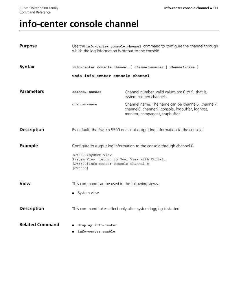
3Com Switch 5500 Family info-center console channel ● 611 Command Reference
info-center console channel
Purpose Use the info-center console channel command to configure the channel through which the log information is output to the console.
Syntax info-center console channel { channel-number | channel-name }
undo info-center console channel
Parameters channel-number Channel number. Valid values are 0 to 9, that is, system has ten channels.
channel-name Channel name. The name can be channel6, channel7, channel8, channel9, console, logbuffer, loghost, monitor, snmpagent, trapbuffer.
Description By default, the Switch 5500 does not output log information to the console.
Example Configure to output log information to the console through channel 0.
<SW5500>system-viewSystem View: return to User View with Ctrl+Z.[SW5500]info-center console channel 0[SW5500]
View This command can be used in the following views:
■ System view
Description This command takes effect only after system logging is started.
Related Command ■ display info-center
■ info-center enable

612 ● info-center enable 3Com Switch 5500 Family Command Reference
info-center enable
Purpose Use the info-center enable command to enable the system log function.
Use the undo info-center enable command to disable system log function.
Syntax info-center enable
undo info-center enable
Parameters None
Default By default, system log function is enabled.
Example Enable the system log function.
<SW5500>system-viewSystem View: return to User View with Ctrl+Z.[SW5500]info-center enable% Information center is enabled[SW5500]
View This command can be used in the following views:
■ System view
Description Only after the system log function is enabled can the system output the log information to the info-center loghost and console.
Related Commands ■ display info-center
■ info-center console channel
■ info-center logbuffer
■ info-center loghost
■ info-center monitor channel

3Com Switch 5500 Family info-center logbuffer ● 613 Command Reference
info-center logbuffer
Purpose Use the info-center logbuffer command to configure output information to the memory buffer.
Use the undo info-center logbuffer command to cancel the information output to buffer.
Syntax info-center logbuffer [ channel { channel-number | channel-name } | size buffersize ]
undo info-center logbuffer [ channel | size ]
Parameters channel Configures the channel to output information to buffer.
channel-number Channel number. Valid values are 0 to 9, that is, system has ten channels.
channel-name Channel name. Valid values are channel6, channel7, channel8, channel9, console, logbuffer, loghost, monitor, snmpagent, and trapbuffer.
size Configures the size of buffer.
buffersize Size of buffer (number of messages that can be kept); If not specified, the default size of the buffer is 512.
Example Send log information to buffer and sets the size of buffer as 50.
<SW5500>system-viewSystem View: return to User View with Ctrl+Z.[SW5500]info-center logbuffer 50[SW5500]
View This command can be used in the following views:
■ System view
Description This command takes effect only after system logging is enabled.
Related Command ■ info-center enable
■ display info-center

614 ● info-center loghost 3Com Switch 5500 Family Command Reference
info-center loghost
Purpose Use the info-center loghost command to set the IP address of the info-center loghost to send information to it.
Use the undo info-center loghost command to cancel output to info-center loghost.
Syntax info-center loghost host-ip-addr [ channel { channel-number | channel-name} | facility local-number | language { chinese | english } ]
undo info-center loghost
Parameters host-ip-addr IP address of info-center loghost.
channel Configures information channel of the info-center loghost.
channel-number Channel number. Valid values are 0 to 9, that is, the system has ten channels.
channel-name Channel name. Valid values are channel6, channel7, channel8, channel9, console, logbuffer, loghost, monitor, snmpagent, and trapbuffer.
facility Configures the recording tool of info-center loghost.
local-number Record tool of info-center loghost. Valid values are local0 to local7.
language Sets the logging language.
chinese, english Language used in log file.
Default By default, switches do not output information to info-center loghost.
Example Configure to send log information to the UNIX workstation at 202.38.160.1.
<SW5500>system-viewSystem View: return to User View with Ctrl+Z.[SW5500]info-center loghost 202.38.160.1[SW5500]
View This command can be used in the following views:
■ System view
Description This command takes effect only after the system logging is enabled.

3Com Switch 5500 Family info-center loghost ● 615 Command Reference
Related Commands ■ display info-center
■ info-center enable
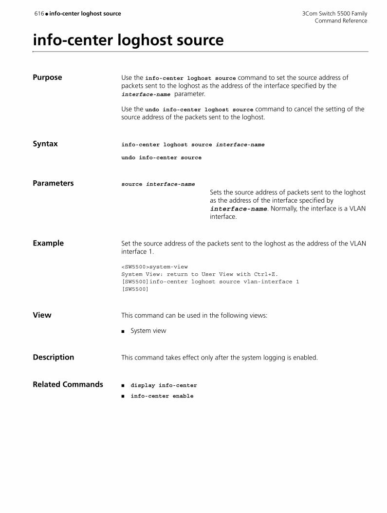
616 ● info-center loghost source 3Com Switch 5500 Family Command Reference
info-center loghost source
Purpose Use the info-center loghost source command to set the source address of packets sent to the loghost as the address of the interface specified by the interface-name parameter.
Use the undo info-center loghost source command to cancel the setting of the source address of the packets sent to the loghost.
Syntax info-center loghost source interface-name
undo info-center source
Parameters source interface-name Sets the source address of packets sent to the loghost as the address of the interface specified by interface-name. Normally, the interface is a VLAN interface.
Example Set the source address of the packets sent to the loghost as the address of the VLAN interface 1.
<SW5500>system-viewSystem View: return to User View with Ctrl+Z.[SW5500]info-center loghost source vlan-interface 1[SW5500]
View This command can be used in the following views:
■ System view
Description This command takes effect only after the system logging is enabled.
Related Commands ■ display info-center
■ info-center enable

3Com Switch 5500 Family info-center monitor channel ● 617 Command Reference
info-center monitor channel
Purpose Use the info-center monitor channel command to set the channel to output the log information to the user terminal.
Use undo info-center monitor channel command to restore the channel to output the log information to the user terminal to the default value.
Syntax info-center monitor channel { channel-number | channel-name }
undo info-center monitor channel
Parameters channel-number Channel number. Valid values are 0 to 9, that is, the system has ten channels.
channel-name Channel name. Valid values are channel6, channel7, channel8, channel9, console, logbuffer, loghost, monitor, snmpagent, and trapbuffer.
Default By default, switches do not output log information to user terminal.
Example Configure channel 0 to output log information to user terminal.
<SW5500>system-viewSystem View: return to User View with Ctrl+Z.[SW5500]info-center monitor channel 0 [SW5500]
View This command can be used in the following views:
■ System view
Description This command takes effect only after system logging is started.
Related Commands ■ display info-center
■ info-center enable

618 ● info-center snmp channel 3Com Switch 5500 Family Command Reference
info-center snmp channel
Purpose Use the info-center snmp channel command to specify new channel for transmitting the SNMP information.
Use undo info-center snmp channel command to restore the channel for transmitting the SNMP information to default value.
Syntax info-center snmp channel { channel-number | channel-name }
undo info-center snmp channel
Parameters channel-number Channel number. Valid values are 0 to 9, that is, the system has ten channels. If not specified, the default is channel 5.
channel-name Channel name. Valid values are channel6, channel7, channel8, channel9, console, logbuffer, loghost, monitor, snmpagent, and trapbuffer.
Example Configure channel 6 as the SNMP information channel.
<SW5500>system-viewSystem View: return to User View with Ctrl+Z.[SW5500]info-center snmp channel 6[SW5500]
View This command can be used in the following views:
■ System view
Related Command display snmp
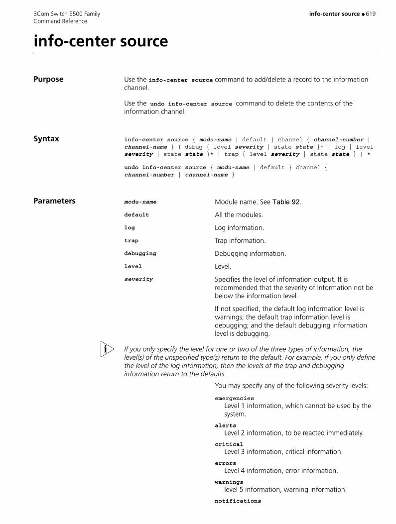
3Com Switch 5500 Family info-center source ● 619 Command Reference
info-center source
Purpose Use the info-center source command to add/delete a record to the information channel.
Use the undo info-center source command to delete the contents of the information channel.
Syntax info-center source { modu-name | default } channel { channel-number | channel-name } [ debug { level severity | state state }* | log { level severity | state state }* | trap { level severity | state state } ] *
undo info-center source { modu-name | default } channel { channel-number | channel-name }
Parameters modu-name Module name. See ������.
default All the modules.
log Log information.
trap Trap information.
debugging Debugging information.
level Level.
severity Specifies the level of information output. It is recommended that the severity of information not be below the information level.
If not specified, the default log information level is warnings; the default trap information level is debugging; and the default debugging information level is debugging.
If you only specify the level for one or two of the three types of information, the level(s) of the unspecified type(s) return to the default. For example, if you only define the level of the log information, then the levels of the trap and debugging information return to the defaults.
You may specify any of the following severity levels:
emergencies
Level 1 information, which cannot be used by the system.
alerts
Level 2 information, to be reacted immediately.
critical
Level 3 information, critical information.
errors
Level 4 information, error information.
warnings
level 5 information, warning information.
notifications
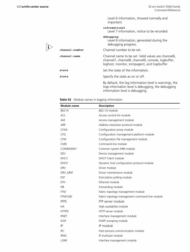
620 ● info-center source 3Com Switch 5500 Family Command Reference
Level 6 information, showed normally and important.
informational
Level 7 information, notice to be recorded.
debugging
Level 8 information, generated during the debugging progress.
channel-number Channel number to be set.
channel-name Channel name to be set. Valid values are channel6, channel7, channel8, channel9, console, logbuffer, loghost, monitor, snmpagent, and trapbuffer.
state Set the state of the information.
state Specify the state as on or off.
By default, the log information level is warnings, the trap information level is debugging, the debugging information level is debugging.
Table 92 Module names in logging information
Module name Description
8021X 802.1X module
ACL Access control list module
AM Access management module
ARP Address resolution protocol module
CFAX Configuration proxy module
CFG Configuration management platform module
CFM Configuration file management module
CMD Command line module
COMMONSY Common system MIB module
DEV Device management module
DHCC DHCP Client module
DHCP Dynamic host configuration protocol module
DRV Driver module
DRV_MNT Driver maintenance module
ESP End-station polling module
ETH Ethernet module
FIB Forwarding module
FTM Fabric topology management module
FTMCMD Fabric topology management command line module
FTPS FTP server module
HA High availability module
HTTPD HTTP server module
IFNET Interface management module
IGSP IGMP snooping module
IP IP module
IPC Inter-process communication module
IPMC IP multicast module
L2INF Interface management module

3Com Switch 5500 Family info-center source ● 621 Command Reference
Example Configure to enable the log information of STP module in SNMP channel and allows the output of the information with a level no higher than emergencies.
<SW5500>system-viewSystem View: return to User View with Ctrl+Z.[SW5500]info-center source stp channel snmpagent log level emergencies[SW5500]
View This command can be used in the following views:
■ System view
Description For example, for the filter of IP module log output, you can configure to output the logs at a level higher than warnings to the log host and output those higher than informational to the log buffer. You can also configure to output the trap information on the IP module to a specified trap host.
The channels for filtering in all the directions are specified by this configuration command. All the information will be sent to the corresponding directions through
LACL LANswitch ACL module
LQOS LANswitch QoS module
LS Local server module
MPM Multicast port management module
NTP Network time protocol module
PPRDT Protocol packet redirection module
PTVL Driver port, VLAN (Port & VLAN) module
QACL QoS/ACL module
QOSF Qos profile module
RDS Radius module
RM Routing management
RMON Remote monitor module
RSA Revest, shamir and adleman encryption system
RTPRO Routing protocol
SHELL User interface
SNMP Simple network management protocol
SOCKET Socket
SSH Secure shell module
STP Spanning tree protocol module
SYSMIB System MIB module
TELNET Telnet module
UDPH UDP helper module
VFS Virtual file system module
VTY Virtual type terminal module
WCN Web management module
XM XModem module
Table 92 Module names in logging information (continued)
Module name Description

622 ● info-center source 3Com Switch 5500 Family Command Reference
the specified channels. You can configure the channels in the output direction, channel filter information, filtering and redirecting of all kinds of information.
At present, the system distributes an information channel in each output direction by default, shown as follows:
In addition, each information channel has a default record with the module name “all” and module number as 0xffff0000. However, for different information channel, the default log, trap and debugging settings in the records may be different with one another. Use default configuration record if a module does not have any specific configuration record in the channel.
Table 93 Information channel in each output direction by default
Output direction Information channel name
Console console
Monitor monitor
Info-center loghost loghost
Log buffer logbuffer
Trap buffer trapbuffer
snmp snmpagent
3Com Switch 5500 Family info-center switch-on ● 623 Command Reference
info-center switch-on
Purpose Use the info-center switch-on command to turn on the information synchronization switch of the specified switch.
Use the undo info-center switch-on command to turn off the information synchronization switch of the specified switch.
Syntax info-center switch-on { unit-id | master | all } [ debugging | logging | trapping ]*
undo info-center switch-on { unit-id | master | all } [ debugging | logging | trapping ]*
Parameters unit-id Unit ID of switch.
master Master switch of Fabric.
all All switches of Fabric.
debugging Debugging information.
logging Log information.
trapping Trap information.
Default By default, the debugging information synchronization switch on master unit is enabled, log information and trap information switches on master unit are disabled, all information synchronization switches on slave unit are disabled.
Example To turn on the trapping information synchronization switch of the unit 2, enter the following:
<SW5500>system-viewSystem View: return to User View with Ctrl+Z.[SW5500]info-center switch-on 2 trapping[SW5500]
View This command can be used in the following views:
■ System view
Description After the forming of a Fabric by switches that support the XRN, the log, debugging and trap information among the switches is synchronous. The synchronization process is as follows: each switch sends its own information to other switches in the Fabric and meantime receives the information from others, and then the switch updates the local information to ensure the information coincidence within the Fabric.

624 ● info-center switch-on 3Com Switch 5500 Family Command Reference
The switch provides command line to turn on/off the synchronization switch in every switch. If the synchronization switch of a switch is turned off, it does not send information to other switches but still receives information from others.
3Com Switch 5500 Family info-center synchronous ● 625 Command Reference
info-center synchronous
Purpose Use the info-center synchronous command to enable the synchronous information output function.
Use the undo info-center synchronous command to disable the synchronous information output function.
Syntax info-center synchronous
undo info-center synchronous
Parameters None
Default By default, the synchronous information output function is disabled.
Example Enable synchronous information output function.
<S5500> system-viewSystem View: return to User View with Ctrl+Z.[S5500] info-center synchronousCurrent IC terminal output sync is on
View This command can be used in the following views:
■ System view
Description While enabled, the synchronous information output function allows the system to display command line prompts and users’ input so far after each system output, helping users continue with their input.
Note:
� Use the info-center synchronous command to prevent users’ input from being interrupted by system output and to realize synchro-nous information output.
� It is recommended that you disable this function during debugging, as the info-center synchronous command produces unnecessary output by displaying command line prompts after each piece of debug-ging information.

626 ● info-center timestamp 3Com Switch 5500 Family Command Reference
info-center timestamp
Purpose Use the info-center timestamp command to configure the timestamp output format in debugging/trap information.
Use the undo info-center timestamp command to disable the output of timestamp field.
Syntax info-center timestamp { log | trap | debugging } { boot | date | none }
undo info-center timestamp { log | trap | debugging }
Parameters log Log information.
trap Trap information.
debugging Debugging information.
boot Time elapsing after system starts. Format: xxxxxx.yyyyyy, xxxxxx is the high 32 bits of the elapsed time (in milliseconds) after system starts, and yyyyyy is the low 32 bits.
date Current system date and time. It shows as yyyy/mm/dd-hh:mm:ss in Chinese environment and mm/dd/yyyy-hh:mm:ss in Western language environment.
None No timestamp format.
Default By default, datetime stamp is used.
Example Configure the debugging information timestamp format as boot.
<SW5500>system-viewSystem View: return to User View with Ctrl+Z.[SW5500]info-center timestamp debugging boot[SW5500]
View This command can be used in the following views:
■ System view

3Com Switch 5500 Family info-center timestamp loghost ● 627 Command Reference
info-center timestamp loghost
Purpose Use the info-center timestamp loghost command to set the format of time stamp to be sent to log host.
Use the undo info-center timestamp loghost command to restore to the default system format.
Syntax info-center timestamp loghost { date | no-year-date | none }
undo info-center timestamp loghost
Parameters date The current system time and date, in the format of yyyy/mm/dd-hh:mm:ss. If no value is specified, the date time stamp is used as the default.
no-year-date The current system time and date without year information, in the format of yyyy/mm/dd-hh:mm:ss.
none Indicates that the output log information does not include time stamp information.
Example Set the time stamp to be sent to the log host as a format without year information.
<S5500> system-viewSystem View: return to User View with Ctrl+Z.[S5500] info-center timestamp loghost no-year-date
View This command can be used in the following views:
■ System view
628 ● info-center trapbuffer 3Com Switch 5500 Family Command Reference
info-center trapbuffer
Purpose Use the info-center trapbuffer command to output information to the trap buffer.
Use the undo info-center trapbuffer command to cancel output information to trap buffer.
Syntax info-center trapbuffer [ size buffersize ][ channel { channel-number | channel-name } ]
undo info-center trapbuffer
Parameters size Configures the size of the trap buffer. If not specified, the default is 256.
buffersize Size of trap buffer (numbers of messages).
channel Configures the channel to output information to trap buffer.
channel-number Channel number. Valid values are 0 to 9, that is, the system has ten channels.
channel-name Channel name.
Default By default, output information is transmitted to the trap buffer.
Example Send information to the trap buffer and sets the size of buffer as 30.
<SW5500>system-viewSystem View: return to User View with Ctrl+Z.[SW5500]info-center trapbuffer size 30[SW5500]
View This command can be used in the following views:
■ System view
Description This command takes effect only after system logging is enabled.
Related Commands ■ display info-center
■ info-center enable
3Com Switch 5500 Family instance ● 629 Command Reference
instance
Purpose Use the instance command to map specified VLANs to a specified spanning tree instance.
Use the undo instance command to remove the mappings from specified VLANs to a specified spanning tree instance.
Syntax instance instance-id vlan vlan-list
undo instance instance-id [ vlan vlan-list ]
Parameters instance-id ID of a spanning tree instance. Valid values are 0 to 16. A value of 0 specifies the CIST. If not specified, the default is 0.
vlan-list List of VLANs. You must provide this argument in the form of vlan-list = { vlan-id [ to vlan-id ] }&<1-10>, where &<1-10> means that you can provide up to 10 VLAN IDs/VLAN ID lists for this argument. Normally, a VLAN ID can be a number ranging from 1 to 4094. VLANs with their IDs beyond this range (if the switch supports this kind VLAN IDs), such as VLAN 4095 and VLAN 4096, can only be mapped to the CIST (spanning tree instance 0).
Example Map VLAN 2 to spanning tree instance 1.
<S5500> system-view System View: return to User View with Ctrl+Z.[S5500] stp region-configuration [S5500-mst-region] instance 1 vlan 2
View This command can be used in the following views:
■ MST Region view
Description When using the undo instance, the specified VLANs will then be mapped to the CIST (spanning tree instance 0) again. If you specify no VLAN in the undo instance command, all VLANs that are mapped to the specified spanning tree instance are mapped to the CIST again.
In MSTP, VLAN-to-spanning tree instance mappings are recorded in VLAN mapping tables. You can use the instance command to configure the VLAN mapping tables, that is, map VLANs to different spanning tree instances.
A VLAN cannot be mapped to multiple spanning tree instances. A VLAN-to-spanning tree instance mapping is automatically removed if you map the VLAN to another spanning tree instance.

630 ● instance 3Com Switch 5500 Family Command Reference
Related Commands ■ active region-configuration
■ check region-configuration
■ region-name
■ revision-level
■ vlan-mapping modulo

3Com Switch 5500 Family interface ● 631 Command Reference
interface
Purpose Use the command interface interface_type interface_number to enter the interface of the specified port.
Syntax interface interface_type interface_num | interface_name
Parameters interface_type Specifies the interface type. The interface type can be either Aux, Ethernet, GigabitEthernet, NULL, Vlan-interface.
interface_number Specifies the interface number in the format unit-number/0/port-number.
Specifies the unit number. Valid values are 1 to 8.
Specifies the port number. Valid values are 1 to 28 or 1 to 52, depending on the number of ports you have on your unit.
You can use the interface_name at this command. This consists of the interface_type and the interface_number combined as a single parameter. For example Ethernet1/0/1.
Example To enter the interface for port “Ethernet1/0/1”, enter the following:
<SW5500>system-viewSystem View: return to User View with Ctrl+Z.[SW5500]interface ethernet1/0/1[SW5500-ethernet1/0/1]
View This command can be used in the following views:
■ System view
Description If you want to configure the parameters of an Ethernet port, you must first use this command to enter the Ethernet port view.

632 ● interface VLAN-interface 3Com Switch 5500 Family Command Reference
interface VLAN-interface
Purpose Use the interface vlan-interface command to enter a VLAN interface view and use the related configuration commands.
Use the undo interface vlan-interface command to exit the current VLAN interface.
Syntax interface vlan-interface vlan_id
undo interface vlan-interface vlan_id
Parameters vlan_id The ID of the VLAN interface you want to configure. Valid values are 1 to 4094. If not specified, the default is VLAN1, which cannot be deleted.
Example To enter the interface view of VLAN1, enter the following:
<SW5500>system-viewSystem View: return to User View with Ctrl+Z.[SW5500] interface vlan-interface 1[SW5500-Vlan-interface1]
View This command can be used in the following views:
■ System view
Related Command display interface VLAN-interface
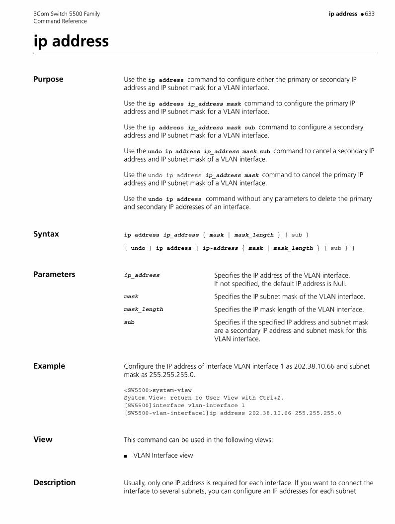
3Com Switch 5500 Family ip address ● 633 Command Reference
ip address
Purpose Use the ip address command to configure either the primary or secondary IP address and IP subnet mask for a VLAN interface.
Use the ip address ip_address mask command to configure the primary IP address and IP subnet mask for a VLAN interface.
Use the ip address ip_address mask sub command to configure a secondary address and IP subnet mask for a VLAN interface.
Use the undo ip address ip_address mask sub command to cancel a secondary IP address and IP subnet mask of a VLAN interface.
Use the undo ip address ip_address mask command to cancel the primary IP address and IP subnet mask of a VLAN interface.
Use the undo ip address command without any parameters to delete the primary and secondary IP addresses of an interface.
Syntax ip address ip_address { mask | mask_length } [ sub ]
[ undo ] ip address [ ip-address { mask | mask_length } [ sub ] ]
Parameters ip_address Specifies the IP address of the VLAN interface. If not specified, the default IP address is Null.
mask Specifies the IP subnet mask of the VLAN interface.
mask_length Specifies the IP mask length of the VLAN interface.
sub Specifies if the specified IP address and subnet mask are a secondary IP address and subnet mask for this VLAN interface.
Example Configure the IP address of interface VLAN interface 1 as 202.38.10.66 and subnet mask as 255.255.255.0.
<SW5500>system-viewSystem View: return to User View with Ctrl+Z.[SW5500]interface vlan-interface 1[SW5500-vlan-interface1]ip address 202.38.10.66 255.255.255.0
View This command can be used in the following views:
■ VLAN Interface view
Description Usually, only one IP address is required for each interface. If you want to connect the interface to several subnets, you can configure an IP addresses for each subnet.

634 ● ip address 3Com Switch 5500 Family Command Reference
Before you can cancel the primary IP address of an interface, you must cancel any secondary IP addresses.
The subnet address of an IP address can be identified by subnet mask. For instance, the IP address of an interface is 202.38.10.102, and the mask is 255.255.0.0. You can confirm that the subnet address is 202.38.0.0 by performing the logic operation “AND” on the IP address and mask.
Note that the VLAN interface cannot be configured with the secondary IP address if its IP address is set to be allocated by BOOTP or DHCP.
Related Command display interface VLAN-interface

3Com Switch 5500 Family ip address bootp-alloc ● 635 Command Reference
ip address bootp-alloc
Purpose Use the ip address bootp-alloc command to configure VLAN interface to obtain IP address using BOOTP.
Use the undo ip address bootp-alloc command to remove the configuration.
Syntax ip address bootp-alloc
undo ip address bootp-alloc
Parameters None
Default By default, the VLAN interface does not obtain an IP address using BOOTP.
Example To configure VLAN interface 1 to obtain IP address using BOOTP, enter the following:
<SW5500>system-viewSystem View: return to User View with Ctrl+Z.[SW5500]interface vlan-interface 1[SW5500-Vlan-interface1]ip address bootp-alloc
View This command can be used in the following views:
■ VLAN Interface view
Related Command display bootp client
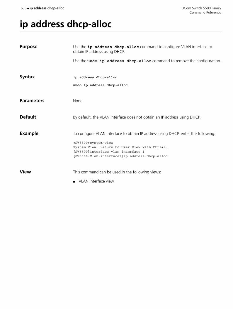
636 ● ip address dhcp-alloc 3Com Switch 5500 Family Command Reference
ip address dhcp-alloc
Purpose Use the ip address dhcp-alloc command to configure VLAN interface to obtain IP address using DHCP.
Use the undo ip address dhcp-alloc command to remove the configuration.
Syntax ip address dhcp-alloc
undo ip address dhcp-alloc
Parameters None
Default By default, the VLAN interface does not obtain an IP address using DHCP.
Example To configure VLAN interface to obtain IP address using DHCP, enter the following:
<SW5500>system-viewSystem View: return to User View with Ctrl+Z.[SW5500]interface vlan-interface 1[SW5500-Vlan-interface1]ip address dhcp-alloc
View This command can be used in the following views:
■ VLAN Interface view
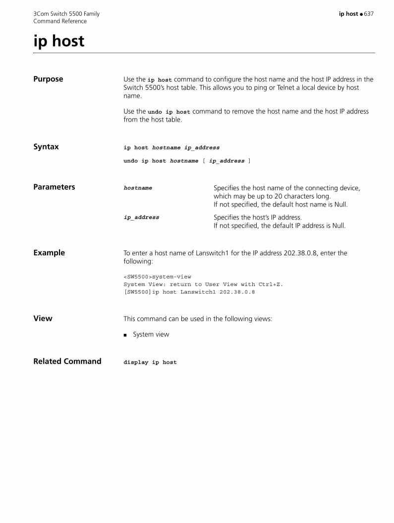
3Com Switch 5500 Family ip host ● 637 Command Reference
ip host
Purpose Use the ip host command to configure the host name and the host IP address in the Switch 5500’s host table. This allows you to ping or Telnet a local device by host name.
Use the undo ip host command to remove the host name and the host IP address from the host table.
Syntax ip host hostname ip_address
undo ip host hostname [ ip_address ]
Parameters hostname Specifies the host name of the connecting device, which may be up to 20 characters long. If not specified, the default host name is Null.
ip_address Specifies the host’s IP address. If not specified, the default IP address is Null.
Example To enter a host name of Lanswitch1 for the IP address 202.38.0.8, enter the following:
<SW5500>system-view System View: return to User View with Ctrl+Z. [SW5500]ip host Lanswitch1 202.38.0.8
View This command can be used in the following views:
■ System view
Related Command display ip host

638 ● ip http acl 3Com Switch 5500 Family Command Reference
ip http acl
Purpose Use the ip http acl command to call an ACL and perform ACL control over the WEB network management users.
Use the undo ip http acl command to cancel the ACL control over the WEB network management users.
Syntax ip http acl acl-number
undo ip http acl
Parameters acl-number Specifies a basic ACL. Valid values are a number from 2000 to 2999.
Example To perform ACL control over the WEB network management users, enter the following: (Suppose ACL 2020 has been defined.)
<SW5500>system-viewSystem View: return to User View with Ctrl+Z[SW5500]ip http acl 2020[SW5500]
View This command can be used in the following views:
■ User Interface view
Description This command calls numbered basic ACL only.
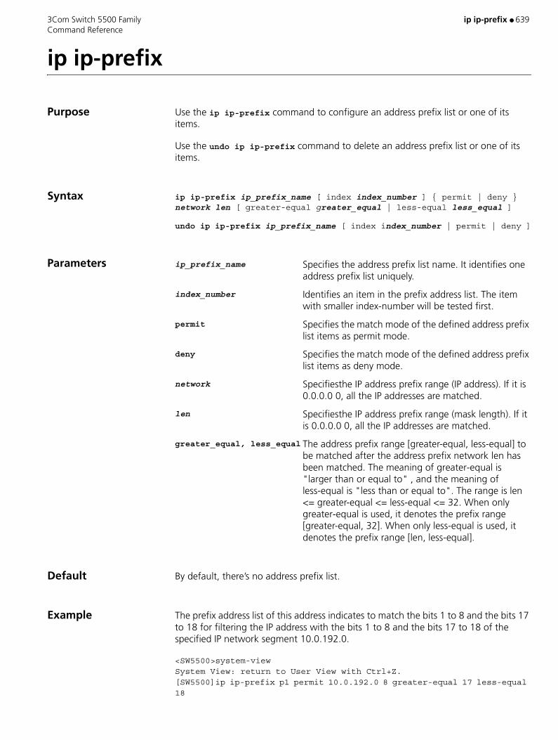
3Com Switch 5500 Family ip ip-prefix ● 639 Command Reference
ip ip-prefix
Purpose Use the ip ip-prefix command to configure an address prefix list or one of its items.
Use the undo ip ip-prefix command to delete an address prefix list or one of its items.
Syntax ip ip-prefix ip_prefix_name [ index index_number ] { permit | deny } network len [ greater-equal greater_equal | less-equal less_equal ]
undo ip ip-prefix ip_prefix_name [ index index_number | permit | deny ]
Parameters ip_prefix_name Specifies the address prefix list name. It identifies one address prefix list uniquely.
index_number Identifies an item in the prefix address list. The item with smaller index-number will be tested first.
permit Specifies the match mode of the defined address prefix list items as permit mode.
deny Specifies the match mode of the defined address prefix list items as deny mode.
network Specifiesthe IP address prefix range (IP address). If it is 0.0.0.0 0, all the IP addresses are matched.
len Specifiesthe IP address prefix range (mask length). If it is 0.0.0.0 0, all the IP addresses are matched.
greater_equal, less_equal The address prefix range [greater-equal, less-equal] to be matched after the address prefix network len has been matched. The meaning of greater-equal is "larger than or equal to" , and the meaning of less-equal is "less than or equal to". The range is len <= greater-equal <= less-equal <= 32. When only greater-equal is used, it denotes the prefix range [greater-equal, 32]. When only less-equal is used, it denotes the prefix range [len, less-equal].
Default By default, there’s no address prefix list.
Example The prefix address list of this address indicates to match the bits 1 to 8 and the bits 17 to 18 for filtering the IP address with the bits 1 to 8 and the bits 17 to 18 of the specified IP network segment 10.0.192.0.
<SW5500>system-viewSystem View: return to User View with Ctrl+Z.[SW5500]ip ip-prefix p1 permit 10.0.192.0 8 greater-equal 17 less-equal 18
640 ● ip ip-prefix 3Com Switch 5500 Family Command Reference
View This command can be used in the following views:
■ System view
Description The address prefix list is used for IP address filtering. An address prefix list may contain several items, and each item specifies one address prefix range. The inter-item filtering relation is "OR", that is, passing an item means passing the filtering of this address prefix list. Not passing the filtering of any item means not passing the filtration of this prefix address list.
The address prefix range may contain two parts, which are determined by len and [greater-equal, less-equal] respectively. If the prefix ranges of these two parts are both specified, the IP to be filtered must match the prefix ranges of these two parts.
If you specify network len as 0.0.0.0 0, it only matches the default route.

3Com Switch 5500 Family ip-pool ● 641 Command Reference
ip-pool
Purpose Use the ip-pool command to configure a private IP address range for cluster members on the switch to be set as the management device.
Use the undo ip-pool command to cancel the IP address configurations of the cluster.
Syntax ip-pool administrator-ip-address { ip-mask | ip-mask-length }
undo ip-pool
Parameters administrator-ip- address IP address of the management device of the cluster.
ip-mask Mask of the cluster IP address pool.
ip-mask-length Mask length of the cluster IP address pool.
Example Configure the IP address range of a cluster.
<S5500>system-viewSystem View: return to User View with Ctrl+Z.[S5500]cluster[S5500-cluster] ip-pool 10.200.0.1 20
View This command can be used in the following views:
■ Cluster view
Description Before setting up a cluster, the user should configure a private IP address pool for cluster member devices. When a candidate device is added, the management device will dynamically assign a private IP address, which can be used for communication inside the cluster. In this way, the user can use the management device to manage and maintain the member devices.
The commands can only be executed on a non-cluster-member switch. The IP address range of an existing cluster cannot be modified.

642 ● ip route-static 3Com Switch 5500 Family Command Reference
ip route-static
Purpose Use the ip route-static command to configure a static route, whose validity depends on detecting results as follows: valid when the detecting result is reachable or invalid when the detecting result is unreachable.
Use the undo ip route-static command to remove an existing static route.
Syntax ip route-static ip-address { mask | mask-length } next-hop [ preference preference-value ] [ reject | blackhole ] detect-group group-number
undo ip route-static ip-address { mask | mask-length } [ next-hop ] [ preference preference-value ]
Parameters ip-address IP address in dotted decimal notation.
mask Subnet mask.
mask-length Length of the subnet mask, that is, the number of successive bits in the subnet mask whose values are 1.
next-hop Next hop IP address in dotted decimal notation.
preference-value Preference value of the route. This argument ranges from 1 to 255.
reject Specifies the route to be unreachable. If you specify this keyword when executing this command, any packet destined for the specified IP address is discarded, and the system informs the source that the destination is unreachable.
blackhole Specifies the route to be a black hole. If you specify this keyword when executing this command, all outbound interfaces of the static route are the Null 0 interfaces regardless of the next hop. In addition, the system discards any packet transmitted along this route without informing the source.
group-number Detecting group number. Valid values are 1 to 50.
Example Configure a static route to 192.168.0.5/24 with 192.168.0.2 as the next hop. The route is to be enabled when the result of detecting group 10 is reachable.
<S5500> system-viewSystem View: return to User View with Ctrl+Z.[S5500] ip route-static 192.168.0.5 24 192.168.0.2 detect-group 10
View This command can be used in the following views:
■ System view

3Com Switch 5500 Family jumboframe enable ● 643 Command Reference
jumboframe enable
Purpose Use the jumboframe enable command to allow jumbo frames to pass through the specified Ethernet port.
Use the undo jumboframe enable command to prevent jumbo frames from passing through an Ethernet port.
Syntax jumboframe enable
undo jumboframe enable
Parameters None
Example Allow jumbo frames to pass through Ethernet port 1/0/1.
<SW5500>system-viewSystem View: return to User View with Ctrl+Z.[SW5500]interface ethernet 1/0/1[SW5500-Ethernet1/0/1]jumboframe enable [SW5500-Ethernet1/0/1]
View This command can be used in the following views:
■ Ethernet Port view
Description If using the 3comoscfg.def default file, jumbo frame support is disabled on all ports. When it is enabled, frames between 1522 bytes and 9216 bytes are permitted.
Only the Switch 5500-EI supports the jumboframe command.
644 ● key 3Com Switch 5500 Family Command Reference
key
Purpose Use the key command to configure a shared key for HWTACACS authentication, authorization or accounting.
Use the undo key command to delete the configuration.
Syntax key { accounting | authentication | authorization } string
undo key { accounting | authentication | authorization } string
Parameters accounting Shared key of the accounting server.
authentication Shared key of the authentication server.
authorization Shared key of the authorization server.
string The name of the shared key, comprised of a string up to 16 characters excluding the characters “?”.
Example Use “hello” as the shared key for HWTACACS accounting.
[S5500] hwtacacs scheme test1[S5500-hwtacacs-test1] key accounting hello
View This command can be used in the following views:
■ HWTACACS view
Description By default, no key is set.
The HWTACACS client (the switch system) and HWTACACS server use MD5 algorithm to encrypt the exchanged packets. The two ends verify packets using a shared key. Only when the same key is used can both ends accept the packets from each other and give responses. So it is necessary to ensure that the same key is set on the switch and the HWTACACS server. If the authentication/authorization and accounting are performed on two server devices with different shared keys, you must set one shared key for each.
Related Command display hwtacacs
3Com Switch 5500 Family lacp enable ● 645 Command Reference
lacp enable
Purpose Use the lacp enable command to enable LACP.
Use the undo lacp enable command to disable LACP.
Syntax lacp enable
undo lacp enable
Parameters None
Example To enable LACP at Ethernet1/0/1, enter the following:
<SW5500>system-viewSystem View: return to User View with Ctrl+Z.[SW5500]interface ethernet 1/0/1[SW5500-Ethernet1/0/1]lacp enable[SW5500-Ethernet1/0/1]
View This command can be used in the following views:
■ Ethernet Port view
Description The Switch will select the lowest port number as the master port for the link aggregation. This applies to all types of link aggregation. If the aggregation spans a stack of units (only available on the Switch 5500-EI) and the same ports are used, the unit number will be the tie-breaker. For example, 1/0/1 and 2/0/1 are in an aggregation. Port 1/0/1 will be the master port.
646 ● lacp port-priority 3Com Switch 5500 Family Command Reference
lacp port-priority
Purpose Use the lacp port priority command to configure port priority value.
Use the undo lacp port-priority command to restore the default value.
Syntax lacp port-priority port-priority-value
undo lacp port-priority
Parameters port-priority-value Port priority. Valid values are 0 to 65535. If not specified, the default is 32768.
Example To set port priority as 64, enter the following:
<SW5500>system-viewSystem View: return to User View with Ctrl+Z.[SW5500]interface ethernet 1/0/1[SW5500-Ethernet1/0/1]lacp port-priority 64[SW5500-Ethernet1/0/1]
View This command can be used in the following views:
■ Ethernet Port view
Related Commands ■ display link-aggregation interface
■ display link-aggregation verbose

3Com Switch 5500 Family lacp system-priority ● 647 Command Reference
lacp system-priority
Purpose Use the lacp system-priority command to configure system priority value.
Use the undo lacp system-priority command to restore the default value.
Syntax lacp system-priority system-priority-value
undo lacp system-priority
Parameters system-priority-value System priority. Valid values are 0 to 65535. If not specified, the default is 32768.
Example To set system priority as 64, enter the following:
<SW5500>system-viewSystem View: return to User View with Ctrl+Z.[SW5500]lacp system-priority 64[SW5500]
View This command can be used in the following views:
■ System view
Related Command display lacp system-id

648 ● language-mode 3Com Switch 5500 Family Command Reference
language-mode
Purpose Use the language-mode command to choose the language of the command line interface.
Syntax language-mode { chinese | english }
Parameters chinese Sets the language of the command line interface to Chinese.
english Sets the language of the command line interface to English. If not specified, the default is English.
Example To change the command line interface from English to Chinese, enter the following:
<SW5500-ui-aux0>language-mode chinese
View This command can be used in the following views:
■ User view
3Com Switch 5500 Family lcd ● 649 Command Reference
lcd
Purpose Use the lcd command to display local working path of FTP Client.
Syntax lcd
Parameters None
Example Show local working path.
<SW5500>ftp 1.1.1.1Trying ...Press CTRL+K to abortConnected.220 FTP service ready.User(none):hello331 Password required for hello.Password:230 User logged in[ftp]lcd% Local directory now flash:/temp [ftp]
View This command can be used in the following views:
■ FTP Client view
650 ● level 3Com Switch 5500 Family Command Reference
level
Purpose Use the level command to configure user priority level.
Use the undo level command to restore the default user priority level.
Syntax level level
undo level
Parameters level Specifies user priority level, an integer ranging from 0 to 3. If not specified, the default user priority level is 0.
Example To set the priority level of the user 3Com to 3, enter the following:
<SW5500>system-viewSystem View: return to User View with Ctrl+Z.[SW5500]local-user 3Com1[SW5500-luser-3Com1]level 3
View This command can be used in the following views:
■ Local User view
Description If the configured authentication mode is none authentication or password authentication, the command level that a user can access after login depends on the priority of user interface. In the case of authentication requiring both username and password, however, the accessible command level depends on user priority level.
Related Command local-user
3Com Switch 5500 Family line-rate ● 651 Command Reference
line-rate
Purpose Use the line-rate command, to limit the total rate of the packets received or delivered by interfaces.
Use the undo line-rate command, to cancel the configuration of limit rate at interfaces.
Syntax line-rate { inbound | outbound } target-rate
undo line-rate { inbound | outbound }
Parameters inbound LImits the rate of received packets.
outbound Limits the rate of delivered packets.
target-rate The total limited rate of the packets sent by interfaces. Unit in Kbps. The number input must be a multiple of 64. For 100 Mbps port, the range is from 64 to 99968; for 1000 Mbps port, the range is from 64 to 1000000.
Example Set the rate limitation of interface Ethernet1/0/1 to 128 kbps.
<SW5500>system-viewSystem View: return to User View with Ctrl+Z[SW5500]interface Ethernet 1/0/1[SW5500-Ethernet1/0/1] line-rate inbound 128[SW5500]line-rate outbound 128
View This command can be used in the following views:
■ Ethernet Port view
Description The granularity of line rate is 64 kbps.

652 ● link-aggregation group agg-id description 3Com Switch 5500 Family Command Reference
link-aggregation group agg-id description
Purpose Use the link-aggregation group agg-id description command to configure descriptor for an aggregation group.
Use the undo link-aggregation group agg-id description command to delete aggregation group descriptor.
Syntax link-aggregation group agg-id description alname
undo link-aggregation group agg-id description
Parameters agg-id Aggregation group ID. Valid values are 1 to 416.
alname Aggregation group name, consisting of a character string from 1 to 32 characters long.
Example To configure myal1 as the descriptor of aggregation group 22, enter the following:
<SW5500>system-viewSystem View: return to User View with Ctrl+Z.[SW5500]link-aggregation group 22 mode manual[SW5500]link-aggregation group 22 description myal1[SW5500]
View This command can be used in the following views:
■ System view
Related Command display link-aggregation verbose

3Com Switch 5500 Family link-aggregation group agg-id mode ● 653 Command Reference
link-aggregation group agg-id mode
Purpose Use the link-aggregation group agg-id mode command to create a manual or static aggregation group.
Use the undo link-aggregation group command to delete an aggregation group.
Syntax link-aggregation group agg-id mode { manual | static }
undo link-aggregation group agg-id
Parameters agg-id Aggregation group ID. Valid values are 1 to 416.
manual Manual aggregation group.
static Static aggregation group.
Example To create manual aggregation group 22, enter the following:
<SW5500>system-viewSystem View: return to User View with Ctrl+Z.[SW5500]link-aggregation group 22 mode manual
View This command can be used in the following views:
■ System view
Description The Switch will select the lowest port number as the master port for the link aggregation. This applies to all types of link aggregation. If the aggregation spans a stack of units (only available on the Switch 5500-EI) and the same ports are used, the unit number will be the tie-breaker. For example, 1/0/1 and 2/0/1 are in an aggregation. Port 1/0/1 will be the master port.
A manual or static aggregation group can have up to eight ports. You can use the link-aggregation group agg-id mode command to change an existing dynamic aggregation group into a manual or static one. If the port number in a group exceeds eight, this operation fails and the system prompts you about the configuration failure.
Related Command display link-aggregation summary
654 ● local-server 3Com Switch 5500 Family Command Reference
local-server
Purpose Use the local-server command to configure the parameters of local RADIUS server.
Use the undo local-server command to cancel a local RADIUS server.
Syntax local-server nas-ip ip-address key password
undo local-server nas-ip ip-address
Parameters nas-ip ip-address Set NAS-IP address of access server. ip-address is expressed in the format of dotted decimal. If not specified, the default local server with the NAS-IP address of 127.0.0.1 is used.
key password Set password of logon user. password is a character string up to 16 characters long.
Example To set the IP address of local RADIUS authentication server to 10.110.1.2 and the password to 3Com, enter the following:
<SW5500>system-viewSystem View: return to User View with Ctrl+Z.[SW5500]local-server nas-ip 10.110.1.2 key 3Com
View This command can be used in the following views:
■ System view
Description RADIUS service, which adopts authentication/authorization/accounting servers to manage users, is widely used in the Switch 5500. Besides, local authentication/authorization service is also used in these products and it is called local RADIUS function, that is, realize basic RADIUS function on the Switch.
When using local RADIUS server function, remember the number of the UDP port used for authentication is 1645 and that for accounting is 1646.
The password configured by this command must be the same as that of the RADIUS authentication/authorization packet configured by the command key authentication in the RADIUS Scheme View.
The Switch 5500 Series supports up to 16 local RADIUS authentication servers.
Related Commands ■ key
■ radius-scheme
■ state
3Com Switch 5500 Family local-user ● 655 Command Reference
local-user
Purpose Use the local-user command to add a local user and enter local user view.
Use the undo local-user command to delete the specified local user(s).
Syntax local-user user-name
undo local-user { user-name | all [ service-type { telnet | ftp | lan-access | ssh | terminal } ] }
Parameters user-name Local user name, a character string of no more than 80 characters. This string cannot contain the following characters: /:*?<>. It can contain no more than one "@" character; the pure user name (the part before "@", that is, the user ID) cannot be longer than 55 characters. The user name is case-insensitive; that is, the system considers “UserA” and “usera” the same user.
service-type Specifies a user type. You can specify one of the following user types: telnet, ftp, lan-access (this type of users are mainly Ethernet access users, for example, 802.1x users), ssh, and terminal (this type of users can use terminal service, that is, the users can log into the switch through Console port, AUX port, or Asynchronous serial port).
all Specifies all users.
Example Add a local user named hello1.
<S5500> sysSystem View: return to User View with Ctrl+Z.[S5500] local-user hello1[S5500-luser-hello1]
View This command can be used in the following views:
■ System view
656 ● local-user password-display mode 3Com Switch 5500 Family Command Reference
local-user password-display mode
Purpose Use the local-user password-display-mode command to set the password display mode to be used when the switch displays the local users.
Use the undo local-user password-display-mode command to restore the default password display mode.
Syntax local-user password-display-mode { auto | cipher-force }
undo local-user password-display-mode
Parameters auto Specifies to display passwords in the modes adopted when the passwords are set. If a password is set in cipher mode, the password will be displayed in cipher text; or else, the password will be displayed in plain text. If not specified, the default password display mode of local users is auto.
cipher-force Specifies to display passwords in cipher text forcibly.
Example Set the password display mode to be used when the switch displays local users to cipher-force.
[S5500] local-user password-display-mode cipher-force
View This command can be used in the following views:
■ System view
Description If the cipher-force mode is adopted, the passwords will be displayed in cipher text even though the password command is used to specify the password display mode to simple.
3Com Switch 5500 Family lock ● 657 Command Reference
lock
Purpose Use the lock command to lock the current user interface and prevent unauthorized users from accessing it.
Syntax lock
Parameters None
Example To lock the current user interface, enter the following:
<SW5500>lockPassword: xxxxAgain: xxxx
View This command can be used in the following views:
■ User view
Description An authorized user must enter a valid password to access the interface.
658 ● logging-host 3Com Switch 5500 Family Command Reference
logging-host
Purpose Use the logging-host command to configure a public logging host on the management device for member devices.
Use the undo logging-host command to cancel the logging host configuration.
Syntax logging-host ip-address
undo logging-host
Parameters ip-address IP address of the logging host configured for the cluster.
Default By default, no public logging host is configured.
Example Configure the IP address of the logging host on the management device.
<aaa_0.S5500>system-viewSystem View: return to User View with Ctrl+Z.[aaa_0.S5500]cluster[aaa_0.S5500-cluster] logging-host 10.10.10.9
View This command can be used in the following views:
■ Cluster view
Description Only after you assign an IP address for the logging host of the cluster, member devices can send log information to the logging host through the management device.

3Com Switch 5500 Family loopback ● 659 Command Reference
loopback
Purpose Use the loopback command to configure the Ethernet port to perform the loopback test to check if the Ethernet port works normally.
Syntax loopback { external | internal }
Parameters external External loop test.
internal Internal loop test.
Default The loop test will finish automatically after being performed for a while.
Example To perform the internal loop test for Ethernet1/0/1, enter the following:
<SW5500>system-viewSystem View: return to User View with Ctrl+Z.[SW5500]interface ethernet 1/0/1[SW5500-Ethernet1/0/1]loopback internal#Apr 2 02:46:02:29 2000 SW5500 L2INF/2/PORT LINK STATUS CHANGE:- 1 - Trap 1.3.6.1.6.3.1.1.5.4: portIndex is 4227626, ifAdminStatus is 1, ifOperStatus is 1
%Apr 2 02:46:02:225 2000 SW5500 L2INF/5/PORT LINK STATUS CHANGE:- 1 - Ethernet1/0/1: is UP
%Apr 2 02:46:02:342 2000 SW5500 STP/2/SPEED:- 1 -Ethernet1/0/1’s speed changed!#Apr 2 02:46:02:521 2000 SW5500 L2INF/2/PORT LINK STATUS CHANGE:- 1 -Trap 1.3.6.1.6.3.1.1.5.3: portIndex is 4227626, ifAdminStatus is 1, ifOperStatus is 2
Loop internal succeeded.[SW5500-Ethernet1/0/1][SW5500-Ethernet1/0/1]loopback internal
View This command can be used in the following views:
■ Ethernet Port view
Description By default, the Ethernet port will not perform the loopback test.

660 ● loopback-detection control enable 3Com Switch 5500 Family Command Reference
loopback-detection control enable
Purpose Use the loopback-detection control enable command to enable loopback detection and control function for Trunk ports and Hybrid ports.
Use the undo loopback-detection control enable command to disable loopback detection and control function for Trunk ports and Hybrid ports.
Syntax loopback-detection control enable
undo loopback-detection control enable
Parameters None
Default By default, the loopback detection and control function is disabled for both the Trunk and Hybrid ports.
Example Enable the loopback detection and control function for Trunk port Ethernet1/0/1.
<S5500> system-viewSystem View: return to User View with Ctrl+Z.[S5500] loopback-detection enable[S5500] interface ethernet1/0/1[S5500-Ethernet1/0/1] loopback-detection enable[S5500-Ethernet1/0/1] loopback-detection control enable
View This command can be used in the following views:
■ Ethernet Port view
Description ■ When the loopback detection and control function is enabled, if system detects loopback for a port, it will shut down that port, send a Trap message to the terminal, and delete the corresponding MAC address forwarding entry.
■ When the loopback detection and control function is disabled, if system detects loopback for a port, it will only send a Trap message to the terminal and the port will still work under normal working state.
CAUTION:
The above command does not work for Access ports as, as the loopback detection function is always enabled for Access ports.
3Com Switch 5500 Family loopback-detection enable ● 661 Command Reference
loopback-detection enable
Purpose Use the loopback-detection enable command to enable the loopback detection function globally or for a specific port.
Use the undo loopback-detection enable command to disable the loopback detection function globally or for a specific port.
Syntax loopback-detection enable
undo loopback-detection enable
Parameters None
Default By default, the loopback detection function is disabled.
Example Enable the loopback detection function for Ethernet1/0/1 port.
<S5500> system-viewSystem View: return to User View with Ctrl+Z.[S5500] loopback-detection enable[S5500] interface ethernet1/0/1[S5500-Ethernet1/0/1] loopback-detection enable
View This command can be used in the following views:
■ System view
■ Ethernet Port view
Description CAUTION:
■ Loopback detection for a port is enabled only when the loopback-detection enable command is enabled under both system view and port view.
■ When the undo loopback-detection enable command is used under system view, the loopback detection function will be disabled for all ports.
■ For Access port: If system detects loopback for a port, it will shut down that port, send a Trap message to the terminal, and delete the corresponding MAC address forwarding entry.
■ For Trunk ports and Hybrid ports: If system detects loopback for a port, it will send a Trap message to the terminal. If the loopback detection and control function for that port is enabled at the same time, the system will then shut down the given port, send a Trap message to the terminal, and delete the corresponding MAC address forwarding entry.

662 ● loopback-detection enable 3Com Switch 5500 Family Command Reference
Related Command loopback-detection control enable

3Com Switch 5500 Family loopback-detection interval-time ● 663 Command Reference
loopback-detection interval-time
Purpose Use the loopback-detection interval-time command to set the time interval for detecting the external loopback for a port.
Use the undo loopback-detection interval-time command to restore the time interval to default value.
Syntax loopback-detection interval-time time
undo loopback-detection interval-time
Parameters Time Time interval for detecting the external loopback for a port, in seconds. Valid values are 5 to 300. If not specified, the default is 30 seconds.
Example Set the time interval for regular external loopback detection to 10 seconds.
<S5500> system-viewSystem View: return to User View with Ctrl+Z.[S5500] loopback-detection interval-time 10
View This command can be used in the following views:
■ System view
Related Command display loopback-detection

664 ● loopback-detection per-vlan enable 3Com Switch 5500 Family Command Reference
loopback-detection per-vlan enable
Purpose Use the loopback-detection per-vlan enable command to enable loopback detection function for all VLANs with Trunk ports and Hybrid ports.
Use the undo loopback-detection per-vlan enable command to enable loopback detection function only for the default VLANs with Trunk ports and Hybrid ports.
Syntax loopback-detection per-vlan enable
undo loopback-detection per-vlan enable
Parameters None
Default By default, system detects loopback only for the default VLANs with Trunk ports and Hybrid ports.
Example Configure system to detect the loopback for all VLANs with Trunk port Ethernet1/0/1.
<S5500> system-viewSystem View: return to User View with Ctrl+Z.[S5500] interface ethernet1/0/1[S5500-Ethernet1/0/1] loopback-detection per-vlan enable
View This command can be used in the following views:
■ Ethernet Port view
Description CAUTION:
The above command does not work for Access ports.
3Com Switch 5500 Family ls ● 665 Command Reference
ls
Purpose Use the ls command to display the files in the specified directory.
Syntax ls [ remote-path ]
Parameters remote-path Name of the intended directory.
Example Display the files in directory flash:/.
sftp-client> ls flash:/-rwxrwxrwx 1 noone nogroup 1759 Aug 23 06:52 vrpcfg.cfg-rwxrwxrwx 1 noone nogroup 225 Aug 24 08:01 pubkey2-rwxrwxrwx 1 noone nogroup 283 Aug 24 07:39 pubkey1-rwxrwxrwx 1 noone nogroup 225 Sep 28 08:28 pub1drwxrwxrwx 1 noone nogroup 0 Sep 28 08:24 new1drwxrwxrwx 1 noone nogroup 0 Sep 28 08:18 new2-rwxrwxrwx 1 noone nogroup 225 Sep 28 08:30 pub2
View This command can be used in the following views:
■ SFTP Client view
Description If the remote-path argument is not specified, the files in the current directory are displayed.
This command has the same function as the dir command.

666 ● mac-address 3Com Switch 5500 Family Command Reference
mac-address
Purpose Use the mac-address command to add/modify the MAC address table entry.
Use the undo mac-address command to delete MAC address table entry.
Syntax mac-address { static | dynamic | blackhole } mac-address interface { interface-name | interface-type interface-num } vlan vlan-id
undo mac-address [ { static | dynamic | blackhole } mac-address interface {interface-name | interface-type interface-num ] vlan vlan-id ]
Parameters static Static table entry, lost after resetting switch.
dynamic Dynamic table entry, which will be aged.
blackhole Blackhole table entry, the packet with this destination MAC address will be discarded.
mac-addr Specifies the MAC address.
interface-type Specifies the interface type.
interface-num Specifies the interface number.
interface-name Specifies the interface name.
vlan-id Specifies the VLAN ID.
Example Configure the port number corresponding to the MAC address 00e0-fc01-0101 as Ethernet1/0/1 in the address table, and sets this entry as static entry.
<SW5500>sysSystem View: return to User View with Ctrl+Z.[SW5500]mac-address static 00e0-fc01-0101 interface Ethernet 1/0/1 vlan 2
View This command can be used in the following views:
■ System view
Description If the input address has been existing in the address table, the original entry will be modified. That is, replace the interface pointed by this address with the new interface and the entry attribute with the new attribute (dynamic entry and static entry).
All the (MAC unicast) addresses on a certain interface can be deleted. User can choose to delete any of the following addresses: address learned by system automatically, dynamic address configured by user, static address configured by user.
Related Command display mac-address
3Com Switch 5500 Family mac-address max-mac-count ● 667 Command Reference
mac-address max-mac-count
Purpose Use the mac-address max-mac-count command to configure the maximum number of MAC addresses that can be learned by a specified Ethernet port.
Use the undo mac-address-table max-mac-count command to cancel the maximum limit on the number of MAC addresses learned by an Ethernet port.
Syntax mac-address max-mac-count count
undo mac-address max-mac-count
Parameters count The number of MAC addresses a port can learn. Valid values are 0 to 32768. A value of 0 means that the port is not allowed to learn MAC addresses.�If no maximum limit is set, the MAC address table controls the number of MAC addresses a port can learn.
Example To configure the port “Ethernet 1/0/3” to learn at most 600 MAC addresses, enter the following:
<SW5500>sysSystem View: return to User View with Ctrl+Z.[SW5500]inteface Ethernet 1/0/3[SW5500-Ethernet1/0/3]mac-address max-mac-count 600
To cancel the maximum limit on the number of MAC addresses learned by the port “Ethernet1/0/3”, enter the following:
<SW5500>sysSystem View: return to User View with Ctrl+Z.[SW5500]inteface Ethernet 1/0/3[SW5500-Ethernet1/0/3]undo mac-address max-mac-count
View This command can be used in the following views:
■ Ethernet Port view
Description The port stops learning MAC addresses when the specified limit is reached.
Related Commands ■ mac-address
■ mac-address timer

668 ● mac-address multicast interface vlan 3Com Switch 5500 Family Command Reference
mac-address multicast interface vlan
Purpose Use the mac-address multicast command to add a multicast MAC address entry.
Use the undo mac-address multicast command to remove a multicast MAC address entry.
Syntax mac-address multicast mac-address interface interface-list vlan vlan-id
undo mac-address multicast [ mac-address [ interface interface-list ] vlan vlan-id ]
Parameters mac-address Multicast MAC address.
interface-list Forward port list, in the format of { { interface-type interface-num | interface-name } [ to { interface-type interface-num | interface-name } ] }&<1-10>. Where, interface-type and interface-num are the type and number of a port, interface-name is the name of a port, and &<1-10> means you can specify up to 10 ports/port ranges. For the value ranges of the three arguments, refer to the command parameter description in the Port Configuration module of this document.
vlan-id VLAN ID.
Example Add a multicast MAC address entry for VLAN 1, with the multicast MAC address 0100-5e0a-0805 and forward port Ethernet 1/0/1.
<S5500> system-viewSystem View: return to User View with Ctrl+Z.[S5500] mac-address multicast 0100-5e0a-0805 interface Ethernet 1/0/1 vlan 1
View This command can be used in the following views:
■ System view
Description A multicast address entry contains the following information: multicast MAC address, Forward port, and VLAN ID.
Related Command display mac-address multicast static
3Com Switch 5500 Family mac-address multicast vlan ● 669 Command Reference
mac-address multicast vlan
Purpose Use the mac-address multicast vlan command to add a multicast MAC address entry.
Use the undo mac-address multicast vlan command to remove a multicast MAC address entry.
Syntax mac-address multicast mac-address vlan vlan-id
undo mac-address multicast [ [ mac-address ] vlan vlan-id ]
Parameters mac-address Multicast MAC address.
vlan-id VLAN ID.
Example Add a multicast MAC address entry for VLAN 1, with the multicast MAC address 0100-1000-1000 and forward port Ethernet 1/0/1.
<S5500> system-viewSystem View: return to User View with Ctrl+Z.[S5500] interface Ethernet1/0/1[S5500-Ethernet1/0/1]mac-address multicast 0100-1000-1000 vlan 1
View This command can be used in the following views:
■ Ethernet Port view
Description A multicast MAC address entry contains a multicast MAC address, a VLAN ID, and some other information.
Related Command display mac-address multicast static
670 ● mac-address timer 3Com Switch 5500 Family Command Reference
mac-address timer
Purpose Use the mac-address timer command to configure the aging time of the Layer-2 dynamic address table entry.
Use the undo mac-address timer command to restore the default value.
Syntax mac-address timer { aging age | no-aging }
undo mac-address timer aging
Parameters aging age Specifies the aging time (measured in seconds) of the Layer-2 dynamic address table entry. Valid values are 10 to 1000000. If not specified, the default aging time is 300 seconds.
no-aging No aging time.
Example Configure the entry aging time of Layer-2 dynamic address table to be 500 seconds.
<SW5500>sysSystem View: return to User View with Ctrl+Z.[SW5500]mac-address timer aging 500
View This command can be used in the following views:
■ System view
Description Setting the aging time on the switch to be too long or too short will cause the switch to broadcast data packets without MAC addresses, this will affect the operational performance of the switch.
If the aging time is set too long, the switch will store out-of-date MAC address tables. This will consume MAC address table resources and the switch will not be able to update MAC address table according to the network change.
If aging time is set too short, the switch may delete valid MAC address table entries.

3Com Switch 5500 Family mac-authentication ● 671 Command Reference
mac-authentication
Purpose Use the mac-authentication command to enable centralized MAC address authentication globally (current device) or on specified ports.
Use the undo mac-authentication command to disable centralized MAC address authentication globally or on specified ports.
Syntax mac-authentication [ interface interface-list ]
undo mac-authentication [ interface interface-list ]
Parameters interface-list Lists of Ethernet ports. You can specify multiple Ethernet ports by providing this argument in the form of interface-list = { interface-type interface-number [ to interface-type interface-number ] } &<1-10>, where &<1-10> means that you can provide up to 10 port indexes/port index lists for this argument.
Default By default, centralized MAC address authentication is disabled both globally and on any port.
Example Enable centralized MAC address authentication on GigabitEthernet 1/0/1 port.
<S5500> system-view
System View: return to User View with Ctrl+Z.
[S5500] mac-authentication interface GigabitEthernet 1/0/1
Enable centralized MAC address authentication feature globally.
[S5500] mac-authentication
View This command can be used in the following views:
■ System view
■ Ethernet Port view
Description When being executed in system view, the mac-authentication command enables centralized MAC address authentication globally if you do not provide the interface-list argument, otherwise, the command enables centralized MAC address authentication on the specified ports. When being executed in Ethernet port view, the command enables centralized MAC address authentication on the current port only. In this case, the interface-list is unnecessary.
You can configure centralized MAC address authentication-related parameters no matter whether or not centralized MAC authentication is enabled. If you do not

672 ● mac-authentication 3Com Switch 5500 Family Command Reference
configure the parameters before enabling centralized MAC address authentication globally, the default parameters are adopted.
Note:
■ To make the configuration of port-based centralized MAC address authentication take effect, you must enable global centralized MAC address authentication globally besides enabling port-based centralized MAC address authentication.
■ For a port, the centralized MAC address authentication configuration and the maximum number of learned MAC addresses configuration are mutually exclusive. That is, if you enable the centralized MAC address authentication function for a port, the maximum number of learned MAC addresses configuration (see the mac-address max-mac-count command) is unavailable. And if you set the maximum number of learned MAC addresses, the centralized MAC address authentication configuration is unavailable.
3Com Switch 5500 Family mac-authentication authmode ● 673 Command Reference
mac-authentication authmode
Purpose Use the mac-authentication authmode command to set MAC address authentication mode.
Use the undo mac-authentication authmode command to cancel the configured MAC address authentication mode.
Syntax mac-authentication authmode { usernameasmacaddress | usernamefixed }
undo mac-authentication authmode
Parameters usernameasmacaddress Authenticates users in MAC address mode.
usernamefixed Authenticates users in fixed mode.
Default By default, a switch authenticates users in MAC address mode.
Example Configure to authenticate users in fixed mode.
<S5500> system-viewSystem View: return to User View with Ctrl+Z.[S5500] mac-authentication authmode usernamefixed
View This command can be used in the following views:
■ System view
Description Use the mac-authentication authmode command to set MAC address authentication mode.
Use the undo mac-authentication authmode command to cancel the configured MAC address authentication mode.
■ The usernameasmacaddress keyword specifies to authenticate users in MAC address mode. That is, the MAC address of a user is used as both the user name and password.
■ The usernamefixed keyword specifies to authenticate users in fixed mode, where you need to configure both user name and password separately.
674 ● mac-authentication authpassword 3Com Switch 5500 Family Command Reference
mac-authentication authpassword
Purpose Use the mac-authentication authpassword command to set a password when a switch authenticates users in fixed mode.
Use the undo mac-authentication authpassword command to remove the configured password.
Syntax mac-authentication authpassword password
undo mac-authentication authpassword
Parameters password Password for authentication, consisting of a character string from 1 to 63 characters long.
Default By default, no password is configured for the fixed mode of MAC address authentication.
Example Set the password to mac for fixed mode.
<S5500> system-viewSystem View: return to User View with Ctrl+Z.[S5500] mac-authentication authpassword mac
View This command can be used in the following views:
■ System view

3Com Switch 5500 Family mac-authentication authusername ● 675 Command Reference
mac-authentication authusername
Purpose Use the mac-authentication authusername command to set a user name when a switch authenticates users in fixed mode.
Use the undo mac-authentication authusername command to restore the default user name.
Syntax mac-authentication authusername username
undo mac-authentication authusername
Parameters username User name for authentication consisting of a character string from1 to 55 characters long. If not specified, the default user name is mac.
Example Set the user name to vipuser for fixed mode.
<S5500> system-viewSystem View: return to User View with Ctrl+Z.[S5500] mac-authentication authusername vipuser
Restore the default user name.
[S5500] undo mac-authentication authusername
View This command can be used in the following views:
■ System view
676 ● mac-authentication domain 3Com Switch 5500 Family Command Reference
mac-authentication domain
Purpose Use the mac-authentication domain command to configure an ISP domain for centralized MAC address authentication users.
Use the undo mac-authentication domain command to restore the default ISP domain.
Syntax mac-authentication domain isp-name
undo mac-authentication domain
Parameters isp-name ISP domain name consisting of a string up to 24 characters long. Note that this argument cannot contain “/”, “:”, “*”, “?”, “<”, and “>”.
Default By default, the domain for centralized MAC address authentication users is not configured.
Example Configure the domain for centralized MAC address authentication users to be Cams.
<S5500> system-viewSystem View: return to User View with Ctrl+Z.[S5500] mac-authentication domain Cams
View This command can be used in the following views:
■ System view

3Com Switch 5500 Family mac-authentication timer ● 677 Command Reference
mac-authentication timer
Purpose Use the mac-authentication timer command to set centralized MAC address authentication timers.
Use the undo mac-authentication timer command to restore the default centralized MAC address authentication timers.
Syntax mac-authentication timer { offline-detect offline-detect-value | quiet quiet-value | server-timeout server-timeout-value }
undo mac-authentication timer { offline-detect | quiet | server-timeout }
Parameters offline-detect offline-detect-value Sets the offline-detect timer (in seconds). This timer
sets the interval for a switch to test whether or not a user goes offline. Valid values for the offline-detect-value argument are 1 to 65,535. If not specified, the default is 300.
quiet quiet-value Specifies the quiet timer. If a user fails to pass the authentication performed by a switch, the switch stops authenticating users for a period specified by the quiet-value before it authenticates users again. Valid values for the quiet-value argument are 1 to 3600 (in seconds). If not specified, the default is 1.
server-timeout server-timeout-value Specifies the server-timeout timer. If the connection
between a switch and a RADIUS server times out when the switch authenticates a user on one of its ports, the switch turns down the user. Valid values for the server-timeout-value argument are 1 to 65,535 (in seconds). If not specified, the default is 100.
Example Set the server-timeout timer to 150 seconds.
<S5500> system-viewSystem View: return to User View with Ctrl+Z. [S5500] mac-authentication timer server-timeout 150
View This command can be used in the following views:
■ System view
Related Command display mac-authentication

678 ● management-vlan 3Com Switch 5500 Family Command Reference
management-vlan
Purpose Use the management-vlan command to specify the management VLAN on the switch.
Use the undo management-vlan command to restore the default management VLAN.
Syntax management-vlan vlan-id
undo management-vlan
Parameters vlanid ID of management VLAN.
Default By default, VLAN 1 is set as the management VLAN.
Example Specify VLAN 2 as the management VLAN of the current switch.
<S5500>system-viewSystem View: return to User View with Ctrl+Z.[S5500] management-vlan 2
View This command can be used in the following views:
■ System view
Description Follow these items when you configure the management VLAN:
■ The management VLAN specified for devices in the same cluster must be the same VLAN.
■ The management VLAN must be specified before the cluster is set up. You cannot change the management VLAN of an existing VLAN. If necessary, you can delete the cluster, re-specify the management VLAN and then re-create the cluster.

3Com Switch 5500 Family mdi ● 679 Command Reference
mdi
Purpose Use the mdi command to configure the network cable type for an Ethernet port.
Use the undo mdi command to restore the default type. By default, the network cable type is recognized automatically (the mdi auto command).
Syntax mdi { across | auto | normal }
undo mdi
Parameters across Configures the network cable type to cross-over cable. This option is not available on the Switch 5500.
auto Configures the use of either straight-through cable or cross-over cable.
normal Configures the network cable type to straight-through cable. This option is not available on the Switch 5500.
Example To configure the network cable type of port “Ethernet1/0/1” as cross-over cable, enter the following:
<SW5500>system-viewSystem View: return to User View with Ctrl+Z.[SW5500]interface ethernet 1/0/1[SW5500-Ethernet1/0/1]mdi across[SW5500-Ethernet1/0/1]
View This command can be used in the following views:
■ Ethernet Port view
Description Note: This command only has effect on 10/100BASE-T and 10/100/1000BASE-T ports. The Switch 5500 only supports auto (auto-sensing). If you enter another type, an error message displays.

680 ● memory auto-establish disable 3Com Switch 5500 Family Command Reference
memory auto-establish disable
Purpose Use the memory auto-establish disable command to disable the routing protocol connection that is forcibly disconnected to recover automatically when the idle memory of the Ethernet switch reaches this value.
Syntax memory auto-establish disable
Parameters None
Default By default, when the idle memory of the Ethernet switch recovers to a safety value, connections of all the routing protocols will always recover (when the idle memory of the Ethernet switch reduces to a lower limit, the connection will be disconnected forcibly).
Thus, connections of all the routing protocols will not recover when the idle memory of the Ethernet switch recovers to a safety value. In this case, you need to restart the routing protocol to recover the connections.
Example Disable memory resume of the current Ethernet switch and recover connections of all the protocols automatically.
<SW5500>system-viewSystem View: return to User View with Ctrl+Z.[SW5500]memory auto-establish disable
View This command can be used in the following views:
■ System view
Related Commands ■ display memory limit
■ memory auto-establish enable
■ memory { safety | limit }
3Com Switch 5500 Family memory auto-establish enable ● 681 Command Reference
memory auto-establish enable
Purpose Use the memory auto-establish enable command to allow the routing protocol connection that is forcibly disconnected to recover automatically when the idle memory of the Switch reaches this value.
Syntax memory auto-establish enable
Parameters None
Default By default, when the idle memory of the Switch recovers to a safety value, connections of all the routing protocols will always recover (when the idle memory of the Ethernet switch reduces to a lower limit, the connection will be disconnected forcibly).
Example Enable memory resume of the current Switch and recover connections of all the protocols automatically.
<SW5500>system-viewSystem View: return to User View with Ctrl+Z.[SW5500]memory auto-establish enable
View This command can be used in the following views:
■ System view
Related Commands ■ display memory limit
■ memory auto-establish disable
■ memory { safety | limit }
682 ● memory { safety | limit } 3Com Switch 5500 Family Command Reference
memory { safety | limit }
Purpose Use the memory command to configure the limit or safety of the Switch idle memory.
Use the memory limit limit_value command to configure the lower limit of the Switch idle memory.
Use the memory safety safety_value command to configure the safety value of the Switch idle memory.
Use the memory safety safety_value limit limit_value command to change both of the safety value and lower limit of the Switch idle memory.
Use the undo memory command to configure the safety value and the lower limit of the Switch idle memory to the default configuration.
Syntax memory { safety safety_value | limit limit_value }*
undo memory [ safety | limit ]
Parameters safety safety_value The safety value of the Switch idle memory, in Mbytes. Its range of valid values depends on the idle memory of the active Switch. If not specified, the default value is 4Mbytes.
limit limit_value The lower limit of the Switch idle memory, in Mbytes. Its range of valid values depends on the idle memory of the active Switch. If not specified, the default value is 2Mbytes.
Example Set the lower limit of the Switch idle memory to 1 Mbytes and the safety value to 3 Mbytes.
<SW5500>system-viewSystem View: return to User View with Ctrl+Z.[SW5500]memory safety 3 limit 1%Apr 2 01:43:35:678 2000 SW5500 RM/5/RTLOG:- 1 -Changed the system memory limit(5->1)/safety(6->3) successfully
View This command can be used in the following views:
■ System view
Description When the idle memory of the Switch is less than this limit, all the routing protocol connections will be disconnected forcibly. The limit_value in the command must be less than the current idle memory safety value or the configuration will fail.
If you use the memory auto-establish enable command (the default configuration), the routing protocol connection that is forcibly disconnected will automatically recover when the idle memory of the Switch reaches this value. The

3Com Switch 5500 Family memory { safety | limit } ● 683 Command Reference
safety_value in the command must be more than the current idle memory lower limit or the configuration will fail.
The safety_value must be more than the limit_value or the configuration will fail.
Related Commands ■ display memory limit
■ memory auto-establish disable
■ memory auto-establish enable
684 ● messenger 3Com Switch 5500 Family Command Reference
messenger
Purpose Use the messenger time command to enable or disable the messenger alert and configure the related parameters.
Use the undo messenger time command to restore messenger alert to default settings.
Syntax messenger time { enable limit interval | disable }
undo messenger time
Parameters limit Remaining-online-time threshold in minutes. Valid values are 1 to 60. When the remaining online time of a user is equal to this threshold, the Switch begins to send alert messages to the client.
interval The sending interval of alert messages in minutes. Valid values are of 5 to 60.
Example To configure to start the sending of alert messages when the user’s remaining online time is 30 minutes and send the messages at an interval of five minutes, enter the following:
<SW5500>system-viewSystem View: return to User View with Ctrl+Z.[SW5500]domain system[SW5500-isp-system]messenger time enable 30 5
View This command can be used in the following views:
■ ISP Domain view
Description By default, the messenger alert is disabled on the Switch.
This function allows the clients to inform the online users about their remaining online time through message alert dialog box.
The implementation of this function is as follows:
■ On the Switch, use the messenger time enable command to enable this function and to configure the remaining-online-time threshold (the limit argument) and the alert message interval.
■ If the threshold is reached, the Switch sends messages containing the user’s remaining online time to the client at the interval you configured.
■ The client keeps the user informed of the remaining online time through a message alert dialog box.

3Com Switch 5500 Family mirrored-to ● 685 Command Reference
mirrored-to
Purpose Use the mirrored-to command to enable ACL traffic identification and perform traffic mirroring.
Use the undo mirrored-to command to disable traffic mirroring
Syntax mirrored-to { inbound | outbound } { user-group acl-number [ rule rule ] | ip-group acl-number [ rule rule [ link-group acl-number rule rule ] ] | link-group acl-number [ rule rule ] } { cpu | monitor-interface }
undo mirrored-to { inbound | outbound } { user-group acl-number [ rule rule ] | ip-group acl-number [ rule rule [ link-group acl-number rule rule ] ] | link-group acl-number [ rule rule ] }
Parameters inbound Performs traffic mirror for the packets received by the interface.
outbound Performs traffic mirror for the packets sent by the interface.
user-group acl-number Activates user-defined ACLs. acl-number: Sequence number of ACL, ranging from 5000 to 5999.
ip-group acl-number Activates IP ACLs, including basic and advanced ACLs. acl-number: Sequence number of ACL, ranging from 2000 to 3999.
link-group acl-number Activates Layer 2 ACLs. acl-number: Sequence number of ACL, ranging from 4000 to 4999.
rule rule Specifies the sub-item of an active ACL, ranging from 0 to 65534; if not specified, all sub-items of the ACL will be activated. If only IP ACL or Layer 2 ACL are activated, this parameter can be omitted. If both IP and Layer 2 ACL are activated at the same time, the rule parameter cannot be omitted.
cpu Specifies the traffic will be mirror to CPU
monitor-interface Specifies that the destination port is the monitor port.
Example To mirror the packets matching the ACL 2000 rules, whose action is permit, to the port Ethernet1/0/1, enter the following:
<SW5500>system-viewSystem View: return to User View with Ctrl+Z[SW5500]interface Ethernet 1/0/1[SW5500-Ethernet1/0/1]monitor-port[SW5500-Ethernet1/0/1]quit[SW5500]interface Ethernet 1/0/2[SW5500-Ethernet1/0/2] mirrored-to ip-group 2000 monitor-interfaceSW5500-Ethernet1/0/2]

686 ● mirrored-to 3Com Switch 5500 Family Command Reference
View This command can be used in the following views:
■ Ethernet Port view
Description This command is used for mirroring the traffic matching the specified ACL (whose action is permit). The observing port cannot be a Trunk port or aggregated port.
This command only supports one observing port. When you use the traffic mirror for the first time, you have to designate the observing port.
Related Command display qos-interface mirrored-to
3Com Switch 5500 Family mirroring group ● 687 Command Reference
mirroring group
Purpose Use the mirroring-group command to configure the port mirroring group.
Use the undo mirroring-group command to delete the port mirroring group.
Syntax mirroring-group group-id { local | remote-destination | remote-source }
undo mirroring-group { group-id | all | local | remote-destination | remote-source }
Parameters group-id Group number of a port mirroring group. Valid values are 1 to 20.
local Specifies the mirroring group as a local port mirroring group.
remote-destination Specifies the mirroring group as the destination mirroring group for remote port mirroring.
remote-source Specifies the mirroring group as the source mirroring group for remote mirroring.
all Deletes all mirroring groups.
Example Configure the mirroring group on the local switch.
<S5500> system-viewSystem View: return to User View with Ctrl+Z.[S5500] mirroring-group 1 local
View This command can be used in the following views:
■ System view
688 ● mirroring-group mirroring-port 3Com Switch 5500 Family Command Reference
mirroring-group mirroring-port
Purpose Use the mirroring-group mirroring-port command to configure the monitored port.
Use the undo mirroring-group mirroring-port command to remove the configuration of the monitored port.
Syntax mirroring-group group-id mirroring-port mirroring-port-list { both | inbound | outbound }
undo mirroring-group group-id mirroring-port mirroring-port-list { both | inbound | outbound }
Parameters group-id Group number of a port mirroring group. Valid values are 1 to 20.
mirroring-port mirroring-port-list The specified ACL for the monitored port.
both Monitors both the inbound and outbound information of the port.
inbound Only monitors inbound information of the port.
outbound Only monitors outbound information of the port.
Example Configure Ethernet1/0/1 to be the monitored port, monitor and control all the inbound information of this port.
<S5500> system-viewSystem View: return to User View with Ctrl+Z.[S5500] mirroring-group 1 mirroring-port Ethernet1/0/1 inbound
View This command can be used in the following views:
■ System view

3Com Switch 5500 Family mirroring-group monitor-port ● 689 Command Reference
mirroring-group monitor-port
Purpose Use the mirroring-group monitor-port command to configure the monitoring port.
Use the undo mirroring-group monitor-port command to remove the configuration of the monitoring port.
Syntax mirroring-group group-id monitor-port monitor-port
undo mirroring-group group-id monitor-port monitor-port
Parameters group-id Group number of a port mirroring group. Valid values are 1 to 20.
monitor-port monitor-port The specified port to be monitored.
Example Configure Ethernet1/0/2 to be the monitoring port.
<S5500> system-viewSystem View: return to User View with Ctrl+Z.[S5500] mirroring-group 1 monitor-port Ethernet1/0/2
View This command can be used in the following views:
■ System view
Description When a port is configured as a destination port of remote mirroring, its port type or default VLAN ID can no longer be modified.
690 ● mirroring-group reflector-port 3Com Switch 5500 Family Command Reference
mirroring-group reflector-port
Purpose Use the mirroring-group reflector-port command to configure a reflector port.
Use the undo mirroring-group reflector-port command to remove the configuration of a reflector port.
Syntax mirroring-group group-id reflector-port reflector-port
undo mirroring-group group-id reflector-port reflector-port
Parameters group-id Group number of a port mirroring group. Valid values are 1 to 20.
reflector-port reflector-port The specified reflector port.
Example Configure Ethernet1/0/1 to be the reflector port, monitor and control all the inbound and outbound information of this switch.
<S5500> system-viewSystem View: return to User View with Ctrl+Z.[S5500] mirroring-group 1 reflector-port Ethernet1/0/1
View This command can be used in the following views:
■ System view

3Com Switch 5500 Family mirroring-group remote-probe vlan ● 691 Command Reference
mirroring-group remote-probe vlan
Purpose Use the mirroring-group remote-probe vlan command to specify the remote-probe VLAN for a given mirroring group.
Use the undo mirroring-group remote-probe vlan command to delete the remote-probe VLAN configuration for a given mirroring group.
Syntax mirroring-group group-id remote-probe vlan remote-probe-vlan-id
undo mirroring-group group-id remote-probe vlan remote-probe-vlan-id
Parameters group-id The group number of a mirroring group. Valid values are 1 to 20.
remote-probe vlan remote-probe-vlan-id Specifies a remote-probe VLAN for a specified
mirroring group.
Example Configure the remote-probe VLAN of mirroring group to be VLAN 100.
<S5500> system-viewSystem View: return to User View with Ctrl+Z.[S5500] mirroring-group 1 remote-probe vlan 100
View This command can be used in the following views:
■ System view
692 ● mirroring-port 3Com Switch 5500 Family Command Reference
mirroring-port
Purpose Use the mirroring-port command to configure a mirroring port.
Use the undo mirroring-port command to remove setting of mirroring port.
Syntax mirroring-port { inbound | outbound | both }
undo mirroring-port
Parameters inbound| outbound | both Direction of mirrored packets:
■ inbound; only mirrors the packets received via the port.
■ outbound; only mirrors the packets sent by the port.
■ both; mirrors all packets received and sent by the port.
Example To configure Ethernet1/0/1 as a monitored port, and monitor packets in both directions, enter the following:
<SW5500>system-viewSystem View: return to User View with Ctrl+Z[SW5500]interface Ethernet 1/0/1[SW5500-Ethernet1/0/1] mirroring-port both[SW5500-Ethernet1/0/1]
View This command can be used in the following views:
■ Ethernet Port view
Description The Switch supports one monitor port and one mirroring port. If several Switches form a Fabric, only one monitor port and one mirroring port can be configured in the Fabric. You need to configure the monitor port before configuring the monitored port.
Related Command display mirror

3Com Switch 5500 Family mkdir ● 693 Command Reference
mkdir
Purpose Use the mkdir command to create a directory on the remote SFTP server.
Syntax mkdir remote-path
Parameters remote-path Name of a directory on the remote SFTP server.
Example Create directory test on the remote SFTP server.
sftp-client> mkdir test
View This command can be used in the following views:
■ SFTP Client view
694 ● monitor-port 3Com Switch 5500 Family Command Reference
monitor-port
Purpose Use the monitor-port command to configure a monitor port.
Use the undo monitor-port command to remove the setting of monitor port.
Syntax monitor-port
undo monitor-port
Parameters None
Example To configure the port Ethernet1/0/4 as a monitor port, enter the following:
<SW5500>system-viewSystem View: return to User View with Ctrl+Z[SW5500]interface Ethernet 1/0/4[SW5500-Ethernet1/0/4] monitor-port[SW5500-Ethernet1/0/4]
View This command can be used in the following views:
■ Ethernet Port view
Description The Switch supports one monitor port and one mirroring port. If several Switches form a Fabric, only one monitor port and one mirroring port can be configured in the Fabric. You need to configure monitor port before configuring monitored port.
Related Command display mirror

3Com Switch 5500 Family more ● 695 Command Reference
more
Purpose Use the more command to display the contents f of the specified file formatted as text.
Syntax more file-path
Parameters file-path File name.
Example Display contents of file test.txt.
<SW5500>more test.txtAppWizard has created this test application for you. This file contains a summary of what you will find in each of the files that make up your test application.Test.dspThis file (the project file) contains information at the project level and is used to build a single project or subproject. Other users can share the project (.dsp) file, but they should export the makefiles locally.<SW5500>
View This command can be used in the following views:
■ User view

696 ● move 3Com Switch 5500 Family Command Reference
move
Purpose Use the move command to move files.
Syntax move filepath-source filepath-dest
Parameters filepath-source Source file name.
filepath-dest Destination file name.
Example Display the current directory information.
<SW5500>dirDirectory of unit1>flash:/
0 -rw- 2145718 Jul 12 2001 12:28:08 ne80.bin1 drw- 0 Jul 12 2001 19:41:20 test
16125952 bytes total (13970432 bytes free)
<SW5500>dir unit1>flash:/test/Directory of unit1>flash:/test/
0 drw- 0 Jul 12 2001 20:23:37 subdir1 -rw- 50 Jul 12 2001 20:08:32 sample.txt
16125952 bytes total (13970432 bytes free)
Move flash:/test/sample.txt to flash:/sample.txt.
<SW5500>move flash:/test/sample.txt flash:/sample.txtMove unit1>flash:/test/sample.txt to unit1>flash:/sample.txt ?[confirm]:y% Moved file unit1>flash:/test/sample.txt unit1>flash:/sample.txt
Display the directory after moving a file.
<SW5500>dirDirectory of unit1>flash:/
0 -rw- 2145718 Jul 12 2001 12:28:08 3Com.bin1 drw- 0 Jul 12 2001 19:41:20 test2 -rw- 50 Jul 12 2001 20:26:48 sample.txt
16125952 bytes total (13970432 bytes free)<SW5500>dir flash:/test/Directory of unit1>flash:/test/
0 drw- 0 Jul 12 2001 20:23:37 subdir16125952 bytes total (13970432 bytes free)
View This command can be used in the following views:
■ User view
Description When the destination filename is the same as that of an existing file, the system will ask whether to overwrite the existing file.
3Com Switch 5500 Family msdp ● 697 Command Reference
msdp
Purpose Use the msdp command to enable MSDP and enter MSDP view.
Use the undo msdp command to clear all configurations in MSDP view, release resources occupied by MSDP, and restore initial state.
Syntax msdp
undo msdp
Parameters None
Example Clear all configurations in MSDP view.
<S5500> system-view[S5500] undo msdp
View This command can be used in the following views:
■ System view
Related Command peer
698 ● msdp-tracert 3Com Switch 5500 Family Command Reference
msdp-tracert
Purpose Use the msdp-tracert command to trace the path along which an SA message travels, so as to locate message loss and minimize configuration errors. After determining the path of the SA message, you can prevent SA flooding through correct configuration.
Syntax msdp-tracert source-address group-address rp-address [ max-hops max-hops ] [ next-hop-info | sa-info | peer-info ]* [ skip-hops skip-hops ]
Parameters source-address Multicast source address.
group-address Multicast group address.
rp-address IP address of an RP.
max-hops Maximum number of hops to be traced. Valid values are 1 to 255. If not specified, the default value is 16.
next-hop-info Collects the next hop information.
sa-info Collects the SA entity information.
peer-info Collects the MSDP peer information.
skip-hops Number of skipped hops before the detailed information is collected. Valid values are 0 to 255. If not specified, the default value is 0.
Example Trace path information of (10.10.1.1, 225.2.2.2, 20.20.20.20).
<S5500> msdp-tracert 10.10.1.1 225.2.2.2 20.20.20.20
Specify the maximum number of hops to be traced and collect the detailed SA and MSDP peer information.
<S5500> msdp-tracert 10.10.1.1 225.2.2.2 20.20.20.20 max-hops 10 sa-info peer-infoMSDP tracert: press CTRL_C to break D-bit: set if have this (S,G) in cache but with a different RP RP-bit: set if this router is an RP NC-bit: set if this router is not caching SA’s C-bit: set if this (S,G,RP) tuple is in the cache MSDP trace route path information: Router Address: 20.20.1.1 Fixed-length response info: Peer Uptime: 10 minutes, Cache Entry Uptime: 30 minutes D-bit: 0, RP-bit: 1, NC-bit: 0, C-bit: 1 Return Code: Reached-max-hops Next Hop info: Next-Hop Router Address: 0.0.0.0 SA info: Count of SA messages received for this (S,G,RP): 0 Count of encapsulated data packets received for this (S,G,RP):0
3Com Switch 5500 Family msdp-tracert ● 699 Command Reference
SA cache entry uptime: 00:30:00 , SA cache entry expiry time: 00:03:32 Peering info: Peering Uptime: 10 minutes, Count of Peering Resets: 3
View This command can be used in the following views:
■ Any view
Table 94 Description on the fields of the msdp-tracert command
Field Description
Router Address The address used by the local router to establish an peering session with the Peer-PRF neighbor
Peer Uptime The time of the peering session between the local router and a Peer-RPF neighbor, in minutes. The maximum value is 255.
Cache Entry Uptime Up time of the (S, G, RP) entry in SA cache of the local router, in minutes. The maximum value is 255.
D-bit: 1 An (S, G, RP) entry exists in the SA cache of the local router, but the RP is different from the RP specified in the request message.
RP-bit: 1 The local router is an RP, but it may be another RP than the source RP in the (S, G, RP) entry.
NC-bit: 0 SA cache is enabled on the local router.
C-bit: 1 An (S, G, RP) entry exists in SA cache of the local router.
Return Code: Reached-max-hops
Maximum number of hops is reached. Another possible value is:
Hit-src-RP: The router of this hop is the source RP in the (S, G, RP) entry.
Next-Hop Router Address: 0.0.0.0
If you use the next-hop-info keyword, the address of Peer-RPF neighbor is displayed.
Count of SA messages received for this (S,G,RP)
The number of SA messages received to trace the (S, G, RP) entry.
Count of encapsulated data packets received for this (S,G,RP)
The number of packets received to trace the (S, G, RP) entry.
SA cache entry uptime The up time of an SA cache entry
SA cache entry expiry time The expiry time of an SA cache entry
Peering Uptime: 10 minutes
The time of the peering session between the local router and a Peer-PRF neighbor
Count of Peering Resets Count of session resets

700 ● multicast route-limit 3Com Switch 5500 Family Command Reference
multicast route-limit
Purpose Use the multicast route-limit command to limit the capacity of multicast routing table.
Use the undo multicast route-limit command to restore the limit to the default value.
Syntax multicast route-limit limit
undo multicast route-limit
Parameters limit Limits the capacity of the multicast routing table. Valid values are 0 to 1000. If not specified, the capacity of the routing table is set to 1000 by default.
Example Limit multicast routing table capacity at 256.
[SW5500]multicast route-limit 256
View This command can be used in the following views:
■ System view
Description When the preset capacity is exceeded, the router will discard new (S, G) protocol and data packets.
If the existing route entries exceed the capacity value you configured using this command, the system will not delete the existing entries, but prompts the user with the following message: Existing route entries exceed the configured capacity value.
The new configuration overwrites the old one if you run the command for a second time.
3Com Switch 5500 Family multicast routing-enable ● 701 Command Reference
multicast routing-enable
Purpose Use the multicast routing-enable to enable IP multicast routing.
Use the undo multicast routing-enable to disable IP multicast routing.
Syntax multicast routing-enable
undo multicast routing-enable
Parameters None
Default By default, IP multicast routing is disabled.
The system will not forward any multicast packet when IP multicast routing is disabled.
Example Enable IP multicast routing.
<SW5500>system-viewSystem View: return to User View with Ctrl+Z[SW5500]multicast routing-enable
View This command can be used in the following views:
■ System view
Related Commands ■ igmp enable
■ pim dm
■ pim sm

702 ● multicast-source-deny 3Com Switch 5500 Family Command Reference
multicast-source-deny
Purpose Use the multicast-source-deny command to enable the multicast source deny feature.
Use the undo multicast-source-deny command to restore the default state of the multicast source deny feature.
Syntax multicast-source-deny [ interface interface-list ]
undo multicast-source-deny [ interface interface-list ]
Parameters interface interface-list Specifies an Ethernet port list in the format of { { interface-type interface-num | interface-name } [ to { interface-type interface-num | interface-name } ] }&<1-10>. Where, interface-type and interface-num are the type and number of a port, interface-name is the name of a port, and &<1-10> means you can specify up to 10 ports/port ranges. For the value ranges of the three arguments, refer to the command parameter description in the Port Configuration module of this document.
Default By default, the multicast source deny feature is disabled on every port.
Example Enable multicast source deny on all ports of the switch.
<S5500>system-viewSystem View: return to User View with Ctrl+Z.[S5500] multicast-source-deny
Enable multicast source deny on the ports ethernet 1/0/1 to ethernet 1/0/10 and ethernet 1/0/12.
[S5500] multicast-source-deny interface ethernet 1/0/1 to ethernet 1/0/10 ethernet 1/0/12
View This command can be used in the following views:
■ System view
■ Ethernet Port view
Description The purpose of the multicast source deny feature is to filter out multicast packets on an unauthorized multicast source port to prevent the user connected to the port from setting up a multicast server without permission.

3Com Switch 5500 Family multicast-source-deny ● 703 Command Reference
Executing this command in system view without specifying the interface-list argument will enable the feature globally (that is, on all the ports of the switch). Executing this command in system view with the interface-list argument specified will enable the feature on the specified port. Executing this command in Ethernet port view (you cannot specify the interface-list argument in this view) will enable the feature only on the current port.
704 ● multicast-suppression 3Com Switch 5500 Family Command Reference
multicast-suppression
Purpose Use multicast-suppression to configure the amount of multicast traffic that will be accepted on a port.
Syntax multicast-suppression { ratio | pps pps}
undo multicast-suppression
Parameters ratio Specifies the bandwidth ratio of multicast traffic allowed on an Ethernet port. Valid ratio values are 1 to 100. The incremental step is 1. The smaller the ratio is, the less bandwidth is allocated to multicast traffic and therefore less broadcast traffic is accepted on the Ethernet port. If not specified, the default ratio is 100, meaning that all multicast traffic is accepted.
pps pps Specifies the maximum number of multicast packets per second accepted on an Ethernet port. Valid values are 1 to 148810 pps.
Example Enable a limit of 20% of the available bandwidth on a port to be allocated to multicast traffic. Multicast traffic exceeding 20% of the ports bandwidth will be discarded.
<SW5500>system-viewSystem View: return to User View with Ctrl+Z.[SW5500]interface ethernet 1/0/1[SW5500-Ethernet1/0/1]multicast-suppression 20[SW5500-Ethernet1/0/1]
Specify the maximum packets per second of the multicast traffic on an Ethernet1/0/1 as 1000 Mpps.
<SW5500>system-viewSystem View: return to User View with Ctrl+Z.[SW5500]interface ethernet 1/0/1[SW5500-Ethernet1/0/1]multicast-suppression pps 1000[SW5500-Ethernet1/0/1]
View This command can be used in the following views:
■ Ethernet Port view
Description Once the multicast traffic exceeds the value set by the user, the excess multicast traffic will be discarded. This feature can be used to ensure network service and prevent multicast storms.
3Com Switch 5500 Family name ● 705 Command Reference
name
Purpose Use the name command to set a name for the assigned VLAN.
Use the undo name command to delete the name of the assigned VLAN.
Syntax name string
undo name
Parameters string Name of the assigned VLAN, consisting of a character string from 1 to 32 characters long.
Default By default, the VLAN ID (like VLAN 0001) is used as the name of the assigned VLAN.
Example Set the name of VLAN 100 to test.
[S5500] vlan 100[S5500-vlan100] name test
View This command can be used in the following views:
■ VLAN view
Description This command is used for the dynamic VLAN assignment function. For the description of this function, refer to the vlan-assignment-mode command.
Related Commands ■ dot1x guest-vlan
■ vlan-assignment-mode
706 ● nas-ip 3Com Switch 5500 Family Command Reference
nas-ip
Purpose Use the nas-ip command to set the source IP address for HWTACACS packets sent from the NAS (switch), such that all the packets sent to the TACACS server carry the same source IP address.
Use the undo nas-ip command to delete the configuration.
Syntax nas-ip ip-address
undo nas-ip
Parameters ip-address Source IP address, in dotted decimal format.
Default By default, the IP address of the sending interface is used as the source IP address.
Example Configure the source IP address for HWTACACS packets sent from the NAS (switch) to 10.1.1.1.
[S5500] hwtacacs scheme test1[S5500-hwtacacs-test1] nas-ip 10.1.1.1
View This command can be used in the following views:
■ HWTACACS view
Description Specifying the source address for sending HWTACACS packet avoids the unreachability of packet returned from the server when the physical interface fails. Generally, the loopback interface address is recommended.
Related Commands ■ display hwtacacs
■ hwtacacs nas-ip

3Com Switch 5500 Family nbns-list ● 707 Command Reference
nbns-list
Purpose Use the nbns-list command to configure one or multiple NetBIOS server IP addresses for the DHCP clients of a global DHCP address pool.
Use the undo nbns-list command to remove one or all NetBIOS server IP addresses configured for the DHCP clients.
Syntax nbns-list ip-address&<1-8>
undo nbns-list { ip-address | all }
Parameters ip-address&<1-8> IP address of a NetBIOS server. &<1-8> means you can provide up to eight NetBIOS server IP addresses. When inputting more than one IP address, separate two neighboring IP addresses with a space.
all Specifies all configured NetBIOS server IP addresses.
Default By default, no NetBIOS server IP address is configured.
Example Enter system view.
<S5500> system-viewSystem View: return to User View with Ctrl+Z.
Configure the NetBIOS server IP address 10.12.1.99 for the global DHCP address pool 0.
[S5500] dhcp server ip-pool 0[S5500-dhcp-pool-0] nbns-list 10.12.1.99
View This command can be used in the following views:
■ DHCP Address Pool view
Description If you execute the nbns-list command repeatedly, the new configuration overwrites the previous one.
This command applies only to the S5500-EI series among Switch 5500-Series Switches.
Related Commands ■ dhcp server ip-pool
■ dhcp server nbns-list
■ netbios-type

708 ● ndp enable 3Com Switch 5500 Family Command Reference
ndp enable
Purpose Use the ndp enable command to enable NDP on a system in system view, or to enable it on a port in Ethernet port view.
Use the undo ndp enable command to disable NDP on a system in system view, or to disable it on a port in Ethernet port view.
Syntax ndp enable [ interface port-list ]
undo ndp enable [ interface port-list ]
Parameters port-list Specifies a list of ports connected with the specified port. A list may contain consecutive or separated ports, or the combination of consecutive and separated ports. The argument is expressed as { interface-type interface-number | interface-name } [ to { interface-type interface-number | interface-name } ] } &<1-10>. interface-type specifies the port type. interface-number specifies the port number, expressed as slot number/port number. Key word to helps specify a port range.
Default By default, NDP is enabled for both a system and a port.
Example Enable NDP on the system.
<S5500>system-viewSystem View: return to User View with Ctrl+Z.[S5500] ndp enable
View This command can be used in the following views:
■ System view
■ Ethernet Port view
3Com Switch 5500 Family ndp timer aging ● 709 Command Reference
ndp timer aging
Purpose Use the ndp timer aging command to set how long a device will hold the NDP packets received from the local device. After the aging timer expires, the device will discard the received NDP neighbor node information.
Use the undo timer aging command to restore the default NDP information aging time.
Syntax ndp timer aging aging-in-seconds
undo ndp timer aging
Parameters aging-in-seconds Time to hold the NDP information on the neighbor node in seconds. Valid values are 5 to 255 seconds If not specified, the NDP is aged in 180 seconds, by default.
Example Configure the aging time of NDP packet as 60, so that an adjacent device will discard the NDP packets from the local device 60 seconds after receiving them.
<S5500>system-viewSystem View: return to User View with Ctrl+Z.[S5500] ndp timer aging 60
View This command can be used in the following views:
■ System view
Description A user can specify how long an adjacent device will hold the information of the local device. The adjacent device learns how long it will hold the NDP information from the aging time carried in NDP packets and discards the packets when the aging timer expires.
Normally NDP aging time is longer than the NDP packet interval. Otherwise, the neighbor information table of an NDP port will become unstable.
710 ● ndp timer hello 3Com Switch 5500 Family Command Reference
ndp timer hello
Purpose Use the ndp timer hello command to define how often to transmit the NDP packets.
Use the undo ndp timer hello command to restore the default NDP packet interval.
Syntax ndp timer hello seconds
undo ndp timer hello
Parameters timer-in-seconds NDP packet interval. Valid values are 5 to 254 seconds. If not specified, NDP packets are transmitted every 60 second, by default.
Default By default, NDP packets are transmitted every 60 seconds.
Example Configure NDP packet interval as 80 seconds.
<S5500>system-viewSystem View: return to User View with Ctrl+Z.[S5500] ndp timer hello 80
View This command can be used in the following views:
■ System view
Description A device shall refresh the NDP information of its adjacent nodes in time to maintain timely information as the adjacent nodes change. You can adjust the refreshing frequency for NDP information through configuration command.
3Com Switch 5500 Family netbios-type ● 711 Command Reference
netbios-type
Purpose Use the netbios-type command to configure the DHCP clients of a global address pool to be of specified NetBIOS node type.
Use the undo netbios-type command to restore the default NetBIOS node type.
Syntax netbios-type { b-node | h-node | m-node | p-node }
undo netbios-type
Parameters b-node: Specifies the broadcast type. Nodes of this type acquire host name-to-IP address mapping by broadcasting.
p-node Specifies the peer-to-peer type. Nodes of this type acquire host name-to-IP address mapping by communicating with the NetBIOS server.
m-node Specifies the mixed type. Nodes of this type are p-nodes with some broadcasting features.
h-node Specifies the hybrid type. Nodes of this type are b-nodes with peer-to-peer communicating features. In not specified, the default NetBIOS node type is h-node.
Example Enter system view.
<S5500> system-viewSystem View: return to User View with Ctrl+Z.
Configure the DHCP clients of the global DHCP address pool 0 to be of b-node type.
[S5500] dhcp server ip-pool 0[S5500-dhcp-pool-0] netbios-type b-node
View This command can be used in the following views:
■ DHCP Address Pool view
Description This command applies only to the S5500-EI series among Switch 5500-Series Switches.
Related Commands ■ dhcp server ip-pool
■ dhcp server netbios-type
■ nbns-list

712 ● network 3Com Switch 5500 Family Command Reference
network
Purpose Use the network command to configure a dynamically assigned IP address range (where IP addresses will be dynamically assigned to DHCP clients).
Use the undo network command to remove a dynamically assigned IP address range.
Syntax network ip-address [ mask-length | mask mask ]
undo network
Parameters ip-address IP address of a network segment., used to specify an IP address range.
mask-length Length of a subnet mask. Valid values are 1 to 31.
mask mask Specifies a subnet mask in dotted decimal notation.
If neither subnet mask nor mask length is specified in this command, the default subnet mask is adopted.
Default By default, no such IP address range is configured for a DHCP address pool.
Example Enter system view.
<S5500> system-viewSystem View: return to User View with Ctrl+Z.
Configure the dynamically assigned IP address range 192.168.8.0/24 for the global DHCP address pool 0.
[S5500] dhcp server ip-pool 0[S5500-dhcp-pool-0] network 192.168.8.0 mask 255.255.255.0
View This command can be used in the following views:
■ DHCP Address Pool view
Description By default, no such IP address range is configured for a DHCP address pool.
You can configure only one such IP address range for a DHCP address pool. If you execute the network command repeatedly, the new configuration overwrites the previous one.
This command applies only to the S5500-EI series among Switch 5500-Series Switches.

3Com Switch 5500 Family network ● 713 Command Reference
Related Commands ■ dhcp server ip-pool
■ dhcp server forbidden-ip

714 ● nm-interface vlan-interface 3Com Switch 5500 Family Command Reference
nm-interface vlan-interface
Purpose Use the nm-interface vlan-interface command to specify the network management (NM) interface of a management switch.
Syntax nm-interface vlan-interface vlan_id
Parameters vlan_id VLAN ID.
Example Configure Vlan-interface 2 as the NM interface.
<S5500> system-viewEnter system view, return to user view with Ctrl+Z.[S5500] cluster[S5500-cluster] nm-interface Vlan-interface 2
View This command can be used in the following views:
■ Cluster view
Description By specifying the NM interface of a management switch, you can enable an administrator to log into the management switch of a cluster to manage the devices in the cluster. Note that an administrator can only log into a management switch through the NM interface.
Note:
�The management VLAN interface is the default NM interface.
�You can configure only one NM interface, and the new configured one will override the original one.

3Com Switch 5500 Family nssa ● 715 Command Reference
nssa
Purpose Using the nssa command, you can configure the type of an OSPF area as an NSSA area.
Using the undo nssa command, you can cancel the function.
Syntax nssa [ default-route-advertise ] [ no-import-route ] [ no-summary ]
undo nssa
Parameters default-route-advertise Imports the default route to the NSSA area.
no-import-route Blocks the import of the default route to the NSSA area.
no-summary Disables ABR from transmitting summary_net LSAs to the NSSA area.
Default By default, NSSA area is not configured.
For all the routers connected to the NSSA area, the command nssa must be used to configure the area as the NSSA attribute.
Example To configure area 1as an NSSA area, enter the following:
<SW5500>system-viewSystem View: return to User View with Ctrl+Z.[SW5500]router id 1.1.1.1[SW5500]ospf[SW5500-ospf-1]area 1[SW5500-ospf-1-area-0.0.0.1]network 36.0.0.0 0.255.255.255[SW5500-ospf-1-area-0.0.0.1]nssa
View This command can be used in the following views:
■ OSPF Area view
Description The default-route-advertise parameter is used to generate a default type-7 LSA. No matter whether there is route 0.0.0.0 in the routing table on an ABR, type-7 LSA default route will always be generated. Only when there is route 0.0.0.0 in routing table on ASBR, will a type-7 LSA default route be generated.
On ASBR, the no-import-route parameter disables an external route that is imported by OSPF with the import-route command from being advertised to the NSSA area.
716 ● ntdp enable 3Com Switch 5500 Family Command Reference
ntdp enable
Purpose Use the ntdp enable command to enable NTDP on a system in system view, or to enable it on a port in Ethernet port view.
Use the undo ntdp enable command to disable NTDP on a system in system view, or to enable it on a port in Ethernet port view.
Syntax ntdp enable
undo ntdp enable
Parameters None
Default By default, NTDP is enabled on the switch and the ports supporting NDP. For a port that does not support NDP, NTDP cannot run even if NTDP is enabled on it.
Example Enable NTDP on the switch.
<S5500>system-viewSystem View: return to User View with Ctrl+Z.[S5500] ntdp enable
View This command can be used in the following views:
■ System view
■ Ethernet Port view

3Com Switch 5500 Family ntdp explore ● 717 Command Reference
ntdp explore
Purpose Use the ntdp explore command to start topology information collection.
Syntax ntdp explore
Parameters None
Example Start the topology collection.
<S5500> ntdp explore
View This command can be used in the following views:
■ User view
Description Generally, NTDP collects network NDP information periodically. With the ntdp explore command, users can start topology information collection manually whenever needed. NTDP will collect the NDP information of every device and all of their neighboring connections in the specified network scope. The management device or network management system will learn the network topology according to the information to manage and monitor the devices.
718 ● ntdp hop 3Com Switch 5500 Family Command Reference
ntdp hop
Purpose Use the ntdp hop command to configure a limit to the hops for topology collection.
Use the undo ntdp hop command to restore the default hop limit for topology collection.
Syntax ntdp hop hop-value
undo ntdp hop
Parameters hop-value Maximum hops that the device collected can be away from the topology collecting device. Valid values are 1 to 128. If not specified, the default is 3.
Example Set the hop number limit as 5.
<S5500>system-viewSystem View: return to User View with Ctrl+Z.[S5500] ntdp hop 5
View This command can be used in the following views:
■ System view
Description With the ntdp hop command, you can collect the topology information of the devices among determined range, so that infinitive collection can be avoided. The limit is performed through controlling permitted hops from collection origination. For example, if you set the hop number limit as 2, only the switches less than 2 hops away from the switch originating the topology collection request will be collected.
This command is effective only on the topology-collecting device. The broader collection scope requires more memory of the topology-collecting device.
3Com Switch 5500 Family ntdp timer ● 719 Command Reference
ntdp timer
Purpose Use the ntdp timer command to configure the topology collection interval.
Use the undo ntdp timer command to restore the default topology collection interval.
Syntax ntdp timer interval-in-minutes
undo ntdp timer
Parameters Interval-in-minutes Interval of periodic topology information collection. Valid values are 0 to 65535 in minutes.
Example Set the periodic topology connection interval as 30 minutes.
<S5500>system-viewSystem View: return to User View with Ctrl+Z.[S5500] ntdp timer 30
View This command can be used in the following views:
■ System view
Description The switch uses the interval as the periodic basis for topology collection.

720 ● ntdp timer hop-delay 3Com Switch 5500 Family Command Reference
ntdp timer hop-delay
Purpose Use the ntdp timer hop-delay command to set delay for collected devices to forward topology collection requests.
Use the undo ntdp timer hop-delay command to restore the default delay value.
Syntax ntdp timer hop-delay time
undo ntdp timer hop-delay
Parameters time Time that collected devices wait before forwarding the topology-collection request. Valid values are 1 to 1000 milliseconds. If not specified, the default is 200 milliseconds.
Example Configure that collected devices delay for 300 ms after receiving NTDP requests and before transmitting the NTDP packet to the first port.
<S5500>system-viewSystem View: return to User View with Ctrl+Z.[S5500] ntdp timer hop-delay 300
View This command can be used in the following views:
■ System view
Description To avoid network congestion that occurs because collecting devices receive large amount of responses simultaneously, you can set a delay with this command. Thus, each collected device waits for a period after it receives the topology request. Then, the first port will start to forward the topology request packet.
This command is executed on the collecting device. The topology request contains the hop-delay time, according to which the collected device decides how long it shall wait before the first port forwards the request.

3Com Switch 5500 Family ntdp timer port-delay ● 721 Command Reference
ntdp timer port-delay
Purpose Use the ntdp timer port-delay command to set the delay that a port waits to forward the topology collection request packet after the last port forwards it.
Use the undo ntdp timer port-delay command to restore the default port-delay.
Syntax ntdp timer port-delay time
undo ntdp timer port-delay
Parameters time Time that a port waits before it forwards the topology request packet to the next port. Valid values are 1 to 100 in milliseconds. If not specified, the default is 20 milliseconds.
Example Configure that collected devices delay for 40 ms after one port forwarding NTDP requests and before the next port forwarding the packet.
<S5500>system-viewSystem View: return to User View with Ctrl+Z.[S5500] ntdp timer port-delay 40
View This command can be used in the following views:
■ System view
Description To avoid network congestion that occurs because the collecting device receives large amount of responses simultaneously, you can set a delay with this command. Thus, each port of the device waits for a period after the last port forwards the topology request, and it then starts to forward the packet.
This command is executed on the collecting device. The topology request contains the port-delay time, according to which the collected device decides how long it shall wait before the next port forwards the request.

722 ● ntp-service access 3Com Switch 5500 Family Command Reference
ntp-service access
Purpose Use the ntp-service access command to set the authority to access the local equipment.
Use the undo ntp-service access command to cancel the access authority settings.
Syntax ntp-service access { query | synchronization | server | peer } acl-number
undo ntp-service access { query | synchronization | server | peer }
Parameters query Allows to control query authority.
synchronization Allows only the server to access.
server Allows query to server and access.
peer Allows full access authority.
acl-number IP address list number. Valid values are 2000 to 2999.
Default By default, there is no limit to the access.
Example Give the authority of time request, query control and synchronization with the local equipment to the peer in ACL 2076.
<SW5500>system-viewSystem View: return to User View with Ctrl+Z.[SW5500]ntp-service access peer 2076[SW5500]
Give the authority of time request and query control of the local equipment to the peer in ACL 2028.
<SW5500>system-viewSystem View: return to User View with Ctrl+Z.[SW5500]ntp-service access synchronization 2028[SW5500]
View This command can be used in the following views:
■ System view
Description Set authority to access the NTP services on a local Switch. This is a basic and brief security measure, compared to authentication. An access request will be matched with peer, serve, serve only, and query only in an ascending order of the limitation. The first matched authority will be given.
3Com Switch 5500 Family ntp-service authentication enable ● 723 Command Reference
ntp-service authentication enable
Purpose Use the ntp-service authentication enable command to enable the NTP-service authentication function, if no IP address is specified, the switch automatically selects 224.0.1.1 as the multicast IP address.
Use the undo ntp-service authentication enable command to disable this function, if no IP address is specified, the switch will disable the configuration of the multicast IP address 224.0.1.1.
Syntax ntp-service authentication enable
undo ntp-service authentication enable
Parameters None
Default By default, the authentication is disabled.
Example Enable NTP authentication function.
<SW5500>system-viewSystem View: return to User View with Ctrl+Z.[SW5500]ntp-service authentication enable[SW5500]
View This command can be used in the following views:
■ System view
724 ● ntp-service authentication-keyid 3Com Switch 5500 Family Command Reference
ntp-service authentication-keyid
Purpose Use the ntp-service authentication-keyid command to set NTP authentication key.
Use the undo ntp-service authentication-keyid command to cancel the NTP authentication key.
Syntax ntp-service authentication-keyid number authentication-mode md5 value
undo ntp-service authentication-keyid number
Parameters number Specifies the key number and range. Valid values are 1 to 4294967295.
value Specifies the value of the key. Valid values are 1 to 32 ASCII characters.
Default By default, there is no authentication key.
Only MD5 authentication is supported for the NTP authentication key settings.
Example Set MD5 authentication key 10 as BetterKey.
<SW5500>system-viewSystem View: return to User View with Ctrl+Z.SW5500]ntp-service authentication-keyid 10 authentication-mode md5 BetterKey[SW5500]
View This command can be used in the following views:
■ System view

3Com Switch 5500 Family ntp-service broadcast-client ● 725 Command Reference
ntp-service broadcast-client
Purpose Use the ntp-service broadcast-client command to configure NTP broadcast client mode.
Use the undo ntp-service broadcast-client command to disable the NTP broadcast client mode.
Syntax ntp-service broadcast-client
undo ntp-service broadcast-client
Parameters None
Default By default, the NTP broadcast client mode is disabled.
Example Configure to receive NTP broadcast packets via Vlan-Interface1.
<SW5500>system-viewSystem View: return to User View with Ctrl+Z.[SW5500]interface vlan-interface1[SW5500-Vlan-Interface1]ntp-service broadcast-client[SW5500-Vlan-Interface1]
View This command can be used in the following views:
■ VLAN Interface view
Description Designate an interface on the local Switch to receive NTP broadcast messages and operate in broadcast client mode. The local Switch listens to the broadcast from the server. When it receives the first broadcast packet, it starts a brief client/server mode to switch messages with a remote server for estimating the network delay. Thereafter, the local Switch enters broadcast client mode and continues listening to the broadcast and synchronizes the local clock according to the arrived broadcast message.
726 ● ntp-service broadcast-server 3Com Switch 5500 Family Command Reference
ntp-service broadcast-server
Purpose Use the ntp-service broadcast-server command to configure NTP broadcast server mode.
Use the undo ntp-service broadcast-server command to disable the NTP broadcast server mode.
Syntax ntp-service broadcast-server [ authentication-keyid keyid ] [ version number ]
undo ntp-service broadcast-server
Parameters authentication-keyid Specifies the authentication key.
keyid Specifies the Key ID used in broadcast. Valid values are 1 to 4294967295.
version Defines the NTP version.
number Defines the NTP version number. Valid values are 1 to 3. If not specified, the default is 3.
Default By default, the broadcast service is disabled.
Example Configure to broadcast NTP packets via Vlan-Interface1 and encrypt them with Key 4 and set the NTP version number as 3.
<SW5500>system-viewSystem View: return to User View with Ctrl+Z.[SW5500]interface vlan-interface1[SW5500-Vlan-Interface1]ntp-service broadcast-server authentication-key 4 version 3[SW5500-Vlan-Interface1]
View This command can be used in the following views:
■ VLAN Interface view
Description Designate an interface on the local equipment to broadcast NTP packets. The local equipment runs in broadcast-server mode and regularly broadcasts packets to its clients.
3Com Switch 5500 Family ntp-service in-interface disable ● 727 Command Reference
ntp-service in-interface disable
Purpose Use the ntp-service in-interface disable command to disable an interface to receive NTP message.
Use the undo ntp-service in-interface disable command to enable an interface to receive NTP message.
Syntax ntp-service in-interface disable
undo ntp-service in-interface disable
Parameters None
Default By default, an interface is enabled to receive NTP message.
Example Disable Vlan-Interface1 to receive NTP message.
<SW5500>system-viewSystem View: return to User View with Ctrl+Z.[SW5500]interface vlan-interface1[SW5500-Vlan-Interface1]ntp-service in-interface disable[SW5500-Vlan-Interface1]
View This command can be used in the following views:
■ VLAN Interface view

728 ● ntp-service max-dynamic sessions 3Com Switch 5500 Family Command Reference
ntp-service max-dynamic sessions
Purpose Use the ntp-service max-dynamic-sessions command to set how many sessions can be created locally.
Use the undo ntp-service max-dynamic-sessions command to resume the default maximum session number.
Syntax ntp-service max-dynamic-sessions number
undo ntp-service max-dynamic-sessions
Parameters number The maximum sessions that can be created locally. Valid values are 0 to 100. If not specified, the default is 100.
Set the local equipment to allow up to 50 sessions.
<SW5500>system-viewSystem View: return to User View with Ctrl+Z.[SW5500]ntp-service max-dynamic-sessions 50[SW5500]
View This command can be used in the following views:
■ System view
3Com Switch 5500 Family ntp-service multicast-client ● 729 Command Reference
ntp-service multicast-client
Purpose Use the ntp-service multicast-client command to configure the NTP multicast client mode.
Use the undo ntp-service multicast-client command to disable the NTP multicast client mode.
Syntax ntp-service multicast-client [ ip-address ]
undo ntp-service multicast-client [ ip-address ]
Parameters ip-address Specifies a multicast IP address of Class D.
Default By default, the multicast client service is disabled. ip-address defaults to 224.0.1.1.
Example Configure to receive NTP multicast packet via Vlan-Interface1 and the multicast group corresponding to these packets located at 224.0.1.1.
<SW5500>system-viewSystem View: return to User View with Ctrl+Z.[SW5500]interface vlan-interface 1[SW5500-Vlan-Interface1]ntp-service multicast-client 224.0.1.1[SW5500-Vlan-Interface1]
View This command can be used in the following views:
■ VLAN Interface view
Description Designate an interface on the local Switch to receive NTP multicast messages and operate in multicast client mode. The local Switch listens to the multicast from the server. When it receives the first multicast packet, it starts a brief client/server mode to switch messages with a remote server for estimating the network delay. Thereafter, the local Switch enters multicast client mode and continues listening to the multicast and synchronizes the local clock according to the arrived multicast message.
730 ● ntp-service multicast-server 3Com Switch 5500 Family Command Reference
ntp-service multicast-server
Purpose Use the ntp-service multicast-server command to configure NTP multicast server mode.
Use the undo ntp-service multicast-server command to disable NTP multicast server mode.
Syntax ntp-service multicast-server [ ip-address ] [ authentication-keyid keyid ] [ ttl ttl-number ] [ version number ]*
undo ntp-service multicast-server [ ip-address ]
Parameters ip-address Specifies a multicast IP address of Class D. If not specified, the default is 224.0.1.1.
authentication-keyid Specifies authentication key.
keyid Specifies Key ID used in multicast. Valid values are 1 to 4294967295.
ttl Defines the time to live of a multicast packet.
ttl-number Specifies the ttl of a multicast packet. Valid values are 1 to 255.
version Defines the NTP version.
number Specifies the NTP version number. Valid values are 1 to 3. If not specified, the default is 3.
Example Configure to transmit NTP multicast packets encrypted with Key 4 via Vlan-Interface1 at 224.0.1.1 and use NTP version 3.
<SW5500>system-viewSystem View: return to User View with Ctrl+Z.[SW5500]interface vlan-interface 1[SW5500-Vlan-Interface1]ntp-service multicast-server 224.0.1.1 authentication-keyid 4 version 3[SW5500-Vlan-Interface1]
View This command can be used in the following views:
■ VLAN Interface view
Description Designate an interface on the local equipment to transmit NTP multicast packet. The local equipment operates in multicast-server mode and multicasts packets regularly to its clients.
3Com Switch 5500 Family ntp-service reliable authentication-keyid ● 731 Command Reference
ntp-service reliable authentication-keyid
Purpose Use the ntp-service reliable authentication-keyid command to configure the key as reliable.
Use the undo ntp-service reliable authentication-keyid command to cancel the current setting.
Syntax ntp-service reliable authentication-keyid number
undo ntp-service reliable authentication-keyid number
Parameters number Specifies the key number. Valid values are 1 to 4294967295.
Default By default, no key is configured as reliable.
Example Enable NTP authentication, adopt MD5 encryption, and designate Key 37 BetterKey and configure it as reliable.
<SW5500>system-viewSystem View: return to User View with Ctrl+Z.[SW5500]ntp-service authentication enable[SW5500]ntp-service authentication-keyid 37 authentication-mode md5 BetterKey[SW5500]ntp-service reliable authentication-keyid 37[SW5500]
View This command can be used in the following views:
■ System view
Description When you enable the authentication to use this command to configure one or more than one key as reliable. In this case, a client will only get synchronized by a server whichever can provide a reliable key.
732 ● ntp-service source-interface 3Com Switch 5500 Family Command Reference
ntp-service source-interface
Purpose Use the ntp-service source-interface command to designate an interface to transmit NTP message.
Use the undo ntp-service source-interface command to cancel the current setting.
Syntax ntp-service source-interface { interface-name | interface-type interface-number }
undo ntp-service source-interface
Parameters interface-name Specifies an interface. The source IP address of the packets will be taken from the address of the interface.
interface-type Specifies the interface type and determine an interface with the interface-number parameter.
interface-number Specifies the interface number and determine an interface with the interface-type parameter.
Example Configure all the outgoing NTP packets to use the IP address of Vlan-Interface1 as their source IP address.
<SW5500>system-viewSystem View: return to User View with Ctrl+Z.[SW5500]ntp-service source-interface Vlan-Interface 1[SW5500]
View This command can be used in the following views:
■ System view
Description The source address specifies where the packets are transmitted from.
You can use this command to designate an interface to transmit all the NTP packets and take the source address of these packets from its IP address. If you do not want any other interface to receive the acknowledgement packets, use this command to specify one interface to send all the NTP packets.
3Com Switch 5500 Family ntp-service unicast-peer ● 733 Command Reference
ntp-service unicast-peer
Purpose Use the ntp-service unicast-peer command to configure NTP peer mode.
Use the undo ntp-service unicast-peer command to cancel NTP peer mode.
Syntax ntp-service unicast-peer ip-address [ version number | authentication-key keyid | source-interface { interface-name | interface-type interface-number } | priority ]
undo ntp-service unicast-peer ip-address
Parameters ip-address Specifies the IP address of a remote server.
version Defines the NTP version.
number Defines the NTP version number. Valid values are 1 to 3. If not specified, the default is 3.
authentication-key Defines authentication key.
keyid Defines the key ID used for transmitting messages to a remote server. Valid values are 1 to 4294967295.
source-interface Specifies the name of an interface.
interface-name Specifies the interface name. When a local device sends an NTP message to a peer, the source IP address of the message is taken from the address of the interface.
interface-type Specifies the interface type and determine an interface together with the interface-number parameter.
interface-number Specifies the interface number and determine an interface together with the interface-type parameter.
priority Designates a server as the first choice.
Default By default, the authentication is disabled and the local server is not the first choice.
Example Configure the local equipment to synchronize or be synchronized by a peer at 128.108.22.44. Set the NTP version to 3. The IP address of the NTP packets are taken from that of Vlan-Interface1.
<SW5500>system-viewSystem View: return to User View with Ctrl+Z.[SW5500]ntp-service unicast-peer 131.108.22.33 version 3 source-interface Vlan-Interface 1[SW5500]

734 ● ntp-service unicast-peer 3Com Switch 5500 Family Command Reference
View This command can be used in the following views:
■ System view
Description This command sets the remote server at ip-address as a peer of the local equipment, which operates in symmetric active mode. ip-address specifies a host address other than an IP address of broadcast, multicast, or reference clock. By operating in this mode, a local device can synchronize and be synchronized by a remote server.
3Com Switch 5500 Family ntp-service unicast-server ● 735 Command Reference
ntp-service unicast-server
Purpose Use the ntp-service unicast-server command to configure NTP server mode.
Use the undo ntp-service unicast-server command to disable NTP server mode.
Syntax ntp-service unicast-server ip-address [ version number | authentication-keyid keyid | source-interface { interface-name | interface-type interface-number } | priority ]
undo ntp-service unicast-server ip-address
Parameters ip-address Specifies the IP address of a remote server.
version Defines the NTP version.
number Defines the NTP version number. Valid values are 1 to 3. If not specified, the default is 3.
authentication-keyid Defines authentication key.
keyid Defines the key ID used for transmitting messages to a remote server. Valid values are 1 to 4294967295.
source-interface Specifies the name of an interface.
interface-name Specifies the interface name. When a local device sends an NTP message to a peer, the source IP address of the message is taken from the address of the interface.
interface-type Specifies the interface type and determine an interface together with the interface-number parameter.
interface-number Specifies the interface number and determine an interface together with the interface-type parameter.
priority Designates a server as the first choice.
Default By default, the authentication is disabled and the local server is not the first choice.
Example Designate the server at 128.108.22.44 to synchronize the local device and use NTP version 3.
<SW5500>system-viewSystem View: return to User View with Ctrl+Z.[SW5500]ntp-service unicast-server 128.108.22.44 version 3[SW5500]
View This command can be used in the following views:
■ System view

736 ● ntp-service unicast-server 3Com Switch 5500 Family Command Reference
Description The command announces to use the remote server at ip-address as the local time server. ip-address specifies a host address other than an IP address of broadcast, multicast, or reference clock. By operating in client mode, a local device can be synchronized by a remote server, but not synchronize any remote server.

3Com Switch 5500 Family option ● 737 Command Reference
option
Purpose Use the option command to specify the way to generate detecting results.
Use the undo option command to cancel the configured way to generate detecting results.
Syntax option [ and | or ]
undo option [ and | or ]
Parameters and Specifies the detecting result is reachable only when all the IP addresses contained in the detecting group are reachable. This value is set as the default keyword.
or Specifies the detecting result is reachable if only one of the IP address contained in the detecting group is reachable.
Example Specify the or keyword for detecting group 10.
<S5500> system-viewSystem View: return to User View with Ctrl+Z.[S5500] detect-group 10[S5500-detect-group-10] option or
View This command can be used in the following views:
■ Detecting Group view
Description When a detecting operation is being carried out, the switch detects each IP address contained in the detecting group in an ascending order by the list-number values of the IP addresses.
■ If you specify the and keyword, the switch returns unreachable as the detecting result when the switch fails to ping an IP address contained in the detecting group and stops detecting.
■ If you specify the or keyword, the switch returns reachable as the detecting result if the switch succeeds in pinging an IP address contained in the detecting group and stops detecting.
This command applies only to the S5500-EI series among Switch 5500-Series Switches.
738 ● originating-rp 3Com Switch 5500 Family Command Reference
originating-rp
Purpose Use the originating-rp command to allow MSDP peer to use the specified interface IP address as the RP address in the SA message when the MSDP peer creates SA messages.
Use the undo originating-rp command to cancel configuration.
Syntax originating-rp interface-type interface-number
undo originating-rp
Parameters interface-type Interface type.
interface-number Interface number.
Default By default, the RP address in an SA message is the RP address configured by PIM.
Example Configure the IP address of the interface Vlan-interface 100 as the RP address of the created SA message.
<S5500> system-view[S5500] msdp[S5500-msdp] originating-rp Vlan-interface 100
View This command can be used in the following views:
■ MSDP view

3Com Switch 5500 Family ospf ● 739 Command Reference
ospf
Purpose Using the ospf command, you can enable the OSPF protocol.
Using the undo ospf command, you can disable the OSPF protocol.
Syntax ospf [ process-id [ router-id router-id ]]
undo ospf
Parameters process-id Specifies the ID of the OSPF process, which is locally significant. Valid values are 1 to 65535. If not specified, the default process ID is 1.
router-id Specifies the router ID that is a 32-bit unsigned integer.
Example Enable the OSPF protocol.
<SW5500>system-viewSystem View: return to User View with Ctrl+Z.[SW5500]router id 1.1.1.1[SW5500]ospf[SW5500-ospf-1]
Enable the OSPF protocol with a process ID of 120.
[SW5500]router id 10.110.1.8[SW5500]ospf 120[SW5500-ospf-120]
View This command can be used in the following views:
■ System view
Description After enabling the OSPF protocol, you can configure OSPF operations using the commands described in the “OSPF Configuration Commands” section. By default, the system does not run the OSPF protocol.
Related Command network
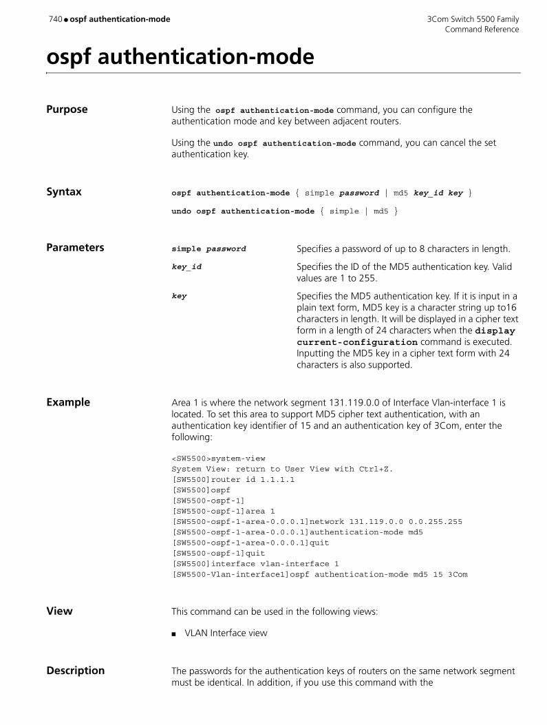
740 ● ospf authentication-mode 3Com Switch 5500 Family Command Reference
ospf authentication-mode
Purpose Using the ospf authentication-mode command, you can configure the authentication mode and key between adjacent routers.
Using the undo ospf authentication-mode command, you can cancel the set authentication key.
Syntax ospf authentication-mode { simple password | md5 key_id key }
undo ospf authentication-mode { simple | md5 }
Parameters simple password Specifies a password of up to 8 characters in length.
key_id Specifies the ID of the MD5 authentication key. Valid values are 1 to 255.
key Specifies the MD5 authentication key. If it is input in a plain text form, MD5 key is a character string up to16 characters in length. It will be displayed in a cipher text form in a length of 24 characters when the display current-configuration command is executed. Inputting the MD5 key in a cipher text form with 24 characters is also supported.
Example Area 1 is where the network segment 131.119.0.0 of Interface Vlan-interface 1 is located. To set this area to support MD5 cipher text authentication, with an authentication key identifier of 15 and an authentication key of 3Com, enter the following:
<SW5500>system-viewSystem View: return to User View with Ctrl+Z.[SW5500]router id 1.1.1.1[SW5500]ospf[SW5500-ospf-1] [SW5500-ospf-1]area 1[SW5500-ospf-1-area-0.0.0.1]network 131.119.0.0 0.0.255.255[SW5500-ospf-1-area-0.0.0.1]authentication-mode md5[SW5500-ospf-1-area-0.0.0.1]quit[SW5500-ospf-1]quit[SW5500]interface vlan-interface 1[SW5500-Vlan-interface1]ospf authentication-mode md5 15 3Com
View This command can be used in the following views:
■ VLAN Interface view
Description The passwords for the authentication keys of routers on the same network segment must be identical. In addition, if you use this command with the

3Com Switch 5500 Family ospf authentication-mode ● 741 Command Reference
authentication-mode command, you can set the authentication type of an area (see Example). By default, the interface does not authenticate the OSPF packets.
Related Command authentication-mode
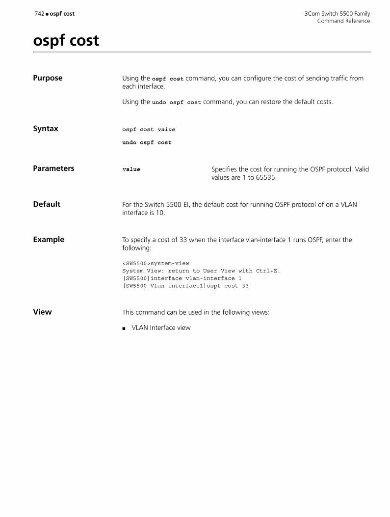
742 ● ospf cost 3Com Switch 5500 Family Command Reference
ospf cost
Purpose Using the ospf cost command, you can configure the cost of sending traffic from each interface.
Using the undo ospf cost command, you can restore the default costs.
Syntax ospf cost value
undo ospf cost
Parameters value Specifies the cost for running the OSPF protocol. Valid values are 1 to 65535.
Default For the Switch 5500-EI, the default cost for running OSPF protocol of on a VLAN interface is 10.
Example To specify a cost of 33 when the interface vlan-interface 1 runs OSPF, enter the following:
<SW5500>system-viewSystem View: return to User View with Ctrl+Z.[SW5500]interface vlan-interface 1[SW5500-Vlan-interface1]ospf cost 33
View This command can be used in the following views:
■ VLAN Interface view

3Com Switch 5500 Family ospf dr-priority ● 743 Command Reference
ospf dr-priority
Purpose Using the ospf dr-priority command, you can configure the priority for electing the "designated router" on an interface.
Using the undo ospf dr-priority command, you can restore the default value.
Syntax ospf dr-priority value
undo ospf dr-priority
Parameters value Specifies the interface priority for electing the "designated router". Valid values are 0 to 255. If not specified, the default value is 1.
Example To set a priority of 8 for Vlan-interface 1, when electing the DR, enter the following:
<SW5500>system-viewSystem View: return to User View with Ctrl+Z.[SW5500]interface vlan-interface 1[SW5500-Vlan-interface1]ospf dr-priority 8
View This command can be used in the following views:
■ VLAN Interface view
Description The priority of the interface determines the qualification of the interface when the "designated router" (DR) is elected. The interface with the higher priority will be always be elected the DR. A priority of 0 will disallow the interface from participating in a DR election.
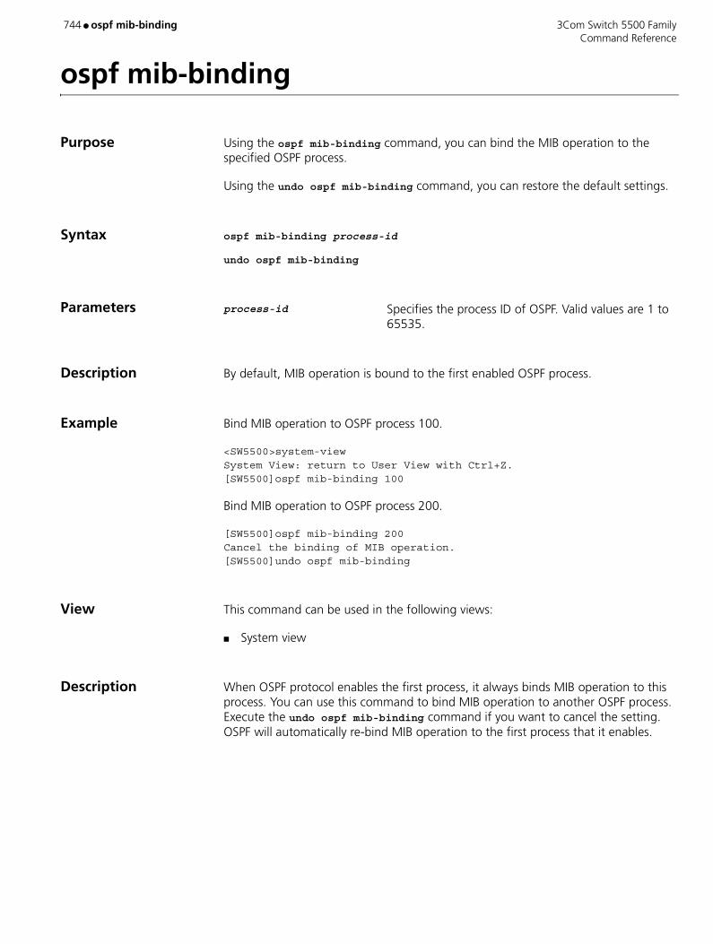
744 ● ospf mib-binding 3Com Switch 5500 Family Command Reference
ospf mib-binding
Purpose Using the ospf mib-binding command, you can bind the MIB operation to the specified OSPF process.
Using the undo ospf mib-binding command, you can restore the default settings.
Syntax ospf mib-binding process-id
undo ospf mib-binding
Parameters process-id Specifies the process ID of OSPF. Valid values are 1 to 65535.
Description By default, MIB operation is bound to the first enabled OSPF process.
Example Bind MIB operation to OSPF process 100.
<SW5500>system-viewSystem View: return to User View with Ctrl+Z.[SW5500]ospf mib-binding 100
Bind MIB operation to OSPF process 200.
[SW5500]ospf mib-binding 200Cancel the binding of MIB operation.[SW5500]undo ospf mib-binding
View This command can be used in the following views:
■ System view
Description When OSPF protocol enables the first process, it always binds MIB operation to this process. You can use this command to bind MIB operation to another OSPF process. Execute the undo ospf mib-binding command if you want to cancel the setting. OSPF will automatically re-bind MIB operation to the first process that it enables.

3Com Switch 5500 Family ospf mtu-enable ● 745 Command Reference
ospf mtu-enable
Purpose Using the ospf mtu-enable command, you can enable the interface to write the MTU value when sending DD packets.
Using the undo ospf mtu-enable command, you can restore the default.
Syntax ospf mtu-enable
undo ospf mtu-enable
Parameters None
Default By default, the MTU value is 0 when sending DD packets, that is the MTU value of the interface is not written.
Example To set interface Vlan-interface 3 to write the MTU value when sending DD packets, enter the following:
<SW5500>system-viewSystem View: return to User View with Ctrl+Z.[SW5500]interface Vlan-interface 3[SW5500-Vlan-interface 3]ospf mtu-enable
View This command can be used in the following views:
■ VLAN Interface view
Description DD packets (Database Description Packet) are sent by the router to describe its own LSDB when the router running OSPF protocol is synchronizing the database.
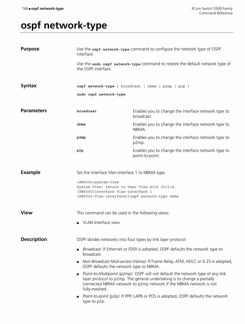
746 ● ospf network-type 3Com Switch 5500 Family Command Reference
ospf network-type
Purpose Use the ospf network-type command to configure the network type of OSPF interface.
Use the undo ospf network-type command to restore the default network type of the OSPF interface.
Syntax ospf network-type { broadcast | nbma | p2mp | p2p }
undo ospf network-type
Parameters broadcast Enables you to change the interface network type to broadcast.
nbma Enables you to change the interface network type to NBMA.
p2mp Enables you to change the interface network type to p2mp.
p2p Enables you to change the interface network type to point-to-point.
Example Set the interface Vlan-interface 1 to NBMA type.
<SW5500>system-viewSystem View: return to User View with Ctrl+Z.[SW5500]interface Vlan-interface 1[SW5500-Vlan-interface1]ospf network-type nbma
View This command can be used in the following views:
■ VLAN Interface view
Description OSPF divides networks into four types by link layer protocol:
■ Broadcast: If Ethernet or FDDI is adopted, OSPF defaults the network type to broadcast.
■ Non-Broadcast Muli-access (nbma): If Frame Relay, ATM, HDLC or X.25 is adopted, OSPF defaults the network type to NBMA.
■ Point-to-Multipoint (p2mp): OSPF will not default the network type of any link layer protocol to p2mp. The general undertaking is to change a partially connected NBMA network to p2mp network if the NBMA network is not fully-meshed.
■ Point-to-point (p2p): If PPP, LAPB or POS is adopted, OSPF defaults the network type to p2p.

3Com Switch 5500 Family ospf network-type ● 747 Command Reference
NBMA means that a network is non-broadcast and multi-accessible. ATM is a typical example. A user can configure the polling interval to specify the interval of sending polling hello packets before the adjacency of the neighboring routers is formed.
Configure the interface type to nonbroadcast on a broadcast network without multi-access capability.
Configure the interface type to p2mp if not all the routers are directly accessible on an NBMA network.
Change the interface type to p2p if the router has only one peer on the NBMA network.
When the network type of an interface is NBMA or it is changed to NBMA manually, the peer command must be used to configure the neighboring point.
Related Command ospf dr-priority

748 ● ospf timer dead 3Com Switch 5500 Family Command Reference
ospf timer dead
Purpose Using the ospf timer dead command, you can configure the amount of dead time allowed to OSPF neighbors, in seconds.
Using the undo ospf timer dead command, you can restore the default value.
Syntax ospf timer dead seconds
undo ospf timer dead
Parameters seconds Specifies the amount of dead time allowed (in seconds). Valid values are 1 to 65535. If not specified, the default dead time allowed to OSPF neighbors is 40 seconds
Example To set the dead time to 80 seconds on interface Vlan-interface 1, enter the following:
<SW5500>system-viewSystem View: return to User View with Ctrl+Z.[SW5500]interface Vlan-interface 1[SW5500-Vlan-interface1]ospf timer dead 80
View This command can be used in the following views:
■ VLAN Interface view
Description If no Hello message is received from a neighbor in the specified time, the neighbor is considered unresponsive or down. The timer dead value should be at least four times that of the timer hello value. The timer dead value for routers on the same network segment must be identical.
Related Command ospf timer hello

3Com Switch 5500 Family ospf timer hello ● 749 Command Reference
ospf timer hello
Purpose Using the ospf timer hello command, you can configure the Hello interval time allowed for an interface.
Using the undo ospf timer hello command, you can restore the interval to the default value.
Syntax ospf timer hello seconds
undo ospf timer hello
Parameters seconds Enables you to enter the Hello interval time allowed (in seconds). Valid values are 1 to 255. If not specified, the default time allowed is 10 seconds for an interface of p2p or broadcast type, and 30 seconds for an interface of nbma or p2mp type.
Example To set a time interval of 20 seconds for transmitting Hello messages on the interface Vlan-interface 1, enter the following:
<SW5500>system-viewSystem View: return to User View with Ctrl+Z.[SW5500]interface Vlan-interface 1[SW5500-Vlan-interface1]ospf timer hello 20
View This command can be used in the following views:
■ VLAN Interface view
Related Command ospf timer dead
750 ● ospf timer poll 3Com Switch 5500 Family Command Reference
ospf timer poll
Purpose Using the ospf timer poll command, you can configure the Hello packet poll interval.
Using the undo ospf timer poll command, you can restore the default poll interval.
Syntax ospf timer poll seconds
undo ospf timer poll
Parameters seconds Specifies the the poll Hello interval (in seconds). Valid values are 1 to 65535. If not specified, the default value is 120 seconds.
Example To set the transmit poll Hello packet interval to 130 seconds for interface Vlan-interface 2, enter the following:
<SW5500>system-viewSystem View: return to User View with Ctrl+Z.[SW5500]interface Vlan-interface 2[SW5500-Vlan-interface2]ospf timer poll 130
View This command can be used in the following views:
■ VLAN Interface view
Description The Poll interval should be at least three times the Hello interval.
3Com Switch 5500 Family ospf timer retransmit ● 751 Command Reference
ospf timer retransmit
Purpose Using the ospf timer retransmit command, you can configure the interval before LSA re-transmission on an interface.
Using the undo ospf timer retransmit command, you can restore the default interval value for LSA re-transmission on an interface.
Syntax ospf timer retransmit interval
undo ospf timer retransmit
Parameters interval Specifies the interval allowed before LSA re-transmission (in seconds). Valid values are 1 to 65535. If not specified, the default value is 5 seconds.
Example To set the retransmit interval between the interface Vlan-interface 1 and the adjacent routers to 12 seconds, enter the following:
<SW5500>system-viewSystem View: return to User View with Ctrl+Z.[SW5500]interface Vlan-interface 1[SW5500-Vlan-interface1]ospf timer retransmit 12
View This command can be used in the following views:
■ VLAN Interface view
Description When a router transmits a Link State Advertisement (LSA) to the peer, it waits for the acknowledgement packet. If no acknowledgement is received from the neighbor within the time you set using this command, the LSA is re-transmitted.
According to RFC2328, the LSA retransmit between adjacent routers should not be set too short to avoid unexpected re-transmission.
752 ● ospf trans-delay 3Com Switch 5500 Family Command Reference
ospf trans-delay
Purpose Using the ospf trans-delay command, you can configure the LSA transmission delay on an interface.
Using the undo ospf trans-delay command, you can restore the default value of the LSA transmission delay.
Syntax ospf trans-delay value
undo ospf trans-delay
Parameters value Specifies the LSA transmission delay (in seconds). Valid values are 1 to 3600. If not specified, the default is 1 second.
Example To set the LSA transmission delay to three seconds on interface Vlan-interface 1, enter the following:
<SW5500>system-viewSystem View: return to User View with Ctrl+Z.
[SW5500]interface Vlan-interface 1[SW5500-Vlan-interface1]ospf trans-delay 3
View This command can be used in the following views:
■ VLAN Interface view
Description LSA will age in the "link state database" (LSDB) of the router as time goes by (add 1 for every second), but it will not age during network transmission. Therefore, it is necessary to add a period of time set by this command to the aging time of LSA before transmitting it.
3Com Switch 5500 Family packet-filter ● 753 Command Reference
packet-filter
Purpose Use the packet-filter command to add packet filtering action to the QoS profile.
Use the undo packet-filter command, you can remove packet filtering action from the QoS profile.
Syntax packet-filter { inbound | outbound } { user-group acl-number [ rule rule] | ip-group acl-number [ rule rule [ link-group acl-number rule rule ] ] | link-group acl-number [ rule rule ] }
undo packet-filter { inbound | outbound } { user-group acl-number [ rule rule ] | ip-group acl-number [ rule rule [ link-group acl-number rule rule ] ] | link-group acl-number [ rule rule ] }
Parameters inbound Filters the inbound packets on the port.
outbound Filters the outbound packets on the port.
user-group acl-number Custom ACL, acl-number. Valid values are 5000 to 5999.
ip-group acl-number Basic or advanced ACL, acl-number. Valid values are 2000 to 3999
link-group acl-number Layer 2 ACL, acl-number. Valid values are 4000 to 4999
rule rule Specifies a match statement in the ACL. Valid values are 0 to 65534. All match statements are selected if you skip this keyword.
Example To add the qos-profile student to this packet filtering action: Filters the inbound packets matching the ACL 4000, enter the following:
<SW5500>system-viewSystem View: return to User View with Ctrl+Z[SW5500]qos-profilestudent[SW5500-qos-profilestudent]packet-filter inbound link-group 4000[SW5500-qos-profilestudent]
View This command can be used in the following views:
■ QoS Profile view

754 ● packet-filter 3Com Switch 5500 Family Command Reference
packet-filter
Purpose Use the packet-filter command to activate the ACL on a specific interface.
Use the undo packet-filter command to disable the ACL on a specific interface.
Syntax packet-filter { inbound | outbound } { user-group acl-number [ rule rule ] | ip-group acl-number [ rule rule [ link-group acl-number rule rule ] ] | link-group acl-number [ rule rule ] }
undo packet-filter { inbound | outbound } { user-group acl-number [ rule rule ] | ip-group acl-number [ rule rule [ link-group acl-number rule rule ] ] | link-group acl-number [ rule rule ] }
Parameters inbound Filters the traffic received by the Ethernet port.
outbound Performs filtering to the packets sent by the interface.
user-group acl-number Activates user-defined ACLs. acl-number: Sequence number of the ACL. Valid values are 5000 to 5999.
ip-group acl-number Activates the IP ACLs, including basic and advanced ACLs. acl-number specifies the sequence number of the ACL. Valid values are 2000 to 3999.
link-group acl-number Activates the Layer 2 ACLs. acl-number specifies the ACL number. Valid values are 4000 to 4999.
rule rule Specifies the rule of an ACL. Valid values are 0 to 65534. if not specified, all sub-items of the ACL will be activated. An ACL can have many rules. They start at 0.
Example Activate ACL 2000 for inbound traffic on interface Ethernet 1/0/1.
<SW5500>system-viewSystem View: return to User View with Ctrl+Z[SW5500]interface Ethernet 1/0/1[SW5500-Ethernet1/0/1]packet-filter inbound ip-group 2000[SW5500-Ethernet1/0/1]
View This command can be used in the following views:
■ Ethernet Port view
3Com Switch 5500 Family parity ● 755 Command Reference
parity
Purpose Use the parity command to configure the parity mode on the AUX (Console) port.
Use the undo parity command to restore the default parity mode (no parity checking).
Syntax parity { even | mark | none | odd | space }
undo parity
Parameters even Sets the Switch to even parity.
mark Sets the Switch to mark parity (1).
none Sets the Switch to perform no parity checking.
odd Sets the Switch to odd parity.
space Sets the Switch to zero parity (0).
Example To set mark parity on the AUX (Console) port, enter the following:
<SW5500>system-viewSystem View: return to User View with Ctrl+Z.[SW5500]user-interface aux 0[SW5500-ui-aux0]parity mark
View This command can be used in the following views:
■ User Interface view
Description This command can only be performed in the AUX User interface view.
756 ● passive 3Com Switch 5500 Family Command Reference
passive
Purpose Use the passive command to set the data transmission mode to be passive mode.
Use the undo passive command to set the data transmission mode to be active mode.
Syntax passive
undo passive
Parameters None
Default By default, the data transmission mode is passive mode
Example Set the data transmission to passive mode.
<SW5500>ftp 1.1.1.1Trying ...Press CTRL+K to abortConnected.220 FTP service ready.User(none):hello331 Password required for hello.Password:230 User logged in[ftp]passive% Passive is on[ftp]
View This command can be used in the following views:
■ FTP Client view

3Com Switch 5500 Family password
Command Reference 757
password
Purpose Use the password command to configure a password display mode for local users.
Use the undo password command to cancel the specified password display mode.
Syntax password { simple | cipher } password
undo password
Parameters simple Specifies to display passwords in simple text.
cipher Specifies to display passwords in cipher text.
password Defines a password, which is a character string of up to 16 characters if it is in simple text and of up to 24 characters if it is in cipher text.
Example To set the user 3Com1 to display the password in simple text, given the password is 20030422, enter the following:
<SW5500>system-viewSystem View: return to User View with Ctrl+Z.[SW5500]local-user 3Com1[SW5500-luser-3Com1]password simple 20030422
View This command can be used in the following views:
■ Local User View
Related Command display local-user

758 ● password 3Com Switch 5500 Family Command Reference
password
Purpose Use the password command to configure or change the system login password for a user.
Syntax password
Parameters None
Example Configure the system login password for the user test to 9876543210.
S5500<S5500> system-viewSystem View: return to User View with Ctrl+Z.S5500[S5500] local-user test New local user added.[S5500-luser-test] passwordPassword:**********confirm:**********
Change the system login password for the user test to 0123456789.
[S5500-luser-test]passwordPassword:**********Confirm :**********Updating the password file ,please wait ...
View This command can be used in the following views:
■ Local User view
3Com Switch 5500 Family password-control ● 759 Command Reference
password-control
Purpose Use the password-control command to configure login passwords.
Use the password-control aging aging-time command to configure the aging time for system login passwords.
Use the password-control length length command to configure the minimum password length for the system login passwords.
Use the password-control login-attempt login-times command to configure the number of password attempts allowed for each user.
Use the password-control history max-record-num command to configure the maximum number of history password records allowed for each user.
Use the password-control alert-before-expire alert-time command to configure the alert time before password expiration, that is, specify the number of days before password expiration to start a daily alert.
Use the password-control authentication-timeout authentication-timeout command to configure the timeout time for user password authentication.
Use the password-control exceed command to configure the processing mode used after password attempt fails.
Syntax password-control aging aging-time
password-control length length
password-control login-attempt login-times [ exceed { lock | unlock | locktime time } ]
password-control history max-record-num
password-control alert-before-expire alert-time
password-control authentication-timeout authentication-timeout
undo password-control { aging | length | login-attempt | exceed | history | alert-before-expire | authentication-timeout }
Parameters aging-time Specifies password aging time. Valid values are 1 day to 365 days If not specified, the default is 90 days.
length Specifies minimum password length. Valid values are any character string from 4 to 32 characters in length. If not specified, the default character string length is 10 characters.
login-times Specifies the number of login attempts allowed for each user. Valid values are 2 to 10. If not specified, the default is 3.
760 ● password-control 3Com Switch 5500 Family Command Reference
max-record-num Specifies the maximum number of history records allowed for each user. Valid values are 2 to 10. If not specified, the default is 4.
alert-time Specifies alert-time period. When the remaining usable time of a password is no more than this time, the user is alerted to the forthcoming password expiration. Valid values are 1 to 30 days. If not specified, the default is 7 days.
authentication-timeout Specifies the timeout time for user authentication. Valid values are 30 seconds to 120 seconds. If not specified, the default is 60 seconds.
exceed Configures the processing mode used after login fails.
lock A processing mode. In lock mode, a user with a log-in failure is added to the blacklist and will be able to re-login only after the administrator manually removes this user from the blacklist.
locktime time A processing mode. In locktime mode, a user with a log-in failure is inhibited from logging in a certain time period, which ranges from 3 to 360 (in minutes) and defaults to 120 minutes; the user is allowed to log into the device again only after this time passes.
unlock A processing mode. In this mode, a login-failure user is allowed to log into the switch again and again without any inhibition.
Default By default, the system operates in locktime mode after password authentication fails.
Example Configure the aging time of the system login passwords to 100 days.
S5500<S5500>system-viewSystem View: return to User View with Ctrl+Z.S5500[S5500] password-control aging 100
Configure the minimum password length of the system login passwords to eight characters.
S5500[S5500] password-control length 8
Configure the number of password attempts allowed for each user to five.
S5500[S5500] password-control login-attempt 5
Configure the maximum number of history password records allowed for each user to 10.
S5500[S5500] password-control history 10
Configure the alert time when users are alerted to their forthcoming expiration to seven days ahead of their expiration times.
S5500[S5500] password-control alert-before-expire 7
3Com Switch 5500 Family password-control ● 761 Command Reference
Configure the timeout time of the user password authentication to 100 seconds.
S5500[S5500] password-control authentication-timeout 100
Configure the maximum number of password attempts to five, and configure the system to allow the attempt failure user to re-log into the device 360 minutes after the failure.
S5500[S5500] password-control login-attempt 5 exceed locktime 360
View This command can be used in the following views:
■ System view

762 ● password-control enable 3Com Switch 5500 Family Command Reference
password-control enable
Purpose Use the password-control enable command to enable various password control functions of the system.
■ Use the password-control aging enable command to enable password aging.
■ Use the password-control length enable command to enable the limitation of the minimum password length.
■ Use the password-control history enable command to enable the history password recording.
■ Use the undo password-control { aging | length | history } enable command to disable password control.
Syntax password-control { aging | length | history } enable
undo password-control { aging | length | history } enable
Parameters None
Default By default, password aging, limitation of minimum password length, and history password recording are all enabled.
Example Enable password aging.
[<S5500]>system-viewSystem View: return to User View with Ctrl+Z.S5500[S5500] password-control aging enablePassword aging enabled for all users. Default: 90 days.
Enable the limitation of the minimum password length.
S5500[S5500]password-control length enablePassword minimum length enabled for all users. Default: 10 characters.
Disable password aging.
S5500[S5500] undo password-control agingPassword aging disabled for all users.
Enable history password recording.
S5500[S5500] password-control history enablePassword history enabled for all users.
Disable history password recording.
S5500[S5500]undo password-control historyPassword history disabled for all users.Display the password control information of the specified user. S5500[S5500]display local-user user-name test
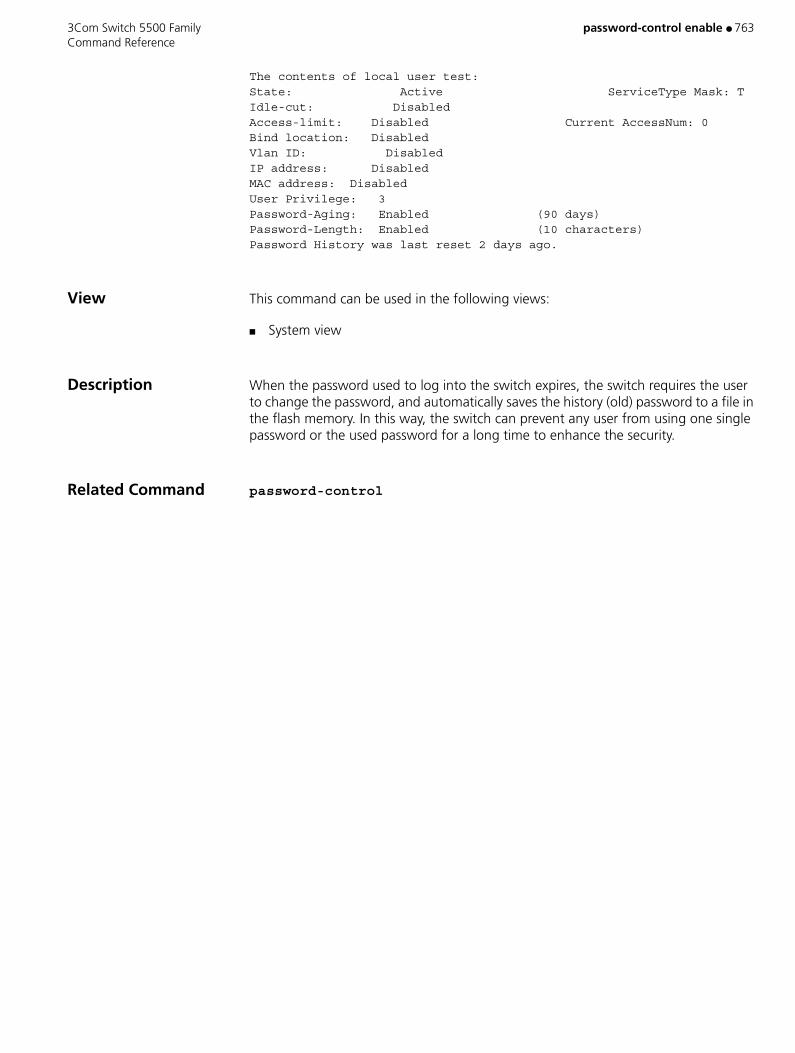
3Com Switch 5500 Family password-control enable ● 763 Command Reference
The contents of local user test:State: Active ServiceType Mask: TIdle-cut: DisabledAccess-limit: Disabled Current AccessNum: 0Bind location: DisabledVlan ID: DisabledIP address: DisabledMAC address: DisabledUser Privilege: 3Password-Aging: Enabled (90 days)Password-Length: Enabled (10 characters)Password History was last reset 2 days ago.
View This command can be used in the following views:
■ System view
Description When the password used to log into the switch expires, the switch requires the user to change the password, and automatically saves the history (old) password to a file in the flash memory. In this way, the switch can prevent any user from using one single password or the used password for a long time to enhance the security.
Related Command password-control
764 ● password-control super 3Com Switch 5500 Family Command Reference
password-control super
Purpose Use the password-control super command to configure the parameters related with the supper passwords, including the password aging time and the minimum password length.
Use the undo password-control super command to restore the default settings for the super passwords.
Syntax password-control super { aging aging-time | length min-length }
undo password-control super { aging | length }
Parameters aging-time Aging time for super passwords. Valid values are 1 to 365 days. If not specified, the default is 90 days.
min-length Minimum length for super passwords. Valid values are 4 to 16 characters. If not specified, the default is 10 characters.
Example Configure the aging time of the super passwords to 10 days.
S5500<S5500> system-viewSystem View: return to User View with Ctrl+Z.S5500[S5500] password-control super aging 10
Description The super passwords are used for the user who has logged into the device and wants to change from a lower privilege level to a higher privilege level.
View This command can be used in the following views:
■ System view

3Com Switch 5500 Family peer ● 765 Command Reference
peer
Purpose Use the peer command to configure the neighboring point if a router is connected to a network of NBMA type.
Use the undo peer command to cancel the configured neighboring point.
Syntax peer ip_address [ dr-priority dr_priority_number ]
undo peer ip_address
Parameters ip_address Specifies the IP address of the neighboring router.
dr_priority_number Specifies the priority value that represents the corresponding priority value of the network neighbor. Valid values are 0 to 255. If not specified, the default value is 1.
Example To configure the IP address of the neighboring router to 10.1.1.1, enter the following:
<SW5500>system-viewSystem View: return to User View with Ctrl+Z.[SW5500]router id 1.1.1.1[SW5500]ospf[SW5500-ospf-1]peer 10.1.1.1
View This command can be used in the following views:
■ OSPF view
766 ● peer 3Com Switch 5500 Family Command Reference
peer
Purpose Use the peer command to configure the destination address of the peer device.
Use the undo peer command to cancel the set destination address. By default, there is no destination address.
Syntax peer ip_address
undo peer ip_address
Parameters ip_address Specifies the interface IP address of the peer router.
Example To specify the sending destination address as 202.38.165.1, enter the following:
<SW5500>system-viewSystem View: return to User View with Ctrl+Z.[SW5500]rip[SW5500-rip]peer 202.38.165.1
View This command can be used in the following views:
■ RIP view
Description 3Com recommends that you do not use this command. RIP can use unicast to exchange information with non-broadcasting networks. If required, you can use this command to specify the destination address of the peer device.

3Com Switch 5500 Family peer connect-interface ● 767 Command Reference
peer connect-interface
Purpose Use the peer connect-interface command to configure MSDP peer.
Use the undo peer connect-interface command to cancel the configured MSDP peer.
Syntax peer peer-address connect-interface interface-type interface-number
undo peer peer-address
Parameters peer-address IP address of the MSDP peer, in dotted decimal notation.
interface-type interface-number Interface type and interface number. The local router
uses the address of this interface as the source IP address to establish TCP connection with its remote MSDP peer.
Example Configure the router whose IP address is 125.10.7.6 as the MSDP peer of the local router.
<S5500> system-view[S5500] msdp[S5500-msdp] peer 125.10.7.6 connect-interface Vlan-interface 100
View This command can be used in the following views:
■ MSDP view
Related Command static-rpf-peer
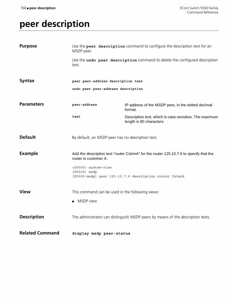
768 ● peer description 3Com Switch 5500 Family Command Reference
peer description
Purpose Use the peer description command to configure the description text for an MSDP peer.
Use the undo peer description command to delete the configured description text.
Syntax peer peer-address description text
undo peer peer-address description
Parameters peer-address IP address of the MSDP peer, in the dotted decimal format.
text Description text, which is case sensitive. The maximum length is 80 characters.
Default By default, an MSDP peer has no description text.
Example Add the description text “router CstmrA” for the router 125.10.7.6 to specify that the router is customer A.
<S5500> system-view[S5500] msdp[S5500-msdp] peer 125.10.7.6 description router CstmrA
View This command can be used in the following views:
■ MSDP view
Description The administrator can distinguish MSDP peers by means of the description texts.
Related Command display msdp peer-status

3Com Switch 5500 Family peer mesh-group ● 769 Command Reference
peer mesh-group
Purpose Use the peer mesh-group command to add an MSDP peer in a mesh group.
Use the undo peer mesh-group command to cancel the configuration.
Syntax peer peer-address mesh-group name
undo peer peer-address mesh-group name
Parameters peer-address IP address of an MSDP peer in a mesh group, in the dotted decimal format.
name Name of a mesh group, case sensitive, containing 1 to 32 characters.
Default By default, an MSDP peer does not belong to any mesh group.
Example Configure the MSDP peer whose address is 125.10.7.6 as a member of the mesh group Grp1.
<S5500> system-view[S5500] msdp[S5500-msdp] peer 125.10.7.6 mesh-group Grp1
View This command can be used in the following views:
■ MSDP view
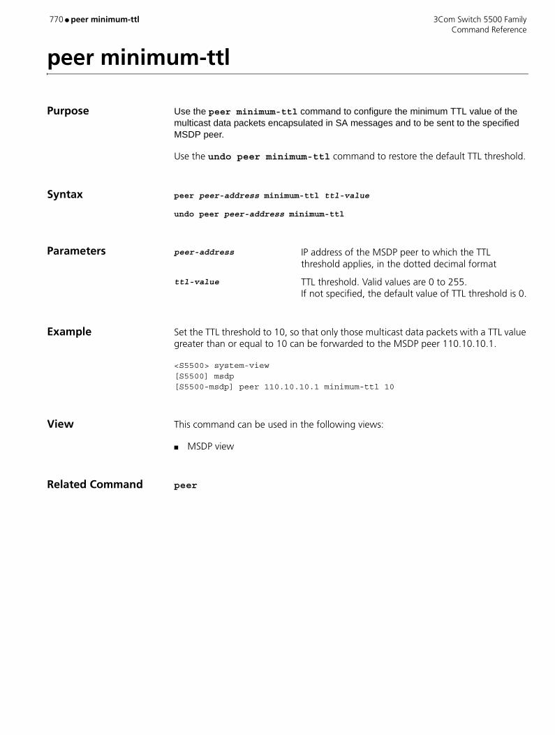
770 ● peer minimum-ttl 3Com Switch 5500 Family Command Reference
peer minimum-ttl
Purpose Use the peer minimum-ttl command to configure the minimum TTL value of the multicast data packets encapsulated in SA messages and to be sent to the specified MSDP peer.
Use the undo peer minimum-ttl command to restore the default TTL threshold.
Syntax peer peer-address minimum-ttl ttl-value
undo peer peer-address minimum-ttl
Parameters peer-address IP address of the MSDP peer to which the TTL threshold applies, in the dotted decimal format
ttl-value TTL threshold. Valid values are 0 to 255. If not specified, the default value of TTL threshold is 0.
Example Set the TTL threshold to 10, so that only those multicast data packets with a TTL value greater than or equal to 10 can be forwarded to the MSDP peer 110.10.10.1.
<S5500> system-view[S5500] msdp[S5500-msdp] peer 110.10.10.1 minimum-ttl 10
View This command can be used in the following views:
■ MSDP view
Related Command peer

3Com Switch 5500 Family peer-public-key end ● 771 Command Reference
peer-public-key end
Purpose Use the peer-public-key end command to return to system view from public key view.
Syntax peer-public-key end
Parameters None
Example Exit from public key view.
<S5500> system-view[S5500] rsa peer-public-key 3Com003[S5500-rsa-public-key] peer-public-key end[S5500]
View This command can be used in the following views:
■ Public Key view
Related Commands ■ public-key-code begin
■ rsa peer-public-key

772 ● peer request-sa-enable 3Com Switch 5500 Family Command Reference
peer request-sa-enable
Purpose Use the peer request-sa-enable command to enable the router to send an SA request message to the specified MSDP peer upon receipt of a Join message.
Use the undo peer request-sa-enable command to remove the configuration.
Syntax peer peer-address request-sa-enable
undo peer peer-address request-sa-enable
Parameters peer-address IP address of the MSDP peer, in dotted decimal format.
Default By default, upon receipt of a Join message, the router sends no SA request message to the MSDP peer but waits for the next SA message.
Example Configure to send an SA request message to the MSDP peer 125.10.7.6.
<S5500> system-view[S5500] msdp[S5500-msdp] peer 125.10.7.6 request-sa-enable
View This command can be used in the following views:
■ MSDP view
Related Command cache-sa-enable
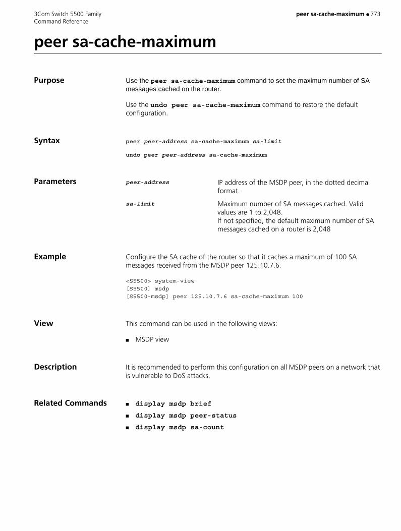
3Com Switch 5500 Family peer sa-cache-maximum ● 773 Command Reference
peer sa-cache-maximum
Purpose Use the peer sa-cache-maximum command to set the maximum number of SA messages cached on the router.
Use the undo peer sa-cache-maximum command to restore the default configuration.
Syntax peer peer-address sa-cache-maximum sa-limit
undo peer peer-address sa-cache-maximum
Parameters peer-address IP address of the MSDP peer, in the dotted decimal format.
sa-limit Maximum number of SA messages cached. Valid values are 1 to 2,048. If not specified, the default maximum number of SA messages cached on a router is 2,048
Example Configure the SA cache of the router so that it caches a maximum of 100 SA messages received from the MSDP peer 125.10.7.6.
<S5500> system-view[S5500] msdp[S5500-msdp] peer 125.10.7.6 sa-cache-maximum 100
View This command can be used in the following views:
■ MSDP view
Description It is recommended to perform this configuration on all MSDP peers on a network that is vulnerable to DoS attacks.
Related Commands ■ display msdp brief
■ display msdp peer-status
■ display msdp sa-count
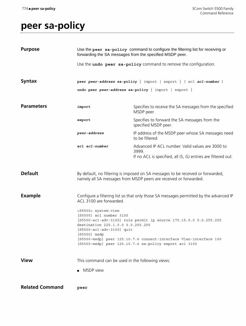
774 ● peer sa-policy 3Com Switch 5500 Family Command Reference
peer sa-policy
Purpose Use the peer sa-policy command to configure the filtering list for receiving or forwarding the SA messages from the specified MSDP peer.
Use the undo peer sa-policy command to remove the configuration.
Syntax peer peer-address sa-policy { import | export } [ acl acl-number ]
undo peer peer-address sa-policy { import | export }
Parameters import Specifies to receive the SA messages from the specified MSDP peer.
export Specifies to forward the SA messages from the specified MSDP peer.
peer-address IP address of the MSDP peer whose SA messages need to be filtered.
acl acl-number Advanced IP ACL number. Valid values are 3000 to 3999. If no ACL is specified, all (S, G) entries are filtered out.
Default By default, no filtering is imposed on SA messages to be received or forwarded, namely all SA messages from MSDP peers are received or forwarded.
Example Configure a filtering list so that only those SA messages permitted by the advanced IP ACL 3100 are forwarded.
<S5500> system-view[S5500] acl number 3100[S5500-acl-adv-3100] rule permit ip source 170.15.0.0 0.0.255.255 destination 225.1.0.0 0.0.255.255[S5500-acl-adv-3100] quit[S5500] msdp[S5500-msdp] peer 125.10.7.6 connect-interface Vlan-interface 100[S5500-msdp] peer 125.10.7.6 sa-policy export acl 3100
View This command can be used in the following views:
■ MSDP view
Related Command peer
3Com Switch 5500 Family peer sa-request-policy ● 775 Command Reference
peer sa-request-policy
Purpose Use the peer sa-request-policy command to limit the SA request messages the router receives from an MSDP peer.
Use the undo peer sa-request-policy command to remove the limitation.
Syntax peer peer-address sa-request-policy [ acl acl-number ]
undo peer peer-address sa-request-policy
Parameters peer-address IP address of an MSDP peer, the SA request messages sent from which will be filtered.
acl-number Basic IP ACL number, describing a multicast group address. Valid values are 2000 to 2999. If no ACL is specified, all SA request messages will be ignored.
Default By default, the router receives all SA request messages from the MSDP peer.
Example Configure an ACL so that SA request messages from the group address range of 225.1.1.0/24 and from the MSDP peer 175.58.6.5 are received while other SA messages are ignored.
<S5500> system-view[S5500] acl number 2001[S5500-acl-basic-2001] rule permit source 225.1.1.0 0.0.0.255[S5500-acl-basic-2001] quit[S5500] msdp[S5500-msdp] peer 175.58.6.5 sa-request-policy acl 2001
View This command can be used in the following views:
■ MSDP view
Description If no ACL is specified, all SA requests will be ignored. If an ACL is specified, only those SA request messages from the groups that match the ACL rule will be processed while others are ignored.
Related Command peer
776 ● pim 3Com Switch 5500 Family Command Reference
pim
Purpose Use the pim to enter the PIM View.
Use the undo pim to clear the configurations in PIM View.
Syntax pim
undo pim
Parameters None
Example Enable multicast and enter the PIM View.
<SW5500>system-viewSystem View: return to User View with Ctrl+Z[SW5500]multicast routing-enable[SW5500]pim[SW5500-pim]
View This command can be used in the following views:
■ System view
Description The global parameters of PIM can only be configured in PIM View.
3Com Switch 5500 Family pim bsr-boundary ● 777 Command Reference
pim bsr-boundary
Purpose Use the pim bsr-boundary to configure an interface to be the PIM domain border.
Use the undo pim bsr-boundary to remove the border.
Syntax pim bsr-boundary
undo pim bsr-boundary
Parameters None
Default By default, no domain border is set.
Example Configure domain border on VLAN-interface10.
<SW5500>system-viewSystem View: return to User View with Ctrl+Z[SW5500]interface Vlan-interface-10[SW5500-vlan-interface10]pim bsr-boundary
View This command can be used in the following views:
■ Interface view
Description You can use this command to set a border for bootstrap messages, that is to say, bootstrap messages cannot pass interfaces that are configured with the pim bsr-boundary command while other PIM messages can. In this way, the network is divided into different BSR domains.
It should be noted that this command cannot set up multicast boundaries. It only sets up a PIM domain bootstrap message border.
Related Command c-bsr
778 ● pim dm 3Com Switch 5500 Family Command Reference
pim dm
Purpose Use the pim dm to enable PIM-DM (Dense Mode).
Use the undo pim dm to disable PIM-DM.
Syntax pim dm
undo pim dm
Parameters None
Default By default, PIM-DM is disabled.
Example Enable PIM DM on VLAN-interface10 of the Ethernet Switch.
<SW5500>system-viewSystem View: return to User View with Ctrl+Z[SW5500]multicast routing-enable[SW5500]interface Vlan-interface-10[SW5500-vlan-interface10]pim dm
View This command can be used in the following views:
■ Interface view
Description Once PIM-DM is enabled on an interface, PIM-SM cannot be enabled on the same interface and vice versa.

3Com Switch 5500 Family pim neighbor-limit ● 779 Command Reference
pim neighbor-limit
Purpose Use the pim neighbor-limit command to limit the PIM neighbors on an interface. No neighbor can be added when the limit is reached.
Use the undo pim neighbor-limit command to restore the default setting.
Syntax pim neighbor-limit limit
undo pim neighbor-limit
Parameters limit Limits of PIM neighbors on the interface. Valid values are 0 to 128.
Default By default, the PIM neighbors on the interface are limited to 128.
Example Limit the PIM neighbors on the Vlan-interface10 to 50.
<SW5500>system-viewSystem View: return to User View with Ctrl+Z[SW5500]multicast routing-enable[SW5500]interface Vlan-interface-10[SW5500-Vlan-interface10]pim neighbor-limit 50
View This command can be used in the following views:
■ VLAN Interface view
Description If the existing PIM neighbors exceed the configured value during configuration, they will not be deleted.

780 ● pim neighbor-policy 3Com Switch 5500 Family Command Reference
pim neighbor-policy
Purpose Use the pim neighbor-policy command to filter the PIM neighbors on the current interface.
Use the undo pim neighbor-policy command to remove the filter.
Syntax pim neighbor-policy acl-number
undo pim neighbor-policy
Parameters acl-number Basic ACL number, in the range of 1to 99.
Example Configure that 10.10.1.2 can serve as a PIM neighbor of the Vlan-interface10, but not 10.10.1.1.
<SW5500>system-viewSystem View: return to User View with Ctrl+Z[SW5500]multicast routing-enable[SW5500]interface Vlan-interface-10[SW5500-Vlan-interface10]pim neighbor-policy 2000[SW5500-Vlan-interface10]quit[SW5500]acl number 2000[SW5500-acl-basic-2000]rule permit source 10.10.1.2 0[SW5500-acl-basic-2000]rule deny source 10.10.1.1 0
View This command can be used in the following views:
■ VLAN Interface view
Description Only the routers that match the filtering rule in the ACL can serve as a PIM neighbor of the current interface.
The new configuration overwrites the old one if you run the command for a second time.
3Com Switch 5500 Family pim sm ● 781 Command Reference
pim sm
Purpose Use the pim sm to enable the PIM-SM protocol on an interface.
Use the undo pim sm to disable the PIM-SM protocol.
Syntax pim sm
undo pim sm
Parameters None
Default By default, PIM-SM is disabled.
Example Enable PIM-SM on VLAN-interface10.
<SW5500>system-viewSystem View: return to User View with Ctrl+Z[SW5500]multicast routing-enable[SW5500]interface Vlan-interface-10[SW5500-vlan-interface10]pim sm
View This command can be used in the following views:
■ Interface view
Description Once PIM-SM is enabled on an interface, PIM-DM cannot be enabled on the same interface and vice versa.
782 ● pim timer hello 3Com Switch 5500 Family Command Reference
pim timer hello
Purpose Use the pim timer hello to configure the interval of sending PIM router Hello messages.
Use the undo pim timer hello to restore the default interval value.
Syntax pim timer hello seconds
undo pim timer hello
Parameters seconds Interval of sending Hello messages in seconds. Valid values are 1 to 18000. If not specified, the default is 30 seconds.
Example Configure to transmit Hello packet via VLAN-interface10 every 40 seconds.
<SW5500>system-viewSystem View: return to User View with Ctrl+Z[SW5500]multicast routing-enable[SW5500]interface Vlan-interface-10[SW5500-vlan-interface10]pim timer hello 40
View This command can be used in the following views:
■ Interface view
3Com Switch 5500 Family ping ● 783 Command Reference
ping
Purpose Use the ping command to check the IP network connection and the reachability of the host.
Syntax ping [ -a ip-address ] [-c count ] [ -d ] [-h tll ][ -i {interface-type interface-num | interface-name } ][ ip ] [ -n ] [ - p pattern ] [ -q ] [ -r ] [ -s packetsize ] [ -t timeout ] [-tos tos ] [ -v ] string
Parameters -a ip-address Specifies the source IP address to transmit ICMP ECHO-REQUEST.
-c count Specifies how many times the ICMP ECHO-REQUEST packet will be transmitted, ranging from 1 to 4294967295.
-d Configures the socket to be in DEBUGGING mode.
-h ttl Configures TTL value for echo requests to be sent, range from 1 to 255.
-i Configures to choose packet sent on the interface.
interface-type Specifies the interface type.
interface-num Specifies the interface number.
interface-name Specifies the interface name.
ip Chooses IP ICMP packet.
-n Configures to take the host parameter as IP address without domain name resolution.
-p pattern is the hexadecimal padding of ICMP ECHO-REQUEST, for example, -p ff pads the packet completely with ff.
-q Configure not to display any other detailed information except statistics.
-r Record route.
-s packetsize Specifies the length of ECHO-REQUEST (excluding IP and ICMP packet header) in bytes.
-t timeout Maximum waiting time after sending the ECHO-REQUEST (measured in ms).
-tos tos Specifies TOS value for echo requests to be sent, range from 0 to 255.
-v Shows other received ICMP packets (non ECHO-RESPONSE).
string Destination host domain name or IP address.

784 ● ping 3Com Switch 5500 Family Command Reference
Default By default, when the parameters are not specified:
■ The ECHO-REQUEST message will be sent for 5 times.
■ The socket is not in DEBUGGING mode.
■ The TTL value for echo requests is 255.
■ The host will be treated as IP address first. If it is not an IP address, perform domain name resolution.
■ The default padding operation starts from 0x01 and ends on 0x09 (progressively), then performs again.
■ All information, including statistics, is shown.
■ Routes are not recorded.
■ The ECHO-REQUEST is sent according to route selection.
■ The default length of ECHO-REQUEST is 56 bytes.
■ The default timeout of ECHO-RESPONSE is 2000 ms.
■ Other ICMP packets (non ECHO-RESPONSE) do not display.
■ The TOS value of echo requests is 0.
Example Check whether the host 202.38.160.244 is reachable.
<SW5500>ping 202.38.160.244ping 202.38.160.244 : 56 data bytesReply from 202.38.160.244 : bytes=56 sequence=1 ttl=255 time = 1msReply from 202.38.160.244 : bytes=56 sequence=2 ttl=255 time = 2msReply from 202.38.160.244 : bytes=56 sequence=3 ttl=255 time = 1msReply from 202.38.160.244 : bytes=56 sequence=4 ttl=255 time = 3msReply from 202.38.160.244 : bytes=56 sequence=5 ttl=255 time = 2ms--202.38.160.244 ping statistics--5 packets transmitted5 packets received0% packet lossround-trip min/avg/max = 1/2/3 ms
View This command can be used in the following views:
■ User view
Description The ping command sends ICMP ECHO-REQUEST message to the destination. If the network to the destination works well, then the destination host will send ICMP ECHO-REPLY to the source host after receiving ICMP ECHO-REQUEST.
Perform the ping command to troubleshoot the network connection and line quality. The output information includes:
■ Responses to each of the ECHO-REQUEST messages. If the response message is not received until timeout, output "Request time out". Or display response message bytes, packet sequence number, TTL and response time.
■ The final statistics, including number of sent packets, number of response packets received, percentage of non-response packets and minimal/maximum/average value of response time.

3Com Switch 5500 Family ping ● 785 Command Reference
If the network transmission rate is too low to increase the response message timeout.
Related Command remote-ping
tracert
786 ● pki 3Com Switch 5500 Family Command Reference
pki
Purpose Use the pki command to specify PKI module configuration information.
Syntax pki [ certificate | delete-certificate | domain | entity | import-certificate | request-certificate | retrieval-crl | validate-certificate ]
Parameters certificate Specifies certificate.
delete-certificate Specifies delete PKI certificates.
domain Specifies PKI domain configuration information.
entity Specifies the PKI entity configuration.
import-certificate Specifies import certificate.
request-certificate Specifies request certificate.
retrieval-crl Specifies retrieval CRL operations.
validate-certificate Validates certificate operations.
View This command can be used in the following views:
■ System view

3Com Switch 5500 Family poe enable ● 787 Command Reference
poe enable
Purpose Use the poe enable command to enable the PoE feature on a port.
Use the undo poe enable command to disable the PoE feature on a port.
Syntax poe enable
undo poe enable
Parameters None
Default By default, the PoE feature on each port is enabled.
Example Enable the PoE feature on the current port.
[SW5500-Ethernet1/0/3]poe enable Port power supply is enabled
Disable the PoE feature on the current port.
[SW5500-Ethernet1/0/3]undo poe enable Port power supply is disabled
View This command can be used in the following views:
■ Ethernet Port view

788 ● poe legacy enable 3Com Switch 5500 Family Command Reference
poe legacy enable
Purpose Use the poe legacy enable command to enable the nonstandard-PD detect function.
Use the undo poe legacy enable command to disable the nonstandard-PD detect function.
Syntax poe legacy enable
undo poe legacy enable
Parameters None
Default By default, the nonstandard-PD detect function is disabled.
Example Enable the nonstandard-PD detect function.
[SW5500]poe legacy enable Legacy detection is enabled
Disable the nonstandard-PD detect function.
[SW5500]undo poe legacy enable Legacy detection is disabled
View This command can be used in the following views:
■ System view
Description PDs compliant with 802.3af standards are called standard PDs.

3Com Switch 5500 Family poe max power ● 789 Command Reference
poe max power
Purpose Use the poe max-power command to configure the maximum power that can be supplied by current port.
Use the undo poe max-power command to restore the maximum power supplied by current port to the default value.
Syntax poe max-power max-power
undo poe max-power
Parameters max-power Maximum power distributed to the port. Valid values are 1000 to 15400 mW.
Default By default, the maximum power that a port can supply is 15400 mW.
Example Set the maximum power supplied by current port.
[SW5500-Ethernet1/0/3]poe max-power 15000 Set Port max power successfully
Restore the default maximum power on the current port.
[SW5500-Ethernet1/0/3]undo poe max-power Set Port max power successfully
View This command can be used in the following views:
■ Ethernet Port view
Description The unit of power is mW. You can set the power in the granularity of 100 mW. The actual maximum power will be 5% larger than what you have set allowing for the effect of transient peak power.
790 ● poe mode 3Com Switch 5500 Family Command Reference
poe mode
Purpose Use the poe mode command to configure the PoE mode on the current port.
Use the undo poe mode command to restore the PoE mode on the current port to the default mode.
Syntax poe mode { signal | spare }
undo poe mode
Parameters signal Supply power through the signal line.
spare Supply power through the spare line. Currently, the Switch 5500 Family does not support spare mode. If the subordinate PD only supports the spare mode, a conversion is needed.
Default By default, the port is powered through the signal cable.
Example Set the PoE mode on current port to signal.
[SW5500-Ethernet1/0/3]poe mode signal Set PoE mode successfully
View This command can be used in the following views:
■ Ethernet Port view
3Com Switch 5500 Family poe power-management ● 791 Command Reference
poe power-management
Purpose Use the poe power-management command to configure the PoE management mode of port used in the case of power overloading.
Use the undo poe power-management command to restore the default mode.
Syntax poe power-management { auto | manual }
undo poe power-management
Parameters auto Adopt the auto mode, a PoE management mode based on port priority.
manual Adopt the manual mode.
Default By default, the PoE management mode on port is auto.
Example Configure the PoE management mode on port to auto.
[SW5500]poe power-management auto Auto Power Management is enabled
Restore the default management mode.
[SW5500]undo poe power-management Auto Power Management is enabled
View This command can be used in the following views:
■ System view

792 ● poe priority 3Com Switch 5500 Family Command Reference
poe priority
Purpose Use the poe priority command to configure the power supply priority on a port.
Use the undo poe priority command to restore the default priority.
Syntax poe priority { critical | high | low }
undo poe priority
Parameters critical Sets the port priority to critical.
high Sets the port priority to high.
low Sets the port priority to low.
Default By default, the port priority is low.
Example Set the port priority to critical.
[SW5500-Ethernet1/0/3]poe priority criticalSet Port PSE priority successfully
Restore the default priority.
[SW5500-Ethernet1/0/3]undo poe priority Set Port PSE priority successfully
View This command can be used in the following views:
■ Ethernet Port view
Description If there are too many ports with critical priority, the total power these ports need might exceed the maximum power supplied by the equipment, that is, 300W. In this case, no new PD can be added to the switch.
When the remaining power of the whole equipment is below 18.8 W, no new PD can be added to the Switch.
3Com Switch 5500 Family poe-profile ● 793 Command Reference
poe-profile
Purpose Use the poe-profile command to create a PoE Profile.
Use the undo poe-profile command to delete an existing PoE Profile.
Syntax poe-profile profilename
undo poe-profile profilename
Parameters profilename Name of PoE Profile, consisting of a string from 1 to 15 characters long, beginning with English letters (in upper- or lowercase letters), and cannot be reserved keywords like all, interface, user, undo, and mode.
Example Create a PoE Profile by the name of profile-test.
<S5500> system-viewSystem View: return to User View with Ctrl+Z.[S5500] poe-profile profile-test
View This command can be used in the following views:
■ System view
Description The maximum number of PoE Profiles that can be configured for an SWITCH 5500 switch is 256.
794 ● poe update 3Com Switch 5500 Family Command Reference
poe update
Purpose Use the poe update command to update the PSE processing software online
Syntax poe update { refresh | full } filename
Parameters refresh The refresh update mode is used when the PSE processing software is valid.
full The full update mode is used when the PSE has no valid processing software.
filename Update file name, with a length of 1 to 64 characters.
Example Update the PSE processing software online.
[SW5500]poe update refresh 0290_021.s19 ................................................................... ........................................................................................................................................................................................................................................................................................................................................................................................................................................................................................................................................................................... Update PoE board successfully
View This command can be used in the following views:
■ System view
Description Note:
� The full mode is used only when you cannot use the refresh mode.
� When the update procedure in refresh mode is interrupted for some unexpected reason (for example, power-off) or some errors occur, you can use the full mode to re-update.
� When the PSE processing software is damaged (that is, all the PoE commands cannot be successfully executed), you can use the full mode to update and restore the software.
3Com Switch 5500 Family port ● 795 Command Reference
port
Purpose Using the port command, you can add one port or one group of ports to a VLAN.
Using the undo port command, you can cancel one port or one group of ports from a VLAN.
Syntax port interface_list
undo port interface_list
Parameters interface_list List of Ethernet ports to be added to or deleted from a certain VLAN, expressed as interface_list= {{ interface_type interface_num | interface_name } [ to { interface_type interface_num | interface_name } ] }&<1-10>.�
interface_type is the interface type, interface_num is the interface number and interface_name is the interface name. For their meanings and value range, see the parameter of Port in this document. The interface number after keyword to must be larger than or equal to the port number before to.
&<1-10> Represents the repeatable times of parameters. A value of 1 is the minimum and 10 is the maximum.
Example Add Ethernet1/0/2 through Ethernet1/0/4 to VLAN 2.
<SW5500>system-viewSystem View: return to User View with Ctrl+Z.[SW5500]vlan 2[SW5500-vlan2]port ethernet1/0/2 to ethernet1/0/4
View This command can be used in the following views:
■ VLAN view
Description You can add/delete trunk port and hybrid ports to/from a VLAN by port and undo port commands in Ethernet Port View, but not in VLAN View.
Related Command display vlan

796 ● port access vlan 3Com Switch 5500 Family Command Reference
port access vlan
Purpose Use the port access vlan command to assign the access port to a specified VLAN.
Use the undo port access vlan command to remove the access port from the VLAN.
Syntax port access vlan vlan_id
undo port access vlan
Parameters vlan_id Specifies a VLAN ID. Valid values are 2 to 4094, as defined in IEEE 802.1Q.
Example To assign Ethernet port 1/0/1 to VLAN3, enter the following.
<SW5500>system-viewSystem View: return to User View with Ctrl+Z.[SW5500]vlan 3[SW5500-vlan3]quit[SW5500]interface ethernet 1/0/1[SW5500-Ethernet1/0/1]port access vlan 3[SW5500-Ethernet1/0/1]
View This command can be used in the following views:
■ Ethernet Port view

3Com Switch 5500 Family port hybrid protocol-vlan vlan ● 797 Command Reference
port hybrid protocol-vlan vlan
Purpose Use the port hybrid protocol-vlan vlan command to deliver specified protocol VLANs to a port.
Use the undo port hybrid protocol-vlan vlan command to remove the associations between specified protocol-based VLANs and a port.
Syntax port hybrid protocol-vlan vlan vlan-id { protocol-index [ to protocol-end ] | all }
undo port hybrid protocol-vlan vlan vlan-id { protocol-index [ to protocol-end ] | all }
Parameters vlan-id Specifies a VLAN ID. Valid values are 1 to 4,094.
protocol-index Beginning protocol index. Valid values are 0 to 4 and must not be bigger than the end value of the protocol index.
protocol-end End protocol index. Valid values are 0 to 4 and must not be smaller than the start value of the protocol index.
all Specifies all protocols.
Example Associate Ethernet1/0/1 port with protocols 0 through 4 of VLAN 3 (assuming that VLAN 3 is a protocol-based VLAN).
<S5500> system-viewSystem View: return to User View with Ctrl+Z.[S5500] interface ethernet1/0/1[S5500-Ethernet1/0/1] port hybrid protocol-vlan vlan 3 0 t
View This command can be used in the following views:
■ Ethernet Port view
Description You can only associate Hybrid ports with protocol-based VLANs at present. Before associate a port with a protocol-based VLAN, make sure the port belongs to the VLAN.
Related Command display protocol-vlan interface

798 ● port hybrid pvid vlan 3Com Switch 5500 Family Command Reference
port hybrid pvid vlan
Purpose Use the port hybrid pvid vlan command to configure the default VLAN ID of the hybrid port.
Use the undo port hybrid pvid command to restore the default VLAN ID of the hybrid port.
Syntax port hybrid pvid vlan vlan_id
undo port hybrid pvid
Parameters vlan_id Specifies a VLAN ID. Valid values are 2 to 4094, as defined in IEEE 802.1Q. If not specified, the default is 1.
Example To configure the default VLAN of the hybrid port Ethernet1/0/1 to VLAN100, enter the following.
<SW5500>system-viewSystem View: return to User View with Ctrl+Z.[SW5500]interface ethernet 1/0/1[SW5500-Ethernet1/0/1]port link-type hybrid[SW5500-Ethernet1/0/1]port hybrid pvid vlan 100[SW5500-Ethernet1/0/1]
View This command can be used in the following views:
■ Ethernet Port view
Description Hybrid port can be configured together with the isolate-user-vlan. But if the default VLAN has set mapping in the isolate-user-vlan, the default VLAN ID cannot be modified. If you want to modify it, cancel the mapping first.
The default VLAN ID of local hybrid port must be consistent with that of the peer one, otherwise, the packets cannot be properly transmitted.
Related Command port link-type
3Com Switch 5500 Family port hybrid vlan ● 799 Command Reference
port hybrid vlan
Purpose Use the port hybrid vlan command to add the port to the specified VLAN(s). The port needs to have been made a hybrid port before you can do this. See the related command below.
Use the undo port hybrid vlan command to remove the port from the specified VLAN(s).
Syntax port hybrid vlan vlan_id_list { tagged | untagged }
undo port hybrid vlan vlan_id_list
Parameters vlan_id_list Specifies a VLAN ID, or more than one VLAN ID, in the range 2 to 4094. The hybrid port will be added to the specified VLANs. This can be a single VLAN, a series of individual VLANs separated by a space, or the the first VLAN in a range of VLANs (vlan_id to last_vlan_id).
You can enter up to ten vlan_id parameters in one port hybrid vlan command.
tagged Specifies to tag the port for the specified VLAN.
untagged Specifies to leave the port untagged for the specified VLAN.
Example To add the port Ethernet1/0/1 to VLAN 2, VLAN 4 and all VLANs in the range 50 to 100 as a tagged port, enter the following:
<SW5500>system-viewSystem View: return to User View with Ctrl+Z.[SW5500]interface ethernet 1/0/1[SW5500-Ethernet1/0/1]port link-type hybrid[SW5500-Ethernet1/0/1]quit[SW5500]vlan 2[SW5500-vlan2]quit[SW5500]interface e1/0/1[SW5500-Ethernet1/0/1]port hybrid vlan 2 4 50 to 100 tagged[SW5500-Ethernet1/0/1]
View This command can be used in the following views:
■ Ethernet Port view
Description A hybrid port can belong to multiple VLANs. A port can only be added to a VLAN if the VLAN has already been created. See the vlan vlan-vid command.
Related Command port link-type

800 ● port isolate 3Com Switch 5500 Family Command Reference
port isolate
Purpose Use the port isolate command to add a port to an isolation group using the following commands, and achieves port-to-port isolation between this port and other ports of this group, that is, Layer 2 forwarding between the isolated ports is not available.
Use the undo port isolate command to remove a port from an isolation group.
Syntax port isolate
undo port isolate
Parameters None
Default By default, a port is not in an isolation group, namely Layer 2 forwarding is achievable between this port and other ports.
Example To add Ethernet1/0/1 and Ethernet1/0/2 to isolation group, enter the following:
<SW5500>system-viewSystem View: return to User View with Ctrl+Z.[SW5500]interface ethernet 1/0/1[SW5500-Ethernet1/0/1]port isolate[SW5500-Ethernet1/0/1]quit[SW5500]interface ethernet 1/0/2[SW5500-Ethernet1/0/2]port isolate
View This command can be used in the following views:
■ Ethernet Port view
3Com Switch 5500 Family port link-aggregation group ● 801 Command Reference
port link-aggregation group
Purpose Use the port link-aggregation group agg_id command to add an Ethernet port into a manual or static aggregation group.
Use the undo port link-aggregation group command to delete an Ethernet port from a manual or static aggregation group
Syntax port link-aggregation group agg_id
undo port link-aggregation group
Parameters agg_id Aggregation group ID. Valid values are 1 to 416.
Example To add Ethernet1/0/1 into aggregation group 22, enter the following:
<SW5500>system-viewSystem View: return to User View with Ctrl+Z.[SW5500]link-aggregation group 22 mode manual[SW5500]interface ethernet 1/0/1[SW5500-Ethernet1/0/1]port link-aggregation group 22#Apr 2 03:29:48:954 2000 SW5500 LAGG/2/AggPortInactive:- 1 -Trap 1.3.6.1.4.1.2011.5.25.25.2.2: TrapIndex 31465473 Aggregation Group 22: port member Ethernet1/0/1 becomes INACTIVE![SW5500-Ethernet1/0/1]
View This command can be used in the following views:
■ Ethernet Port view
Related Command display link-aggregation verbose

802 ● port link-type 3Com Switch 5500 Family Command Reference
port link-type
Purpose Use the port link-type command to configure the link type of the Ethernet port.
Use the undo port link-type command to restore the port as default status.
Syntax port link-type { access | hybrid | trunk | xrn-fabric }
undo port link-type
Parameters access Specifies to configure the port as an access port.
hybrid Specifies to configure the port as a hybrid port
trunk Specifies to configure the port as a trunk port.
xrn-fabric Specifies to configure the port as a Fabric port.
Default By default, a port is an access port.
Example To configure the Ethernet port Ethernet1/0/1 as a trunk port, enter the following:
<SW5500>system-viewSystem View: return to User View with Ctrl+Z.[SW5500]interface ethernet 1/0/1[SW5500-Ethernet1/0/1]port link-type trunk[SW5500-Ethernet1/0/1]
View This command can be used in the following views:
■ Ethernet Port view
Description A port on a Switch can be configured as an access port, a hybrid port, a trunk port or a fabric port. However, to reconfigure between hybrid and trunk link types, you must first restore the default, or access, link type.
For a Switch 5500 28-port unit, Ethernet1/0/27 and Ethernet1/0/28 ports can be configured as fabric ports; For a Switch 5500 52-port unit, Ethernet1/0/51 and Ethernet1/0/52 ports can be configured as fabric ports, that is, they are used for stacking the Switch 5500.

3Com Switch 5500 Family port-security enable ● 803 Command Reference
port-security enable
Purpose Use the port-security enable command to enable port security.
Use the undo port-security enable command to disable port security.
Syntax port-security enable
undo port-security enable
Parameters None
Default By default, port security is disabled.
Example Enter system view.
<S5500> system-view
Enable port security.
[S5500] port-security enableNotice: the port-control of 802.1x will be restricted to auto when port-security enabled. Please wait... Done.
View This command can be used in the following views:
■ System view
Description CAUTION: To avoid confliction, the following limitation on the 802.1x and the MAC address authentication will be taken after port security is enabled:
■ The access control mode (set by the dot1x port-control command) automatically changes to auto.
■ The dot1x port-method command can be successfully executed only when no user is online.
■ The dot1x, dot1x port-method, dot1x port-control and mac-authentication commands cannot be used.

804 ● port-security intrusion-mode 3Com Switch 5500 Family Command Reference
port-security intrusion-mode
Purpose Use the port-security intrusion-mode command to set the action mode of the Intrusion Protection feature.
Use the undo port-security intrusion-mode command to cancel the set action mode.
Syntax port-security intrusion-mode { disableport | disableport-temporarily | blockmac }
undo port-security intrusion-mode
Parameters disableport Represents permanently disabling the port and sending trap message.
disableport-temporarily Represents temporarily disabling the port, re-enabling the port after 20 seconds and sending trap message.
blockmac Represents discarding the packets with illegal source MAC addresses, and sending trap messages.
Default By default, no action mode is set.
Example Enter system view.
<S5500> system-view
Enable port security.
[S5500] port-security enable
Enter Ethernet1/0/1 port view.
[S5500] interface ethernet1/0/1
Set the action mode of the Intrusion Protection feature on Ethernet1/0/1 port to disableport.
[S5500-Ethernet1/0/1] port-security intrusion-mode disableport
View This command can be used in the following views:
■ Ethernet Port view
Description By way of checking the source MAC addresses of the data frames received on a port, the Intrusion Protection feature discovers illegal packets and takes appropriate action (temporarily/permanently disabling the port, or filtering out the packets with these source MAC addresses) to guarantees the security on the port.

3Com Switch 5500 Family port-security intrusion-mode ● 805 Command Reference
The illegal packets include:
■ Packets with unknown source MAC addresses received when MAC address learning is disabled on the port
■ Packets with unknown source MAC addresses received when the number of MAC addresses on the port has reached the set maximum number of MAC addresses allowed to access the port.
■ Packets received from users who fail the authentication.
The action mode of the Intrusion Protection feature can be set to disableport, disableport-temporarily or blockmac. For the disableport-temporarily mode, you can set the time during which the system temporarily disables a port by using the port-security timer disableport command.
Related Command port-security timer disableport
806 ● port-security max-mac-count 3Com Switch 5500 Family Command Reference
port-security max-mac-count
Purpose Use the port-security max-mac-count command to set the maximum number of MAC addresses allowed to access the port.
Use the undo port-security max-mac-count command to cancel this limit.
Syntax port-security max-mac-count count-value
undo port-security max-mac-count
Parameters count-value Maximum number of MAC addresses. This argument is 0 by default, which represents there is no limit on the number of MAC addresses.
Default By default, there is no limit on the number of MAC addresses allowed to access the port.
Example Enter system view
<S5500> system-view
Enable port security.
[S5500] port-security enable
Enter ethernet1/0/1 port view.
[S5500] interface ethernet1/0/1
Set the maximum number of MAC addresses allowed to access the port to 100.
[S5500-Ethernet1/0/1] port-security max-mac-count 100
View This command can be used in the following views:
■ Ethernet Port view
Description CAUTION: The maximum number of MAC addresses set by this command does not include the number of the static MAC address entries set manually.
Related Commands ■ port-security enable
■ port-security port-mode
3Com Switch 5500 Family port-security ntk-mode ● 807 Command Reference
port-security ntk-mode
Purpose Use the port-security ntk-mode command to set the packet transmission mode ofthe Need to Know (NTK) feature.
Use the undo port-security ntk-mode command to cancel the setting.
Syntax port-security ntk-mode { ntkonly | ntk-withbroadcasts | ntk-withmulticasts }
undo port-security ntk-mode
Parameters ntkonly Allows the system to transmit only unicast packets with successfully authenticated destination MAC addresses.
ntk-withbroadcasts Allows the system to transmit the broadcast packets and the unicast packets with successfully authenticated destination MAC addresses.
ntk-withmulticasts Allows the system to transmit the multicast packets, broadcast packets and the unicast packets with successfully authenticated destination MAC addresses.
Default By default, no packet transmission mode of the NTK feature is set on the port.
Example Enter system view.
<S5500> system-view
Enable port security.
[S5500] port-security enable
Enter ethernet1/0/1 port view.
[S5500] interface ethernet1/0/1
Set the packet transmission mode of the NTK feature to ntkonly on the current port.
[S5500-Ethernet1/0/1] port-security ntk-mode ntkonly
View This command can be used in the following views:
■ Ethernet Port view
Description By way of checking the destination MAC addresses of the data frames to be sent from a port, this feature ensures that only successfully authenticated devices can

808 ● port-security ntk-mode 3Com Switch 5500 Family Command Reference
obtain data frames from the port so as to prevent illegal devices from filching network data.
The packet transmission mode of the NTK feature can be set to ntkonly, ntk-withbroadcasts or ntk-withmulticasts.
CAUTION: The port-security ntk-mode command and the unknown-multicast drop enable command (which enables the unknown multicast packet drop function), cannot be used together. Or else, the system prompts a failure.

3Com Switch 5500 Family port-security OUI ● 809 Command Reference
port-security OUI
Purpose Use the port-security OUI command to set an OUI value for authentication.
Use the undo port-security OUI command to cancel an OUI value setting.
Syntax port-security OUI OUI-value index index-value
undo port-security OUI index id-value
Parameters OUI-value OUI value. You can input a complete MAC address (in hexadecimal) for this argument and the system will calculate the OUI value from your input.
index-value OUI index. Valid values are 1 to 16.
The organizationally unique identifiers (OUIs) are assigned by IEEE to different equipment providers. Each OUI uniquely identifies an equipment provider in the world and is the higher 24 bits of MAC address.
You need only to input a complete hexadecimal MAC address in this command, and the system will automatically convert the address to binary format and then take the higher 24 bits of the resulting binary data as the OUI value.
Example Enter system view.
<S5500> system-view
Set an OUI value by specifying the MAC address 00ef-ec00-0000, and set the OUI index to five.
[S5500] port-security oui 00ef-ec00-0000 index 5
View This command can be used in the following views:
■ System view
Description CAUTION: The OUI value set by this command takes effect only when the security mode of the port is set to userlogin-withoui (by the port-security port-mode command).
Related Command port-security port-mode

810 ● port-security port-mode 3Com Switch 5500 Family Command Reference
port-security port-mode
Purpose Use the port-security port-mode command to set the security mode of the port.
Use the undo port-security port-mode command to restore the normal operating mode of the port.
Syntax port-security port-mode mode
undo port-security port-mode
Parameters mode Security mode of the port. See Table 95 for the values of this argument.
Default By default, no security mode is set on the port.
Example Enter system view.
<S5500> system-view
Enable port security.
[S5500] port-security enable
Enter ethernet1/0/1 port view.
[S5500] interface ethernet1/0/1
Set the security mode on Ethernet1/0/1 port to userlogin.
[S5500-Ethernet1/0/1] port-security port-mode userlogin
View This command can be used in the following views:
■ Ethernet Port view
Description Table 95describes the available security modes in details:
Table 95 Description of the port security modes
Security mode Description Feature
autolearn This security mode will automatically change to the secure mode after the system has learned a certain number of MAC addresses from this port; at the same time, the learned MAC addresses will be changed to static MAC addresses.
In this mode, only the NTK and Intrusion Protection features take effect.
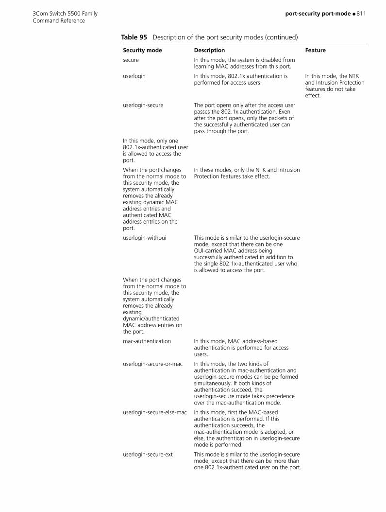
3Com Switch 5500 Family port-security port-mode ● 811 Command Reference
secure In this mode, the system is disabled from learning MAC addresses from this port.
userlogin In this mode, 802.1x authentication is performed for access users.
In this mode, the NTK and Intrusion Protection features do not take effect.
userlogin-secure The port opens only after the access user passes the 802.1x authentication. Even after the port opens, only the packets of the successfully authenticated user can pass through the port.
In this mode, only one 802.1x-authenticated user is allowed to access the port.
When the port changes from the normal mode to this security mode, the system automatically removes the already existing dynamic MAC address entries and authenticated MAC address entries on the port.
In these modes, only the NTK and Intrusion Protection features take effect.
userlogin-withoui This mode is similar to the userlogin-secure mode, except that there can be one OUI-carried MAC address being successfully authenticated in addition to the single 802.1x-authenticated user who is allowed to access the port.
When the port changes from the normal mode to this security mode, the system automatically removes the already existing dynamic/authenticated MAC address entries on the port.
mac-authentication In this mode, MAC address-based authentication is performed for access users.
userlogin-secure-or-mac In this mode, the two kinds of authentication in mac-authentication and userlogin-secure modes can be performed simultaneously. If both kinds of authentication succeed, the userlogin-secure mode takes precedence over the mac-authentication mode.
userlogin-secure-else-mac In this mode, first the MAC-based authentication is performed. If this authentication succeeds, the mac-authentication mode is adopted, or else, the authentication in userlogin-secure mode is performed.
userlogin-secure-ext This mode is similar to the userlogin-secure mode, except that there can be more than one 802.1x-authenticated user on the port.
Table 95 Description of the port security modes (continued)
Security mode Description Feature

812 ● port-security port-mode 3Com Switch 5500 Family Command Reference
userlogin-secure-or-mac-ext
This mode is similar to the userlogin-secure-or-mac mode, except that there can be more than one 802.1x-authenticated user on the port.
userlogin-secure-else-mac-ext
This mode is similar to the userlogin-secure-else-mac mode, except that there can be more than one 802.1x-authenticated user on the port.
Table 95 Description of the port security modes (continued)
Security mode Description Feature

3Com Switch 5500 Family port-security timer disableport ● 813 Command Reference
port-security timer disableport
Purpose Use the port-security timer disableport command to set the time during which the system temporarily disables a port.
Use undo port-security timer disableport command restore the default time.
Syntax port-security timer disableport timer
undo port-security timer disableport
Parameters timer Valid values for this argument are 20 to 300. If not specified, the default is 20 seconds.
Example Set the time during which the system temporarily disables a port to 50 seconds.
<S5500> system-view[S5500] port-security timer disableport 50
View This command can be used in the following views:
■ System view
Description The time set by the port-security timer disableport command takes effect when the disableport-temporarily mode is set by the port-security intrusion-mode command.

814 ● port-security trap 3Com Switch 5500 Family Command Reference
port-security trap
Purpose Use the port-security trap command to enable the sending of the specified type(s) of trap messages.
Use the undo port-security trap command to disable the sending of the specified type(s) of trap messages.
Syntax port-security trap { addresslearned | intrusion | dot1xlogon | dot1xlogoff | dot1xlogfailure | ralmlogon | ralmlogoff | ralmlogfailure }*
undo port-security trap { addresslearned | intrusion | dot1xlogon | dot1xlogoff | dot1xlogfailure | ralmlogon | ralmlogoff | ralmlogfailure }*
Parameters addresslearned Enables/disables the sending of MAC address learning trap messages.
intrusion Enables/disables the sending of intrusion packet discovery trap messages.
dot1xlogon Enables/disables the sending of 802.1x user logon trap messages.
dot1xlogoff Enables/disables the sending of 802.1x user logoff trap messages.
dot1xlogfailure Enables/disables the sending of 802.1x user authentication failure trap messages.
ralmlogon Enables/disables the sending of RALM user logon trap messages.
ralmlogoff Enables/disables the sending of RALM user logoff trap messages.
ralmlogfailure Enables/disables the sending of RALM user authentication failure trap messages.
RADIUS authenticated login using MAC-address (RALM) refers to MAC address-based RADIUS authentication.
Default By default, the system disables the sending of any types of trap messages.
Example Enter system view.
<S5500> system-view
Allow the sending of the intrusion packet discovery trap messages.
[S5500] port-security trap intrusion

3Com Switch 5500 Family port-security trap ● 815 Command Reference
View This command can be used in the following views:
■ System view
Description This command is designed based on the Device Tracking feature. The Device Tracking feature enables the switch to send trap messages in case special data packets (generated by special actions such as illegal intrusion, and abnormal user logon/logoff) pass through a port for the convenience of network administrator to monitor these special actions.
816 ● port-tagged 3Com Switch 5500 Family Command Reference
port-tagged
Purpose Use the port-tagged command to configure VLAN check on the management device for the communication inside a cluster.
Use the undo port-tagged command to cancel VLAN check on the management device for the communication inside a cluster.
Syntax port-tagged management-vlan
undo port-tagged
Parameters None
Default By default, VLAN check is performed.
Example Configure VLAN check for the communication inside a cluster.
<aaa_0.S5500>system-viewSystem View: return to User View with Ctrl+Z.[aaa_0.S5500]cluster[aaa_0.S5500-cluster] port-tagged management-vlan
View This command can be used in the following views:
■ Cluster view
Description Cluster packets are often forwarded inside the management VLAN only. Any configuration error (for example, the member port connected to the management device is set as a port outside the management VLAN) will cause communication failure between the management and member devices. To avoid such problem, you can configure VLAN check on the management device. This enables member devices to automatically add the connection port into the management VLAN, thus guarantees normal communication between the management and member devices.

3Com Switch 5500 Family port trunk permit vlan ● 817 Command Reference
port trunk permit vlan
Purpose Use the port trunk permit vlan command to add a trunk port to one VLAN, a selection of VLANs or all VLANs.
Use the undo port trunk permit vlan command to remove a trunk port from one VLAN, a selection of VLANs or all VLANs.
Syntax port trunk permit vlan {vlan_id_list | all}
undo port trunk permit vlan {vlan_id_list| all}
Parameters vlan_id Specifies a VLAN ID, or more than one VLAN ID. Valid values are 2 to 4094. The trunk port will be added to the specified VLANs. This can be a single VLAN, a series of individual VLANs separated by a space, or the first VLAN in a range of VLANs. If this is the first VLAN in a range use the last_vlan_id parameter to indicate the last VLAN in the range (vlan_id to last_vlan_id).
You can enter up to ten vlan_id parameters at one port trunk permit vlan command.
all Adds the trunk port to all VLANs.
Example To add the trunk port Ethernet1/0/1 to VLAN 2, VLAN 4 and all VLANs in the range 50-100, enter the following:
<SW5500>system-viewSystem View: return to User View with Ctrl+Z.[SW5500]interface ethernet 1/0/1[SW5500-Ethernet1/0/1]port link-type trunk[SW5500-Ethernet1/0/1]port trunk permit vlan 2 4 50 to 100Please wait... Done.[SW5500-Ethernet1/0/1]
View This command can be used in the following views:
■ Ethernet Port view
Description A trunk port can belong to multiple VLANs. If the port trunk permit vlan command is used many times, then the VLAN enabled to pass on trunk port is the set of these vlan_id_list.
Related Command port link-type
818 ● port trunk pvid vlan 3Com Switch 5500 Family Command Reference
port trunk pvid vlan
Purpose Use the port trunk pvid vlan command to configure the default VLAN ID for a trunk port.
Use the undo port trunk pvid command to restore the default VLAN ID for a trunk port.
Syntax port trunk pvid vlan vlan_id
undo port trunk pvid
Parameters vlan_id Specifies a VLAN ID. Valid values are 2 to 4094, as defined in IEEE802.1Q. This is the VLAN that you want to be the default VLAN for a trunk port. If not specified, the default is 1.
Default The default VLAN ID of local trunk port should be consistent with that of the peer one, otherwise packets cannot be properly transmitted.
Example To configure the trunk port Ethernet1/0/1 to the default VLAN of 100, enter the following:
<SW5500>system-viewSystem View: return to User View with Ctrl+Z.[SW5500]interface ethernet 1/0/1[SW5500-Ethernet1/0/1]port link-type trunk[SW5500-Ethernet1/0/1]port trunk pvid vlan 100[SW5500-Ethernet1/0/1]
View This command can be used in the following views:
■ Ethernet Port view
Related Command port link-type
3Com Switch 5500 Family preference ● 819 Command Reference
preference
Purpose Using the preference command, you can configure the OSPF protocol route preference.
Using the undo preference command, you can restore the default value of the OSPF protocol route.
Syntax preference [ ase ] value
undo preference [ ase ]
Parameters value Specifies the OSPF protocol route preference. Valid values are 1 to 255.
ase Indicates the preference of an imported external route of the AS.
Default By default, the preference of an OSPF protocol internal route is 10 and the preference of an external route is 150.
Example To set the preference of an imported external route of the AS to 160, enter the following:
<SW5500>system-viewSystem View: return to User View with Ctrl+Z.[SW5500]router id 1.1.1.1[SW5500]ospf[SW5500-ospf-1]preference ase 160
View This command can be used in the following views:
■ OSPF view
Description Because multiple dynamic routing protocols could be running on a router at any one time, priority needs to be assigned to each protocol. Using this command, you can set a default preference for each routing protocol. The protocol with the higher preference has priority.
820 ● preference 3Com Switch 5500 Family Command Reference
preference
Purpose Use the preference command to configure the route preference of RIP.
Use the undo preference command to restore the default preference.
Syntax preference value
undo preference
Parameters value Specifies the preference level. Valid values are 1 to 255. If not specified, the value is 100.
Default The default value of each routing protocol is determined by the specific routing policy. This “preference” determines the optimal route in the IP routing table. You can use this command to modify the RIP preference.
Example To specify an RIP preference of 20, enter the following:
<SW5500>system-viewSystem View: return to User View with Ctrl+Z.[SW5500]rip[SW5500-rip]preference 20
View This command can be used in the following views:
■ RIP view
3Com Switch 5500 Family primary accounting ● 821 Command Reference
primary accounting
Purpose Use the primary accounting command to configure a primary TACACS accounting server.
Use the undo primary accounting command to delete the configured primary TACACS accounting server.
Syntax primary accounting ip-address [ port ]
undo primary accounting
Parameters ip-address IP address of the server, a valid unicast address in dotted decimal format.
port Port number of the server. Valid values are 1 to 65535. If not specified, the default is 49.
Example Configure a primary accounting server.
[S5500] hwtacacs scheme test1[S5500-hwtacacs-test1] primary accounting 10.163.155.12 49
View This command can be used in the following views:
■ HWTACACS view
Description You are not allowed to assign the same IP address to both primary and secondary accounting servers.
You can configure only one primary accounting server in a HWTACACS scheme. If you repeatedly use this command, the latest configuration replaces the previous one.
You can remove an accounting server only when it is not being used by any active TCP connections, and the removal impacts only packets forwarded afterwards.

822 ● primary authentication 3Com Switch 5500 Family Command Reference
primary authentication
Purpose Use the primary authentication command to configure a primary TACACS authentication server.
Use the undo primary authentication command to delete the configured authentication server.
Syntax primary authentication ip-address [ port ]
undo primary authentication
Parameters ip-address IP address of the server, a valid unicast address in dotted decimal format.
port Port number of the server. Valid values are 1 to 65535. If not specified, the default is 49.
Example Configure a primary authentication server.
[S5500] hwtacacs scheme test1[S5500-hwtacacs-test1] primary authentication 10.163.155.13 49
View This command can be used in the following views:
■ HWTACACS view
Description You are not allowed to assign the same IP address to both primary and secondary authentication servers.
You can configure only one primary authentication server in a HWTACACS scheme. If you repeatedly use this command, the latest configuration replaces the previous one.
You can remove an authentication server only when it is not being used by any active TCP connections, and the removal impacts only packets forwarded afterwards.
Related Command display hwtacacs
3Com Switch 5500 Family primary authorization ● 823 Command Reference
primary authorization
Purpose Use the primary authorization command to configure a primary TACACS authorization server.
Use the undo primary authorization command to delete the configured primary authorization server.
Syntax primary authorization ip-address [ port ]
undo primary authorization
Parameters ip-address IP address of the server, a valid unicast address in dotted decimal format.
port Port number of the server. Valid values are 1 to 65535. If not specified, the default is 49.
Example Configure a primary authorization server.
[S5500] hwtacacs scheme test1[S5500-hwtacacs-test1] primary authorization 10.163.155.13 49
View This command can be used in the following views:
■ HWTACACS view
Description You are not allowed to assign the same IP address to both primary and secondary authorization servers.
You can configure only one primary authorization server in a HWTACACS scheme. If you repeatedly use this command, the latest configuration replaces the previous one.
You can remove an authorization server only when it is not being used by any active TCP connections, and the removal impacts only packets forwarded afterwards.
Related Command display hwtacacs
824 ● priority 3Com Switch 5500 Family Command Reference
priority
Purpose Use the priority command to configure the priority of Ethernet port.
Use the undo priority command to restore the default port priority.
Syntax priority priority-level
undo priority
Parameters priority-level Specifies the priority level of the port. Valid values are 0 to 7. If not specified, the default priority level of the port is 0.
Example Set the priority of Ethernet1/0/1 port to 7.
<SW5500>system-viewSystem View: return to User View with Ctrl+Z[SW5500]interface Ethernet 1/0/1[SW5500-Ethernet1/0/1]priority 7[SW5500-Ethernet1/0/1]
View This command can be used in the following views:
■ Ethernet Port view
Description The Switch replaces the 802.1p priority carried by a packet with the port priority that is defined.
Every port on the Switch supports eight packet egress queues. The Switch puts the packets into different egress queues according to their priorities.
When transmitting a packet, the Switch replaces the packet’s 802.1p priority with the priority of the received port, according to which the packet will be put into the corresponding egress queue.

3Com Switch 5500 Family priority trust ● 825 Command Reference
priority trust
Purpose Use the priority trust command to configure the system to trust the packet’s 802.1p priority and not replace the 802.1p priorities carried by the packets with the port priority.
Use undo priority command to configure the system not to trust the packet 802.1p priority.
Syntax priority trust
undo priority
Parameters None
Default By default, the system replaces the 802.1p priority carried by a packet with the port priority.
Example Configure the system to trust the packet 802.1p priority and not replace the 802.1p priorities carried by the packets with the port priority.
<SW5500>system-viewSystem View: return to User View with Ctrl+Z[SW5500]interface Ethernet 1/0/1[SW5500-Ethernet1/0/1]priority trust [SW5500-Ethernet1/0/1]
View This command can be used in the following views:
■ Ethernet Port view
Related Command priority
826 ● protocol inbound 3Com Switch 5500 Family Command Reference
protocol inbound
Purpose Use the protocol inbound command to configure the protocols supported in the current user interface.
Syntax protocol inbound { all | ssh | telnet }
Parameters all Supports all protocols, including Telnet and SSH.
ssh Supports only SSH.
telnet Supports only Telnet.
Default By default, both SSH and Telnet are supported.
Example Configure vty0 through vty4 to support SSH only.
<S5500> system-view[S5500] user-interface vty 0 4[S5500-ui-vty0-4] protocol inbound ssh
View This command can be used in the following views:
■ VTY User Interface view
Description After you use this command with SSH enabled, your configuration cannot take effect till next login if no RSA key pair is configured.
CAUTION:
■ When SSH protocol is specified, to ensure a successful login, you must configure the AAA authentication using the authentication-mode scheme command.
■ The protocol inbound ssh configuration fails if you configured authentication-mode password and authentication-mode none. When you configured SSH protocol successfully for the user interface, then you cannot configure authentication-mode password and authentication-mode none any more.

3Com Switch 5500 Family protocol-priority protocol-type ● 827 Command Reference
protocol-priority protocol-type
Purpose Use the protocol-priority command to set the global traffic priority that applies to a given protocol.
Use the undo protocol-priority command to remove such a configuration.
Syntax protocol-priority protocol-type protocol-type { ip-precedence ip-precedence | dscp dscp-value }
undo protocol-priority protocol-type protocol-type
Parameters protocol-type protocol-type Represents the protocol type, currently only supports
OSPF, TELNET, SNMP, ICMP (to be input in the form of strings in the command line).
ip-precedence ip-precedence IP priority. Valid values are 0 to 7.
dscp dscp-value DSCP priority. Valid values are 0 to 63.
Example Set the IP priority of OSPF protocol to be 3.
<S5500> system-viewSystem View: return to User View with Ctrl+Z.[S5500] protocol-priority protocol-type OSPF ip-precedence 3
View This command can be used in the following views:
■ System view
828 ● protocol-vlan 3Com Switch 5500 Family Command Reference
protocol-vlan
Purpose Use the protocol-vlan command to specify a VLAN is a specified type of protocol-based VLAN.
Use the undo protocol-vlan command to cancel the configuration.
Syntax protocol-vlan [ procotol-index ] { at | ip | ipx { ethernetii | llc | raw | snap } | mode { ethernetii etype etype-id | llc { dsap dsap-id [ ssap ssap-id ] | ssap ssap-id } | snap etype etype-id }
undo protocol-vlan { protocol-index [ to protocol-end ] | all }
Parameters at Specifies the VLAN is an AT-based VLAN. (AT stands for AppleTalk.)
ip Specifies the VLAN is an IP-based VLAN.
ipx Specifies the VLAN is an IPX-based VLAN. The ethernetii, llc, raw and snap keywords specify the four IPX encapsulation types.
mode Specifies the VLAN is based on other protocols.
ethernetii Specifies the VLAN is an EthernetII-based VLAN.
etype-id The Ethernet type of the inbound packets. Valid values for this argument are from 600 to FFFF.
llc Specifies the VLAN is based on logic link control protocols.
dsap-id Destination service access point. Valid values for this argument are from 0 to FF.
ssap-id Source service access point. Valid values for this argument are from 0 to FF.
snap Specifies that the VLAN is a SNAP-based VLAN. (SNAP is short for sub-network access protocol.)
etype-id The Ethernet type of inbound packets. Valid values for this argument are from 600 to FFFF.
protocol-index Beginning protocol index. Valid values are from 0 to 4. This argument needs to be less than or equal to the end protocol index. If you do not specify this argument, the beginning protocol index will be determined by the system.
protocol-end End protocol index. Valid values are from 0 to 4. This argument needs to be larger than or equal to the protocol-index argument.
all Specifies all protocol indexes.

3Com Switch 5500 Family protocol-vlan ● 829 Command Reference
Example Specify VLAN3 is an IP-based VLAN.
<S5500> system-viewSystem View: return to User View with Ctrl+Z.[S5500] vlan 3[S5500-vlan3] protocol-vlan ip
View This command can be used in the following views:
■ VLAN view
Related Command display protocol-vlan vlan

830 ● public-key-code begin 3Com Switch 5500 Family Command Reference
public-key-code begin
Purpose Use the public-key-code begin command to enter public key edit view and input the client public key.
Syntax public-key-code begin
Parameters None
Example Enter public key edit view and input client public keys.
<S5500> system-view[S5500] rsa peer-public-key 3Com003[S5500-rsa-public-key] public-key-code begin[S5500-key-code] 308186028180739A291ABDA704F5D93DC8FDF84C427463[S5500-key-code] 1991C164B0DF178C55FA833591C7D47D5381D09CE82913[S5500-key-code] D7EDF9C08511D83CA4ED2B30B809808EB0D1F52D045DE4[S5500-key-code] 0861B74A0E135523CCD74CAC61F8E58C452B2F3F2DA0DC[S5500-key-code] C48E3306367FE187BDD944018B3B69F3CBB0A573202C16[S5500-key-code] BB2FC1ACF3EC8F828D55A36F1CDDC4BB45504F020125[S5500-key-code] public-key-code end[S5500-rsa-public-key]
View This command can be used in the following views:
■ Public Key Edit view
Description You can key in a blank space between characters (since the system can remove the blank space automatically), or press <Enter> to continue your input at the next line. But the public key, which is generated randomly by the SSH 2.0-supported client software, should be composed of hexadecimal characters.
Related Commands ■ public-key-code end
■ rsa peer-public-key

3Com Switch 5500 Family public-key-code begin ● 831 Command Reference
public-key-code begin
Purpose Use the public-key-code begin command to enter public key edit view and set server public keys.
Syntax public-key-code begin
Parameters None
Example Enter public key edit view and set server public keys.
<S5500> system-view[S5500] rsa peer-public-key 3Com003[S5500-rsa-public-key] public-key-code begin[S5500-key-code] 308186028180739A291ABDA704F5D93DC8FDF84C427463[S5500-key-code] 1991C164B0DF178C55FA833591C7D47D5381D09CE82913[S5500-key-code] D7EDF9C08511D83CA4ED2B30B809808EB0D1F52D045DE4[S5500-key-code] 0861B74A0E135523CCD74CAC61F8E58C452B2F3F2DA0DC[S5500-key-code] C48E3306367FE187BDD944018B3B69F3CBB0A573202C16[S5500-key-code] BB2FC1ACF3EC8F828D55A36F1CDDC4BB45504F020125[S5500-key-code] public-key-code end[S5500-rsa-public-key]
View This command can be used in the following views:
■ Public Key Edit view
Description You can key in a blank space between characters (since the system can remove the blank space automatically), or press <Enter> to continue your input at the next line. But the public key, which are generated randomly after you use the rsa local-key-pair create command on the server, should be composed of hexadecimal characters.
Related Commands ■ public-key-code end
■ rsa local-key-pair create
■ rsa peer-public-key
832 ● public-key-code end 3Com Switch 5500 Family Command Reference
public-key-code end
Purpose Use the public-key-code end command to return from public key edit view to public key view and save the public keys you set.
Syntax public-key-code end
Parameters None
Example Exit from public key edit view and save the public keys.
<S5500> system-view[S5500]rsa peer-public-key zhangshan[S5500-rsa-public-key]public-key-code begin[S5500-rsa-key-code] public-key-code end[S5500-rsa-public-key]
View This command can be used in the following views:
■ Public Key Edit view
Description After you use this command to terminate the public key editing, public key validity will be checked before the keys are saved. If there are illegal characters in the keys, the prompt will be given and the keys will be discarded. Your configuration this time fails. If the keys are valid, they will be saved in the public key list of the client.
Related Command ■ public-key-code begin
■ rsa peer-public-key
3Com Switch 5500 Family put ● 833 Command Reference
put
Purpose Use the put command to upload a local file to the remote SFTP server.
If no name is specified for the file to be saved on the remote SFTP server, the name of the source file is used.
Syntax put local-file [ remote-file ]
Parameters local-file Name of the source file at the local end.
remote-file Name assigned to the file to be saved on the remote SFTP server.
Example Upload local file temp.c to the remote SFTP server and save it with the name temp1.c.
sftp-client> put temp.c temp1.c
View This command can be used in the following views:
■ SFTP Client view

834 ● pwd 3Com Switch 5500 Family Command Reference
pwd
Purpose Use the pwd command to display the current directory on the SFTP server.
Syntax pwd
Parameters None
Example Display the current directory on the SFTP server.
sftp-client> pwdflash:/
View This command can be used in the following views:
■ SFTP Client view
3Com Switch 5500 Family queue-scheduler ● 835 Command Reference
queue-scheduler
Purpose Use the queue-scheduler command to configure queue scheduling mode.
Use the undo queue-scheduler command to restore the default value.
Syntax queue-scheduler { wfq queue1-width queue2- width queue3- width queue4- width queue5-width queue6-width queue7-width queue8-width | wrr queue1-weight queue2-weight queue3-weight queue4-weight queue5-weight queue6-weight queue7-weight queue8-weight }
undo queue-scheduler
Parameters wfq queue1-width queue2- width queue3- width queue4- width queue5-width queue6-width queue7-width queue8-width Indicates that the queue uses Weighted Fair Queue
scheduling. queue1-weight: the weight of queue 1, the percentage allocated by bandwidth; queue2-weight: the weight of queue 2, and so on.
wrr queue1-weight queue2-weight queue3-weight queue4-weight queue5-weight queue6-weight queue7-weight queue8-weight Indicates that the queue uses weight round robin
(WWR) scheduling. queue1-weight: the weight of queue 1, the percentage allocated by bandwidth; queue2-weight: the weight of queue 2, and so on.
queue-scheduler strict priority SP divides the queue of port into up to 8, from
high-priority queue to low-priority queue. During the progress of packet delivery from the queues, packets are picked up from each queue strictly following the priority order from high to low. When the higher-priority queue is empty it will send the packets in the lower-priority group. SP has the drawback that when congestion occurs, if there are many packets queuing in the higher-priority queue, it will require a long time to transmit these packets of higher service priority while the messages in the lower-priority queue are continuously set aside without delivery.
Default By default, WRR algorithm is selected for all outbound queues at a port.

836 ● queue-scheduler 3Com Switch 5500 Family Command Reference
Example To set WRR as the port queue scheduling mode, enter the following:
<SW5500>system-viewSystem View: return to User View with Ctrl+Z[SW5500]interface Ethernet 1/0/1[SW5500-Ethernet1/0/1]queue-scheduler wrr 1 2 3 4 5 6 7 8[SW5500-Ethernet1/0/1]
View This command can be used in the following views:
■ Ethernet Port view
Description The queue weight is based on bytes. For example, if the weight of queues 1, 2, 3, 4, 5, 6, 7, 8 is respectively as 1, 2, 3, 4, 5, 6, 7, 8, then among every 36 bytes in process, 1 bytes from queue 1, 2 bytes from queue 2, 3 bytes from queue 3 and 4 bytes from queue 4, 5 bytes from queue 5, 6 bytes from queue 6, 7 bytes from queue 7 and 8 bytes from queue 8.
Related Command display queue-scheduler
3Com Switch 5500 Family quit ● 837 Command Reference
quit
Purpose Use the quit command to terminate the connection to the remote SSH server.
Syntax quit
Parameters None
Example Terminate the connection to the remote SSH server.
<S5500> quit
View This command can be used in the following views:
■ User view

838 ● quit 3Com Switch 5500 Family Command Reference
quit
Purpose Use the quit command to terminate the connection to the remote SFTP server and exit to system view.
Syntax quit
Parameters None
Example Terminate the connection to the remote SFTP server.
sftp-client> quit[S5500]
View This command can be used in the following views:
■ SFTP Client view
Description This command has the same function as the bye and exit commands.
3Com Switch 5500 Family qos cos-local-precedence-map ● 839 Command Reference
qos cos-local-precedence-map
Purpose Use the qos cos-local-precedence-map command to configure “CoS Local-precedence” mapping table
Use the undo qos cos-local-precedence-map command to restore its default values.
Syntax qos cos-local-precedence-map cos0-map-local-prec cos1-map-local-prec cos2-map-local-prec cos3-map-local-prec cos4-map-local-prec cos5-map-local-prec cos6-map-local-prec cos7-map-local-prec
undo qos cos-local-precedence-map
Parameters cos0-map-local-prec CoS 0 -> Local precedence (queue) mapping value, in the range of 0~7.
cos1-map-local-prec CoS 1 -> Local precedence (queue) mapping value, in the range of 0~7.
cos2-map-local-prec CoS 2 -> Local precedence (queue) mapping value, in the range of 0~7.
cos3-map-local-prec CoS 3 -> Local precedence (queue) mapping value, in the range of 0~7.
cos4-map-local-prec CoS 4 -> Local precedence (queue) mapping value, in the range of 0~7.
cos5-map-local-prec CoS 5 -> Local precedence (queue) mapping value, in the range of 0~7.
cos6-map-local-prec CoS 6 -> Local precedence (queue) mapping value, in the range of 0~7.
cos7-map-local-prec CoS 7 -> Local precedence (queue) mapping value, in the range of 0~7.
Example Configure CoS and Local Precedence table.
<SW5500>system-viewSystem View: return to User View with Ctrl+Z[SW5500]qos cos-local-precedence-map 0 1 2 3 4 5 6 7[SW5500]

840 ● qos cos-local-precedence-map 3Com Switch 5500 Family Command Reference
The following is the configured "CoS Local-precedence” mapping table.
View This command can be used in the following views:
■ System view
Description This will map a CoS value to a specific local precedence (queue). Note that traffic which has been assigned a local precedence via QOS will also be assigned to the same queue.
The following is the default CoS and Local Precedence table.
Table 96 Default configure CoS and Local-precedence table
Cos and Local Precedence Value Local Precedence Queue
0 0
1 1
2 2
3 3
4 4
5 5
6 6
7 7
Table 97 Default CoS and Local-precedence table
Cos and Local Precedence Value Local Precedence Queue
0 2
1 0
2 1
3 3
4 4
5 5
6 6
7 7

3Com Switch 5500 Family qos-profile ● 841 Command Reference
qos-profile
Purpose Use the qos-profile command to create a QoS profile and enter the corresponding view. For an existing profile, you can directly enter the corresponding view.
Use the undo qos-profile command to delete a QoS profile.
Syntax qos-profile profile-name
undo qos-profile profile-name
Parameters profile-name QoS profile name, consisting of a string of one to 32 characters, starting with letters [a-z, A-Z] and excluding all, interface, and user which are reserved as keywords.
Example To create QoS profile student, enter the following:
<SW5500>system-viewSystem View: return to User View with Ctrl+Z[SW5500] qos-profile student[SW5500-qos-profilestudent]
View This command can be used in the following views:
■ System view
Description You cannot delete the specific QoS profile that has been applied to the port.
842 ● radius nas-ip 3Com Switch 5500 Family Command Reference
radius nas-ip
Purpose Use the radius nas-ip command to specify the source address of the RADIUS packet sent from NAS.
Use the undo radius nas-ip command to restore the default setting.
Syntax radius nas-ip ip-address
undo radius nas-ip
Parameters ip-address IP address in dotted decimal format.
Default By default, the source address is not specified, that is, the address of the interface sending the packet serves as the source address.
Example To configure the Switch to send RADIUS packets from 129.10.10.1, enter the following:
<SW5500>system-viewSystem View: return to User View with Ctrl+Z.[SW5500]radius nas-ip 129.10.10.1
View This command can be used in the following views:
■ System view
Description By specifying the source address of the RADIUS packet, you can avoid unreachable packets as returned from the server upon interface failure. The source address is normally recommended to be a loopback interface address.
This command specifies only one source address; therefore, the newly configured source address may overwrite the original one.
3Com Switch 5500 Family radius-scheme ● 843 Command Reference
radius-scheme
Purpose Use the radius-scheme command to configure the RADIUS scheme used by the current ISP domain.
Syntax radius-scheme radius-scheme-name
Parameters radius-scheme-name Specifies a RADIUS scheme, consisting of a character string not exceeding 32 characters.
Example The following example designates the current ISP domain, marlboro.net, to use the RADIUS server, Radserver.
<SW5500>system-viewSystem View: return to User View with Ctrl+Z.[SW5500]domain marlboro.net[SW5500-isp-marlboro.net]radius-scheme Radserver
View This command can be used in the following views:
■ ISP Domain view
Description This command is used to specify the RADIUS scheme for the current ISP domain. The specified RADIUS scheme shall have been created.
Related Commands ■ display radius

844 ● radius scheme 3Com Switch 5500 Family Command Reference
radius scheme
Purpose Use the radius scheme command to configure a RADIUS scheme group and enter its view.
Use the undo radius scheme command to delete the specified RADIUS scheme.
Syntax radius scheme radius-scheme-name
undo radius scheme radius-scheme-name
Parameters radius-scheme-name Specifies the Radius server name, consisting of a character string not exceeding 32 characters.
Default A default RADIUS scheme named system has been created in the system. The attributes of system are all default values.
Example To create a RADIUS scheme named “3Com” and enter its view, enter the following:
<SW5500>system-viewSystem View: return to User View with Ctrl+Z.[SW5500]radius scheme 3ComNew Radius scheme[SW5500-radius-3Com]
View This command can be used in the following views:
■ System view
Description RADIUS protocol configuration is performed on a per-RADIUS-scheme basis. Every RADIUS scheme shall at least have the specified IP address and UDP port number of the RADIUS authentication/authorization/accounting server and some necessary parameters exchanged with the RADIUS client end (Switch). It is necessary to create the RADIUS scheme and enter its view before performing other RADIUS protocol configurations.
A RADIUS scheme can be used by several ISP domains at the same time. You can configure up to 16 RADIUS schemes, including the default RADIUS scheme named as System.
Although undo radius scheme can remove a specified RADIUS scheme, the default one cannot be removed. Note that a scheme currently in use by the online user cannot be removed.
Related Commands ■ key
■ display radius

3Com Switch 5500 Family radius scheme ● 845 Command Reference
■ radius-scheme
■ retry
■ retry realtime-accounting
■ retry stop-accounting
■ server-type
■ state
■ stop-accounting-buffer enable
■ timer realtime-accounting
■ user-name-format

846 ● reboot 3Com Switch 5500 Family Command Reference
reboot
Purpose Use the reboot command to restart an Ethernet switch.
Syntax reboot [ unit unit-id ]
Parameters unit-id Unit ID of a switch.
Example Directly restart the switch without saving the current configuration.
<S5500> reboot This will reboot device. Continue? [Y/N] y Start to check configuration with next startup configuration file, please wait...... This command will reboot the device. Current configuration may be lost in nextstartup if you continue. Continue? [Y/N] y#Apr 2 00:05:57:155 2000 S5500 COMMONSY/5/REBOOT:- 1 - Reboot Fabric by command.
<S5500>%Apr 2 00:06:01:148 2000 S5500 DEV/5/DEV_LOG:- 1 -Switch is rebooted.Starting......
Description The system will check whether there is any configuration change before it restarts, and will ask whether you want to proceed or not if there is any change, to prevent you from losing your original configuration due to forgetting after the restart.
View This command can be used in the following views:
■ User view
3Com Switch 5500 Family reboot member ● 847 Command Reference
reboot member
Purpose Use the reboot member command to reset a specified member device on the management device.
Syntax reboot member { member-number | mac-address H-H-H } [ eraseflash ]
Parameters member-number Cluster member number.
mac-address H-H-H MAC address of the member device to be reset.
eraseflash Deletes the configuration file when resetting the member device.
Example Reset cluster member 2.
<aaa_0.S5500>system-viewSystem View: return to User View with Ctrl+Z.[aaa_0.S5500]cluster[aaa_0.S5500-cluster] reboot member 2
View This command can be used in the following views:
■ Cluster view
Description Communication between the management and member devices may be interrupted due to some configuration errors. Through the remote control function of member devices, you can control them remotely on the management device. For example, you can delete the booting configuration file and reset the member device, and thus restore normal communication between the management and member devices.
When using the reboot member command, you can decide whether to delete the configuration file when the member device is resetting with argument eraseflash.
848 ● region-name 3Com Switch 5500 Family Command Reference
region-name
Purpose Use the region-name command to assign an MST region name to a switch.
Use the undo region-name command to restore the default MST region name.
Syntax region-name name
undo region-name
Parameters name MST region name for a switch, consisting of a string from 1 to 32 characters long.
Default The default MST region name of a switch is its MAC address.
MST region name, along with MST region VLAN mapping table and MSTP revision level, determines the MST region to which a switch belongs.
Example Configure the MST region name of the switch to be hello.
<S5500> system-view System View: return to User View with Ctrl+Z.[S5500] stp region-configuration [S5500-mst-region] region-name hello
View This command can be used in the following views:
■ MST Region view
Related Commands ■ active region-configuration
■ check region-configuration
■ instance
■ revision-level
■ vlan-mapping modulo
3Com Switch 5500 Family register-policy ● 849 Command Reference
register-policy
Purpose Use the register-policy command to configure a RP to filter the register messages sent by the DR in the PIM-SM network and to accept the specified messages only.
Use the undo register-policy command to remove the configured message filtering.
Syntax register-policy acl-number
undo register-policy
Parameters acl-number Number of IP advanced ACL, defining the rule of filtering the source and group addresses. Valid values are 3000 to 3999.
Example If the local device is the RP in the network, use the following command to only accept multicast message register of the source sending multicast address in the range of 225.1.0.0/16 on network segment 10.10.0.0/16.
<SW5500> system-viewSystem View: return to User View with Ctrl+Z[SW5500] acl number 3010[SW5500-acl-adv-3010] rule permit ip source 10.10.0.0 0.0.255.255 destination 225.1.0.0 0.0.255.255[SW5500-acl-adv-3010] quit[SW5500] pim[SW5500-pim] register-policy 3010
View This command can be used in the following views:
■ PIM view
850 ● remote-ping 3Com Switch 5500 Family Command Reference
remote-ping
Purpose Use the remote-ping command to specify remote-ping test class.
Syntax remote-ping [ count | destination-ip | display | frequency | msdp-tracert | mtracert | ping | quit ]
Parameters count Specifies remote-ping probe number in one test.
destination-ip Specifies remote-ping class destination ip address.
display Displays current system information.
frequency Specifies remote-ping interval time between two remote-ping tests.
msdp-tracert Specifies MSDP trace route to source RP.
mtracert Traces route to multicast source.
ping Ping function.
quit Exits from current command view.
Example [5500-EI]remote-ping
View This command can be used in the following views:
■ System view
Description Remote-ping is a network diagnostic tool used to test the performance of protocols (only ICMP by far) operating on network. It is an enhanced alternative to the ping command.
Remote-ping test group is a set of remote-ping test parameters. A test group contains several test parameters and is uniquely identified by an administrator name plus a test tag.
You can perform an remote-ping test after creating a test group and configuring the test parameters.
Different from the ping command, remote-ping does not display the round trip time (RTT) and timeout status of each packet on the console terminal in real time. You need to execute the display remote-ping command to view the statistic results of your remote-ping test operation. remote-ping allows administrators to set the parameters of remote-ping test groups and start remote-ping test operations.

3Com Switch 5500 Family remote-ping ● 851 Command Reference
Related Command display remote-ping
ping
tracert

852 ● remote-ping-agent enable 3Com Switch 5500 Family Command Reference
remote-ping-agent enable
Purpose Use the remote-ping-agent enable command to enable remote-ping client.
Use the undo remote-ping-agent enable command to disable remote-ping client.
Syntax remote-ping-agent enable
undo remote-ping-agent enable
Parameters None
Example Enable remote-ping client.
[S5500] remote-ping-agent enable
View This command can be used in the following views:
■ System view
Description You can perform a test only after the remote-ping client function is enabled.

3Com Switch 5500 Family remote-probe vlan ● 853 Command Reference
remote-probe vlan
Purpose Use the remote-probe vlan enable command to enable the remote-probe port mirroring on the VLAN of a switch.
Use the undo remote-probe vlan enable command to disable the remote-probe port mirroring.
Syntax remote-probe vlan enable
undo remote-probe vlan enable
Parameters None
Example Configure VLAN 5 to be remote-probe VLAN.
<S5500> system-viewSystem View: return to User View with Ctrl+Z.[S5500] vlan 5[S5500-vlan5] remote-probe vlan enable
View This command can be used in the following views:
■ VLAN view
854 ● remotehelp 3Com Switch 5500 Family Command Reference
remotehelp
Purpose Use the remotehelp command to display help information about the FTP protocol command.
Syntax remotehelp [ protocol-command ]
Parameters protocol-command FTP protocol command.
Example Show the syntax of the protocol command user.
<SW5500>ftp 1.1.1.1Trying ...Press CTRL+K to abortConnected.220 FTP service ready.User(none):hello331 Password required for hello.Password:230 User logged in [ftp]remotehelp user 214 Syntax: USER <sp> <username>[ftp]
View This command can be used in the following views:
■ FTP Client view

3Com Switch 5500 Family remove ● 855 Command Reference
remove
Purpose Use the remove command to delete the specified file from the server.
Syntax remove remote-file
Parameters remote-file Name of a file on the server.
Example Delete file temp.c from the server.
sftp-client> remove temp.c
View This command can be used in the following views:
■ SFTP Client view
Description This command has the same function as the delete command.

856 ● rename 3Com Switch 5500 Family Command Reference
rename
Purpose Use the rename command to change the name of the specified file on the SFTP server.
Syntax rename old name new name
Parameters old name Original file name.
new name New file name.
Example Change the name of file temp1 on the SFTP server to temp2.
sftp-client> rename temp1 temp2
View This command can be used in the following views:
■ SFTP Client view
3Com Switch 5500 Family reset ● 857 Command Reference
reset
Purpose Use the reset command to reset the system configuration parameters of RIP.
Syntax reset
Parameters None
Example Reset the RIP system.
<SW5500>system-viewSystem View: return to User View with Ctrl+Z.[SW5500]rip[SW5500-rip]reset
View This command can be used in the following views:
■ RIP view
Description When you need to re-configure parameters of RIP, this command can be used to restore to the default setting.
858 ● reset acl counter 3Com Switch 5500 Family Command Reference
reset acl counter
Purpose Use the reset acl counters command to reset the ACL statistics information to zero.
Syntax reset acl counter { all | acl-number }
Parameters all All ACLs.
acl-number Specifies the sequence number of an ACL.
Example Clear the statistics information of ACL 2000.
<SW5500>reset acl counters 2000
View This command can be used in the following views:
■ User view

3Com Switch 5500 Family reset arp ● 859 Command Reference
reset arp
Purpose Use the reset arp command to remove information that is no longer required from the ARP mapping table.
Use the reset arp command to clear all ARP entries. You are asked to confirm this entry.
Use the reset arp dynamic command to clear all dynamic ARP entries.
Use the reset arp static command to clear all static ARP entries.
Use the display arp interface command to clear all entries for the specified port.
Syntax reset arp [ dynamic | static | interface { interface_type interface_num | interface_name } ]
Parameters dynamic Clears the dynamic ARP mapping entries. Note that dynamic ARP entries start re-learning immediately.
static Clears the static ARP mapping entries. Note that static ARP entries are deleted permanently.
interface interface_type interface_num interface_name Clears the ARP mapping entries for the specified port.
Example To clear static ARP entries, enter the following:
<SW5500>reset arp static
View This command can be used in the following views:
■ User view
Description You can remove entries of a specified type, or from a specified port.
Related Command ■ arp static
■ display arp
860 ● reset counters interface 3Com Switch 5500 Family Command Reference
reset counters interface
Purpose Use the reset counters interface command to reset the statistical information on the port and count the related information again on the port for the user.
Syntax reset counters interface [ interface_type | interface_type interface_num | interface_name]
Parameters interface_type Specifies the port type.
interface_num Specifies the port number.
interface_name Specifies the port name in the interface_name= interface_type interface_num format.
For parameter description, refer to the interface command.
Example To reset statistical information on Ethernet1/0/1, enter the following:
<SW5500>reset counters interface ethernet1/0/1<SW5500>
View This command can be used in the following views:
■ User view
Description If you do not enter a port type, or port type and port number, information is cleared from all ports on the Switch. If only the port type is specified, all the information on ports of this type will be cleared. If both port type and port number are specified, the information on the dpecified port will be cleared. After 802.1x is enabled, the port information cannot be reset.

3Com Switch 5500 Family reset dhcp server conflict ● 861 Command Reference
reset dhcp server conflict
Purpose Use the reset dhcp server conflict command to clear address conflict statistics.
Syntax reset dhcp server conflict { all | ip ip-address }
Parameters ip ip-address Specifies an IP address, whose conflict statistics will be cleared.
all Clears all address conflict statistics.
Example Clear all address conflict statistics.
<S5500> reset dhcp server conflict all
View This command can be used in the following views:
■ User view
Description This command applies only to the S5500-EI series among Switch 5500-Series Switches.
Related Command display dhcp server conflict
862 ● reset dhcp server ip-in-use 3Com Switch 5500 Family Command Reference
reset dhcp server ip-in-use
Purpose Use the reset dhcp server ip-in-use command to clear the specified or all dynamic address binding information.
Syntax reset dhcp server ip-in-use { ip ip-address | pool [ pool-name ] | interface [ interface-type interface-number ] | all }
Parameters all Clears the dynamic address binding information about all IP addresses.
ip ip-address Clears the dynamic address binding information about a specified IP address.
pool [ pool-name ] Clears the dynamic address binding information about a specified address pool. The pool-name argument consists of a string from 1 to 35 characters long and is the name of an address pool. If you do not provide this argument, this command clears the dynamic address binding information about all global address pools.
interface [ interface-type interface-number ] Clears the dynamic address binding information about
a specified interface address pool. If you do not specify the interface-number argument, this command clears the dynamic address binding information about all interface address pools.
Example Clear the dynamic address binding information about the IP address 10.110.1.1.
<S5500> reset dhcp server ip-in-use ip 10.110.1.1
View This command can be used in the following views:
■ User view
Description This command applies only to the S5500-EI series among Switch 5500-Series Switches.
Related Command display dhcp server ip-in-use

3Com Switch 5500 Family reset dhcp server statistics ● 863 Command Reference
reset dhcp server statistics
Purpose Use the reset dhcp server statistics command to clear the statistics on a DHCP server, such as the number of global/interface address pools, the number of manually/automatically-bound or expired IP addresses, the number of DHCP unrecognized packets/request packets/response packets.
Syntax reset dhcp server statistics
Parameters None
Example Clear the statistics on a DHCP server.
<S5500> reset dhcp server statistics
View This command can be used in the following views:
■ User view
Description This command applies only to the S5500-EI series among Switch 5500-Series Switches.
Related Command display dhcp server statistics

864 ● reset dot1x statistics 3Com Switch 5500 Family Command Reference
reset dot1x statistics
Purpose Use the reset dot1x statistics command to reset the statistics of 802.1x.
Syntax reset dot1x statistics [ interface interface-list ]
Parameters interface interface-list Ethernet port list including several Ethernet ports. interface-list = { interface-num [ to interface-num ] } & < 1-10 >. interface-num specifies a single Ethernet port in the format port-num = { interface-type interface-num | interface-name }, where interface-type specifies the port type, interface-num specifies the port number and interface-name specifies the port name. For the respective meanings and value ranges, read the parameter of the Port Configuration section.
Example Clear the 802.1x statistics on Ethernet 1/0/2.
<SW5500>reset dot1x statistics interface ethernet 1/0/2
View This command can be used in the following views:
■ User view
Description This command can be used to re-perform statistics if the user wants to delete the former statistics of 802.1x.
When the original statistics are cleared, if no port type or port number is specified, the global 802.1x statistics of the Switch and 802.1x statistics on all the ports will be cleared. If the port type and port number are specified, the 802.1x statistics on the specified port will be cleared.
Related Command display dot1x

3Com Switch 5500 Family reset garp statistics ● 865 Command Reference
reset garp statistics
Purpose Use the reset garp statistics command to clear the GARP statistics (such as the information about the packets received/sent/discarded by GVRP/GMRP).
Use the reset garp statistics command without parameters to clear the GARP statistics on all ports.
Syntax reset garp statistics [ interface interface-list ]
Parameters interface-list Ethernet port list, in the format of interface-list = { interface-type interface-number [ to interface-type interface-number ] }&<1-10>. Where, interface-type is the port type, interface-number is the port number (refer to the parameter description of the port part in this document for the meanings and ranges of the two parameters), and &<1-10> is the repeatable times of the expression (from 1 to 10).
Example Clear GARP statistics about all ports.
<S5500> reset garp statistics
View This command can be used in the following views:
■ User view
Related Command display garp statistics
866 ● reset hwtacacs statistics 3Com Switch 5500 Family Command Reference
reset hwtacacs statistics
Purpose Use the reset hwtacacs statistics command to clear HWTACACS protocol statistics.
Syntax reset hwtacacs statistics { accounting | authentication | authorization | all }
Parameters accounting Clears all the HWTACACS accounting statistics.
authentication Clears all the HWTACACS authentication statistics.
authorization Clears all the HWTACACS authorization statistics.
all Clears all statistics.
Example Clear all HWTACACS protocol statistics.
<S5500>reset hwtacacs statistics
View This command can be used in the following views:
■ User view
Related Command display hwtacacs
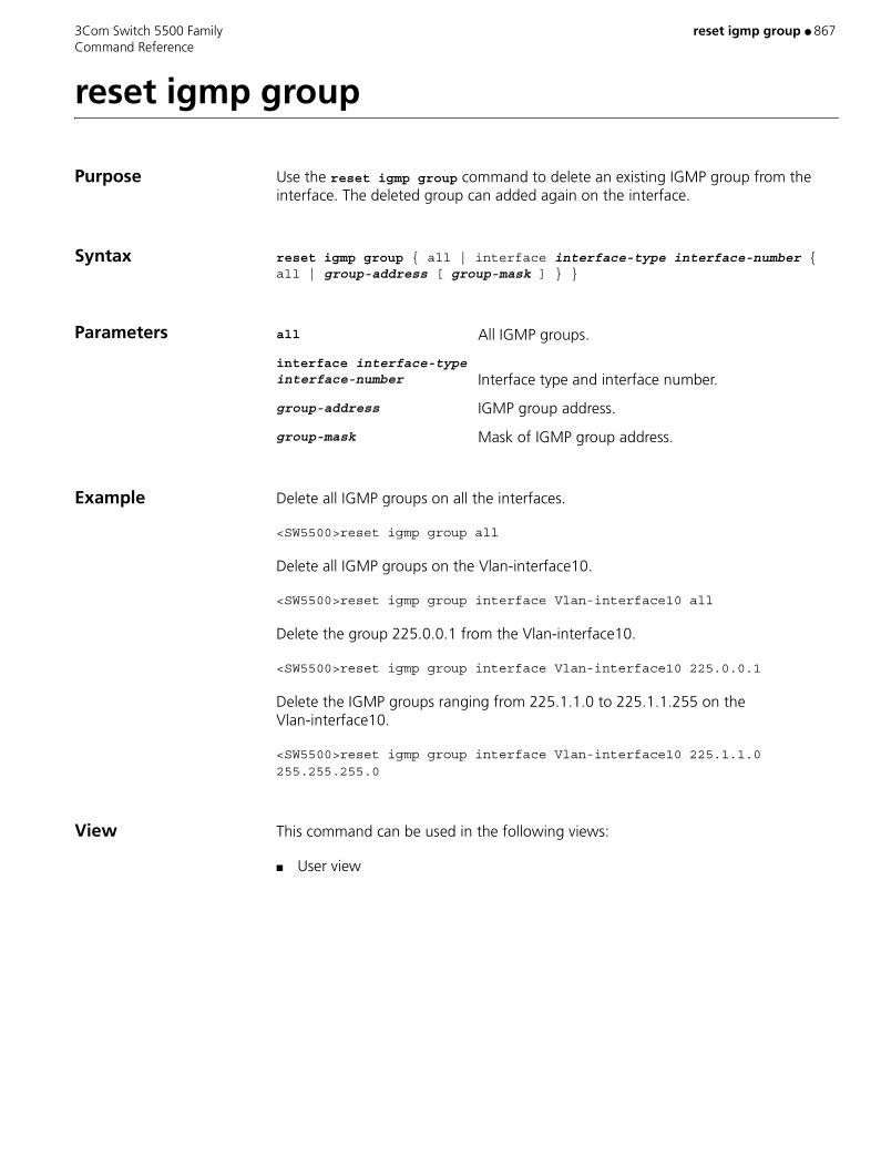
3Com Switch 5500 Family reset igmp group ● 867 Command Reference
reset igmp group
Purpose Use the reset igmp group command to delete an existing IGMP group from the interface. The deleted group can added again on the interface.
Syntax reset igmp group { all | interface interface-type interface-number { all | group-address [ group-mask ] } }
Parameters all All IGMP groups.
interface interface-type interface-number Interface type and interface number.
group-address IGMP group address.
group-mask Mask of IGMP group address.
Example Delete all IGMP groups on all the interfaces.
<SW5500>reset igmp group all
Delete all IGMP groups on the Vlan-interface10.
<SW5500>reset igmp group interface Vlan-interface10 all
Delete the group 225.0.0.1 from the Vlan-interface10.
<SW5500>reset igmp group interface Vlan-interface10 225.0.0.1
Delete the IGMP groups ranging from 225.1.1.0 to 225.1.1.255 on the Vlan-interface10.
<SW5500>reset igmp group interface Vlan-interface10 225.1.1.0 255.255.255.0
View This command can be used in the following views:
■ User view
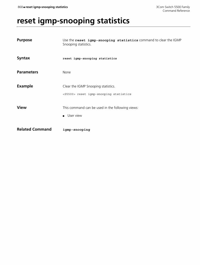
868 ● reset igmp-snooping statistics 3Com Switch 5500 Family Command Reference
reset igmp-snooping statistics
Purpose Use the reset igmp-snooping statistics command to clear the IGMP Snooping statistics.
Syntax reset igmp-snooping statistics
Parameters None
Example Clear the IGMP Snooping statistics.
<S5500> reset igmp-snooping statistics
View This command can be used in the following views:
■ User view
Related Command igmp-snooping

3Com Switch 5500 Family reset ip statistics ● 869 Command Reference
reset ip statistics
Purpose Use the reset ip statistics command to clear the IP statistics information.
Syntax reset ip statistics
Parameters None
Example To clear the IP statistics information, enter the following:
<SW5500>reset ip statistics
View This command can be used in the following views:
■ User view
Related Commands ■ display ip interface vlan-interface
■ display ip statistics
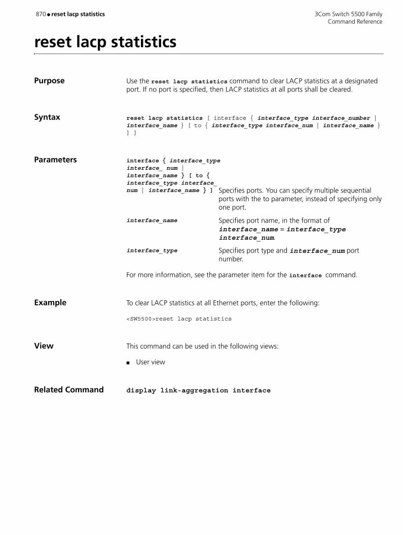
870 ● reset lacp statistics 3Com Switch 5500 Family Command Reference
reset lacp statistics
Purpose Use the reset lacp statistics command to clear LACP statistics at a designated port. If no port is specified, then LACP statistics at all ports shall be cleared.
Syntax reset lacp statistics [ interface { interface_type interface_number | interface_name } [ to { interface_type interface_num | interface_name } ] ]
Parameters interface { interface_type interface_ num | interface_name } [ to { interface_type interface_ num | interface_name } ] Specifies ports. You can specify multiple sequential
ports with the to parameter, instead of specifying only one port.
interface_name Specifies port name, in the format of interface_name = interface_type interface_num.
interface_type Specifies port type and interface_num port number.
For more information, see the parameter item for the interface command.
Example To clear LACP statistics at all Ethernet ports, enter the following:
<SW5500>reset lacp statistics
View This command can be used in the following views:
■ User view
Related Command display link-aggregation interface
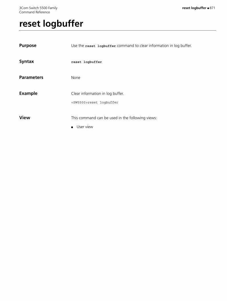
3Com Switch 5500 Family reset logbuffer ● 871 Command Reference
reset logbuffer
Purpose Use the reset logbuffer command to clear information in log buffer.
Syntax reset logbuffer
Parameters None
Example Clear information in log buffer.
<SW5500>reset logbuffer
View This command can be used in the following views:
■ User view
872 ● reset msdp peer 3Com Switch 5500 Family Command Reference
reset msdp peer
Purpose Use the reset msdp peer command to reset the TCP connection with the specified MSDP peer and clear all statistics information of that MSDP peer.
Syntax reset msdp peer peer-address
Parameters peer-address IP address of the MSDP peer, in the dotted decimal format
Example Reset the TCP connection with the MSDP peer 125.10.7.6 and the statistics of the MSDP peer.
<S5500> reset msdp peer 125.10.7.6
View This command can be used in the following views:
■ User view
Related Command peer

3Com Switch 5500 Family reset msdp sa-cache ● 873 Command Reference
reset msdp sa-cache
Purpose Use the reset msdp sa-cache command to clear cached SA entries of the MSDP peer.
Syntax reset msdp sa-cache [ group-address ]
Parameters group-address Group address; the cached (S, G) entries matching this address are to be deleted from the SA cache. If no multicast group address is specified, all cached SA entries will be cleared.
Example Clear the cached entries whose group address is 225.5.4.3 from the SA cache.
<S5500> reset msdp sa-cache 225.5.4.3
View This command can be used in the following views:
■ User view
Related Commands ■ cache-sa-enable
■ display msdp sa-cache
874 ● reset msdp statistics 3Com Switch 5500 Family Command Reference
reset msdp statistics
Purpose Use the reset msdp statistics command to clear the statistics information of one or more MSDP peers without resetting the MSDP peer(s).
Syntax reset msdp statistics [ peer-address ]
Parameters peer-address Address of the MSDP peer whose statistics, reset information and input/output information will be cleared. If no MSDP peer address is specified, the statistics information of all MSDP peers will be cleared.
Example Clear the statistics information of the MSDP peer 125.10.7.6.
<S5500> reset msdp statistics 125.10.7.6
View This command can be used in the following views:
■ User view
3Com Switch 5500 Family reset multicast forwarding-table ● 875 Command Reference
reset multicast forwarding-table
Purpose Use the reset multicast forwarding-table command to clear MFC forwarding entries or statistic information of MFC forwarding entries.
Syntax reset multicast forwarding-table [ statistics ] { all | { group-address [ mask { group-mask | group-mask-length } ] | source-address [ mask { source-mask | source-mask-length } ] | incoming-interface interface-type interface-number } * }
Parameters statistics If it is selected, the system clears the statistic information of MFC forward entries. Otherwise, the system clears MFC forward entries.
all All MFC forward entries.
group-address Specifies group address.
group-mask Specifies Mask of group address
group-mask-length Specifies mask length of group address.
source-address Specifies source address.
source-mask Specifies mask of source address.
source-mask-length Specifies mask length of source address.
incoming-interface Specifies incoming interface for the forward entry.
interface-type interface-number Interface type and interface number.
Example Clear the forwarding entry with address of 225.5.4.3 from the MFC forwarding table.
<SW5500>reset multicast forwarding-table 225.5.4.3
Clear statistic information of the forwarding entry with address of 225.5.4.3 from the MFC forwarding table.
<SW5500>reset multicast forwarding-table statistics 225.5.4.3
View This command can be used in the following views:
■ User view
Description Type in the source address first and group address after in the command, ensuring that both addresses are valid. The system prompts error information if invalid addresses are entered.

876 ● reset multicast forwarding-table 3Com Switch 5500 Family Command Reference
Related Command ■ display multicast forwarding-table
■ reset pim routing-table
■ reset multicast routing-table

3Com Switch 5500 Family reset multicast routing-table ● 877 Command Reference
reset multicast routing-table
Purpose Use the reset multicast routing-table command to clear route entries from the core multicast routing table, as well as MFC forwarding entries.
Syntax reset multicast routing-table { all | { group-address [ mask { group-mask | group-mask-length } ] | source-address [ mask { source-mask | source-mask-length } ] | { incoming-interface interface-type interface-number } } * }
Parameters all All route entries in the core multicast routing table.
group-address Specifies group address.
group-mask Specifies Mask of group address.
group-mask-length Specifies mask length of group address.
source-address Specifies source address.
source-mask Specifies mask of source address.
source-mask-length Specifies mask length of source address.
incoming-interface Specifies incoming interface for the forward entry.
interface-type interface-number Interface type and interface number.
Example Clear the route entry with address of 225.5.4.3 from the core multicast routing table.
<SW5500>reset multicast routing-table 225.5.4.3
Clear statistic information of the forward entry with address of 225.5.4.3 from the MFC forwarding table.
<SW5500>reset multicast forwarding-table statistics 225.5.4.3
View This command can be used in the following views:
■ User view
Description Type in the source address first and group address after in the command, ensure that both addresses are valid. The system prompts error information if invalid addresses are entered.
Related Commands ■ display multicast forwarding-table
■ reset pim routing-table
■ reset multicast forwarding-table

878 ● reset ndp statistics 3Com Switch 5500 Family Command Reference
reset ndp statistics
Purpose Use the reset ndp statistics command to reset the NDP counters to clear the NDP statistics.
Syntax reset ndp statistics [ interface port-list ]
Parameters port-list Specifies a list of ports connected with the specified port. A list may contain consecutive or separated ports, or the combination of consecutive and separated ports. The argument is expressed as { interface-type interface-number | interface-name } [ to { interface-type interface-number | interface-name } ] } &<1-10>. interface-type specifies the port type. interface-number specifies the port number, expressed as slot number/port number. Key word to helps specify a port range.
Example Clear NDP statistics.
<S5500> reset ndp statistics
View This command can be used in the following views:
■ User view
3Com Switch 5500 Family reset ospf all ● 879 Command Reference
reset ospf all
Purpose Using the reset ospf all command, you can reset the OSPF process, as follows:
■ Invalid LSAs are cleared immediately without waiting for LSA timeout.
■ If the Router ID changes, a new Router ID takes effect to execute the command.
■ Re-elect DR and BDR.
■ OSPF configuration before the restart will not be lost.
Syntax reset ospf [ statistics ] { all | process-id }
Parameters all Resets all OSPF processes.
process-id The process ID of OSPF. Valid values are 1 to 65535. If not specified, the default process ID is 1.
statistics Enter to reset OSPF statistics.
Example Reset all the OSPF processes:
<SW5500>reset ospf all
View This command can be used in the following views:
■ User view
Description After you enter the command, you are asked to confirm that the OSPF protocol should be re-enabled.

880 ● reset password-control blacklist 3Com Switch 5500 Family Command Reference
reset password-control blacklist
Purpose Use the reset password-control blacklist command to delete all the user entries in the blacklist.
Use the reset password-control blacklist username username command to delete specified user entries in the blacklist.
Syntax reset password-control blacklist [ username username ]
Parameters username username Specifies a user name.
Example Check the user information in the blacklist; as you can see, the blacklist contains three users: test, tes, and test2.
S5500<S5500> display password-control blacklist
USERNAME IP
test 192.168.30.25
tes 192.168.30.24
test2 192.168.30.23
Delete the user test from the blacklist.
S5500<S5500> reset password-control blacklist user-name test Are you sure to delete the blacklist-users ?[Y/N]y All the blacklist users have been cleared.
Check the current user information in the blacklist; as you can see, the user test has been deleted.
<S5500]> display password-control blacklistUSERNAME IPtes 192.168.30.24test2 192.168.30.23
View This command can be used in the following views:
■ User view
3Com Switch 5500 Family reset password-control history-record ● 881 Command Reference
reset password-control history-record
Purpose Use the reset password-control history-record command to delete the history password records of all users.
Use the reset password-control history-record username username command to delete the history password record of a specific user.
Syntax reset password-control history-record [ username username ]
Parameters username Name of the user whose history password record will be deleted.
Example Delete the history password records of all users
S5500<S5500> reset password-control history-record Are you sure to delete all the history record?[Y/N]
If you input "Y", the system deletes all the history password records of all users and gives the following prompt:
All historical passwords have been cleared for all users.
Delete the history password records of the user test.
S5500<S5500> reset password-control history-record username testAre you sure to delete all the history record of user test ?[Y/N]
If you input "Y", the system deletes all the history password records of the specified user and gives the following prompt:
All historical passwords have been cleared for user test.
View This command can be used in the following views:
■ User view

882 ● reset password-control history-record super 3Com Switch 5500 Family Command Reference
reset password-control history-record super
Purpose Use the reset password-control history-record super level command to delete the history records of the super password for the users at the specified level.
Use the reset password-control history-record super command to delete the history records of all super passwords.
Syntax reset password-control history-record super [ level level-value ]
Parameters level-value Privilege level, the history records of the super password for the users at this level will be deleted. Valid values are 1 to 3.
Example Delete the history records of the super password for the users at level 2.
S5500<S5500> reset password-control history-record super level 2Are you sure to clear the specified-level super password history records?[Y/N]
If you input "Y", the system deletes the history records of the super password for the users at level 2.
View This command can be used in the following views:
■ User view

3Com Switch 5500 Family reset pim neighbor ● 883 Command Reference
reset pim neighbor
Purpose Use the reset pim neighbor command to clear a PIM neighbor
Syntax reset pim neighbor { all | { neighbor-address | interface interface-type interface-number} * }
Parameters all All PIM neighbors.
neighbor-address Specifies neighbor address.
interface interface-type interface-number Specifies interface.
Example Clear the PIM neighbor 25.5.4.3.
<SW5500>reset pim neighbor 25.5.4.3
View This command can be used in the following views:
■ User view
Related Command display pim neighbor

884 ● reset pim routing-table 3Com Switch 5500 Family Command Reference
reset pim routing-table
Purpose Use the reset pim routing-table command to clear a PIM route entry.
Syntax reset pim routing-table { all | { group-address [ mask { group-mask | group-mask-length }] | source-address [ mask { source-mask | source-mask-length }] | { incoming-interface { interface-type interface-number | null } } } * }
Parameters all All PIM neighbors.
group-address Specifies group address.
mask group-mask Specifies group mask.
mask-length group-mask-length Specifies mask length of the group address.
source-address Specifies source address.
mask source-mask Specifies source mask.
mask-length source-mask-length Specifies mask length of the group address.
incoming-interface Specifies incoming interface for the route entry in PIM routing table.
interface-type interface-number Specifies the interface.
null Specifies the incoming interface of the route entry as null.
Example Clear the route entries with group address 225.5.4.3 from the PIM routing table.
<SW5500>reset pim routing-table 225.5.4.3
View This command can be used in the following views:
■ User view
Description You can type in source-address first and group-address after in the command, as long as they are valid. Error information will be given if you type in invalid addresses.
If in this command, the group-address is 224.0.0.0/24 and source-address is the RP address (where group address can have a mask, but the resulted IP address must be 224.0.0.0, and source address has no mask), then it means only the (*, *, RP) item will be cleared.
If in this command, the group-address is any a group address, and source-address is 0 (where group address can have a mask, and source address has no mask), then only the (*, G) item will be cleared.

3Com Switch 5500 Family reset pim routing-table ● 885 Command Reference
This command clears multicast route entries from PIM routing table, as well as the corresponding route entries and forward entries in the multicast core routing table and MFC.
Related Commands ■ display pim routing-table
■ reset multicast routing-table
■ reset multicast forwarding-table

886 ● reset radius statistics 3Com Switch 5500 Family Command Reference
reset radius statistics
Purpose Use the reset radius statistics command to clear the statistic information related to the RADIUS protocol.
Syntax reset radius statistics
Parameters None
Example To clear the RADIUS protocol statistics, enter the following:
<SW5500>reset radius statistics
View This command can be used in the following views:
■ User view
Related Command display radius

3Com Switch 5500 Family reset recycle-bin ● 887 Command Reference
reset recycle-bin
Purpose Use the reset recycle-bin command to completely delete file(s) in the recycle bin.
Syntax reset recycle-bin [ file-url ] [ /force ]
reset recycle-bin [ /fabric ]
Parameters file-url Path name or file name of the file in the flash memory, consisting of a character string from 1 to 142 characters long. This argument supports the wildcard “*”.
/force Gives no prompt for the delete operation.
/fabric Operates on the whole fabric.
Example Clear recycle bin on all units in the fabric.
<S5500> reset recycle-bin /fabricSqueeze the recycle bins in fabric ? [Y/N]:y Unit1 reset success! Unit2 reset success!%Apr 4 11:42:57:160 2000 S5500 VFS/6/OPLOG:- 1 - Unit1 reset success!%Apr 4 11:42:57:236 2000 S5500 VFS/6/OPLOG:- 1 - Unit2 reset success!
View This command can be used in the following views:
■ User view
Description The files that are deleted using the delete command are still stored in the recycle bin. To delete them completely, you can use the reset recycle-bin command.
When you execute the reset recycle-bin /fabric command, the system does not prompt you to give a confirmation for each file you want to delete.

888 ● reset saved-configuration 3Com Switch 5500 Family Command Reference
reset saved-configuration
Purpose Use the reset saved-configuration command to delete the main or backup configuration files on the Ethernet switches in the fabric.
Syntax reset saved-configuration [ backup | main ]
Parameters main Main configuration file.
backup Backup configuration file.
Example Delete the main configuration file to be used for next startup.
<S5500>reset saved-configuration mainThe saved configuration will be erased. Are you sure?[Y/N]y Configuration in flash is being cleared. Please wait ... ... Configuration in flash is cleared.
View This command can be used in the following views:
■ User view
Description Executing the reset saved-configuration command with neither backup nor main keyword will delete the main configuration files in the fabric.
Generally, the reset saved-configuration command is used in the following cases:
■ After the software on an Ethernet switch is updated, the configuration files in the flash memory are not compatible with the new software version. In this case, you can use the command to delete the old configuration files.
■ It is expected to apply an Ethernet switch that has ever been used to a new environment, but the old configuration files cannot adapt to the new environment. In this case, you can use the command to delete the old configuration files and then reconfigure the Ethernet switch.
CAUTION:
■ Use the reset saved-configuration command with caution. You are recommended to use this command under the guidance of technical support personnel.
■ When the Ethernet switch is powered on and initialized, if no configuration file is found in the flash memory, the default parameters are used for the initialization.
■ If the file to be deleted does not exist, the system will report error message.

3Com Switch 5500 Family reset saved-configuration ● 889 Command Reference
Related Command save
890 ● reset stop-accounting-buffer 3Com Switch 5500 Family Command Reference
reset stop-accounting-buffer
Purpose Use the reset stop-accounting-buffer command to clear the stop-accounting requests that have no response and are buffered on the switch.
Syntax reset stop-accounting-buffer hwtacacs-scheme hwtacacs-scheme-name
Parameters hwtacacs-scheme hwtacacs-scheme-name
Configures to delete the stop-accounting requests from the buffer according to the specified HWTACACS scheme name. The hwtacacs-scheme-name specifies the HWTACACS scheme name with a character string not exceeding 32 characters, excluding“?”.
Example Delete the buffered stop-accounting requests that are related to the HWTACACS scheme “3Com”.
<S5500> reset stop-accounting-buffer hwtacacs-scheme 3Com
View This command can be used in the following views:
■ User view
Related Commands ■ display stop-accounting buffer
■ retry stop-accounting
■ stop-accounting-buffer enable

3Com Switch 5500 Family reset stp ● 891 Command Reference
reset stp
Purpose Use the reset stp command to clear the STP statistics of specified Ethernet ports.
Syntax reset stp [ interface interface-list ]
Parameters interface-list List of Ethernet ports. You can specify multiple Ethernet ports by providing this argument in the form of interface-list = { interface-type interface-number [ to interface-type interface-number ] } &<1-10>, where &<1-10> means that you can provide up to 10 port indexes/port index lists for this argument.
Example Clear the STP statistics of ports Ethernet1/0/1 through Ethernet1/0/3.
<S5500> reset stp interface Ethernet 1/0/1 to Ethernet 1/0/3
View This command can be used in the following views:
■ User view
Description Statistics about spanning trees includes the number of the TCN BPDUs, Configuration BPDUs, RST BPDUs, and MST BPDUs sent and received through a port or specific ports. Note that statistics about STP BPDUs and TCN BPDUs are collected only for the CIST..
This command clears the STP statistics about the specified ports if you specify the interface-list argument. If you do not specify the interface-list argument, this command clears the STP statistics about all ports.
Related Command display stp

892 ● reset tcp statistics 3Com Switch 5500 Family Command Reference
reset tcp statistics
Purpose Use the reset tcp statistics command to clear the TCP statistics information.
Syntax reset tcp statistics
Parameters None
Example To clear the TCP statistics information, enter the following:
<SW5500>reset tcp statistics
View This command can be used in the following views:
■ User view
Related Command display tcp statistics

3Com Switch 5500 Family reset traffic-statistic ● 893 Command Reference
reset traffic-statistic
Purpose Use the reset traffic-statistic command to reset the traffic statistics information.
Syntax reset traffic-statistic inbound { user-group acl-number [ rule rule ] | ip-group acl-number [ rule rule ] | link-group acl-number [ rule rule ] }
Parameters inbound Specifies the traffic received by the Ethernet port.
user-group acl-number Activates user-defined ACLs. acl-number: Sequence number of ACL, ranging from 5000 to 5999.
ip-group acl-number Activates IP ACLs, including basic and advanced ACLs. acl-number: Sequence number of ACL, ranging from 2000 to 3999.
link-group acl-number Activates Layer 2 ACLs. acl-number: Sequence number of ACL, ranging from 4000 to 4999.
rule rule Specifies the sub-item of an active ACL, ranging from 0 to 65534; if not specified, all sub-items of the ACL will be activated. If only an IP ACL or a Layer 2 ACL is activated, this parameter can be omitted. If both IP and Layer 2 ACLs are activated at the same time, the rule parameter cannot be omitted.
Example Clear the statistics information about ACL 2000.
<SW5500>system-viewSystem View: return to User View with Ctrl+Z[SW5500]interface Ethernet 1/0/1[SW5500-Ethernet1/0/1]reset traffic-statistic inbound ip-group 2000[SW5500-Ethernet1/0/1]
View This command can be used in the following views:
■ Ethernet Port view
Description This command is used for clearing the statistics information about all the traffic or a specified one.
Table 98 Comparison of Statistics Information reset commands
Command Function
reset acl counter Reset the statistics information of the ACL which is used in the case of filtering or classifying the data treated by the software of the Switch. The case includes: ACL cited by route policy function and ACL used for control logon user.

894 ● reset traffic-statistic 3Com Switch 5500 Family Command Reference
reset traffic-statistic
Reset statistic information of traffic. This command is used in the case of filtering or classifying the data transmitted by the hardware of the Switch. Commonly, this command is used to reset the statistics information of the traffic-statistic command.
Table 98 Comparison of Statistics Information reset commands (continued)
Command Function

3Com Switch 5500 Family reset trapbuffer ● 895 Command Reference
reset trapbuffer
Purpose Use the reset trapbuffer command to clear information in trap buffer.
Syntax reset trapbuffer
Parameters None
Example Clear information in trap buffer.
<SW5500>reset trapbuffer
View This command can be used in the following views:
■ User view
896 ● reset udp statistics 3Com Switch 5500 Family Command Reference
reset udp statistics
Purpose Use the reset udp statistics command to clear the UDP statistics information.
Syntax reset udp statistics
Parameters None
Example To clear the UDP traffic statistics information, enter the following:
<SW5500>reset udp statistics
View This command can be used in the following views:
■ User view
3Com Switch 5500 Family reset vrrp statistics ● 897 Command Reference
reset vrrp statistics
Purpose Use the reset vrrp command to clear the statistics information about VRRP.
Syntax reset vrrp statistics [ vlan-interface vlan-id ] [ virtual-router-ID ]
Parameters statistics Displays VRRP statistics.
vlan-interface vlan-id Specifies a VLAN interface ID.
virtual-router-ID VRRP virtual router ID. Valid values are 1 to 255.
Example Clear the VRRP statistics on the switch.
<S5500> reset vrrp statistics
View This command can be used in the following views:
■ User view
Description When you execute this command,
■ If the interface index and backup group ID are not specified, the statistics information about all the backup groups on the switch is cleared.
■ If only the interface index is specified, the statistics information about all the backup groups on the interface will be cleared.
■ If both the interface index and backup group ID are specified, the statistics information about the specified backup group on the interface is cleared.
The VRRP feature is supported by Switch 5500-EI series switches but is not supported by Switch 5500-SI series switches.
898 ● resilient-arp enable 3Com Switch 5500 Family Command Reference
resilient-arp enable
Purpose Use the resilient-arp enable command to enable the resilient ARP function.
Use the undo resilient-arp enable command to disable the resilient ARP function.
Syntax resilient-arp enable
undo resilient-arp enable
Parameters None
Default By default, resilient ARP function is enabled.
Example To enable the resilient ARP function, enter the following:
<SW5500>system-viewSystem View: return to User View with Ctrl+Z.[SW5500]resilient-arp enable
View This command can be used in the following views:
■ System view
Related Command display resilient-arp

3Com Switch 5500 Family resilient-arp interface vlan-interface ● 899 Command Reference
resilient-arp interface vlan-interface
Purpose Use the resilient-arp interface vlan-interface command to configure the Switch to send resilient ARP packets out the specified VLAN interface.
Use the undo resilient-arp interface vlan-interface command to stop the Switch from sending ARP packets out of the specified VLAN interface.
Syntax resilient-arp interface vlan-interface vlan_id
undo resilient-arp interface vlan-interface vlan_id
Parameters vlan_id Enter the VLAN interface ID. If no interface ID is specified, the system sends resilient ARP packets out of VLAN interface 1.
Example To set VLAN interface 2 to send resilient ARP packets., enter the following:
<SW5500>system-viewSystem View: return to User View with Ctrl+Z.[SW5500]resilient-arp interface vlan-interface 2
View This command can be used in the following views:
■ System view
Related Command display resilient-arp

900 ● restore startup-configuration from 3Com Switch 5500 Family Command Reference
restore startup-configuration from
Purpose Use the restore startup-configuration from command to download or restore the startup configuration of either a specified switch from a file on a TFTP server or the whole fabric.
Syntax restore { unit unit-id | fabric } startup-configuration from source-addr filename.cfg
Parameters unit-id Unit ID of a switch.
fabric Specifies the whole fabric system.
source-addr Host name or IP address of an TFTP server.
filename.cfg Name of the configuration file to be downloaded. This file name is suffixed with cfg.
Example Restore the backupstartup configuration of unit 7 from the file u2aaa.cfg from on the TFTP server with the IP address 1.1.1.253.
<S5500> restore unit 7 startup-configuration from 1.1.1.253 aaa.cfg Restore startup configuration from 1.1.1.253. Please wait... File will be transferred in binary mode. Downloading file from remote tftp server, please wait........ TFTP: 20291958 bytes receivedsent in 0 second(s). File downloaded successfully.
Unit 27: Restore startup current configuration finished! Unit 27: Restore startup current configuration finished!
Restore the startup configuration of the whole fabric from the file bbb.cfg on the TFTP server with the IP address 1.1.1.253.
<S5500> restore fabric startup-configuration from 1.1.1.253 bbb.cfgRestore startup configuration from 1.1.1.253. Please wait... File will be transferred in binary mode. Downloading file from remote tftp server, please wait... TFTP: 2029 bytes sent in 0 second(s).
File downloaded successfully.
Unit 7: Restore startup current configuration finished! Unit 8: Restore startup current configuration finished!
View This command can be used in the following views:
■ User view

3Com Switch 5500 Family retry ● 901 Command Reference
retry
Purpose Use the retry command to set the maximum retry times during a detect operation.
Syntax retry retry-times
Parameters retry-times Retry times during a detect operation. Valid values are 0 to 10. If not specified, the default is 2.
Example Specify the maximum number of retires to 3 for detecting group 10.
<S5500> system-viewSystem View: return to User View with Ctrl+Z.[S5500] detect-group 10[S5500-detect-group-10] retry 3
View This command can be used in the following views:
■ Detecting Group view

902 ● retry realtime-accounting 3Com Switch 5500 Family Command Reference
retry realtime-accounting
Purpose Use the retry realtime-accounting command to configure the maximum number of retries for real-time accounting requests.
Use the undo retry realtime-accounting command to restore the maximum number of retries for real-time accounting requests to the default value.
Syntax retry realtime-accounting retry-times
undo retry realtime-accounting
Parameters retry-times Specifies the maximum times of real-time accounting request failing to be responded. Valid values are 1 to 255. If not specified, the accounting request can fail to be responded up to 5 times.
Example To allow the real-time accounting request failing to be responded for up to 10 times, enter the following:
<SW5500> system-viewSystem View: return to User View with Ctrl+Z.[SW5500]radius scheme 3Com[SW5500-radius-3Com]retry realtime-accounting 10
View This command can be used in the following views:
■ RADIUS Scheme view
Description RADIUS server usually checks if a user is online with timeout timer. If the RADIUS server has not received the real-time accounting packet from NAS, it will consider that there is line or device failure and stop accounting. Therefore, it is necessary to disconnect the user at the NAS end and on the RADIUS server synchronously when unexpected failure occurs. The Switch 5500 Series supports a maximum number of times that real-time accounting requests can fail to be responded to. NAS will disconnect the user if it has not received a real-time accounting response from the RADIUS server for the number of specified times.
How is the value of count calculated? Suppose RADIUS server connection will timeout in T and the real-time accounting interval of NAS is t, then the integer part of the result from dividing T by t is the value of count. Therefore, when applied, T is suggested the numbers which can be divided exactly by t.
Related Command radius-scheme
3Com Switch 5500 Family retry stop-accounting ● 903 Command Reference
retry stop-accounting
Purpose Use the retry stop-accounting command to configure the maximal retransmission times after stopping accounting request.
Use the undo retry stop-accounting command to restore the retransmission times to the default value.
Syntax retry stop-accounting retry-times
undo retry stop-accounting
Parameters retry-times Specifies the maximal retransmission times after stopping accounting request. Valid values are 10 to 65535. If not specified, the default value is 500.
Example To indicate that, when stopping accounting request for the server “3Com” in the RADIUS server group, the Switch will retransmit the packets for up to 1000 times, enter the following:
<SW5500>system-viewSystem View: return to User View with Ctrl+Z.[SW5500]radius scheme 3Com[SW5500-radius-3Com]retry stop-accounting 1000
View This command can be used in the following views:
■ RADIUS Scheme view
Description Because the stopping accounting request concerns account balance and will affect the amount of charge, which is very important for both the user and ISP, NAS shall make its best effort to send the message to RADIUS accounting server. Accordingly, if the message from the Switch to RADIUS accounting server has not been responded, the Switch shall save it in the local buffer and retransmit it until the server responds or discard the messages after transmitting for specified times.
Related Commands ■ display stop-accounting buffer
■ radius-scheme
■ reset stop-accounting-buffer
904 ● return 3Com Switch 5500 Family Command Reference
return
Purpose Use the return command to return to user view from any other view.
Syntax return
Parameters None
Example To return to user view from any other view (the example below shows the command entered from the system view), enter the following.
<SW5500>system-viewSystem View: return to User View with Ctrl+Z.[SW5500]return<SW5500>
Description Performs the same function as Ctrl+Z.
To return to the next highest level of view, use quit.
View This command can be used in the following views:
■ System view or higher
3Com Switch 5500 Family revision-level ● 905 Command Reference
revision-level
Purpose Use the revision-level command to set the MSTP revision level for a switch.
Use the undo revision-level command to restore the default revision level.
Syntax revision-level level
undo revision-level
Parameters level MSTP revision level for the switch. Valid values are 0 to 65535. If not specified, the default is 0.
Example Set the MSTP revision level of the MST region where the switch resides to 5.
<S5500> system-view System View: return to User View with Ctrl+Z.[S5500] stp region-configuration [S5500-mst-region] revision-level 5
View This command can be used in the following views:
■ MST Region view
Description MSTP revision level, along with MST region name and VLAN mapping table, determines the MST region to which a switch belongs.
Related Commands ■ active region-configuration
■ check region-configuration
■ instance
■ region-name
■ vlan-mapping modulo

906 ● rip 3Com Switch 5500 Family Command Reference
rip
Purpose Use the rip command to enable RIP and enter the RIP command view.
Use the undo rip command to disable RIP.
Syntax rip
undo rip
Parameters None
Default By default, RIP is disabled.
Example To enable RIP, and enter RIP view, enter the following:
<SW5500>system-viewSystem View: return to User View with Ctrl+Z.[SW5500]rip[SW5500-rip]
View This command can be used in the following views:
■ System view
Description Enabling RIP does not affect interface configurations.
3Com Switch 5500 Family rip authentication-mode ● 907 Command Reference
rip authentication-mode
Purpose Use the rip authentication-mode command to configure the RIP-2 authentication mode and its parameters for the Switch 5500.
Use the rip authentication-mode simple command to configure the RIP-2 simple text authentication key.
Use the rip authentication-mode md5 usual key-string to configure the MD5 cipher text authentication key for RIP-2.
Use the rip authentication-mode md5 nonstandard key-string key-id command to configure the MD5 cipher text authentication ID for RIP-2.
Use the undo rip authentication-mode command to cancel RIP-2 authentication.
Syntax rip authentication-mode { simple password | md5 { usual key-string | nonstandard key-string key-id }}
undo rip authentication-mode
Parameters simple Specifies simple text authentication mode.
password Specifies the simple text authentication key.
md5 Specifies MD5 cipher text authentication mode.
usual Specifies the MD5 cipher text authentication packet to use the general packet format (RFC1723 standard format).
key-string Specifies the MD5 cipher text authentication key. If it is entered in plain text, the MD5 key is a character string not exceeding 16 characters. This key is displayed in a cipher text form in a length of 24 characters when display current-configuration command is executed. Inputting the MD5 key in cipher text form with 24 characters long is also supported.
nonstandard Sets the MD5 cipher text authentication packet to use a nonstandard packet format (as described in RFC2082).
key-id Specifies an MD5 cipher text authentication identifier, ranging from 1 to 255.
Example To specify the interface “Vlan-interface 1” to use simple authentication with the key set to “aaa”, enter the following:
<SW5500>system-viewSystem View: return to User View with Ctrl+Z.[SW5500]interface Vlan-interface 1[SW5500-Vlan-interface1]rip version 2[SW5500-Vlan-interface1]rip authentication-mode simple aaa

908 ● rip authentication-mode 3Com Switch 5500 Family Command Reference
To specify the interface Vlan-interface 1 to use MD5 authentication with the key string as “aaa” and the packet type set to usual, enter the following:
[SW5500]interface Vlan-interface 1[SW5500-Vlan-interface1]rip version 2[SW5500-Vlan-interface1]rip authentication-mode md5 key-string aaa[SW5500-Vlan-interface1]rip authentication-mode md5 type nonstandard
To set MD5 authentication on Vlan-interface 1 with the key string set to “aaa” and the packet type set to usual, enter the following:
[SW5500]interface Vlan-interface 1[SW5500-Vlan-interface1]rip version 2[SW5500-Vlan-interface1]rip authentication-mode md5 usual aaa
View This command can be used in the following views:
■ Interface view
Description There are two RIP-2 authentication modes: simple authentication and MD5 cipher text authentication. When you use MD5 cipher text authentication mode, two types of packet formats are available. The standard format (set using the usual parameter), is described in RFC 1723. The non-standard format (set using the nonstandard parameter), is described in RFC 2082.
RIP-1 does not support authentication.
Related Command rip version
3Com Switch 5500 Family rip input ● 909 Command Reference
rip input
Purpose Use the rip input command to allow an interface to receive RIP packets.
Use the undo rip input command to block an interface from receiving RIP packets.
Syntax rip input
undo rip input
Parameters None
Default By default, all interfaces except loopback interfaces are able to receive RIP packets.
Example To set the interface Vlan-interface 1 not to receive RIP packets, enter the following:
<SW5500>system-viewSystem View: return to User View with Ctrl+Z.[SW5500]interface Vlan-interface 1[SW5500-Vlan-interface1]undo rip input
View This command can be used in the following views:
■ Interface view
Description This command is used in conjunction with two other two commands: rip output and rip work. The rip input and rip output commands control, respectively, the receipt and the transmission of RIP packets on an interface. The rip work command allows both receipt and transmission of RIP packets.
Related Commands ■ rip output
■ rip work

910 ● rip metricin 3Com Switch 5500 Family Command Reference
rip metricin
Purpose Use the rip metricin command to configure an additional route metric to be added to the route when an interface receives RIP packets.
Use the undo rip metricin command to restore the default value of this additional route metric.
Syntax rip metricin value
undo rip metricin
Parameters value Specifies an additional route metric to be added when receiving a packet. Valid values are 0 to 16. If not specified, the default value is 0.
Example To set the additional route metric to 2 when the interface Vlan-interface 1 receives RIP packets, enter the following:
<SW5500>system-viewSystem View: return to User View with Ctrl+Z.[SW5500]interface Vlan-interface 1[SW5500-Vlan-interface1]rip metricin 2
View This command can be used in the following views:
■ Interface view
Related Command rip metricout
3Com Switch 5500 Family rip metricout ● 911 Command Reference
rip metricout
Purpose Use the rip metricout command to configure an additional route metric to be added to a route when an interface transmits RIP packets.
Use the undo rip metricout command to restore the default value of the additional route metric.
Syntax rip metricout value
undo rip metricout
Parameters value Specifies an additional route metric added when transmitting a packet. Valid values are 1 to 16. If not specified, the default is 1.
Example To set the additional route metric to 2 when the interface Vlan-interface 1 transmits RIP packets, enter the following:
<SW5500>system-viewSystem View: return to User View with Ctrl+Z.[SW5500]interface Vlan-interface 1[SW5500-Vlan-interface1]rip metricout 2
View This command can be used in the following views:
■ Interface view
Related Command rip metricin
912 ● rip output 3Com Switch 5500 Family Command Reference
rip output
Purpose Use the rip output command to allow an interface to transmit RIP packets.
Use the undo rip output command to disable an interface from transmitting RIP packets.
Syntax rip output
undo rip output
Parameters None
Default By default, all interfaces except loopback interfaces are able to transmit RIP packets.
Example To prevent the interface Vlan-interface 1 from transmitting RIP packets, enter the following:
<SW5500>system-viewSystem View: return to User View with Ctrl+Z.[SW5500]interface Vlan-interface 1[SW5500-Vlan-interface1]undo rip output
View This command can be used in the following views:
■ Interface view
Description This command is used in conjunction with two other commands: rip input and rip work. rip input and rip output control, respectively, the receipt and the transmission of RIP packets on an interface. rip work allows both receipt and transmission of RIP packets.
Related Commands ■ rip input
■ rip work
3Com Switch 5500 Family rip split-horizon ● 913 Command Reference
rip split-horizon
Purpose Use the rip split-horizon command to configure an interface to use split horizon when transmitting RIP packets. This is the default.
Use the undo rip split-horizon command to configure an interface not to use split horizon when transmitting RIP packets.
Syntax rip split-horizon
undo rip split-horizon
Parameters None
Example To set the interface Vlan-interface 1 not to use split horizon when processing RIP packets, enter the following:
<SW5500>system-viewSystem View: return to User View with Ctrl+Z.[SW5500]interface Vlan-interface 1[SW5500-Vlan-interface1]undo rip split-horizon
View This command can be used in the following views:
■ Interface view
Description Normally, split horizon is necessary for preventing router loops. You may need to disable split horizon to ensure proper operation of protocols.

914 ● rip version 3Com Switch 5500 Family Command Reference
rip version
Purpose Use the rip version command to configure the version number of RIP packets on an interface.
Use the undo rip version command to restore the default RIP packet version on the interface. The interface RIP version is RIP-1.
Syntax rip version 1
rip version 2 [ broadcast | multicast ]
undo rip version
Parameters 1 Sets the interface version to RIP-1.
2 Sets the interface version to RIP-2.
broadcast Sets the transmission mode of an RIP-2 packet to broadcast.
multicast Sets the transmission mode of an RIP-2 packet to multicast.
Default By default, RIP-1 transmits packets in broadcast mode, while RIP-2 transmits packets in multicast mode.
Example To configure the interface Vlan-interface 1 to RIP-2 broadcast mode, enter the following:
<SW5500>system-viewSystem View: return to User View with Ctrl+Z.[SW5500]interface Vlan-interface 1[SW5500-Vlan-interface1]rip version 2 broadcast
View This command can be used in the following views:
■ Interface view
Description When running RIP-1, the interface receives and transmits RIP-1 packets, and can also receive RIP-2 broadcast packets.
When running RIP-2 in broadcast mode, the interface receives and transmits RIP-2 broadcast packets, and can also receive both RIP-1 packets and RIP-2 multicast packets.
When running RIP-2 in multicast mode, the interface receives and transmits RIP-2 multicast packets, and can also receive RIP-2 broadcast packets. The interface can not receive RIP-1 packets.
3Com Switch 5500 Family rip work ● 915 Command Reference
rip work
Purpose Use the rip work command to enable the RIP on an interface. This is the default.
Use the undo rip work command to disable RIP on an interface.
Syntax rip work
undo rip work
Parameters None
Example To disable the running of RIP on interface Vlan-interface 1, enter the following:
<SW5500>system-viewSystem View: return to User View with Ctrl+Z.[SW5500]interface Vlan-interface 1[SW5500-Vlan-interface1]undo rip work
View This command can be used in the following views:
■ Interface view
Description This command is used in conjunction with the rip input, rip output and network commands. Refer to the descriptions of these commands for details.
Related Commands ■ network
■ rip input
■ rip output
916 ● rmdir 3Com Switch 5500 Family Command Reference
rmdir
Purpose Use the rmdir command to delete the specified directory from the remote SFTP server.
Syntax rmdir remote-path
Parameters remote-path Name of a directory on the remote SFTP server.
Example Delete directory D:/temp1 from the remote SFTP server.
sftp-client> rmdir D:/temp1
View This command can be used in the following views:
■ SFTP Client view
3Com Switch 5500 Family rmon alarm ● 917 Command Reference
rmon alarm
Purpose Use the rmon alarm command to add an entry to the alarm table.
Use the undo rmon alarm command to delete an entry from this table.
Syntax rmon alarm entry-number alarm-variable sampling-time { delta | absolute } rising-threshold threshold-value1 event-entry1 falling-threshold threshold-value2 event-entry2 [ owner text ]
undo rmon alarm entry-number
Parameters entry-number Number of the entry to be added/deleted. Valid values are 1 to 65535.
alarm-variable Specifies the alarm variable with a character string, ranging from 1 to 256 characters, in the OID dotted format, like 1.3.6.1.2.1.2.1.10.1 (or ifInOctets.1).
sampling-time Specifies the sampling interval. Valid values are 5 to 65535 (measured in seconds).
delta Sampling type is delta.
absolute Sampling type is absolute.
rising-threshold threshold-value1 Rising threshold. Valid values are 0 to 2147483647.
event-entry1 Event number corresponding to the upper limit of threshold. Valid values are 0 to 65535.
falling-threshold threshold-value2 Falling threshold. Valid values are 0 to 2147483647.
event-entry2 Event number corresponding to the falling threshold. Valid values are 0 to 65535.
owner text Specifies the creator of the alarm. Length of the character string can be from 1 to 127 characters long.
Example Delete the information of entry 15 from the alarm table.
<SW5500>system-viewSystem View: return to User View with Ctrl+Z.[SW5500]undo rmon alarm 15[SW5500]
In this way, the alarm event can be triggered in the abnormal situations and then decides to log and send trap to the NM station.
View This command can be used in the following views:
■ System view

918 ● rmon event 3Com Switch 5500 Family Command Reference
rmon event
Purpose Use the rmon event command to add an entry to the event table.
Use the undo rmon event command to delete an entry from this table.
Syntax rmon event event-entry [ description string ] { log | trap trap-community | log-trap log-trapcommunity | none } [ owner rmon-station ]
undo rmon event event-entry
Parameters event-entry Number of the entry to be added/deleted. Valid values are 1 to 65535.
description string Event description. The length of the character string can be from 1 to 255 characters long.
log Log event.
trap Trap event.
trap-community The community of the Network Management station that the trap message is sent to.
log-trap Log and trap event.
log-trapcommunity The community of the Network Management station that the trap message is sent to.
none Neither log nor trap event.
owner rmon-station Name of the network management station that creates this entry. The length of the character string can be from 1 to 127 characters long.
Example Add the entry 10 to the event table and mark it as log event.
<SW5500>system-viewSystem View: return to User View with Ctrl+Z.[SW5500]rmon event 10 log[SW5500]
View This command can be used in the following views:
■ System view
Description Event management of RMON defines the way to deal with event number and event-log, send trap message or log while sending trap message. In this way, alarm events may obtain corresponding treatment
3Com Switch 5500 Family rmon history ● 919 Command Reference
rmon history
Purpose Use the rmon history command to add an entry to the history control table.
Use the undo rmon history command to delete an entry from history control table.
Syntax rmon history entry-number buckets number interval sampling-interval [ owner text-string ]
undo rmon history entry-number
Parameters entry-number Number of the entry to be added/deleted. Valid values are from 1 to 65535.
buckets number Capacity of the history table corresponding to the control line.
interval sampling-intervalSampling interval. Valid values are from 5 to 3600 (measured in seconds).
owner text-string Creator of the line. Length of the character string. Valid values are from 1 to127.
Example Delete the entry 15 from the history control table.
<SW5500>system-viewSystem View: return to User View with Ctrl+Z.[SW5500]interface Ethernet1/0/1[SW5500-Ethernet1/0/1]undo rmon history 15[SW5500-Ethernet1/0/1]
View This command can be used in the following views:
■ Ethernet Port view
Description Perform this command to sample, set sample parameter (sample time interval) and storage amounts for a port.�RMON will periodically perform data collection and save for query on this port.�Sample information includes utility, error number and total packet number.
920 ● rmon prialarm 3Com Switch 5500 Family Command Reference
rmon prialarm
Purpose Use the rmon prialarm command to add an entry to the extended RMON alarm table.
Use the undo rmon prialarm command to delete an entry from the extended RMON alarm table.
Syntax rmon prialarm entry-number alarm-var [ alarm-des ] sampling-timer { delta | absolute | changeratio } rising-threshold threshold-value1 event-entry1 falling-threshold threshold-value2 event-entry2 entrytype { forever | cycle cycle-period } [ owner text ]
undo rmon prialarm entry-number
Parameters entry-number Specifies the entry number. Valid values are from 1 to 65535.
alarm-var Specifies the alarm variable, which can be an arithmetic expression of several integer MIB node instances. The node can be OID in dotted notation.
alarm-des Specifies the alarm description with a length ranging from 0 to 127 characters.
sampling-timer Sets the sampling interval (in seconds). Valid values are 10 to 65535 seconds.
delta | absolute | changeratio Specifies the sampling type as delta ratio or absolute
ratio.
threshold-value1 Rising threshold value, specified with a number greater than 0.
event-entry1 Corresponding event number to the upper limit threshold value, ranging from 0 to 65535.
threshold-value2 Falling threshold value, specified with a number greater than 0.
event-entry2 Event number corresponding to the falling threshold, ranging from 0 to 65535.
forever | cycle cycle-period Specifies the type of the alarm instance line.
cycle-period specifies the functional cycle of the instance.
owner text Specifies the creator of the line. The length of the character string can be from 1 to 127 characters.
3Com Switch 5500 Family rmon prialarm ● 921 Command Reference
Example Delete line 10 from the extended RMON alarm table.
<SW5500>system-viewSystem View: return to User View with Ctrl+Z.[SW5500]undo rmon prialarm 10[SW5500]
View This command can be used in the following views:
■ System view
Description The number of instances can be created in the table depends on the hardware resource of the product.
922 ● rmon statistics 3Com Switch 5500 Family Command Reference
rmon statistics
Purpose Use the rmon statistics command to add an entry to the statistic table.
Use the undo rmon statistics command to delete an entry from statistic table.
Syntax rmon statistics entry-number [ owner text-string ]
undo rmon statistics entry-number
Parameters entry-number Number of the entry to be added/deleted. Valid values are 1 to 65535.
owner text-string Creator of the entry. The length of the character string can be from 1 to127 characters.
Example Add the statistics of Ethernet 1/0/1to entry 20 of the statistics table.
<SW5500>system-viewSystem View: return to User View with Ctrl+Z.[SW5500]interface Ethernet1/0/1[SW5500-ethernet1/0/1]rmon statistics 20[SW5500-ethernet1/0/1]
View This command can be used in the following views:
■ Ethernet Port view
Description RMON statistic management concerns the statistics and monitoring of the usage and error on a port.�Statistics includes collision, CRC (Cyclic Redundancy Check) and queue, undersized or oversized packet, timeout, fragment, broadcast, multicast, unicast, and bandwidth utility.

3Com Switch 5500 Family route-policy ● 923 Command Reference
route-policy
Purpose Use the route-policy command to create and enter the Route-policy view.
Use the undo route-policy command to delete the established Route-policy.
Syntax route-policy route_policy_name { permit | deny } node { node_number }
undo route-policy route_policy_name [ permit | deny | node node_number ]
Parameters route_policy_name Specifies a Route-policy name to identify one Route-policy uniquely.
permit Specifies the match mode of the defined Route-policy node as permit mode.
deny Specifies the match mode of the defined Route-policy node as deny mode.
node Specifies the node of the route policy.
node_number Specifies the index of the node in the route-policy. When this route-policy is used for routing information filtration, the node with smaller node-number will be tested first.
Default By default, no Route-policy is defined.
Example Configured one Route-policy policy1, whose node number is 10 and if-match mode is permit, and enter Route policy view.
<SW5500>system-viewSystem View: return to User View with Ctrl+Z.[SW5500]route-policy policy permit node 10
% New sequence of this list[SW5500-route-policy]
View This command can be used in the following views:
■ System view
Description The route-policy command is used for route information filtration or route policy. One Route-policy comprises some nodes and each node comprises some match and apply sub-statements. The match sub-statement defines the match rules of this node and the apply sub-statement defines the actions after passing the filtration of this node. The filtering relationship between the match sub-statements of the node is “and”, that is, all match sub-statements that meet the node. The filtering relation between Route-policy nodes is "OR", that is, passing the filtering of one node means

924 ● route-policy 3Com Switch 5500 Family Command Reference
passing the filtering of this Route-policy. If the information does not pass the filtration of any nodes, it cannot pass the filtration of this Route-policy.
Related Commands ■ if-match interface
■ if-match { acl | ip-prefix }
■ if-match ip next-hop
■ if-match cost
■ if-match tag
■ apply cost
■ apply tag
3Com Switch 5500 Family router id ● 925 Command Reference
router id
Purpose Using the router id command, you can configure the ID of a router running the OSPF protocol.
Using the undo router id command, you can cancel the router ID that has been set.
Syntax router id router_id
undo router id
Parameters router_id Enter the router ID as a 32-bit unsigned integer.
Default By default, if the LoopBack interface address exists, the system chooses the LoopBack address with the greatest IP address value as the router ID; if no LoopBack interface is configured, then the address of the physical interface with the greatest IP address value will be the router ID.
Example To set the router ID to 10.1.1.3., enter the following:
<SW5500>system-viewSystem View: return to User View with Ctrl+Z.[SW5500]router id 10.1.1.3
View This command can be used in the following views:
■ System view
Description The router ID is a 32-bit unsigned integer that uniquely identifies a router in an OSPF system. You can specify the ID for a router. If a router ID isn’t specified, the router automatically selects one of the configured IP address as the router ID. If an IP address is not configured for any interface, the router ID must be configured in OSPF view. Otherwise, OSPF protocol cannot be enabled.
When the router ID is configured manually, the IDs of any two routers cannot be the same in the autonomous system. So, the IP address of one interface can be selected as the router ID.
The modified router ID will not be valid unless OSPF is re-enabled.
Related Command ospf
926 ● rsa local-key-pair create 3Com Switch 5500 Family Command Reference
rsa local-key-pair create
Purpose Use the rsa local-key-pair create command to generate RSA key pairs, whose names are in the format of switch name plus _host, S5500_host for example.
Syntax rsa local-key-pair create
Parameters None
Example Generate a local RSA key pair.
<S5500> system-view[S5500] rsa local-key-pair createThe local-key-pair will be created.The range of public key size is (512 ~ 2048).NOTES: If the key modulus is greater than 512, It will take a few minutes.Input the bits in the modulus[default = 512]:Generating keys.......++++++++++++...........++++++++++++..................++++++++...........................++++++++
View This command can be used in the following views:
■ System view
Description After you use the command, the system prompts you to define the key length.
■ In SSH1.x, the key length is in the range of 512 to 2,048 (bits).
■ In SSH 2.0, the key length is in the range of 1024 to 2048 (bits). To make SSH 1.x compatible, 512- to 2,048-bit keys are allowed on clients, but the length of server keys must be more than 1,024 bits. Otherwise, clients cannot be authenticated.
CAUTION:
■ If you use this command to generate an RSA key provided an old one exits, the system will prompt you to replace the previous one or not.
■ As a fabric contains multiple devices, you need to execute the rsa local-key-pair create command first to make sure all the devices in the fabric share one RSA local-key pair.
For a successful SSH login, you must generate the local RSA key pairs first. You just need to execute the command once, with no further action required even after the system is rebooted.
Related Commands ■ display rsa local-key-pair public

3Com Switch 5500 Family rsa local-key-pair create ● 927 Command Reference
■ rsa local-key-pair destroy

928 ● rsa local-key-pair destroy 3Com Switch 5500 Family Command Reference
rsa local-key-pair destroy
Purpose Use the rsa local-key-pair destroy command to destroy all existing RSA key pairs at the server end.
Syntax rsa local-key-pair destroy
Parameters None
Example Destroy all existing RSA key pairs at the server end.
<S5500> system-view[S5500] rsa local-key-pair destroy% The local-key-pair will be destroyed.% Confirm to destroy these keys? [Y/N]:Y..............
View This command can be used in the following views:
■ System view
Related Command rsa local-key-pair create
3Com Switch 5500 Family rsa peer-public-key
Command Reference 929
rsa peer-public-key
Purpose Use the rsa peer-public-key command to enter the public key view.
Syntax rsa peer-public-key key-name
Parameters key-name Public key name.
Example To enter the public key view, enter the following:
<SW5500>system-viewSystem View: return to User View with Ctrl+Z.[SW5500]rsa peer-public-key 3COM002[SW5500-rsa-public-key]
View This command can be used in the following views:
■ System view
Description When using this command together with the public-key-code begin command to configure the public key at the client, which is generated randomly by the client program supporting SSH1.5.
Related Commands ■ public-key-code begin
■ public-key-code end
930 ● rule 3Com Switch 5500 Family Command Reference
rule
Purpose Use the rule command to add a sub-rule to an ACL.
Use the undo rule command to cancel a sub-rule from an ACL.
Syntax Define or delete the sub-rules of a basic ACL:
rule [ rule-id ] { permit | deny } [source { source-addr wildcard | any } fragment | time-range name ]*
undo rule rule-id [ source | fragment | time-range ]*
Define or delete the sub-rules of an advanced ACL:
rule [ rule-id ] { permit | deny } protocol [ source { source-addr wildcard | any } ] [ destination { dest-addr wildcard | any } ] [ source-port operator port1 [ port2 ] ] [ destination-port operator port1 [ port2 ] ] [ icmp-type type code ] [ established ] [ [ { precedence precedence tos tos | dscp dscp ] [ vpn-instance instance | fragment | time-range name ]*
undo rule rule-id [ source | destination | source-port | destination-port | icmp-type | precedence | tos | dscp | fragment | time-range | vpn-instance ]*
Define or delete the sub-rules of a Layer 2 ACL:
rule [ rule-id ] { permit | deny } [ [ type protocol-type type-mask | lsap lsap-type type-mask ] | format-type | cos cos | source { source-vlan-id | source-mac-addr source-mac-wildcard }* | dest { dest-mac-addr dest-mac-wildcard } | time-range name ]*
undo rule rule-id
Define or cancel the sub-rules of user-defined ACL
rule [ rule-id ] { permit | deny } { rule-string rule-mask offset }&<1-8> [ time-range name ]
undo rule rule-id
Parameters rule-id Specifies the sub-items of an ACL. Valid values are 0 to 65534.
permit Permits packets that meet the requirements.
deny Denies packets that meet the requirements.
time-range name Name of a time range, during which a rule takes effect.
The following parameters are various property parameters carried by packets. The ACL sets rules according to this parameter.

3Com Switch 5500 Family rule ● 931 Command Reference
Parameters specific to basic ACLs:
source { source-addr wildcard | any } source-addr wildcard represents the source IP address
and the wildcard digit represented in dotted decimal notation. any represents all source addresses.
fragment Means this rule is only effective fragment packets and is ignored for non-fragment packets.
Parameters specific to advanced ACLs:
protocol Specifies the protocol type that is represented by a name or a number. When it is a name, this parameter can be any of the following: icmp, igmp, tcp, udp, ip, gre, ospf, or ipinip. If the adopted value is IP, that means all the Internet Protocols. When it is a number, it ranges from 1 to 225.
source { source-addr wildcard | any } source-addr wildcard means the source IP address and
the wildcard digit represented in dotted decimal notation. any means all source addresses.
destination { dest-addr wildcard | any } dest-addr wildcard means the destination IP address
and the wildcard digit represented in dotted decimal notation. any means all destination addresses.
source-port operator port1 [port2] Source port number of TCP or UDP used by the packet.
operator is port operator, including eq (equal), gt (greater than), lt (less than),neq (not-equal), range (within this range). Note that this parameter is only available when the parameter protocol is TCP or UDP. port1 [port2]: Source port number of TCP or UDP used by the packet, notated by a character or a number which ranges from 0 to 65535 inclusive. For the value of the character, please refer to mnemonic symbol table. The two parameters port1 and port2 appear at the same time only when the operator is “range”, but other operators need “port1” only.
destination-port operator port1 [port2] Destination port number of TCP or UDP used by
packets. For detailed description, please refer to source-port operator port1 [port2].
icmp-type type code Appears when protocol is icmp. type code specifies an ICMP packet. type represents the type of ICMP packet, notated by a character or a number which ranges from 0 to 255; code represents ICMP code, which appears when the protocol is “icmp” and the type of packet is not notated by a character, ranging from 0 to 255.
established Means that it is only effective to the first SYN packet established by TCP, appears when protocol is TCP.

932 ● rule 3Com Switch 5500 Family Command Reference
precedence precedence IP precedence. Valid values are any name or a number ranging from 0 to 7.
tos tos ToS (Type of Service) value. Valid values are any name or a number ranging from 0 to 15. Packets can be classified according to TOS value.
dscp dscp DSCP (Differentiated Services Code Point) value.Valid values are any name or a number ranging from 0 to 63. Packets can be classified according to DSCP value.
fragment Means this rule is only effective for fragment packets and is ignored for non-fragment packets.
Parameters specific to Layer 2 ACL:
source { source-vlan-id | source-mac-addr source-mac-wildcard }* The source information of a packet, source-vlan-id
represents source VLAN of the packet, source-mac-addr source-mac-wildcard represents source MAC address of the packet. For example, if you set source-mac-wildcard to 0-0-ffff, it means that you will take the last 16 bits of source MAC address as the rule of traffic classification.
dest { dest-vlan-id | dest-mac-addr dest-mac-wildcard }* The destination information of a packet:
dest-mac-addr dest-mac-wildcard represents the packet’s destination MAC address. For example, if you set source-mac-wildcard to 0-0-ffff, it means that you will take the last 16 bits of source MAC address as the rule of traffic classification.
type protocol-type protocol-type-mask Protocol type carried by the Ethernet frame.
lsap lsap-type lsap-type-mask Lsap type carried by the Ethernet frame.
The parameter for user-defined ACL:
{ rule-string rule-mask offset }&<1-8> rule-string is a character string of a rule defined by a
user ranging from 2 to 80 characters. It is a hexadecimal string with even digits. rule-mask offset is used to extract the packet information. Here, rule-mask is rule mask, used for logical AND operation with data packets, and offset determines to perform AND operation from which bytes apart from the packet header. rule-mask offset extracts a character string from the packet and compares it with the user-defined rule-string to get and process the matched packets. &<1-8> indicates that you can define up to 8 such rules at a time. This parameter is used for the user-defined ACL.
3Com Switch 5500 Family rule ● 933 Command Reference
Example Add a sub-rule to an advanced ACL:
<SW5500>system-viewSystem View: return to User View with Ctrl+Z[SW5500]acl number 3000[SW5500-acl-adv-3000]rule 1 permit tcp established source 1.1.1.1 0 destination 2.2.2.2 0
Add a sub-rule to a basic ACL:
<SW5500>system-viewSystem View: return to User View with Ctrl+Z[SW5500]acl number 2000[SW5500-acl- basic-2000]rule 1 permit source 1.1.1.1 0 fragment
Add a sub-rule to a Layer 2 ACL:
<SW5500>system-viewSystem View: return to User View with Ctrl+Z[SW5500]acl number 4000[SW5500-acl-ethernetframe-4000] rule 1 permit source 1
Add a rule to a user-defined ACL:
<SW5500>system-viewSystem View: return to User View with Ctrl+Z[SW5500]acl number 5000[SW5500-acl-user-5000] rule 1 permit 88 ff 18
View This command can be used in the following views:
■ Corresponding ACL view
Description You can define several sub-rules for an ACL. If you include parameters when using the undo rule command, the system only deletes the corresponding content of the sub-rule.
Related Command acl
934 ● save 3Com Switch 5500 Family Command Reference
save
Purpose Use the save command to save the current configurations to a file in the flash memory.
Syntax save [ cfgfile | [ safely ] [ backup | main ] ]
Parameters cfgfile Path name or file name of the configuration file in the flash memory to which the current configurations will be saved. Valid values are a character string from 5 to 56 characters long.
safely Safe mode. Saving the current configurations in this mode is relatively slow, but the configuration file still remains in the flash without being lost even if the switch restarts or powers down during the saving.
main Assigns the main attribute to the file.
backup Assigns the backup attribute to the file.
Example Save the currently running configurations to the main configuration file to be used for next startup.
<S5500> save mainThe configuration will be written to the device. Are you sure?[Y/N]y Please input the file name(*.cfg)(To leave the existing filename unchanged press the enter key):123.cfg Now saving current configuration to the device. Saving configuration. Please wait... ............ Unit1 save configuration flash:/123.cfg successfully Unit2 save configuration flash:/123.cfg successfully
<S5500> %Apr 2 02:58:01:682 2000 S5500 CFM/3/CFM_LOG:- 1 -Unit1 save configuration successfully. %Apr 2 02:58:01:783 2000 S5500 CFM/3/CFM_LOG:- 1 -Unit2 save configuration successfully.
Save the currently running configurations to the configuration file 234.cfg on unit 1.
<S5500> save unit1>flash:/234.cfgThe current configuration will be saved to unit1>flash:/234.cfg [Y/N]:yNow saving current configuration to the device.Saving configuration. Please wait.............. Unit1 save configuration unit1>flash:/234.cfg successfully<S5500>%Apr 2 04:07:21:805 2000 5500-EI CFM/3/CFM_LOG:- 1 -Unit1 save configuration successfully.
3Com Switch 5500 Family save ● 935 Command Reference
View This command can be used in the following views:
■ Any view
Description Executing the save command with neither backup nor main will assign the main attribute to the file to which the current configurations are saved.
The system provides two methods to save the current configurations.
■ If the safely keyword is not used, the system saves the current configurations in fast mode. This mode is fast, but the configuration file may be lost if the switch restarts or powers down.
■ If the safely keyword is used, the system saves the current configurations in safe mode. This mode is relatively slow, but the configuration file still remains in the flash memory without being lost even if the switch restarts or powers down during the saving.
The fast mode is recommended under the circumstances with stable power system, while the safe mode is recommended under the circumstances with bad power system or in the case of remote maintenance.
■ If the cfgfile argument is not specified, the system saves the current configurations to the configuration file used in this startup, or saves the current configurations with the default configuration file name if the default configurations are used in this startup.
■ If multiple switches compose one fabric, executing the save command will make each unit in the fabric save its own current configurations.
■ To ensure that the switch can use the current configurations after it restarts, you are recommended to save the current configurations by using the save command before restarting the switch.
■ The current configurations will be saved in the same format as the display format.

936 ● schedule reboot at 3Com Switch 5500 Family Command Reference
schedule reboot at
Purpose Use the schedule reboot at command to enable the timing reboot function of the switch and set the specific reboot time and date.
Use the undo schedule reboot command to disable the timing reboot function.
Syntax schedule reboot at hh:mm [ yyyy/mm/dd ]
undo schedule reboot
Parameters hh:mm Reboot time of the switch, in the format of "hour: minute." Valid values for hh are 0 to 23. Valid values for mm are 0 to 59.
yyyy/mm/dd Reboot date of the switch, in the format of "year/month/day. Valid values for yyyy are 2000 to 2099. Valid values for mm are 1 to 12. The value of dd is related to the specific month.
Default By default, the timing reboot switch function is disabled.
Example Set the switch to be restarted at 22:00 that night (the current time is 15:50).
<SW5500>schedule reboot at 22:00Reboot system at 22:00:00 2000/04/02 (in 19 hours and 47 minutes)confirm? [Y/N]:y%Apr 2 02:12:20:72 2000 3Com CMD/5/REBOOT:- 1 -aux0: schedule reboot parameters at 02:12:20 2000/04/02. And system will reboot at 22:00 2000/04/02.<SW5500>
View This command can be used in the following views:
■ User view
Description If the schedule reboot at command sets specified date parameters, which represents a data in the future, the switch will be restarted in specified time, with error not more than 1 minute.
If no specified date parameters are configured, two cases are involved: If the configured time is after the current time, the switch will be restarted at the time point of that day; if the configured time is before the current time, the switch will be restarted at the time point of the next day.
It should be noted that the configured date should not exceed the current date more than 30 days. In addition, after the command is configured, the system will prompt you to input confirmation information. Only after the "Y" or the "y" is entered can

3Com Switch 5500 Family schedule reboot at ● 937 Command Reference
the configuration be valid. If there is related configuration before, it will be covered directly.
After the schedule reboot at command is configured and the system time is adjusted by the clock command, the former configured schedule reboot at parameter will go invalid.
Related Commands ■ reboot
■ display schedule reboot
■ schedule reboot delay

938 ● schedule reboot delay 3Com Switch 5500 Family Command Reference
schedule reboot delay
Purpose Use the schedule reboot delay command to enable the timing reboot switch function and set the waiting time.
Use the undo schedule reboot command to disable the timing reboot function.
Syntax schedule reboot delay { hhh:mm | mmm }
undo schedule reboot
Parameters hhh:mm Waiting time for rebooting a switch, in the format of "hour: minute". Valid values for hhh are 0 to 720. Valid values for mm are 0 to 59.
mmm Waiting delay for rebooting a switch, in the format of "absolute minutes" . Valid values are 0 to 43200.
Default By default, the timing reboot switch function is disabled.
Example Configure the switch to be restarted after 88 minutes (the current time is 21:32).
<SW5500>schedule reboot delay 88Reboot system at 03:41 2000/04/02 (in 1 hours and 28 minutes)Confirm? [Y/N]:y%Apr 2 02:13:10:09 2000 3Com CMD/5/REBOOT:- 1 -aux0: schedule reboot parameters at 02:13:10 2000/04/02. And system will reboot at 03:41 2000/04/02.<SW5500>
View This command can be used in the following views:
■ User view
Description Two formats can be used to set the waiting delay of timing reboot switch, namely the format of "hour: minute" and the format of "absolute minutes". But the total minutes should be no more than 30×24×60 minutes, or 30 days.
After this command is configured, the system will prompt you to input confirmation information. Only after the "Y" or the "y" is entered can the configuration be valid. If there is related configuration before, it will be covered directly.
After the schedule reboot at command is configured, and the system time is adjusted by the clock command, the original schedule reboot at parameter will become invalid.
Related Commands ■ display schedule reboot

3Com Switch 5500 Family schedule reboot delay ● 939 Command Reference
■ reboot
■ schedule reboot at
■ undo schedule reboot

940 ● scheme 3Com Switch 5500 Family Command Reference
scheme
Purpose Use the scheme command to configure the AAA scheme to be referenced by the current ISP domain.
Use the undo scheme command to restore the default AAA scheme.
Syntax scheme { radius-scheme radius-scheme-name [ local ] | local | none }
undo scheme { radius-scheme | none }
Parameters radius-scheme-name RADIUS scheme, consisting of a character string from 1 to 32 characters long.
local Local authentication.
none No authentication.
Default The default AAA scheme in the system is local.
Example To specify the current ISP domain, 3Com163.net, to use the RADIUS scheme 3Com, enter the following:
<SW5500>system-viewSystem View: return to User View with Ctrl+Z.[SW5500]domain marlboro.net[SW5500-isp-marlboro.net]scheme radius-scheme 3Com
View This command can be used in the following views:
■ ISP Domain view
Description With this command, the current ISP domain can reference a RADIUS scheme that has been configured. If the local or none scheme applies, no RADIUS scheme can be adopted.
You can use either the scheme or radius-scheme command to specify the RADIUS scheme for an ISP domain. If both of these two commands are used, the latest configuration will take effect.
Related Command radius-scheme

3Com Switch 5500 Family screen-length ● 941 Command Reference
screen-length
Purpose Use the command screen-length to configure how many information lines (maximum) will be displayed on the screen of a terminal.
Use the command undo screen-length to restore the default of 24 lines.
Syntax screen-length screen-length
undo screen-length
Parameters screen-length The maximum number of information lines that you can display on a terminal screen. Valid values are 0 to 512. If not specified, the default is 24.
Example To configure a terminal to display 20 lines of information, enter the following:
<SW5500>system-viewSystem View: return to User View with Ctrl+Z.[SW5500]user-interface aux 0[SW5500-ui-aux0]screen-length 20
View This command can be used in the following views:
■ User Interface view
Description To disable this function, that is to allow an unlimited number of information lines, enter the parameter as 0.
942 ● secondary accounting 3Com Switch 5500 Family Command Reference
secondary accounting
Purpose Use the secondary accounting command to configure a secondary TACACS accounting server.
Use the undo secondary accounting command to delete the configured secondary TACACS accounting server.
Syntax secondary accounting ip-address [ port ]
undo secondary accounting
Parameters ip-address IP address of the server, a valid unicast address in dotted decimal format.
port Port number of the server. Valid values are 1 to 65535. If not specified, the default is 49.
Default By default, IP address of TACACS accounting server is all zeros.
Example Configure a secondary accounting server.
[S5500] hwtacacs scheme test1[S5500-hwtacacs-test1] secondary accounting 10.163.155.12 49
View This command can be used in the following views:
■ HWTACACS view
Description You are not allowed to assign the same IP address to both primary and secondary accounting servers.
You can configure only one secondary accounting server in a HWTACACS scheme. If you repeatedly use this command, the latest configuration replaces the previous one.
You can remove an accounting server only when it is not being used by any active TCP connections, and the removal impacts only packets forwarded afterwards.

3Com Switch 5500 Family secondary authentication ● 943 Command Reference
secondary authentication
Purpose Use the secondary authentication command to configure a secondary TACACS authentication server.
Use the undo secondary authentication command to delete the configured secondary authentication server.
Syntax secondary authentication ip-address [ port ]
undo secondary authentication
Parameters ip-address IP address of the server, a valid unicast address in dotted decimal format.
port Port number of the server. Valid values are 1 to 65535. If not specified, the default is 49.
Default By default, IP address of TACACS authentication server is all zeros.
Example Configure a secondary authentication server.
[S5500] hwtacacs scheme test1[S5500-hwtacacs-test1] secondary authentication 10.163.155.13 49
View This command can be used in the following views:
■ HWTACACS view
Description You are not allowed to assign the same IP address to both primary and secondary authentication servers.
You can configure only one primary authentication server in a HWTACACS scheme. If you repeatedly use this command, the latest configuration replaces the previous one.
You can remove an authentication server only when it is not being used by any active TCP connections, and the removal impacts only packets forwarded afterwards.
Related Command display hwtacacs
944 ● secondary authorization 3Com Switch 5500 Family Command Reference
secondary authorization
Purpose Use the secondary authorization command to configure a secondary TACACS authorization server. Use the undo secondary authorization command to delete the configured secondary authorization server.
Syntax secondary authorization ip-address [ port ]
undo secondary authorization
Parameters ip-address IP address of the server, a legal unicast address in dotted decimal format.
port Port number of the server. Valid values are 1 to 65535. If not specified, the default is 49.
Default By default, IP address of TACACS authorization server is all zeros.
Example Configure the secondary authorization server.
[S5500] hwtacacs scheme test1[S5500-hwtacacs-test1] secondary authorization 10.163.155.13 49
View This command can be used in the following views:
■ HWTACACS view
Description You are not allowed to assign the same IP address to both primary and secondary authorization servers.
You can configure only one primary authorization server in a HWTACACS scheme. If you repeatedly use this command, the latest configuration replaces the previous one.
You can remove an authorization server only when it is not being used by any active TCP connections, and the removal impacts only packets forwarded afterwards.
Related Command display hwtacacs
3Com Switch 5500 Family security-policy-server ● 945 Command Reference
security-policy-server
Purpose Use the security-policy-server command to configure the IP address of a security policy server.
Use the undo security-policy-server command to remove the IP address configuration of a security policy server.
Syntax security-policy-server ip-address
undo security-policy-server [ ip-address | all ]
Parameters ip-address The IP address of security policy server.
all The IP addresses of all the security policy servers.
Example Configure the IP address of the security policy server to be 192.168.0.1.
<S5500>system-viewSystem View: return to User View with Ctrl+Z.[S5500] radius scheme S5500[S5500-radius-S5500] security-policy-server 192.168.0.1[S5500-radius-S5500] display current-configuration
…
radius scheme S5500primary authentication 1.1.11.29 1812secondary authentication 127.0.0.1 1645user-name-format without-domainsecurity-policy-server 192.168.0.1
View This command can be used in the following views:
■ RADIUS Scheme view
Description For each RADIUS scheme, a maximum of eight security policy servers with different IP addresses can be configured. While users are surfing the Internet, the switch will only respond to the session control packets sent from the authentication server and the security policy server.

946 ● self-service-url 3Com Switch 5500 Family Command Reference
self-service-url
Purpose Use the self-service-url command to either configure the self-service server URL or remove the self-service URL.
Syntax self-service-url enable url-string
self-service-url disable
Parameters url-string The URL address of the page used to change the user password on the self-service server, consisting of a string from 1 to 64 characters long. The string cannot contain "?" character. If "?" is contained in the URL address, you must replace it with "|" when inputting the URL address in the command line.
Default By default, self-service server URL is not configured on the Switch.
Example In the ISP domain "marlboro.net", configure the URL address of the page used to change the user password on the self-service server to http://10.153.89.94/selfservice/modPasswd1x.jsp|userName.
<SW5500>system-viewSystem View: return to User View with Ctrl+Z.[SW5500]domain marlboro.net[SW5500-isp-marlboro.net] self-service-url enable http://10.153.89.94/selfservice/modPasswd1x.jsp|userName
View This command can be used in the following views:
■ ISP Domain view
Description This command must be incorporated with a RADIUS server (such as a CAMS server) that supports self-service. Self-service means that users can manage their accounts and card numbers by themselves. And a server with the self-service software is called a self-service server.
Once this function is enabled on the Switch, users can locate the self-service server and perform self-management through the following operations:
■ Select "Change user password" on the 802.1x client.
■ After the client opens the default explorer (IE or NetScape), locate the specified URL page used to change the user password on the self-service server.
■ Change user password on this page.
The "Change user password" option is available only after the user passed the authentication; otherwise, this option is in grey and unavailable.

3Com Switch 5500 Family send ● 947 Command Reference
send
Purpose Use the send command to send messages to other user interfaces.
Syntax send { all | number | type }
Parameters all Sends a message to all user interfaces.
number Specifies the absolute/relative number of the interface that you want to send a message to.
type Specifies the type and type number of the user interface that you want to send a message to.
Example To send a message to all the user interfaces, enter the following:
<SW5500>send all
View This command can be used in the following views:
■ User view

948 ● server-type 3Com Switch 5500 Family Command Reference
server-type
Purpose Use the server-type command to configure the RADIUS server type supported by the Switch.
Use the undo server-type to restore the RADIUS server type to the default value.
Syntax server-type { 3com | standard }
undo server-type
Parameters 3Com Configures the Switch to support the extended RADIUS server type, which requires the RADIUS client end (Switch) and RADIUS server to interact according RADIUS extensions.
standard Configures the Switch to support the RADIUS server of Standard type, which requires the RADIUS client end (Switch) and RADIUS server to interact according to the regulation and packet format of standard RADIUS protocol (RFC 2138/2139 or newer).
Default By default, the newly created RADIUS scheme supports the server of standard. type, while the "system" RADIUS scheme created by the system supports the server of 3Com type.
Example To set the RADIUS server type of RADIUS scheme, “3Com” to 3Com, enter the following:
<SW5500>system-viewSystem View: return to User View with Ctrl+Z.[SW5500]radius scheme 3Com[SW5500-radius-3Com]server-type 3Com
View This command can be used in the following views:
■ RADIUS Scheme view
Description The Switch 5500 supports standard RADIUS protocol and the extended RADIUS service platform independently developed by 3Com.
Related Command radius-scheme

3Com Switch 5500 Family service-type ● 949 Command Reference
service-type
Purpose Use the command service-type to configure which level of command a user can access after login.
Use the command undo service-type to restore the default level of command (level 1).
Syntax service-type { ftp [ ftp-directory directory ] | lan-access |{ssh | telnet | terminal }* [ level level ]}
undo service-type { ftp [ ftp-directory directory ] | lan-access |{ssh | telnet | terminal }* [ level level ]}
Parameters telnet Specifies user type as Telnet.
ssh Specifies user type as SSH.
level level Specifies the level of Telnet, SSH, or terminal users. Valid values for this argument are an integer from 0 to 3. If no value is specified, the default is 0.
ftp Specifies the user type as ftp.
ftp-directory directory Specifies the directory of ftp users. Valid values for directory are a character string up to 64 characters long.
lan-access Specifies user type to lan-access, which mainly refers to Ethernet accessing users, 802.1x supplicants for example.
terminal Authorizes the user to use the terminal service (login from the Console port).
Example To allow a user zbr to configure commands a level 0 after login, enter the following:
<SW5500>system-viewSystem View: return to User View with Ctrl+Z.[SW5500]local-user zbr[SW5500-luser-zbr]service-type telnet level 0
To activate these settings, quit the system and login with the username zbr. Now only the commands at level 0 are listed on the terminal.
[SW5500]quit<SW5500>?User view commands: debugging Debugging functions
language-mode Specify the language environmentping Ping function
quit Exit from current command view super Privilege current user a specified priority level telnet Establish one TELNET connection
950 ● service-type 3Com Switch 5500 Family Command Reference
tracert Trace route functionundo Negate a command or set its default
View This command can be used in the following views:
■ Local User view
Description Commands are classified into four levels, as follows:
■ 0 - Visit level. Users at this level have access to network diagnosis tools (such as ping and tracert), and the Telnet commands. A user at this level cannot save the configuration file.
■ 1 - Monitoring level. Users at this level can perform system maintenance, service fault diagnosis, and so on. A user at this level cannot save the configuration file.
■ 2 - System level. Users at this level can perform service configuration operations, including routing, and can enter commands that affect each network layer. Configuration level commands are used to provide direct network service to the user.
■ 3 - Management level. Users at this level can perform basic system operations, and can use file system commands, FTP commands, TFTP commands, XModem downloading commands, user management commands and level setting commands.

3Com Switch 5500 Family service-type ● 951 Command Reference
service-type
Purpose Use the service-type command to configure a service type for a particular user.
Use the undo service-type command to cancel the specified service type for the user.
Syntax service-type { ftp [ ftp-directory directory ] | lan-access | ssh | terminal | telnet [ level level ] ] | telnet [ level level ] ] }
undo service-type { ftp [ ftp-directory ] | lan-access | telnet }
Parameters telnet Specifies user type as Telnet.
level level Specifies the level of Telnet or SSH users. Valid values for the argument level are an integer in the range of 0 to 3. If not value is specified, the default is 0.
ftp Specifies user type as ftp.
ftp-directory directory Specifies the directory of ftp users, directory is a character string of up to 64 characters.
lan-access Specifies user type to lan-access, which mainly refers to Ethernet accessing users, 802.1x supplicants for example.
ssh Specifies user type as ssh.
terminal Specifies user type as terminal, which refers to users who use the terminal service (login from the console port).
Example To set to provide the lan-access service for the user JohnQ, enter the following:
<SW5500>system-viewSystem View: return to User View with Ctrl+Z.[SW5500]local-user JohnQ[SW5500-luser-JohnQ]service-type lan-access
View This command can be used in the following views:
■ Local User view
Description When you configure the service type ssh, Telnet or Terminal, note the following:
■ When you configure a new service type for a user, the system adds the new service type to the existing one.

952 ● service-type 3Com Switch 5500 Family Command Reference
■ You can set a user level when you configure a service type. If you set multiple service types and specify the user levels, only the last configured user level is valid. Service types do not have individual user levels.
You can use either level or service-type commands to specify the level for a local user. If both of these commands are used, the latest configuration takes effect.
3Com Switch 5500 Family service-type multicast ● 953 Command Reference
service-type multicast
Purpose Use the service-type multicast command to set the current VLAN as a multicast VLAN.
Use the undo service-type multicast command to cancel the multicast VLAN setting.
Syntax service-type multicast
undo service-type multicast
Parameters None
Default By default, no VLAN is a multicast VLAN.
Example Configure VLAN 2 as a multicast VLAN.
<S5500> system-view[S5500] vlan 2[S5500-vlan2] service-type multicast
View This command can be used in the following views:
■ VLAN view
Description By configuring a multicast VLAN, adding corresponding switch ports to the multicast VLAN and enabling IGMP Snooping, you can make users in different VLANs share the same multicast VLAN. This saves bandwidth since multicast stream is transmitted only within the multicast VLAN, and also guarantees the security because the multicast VLAN is completely isolated from the user VLANs.
Note:
■ You cannot set the isolate VLAN as a multicast VLAN.
■ One user port can belong to only one multicast VLAN.
■ The port connected to a user end can only be set as a hybrid port.
■ A multicast member port must belong to the same multicast VLAN with the router port. Or else, it cannot receive multicast packets.
■ When setting a multicast VLAN ID on the router port, you must define the port as a trunk port or a tag-carried hybrid port, or else no multicast member port in this multicast VLAN can receive multicast packets.
■ If a multicast member port needs to receive multicast packets forwarded by the router port but the router port does not belong to any multicast VLAN, you should remove the multicast member port from its multicast VLAN, or else it cannot receive multicast packets.

954 ● set authentication password 3Com Switch 5500 Family Command Reference
set authentication password
Purpose Use the set authentication password command to configure the password for local authentication.
Use the undo set authentication password command to cancel local authentication password.
Syntax set authentication password { cipher | simple } password
undo set authentication password
Parameters cipher Displays the password in encrypted text.
simple Displays the password in plain text.
password If the authentication is in the simple mode, the password must be in plain text. If the authentication is in the cipher mode, the password can be either in encrypted text or in plain text. If a plain text password is entered when cipher mode has been selected, the password will be displayed in the configuration settings as encrypted. A plain text password is a sequential character string of no more than 16 digits, for example, 3Com918. The length of an encrypted password must be 24 digits and in encrypted text, for example, _(TT8F]Y\5SQ=^Q‘MAF4<1!!.
Default The password in plain text is required when performing authentication, regardless of whether the configuration is plain text or cipher text.
By default, a password is required for users connecting over Modem or Telnet. If a password has not been set, the following prompt is displayed: Login password has not been set!
Example To configure the local authentication password on VTY 0 to 3Com, enter the following:
<SW5500>system-viewSystem View: return to User View with Ctrl+Z.[SW5500]user-interface vty 0[SW5500-ui-vty0]set authentication password simple 3com
View This command can be used in the following views:
■ User Interface view

3Com Switch 5500 Family set unit name ● 955 Command Reference
set unit name
Purpose You can use this command to set a name for a device.
Syntax set unit unit-id name unit-name
Parameters unit-id Unit ID of a device.
unit-name Unit name of a device, consisting of a string 0 to 64 characters long.
Example To set the name “hello” for the device with unit ID 1, enter the following:
<SW5500>display xrn-fabricFabric name is SW5500, system mode is L3.Fabric authentication: no authentication, unit number: 1.Unit Name Unit ID First 1(*) Second 2 <SW5500>system-viewSystem View: return to User View with Ctrl+Z.[SW5500]set unit 1 name helloChanging unit name! Please wait......[SW5500]quit<SW5500><SW5500>display xrn-fabricFabric name is SW5500, system mode is L3.Fabric authentication: no authentication, unit number: 1.Unit Name Unit ID Hello 1(*) Second 2
View This command can be used in the following views:
■ System view

956 ● sftp 3Com Switch 5500 Family Command Reference
sftp
Purpose Use the sftp command to establish a connection to the SFTP server and enter SFTP client view.
Syntax sftp { host-ip | host-name } [ port-num ] [ prefer_kex { dh_group1 | dh_exchange_group } ] [ prefer_ctos_cipher { des | aes128 } ] [ prefer_stoc_cipher { des | aes128 } ] [ prefer_ctos_hmac { sha1 | sha1_96 | md5 | md5_96 } ] [ prefer_stoc_hmac { sha1 | sha1_96 | md5 | md5_96 } ]
Parameters host-ip IP address of the server.
host-name Name of the server, consisting of a string from 1 to 20 characters long.
port-num Port number of the server. Valid values are 0 to 65,535. If not specified, the default port number is 22.
prefer_kex Key exchange algorithm preference. Choose one of the two algorithms available.
dh_group1 Diffie-Hellman-group1-sha1 key exchange algorithm. It is the default key exchange algorithm.
dh_exchange_group Diffie-Hellman-group-exchange-sha1 key exchange algorithm.
prefer_ctos_cipher Encryption algorithm preference from the client to server. It defaults to AES128.
prefer_stoc_cipher Encryption algorithm preference from the server to client. It defaults to AES128.
des DES_cbc encryption algorithm.
aes128 AES_128 encryption algorithm.
prefer_ctos_hmac HMAC algorithm preference from the client to server. It defaults to SHA1_96.
prefer_stoc_hmac HMAC algorithm preference from the server to client. It defaults to SHA1_96.
sha1 HMAC-SHA1 algorithm.
sha1_96 HMAC-SHA1_96 algorithm.
md5 HMAC-MD5 algorithm.
md5_96 HMAC-MD5-96 algorithm.
Example Establish a connection to the SFTP server with IP address 10.1.1.2 and use the default encryption algorithms.
[S5500] sftp 10.1.1.2

3Com Switch 5500 Family sftp ● 957 Command Reference
View This command can be used in the following views:
■ System view

958 ● sftp server enable 3Com Switch 5500 Family Command Reference
sftp server enable
Purpose Use the sftp server enable command to enable the secure FTP (SFTP) server.
Use the undo sftp server enable command to disable the SFTP server.
Syntax sftp server enable
undo sftp server
Parameters None
Default By default, the SFTP server is disabled.
Example Enable the SFTP server.
<S5500> system-view[S5500] sftp server enable
Disable the SFTP server.
[S5500] undo sftp server
View This command can be used in the following views:
■ System view
3Com Switch 5500 Family sftp source-interface ● 959 Command Reference
sftp source-interface
Purpose Use the sftp source-interface command to specify source interface for the SFTP client.
Use the undo sftp source-interface command to clear the source interface configuration. After that, the source address in the packets sent to the SFTP server is determined by the system.
Syntax sftp source-interface interface-type interface-number
undo sftp source-interface
Parameters interface-type Source interface type. If you specify a nonexistent interface in the command, your configuration fails.
interface-number Source interface number.
Example Specify source interface for the SFTP client.
<S5500> system-viewSystem View: return to User View with Ctrl+Z.[S5500] sftp source-interface Vlan-interface 2
View This command can be used in the following views:
■ System view

960 ● sftp source-ip 3Com Switch 5500 Family Command Reference
sftp source-ip
Purpose Use the sftp source-ip command to specify source IP address for the SFTP client.
Use the undo sftp source-ip command to clear the source IP address configuration. After that, the source address in the packets sent to the SFTP server is determined by the system.
Syntax sftp source-ip ip-addr
undo sftp source-ip
Parameters ip-addr Source IP address. If the ip-addr in the command is not an address of the device, your configuration fails.
Example Specify source IP address for the SFTP client.
<S5500> system-viewSystem View: return to User View with Ctrl+Z.[S5500] sftp source-ip 192.168.0.1
View This command can be used in the following views:
■ System view
3Com Switch 5500 Family sftp time-out ● 961 Command Reference
sftp time-out
Purpose Use the sftp time-out command to set the timeout time for the SFTP user connection.
Use the undo sftp time-out command to restore the default timeout time.
Syntax sftp time-out time-out-value
undo sftp time-out
Parameters time-out-value Timeout time. Valid values are 1 to 35,791 minutes. If not specified, the default is 0 minutes.
Example Set the timeout time for the SFTP user connection to 500 minutes.
<S5500> system-view[S5500] sftp time-out 500
View This command can be used in the following views:
■ System view
Description After you set the timeout time for the SFTP user connection, the system will automatically release the connection when the time is up.
962 ● shell 3Com Switch 5500 Family Command Reference
shell
Purpose Use the shell command to enable the terminal service for a user interface. The terminal service is enabled by default.
Use the undo shell command to disable the terminal service for a user interface.
Syntax shell
undo shell
Parameters None
Example To disable the terminal service on the VTY user interfaces 0 to 4, enter the following from another user interface:
<SW5500>system-viewSystem View: return to User View with Ctrl+Z.[SW5500]user-interface vty 0 4[SW5500-ui-vty0-4]undo shell
View This command can be used in the following views:
■ User Interface view
Description When using the undo shell command, note the following points.
■ For reasons of security, the undo shell command can only be used on user interfaces other than the AUX User Interface.
■ You cannot use this command on the current user interface.
You are asked to confirm the command.

3Com Switch 5500 Family shutdown ● 963 Command Reference
shutdown
Purpose Use the shutdown command to shut down the specified MSDP peer.
Use the undo shutdown command to remove the configuration.
Syntax shutdown peer-address
undo shutdown peer-address
Parameters peer-address IP address of an MSDP peer.
Default By default, no MSDP peer is shut down.
Example Shut down the MSDP peer 125.10.7.6.
<S5500> system-view[S5500] msdp[S5500-msdp] shutdown 125.10.7.6
View This command can be used in the following views:
■ MSDP view
Related Command peer
964 ● silent-interface 3Com Switch 5500 Family Command Reference
silent-interface
Purpose Using the silent-interface command, you can prevent an interface from transmitting OSPF packets.
Using the undo silent-interface command, you can restore the default setting. By default, the interface transmits OSPF packets.
Syntax silent-interface silent-interface_type silent-interface_number
undo silent-interface silent-interface_type silent-interface_number
Parameters silent-interface_type Specifies the interface type.
silent-interface_number Specifies the interface number.
Example To stop interface Vlan-interface 2 from transmitting OSPF packets, enter the following:
<SW5500>system-viewSystem View: return to User View with Ctrl+Z.[SW5500]router id 1.1.1.1[SW5500]ospf[SW5500-ospf-1]silent-interface Vlan-interface 2
View This command can be used in the following views:
■ OSPF view
Description You can use this command to stop the transmission of OSPF packets on an interface. This prevents the router on some network from receiving the OSPF routing information. On a Switch, this command can disable/enable the specified VLAN interface to send OSPF packets.

3Com Switch 5500 Family snmp-agent community ● 965 Command Reference
snmp-agent community
Purpose Use the snmp-agent community command to set the community access name and enable access to SNMP.
Use the undo snmp-agent community command to cancel the settings of community access name.
Syntax snmp-agent community { read | write } community-name [ mib-view view-name ] [ acl acl-list ] ]
undo snmp-agent community community-name
Parameters read Indicates that MIB object can only be read.
write Indicates that MIB object can be read and written.
community-name Community name character string.
view-name MIB view name.
acl acl-list Sets access control list for specified community.
Example Configure community name as comaccess and with read-only access permission.
<SW5500>system-viewSystem View: return to User View with Ctrl+Z.[SW5500]snmp-agent community read comaccess [SW5500]
Configure community name as mgr and read-write access permission.
<SW5500>system-viewSystem View: return to User View with Ctrl+Z.[SW5500]snmp-agent community write mgr [SW5500]
Delete the community name comaccess.
[SW5500]undo snmp-agent community comaccess
View This command can be used in the following views:
■ System view

966 ● snmp-agent group 3Com Switch 5500 Family Command Reference
snmp-agent group
Purpose Using the snmp-agent group command, you can configure a new SNMP group and reference the ACL to perform ACL control to the network management users by acl acl-number.
Using the undo snmp-agent group command, you can remove a specified SNMP group.
Syntax snmp-agent group { v1 | v2c } group-name [ read-view read-view ] [ write-view write-view ] [ notify-view notify-view ] [acl acl-number]
undo snmp-agent group { v1 | v2c } group-name
snmp-agent group v3 group-name [ authentication | privacy ] [ read-view read-view ] [ write-view write-view ] [ notify-view notify-view ] [ acl acl-number ]
undo snmp-agent group v3 group-name [ authentication | privacy ]
Parameters v1 V1 security mode.
v2c V2c security mode.
v3 V3 security mode.
groupname Group name. Valid values are 1 to 32 bytes.
authentication If this parameter is added to configuration command, the system will authenticate but not encrypt SNMP data packets.
privacy Authenticates and encrypts the packets.
read-view Sets read-only view.
read-view Read-only view name. Valid values are 1 to 32 bytes.
write-view Sets read-write view.
write-view Read-write view name. Valid values are 1 to 32 bytes.
notify-view Sets notify view.
notify-view Notify view name. Valid values are 1 to 32 bytes.
acl acl-number The number identifier of basic number-based ACLs. Valid values are 2000 to 2999.
Example Creates a new SNMP group: MyCompany, and reference the ACL 2001 to perform ACL control to the network management users (basic ACL 2001 has already been defined).
<SW5500>system-viewSystem View: return to User View with Ctrl+Z[SW5500]snmp-agent group v1 MyCompany acl 2001[SW5500]

3Com Switch 5500 Family snmp-agent group ● 967 Command Reference
View This command can be used in the following views:
■ System view
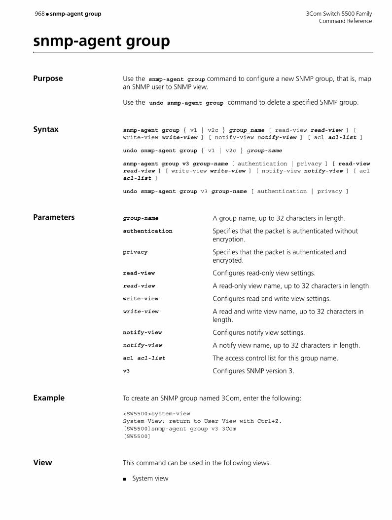
968 ● snmp-agent group 3Com Switch 5500 Family Command Reference
snmp-agent group
Purpose Use the snmp-agent group command to configure a new SNMP group, that is, map an SNMP user to SNMP view.
Use the undo snmp-agent group command to delete a specified SNMP group.
Syntax snmp-agent group { v1 | v2c } group_name [ read-view read-view ] [ write-view write-view ] [ notify-view notify-view ] [ acl acl-list ]
undo snmp-agent group { v1 | v2c } group-name
snmp-agent group v3 group-name [ authentication | privacy ] [ read-view read-view ] [ write-view write-view ] [ notify-view notify-view ] [ acl acl-list ]
undo snmp-agent group v3 group-name [ authentication | privacy ]
Parameters group-name A group name, up to 32 characters in length.
authentication Specifies that the packet is authenticated without encryption.
privacy Specifies that the packet is authenticated and encrypted.
read-view Configures read-only view settings.
read-view A read-only view name, up to 32 characters in length.
write-view Configures read and write view settings.
write-view A read and write view name, up to 32 characters in length.
notify-view Configures notify view settings.
notify-view A notify view name, up to 32 characters in length.
acl acl-list The access control list for this group name.
v3 Configures SNMP version 3.
Example To create an SNMP group named 3Com, enter the following:
<SW5500>system-viewSystem View: return to User View with Ctrl+Z.[SW5500]snmp-agent group v3 3Com[SW5500]
View This command can be used in the following views:
■ System view

3Com Switch 5500 Family snmp-agent group ● 969 Command Reference
Description 3Com recommends that you do not use the notify-view parameter when configuring an SNMP group, for the following reasons:
■ The snmp-agent target-host command automatically generates a notify-view for a user, and adds it to the corresponding group.
■ Any change of the SNMP group notify-view will affect all the users related to this group.

970 ● snmp-agent local-engineid 3Com Switch 5500 Family Command Reference
snmp-agent local-engineid
Purpose Use the snmp-agent local-engineid command to configure a name for a local or remote SNMP engine on the Switch.
Use the undo snmp-agent local-engineid command to restore the default setting of engine ID.
Syntax snmp-agent local-engineid engineid
undo snmp-agent local-engineid
Parameters local-engineid Specifies an engineID for the local SNMPv3 entity.
engineid Specifies the engine ID with a character string, only composed of hexadecimal numbers between 5 and 32 inclusive. The default value is "Enterprise Number + device information".
Example Configure the ID of a local or remote device as 1234512345.
<SW5500>system-viewSystem View: return to User View with Ctrl+Z.<SW5500>snmp-agent local-engineid 1234512345<SW5500>
View This command can be used in the following views:
■ System view
Description Device information is determined according to different products. It can be IP address, MAC address or user defined text. However, you must use numbers in hexadecimal form.
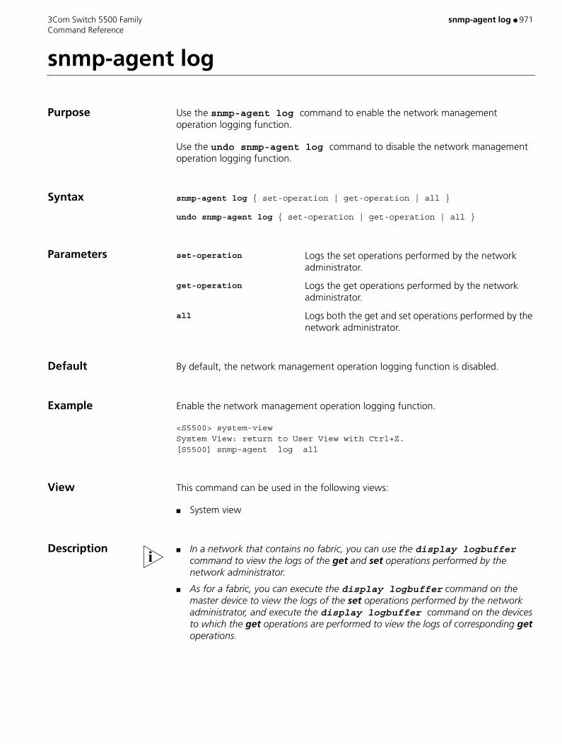
3Com Switch 5500 Family snmp-agent log ● 971 Command Reference
snmp-agent log
Purpose Use the snmp-agent log command to enable the network management operation logging function.
Use the undo snmp-agent log command to disable the network management operation logging function.
Syntax snmp-agent log { set-operation | get-operation | all }
undo snmp-agent log { set-operation | get-operation | all }
Parameters set-operation Logs the set operations performed by the network administrator.
get-operation Logs the get operations performed by the network administrator.
all Logs both the get and set operations performed by the network administrator.
Default By default, the network management operation logging function is disabled.
Example Enable the network management operation logging function.
<S5500> system-viewSystem View: return to User View with Ctrl+Z.[S5500] snmp-agent log all
View This command can be used in the following views:
■ System view
Description ■ In a network that contains no fabric, you can use the display logbuffer command to view the logs of the get and set operations performed by the network administrator.
■ As for a fabric, you can execute the display logbuffer command on the master device to view the logs of the set operations performed by the network administrator, and execute the display logbuffer command on the devices to which the get operations are performed to view the logs of corresponding get operations.

972 ● snmp-agent mib-view 3Com Switch 5500 Family Command Reference
snmp-agent mib-view
Purpose Use the snmp-agent mib-view command to create or update the view information.
Use the undo snmp-agent mib-view command to delete the view information
Syntax snmp-agent mib-view { included | excluded } view-name oid-tree
undo snmp-agent mib-view view-name
Parameters included Includes this MIB subtree.
excluded Excludes this MIB subtree.
view-name Specifies the view name, consisting of a character string from 1 to 32 characters long.
oid-tree MIB object subtree. It can be a character string of the variable OID, or a variable name, consisting of a character string from 1 to 255 characters long.
Default By default, the view name is v1default. OID is 1.3.6.1.
Example Create a view that consists of all the objects of MIB-II.
<SW5500>system-viewSystem View: return to User View with Ctrl+Z.[SW5500]snmp-agent mib-view included mib2 1.3.6.1.3 [SW5500]
View This command can be used in the following views:
■ System view
Description Both the character string of OID and the node name can be input as parameter.
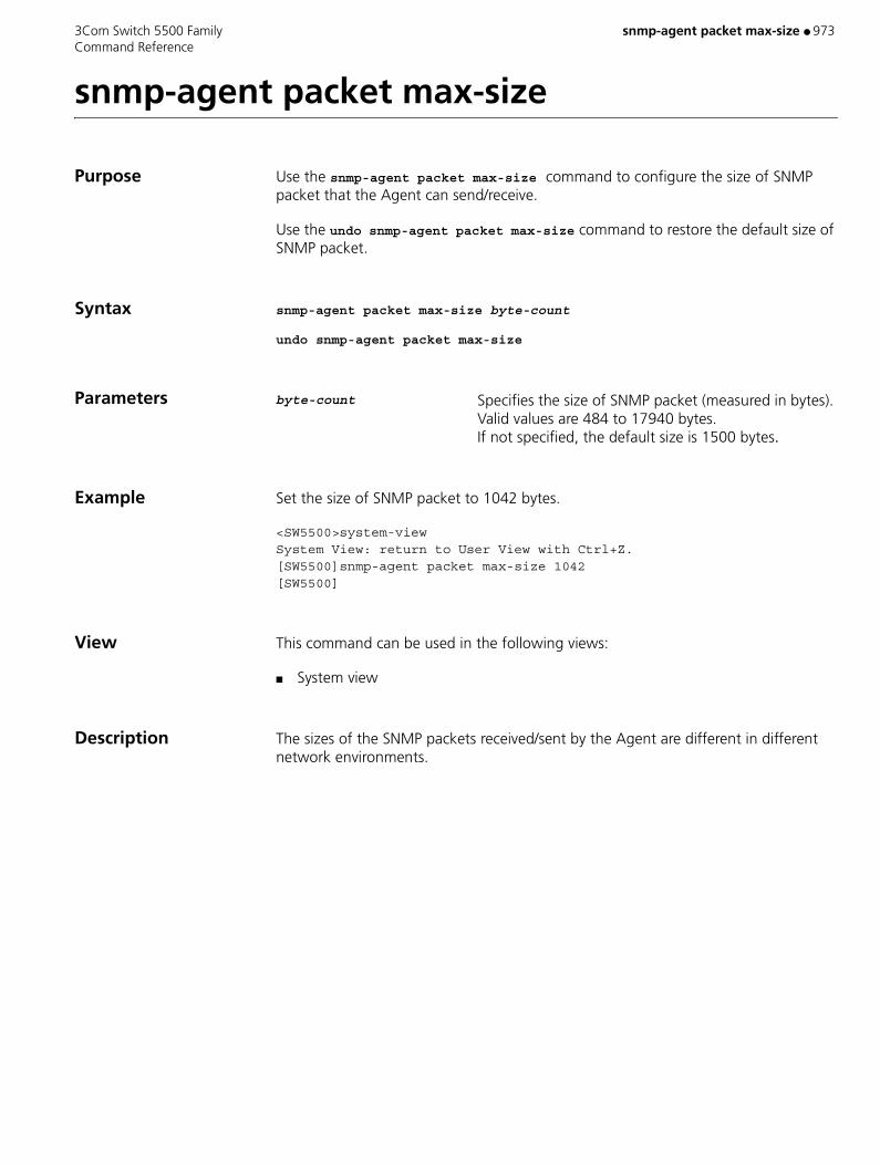
3Com Switch 5500 Family snmp-agent packet max-size ● 973 Command Reference
snmp-agent packet max-size
Purpose Use the snmp-agent packet max-size command to configure the size of SNMP packet that the Agent can send/receive.
Use the undo snmp-agent packet max-size command to restore the default size of SNMP packet.
Syntax snmp-agent packet max-size byte-count
undo snmp-agent packet max-size
Parameters byte-count Specifies the size of SNMP packet (measured in bytes). Valid values are 484 to 17940 bytes. If not specified, the default size is 1500 bytes
Example Set the size of SNMP packet to 1042 bytes.
<SW5500>system-viewSystem View: return to User View with Ctrl+Z.[SW5500]snmp-agent packet max-size 1042[SW5500]
View This command can be used in the following views:
■ System view
Description The sizes of the SNMP packets received/sent by the Agent are different in different network environments.

974 ● snmp-agent sys-info 3Com Switch 5500 Family Command Reference
snmp-agent sys-info
Purpose Use the snmp-agent sys-info command to set system information such as geographical location of the device, contact information for system maintenance and version information of running SNMP.
Use the undo snmp-agent sys-info location command to restore the default value.
Syntax snmp-agent sys-info { contact sysContact | location sysLocation | version { { v1 | v2c | v3 } * | all } }
undo snmp-agent sys-info [ { contact | location }* | version { { v1 | v2c | v3 }* | all } ]
Parameters sysContact A character string describing the system maintenance contact. Valid values are 1 to 255 characters long. If not specified, the default contact information is "3Com Marlborough USA".
sysLocation A character string to describe the system location. If not specified, the default character string is "Marlborough USA".
version Version of running SNMP.
v1 SNMP V1.
v2c SNMP V2C.
v3 SNMP V3.
all All SNMP version (includes SNMP V1, SNMP V2C, SNMP V3).
Example Set system location as Building 3/Room 214.
<SW5500>system-viewSystem View: return to User View with Ctrl+Z.[SW5500]snmp-agent sys-info location Building 3/Room 214[SW5500]
View This command can be used in the following views:
■ System view

3Com Switch 5500 Family snmp-agent target-host ● 975 Command Reference
snmp-agent target-host
Purpose Use the snmp-agent target-host command to select and configure the host that you want to receive SNMP notification.
Use the undo snmp-agent target-host command to cancel the host currently configured to receive SNMP notification.
Syntax snmp-agent target-host trap address udp-domain host-addr [ udp-port udp-port-number ] params securityname community-string [ v1 | v2c | v3 [ authentication | privacy ] ]
undo snmp-agent target-host host-addr securityname community-string
Parameters trap Specifies the host to receive traps or notifications.
address Specifies the transport address to be used in the generation of SNMP messages.
udp-domain Specifies the transport domain over UDP for the target address.
host-addr Specifies the IP address of the destination host.
udp-port udp-port-number Specifies the UDP port number of the host to receive the SNMP notification.
params Specifies the SNMP target information to be used in the generation of SNMP messages.
community-string Specifies the community name, up to 32 characters in length.
v1 Specifies SNMP version 1.
v2c Specifies SNMP version 2C.
v3 Specifies SNMP version 3.
authentication Specifies that the packet is authenticated without encryption.
privacy Specifies that the packet is authenticated and encrypted.
Example To enable Trap messages to be sent to 2.2.2.2 with a community name of comaccess, enter the following:
<SW5500>system-viewSystem View: return to User View with Ctrl+Z.[SW5500]snmp-agent trap enable[SW5500]snmp-agent target-host trap address udp-domain 2.2.2.2 params securityname comaccess[SW5500]
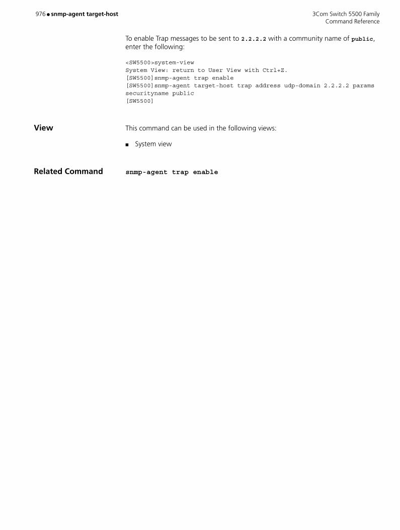
976 ● snmp-agent target-host 3Com Switch 5500 Family Command Reference
To enable Trap messages to be sent to 2.2.2.2 with a community name of public, enter the following:
<SW5500>system-viewSystem View: return to User View with Ctrl+Z.[SW5500]snmp-agent trap enable[SW5500]snmp-agent target-host trap address udp-domain 2.2.2.2 params securityname public[SW5500]
View This command can be used in the following views:
■ System view
Related Command snmp-agent trap enable

3Com Switch 5500 Family snmp-agent trap enable ● 977 Command Reference
snmp-agent trap enable
Purpose Use the snmp-agent trap enable command to enable the device to send Trap message.
Use the undo snmp-agent trap enable command to disable Trap message sending.
Syntax snmp-agent trap enable [ configuration | flash | ospf [ process-id ] [ ospf-trap-list ] | standard [ authentication | coldstart | linkdown | linkup | warmstart ]* | system ]
undo snmp-agent trap enable [ bgp [ backwardtransition ] [ established ] | configuration | flash | ospf [ process-id ] [ ospf-trap-list ] | standard [ authentication | coldstart | linkdown | linkup | warmstart ]* | system ]
Parameters configuration Configure to send SNMP configuration Trap packets.
flash Configure to send SNMP flash Trap packets.
ospf [ process-id ] [ ospf-trap-list ] Configure to send the OSPF trap packets. process-id is
the ID of the OSPF process, ranging from 1 to 65535. ospf-trap-list is the list of OSPF trap information.
standard [ authentication | coldstart | linkdown | linkup | warmstart ]* Configure to send standard Trap messages.
authentication Configure to send SNMP authentication Trap messages when authentication fails.
coldstart Configure to send SNMP cold start Trap messages when switch is rebooted.
linkdown Configure to send SNMP link down Trap messages when switch port turns down.
linkup Configure to send SNMP link up Trap messages when switch port turns up.
warmstart Configure to send SNMP warm start Trap messages when snmp is re-enabled.
system Configure to send SysMib trap messages.
Default By default, Trap message sending is disabled.

978 ● snmp-agent trap enable 3Com Switch 5500 Family Command Reference
Example Enable to send the trap packet of SNMP authentication failure to 10.1.1.1. The community name is 3Com.
<SW5500>system-viewSystem View: return to User View with Ctrl+Z.[SW5500]snmp-agent trap enable standard authentication[SW5500]snmp-agent target-host trap address udp-domain 10.1.1.1 param securityname 3Com[SW5500]
View This command can be used in the following views:
■ System view
Description The snmp-agent trap enable command and the snmp-agent target-host command should be used at the same time. The snmp-agent target-host command specifies which hosts can receive Trap message. To send Trap messages, at least one snmp-agent target-host command should be configured.
3Com Switch 5500 Family snmp-agent trap enable ospf ● 979 Command Reference
snmp-agent trap enable ospf
Purpose Use the snmp-agent trap enable ospf command to enable the OSPF TRAP function.
Use the undo snmp-agent trap enable ospf command to disable the OSPF TRAP function.
Syntax snmp-agent trap enable ospf [ process-id ] [ ifstatechange | virifstatechange | nbrstatechange | virnbrstatechange | ifcfgerror | virifcfgerror | ifauthfail | virifauthfail | ifrxbadpkt | virifrxbadpkt | txretransmit | viriftxretransmit | originatelsa | maxagelsa | lsdboverflow | lsdbapproachoverflow ]
undo snmp-agent trap enable ospf [ process-id ] [ ifstatechange | virifstatechange | nbrstatechange | virnbrstatechange | ifcfgerror | virifcfgerror | ifauthfail | virifauthfail | ifrxbadpkt | virifrxbadpkt | txretransmit | viriftxretransmit | originatelsa | maxagelsa | lsdboverflow | lsdbapproachoverflow ]
Parameters process-id The process ID of OSPF. The command is applied to all current OSPF processes if you do not specify a process ID.
ifstatechange, virifstatechange, nbrstatechange, virnbrstatechange, ifcfgerror, virifcfgerror, ifauthfail, virifauthfail, ifrxbadpkt, virifrxbadpkt, txretransmit, viriftxretransmit, originatelsa, maxagelsa, lsdboverflow, lsdbapproachoverflow Types of TRAP packets that the switch produces in case
of OSPF anomalies.
Default By default, the switch does not send TRAP packets in case of OSPF anomalies.
Example Enable the TRAP function for OSPF process 100.
<SW5500>system-viewSystem View: return to User View with Ctrl+Z.[SW5500]snmp-agent trap enable ospf 100
View This command can be used in the following views:
■ System view

980 ● snmp-agent trap enable ospf 3Com Switch 5500 Family Command Reference
Description This command cannot be applied to the OSPF processes that are started after the command is executed.
3Com Switch 5500 Family snmp-agent trap life ● 981 Command Reference
snmp-agent trap life
Purpose Use the snmp-agent trap life command to set the timeout of Trap packets.
Use the undo snmp-agent trap life command to restore the default value.
Syntax snmp-agent trap life seconds
undo snmp-agent trap life
Parameters seconds Specifies the timeouts. Valid values are 1 to 2592000 seconds. If not specified, the default timeout interval is 120 seconds.
Example Configure the timeout interval of Trap packet as 60 seconds.
<SW5500>system-viewSystem View: return to User View with Ctrl+Z.[SW5500]snmp-agent trap life 60[SW5500]
View This command can be used in the following views:
■ System view
Description The set timeout of Trap packet is represented by seconds. If time exceeds seconds, this Trap packet will be discarded.
Related Commands ■ snmp-agent trap enable
■ snmp-agent target-host
982 ● snmp-agent trap queue-size 3Com Switch 5500 Family Command Reference
snmp-agent trap queue-size
Purpose Use the snmp-agent trap queue-size command to configure the information queue length of Trap packet sent to destination host.
Use the undo snmp-agent trap queue-size command to restore the default value.
Syntax snmp-agent trap queue-size length
undo snmp-agent trap queue-size
Parameters length Length of queue. Valid values are 1 to 1000. If not specified, the default length is 100.
Example Configure the queue length to 200.
<SW5500>system-viewSystem View: return to User View with Ctrl+Z.[SW5500]snmp-agent trap queue-size 200[SW5500]
View This command can be used in the following views:
■ System view
Related Commands ■ snmp-agent trap enable
■ snmp-agent trap life

3Com Switch 5500 Family snmp-agent trap source ● 983 Command Reference
snmp-agent trap source
Purpose Use the snmp-agent trap source command to specify the source address for sending Traps.
Use the undo snmp-agent trap source command to cancel the source address for sending Traps.
Syntax snmp-agent trap source vlan-interface vlan-id
undo snmp-agent trap source
Parameters vlan-id Specifies the VLAN interface ID. Valid values are 1 to 4094.
Example Configure the IP address of the VLAN interface 1 as the source address for transmitting the Trap packets.
<SW5500>system-viewSystem View: return to User View with Ctrl+Z.[SW5500]snmp-agent trap source vlan-interface 1[SW5500]
View This command can be used in the following views:
■ System view
984 ● snmp-agent usm-user 3Com Switch 5500 Family Command Reference
snmp-agent usm-user
Purpose Use the snmp-agent usm-user command to add a new user to an SNMP group, and reference the ACL to perform ACL control to the network management users by acl acl-number.
Use the undo snmp-agent usm-user command to remove the user from the related SNMP group as well as the configuration of the ACL control of the user.
Syntax For Versions V1 and V2C:
snmp-agent usm-user { v1 | v2c } user-name group-name [ acl acl-number ]
undo snmp-agent usm-user { v1 | v2c } user-name group-name
For Version V3:
snmp-agent usm-user v3 user-name group-name [ authentication-mode { md5 | sha } auth-password ] [ acl acl-number ]
undo snmp-agent usm-user v3 user-name group-name { local | engineid engineid-string }
Parameters v1 V 1 security mode.
v2c V 2 security mode.
v3 V 3 security mode.
user-name The user name. Valid values are from 1 to 32 bytes.
group-name The corresponding group name of the user. Valid values are from 1 to 32 bytes.
authentication-mode Specifies the security level to "to be authenticated"
md5 Specifies the authentication protocol as HMAC-MD5-96.
sha Specifies the authentication protocol as HMAC-SHA-96.
auth-password Authentication password, consisting of a character string from 1 to 64 bytes.
privacy Specifies the security level as encryption.
des56 Specifies the DES encryption protocol.
priv-password Encryption password, character string, ranging from 1 to 64 bytes.
acl acl-number The number identifier of basic number-based ACLs, ranging from 2000 to 2999.
local Local entity user.

3Com Switch 5500 Family snmp-agent usm-user ● 985 Command Reference
engineid Specifies the engine ID related to the user.
engineid-string Engine ID character string.
Example Add a user "John" to the SNMP group "Mygroup". Specify the security level to "to be authenticated", the authentication protocol to HMAC-MD5-96 and the authentication password to "hello", and reference the ACL 2002 to perform ACL control to the network management users (basic ACL 2002 has already been defined).
<SW5500>system-viewSystem View: return to User View with Ctrl+Z[SW5500] snmp-agent usm-user v3 John Mygroup authentication-mode md5 hello acl 2002
View This command can be used in the following views:
■ System view
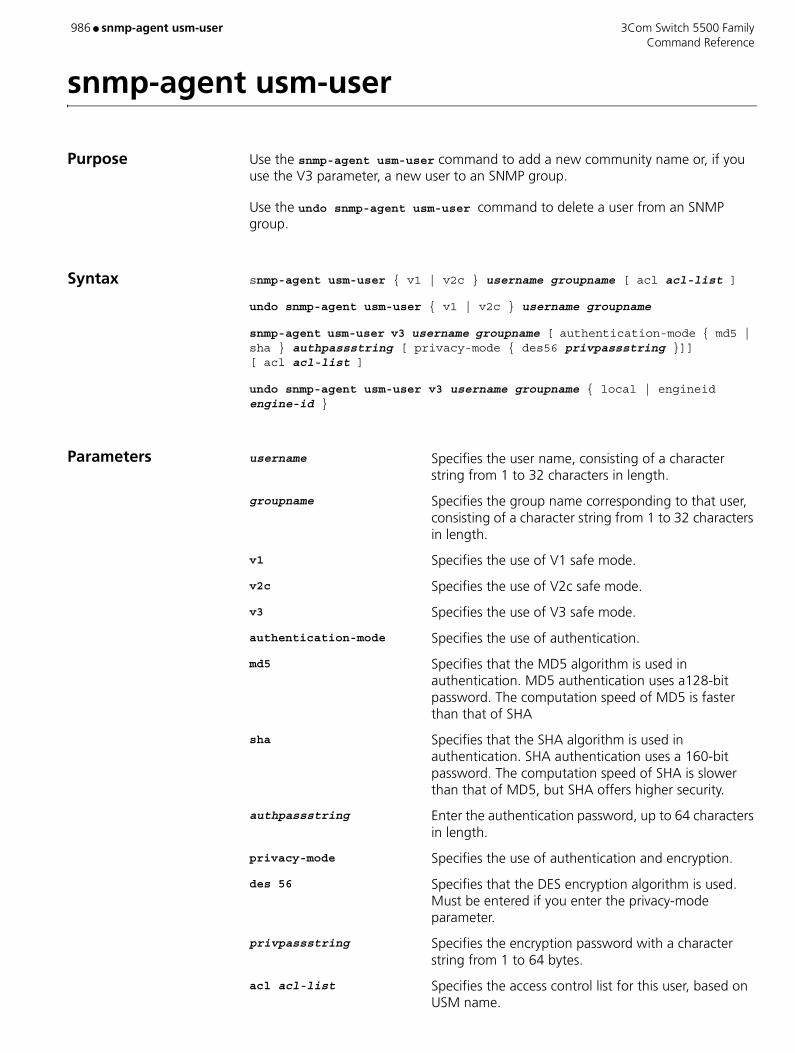
986 ● snmp-agent usm-user 3Com Switch 5500 Family Command Reference
snmp-agent usm-user
Purpose Use the snmp-agent usm-user command to add a new community name or, if you use the V3 parameter, a new user to an SNMP group.
Use the undo snmp-agent usm-user command to delete a user from an SNMP group.
Syntax snmp-agent usm-user { v1 | v2c } username groupname [ acl acl-list ]
undo snmp-agent usm-user { v1 | v2c } username groupname
snmp-agent usm-user v3 username groupname [ authentication-mode { md5 | sha } authpassstring [ privacy-mode { des56 privpassstring }]] [ acl acl-list ]
undo snmp-agent usm-user v3 username groupname { local | engineid engine-id }
Parameters username Specifies the user name, consisting of a character string from 1 to 32 characters in length.
groupname Specifies the group name corresponding to that user, consisting of a character string from 1 to 32 characters in length.
v1 Specifies the use of V1 safe mode.
v2c Specifies the use of V2c safe mode.
v3 Specifies the use of V3 safe mode.
authentication-mode Specifies the use of authentication.
md5 Specifies that the MD5 algorithm is used in authentication. MD5 authentication uses a128-bit password. The computation speed of MD5 is faster than that of SHA
sha Specifies that the SHA algorithm is used in authentication. SHA authentication uses a 160-bit password. The computation speed of SHA is slower than that of MD5, but SHA offers higher security.
authpassstring Enter the authentication password, up to 64 characters in length.
privacy-mode Specifies the use of authentication and encryption.
des 56 Specifies that the DES encryption algorithm is used. Must be entered if you enter the privacy-mode parameter.
privpassstring Specifies the encryption password with a character string from 1 to 64 bytes.
acl acl-list Specifies the access control list for this user, based on USM name.
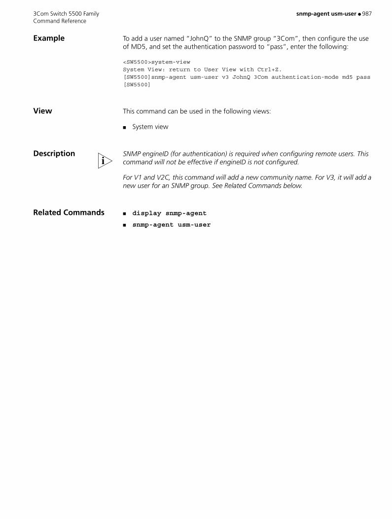
3Com Switch 5500 Family snmp-agent usm-user ● 987 Command Reference
Example To add a user named “JohnQ” to the SNMP group “3Com”, then configure the use of MD5, and set the authentication password to “pass”, enter the following:
<SW5500>system-viewSystem View: return to User View with Ctrl+Z.[SW5500]snmp-agent usm-user v3 JohnQ 3Com authentication-mode md5 pass[SW5500]
View This command can be used in the following views:
■ System view
Description SNMP engineID (for authentication) is required when configuring remote users.�This command will not be effective if engineID is not configured.
For V1 and V2C, this command will add a new community name. For V3, it will add a new user for an SNMP group. See Related Commands below.
Related Commands ■ display snmp-agent
■ snmp-agent usm-user

988 ● snmp-host 3Com Switch 5500 Family Command Reference
snmp-host
Purpose Use the snmp-host command to configure the public SNMP host for members inside a cluster on the management device.
Use the undo snmp-host command to cancel the public SNMP host configuration.
Syntax snmp-host ip-address
undo snmp-host
Parameters ip-address IP address of the SNMP host configured for the cluster.
Default By default, no public SNMP host is configured.
Example Configure the IP address of SNMP host for the cluster on the management device.
<aaa_0.S5500>system-viewSystem View: return to User View with Ctrl+Z.[aaa_0.S5500]cluster[aaa_0.S5500-cluster] snmp-host 1.0.0.9
View This command can be used in the following views:
■ Cluster view
Description Only after you configure the IP address of the network management site for the cluster, cluster members can send the trap information to the site through the management device.
These commands can only be executed on the management device.
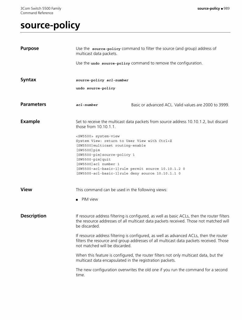
3Com Switch 5500 Family source-policy ● 989 Command Reference
source-policy
Purpose Use the source-policy command to filter the source (and group) address of multicast data packets.
Use the undo source-policy command to remove the configuration.
Syntax source-policy acl-number
undo source-policy
Parameters acl-number Basic or advanced ACL. Valid values are 2000 to 3999.
Example Set to receive the multicast data packets from source address 10.10.1.2, but discard those from 10.10.1.1.
<SW5500> system-viewSystem View: return to User View with Ctrl+Z[SW5500]multicast routing-enable[SW5500]pim[SW5500-pim]source-policy 1[SW5500-pim]quit[SW5500]acl number 1[SW5500-acl-basic-1]rule permit source 10.10.1.2 0[SW5500-acl-basic-1]rule deny source 10.10.1.1 0
View This command can be used in the following views:
■ PIM view
Description If resource address filtering is configured, as well as basic ACLs, then the router filters the resource addresses of all multicast data packets received. Those not matched will be discarded.
If resource address filtering is configured, as well as advanced ACLs, then the router filters the resource and group addresses of all multicast data packets received. Those not matched will be discarded.
When this feature is configured, the router filters not only multicast data, but the multicast data encapsulated in the registration packets.
The new configuration overwrites the old one if you run the command for a second time.

990 ● speed 3Com Switch 5500 Family Command Reference
speed
Purpose Use the speed command to configure the transmission rate on the AUX (Console) port.
Use the undo speed command to restore the default rate.
Syntax speed speed-value
undo speed
Parameters speed-value Specifies the transmission rate on the AUX (Console) port in bits per second (bps). Valid values are any of the following: 300, 600, 1200, 2400, 4800, 9600, 19200, 38400, 57600, 115200 or 4096000. If not specified, the default rate is 19200 bps.
Example To configure the transmission speed on the AUX (Console) port as 9600 b/s, enter the following:
<SW5500>system-viewSystem View: return to User View with Ctrl+Z.[SW5500]user-interface aux 0[SW5500-ui-aux0]speed 9600
View This command can be used in the following views:
■ User Interface view
Description This command can only be performed in AUX User Interface view

3Com Switch 5500 Family speed ● 991 Command Reference
speed
Purpose Use the speed command to configure the port speed.
Use the undo speed command to restore the default speed. By default, the speed is auto.
Syntax For a 100 Mbps Ethernet port, the parameters for this command are as follows:
speed { 10 | 100 | auto }
For a 1000 Mbps Ethernet port, the parameters for this command are as follows:
speed { 10 | 100 | 1000 | auto }
The undo form of this command is:
undo speed
Parameters 10 Sets the port speed to 10 Mbps.
100 Sets the port speed to 100 Mbps.
1000 Sets the port speed to 1000 Mbps. (Only available on Gigabit ports).
auto Sets the port speed to auto-negotiation.
Example To configure the port speed of port Ethernet1/0/1 to 10 Mbps, enter the following:
<SW5500>system-viewSystem View: return to User View with Ctrl+Z.[SW5500]interface ethernet 1/0/1[SW5500-Ethernet1/0/1]speed 10[SW5500-Ethernet1/0/1]
View This command can be used in the following views:
■ Ethernet Port view
Related Command duplex

992 ● spf-schedule-interval 3Com Switch 5500 Family Command Reference
spf-schedule-interval
Purpose Using the spf-schedule-interval command, you can configure the route calculation interval of OSPF.
Using the undo spf-schedule-interval command, you can restore the default setting.
Syntax spf-schedule-interval interval
undo spf-schedule-interval
Parameters interval Specifies the SPF route calculation interval for OSPF, in seconds. Valid values are 1 to 10. If not specified, the default value is 5 seconds.
Example To set the OSPF route calculation interval of the Switch 5500 to 6 seconds, enter the following:
<SW5500>system-viewSystem View: return to User View with Ctrl+Z.[SW5500]router id 1.1.1.1[SW5500]ospf[SW5500-ospf]spf-schedule-interval 6
View This command can be used in the following views:
■ OSPF view
Description According to the Link State Database (LSDB), the router running OSPF can calculate the shortest path tree, with itself as the root, and determine the next hop to the destination network according to the shortest path tree. By adjusting the SPF calculation interval, you can decrease the frequency of network changes and unnecessary consumption of bandwidth and router resources.
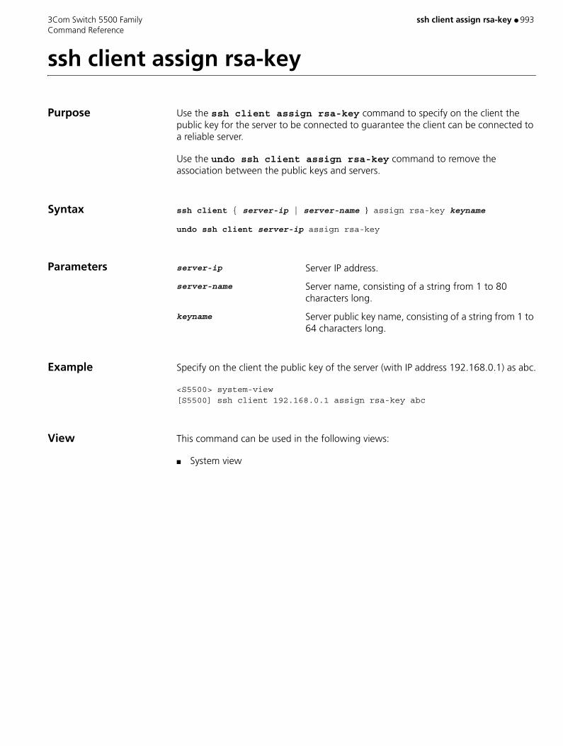
3Com Switch 5500 Family ssh client assign rsa-key ● 993 Command Reference
ssh client assign rsa-key
Purpose Use the ssh client assign rsa-key command to specify on the client the public key for the server to be connected to guarantee the client can be connected to a reliable server.
Use the undo ssh client assign rsa-key command to remove the association between the public keys and servers.
Syntax ssh client { server-ip | server-name } assign rsa-key keyname
undo ssh client server-ip assign rsa-key
Parameters server-ip Server IP address.
server-name Server name, consisting of a string from 1 to 80 characters long.
keyname Server public key name, consisting of a string from 1 to 64 characters long.
Example Specify on the client the public key of the server (with IP address 192.168.0.1) as abc.
<S5500> system-view[S5500] ssh client 192.168.0.1 assign rsa-key abc
View This command can be used in the following views:
■ System view

994 ● ssh client first-time enable 3Com Switch 5500 Family Command Reference
ssh client first-time enable
Purpose Use the ssh client first-time enable command to configure the client to run the initial authentication.
Use the undo ssh client first-time command to remove the configuration.
Syntax ssh client first-time enable
undo ssh client first-time
Parameters None
Default By default, the client runs the initial authentication.
Example Configure the client to run the initial authentication.
<S5500> system-view[S5500] ssh client first-time enable
View This command can be used in the following views:
■ System view
Description In the initial authentication, if the SSH client does not have the public key for the server which it accesses for the first time, the client continues to access the server and save locally the public key of the server. Then at the next access, the client can authenticate the server with the public key saved locally.
When the initial authentication function is not available, the client does not access the server if it does not have the public key of the server locally. In this case, you need first to save the public key of the target server to the client in other ways.

3Com Switch 5500 Family ssh server authentication-retries ● 995 Command Reference
ssh server authentication-retries
Purpose Use the ssh server authentication-retries command to set authentication retry number for SSH connections.
Use the undo ssh server authentication-retries command to restore the default authentication retry number. The default value takes effect at next login.
Syntax ssh server authentication-retries times
undo ssh server authentication-retries
Parameters times Authentication retry number. Valid values are 1 to 5. If not specified, the default is 3.
Example Set the authentication retry number to 4.
<S5500> system-view[S5500] ssh server authentication-retries 4
View This command can be used in the following views:
■ System view
Description As the authentication retry number increases by one when a client sends a public key to the server, configure a value larger than two for the times argument if you specify the password-public authentication type using the ssh user authentication-type command.
Related Command display ssh server
996 ● ssh-server source-interface 3Com Switch 5500 Family Command Reference
ssh-server source-interface
Purpose Use the ssh-server source-interface command to specify source interface for the SSH server. If you specify a nonexistent interface in the command, your configuration fails.
Use the undo ssh-server source-interface command to clear the source interface configuration. After that, the source address in the packets sent to the SSH2 client is determined by the system.
Syntax ssh-server source-interface interface-type interface-number
undo ssh-server source-interface
Parameters interface-type Source interface type.
interface-number Source interface number.
Example Specify source interface for the SSH server.
<S5500> system-viewSystem View: return to User View with Ctrl+Z.[S5500] ssh-server source-interface Vlan-interface 2
View This command can be used in the following views:
■ System view
3Com Switch 5500 Family ssh server rekey-interval ● 997 Command Reference
ssh server rekey-interval
Purpose Use the ssh server rekey-interval command to define update interval of server key pair.
Use the undo ssh server rekey-interval command to cancel the current setting.
Syntax ssh server rekey-interval hours
undo ssh server rekey-interval
Parameters hours Defines key update interval (in hours). Valid values are 1 to 24.
Default By default, system doesn’t update the server key.
Example <SW5500>system-viewSystem View: return to User View with Ctrl+Z.[SW5500]ssh server rekey-interval 3[SW5500]
View This command can be used in the following views:
■ System view
Related Command display ssh server

998 ● ssh-server source-ip 3Com Switch 5500 Family Command Reference
ssh-server source-ip
Purpose Use the ssh-server source-ip ip-addr command to specify source IP address for the SSH server.
Use the undo ssh-server source-ip command to clear the source IP address configuration. After that, the source address in the packets sent to the SSH client is determined by the system.
Syntax ssh-server source-ip ip-addr
undo ssh-server source-ip
Parameters ip-addr Source IP address. If the ip-addr in the command is not an address of the device, your configuration fails.
Example Specify source IP address for the SSH server.
<S5500> system-viewSystem View: return to User View with Ctrl+Z.[S5500] ssh-server source-ip 192.168.0.1
View This command can be used in the following views:
■ System view

3Com Switch 5500 Family ssh server timeout ● 999 Command Reference
ssh server timeout
Purpose Use the ssh server timeout command to set authentication timeout time for SSH connections.
Use the undo ssh server timeout command to restore the default timeout time. The default value takes effect at next login.
Syntax ssh server timeout seconds
undo ssh server timeout
Parameters seconds Authentication timeout time (in seconds). Valid values are 1 to 120. If not specified, the default is 60 seconds.
Example Set the authentication timeout time to 80 seconds.
<S5500> system-view[S5500] ssh server timeout 80
View This command can be used in the following views:
■ System view
Related Command display ssh server
1000 ● ssh user assign rsa-key 3Com Switch 5500 Family Command Reference
ssh user assign rsa-key
Purpose Use the ssh user assign rsa-key command to allocate public keys to SSH users.
Use the undo ssh user assign rsa-key command to remove the association between the public keys and SSH users. The configuration takes effect at the next login.
Syntax ssh user username assign rsa-key keyname
undo ssh user username assign rsa-key
Parameters username SSH user name, consisting of a string from 1 to 80 characters long.
keyname Client public key name, consisting of a string from 1 to 64 characters long.
Example Set the client public key for the zhangsan user to key1.
<S5500> system-view[S5500] ssh user zhangsan assign rsa-key key1[S5500]
View This command can be used in the following views:
■ System view
Description If the user already has a public key, the new public key overrides the old one.
Related Command display ssh user-information
3Com Switch 5500 Family ssh user authentication-type ● 1001 Command Reference
ssh user authentication-type
Purpose Use the ssh user authentication-type command to define on the server the available authentication type for an SSH user.
Use the undo ssh user authentication-type command to restore the default setting.
Syntax ssh user username authentication-type { password | rsa | password-publickey | all }
undo ssh user username authentication-type
Parameters username Valid SSH user name, consisting of a string from 1 to 80 characters long.
password Specifies the authentication type as password.
rsa Specifies the authentication type as RSA public key.
password-publickey Specifies the authentication type as both password and RSA public key. That is, the user can pass the authentication only if both the password and RSA public key are correct.
For the authentication type specified by the password-publickey keyword,
■ Users using SSHv1 can log onto a switch if they pass one of the authentications.
■ Users using SSHv2 need to pass both of the authentications to log onto a switch.
all Specifies the authentication type as either password or RSA public key. That is, the user can pass the authentication if either the password or RSA public key is correct.
Default By default, no authentication type is specified for new users, so they cannot access the switch.
New users must specify authentication type. Otherwise, they cannot access the switch. The new authentication type configured takes effect at the next login.
Example Set the authentication type for the zhangsan user as password.
<S5500> system-view[S5500] ssh user zhangsan authentication-type password
View This command can be used in the following views:

1002 ● ssh user authentication-type 3Com Switch 5500 Family Command Reference
■ System view
Description This command defines available authentication type on the server. The actual authentication type, however, is determined by the client.
Related Command display ssh user-information
3Com Switch 5500 Family ssh user service-type ● 1003 Command Reference
ssh user service-type
Purpose Use the ssh user service-type command to specify service type for a user.
Use the undo ssh user service-type command to restore the default service type for the SSH user in the system.
Syntax ssh user username service-type { stelnet | sftp | all }
undo ssh user username service-type
Parameters username Local user name or the user name defined on the remote RADIUS server, consisting of a string from 1 to 80 characters long.
stelnet Sets the service type to Telnet. If no service type is specified, Telnet is used as the default.
sftp Sets the service type to SFTP.
all Includes Telnet and SFTP two services types.
Example Specify SFTP service for SSH user zhangsan.
<S5500> system-view[S5500] ssh user zhangsan service-type sftp
View This command can be used in the following views:
■ System view
Related Command display ssh user-information
1004 ● ssh user username authentication-type 3Com Switch 5500 Family Command Reference
ssh user username authentication-type
Purpose Use the ssh user username authentication-type command to define authentication type for a designated user.
Use the undo ssh user username authentication-type command to restore the default mode in which logon fails.
Syntax ssh user username authentication-type { all | password | rsa }
undo ssh user username authentication-type
Parameters username Valid local user name or user name defined by remote RADIUS system.
all Specifies authentication type as password and RSA.
password Specifies authentication type as password.
rsa Specifies authentication type as RSA.
Default By default, user can’t logon the switch through SSH or TELNET, so you have to specify authentication type for a new user. The new configuration takes effects at the next logon.
Example To specify jsmith’s authentication type as password, enter the following:
<SW5500>system-viewSystem View: return to User View with Ctrl+Z.[SW5500]ssh user jsmith authentication-type password[SW5500]
View This command can be used in the following views:
■ System view
Related Command display ssh user-information
3Com Switch 5500 Family ssh2 ● 1005 Command Reference
ssh2
Purpose Use the ssh2 command to enable the connection between SSH client and server, define key exchange algorithm preference, encryption algorithm preference and HMAC algorithm preference on the server and client.
Syntax ssh2 { host-ip | host-name } [ port-num ] [ prefer_kex { dh_group1 | dh_exchange_group } ] [ prefer_ctos_cipher { des | aes128 } ] [ prefer_stoc_cipher { des | aes128 } ] [ prefer_ctos_hmac { sha1 | sha1_96 | md5 | md5_96 } ] [ prefer_stoc_hmac { sha1 | sha1_96 | md5 | md5_96 } ]
Parameters host-ip Server IP address.
host-name Server name, consisting of a string from 1 to 20 characters long.
port-num Server port number. Valid values are 0 to 65,535. If not specified, the default is 22.
prefer_kex Key exchange algorithm preference. Choose one of the two algorithms available.
dh_group1 Diffie-Hellman-group1-sha1 key exchange algorithm. If not specified, Diffie-Hellman-group1-sha1 key exchange is the default algorithm.
dh_exchange_group Diffie-Hellman-group-exchange-sha1 key exchange algorithm.
prefer_ctos_cipher Encryption algorithm preference from the client to server. If not specified, the default is AES128.
prefer_stoc_cipher Encryption algorithm preference from the server to client. If not specified, the default is AES128.
des DES_cbc encryption algorithm.
aes128 AES_128 encryption algorithm.
prefer_ctos_hmac HMAC algorithm preference from the client to server. If not specified, the default is SHA1_96.
prefer_stoc_hmac HMAC algorithm preference from the server to client. If not specified, the default is SHA1_96.
sha1 HMAC-SHA1 algorithm.
sha1_96 HMAC-SHA1_96 algorithm.
md5 HMAC-MD5 algorithm.
md5_96 HMAC-MD5-96 algorithm.
1006 ● ssh2 3Com Switch 5500 Family Command Reference
Example Log into the SSH 2.0 server with IP address 10.214.50.51 and make these settings:
■ Key exchange algorithm preference as dh_exchange_group
■ encryption algorithm preference from the server to client as aes128
■ HMAC algorithm preference from the client to server as md5
■ HMAC algorithm preference from the server to client as sha1_96
<S5500> system-view[S5500] ssh2 10.214.50.51 prefer_kex dh_exchange_group prefer_stoc_cipher aes128 prefer_ctos_hmac md5 prefer_stoc_hmac sha1_96
View This command can be used in the following views:
■ System view

3Com Switch 5500 Family ssh2 source-interface ● 1007 Command Reference
ssh2 source-interface
Purpose Use the ssh2 source-interface command to specify source interface for the SSH2 client.
Use the undo ssh2 source-interface command to clear the source interface configuration. After that, the source address in the packets sent to the SSH2 server is determined by the system.
Syntax ssh2 source-interface interface-type interface-number
undo ssh2 source-interface
Parameters interface-type Source interface type. If you specify a nonexistent interface in the command, your configuration fails.
interface-number Source interface number.
Example Specify source interface for the SSH2 client.
<S5500> system-viewSystem View: return to User View with Ctrl+Z.[S5500] ssh2 source-interface Vlan-interface 1
View This command can be used in the following views:
■ System view
1008 ● ssh2 source-ip 3Com Switch 5500 Family Command Reference
ssh2 source-ip
Purpose Use the ssh2 source-ip command to specify source IP address for the SSH2 client.
Use the undo ssh2 source-ip command to clear the source IP address configuration. After that, the source address in the packets sent to the SSH2 server is determined by the system.
Syntax ssh2 source-ip ip-addr
undo ssh2 source-ip
Parameters ip-addr Source IP address. If the ip-addr in the command is not an address of the device, your configuration fails.
Example Specify source IP address for the SSH2 client.
<S5500> system-viewSystem View: return to User View with Ctrl+Z.[S5500] ssh2 source-ip 192.168.1.1
View This command can be used in the following views:
■ System view
3Com Switch 5500 Family standby detect-group ● 1009 Command Reference
standby detect-group
Purpose Use the standby detect-group command to specify to enable the VLAN interface backup function by using the auto detect function.
Use the undo standby detect-group command to disable the VLAN interface backup function.
Syntax standby detect-group group-number
undo standby detect-group group-number
Parameters group-number Detecting group number. Valid values are 1 to 50.
Example Specify to enable VLAN interface 2 when the result of detecting group 10 is unreachable.
<S5500> system-viewSystem View: return to User View with Ctrl+Z.[S5500] interface vlan-interface 2[S5500-vlan-interface2] standby detect-group 10
View This command can be used in the following views:
■ VLAN Interface view
Description You can enable VLAN interface backup function by auto detecting results in the following ways:
■ Enable the primary interface when the result of the detecting group is reachable.
■ Enable the secondary interface when the result of the detecting group is unreachable.
■ When the link between the primary VLAN interface and the destination comes back up, that is, the result of the detecting group is reachable again, the system enables the primary VLAN interface and shuts down the secondary.
1010 ● state 3Com Switch 5500 Family Command Reference
state
Purpose Use the state command to configure the state of the current ISP domain/current user.
Syntax state { active | block }
Parameters active Configures the current ISP domain (ISP Domain View)/current user (Local User View) as being in active state, that is, the system allows the users in the domain (ISP Domain View) or the current user (Local User View) to request network service.
block Configures the current ISP domain (ISP Domain View)/current user (Local User View) as being in block state, that is, the system does not allow the users in the domain (ISP Domain View) or the current user (Local User View) to request network service.
Default By default, after an ISP domain is created, it is in the active state (in ISP Domain View).
A local user will be active (in Local User View) upon its creation.
Example To set the current ISP domain marlboro.net to be in the block state. The supplicants in this domain cannot request for the network service, enter the following:
<SW5500>system-viewSystem View: return to User View with Ctrl+Z.[SW5500]domain marlboro.net[SW5500-isp-marlboro.net]state block[SW5500-isp-marlboro.net]quitTo set the user 3Com1 to be in the block state, enter the following:[SW5500-user-3Com1]state block
View This command can be used in the following views:
■ ISP Domain view
■ Local User view
Description In ISP Domain View, every ISP can either be in active or block state. If an ISP domain is configured to be active, the users in it can request for network service, while in block state, its users cannot request for any network service, which will not affect the users currently online.
Related Command domain

3Com Switch 5500 Family state ● 1011 Command Reference
state
Purpose Use the state command to configure the state of RADIUS server.
Syntax state { primary | secondary } { accounting | authentication } { block | active }
Parameters primary Configures to set the state of the primary RADIUS server.
secondary Configures to set the state of the second RADIUS server.
accounting Configures to set the state of RADIUS accounting server.
authentication Configures to set the state of RADIUS authentication/authorization.
block Configures the RADIUS server to be in the state of block.
active Configures the RADIUS server to be active, namely the normal operation state.
Default By default, as for the newly created RADIUS scheme, the primary and secondary accounting/authentication servers are in the state of block; as for the "system" RADIUS scheme created by the system, the primary accounting/authentication servers are in the state of active, and the secondary accounting/authentication servers are in the state of block.
Example To set the second authentication server of RADIUS scheme, “3Com”, to be active, enter the following:
<SW5500>system-viewSystem View: return to User View with Ctrl+Z.[SW5500]radius scheme 3Com[SW5500-radius-3Com]state secondary authentication active
View This command can be used in the following views:
■ RADIUS Scheme view
Description For the primary and second servers (no matter an authentication/authorization or an accounting server), if the primary server is disconnected to NAS for some fault, NAS will automatically turn to exchange packets with the second server. However, after the primary one recovers, NAS will not resume the communication with it at once, instead, it continues communicating with the second one. When the second one fails to communicate, NAS will turn to the primary one again. This command is used to set
1012 ● state 3Com Switch 5500 Family Command Reference
the primary server to be active manually, in order that NAS can communicate with it right after the troubleshooting.
When the primary and second servers are all active or block, NAS will send the packets to the primary server only.
Related Commands ■ primary accounting
■ primary authentication
■ radius-scheme
■ secondary accounting
■ secondary authentication
3Com Switch 5500 Family static-bind ip-address ● 1013 Command Reference
static-bind ip-address
Purpose Use the static-bind ip-address command to specify an IP address which will be bound statically to a MAC address.
Use the undo static-bind ip-address command to remove a statically bound IP address.
Syntax static-bind ip-address ip-address [ mask-length | mask mask ]
undo static-bind ip-address
Parameters ip-address IP address to be bound. If you do not specify the mask-length or mask argument, the default subnet mask is used.
mask-length Length of the subnet mask of the specified IP address. Valid values are 1 to 31.
mask mask Subnet mask of the specified IP address.
Default By default, no IP address is statically bound.
Example Enter system view.
<S5500> system-viewSystem View: return to User View with Ctrl+Z.
Bind the IP address 10.1.1.1 (with the subnet mask 255.255.255.0) to the MAC address 0000-e03f-0305.
[S5500] dhcp server ip-pool 0[S5500-dhcp-pool-0] static-bind ip-address 10.1.1.1 mask 255.255.255.0[S5500-dhcp-pool-0] static-bind mac-address 0000-e03f-0305
View This command can be used in the following views:
■ DHCP Address Pool view
Description ■ The static-bind ip-address command must be used together with the static-bind mac-address command, to respectively specify a statically bound IP address and MAC address.
■ If you execute the static-bind ip-address command repeatedly, the new configuration overwrites the previous one.
■ This command applies only to the S5500-EI series among Switch 5500-Series Switches.

1014 ● static-bind ip-address 3Com Switch 5500 Family Command Reference
Related Commands ■ dhcp server ip-pool
■ static-bind mac-address

3Com Switch 5500 Family static-bind mac-address ● 1015 Command Reference
static-bind mac-address
Purpose Use the static-bind mac-address command to specify a MAC address to which an IP address will be bound statically.
Use the undo static-bind mac-address command to remove such a MAC address.
Syntax static-bind mac-address mac-address
undo static-bind mac-address
Parameters mac-address MAC address of the host to which the IP address is to be bound. You need to provide this argument in the form of H-H-H.
Default By default, no such MAC address is specified.
Example Enter system view.
<S5500> system-viewSystem View: return to User View with Ctrl+Z.
Bind the IP address 10.1.1.1 (with the subnet mask 255.255.255.0) to the MAC address 0000-e03f-0305.
[S5500] dhcp server ip-pool 0[S5500-dhcp-pool-0] static-bind ip-address 10.1.1.1 mask 255.255.255.0[S5500-dhcp-pool-0] static-bind mac-address 0000-e03f-0305
View This command can be used in the following views:
■ DHCP Address Pool view
Description ■ The static-bind ip-address command must be used together with the static-bind mac-address command, to respectively specify a statically bound IP address and MAC address.
■ If you execute the static-bind ip-address command repeatedly, the new configuration overwrites the previous one.
■ This command applies only to the S5500-EI series among Switch 5500-Series Switches.
Related Commands ■ dhcp server ip-pool
■ static-bind ip-address

1016 ● static-rp 3Com Switch 5500 Family Command Reference
static-rp
Purpose Use the static-rp command to configure static RP.
Use the undo static-rp command to remove the configuration.
Syntax static-rp rp-address [ acl-number ]
undo static-rp
Parameters rp-address Static RP address, a legal unicast IP address.
acl-number Basic ACL, used to control the range of the multicast group served by the static RP, which ranges from 2000 to 2999. If an ACL is not specified at configuration, static RP will serve all multicast groups; if an ACL is specified, static RP will only serve the multicast group passing the ACL.
Example Configure 10.110.0.6 as a static RP.
<SW5500> system-viewSystem View: return to User View with Ctrl+Z[SW5500]multicast routing-enable[SW5500]pim[SW5500-pim]static-rp 10.110.0.6
View This command can be used in the following views:
■ PIM view
Description The Static RP functions as the backup for a dynamic RP so as to improve the network robustness. If the RP is elected by the BSR mechanism, static RP will not work.
All routers in the PIM domain should be configured with this command and be specified with the same RP address.
The new configuration overwrites the old one if you run the command for a second time.
Related Command display pim rp-info
3Com Switch 5500 Family static-rpf-peer ● 1017 Command Reference
static-rpf-peer
Purpose Use the static-rpf-peer command to configure a static RPF peer.
Use the undo static-rpf-peer command to remove a static RPF peer.
Syntax static-rpf-peer peer-address [ rp-policy ip-prefix-name ]
undo static-rpf-peer peer-address
Parameters peer-address Address of the static RPF peer receiving SA messages.
rp-policy ip-prefix-name Specifies a filtering policy based on RP addresses to filter RPs in SA messages. ip-prefix-name is the IP address prefix list, consisting of 1 to 19 characters.
Default By default, no static RPF peer is configured.
Example Configure a static RPF peer.
<S5500> system-view[S5500] ip ip-prefix list1 permit 130.10.0.0 16 greater-equal 16 less-equal 32[S5500] msdp[S5500-msdp] peer 130.10.7.6 connect-interface Vlan-interface 100[S5500-msdp] static-rpf-peer 130.10.7.6 rp-policy list
View This command can be used in the following views:
■ MSDP view
Description If only one MSDP peer is configured with the peer command, the MSDP peer will be regarded as a static RPF peer. When configuring multiple static RPF peers for the same router, you must follow the following two configuration methods:
■ In the case that all the peers use the rp-policy keyword: Multiple static RPF peers take effect at the same time. RPs in SA messages are filtered according to the prefix list configured; only SA messages whose RP addresses pass the filtering are received. If multiple static RPF peers using the same rp-policy keyword are configured, when any of the peers receives an SA message, it will forward the SA message to the other peers.
■ In the case that none of the peers use the rp-policy keyword: According to the configuration sequence, only the first static RPF peer whose connection state is UP is active. All the SA messages from this peer will be received and those from other static RPF peers will be discarded. Once the active static RPF peer fails (because the configuration is removed or the connection is terminated), based on the configuration sequence, the subsequent first static RPF peer whose connection is in the UP state will be selected as the active static RPF peer.

1018 ● static-rpf-peer 3Com Switch 5500 Family Command Reference
Related Commands ■ peer
■ ip ip-prefix

3Com Switch 5500 Family startup bootrom-access enable ● 1019 Command Reference
startup bootrom-access enable
Purpose Use the startup bootrom-access enable command to enable the user to enter the main Boot Menu with customized password.
Use the undo startup bootrom-access enable to disable the user from entering the main Boot Menu with customized password.
Syntax startup bootrom-access enable
undo startup bootrom-access enable
Parameters None
Default By default, the user is disabled from entering the main Boot Menu with customized password.
Example Enable the user to enter the main Boot Menu with customized password.
<S5500> startup bootrom-access enable
View This command can be used in the following views:
■ User view
Description You can use the display startup command to check the executing results of the above commands.
1020 ● startup saved-configuration 3Com Switch 5500 Family Command Reference
startup saved-configuration
Purpose Use the startup saved-configuration command to assign the main or backup attribute to a configuration file on one switch or all switches in the fabric so as to use this file as the main or backup startup configuration file of the switch(es) upon next startup.
Use the undo startup saved-configuration command to configure the switch(es) to use null configuration upon next startup.
Syntax startup saved-configuration cfgfile [ backup | main ]
undo startup saved-configuration [ unit unit-id ]
Parameters cfgfile Path name or file name of a configuration file in the flash memory, consisting of a character string from 5 to 56 characters long.
main Assigns the main attribute to the file.
backup Assigns the backup attribute to the file.
unit unit-id Unit ID of a switch.
Example Set the file vrpcfg.cfg as the main startup configuration file of the whole fabric.
<S5500> startup saved-configuration vrpcfg.cfg mainPlease wait......Done! %Apr 2 02:55:10:025 2000 S5500 CFM/3/CFM_LOG:- 1 -Unit1 set the configuration successfully. <S5500> %Apr 2 02:55:10:134 2000 S5500 CFM/3/CFM_LOG:- 1 -Unit2 set the configuration successfully.
Set the file 123.cfg as the backup startup configuration file of unit1.
<S5500> startup saved-configuration unit1>flash:/123.cfg backupPlease wait......Done! %Apr 2 02:55:54:797 2000 S5500 CFM/3/CFM_LOG:- 1 –Unit1 set the configuration successfully.
View This command can be used in the following views:
■ User view
Description Executing the startup saved-configuration command with neither backup nor main parameter will assign the main attribute to the file.

3Com Switch 5500 Family startup saved-configuration ● 1021 Command Reference
Executing the undo startup saved-configuration command without the unit keyword will specify that all the switches in the stack fabric system will use null configuration when starting up. From the local unit, you can specify another unit in the fabric to use null configuration when starting up.
Currently, the configuration files have an extension name of ".cfg" and are stored in the root directory.
Related Command display startup

1022 ● stop-accounting-buffer enable 3Com Switch 5500 Family Command Reference
stop-accounting-buffer enable
Purpose Use the stop-accounting-buffer enable command to configure to save the stopping accounting requests without response in the Switch buffer.
Use the undo stop-accounting-buffer enable command to cancel the function of saving the stopping accounting requests without response in the Switch buffer.
Syntax stop-accounting-buffer enable
undo stop-accounting-buffer enable
Parameters None
Default By default, enable to save the stopping accounting requests in the buffer.
Example To indicate that, for the server “3Com” in the RADIUS scheme, the Switch will save the stopping accounting request packets in the buffer, enter the following:
<SW5500>system-viewSystem View: return to User View with Ctrl+Z.[SW5500]radius scheme 3Com[SW5500-radius-3Com]stop-accounting-buffer enable
View This command can be used in the following views:
■ RADIUS Scheme view
Description Because the stopping accounting request concerns the account balance and will affect the amount of charge, which is very important for both the user and ISP, NAS shall make its best effort to send the message to the RADIUS accounting server. Accordingly, if the message from the Switch to the RADIUS accounting server has not been responded to, the Switch shall save it in the local buffer and retransmit it until the server responds or discard the messages after transmitting for a specified number of times.
Related Commands ■ display stop-accounting buffer
■ radius-scheme
■ reset stop-accounting-buffer
3Com Switch 5500 Family stopbits ● 1023 Command Reference
stopbits
Purpose Use the stopbits command to configure the stop bits on the AUX (Console) port.
Use the undo stopbits command to restore the default stop bits (the default is 1).
Syntax stopbits { 1 | 1.5 | 2 }
undo stopbits
Parameters 1 Sets the stop bits to 1.
1.5 Sets the stop bits to 1.5.
2 Sets the stop bits to 2.
Example To configure the stop bits to 2, enter the following from the AUX (Console) port:
<SW5500>system-viewSystem View: return to User View with Ctrl+Z.[SW5500]user-interface aux 0[SW5500-ui-aux0]stopbits 2
View This command can be used in the following views:
■ User Interface view
Description This command can only be performed in AUX User Interface view.

1024 ● stp 3Com Switch 5500 Family Command Reference
stp
Purpose Use the stp command to enable/disable MSTP globally or for a port.
Use the undo stp command to restore the default MSTP status globally or for a port.
Syntax stp { enable | disable }
undo stp
Parameters enable Enables MSTP globally or for a port.
disable Disables MSTP globally or for a port.
Default By default, MSTP is disabled.
Example Enable MSTP globally.
<S5500> system-view System View: return to User View with Ctrl+Z.[S5500] stp enable
Disable MSTP for port Ethernet1/0/1.
<S5500> system-view System View: return to User View with Ctrl+Z.[S5500] interface ethernet 1/0/1[S5500-Ethernet1/0/1] stp disable
View This command can be used in the following views:
■ System view
■ Ethernet Port view
Description With MSTP enable, a switch determines whether to operate in STP mode, RSTP mode, or MSTP mode according to your configuration. A switch becomes a transparent bridge if you disable MSTP.
With MSTP enabled, a switch dynamically maintains the status of spanning trees by processing BPDUs of the corresponding VLANs. After MSTP is disabled, the switch stops doing so.
Related Commands ■ stp interface
■ stp mode

3Com Switch 5500 Family stp bpdu-protection ● 1025 Command Reference
stp bpdu-protection
Purpose Use the stp bpdu-protection command to enable the BPDU protection function.
Use the undo stp bpdu-protection command to restore the default operation mode of the BPDU protection function.
Syntax stp bpdu-protection
undo stp bpdu-protection
Parameters None
Default By default, the BPDU protection function is disabled.
Example Enable the BPDU protection function.
<S5500> system-view System View: return to User View with Ctrl+Z.[S5500] stp bpdu-protection
View This command can be used in the following views:
■ System view
Description Normally, access ports of access layer devices have terminals (such as PCs) or file servers directly connected to them. These ports are usually configured to be edge ports to achieve rapid transition. When they receive BPDUs, however, they are set as non-edge ports automatically, which causes MSTP to recalculate the spanning trees, resulting in network topology jitters.
In normal cases, edge ports are free of BPDUs. But malicious users may attack the switches by sending forged BPDUs to the edge ports to create network jitters. You can prevent this type of attack by utilizing the BPDU protection function. With this function enabled on a switch, once an edge port receives a BPDU, the system automatically shut it down and notifies the network administrator of the situation. Only the administrator can restore edge ports that are shut down.
CAUTION:
As 1000 Mbps ports of a 3Com Switch 5500 Family switch cannot be shut down, the BPDU protection function is not applicable to these ports even you enable the BPDU protection function and specify these ports to be MSTP edge ports.
1026 ● stp bridge-diameter 3Com Switch 5500 Family Command Reference
stp bridge-diameter
Purpose Use the stp bridge-diameter command to set the network diameter of a switched network, which is represented in terms of the maximum number of switches between any two terminals in a switched network.
Use the undo stp bridge-diameter command to restore the default network diameter.
Syntax stp bridge-diameter bridgenum
undo stp bridge-diameter
Parameters bridgenum Network diameter for the switched network. Valid values are 2 to 7. If not specified, the default is 7.
Example Set the network diameter to 5.
<S5500> system-view System View: return to User View with Ctrl+Z.[S5500] stp bridge-diameter 5
View This command can be used in the following views:
■ System view
Description An MSTP-enabled switch adjusts its Hello time, Forward delay, and Max age settings accordingly after you configure the network diameter on the switch. With the network diameter set to 7 (the default), the three time settings are set to their defaults as well.
The stp bridge-diameter command applies to CISTs only.
Related Commands ■ stp timer forward-delay
■ stp timer hello
■ stp timer max-age

3Com Switch 5500 Family stp cost ● 1027 Command Reference
stp cost
Purpose Use the stp cost command to set the path cost of a port in a spanning tree instance.
Use the undo stp cost command to restore the default.
Syntax stp [ instance instance-id ] cost cost
undo stp [ instance instance-id ] cost
Parameters instance-id ID of a spanning tree instance. Valid values are 0 to 16. A value of 0 specifies the CIST.
cost Path cost for the port. Valid values are 1 to 200,000,000.
Default By default, a switch calculates the path costs of ports in each spanning tree instance automatically according to the specified standard.
If you specify the instance-id argument to be 0 or do not specify this argument, the stp cost command sets the path cost of the port in the CIST.
Example Set the path cost of port Ethernet1/0/3 in spanning tree instance 2 to 200.
<S5500> system-view System View: return to User View with Ctrl+Z.[S5500] interface ethernet1/0/3[S5500-Ethernet1/0/3] stp instance 2 cost 200
View This command can be used in the following views:
■ Ethernet Port view
Description The path cost of a port affects the role of the port. By configuring the same ports to have different path costs in different MSTIs, you can enable flows of different VLANs to travel along different physical links, implementing VLAN-based load balancing. Path cost changes for ports of an MSTP-enabled switch can cause MSTP to redetermine the roles of the ports and to perform state transitions.
Related Command stp interface cost

1028 ● stp edged-port 3Com Switch 5500 Family Command Reference
stp edged-port
Purpose Use the stp edged-port command to configure the current Ethernet port to be an either an edge port or a non-edge port.
Use the undo stp edged-port command to restore the current Ethernet port to its default state.
Syntax stp edged-port { enable | disable }
undo stp edged-port
Parameters enable Configures the current Ethernet port to be an edge port.
disable Configures the current Ethernet port to be a non-edge port.
Default By default, all Ethernet ports of a switch are non-edge ports.
Example Configure port Ethernet1/0/1 to be a non-edge port.
<S5500> system-view System View: return to User View with Ctrl+Z.[S5500] interface ethernet1/0/1[S5500-Ethernet1/0/1] stp edged-port disable
View This command can be used in the following views:
■ Ethernet Port view
Description A port is an edge port if it has terminals directly connected and is not connected to any other switches or shared network segments. As edge ports do not result in loops when the network topology changes, you can enable a port to transit to the forwarding state rapidly by making it an edge port. It is recommended that you set the Ethernet ports with terminals directly connected as edge ports to enable them to transit to the forwarding state rapidly.
As an edge port is not connected to any switch, it normally does not receive any BPDUs. But once it receives a BPDU when the BPDU protection function is not enabled, it becomes a non-edge port even if it is configured to be an edge port.
CAUTION:
Only one function among loop prevention, root protection, and edge port can be valid at a time.

3Com Switch 5500 Family stp edged-port ● 1029 Command Reference
Related Command stp interface edged-port

1030 ● stp ignored vlan 3Com Switch 5500 Family Command Reference
stp ignored vlan
Purpose Use the stp ignored vlan command to configure a STP-Ignored VLAN.
Use the undo stp ignored vlan command to cancel the configuration.
Syntax stp ignored vlan vlan-list
undo stp ignored vlan vlan-list
Parameters vlan-list List of VLANs, and vlan-list={ vlan-id [ to vlan-id ] }&<1-10>.
&<1-10> Indicates that vlan-id can be specified for 10 times at most. The value of VLAN ID ranges from 1 to 4094.
Default By default, no VLAN is considered STP-Ignored when STP is enabled on the Switch.
Example To specify VLAN 10 to VLAN 20 as an STP-Ignored VLANs, enter the following:
<SW5500>system-viewSystem View: return to User View with Ctrl+Z.[SW5500]stp ignored vlan 10 to 20To cancel the configuration of VLAN 10 to VLAN 20 as an STP-Ignored VLANs, enter the following:[SW5500]undo stp ignored vlan 10 to 20
View This command can be used in the following views:
■ System view
Description Once an STP-Ignored VLAN is configured, the packets of the VLAN will be forwarded on any Switch port, with no restriction from the calculated STP path.
3Com Switch 5500 Family stp interface ● 1031 Command Reference
stp interface
Purpose Use the stp interface command in system view to enable or disable MSTP for specified ports.
Syntax stp interface interface-list { enable | disable }
Parameters interface-list List of Ethernet ports. You can specify multiple Ethernet ports by providing this argument in the form of interface-list = { interface-type interface-number [ to interface-type interface-number ] } &<1-10>, where &<1-10> means that you can provide up to 10 port indexes/port index lists for this argument.
enable Enables MSTP.
disable Disables MSTP.
Default By default, MSTP is enabled on ports of a switch if MSTP is globally enabled; and MSTP is disabled on ports of a switch if MSTP is disabled globally.
An MSTP-disabled port does not participate in any calculation of spanning trees and is always in forwarding state.
Example Enable MSTP for Ethernet1/0/1 port in system view.
<S5500> system-view System View: return to User View with Ctrl+Z.[S5500] stp interface Ethernet 1/0/1 enable
View This command can be used in the following views:
■ System view
Description CAUTION:
Disabling MSTP on ports may result in loops.
Related Command ■ stp
■ stp mode

1032 ● stp interface cost 3Com Switch 5500 Family Command Reference
stp interface cost
Purpose Use the stp interface cost command in system view to set the path cost of specified ports in a specified spanning tree instance.
Use the undo stp interface cost command in system view to restore the default path cost.
Syntax stp interface interface-list [ instance instance-id ] cost cost
undo stp interface interface-list [ instance instance-id ] cost
Parameters interface-list List of Ethernet ports. You can specify multiple Ethernet ports by providing this argument in the form of interface-list = { interface-type interface-number [ to interface-type interface-number ] } &<1-10>, where &<1-10> means that you can provide up to 10 port indexes/port index lists for this argument.
instance-id Spanning tree instance ID. Valid values are 0 to 16. A value of 0 specifies the CIST.
cost Path cost for the ports. Valid values are 1 to 200,000,000.
Default By default, a switch calculates the path costs of ports in each spanning tree instance automatically according to the specified standard.
If you specify the instance-id argument to be 0 or do not specify this argument, the stp interface cost command sets the path cost of the port in the CIST.
Example Set the path cost of port Ethernet1/0/3 in spanning tree instance 2 to 400 in system view.
<S5500> system-view System View: return to User View with Ctrl+Z.[S5500] stp instance 2 interface Ethernet 1/0/3 cost 400
View This command can be used in the following views:
■ System view
Description The path cost of a port affects the role of the port. By configuring the same ports to have different path costs in different MSTIs, you can enable flows of different VLANs to travel along different physical links, implementing VLAN-based load balancing.

3Com Switch 5500 Family stp interface cost ● 1033 Command Reference
Path cost changes for ports of an MSTP-enabled switch can cause MSTP to recalculate the roles of the ports and to perform state transitions.
The default path cost of a port varies with the port speed.
Related Command stp cost

1034 ● stp interface edged-port 3Com Switch 5500 Family Command Reference
stp interface edged-port
Purpose Use the stp interface edged-port command to configure the specified Ethernet ports to be either edge ports or non-edge ports.
Use the undo stp interface edged-port command in system view to restore the specified Ethernet ports to their default states.
Syntax stp interface interface-list edged-port { enable | disable }
undo stp interface interface-list edged-port
Parameters interface-list List of Ethernet ports. You can specify multiple Ethernet ports by providing this argument in the form of interface-list = { interface-type interface-number [ to interface-type interface-number ] } &<1-10>, where &<1-10> means that you can provide up to 10 port indexes/port index lists for this argument.
enable Configures the specified Ethernet ports to be edge ports.
disable Configures the specified Ethernet ports to be non-edge ports.
Default By default, all Ethernet ports of a switch are non-edge ports.
Example Configure Ethernet1/0/3 port to be an edge port in system view.
<S5500> system-view System View: return to User View with Ctrl+Z.[S5500] stp interface Ethernet 1/0/3 edged-port enable
View This command can be used in the following views:
■ System view
Description A port is an edge port if it has terminals directly connected and is not connected to any other switches or shared network segments. As edge ports do not result in loops when the network topology changes, you can enable a port to transit to the forwarding state rapidly by making it an edge port. It is recommended that you set the Ethernet ports with terminals directly connected as edge ports to enable them to transit to the forwarding state rapidly.
As an edge port is not connected to any switch, it normally does not receive any BPDUs. But once it receives a BPDU when the BPDU protection function is not enabled, it becomes a non-edge port even if it is configured to be an edge port.

3Com Switch 5500 Family stp interface edged-port ● 1035 Command Reference
CAUTION:
Only one function among loop prevention, root protection, and edge port can be valid at a time.
Related Command stp edged-port
1036 ● stp interface loop protection 3Com Switch 5500 Family Command Reference
stp interface loop protection
Purpose Use the stp interface loop-protection command to enable the loop prevention function in system view.
Use the undo stp interface loop-protection command to restore the default state of the loop prevention function in system view.
Syntax stp interface interface-list loop-protection
undo stp interface interface-list loop-protection
Parameters interface-list List of Ethernet ports. You can specify multiple Ethernet ports by providing this argument in the form of interface-list = { interface-type interface-number [ to interface-type interface-number ] } &<1-10>, where &<1-10> means that you can provide up to 10 port indexes/port index lists for this argument.
Default The loop prevention function is disabled by default.
Example Enable the loop prevention function for port Ethernet1/0/1.
<S5500> system-view System View: return to User View with Ctrl+Z.[S5500] stp interface Ethernet 1/0/1 loop-protection
View This command can be used in the following views:
■ System view
Description CAUTION:
Only one function among loop prevention, root protection, and edge port can be valid at a given time.
Related Command stp loop-protection

3Com Switch 5500 Family stp interface mcheck ● 1037 Command Reference
stp interface mcheck
Purpose Use the stp interface mcheck command in system view to perform the mCheck operation for specified ports.
Syntax stp [ interface interface-list ] mcheck
Parameters interface-list List of Ethernet ports. You can specify multiple Ethernet ports by providing this argument in the form of interface-list = { interface-type interface-number [ to interface-type interface-number ] } &<1-10>, where &<1-10> means that you can provide up to 10 port indexes/port index lists for this argument.
Example Perform the mCheck operation for port Ethernet1/0/3 in system view.
<S5500> system-view System View: return to User View with Ctrl+Z.[S5500] stp interface Ethernet 1/0/3 mchecknet1/0/1 no-agreement-check
View This command can be used in the following views:
■ System view
Description On a switched network, if a port on a switch running MSTP is connected to a switch running STP or RSTP, it automatically transits to STP or RSTP mode. But when the switch running STP or RSTP is disconnected, the port cannot transit back to MSTP mode automatically; it remains in STP or RSTP mode. In this case, you can force the port to operate in MSTP mode by performing the mCheck operation.
Related Commands ■ stp mcheck
■ stp mode

1038 ● stp interface point-to-point 3Com Switch 5500 Family Command Reference
stp interface point-to-point
Purpose Use the stp interface point-to-point command in system view to specify whether the specified ports connect to point-to-point links.
Use the undo stp interface point-to-point command in system view to restore the default setting.
Syntax stp interface interface-list point-to-point { force-true | force-false | auto }
undo stp interface interface-list point-to-point
Parameters interface-list List of Ethernet ports. You can specify multiple Ethernet ports by providing this argument in the form of interface-list = { interface-type interface-number [ to interface-type interface-number ] } &<1-10>, where &<1-10> means that you can provide up to 10 port indexes/port index lists for this argument.
force-true Specifies the specified Ethernet ports connect to point-to-point links.
force-false Specifies the specified Ethernet ports connect to links that are not point-to-point.
auto Specifies that MSTP automatically determines whether the ports must connect to point-to-point links.
Default By default, the auto mode is used, that is, the switch automatically determines whether the ports connect to point-to-point links.
Example Specify port Ethernet1/0/3 to connect to point-to-point link in system view.
<S5500> system-view System View: return to User View with Ctrl+Z.[S5500] stp interface Ethernet 1/0/3 point-to-point force-true
View This command can be used in the following views:
■ System view
Description The rapid transition feature is not applicable to ports that are connected to non-point-to-point links.
If an Ethernet port is the master port of an aggregation port or operates in full-duplex mode, the link to which the port is connected is a point-to-point link. It is recommended that you specify the auto keyword in the stp interface
3Com Switch 5500 Family stp interface point-to-point ● 1039 Command Reference
point-to-point command for links of this kind to enable the type of the link being automatically determined by MSTP.
These two commands only apply to CISTs and MSTIs. If you configure the link to which a port is connected to be a point-to-point link (or a non-point-to-point link), the configuration applies to all spanning tree instances (that is, the port is configured to connect to a point-to-point link [or a non-point-to-point link] in all spanning tree instances). If the actual physical link is not a point-to-point link and you configure the link to which the port is connected to be a point-to-point link, loops may temporarily occur.
Related Command stp point-to-point

1040 ● stp interface port priority 3Com Switch 5500 Family Command Reference
stp interface port priority
Purpose Use the stp interface port priority command in system view to set the port priority of specified ports in a spanning tree instance.
Use the undo stp interface port priority command in system view to restore the default port priority of specified ports in the spanning tree instance.
Syntax stp interface interface-list instance instance-id port priority priority
undo stp interface interface-list instance instance-id port priority
Parameters interface-list List of Ethernet ports. You can specify multiple Ethernet ports by providing this argument in the form of interface-list = { interface-type interface-number [ to interface-type interface-number ] } &<1-10>, where &<1-10> means that you can provide up to 10 port indexes/port index lists for this argument.
instance-id Spanning tree instance ID. Valid values are 0 to 16. A value of 0 specifies the CIST.
priority Priority for the ports. Valid values are 0 to 240 but must be a multiple of 16, such as 0, 16, and 32. If not specified, the default port priority is 128.
Example Set the priority of port Ethernet1/0/3 in spanning tree instance 2 to 16.
<S5500> system-view System View: return to User View with Ctrl+Z.[S5500] stp interface Ethernet 1/0/3 instance 2 port priority 16
View This command can be used in the following views:
■ System view
Description If you specify the instance-id argument to be 0, the configured priorities apply to the CIST. The role a port plays in a spanning tree instance can be affected by its priority. A port on an MSTP-enabled switch can have different port priorities and play different roles in different MSTIs. This enables packets of different VLANs to be forwarded along different physical paths, implementing VLAN-based load balancing. Changes of port priorities can cause MSTP to redetermine the roles of ports, resulting in state transition of ports.
Related Command stp port priority

3Com Switch 5500 Family stp interface root-protection ● 1041 Command Reference
stp interface root-protection
Purpose Use the stp interface root-protection command to enable the root protection function for specified ports in system view.
Use the undo stp interface root-protection command to restore the default operation state of the root protection function in system view.
Syntax stp interface interface-list root-protection
undo stp interface interface-list root-protection
Parameters interface-list List of Ethernet ports. You can specify multiple Ethernet ports by providing this argument in the form of interface-list = { interface-type interface-number [ to interface-type interface-number ] } &<1-10>, where &<1-10> means that you can provide up to 10 port indexes/port index lists for this argument.
Default By default, the root protection function is disabled.
Example Enable the root protection function for port Ethernet1/0/1.
<S5500> system-view System View: return to User View with Ctrl+Z.[S5500] stp interface Ethernet 1/0/1 root-protection
View This command can be used in the following views:
■ System view
Description Configuration errors and malicious attacks may cause legal root bridges to receive BPDUs of higher priorities, and give up their roles as root bridges, which means network topology jitters. In this case, flows that should travel along high-speed links may be led to low-speed links, and network congestions may occur.
You can avoid this problem by utilizing the root protection function. Ports with this function enabled can retain their roles in all spanning tree instances. When such a port receives BPDUs of higher priorities, its state is set to discarding and it stops forwarding any packets as if the connected link were down. Only when it receives no BPDUs of higher priorities in a specified period, does it resumes its normal state.
CAUTION:
Only one function among loop prevention, root protection, and edge port can be valid at a time.

1042 ● stp interface root-protection 3Com Switch 5500 Family Command Reference
Related Command stp root-protection

3Com Switch 5500 Family stp interface transmit-limit ● 1043 Command Reference
stp interface transmit-limit
Purpose Use the stp interface transmit-limit command to set the maximum number of BPDUs that specified ports can send within a Hello time interval.
Use the undo stp interface transmit-limit command to restore the default.
Syntax stp interface interface-list transmit-limit packetnum
undo stp interface interface-list transmit-limit
Parameters interface-list List of Ethernet ports. You can specify multiple Ethernet ports by providing this argument in the form of interface-list = { interface-type interface-number [ to interface-type interface-number ] } &<1-10>, where &<1-10> means that you can provide up to 10 port indexes/port index lists for this argument.
packetnum Maximum number of BPDUs that the ports can send within a Hello time interval, also known as maximum transmission speed. Valid values are 1 to 255. If not specified, the default is 3.
Example Set the maximum transmission speed of port Ethernet1/0/3 to 5.
<S5500> system-view System View: return to User View with Ctrl+Z.[S5500] stp interface Ethernet 1/0/3 transmit-limit 5
View This command can be used in the following views:
■ System view
Description A larger packetnum value means a greater number of packets can be transmitted in each Hello time interval and more switch resources will be consumed. Configure the packetnum argument to a proper value to limit the number of BPDUs sent in each Hello time interval, preventing MSTP from occupying too much network resources when network topology jitters occur.
Related Command stp transmit-limit
1044 ● stp loop-protection 3Com Switch 5500 Family Command Reference
stp loop-protection
Purpose Use the stp loop-protection command to enable the loop prevention function for the current port.
Use the undo stp loop-protection command to restore the default operation state of the loop prevention function. By default, the loop prevention function is disabled.
Syntax stp loop-protection
undo stp loop-protection
Parameters None
Example Enable the loop prevention function for port Ethernet1/0/1.
<S5500> system-view System View: return to User View with Ctrl+Z.[S5500] interface Ethernet1/0/1[S5500-Ethernet1/0/1] stp loop-protection
View This command can be used in the following views:
■ Ethernet Port view
3Com Switch 5500 Family stp max-hops ● 1045 Command Reference
stp max-hops
Purpose Use the stp max-hops command to set the maximum hop count of the MST region to which the switch belongs.
Use the undo stp max-hops command to restore the default maximum hop count.
Syntax stp max-hops hops
undo stp max-hops
Parameters hops Maximum hop count. Valid values are 1 to 40. If not specified, the default is 20.
Example Set the maximum hop count of the current MST region to 35.
<S5500> system-view System View: return to User View with Ctrl+Z.[S5500] stp max-hops 35
View This command can be used in the following views:
■ System view
Description The maximum hop count configured on the region root for an MST region is used to limit the size of the MST region.
A BPDU contains a hop counter field. In a MST region, after a BPDU leaves the root bridge, its hop counter decreases by 1 whenever it is forwarded by a switch; once its hop counter reaches 0, it is dropped. Such a mechanism disables the switches that are beyond the maximum hop count from participating in spanning tree calculation, and thus limits the size of an MST region.
With such a mechanism, once a switch becomes the root bridge of a CIST or MSTI, the maximum hop count configured on it determines the network diameter of the spanning tree and limits the size of the spanning tree. The switches that are not the root bridge in an MST region adopts the maximum hop count configured on the root bridge.

1046 ● stp mcheck 3Com Switch 5500 Family Command Reference
stp mcheck
Purpose Use the stp mcheck command to perform the mCheck operation for the current port.
Syntax stp mcheck
Parameters None
Example Perform the mCheck operation for port Ethernet1/0/1.
<S5500> system-view System View: return to User View with Ctrl+Z.[S5500] interface Ethernet1/0/1[S5500-Ethernet1/0/1] stp mcheck
View This command can be used in the following views:
■ Ethernet Port view
Description On a switched network, if a port on a switch running MSTP is connected to a switch running STP or RSTP, it automatically transits to STP or RSTP mode. But when the switch running STP or RSTP is disconnected, the port cannot transit back to MSTP mode automatically; it remains in STP or RSTP mode. In this case, you can force the port to operate in MSTP mode by performing the mCheck operation.
Related Commands ■ stp interface mcheck
■ stp mode
3Com Switch 5500 Family stp mode ● 1047 Command Reference
stp mode
Purpose Use the stp mode command to set the MSTP operation mode of the switch.
Use the undo stp mode command to restore the default MSTP operation mode.
Syntax stp mode { stp | rstp | mstp }
undo stp mode
Parameters stp Specifies MSTP to operate in STP mode.
mstp Specifies MSTP to operate in MSTP mode.
rstp Specifies MSTP to operate in RSTP mode.
Default By default, a switch operates in MSTP mode.
Example Configure the switch to operate in STP mode.
<S5500> system-view System View: return to User View with Ctrl+Z.[S5500] stp mode stp
View This command can be used in the following views:
■ System view
Description MSTP provides the following three operation modes to be compatible with STP/RSTP:
■ STP mode. A switch operating in STP mode sends STP BPDUs.
■ RSTP mode. A switch operating in RSTP mode sends RSTP BPDUs.
■ MSTP mode. A switch operating in MSTP mode sends MSTP BPDUs.
Once MSTP finds that a port is connected with a switch running STP or RSTP, it automatically transit the port to operate in STP or RSTP mode.
Related Commands ■ stp
■ stp interface
■ stp interface mcheck
■ stp mcheck
1048 ● stp pathcost-standard 3Com Switch 5500 Family Command Reference
stp pathcost-standard
Purpose Use the stp pathcost-standard command to set the standard for calculating the default path costs of the links to which the switch is connected to.
Use the undo stp pathcost-standard command to specify to use the default standard.
Syntax stp pathcost-standard { dot1d-1998 | dot1t | legacy }
undo stp pathcost-standard
Parameters dot1d-1998 Adopts the IEEE 802.1D-1998 standard to calculate the default path costs for ports.
dot1t Adopts the IEEE 802.1t standard to calculate the default path costs for ports.
legacy Adopts the standard defined by 3Com Corporation to calculate the default path costs for ports.
Default By default, the IEEE 802.1t standard is used to calculate the default path costs for ports.
Example Configure the switch to use the IEEE 802.1D-1998 standard to calculate the default path costs of its ports.
<S5500> system-view System View: return to User View with Ctrl+Z.[S5500] stp pathcost-standard dot1d-1998
Configure the switch to use the IEEE 802.1t standard to calculate the default path costs of its ports.
<S5500> system-view System View: return to User View with Ctrl+Z.[S5500] stp pathcost-standard dot1t
View This command can be used in the following views:
■ System view

3Com Switch 5500 Family stp pathcost-standard ● 1049 Command Reference
Description The following table lists transmission speeds and their corresponding path costs.
Normally, the path cost of a port in full-duplex mode is slightly less than that of the port in half-duplex mode.
When calculating the path cost of an aggregate link, the 802.1D-1998 standard does not take the number of the aggregated links into account, whereas the 802.1T standard does so by using the following equation:
Path cost = 200,000,000/link transmission speed
Where, the link transmission speed is the sum of the speeds of the unblocked ports for the aggregate link measured in 100 kbps units.
Table 99 Transmission speeds and the corresponding path costs
Transmission speed
Operation mode (half-/full-duplex) 802.1D-1998
IEEE 802. 1t 3Com-3Com standard
0 - 65,535 200,000,000 200,000
10 Mbps Half-Duplex
Full-Duplex
Aggregated Link 2 Ports
Aggregated Link 3 Ports
Aggregated Link 4 Ports
100
99
95
95
95
2,000,000
1,999,999
1,000,000
666,666
500,000
2,000
2,000
1,800
1,600
1,400
100 Mbps Half-Duplex
Full-Duplex
Aggregated Link 2 Ports
Aggregated Link 3 Ports
Aggregated Link 4 Ports
19
18
15
15
15
200,000
199,999
100,000
66,666
50,000
200
200
180
160
140
1,000 Mbps Full-Duplex
Aggregated Link 2 Ports
Aggregated Link 3 Ports
Aggregated Link 4 Ports
4
3
3
3
20,000
10,000
6,666
5,000
20
18
16
14
10 Gbps Full-Duplex
Aggregated Link 2 Ports
Aggregated Link 3 Ports
Aggregated Link 4 Ports
2
1
1
1
2,000
1,000
666
500
2
1
1
1
1050 ● stp point-to-point 3Com Switch 5500 Family Command Reference
stp point-to-point
Purpose Use the stp point-to-point command to specify whether the port must connect to point-to-point link.
Use the undo stp point-to-point command to restore the default setting.
Syntax stp point-to-point { force-true | force-false | auto }
undo stp point-to-point
Parameters force-true Specifies the current Ethernet port to connect to point-to-point link.
force-false Specifies the current Ethernet port to connect to a link that is not point-to-point.
auto Specifies that MSTP automatically determines whether the current Ethernet port must connect to a point-to-point link.
Default By default, the auto mode is used, that is, the switch automatically determines whether the port must connect to point-to-point link.
Example Specify port Ethernet1/0/3 to connect to point-to-point link.
<S5500> system-view System View: return to User View with Ctrl+Z.[S5500] interface Ethernet1/0/3[S5500-Ethernet1/0/3] stp point-to-point force-true
View This command can be used in the following views:
■ Ethernet Port view
Description The rapid transition feature is not applicable to ports that are connected to non-point-to-point links.
If an Ethernet port is the master port of an aggregation port or operates in full-duplex mode, then the link to which the port is connected is a point-to-point link. It is recommended that you specify the auto keyword in the stp interface point-to-point command for links of this kind to enable the type of the links being automatically determined by MSTP.
These two commands only apply to CISTs and MSTIs. If you configure the link to which a port is connected is a point-to-point link (or a non-point-to-point link), the configuration applies to all spanning tree instances (that is, the port is configured to connect to a point-to-point link [or a non-point-to-point link] in all spanning tree instances). If the actual physical link is not a point-to-point link and you configure the

3Com Switch 5500 Family stp point-to-point ● 1051 Command Reference
link to which the port is connected to be a point-to-point link, loops may temporarily occur.
Related Command stp interface point-to-point
1052 ● stp port priority 3Com Switch 5500 Family Command Reference
stp port priority
Purpose Use the stp port priority command to set the priority of the current port in a specified spanning tree instance.
Use the undo stp port priority command to restore the default priority of the current port in the specified spanning tree instance.
Syntax stp [ instance instance-id ] port priority priority
undo stp [ instance instance-id ] port priority
Parameters instance-id Spanning tree instance ID. Valid values are 0 to 16. A value of 0 specifies the CIST.
port priority priority Priority for the port. Valid values are 0 to 240 but must be a multiple of 16 (such as 0, 16, and 32). If not specified, the default port priority is 128.
Example Set the priority of port Ethernet1/0/3 in spanning tree instance 2 to 16.
<S5500> system-view System View: return to User View with Ctrl+Z.[S5500] interface Ethernet1/0/3[S5500-Ethernet1/0/3] stp instance 2 port priority 16
View This command can be used in the following views:
■ Ethernet Port view
Description If you specify the instance-id argument to be 0 or do not specify the argument, the configured priority applies to the CIST. The role a port plays in a spanning tree instance can be affected by its priority. A port on an MSTP-enabled switch can have different port priorities and play different roles in different MSTIs. This enables packets of different VLANs to be forwarded along different physical paths, implementing VLAN-based load balancing. Changes of port priorities can cause MSTP to redetermine the roles of ports, resulting in state transition of ports.
Related Command stp interface port priority

3Com Switch 5500 Family stp priority ● 1053 Command Reference
stp priority
Purpose Use the stp priority command to set the priority of a switch in a spanning tree instance.
Use the undo stp priority command to restore the default priority of a switch.
Syntax stp [ instance instance-id ] priority priority
undo stp [ instance instance-id ] priority
Parameters instance-id Spanning tree instance ID. Valid values are 0 to 16. A value of 0 specifies the CIST.
priority Priority for the switch. Valid values are 0 to 61,440 but must be a multiple of 4,096 (such as 0, 4096, and 8192). The total number of switch priorities is 16. If not specified, the default priority of a switch is 32,768.
Example Set the priority of the switch in spanning tree instance 1 to 4,096.
<S5500> system-view System View: return to User View with Ctrl+Z.[S5500] stp instance 1 priority 4096
View This command can be used in the following views:
■ System view
Description Switch priorities are used for spanning tree generation and are spanning tree-specific. That is, a switch can be assigned different priorities in different spanning tree instances.
If you do not specify the instance-id argument, the configuration applies to the CIST.
1054 ● stp region-configuration 3Com Switch 5500 Family Command Reference
stp region-configuration
Purpose Use the stp region-configuration command to enter MST region view.
Use the undo stp region-configuration command to restore the default MST region settings.
Syntax stp region-configuration
undo stp region-configuration
Parameters None
Default The three MST region settings default to:
■ MST region name: the first MAC address of the switch.
■ All VLANs are mapped to the CIST.
■ MSTP revision level: 0.
Example Enter MST region view.
<S5500> system-view System View: return to User View with Ctrl+Z.[S5500] stp region-configuration[S5500-mst-region]
View This command can be used in the following views:
■ System view
Description You can modify the three MST region settings (that is, the region name, revision level, and VLAN mapping table) in MST region view.
3Com Switch 5500 Family stp root primary ● 1055 Command Reference
stp root primary
Purpose Use the stp root primary command to configure the current switch to be the root bridge of a specified spanning tree instance.
Use the undo stp root command to cancel the configuration.
Syntax stp [ instance instance-id ] root primary [ bridge-diameter bridgenum ] [ hello-time centi-seconds ]
undo stp [ instance instance-id ] root
Parameters instance-id Spanning tree instance ID. Valid values are 0 to 16. A value of 0 specifies the CIST.
bridgenum Network diameter of the specified spanning tree. Valid values are 2 to 7. If not specified, the default is 7.
centi-seconds Hello time of the specified spanning tree in centiseconds. Valid values are 100 to 1,000. If not specified, the default is 200.
Default By default, a switch does not operate as a root bridge.
If you do not specify the instance-id argument, the configuration applies to the CIST.
Example Configure the current switch to be the root bridge of spanning tree instance 1, setting the network diameter of the switched network to 4, and the Hello time to 500 centiseconds.
<S5500> system-view System View: return to User View with Ctrl+Z.[S5500] stp instance 1 root primary bridge-diameter 4 hello-time 500
View This command can be used in the following views:
■ System view
Description You can specify a root bridge for each spanning tree instance, leaving out the priority of the switch. If you also specify the network diameter, the switch will then figures out the three correlated parameters (that is, the Hello time, Forward delay, and Max age). As the Hello time calculated from the network diameter is not always the optimal one, you can set it manually by using the hello-time keyword. Normally, it is recommended that the Forward delay and Max age parameters be left automatically determined according to the network diameter setting.

1056 ● stp root primary 3Com Switch 5500 Family Command Reference
CAUTION:
■ You can configure only one root bridge for a spanning tree instance and can configure one or more secondary root bridges for a spanning tree instance. Configuring multiple root bridges for a spanning tree instance causes unpredictable results.
■ Once a switch is configured to be the root bridge or a secondary root bridge, its priority cannot be modified.
3Com Switch 5500 Family stp root-protection ● 1057 Command Reference
stp root-protection
Purpose Use the stp root-protection command to enable the root protection function for the current port.
Use the undo stp root-protection command to restore the default operation state of the root protection function.
Syntax stp root-protection
undo stp root-protection
Parameters None
Default By default, the root protection function is disabled.
Example Enable the root protection function for port Ethernet1/0/1.
<S5500> system-view System View: return to User View with Ctrl+Z.[S5500] interface Ethernet1/0/1[S5500-Ethernet1/0/1] stp root-protection
View This command can be used in the following views:
■ Ethernet Port view
Description Configuration errors and malicious attacks may cause legal root bridges to receive BPDUs of higher priorities, and give up their roles as root bridges, which means network topology jitters. In this case, flows that should travel along high-speed links may be led to low-speed links, and network congestions may occur.
You can avoid this problem by utilizing the root protection function. Ports with this function enabled can retain their roles in all spanning tree instances. When such a port receives BPDUs of higher priorities, its state is set to discarding and it stops forwarding any packets as if the connected link were down. Only when it receives no BPDUs of higher priorities in a specified period, does it resumes its normal state.
Related Command stp interface root-protection
1058 ● stp root secondary 3Com Switch 5500 Family Command Reference
stp root secondary
Purpose Use the stp root secondary command to configure the current switch to be a secondary root bridge of a specified spanning tree instance.
Use the undo stp root command to cancel the configuration.
Syntax stp [ instance instance-id ] root secondary [ bridge-diameter bridgenum ] [ hello-time centi-seconds ]
undo stp [ instance instance-id ] root
Parameters instance-id Spanning tree instance ID. Valid values are 0 to 16. A value of 0 specifies the CIST.
bridgenum Network diameter of the specified spanning tree. Valid values are 2 to 7. If not specified, the default is 7.
centi-seconds Hello time of the specified spanning tree in centiseconds. Valid values are 100 to 1,000. If not specified, the default is 200.
Default By default, a switch does not operate as a secondary root bridge.
If you do not specify the instance-id argument, the configuration applies to the CIST.
Example Configure the current switch to be a secondary root bridge of spanning tree instance 4, setting the network diameter of the switched network to 5 and the Hello time to 300 centiseconds.
<S5500> system-view System View: return to User View with Ctrl+Z.[S5500] stp instance 4 root secondary bridge-diameter 5 hello-time 300
View This command can be used in the following views:
■ System view
Description You can configure one or more secondary root bridges for a spanning tree instance. If the switch operating as the root bridge fails or is turned off, the secondary root bridge with the smallest MAC address becomes the root bridge.
You can also specify the network diameter and the Hello time of the switch while specifying a switch to be a secondary root bridge. The switch will then figures out the other two correlated settings (that is, the Forward delay and Max age). You can configure only one root bridge for a spanning tree instance and can configure one or more secondary root bridges for a spanning tree instance.

3Com Switch 5500 Family stp root secondary ● 1059 Command Reference
Once a switch is configured to be the root bridge or a secondary root bridge, its priority cannot be modified.

1060 ● stp tc-protection 3Com Switch 5500 Family Command Reference
stp tc-protection
Purpose Use the stp tc-protection command to enable or disable the TC-BPDU attack prevention function for the switch.
Syntax stp tc-protection enable
stp tc-protection disable
Parameters None
Default By default, the TC-BPDU attack prevention function is enabled.
Example Enable the TC-BPDU attack prevention function for the switch.
<S5500> system-view System View: return to User View with Ctrl+Z.[S5500] stp tc-protection enable
View This command can be used in the following views:
■ System view
Description A switch removes MAC address entries and ARP entries upon receiving TC-BPDUs. If a malicious user sends large amounts of TC-BPDUs to a switch in a short period, the switch may be busy removing MAC address entries and ARP entries, which may decrease the performance of the switch and introduce potential stability risks.
With the TC-BPDU attack prevention function enabled, a switch performs removing operation only once in a specified period (10 seconds by default) after it receives a TC-BPDU. The switch also checks to see if other TC-BPDUs arrive and performs another removing operation in the next period if a TC-BPDU is received. Such a mechanism prevents a switch from being busy removing address entries and ARP entries.

3Com Switch 5500 Family stp timeout-factor ● 1061 Command Reference
stp timeout-factor
Purpose Use the stp timeout-factor command to configure the multiple of hello time for the Switch.
Use the undo stp timeout-factor command to restore the default multiple value.
Syntax stp timeout-factor number
undo stp timeout-factor
Parameters number Specifies the multiple of hello time. Valid values are 3 to 7. If not specified, the default multiple is 3.
Example To set the multiple value of hello time to 7, enter the following:
<SW5500>system-viewSystem View: return to User View with Ctrl+Z.[SW5500]stp timeout-factor 7
View This command can be used in the following views:
■ System view
Description The Ethernet Switch transmits RSTP packets every hello time seconds. By default, if the Switch does not receive RSTP packets from the upstream Switch for 3 x hello time seconds, the Switch will decide the upstream Switch is dead and will recalculate the topology of the network. In a congested network, a system administrator may want to increase the timeout interval to prevent an unnecessary network topology change. This can be accomplished by using the timeout-factor command to set the multiplier to the desired value. The higher the multiplier the greater the timeout interval. It is recommended to set 5, 6 or 7 as the value of multiple in the steady network.
1062 ● stp timer-factor 3Com Switch 5500 Family Command Reference
stp timer-factor
Purpose Use the stp timer-factor command to set the timeout time of a switch in terms of the multiple of the Hello time. For example, with the number argument set to 3, the timeout time is three times of the Hello time.
Use the undo stp timer-factor command to restore the default Hello time factor.
Syntax stp timer-factor number
undo stp timer-factor
Parameters number Timeout time factor. Valid values are 1 to 10. If not specified, the default is 3.
Example Set the Hello time factor to 7.
<S5500> system-view System View: return to User View with Ctrl+Z.[S5500] stp timer-factor 7
View This command can be used in the following views:
■ System view
Description A switch sends protocol packets to its neighboring devices in the specified Hello time interval to test the connectivity of links. Normally, if a switch does not receive any protocol packets from its upstream switch in a period three times of the Hello time, it assumes that the upstream switch is down and recalculates the spanning trees.
Spanning tree recalculation may also occur in a very stable network where certain upstream switches are busy. In this case, you can increase the timeout time to four or more times of the Hello time. For stable networks, a timeout time of five to seven times of the Hello time is recommended.
3Com Switch 5500 Family stp timer forward-delay ● 1063 Command Reference
stp timer forward-delay
Purpose Use the stp timer forward-delay command to set the Forward delay for a switch.
Use the undo stp timer forward-delay command to revert to the default Forward delay.
Syntax stp timer forward-delay centi-seconds
undo stp timer forward-delay
Parameters centi-seconds Forward delay in centiseconds. Valid values are 400 to 3,000. If not specified, the default is 1,500.
Example Set the Forward delay to 2,000 centiseconds.
<S5500> system-view System View: return to User View with Ctrl+Z.[S5500] stp timer forward-delay 2000
View This command can be used in the following views:
■ System view
Description To prevent temporary loops while ports change their states, each port undergoes an intermediate period when it changes from the discarding state to the forwarding state to allow for synchronizing with the remote switches. This intermediate period is determined by the Forward delay configured on the root bridge.
The Forward delay setting configured for a root bridge applies to all switches operating in the spanning tree instance, including the root bridge.
As for the configuration of the three time-related parameters (that is, the Hello time, Forward delay, and Max age parameters), you can refer to the following expressions to prevent networks from jittering frequently.
2 * (Forward delay – 1 second) >= Max age,
Max age >= 2 * (Hello time + 1 second).
It is recommended that you specify the network diameter and the Hello time parameter by using the stp root primary or stp root secondary command in a network with MSTP employed, after which the three optimized time-related parameters are automatically determined.

1064 ● stp timer forward-delay 3Com Switch 5500 Family Command Reference
Related Commands ■ stp bridge-diameter
■ stp timer hello
■ stp timer max-age

3Com Switch 5500 Family stp timer hello ● 1065 Command Reference
stp timer hello
Purpose Use the stp timer hello command to set the Hello time for a switch.
Use the undo stp timer hello command to restore the default Hello time.
Syntax stp timer hello centi-seconds
undo stp timer hello
Parameters centi-seconds Integer for the Hello time in centiseconds. Valid values are 100 to 1,000. If not specified, the default is 200.
Example Set the Hello time to 400 centiseconds.
<S5500> system-view System View: return to User View with Ctrl+Z.[S5500] stp timer hello 400
View This command can be used in the following views:
■ System view
Description MSTP sends BPDUs regularly to maintain the spanning trees. The Hello time argument controls the interval for sending BPDUs. If a switch does not receive any BPDU for a specific period, that is, a BPDU timeout occurs, the switch initiates the spanning tree recalculation process. All switches in a spanning tree use the Hello time configured for the root bridge.
The settings of the three MSTP time parameters must satisfy the following expressions to prevent frequent network jitters:
2 * (Forward delay 1 second) >= Max age
Max age >= 2 * (Hello time + 1 second)
It is recommended that you specify the network diameter and the Hello time by using the stp root primary or stp root secondary command. MSTP will then automatically calculate the optimal values of the three parameters.
Related Commands ■ stp bridge-diameter
■ stp timer forward-delay
■ stp timer max-age

1066 ● stp timer max-age 3Com Switch 5500 Family Command Reference
stp timer max-age
Purpose Use the stp timer max-age command to set the Max age for a switch.
Use the undo stp timer max-age command to restore the default Max age.
Syntax stp timer max-age centi-seconds
undo stp timer max-age
Parameters centi-seconds Max age in centiseconds. Valid values are 600 to 4,000. If not specified, the default is 2,000.
Example Set the Max age to 1,000 centiseconds.
<S5500> system-view System View: return to User View with Ctrl+Z.[S5500] stp timer max-age 1000
View This command can be used in the following views:
■ System view
Description MSTP is capable of detecting link problems and automatically setting redundant links to forwarding state. In a CIST, the Max age is the criterion for switches to judge whether or not a received BPDU is timed out. And spanning trees will be regenerated if a BPDU received by a port is timed out.
The Max age argument is meaningless to MSTIs. All switches in a CIST uses the Max age configured for the root bridge of the CIST to judge whether a BPDU is timed out.
The settings of the three MSTP time parameters must satisfy the following expressions to prevent frequent network jitters:
2 * (Forward delay 1 second) >= Max age
Max age >= 2 * (Hello time + 1 second)
It is recommended that you specify the network diameter and the Hello time by using the stp root primary or stp root secondary command. MSTP will then automatically calculate the optimal values of the three parameters.
Related Commands ■ stp bridge-diameter
■ stp timer forward-delay
■ stp timer hello
3Com Switch 5500 Family stp transmit-limit ● 1067 Command Reference
stp transmit-limit
Purpose Use the stp transmit-limit command to set the maximum number of BPDUs the current port can transmit within a Hello time interval.
Use the undo stp transmit-limit command to restore the default.
Syntax stp transmit-limit packetnum
undo stp transmit-limit
Parameters packetnum Maximum number of BPDUs that the port can transmit within a Hello time interval. Valid values are 1 to 255. If not specified, the default is 3.
Example Set the maximum number of BPDUs that port Ethernet1/0/1 can transmit in a Hello time interval to 5.
<S5500> system-view System View: return to User View with Ctrl+Z.[S5500] interface Ethernet1/0/1[S5500-Ethernet1/0/1] stp transmit-limit 5
View This command can be used in the following views:
■ Ethernet Port view
Description A larger packetnum value means a greater number of packets can be transmitted in each Hello time interval and more switch resources will be consumed. Configure the packetnum argument to a proper value to limit the number of BPDUs sent in each Hello time interval, preventing MSTP from occupying too much network resources when network topology jitters occur.
Related Command stp interface transmit-limit

1068 ● stub 3Com Switch 5500 Family Command Reference
stub
Purpose Using the stub command, you can configure the type of an OSPF area as “stub”.
Using the undo stub command, you can cancel the setting. By default, no OSPF areas are set as Stub areas.
Using the default-cost command, you can configure the default route cost.
Syntax stub [ no-summary ]
undo stub
Parameters no-summary Enter to prevent the transmission of Summary LSAs to the Stub area.
Default If the router is an ABR, it will send a default route to the connected stub area.
Example To set the type of OSPF area 1 to Stub, enter the following:
<SW5500>system-viewSystem View: return to User View with Ctrl+Z.[SW5500]router id 1.1.1.1[SW5500]ospf[SW5500-ospf]area 1[SW5500-ospf-1-area-0.0.0.1]stub
View This command can be used in the following views:
■ OSPF Area view
Related Command default cost

3Com Switch 5500 Family summary ● 1069 Command Reference
summary
Purpose Use the summary command to activate RIP-2 automatic route summarization. This is the default.
Use the undo summary command to disable RIP-2 automatic route summarization.
Syntax summary
undo summary
Parameters None
Example To set the RIP version on the interface Vlan-interface 1 to RIP-2, and then disable the route aggregation, enter the following:
<SW5500>system-viewSystem View: return to User View with Ctrl+Z.[SW5500]interface Vlan-interface 1[SW5500-Vlan-interface1]rip version 2[SW5500-Vlan-interface1]quit[SW5500]rip[SW5500-rip]undo summary
View This command can be used in the following views:
■ RIP view
Description Route aggregation can be performed to reduce the routing traffic on the network as well as to reduce the size of the routing table. RIP-1 does not support subnet masks. Forwarding sub-netted routes may cause ambiguity. Netwroks that use RIP-1 should always use the natural mask. Therefore, RIP-1 uses route summarization all the time. If RIP-2 is used, route summarization function can be disabled with the undo summary command, when it is necessary to broadcast the subnet route.
Related Command rip version

1070 ● super 3Com Switch 5500 Family Command Reference
super
Purpose Use the super command to give users access to a higher level than their currently assigned user level.
Syntax super level
Parameters level Specifies a user level. Valid values are 0 to 3.
If not specified, the default is 3.
Example To change to user level 3 from the current user level.
<SW5500>super 3Password:
The password prompt displays only if you set a password using the super password command.
View This command can be used in the following views:
■ Any view
Description Login users are classified into four levels that correspond to the four command levels. A user can only use commands at the levels that are equal to or lower than their user level.
To ensure that only an authorized user can access the higher level, use the super password command to set a password for the higher level. If the user does not enter a valid password, the user level does not change.
Related Command ■ quit
■ super password
3Com Switch 5500 Family super password ● 1071 Command Reference
super password
Purpose Use the super password command to configure the password for changing the user from a lower level to a higher level.
Use the undo super password command to cancel the password settings.
Syntax super password [ level level ]{ simple | cipher } password
undo super password [ level level ]
Parameters level Specifies a user level. Valid values are 1 to 3. The password you enter is set for the specified level. If not specified, the default is 3.
cipher Displays the password in encrypted text.
simple Displays the password in plain text.
password If the authentication is in the simple mode, the password must be in plain text. If the authentication is in the cipher mode, the password can be either in encrypted text or in plain text. If a plain text password is entered when cipher mode has been selected, the password will be displayed in the configuration settings as encrypted. A plain text password is a sequential character string of no more than 16 digits, for example, 3Com918. The length of an encrypted password must be 24 digits and in encrypted text, for example, _(TT8F]Y\5SQ=^Q‘MAF4<1!!.
Example To set the password for level 3 to zbr, type the following:
<SW5500>system-viewSystem View: return to User View with Ctrl+Z.[SW5500]super password level 3 simple zbr
View This command can be used in the following views:
■ System view
Description To prevent unauthorized users from illegal intrusion, user ID authentication is performed when users switch from a lower level to a higher level. For the sake of confidentiality, on the screen the user cannot see the password that he entered. The user has three chances to input valid password, and then switch to the higher level. Otherwise, the original user level will remain unchanged. The password in plain text is required when performing authentication, regardless of whether the configuration is plain text or encrypted text.

1072 ● sysname 3Com Switch 5500 Family Command Reference
sysname
Purpose Use the sysname command to configure the host name of the Switch.
Use the undo sysname command to restore the host name to the default of SW5500.
Syntax sysname text
undo sysname
Parameters text Specifies the host name of the Switch. The host name must be no more than 30 characters long. If not specified, the default host name is SW5500.
Example To configure the hostname of the Switch to 3Com, enter the following:
<SW5500>system-viewSystem View: return to User View with Ctrl+Z.[SW5500]sysname 3Com[3Com]
View This command can be used in the following views:
■ System view
Description Changing the hostname of the Ethernet switch will affect the prompt of command line interface. For example, if the hostname of the Ethernet switch is MyHost, the prompt in user view will be <MyHost>.
3Com Switch 5500 Family sysname ● 1073 Command Reference
sysname
Purpose Use the sysname command to change the name of the fabric.
Use the undo sysname command to restore the default fabric name.
Syntax sysname sysname
undo sysname
Parameters sysname A string comprised of 1 to 30 characters. If not specified, the default Fabric name of Ethernet Switch is SW5500.
Example To change the fabric name of the device to “hello”, enter the following:
<SW5500>display xrn-fabricFabric name is SW5500, system mode is L3.Fabric authentication: no authentication, unit number: 1.Unit Name Unit ID First 1(*) Second 2 <SW5500>system-view System View: return to User View with Ctrl+Z. [SW5500]sysname hello [hello]display xrn-fabric Fabric name is SW5500, system mode is L3. Fabric authentication: no authentication, unit number: 1. Unit Name Unit ID First 1(*) Second 2
View This command can be used in the following views:
■ System view
Description The modification will affect the prompt character in the command line interface. For example, if the fabric name of the Switch is SW5500, the prompt character in user view is <SW5500>.

1074 ● sysname 3Com Switch 5500 Family Command Reference
sysname
Purpose Use the sysname command to set the system name of the Switch.
Use the undo sysname command to restore the default value of the system name.
Syntax sysname sysname
undo sysname
Parameters sysname Specifies the hostname, comprised of a character string from1 to 30 characters long.
Default By default, the system name of the Switch is SW5500.
Example Set the hostname of the Switch to be LANSwitch.
<5500>system-viewSystem View: return to User View with Ctrl+Z.[SW5500]sysname LANSwitch[LANSwitch]
View This command can be used in the following views:
■ System view
Description Changing the system name of the Switch will affect the prompt of the command line interface. For example, the system name of the Switch is SW5500, and the prompt in user view is <SW5500>.

3Com Switch 5500 Family system-view ● 1075 Command Reference
system-view
Purpose Enter system-view to enter the system view from the user view.
Syntax system-view
Parameters None
Example To enter system view from user view, enter the following:
<SW5500>system-viewSystem view: return to User View with Ctrl+Z.[SW5500]
View This command can be used in the following views:
■ User view
Related Commands ■ quit
■ return
1076 ● tcp timer fin-timeout 3Com Switch 5500 Family Command Reference
tcp timer fin-timeout
Purpose Use the tcp timer fin-timeout command to configure the TCP finwait timer.
Use the undo tcp timer fin-timeout command to restore the default value of the TCP finwait timer.
Syntax tcp timer fin-timeout time-value
undo tcp timer fin-timeout
Parameters time-value Specifies the TCP finwait timer value in seconds. Valid values are 76 to 3600. If not specified, the default is 675 seconds.
Example To configure the TCP finwait timer value as 800 seconds, enter the following:
<SW5500>system-viewSystem View: return to User View with Ctrl+Z.[SW5500]tcp timer fin-timeout 800
View This command can be used in the following views:
■ System view
Description When the TCP connection state changes from FIN_WATI_1 to FIN_WAIT_2, the finwait timer is enabled. If the switch does not receive FIN packet before finwait timer timeouts, the TCP connection will be terminated.
Related Commands ■ tcp timer syn-timeout
■ tcp window

3Com Switch 5500 Family tcp timer syn-timeout ● 1077 Command Reference
tcp timer syn-timeout
Purpose Use the tcp timer syn-timeout command to configure the TCP synwait timer.
Use the undo tcp timer syn-timeout command to restore the default value of the timer.
Syntax tcp timer syn-timeout time-value
undo tcp timer syn-timeout
Parameters time-value Specifies the TCP synwait timer value measured in seconds. Valid values are 2 to 600. If not specified, the default time-value is 75 seconds.
Example To configure the TCP synwait timer value as 80 seconds, enter the following:
<SW5500>system-viewSystem View: return to User View with Ctrl+Z.[SW5500]tcp timer syn-timeout 80
View This command can be used in the following views:
■ System view
Description TCP will enable the synwait timer, if a SYN packet is sent. The TCP connection will be terminated If the response packet is not received.
Related Commands ■ tcp timer fin-timeout
■ tcp window
1078 ● tcp window 3Com Switch 5500 Family Command Reference
tcp window
Purpose Use the tcp window command to configure the size of the transmission and receiving buffers of the connection-oriented Socket.
Use the undo tcp window command to restore the default size of the buffer.
Syntax tcp window window-size
undo tcp window
Parameters window-size Specifies the size of the transmission and receiving buffers measured in kilobytes (KB). Valid values are 1 to 32.
If not specified, the default window-size is 4KB.
Example To configure the size of the transmission and receiving buffers as 3KB, enter the following:
<SW5500>system-viewSystem View: return to User View with Ctrl+Z.[SW5500]tcp window 3
View This command can be used in the following views:
■ System view
Related Commands ■ tcp timer fin-timeout
■ tcp timer syn-timeout
3Com Switch 5500 Family telnet ● 1079 Command Reference
telnet
Purpose Use the telnet command to log in to another Ethernet switch from the current switch via Telnet for remote management.
Syntax telnet { hostname | ip_address } [ service_port ]
Parameters hostname Specifies the host name of the remote Switch. It is configured using the ip host command.
ip_address Specifies the IP address or the host name of the remote Switch. If you enter the host name, the Switch must be set to static resolution.
service_port Designates the management port on the remote Switch, in the range 0 to 65535. If not specified, the default Telnet port number of 23 is used.
Example To log in to the Ethernet switch Switch32 at IP address 10.1.1.1 from the current Switch (Switch01), enter the following:
<SW5500>system-viewSystem View: return to User View with Ctrl+Z.[SW5500]user-interface vty 0 4[SW5500-ui-vty0-4]authentication-mode none<Switch01>telnet 10.1.1.1Trying 10.1.1.1.....Press CTRL+K to abortConnected to 10.1.1.1...********************************************************** All rights reserved (1997-2004) ** Without the owner’s prior written consent, **no decompiling or reverse-engineering shall be allowed.**********************************************************
<Switch32>
View This command can be used in the following views:
■ User view
Description To terminate the Telnet logon, press <Ctrl+K> or <Ctrl+]>.
Related Command display tcp status
1080 ● telnet-server source-interface 3Com Switch 5500 Family Command Reference
telnet-server source-interface
Purpose Use the telnet-server source-interface command to specify source interface for the Telnet server.
Use the undo telnet-server source-interface command to clear the source interface configuration. After that, the source address in the packets sent to the Telnet client is determined by the system.
Syntax telnet-server source-interface interface-type interface-number
undo telnet-server source-interface
Parameters interface-type Source interface type. If you specify a nonexistent interface in the command, your configuration fails.
interface-number Source interface number. If you specify a nonexistent interface in the command, your configuration fails.
Example Specify source interface for the Telnet server.
<S5500> system-viewSystem View: return to User View with Ctrl+Z.[S5500] telnet-server source-interface NULL 0
View This command can be used in the following views:
■ System view
3Com Switch 5500 Family telnet-server source-ip ● 1081 Command Reference
telnet-server source-ip
Purpose Use the telnet-server source-ip command to specify source IP address for the Telnet server.
Use the undo telnet-server source-ip command to clear the source IP address configuration. After that, the source address in the packets sent to the Telnet client is determined by the system.
Syntax telnet-server source-ip ip-addr
undo telnet-server source-ip
Parameters ip-addr Source IP address. If the ip-addr in the command is not an address of the device, your configuration fails.
Example Specify source IP address for the Telnet server.
<S5500> system-viewSystem View: return to User View with Ctrl+Z.[S5500] telnet-server source-ip 192.168.1.1
View This command can be used in the following views:
■ System view
1082 ● telnet source-interface 3Com Switch 5500 Family Command Reference
telnet source-interface
Purpose Use the telnet source-interface command to specify source interface for the Telnet client.
Use the undo telnet source-interface command to clear the source interface configuration. After that, the source address in the packets sent to the Telnet server is determined by the system.
Syntax telnet source-interface interface-type interface-number
undo telnet source-interface
Parameters interface-type Source interface type. If you specify a nonexistent interface in the command, your configuration fails.
interface-number Source interface number.
Example Specify source interface for the Telnet client.
<S5500> system-viewSystem View: return to User View with Ctrl+Z.[S5500] telnet source-interface Vlan-interface 2
View This command can be used in the following views:
■ System view

3Com Switch 5500 Family telnet source-ip ● 1083 Command Reference
telnet source-ip
Purpose Use the telnet source-ip command to specify source IP address for the Telnet client.
Use the undo telnet source-ip command to clear the source IP address configuration. After that, the source address in the packets sent to the Telnet server is determined by the system.
Syntax telnet source-ip ip-addr
undo telnet source-ip
Parameters ip-addr Source IP address. If the ip-addr in the command is not an address of the device, your configuration fails.
Example Specify source IP address for the Telnet client.
<S5500> system-viewSystem View: return to User View with Ctrl+Z.[S5500] telnet source-ip 192.168.1.1
View This command can be used in the following views:
■ System view
1084 ● terminal debugging 3Com Switch 5500 Family Command Reference
terminal debugging
Purpose Use the terminal debugging command to configure to display the debugging information on the terminal.
Use the undo terminal debugging command to configure not to display the debugging information on the terminal.
Syntax terminal debugging
undo terminal debugging
Parameters None
Default By default, the displaying function is disabled.
Example Enable the terminal display debugging.
<SW5500>terminal debugging% Current terminal debugging is on<SW5500>
View This command can be used in the following views:
■ User view
Related Command debugging

3Com Switch 5500 Family terminal logging ● 1085 Command Reference
terminal logging
Purpose Use the terminal logging command to start logging the information displayed on the terminal.
Use the undo terminal logging command to disable terminal log information display.
Syntax terminal logging
undo terminal logging
Parameters None
Default By default, this function is enabled.
Example Disable the terminal log display.
<SW5500>undo terminal logging% Current terminal logging is off<SW5500>
View This command can be used in the following views:
■ User view

1086 ● terminal monitor 3Com Switch 5500 Family Command Reference
terminal monitor
Purpose Use the terminal monitor command to enable the log debugging/log/trap on the terminal monitor.
Use the undo terminal monitor command to disable these functions.
Syntax terminal monitor
undo terminal monitor
Parameters None
Default By default, enable these functions for the console user and disable them for the terminal user.
Example Disable the terminal monitor.
<SW5500>undo terminal monitor% Current terminal monitor is off<SW5500>
View This command can be used in the following views:
■ User view
Description This command only takes effect on the current terminal where the commands are input. The debugging/log/trap information can be output to the current terminal, beginning in user view.�When the terminal monitor is shut down, no debugging/log/trap information will be displayed in local terminal, which is equals to having performed the undo terminal debugging, undo terminal logging, undo terminal trapping commands. When the terminal monitor is enabled to use terminal debugging / undo terminal debugging, terminal logging / terminal logging and terminal trapping / undo terminal trapping respectively to enable or disable the corresponding functions.

3Com Switch 5500 Family terminal trapping ● 1087 Command Reference
terminal trapping
Purpose Use the terminal trapping command to enable terminal trap information display.
Use the undo terminal trapping command to disable this function.
Syntax terminal trapping
undo terminal trapping
Parameters None
Default By default, this function is enabled.
Example Enable trap information display.
<SW5500>terminal trapping% Current terminal trapping is on<SW5500>
View This command can be used in the following views:
■ User view
1088 ● test-enable 3Com Switch 5500 Family Command Reference
test-enable
Purpose Use the test-enable command to execute the current remote-ping test.
Use the undo test-enable command to stop the remote-ping test.
Syntax test-enable
undo test-enable
Parameters None
Example Execute the remote-ping test defined by the test group administrator icmp.
<S5500> system-viewSystem View: return to User View with Ctrl+Z.[S5500] remote-ping administrator icmp[S5500-remote-ping-administrator-icmp] test-enable
View This command can be used in the following views:
■ Remote-Ping Test Group view
Description After you execute the test-enable command, the system does not display the test results automatically. You can view the test results by executing the display remote-ping command.
Related Command display remote-ping

3Com Switch 5500 Family test-type ● 1089 Command Reference
test-type
Purpose Use the test-type command to configure the type of the test.
Syntax test-type type
Parameters type Test type.
Example Set the test type to ICMP.
<S5500> system-viewSystem View: return to User View with Ctrl+Z.[S5500] remote-ping administrator icmp[S5500-remote-ping-administrator-icmp] test-type icmp
View This command can be used in the following views:
■ Remote-Ping Test Group view
Description Currently the system only supports ICMP test.

1090 ● tftp cluster get 3Com Switch 5500 Family Command Reference
tftp cluster get
Purpose Use the tftp cluster get command to download a specified file from a cluster TFTP server.
Syntax tftp cluster get source-file [ destination-file ]
Parameters source-file: Directory and the name of the file to be downloaded on the cluster TFTP server.
destination-file: Local directory and the file name which the downloaded file is to be saved as.
Example Download the file named LANSwitch.app from the cluster TFTP server and save it as vs.app.
<123_1.S5500> tftp cluster get LANSwitch.app vs.app
View This command can be used in the following views:
■ User view
Related Command tftp cluster put

3Com Switch 5500 Family tftp cluster put ● 1091 Command Reference
tftp cluster put
Purpose Use the tftp put command to upload a specified file to a specified directory of a cluster TFTP server.
Syntax tftp cluster put source-file [ destination-file ]
Parameters source-file Directory and the name of the file to be uploaded.
destination-file Remote directory and the file name which the uploaded file is to be saved as.
Example Upload the local file named vrpcfg.txt to the cluster TFTP server and save it as Temp.txt.
<123_1.S5500> tftp cluster put vrpcfg.txt temp.txt
View This command can be used in the following views:
■ User view
Related Command tftp cluster get
1092 ● tftp get 3Com Switch 5500 Family Command Reference
tftp get
Purpose Use the tftp get command to download a file from a TFTP server to this switch.
Syntax tftp tftp-server get source-file [ dest-file ]
Parameters tftp-server IP address or host name of a TFTP server.
source-file Name of the file which will be downloaded from the TFTP server.
dest-file Name of the file to which the downloaded file will be saved on the switch.
Example Download the file LANSwitch.bin from the TFTP server with the IP address of 1.1.3.214 to this switch and save it to the file vs.bin.
<S5500> tftp 1.1.3.214 get LANSwitch.bin vs.bin
View This command can be used in the following views:
■ User view
3Com Switch 5500 Family tftp put ● 1093 Command Reference
tftp put
Purpose Use the tftp put command to upload a file from the switch to the specified directory on the TFTP server and save it with a new name.
Syntax tftp tftp-server put source-file [ dest-file ]
Parameters tftp-server IP address or host name of the TFTP server. The name of the TFTP server should be a string from 1 to 20 characters long.
source-file Specifies the file name of the source file that is saved on the switch.
dest-file Specifies the file name of the destination file that will be saved on the TFTP server.
Example <SW5500>tftp 1.1.3.214 put sw5500cfg.txt temp.txt
View This command can be used in the following views:
■ User view
Related Command tftp get

1094 ● tftp-server 3Com Switch 5500 Family Command Reference
tftp-server
Purpose Use the tftp-server command to configure the public TFTP server for cluster members on the management device.
Use the undo tftp-server command to cancel the public TFTP server configuration.
Syntax tftp-server ip-address
undo tftp-server
Parameters ip-address IP address of TFTP server configured for the cluster.
Default By default, no public TFTP server is configured.
Only after you assign an IP address for TFTP server of the cluster, member devices can access it through the management device.
Example Configure an IP address for the TFTP server on the management device.
<aaa_0.S5500>system-viewSystem View: return to User View with Ctrl+Z.[aaa_0.S5500]cluster[aaa_0.S5500-cluster] tftp-server 1.0.0.9
View This command can be used in the following views:
■ Cluster view
Description These commands can only be executed on the management device.

3Com Switch 5500 Family tftp source-interface ● 1095 Command Reference
tftp source-interface
Purpose Use the tftp source-interface interface command to specify source interface for the TFTP client. If you specify a nonexistent interface in the command, your configuration fails.
Syntax tftp source-interface interface-type interface-number
Parameters interface-type Source interface type.
interface-number Source interface number.
Example Specify source interface for the TFTP client.
<S5500> system-viewSystem View: return to User View with Ctrl+Z.[S5500] tftp source-interface Vlan-interface 1
View This command can be used in the following views:
■ System view

1096 ● tftp source-ip 3Com Switch 5500 Family Command Reference
tftp source-ip
Purpose Use the tftp source-ip command to specify source IP address for the TFTP client. If the ip-addr in the command is not an address of the device, your configuration fails.
Use the undo tftp source-ip command to clear the source IP address configuration. After that, the source address in the packets sent to the TFTP server is determined by the system.
Syntax tftp source-ip ip-addr
undo tftp source-ip
Parameters ip-addr Source IP address.
Example Specify source IP address for the TFTP client.
<S5500> system-viewSystem View: return to User View with Ctrl+Z.[S5500] tftp source-ip 192.168.0.1
View This command can be used in the following views:
■ System view
3Com Switch 5500 Family tftp tftp-server source-interface ● 1097 Command Reference
tftp tftp-server source-interface
Purpose Use the tftp tftp-server source-interface command to use a specified source interface to establish a connection with a TFTP server.
Syntax tftp tftp-server source-interface interface-type interface-number
Parameters tftp-server IP address or host name of a TFTP server.
interface-type Source interface type. If you specify a nonexistent interface in the command, the command fails.
interface-number Source interface number. If you specify a nonexistent interface in the command, the command fails.
Example Use a specified source interface to establish a connection with a remote TFTP server.
<S5500> system-viewSystem View: return to User View with Ctrl+Z.[S5500] tftp 192.168.8.8 source-interface Vlan-interface 1
View This command can be used in the following views:
■ User view
1098 ● tftp tftp-server source-ip 3Com Switch 5500 Family Command Reference
tftp tftp-server source-ip
Purpose Use the tftp tftp-server source-ip command to use a specified source IP address to establish a connection with a TFTP server.
Syntax tftp tftp-server source-ip ip-addr
Parameters tftp-server IP address or host name of TFTP server.
ip-addr Source IP address.
Example Use a specified source IP address to establish a connection with a remote TFTP server.
<S5500> system-viewSystem View: return to User View with Ctrl+Z.[S5500] tftp 192.168.8.8 source-ip 192.168.0.1
View This command can be used in the following views:
■ User view

3Com Switch 5500 Family time-range ● 1099 Command Reference
time-range
Purpose Use the time-range command to configure a time range.
Use the undo time-range command to delete a time range.
Syntax time-range time-name { start-time to end-time days-of-the-week [ from start-time start-date ] [ to end-time end-date ] | from start-time start-date [ to end-time end-date ] | to end-time end-date }
undo time-range time-name [ start-time to end-time days-of-the-week [ from start-time start-date ] [ to end-time end-date ] | from start-time start-date [ to end-time end-date ] | to end-time end-date ]
Parameters time-name Name of a special time range to be referenced.
start-time Start time of the special time range, format as hh:mm.
end-time End time of the special time range, format as hh:mm.
days-of-the-week Means the special time is effective on a specified day every week. You can input the following parameters:
■ Numbers (ranging from 0 to 6)
■ Monday, Tuesday, Wednesday, Thursday, Friday, Saturday or Sunday
■ Working-day, representing 5 working days, from Monday to Friday
■ Off-day, representing Saturday and Sunday
from start-time start-dateThe start date of a special time-range, together with end-time end-date means this special time-range is effective during a certain period, notated as hh:mm MM/DD/YYYY.
to end-time end-date The end date of a special time-range, together with start-time start-date means this special time-range is effective during a certain period, notated as hh:mm MM/DD/YYYY.
If the two parameters above are not configured, it means there is no restriction to time-range.
Example Configure a time range to take effect at 00:00 on January 1, 2000 with no end date specified.
<SW5500>system-viewSystem View: return to User View with Ctrl+Z[SW5500]time-range test from 0:0 1-1-2000

1100 ● time-range 3Com Switch 5500 Family Command Reference
View This command can be used in the following views:
■ System view
Description If you input the parameter when using the undo time-range command, the system will cancel the corresponding content of the parameters in the time range.

3Com Switch 5500 Family timeout ● 1101 Command Reference
timeout
Purpose Use the timeout command to configure the timeout time of the test.
Use the undo timeout command to restore the default timeout time.
Syntax timeout time
undo timeout
Parameters time Timeout time. Valid values are 1 to 60. If not specified, the default is 3 (in seconds).
Example Set the timeout time of the test group administrator icmp to 10 seconds.
<S5500> system-viewSystem View: return to User View with Ctrl+Z.[S5500] remote-ping administrator icmp[S5500-remote-ping-administrator-icmp] timeout 10
View This command can be used in the following views:
■ Remote-Ping Test Group view
1102 ● timer 3Com Switch 5500 Family Command Reference
timer
Purpose Use the timer command to set the interval of handshake packets.
Use the undo timer command to restore the default interval value.
Syntax timer interval
undo timer
Parameters Interval Handshake packet interval. Valid values are 1 to 255 seconds. If not specified, the default is 10 seconds.
Example Configure to send handshake packets once every 3 seconds.
<aaa_0.S5500>system-viewSystem View: return to User View with Ctrl+Z.[aaa_0.S5500]cluster[aaa_0.S5500-cluster] timer 3
View This command can be used in the following views:
■ Cluster view
Description Inside a cluster, member devices communicate in real time with the management device through transmitting handshake packets. The regular handshake helps monitor the states of cluster members and links.
This command can only be executed on the management device, which will advertise the cluster timer value to member devices.

3Com Switch 5500 Family timer loop ● 1103 Command Reference
timer loop
Purpose Use the timer loop command to set the detecting interval, that is, the frequency to perform auto detect.
Syntax timer loop seconds
Parameters seconds Detecting interval. Valid values are 1 to 86,400 in seconds. If not specified, the default is 15.
Example Set the detecting interval of detecting group 10 to 60 seconds.
<S5500> system-viewSystem View: return to User View with Ctrl+Z.[S5500] detect-group 10[S5500-detect-group-10] timer loop 60
View This command can be used in the following views:
■ Detecting Group view

1104 ● timer quiet 3Com Switch 5500 Family Command Reference
timer quiet
Purpose Use the timer quiet command to set the waiting time before the primary server resumes the active state.
Use the undo timer quiet command to restore the default configuration.
Syntax timer quiet minutes
undo timer quiet
Parameters minutes The number of minutes the primary server must wait before it resumes the active state. Valid values are 1 to 255 minutes. If not specified, the default is 5.
Example Set the quiet timer for the primary server to ten minutes.
[S5500] hwtacacs scheme test1[S5500-hwtacacs-test1] timer quiet 10
View This command can be used in the following views:
■ HWTACACS view
Description This command is designed to inhibit the switch from processing user request packets for a time when the communication between the switch and the server is interrupted. After the switch waits for a time that is equal or greater than the time set by this command, it re-attempts to send packets to the server.
Related Command display hwtacacs

3Com Switch 5500 Family timer realtime-accounting ● 1105 Command Reference
timer realtime-accounting
Purpose Use the timer realtime-accounting command to set the real-time accounting interval.
Use the undo timer realtime-accounting command to restore the default interval.
Syntax timer realtime-accounting minutes
undo timer realtime-accounting
Parameters minutes: Real-time accounting interval. Valid values are 3 to 60 minutes and must be a multiple of 3. If not specified, the default is 12 minutes.
Example Set the real-time accounting interval of the HWTACACS scheme 3Com to 51 minutes.
[S5500-hwtacacs-3Com] timer realtime-accounting 51
View This command can be used in the following views:
■ HWTACACS view
Description The setting of real-time accounting interval is necessary for real-time accounting. After an interval is set, the NAS transmits the accounting information of online users to the TACACS accounting server periodically.
The setting of real-time accounting interval somewhat depends on the performance of the NAS and the TACACS server: a shorter interval requires higher device performance. You are therefore recommended to adopt a longer interval when there are a large number of users (more than 1000, inclusive). The following table lists the numbers of users and the recommended intervals.
Table 100 Number of users and recommended interval
Number of users Real-time accounting interval (minutes)
1 – 99 3
100 – 499 6
500 – 999 12
ƒ1000 ƒ15
1106 ● timer response-timeout 3Com Switch 5500 Family Command Reference
timer response-timeout
Purpose Use the timer response-timeout command to set the TACACS server response timeout time.
Use the undo timer response-timeout command to restore the default setting.
Syntax timer response-timeout seconds
undo timer response-timeout
Parameters seconds TACACS server response timeout time. Valid values are 1 to 300 seconds. If not specified, the default is 5 seconds.
Example Set the TACACS server response timeout time to 30 seconds.
[S5500] hwtacacs scheme test1[S5500-hwtacacs-test1] timer response-timeout 30
View This command can be used in the following views:S5500
■ HWTACACS view
Description Since HWTACACS is implemented based on TCP, so server response timeout or TCP timeout may terminate the connection to the TACACS server.
Related Command display hwtacacs
3Com Switch 5500 Family timer retry ● 1107 Command Reference
timer retry
Purpose Use the timer retry command to configure a connection request retry interval.
Use the undo timer retry command to restore the default value.
Syntax timer retry seconds
undo timer retry
Parameters seconds: Connection request retry interval in seconds. Valid values are 1 to 60. If not specified, the default is 30 seconds.
Example Set the connection request retry interval to 60 seconds.
<S5500> system-view[S5500] msdp[S5500-msdp] timer retry 60
View This command can be used in the following views:
■ MSDP view
Related Command peer

1108 ● timer wait 3Com Switch 5500 Family Command Reference
timer wait
Purpose Use the timer wait command to set the timeout time for detect operations.
Syntax timer wait seconds
Parameters seconds Timeout time of detect operations. Valid values are 1 to 30 seconds. If not specified, the default is 2 seconds.
Example Set the timeout time to 3 seconds for detecting group 10.
<S5500> system-viewSystem View: return to User View with Ctrl+Z.[S5500] detect-group 10[S5500-detect-group-10] timer wait 3
View This command can be used in the following views:
■ Detecting Group view

3Com Switch 5500 Family timers ● 1109 Command Reference
timers
Purpose Use the timers command to modify the values of the three RIP timers: period update, timeout, and garbage-collection.
Use the undo timers command to restore the default settings.
Syntax timers { update update-timer-length | timeout timeout-timer-length} *
undo timers { update | timeout } *
Parameters update-timer-length Specifies the value of the period update timer. Valid values are 1 to 3600 seconds. If not specified, the default value is 30 seconds.
timeout-timer-length Specifies the value of the timeout timer. Valid values are 1 to 3600 seconds. If not specified, the default value is 180 seconds.
Default By default, the values of period update, timeout, and garbage-collection timers are 30 seconds, 180 seconds, and 120 seconds, respectively.
Generally, the value of the garbage-collection timer is fixed to 4 times the value of the period update timer. Adjusting the period update timer will affect the garbage-collection timer.
The modification of RIP timers takes effect immediately.
Example Set the values of the Period Update timer and the Timeout timer of RIP to 10 seconds and 30 seconds respectively.<SW5500>system-viewSystem View: return to User View with Ctrl+Z.[SW5500]rip[SW5500-rip]timers update 10 timeout 30
View This command can be used in the following views:
■ RIP view
Related Command display rip

1110 ● tracert 3Com Switch 5500 Family Command Reference
tracert
Purpose Use the tracert command to check the reachability of network connection and troubleshoot the network.
Syntax tracert [[ -a source-ip] -f first-TTL ] [ -m max-TTL ] [ -p port ] [ -q nqueries ] [ -w timeout ] string
Parameters -a source-IP Configures the source IP address used by tracert command.
-f Configures to verify the -f switch, first-TTL specifies an initial TTL, ranging from 0 to the maximum TTL.
-m Configures to verify the -m switch, max-TTL specifies a maximum TTL larger than the initial TTL.
-p Configures to verify the -p switch, port is an integer host port number. Generally, user need not modify this option.
-q Configures to verify the -q switch, nqueries is an integer specifying the number of query packets sent, larger than 0.
-w Configures to verify the -w switch, timeout is an integer specifying IP packet timeout in seconds, larger than 0.
string IP address of the destination host or the hostname of the remote system.
Default By default, when the parameters are not specified,
■ first-TTL is 1,
■ max-TTL is 30,
■ port is 33434,
■ nqueries is 3 and
■ timeout is 5s.
Example Test the gateways passed by the packets to the destination host at 18.26.0.115.
<SW5500>tracert 18.26.0.115tracert to allspice.lcs.mit.edu (18.26.0.115), 30 hops max1 helios.ee.lbl.gov (128.3.112.1) 0 ms 0 ms 0 ms2 lilac-dmc.Berkeley.EDU (128.32.216.1) 19 ms 19 ms 19 ms3 lilac-dmc.Berkeley.EDU (128.32.216.1) 39 ms 19 ms 19 ms4 ccngw-ner-cc.Berkeley.EDU (128.32.136.23) 19 ms 39 ms 39 ms5 ccn-nerif22.Berkeley.EDU (128.32.168.22) 20 ms 39 ms 39 ms6 128.32.197.4 (128.32.197.4) 59 ms 119 ms 39 ms7 131.119.2.5 (131.119.2.5) 59 ms 59 ms 39 ms
3Com Switch 5500 Family tracert ● 1111 Command Reference
8 129.140.70.13 (129.140.70.13) 80 ms 79 ms 99 ms9 129.140.71.6 (129.140.71.6) 139 ms 139 ms 159 ms10 129.140.81.7 (129.140.81.7) 199 ms 180 ms 300 ms11 129.140.72.17 (129.140.72.17) 300 ms 239 ms 239 ms12 * * *13 128.121.54.72 (128.121.54.72) 259 ms 499 ms 279 ms14 * * *15 * * *16 * * *17 * * *18 ALLSPICE.LCS.MIT.EDU (18.26.0.115) 339 ms 279 ms 279 ms
View This command can be used in the following views:
■ Any view
Description Users can test gateways passed by the packets transmitted from the host to the destination.
The tracert command sends a packet with TTL 1, and the first hop will send an ICMP error message back to indicate this packet cannot be transmitted (because of TTL timeout). Then this packet will be sent again with TTL 2, and the second hop will indicate a TTL timeout error. Perform this operation repeatedly till reaching the destination.�These processes are operated to record the source address of each ICMP TTL timeout so as to provide a path to the destination for an IP packet.
After the ping command finds some error on the network, perform tracert to locate the error.
The output of the tracert command includes IP address of all the gateways to the destination. If a certain gateway times out, output "***".
1112 ● traffic-limit 3Com Switch 5500 Family Command Reference
traffic-limit
Purpose Use the traffic-limit command, to activate the ACL and perform traffic limitation.
Use the undo traffic-limit command to remove traffic limitation.
Syntax traffic-limit inbound { user-group acl-number [ rule rule ] | ip-group acl-number [ rule rule [ link-group acl-number rule rule ]] | link-group acl-number [ rule rule ] } target-rate [ exceed action ]
undo traffic-limit inbound { user-group { acl-number [ rule rule ] | ip-group acl-number [ rule rule [ link-group acl-number rule rule ] ] | link-group acl-number [ rule rule ] }
Parameters inbound Performs traffic limitation to the packets received by the interface.
user-group acl-number Activates user-defined ACLs. acl-number: Sequence number of ACL. Valid values are 5000 to 5999.
ip-group acl-number Activates IP ACLs, including basic and advanced ACLs. acl-number : Sequence number of ACL. Valid values are 2000 to 3999.
link-group acl-number Activates Layer 2 ACLs. acl-number: Sequence number of ACL. Valid values are 4000 to 4999.
rule rule Specifies the sub-item of an active ACL. Valid values are 0 to 65534; if not specified, all sub-items of the ACL will be activated. If only an IP ACL or a Layer 2 ACL is activated, this parameter can be omitted. If both IP and Layer 2 ACLs are activated at the same time, the rule parameter cannot be omitted.
target-rate The set normal traffic, unit in Kbps, the granularity of traffic limit is 64 kbps, if the number input is in ( N*64 <the number input<(N+1)*64), in which N is a natural number, the Switch automatically sets (N+1)*64 as the parameter value. For 100 Mbps ports, target-rate ranges from 64 to 99968 inclusive; for 1000 Mbps ports, from 64 to 1000000 inclusive.
exceed action The action taken when the traffic exceeds the threshold. The action can be:
■ drop: Drops the packets.
■ remark-dscp value: Sets new DSCP value.

3Com Switch 5500 Family traffic-limit ● 1113 Command Reference
Example Perform traffic limitation on packets that match the permit rule of ACL 2000. The target traffic rate is 128 kbps.
<SW5500>system-viewSystem View: return to User View with Ctrl+Z[SW5500]interface Ethernet 1/0/1[SW5500-Ethernet1/0/1] traffic-limit inbound ip-group 2000 128 [SW5500-Ethernet1/0/1]
View This command can be used in the following views:
■ Ethernet Port view
Description This command performs traffic limitation on the packets that match with a specified ACL rule, and is only effective with a permit rule.
The granularity of traffic limit is 64 kbps.
You can only remark traffic with a DSCP value. The Switch 5500 does not permit CoS remarking with this command.
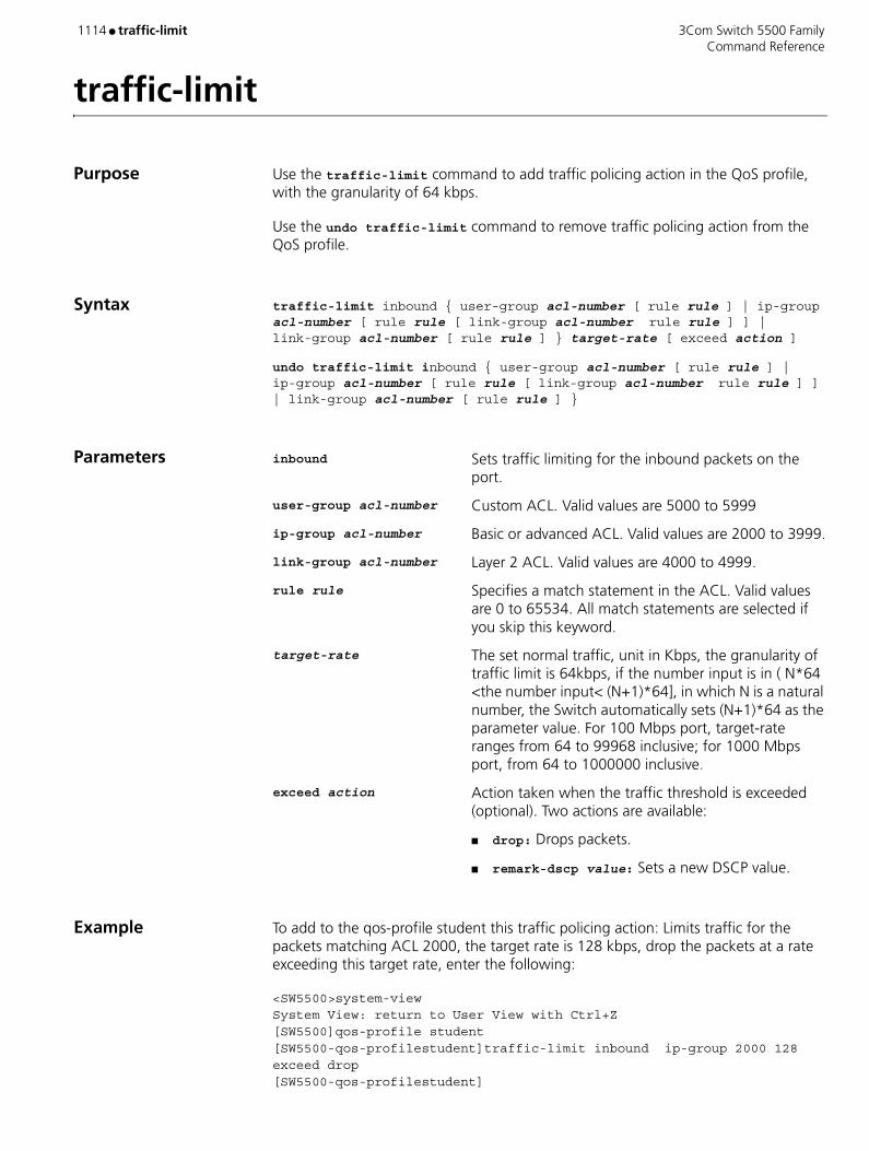
1114 ● traffic-limit 3Com Switch 5500 Family Command Reference
traffic-limit
Purpose Use the traffic-limit command to add traffic policing action in the QoS profile, with the granularity of 64 kbps.
Use the undo traffic-limit command to remove traffic policing action from the QoS profile.
Syntax traffic-limit inbound { user-group acl-number [ rule rule ] | ip-group acl-number [ rule rule [ link-group acl-number rule rule ] ] | link-group acl-number [ rule rule ] } target-rate [ exceed action ]
undo traffic-limit inbound { user-group acl-number [ rule rule ] | ip-group acl-number [ rule rule [ link-group acl-number rule rule ] ] | link-group acl-number [ rule rule ] }
Parameters inbound Sets traffic limiting for the inbound packets on the port.
user-group acl-number Custom ACL. Valid values are 5000 to 5999
ip-group acl-number Basic or advanced ACL. Valid values are 2000 to 3999.
link-group acl-number Layer 2 ACL. Valid values are 4000 to 4999.
rule rule Specifies a match statement in the ACL. Valid values are 0 to 65534. All match statements are selected if you skip this keyword.
target-rate The set normal traffic, unit in Kbps, the granularity of traffic limit is 64kbps, if the number input is in ( N*64 <the number input< (N+1)*64], in which N is a natural number, the Switch automatically sets (N+1)*64 as the parameter value. For 100 Mbps port, target-rate ranges from 64 to 99968 inclusive; for 1000 Mbps port, from 64 to 1000000 inclusive.
exceed action Action taken when the traffic threshold is exceeded (optional). Two actions are available:
■ drop: Drops packets.
■ remark-dscp value: Sets a new DSCP value.
Example To add to the qos-profile student this traffic policing action: Limits traffic for the packets matching ACL 2000, the target rate is 128 kbps, drop the packets at a rate exceeding this target rate, enter the following:
<SW5500>system-viewSystem View: return to User View with Ctrl+Z[SW5500]qos-profile student[SW5500-qos-profilestudent]traffic-limit inbound ip-group 2000 128 exceed drop[SW5500-qos-profilestudent]

3Com Switch 5500 Family traffic-limit ● 1115 Command Reference
View This command can be used in the following views:
■ QoS Profile view
Description You cannot remove traffic policing action from the specific QoS profile that has been applied to the port.
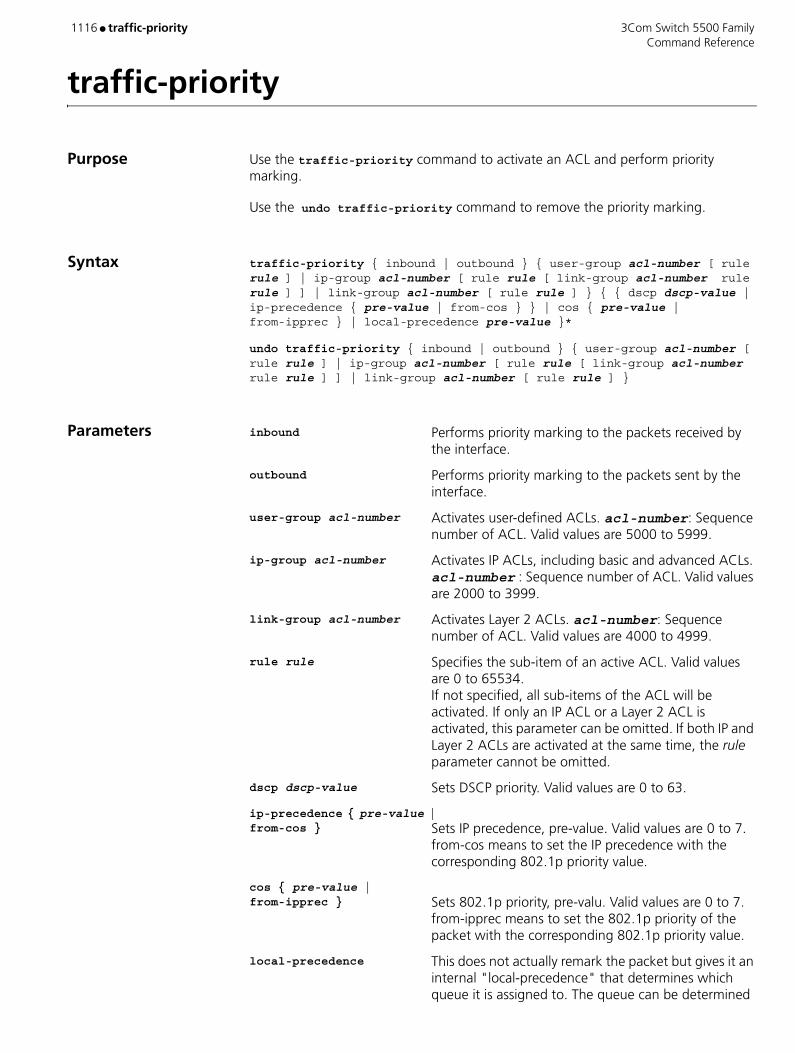
1116 ● traffic-priority 3Com Switch 5500 Family Command Reference
traffic-priority
Purpose Use the traffic-priority command to activate an ACL and perform priority marking.
Use the undo traffic-priority command to remove the priority marking.
Syntax traffic-priority { inbound | outbound } { user-group acl-number [ rule rule ] | ip-group acl-number [ rule rule [ link-group acl-number rule rule ] ] | link-group acl-number [ rule rule ] } { { dscp dscp-value | ip-precedence { pre-value | from-cos } } | cos { pre-value | from-ipprec } | local-precedence pre-value }*
undo traffic-priority { inbound | outbound } { user-group acl-number [ rule rule ] | ip-group acl-number [ rule rule [ link-group acl-number rule rule ] ] | link-group acl-number [ rule rule ] }
Parameters inbound Performs priority marking to the packets received by the interface.
outbound Performs priority marking to the packets sent by the interface.
user-group acl-number Activates user-defined ACLs. acl-number: Sequence number of ACL. Valid values are 5000 to 5999.
ip-group acl-number Activates IP ACLs, including basic and advanced ACLs. acl-number : Sequence number of ACL. Valid values are 2000 to 3999.
link-group acl-number Activates Layer 2 ACLs. acl-number: Sequence number of ACL. Valid values are 4000 to 4999.
rule rule Specifies the sub-item of an active ACL. Valid values are 0 to 65534. If not specified, all sub-items of the ACL will be activated. If only an IP ACL or a Layer 2 ACL is activated, this parameter can be omitted. If both IP and Layer 2 ACLs are activated at the same time, the rule parameter cannot be omitted.
dscp dscp-value Sets DSCP priority. Valid values are 0 to 63.
ip-precedence { pre-value | from-cos } Sets IP precedence, pre-value. Valid values are 0 to 7.
from-cos means to set the IP precedence with the corresponding 802.1p priority value.
cos { pre-value | from-ipprec } Sets 802.1p priority, pre-valu. Valid values are 0 to 7.
from-ipprec means to set the 802.1p priority of the packet with the corresponding 802.1p priority value.
local-precedence This does not actually remark the packet but gives it an internal "local-precedence" that determines which queue it is assigned to. The queue can be determined

3Com Switch 5500 Family traffic-priority ● 1117 Command Reference
by looking at cos-local precedence map using the display qos cos-local-precedence command.
Example Perform priority marking to packets that match with the permit rule of ACL 2000. Set its 802.1p priority to 0.
<SW5500>system-viewSystem View: return to User View with Ctrl+Z[SW5500]interface Ethernet 1/0/1[SW5500-Ethernet1/0/1]traffic-priority outbound ip-group 2000 cos 0[SW5500-Ethernet1/0/1]
View This command can be used in the following views:
■ Ethernet Port view
Description The system can mark the packets with various levels DSCP priority, IP Precedence, CoS (802.1p) priority and local Precedence.
Related Command display qos-interface traffic-priority

1118 ● traffic-priority 3Com Switch 5500 Family Command Reference
traffic-priority
Purpose Use the traffic-priority command to enable traffic priority marking for traffic that matches the ACL.
Use the undo traffic-priority command to remove traffic priority marking.
Syntax traffic-priority { inbound | outbound } { user-group acl-number [ rule rule ] | ip-group acl-number [ rule rule [ link-group acl-number rule rule ] ] | link-group acl-number [ rule rule ] } { { dscp dscp-value | ip-precedence { pre-value | from-cos } } | { pre-value | from-ipprec } | local-precedence pre-value }*
undo traffic-priority { inbound | outbound } { user-group acl-number [ rule rule ] | ip-group acl-number [ rule rule [ link-group acl-number rule rule ] ] | link-group acl-number [ rule rule ] }
Parameters inbound Replaces the preference value for the inbound packets on the port.
outbound Replaces the preference value for the outbound packets on the port.
user-group acl-number Custom ACL. Valid values are 5000 to 5999.
ip-group acl-number Basic or advanced ACL. Valid values are 2000 to 3999.
link-group acl-number Layer 2 ACL. Valid values are 4000 to 4999.
rule rule Specifies a match statement in the ACL. Valid values are 0 to 65534. All match statements are selected if you skip this keyword.
dscp dscp-value Sets DSCP preference value. Valid values are 0 to 63.
ip-precedence { pre-value | from-cos } Set IP precedence value, pre-value is in the range 0 to
7. from-cos sets the IP precedence value consistent with the 802.1p value.
cos { pre-value | from-ipprec } Sets the 802.1p value, pre-value is in the range 0 to 7.
from-ipprec sets the 802.1p value consistent with the IP precedence value.
local-precedence pre-valueSets local preference value. Valid values are 0 to 7.
Example To add to the student profile this preference replacing action: Sets local preference 0 to the inbound packets matching the ACL 2000, enter the following:
<SW5500>system-viewSystem View: return to User View with Ctrl+Z[SW5500]qos-profile student[SW5500-qos-profilestudent]traffic-priority inbound ip-group 2000 local-precedence 0[SW5500-qos-profilestudent]

3Com Switch 5500 Family traffic-priority ● 1119 Command Reference
View This command can be used in the following views:
■ QoS Profile view
Description You cannot remove traffic priority marking from the specific QoS profile that has been applied to the port.
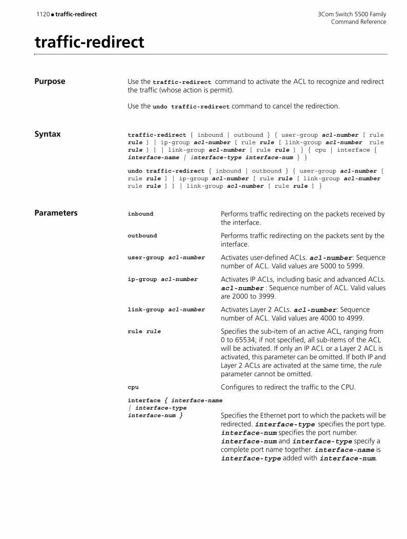
1120 ● traffic-redirect 3Com Switch 5500 Family Command Reference
traffic-redirect
Purpose Use the traffic-redirect command to activate the ACL to recognize and redirect the traffic (whose action is permit).
Use the undo traffic-redirect command to cancel the redirection.
Syntax traffic-redirect { inbound | outbound } { user-group acl-number [ rule rule ] | ip-group acl-number [ rule rule [ link-group acl-number rule rule ] ] | link-group acl-number [ rule rule ] } { cpu | interface { interface-name | interface-type interface-num } }
undo traffic-redirect { inbound | outbound } { user-group acl-number [ rule rule ] | ip-group acl-number [ rule rule [ link-group acl-number rule rule ] ] | link-group acl-number [ rule rule ] }
Parameters inbound Performs traffic redirecting on the packets received by the interface.
outbound Performs traffic redirecting on the packets sent by the interface.
user-group acl-number Activates user-defined ACLs. acl-number: Sequence number of ACL. Valid values are 5000 to 5999.
ip-group acl-number Activates IP ACLs, including basic and advanced ACLs. acl-number : Sequence number of ACL. Valid values are 2000 to 3999.
link-group acl-number Activates Layer 2 ACLs. acl-number: Sequence number of ACL. Valid values are 4000 to 4999.
rule rule Specifies the sub-item of an active ACL, ranging from 0 to 65534; if not specified, all sub-items of the ACL will be activated. If only an IP ACL or a Layer 2 ACL is activated, this parameter can be omitted. If both IP and Layer 2 ACLs are activated at the same time, the rule parameter cannot be omitted.
cpu Configures to redirect the traffic to the CPU.
interface { interface-name | interface-type interface-num } Specifies the Ethernet port to which the packets will be
redirected. interface-type specifies the port type. interface-num specifies the port number. interface-num and interface-type specify a complete port name together. interface-name is interface-type added with interface-num.

3Com Switch 5500 Family traffic-redirect ● 1121 Command Reference
Example Redirects the packets matching the ACL 2000 rules with action permit to the port Ethernet1/0/1.
<SW5500>system-viewSystem View: return to User View with Ctrl+Z[SW5500] interface Ethernet1/0/2[SW5500-Ethernet1/0/2] traffic-redirect inbound ip-group 2000 interface ethernet1/0/1[SW5500-Ethernet1/0/2]
View This command can be used in the following views:
■ Ethernet Port view
Description You can only redirect traffic within the same unit. That is to say that if you receive traffic on port 2/0/1 you can only redirect it to another port in unit 2.

1122 ● traffic-share-across-interface 3Com Switch 5500 Family Command Reference
traffic-share-across-interface
Purpose Use the traffic-share-across-interface command to enable traffic sharing across RIP interfaces to averagely distribute the traffic to the RIP interfaces of the router through equal-cost routes.
Use the undo traffic-share-across-interface command to disable traffic sharing.
Syntax traffic-share-across-interface
undo traffic-share-across-interface
Parameters None
Default By default, traffic sharing across RIP interfaces is disabled.
Example Enable traffic sharing across RIP interfaces.
<S5500> system-viewSystem View: return to User View with Ctrl+Z.[S5500] rip[S5500-rip] traffic-share-across-interface
View This command can be used in the following views:
■ RIP view

3Com Switch 5500 Family traffic-statistic ● 1123 Command Reference
traffic-statistic
Purpose Use the traffic-statistic command to activate the ACL to recognize and count the traffic (whose action is permit).
Use the undo traffic-statistic command to cancel the traffic statistics.
Syntax traffic-statistic inbound { user-group acl-number [ rule rule ] | ip-group acl-number [ rule rule [ link-group acl-number rule rule ] ] | link-group acl-number [ rule rule ] }
undo traffic-statistic inbound { user-group acl-number [ rule rule ] | ip-group acl-number [ rule rule [ link-group acl-number rule rule ] ] | link-group acl-number [ rule rule ] }
Parameters inbound Performs traffic statistic on the packets received by the interface.
user-group acl-number Activates user-defined ACLs. acl-number: Sequence number of ACL. Valid values are 5000 to 5999.
ip-group acl-number Activates IP ACLs, including basic and advanced ACLs. acl-number : Sequence number of ACL. Valid values are 2000 to 3999.
link-group acl-number Activates Layer 2 ACLs. acl-number: Sequence number of ACL. Valid values are 4000 to 4999.
rule rule Specifies the sub-item of an active ACL. Valid values are 0 to 65534. If not specified, all sub-items of the ACL will be activated. If only an IP ACL or a Layer 2 ACL is activated, this parameter can be omitted. If both IP and Layer 2 ACLs are activated at the same time, the rule parameter cannot be omitted.
Example Count the packets matching the ACL 2000 rules with action permit.
<SW5500>system-viewSystem View: return to User View with Ctrl+Z[SW5500]interface Ethernet 1/0/1[SW5500-Ethernet1/0/1]traffic-statistic inbound ip-group 2000[SW5500-Ethernet1/0/1]
View This command can be used in the following views:
■ System view
Description The statistics information of traffic-statistic command keeps track of the number of times a packet is matched to the ACL. You can use the display traffic-statistic command to display the statistics information.

1124 ● traffic-statistic 3Com Switch 5500 Family Command Reference
Related Command display qos-interface traffic-statistic

3Com Switch 5500 Family udp-helper enable ● 1125 Command Reference
udp-helper enable
Purpose Use the udp-helper enable command to enable the UDP Helper function.
Use the undo udp-helper enable command to disable the UDP Helper function.
Syntax udp-helper enable
undo udp-helper enable
Parameters None
Default By default, UDP Helper function is disabled.
Example To enable the UDP Helper function.
<SW5500>system-viewSystem View: return to User View with Ctrl+Z.[SW5500]udp-helper enable
View This command can be used in the following views:
■ System view
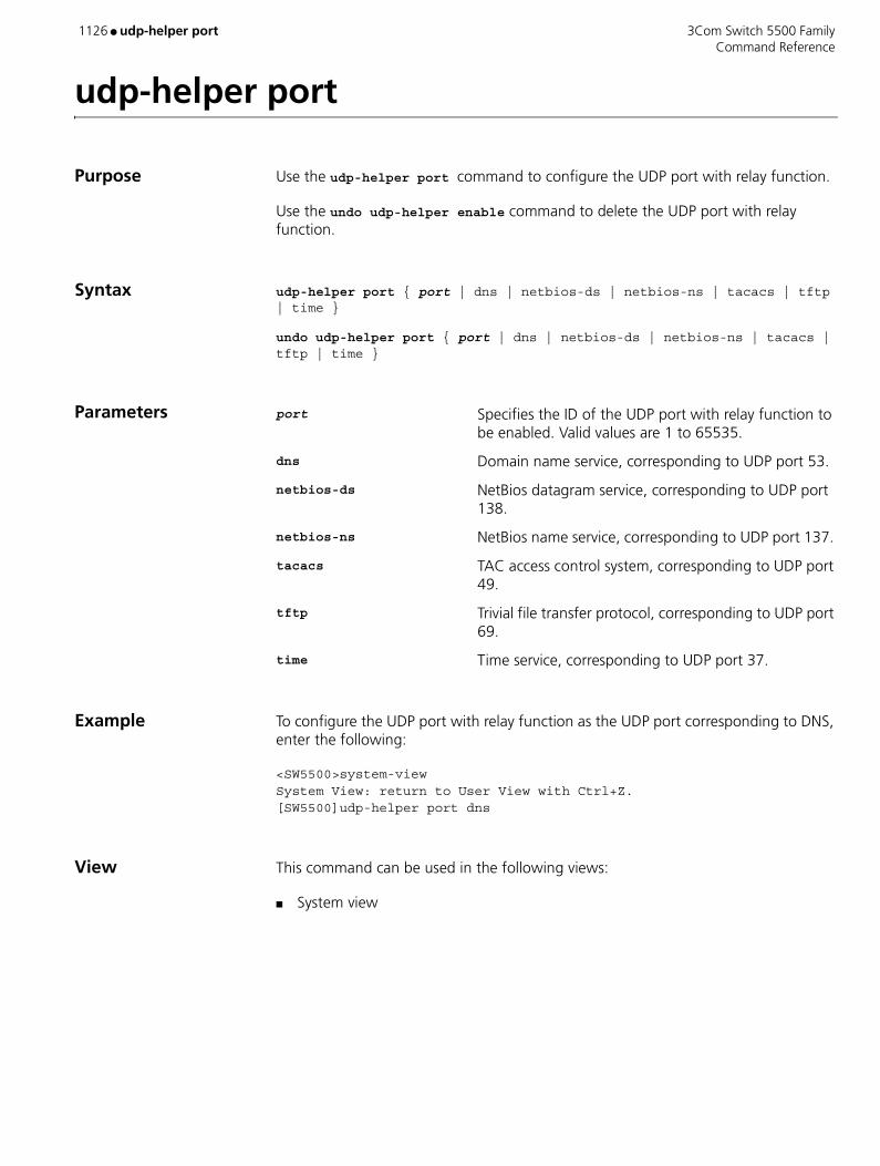
1126 ● udp-helper port 3Com Switch 5500 Family Command Reference
udp-helper port
Purpose Use the udp-helper port command to configure the UDP port with relay function.
Use the undo udp-helper enable command to delete the UDP port with relay function.
Syntax udp-helper port { port | dns | netbios-ds | netbios-ns | tacacs | tftp | time }
undo udp-helper port { port | dns | netbios-ds | netbios-ns | tacacs | tftp | time }
Parameters port Specifies the ID of the UDP port with relay function to be enabled. Valid values are 1 to 65535.
dns Domain name service, corresponding to UDP port 53.
netbios-ds NetBios datagram service, corresponding to UDP port 138.
netbios-ns NetBios name service, corresponding to UDP port 137.
tacacs TAC access control system, corresponding to UDP port 49.
tftp Trivial file transfer protocol, corresponding to UDP port 69.
time Time service, corresponding to UDP port 37.
Example To configure the UDP port with relay function as the UDP port corresponding to DNS, enter the following:
<SW5500>system-viewSystem View: return to User View with Ctrl+Z.[SW5500]udp-helper port dns
View This command can be used in the following views:
■ System view

3Com Switch 5500 Family udp-helper server ● 1127 Command Reference
udp-helper server
Purpose Use the udp-helper server command to configure the relay destination server.
Use the undo udp-helper server command to delete the relay destination server.
Syntax udp-helper server ip-address
undo udp-helper server [ ip-address ]
Parameters ip-address Specifies the IP address of the destination server.
Default By default, no relay destination server is configured.
Example To configure the relay destination server with IP address 192.1.1.2, enter the following:
<SW5500>system-viewSystem View: return to User View with Ctrl+Z.[SW5500]interface vlan-interface 1[SW5500-Vlan-interface1]udp-helper server 192.1.1.2
View This command can be used in the following views:
■ VLAN Interface view
Related Command display udp-helper server
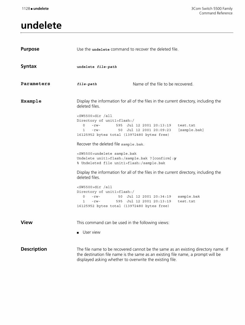
1128 ● undelete 3Com Switch 5500 Family Command Reference
undelete
Purpose Use the undelete command to recover the deleted file.
Syntax undelete file-path
Parameters file-path Name of the file to be recovered.
Example Display the information for all of the files in the current directory, including the deleted files.
<SW5500>dir /allDirectory of unit1>flash:/
0 -rw- 595 Jul 12 2001 20:13:19 test.txt1 -rw- 50 Jul 12 2001 20:09:23 [sample.bak]
16125952 bytes total (13972480 bytes free)
Recover the deleted file sample.bak.
<SW5500>undelete sample.bakUndelete unit1>flash:/sample.bak ?[confirm]:y% Undeleted file unit1>flash:/sample.bak
Display the information for all of the files in the current directory, including the deleted files.
<SW5500>dir /allDirectory of unit1>flash:/
0 -rw- 50 Jul 12 2001 20:34:19 sample.bak1 -rw- 595 Jul 12 2001 20:13:19 test.txt
16125952 bytes total (13972480 bytes free)
View This command can be used in the following views:
■ User view
Description The file name to be recovered cannot be the same as an existing directory name. If the destination file name is the same as an existing file name, a prompt will be displayed asking whether to overwrite the existing file.

3Com Switch 5500 Family undo snmp-agent ● 1129 Command Reference
undo snmp-agent
Purpose Use the undo snmp-agent command to disable all versions of SNMP running on the server.
Syntax undo snmp-agent
Parameters None
Example Disable the running SNMP agents of all SNMP versions.
<SW5500>system-viewSystem View: return to User View with Ctrl+Z.[SW5500]undo snmp-agent[SW5500]
View This command can be used in the following views:
■ System view
Description Any snmp-agent command will enable SNMP Agent.

1130 ● unicast-suppression 3Com Switch 5500 Family Command Reference
unicast-suppression
Purpose Use unicast-suppression to configure the amount of unicast traffic that will be accepted on a port.
Syntax unicast-suppression { ratio | pps pps }
undo unicast-suppression
Parameters ratio Specifies the bandwidth ratio of unicast traffic allowed on an Ethernet port. Valid ratio values are 1 to 100. The incremental step is 1. If not specified, the default ratio is 100, meaning that all unicast traffic is accepted. The smaller the ratio is, the less bandwidth is allocated to unicast traffic and therefore less broadcast traffic is accepted on the Ethernet port.
pps pps Specifies the maximum number of unicast packets per second accepted on an Ethernet port. Valid values are 1 to 148810 pps.
Example Enable a limit of 20% of the available bandwidth on a port to be allocated to unicast traffic. Unicast traffic exceeding 20% of the ports bandwidth will be discarded.
<SW5500>system-viewSystem View: return to User View with Ctrl+Z.[SW5500]interface ethernet 1/0/1[SW5500-Ethernet1/0/1]unicast-suppression 20[SW5500-Ethernet1/0/1]
Specify the maximum packets per second of the unicast traffic on an Ethernet1/0/1 as 1000 Mpps.
<SW5500>system-viewSystem View: return to User View with Ctrl+Z.[SW5500]interface ethernet 1/0/1[SW5500-Ethernet1/0/1]unicast-suppression pps 1000[SW5500-Ethernet1/0/1]
View This command can be used in the following views:
■ Ethernet Port view
Description Once the multicast traffic exceeds the value set by the user, the excess unicast traffic will be discarded. This feature can be used to ensure network service and prevent unicast storms.

3Com Switch 5500 Family update fabric ● 1131 Command Reference
update fabric
Purpose Use the update fabric command to update all the units in the fabric by using the App, BootROM, or Web file on a unit in the fabric.
Syntax update fabric file-name
Parameters file-name Name of the file used for the update.
Example Update all other units in the fabric by using the App file Switch 5500.app on this unit.
<5600-EI>display xm-fabricFabric name is 5600-EI, system mode is L3.Fabric authentication : no authentication, number of units in stack: 1.Unit Name Unit IDFirst 1(*) First 2First 8(*)<5600-EI >update fabric Switch 5500.app This will update the Fabric. Continue? [Y/N] y The software is verifying ... The result of verification is : Unit ID Free space(bytes) Enough Version comparison 1 2126848 Y Y 2 2125824 Y Y 8 1439744 Y Y warning: the verification is completed, start the file transmission [Y/N] y The fabric is being updated, 100% The Switch 5500.app is stored on unit 1 successfully The Switch 5500.app is stored on unit 2 successfully The Switch 5500.app is stored on unit 8 successfully Do you want to set Switch 5500.app to be running agent next time to boot[Y/N] yThe Switch 5500.app is configured successfully
View This command can be used in the following views:
■ User view
Description CAUTION: You can use the update fabric command only after inhibiting service traffic.
Currently, the system supports the global update of App, BootROM and Web file, and can distinguish the type of update file by the suffix of the file name. For example, SWITCH 5500.app, SWITCH 5500.btm, and SWITCH 5500.web can be used to update the host software, BootROM file, and Web file respectively.
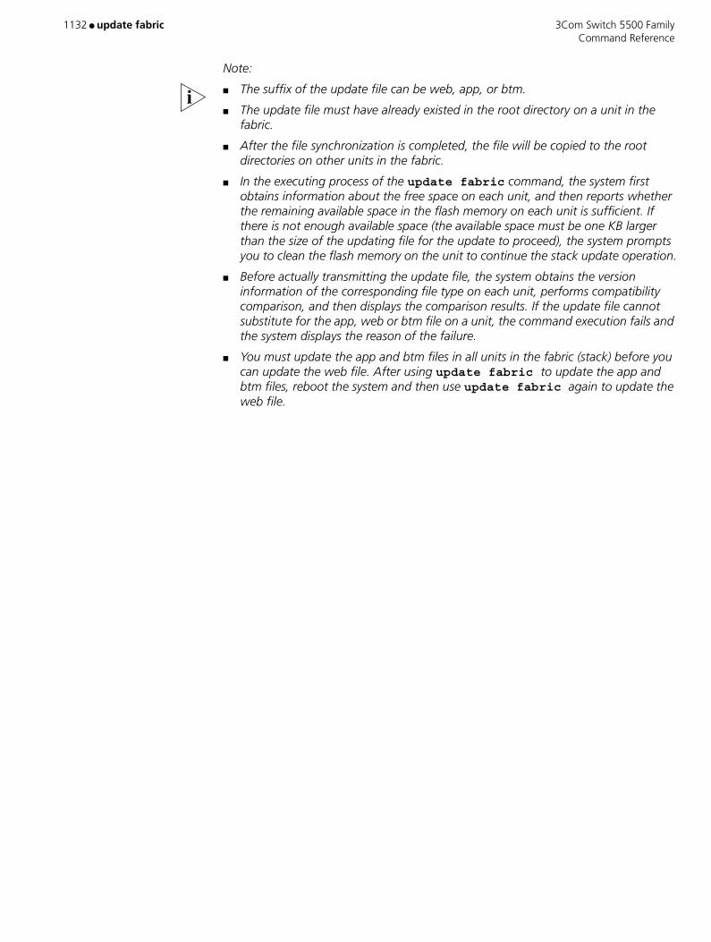
1132 ● update fabric 3Com Switch 5500 Family Command Reference
Note:
■ The suffix of the update file can be web, app, or btm.
■ The update file must have already existed in the root directory on a unit in the fabric.
■ After the file synchronization is completed, the file will be copied to the root directories on other units in the fabric.
■ In the executing process of the update fabric command, the system first obtains information about the free space on each unit, and then reports whether the remaining available space in the flash memory on each unit is sufficient. If there is not enough available space (the available space must be one KB larger than the size of the updating file for the update to proceed), the system prompts you to clean the flash memory on the unit to continue the stack update operation.
■ Before actually transmitting the update file, the system obtains the version information of the corresponding file type on each unit, performs compatibility comparison, and then displays the comparison results. If the update file cannot substitute for the app, web or btm file on a unit, the command execution fails and the system displays the reason of the failure.
■ You must update the app and btm files in all units in the fabric (stack) before you can update the web file. After using update fabric to update the app and btm files, reboot the system and then use update fabric again to update the web file.

3Com Switch 5500 Family user ● 1133 Command Reference
user
Purpose Use the user command to register an FTP user.
Syntax user username [ password ]
Parameters username Logon username.
password Logon password.
Example Log in the FTP Server with username tom and password hello.
<SW5500>ftp 1.1.1.1Trying ...Press CTRL+K to abortConnected.220 FTP service ready.User(none):hello331 Password required for hello.Password:230 User logged in[ftp]user tom hello331 Password required for tom.230 User logged in.[ftp]
View This command can be used in the following views:
■ FTP Client view
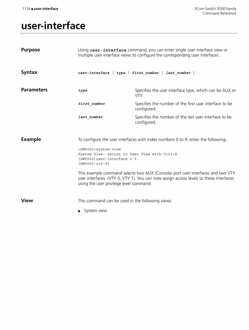
1134 ● user-interface 3Com Switch 5500 Family Command Reference
user-interface
Purpose Using user-interface command, you can enter single user interface view or multiple user interface views to configure the corresponding user interfaces.
Syntax user-interface [ type ] first_number [ last_number ]
Parameters type Specifies the user interface type, which can be AUX or VTY.
first_number Specifies the number of the first user interface to be configured.
last_number Specifies the number of the last user interface to be configured.
Example To configure the user interfaces with index numbers 0 to 9, enter the following:
<SW5500>system-viewSystem View: return to User View with Ctrl+Z.[SW5500]user-interface 0 9[SW5500-ui0-9]
This example command selects two AUX (Console) port user interfaces and two VTY user interfaces (VTY 0, VTY 1). You can now assign access levels to these interfaces using the user privilege level command.
View This command can be used in the following views:
■ System view

3Com Switch 5500 Family user-name-format ● 1135 Command Reference
user-name-format
Purpose Use the user-name-format command to set the username format acceptable to the TACACS server.
Syntax user-name-format { with-domain | without-domain }
Parameters with-domain Specifies that the domain name is taken along with the username that will be sent to the TACACS server
without-domain Specifies that no domain name is taken along with the username that will be sent to the TACACS server
Example Specify that no domain name is taken along with the username that will be sent out with the HWTACACS scheme 3Com.
[S5500-hwtacacs-3Com] user-name-format without-domain
View This command can be used in the following views:
■ HWTACACS view
Description For a HWTACACS scheme, each username sent to a TACACS server contains a domain name by default.
Username is usually in the “userid@isp-name” format, with the ISP domain name following “@”. The switch uses domain names to group users to different ISP domains. While some earlier TACACS servers do not accept the username with domain name. In this case, you must remove the domain name before sending a username to the server.
When you specify that no ISP domain name is contained in usernames for a HWTACACS scheme, this scheme cannot be used in two or more ISP domains at the same time; otherwise, errors may occur because the TACACS server considers users in different ISP domains but with the same name as one user.
Related Command hwtacacs scheme
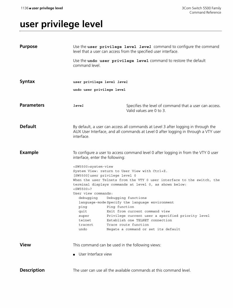
1136 ● user privilege level 3Com Switch 5500 Family Command Reference
user privilege level
Purpose Use the user privilege level level command to configure the command level that a user can access from the specified user interface.
Use the undo user privilege level command to restore the default command level.
Syntax user privilege level level
undo user privilege level
Parameters level Specifies the level of command that a user can access. Valid values are 0 to 3.
Default By default, a user can access all commands at Level 3 after logging in through the AUX User Interface, and all commands at Level 0 after logging in through a VTY user interface.
Example To configure a user to access command level 0 after logging in from the VTY 0 user interface, enter the following:
<SW5500>system-viewSystem View: return to User View with Ctrl+Z.[SW5500]user privilege level 0When the user Telnets from the VTY 0 user interface to the switch, the terminal displays commands at level 0, as shown below:<SW5500>?User view commands: debugging Debugging functions
language-mode Specify the language environmentping Ping function
quit Exit from current command view super Privilege current user a specified priority level telnet Establish one TELNET connection tracert Trace route function
undo Negate a command or set its default
View This command can be used in the following views:
■ User Interface view
Description The user can use all the available commands at this command level.
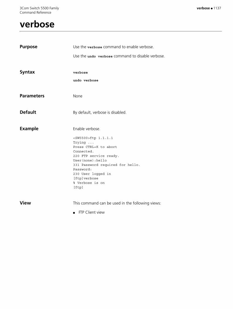
3Com Switch 5500 Family verbose ● 1137 Command Reference
verbose
Purpose Use the verbose command to enable verbose.
Use the undo verbose command to disable verbose.
Syntax verbose
undo verbose
Parameters None
Default By default, verbose is disabled.
Example Enable verbose.
<SW5500>ftp 1.1.1.1Trying ...Press CTRL+K to abortConnected.220 FTP service ready.User(none):hello331 Password required for hello.Password:230 User logged in[ftp]verbose% Verbose is on[ftp]
View This command can be used in the following views:
■ FTP Client view
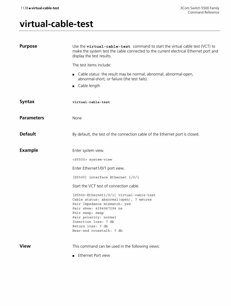
1138 ● virtual-cable-test 3Com Switch 5500 Family Command Reference
virtual-cable-test
Purpose Use the virtual-cable-test command to start the virtual cable test (VCT) to make the system test the cable connected to the current electrical Ethernet port and display the test results.
The test items include:
■ Cable status: the result may be normal, abnormal, abnormal-open, abnormal-short, or failure (the test fails).
■ Cable length
Syntax virtual-cable-test
Parameters None
Default By default, the test of the connection cable of the Ethernet port is closed.
Example Enter system view.
<S5500> system-view
Enter Ethernet1/0/1 port view.
[S5500] interface Ethernet 1/0/1
Start the VCT test of connection cable.
[S5500-Ethernet1/0/1] virtual-cable-testCable status: abnormal(open), 7 metresPair Impedance mismatch: yesPair skew: 4294967294 nsPair swap: swapPair polarity: normalInsertion loss: 7 dbReturn loss: 7 dbNear-end crosstalk: 7 db
View This command can be used in the following views:
■ Ethernet Port view
3Com Switch 5500 Family virtual-cable-test ● 1139 Command Reference
Description Note:
When the cable is in normal status, this command displays the total length of the cable.
When the cable is in abnormal status, this command displays the length from the current port to the abnormal position of the cable.
■ Pair Impedance mismatch
■ Pair skew
■ Pair swap
■ Pair polarity
■ Insertion loss
■ Return loss
■ Near-end crosstalk
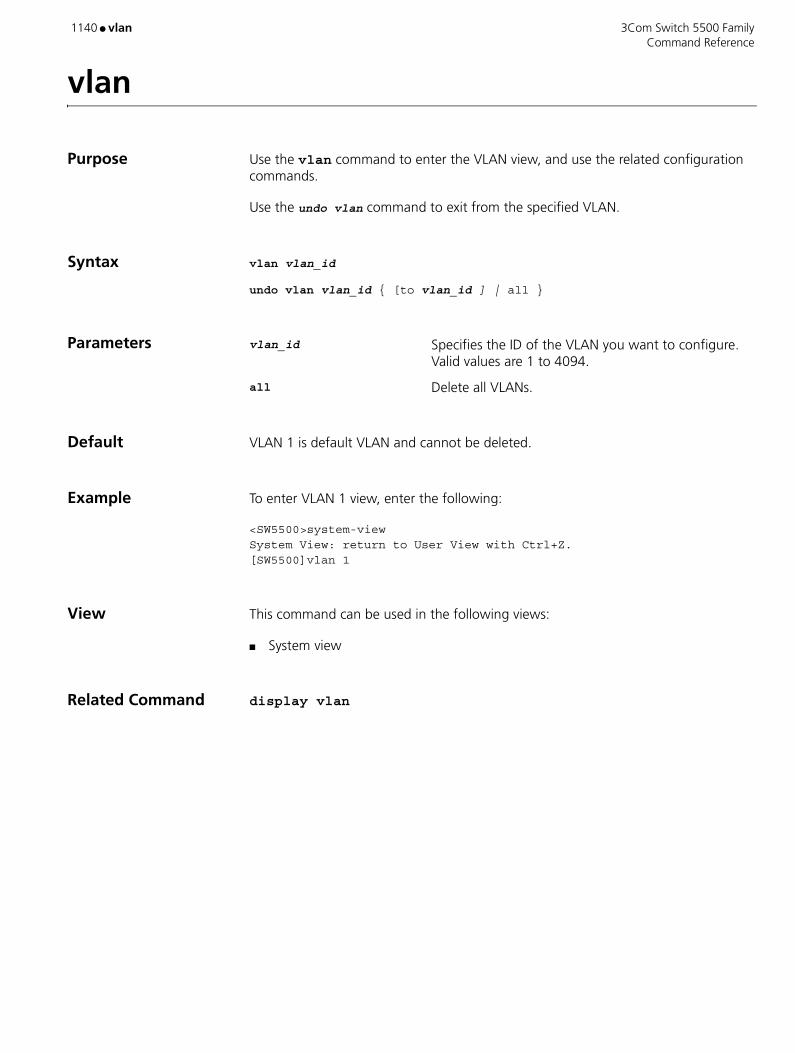
1140 ● vlan 3Com Switch 5500 Family Command Reference
vlan
Purpose Use the vlan command to enter the VLAN view, and use the related configuration commands.
Use the undo vlan command to exit from the specified VLAN.
Syntax vlan vlan_id
undo vlan vlan_id { [to vlan_id ] | all }
Parameters vlan_id Specifies the ID of the VLAN you want to configure. Valid values are 1 to 4094.
all Delete all VLANs.
Default VLAN 1 is default VLAN and cannot be deleted.
Example To enter VLAN 1 view, enter the following:
<SW5500>system-viewSystem View: return to User View with Ctrl+Z.[SW5500]vlan 1
View This command can be used in the following views:
■ System view
Related Command display vlan
3Com Switch 5500 Family vlan-assignment-mode ● 1141 Command Reference
vlan-assignment-mode
Purpose Use the vlan-assignment-mode command to configure the VLAN assignment mode.
Syntax vlan-assignment-mode { integer | string }
Parameters integer Sets the VLAN assignment mode to integer.
string Sets the VLAN assignment mode to string.
Default By default, the VLAN assignment mode is integer. That is, the switch supports the integer type of VLAN IDs assigned by RADIUS authentication server.
Example Set the VLAN assignment mode to string.
[S5500-isp-3Com163.net] vlan-assignment-mode string
View This command can be used in the following views:
■ ISP Domain view
Description Through dynamic VLAN assignment, the Ethernet switch dynamically adds the ports of the successfully authenticated users to different VLANs depending on the attribute values assigned by RADIUS server, so as to control the network resources the users can access.
In actual application, to cooperate with Guest VLAN, port control is usually set to the port-based mode. If it is set to the MAC address–based mode, each port can have only one user end connected.
Currently, the switch supports the following two data types of VLAN ID assigned by RADIUS authentication server:
■ Integer: The switch adds the port to a VLAN depending on the integer type of VLAN ID assigned by the RADIUS authentication server. If the VLAN does not exist, the switch creates the VLAN, and then adds the port to the new VLAN.
■ String: The switch compares the character string type of VLAN ID assigned by the RADIUS authentication server with the existing VLAN names on it. If the switch finds a match, it adds the port to the corresponding VLAN; otherwise the VLAN assignment fails and the user fails to pass the authentication.
Note: In string mode, the switch processes an assigned VLAN ID in this way: If the VLAN name assigned by the RADIUS server is a string that contains only digital characters (for example, 1024) and the string can be transformed to an integer number in the valid VLAN range, the switch transforms this string to an integer

1142 ● vlan-assignment-mode 3Com Switch 5500 Family Command Reference
number and adds the authenticated port to the VLAN whose ID is this number (VLAN 1024, for example).
Related Commands ■ dot1x guest-vlan
■ name

3Com Switch 5500 Family vlan-mapping modulo ● 1143 Command Reference
vlan-mapping modulo
Purpose Use the vlan-mapping modulo command to map VLANs to specific spanning tree instances.
Syntax vlan-mapping modulo modulo
Parameters modulo Specifies modulo value. Valid values are 1 to 16.
Default By default, all VLANs in a network are mapped to the CIST (spanning tree instance 0).
Example Map VLANs to spanning tree instances using the modulo of 16.
<S5500> system-view System View: return to User View with Ctrl+Z.[S5500] stp region-configuration [S5500-mst-region] vlan-mapping modulo 16
View This command can be used in the following views:
■ MST Region view
Description MSTP uses VLAN mapping tables to describe VLAN-to-spanning tree instance mappings. You can use this command to establish VLAN mapping tables and to map VLANs to specific spanning tree instances.
Note: A VLAN cannot be mapped to multiple spanning tree instances at a time. A VLAN-to-spanning tree instance mapping becomes invalid when you map the VLAN to another spanning tree instance.
You can map large amounts of VLANs to specific spanning tree instances quickly by using the vlan-mapping modulo modulo command. The ID of the spanning tree instance to which a VLAN is mapped can be figured out by using the following expression:
(VLAN ID-1) % modulo + 1
where (VLAN ID-1) % modulo yields the module of (VLAN ID-1) with regards to modulo. For example, if you set the modulo argument to 16, VLAN 1 is mapped to spanning tree instance 1, VLAN 2 is mapped to spanning tree instance 2, …, VLAN 16 is mapped to spanning tree instance 16, VLAN 17 is mapped to spanning tree instance 1, and so on.
Related Commands ■ active region-configuration
■ check region-configuration

1144 ● vlan-mapping modulo 3Com Switch 5500 Family Command Reference
■ region-name
■ revision-level

3Com Switch 5500 Family vlan to ● 1145 Command Reference
vlan to
Purpose Use the vlan to command to create multiple VLANs simultaneously.
Use the undo vlan to command to remove multiple VLANs simultaneously.
Syntax vlan { vlan-id1 to vlan-id2 | all }
undo vlan { vlan-id1 to vlan-id2 | all }
Parameters vlan-id1 Starts VLAN ID of the VLAN ID range. Valid values for this argument are from 1 to 4094.
to Identifies a VLAN ID range.
vlan-id2 Ends VLAN ID of the VLAN ID range. Valid values for this argument are from 1 to 4,094 and cannot be smaller than the vlan-id1 argument.
all Specifies to create all VLANs.
Example Create multiple VLANs with their VLAN IDs ranging from 4 through 100.
<S5500> system-viewSystem View: return to User View with Ctrl+Z.[S5500] vlan 4 to 100Please wait............. Done.
View This command can be used in the following views:
■ System view
Description Use the vlan to command to create multiple VLANs simultaneously.
Use the undo vlan to command to remove multiple VLANs simultaneously.
VLAN 1 is the default VLAN and cannot be removed.

1146 ● vlan-vpn enable 3Com Switch 5500 Family Command Reference
vlan-vpn enable
Purpose Use the vlan-vpn enable command to enable the VLAN-VPN function for a port.
Use the undo vlan-vpn command to disable the VLAN-VPN function for a port.
Syntax vlan-vpn enable
undo vlan-vpn
Parameters None
Default By default, the VLAN-VPN function is disabled.
Example Enable the VLAN-VPN function for Ethernet1/0/1 port.
<S5500> system-viewSystem View: return to User View with Ctrl+Z.[S5500]interface Ethernet 1/0/1[S5500-Ethernet1/0/1] vlan-vpn enable
View This command can be used in the following views:
■ Ethernet Port view
Description With the VLAN VPN function enabled, a received packet is tagged with the default VLAN tag of the receiving port no matter whether or not the packet already carries a VLAN tag. If the packet already carries a VLAN tag, the inserted VLAN tag becomes a nested VLAN tag in the packet. Otherwise, the packet is transmitted with the default VLAN tag of the port carried.
CAUTION: The VLAN-VPN function is unavailable if the port has any of the protocols among GVRP, GMRP, STP, IRF, NTDP and 802.1x enabled.

3Com Switch 5500 Family vlan-vpn inner-cos-trust ● 1147 Command Reference
vlan-vpn inner-cos-trust
Purpose Use the vlan-vpn inner-cos-trust enable command to enable the inner VLAN tag priority replication function.
Use the undo vlan-vpn inner-cos-trust command to disable the inner VLAN tag priority replication function.
Syntax vlan-vpn inner-cos-trust enable
undo vlan-vpn inner-cos-trust
Parameters None
Example Enable the inner VLAN tag priority replication function for Ethernet 1/0/2 port.
<S5500> system-viewSystem View: return to User View with Ctrl+Z.[S5500] interface Ethernet 1/0/2[S5500-Ethernet1/0/2] vlan-vpn inner-cos-trust enable
View This command can be used in the following views:
■ Ethernet Port view
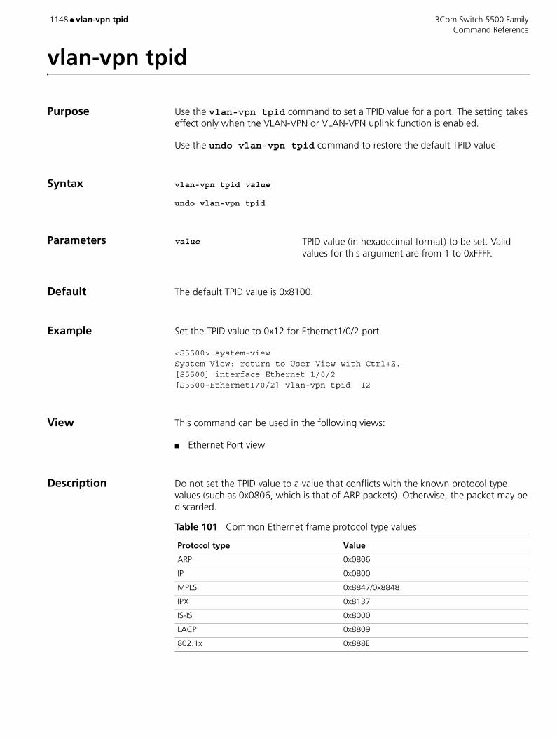
1148 ● vlan-vpn tpid 3Com Switch 5500 Family Command Reference
vlan-vpn tpid
Purpose Use the vlan-vpn tpid command to set a TPID value for a port. The setting takes effect only when the VLAN-VPN or VLAN-VPN uplink function is enabled.
Use the undo vlan-vpn tpid command to restore the default TPID value.
Syntax vlan-vpn tpid value
undo vlan-vpn tpid
Parameters value TPID value (in hexadecimal format) to be set. Valid values for this argument are from 1 to 0xFFFF.
Default The default TPID value is 0x8100.
Example Set the TPID value to 0x12 for Ethernet1/0/2 port.
<S5500> system-viewSystem View: return to User View with Ctrl+Z.[S5500] interface Ethernet 1/0/2[S5500-Ethernet1/0/2] vlan-vpn tpid 12
View This command can be used in the following views:
■ Ethernet Port view
Description Do not set the TPID value to a value that conflicts with the known protocol type values (such as 0x0806, which is that of ARP packets). Otherwise, the packet may be discarded.
Table 101 Common Ethernet frame protocol type values
Protocol type Value
ARP 0x0806
IP 0x0800
MPLS 0x8847/0x8848
IPX 0x8137
IS-IS 0x8000
LACP 0x8809
802.1x 0x888E
3Com Switch 5500 Family vlan-vpn tunnel ● 1149 Command Reference
vlan-vpn tunnel
Purpose Use the vlan-vpn tunnel command to enable the BPDU tunnel function.
Use the undo vlan-vpn tunnel command to disable the BPDU tunnel function.
Syntax vlan-vpn tunnel
undo vlan-vpn tunnel
Parameters None
Default By default, the BPDU tunnel function is disabled.
Example Enable the BPDU tunnel function for the switch.
<S5500> system-view System View: return to User View with Ctrl+Z.[S5500] vlan-vpn tunnel
■ Note:
■ You must enable STP on a device before enabling the BPDU tunnel function on it.
■ The BPDU tunnel function is only available to access ports.
■ To implement the BPDU tunnel function, the links between operator networks must be trunk links.
■ As the VLAN VPN function is unavailable to the ports with 802.1x, GVRP, GMRP, STP, or NTDP employed, the BPDU tunnel function is unavailable to these ports.
View This command can be used in the following views:
■ System view
Description The BPDU tunnel function enables BPDUs to be transparently transmitted between geographically dispersed user networks through specified VLAN VPNs in operator’s networks, allowing spanning trees to be generated across these user networks and keep independent of those of the operator’s networks.
1150 ● vlan-vpn uplink enable 3Com Switch 5500 Family Command Reference
vlan-vpn uplink enable
Purpose Use the vlan-vpn uplink enable command to configure a port to be a VLAN-VPN uplink port.
Use the undo vlan-vpn uplink command to remove the configuration.
Syntax vlan-vpn uplink enable
undo vlan-vpn uplink
Parameters None
Example Configure Ethernet1/0/2 port to be a VLAN-VPN uplink port.
<S5500> system-viewSystem View: return to User View with Ctrl+Z.[S5500]interface Ethernet 1/0/2[S5500-Ethernet1/0/2] vlan-vpn uplink enable VLAN-VPN uplink status: enabled
View This command can be used in the following views:
■ Ethernet Port view
Description When sending a VLAN-VPN packet, a VLAN-VPN uplink port replaces the TPID value in the outer VLAN tag of the packet with the customized TPID value. You can use the vlan-vpn tpid command to set the TPID value used by the VLAN-VPN uplink port.
CAUTION: The vlan-vpn uplink enable command and the vlan-vpn enable command are mutually exclusive. That is, if you execute the vlan-vpn
enable command on a port, you will fail to execute the vlan-vpn uplink
enable command on the same port. Similarly, if you execute the vlan-vpn
uplink enable command on a port, you will fail to execute the vlan-vpn
enable command on the same port

3Com Switch 5500 Family vlink-peer ● 1151 Command Reference
vlink-peer
Purpose Use the vlink-peer command to create and configure a virtual link.
Use the undo vlink-peer command to cancel an existing virtual link.
Use the authentication-mode command, when configuring virtual link authentication, to set the authentication type to MD5 cipher text or plain text on the backbone network.
Syntax vlink-peer router_id [ hello seconds | retransmit seconds | trans-delay seconds | dead seconds | simple password | md5 keyid key ]*
undo vlink-peer router-id
Parameters router_id Specifies the Router ID of a virtual link neighbor.
hello seconds Specifies the interval for the transmission of hello packets, in the range 1 to 8192 seconds. This must equal the hello seconds value of the router virtually linked to the interface. The default value is 10 seconds.
retransmit seconds Specifies the interval for the retransmission of LSA packets on an interface, in the range 1 to 8192 seconds. The default value is 5 seconds.
trans-delay seconds Specifies the delay interval for transmitting LSA packets on an interface, in the range 1 to 8192 seconds. The default value is 1 second.
dead seconds Specifies the dead time interval, in the range 1 to 8192 seconds. This value must equal the dead time of the virtually linked router, and must be at least four times that of the hello interval. The default value is 40 seconds.
simple password Specifies the simple text authentication key of the interface, in eight characters or less. This must equal the authentication key of the virtually linked neighbor.
md5 keyid Specifies the MD5 authentication key ID, in the range 1 to 255. This must be equal to the authentication key ID of the virtually linked peer.
key Specifies the MD5 authentication key. If it is input in a plain text form, the key is a character string not exceeding 16 characters. It will be displayed in a cipher text form in a length of 24 characters when display current-configuration command is executed. Inputting the MD5 key in a cipher text form with 24 characters is also supported.
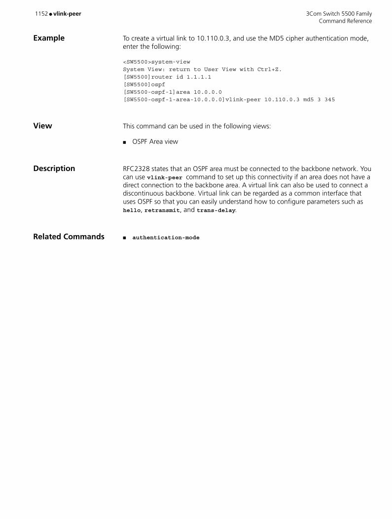
1152 ● vlink-peer 3Com Switch 5500 Family Command Reference
Example To create a virtual link to 10.110.0.3, and use the MD5 cipher authentication mode, enter the following:
<SW5500>system-viewSystem View: return to User View with Ctrl+Z.[SW5500]router id 1.1.1.1[SW5500]ospf[SW5500-ospf-1]area 10.0.0.0[SW5500-ospf-1-area-10.0.0.0]vlink-peer 10.110.0.3 md5 3 345
View This command can be used in the following views:
■ OSPF Area view
Description RFC2328 states that an OSPF area must be connected to the backbone network. You can use vlink-peer command to set up this connectivity if an area does not have a direct connection to the backbone area. A virtual link can also be used to connect a discontinuous backbone. Virtual link can be regarded as a common interface that uses OSPF so that you can easily understand how to configure parameters such as hello, retransmit, and trans-delay.
Related Commands ■ authentication-mode

3Com Switch 5500 Family voice-config ● 1153 Command Reference
voice-config
Purpose Use the voice-config command to configure option 184 and its sub-options, which will be sent to DHCP clients by a DHCP server as well when the DHCP server assigns IP addresses of a global address pool to DHCP clients.
Use the undo voice-config command to disable a DHCP server from sending option 184 and the specified sub-option to DHCP clients when the DHCP server assigns IP addresses to DHCP clients.
Syntax voice-config { ncp-ip ip-address | as-ip ip-address | voice-vlan vlan-id { disable | enable } | fail-over ip-address dialer-string }
undo voice-config [ ncp-ip | as-ip | voice-vlan | fail-over ]
Parameters ncp-ip Specifies the IP address of the NCP.
as-ip Specifies the IP address of the AS.
voice-vlan Specifies the voice VLAN.
fail-over Specifies the Fail-over call routing.
ip-address IP address of the NCP, alternate server, or Fail-over.
vlan-id ID of the voice VLAN. This argument ranges from 1 to 4094.
enable Enables the voice VLAN.
disable Disables the voice VLAN.
dialer-string Dial number string. This argument comprises of number 0 through 9 and the * character (acting as the wildcard).
Default By default, option 184 and its sub-options are not supported by a DHCP server.
Example Enter system view.
<S5500> system-viewSystem View: return to User View with Ctrl+Z.
Configure the DHCP server to support option 184 when the DHCP server assigns the IP addresses of address pool 123 (a global DHCP address pool) to DHCP clients, with the sub-options being set as follows:
NCP-IP: 1.1.1.1 AS-IP: 2.2.2.2 Voice VLAN: Enabled Voice VLAN ID: 1 IP address of Fail-over: 3.3.3.3 Dialer-string: 99*[S5500] dhcp select global all
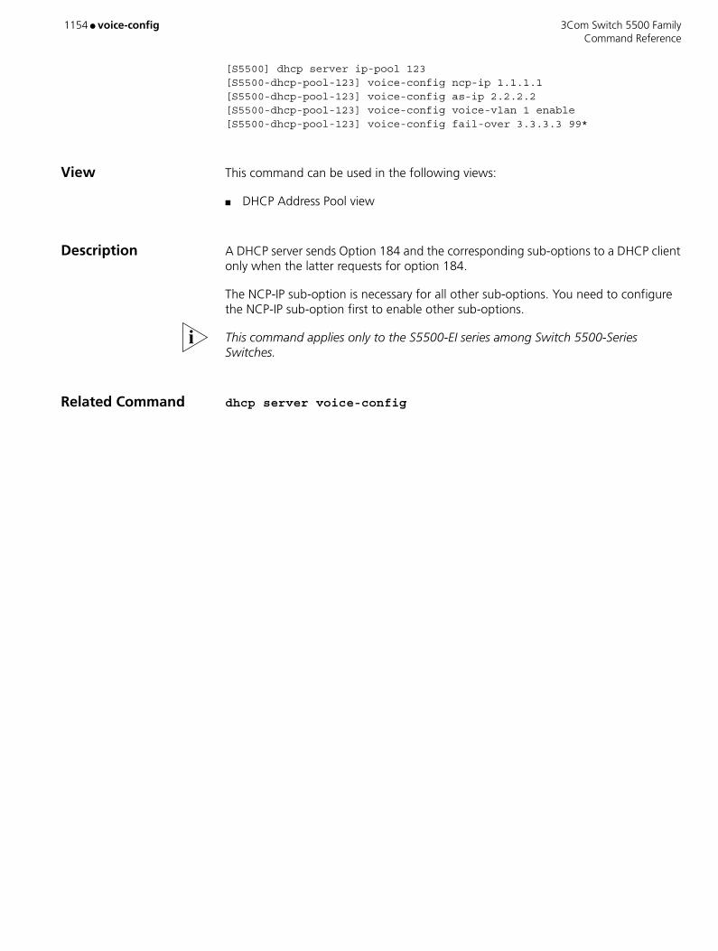
1154 ● voice-config 3Com Switch 5500 Family Command Reference
[S5500] dhcp server ip-pool 123[S5500-dhcp-pool-123] voice-config ncp-ip 1.1.1.1[S5500-dhcp-pool-123] voice-config as-ip 2.2.2.2[S5500-dhcp-pool-123] voice-config voice-vlan 1 enable[S5500-dhcp-pool-123] voice-config fail-over 3.3.3.3 99*
View This command can be used in the following views:
■ DHCP Address Pool view
Description A DHCP server sends Option 184 and the corresponding sub-options to a DHCP client only when the latter requests for option 184.
The NCP-IP sub-option is necessary for all other sub-options. You need to configure the NCP-IP sub-option first to enable other sub-options.
This command applies only to the S5500-EI series among Switch 5500-Series Switches.
Related Command dhcp server voice-config
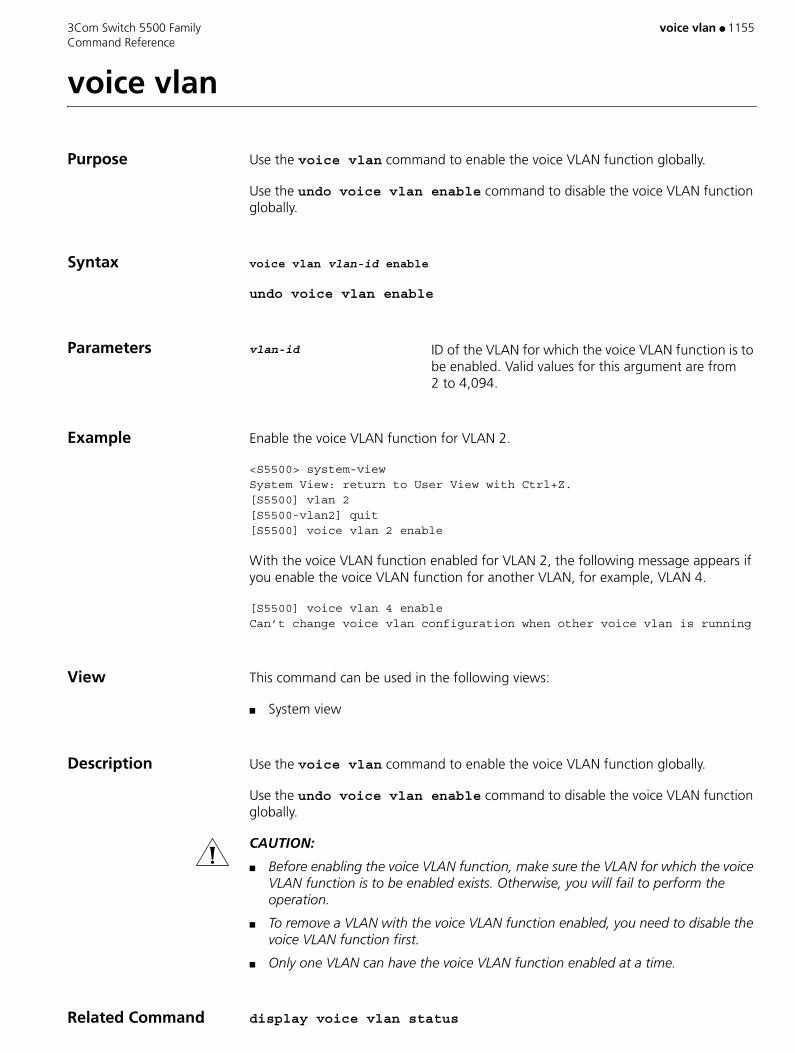
3Com Switch 5500 Family voice vlan ● 1155 Command Reference
voice vlan
Purpose Use the voice vlan command to enable the voice VLAN function globally.
Use the undo voice vlan enable command to disable the voice VLAN function globally.
Syntax voice vlan vlan-id enable
undo voice vlan enable
Parameters vlan-id ID of the VLAN for which the voice VLAN function is to be enabled. Valid values for this argument are from 2 to 4,094.
Example Enable the voice VLAN function for VLAN 2.
<S5500> system-viewSystem View: return to User View with Ctrl+Z.[S5500] vlan 2[S5500-vlan2] quit[S5500] voice vlan 2 enable
With the voice VLAN function enabled for VLAN 2, the following message appears if you enable the voice VLAN function for another VLAN, for example, VLAN 4.
[S5500] voice vlan 4 enableCan’t change voice vlan configuration when other voice vlan is running
View This command can be used in the following views:
■ System view
Description Use the voice vlan command to enable the voice VLAN function globally.
Use the undo voice vlan enable command to disable the voice VLAN function globally.
CAUTION:
■ Before enabling the voice VLAN function, make sure the VLAN for which the voice VLAN function is to be enabled exists. Otherwise, you will fail to perform the operation.
■ To remove a VLAN with the voice VLAN function enabled, you need to disable the voice VLAN function first.
■ Only one VLAN can have the voice VLAN function enabled at a time.
Related Command display voice vlan status

1156 ● voice vlan aging 3Com Switch 5500 Family Command Reference
voice vlan aging
Purpose Use the voice vlan aging command to set the aging time for a voice VLAN.
Use the undo voice vlan aging command to restore the default aging time for a voice VLAN.
Syntax voice vlan aging minutes
undo voice vlan aging
Parameters minutes Aging time (in minutes) to be set for a voice VLAN. Valid values for this argument are from 5 to 43,200. If not specified, the default is 1,440.
Example Set the aging time of the voice VLAN to 100 minutes.
<S5500> system-viewSystem View: return to User View with Ctrl+Z.[S5500] voice vlan aging 100
View This command can be used in the following views:
■ System view
Related Command display voice vlan status
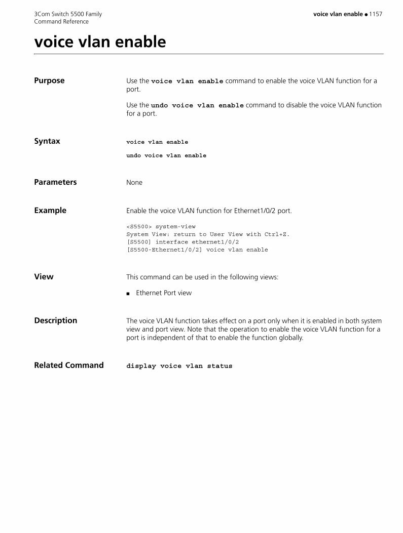
3Com Switch 5500 Family voice vlan enable ● 1157 Command Reference
voice vlan enable
Purpose Use the voice vlan enable command to enable the voice VLAN function for a port.
Use the undo voice vlan enable command to disable the voice VLAN function for a port.
Syntax voice vlan enable
undo voice vlan enable
Parameters None
Example Enable the voice VLAN function for Ethernet1/0/2 port.
<S5500> system-viewSystem View: return to User View with Ctrl+Z.[S5500] interface ethernet1/0/2[S5500-Ethernet1/0/2] voice vlan enable
View This command can be used in the following views:
■ Ethernet Port view
Description The voice VLAN function takes effect on a port only when it is enabled in both system view and port view. Note that the operation to enable the voice VLAN function for a port is independent of that to enable the function globally.
Related Command display voice vlan status

1158 ● voice vlan mode 3Com Switch 5500 Family Command Reference
voice vlan mode
Purpose Use the voice vlan mode auto command to configure an Ethernet port to operate in the automatic voice VLAN mode.
Use the undo voice vlan mode auto command to configure an Ethernet port to operate in the manual voice VLAN mode.
Syntax voice vlan mode auto
undo voice vlan mode auto
Parameters None
Default By default, an Ethernet port operates in the automatic voice VLAN mode.
Example Configure Ethernet 1/0/2 port to operate in the manual voice VLAN mode.
<S5500> system-viewSystem View: return to User View with Ctrl+Z.[S5500] interface ethernet 1/0/2[S5500-Ethernet1/0/2] undo voice vlan mode auto
View This command can be used in the following views:
■ Ethernet Port view
Description Use the voice vlan mode auto command to configure an Ethernet port to operate in the automatic voice VLAN mode.
Use the undo voice vlan mode auto command to configure an Ethernet port to operate in the manual voice VLAN mode.
These two commands are valid only before you enable the voice VLAN function globally.
Related Command display voice vlan status
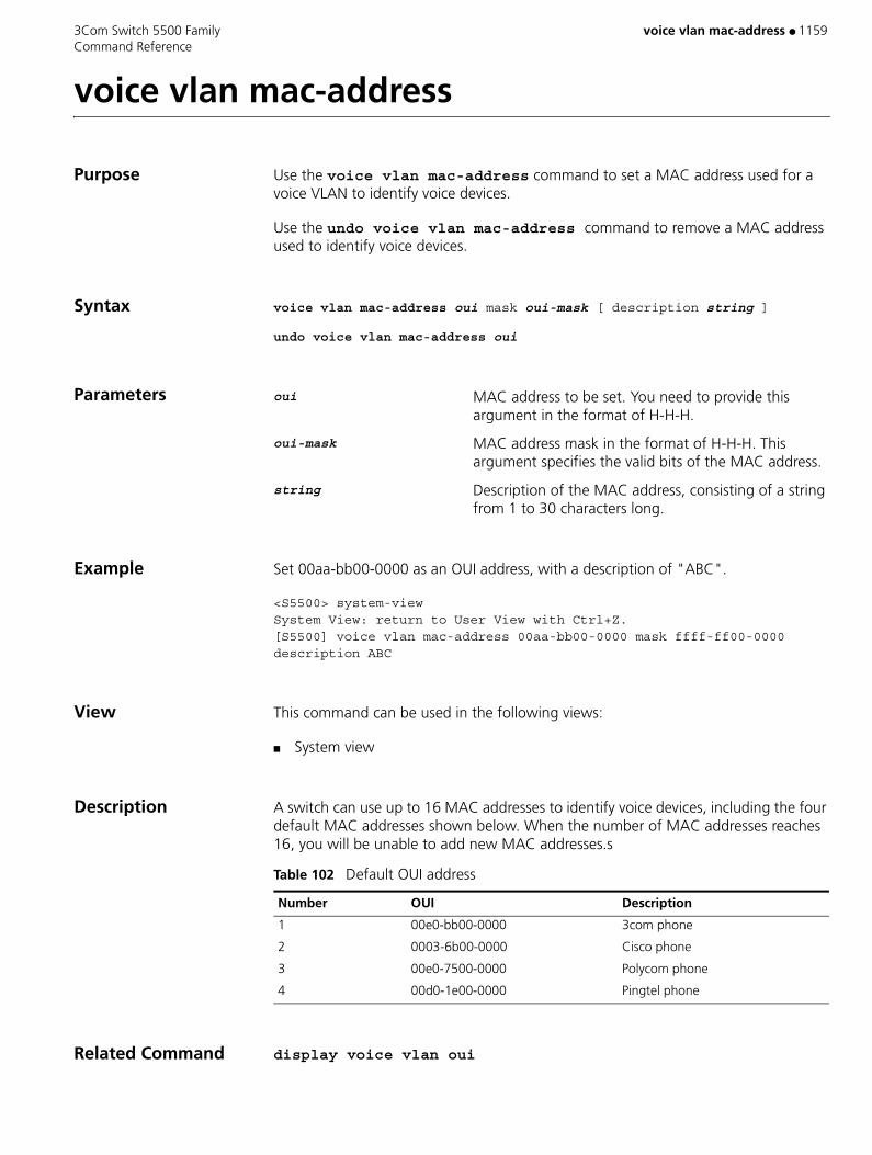
3Com Switch 5500 Family voice vlan mac-address ● 1159 Command Reference
voice vlan mac-address
Purpose Use the voice vlan mac-address command to set a MAC address used for a voice VLAN to identify voice devices.
Use the undo voice vlan mac-address command to remove a MAC address used to identify voice devices.
Syntax voice vlan mac-address oui mask oui-mask [ description string ]
undo voice vlan mac-address oui
Parameters oui MAC address to be set. You need to provide this argument in the format of H-H-H.
oui-mask MAC address mask in the format of H-H-H. This argument specifies the valid bits of the MAC address.
string Description of the MAC address, consisting of a string from 1 to 30 characters long.
Example Set 00aa-bb00-0000 as an OUI address, with a description of "ABC".
<S5500> system-viewSystem View: return to User View with Ctrl+Z.[S5500] voice vlan mac-address 00aa-bb00-0000 mask ffff-ff00-0000 description ABC
View This command can be used in the following views:
■ System view
Description A switch can use up to 16 MAC addresses to identify voice devices, including the four default MAC addresses shown below. When the number of MAC addresses reaches 16, you will be unable to add new MAC addresses.s
Related Command display voice vlan oui
Table 102 Default OUI address
Number OUI Description
1 00e0-bb00-0000 3com phone
2 0003-6b00-0000 Cisco phone
3 00e0-7500-0000 Polycom phone
4 00d0-1e00-0000 Pingtel phone
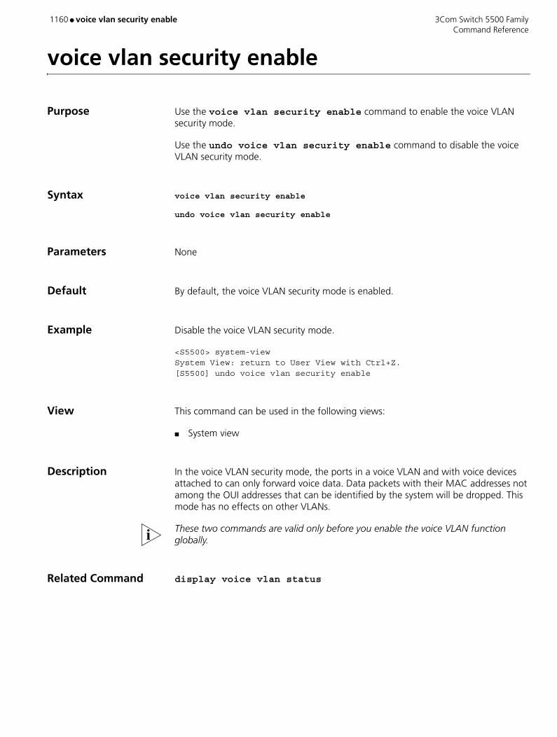
1160 ● voice vlan security enable 3Com Switch 5500 Family Command Reference
voice vlan security enable
Purpose Use the voice vlan security enable command to enable the voice VLAN security mode.
Use the undo voice vlan security enable command to disable the voice VLAN security mode.
Syntax voice vlan security enable
undo voice vlan security enable
Parameters None
Default By default, the voice VLAN security mode is enabled.
Example Disable the voice VLAN security mode.
<S5500> system-viewSystem View: return to User View with Ctrl+Z.[S5500] undo voice vlan security enable
View This command can be used in the following views:
■ System view
Description In the voice VLAN security mode, the ports in a voice VLAN and with voice devices attached to can only forward voice data. Data packets with their MAC addresses not among the OUI addresses that can be identified by the system will be dropped. This mode has no effects on other VLANs.
These two commands are valid only before you enable the voice VLAN function globally.
Related Command display voice vlan status

3Com Switch 5500 Family vrrp authentication-mode ● 1161 Command Reference
vrrp authentication-mode
Purpose Use the vrrp method command to map the MAC address of a backup group to the virtual router IP addresses.
You can map the real or virtual MAC address of a Layer 3 switch routing interface to virtual router IP addresses.
Use the undo vrrp method command to restore the default map settings.
Syntax vrrp authentication-mode authentication-type authentication-key
undo vrrp authentication-mode
Parameters authentication-type Authentication type, which can be:
■ simple; indicates to perform simple character authentication.
■ md5; indicates to perform the AH authentication with MD5 algorithm.
authentication-key Authentication key. When you specify authentication-type to be simple, you need to provide a string comprising up to eight characters. When you specify authentication-type to be md5, you need to provide a string comprising up to eight characters or a 24-character encrypted string.
Example Specify the authentication type and authentication key for a VRRP backup group.
<S5500> system-view System View: return to User View with Ctrl+Z.[S5500] interface vlan-interface 2[S5500-vlan-interface2] vrrp authentication-mode simple aabbcc
View This command can be used in the following views:
■ VLAN Interface view
Description If the simple or md5 authentication is configured, the authentication key is required.
This command sets the authentication type and authentication key for all the VRRP backup groups on an interface. As defined in the protocol, all the backup groups on an interface share the same authentication type and authentication key. And all the members joining the same backup group share the same authentication type and authentication key too.
The authentication key is case-sensitive.

1162 ● vrrp authentication-mode 3Com Switch 5500 Family Command Reference
The VRRP feature is supported by Switch 5500-EI series switches but is not supported by Switch 5500-SI series switches.

3Com Switch 5500 Family vrrp method ● 1163 Command Reference
vrrp method
Purpose Use the vrrp method command to map the MAC address of a backup group to the virtual router IP addresses.
You can map the real or virtual MAC address of a Layer 3 switch routing interface to virtual router IP addresses.
Use the undo vrrp method command to restore the default map settings.
Syntax vrrp method { real-mac | virtual-mac }
undo vrrp method
Parameters real-mac Maps the real MAC address of a Layer 3 switch routing interface to virtual router IP addresses.
virtual-mac Maps the virtual MAC address of a Layer 3 switch routing interface to virtual router IP addresses.
Default By default, the virtual MAC address of a backup group is mapped to the IP address of the virtual router.
If you map the virtual MAC address of a Layer 3 switch routing interface to virtual router IP addresses, you can create up to 14 backup groups on the VLAN interface.
Example Map the real MAC address of a routing interface to a virtual router IP address.
<S5500> system-view System View: return to User View with Ctrl+Z.[S5500] vrrp method real-mac
View This command can be used in the following views:
■ System view
Description Notes:
■ As the relationship between the MAC addresses of a backup group and a virtual router IP address cannot be configured after the backup group is created, configure the relationship before you create a backup group.
■ The VRRP feature is supported by Switch 5500-EI series switches but is not supported by Switch 5500-SI series switches.

1164 ● vrrp ping-enable 3Com Switch 5500 Family Command Reference
vrrp ping-enable
Purpose Use the vrrp ping-enable command to enable a backup group to respond to ping operations destined for its virtual router IP address.
Use the undo vrrp ping-enable command to revert to the default.
Syntax vrrp ping-enable
undo vrrp ping-enable
Parameters None
Default By default, a backup group does not respond to ping operations destined for its virtual router IP address.
As these two commands are invalid to switches in backup groups, use them before you create a backup group.
Example Enable a backup group to respond to ping operations destined for its virtual router IP address.
<S5500> system-view System View: return to User View with Ctrl+Z.[S5500] vrrp ping-enable
View This command can be used in the following views:
■ System view
Description Note: The VRRP feature is supported by Switch 5500-EI series switches but is not supported by Switch 5500-SI series switches.

3Com Switch 5500 Family vrrp vlan-interface vrid track ● 1165 Command Reference
vrrp vlan-interface vrid track
Purpose Use the vrrp vlan-Interface vrid track command to enable the port tracking function on the physical ports of a backup group.
Use the undo vrrp vlan-Interface vrid track command to disable the port tracking function.
Syntax vrrp vlan-interface vlan-id vrid virtual-router-ID track [ reduced value-reduced ]
undo vrrp vlan-interface vlan-id vrid virtual-router-ID track
Parameters virtual-router-ID VRRP backup group ID. Valid values are 1 to 255.
vlan-id VLAN ID.
value-reduced Value by which the priority of a switch is to decrease. Valid values for this argument are from 1 to 255. If not specified, the default is 10.
Example Configure that the priority of the switch decreases by 50 if its Ethernet1/0/1 port fails.
<S5500> system-view[S5500] vlan 2[S5500-vlan2] port Ethernet1/0/1[S5500-vlan2] quit[S5500] interface vlan-interface2[S5500-Vlan-interface2] vrrp vlan-interface 2 vrid 1 track reduced 50
View This command can be used in the following views:
■ VLAN Interface view
Description With the VRRP backup group port tracking function enabled, you can specify to track a specified port and decrease the priority of the switch when the port fails.
Using this function, you can enable the priority of a master switch to decrease by specific value when the uplink port of the master switch fails. This in turn triggers the new master to be determined in the backup group.
Notes:
■ The port to be tracked can be in the VLAN which the backup group belongs to.
■ Up to eight ports can be tracked simultaneously.
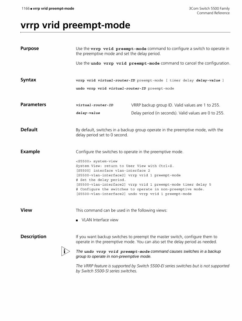
1166 ● vrrp vrid preempt-mode 3Com Switch 5500 Family Command Reference
vrrp vrid preempt-mode
Purpose Use the vrrp vrid preempt-mode command to configure a switch to operate in the preemptive mode and set the delay period.
Use the undo vrrp vrid preempt-mode command to cancel the configuration.
Syntax vrrp vrid virtual-router-ID preempt-mode [ timer delay delay-value ]
undo vrrp vrid virtual-router-ID preempt-mode
Parameters virtual-router-ID VRRP backup group ID. Valid values are 1 to 255.
delay-value Delay period (in seconds). Valid values are 0 to 255.
Default By default, switches in a backup group operate in the preemptive mode, with the delay period set to 0 second.
Example Configure the switches to operate in the preemptive mode.
<S5500> system-view System View: return to User View with Ctrl+Z.[S5500] interface vlan-interface 2[S5500-vlan-interface2] vrrp vrid 1 preempt-mode# Set the delay period.[S5500-vlan-interface2] vrrp vrid 1 preempt-mode timer delay 5# Configure the switches to operate in non-preemptive mode.[S5500-vlan-interface2] undo vrrp vrid 1 preempt-mode
View This command can be used in the following views:
■ VLAN Interface view
Description If you want backup switches to preempt the master switch, configure them to operate in the preemptive mode. You can also set the delay period as needed.
The undo vrrp vrid preempt-mode command causes switches in a backup group to operate in non-preemptive mode.
The VRRP feature is supported by Switch 5500-EI series switches but is not supported by Switch 5500-SI series switches.

3Com Switch 5500 Family vrrp vrid priority ● 1167 Command Reference
vrrp vrid priority
Purpose Use the vrrp vrid priority command to set the priority of a switch in a backup group.
Use the undo vrrp vrid priority command to revert to the default priority.
Syntax vrrp vrid virtual-router-ID priority priority
undo vrrp vrid virtual-router-ID priority
Parameters virtual-router-ID VRRP backup group ID. Valid values are 1 to 255.
priority Switch priority to be set. Valid values for this argument are 1 to 254. If not specified, the default is 100.
Example Set the priority to 120 for the switch in the backup group in VLAN 2 interface view.
<S5500> system-view System View: return to User View with Ctrl+Z.[S5500] interface vlan-interface 2[S5500-vlan-interface2] vrrp vrid 1 priority 120
View This command can be used in the following views:
■ VLAN Interface view
Description Switch priority determines the possibility for the switch to become a master switch. A switch with larger priority is more likely to become a master switch. Note that the priority of 0 is reserved for special use, and the priority of 255 is for IP address owners. That is, the priority of a switch that owns a virtual router IP address is fixed to 255 and cannot be modified.
The VRRP feature is supported by Switch 5500-EI series switches but is not supported by Switch 5500-SI series switches.

1168 ● vrrp vrid timer advertise 3Com Switch 5500 Family Command Reference
vrrp vrid timer advertise
Purpose Use the vrrp vrid timer advertise command to set the interval for the master switch of a backup group to send VRRP packets.
Use the undo vrrp vrid timer advertise command to revert to the default interval.
Syntax vrrp vrid virtual-router-ID timer advertise adver-interval
undo vrrp vrid virtual-router-ID timer advertise
Parameters virtual-router-ID VRRP backup group ID. Valid values are 1 to 255.
adver-interval Interval (in seconds) for the master switch of a backup group to send VRRP packets. Valid values for this argument are 1 to 255. If not specified, the default is 1.
Example Set the interval for the master switch to send VRRP packets to 15 seconds.
<S5500> system-view System View: return to User View with Ctrl+Z.[S5500] interface vlan-interface 2[S5500-vlan-interface2] vrrp vrid 1 timer advertise 15
View This command can be used in the following views:
■ VLAN Interface view
Description Note: Configuration error occurs if switches of the same backup group are configured with different adver-interval values.
As long as a switch in the backup group becomes the master switch, other switches, even if they are configured with a higher priority later, do not preempt the master switch unless they operate in the preemptive mode. The switch operating in preemptive mode will become the master switch when it finds its priority is higher than that of the current master switch, and the former master switch becomes a backup switch accordingly.
You can also set the delay period when configuring switches in a backup group to operate in the preemptive mode to enable a backup switch to undergo a specified period before it becomes the master switch. In an unstable network, backup switches may not receive packets from master switches in time because of network congestions. This causes master switches being determined frequently if the delay period is not configured or is too short. You can avoid this problem by setting the delay period to a proper value.
The VRRP feature is supported by Switch 5500-EI series switches but is not supported by Switch 5500-SI series switches.

3Com Switch 5500 Family vrrp vrid track ● 1169 Command Reference
vrrp vrid track
Purpose Use the vrrp vrid track command to set a VLAN interface to be tracked.
Use the undo vrrp vrid track command to disable a VLAN interface from being tracked.
Syntax vrrp vrid virtual-router-ID track vlan-interface valn-id [ reduced value-reduced ]
undo vrrp vrid virtual-router-ID track vlan-interface vlan-id [ reduced value-reduced ]
Parameters virtual-router-ID VRRP backup group ID. Valid values are 1 to 255.
vlan-interface vlan-id Specifies a VLAN interface ID.
value-reduced Value by which the priority is to decrease. Valid values for this argument are 1 to 255. If not specified, the default is 10.
Example Configure VLAN 2 interface to track VLAN 1 interface and specify the priority of the master switch of backup group 1 (on VLAN 2 interface) decreases by 50 when VLAN 1 interface goes down.
<S5500> system-view System View: return to User View with Ctrl+Z.[S5500] interface vlan-interface 2[S5500-vlan-interface2] vrrp vrid 1 track vlan-interface 1 reduced 50
View This command can be used in the following views:
■ VLAN Interface view
Description The VLAN interface tracking function extends the use of the backup function. With this function enabled, the backup function is applicable to the VLAN interface that belongs to a backup group and those that do not belong to a backup group. You can utilize the VLAN interface tracking function by specifying monitored VLAN interfaces.
With the VLAN interface tracking function enabled, the priority of a master switch decreases by the value set by the value-reduced argument when a tracked VLAN interface on the switch goes down. And other switches in the backup group, whose priorities are higher than the decreased priority of the master switch, may become the master switch.
Note:
■ Switches that own IP addresses do not support the VLAN interface tracking function.
■ A backup group can track up to eight VLAN interfaces simultaneously.

1170 ● vrrp vrid track 3Com Switch 5500 Family Command Reference
■ The VRRP feature is supported by Switch 5500-EI series switches but is not supported by Switch 5500-SI series switches.
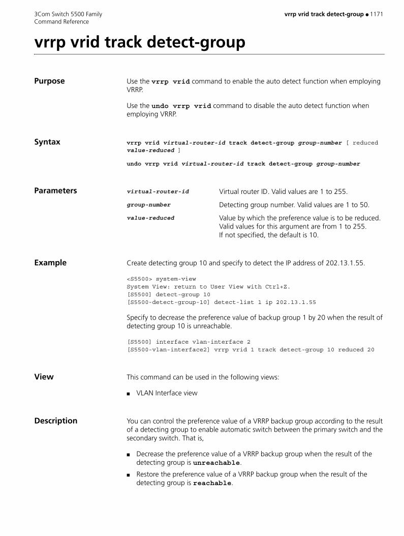
3Com Switch 5500 Family vrrp vrid track detect-group ● 1171 Command Reference
vrrp vrid track detect-group
Purpose Use the vrrp vrid command to enable the auto detect function when employing VRRP.
Use the undo vrrp vrid command to disable the auto detect function when employing VRRP.
Syntax vrrp vrid virtual-router-id track detect-group group-number [ reduced value-reduced ]
undo vrrp vrid virtual-router-id track detect-group group-number
Parameters virtual-router-id Virtual router ID. Valid values are 1 to 255.
group-number Detecting group number. Valid values are 1 to 50.
value-reduced Value by which the preference value is to be reduced. Valid values for this argument are from 1 to 255. If not specified, the default is 10.
Example Create detecting group 10 and specify to detect the IP address of 202.13.1.55.
<S5500> system-viewSystem View: return to User View with Ctrl+Z.[S5500] detect-group 10[S5500-detect-group-10] detect-list 1 ip 202.13.1.55
Specify to decrease the preference value of backup group 1 by 20 when the result of detecting group 10 is unreachable.
[S5500] interface vlan-interface 2[S5500-vlan-interface2] vrrp vrid 1 track detect-group 10 reduced 20
View This command can be used in the following views:
■ VLAN Interface view
Description You can control the preference value of a VRRP backup group according to the result of a detecting group to enable automatic switch between the primary switch and the secondary switch. That is,
■ Decrease the preference value of a VRRP backup group when the result of the detecting group is unreachable.
■ Restore the preference value of a VRRP backup group when the result of the detecting group is reachable.

1172 ● vrrp vrid virtual-ip 3Com Switch 5500 Family Command Reference
vrrp vrid virtual-ip
Purpose Use the vrrp vrid virtual-ip command to add a virtual router IP address to an existing backup group.
Use the undo vrrp vrid virtual-ip command to remove a virtual router IP address from an existing backup group.
Syntax vrrp vrid virtual-router-ID virtual-ip virtual-address
undo vrrp vrid virtual-router-ID virtual-ip virtual-address
Parameters virtual-router-ID VRRP backup group ID. Valid values are 1 to 255.
virtual-address Virtual router IP address to be configured.
Example Create a backup group.
<S5500> system-view System View: return to User View with Ctrl+Z.[S5500] interface vlan-interface 2[S5500-vlan-interface2] vrrp vrid 1 virtual-ip 10.10.10.10# Add a virtual router IP address to an existing backup group.[S5500-vlan-interface2] vrrp vrid 1 virtual-ip 10.10.10.11# Remove a virtual router IP address from a backup group.[S5500-vlan-interface2] undo vrrp vrid 1 virtual-ip 10.10.10.10# Remove a backup group.[S5500-vlan-interface2] undo vrrp vrid 1
View This command can be used in the following views:
■ VLAN Interface view
Description The vrrp vrid virtual-ip command can also be used to create a backup group. You can add up to 16 virtual router IP addresses to a backup group. The undo vrrp vrid virtual-ip command can also be used to remove an existing backup group. A backup group is removed if all the virtual router IP addresses configured for it are removed.
The VRRP feature is supported by Switch 5500-EI series switches but is not supported by Switch 5500-SI series switches.

3Com Switch 5500 Family wred ● 1173 Command Reference
wred
Purpose Use the wred command to configure WRED parameters. WRED (Weighted Random Early Detection) is a qeueing feature used in a network to mitigate the effects of queue congestion.
Use the undo wred command to restore the default settings.
Syntax wred queue-index qstart probability
undo wred queue-index
Parameters queue-index Index of output queue. Valid values are 0 to 7.
qstart Start random discarding queue length, if the queue is shorter than the value, no packet will be dropped. Valid values are 1 to 128. The value must be a multiple of 16 KBytes.
probability Discarding probability.
Default By default, the wred function is disabled.
Example To configure ‘start random discarding queue length’ of queue 0 is 32kbytes, discarding probability is 50%, enter the following:
<SW5500>system-viewSystem View: return to User View with Ctrl+Z[SW5500]interface Ethernet 1/0/1[SW5500-Ethernet1/0/1]wred 0 32 50[SW5500-Ethernet1/0/1]
View This command can be used in the following views:
■ Ethernet Port view
1174 ● xmodem 3Com Switch 5500 Family Command Reference
xmodem
Purpose Use the xmodem command to establish an xmodem connection.
Syntax xmodem get filename
Parameters get Obtain remote data file.
filename Specifies the filename to retrieve.
Example <5500-EI>xmodem
View This command can be used in the following views:
■ User view
Description Xmodem is a protocol for transferring files during direct dial-up communications. Xmodem has basic error checking to ensure that information isn’t lost or corrupted during transfer; it sends data in 128-byte blocks.
3Com Switch 5500 Family xrn-fabric authentication-mode ● 1175 Command Reference
xrn-fabric authentication-mode
Purpose Use the xrn-fabric authentication-mode command to configure or delete the authentication mode of the fabric.
Syntax xrn-fabric authentication-mode { simple password | md5 key }
undo xrn-fabric authentication-mode
Parameters password Password, consisting of a character string from 1 to 16 characters long.
key Key word, consisting of a character string from 1 to 16 characters long.
Default By default, no authentication mode is configured on the Fabric.
Example To set the authentication mode of the Fabric to simple, with the password "hello", enter the following:
<SW5500>system-viewSystem View: return to User View with Ctrl+Z.[SW5500]xrn-fabric authentication-mode simple hello
View This command can be used in the following views:
■ System view
Description CAUTION: All units must have the same Fabric authentication settings in order to form a stack of units.

1176 ● xrn-fabric authentication-mode 3Com Switch 5500 Family Command Reference

3Com Switch 5500 Family ● 1177 Command Reference
COMMANDS BY FUNCTION
Numerics
802.1xdot1x guest-vlan 504dot1x retry-version-max 513dot1x supp-proxy-check 514dot1x timer ver-period 518dot1x version-check 519
A
AAA and Radiusaccess-limit 29accounting 30accounting optional 35accounting-on enable 33attribute 63authentication 65authorization 69cut connection 113display connection 226display domain 259display dot1x 260display local-server statistics 321display local-user 322display radius 415display radius statistics 416domain 496dot1x 499dot1x authentication-method 501, 502dot1x dhcp-launch 503dot1x max-user 506dot1x port-control 507dot1x port-method 509dot1x quiet-period 511dot1x retry 512dot1x timer 516level 650local-server 654messenger 684name 705radius nas-ip 842radius scheme 844radius-scheme 843reset dot1x statistics 864reset radius statistics 886retry realtime-accounting 902retry stop-accounting 903scheme 940self-service-url 946server-type 948service-type 951state 1010, 1011

1178 ● 3Com Switch 5500 Family Command Reference
stop-accounting-buffer enable 1022vlan-assignment-mode 1141
Address Managementam enable 43am ip-pool 44am user-bind 47display am 208display am user-bind 209
Auto-detectdetect-group 166detect-list 167display detect-group 237ip route-static 642option 737retry 901standby detect-group 1009timer loop 1103timer wait 1108
C
Centralized MACdebugging mac-authentication event 135display mac-authentication 331mac-authentication 671mac-authentication authpassword 674mac-authentication authusername 675mac-authentication domain 676mac-authentication mode 673mac-authentication timer 677
Cluster Configurationadd-member 40administrator-address 42auto-build 70build 84cluster 101cluster enable 102cluster switch-to 105cluster-mac 103cluster-mac syn-interval 104delete-member 161display cluster 219display cluster candidates 221display cluster members 223ftp cluster 547ftp-server 552holdtime 572ip-pool 641logging-host 658management-vlan 678nm-interface vlan-interface 714port-tagged 816reboot member 847snmp-host 988

3Com Switch 5500 Family ● 1179 Command Reference
tftp cluster get 1090tftp cluster put 1091tftp-server 1094timer 1102
D
Device Managementdisplay device 238
DHCPaccounting domain 32address-check 41debugging dhcp server 124debugging dhcp-relay 122dhcp enable 168dhcp relay information enable 169dhcp relay information strategy 170dhcp select global 171dhcp server detect 176dhcp server dns-list 177dhcp server domain-name 179dhcp server expired 181dhcp server forbidden-ip 183dhcp server ip-pool 186dhcp server nbns-list 187dhcp server netbios-type 189dhcp server option 191dhcp server ping 193dhcp server static-bind 194dhcp server voice-config 195dhcp server voice-config interface 197dhcp-security static 199dhcp-security tracker 200dhcp-server 175dhcp-server ip 185dhcp-snooping 201dhcp-snooping trust 202display dhcp server conflict 243display dhcp server expired 244display dhcp server free-ip 246display dhcp server ip-in-use 248display dhcp server statistics 250display dhcp server tree 252display dhcp-security 240display dhcp-server 241display dhcp-server intervace vlan-interface 247display dhcp-snooping 254display dhcp-snooping trust 255dns-list 495domain-name 498expired 525gateway-list 562hcp select interface 173nbns-list 707netbios-type 711network 712reset dhcp server conflict 861reset dhcp server ip-in-use 862

1180 ● 3Com Switch 5500 Family Command Reference
reset dhcp server statistics 863static-bind ip-address 1013static-bind mac-address 1015voice-config 1153
DLDPdebugging DLDP 128display dldp 257dldp 488dldp authentication-mode 490dldp interval 491dldp reset 492dldp unidirectional-shutdown 493dldp work-mode 494
E
EADsecurity-policy-server 945
F
Fabricchange self-unit 91change unit-id 92display xrn-fabric 487ftm stacking-vlan 545set unit name 955sysname 1073xrn-fabric authentication-mode 1175
File Management Systembackup current-configuration to 72boot attribute-switch 75update fabric 1131
File System Managementboot boot-loader 76boot boot-loader backup-attribute 77boot web-packege 79display boot-loader 213display current-configuration 229display saved-configuration 436display startup 456display this 468ftp 546ftp server enable 553get 563local-user 655local-user password-display mode 656reset recycle-bin 887reset saved-configuration 888restore startup-configuration from 900save 934startup bootrom-access enable 1019startup saved-configuration 1020
3Com Switch 5500 Family ● 1181 Command Reference
G
Gratuitous ARPgratuitous-arp learning enable 564
GVRPdisplay garp statistics 275display garp timer 276display gvrp statistics 277display gvrp status 278garp timer 559garp timer leaveall 561gvrp 565gvrp registration 566reset garp statistics 865
H
HWTACACSdata-flow-format 115debugging hwtacacs 129display hwtacacs 280display stop-accounting buffer 457hwtacacs nas-ip 574hwtacacs scheme 575key 644nas-ip 706primary accounting 821primary authentication 822primary authorization 823reset hwtacacs statistics 866reset stop-accounting-buffer 890secondary accounting 942secondary authentication 943secondary authorization 944timer quiet 1104timer realtime-accounting 1105timer response-timeout 1106user-name-format 1135
I
IGMPdisplay mac-address multicast static 330display multicast-souce-deny 349mac-address multicast interface vlan 668mac-address multicast vlan 669
Information Centerdisplay logbuffer 324display trapbuffer 471info-center synchronous 625info-center timestamp loghost 627
IRFdisplay ftm 270display rmon history unit 428

1182 ● 3Com Switch 5500 Family Command Reference
display rmon statistics unit 432fabric port enable 526
L
Loopback Detectiondisplay-loopback-detection 326
M
Management VLANdisplay bootp client 214
Miscellaneousdisplay bootp client 214display drv 262display mpm 339fixdisk 538free web-users 543icmp 576pki 786xmodem 1174
MSDPcache-sa-enable 86debugging msdp 136display msdp brief 340display msdp peer-status 341display msdp sa-cache 342display msdp sa-count 344import-source 609msdp 697msdp-tracert 698originating-rp 738peer connect-interface 767peer description 768peer mesh-group 769peer minimum-ttl 770peer request-sa-enable 772peer sa-cache-maximum 773peer sa-policy 774peer sa-request-policy 775reset msdp peer 872reset msdp sa-cache 873reset msdp statistics 874shutdown 963timer retry 1107
MSTPactive region-configuration 39check region-configuration 93display stp 458display stp region-configuration 461instance 629region-name 848reset stp 891revision-level 905stp 1024
3Com Switch 5500 Family ● 1183 Command Reference
stp bpdu-protection 1025stp bridge-diameter 1026stp cost 1027stp edged-port 1028stp interface 1031stp interface cost 1032stp interface edged-port 1034stp interface loop protection 1036stp interface mcheck 1037stp interface point-to-point 1038stp interface port priority 1040stp interface root-protection 1041stp interface transmit-limit 1043stp loop-protection 1044stp max-hops 1045stp mcheck 1046stp mode 1047stp pathcost-standard 1048stp point-to-point 1050stp port priority 1052stp priority 1053stp region-configuration 1054stp root primary 1055stp root secondary 1058stp root-protection 1057stp tc-protection 1060stp timer forward-delay 1063stp timer hello 1065stp timer max-age 1066stp timer-factor 1062stp transmit-limit 1067vlan-mapping modulo 1143vlan-vpn tunnel 1149
Multicast Protocolbsr-policy 82c-bsr 87c-rp 88crp-policy 111debugging igmp 130debugging multicast forwarding 137debugging multicast kernel-routing 138debugging multicast status-forwarding 139debugging pim common 141debugging pim dm 142debugging pim sm 143display igmp group 283display igmp interface 284display igmp-snooping configuration 285display igmp-snooping group 286display igmp-snooping statistics 287display mac-address multicast static 330display multicast forwarding-table 345display multicast routing-table 347display multicast-source-deny 349display pim bsr-info 385display pim interface 386display pim neighbor 387display pim routing-table 388

1184 ● 3Com Switch 5500 Family Command Reference
display pim rp-info 390igmp enable 584igmp group-limit 585igmp group-policy 586igmp host-join 588igmp lastmember-queryinterval 589igmp max-response-time 591igmp proxy 592igmp robust-count 593igmp timer other-querier-present 603igmp timer query 604igmp version 605igmp-snooping 595igmp-snooping fast-leave 596igmp-snooping group-limit 597igmp-snooping group-policy 598igmp-snooping host-aging-time 600igmp-snooping max-response-time 601igmp-snooping router-aging-time 602mac-address multicast interface vlan 668mac-address multicast vlan 669multicast route-limit 700multicast routing-enable 701multicast-source-deny 702pim sm 781pim timer hello 782register-policy 849reset igmp group 867reset igmp-snooping statistics 868reset multicast forwarding-table 875reset multicast routing-table 877reset pim neighbor 883reset pim routing-table 884service-type multicast 953source-policy 989static-rp 1016
N
NDPdisplay ndp 350ndp enable 708ndp timer aging 709ndp timer hello 710reset ndp statistics 878
Network Protocolam trap enable 46arp check enable 56arp static 57, 58arp timer 60debugging arp packet 119debugging dhcp client 121debugging dhcp xrn xha 126, 127debugging resilient-arp 144debugging udp-helper 146display arp 210display arp timer aging 212display dhcp client 239
3Com Switch 5500 Family ● 1185 Command Reference
display fib 264, 265display fib acl 266display fib ip_address 267display fib ip-prefix 268display fib statistics 269display icmp statistics 281display ip host 293display ip interface vlan-interface 294display ip socket 311display ip statistics 313display isolate port 315display resilient-arp 420display tcp statistics 463display tcp status 465display udp statistics 473display udp-helper server 472ip address 633ip address bootp-alloc 635ip address dhcp-alloc 636ip host 637pim 776pim bsr-boundary 777pim dm 778pim neighbor-limit 779pim neighbor-policy 780port isolate 800reset arp 859reset ip statistics 869reset tcp statistics 892reset udp statistics 896resilient-arp enable 898resilient-arp interface vlan-interface 899tcp timer fin-timeout 1076tcp timer syn-timeout 1077tcp window 1078udp-helper enable 1125udp-helper port 1126udp-helper server 1127
NTDPdisplay ntdp 352display ntdp device-list 353ntdp enable 716ntdp explore 717ntdp hop 718ntdp timer 719ntdp timer hop-delay 720ntdp timer port-delay 721
P
Password Controldisplay password-control 382display password-control blacklist 383display password-control super 384password 758password-control 759password-control enable 762password-control super 764
1186 ● 3Com Switch 5500 Family Command Reference
reset password-control blacklist 880reset password-control history-record 881reset password-control history-record super 882
PoEapply poe-profile 50display poe interface 391display poe power 393display poe power supply 395display poe-profile 396poe enable 787poe legacy enable 788poe max power 789poe mode 790poe power-management 791poe priority 792poe update 794poe-profile 793
Portbroadcast-suppression 80, 81copy configuration 109debugging lacp packet 131debugging lacp state 132debugging link-aggregation error 133debugging link-aggregation event 134description 163display brief interface 215display interface 289display lacp system-id 316display link-aggregation interface 317display link-aggregation summary 319display link-aggregation verbose 320display port 397display port-security 398display transceiver-information interface 470display unit 474duplex 520flow-control 540interface 631jumboframe enable 643lacp enable 645lacp port-priority 646lacp system-priority 647link-aggregation group agg-id description 652link-aggregation group agg-id mode 653loopback 659loopback-detection control enable 660loopback-detection enable 661loopback-detection interval-time 663loopback-detection per-vlan enable 664mdi 679multicast-suppression 704port access vlan 796port hybrid pvid vlan 798port hybrid vlan 799port link-aggregation group 801port link-type 802

3Com Switch 5500 Family ● 1187 Command Reference
port trunk permit vlan 817port trunk pvid vlan 818port-security enable 803port-security intrusion-mode 804port-security max-mac-count 806port-security ntk-mode 807port-security OUI 809port-security port-mode 810port-security timer disableport 813port-security trap 814reset counters interface 860reset lacp statistics 870speed 991unicast-suppression 1130virtual-cable-test 1138
Q
QoSdisplay mirroring-group 337display protocol-priority 402mirroring group 687mirroring-group mirroring-port 688mirroring-group monitor-port 689mirroring-group reflector-port 690mirroring-group remote-probe vlan 691protocol-priority protocol-type 827remote-probe vlan 853
QoS/ACLacl 36, 37apply qos-profile 52apply qos-profile interface 53debugging webcache 148display acl 207display mirror 336display packet-filter 381display qos cos-local-precedence-map 405display qos-interface all 406display qos-interface line-rate 408display qos-interface mirrored-to 409display qos-interface traffic-limit 410display qos-interface traffic-priority 411display qos-interface traffic-statistic 412display qos-profile 413display queue-scheduler 414display time-range 469display webcache 486ip http acl 638line-rate 651mirrored-to 685mirroring-port 692monitor-port 694packet-filter 753, 754priority 824priority trust 825qos cos-local-precedence-map 839qos-profile 841queue-scheduler 835
1188 ● 3Com Switch 5500 Family Command Reference
reset acl counter 858reset traffic-statistic 893rule 930snmp-agent community 965snmp-agent group 966snmp-agent usm-user 984time-range 1099traffic-limit 1112, 1114traffic-priority 1116, 1118traffic-redirect 1120traffic-statistic 1123wred 1173
R
Reliabilitydebugging vrrp 147display vrrp 484reset vrrp statistics 897vrrp authentication-mode 1161vrrp method 1163vrrp ping-enable 1164vrrp vlan-interface vrid track 1165vrrp vrid preempt-mode 1166vrrp vrid priority 1167vrrp vrid timer advertise 1168vrrp vrid track 1169vrrp vrid track detect-group 1171vrrp vrid virtual-ip 1172
Remote-pingcount 110destination-ip 165display remote-ping 417frequency 544remote-ping 850remote-ping-agent-enable 852test-enable 1088test-type 1089timeout 1101
Routingdisplay ospf peer brief 374display ospf peer statistics 375display rip interface 422traffic-share-across-interface 1122
Routing Protocolabr-summary 28apply cost 49apply tag 54area 55asbr-summary 61authentication-mode 68checkzero 95default cost 149, 151default interval 152

3Com Switch 5500 Family ● 1189 Command Reference
default limit 153default tag 156default type 157default-cost 150default-route-advertise 154delete static-routes all 162display debugging ospf 236display ip ip-prefix 295display ip routing-table 296display ip routing-table acl 297display ip routing-table ip_address 300display ip routing-table ip_address1 ip_address2 302display ip routing-table ip-prefix 303display ip routing-table protocol 305display ip routing-table radix 307display ip routing-table statistics 308display ip routing-table verbose 309display memory 333display memory limit 335display ospf abr-asbr 358display ospf asbr-summary 359display ospf brief 361display ospf cumulative 363display ospf error 365display ospf interface 367display ospf lsdb 369display ospf nexthop 371display ospf peer 372display ospf request-queue 377display ospf retrans-queue 378display ospf routing 379display ospf vlink 380display rip 421display route-policy 433filter-policy export 528, 529, 531filter-policy import 532, 534, 536if-match { acl | ip-prefix } 579if-match cost 580if-match interface 581if-match ip next-hop 582if-match tag 583import-route 606, 607ip ip-prefix 639ip route-static 642memory auto-establish disable 680memory auto-establish enable 681memory safety limit 682nssa 715ospf 739ospf authentication-mode 740ospf cost 742ospf dr-priority 743ospf mib-binding 744ospf mtu-enable 745ospf network-type 746ospf timer dead 748ospf timer hello 749ospf timer poll 750ospf timer retransmit 751ospf trans-delay 752

1190 ● 3Com Switch 5500 Family Command Reference
peer 765, 766preference 819, 820reset 857reset ospf all 879rip 906rip input 909rip metricin 910rip metricout 911rip output 912rip split-horizon 913rip version 914rip work 915route-policy 923router id 925silent-interface 964snmp-agent trap enable 977snmp-agent trap enable ospf 979spf-schedule-interval 992stub 1068summary 1069timers 1109vlink-peer 1151
RSTPdisplay stp ignored-vlan 460display stp tc 462stp ignored vlan 1030stp timeout-factor 1061
S
SNMPdisplay snmp-agent trap-list 448snmp-agent log 971
Specification Source IP Addressdisplay ftp source-ip 273display ftp-server source-ip 272display sftp source-ip 440display ssh2 source-ip 455display ssh-server source-ip 453display telnet-server source-ip 466display tftp source-ip 467ftp cluster remote-server source-interface 548ftp cluster remote-server source-ip 549ftp source-interface 556ftp source-ip 557ftp-server source-interface 554ftp-server source-ip 555sftp source-interface 959sftp source-ip 960ssh2 source-interface 1007ssh2 source-ip 1008ssh-server source-interface 996ssh-server source-ip 998telnet source-interface 1082telnet source-ip 1083telnet-server source-interface 1080

3Com Switch 5500 Family ● 1191 Command Reference
telnet-server source-ip 1081tftp source-interface 1095tftp source-ip 1096tftp tftp-server source-interface 1097tftp tftp-server source-ip 1098
SSHbye 85cd 89cdup 90delete 160dir 205display rsa peer-public-key 435display ssh server 451display ssh server-info 452display ssh user-information 454exit 524help 570ls 665mkdir 693peer-public-key end 771protocol inbound 826public-key-code begin 830, 831public-key-code end 832put 833pwd 834quit 837, 838remove 855rename 856rmdir 916rsa local-key-pair create 926rsa local-key-pair destroy 928sftp 956sftp server enable 958sftp time-out 961ssh client assign rsa-key 993ssh client first-time enable 994ssh server authentication-retries 995ssh server timeout 999ssh user assign rsa-key 1000ssh user service-type 1003ssh2 1005
System Accessauthentication-mode 67auto-execute command 71command-privilege level 106databits 116display history-command 279display user-interface 475display users 477flow-control 539free user-interface 542header 567idle-timeout 578language-mode 648lock 657parity 755

1192 ● 3Com Switch 5500 Family Command Reference
return 904screen-length 941send 947service-type 949set authentication password 954shell 962speed 990stopbits 1023super 1070super password 1071sysname 1072system-view 1075telnet 1079user privilege level 1136user-interface 1134
System Maintenance and Debuggingdisplay debugging 234display debugging fabric by-module 235display diagnostic-information 256ftp disconnect 551reboot 846
System Managementascii 62binary 74boot bootrom 78clock datetime 96clock summer-time 97clock timezone 99close 100copy 108debugging 117debugging ntp-service 140debugging ssh server 145disconnect 206display channel 217display clock 218display config-agent 225display cpu 228display debugging 233display fan 263display ftp-server 271display ftp-user 274display info-center 288display mac-address 327, 666display mac-address aging-time 329display memory 334display ntp-service sessions 355display ntp-service status 356display ntp-service trace 357display power 401display rmon alarm 423display rmon event 424display rmon eventlog 425display rmon history 426display rmon prialarm 429display rmon statistics 430
3Com Switch 5500 Family ● 1193 Command Reference
display rsa local-key-pair public 434display schedule reboot 439display snmp-agent 441display snmp-agent community 442display snmp-agent group 443display snmp-agent mib-view 444display snmp-agent statistics 445display snmp-agent sys-info 447display snmp-agent usm-user 449display snmp-proxy unit 450display version 478enable snmp trap updown 521end-station polling ip-address 522execute 523file prompt 527format 541ftp dir 550ftp timeout 558info-center channel name 610info-center console channel 611info-center enable 612info-center logbuffer 613info-center loghost 614info-center loghost source 616info-center monitor channel 617info-center snmp channel 618info-center source 619info-center switch-on 623info-center timestamp 626info-center trapbuffer 628lcd 649mac-address max-mac-count 667mac-address timer 670more 695move 696ntp-service access 722ntp-service authentication enable 723ntp-service authentication-keyid 724ntp-service broadcast-client 725ntp-service broadcast-server 726ntp-service in-interface disable 727ntp-service max-dynamic sessions 728ntp-service multicast-client 729ntp-service multicast-server 730ntp-service reliable authentication-keyid 731ntp-service source-interface 732ntp-service unicast-peer 733ntp-service unicast-server 735passive 756ping 783remotehelp 854reset logbuffer 871reset trapbuffer 895rmon alarm 917rmon event 918rmon history 919rmon prialarm 920rmon statistics 922schedule reboot at 936schedule reboot delay 938

1194 ● 3Com Switch 5500 Family Command Reference
snmp-agent group 968snmp-agent local-engineid 970snmp-agent mib-view 972snmp-agent packet max-size 973snmp-agent sys-info 974snmp-agent target-host 975snmp-agent trap life 981snmp-agent trap queue-size 982snmp-agent trap source 983snmp-agent usm-user 986ssh server rekey-interval 997ssh user authentication-type 1001ssh user username authentication-type 1004sysname 1074terminal debugging 1084terminal logging 1085terminal monitor 1086terminal trapping 1087tftp get 1092tftp put 1093tracert 1110undelete 1128undo snmp-agent 1129user 1133verbose 1137
V
VLANdescription 164display interface VLAN-interface 292display protocol-vlan interface 403display protocol-vlan vlan 404display vlan 479, 480display voice vlan oui 482display voice vlan status 483interface VLAN-interface 632port 795port hybrid protocol-vlan vlan 797protocol-vlan 828vlan 1140vlan to 1145voice vlan 1155voice vlan aging 1156voice vlan enable 1157voice vlan mac-address 1159voice vlan mode 1158voice vlan security enable 1160
VLAN-VPNdisplay port vlan-vpn 400vlan-vpn enable 1146vlan-vpn inner-cos-trust 1147vlan-vpn tpid 1148vlan-vpn uplink enable 1150