3.4.5 Student Book © 2004 Propane Education & Research CouncilPage 1 3.4.5 Maintaining Bulk Plant...
21
3.4.5 Student Book © 2004 Propane Education & Research Council Page 1 3.4.5 Maintaining Bulk Plant Pumps, Strainers and Bypass Systems Knowing how to maintain bulk plant pumps, strainers and bypass systems is necessary for a safe and efficient plant operation. In this module you will learn to identify: (1)Types of propane pumps (2)Pump maintenance techniques (3)The function of strainers and strainer maintenance procedures (4)Pump protective devices and applicable maintenance techniques
-
Upload
trevion-hollands -
Category
Documents
-
view
215 -
download
0
Transcript of 3.4.5 Student Book © 2004 Propane Education & Research CouncilPage 1 3.4.5 Maintaining Bulk Plant...

3.4.5 Student Book © 2004 Propane Education & Research Council Page 1
3.4.5
Maintaining Bulk Plant Pumps, Strainers and
Bypass Systems
Knowing how to maintain bulk plant pumps, strainers and bypass systems is necessary for a safe and efficient plant operation.
In this module you will learn to identify:
(1) Types of propane pumps
(2) Pump maintenance techniques
(3) The function of strainers and strainer maintenance procedures
(4) Pump protective devices and applicable maintenance techniques
3.4.5 Student Book © 2004 Propane Education & Research Council Page 1
Identifying the Types of Propane Pumps
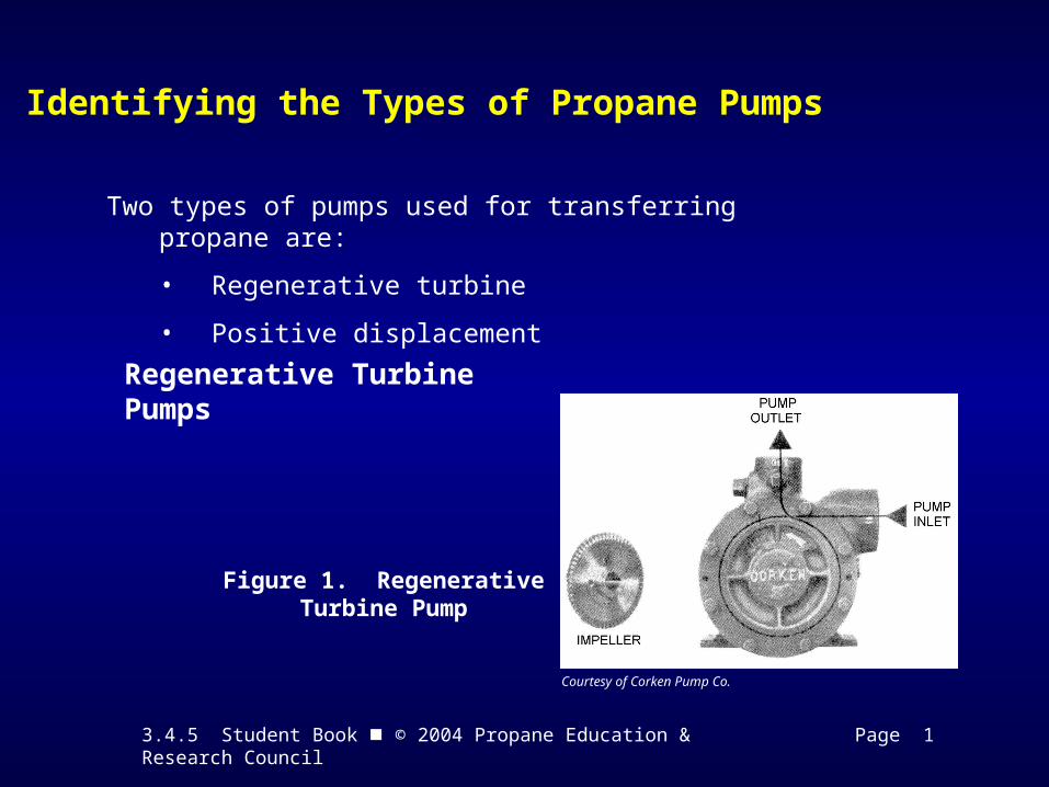
Two types of pumps used for transferring propane are:
• Regenerative turbine
• Positive displacement
Regenerative Turbine Pumps
Figure 1. Regenerative Turbine Pump
Courtesy of Corken Pump Co.

3.4.5 Student Book © 2004 Propane Education & Research Council Page 2
Identifying the Types of Propane Pumps
Regenerative Turbine Pumps
Figure 1. Regenerative Turbine Pump
Courtesy of Corken Pump Co.

3.4.5 Student Book © 2004 Propane Education & Research Council Page 2
Identifying the Types of Propane Pumps
Regenerative Turbine Pumps— Regenerative turbine pumps are used at cylinder docks, dispensing stations, and in other applications that require capacities of up to 25 gallons per minute.
Figure 1. Regenerative Turbine Pump
Courtesy of Corken Pump Co.
3.4.5 Student Book © 2004 Propane Education & Research Council Page 3
Identifying the Types of Propane Pumps
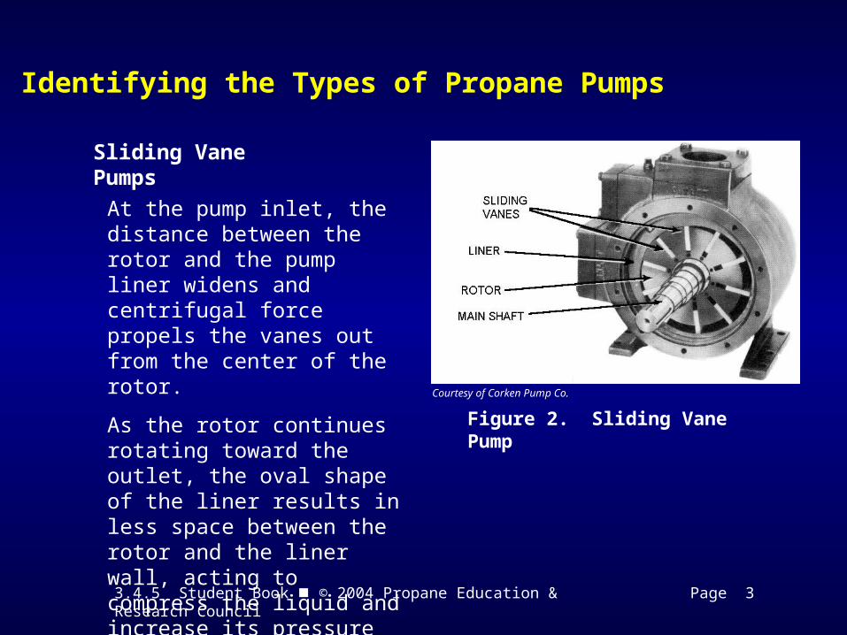
Sliding Vane Pumps
Figure 2. Sliding Vane Pump
Courtesy of Corken Pump Co.
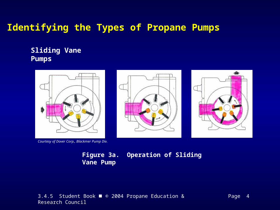
At the pump inlet, the distance between the rotor and the pump liner widens and centrifugal force propels the vanes out from the center of the rotor.
As the rotor continues rotating toward the outlet, the oval shape of the liner results in less space between the rotor and the liner wall, acting to compress the liquid and increase its pressure at the pump’s outlet.
3.4.5 Student Book © 2004 Propane Education & Research Council Page 4
Identifying the Types of Propane Pumps
Sliding Vane Pumps
Figure 3a. Operation of Sliding Vane Pump
Courtesy of Dover Corp., Blackmer Pump Div.
3.4.5 Student Book © 2004 Propane Education & Research Council Page 4
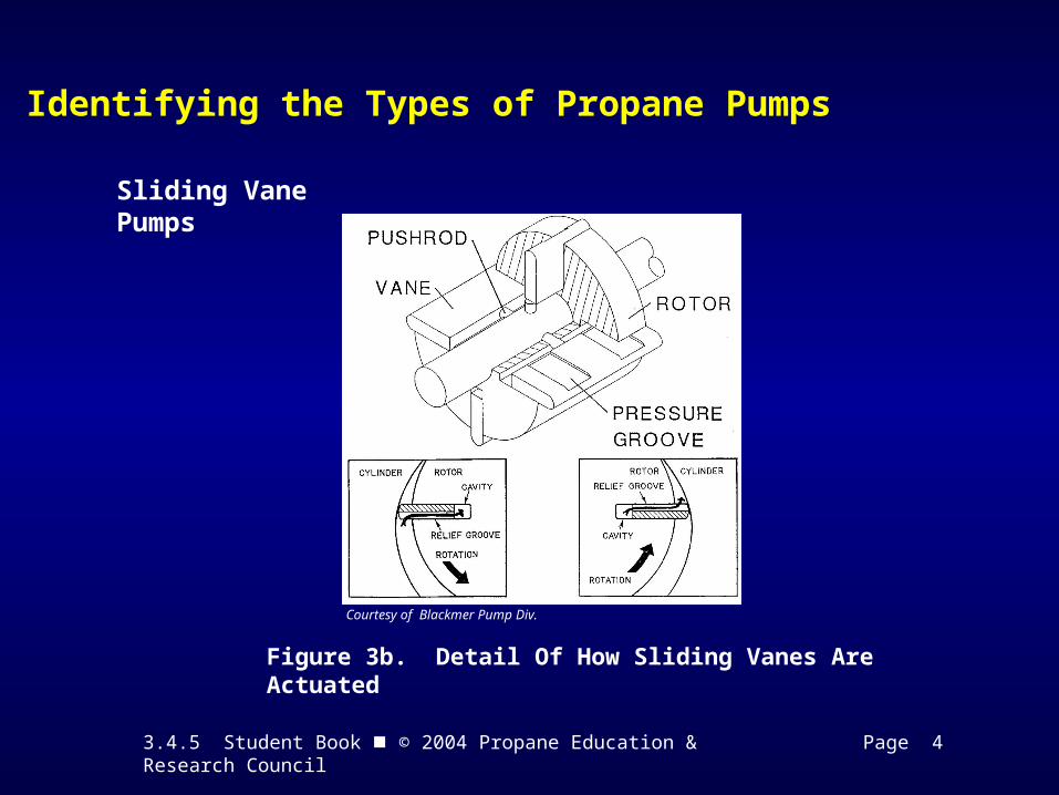
Identifying the Types of Propane Pumps
Sliding Vane Pumps
Figure 3b. Detail Of How Sliding Vanes Are Actuated
Courtesy of Blackmer Pump Div.

3.4.5 Student Book © 2004 Propane Education & Research Council Page 5
Identifying the Types of Propane Pumps
Gear Pumps
Figure 4. Gear Pump
Courtesy of Blackmer Pump Div.
3.4.5 Student Book © 2004 Propane Education & Research Council Page 6
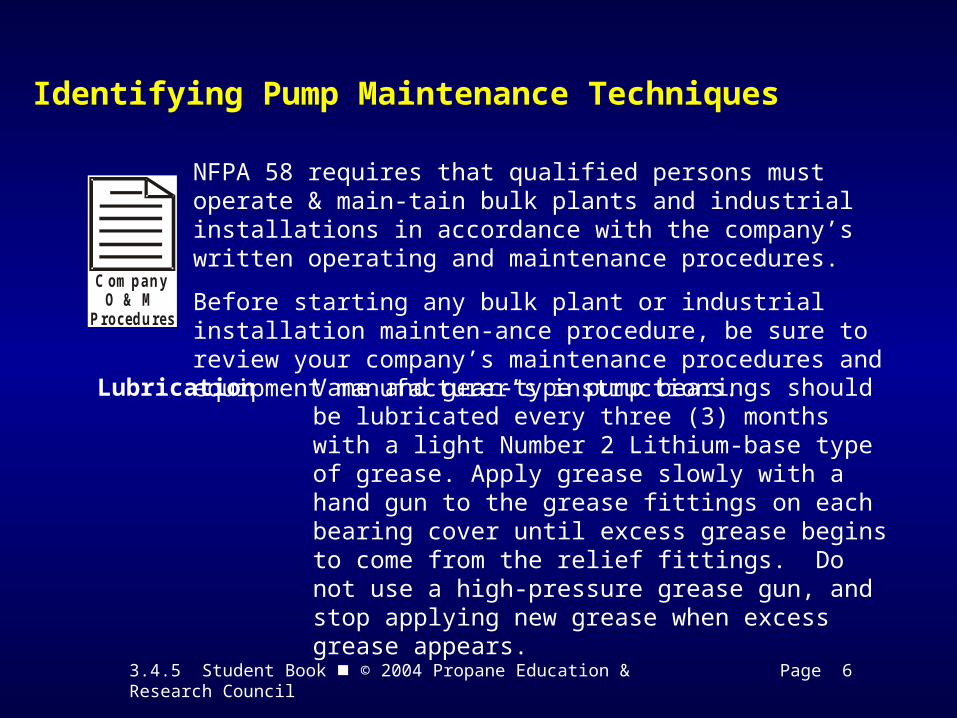
Identifying Pump Maintenance Techniques
C om p a n yO & M
P ro c ed u re s
NFPA 58 requires that qualified persons must operate & main-tain bulk plants and industrial installations in accordance with the company’s written operating and maintenance procedures.
Before starting any bulk plant or industrial installation mainten-ance procedure, be sure to review your company’s maintenance procedures and equipment manufacturer’s instructions.
Lubrication Vane and gear-type pump bearings should be lubricated every three (3) months with a light Number 2 Lithium-base type of grease. Apply grease slowly with a hand gun to the grease fittings on each bearing cover until excess grease begins to come from the relief fittings. Do not use a high-pressure grease gun, and stop applying new grease when excess grease appears.

3.4.5 Student Book © 2004 Propane Education & Research Council Page 6
Identifying Pump Maintenance Techniques
Drive Components
Belt-driven pumps should be examined for proper alignment and condition of the drive belts when lubrication is scheduled.
Shaft coupling-driven pumps should be checked for proper alignment of the couplings and wear of the spacing bushings.
Gear Reduction driven pumps must be checked for proper alignment and wear of their universal joints or couplings as applicable. The gearbox and U-joints should be lubricated according to manufacturer instructions and maintenance recommendations.

3.4.5 Student Book © 2004 Propane Education & Research Council Page 7
Identifying Pump Maintenance Techniques
At all times during the maintenance of pumps and their drive components, electrical controls should be locked out and tagged according to company procedures.
If the drive belt and pulley guards or coupling guards are removed during inspection or maintenance operations, they must be properly installed and secured before lock out and tag out devices are removed and the equipment is placed back into service.
3.4.5 Student Book © 2004 Propane Education & Research Council Page 7
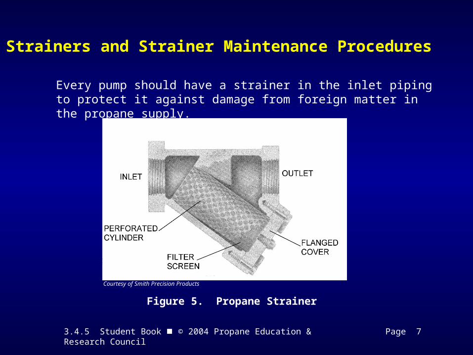
Strainers and Strainer Maintenance Procedures
Every pump should have a strainer in the inlet piping to protect it against damage from foreign matter in the propane supply.
Figure 5. Propane Strainer
Courtesy of Smith Precision Products
3.4.5 Student Book © 2004 Propane Education & Research Council Page 8
Strainers and Strainer Maintenance Procedures
Selecting and Sizing Strainers
• Most manufacturers recommend that the installed strainer be at least one pipe size larger than the inlet piping.
• They also recommend a strainer with as large a screen area as possible, and to locate it at least ten pipe diameters upstream from the pump inlet, whenever possible.
Strainer Maintenance
• The strainer must be isolated from the rest of the transfer system by closing liquid piping valves upstream and downstream of the strainer.
• Propane trapped in the strainer must be bled off safely.
• The cover must be removed from the bottom of the strainer body or casing and be cleaned using a brass bristle brush and a solvent if necessary.
3.4.5 Student Book © 2004 Propane Education & Research Council Page 9
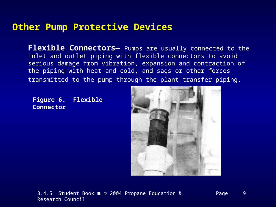
Other Pump Protective Devices
Flexible Connectors— Pumps are usually connected to the inlet and outlet piping with flexible connectors to avoid serious damage from vibration, expansion and contraction of the piping with heat and cold, and sags or other forces
transmitted to the pump through the plant transfer piping.
Figure 6. Flexible Connector
3.4.5 Student Book © 2004 Propane Education & Research Council Page 11
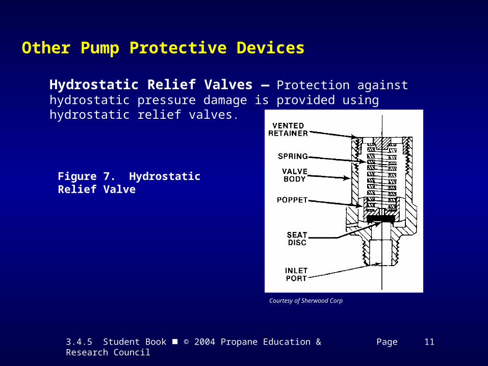
Other Pump Protective Devices
Hydrostatic Relief Valves — Protection against hydrostatic pressure damage is provided using hydrostatic relief valves.
Figure 7. Hydrostatic Relief Valve
Courtesy of Sherwood Corp

3.4.5 Student Book © 2004 Propane Education & Research Council Page 12
Other Pump Protective Devices
Selecting and Maintaining Hydrostatic Relief Valves —Hydrostatic relief valves must be designed to open at a pressure of not less than 400 psig and not more than 500 psig when selecting new or replacement valves.
Figure 8. Hydrostatic Relief Valves With Rain Caps
Hydrostatic relief valves should be fitted with rain caps to prevent moisture and debris from accumulating inside the valve.
3.4.5 Student Book © 2004 Propane Education & Research Council Page 13
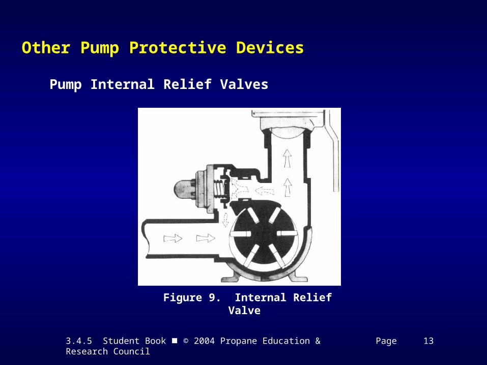
Other Pump Protective Devices
Pump Internal Relief Valves
Figure 9. Internal Relief Valve
3.4.5 Student Book © 2004 Propane Education & Research Council Page 14
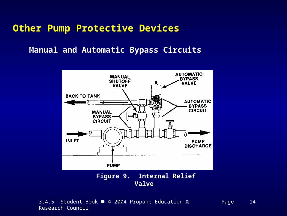
Other Pump Protective Devices
Manual and Automatic Bypass Circuits
Figure 9. Internal Relief Valve
3.4.5 Student Book © 2004 Propane Education & Research Council Page 15
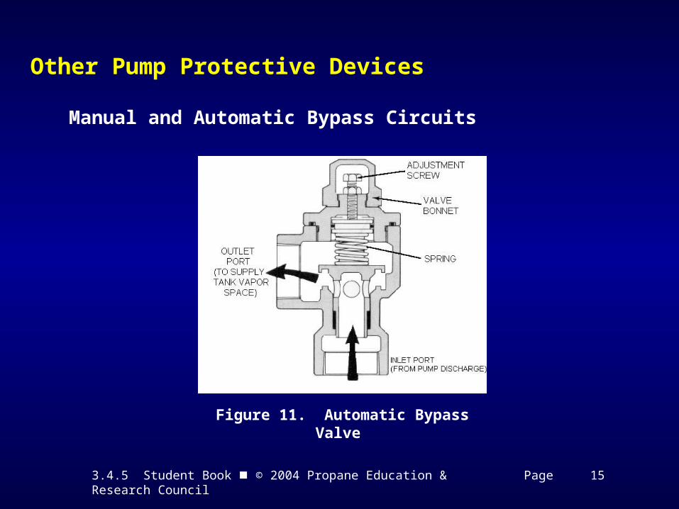
Other Pump Protective Devices
Manual and Automatic Bypass Circuits
Figure 11. Automatic Bypass Valve
3.4.5 Student Book © 2004 Propane Education & Research Council Page 16
Other Pump Protective Devices
Maintaining Automatic Bypass Valves
The bypass valve should be set at least 15 to 20 psi below the pump’s internal relief valve setting. Qualified personnel using properly selected liquid-filled pressure gauges (rated for 0-400 psig service) can adjust the valve’s opening setting if the automatic bypass is not opening at the proper pressure to protect the pump.
To determine the automatic bypass opening setting or to adjust the setting, follow your company’s written maintenance procedures and equipment manufacturer instructions.
3.4.5 Student Book © 2004 Propane Education & Research Council Pages 18 - 20
Time to See If You Got the Key Points of This Module…
• Complete the Review on pages 18 & 19.
• See if you are ready for the Certification Exam by checking off the performance criteria on page 20.