3341906 pms lab_manual_prepared by vipul hingu
44
LAB MANUAL Prepared By Mr. Vipul Hingu B.E. (Mech.) PLANT MAINTENANCE & SAFETY SUBJECT CODE :- 3341906 S.B. POLYTECHNIC
-
Upload
vipul-hingu -
Category
Engineering
-
view
34 -
download
6
Transcript of 3341906 pms lab_manual_prepared by vipul hingu

LAB
MANUAL
Prepared By
Mr. Vipul Hingu
B.E. (Mech.)
PLANT MAINTENANCE & SAFETY
SUBJECT CODE :- 3341906
S.B. P
OLYTECHNIC
LAB PRACTICAL LIST S.B. POLYTECHNIC, SAVLI PMS (3341906)
Prepared By Mr. Vipul Hingu
LAB PRACTICAL LIST
Practical No. Aim of Practical
1 Preparatory Activity
2 Measurement of Wear
3 Corrosion
4 Fault Tracing and Decision Tree
5 Maintenance of Mechanical Devise
6 Preventive Maintenance
7 Safety
8 Test Chart of Newly Installed
Machine
S.B. P
OLYTECHNIC

EXPERIMENT NO. 1 S.B. POLYTECHNIC, SAVLI PMS (3341906)
Prepared By Mr. Vipul Hingu Page 1 of 3
EXPERIMENT NO. 1
AIM: - To Study and Demonstrate Use of Various Types of Tools.
There are many types of tools, as following.
(1) PLIERS
(2) SPANNERS
(3) ALLEN KEY
(4) FILES
(5) RIGHT ANGLE
(6) SCREW DRICER
(7) WIRE STRIPPER
(8) CUTTER HANDLES OF CUTTERS
(1) PLIERS
Pliers are a hand tool used to hold object firmly, or for cutting and bending tough
materials such as wires. These types are designed to deal with different types of jobs.
There are different types as following
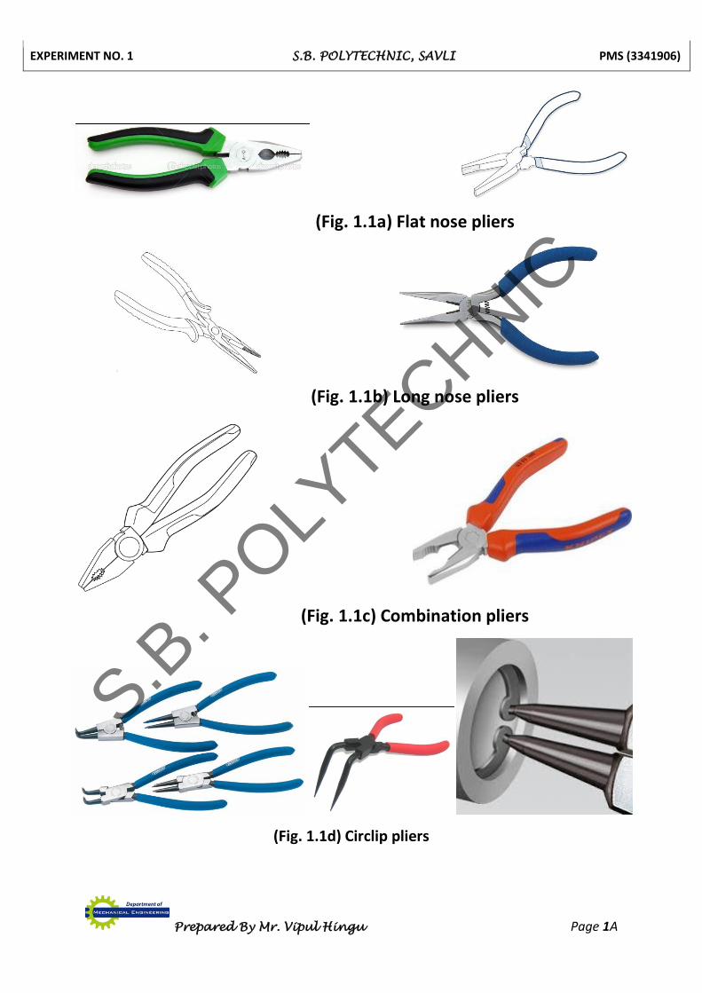
(A) Nose pliers
(a) Flat nose pliers
These are used to hold pins and small objet when small objects
when working in confined spaces. Fig. 1.1a shows a Flat nose plier.
(b) Long nose pliers
Long nose pliers are both cutting and gripping pliers used by
electricians and other tradesmen to bend, re-position and cut wire. Fig.
1.1b shows a Long nose plier.
(B) Combination pliers
These pliers incorporate side cutters, joint cutters and pipe grip. It is used to
hold at or twist wire. Its handle is also inswated. It’s available in lengths of 150mm,
200mm, and 250mm. This type of pliers should not be used to cut steel wire. It
should not be used hammer. Fig. 1.1c shows a Combination plier.
(C) Circlip pliers
Circlip are retaining devices. They are fitted inside a groove on bores and
shafts. The internal Circlip has to be squeezed to be removed and the external Circlip
which is fitted on to a shaft has to be opened out to be removed. The nose is either
straight or bent depending on the type of job. Fig. 1.1d shows a Circlip plier.
S.B. P
OLYTECHNIC
EXPERIMENT NO. 1 S.B. POLYTECHNIC, SAVLI PMS (3341906)
Prepared By Mr. Vipul Hingu Page 1A
(Fig. 1.1a) Flat nose pliers
(Fig. 1.1b) Long nose pliers
(Fig. 1.1c) Combination pliers
(Fig. 1.1d) Circlip pliers
S.B. P
OLYTECHNIC
EXPERIMENT NO. 1 S.B. POLYTECHNIC, SAVLI PMS (3341906)
Prepared By Mr. Vipul Hingu Page 2 of 3
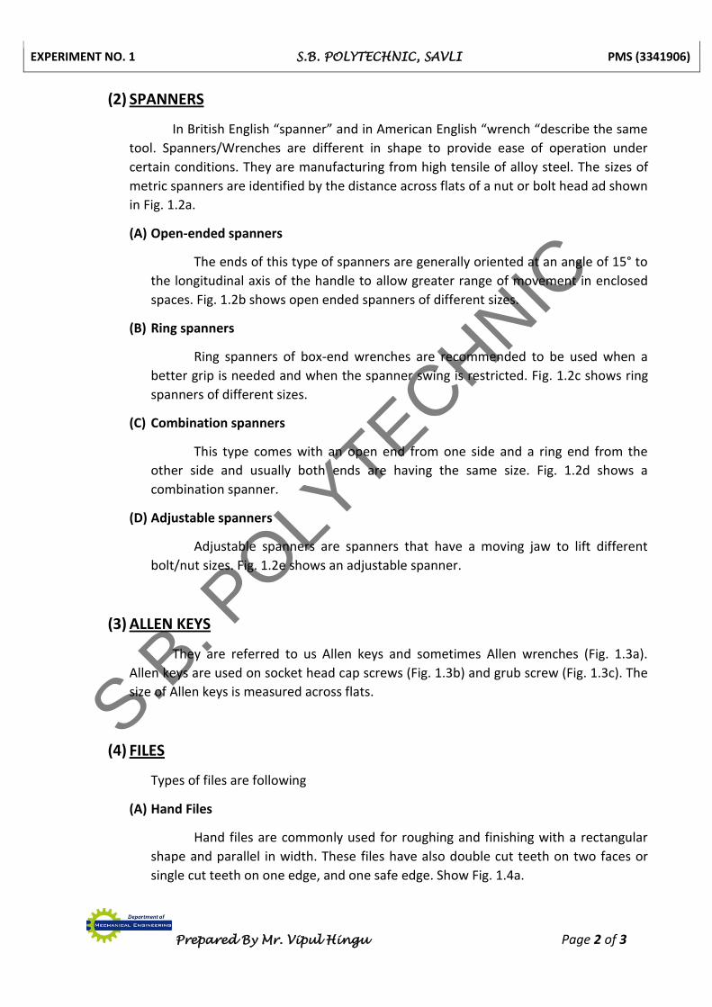
(2) SPANNERS
In British English “spanner” and in American English “wrench “describe the same
tool. Spanners/Wrenches are different in shape to provide ease of operation under
certain conditions. They are manufacturing from high tensile of alloy steel. The sizes of
metric spanners are identified by the distance across flats of a nut or bolt head ad shown
in Fig. 1.2a.
(A) Open-ended spanners
The ends of this type of spanners are generally oriented at an angle of 15° to
the longitudinal axis of the handle to allow greater range of movement in enclosed
spaces. Fig. 1.2b shows open ended spanners of different sizes.
(B) Ring spanners
Ring spanners of box-end wrenches are recommended to be used when a
better grip is needed and when the spanner swing is restricted. Fig. 1.2c shows ring
spanners of different sizes.
(C) Combination spanners
This type comes with an open end from one side and a ring end from the
other side and usually both ends are having the same size. Fig. 1.2d shows a
combination spanner.
(D) Adjustable spanners
Adjustable spanners are spanners that have a moving jaw to lift different
bolt/nut sizes. Fig. 1.2e shows an adjustable spanner.
(3) ALLEN KEYS
They are referred to us Allen keys and sometimes Allen wrenches (Fig. 1.3a).
Allen keys are used on socket head cap screws (Fig. 1.3b) and grub screw (Fig. 1.3c). The
size of Allen keys is measured across flats.
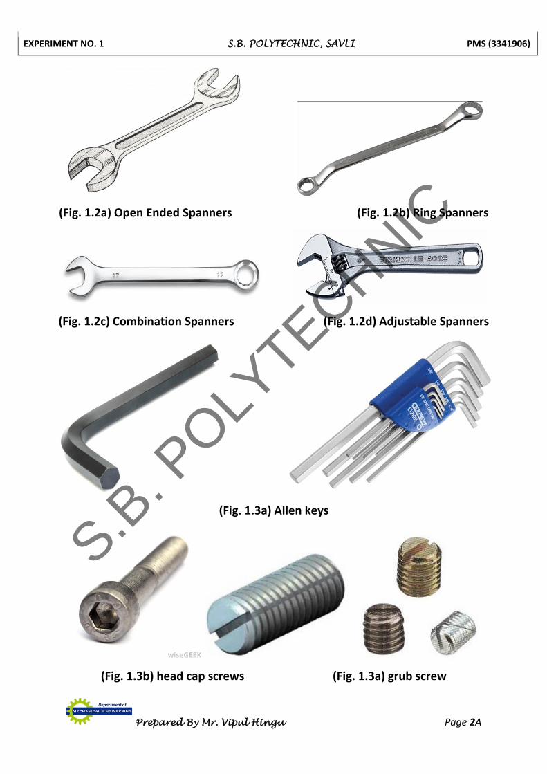
(4) FILES
Types of files are following
(A) Hand Files
Hand files are commonly used for roughing and finishing with a rectangular
shape and parallel in width. These files have also double cut teeth on two faces or
single cut teeth on one edge, and one safe edge. Show Fig. 1.4a.
S.B. P
OLYTECHNIC
EXPERIMENT NO. 1 S.B. POLYTECHNIC, SAVLI PMS (3341906)
Prepared By Mr. Vipul Hingu Page 2A
(Fig. 1.2a) Open Ended Spanners (Fig. 1.2b) Ring Spanners
(Fig. 1.2c) Combination Spanners (Fig. 1.2d) Adjustable Spanners
(Fig. 1.3a) Allen keys
(Fig. 1.3b) head cap screws (Fig. 1.3a) grub screw
S.B. P
OLYTECHNIC
EXPERIMENT NO. 1 S.B. POLYTECHNIC, SAVLI PMS (3341906)
Prepared By Mr. Vipul Hingu Page 3 of 3
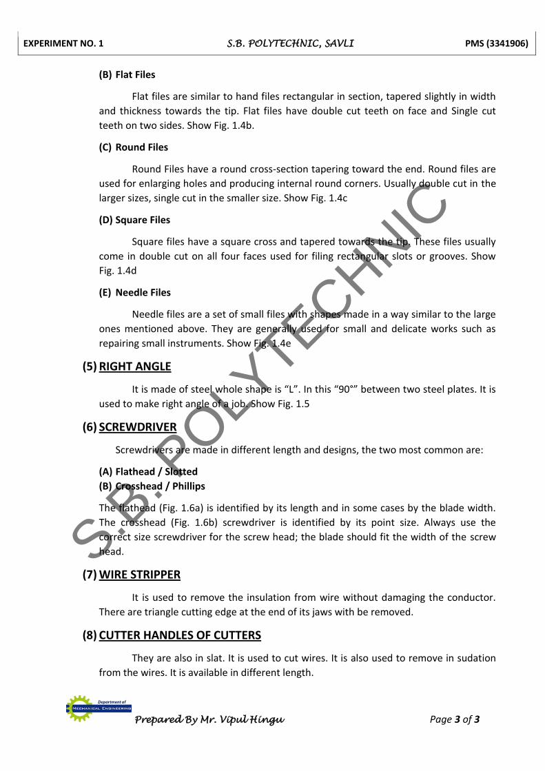
(B) Flat Files
Flat files are similar to hand files rectangular in section, tapered slightly in width
and thickness towards the tip. Flat files have double cut teeth on face and Single cut
teeth on two sides. Show Fig. 1.4b.
(C) Round Files
Round Files have a round cross-section tapering toward the end. Round files are
used for enlarging holes and producing internal round corners. Usually double cut in the
larger sizes, single cut in the smaller size. Show Fig. 1.4c
(D) Square Files
Square files have a square cross and tapered towards the tip. These files usually
come in double cut on all four faces used for filing rectangular slots or grooves. Show
Fig. 1.4d
(E) Needle Files
Needle files are a set of small files with shapes made in a way similar to the large
ones mentioned above. They are generally used for small and delicate works such as
repairing small instruments. Show Fig. 1.4e
(5) RIGHT ANGLE
It is made of steel whole shape is “L”. In this “90°” between two steel plates. It is
used to make right angle of a job. Show Fig. 1.5
(6) SCREWDRIVER
Screwdrivers are made in different length and designs, the two most common are:
(A) Flathead / Slotted
(B) Crosshead / Phillips
The flathead (Fig. 1.6a) is identified by its length and in some cases by the blade width.
The crosshead (Fig. 1.6b) screwdriver is identified by its point size. Always use the
correct size screwdriver for the screw head; the blade should fit the width of the screw
head.
(7) WIRE STRIPPER
It is used to remove the insulation from wire without damaging the conductor.
There are triangle cutting edge at the end of its jaws with be removed.
(8) CUTTER HANDLES OF CUTTERS
They are also in slat. It is used to cut wires. It is also used to remove in sudation
from the wires. It is available in different length.
S.B. P
OLYTECHNIC

EXPERIMENT NO. 1 S.B. POLYTECHNIC, SAVLI PMS (3341906)
Prepared By Mr. Vipul Hingu Page 3A
(Fig. 1.4a) Flat files (Fig. 1.4b) Round Files
(Fig. 1.4c) Square files
(Fig. 1.5) Right Angle (Fig. 1.6a) Flathead Screwdriver
(Fig. 1.6b) Crosshead Screwdriver
S.B. P
OLYTECHNIC
EXPERIMENT NO. 2 S.B. POLYTECHNIC, SAVLI PMS (3341906)
Prepared By Mr. Vipul Hingu Page 1 of 2
EXPERIMENT NO. 2
AIM: - To Measure wares of Different Machine Parts.
We are study ware measurement of following Machine Parts.
(1) Wear of Cylindrical Shaft
(2) Wear of Piston
(3) Wear of Guide Ways
(4) Wear of Threads
(1) Cylindrical Shaft
When cylindrical shaft is in use following faults are developed in it:
1. Wearing of the shaft journal.
2. Wearing of key-way and splines of the shaft.
3. Wearing of threads cut on the shaft surface.
4. Damage occurs to the centre hole.
5. Shaft may bend.
How the repairing of the shaft is to be done is depends upon the amount and type of
wear. When centre hole is ok, the scratches can be removed by grinding to repair the
journal. If the wear is within 0.1 mm then this is possible but if the wear is more on shaft
journal then it can be repaired by turning & grinding reducing journal size below its original
dimension. But at that time it is borne in mind that the reduction in diameter can be done
within the limit of 5 to 10 present only when the shaft is carrying impact load. In such cases
sleeve can be fixed on the journal with the help epoxy-glue for repairing the shaft. Again the
shaft journal can be restored by providing a layer of metal by arc welding, metal spraying
and chromium plating and the original dimension of journal can be obtained by subsequent
machining.
When the diameter of the shaft is more than 60 mm then after heating the
straightening is done. Key way of the shaft can be restored by weld metal filling and cutting
it by milling or slotting to its original dimensions. The original keyway with excessive wear
should be blocked by weld metal filling and the new key way is cut at 90® to the original
one. Threads and splines can be repaired by arc welding and machining.
(2) Piston
The dimension of piston ring grooves and gudgeon pin hole changes due to wear of
the piston-cracks are developed on the piston crown and scratches forms on its cylindrical
surfaces. The gudgeon pin hole is corrected using special reamer. The gudgeon pin and
condition in which the piston is to be used the gudgeon pin is fitted in the hole. The
scratches from the crown and cylindrical surfaces are removed by filing them using a
S.B. P
OLYTECHNIC
EXPERIMENT NO. 2 S.B. POLYTECHNIC, SAVLI PMS (3341906)
Prepared By Mr. Vipul Hingu Page 1A
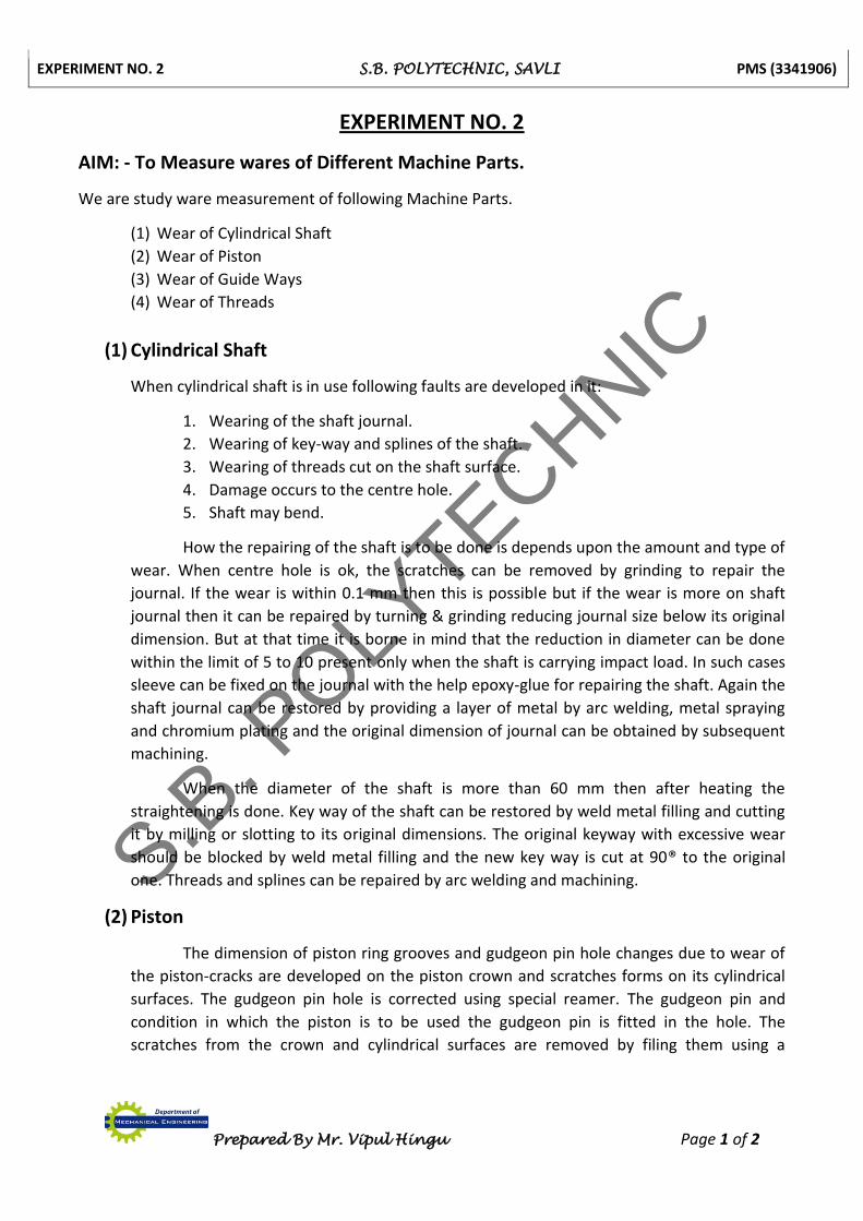
(Fig. 2.1) Wear of Guide-ways
(Fig. 2.2) Wear of Thread
S.B. P
OLYTECHNIC

EXPERIMENT NO. 2 S.B. POLYTECHNIC, SAVLI PMS (3341906)
Prepared By Mr. Vipul Hingu Page 2 of 2
smooth file however it is advisable to replace the cracked piston. Piston ring grooves are
turned to the nearest repair size.
(3) Wear of Guide ways
As per the shape, type and size of the guide way, a universal bridge is placed on it as
shown in Fig 2.1. The thrust pads are then adjusted to bring the zero setting of the level.
With the help of this universal bridge the dial gauge readings are taken to decide the
straightness, parallelism and bending of the guide bed. Based on the dial gauge reading
taken, the amount of wear is calculated. Thereafter scrapping, grinding and planning is done
to carry out the repair of the guide-ways, the bending of the guide-ways are removed &
corrected by using the clamp and lever.
(4) Wear of Threads
Wear of threads is measure by after assembly of Nut & Bolt and showing side play of
this assembly. Wear of threads is measure by thread micrometre. Wear of thread is also
measure by thread gauge and Go-No Go gauge. Measure of pitch circle diameter is using
three wires which are shown in Fig. 2.2. Adjustment of three wires for measuring pitch circle
diameter and calculation is following.
Mw = Up dimension of wire.
W = Diameter of wire.
N = Number of threads in unit length.
Pd = Pitch circle diameter of thread which in wear condition.
Pd = Mw + 0.86
𝑁 – 3w
S.B. P
OLYTECHNIC

EXPERIMENT NO. 3 S.B. POLYTECHNIC, SAVLI PMS (3341906)
Prepared By Mr. Vipul Hingu Page 1 of 4
EXPERIMENT NO. 3
AIM: - To Study About Corrosion and its Effects & Prevention Methods.
We are study about Corrosion and its Effects & Prevention Methods.
CORROSION
Corrosion is the deterioration or destruction of metals and alloys in the presence of an environment by chemical or electrochemical means. In simple terminology, corrosion processes involve reaction of metals with environmental species.
What follows is a simple explanation of how corrosion occurs, what the different
types are how problems can be solved. It is intended to be used by the non-expert to gain an initial appreciation of the subject before exploring further.
HOW DOES IT HAPPEN?
WHAT WE ALL KNOW We have all seen corrosion and know that the process produces a new and less
desirable material from the original metal and can result in a loss of function of the component or system. The corrosion product we see most commonly is the rust which forms on the surface of steel and somehow
Steel → Rust TWO REACTIONS
For this to happen the major component of steel, iron (Fe) at the surface of a component undergoes a number of simple changes. Firstly,
Fe + Fen+ + n electrons The iron atom can lose some electrons and become a positively charged ion. This allows it to bond to other groups of atoms that are negatively charged.
We know that wet steel rusts to give a variant of iron oxide so the other half of the reaction must involve water (H2O) and oxygen (O2) something like this
O2 + 2H2O + 4e- + 4OH-
This makes sense as we have a negatively charged material that can combine with the iron and electrons, which are produced in the first reaction, are used up. We can, for clarity, ignore the electrons and write
2Fe + O2 + 2H2O + 2Fe (OH) 2 Iron + Water with oxygen + Iron Hydroxide
Dissolved in it Oxygen dissolves quite readily in water and because there is usually an excess of it, reacts with the iron hydroxide.
4Fe (OH) 2 + O2 2H2O + 2Fe2O3.H2O
Iron hydroxide + oxygen → water + Hydrated iron oxide (Brown rust)
THE PROCESS (Five facts)
S.B. P
OLYTECHNIC

EXPERIMENT NO. 3 S.B. POLYTECHNIC, SAVLI PMS (3341906)
Prepared By Mr. Vipul Hingu Page 2 of 4
(1) Ions are involved and need a medium to move in (usually water) (2) Oxygen is involved and needs to be supplied (3) The metal has to be willing to give up electrons to start the process (4) A new material is formed and this may react again or could be protective of the
original metal (5) A series of simple steps are involved and a driving force is needed to achieve
them
CORROSION TYPES & ITS CAUSES AND PREVENTION
UNIFORM CORROSION 30% of failures
Uniform corrosion, as the name suggests, occurs over the majority of the surface of a metal at a steady and often predictable rate. Although it is unsightly its predictability facilitates easy control, the most basic method being to make the material thick enough to function for the lifetime of the component. Uniform corrosion can be slowed or stopped by using the five basic facts;
(1) Slow down or stop the movement of electrons (a) Coat the surface with a non-conducting medium such as paint, lacquer or oil (b) Reduce the conductivity of the solution in contact with the metal an extreme
case being to keep it dry. Wash away conductive pollutants regularly. (c) Apply a current to the material (see cathodic protection).
(2) Slow down or stop oxygen from reaching the surface. Difficult to do completely but coatings can help.
(3) Prevent the metal from giving up electrons by using a more corrosion resistant metal higher in the electrochemical series. Use a sacrificial coating which gives up its electrons more easily than the metal being protected. Apply cathodic protection. Use inhibitors.
(4) Select a metal that forms an oxide that is protective and stops the reaction. Control and consideration of environmental and thermal factors is also essential. LOCALISED CORROSION 70% of failures
The consequences of localised corrosion can be a great deal more severe than uniform corrosion generally because the failure occurs without warning and after a surprisingly short period of use or exposure. Application of the five basic facts needs greater thought and insight.
(1) GALVANIC CORROSION
This can occur when two different metals are placed in contact with each other
and are caused by the greater willingness of one to give up electrons than the other. Three special features of this mechanism need to operate for corrosion to occur:
The metals need to be in contact electrically
One metal needs to be significantly better at giving up electrons than other
An additional path for ion and electron movement is necessary Prevention of this problem is based on ensuring that one or more of the three features do not exist.
S.B. P
OLYTECHNIC

EXPERIMENT NO. 3 S.B. POLYTECHNIC, SAVLI PMS (3341906)
Prepared By Mr. Vipul Hingu Page 3 of 4
Break the electrical contact using plastic insulators or coatings between the metals.
Select metals close together in the galvanic series.
Prevent ion movement by coating the junction with an impermeable material, or ensure environment is dry and liquids cannot be trapped.
(2) PITTING CORROSION Pitting corrosion occurs in materials that have a protective film such as a
corrosion product or when a coating breaks down. The exposed metal gives up electrons easily and the reaction initiates tiny pits with localised chemistry supporting rapid attack. Control can be ensured by:
Selecting a resistant material
Ensuring a high enough flow velocity of fluids in contact with the material or frequent washing
Control of the chemistry of fluids and use of inhibitors
Use of a protective coating
Maintaining the material’s own protective film
(3) SELECTIVE ATTACK
This occurs in alloys such as brass when one component or phase is more susceptible to attack than another and corrodes preferentially leaving a porous material that crumbles. It is best avoided by selection of a resistant material but other means can be effective such as:
Coating the material
Reducing the aggressiveness of the environment
Use of cathodic protection
(4) STRESS CORROSION CRACKING
The combined action of a static tensile stress and corrosion which forms cracks and eventually catastrophic failure of the component. This is specific to a metal material paired with a specific environment. Prevention can be achieved by:
Reducing the overall stress level and designing out stress concentrations
Selection of a suitable material not susceptible to the environment
Design to minimise thermal and residual stresses
(5) STRAY CURRENT CORROSION
When a direct current flows through an unintended path and the flow of electrons supports corrosion. This can occur in soils and flowing or stationary fluids. The most effective remedies involve controlling the current by:
Insulating the structure to be protected or the source of current
Earthling sources and/or the structure to be protected.
Applying cathodic protection
S.B. P
OLYTECHNIC
EXPERIMENT NO. 3 S.B. POLYTECHNIC, SAVLI PMS (3341906)
Prepared By Mr. Vipul Hingu Page 4 of 4
Using sacrificial targets
(6) CORROSION CAUSED BY COMBINED ACTION
This is corrosion accelerated by the action of fluid flow sometimes with the added pressure of abrasive particles in the stream. The protective layers and corrosion products of the metal are continually removed exposing fresh metal to corrosion. Prevention can be achieved by:
Reducing the flow rate and turbulence
Use of replaceable or robust linings in susceptible areas
Avoiding sudden changes of direction
Streamlining or avoiding obstructions to the flow
(7) CORROSION FATIGUE
The combined action of cyclic stresses and a corrosive environment reduce the life of components below that expected by the action of fatigue alone. This can be reduced or prevented by;
Coating the material
Good design that reduces stress concentration
Avoiding sudden changes of section
Removing or isolating sources of cyclic stress
EFFECTS OF CORROSION Some of the major harmful effects of corrosion can be summarised as follows (1) Reduction of metal thickness leading to loss of mechanical strength and structural failure
or breakdown. When the metal is lost in localised zones so as to give a crack like structure, very considerable weakening may result from quite a small amount of metal loss.
(2) Hazards or injuries to people arising from structural failure or breakdown (e.g. bridges, cars, aircraft).
(3) Loss of time in availability of profile-making industrial equipment. (4) Reduced value of goods due to deterioration of appearance. (5) Contamination of fluids in vessels and pipes (e.g. beer goes cloudy when small quantities
of heavy metals are released by corrosion). (6) Mechanical damage to valves, pumps, etc., or blockage of pipes by solid corrosion
products. (7) Added complexity and expense of equipment which needs to be designed to withstand a
certain amount of corrosion, and to allow corroded components to be conveniently replaced.
S.B. P
OLYTECHNIC
EXPERIMENT NO. 4 S.B. POLYTECHNIC, SAVLI PMS (3341906)
Prepared By Mr. Vipul Hingu Page 1 of 12
EXPERIMENT NO. 4
AIM: - Make Fault Tracing & Decision Tree.
We are study fault tracing & decision tree from following items.
(1) BOILER
(2) PUMPS
(3) INTERNAL COMBUSTION (IC) ENGINE
Make Fault Tracing & Decision Tree for following items
(1) LATHE MACHINE
(2) MILLING MACHINE
(3) DRILLING MACHINE
(1) BOILER
Fault: - Low steam pressure in a Boiler:
Due to Leakage of steam, Low water level in boiler, wrong setting of furnace, less
fuel burnt, bigger size of coal, moisture in the coal, wrong adjustment of pressure of
regulating value and faulty pressure are causing the low steam pressure in a boiler. The
reasons for these faults are listed below as per the logical sequence.
Reasons:
(1) Low Water Level in Boiler
(2) Steam Leakage
(3) Wrong Furnace Setting
(4) Less Quantity of Fuel Burnt
(5) Fuel Size or Coal size is Bigger
(6) Wrong Adjustment of Pressure Regulating Valve.
(7) Fault in Pressure Gauge
S.B. P
OLYTECHNIC

EXPERIMENT NO. 4 S.B. POLYTECHNIC, SAVLI PMS (3341906)
Prepared By Mr. Vipul Hingu Page 2 of 12
FAULT REASONS DECISION ACTION
1. Low steam pressure in a
Boiler
Low Water Level in Boiler
2. Faulty Remove the fault
3. Not Faulty Go to next
Steam Leakage
4. Faulty Remove the fault
5. Not Faulty Go to next
Wrong Furnace Setting
6. Faulty Remove the fault
7. Not Faulty Go to next
Less Quantity of Fuel Burnt
8. Faulty Remove the fault
9. Not Faulty Go to next
Fuel Size or Coal size is
Bigger
10. Faulty Remove the fault
11. Not Faulty Go to next
Wrong Adjustment of
Pressure Regulating
Valve
12. Faulty Remove the fault
13. Not Faulty Go to next
Fault in Pressure Gauge
14. Faulty Remove the fault
15. Not Faulty Go to next
S.B. P
OLYTECHNIC

EXPERIMENT NO. 4 S.B. POLYTECHNIC, SAVLI PMS (3341906)
Prepared By Mr. Vipul Hingu Page 3 of 12
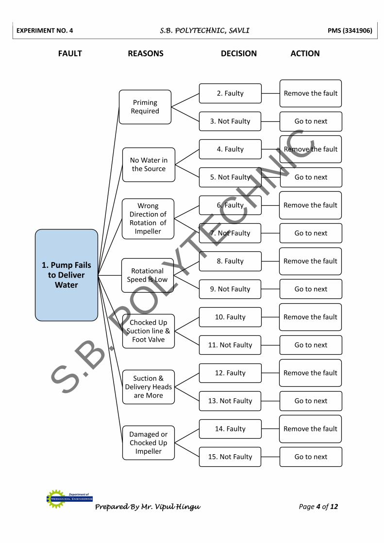
(2) PUMPS
Fault: - Pump Fails to Deliver Water
The pump fails to deliver water due to its failure to suck the water from the source.
The accumulation of dirt and air in the suction line & its casing are the probable reasons for
its failure. Pump capacity, more heads, jammed bearing, low speed or rotation of impeller,
damaged packing and chocked up foot valve are the other reasons. To remove the fault of
the pump the following logically arranged reasons are checked & rectified.
Reasons:
(1) Priming Required
(2) No Water in the Source
(3) Wrong Direction of Rotation
(4) Rotational Speed is Low
(5) Suction line and Foot Valve are Chocked Up
(6) More Suction & Delivery Heads
(7) Damaged or Chocked Up Impeller
S.B. P
OLYTECHNIC
EXPERIMENT NO. 4 S.B. POLYTECHNIC, SAVLI PMS (3341906)
Prepared By Mr. Vipul Hingu Page 4 of 12
FAULT REASONS DECISION ACTION
1. Pump Fails to Deliver
Water
Priming Required
2. Faulty Remove the fault
3. Not Faulty Go to next
No Water in the Source
4. Faulty Remove the fault
5. Not Faulty Go to next
Wrong Direction of Rotation of
Impeller
6. Faulty Remove the fault
7. Not Faulty Go to next
Rotational Speed is Low
8. Faulty Remove the fault
9. Not Faulty Go to next
Chocked Up Suction line &
Foot Valve
10. Faulty Remove the fault
11. Not Faulty Go to next
Suction & Delivery Heads
are More
12. Faulty Remove the fault
13. Not Faulty Go to next
Damaged or Chocked Up
Impeller
14. Faulty Remove the fault
15. Not Faulty Go to next
S.B. P
OLYTECHNIC
EXPERIMENT NO. 4 S.B. POLYTECHNIC, SAVLI PMS (3341906)
Prepared By Mr. Vipul Hingu Page 5 of 12
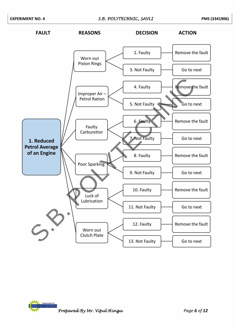
(3) INTERNAL COMBUSTION (IC) ENGINE
Fault: - Reduced Petrol Average of an Engine
In a Car and Scooter like engines the distance covered in kilometre per litre of fuel or
petrol is known as the average of petrol. It is reduced due to leakage of compression, faulty
carburettor, improper mixing poor spark, worn out Dutch plate and improper or insufficient
lubrication. The reasons for reduced petrol average in logical sequence are as follow.
Reasons:
(1) Worn out Piston Rings
(2) Improper Air – Petrol Ration
(3) Faulty Carburettor
(4) Poor Sparking
(5) Luck of Lubrication
(6) Worn out Clutch Plate
S.B. P
OLYTECHNIC
EXPERIMENT NO. 4 S.B. POLYTECHNIC, SAVLI PMS (3341906)
Prepared By Mr. Vipul Hingu Page 6 of 12
FAULT REASONS DECISION ACTION
1. Reduced Petrol Average
of an Engine
Worn out Piston Rings
2. Faulty Remove the fault
3. Not Faulty Go to next
Improper Air –Petrol Ration
4. Faulty Remove the fault
5. Not Faulty Go to next
Faulty Carburettor
6. Faulty Remove the fault
7. Not Faulty Go to next
Poor Sparking
8. Faulty Remove the fault
9. Not Faulty Go to next
Luck of Lubrication
10. Faulty Remove the fault
11. Not Faulty Go to next
Worn out Clutch Plate
12. Faulty Remove the fault
13. Not Faulty Go to nextS.B. P
OLYTECHNIC
EXPERIMENT NO. 4 S.B. POLYTECHNIC, SAVLI PMS (3341906)
Prepared By Mr. Vipul Hingu Page 7 of 12
Make Fault Tracing & Decision Tree for following items
(1) LATHE MACHINE
Fault: - Do not Start Lathe Machine
_____________________________________________________________________
___________________________________________________________________________
___________________________________________________________________________
___________________________________________________________________________
Reasons:
(1) _________________________
(2) _________________________
(3) _________________________
(4) _________________________
(5) _________________________
(6) _________________________
S.B. P
OLYTECHNIC

EXPERIMENT NO. 4 S.B. POLYTECHNIC, SAVLI PMS (3341906)
Prepared By Mr. Vipul Hingu Page 8 of 12
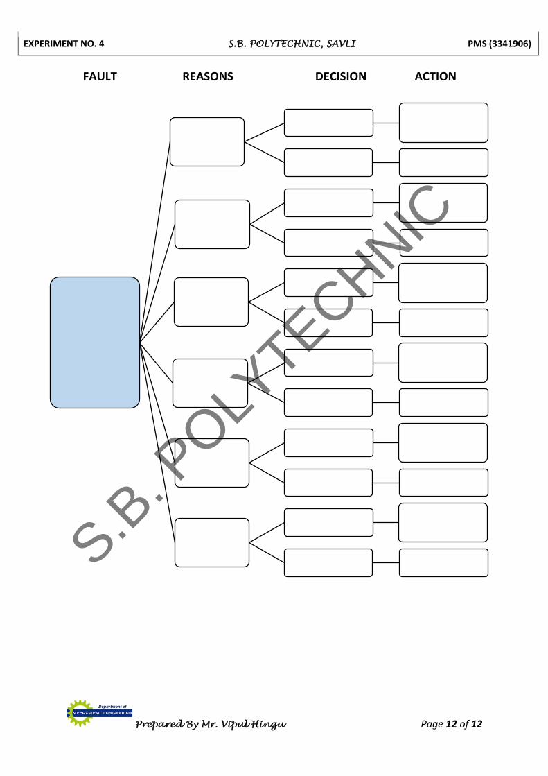
FAULT REASONS DECISION ACTION
S.B. P
OLYTECHNIC

EXPERIMENT NO. 4 S.B. POLYTECHNIC, SAVLI PMS (3341906)
Prepared By Mr. Vipul Hingu Page 9 of 12
(2) MILLING MACHINE
Fault: - Do not Start Milling Machine
_____________________________________________________________________
___________________________________________________________________________
___________________________________________________________________________
___________________________________________________________________________
Reasons:
(1) _________________________
(2) _________________________
(3) _________________________
(4) _________________________
(5) _________________________
(6) _________________________
S.B. P
OLYTECHNIC

EXPERIMENT NO. 4 S.B. POLYTECHNIC, SAVLI PMS (3341906)
Prepared By Mr. Vipul Hingu Page 10 of 12
FAULT REASONS DECISION ACTION
S.B. P
OLYTECHNIC
EXPERIMENT NO. 4 S.B. POLYTECHNIC, SAVLI PMS (3341906)
Prepared By Mr. Vipul Hingu Page 11 of 12
(3) DRILLING MACHINE
Fault: - Do not Start Drilling Machine
_____________________________________________________________________
___________________________________________________________________________
___________________________________________________________________________
___________________________________________________________________________
Reasons:
(1) _________________________
(2) _________________________
(3) _________________________
(4) _________________________
(5) _________________________
(6) _________________________
S.B. P
OLYTECHNIC
EXPERIMENT NO. 4 S.B. POLYTECHNIC, SAVLI PMS (3341906)
Prepared By Mr. Vipul Hingu Page 12 of 12
FAULT REASONS DECISION ACTION
S.B. P
OLYTECHNIC

EXPERIMENT NO. 5 S.B. POLYTECHNIC, SAVLI PMS (3341906)
Prepared By Mr. Vipul Hingu Page 1 of 2
EXPERIMENT NO. 5
AIM: - To Study about Maintenance of Mechanical Based Equipment.
We are study of following maintenance of mechanical based equipment.
(1) PUMPS
(2) AIR COMPRESSOR
(1) PUMPS
Maintenance of Pumps:
(1) Check whether the working of the pump is as per need or not.
(2) Stop the leakages of the pipes and pipe joints.
(3) Clean the filters.
(4) Regulate the discharge pressure by checking it using manometer.
(5) Tighten the loose nut bolts of the pipe joints.
(6) Check the gland, packing etc., tighten them if required. If it is found in damaged
condition, then replace the same.
(7) Overhaul the pump if it is required.
Repairing of gear Pump:
(1) Replace the gears with worm out teeth.
(2) Replace the damaged seals & packing.
(3) Carry out the finishing of the face of gear.
(4) Replace the worm out bearings.
(5) Replace the worm out or broken pump housing.
Repairing of Radial Piston Pump:
(1) Replace the worn out bush of distributor rotor & grind the pump axle.
(2) Remove the wear of piston face by grinding.
(3) Replace the worn out reaction ring.
(4) Replace the piston having worn out cylindrical surface and repair the cylinder by lapping.
(5) Test the pump and know its pressure and capacity.
(6) Replace the worn out piston and piston rings.
(7) Repair the cylinder to make it free from ovality and taper.
(8) Replace oil seal.
(9) Curry out the lapping of pressure control valve.
(10) Damaged pipes & pipe joint should be replaced.
(11) Instead of overhauling the pump, replace it with a new pump.
S.B. P
OLYTECHNIC
EXPERIMENT NO. 5 S.B. POLYTECHNIC, SAVLI PMS (3341906)
Prepared By Mr. Vipul Hingu Page 2 of 2
Repairing of Vane Pump:
(1) The scratches from the face of the disc should be removed by lapping or machining.
(2) If wear or scratches are found on stator then replace it.
(3) Replace the worn out & damaged seals & packing.
(2) AIR COMPRESSOR
Maintenance of Compressor:
(1) Supply of air should be cold and clean for air cleaner. (2) If it necessary then place the filter away from compressor for getting air free from
moisture and acids. (3) Lubricate all points as per the recommendation of manufacturer. (4) Change the lubricating oil when it loses its capacity of lubrication. (5) Before replacing the oil, clean the interior, by opening the cover. (6) Check whether the valves of compressor are in working condition or not. (7) Immediately stop the suction valve leakage on hearing the noise of air which blow-bye. (8) Lubricate the piston rings sufficiently. (9) Replace the valve disc & plate when its wear is less than half of its original dimension of
thickness. (10) Adjust the bearing clearance by decreasing or increasing the shines. (11) Remove the dirt and dust from the exterior surface of inter-cooler and radiator.
(12) Keep compressor always clean from outside to reduce maintenance cost.
(13) Adjust the unloading unit of the control system.
(14) Check and if found necessary then replace cylinder head packing.
(15) Often tighten the cylinder head packing.
(16) Prevent the oil pressure increase or decrease.
(17) Prevent the overheating of the piston.
(18) Check oil level in reservoir & top-up it daily.
(19) Check the pressure of inter-cooler.
(20) Replace the defective pressure switch.
(21) Check the solenoid and replace it if found burnt.
(22) Carry out the setting of pressure spring.
(23) Check the water cooling system & bring it in efficient condition. S.B
. POLY
TECHNIC
EXPERIMENT NO. 6 S.B. POLYTECHNIC, SAVLI PMS (3341906)
Prepared By Mr. Vipul Hingu Page 1 of 6
EXPERIMENT NO. 6
AIM: - To Study about Preventive Maintenance
We are study about Definition, Need and Schedule of Preventive Maintenance.
Definition & Aim for Preventive Maintenance:
The care and servicing by personnel for the purpose of maintaining equipment and facilities
in satisfactory operating condition by providing for systematic inspection, detection, and correction
of incipient failures either before they occur or before they develop into major defects.
Preventive maintenance (PM) is a fundamental, planned maintenance activity designed to
improve equipment life and avoid any unplanned maintenance activity. This maintenance includes:
Systematic inspection
Detection
Correction
Prevention of incipient failures
Preventive maintenance is the foundation of the entire maintenance strategy. Unless the
PM program is effective, all subsequent maintenance strategies take longer to implement, incur
higher costs, and have a higher probability of failure.
Preventive maintenance aims to:
Eliminate unnecessary inspection and maintenance tasks
Implement additional maintenance tasks when and where needed
Focus efforts on the most critical items
In addition, preventive maintenance measures can drastically reduce errors in day-to-day
operations, as well as increase the overall preparedness of plants in the case of an emergency.
The ideal preventive maintenance program would prevent all equipment failure before it
occurs.
Preventive maintenance has the goal of improving equipment life by preventing excess
depreciation and impairment. This maintenance includes but is not limited to:
Adjustments
Cleaning
Lubrication
Repairs
Replacements
Extension of equipment life
S.B. P
OLYTECHNIC
EXPERIMENT NO. 6 S.B. POLYTECHNIC, SAVLI PMS (3341906)
Prepared By Mr. Vipul Hingu Page 2 of 6
Need of Preventive Maintenance in Industry:
The preventive maintenance is necessary in the industries to get quality production, which
can be relied upon along with increased productivity, prevent the break down, reduce the repairing
cost, to modernize the machines, keep the machine in good condition by their regular maintenance
and provide timely maintenance efforts in terms of lubrication, adjustment and repairing.
The industry has to insure the expenses for planning and implementing the preventive
maintenance. But the advantage gain by continuous production and reduced cost of maintenance
and repairing is many times more than the cost of maintenance. If the machines are used for longer
period without attending them for preventive maintenance then breakdown of machines occurs. At
the time of machine break down and unplanned repairing is compulsorily needed to be done. The
preventive maintenance avoids the occurrence of such conditions. Therefore, Preventive
maintenance has become the need of the industry.
Preventive Maintenance Programme and Schedule:
Steps Involved in Preventive Maintenance Programme and Schedule
(1) Training of operators for preventive maintenance.
(2) To give training of preventive maintenance.
(3) To form the group of machines and equipment.
(4) To prepare a list of items to be checked.
(5) To control the inventory using classification and standardization.
(6) To analyse the breakdown.
(7) To develop the acceptance of maintenance by keeping the due importance of
production activities.
(8) To get the support of management for preventive maintenance.
(9) To understand the basic idea of preventive maintenance.
(10) Based on past records of maintenance to prepare the real planning.
(11) To synthesis the acts of running the production continuously and sparing of machines
for maintenance work.
(12) To keep the stock of spare parts needed during preventive maintenance work.
(13) To increase the productivity of machines so as to reduce the cost of production.
Factors Involved in Formulating Programme and Schedule of PM
(1) Availability of the machine.
(2) Presence or availability of skilled workers and fitters.
(3) Stock of materials and spare parts.
(4) Need of inspection frequency.
(5) Importance of machine of equipment.
(6) The need of machine and equipment for production work.
(7) The age, condition and cost of machine.
(8) The requirement of safety standard in an industry.
(9) Hours of which the machine is utilized per day.
S.B. P
OLYTECHNIC
EXPERIMENT NO. 6 S.B. POLYTECHNIC, SAVLI PMS (3341906)
Prepared By Mr. Vipul Hingu Page 3 of 6
(10) Repair complexity of the machine.
(11) Engineering analysis of previous breakdown.
(12) Inform obtained from maintenance manual.
(13) Police of the management.
Schedule based on type of maintenance work
The maintenance work can be divided or grouped in four divisions as follows based
on priority of maintenance work mentioned below:
1. Emergency work
2. Non – Emergency work
3. New work
4. Preventive maintenance
This is list of different type of work as per the priority to attend them. When any
emergency work is pending no attempt is made to carry out in the nonemergency. New
work should be done after completing non-emergency work and preventive maintenance
work is given the last number in the priority of providing attention. The work scheduling
should be done based on the above considerations.
Repair Cycle Concept and Importance
To increase the life of machine, to reduce their breakdowns, to obtain its accuracy and
produce quality product, the following four stages are involved repair cycle.
I – Inspection
S – Small repair
M – Medium repair
C – Complete overhaul
Inspection - (I):
The activities of maintenance included under the stage of Inspection (I) are as under:
(1) Observer the condition of mechanisms by running the machine at its all speeds and feed.
(2) Adjust the cleanness of coupling, clutch, bearing and break etc.
(3) Clean the oil and coolant filters.
(4) Clean the machine from dirt and chips and lubricate by oiling and greasing.
(5) Tighten all the loose nut-bolts.
(6) Replace worn out nut-bolts.
(7) Change the lubricating oil in assemblies at specified time.
S.B. P
OLYTECHNIC
EXPERIMENT NO. 6 S.B. POLYTECHNIC, SAVLI PMS (3341906)
Prepared By Mr. Vipul Hingu Page 4 of 6
Small repair – (S):
The following activities are undertaken in small repair stage:
(1) First carry out all the work as per inspection stage.
(2) Dismantled two or three units into their individual part and clean them.
(3) Parts in which needs repairing should be repaired and kept ready. The parts beyond
repairing should be replaced.
(4) Assemble the units by adjusting proper clearances, test them and if found OK, than
replace on machine bed and then test the machine.
(5) Repair the oil pockets of the guide surfaces.
Medium repair – (M):
(1) Maintenance work as per Inspection and small repair is done first.
(2) Repairing of certain additional units is carried out as per need.
(3) The wear of guide surface is corrected by scrapping and grinding.
(4) The layer of paint is to be applied on the machined surfaces.
(5) After replacing the reconditioned assembly on the machine, its complete testing is done.
(6) The machine is also tested according to the accuracy test.
Complete overhaul – (C):
The following activities are undertaken in this complete overhauling of the machine:
(1) All the units are removed from the machine frame. Thereafter, dismantling of the units
is done into their individual parts. The each part is inspected. The parts are repaired and
replaced according to need and assembly and testing are done for to recondition the
units.
(2) The wear of each part is decided by measuring their dimensions using precision
instruments.
(3) Based on the amount of wear calculated the decision regarding the repairing or
replacing the individual parts are taken.
(4) The units are assembled keeping the clearances as per the advice of the manufacturer.
(5) The reconditioned units are fitted back on the frame to complete the reconditioning
work of the machine.
(6) The machine foundation are checked and repaired to remove its defect.
(7) The scrapping and grinding of the guide surface should be done.
(8) The machine testing is to be carried out by running it at all speeds and feed and also by
producing the job on it.
(9) The job so produced is checked for the accuracy of dimensions.
(10) If the job is found ok as per the quality norms laid down, then the machine can be said
as ok, otherwise necessary corrective steps should be taken to obtain the accuracy of
the reconditioned machine.
S.B. P
OLYTECHNIC

EXPERIMENT NO. 6 S.B. POLYTECHNIC, SAVLI PMS (3341906)
Prepared By Mr. Vipul Hingu Page 5 of 6
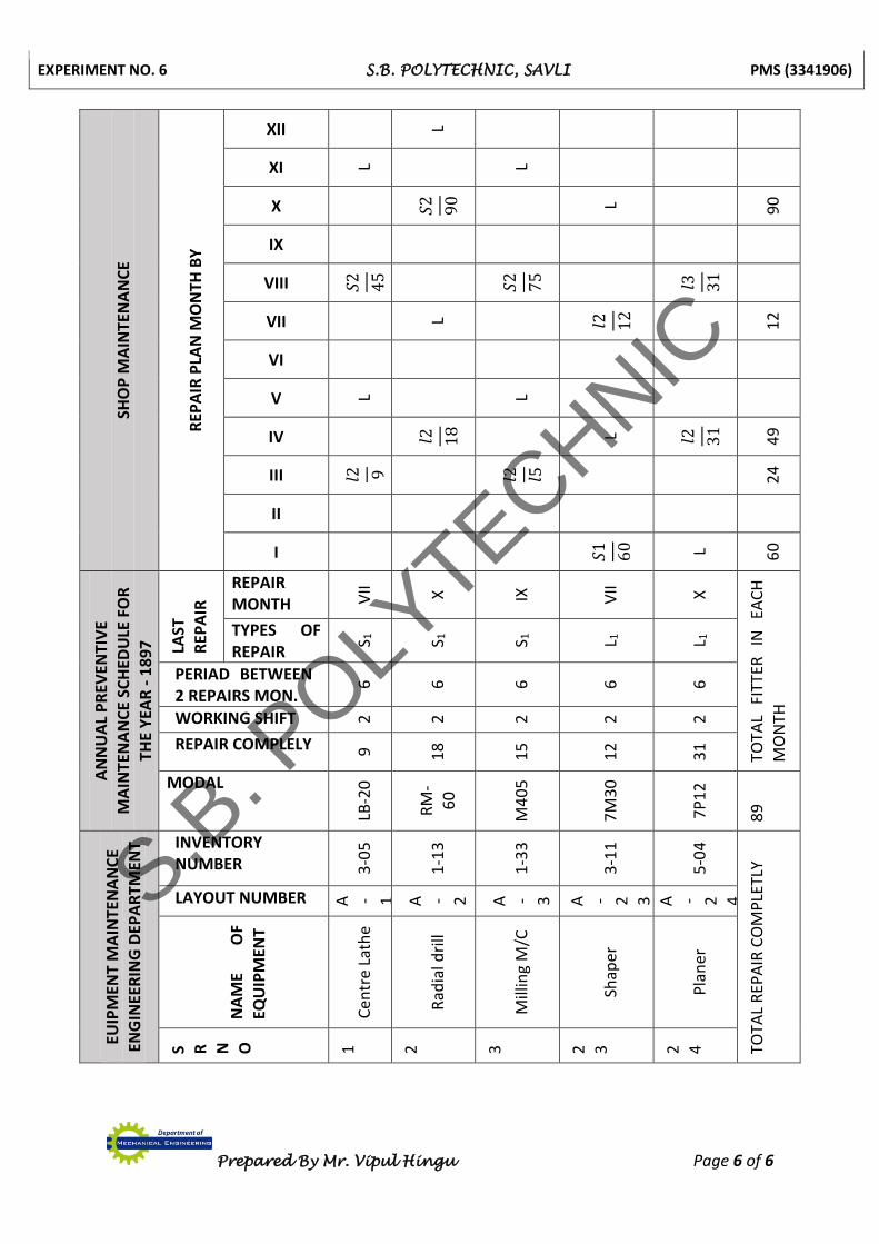
Machines Preventative Maintenance (PM) Program checklist:
FOR
TH
E M
ON
TH O
F JU
NE –
19
92
SHO
P M
AIN
TEN
AN
CE
Ce
rtif
icat
e
No
.
Dat
e
Co
mp
lete
Star
ed
MO
NTH
LY P
REV
ENTI
VE
MA
INTE
NA
NC
E SC
HED
ULE
Fitt
ers
wo
rk m
an
ho
urs
45
18 9
45
Typ
es
of
Rep
air
S 3
L 3
L 4
S 2
Inve
nto
ry
No
.
1 -
57
7 -
31
6 -
22
4 -
12
EUIP
MEN
T M
AIN
TEN
AN
CE
ENG
INEE
RIN
G
DEP
AR
TMEN
T
Layo
ut
No
.
A –
20
A –
26
A –
22
A -
16
Des
crip
tio
n o
f Eq
uip
men
t &
mo
del
Cen
tre
Lath
e LB
-20
Dri
ll M
/C
AM
- 2
3
Cen
tre
Lath
e LB
-17
Cen
tre
Lath
e LB
-18
SR N
O,
1
2
3
4
S.B. P
OLYTECHNIC
EXPERIMENT NO. 6 S.B. POLYTECHNIC, SAVLI PMS (3341906)
Prepared By Mr. Vipul Hingu Page 6 of 6
SHO
P M
AIN
TEN
AN
CE
REP
AIR
PLA
N M
ON
TH B
Y
XII L
XI L L
X
𝑆2
90
L
90
IX
VIII 𝑆2
45
𝑆2
75
𝑙3 31
VII L 𝑙2 12
12
VI
V L L
IV 𝑙2 18
L 𝑙2 31
49
III 𝑙2 9 𝑙2 𝑙5
24
II
I
𝑆1
60
L 60
AN
NU
AL
PR
EVEN
TIV
E
MA
INTE
NA
NC
E SC
HED
ULE
FO
R
THE
YEA
R -
18
97
LAST
R
EPA
IR
REPAIR MONTH V
II
X
IX
VII
X
TOTA
L FI
TTER
IN
EA
CH
M
ON
TH
TYPES OF REPAIR
S 1
S 1
S 1
L 1
L 1
PERIAD BETWEEN 2 REPAIRS MON.
6
6
6
6
6
WORKING SHIFT 2
2
2
2
2
REPAIR COMPLELY 9
18
15
12
31
MODAL
LB-2
0
RM
-6
0
M4
05
7M
30
7P
12
89
EUIP
MEN
T M
AIN
TEN
AN
CE
ENG
INEE
RIN
G D
EPA
RTM
ENT
INVENTORY NUMBER 3
-05
1-1
3
1-3
3
3-1
1
5-0
4
TOTA
L R
EPA
IR C
OM
PLE
TLY
LAYOUT NUMBER A - 1
A - 2
A - 3
A - 2 3
A - 2 4
NA
ME
OF
EQU
IPM
ENT
Cen
tre
Lath
e
Rad
ial d
rill
Mill
ing
M/C
Shap
er
Pla
ner
S R
N O
1
2
3
2 3
2 4
S.B. P
OLYTECHNIC
EXPERIMENT NO. 7 S.B. POLYTECHNIC, SAVLI PMS (3341906)
Prepared By Mr. Vipul Hingu Page 1 of 4
EXPERIMENT NO. 7
AIM: - Fire Prevention and Fire Fighting Training
We are study about Fire Fighting Equipment. After Fire Prevention and Fire Fighting Training
OBJECTIVE:
(1) To study importance of Putting of fire
(2) To study classification of fire
(3) To know different fire fighting equipment.
(4) Fire Prevention and Fire Fighting Training
Introduction
When used properly, portable fire extinguishers can save lives and property by putting out a small fire or containing it until the fire department arrives. Portable fire extinguishers for home use, however, are not designed to fight large or spreading fires. Even for small fires they are useful only under certain conditions:
The operator must know how to use the extinguisher. There is no time to read directions during an emergency.
The extinguisher must be within easy reach and in working order, fully charged. The operator must have a clear escape route that will not be blocked by fire. The extinguisher must match the type of fire being fought. Extinguishers that contain
water are unsuitable for use of grease and electrical fires.
The extinguisher must be large enough to put out the fire. Many portable
extinguishers discharge completely in as few as 8 to 10 seconds.
Classification of Fire
"A" Class Fire : Solid fuels, E.g Wood, Paper, Cotton.
"B" Class Fire : Liquid fuels. E.g Petrol, Diesel, Kerosene.
"C" Class Fire : Gas fuels. E.g LPG, CNG.
"D" Class Fire : Combustible metals. E.g sodium, phosphorus, magnesium. (All used in
crackers, Mach sticks)
"E" Class Fire : Live electrical equipment’s. E.g switch board, transformer.
"K" Class Fire: Kitchen oil. E.g. LPG, Kerocine.
S.B. P
OLYTECHNIC
EXPERIMENT NO. 7 S.B. POLYTECHNIC, SAVLI PMS (3341906)
Prepared By Mr. Vipul Hingu Page 1A
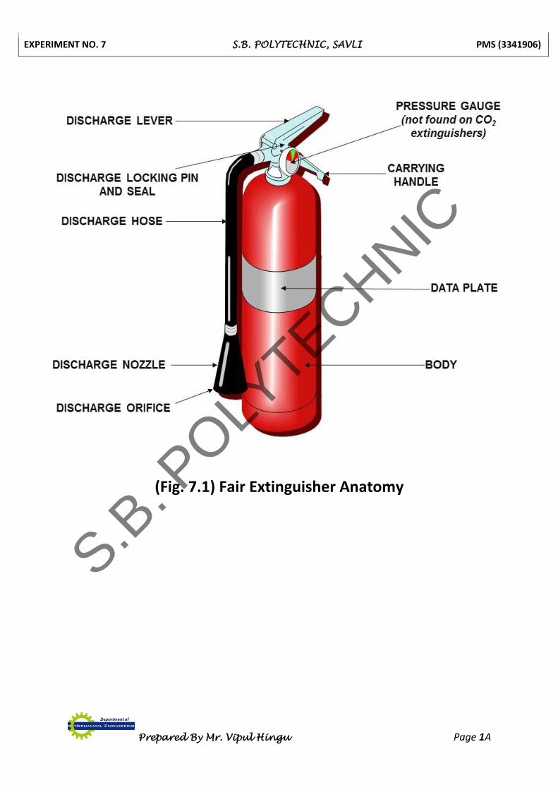
(Fig. 7.1) Fair Extinguisher Anatomy
S.B. P
OLYTECHNIC
EXPERIMENT NO. 7 S.B. POLYTECHNIC, SAVLI PMS (3341906)
Prepared By Mr. Vipul Hingu Page 2 of 4
Fire drills
Fire drills in order should be displaced on all sections notice boards and on all fire
points to make familiar to all person.
Points in order
1. Sounding the alarm
2. Informing the fire brigade
3. Evacuation of the premises
4. Shape of fire assembly
5. rope-call
6. Fire fighting pending
Fire exits
Fire exits and escapes routs should be clearly marked and must be kept free from obstacles.
Fire Fighting Equipment
Fire extinguisher
Water and Foam
Water and Foam fire extinguishers extinguish the fire by taking away the heat
element of the fire triangle. Foam agents also separate the oxygen element from the
other elements.
Water extinguishers are for Class A fires only - they should not be used on
Class B or C fires. The discharge stream could spread the flammable liquid in a Class
B fire or could create a shock hazard on a Class C fire.
Carbon Dioxide
Carbon Dioxide fire extinguishers extinguish fire by taking away the oxygen
element of the fire triangle and also be removing the heat with a very cold discharge.
Carbon dioxide can be used on Class B & C fires. They are usually ineffective
on Class A fires.
Dry Chemical
Dry Chemical fire extinguishers extinguish the fire primarily by interrupting
the chemical reaction of the fire triangle.
Today's most widely used type of fire extinguisher is the multipurpose dry
chemical that is effective on Class A, B, and C fires. This agent also works by creating
a barrier between the oxygen element and the fuel element on Class A fires.
S.B. P
OLYTECHNIC
EXPERIMENT NO. 7 S.B. POLYTECHNIC, SAVLI PMS (3341906)
Prepared By Mr. Vipul Hingu Page 2A
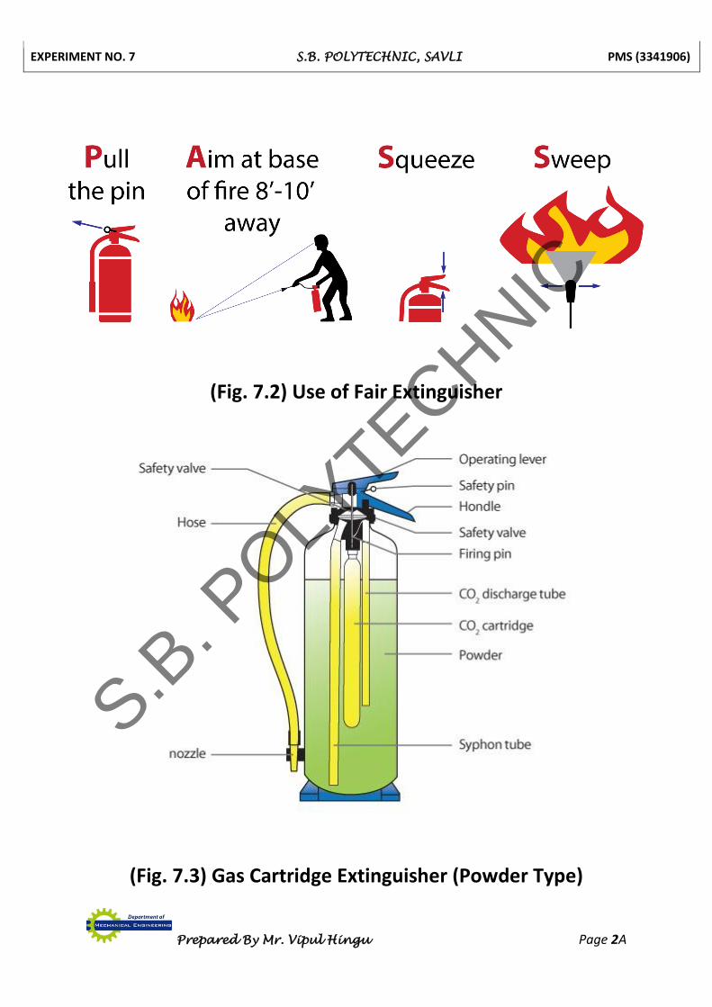
(Fig. 7.2) Use of Fair Extinguisher
(Fig. 7.3) Gas Cartridge Extinguisher (Powder Type)
S.B. P
OLYTECHNIC
EXPERIMENT NO. 7 S.B. POLYTECHNIC, SAVLI PMS (3341906)
Prepared By Mr. Vipul Hingu Page 3 of 4
Ordinary dry chemical is for Class B & C fires only. It is important to use the
correct extinguisher for the type of fuel! Using the incorrect agent can allow the fire
to re-ignite after apparently being extinguished successfully.
Wet Chemical
Wet Chemical is a new agent that extinguishes the fire by removing the heat
of the fire triangle and prevents re-ignition by creating a barrier between the oxygen
and fuel elements.
Wet chemical of Class K extinguishers were developed for modern, high
efficiency deep fat fryers in commercial cooking operations. Some may also be used
on Class A fires in commercial kitchens.
Clean Agent
Halogenated or Clean Agent extinguishers include the halon agents as well as
the newer and less ozone depleting halocarbon agents. They extinguish the fire by
interrupting the chemical reaction of the fire triangle.
Clean agent extinguishers are primarily for Class B & C fires. Some larger
clean agent extinguishers can be used on Class A, B, and C fires.
Dry Powder
Dry Powder extinguishers are similar to dry chemical except that they
extinguish the fire by separating the fuel from the oxygen element or by removing
the heat element of the fire triangle.
However, dry powder extinguishers are for Class D or combustible metal
fires, only. They are ineffective on all other classes of fires.
Water Mist
Water Mist extinguishers are a recent development that extinguish the fire
by taking away the heat element of the fire triangle. They are an alternative to the
clean agent extinguishers where contamination is a concern.
Water mist extinguishers are primarily for Class A fires, although they are
safe for use on Class C fires as well.
Cartridge Operated Dry Chemical
Cartridge Operated Dry Chemical fire extinguishers extinguish the fire
primarily by interrupting the chemical reaction of the fire triangle.
Like the stored pressure dry chemical extinguishers, the multipurpose dry
chemical is effective on Class A, B, and C fires. This agent also works by creating a
barrier between the oxygen element and the fuel element on Class A fires.
Ordinary dry chemical is for Class B & C fires only. It is important to use the
correct extinguisher for the type of fuel! Using the incorrect agent can allow the fire
to re-ignite after apparently being extinguished successfully.
S.B. P
OLYTECHNIC
EXPERIMENT NO. 7 S.B. POLYTECHNIC, SAVLI PMS (3341906)
Prepared By Mr. Vipul Hingu Page 4 of 4
Fire Extinguisher Use
It is important to know the locations and the types of extinguishers in your
workplace prior to actually using one.
Fire extinguishers can be heavy, so it's a good idea to practice picking up and holding
an extinguisher to get an idea of the weight and feel.
Take time to read the operating instructions and warnings found on the fire
extinguisher label. Not all fire extinguishers look alike.
Practice releasing the discharge hose or horn and aiming it at the base of an
imagined fire. Do not pull the pin or squeeze the lever. This will break the extinguisher seal
and cause it to lose pressure.
When it is time to use the extinguisher on a fire, just remember PASS!
Pull the pin.
Aim the nozzle or hose at the base of the fire from the recommended safe distance.
Squeeze the operating lever to discharge the fire extinguishing agent.
Starting at the recommended distance, Sweep the nozzle or hose from side to side until
the fire is out. Move forward or around the fire area as the fire diminishes. Watch the area
in case of re-ignition.
S.B. P
OLYTECHNIC

EXPERIMENT NO. 8 S.B. POLYTECHNIC, SAVLI PMS (3341906)
Prepared By Mr. Vipul Hingu Page 1 of 3
EXPERIMENT NO. 8
AIM: - To Prepare test Chart of Newly Installed Machine.
Test Chart For LATHE MACHINE:-
No. Test Item Allowable limit for defect
1. 2. 3. 4. 5. 6. 7. 8. 9. 10. 11. 12. 13. 14. 15. 16. 17 18.
Longitudinal levelling of machine. Transverse levelling of machine. Straightness of saddle travel Alignment of both the centres in vertical plane. Parallelism of main spindle and saddle movement. Parallelism of top slide with main spindle in vertical plane. Running & Slip defect of main spindle Running defect of head stock centre Parallelism of head stock guide and carriage. Accuracy of cylindrical turning. Lead screw bearing alignment. Accuracy of lead screw pitch Axial slip of head screw Alignment of lead screw & split-nut Accuracy of machine in circular working Accuracy of facing work Accuracy of thread cutting Parallelism of tail stock sleeve and saddle movement True running of head stock centre
0.02 mm/meter for front guide way 0.01 mm/meter for rear guide way. 0.02 mm/m 0.02mm/m length of mandrel 0.02mm 0.02mm/300mm 0.03mm/100mm 0.01mm 0.01mm 0.03mm to 0.04mm 0.02mm/300mm 0.15mm 0.03mm/300mm distance spacing between two thread 0.01mm in all direction 0.15mm 0.01mm 0.02mm 0.02mm/50mm length 0.01mm 0.01mm
S.B. P
OLYTECHNIC
EXPERIMENT NO. 8 S.B. POLYTECHNIC, SAVLI PMS (3341906)
Prepared By Mr. Vipul Hingu Page 2 of 3
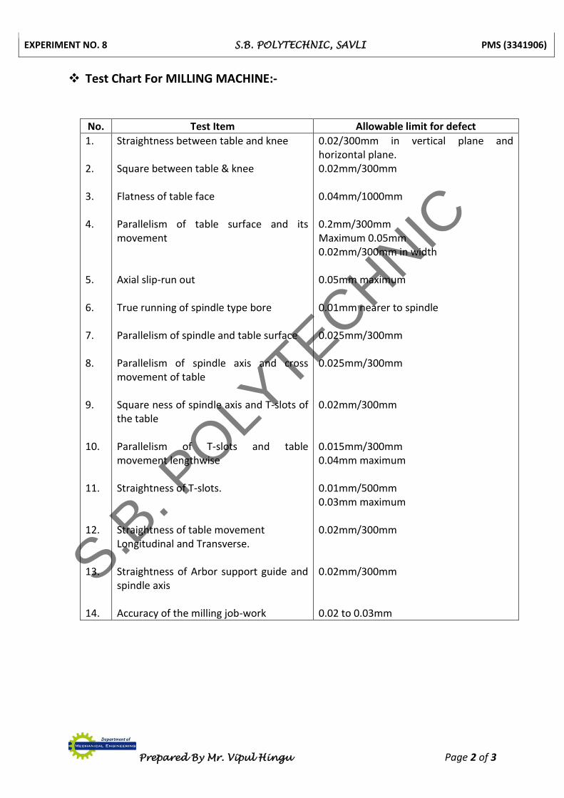
Test Chart For MILLING MACHINE:- No. Test Item Allowable limit for defect
1. 2. 3. 4. 5. 6. 7. 8. 9. 10. 11. 12. 13. 14.
Straightness between table and knee Square between table & knee Flatness of table face Parallelism of table surface and its movement Axial slip-run out True running of spindle type bore Parallelism of spindle and table surface Parallelism of spindle axis and cross movement of table Square ness of spindle axis and T-slots of the table Parallelism of T-slots and table movement lengthwise Straightness of T-slots. Straightness of table movement Longitudinal and Transverse. Straightness of Arbor support guide and spindle axis Accuracy of the milling job-work
0.02/300mm in vertical plane and horizontal plane. 0.02mm/300mm 0.04mm/1000mm 0.2mm/300mm Maximum 0.05mm 0.02mm/300mm in width 0.05mm maximum 0.01mm nearer to spindle 0.025mm/300mm 0.025mm/300mm 0.02mm/300mm 0.015mm/300mm 0.04mm maximum 0.01mm/500mm 0.03mm maximum 0.02mm/300mm 0.02mm/300mm 0.02 to 0.03mm
S.B. P
OLYTECHNIC
EXPERIMENT NO. 8 S.B. POLYTECHNIC, SAVLI PMS (3341906)
Prepared By Mr. Vipul Hingu Page 3 of 3
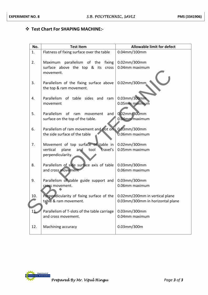
Test Chart For SHAPING MACHINE:-
No. Test Item Allowable limit for defect
1. 2. 3. 4. 5. 6. 7. 8. 9. 10. 11. 12.
Flatness of fixing surface over the table Maximum parallelism of the fixing surface above the top & its cross movement. Parallelism of the fixing surface above the top & ram movement. Parallelism of table sides and ram movement Parallelism of ram movement and surface on the top of the table. Parallelism of ram movement and slot on the side surface of the table Movement of top surface of table in vertical plane and tool travel’s perpendicularity. Parallelism of side surface axis of table and cross movement Parallelism of table guide support and cross movement. Perpendicularity of fixing surface of the table & ram movement. Parallelism of T-slots of the table carriage and cross movement. Machining accuracy
0.04mm/100mm 0.02mm/300mm 0.04mm maximum 0.02mm/300mm 0.03mm/300mm 0.05mm maximum 0.02mm/300mm 0.04mm maximum 0.03mm/300mm 0.06mm maximum 0.02mm/300mm 0.05mm maximum 0.03mm/300mm 0.06mm maximum 0.03mm/300mm 0.06mm maximum 0.02mm/200mm in vertical plane 0.03mm/300mm in horizontal plane 0.03mm/300mm 0.04mm maximum 0.03mm/300m
S.B. P
OLYTECHNIC