3341904 cad lab_manual_prepared by vipul hingu
41
LAB MANUAL Prepared By Mr. Vipul Hingu B.E. (Mech.) COMPUTER AIDED DESIGN SUBJECT CODE :- 3341904 S.B. POLYTECHNIC
-
Upload
vipul-hingu -
Category
Engineering
-
view
203 -
download
1
Transcript of 3341904 cad lab_manual_prepared by vipul hingu

LAB
MANUAL
Prepared By
Mr. Vipul Hingu
B.E. (Mech.)
COMPUTER AIDED DESIGN
SUBJECT CODE :- 3341904
S.B. P
OLYTECHNIC
LAB PRACTICAL LIST CAD (3341904)
Prepared By Mr. Vipul Hingu
LAB PRACTICAL LIST
Practical No. Aim of Practical
1 Preparatory Activity
2 3D Solid Modeling-I
3 3D Surface Model
4 3D Solid Modeling-III
5 3D Solid Modeling-III
S.B. P
OLYTECHNIC
EXPERIMENT NO. 1 S.B. POLYTECHNIC, SAVLI CAD (3341904)
Prepared By Mr. Vipul Hingu Page 1 of 7
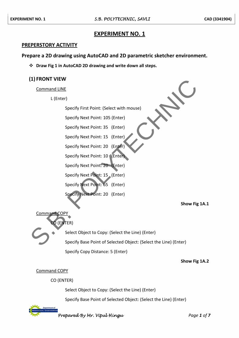
EXPERIMENT NO. 1
PREPERSTORY ACTIVITY
Prepare a 2D drawing using AutoCAD and 2D parametric sketcher environment.
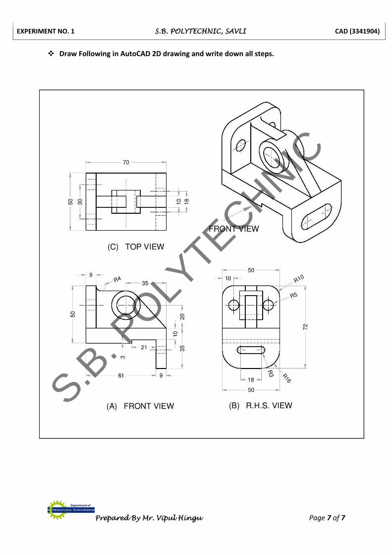
Draw Fig 1 in AutoCAD 2D drawing and write down all steps.
(1) FRONT VIEW
Command LINE
L (Enter)
Specify First Point: (Select with mouse)
Specify Next Point: 105 (Enter)
Specify Next Point: 35 (Enter)
Specify Next Point: 15 (Enter)
Specify Next Point: 20 (Enter)
Specify Next Point: 10 (Enter)
Specify Next Point: 20 (Enter)
Specify Next Point: 15 (Enter)
Specify Next Point: 65 (Enter)
Specify Next Point: 20 (Enter)
Show Fig 1A.1
Command COPY
CO (ENTER)
Select Object to Copy: (Select the Line) (Enter)
Specify Base Point of Selected Object: (Select the Line) (Enter)
Specify Copy Distance: 5 (Enter)
Show Fig 1A.2
Command COPY
CO (ENTER)
Select Object to Copy: (Select the Line) (Enter)
Specify Base Point of Selected Object: (Select the Line) (Enter)
S.B. P
OLYTECHNIC

EXPERIMENT NO. 1 S.B. POLYTECHNIC, SAVLI CAD (3341904)
Prepared By Mr. Vipul Hingu Page 1A
Fig. No. 1
S.B. P
OLYTECHNIC
EXPERIMENT NO. 1 S.B. POLYTECHNIC, SAVLI CAD (3341904)
Prepared By Mr. Vipul Hingu Page 2 of 7
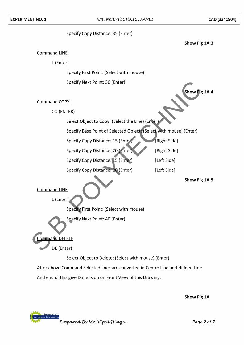
Specify Copy Distance: 35 (Enter)
Show Fig 1A.3
Command LINE
L (Enter)
Specify First Point: (Select with mouse)
Specify Next Point: 30 (Enter)
Show Fig 1A.4
Command COPY
CO (ENTER)
Select Object to Copy: (Select the Line) (Enter)
Specify Base Point of Selected Object: (Select with mouse) (Enter)
Specify Copy Distance: 15 (Enter) [Right Side]
Specify Copy Distance: 20 (Enter) [Right Side]
Specify Copy Distance: 15 (Enter) [Left Side]
Specify Copy Distance: 20 (Enter) [Left Side]
Show Fig 1A.5
Command LINE
L (Enter)
Specify First Point: (Select with mouse)
Specify Next Point: 40 (Enter)
Command DELETE
DE (Enter)
Select Object to Delete: (Select with mouse) (Enter)
After above Command Selected lines are converted in Centre Line and Hidden Line
And end of this give Dimension on Front View of this Drawing.
Show Fig 1A
S.B. P
OLYTECHNIC

EXPERIMENT NO. 1 S.B. POLYTECHNIC, SAVLI CAD (3341904)
Prepared By Mr. Vipul Hingu Page 2A
S.B. P
OLYTECHNIC
EXPERIMENT NO. 1 S.B. POLYTECHNIC, SAVLI CAD (3341904)
Prepared By Mr. Vipul Hingu Page 3 of 7
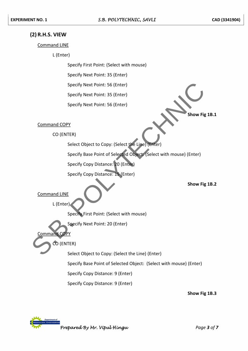
(2) R.H.S. VIEW
Command LINE
L (Enter)
Specify First Point: (Select with mouse)
Specify Next Point: 35 (Enter)
Specify Next Point: 56 (Enter)
Specify Next Point: 35 (Enter)
Specify Next Point: 56 (Enter)
Show Fig 1B.1
Command COPY
CO (ENTER)
Select Object to Copy: (Select the Line) (Enter)
Specify Base Point of Selected Object: (Select with mouse) (Enter)
Specify Copy Distance: 20 (Enter)
Specify Copy Distance: 15 (Enter)
Show Fig 1B.2
Command LINE
L (Enter)
Specify First Point: (Select with mouse)
Specify Next Point: 20 (Enter)
Command COPY
CO (ENTER)
Select Object to Copy: (Select the Line) (Enter)
Specify Base Point of Selected Object: (Select with mouse) (Enter)
Specify Copy Distance: 9 (Enter)
Specify Copy Distance: 9 (Enter)
Show Fig 1B.3
S.B. P
OLYTECHNIC

EXPERIMENT NO. 1 S.B. POLYTECHNIC, SAVLI CAD (3341904)
Prepared By Mr. Vipul Hingu Page 3A
S.B. P
OLYTECHNIC
EXPERIMENT NO. 1 S.B. POLYTECHNIC, SAVLI CAD (3341904)
Prepared By Mr. Vipul Hingu Page 4 of 7
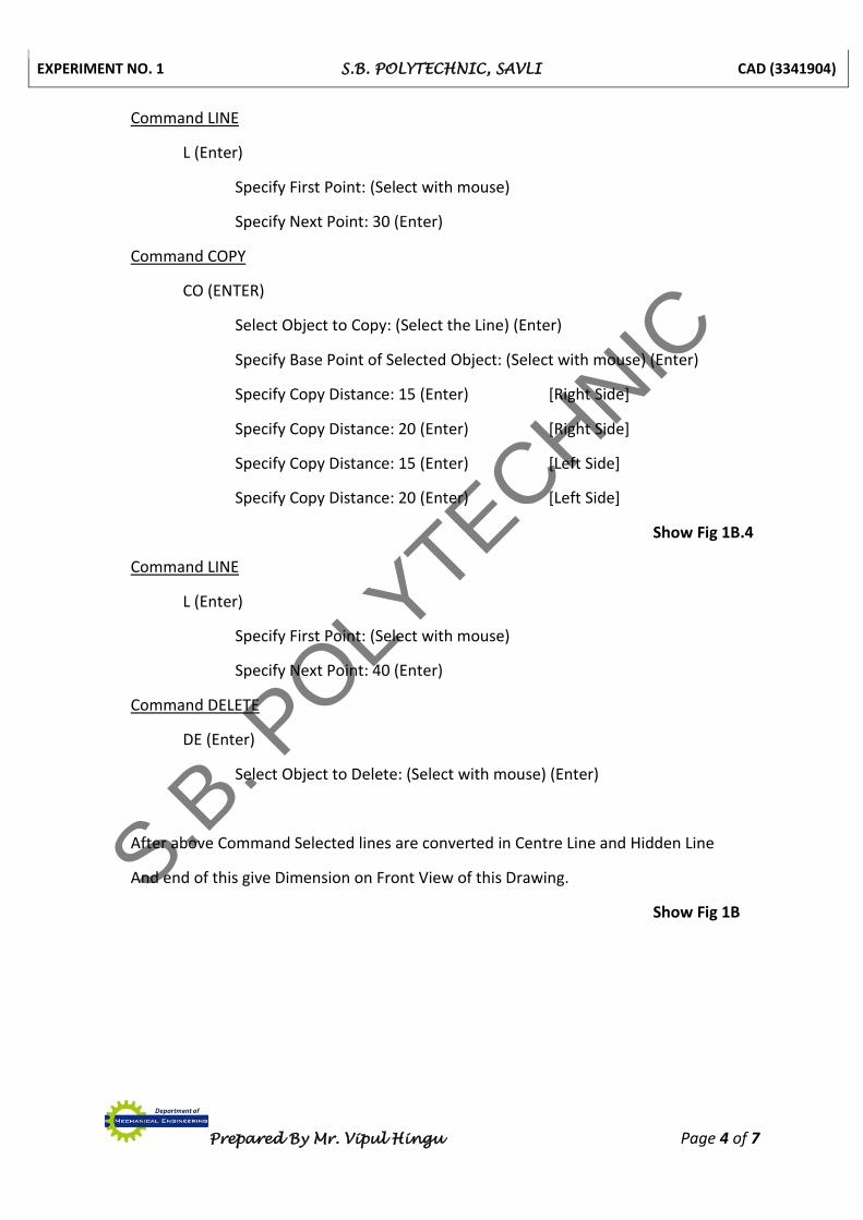
Command LINE
L (Enter)
Specify First Point: (Select with mouse)
Specify Next Point: 30 (Enter)
Command COPY
CO (ENTER)
Select Object to Copy: (Select the Line) (Enter)
Specify Base Point of Selected Object: (Select with mouse) (Enter)
Specify Copy Distance: 15 (Enter) [Right Side]
Specify Copy Distance: 20 (Enter) [Right Side]
Specify Copy Distance: 15 (Enter) [Left Side]
Specify Copy Distance: 20 (Enter) [Left Side]
Show Fig 1B.4
Command LINE
L (Enter)
Specify First Point: (Select with mouse)
Specify Next Point: 40 (Enter)
Command DELETE
DE (Enter)
Select Object to Delete: (Select with mouse) (Enter)
After above Command Selected lines are converted in Centre Line and Hidden Line
And end of this give Dimension on Front View of this Drawing.
Show Fig 1B
S.B. P
OLYTECHNIC
EXPERIMENT NO. 1 S.B. POLYTECHNIC, SAVLI CAD (3341904)
Prepared By Mr. Vipul Hingu Page 4A
S.B. P
OLYTECHNIC
EXPERIMENT NO. 1 S.B. POLYTECHNIC, SAVLI CAD (3341904)
Prepared By Mr. Vipul Hingu Page 5 of 7
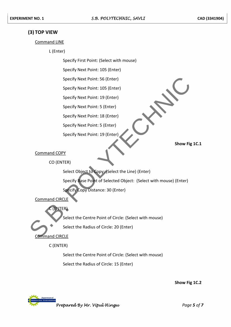
(3) TOP VIEW
Command LINE
L (Enter)
Specify First Point: (Select with mouse)
Specify Next Point: 105 (Enter)
Specify Next Point: 56 (Enter)
Specify Next Point: 105 (Enter)
Specify Next Point: 19 (Enter)
Specify Next Point: 5 (Enter)
Specify Next Point: 18 (Enter)
Specify Next Point: 5 (Enter)
Specify Next Point: 19 (Enter)
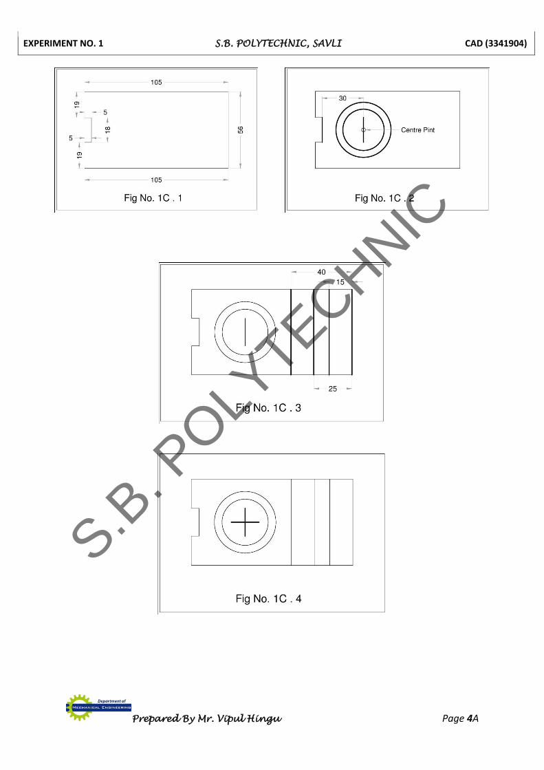
Show Fig 1C.1
Command COPY
CO (ENTER)
Select Object to Copy: (Select the Line) (Enter)
Specify Base Point of Selected Object: (Select with mouse) (Enter)
Specify Copy Distance: 30 (Enter)
Command CIRCLE
C (ENTER)
Select the Centre Point of Circle: (Select with mouse)
Select the Radius of Circle: 20 (Enter)
Command CIRCLE
C (ENTER)
Select the Centre Point of Circle: (Select with mouse)
Select the Radius of Circle: 15 (Enter)
Show Fig 1C.2
S.B. P
OLYTECHNIC
EXPERIMENT NO. 1 S.B. POLYTECHNIC, SAVLI CAD (3341904)
Prepared By Mr. Vipul Hingu Page 6 of 7
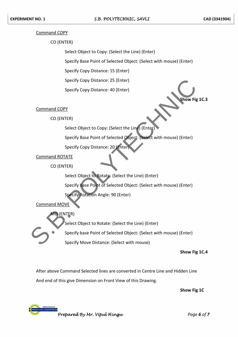
Command COPY
CO (ENTER)
Select Object to Copy: (Select the Line) (Enter)
Specify Base Point of Selected Object: (Select with mouse) (Enter)
Specify Copy Distance: 15 (Enter)
Specify Copy Distance: 25 (Enter)
Specify Copy Distance: 40 (Enter)
Show Fig 1C.3
Command COPY
CO (ENTER)
Select Object to Copy: (Select the Line) (Enter)
Specify Base Point of Selected Object: (Select with mouse) (Enter)
Specify Copy Distance: 20 (Enter)
Command ROTATE
CO (ENTER)
Select Object to Rotate: (Select the Line) (Enter)
Specify base Point of Selected Object: (Select with mouse) (Enter)
Specify Rotation Angle: 90 (Enter)
Command MOVE
MO (ENTER)
Select Object to Rotate: (Select the Line) (Enter)
Specify base Point of Selected Object: (Select with mouse) (Enter)
Specify Move Distance: (Select with mouse)
Show Fig 1C.4
After above Command Selected lines are converted in Centre Line and Hidden Line
And end of this give Dimension on Front View of this Drawing.
Show Fig 1C
S.B. P
OLYTECHNIC
EXPERIMENT NO. 1 S.B. POLYTECHNIC, SAVLI CAD (3341904)
Prepared By Mr. Vipul Hingu Page 7 of 7
Draw Following in AutoCAD 2D drawing and write down all steps.
S.B. P
OLYTECHNIC
EXPERIMENT NO. 2 S.B. POLYTECHNIC, SAVLI CAD (3341904)
Prepared By Mr. Vipul Hingu Page 1 of 5
EXPERIMENT NO. 2
3D SOLID MODELING – I (AUTOCAD)
Prepare 3D Solid Model using AutoCAD.
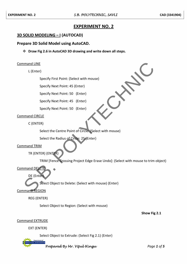
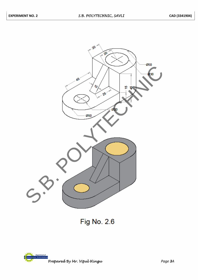
Draw Fig 2.6 in AutoCAD 3D drawing and write down all steps.
Command LINE
L (Enter)
Specify First Point: (Select with mouse)
Specify Next Point: 45 (Enter)
Specify Next Point: 50 (Enter)
Specify Next Point: 45 (Enter)
Specify Next Point: 50 (Enter)
Command CIRCLE
C (ENTER)
Select the Centre Point of Circle: (Select with mouse)
Select the Radius of Circle: 25 (Enter)
Command TRIM
TR (ENTER) (ENTER)
TRIM [Fence Crossing Project Edge Erase Undo]: (Select with mouse to trim object)
Command DELETE
DE (Enter)
Select Object to Delete: (Select with mouse) (Enter)
Command REGION
REG (ENTER)
Select Object to Region: (Select with mouse)
Show Fig 2.1
Command EXTRUDE
EXT (ENTER)
Select Object to Extrude: (Select Fig 2.1) (Enter)
S.B. P
OLYTECHNIC

EXPERIMENT NO. 2 S.B. POLYTECHNIC, SAVLI CAD (3341904)
Prepared By Mr. Vipul Hingu Page 1A
S.B. P
OLYTECHNIC

EXPERIMENT NO. 2 S.B. POLYTECHNIC, SAVLI CAD (3341904)
Prepared By Mr. Vipul Hingu Page 2 of 5
Specify Height of Extrusion: 15 (Enter)
Show Fig 2.2
Command CYLINDER
CYL (ENTER)
Select Centre Point: (Select with mouse)
Specify Base Radius: 10 (Enter)
Specify Height: 15 (Enter)
Command SUBTRACT
SU (ENTER)
Select Main Object: (Select Cylinder with mouse) (Enter)
Select Object to Subtract: (Select Base with mouse) (Enter)
Show Fig 2.3
Command LINE
L (Enter)
Specify First Point: (Select with mouse)
Specify Next Point: 50 (Enter)
Specify Next Point: 20 (Enter)
Specify Next Point: 50 (Enter)
Specify Next Point: 20 (Enter)
Command CIRCLE
C (ENTER)
Select the Centre Point of Circle: (Select with mouse)
Select the Radius of Circle: 25 (Enter)
Command TRIM
TR (ENTER) (ENTER)
TRIM [Fence Crossing Project Edge eRase Undo]: (Select with mouse to trim object)
Command DELETE
DE (Enter)
Select Object to Delete: (Select with mouse) (Enter)
S.B. P
OLYTECHNIC
EXPERIMENT NO. 2 S.B. POLYTECHNIC, SAVLI CAD (3341904)
Prepared By Mr. Vipul Hingu Page 2A
S.B. P
OLYTECHNIC
EXPERIMENT NO. 2 S.B. POLYTECHNIC, SAVLI CAD (3341904)
Prepared By Mr. Vipul Hingu Page 3 of 5
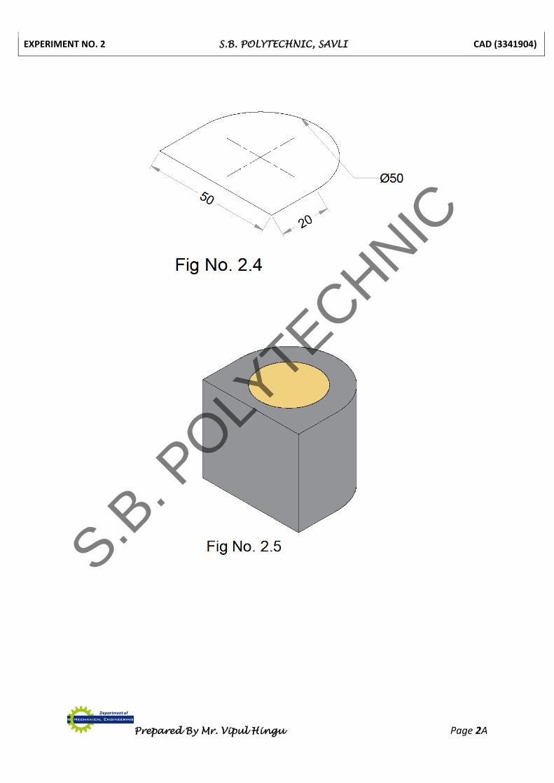
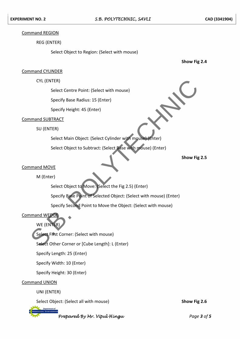
Command REGION
REG (ENTER)
Select Object to Region: (Select with mouse)
Show Fig 2.4
Command CYLINDER
CYL (ENTER)
Select Centre Point: (Select with mouse)
Specify Base Radius: 15 (Enter)
Specify Height: 45 (Enter)
Command SUBTRACT
SU (ENTER)
Select Main Object: (Select Cylinder with mouse) (Enter)
Select Object to Subtract: (Select Base with mouse) (Enter)
Show Fig 2.5
Command MOVE
M (Enter)
Select Object to Move: (Select the Fig 2.5) (Enter)
Specify Base Point of Selected Object: (Select with mouse) (Enter)
Specify Second Point to Move the Object: (Select with mouse)
Command WEDGE
WE (ENTER)
Select First Corner: (Select with mouse)
Select Other Corner or [Cube Length]: L (Enter)
Specify Length: 25 (Enter)
Specify Width: 10 (Enter)
Specify Height: 30 (Enter)
Command UNION
UNI (ENTER)
Select Object: (Select all with mouse) Show Fig 2.6
S.B. P
OLYTECHNIC
EXPERIMENT NO. 2 S.B. POLYTECHNIC, SAVLI CAD (3341904)
Prepared By Mr. Vipul Hingu Page 3A
S.B. P
OLYTECHNIC
EXPERIMENT NO. 2 S.B. POLYTECHNIC, SAVLI CAD (3341904)
Prepared By Mr. Vipul Hingu Page 4 of 5
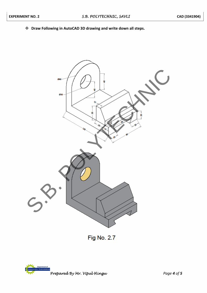
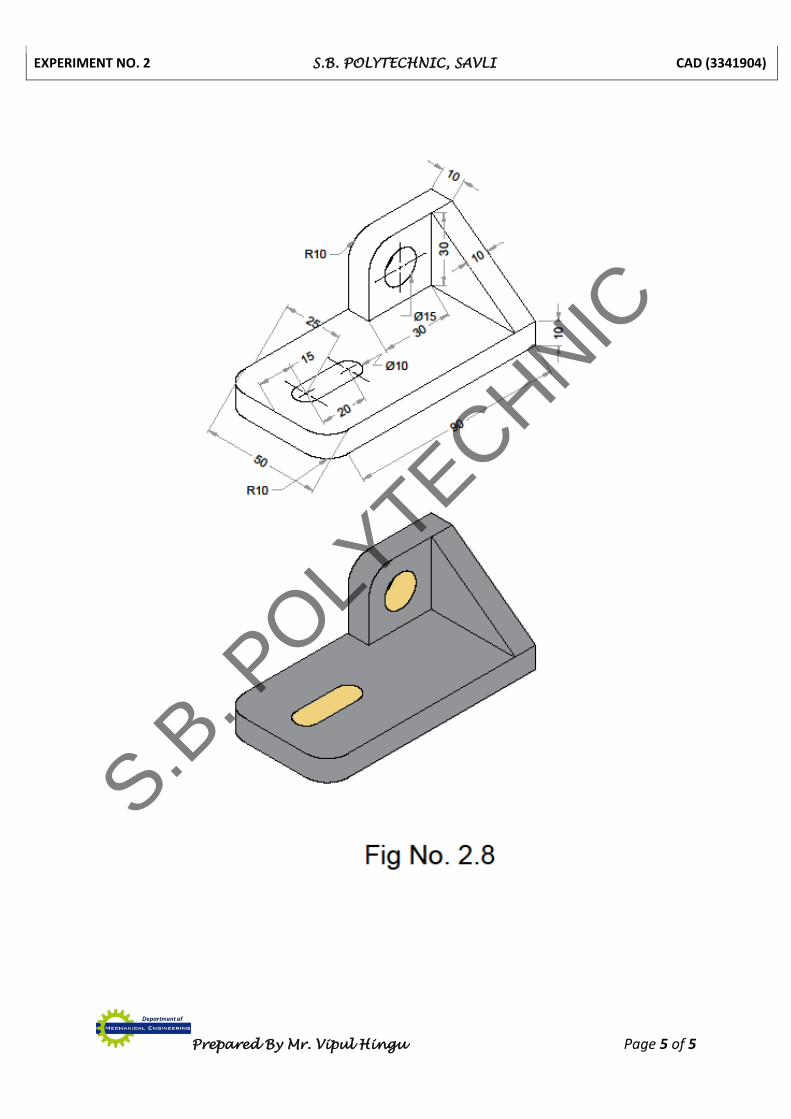
Draw Following in AutoCAD 3D drawing and write down all steps.
S.B. P
OLYTECHNIC
EXPERIMENT NO. 2 S.B. POLYTECHNIC, SAVLI CAD (3341904)
Prepared By Mr. Vipul Hingu Page 5 of 5
S.B. P
OLYTECHNIC
EXPERIMENT NO. 3 S.B. POLYTECHNIC, SAVLI CAD (3341904)
Prepared By Mr. Vipul Hingu Page 1 of 5
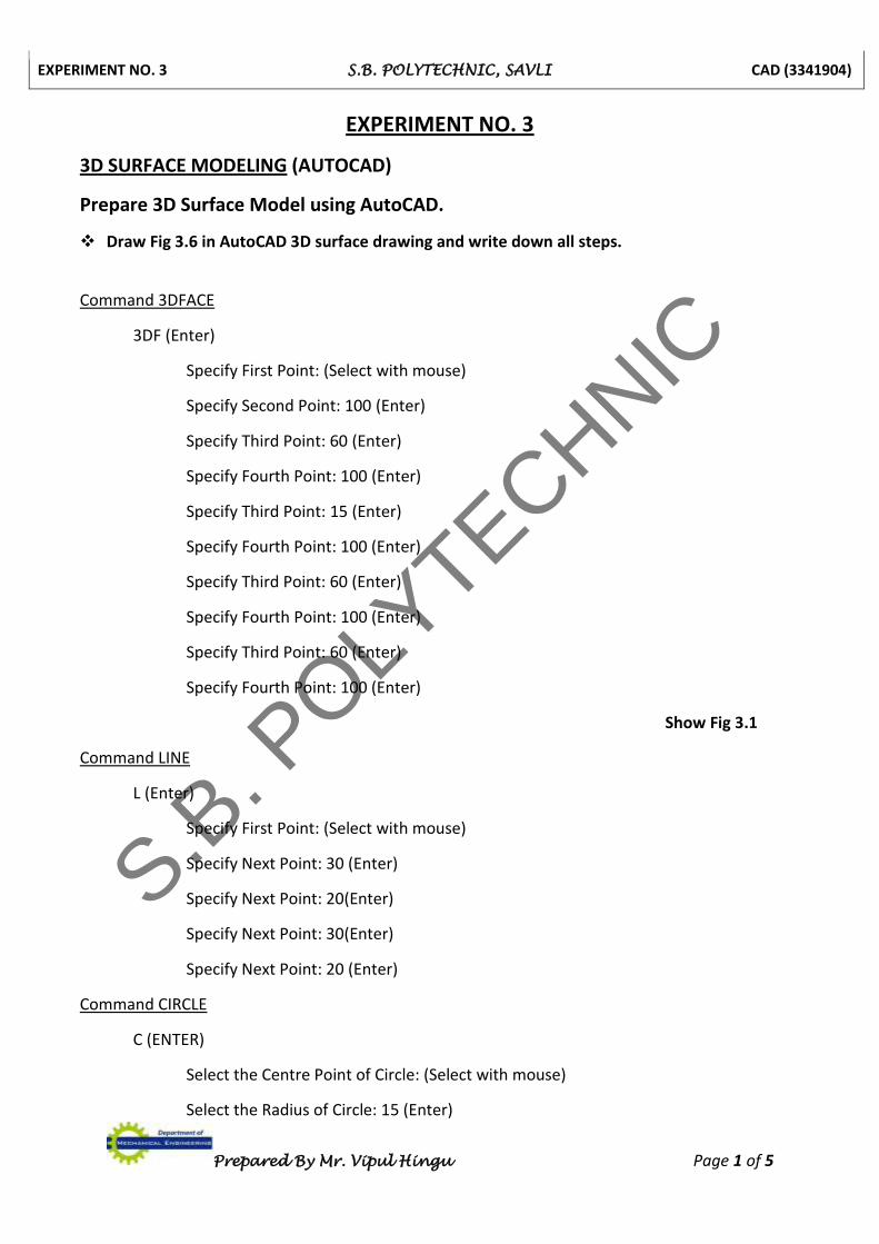
EXPERIMENT NO. 3
3D SURFACE MODELING (AUTOCAD)
Prepare 3D Surface Model using AutoCAD.
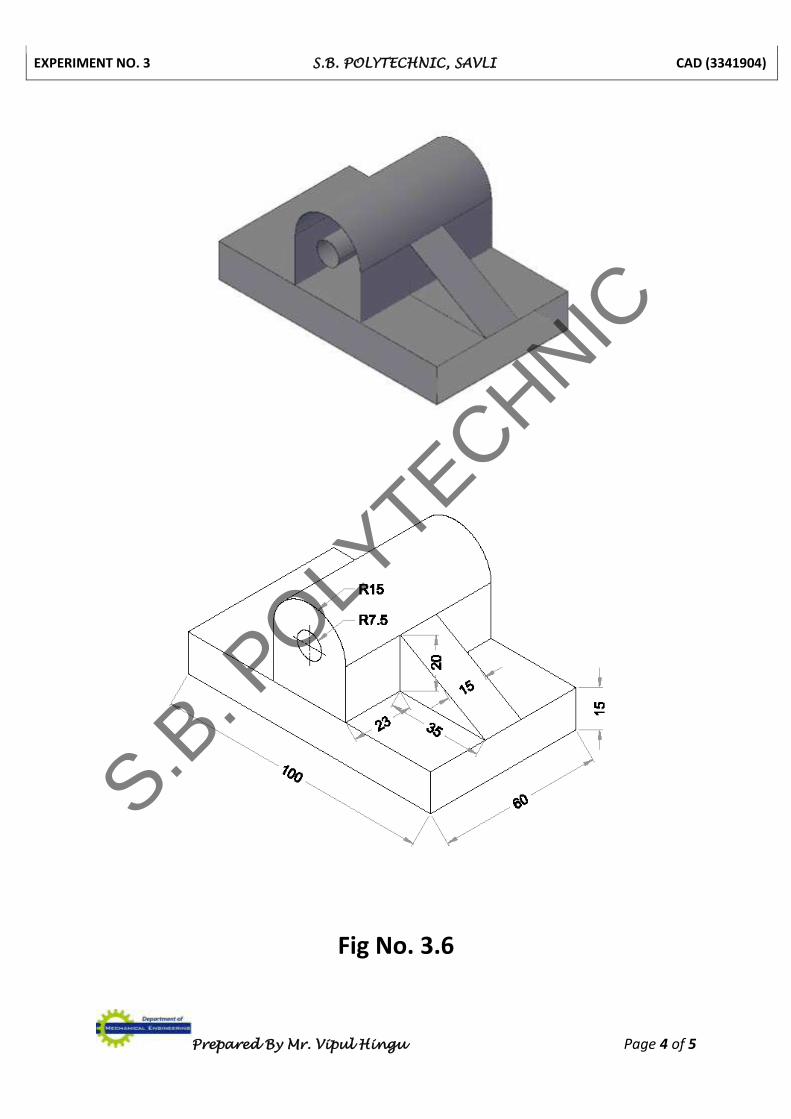
Draw Fig 3.6 in AutoCAD 3D surface drawing and write down all steps.
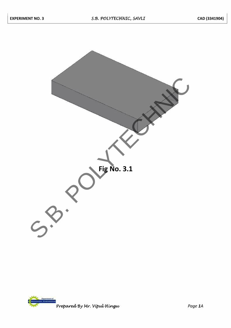
Command 3DFACE
3DF (Enter)
Specify First Point: (Select with mouse)
Specify Second Point: 100 (Enter)
Specify Third Point: 60 (Enter)
Specify Fourth Point: 100 (Enter)
Specify Third Point: 15 (Enter)
Specify Fourth Point: 100 (Enter)
Specify Third Point: 60 (Enter)
Specify Fourth Point: 100 (Enter)
Specify Third Point: 60 (Enter)
Specify Fourth Point: 100 (Enter)
Show Fig 3.1
Command LINE
L (Enter)
Specify First Point: (Select with mouse)
Specify Next Point: 30 (Enter)
Specify Next Point: 20(Enter)
Specify Next Point: 30(Enter)
Specify Next Point: 20 (Enter)
Command CIRCLE
C (ENTER)
Select the Centre Point of Circle: (Select with mouse)
Select the Radius of Circle: 15 (Enter)
S.B. P
OLYTECHNIC
EXPERIMENT NO. 3 S.B. POLYTECHNIC, SAVLI CAD (3341904)
Prepared By Mr. Vipul Hingu Page 1A
Fig No. 3.1
S.B. P
OLYTECHNIC
EXPERIMENT NO. 3 S.B. POLYTECHNIC, SAVLI CAD (3341904)
Prepared By Mr. Vipul Hingu Page 2 of 5
Command CIRCLE
C (ENTER)
Select the Centre Point of Circle: (Select with mouse)
Select the Radius of Circle: 5 (Enter)
Command TRIM
TR (ENTER) (ENTER)
TRIM [Fence Crossing Project Edge Erase Undo]: (Select with mouse to trim object)
Command DELETE
DE (Enter)
Select Object to Delete: (Select with mouse) (Enter)
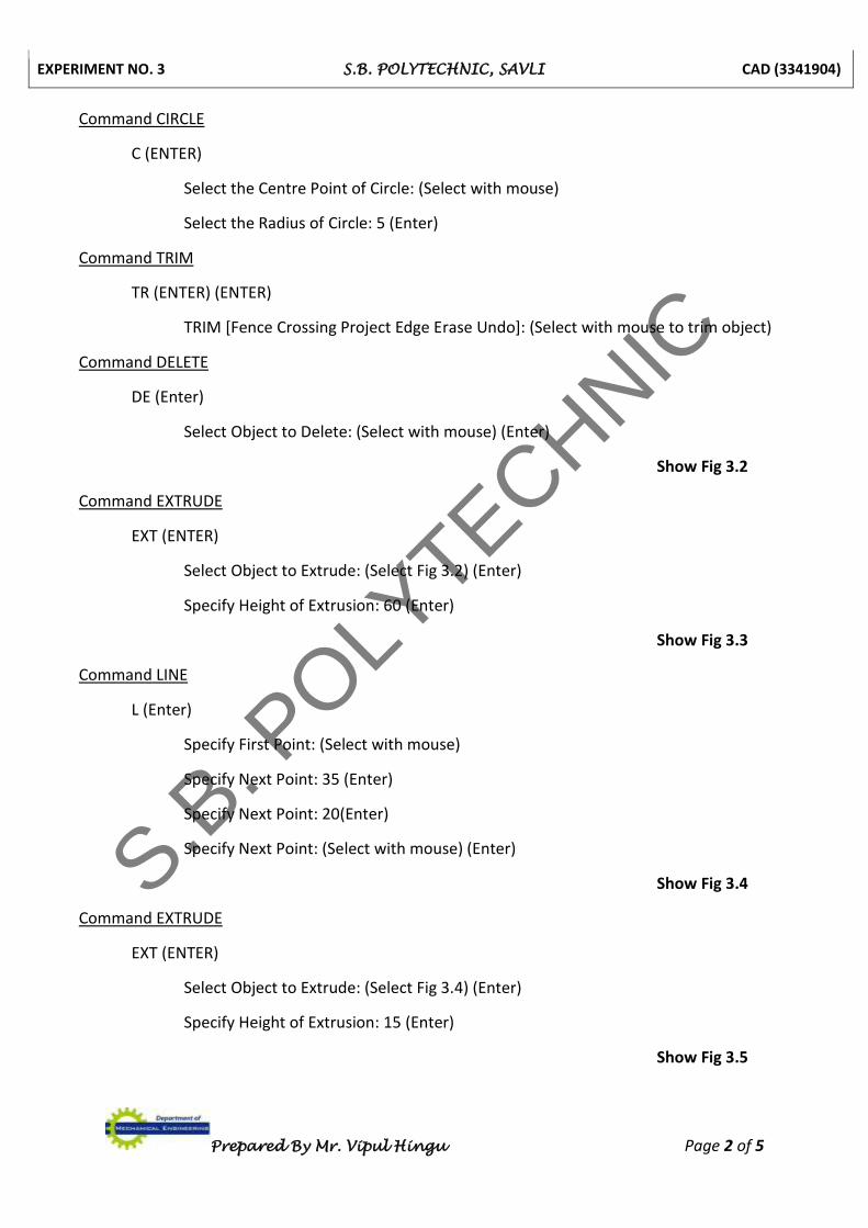
Show Fig 3.2
Command EXTRUDE
EXT (ENTER)
Select Object to Extrude: (Select Fig 3.2) (Enter)
Specify Height of Extrusion: 60 (Enter)
Show Fig 3.3
Command LINE
L (Enter)
Specify First Point: (Select with mouse)
Specify Next Point: 35 (Enter)
Specify Next Point: 20(Enter)
Specify Next Point: (Select with mouse) (Enter)
Show Fig 3.4
Command EXTRUDE
EXT (ENTER)
Select Object to Extrude: (Select Fig 3.4) (Enter)
Specify Height of Extrusion: 15 (Enter)
Show Fig 3.5
S.B. P
OLYTECHNIC
EXPERIMENT NO. 3 S.B. POLYTECHNIC, SAVLI CAD (3341904)
Prepared By Mr. Vipul Hingu Page 2A
Fig No. 3.3
S.B. P
OLYTECHNIC
EXPERIMENT NO. 3 S.B. POLYTECHNIC, SAVLI CAD (3341904)
Prepared By Mr. Vipul Hingu Page 3 of 5
Command MOVE
M (ENTER)
Select Object to Move: (Select the Fig 3.3) (Enter)
Specify Base Point of Selected Object: (Select with mouse) (Enter)
Specify Second Point to Move the Object: (Select with mouse)
Command MOVE
M (ENTER)
Select Object to Move: (Select the Fig 3.5) (Enter)
Specify Base Point of Selected Object: (Select with mouse) (Enter)
Specify Second Point to Move the Object: (Select with mouse)
Show Fig 3.6
S.B. P
OLYTECHNIC

EXPERIMENT NO. 3 S.B. POLYTECHNIC, SAVLI CAD (3341904)
Prepared By Mr. Vipul Hingu Page 3A
Fig No. 3.5
S.B. P
OLYTECHNIC
EXPERIMENT NO. 3 S.B. POLYTECHNIC, SAVLI CAD (3341904)
Prepared By Mr. Vipul Hingu Page 4 of 5
Fig No. 3.6
S.B. P
OLYTECHNIC
EXPERIMENT NO. 3 S.B. POLYTECHNIC, SAVLI CAD (3341904)
Prepared By Mr. Vipul Hingu Page 5 of 5
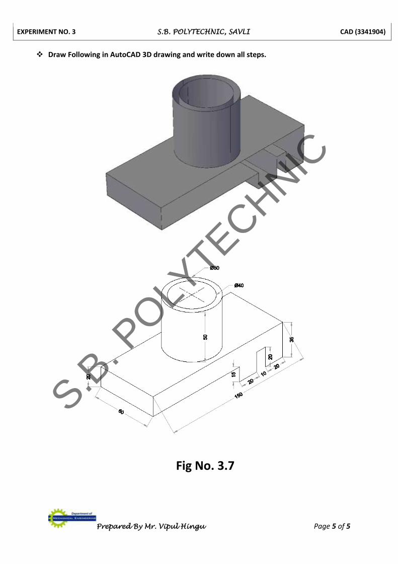
Draw Following in AutoCAD 3D drawing and write down all steps.
Fig No. 3.7
S.B. P
OLYTECHNIC
EXPERIMENT NO. 4 S.B. POLYTECHNIC, SAVLI CAD (3341904)
Prepared By Mr. Vipul Hingu Page 1 of 6
EXPERIMENT NO. 4
3D SOLID MODELING - II (AUTODESK INVENTOR)
Prepare 3D Model using Autodesk Inventor.
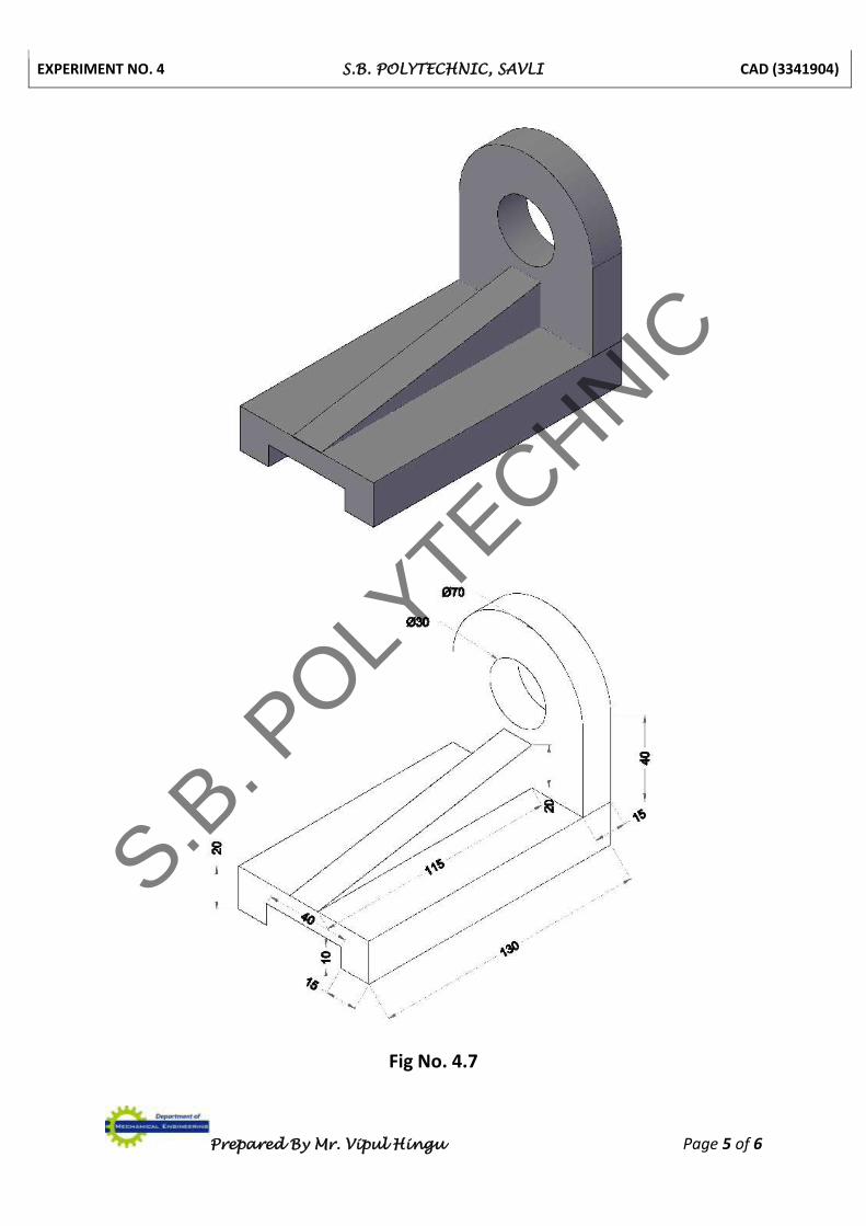
Draw Fig 4.7 in Autodesk Inventor and write down all steps.
STEP – 1
Open the Autodesk Inventor by double clicking the mouse, select part file.
STEP – 2
For creating new part click by mouse on 2D sketch Icon and select by mouse click XY Plane.
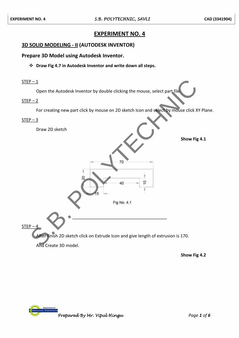
STEP – 3
Draw 2D sketch
Show Fig 4.1
STEP – 4
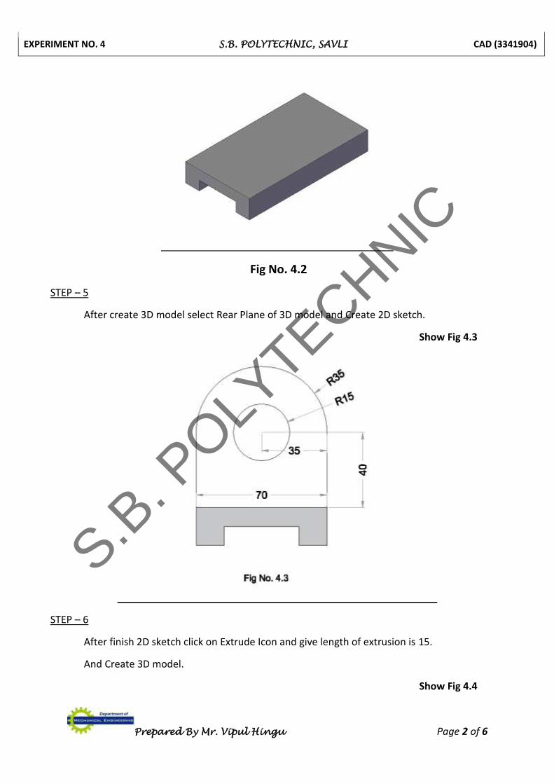
After finish 2D sketch click on Extrude Icon and give length of extrusion is 170.
And Create 3D model.
Show Fig 4.2
S.B. P
OLYTECHNIC
EXPERIMENT NO. 4 S.B. POLYTECHNIC, SAVLI CAD (3341904)
Prepared By Mr. Vipul Hingu Page 2 of 6
Fig No. 4.2
STEP – 5
After create 3D model select Rear Plane of 3D model and Create 2D sketch.
Show Fig 4.3
STEP – 6
After finish 2D sketch click on Extrude Icon and give length of extrusion is 15.
And Create 3D model.
Show Fig 4.4
S.B. P
OLYTECHNIC

EXPERIMENT NO. 4 S.B. POLYTECHNIC, SAVLI CAD (3341904)
Prepared By Mr. Vipul Hingu Page 3 of 6
Fig No. 4.4
STEP – 7
After create 3D model select Rear Plane of 3D model and Create 2D sketch.
STEP – 8
After finish 2D sketch click on Extrude Icon and give length of Extrude Cut is 15.
Show Fig 4.5
Fig No. 4.5
S.B. P
OLYTECHNIC
EXPERIMENT NO. 4 S.B. POLYTECHNIC, SAVLI CAD (3341904)
Prepared By Mr. Vipul Hingu Page 4 of 6
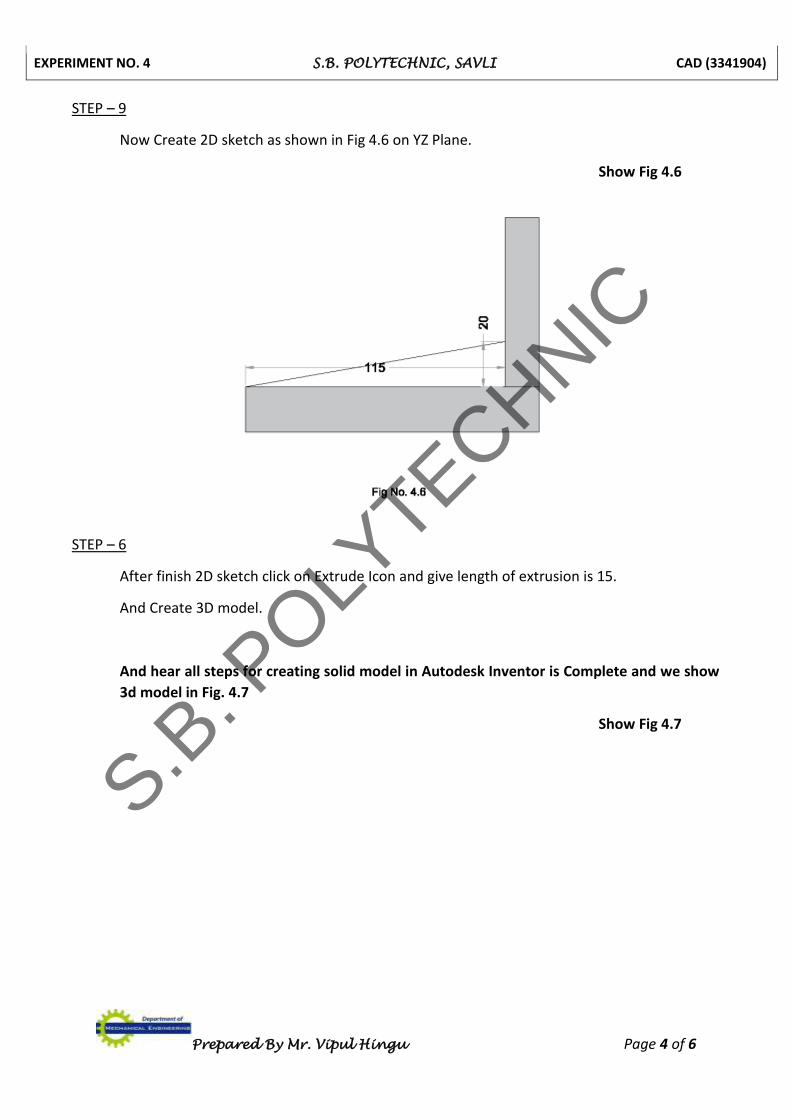
STEP – 9
Now Create 2D sketch as shown in Fig 4.6 on YZ Plane.
Show Fig 4.6
STEP – 6
After finish 2D sketch click on Extrude Icon and give length of extrusion is 15.
And Create 3D model.
And hear all steps for creating solid model in Autodesk Inventor is Complete and we show
3d model in Fig. 4.7
Show Fig 4.7
S.B. P
OLYTECHNIC
EXPERIMENT NO. 4 S.B. POLYTECHNIC, SAVLI CAD (3341904)
Prepared By Mr. Vipul Hingu Page 5 of 6
Fig No. 4.7
S.B. P
OLYTECHNIC
EXPERIMENT NO. 4 S.B. POLYTECHNIC, SAVLI CAD (3341904)
Prepared By Mr. Vipul Hingu Page 6 of 6
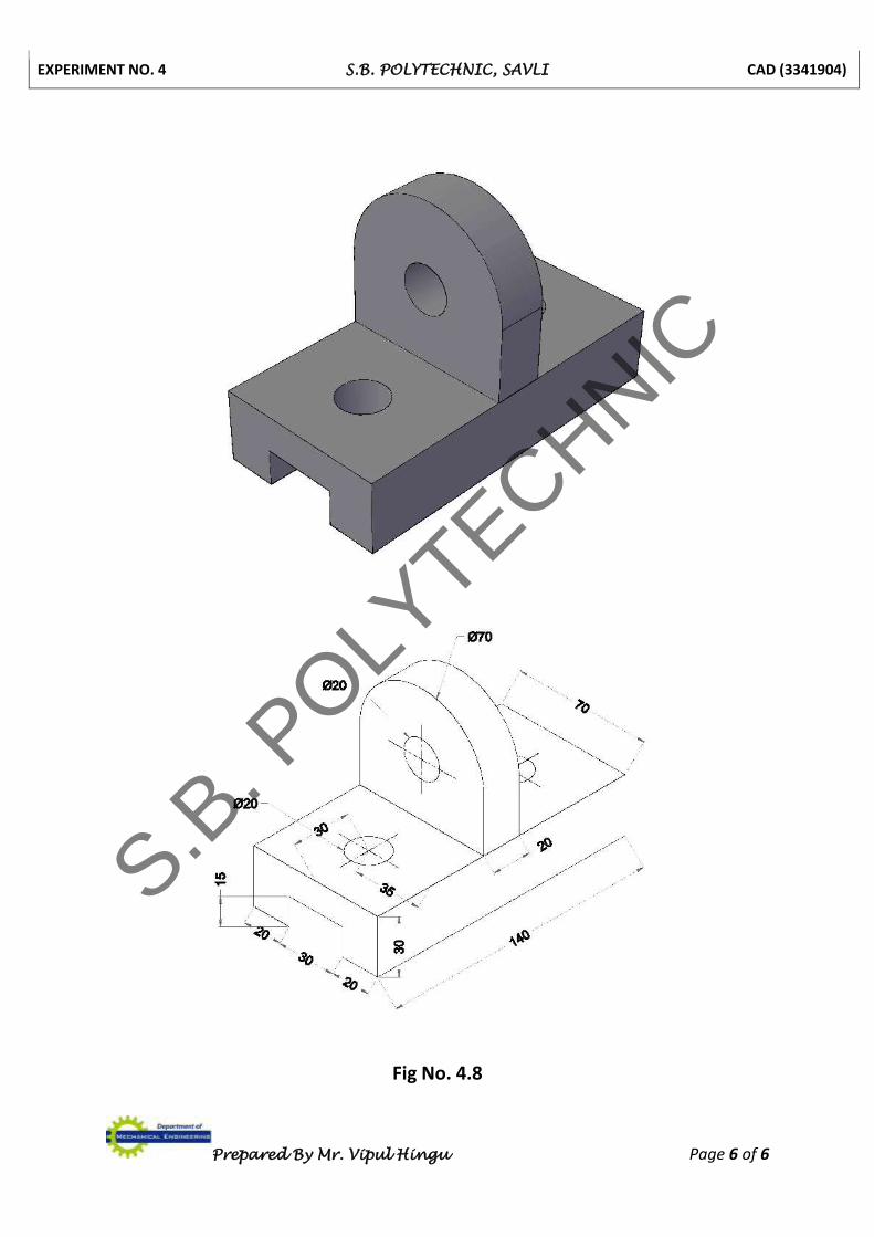
Fig No. 4.8
S.B. P
OLYTECHNIC
EXPERIMENT NO. 5 S.B. POLYTECHNIC, SAVLI CAD (3341904)
Prepared By Mr. Vipul Hingu Page 1 of 6
EXPERIMENT NO. 5
3D SOLID MODELING - II (AUTODESK INVENTOR)
Prepare 3D Model using Autodesk Inventor.
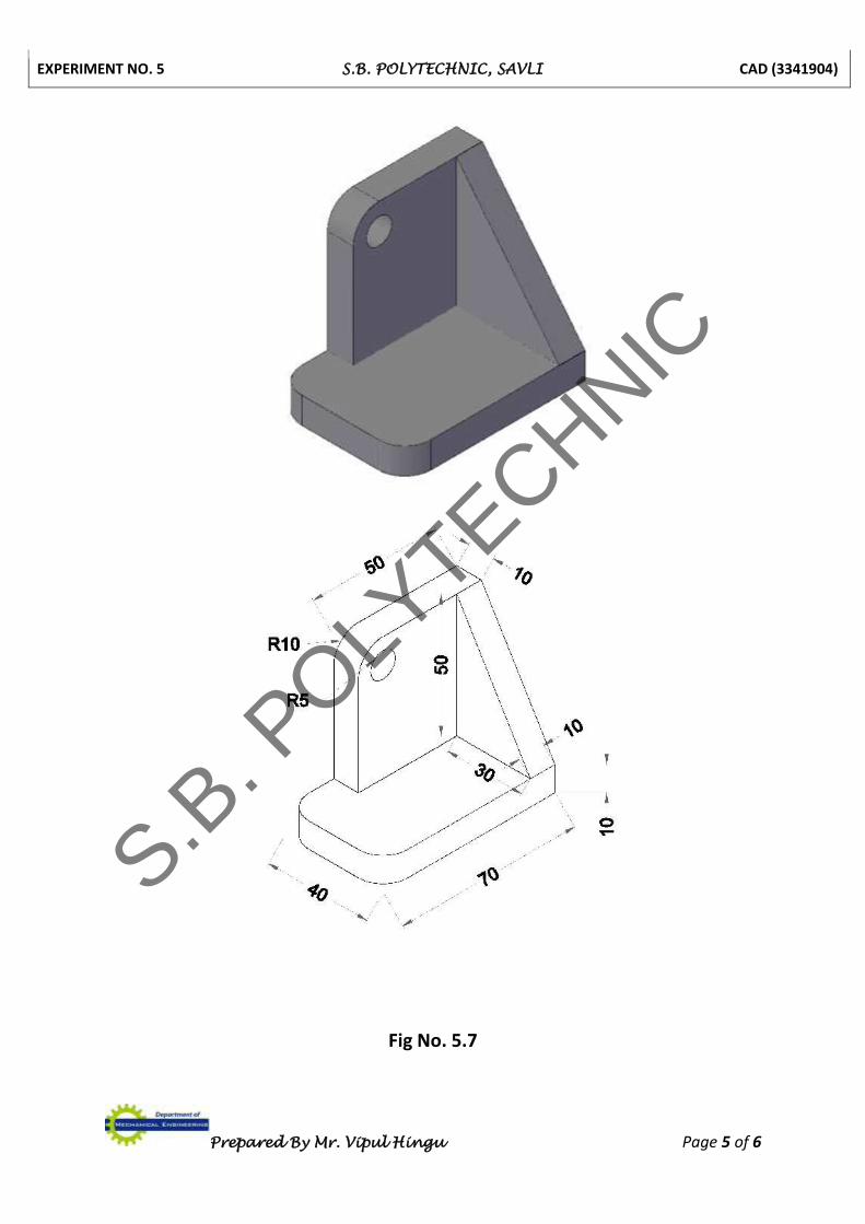
Draw Fig 5.7 in Autodesk Inventor and write down all steps.
STEP – 1
Open the Autodesk Inventor by double clicking the mouse, select part file.
STEP – 2
For creating new part click by mouse on 2D sketch Icon and select by mouse click XZ Plane.
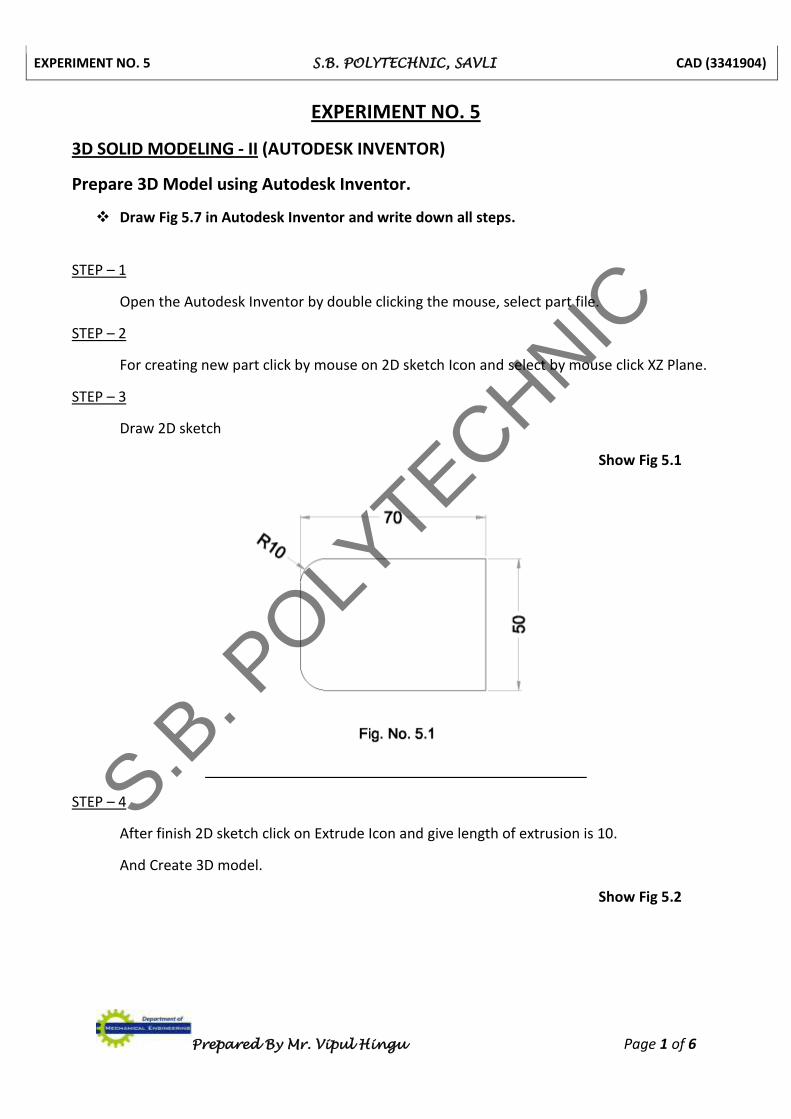
STEP – 3
Draw 2D sketch
Show Fig 5.1
STEP – 4
After finish 2D sketch click on Extrude Icon and give length of extrusion is 10.
And Create 3D model.
Show Fig 5.2
S.B. P
OLYTECHNIC
EXPERIMENT NO. 5 S.B. POLYTECHNIC, SAVLI CAD (3341904)
Prepared By Mr. Vipul Hingu Page 2 of 6
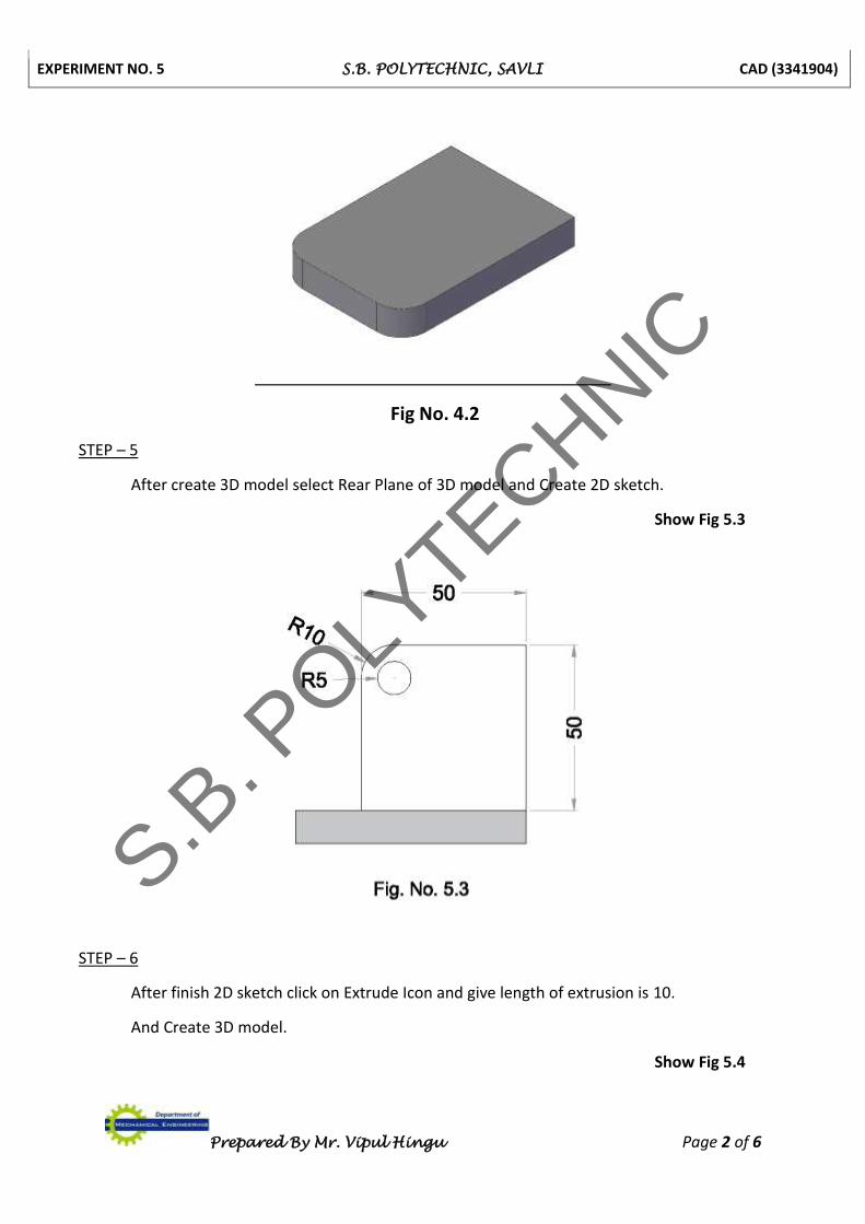
Fig No. 4.2
STEP – 5
After create 3D model select Rear Plane of 3D model and Create 2D sketch.
Show Fig 5.3
STEP – 6
After finish 2D sketch click on Extrude Icon and give length of extrusion is 10.
And Create 3D model.
Show Fig 5.4
S.B. P
OLYTECHNIC

EXPERIMENT NO. 5 S.B. POLYTECHNIC, SAVLI CAD (3341904)
Prepared By Mr. Vipul Hingu Page 3 of 6
Fig No. 5.4
STEP – 7
After create 3D model select Rear Plane of 3D model and Create 2D sketch.
STEP – 8
After finish 2D sketch click on Extrude Icon and give length of Extrude Cut is 10.
Show Fig 5.5
Fig No. 5.5
S.B. P
OLYTECHNIC
EXPERIMENT NO. 5 S.B. POLYTECHNIC, SAVLI CAD (3341904)
Prepared By Mr. Vipul Hingu Page 4 of 6
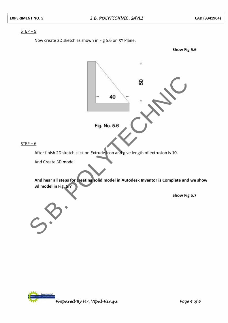
STEP – 9
Now create 2D sketch as shown in Fig 5.6 on XY Plane.
Show Fig 5.6
STEP – 6
After finish 2D sketch click on Extrude Icon and give length of extrusion is 10.
And Create 3D model
And hear all steps for creating solid model in Autodesk Inventor is Complete and we show
3d model in Fig. 5.7
Show Fig 5.7
S.B. P
OLYTECHNIC
EXPERIMENT NO. 5 S.B. POLYTECHNIC, SAVLI CAD (3341904)
Prepared By Mr. Vipul Hingu Page 5 of 6
Fig No. 5.7
S.B. P
OLYTECHNIC
EXPERIMENT NO. 5 S.B. POLYTECHNIC, SAVLI CAD (3341904)
Prepared By Mr. Vipul Hingu Page 6 of 6
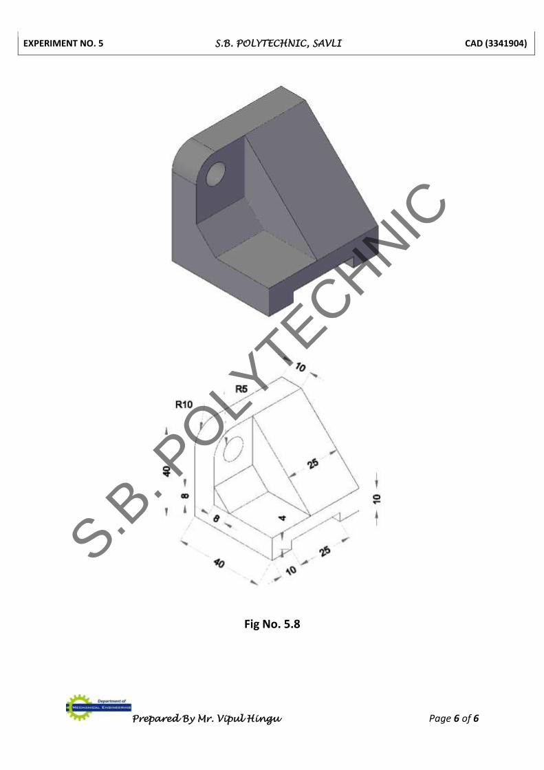
Fig No. 5.8
S.B. P
OLYTECHNIC