
32-Zone Wireless Transceiver Security Systems MG5000 V3.2 ... SP... · PARADOX.COM Programming...
76
PARADOX.COM Programming Guide 32-Zone Wireless Transceiver Security Systems MG5000 V3.2 MG5050 V3.2 5- to 32-Zone Expandable Security Systems SP5500 V3.2 SP6000 V3.2 SP7000 V3.2 Always Armed, Never Disarmed
Transcript of 32-Zone Wireless Transceiver Security Systems MG5000 V3.2 ... SP... · PARADOX.COM Programming...

Programming Guide
32-Zone Wireless Transceiver Security SystemsMG5000 V3.2MG5050 V3.2
5- to 32-Zone Expandable Security SystemsSP5500 V3.2SP6000 V3.2SP7000 V3.2
Always Armed, Never Disarmed
PARADOX.COM


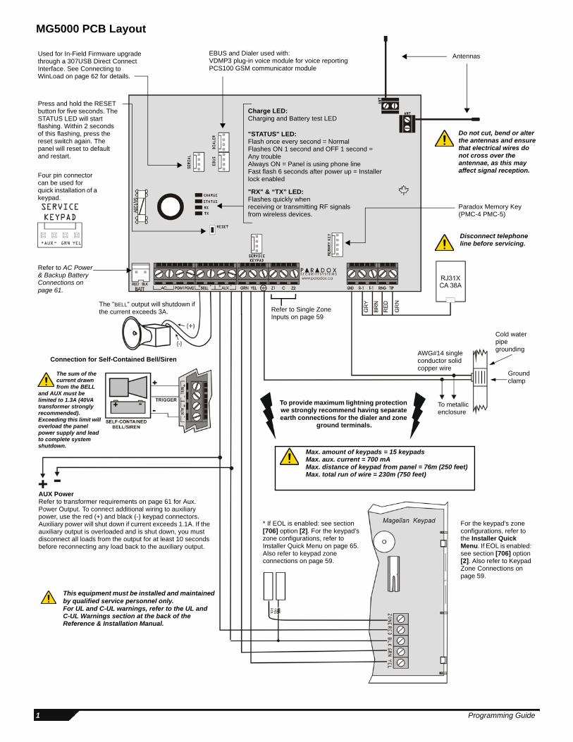
MG5000 PCB Layout
Refer to Single Zone Inputs on page 59
Refer to AC Power & Backup Battery Connections on page 61.
For the keypad’s zone configurations, refer to the Installer Quick Menu. If EOL is enabled: see section [706] option [2]. Also refer to Keypad Zone Connections on page 59.
AUX Power Refer to transformer requirements on page 61 for Aux. Power Output. To connect additional wiring to auxiliary power, use the red (+) and black (-) keypad connectors. Auxiliary power will shut down if current exceeds 1.1A. If the auxiliary output is overloaded and is shut down, you must disconnect all loads from the output for at least 10 seconds before reconnecting any load back to the auxiliary output.
To provide maximum lightning protection we strongly recommend having separate earth connections for the dialer and zone
ground terminals.
To metallic enclosure
Ground clamp
AWG#14 single conductor solid copper wire
Cold water pipe grounding
The "BELL" output will shutdown if the current exceeds 3A.
Disconnect telephone line before servicing.
Four pin connector can be used for quick installation of a keypad.
Do not cut, bend or alter the antennas and ensure that electrical wires do not cross over the antennae, as this may affect signal reception.
Paradox Memory Key (PMC-4 PMC-5)
Antennas
"RX" & “TX” LED:Flashes quickly whenreceiving or transmitting RF signals from wireless devices.
"STATUS" LED:Flash once every second = NormalFlashes ON 1 second and OFF 1 second = Any troubleAlways ON = Panel is using phone lineFast flash 6 seconds after power up = Installer lock enabled
This equipment must be installed and maintained by qualified service personnel only.For UL and C-UL warnings, refer to the UL and C-UL Warnings section at the back of the Reference & Installation Manual.
Used for In-Field Firmware upgrade through a 307USB Direct Connect Interface. See Connecting to WinLoad on page 62 for details.
EBUS and Dialer used with:VDMP3 plug-in voice module for voice reportingPCS100 GSM communicator module
Press and hold the RESET button for five seconds. The STATUS LED will start flashing. Within 2 seconds of this flashing, press the reset switch again. The panel will reset to default and restart.
The sum of the current drawn from the BELL
and AUX must be limited to 1.3A (40VA transformer strongly recommended). Exceeding this limit will overload the panel power supply and lead to complete system shutdown.
Connection for Self-Contained Bell/Siren
Max. amount of keypads = 15 keypadsMax. aux. current = 700 mAMax. distance of keypad from panel = 76m (250 feet)Max. total run of wire = 230m (750 feet)
Charge LED:Charging and Battery test LED
* If EOL is enabled: see section [706] option [2]. For the keypad’s zone configurations, refer to Installer Quick Menu on page 65. Also refer to keypad zone connections on page 59.
1 Programming Guide
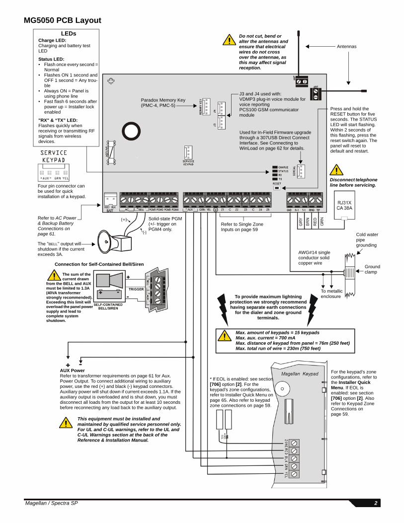
MG5050 PCB Layout
Used for In-Field Firmware upgrade through a 307USB Direct Connect Interface. See Connecting to WinLoad on page 62 for details.
Antennas
Do not cut, bend or alter the antennas and ensure that electrical wires do not cross over the antennae, as this may affect signal reception.
Four pin connector can be used for quick installation of a keypad.
Refer to AC Power & Backup Battery Connections on page 61.
Paradox Memory Key (PMC-4, PMC-5)
LEDsCharge LED:Charging and battery test LED
Status LED: • Flash once every second =
Normal• Flashes ON 1 second and
OFF 1 second = Any trou-ble
• Always ON = Panel is using phone line
• Fast flash 6 seconds after power up = Installer lock enabled
"RX" & “TX” LED:Flashes quickly when receiving or transmitting RF signals from wireless devices.
To metallic enclosure
Ground clamp
AWG#14 single conductor solid copper wire
Cold water pipe grounding
To provide maximum lightning protection we strongly recommend having separate earth connections
for the dialer and zone ground terminals.
The "BELL" output will shutdown if the current exceeds 3A.
Refer to Single Zone Inputs on page 59
Max. amount of keypads = 15 keypadsMax. aux. current = 700 mAMax. distance of keypad from panel = 76m (250 feet)Max. total run of wire = 230m (750 feet)
Disconnect telephone line before servicing.
AUX Power Refer to transformer requirements on page 61 for Aux. Power Output. To connect additional wiring to auxiliary power, use the red (+) and black (-) keypad connectors. Auxiliary power will shut down if current exceeds 1.1A. If the auxiliary output is overloaded and is shut down, you must disconnect all loads from the output for at least 10 seconds before reconnecting any load back to the auxiliary output.
This equipment must be installed and maintained by qualified service personnel only.For UL and C-UL warnings, refer to the UL and C-UL Warnings section at the back of the Reference & Installation Manual.
The sum of the current drawn
from the BELL and AUX must be limited to 1.3A (40VA transformer strongly recommended). Exceeding this limit will overload the panel power supply and lead to complete system shutdown.
Connection for Self-Contained Bell/Siren
For the keypad’s zone configurations, refer to the Installer Quick Menu. If EOL is enabled: see section [706] option [2]. Also refer to Keypad Zone Connections on page 59.
Press and hold the RESET button for five seconds. The STATUS LED will start flashing. Within 2 seconds of this flashing, press the reset switch again. The panel will reset to default and restart.
* If EOL is enabled: see section [706] option [2]. For the keypad’s zone configurations, refer to Installer Quick Menu on page 65. Also refer to keypad zone connections on page 59.
*
Solid-state PGM (+/- trigger on PGM4 only.
J3 and J4 used with:VDMP3 plug-in voice module for voice reportingPCS100 GSM communicator module
Magellan / Spectra SP 2

SP5500 PCB Layout
Four pin connector can be used for quick installation of a SP5500 keypad.
Used for In-Field Firmware upgrade through a 307USB Direct Connect Interface. See Connecting to WinLoad on page 62 for details.
Paradox Memory Key (PMC-4, PMC5)
Refer to AC Power & Backup Battery Connections on page 61.
The "BELL" output will shutdown if the current exceeds 3A.
AUX Power Refer to transformer requirements on page 61 for Aux. Power Output. To connect additional wiring to auxiliary power, use the red (+) and black (-) keypad connectors. Auxiliary power will shut down if current exceeds 1.1A. If the auxiliary output is overloaded and is shut down, you must disconnect all loads from the output for at least 10 seconds before reconnecting any load back to the auxiliary output.
This equipment must be installed and maintained by qualified service personnel only.For UL and C-UL warnings, refer to the UL and C-UL Warnings section at the back of the Reference & Installation Manual.
The sum of the current drawn from the BELL and AUX must be limited to 1.3A (40VA transformer strongly recommended). Exceeding this limit will overload the panel power supply and lead to complete system shutdown.
Connection for Self-Contained Bell/Siren
To provide maximum lightning protection we strongly recommend having separate earth connections
for the dialer and zone ground terminals.
Max. amount of keypads = 15 keypadsMax. aux. current = 700 mAMax. distance of keypad from panel = 76m (250 feet)Max. total run of wire = 230m (750 feet)
Disconnect telephone line before servicing.
To metallic enclosure
Ground clamp
AWG#14 single conductor solid copper wire
Cold water pipe grounding
For the keypad’s zone configurations, refer to the Installer Quick Menu. If EOL is enabled: see section [706] option [2]. Also refer to Keypad Zone Connections on page 59.
Refer to Single Zone Inputs on page 59
PGM +/- trigger not supported by the SP5500
Press and hold the RESET button for five seconds. The STATUS LED will start flashing. Within 2 seconds of this flashing, press the reset switch again. The panel will reset to default and restart.
Charge LED:Charging and battery test LED
Status LED: • Flash once every second = Normal• Flashes ON 1 second and OFF 1 second = Any trouble • Always ON = Panel is using phone line • Fast flash 6 seconds after power up = Installer lock enabled
EBUS and Dialer used with:VDMP3 plug-in voice module for voice reportingPCS100 GSM communicator module
* If EOL is enabled: see section [706] option [2]. For the keypad’s zone configurations, refer to Installer Quick Menu on page 65. Also refer to keypad zone connections on page 59.
3 Programming Guide

SP6000 PCB LayoutLEDs
Charge LED:Charging and battery test LED
Status LED: • Flash once every second = Normal• Flashes ON 1 second and OFF 1 second = Any trouble • Always ON = Panel is using phone line • Fast flash 6 seconds after power up = Installer lock enabled
Four pin connector can be used for quick installation of a keypad.
Used for In-Field Firmware upgrade through a 307USB Direct Connect Interface. See Connecting to WinLoad on page 62 for details.
Paradox Memory Key (PMC-4, PMC-5)
Refer to AC Power & Backup Battery Connections on page 61.
The "BELL" output will shutdown if the current exceeds 3A.
AUX Power Refer to transformer requirements on page 61 for Aux. Power Output. To connect additional wiring to auxiliary power, use the red (+) and black (-) keypad connectors. Auxiliary power will shut down if current exceeds 1.1A. If the auxiliary output is overloaded and is shut down, you must disconnect all loads from the output for at least 10 seconds before reconnecting any load back to the auxiliary output.
This equipment must be installed and maintained by qualified service personnel only.For UL and C-UL warnings, refer to the UL and C-UL Warnings section at the back of the Reference & Installation Manual.
The sum of the current drawn from the BELL and AUX must be limited to 1.3A (40VA transformer strongly recommended). Exceeding this limit will overload the panel power supply and lead to complete system shutdown.
Connection for Self-Contained Bell/Siren
To provide maximum lightning protection we strongly recommend having separate earth connections
for the dialer and zone ground terminals.
Max. amount of keypads = 15 keypadsMax. aux. current = 700 mAMax. distance of keypad from panel = 76m (250 feet)Max. total run of wire = 230m (750 feet)
Disconnect telephone line before servicing.
To metallic enclosure
Ground clamp
AWG#14 single conductor solid copper wire
Cold water pipe grounding
For the keypad’s zone configurations, refer to the Installer Quick Menu. If EOL is enabled: see section [706] option [2]. Also refer to Keypad Zone Connections on page 59.
Refer to Single Zone Inputs on page 59
PGM Trigger: This jumper allows you to choose whether the solid state relay PGMs are grounded (-), or give out 12V (+).
Press and hold the RESET button for five seconds. The STATUS LED will start flashing. Within 2 seconds of this flashing, press the reset switch again. The panel will reset to default and restart.
When using an SP6000 panel in conjunction with an RTX3, all K32 and K10V/H keypads must be versions 2.0 or higher.
* If EOL is enabled: see section [706] option [2]. For the keypad’s zone configurations, refer to Installer Quick Menu on page 65. Also refer to keypad zone connections on page 59.
*
EBUS and Dialer used with:VDMP3 plug-in voice module for voice reportingPCS100 GSM communicator module
Magellan / Spectra SP 4

SP7000 PCB LayoutLEDs
Charge LED:Charging and battery test LED
Status LED: • Flash once every second = Normal• Flashes ON 1 second and OFF 1 second = Any trouble • Always ON = Panel is using phone line • Fast flash 6 seconds after power up = Installer lock enabled
Four pin connector can be used for quick installation of a keypad.
Used for In-Field Firmware upgrade through a 307USB Direct Connect Interface. See Connecting to WinLoad on page 62 for details.
Paradox Memory Key (PMC-4, PMC-5)
Refer to AC Power & Backup Battery Connections on page 61.
The "BELL" output will shutdown if the current exceeds 3A.
AUX Power Refer to transformer requirements on page 61 for Aux. Power Output. To connect additional wiring to auxiliary power, use the red (+) and black (-) keypad connectors. Auxiliary power will shut down if current exceeds 1.1A. If the auxiliary output is overloaded and is shut down, you must disconnect all loads from the output for at least 10 seconds before reconnecting any load back to the auxiliary output.
This equipment must be installed and maintained by qualified service personnel only.For UL and C-UL warnings, refer to the UL and C-UL Warnings section at the back of the Reference & Installation Manual.
The sum of the current drawn from the BELL and AUX must be limited to 1.3A (40VA transformer strongly recommended). Exceeding this limit will overload the panel power supply and lead to complete system shutdown.
Connection for Self-Contained Bell/Siren
To provide maximum lightning protection we strongly recommend having separate earth connections
for the dialer and zone ground terminals.
Max. amount of keypads = 15 keypadsMax. aux. current = 700 mAMax. distance of keypad from panel = 76m (250 feet)Max. total run of wire = 230m (750 feet)
Disconnect telephone line before servicing.
To metallic enclosure
Ground clamp
AWG#14 single conductor solid copper wire
Cold water pipe grounding
For the keypad’s zone configurations, refer to the Installer Quick Menu. If EOL is enabled: see section [706] option [2]. Also refer to Keypad Zone Connections on page 59.
Refer to Single Zone Inputs on page 59
PGM Trigger: This jumper allows you to choose whether the solid state relay PGMs are grounded (-), or give out 12V (+). Upper Inputs = Zones 9 to 16
Lower Inputs = Zones 1 to 8
Press and hold the RESET button for five seconds. The STATUS LED will start flashing. Within 2 seconds of this flashing, press the reset switch again. The panel will reset to default and restart.
* If EOL is enabled: see section [706] option [2]. For the keypad’s zone configurations, refer to Installer Quick Menu on page 65. Also refer to keypad zone connections on page 59.
*
Z1 Z2 Z3 Z4 C Z5 Z6 Z7 Z8 C
Z9 Z10 Z11 Z12 C Z13 Z14 Z15 Z16 C
EBUS and Dialer used with:VDMP3 plug-in voice module for voice reportingPCS100 GSM communicator module
May be labeled ADM2 on some panels
5 Programming Guide
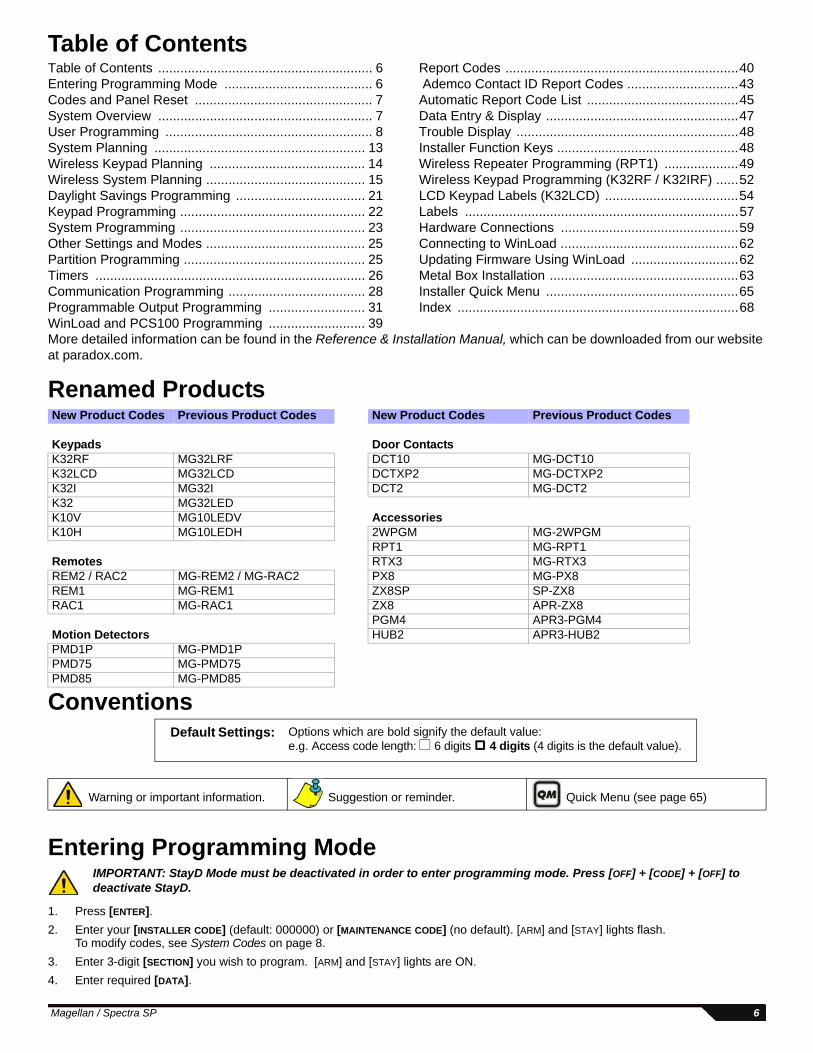
Table of Contents
More detailed information can be found in the Reference & Installation Manual, which can be downloaded from our website at paradox.com.
Renamed Products
Conventions
Entering Programming ModeIMPORTANT: StayD Mode must be deactivated in order to enter programming mode. Press [OFF] + [CODE] + [OFF] to deactivate StayD.
1. Press [ENTER].2. Enter your [INSTALLER CODE] (default: 000000) or [MAINTENANCE CODE] (no default). [ARM] and [STAY] lights flash.
To modify codes, see System Codes on page 8.3. Enter 3-digit [SECTION] you wish to program. [ARM] and [STAY] lights are ON.4. Enter required [DATA].
New Product Codes Previous Product Codes New Product Codes Previous Product Codes
Keypads Door ContactsK32RF MG32LRF DCT10 MG-DCT10K32LCD MG32LCD DCTXP2 MG-DCTXP2K32I MG32I DCT2 MG-DCT2K32 MG32LEDK10V MG10LEDV AccessoriesK10H MG10LEDH 2WPGM MG-2WPGM
RPT1 MG-RPT1Remotes RTX3 MG-RTX3REM2 / RAC2 MG-REM2 / MG-RAC2 PX8 MG-PX8REM1 MG-REM1 ZX8SP SP-ZX8RAC1 MG-RAC1 ZX8 APR-ZX8
PGM4 APR3-PGM4Motion Detectors HUB2 APR3-HUB2PMD1P MG-PMD1PPMD75 MG-PMD75PMD85 MG-PMD85
Warning or important information. Suggestion or reminder. Quick Menu (see page 65)
Table of Contents .......................................................... 6Entering Programming Mode ........................................ 6Codes and Panel Reset ................................................ 7System Overview .......................................................... 7User Programming ........................................................ 8System Planning ......................................................... 13Wireless Keypad Planning .......................................... 14Wireless System Planning ........................................... 15Daylight Savings Programming ................................... 21Keypad Programming .................................................. 22System Programming .................................................. 23Other Settings and Modes ........................................... 25Partition Programming ................................................. 25Timers ......................................................................... 26Communication Programming ..................................... 28Programmable Output Programming .......................... 31WinLoad and PCS100 Programming .......................... 39
Report Codes ...............................................................40 Ademco Contact ID Report Codes ..............................43Automatic Report Code List .........................................45Data Entry & Display ....................................................47Trouble Display ............................................................48Installer Function Keys .................................................48Wireless Repeater Programming (RPT1) ....................49Wireless Keypad Programming (K32RF / K32IRF) ......52LCD Keypad Labels (K32LCD) ....................................54Labels ..........................................................................57Hardware Connections ................................................59Connecting to WinLoad ................................................62Updating Firmware Using WinLoad .............................62Metal Box Installation ...................................................63Installer Quick Menu ....................................................65Index ............................................................................68
Default Settings: Options which are bold signify the default value: e.g. Access code length: 6 digits 4 digits (4 digits is the default value).
Magellan / Spectra SP 6
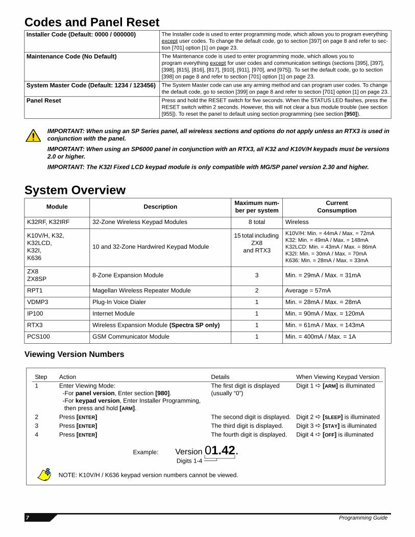
Codes and Panel Reset
IMPORTANT: When using an SP Series panel, all wireless sections and options do not apply unless an RTX3 is used in conjunction with the panel.
IMPORTANT: When using an SP6000 panel in conjunction with an RTX3, all K32 and K10V/H keypads must be versions 2.0 or higher. IMPORTANT: The K32I Fixed LCD keypad module is only compatible with MG/SP panel version 2.30 and higher.
System Overview
Viewing Version Numbers
Installer Code (Default: 0000 / 000000) The Installer code is used to enter programming mode, which allows you to program everything except user codes. To change the default code, go to section [397] on page 8 and refer to sec-tion [701] option [1] on page 23.
Maintenance Code (No Default) The Maintenance code is used to enter programming mode, which allows you to program everything except for user codes and communication settings (sections [395], [397], [398], [815], [816], [817], [910], [911], [970], and [975]). To set the default code, go to section [398] on page 8 and refer to section [701] option [1] on page 23.
System Master Code (Default: 1234 / 123456) The System Master code can use any arming method and can program user codes. To change the default code, go to section [399] on page 8 and refer to section [701] option [1] on page 23.
Panel Reset Press and hold the RESET switch for five seconds. When the STATUS LED flashes, press the RESET switch within 2 seconds. However, this will not clear a bus module trouble (see section [955]). To reset the panel to default using section programming (see section [950]).
Module Description Maximum num-ber per system
Current Consumption
K32RF, K32IRF 32-Zone Wireless Keypad Modules 8 total Wireless
K10V/H, K32, K32LCD,K32I,K636
10 and 32-Zone Hardwired Keypad Module
15 total including ZX8
and RTX3
K10V/H: Min. = 44mA / Max. = 72mAK32: Min. = 49mA / Max. = 148mAK32LCD: Min. = 43mA / Max. = 86mAK32I: Min. = 30mA / Max. = 70mAK636: Min. = 28mA / Max. = 33mA
ZX8ZX8SP 8-Zone Expansion Module 3 Min. = 29mA / Max. = 31mA
RPT1 Magellan Wireless Repeater Module 2 Average = 57mA
VDMP3 Plug-In Voice Dialer 1 Min. = 28mA / Max. = 28mA
IP100 Internet Module 1 Min. = 90mA / Max. = 120mA
RTX3 Wireless Expansion Module (Spectra SP only) 1 Min. = 61mA / Max. = 143mA
PCS100 GSM Communicator Module 1 Min. = 400mA / Max. = 1A
Example: Version 01.42.Digits 1-4
Step Action Details When Viewing Keypad Version1 Enter Viewing Mode:
-For panel version, Enter section [980]. -For keypad version, Enter Installer Programming, then press and hold [ARM].
The first digit is displayed(usually “0”)
Digit 1 [ARM] is illuminated
2 Press [ENTER] The second digit is displayed. Digit 2 [SLEEP] is illuminated3 Press [ENTER] The third digit is displayed. Digit 3 [STAY] is illuminated4 Press [ENTER] The fourth digit is displayed. Digit 4 [OFF] is illuminated
NOTE: K10V/H / K636 keypad version numbers cannot be viewed.
7 Programming Guide
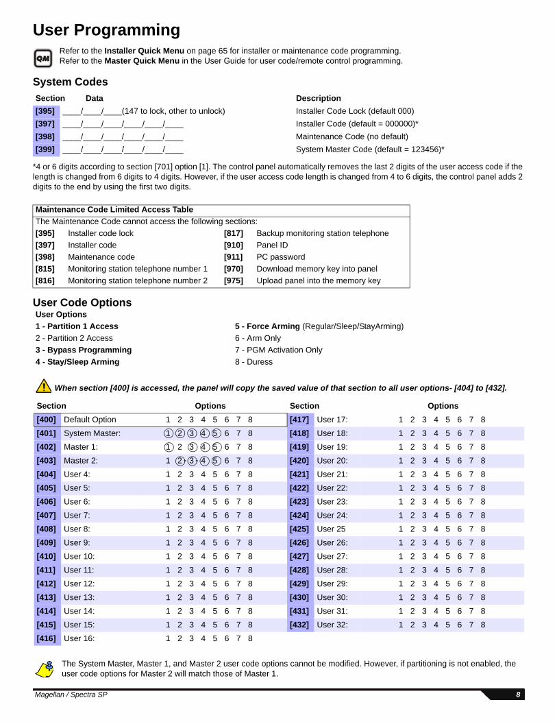
User ProgrammingRefer to the Installer Quick Menu on page 65 for installer or maintenance code programming.Refer to the Master Quick Menu in the User Guide for user code/remote control programming.
System Codes
*4 or 6 digits according to section [701] option [1]. The control panel automatically removes the last 2 digits of the user access code if the length is changed from 6 digits to 4 digits. However, if the user access code length is changed from 4 to 6 digits, the control panel adds 2 digits to the end by using the first two digits.
User Code Options
When section [400] is accessed, the panel will copy the saved value of that section to all user options- [404] to [432].
The System Master, Master 1, and Master 2 user code options cannot be modified. However, if partitioning is not enabled, the user code options for Master 2 will match those of Master 1.
Section Data Description[395] ____/____/____(147 to lock, other to unlock) Installer Code Lock (default 000)[397] ____/____/____/____/____/____ Installer Code (default = 000000)*[398] ____/____/____/____/____/____ Maintenance Code (no default)[399] ____/____/____/____/____/____ System Master Code (default = 123456)*
Maintenance Code Limited Access TableThe Maintenance Code cannot access the following sections:[395] Installer code lock [817] Backup monitoring station telephone[397] Installer code [910] Panel ID[398] Maintenance code [911] PC password[815] Monitoring station telephone number 1 [970] Download memory key into panel [816] Monitoring station telephone number 2 [975] Upload panel into the memory key
User Options1 - Partition 1 Access 5 - Force Arming (Regular/Sleep/StayArming)2 - Partition 2 Access 6 - Arm Only3 - Bypass Programming 7 - PGM Activation Only4 - Stay/Sleep Arming 8 - Duress
Section Options Section Options[400] Default Option 1 2 3 4 5 6 7 8 [417] User 17: 1 2 3 4 5 6 7 8
[401] System Master: 1 2 3 4 5 6 7 8 [418] User 18: 1 2 3 4 5 6 7 8
[402] Master 1: 1 2 3 4 5 6 7 8 [419] User 19: 1 2 3 4 5 6 7 8
[403] Master 2: 1 2 3 4 5 6 7 8 [420] User 20: 1 2 3 4 5 6 7 8
[404] User 4: 1 2 3 4 5 6 7 8 [421] User 21: 1 2 3 4 5 6 7 8
[405] User 5: 1 2 3 4 5 6 7 8 [422] User 22: 1 2 3 4 5 6 7 8
[406] User 6: 1 2 3 4 5 6 7 8 [423] User 23: 1 2 3 4 5 6 7 8
[407] User 7: 1 2 3 4 5 6 7 8 [424] User 24: 1 2 3 4 5 6 7 8
[408] User 8: 1 2 3 4 5 6 7 8 [425] User 25 1 2 3 4 5 6 7 8
[409] User 9: 1 2 3 4 5 6 7 8 [426] User 26: 1 2 3 4 5 6 7 8
[410] User 10: 1 2 3 4 5 6 7 8 [427] User 27: 1 2 3 4 5 6 7 8
[411] User 11: 1 2 3 4 5 6 7 8 [428] User 28: 1 2 3 4 5 6 7 8
[412] User 12: 1 2 3 4 5 6 7 8 [429] User 29: 1 2 3 4 5 6 7 8
[413] User 13: 1 2 3 4 5 6 7 8 [430] User 30: 1 2 3 4 5 6 7 8
[414] User 14: 1 2 3 4 5 6 7 8 [431] User 31: 1 2 3 4 5 6 7 8
[415] User 15: 1 2 3 4 5 6 7 8 [432] User 32: 1 2 3 4 5 6 7 8
[416] User 16: 1 2 3 4 5 6 7 8
Magellan / Spectra SP 8

Remote Control Button Assignment
REM1 REM2RAC1 RAC2
* Buttons are programmed using the Button Options Table below.
Default data*: 1 B C disabled
REM3 PGM1[9]
PGM2[0]
PGM3[x]
PGM4[ ]
PGM5 [ ]
PGM6[ ]
PGM3&4[x] + [ ]
PGM5&6[ ] + [ ]
Default data*: B C D E 5 6 disabled disabled
[610] All RCs ______ ______ ______ ______ ______ ______ ______ ______RC# IMPORTANT: When section [610] is accessed, the panel will copy the saved value of that section to all remotes.
[611] 1 ______ ______ ______ ______ ______ ______ ______ ______[612] 2 ______ ______ ______ ______ ______ ______ ______ ______[613] 3 ______ ______ ______ ______ ______ ______ ______ ______[614] 4 ______ ______ ______ ______ ______ ______ ______ ______[615] 5 ______ ______ ______ ______ ______ ______ ______ ______[616] 6 ______ ______ ______ ______ ______ ______ ______ ______[617] 7 ______ ______ ______ ______ ______ ______ ______ ______[618] 8 ______ ______ ______ ______ ______ ______ ______ ______[619] 9 ______ ______ ______ ______ ______ ______ ______ ______[620] 10 ______ ______ ______ ______ ______ ______ ______ ______[621] 11 ______ ______ ______ ______ ______ ______ ______ ______[622] 12 ______ ______ ______ ______ ______ ______ ______ ______[623] 13 ______ ______ ______ ______ ______ ______ ______ ______[624] 14 ______ ______ ______ ______ ______ ______ ______ ______[625] 15 ______ ______ ______ ______ ______ ______ ______ ______[626] 16 ______ ______ ______ ______ ______ ______ ______ ______[627] 17 ______ ______ ______ ______ ______ ______ ______ ______[628] 18 ______ ______ ______ ______ ______ ______ ______ ______[629] 19 ______ ______ ______ ______ ______ ______ ______ ______[630] 20 ______ ______ ______ ______ ______ ______ ______ ______[631] 21 ______ ______ ______ ______ ______ ______ ______ ______[632] 22 ______ ______ ______ ______ ______ ______ ______ ______[633] 23 ______ ______ ______ ______ ______ ______ ______ ______[634] 24 ______ ______ ______ ______ ______ ______ ______ ______[635] 25 ______ ______ ______ ______ ______ ______ ______ ______[636] 26 ______ ______ ______ ______ ______ ______ ______ ______[637] 27 ______ ______ ______ ______ ______ ______ ______ ______[638] 28 ______ ______ ______ ______ ______ ______ ______ ______[639] 29 ______ ______ ______ ______ ______ ______ ______ ______[640] 30 ______ ______ ______ ______ ______ ______ ______ ______[641] 31 ______ ______ ______ ______ ______ ______ ______ ______[642] 32 ______ ______ ______ ______ ______ ______ ______ ______
+
+
[SLEEP] - Empty / Button disabled[1] - Regular / Regular Force arming[2] - Stay / Stay Force arming[3] - N/A[4] - Sleep / Sleep Force arming[5] - PGM Activation (Event Group 22)*[6] - PGM Activation (Event Group 23)*[7] - Activate window mode (StayD)[8] - Panic 1[9] - Panic 2
[A] - Panic 3[B] - PGM Activation (Event Group #8)*[C] - PGM Activation (Event Group #9)*[D] - PGM Activation (Event Group #10)* [E] - PGM Activation (Event Group #11)*[F] - Paramedic alarm
* See PGM Programming on page 31.
Button Options Table (refer to Decimal and Hexadecimal Values on page 47) The disarm button ( ) cannot be modified.
Remote Controls Supported:REM1 / REM2 / RAC1 RAC2 / REM3
9 Programming Guide
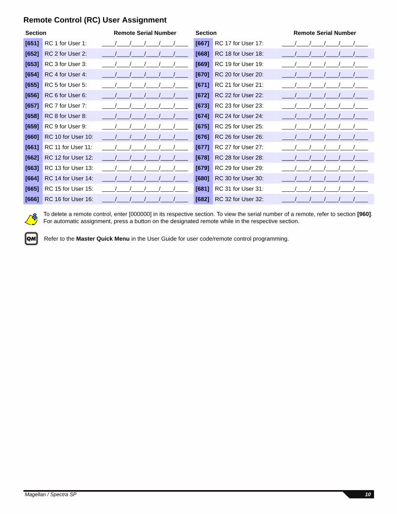
Remote Control (RC) User Assignment
To delete a remote control, enter [000000] in its respective section. To view the serial number of a remote, refer to section [960]. For automatic assignment, press a button on the designated remote while in the respective section.
Refer to the Master Quick Menu in the User Guide for user code/remote control programming.
Section Remote Serial Number Section Remote Serial Number
[651] RC 1 for User 1: ____/____/____/____/____/____ [667] RC 17 for User 17: ____/____/____/____/____/____
[652] RC 2 for User 2: ____/____/____/____/____/____ [668] RC 18 for User 18: ____/____/____/____/____/____
[653] RC 3 for User 3: ____/____/____/____/____/____ [669] RC 19 for User 19: ____/____/____/____/____/____
[654] RC 4 for User 4: ____/____/____/____/____/____ [670] RC 20 for User 20: ____/____/____/____/____/____
[655] RC 5 for User 5: ____/____/____/____/____/____ [671] RC 21 for User 21: ____/____/____/____/____/____
[656] RC 6 for User 6: ____/____/____/____/____/____ [672] RC 22 for User 22: ____/____/____/____/____/____
[657] RC 7 for User 7: ____/____/____/____/____/____ [673] RC 23 for User 23: ____/____/____/____/____/____
[658] RC 8 for User 8: ____/____/____/____/____/____ [674] RC 24 for User 24: ____/____/____/____/____/____
[659] RC 9 for User 9: ____/____/____/____/____/____ [675] RC 25 for User 25: ____/____/____/____/____/____
[660] RC 10 for User 10: ____/____/____/____/____/____ [676] RC 26 for User 26: ____/____/____/____/____/____
[661] RC 11 for User 11: ____/____/____/____/____/____ [677] RC 27 for User 27: ____/____/____/____/____/____
[662] RC 12 for User 12: ____/____/____/____/____/____ [678] RC 28 for User 28: ____/____/____/____/____/____
[663] RC 13 for User 13: ____/____/____/____/____/____ [679] RC 29 for User 29: ____/____/____/____/____/____
[664] RC 14 for User 14: ____/____/____/____/____/____ [680] RC 30 for User 30: ____/____/____/____/____/____
[665] RC 15 for User 15: ____/____/____/____/____/____ [681] RC 31 for User 31: ____/____/____/____/____/____
[666] RC 16 for User 16: ____/____/____/____/____/____ [682] RC 32 for User 32: ____/____/____/____/____/____
Magellan / Spectra SP 10

Code Entry for Action Keys (REM3)The six action keys (PGM1 to PGM6) can be programmed to require a code entry for use.
Section OFF ON[360] [1] All odd-numbered REM3s = Code entry for PGM = One-touch PGM
[2] All odd-numbered REM3s = Code entry disarm = One-touch disarm[3] & [4] N/A N/A
[5] All even-numbered REM3s = Code entry for PGM = One-touch PGM
[6] All even-numbered REM3s = Code entry disarm = One-touch disarm[361] [1] REM3 #1 = Code entry for PGM = One-touch PGM
[2] REM3 #1 = Code entry disarm = One-touch disarm[3] & [4] N/A N/A
[5] REM3 #2 = Code entry for PGM = One-touch PGM
[6] REM3 #2 = Code entry disarm = One-touch disarm[362] [1] REM3 #3 = Code entry for PGM = One-touch PGM
[2] REM3 #3 = Code entry disarm = One-touch disarm[3] & [4] N/A N/A
[5] REM3 #4 = Code entry for PGM = One-touch PGM
[6] REM3 #4 = Code entry disarm = One-touch disarm[363] [1] REM3 #5 = Code entry for PGM = One-touch PGM
[2] REM3 #5 = Code entry disarm = One-touch disarm[3] & [4] N/A N/A
[5] REM3 #6 = Code entry for PGM = One-touch PGM
[6] REM3 #6 = Code entry disarm = One-touch disarm[364] [1] REM3 #7 = Code entry = One-touch PGM
[2] REM3 #7 = Code entry disarm = One-touch disarm[3] & [4] N/A N/A
[5] REM3 #8 = Code entry for PGM = One-touch PGM
[6] REM3 #8 = Code entry disarm = One-touch disarm[365] [1] REM3 #9 = Code entry for PGM = One-touch PGM
[2] REM3 #9 = Code entry disarm = One-touch disarm[3] & [4] N/A N/A
[5] REM3 #10 = Code entry for PGM = One-touch PGM
[6] REM3 #10 = Code entry disarm = One-touch disarm[366] [1] REM3 #11 = Code entry for PGM = One-touch PGM
[2] REM3 #11 = Code entry disarm = One-touch disarm[3] & [4] N/A N/A
[5] REM3 #12 = Code entry for PGM = One-touch PGM
[6] REM3 #12 = Code entry disarm = One-touch disarm[367] [1] REM3 #13 = Code entry for PGM = One-touch PGM
[2] REM3 #13 = Code entry disarm = One-touch disarm[3] & [4] N/A N/A
[5] REM3 #14 = Code entry for PGM = One-touch PGM
[6] REM3 #14 = Code entry disarm = One-touch disarm[368] [1] REM3 #15 = Code entry for PGM = One-touch PGM
[2] REM3 #15 = Code entry disarm = One-touch disarm[3] & [4] N/A N/A
[5] REM3 #16 = Code entry for PGM = One-touch PGM
[6] REM3 #16 = Code entry disarm = One-touch disarm
11 Programming Guide
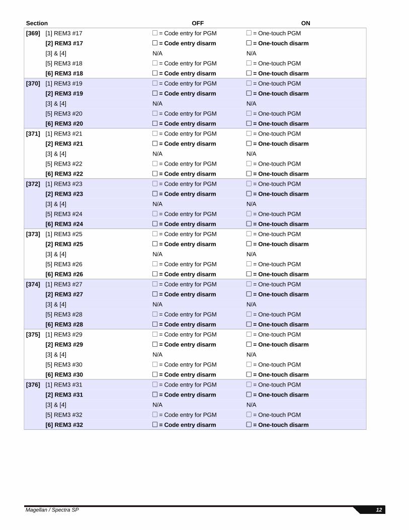
[369] [1] REM3 #17 = Code entry for PGM = One-touch PGM
[2] REM3 #17 = Code entry disarm = One-touch disarm[3] & [4] N/A N/A
[5] REM3 #18 = Code entry for PGM = One-touch PGM
[6] REM3 #18 = Code entry disarm = One-touch disarm[370] [1] REM3 #19 = Code entry for PGM = One-touch PGM
[2] REM3 #19 = Code entry disarm = One-touch disarm[3] & [4] N/A N/A
[5] REM3 #20 = Code entry for PGM = One-touch PGM
[6] REM3 #20 = Code entry disarm = One-touch disarm[371] [1] REM3 #21 = Code entry for PGM = One-touch PGM
[2] REM3 #21 = Code entry disarm = One-touch disarm[3] & [4] N/A N/A
[5] REM3 #22 = Code entry for PGM = One-touch PGM
[6] REM3 #22 = Code entry disarm = One-touch disarm[372] [1] REM3 #23 = Code entry for PGM = One-touch PGM
[2] REM3 #23 = Code entry disarm = One-touch disarm[3] & [4] N/A N/A
[5] REM3 #24 = Code entry for PGM = One-touch PGM
[6] REM3 #24 = Code entry disarm = One-touch disarm[373] [1] REM3 #25 = Code entry for PGM = One-touch PGM
[2] REM3 #25 = Code entry disarm = One-touch disarm[3] & [4] N/A N/A
[5] REM3 #26 = Code entry for PGM = One-touch PGM
[6] REM3 #26 = Code entry disarm = One-touch disarm[374] [1] REM3 #27 = Code entry for PGM = One-touch PGM
[2] REM3 #27 = Code entry disarm = One-touch disarm[3] & [4] N/A N/A
[5] REM3 #28 = Code entry for PGM = One-touch PGM
[6] REM3 #28 = Code entry disarm = One-touch disarm[375] [1] REM3 #29 = Code entry for PGM = One-touch PGM
[2] REM3 #29 = Code entry disarm = One-touch disarm[3] & [4] N/A N/A
[5] REM3 #30 = Code entry for PGM = One-touch PGM
[6] REM3 #30 = Code entry disarm = One-touch disarm[376] [1] REM3 #31 = Code entry for PGM = One-touch PGM
[2] REM3 #31 = Code entry disarm = One-touch disarm[3] & [4] N/A N/A
[5] REM3 #32 = Code entry for PGM = One-touch PGM
[6] REM3 #32 = Code entry disarm = One-touch disarm
Section OFF ON
Magellan / Spectra SP 12
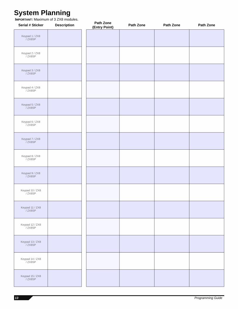
System Planning IMPORTANT: Maximum of 3 ZX8 modules.
Serial # Sticker Description Path Zone (Entry Point) Path Zone Path Zone Path Zone
Keypad 1 / ZX8 / ZX8SP
Keypad 2 / ZX8 / ZX8SP
Keypad 3 / ZX8 / ZX8SP
Keypad 4 / ZX8 / ZX8SP
Keypad 5 / ZX8 / ZX8SP
Keypad 6 / ZX8 / ZX8SP
Keypad 7 / ZX8 / ZX8SP
Keypad 8 / ZX8 / ZX8SP
Keypad 9 / ZX8 / ZX8SP
Keypad 10 / ZX8 / ZX8SP
Keypad 11 / ZX8 / ZX8SP
Keypad 12 / ZX8 / ZX8SP
Keypad 13 / ZX8 / ZX8SP
Keypad 14 / ZX8 / ZX8SP
Keypad 15 / ZX8 / ZX8SP
13 Programming Guide
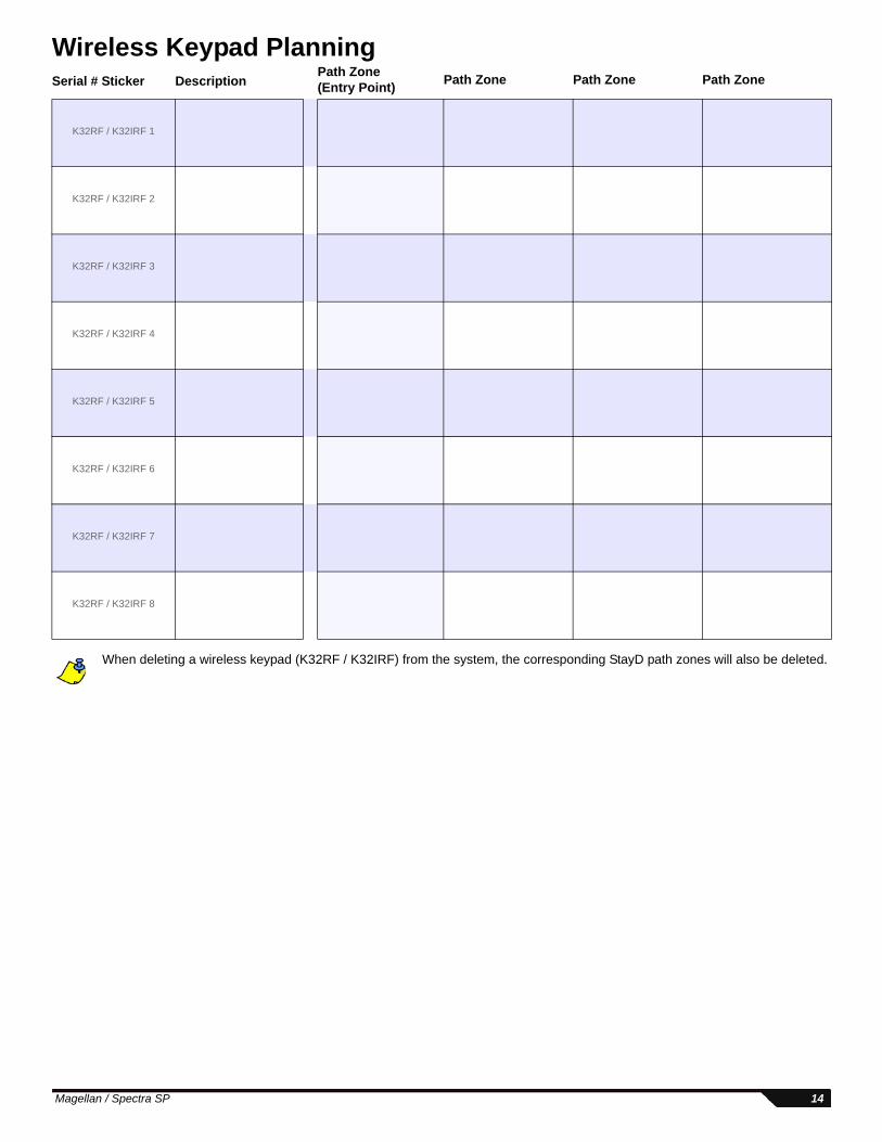
Wireless Keypad Planning
When deleting a wireless keypad (K32RF / K32IRF) from the system, the corresponding StayD path zones will also be deleted.
Serial # Sticker DescriptionPath Zone (Entry Point) Path Zone Path Zone Path Zone
K32RF / K32IRF 1
K32RF / K32IRF 2
K32RF / K32IRF 3
K32RF / K32IRF 4
K32RF / K32IRF 5
K32RF / K32IRF 6
K32RF / K32IRF 7
K32RF / K32IRF 8
Magellan / Spectra SP 14
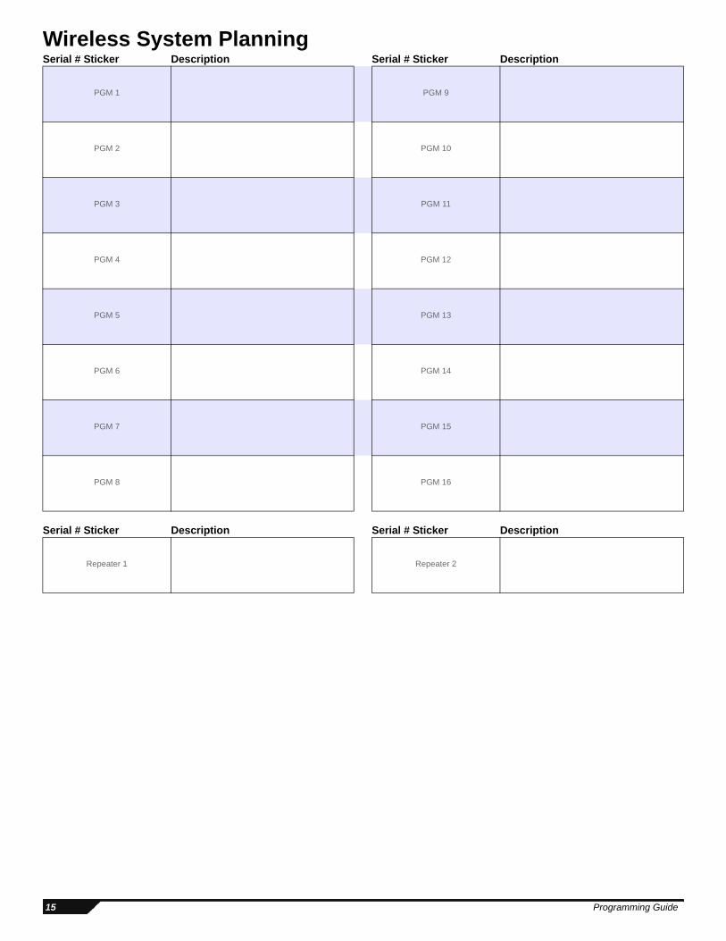
Wireless System PlanningSerial # Sticker Description Serial # Sticker Description
PGM 1 PGM 9
PGM 2 PGM 10
PGM 3 PGM 11
PGM 4 PGM 12
PGM 5 PGM 13
PGM 6 PGM 14
PGM 7 PGM 15
PGM 8 PGM 16
Serial # Sticker Description Serial # Sticker Description
Repeater 1 Repeater 2
15 Programming Guide
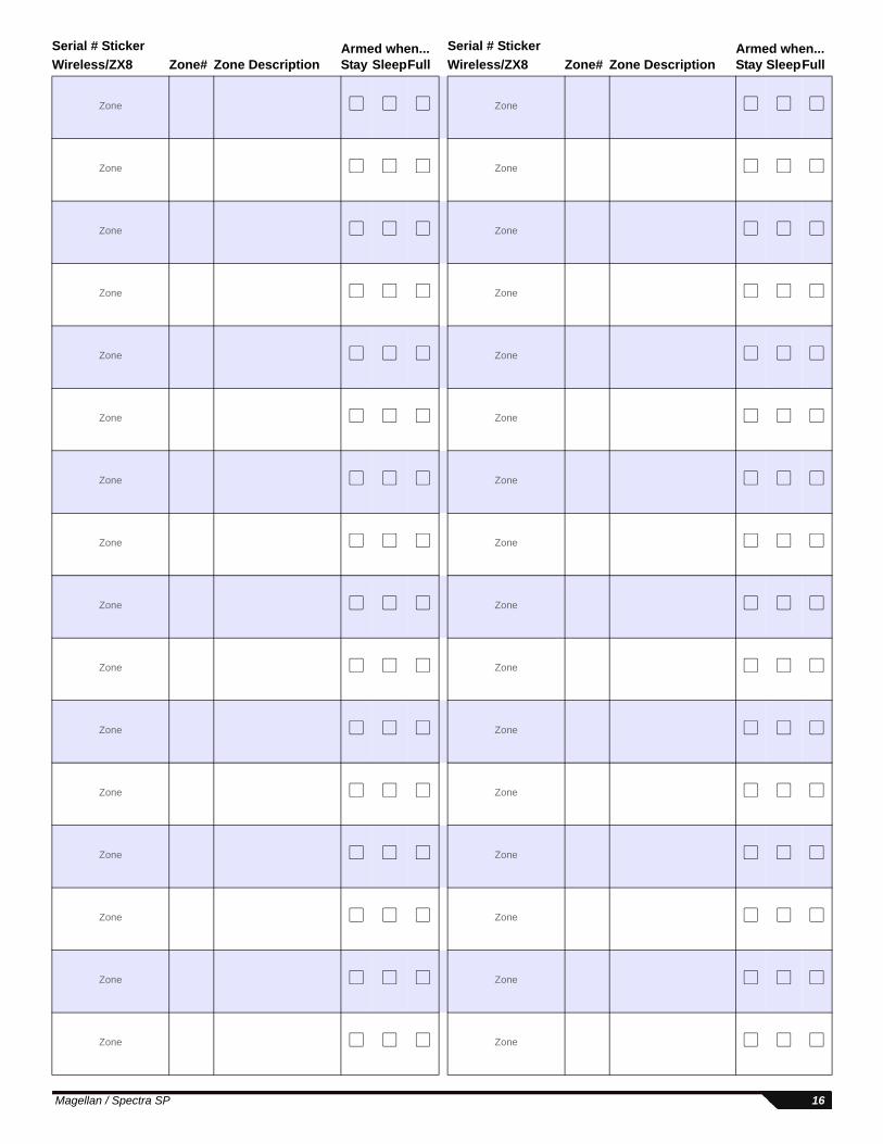
Serial # Sticker Armed when... Serial # Sticker Armed when...Wireless/ZX8 Zone# Zone Description Stay SleepFull Wireless/ZX8 Zone# Zone Description Stay SleepFull
Zone Zone
Zone Zone
Zone Zone
Zone Zone
Zone Zone
Zone Zone
Zone Zone
Zone Zone
Zone Zone
Zone Zone
Zone Zone
Zone Zone
Zone Zone
Zone Zone
Zone Zone
Zone Zone
Magellan / Spectra SP 16
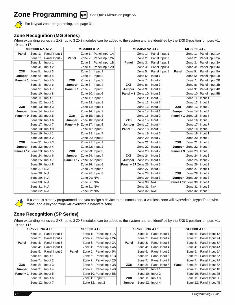
Zone Programming For keypad zone programming, see page 31.
Zone Recognition (MG Series)When expanding zones via ZX8, up to 3 ZX8 modules can be added to the system and are identified by the ZX8 3-position jumpers +1, +9 and +17.
If a zone is already programmed and you assign a device to the same zone, a wireless zone will overwrite a keypad/hardwire zone, and a keypad zone will overwrite a hardwire zone.
Zone Recognition (SP Series)When expanding zones via ZX8, up to 3 ZX8 modules can be added to the system and are identified by the ZX8 3-position jumpers +1, +9 and +17.
MG5000 No ATZ MG5000 ATZ MG5050 No ATZ MG5050 ATZPanel Zone 1: Panel Input 1 Zone 1: Panel Input 1A Zone 1: Panel Input 1 Zone 1: Panel Input 1A
Zone 2: Panel Input 2 Panel Zone 2: Panel Input 2A Zone 2: Panel Input 2 Zone 2: Panel Input 2AZone 3: Input 1 Zone 3: Panel Input 1B Panel Zone 3: Panel Input 3 Zone 3: Panel Input 3AZone 4: Input 2 Zone 4: Panel Input 2B Zone 4: Panel Input 4 Zone 4: Panel Input 4A
ZX8 Zone 5: Input 3 Zone 5: Input 1 Zone 5: Panel Input 5 Panel Zone 5: Panel Input 5AJumper Zone 6: Input 4 Zone 6: Input 2 Zone 6: Input 1 Zone 6: Panel Input 1B
Panel + 1 Zone 7: Input 5 ZX8 Zone 7: Input 3 Zone 7: Input 2 Zone 7: Panel Input 2BZone 8: Input 6 Jumper Zone 8: Input 4 ZX8 Zone 8: Input 3 Zone 8: Panel Input 3BZone 9: Input 7 Panel + 1 Zone 9: Input 5 Jumper Zone 9: Input 4 Zone 9: Panel Input 4BZone 10: Input 8 Zone 10: Input 6 Panel + 1 Zone 10: Input 5 Zone 10: Panel Input 5BZone 11: Input 1 Zone 11: Input 7 Zone 11: Input 6 Zone 11: Input 1Zone 12: Input 2 Zone 12: Input 8 Zone 12: Input 7 Zone 12: Input 2
ZX8 Zone 13: Input 3 Zone 13: Input 1 Zone 13: Input 8 ZX8 Zone 13: Input 3Jumper Zone 14: Input 4 Zone 14: Input 2 Zone 14: Input 1 Jumper Zone 14: Input 4
Panel + 9 Zone 15: Input 5 ZX8 Zone 15: Input 3 Zone 15: Input 2 Panel + 1 Zone 15: Input 5Zone 16: Input 6 Jumper Zone 16: Input 4 ZX8 Zone 16: Input 3 Zone 16: Input 6Zone 17: Input 7 Panel + 9 Zone 17: Input 5 Jumper Zone 17: Input 4 Zone 17: Input 7Zone 18: Input 8 Zone 18: Input 6 Panel + 9 Zone 18: Input 5 Zone 18: Input 8Zone 19: Input 1 Zone 19: Input 7 Zone 19: Input 6 Zone 19: Input 1Zone 20: Input 2 Zone 20: Input 8 Zone 20: Input 7 Zone 20: Input 2
ZX8 Zone 21: Input 3 Zone 21: Input 1 Zone 21: Input 8 ZX8 Zone 21: Input 3Jumper Zone 22: Input 4 Zone 22: Input 2 Zone 22: Input 1 Jumper Zone 22: Input 4
Panel + 17 Zone 23: Input 5 ZX8 Zone 23: Input 3 Zone 23: Input 2 Panel + 9 Zone 23: Input 5Zone 24: Input 6 Jumper Zone 24: Input 4 ZX8 Zone 24: Input 3 Zone 24: Input 6Zone 25: Input 7 Panel + 17 Zone 25: Input 5 Jumper Zone 25: Input 4 Zone 25: Input 7Zone 26: Input 8 Zone 26: Input 6 Panel + 17 Zone 26: Input 5 Zone 26: Input 8Zone 27: N/A Zone 27: Input 7 Zone 27: Input 6 Zone 27: Input 1Zone 28: N/A Zone 28: Input 8 Zone 28: Input 7 ZX8 Zone 28: Input 2Zone 29: N/A Zone 29: N/A Zone 29: Input 8 Jumper Zone 29: Input 3Zone 30: N/A Zone 30: N/A Zone 30: N/A Panel + 17 Zone 30: Input 4Zone 31: N/A Zone 31: N/A Zone 31: N/A Zone 31: Input 5Zone 32: N/A Zone 32: N/A Zone 32: N/A Zone 32: Input 6
SP5500 No ATZ SP5500 ATZ SP6000 No ATZ SP6000 ATZZone 1: Panel Input 1 Zone 1: Panel Input 1A Zone 1: Panel Input 1 Zone 1: Panel Input 1AZone 2: Panel Input 2 Zone 2: Panel Input 2A Zone 2: Panel Input 2 Zone 2: Panel Input 2A
Panel Zone 3: Panel Input 3 Zone 3: Panel Input 3A Panel Zone 3: Panel Input 3 Zone 3: Panel Input 3AZone 4: Panel Input 4 Zone 4: Panel Input 4A Zone 4: Panel Input 4 Zone 4: Panel Input 4AZone 5: Panel Input 5 Panel Zone 5: Panel Input 5A Zone 5: Panel Input 5 Zone 5: Panel Input 5AZone 6: Input 1 Zone 6: Panel Input 1B Zone 6: Panel Input 6 Zone 6: Panel Input 6AZone 7: Input 2 Zone 7: Panel Input 2B Zone 7: Panel Input 7 Zone 7: Panel Input 7A
ZX8 Zone 8: Input 3 Zone 8: Panel Input 3B ZX8 Zone 8: Panel Input 8 Panel Zone 8: Panel Input 8AJumper Zone 9: Input 4 Zone 9: Panel Input 4B Zone 9: Input 1 Zone 9: Panel Input 1B
Panel + 1 Zone 10: Input 5 Zone 10: Panel Input 5B Zone 10: Input 2 Zone 10: Panel Input 2BZone 11: Input 6 Zone 11: Input 1 ZX8 Zone 11: Input 3 Zone 11: Panel Input 3BZone 12: Input 7 Zone 12: Input 2 Jumper Zone 12: Input 4 Zone 12: Panel Input 4B
See Quick Menus on page 65
17 Programming Guide
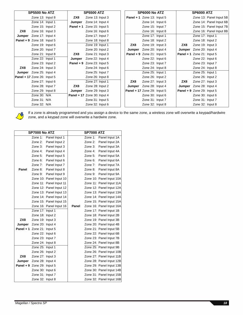
If a zone is already programmed and you assign a device to the same zone, a wireless zone will overwrite a keypad/hardwire zone, and a keypad zone will overwrite a hardwire zone.
Zone 13: Input 8 ZX8 Zone 13: Input 3 Panel + 1 Zone 13: Input 5 Zone 13: Panel Input 5BZone 14: Input 1 Jumper Zone 14: Input 4 Zone 14: Input 6 Zone 14: Panel Input 6BZone 15: Input 2 Panel + 1 Zone 15: Input 5 Zone 15: Input 7 Zone 15: Panel Input 7B
ZX8 Zone 16: Input 3 Zone 16: Input 6 Zone 16: Input 8 Zone 16: Panel Input 8BJumper Zone 17: Input 4 Zone 17: Input 7 Zone 17: Input 1 Zone 17: Input 1
Panel + 9 Zone 18: Input 5 Zone 18: Input 8 Zone 18: Input 2 Zone 18: Input 2Zone 19: Input 6 Zone 19: Input 1 ZX8 Zone 19: Input 3 ZX8 Zone 19: Input 3Zone 20: Input 7 Zone 20: Input 2 Jumper Zone 20: Input 4 Jumper Zone 20: Input 4Zone 21: Input 8 ZX8 Zone 21: Input 3 Panel + 9 Zone 21: Input 5 Panel + 1 Zone 21: Input 5Zone 22: Input 1 Jumper Zone 22: Input 4 Zone 22: Input 6 Zone 22: Input 6Zone 23: Input 2 Panel + 9 Zone 23: Input 5 Zone 23: Input 7 Zone 23: Input 7
ZX8 Zone 24: Input 3 Zone 24: Input 6 Zone 24: Input 8 Zone 24: Input 8Jumper Zone 25: Input 4 Zone 25: Input 7 Zone 25: Input 1 Zone 25: Input 1
Panel + 17 Zone 26: Input 5 Zone 26: Input 8 Zone 26: Input 2 Zone 26: Input 2Zone 27: Input 6 Zone 27: Input 1 ZX8 Zone 27: Input 3 ZX8 Zone 27: Input 3Zone 28: Input 7 ZX8 Zone 28: Input 2 Jumper Zone 28: Input 4 Jumper Zone 28: Input 4Zone 29: Input 8 Jumper Zone 29: Input 3 Panel + 17 Zone 29: Input 5 Panel + 9 Zone 29: Input 5Zone 30: N/A Panel + 17 Zone 30: Input 4 Zone 30: Input 6 Zone 30: Input 6Zone 31: N/A Zone 31: Input 5 Zone 31: Input 7 Zone 31: Input 7Zone 32: N/A Zone 32: Input 6 Zone 32: Input 8 Zone 32: Input 8
SP7000 No ATZ SP7000 ATZZone 1: Panel Input 1 Zone 1: Panel Input 1AZone 2: Panel Input 2 Zone 2: Panel Input 2AZone 3: Panel Input 3 Zone 3: Panel Input 3AZone 4: Panel Input 4 Zone 4: Panel Input 4AZone 5: Panel Input 5 Zone 5: Panel Input 5AZone 6: Panel Input 6 Zone 6: Panel Input 6AZone 7: Panel Input 7 Zone 7: Panel Input 7A
Panel Zone 8: Panel Input 8 Zone 8: Panel Input 8AZone 9: Panel Input 9 Zone 9: Panel Input 9AZone 10: Panel Input 10 Zone 10: Panel Input 10AZone 11: Panel Input 11 Zone 11: Panel Input 11AZone 12: Panel Input 12 Zone 12: Panel Input 12AZone 13: Panel Input 13 Zone 13: Panel Input 13AZone 14: Panel Input 14 Zone 14: Panel Input 14AZone 15: Panel Input 15 Zone 15: Panel Input 15AZone 16: Panel Input 16 Panel Zone 16: Panel Input 16AZone 17: Input 1 Zone 17: Panel Input 1BZone 18: Input 2 Zone 18: Panel Input 2B
ZX8 Zone 19: Input 3 Zone 19: Panel Input 3BJumper Zone 20: Input 4 Zone 20: Panel Input 4B
Panel + 1 Zone 21: Input 5 Zone 21: Panel Input 5BZone 22: Input 6 Zone 22: Panel Input 6BZone 23: Input 7 Zone 23: Panel Input 7BZone 24: Input 8 Zone 24: Panel Input 8BZone 25: Input 1 Zone 25: Panel Input 9BZone 26: Input 2 Zone 26: Panel Input 10B
ZX8 Zone 27: Input 3 Zone 27: Panel Input 11BJumper Zone 28: Input 4 Zone 28: Panel Input 12B
Panel + 9 Zone 29: Input 5 Zone 29: Panel Input 13BZone 30: Input 6 Zone 30: Panel Input 14BZone 31: Input 7 Zone 31: Panel Input 15BZone 32: Input 8 Zone 32: Panel Input 16B
SP5500 No ATZ SP5500 ATZ SP6000 No ATZ SP6000 ATZ
Magellan / Spectra SP 18
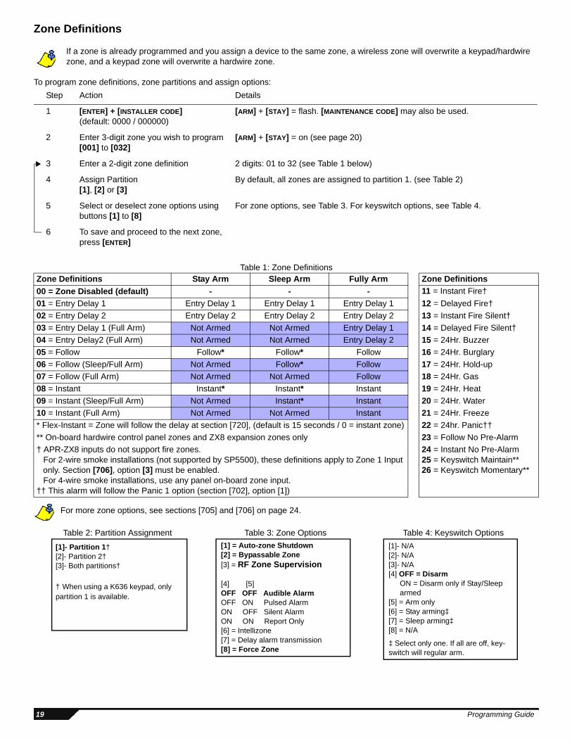
Zone Definitions
If a zone is already programmed and you assign a device to the same zone, a wireless zone will overwrite a keypad/hardwire zone, and a keypad zone will overwrite a hardwire zone.
To program zone definitions, zone partitions and assign options:
Table 1: Zone Definitions
For more zone options, see sections [705] and [706] on page 24.
Step Action Details
1 [ENTER] + [INSTALLER CODE](default: 0000 / 000000)
[ARM] + [STAY] = flash. [MAINTENANCE CODE] may also be used.
2 Enter 3-digit zone you wish to program[001] to [032]
[ARM] + [STAY] = on (see page 20)
3 Enter a 2-digit zone definition 2 digits: 01 to 32 (see Table 1 below)
4 Assign Partition [1], [2] or [3]
By default, all zones are assigned to partition 1. (see Table 2)
5 Select or deselect zone options using buttons [1] to [8]
For zone options, see Table 3. For keyswitch options, see Table 4.
6 To save and proceed to the next zone, press [ENTER]
Zone Definitions Stay Arm Sleep Arm Fully Arm Zone Definitions00 = Zone Disabled (default) - - - 11 = Instant Fire† 01 = Entry Delay 1 Entry Delay 1 Entry Delay 1 Entry Delay 1 12 = Delayed Fire†02 = Entry Delay 2 Entry Delay 2 Entry Delay 2 Entry Delay 2 13 = Instant Fire Silent†03 = Entry Delay 1 (Full Arm) Not Armed Not Armed Entry Delay 1 14 = Delayed Fire Silent†04 = Entry Delay2 (Full Arm) Not Armed Not Armed Entry Delay 2 15 = 24Hr. Buzzer05 = Follow Follow* Follow* Follow* 16 = 24Hr. Burglary06 = Follow (Sleep/Full Arm) Not Armed Follow* Follow 17 = 24Hr. Hold-up07 = Follow (Full Arm) Not Armed Not Armed Follow 18 = 24Hr. Gas08 = Instant Instant* Instant* Instant* 19 = 24Hr. Heat09 = Instant (Sleep/Full Arm) Not Armed Instant* Instant 20 = 24Hr. Water10 = Instant (Full Arm) Not Armed Not Armed Instant 21 = 24Hr. Freeze* Flex-Instant = Zone will follow the delay at section [720], (default is 15 seconds / 0 = instant zone) 22 = 24hr. Panic††** On-board hardwire control panel zones and ZX8 expansion zones only 23 = Follow No Pre-Alarm† APR-ZX8 inputs do not support fire zones.
For 2-wire smoke installations (not supported by SP5500), these definitions apply to Zone 1 Input only. Section [706], option [3] must be enabled.For 4-wire smoke installations, use any panel on-board zone input.
†† This alarm will follow the Panic 1 option (section [702], option [1])
24 = Instant No Pre-Alarm25 = Keyswitch Maintain**26 = Keyswitch Momentary**
[1]- N/A[2]- N/A[3]- N/A[4] OFF = Disarm
ON = Disarm only if Stay/Sleep armed
[5] = Arm only[6] = Stay arming‡[7] = Sleep arming‡[8] = N/A
‡ Select only one. If all are off, key-switch will regular arm.
[1] = Auto-zone Shutdown [2] = Bypassable Zone [3] = RF Zone Supervision
[4] [5]OFF OFF Audible AlarmOFF ON Pulsed AlarmON OFF Silent AlarmON ON Report Only[6] = Intellizone[7] = Delay alarm transmission[8] = Force Zone
[1]- Partition 1†[2]- Partition 2†[3]- Both partitions†
† When using a K636 keypad, only partition 1 is available.
Table 2: Partition Assignment Table 3: Zone Options Table 4: Keyswitch Options
19
Programming Guide
Refer to the Installer Quick Menu on page 65.
Section Zone* Zone Definition Partition Zone Options Section
Wireless SN or press tamper/learn
To delete, enter 000000
[001] Zone 1: __________________________ _____/_____ _____ 1 2 3 4 5 6 7 8 [061] ____/____/____/____/____/____
[002] Zone 2: __________________________ _____/_____ _____ 1 2 3 4 5 6 7 8 [062] ____/____/____/____/____/____
[003] Zone 3: __________________________ _____/_____ _____ 1 2 3 4 5 6 7 8 [063] ____/____/____/____/____/____
[004] Zone 4: __________________________ _____/_____ _____ 1 2 3 4 5 6 7 8 [064] ____/____/____/____/____/____
[005] Zone 5: __________________________ _____/_____ _____ 1 2 3 4 5 6 7 8 [065] ____/____/____/____/____/____
[006] Zone 6: __________________________ _____/_____ _____ 1 2 3 4 5 6 7 8 [066] ____/____/____/____/____/____
[007] Zone 7: __________________________ _____/_____ _____ 1 2 3 4 5 6 7 8 [067] ____/____/____/____/____/____
[008] Zone 8: __________________________ _____/_____ _____ 1 2 3 4 5 6 7 8 [068] ____/____/____/____/____/____
[009] Zone 9: __________________________ _____/_____ _____ 1 2 3 4 5 6 7 8 [069] ____/____/____/____/____/____
[010] Zone 10: _________________________ _____/_____ _____ 1 2 3 4 5 6 7 8 [070] ____/____/____/____/____/____
[011] Zone 11: _________________________ _____/_____ _____ 1 2 3 4 5 6 7 8 [071] ____/____/____/____/____/____
[012] Zone 12: _________________________ _____/_____ _____ 1 2 3 4 5 6 7 8 [072] ____/____/____/____/____/____
[013] Zone 13: _________________________ _____/_____ _____ 1 2 3 4 5 6 7 8 [073] ____/____/____/____/____/____
[014] Zone 14: _________________________ _____/_____ _____ 1 2 3 4 5 6 7 8 [074] ____/____/____/____/____/____
[015] Zone 15: _________________________ _____/_____ _____ 1 2 3 4 5 6 7 8 [075] ____/____/____/____/____/____
[016] Zone 16: _________________________ _____/_____ _____ 1 2 3 4 5 6 7 8 [076] ____/____/____/____/____/____
[017] Zone 17: _________________________ _____/_____ _____ 1 2 3 4 5 6 7 8 [077] ____/____/____/____/____/____
[018] Zone 18: _________________________ _____/_____ _____ 1 2 3 4 5 6 7 8 [078] ____/____/____/____/____/____
[019] Zone 19: _________________________ _____/_____ _____ 1 2 3 4 5 6 7 8 [079] ____/____/____/____/____/____
[020] Zone 20: _________________________ _____/_____ _____ 1 2 3 4 5 6 7 8 [080] ____/____/____/____/____/____
[021] Zone 21: _________________________ _____/_____ _____ 1 2 3 4 5 6 7 8 [081] ____/____/____/____/____/____
[022] Zone 22: _________________________ _____/_____ _____ 1 2 3 4 5 6 7 8 [082] ____/____/____/____/____/____
[023] Zone 23: _________________________ _____/_____ _____ 1 2 3 4 5 6 7 8 [083] ____/____/____/____/____/____
[024] Zone 24: _________________________ _____/_____ _____ 1 2 3 4 5 6 7 8 [084] ____/____/____/____/____/____
[025] Zone 25: _________________________ _____/_____ _____ 1 2 3 4 5 6 7 8 [085] ____/____/____/____/____/____
[026] Zone 26: _________________________ _____/_____ _____ 1 2 3 4 5 6 7 8 [086] ____/____/____/____/____/____
[027] Zone 27: _________________________ _____/_____ _____ 1 2 3 4 5 6 7 8 [087] ____/____/____/____/____/____
[028] Zone 28: _________________________ _____/_____ _____ 1 2 3 4 5 6 7 8 [088] ____/____/____/____/____/____
[029] Zone 29: _________________________ _____/_____ _____ 1 2 3 4 5 6 7 8 [089] ____/____/____/____/____/____
[030] Zone 30: _________________________ _____/_____ _____ 1 2 3 4 5 6 7 8 [090] ____/____/____/____/____/____
[031] Zone 31: _________________________ _____/_____ _____ 1 2 3 4 5 6 7 8 [091] ____/____/____/____/____/____
[032] Zone 32: _________________________ _____/_____ _____ 1 2 3 4 5 6 7 8 [092] ____/____/____/____/____/____
* See Zone Recognition tables on page 17.
Magellan / Spectra SP 20
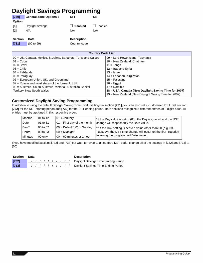
Daylight Savings Programming
Customized Daylight Saving ProgrammingIn addition to using the default Daylight Saving Time (DST) settings in section [731], you can also set a customized DST. Set section [732] for the DST starting period and [733] for the DST ending period. Both sections recognize 5 different entries of 2 digits each. All entries must be assigned in this respective order:
If you have modified sections [732] and [733] but want to revert to a standard DST code, change all of the settings in [732] and [733] to (00)
[730] General Zone Options 3 OFF ONOption[1] Daylight savings Disabled Enabled[2] N/A N/A N/A
Section Data Description[731] (00 to 99) Country code
Country Code List00 = US, Canada, Mexico, St.Johns, Bahamas, Turks and Caicos01 = Cuba02 = Brazil03 = Chile04 = Falklands05 = Paraguay06 = European Union, UK, and Greenland07 = Russia and most states of the former USSR08 = Australia- South Australia, Victoria, Australian Capital Territory, New South Wales
09 = Lord Howe Island- Tasmania10 = New Zealand, Chatham11 = Tonga12 = Iraq and Syria13 = Israel14 = Lebanon, Kirgizstan15 = Palestine16 = Egypt17 = Namibia18 = USA, Canada (New Daylight Saving Time for 2007)19 = New Zealand (New Daylight Saving Time for 2007)
Months 01 to 12 01 = January *If the Day value is set to (00), the Day is ignored and the DST change will respect only the Date value.
** If the Day setting is set to a value other than 00 (e.g. 03 - Tuesday), the DST time change will occur on the first 'Tuesday' following the programmed Date value.
Date 01 to 31 01 = First day of the monthDay** 00 to 07 00 = Default*, 01 = SundayHours 00 to 23 00 = MidnightMinutes 00 only 00 = 60 minutes or 1 hour
Section Data Description[732] __/__/__/__/__/__/__/__/__/__/ Daylight Savings Time Starting Period[733] __/__/__/__/__/__/__/__/__/__/ Daylight Savings Time Ending Period
21 Programming Guide
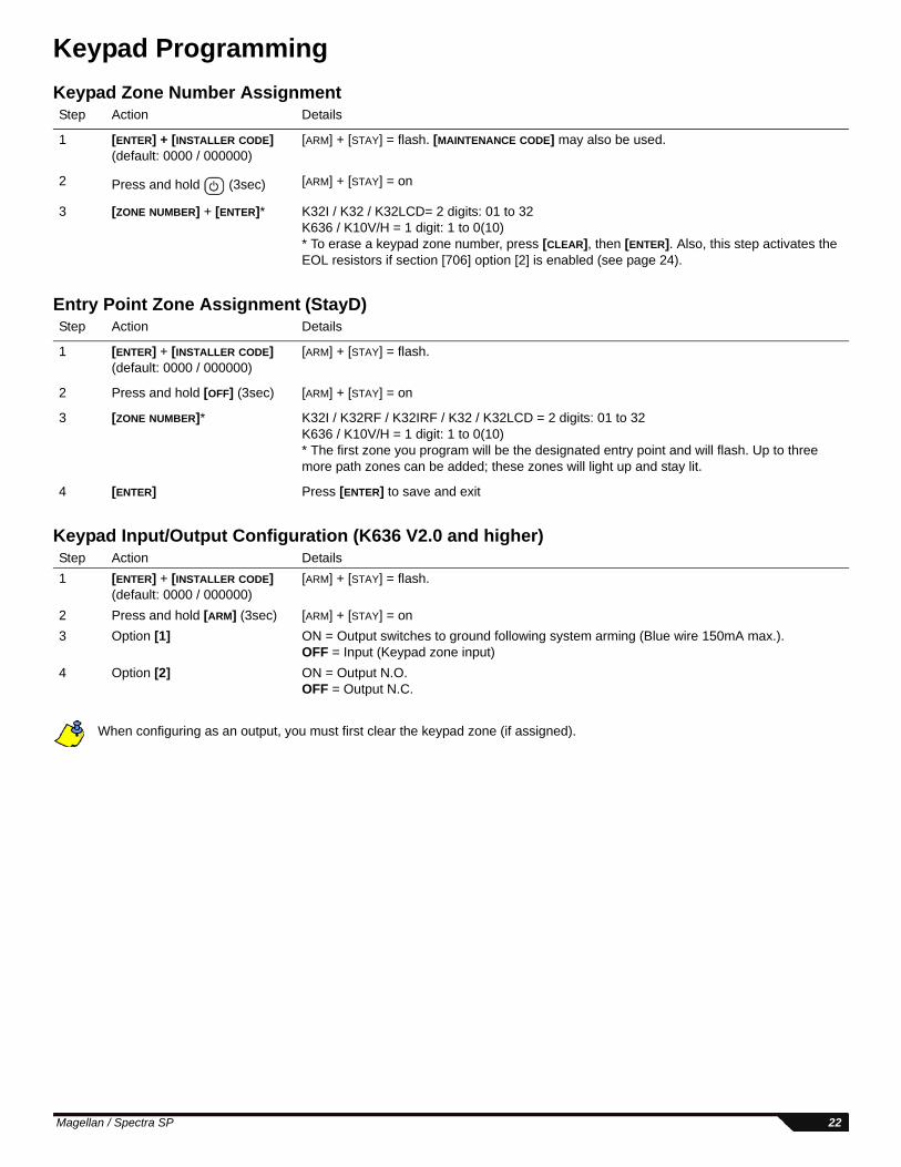
Keypad ProgrammingKeypad Zone Number Assignment
Entry Point Zone Assignment (StayD)
Keypad Input/Output Configuration (K636 V2.0 and higher)
When configuring as an output, you must first clear the keypad zone (if assigned).
Step Action Details
1 [ENTER] + [INSTALLER CODE](default: 0000 / 000000)
[ARM] + [STAY] = flash. [MAINTENANCE CODE] may also be used.
2 Press and hold (3sec) [ARM] + [STAY] = on
3 [ZONE NUMBER] + [ENTER]* K32I / K32 / K32LCD= 2 digits: 01 to 32K636 / K10V/H = 1 digit: 1 to 0(10)* To erase a keypad zone number, press [CLEAR], then [ENTER]. Also, this step activates the EOL resistors if section [706] option [2] is enabled (see page 24).
Step Action Details
1 [ENTER] + [INSTALLER CODE] (default: 0000 / 000000)
[ARM] + [STAY] = flash.
2 Press and hold [OFF] (3sec) [ARM] + [STAY] = on
3 [ZONE NUMBER]* K32I / K32RF / K32IRF / K32 / K32LCD = 2 digits: 01 to 32K636 / K10V/H = 1 digit: 1 to 0(10)* The first zone you program will be the designated entry point and will flash. Up to three more path zones can be added; these zones will light up and stay lit.
4 [ENTER] Press [ENTER] to save and exit
Step Action Details1 [ENTER] + [INSTALLER CODE]
(default: 0000 / 000000)[ARM] + [STAY] = flash.
2 Press and hold [ARM] (3sec) [ARM] + [STAY] = on3 Option [1] ON = Output switches to ground following system arming (Blue wire 150mA max.).
OFF = Input (Keypad zone input)4 Option [2] ON = Output N.O.
OFF = Output N.C.
Magellan / Spectra SP 22
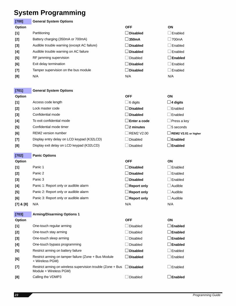
System Programming[700] General System OptionsOption OFF ON[1] Partitioning Disabled Enabled
[2] Battery charging (350mA or 700mA) 350mA 700mA
[3] Audible trouble warning (except AC failure) Disabled Enabled
[4] Audible trouble warning on AC failure Disabled Enabled
[5] RF jamming supervision Disabled Enabled
[6] Exit delay termination Disabled Enabled
[7] Tamper supervision on the bus module Disabled Enabled
[8] N/A N/A N/A
[701] General System OptionsOption OFF ON[1] Access code length 6 digits 4 digits
[2] Lock master code Disabled Enabled
[3] Confidential mode Disabled Enabled
[4] To exit confidential mode Enter a code Press a key
[5] Confidential mode timer 2 minutes 5 seconds
[6] REM2 version number REM2 V2.00 REM2 V2.01 or higher
[7] Display entry delay on LCD keypad (K32LCD) Disabled Enabled
[8] Display exit delay on LCD keypad (K32LCD) Disabled Enabled
[702] Panic OptionsOption OFF ON[1] Panic 1 Disabled Enabled
[2] Panic 2 Disabled Enabled
[3] Panic 3 Disabled Enabled
[4] Panic 1: Report only or audible alarm Report only Audible
[5] Panic 2: Report only or audible alarm Report only Audible
[6] Panic 3: Report only or audible alarm Report only Audible
[7] & [8] N/A N/A N/A
[703] Arming/Disarming Options 1Option OFF ON[1] One-touch regular arming Disabled Enabled
[2] One-touch stay arming Disabled Enabled
[3] One-touch sleep arming Disabled Enabled
[4] One-touch bypass programming Disabled Enabled
[5] Restrict arming on battery failure Disabled Enabled
[6] Restrict arming on tamper failure (Zone + Bus Module + Wireless PGM)
Disabled Enabled
[7] Restrict arming on wireless supervision trouble (Zone + Bus Module + Wireless PGM)
Disabled Enabled
[8] Calling the VDMP3 Disabled Enabled
23 Programming Guide
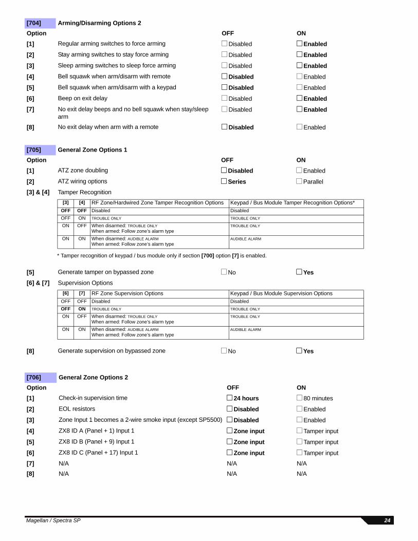
[704] Arming/Disarming Options 2Option OFF ON[1] Regular arming switches to force arming Disabled Enabled
[2] Stay arming switches to stay force arming Disabled Enabled
[3] Sleep arming switches to sleep force arming Disabled Enabled
[4] Bell squawk when arm/disarm with remote Disabled Enabled
[5] Bell squawk when arm/disarm with a keypad Disabled Enabled
[6] Beep on exit delay Disabled Enabled[7] No exit delay beeps and no bell squawk when stay/sleep
armDisabled Enabled
[8] No exit delay when arm with a remote Disabled Enabled
[705] General Zone Options 1Option OFF ON[1] ATZ zone doubling Disabled Enabled
[2] ATZ wiring options Series Parallel
[3] & [4] Tamper Recognition
[5] Generate tamper on bypassed zone No Yes[6] & [7] Supervision Options
[8] Generate supervision on bypassed zone No Yes
[706] General Zone Options 2Option OFF ON[1] Check-in supervision time 24 hours 80 minutes
[2] EOL resistors Disabled Enabled
[3] Zone Input 1 becomes a 2-wire smoke input (except SP5500) Disabled Enabled
[4] ZX8 ID A (Panel + 1) Input 1 Zone input Tamper input
[5] ZX8 ID B (Panel + 9) Input 1 Zone input Tamper input
[6] ZX8 ID C (Panel + 17) Input 1 Zone input Tamper input
[7] N/A N/A N/A
[8] N/A N/A N/A
[3] [4] RF Zone/Hardwired Zone Tamper Recognition Options Keypad / Bus Module Tamper Recognition Options*OFF OFF Disabled Disabled OFF ON TROUBLE ONLY TROUBLE ONLY
ON OFF When disarmed: TROUBLE ONLYWhen armed: Follow zone’s alarm type
TROUBLE ONLY
ON ON When disarmed: AUDIBLE ALARMWhen armed: Follow zone’s alarm type
AUDIBLE ALARM
* Tamper recognition of keypad / bus module only if section [700] option [7] is enabled.
[6] [7] RF Zone Supervision Options Keypad / Bus Module Supervision OptionsOFF OFF Disabled Disabled OFF ON TROUBLE ONLY TROUBLE ONLY
ON OFF When disarmed: TROUBLE ONLYWhen armed: Follow zone’s alarm type
TROUBLE ONLY
ON ON When disarmed: AUDIBLE ALARMWhen armed: Follow zone’s alarm type
AUDIBLE ALARM
Magellan / Spectra SP 24

Other Settings and Modes
Partition Programming
Section Description[950] Reset all programmable sections to factory default values [955] Clear bus module trouble (remove disconnected module from the bus)[960] Remote control serial number display (press any button on the assigned remote, then press [ENTER] to view the next digit)[970] Download memory key into panel (see the Reference & Installation Manual)[975] Upload panel into the memory key (see the Reference & Installation Manual)[980] Display version number of the panel (press [ENTER] to view the next digit)
[741] Partition 1 OptionsOption OFF ON[1] Auto-arm on time Disabled Enabled[2] Auto-arm on no movement Disabled Enabled
[3]& [4]
Auto-arm arming mode See Table See Table
[5] Switch to stay arming if no zone entry delay is opened Disabled Enabled[6] Follow zones become entry delay 2 when delay zone is bypassed Disabled Enabled[7]& [8] N/A N/A N/A
[742] Partition 2 OptionsOption OFF ON[1] Auto-arm on time Disabled Enabled[2] Auto-arm on no movement Disabled Enabled
[3]& [4]
Auto-arm arming mode See Table See Table
[5] Switch to stay arming if no entry delay is opened Disabled Enabled[6] Follow zones become entry delay 2 when delay zone is bypassed Disabled Enabled[7]& [8] N/A N/A N/A
[3] [4]OFF OFF RegularOFF ON SleepON OFF Stay
[3] [4]OFF OFF RegularOFF ON SleepON OFF Stay
25 Programming Guide
TimersZone Timers (MG Series)
Zone Timers (SP Series)
System Timers
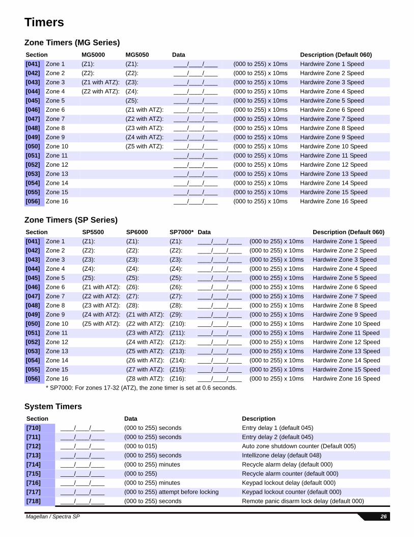
Section MG5000 MG5050 Data Description (Default 060)[041] Zone 1 (Z1): (Z1): ____/____/____ (000 to 255) x 10ms Hardwire Zone 1 Speed [042] Zone 2 (Z2): (Z2): ____/____/____ (000 to 255) x 10ms Hardwire Zone 2 Speed[043] Zone 3 (Z1 with ATZ): (Z3): ____/____/____ (000 to 255) x 10ms Hardwire Zone 3 Speed [044] Zone 4 (Z2 with ATZ): (Z4): ____/____/____ (000 to 255) x 10ms Hardwire Zone 4 Speed [045] Zone 5 (Z5): ____/____/____ (000 to 255) x 10ms Hardwire Zone 5 Speed [046] Zone 6 (Z1 with ATZ): ____/____/____ (000 to 255) x 10ms Hardwire Zone 6 Speed[047] Zone 7 (Z2 with ATZ): ____/____/____ (000 to 255) x 10ms Hardwire Zone 7 Speed [048] Zone 8 (Z3 with ATZ): ____/____/____ (000 to 255) x 10ms Hardwire Zone 8 Speed [049] Zone 9 (Z4 with ATZ): ____/____/____ (000 to 255) x 10ms Hardwire Zone 9 Speed[050] Zone 10 (Z5 with ATZ): ____/____/____ (000 to 255) x 10ms Hardwire Zone 10 Speed [051] Zone 11 ____/____/____ (000 to 255) x 10ms Hardwire Zone 11 Speed [052] Zone 12 ____/____/____ (000 to 255) x 10ms Hardwire Zone 12 Speed [053] Zone 13 ____/____/____ (000 to 255) x 10ms Hardwire Zone 13 Speed [054] Zone 14 ____/____/____ (000 to 255) x 10ms Hardwire Zone 14 Speed [055] Zone 15 ____/____/____ (000 to 255) x 10ms Hardwire Zone 15 Speed [056] Zone 16 ____/____/____ (000 to 255) x 10ms Hardwire Zone 16 Speed
Section SP5500 SP6000 SP7000* Data Description (Default 060)[041] Zone 1 (Z1): (Z1): (Z1): ____/____/____ (000 to 255) x 10ms Hardwire Zone 1 Speed [042] Zone 2 (Z2): (Z2): (Z2): ____/____/____ (000 to 255) x 10ms Hardwire Zone 2 Speed[043] Zone 3 (Z3): (Z3): (Z3): ____/____/____ (000 to 255) x 10ms Hardwire Zone 3 Speed [044] Zone 4 (Z4): (Z4): (Z4): ____/____/____ (000 to 255) x 10ms Hardwire Zone 4 Speed [045] Zone 5 (Z5): (Z5): (Z5): ____/____/____ (000 to 255) x 10ms Hardwire Zone 5 Speed [046] Zone 6 (Z1 with ATZ): (Z6): (Z6): ____/____/____ (000 to 255) x 10ms Hardwire Zone 6 Speed[047] Zone 7 (Z2 with ATZ): (Z7): (Z7): ____/____/____ (000 to 255) x 10ms Hardwire Zone 7 Speed [048] Zone 8 (Z3 with ATZ): (Z8): (Z8): ____/____/____ (000 to 255) x 10ms Hardwire Zone 8 Speed [049] Zone 9 (Z4 with ATZ): (Z1 with ATZ): (Z9): ____/____/____ (000 to 255) x 10ms Hardwire Zone 9 Speed[050] Zone 10 (Z5 with ATZ): (Z2 with ATZ): (Z10): ____/____/____ (000 to 255) x 10ms Hardwire Zone 10 Speed [051] Zone 11 (Z3 with ATZ): (Z11): ____/____/____ (000 to 255) x 10ms Hardwire Zone 11 Speed [052] Zone 12 (Z4 with ATZ): (Z12): ____/____/____ (000 to 255) x 10ms Hardwire Zone 12 Speed [053] Zone 13 (Z5 with ATZ): (Z13): ____/____/____ (000 to 255) x 10ms Hardwire Zone 13 Speed [054] Zone 14 (Z6 with ATZ): (Z14): ____/____/____ (000 to 255) x 10ms Hardwire Zone 14 Speed [055] Zone 15 (Z7 with ATZ): (Z15): ____/____/____ (000 to 255) x 10ms Hardwire Zone 15 Speed [056] Zone 16 (Z8 with ATZ): (Z16): ____/____/____ (000 to 255) x 10ms Hardwire Zone 16 Speed
* SP7000: For zones 17-32 (ATZ), the zone timer is set at 0.6 seconds.
Section Data Description[710] ____/____/____ (000 to 255) seconds Entry delay 1 (default 045)[711] ____/____/____ (000 to 255) seconds Entry delay 2 (default 045)[712] ____/____/____ (000 to 015) Auto zone shutdown counter (Default 005)[713] ____/____/____ (000 to 255) seconds Intellizone delay (default 048)[714] ____/____/____ (000 to 255) minutes Recycle alarm delay (default 000)[715] ____/____/____ (000 to 255) Recycle alarm counter (default 000)[716] ____/____/____ (000 to 255) minutes Keypad lockout delay (default 000)[717] ____/____/____ (000 to 255) attempt before locking Keypad lockout counter (default 000)[718] ____/____/____ (000 to 255) seconds Remote panic disarm lock delay (default 000)
Magellan / Spectra SP 26
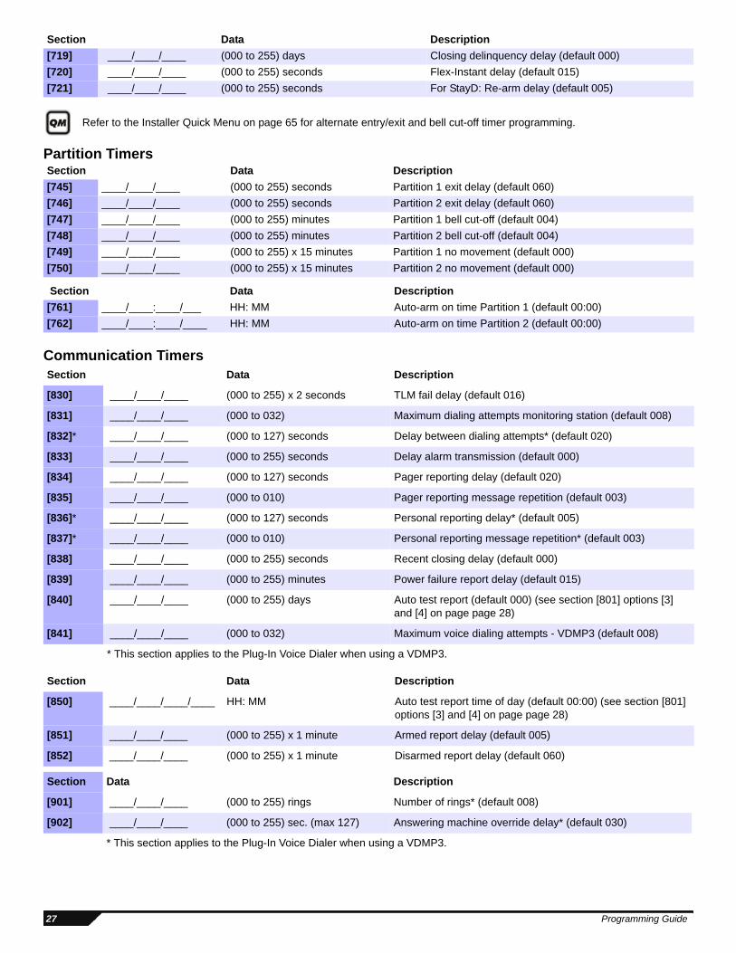
Refer to the Installer Quick Menu on page 65 for alternate entry/exit and bell cut-off timer programming.
Partition Timers
Communication Timers
[719] ____/____/____ (000 to 255) days Closing delinquency delay (default 000)[720] ____/____/____ (000 to 255) seconds Flex-Instant delay (default 015)[721] ____/____/____ (000 to 255) seconds For StayD: Re-arm delay (default 005)
Section Data Description[745] ____/____/____ (000 to 255) seconds Partition 1 exit delay (default 060)[746] ____/____/____ (000 to 255) seconds Partition 2 exit delay (default 060)[747] ____/____/____ (000 to 255) minutes Partition 1 bell cut-off (default 004)[748] ____/____/____ (000 to 255) minutes Partition 2 bell cut-off (default 004)[749] ____/____/____ (000 to 255) x 15 minutes Partition 1 no movement (default 000)[750] ____/____/____ (000 to 255) x 15 minutes Partition 2 no movement (default 000)
Section Data Description[761] ____/____:____/___ HH: MM Auto-arm on time Partition 1 (default 00:00)[762] ____/____:____/____ HH: MM Auto-arm on time Partition 2 (default 00:00)
Section Data Description
[830] ____/____/____ (000 to 255) x 2 seconds TLM fail delay (default 016)
[831] ____/____/____ (000 to 032) Maximum dialing attempts monitoring station (default 008)
[832]* ____/____/____ (000 to 127) seconds Delay between dialing attempts* (default 020)
[833] ____/____/____ (000 to 255) seconds Delay alarm transmission (default 000)
[834] ____/____/____ (000 to 127) seconds Pager reporting delay (default 020)
[835] ____/____/____ (000 to 010) Pager reporting message repetition (default 003)
[836]* ____/____/____ (000 to 127) seconds Personal reporting delay* (default 005)
[837]* ____/____/____ (000 to 010) Personal reporting message repetition* (default 003)
[838] ____/____/____ (000 to 255) seconds Recent closing delay (default 000)
[839] ____/____/____ (000 to 255) minutes Power failure report delay (default 015)
[840] ____/____/____ (000 to 255) days Auto test report (default 000) (see section [801] options [3] and [4] on page page 28)
[841] ____/____/____ (000 to 032) Maximum voice dialing attempts - VDMP3 (default 008)
* This section applies to the Plug-In Voice Dialer when using a VDMP3.
Section Data Description
[850] ____/____/____/____ HH: MM Auto test report time of day (default 00:00) (see section [801] options [3] and [4] on page page 28)
[851] ____/____/____ (000 to 255) x 1 minute Armed report delay (default 005)
[852] ____/____/____ (000 to 255) x 1 minute Disarmed report delay (default 060)
Section Data Description
[901] ____/____/____ (000 to 255) rings Number of rings* (default 008)
[902] ____/____/____ (000 to 255) sec. (max 127) Answering machine override delay* (default 030)
* This section applies to the Plug-In Voice Dialer when using a VDMP3.
Section Data Description
27 Programming Guide
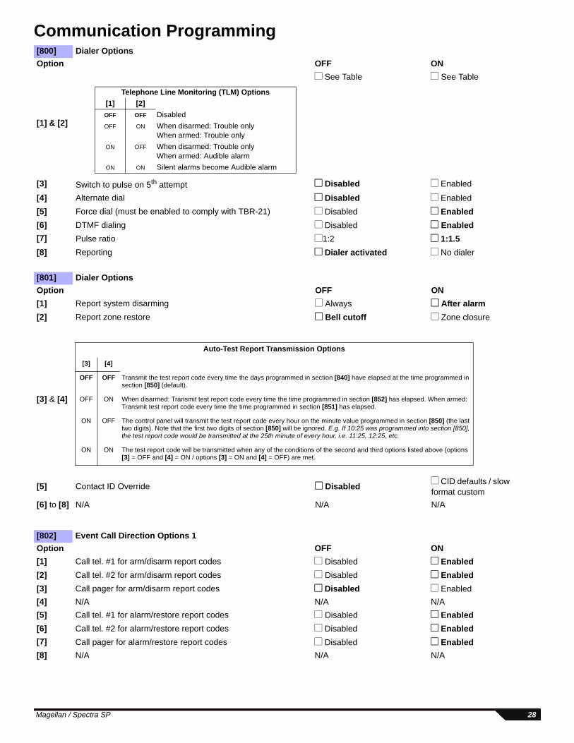
Communication Programming[800] Dialer OptionsOption OFF ON
[1] & [2]
See Table See Table
[3] Switch to pulse on 5th attempt Disabled Enabled
[4] Alternate dial Disabled Enabled[5] Force dial (must be enabled to comply with TBR-21) Disabled Enabled[6] DTMF dialing Disabled Enabled[7] Pulse ratio 1:2 1:1.5[8] Reporting Dialer activated No dialer
[801] Dialer OptionsOption OFF ON[1] Report system disarming Always After alarm[2] Report zone restore Bell cutoff Zone closure
[3] & [4]
[5] Contact ID Override Disabled CID defaults / slow format custom
[6] to [8] N/A N/A N/A
[802] Event Call Direction Options 1Option OFF ON[1] Call tel. #1 for arm/disarm report codes Disabled Enabled[2] Call tel. #2 for arm/disarm report codes Disabled Enabled[3] Call pager for arm/disarm report codes Disabled Enabled[4] N/A N/A N/A[5] Call tel. #1 for alarm/restore report codes Disabled Enabled[6] Call tel. #2 for alarm/restore report codes Disabled Enabled[7] Call pager for alarm/restore report codes Disabled Enabled[8] N/A N/A N/A
Telephone Line Monitoring (TLM) Options[1] [2]OFF OFF DisabledOFF ON When disarmed: Trouble only
When armed: Trouble onlyON OFF When disarmed: Trouble only
When armed: Audible alarmON ON Silent alarms become Audible alarm
Auto-Test Report Transmission Options
[3] [4]
OFF OFF Transmit the test report code every time the days programmed in section [840] have elapsed at the time programmed in section [850] (default).
OFF ON When disarmed: Transmit test report code every time the time programmed in section [852] has elapsed. When armed: Transmit test report code every time the time programmed in section [851] has elapsed.
ON OFF The control panel will transmit the test report code every hour on the minute value programmed in section [850] (the last two digits). Note that the first two digits of section [850] will be ignored. E.g. If 10:25 was programmed into section [850], the test report code would be transmitted at the 25th minute of every hour, i.e. 11:25, 12:25, etc.
ON ON The test report code will be transmitted when any of the conditions of the second and third options listed above (options [3] = OFF and [4] = ON / options [3] = ON and [4] = OFF) are met.
Magellan / Spectra SP 28
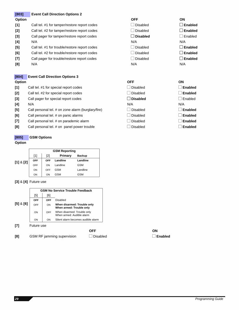
[803] Event Call Direction Options 2Option OFF ON[1] Call tel. #1 for tamper/restore report codes Disabled Enabled[2] Call tel. #2 for tamper/restore report codes Disabled Enabled[3] Call pager for tamper/restore report codes Disabled Enabled[4] N/A N/A N/A[5] Call tel. #1 for trouble/restore report codes Disabled Enabled[6] Call tel. #2 for trouble/restore report codes Disabled Enabled[7] Call pager for trouble/restore report codes Disabled Enabled[8] N/A N/A N/A
[804] Event Call Direction Options 3Option OFF ON[1] Call tel. #1 for special report codes Disabled Enabled[2] Call tel. #2 for special report codes Disabled Enabled[3] Call pager for special report codes Disabled Enabled[4] N/A N/A N/A[5] Call personal tel. # on zone alarm (burglary/fire) Disabled Enabled[6] Call personal tel. # on panic alarms Disabled Enabled[7] Call personal tel. # on parademic alarm Disabled Enabled[8] Call personal tel. # on panel power trouble Disabled Enabled
[805] GSM Options Option
[1] & [2]
[3] & [4] Future use
[5] & [6]
[7] Future useOFF ON
[8] GSM RF jamming supervision Disabled Enabled
GSM Reporting[1] [2] Primary Backup
OFF OFF Landline Landline
OFF ON Landline GSM
ON OFF GSM Landline
ON ON GSM GSM
GSM No Service Trouble Feedback[5] [6]
OFF OFF Disabled
OFF ON When disarmed: Trouble onlyWhen armed: Trouble only
ON OFF When disarmed: Trouble onlyWhen armed: Audible alarm
ON ON Silent alarm becomes audible alarm
29 Programming Guide
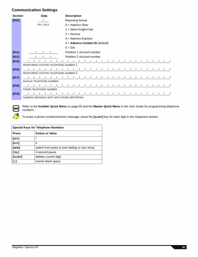
Communication Settings
Refer to the Installer Quick Menu on page 65 and the Master Quick Menu in the User Guide for programming telephone numbers.
To erase a phone number/numeric message, press the [SLEEP] key for each digit in the respective section.
Section Data Description[810] ___/___ Reporting format
TEL1 TEL2 0 = Ademco Slow1 = Silent Knight Fast2 = Sescoa3 = Ademco Express4 = Ademco Contact ID (default)5 = SIA
[811] ____/____/____/____ Partition 1 Account number[812] ____/____/____/____ Partition 2 Account number[815] ___/___/___/___/___/___/___/___/___/___/___/___/___/___/___/___/___/___/___/___/___/___/___/___/___/___/
MONITORING STATION TELEPHONE NUMBER 1[816] ___/___/___/___/___/___/___/___/___/___/___/___/___/___/___/___/___/___/___/___/___/___/___/___/___/___/
MONITORING STATION TELEPHONE NUMBER 2[817] ___/___/___/___/___/___/___/___/___/___/___/___/___/___/___/___/___/___/___/___/___/___/___/___/___/___/
BACKUP TELEPHONE NUMBER [818] ___/___/___/___/___/___/___/___/___/___/___/___/___/___/___/___/___/___/___/___/___/___/___/___/___/___/
PAGER TELEPHONE NUMBER
[819] ___/___/___/___/___/___/___/___/___/___/___/___/___/___/___/___/___/___/___/___/___/___/___/___/___/___/ NUMERIC MESSAGE SENT WITH PAGER REPORTING
Special Keys for Telephone Numbers
Press Action or Value
[OFF] *[BYP] #[MEM] switch from pulse to tone dialing or vice versa[TBL] 4-second pause[SLEEP] deletes current digit[ ] inserts blank space
Magellan / Spectra SP 30
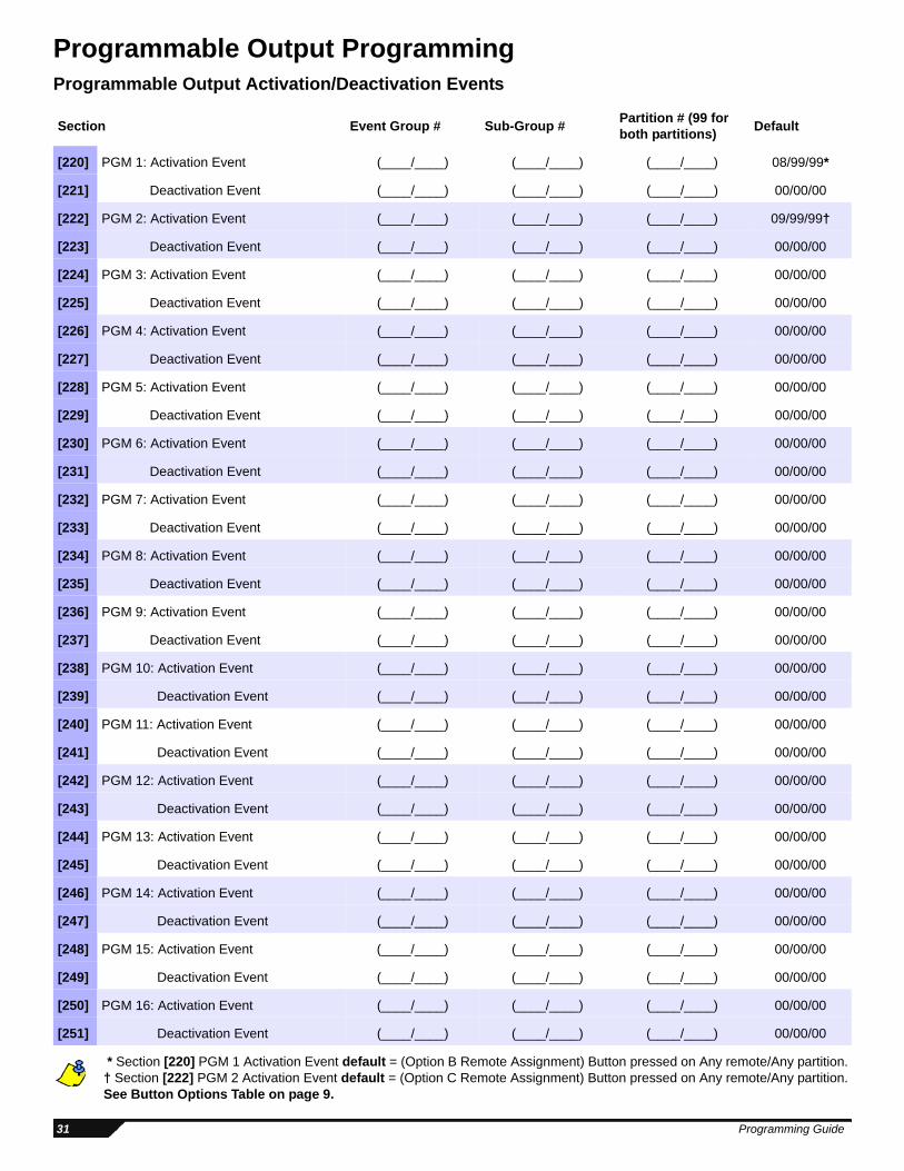
Programmable Output ProgrammingProgrammable Output Activation/Deactivation Events
* Section [220] PGM 1 Activation Event default = (Option B Remote Assignment) Button pressed on Any remote/Any partition. † Section [222] PGM 2 Activation Event default = (Option C Remote Assignment) Button pressed on Any remote/Any partition. See Button Options Table on page 9.
Section Event Group # Sub-Group # Partition # (99 for both partitions) Default
[220] PGM 1: Activation Event (____/____) (____/____) (____/____) 08/99/99*
[221] Deactivation Event (____/____) (____/____) (____/____) 00/00/00
[222] PGM 2: Activation Event (____/____) (____/____) (____/____) 09/99/99†
[223] Deactivation Event (____/____) (____/____) (____/____) 00/00/00
[224] PGM 3: Activation Event (____/____) (____/____) (____/____) 00/00/00
[225] Deactivation Event (____/____) (____/____) (____/____) 00/00/00
[226] PGM 4: Activation Event (____/____) (____/____) (____/____) 00/00/00
[227] Deactivation Event (____/____) (____/____) (____/____) 00/00/00
[228] PGM 5: Activation Event (____/____) (____/____) (____/____) 00/00/00
[229] Deactivation Event (____/____) (____/____) (____/____) 00/00/00
[230] PGM 6: Activation Event (____/____) (____/____) (____/____) 00/00/00
[231] Deactivation Event (____/____) (____/____) (____/____) 00/00/00
[232] PGM 7: Activation Event (____/____) (____/____) (____/____) 00/00/00
[233] Deactivation Event (____/____) (____/____) (____/____) 00/00/00
[234] PGM 8: Activation Event (____/____) (____/____) (____/____) 00/00/00
[235] Deactivation Event (____/____) (____/____) (____/____) 00/00/00
[236] PGM 9: Activation Event (____/____) (____/____) (____/____) 00/00/00
[237] Deactivation Event (____/____) (____/____) (____/____) 00/00/00
[238] PGM 10: Activation Event (____/____) (____/____) (____/____) 00/00/00
[239] Deactivation Event (____/____) (____/____) (____/____) 00/00/00
[240] PGM 11: Activation Event (____/____) (____/____) (____/____) 00/00/00
[241] Deactivation Event (____/____) (____/____) (____/____) 00/00/00
[242] PGM 12: Activation Event (____/____) (____/____) (____/____) 00/00/00
[243] Deactivation Event (____/____) (____/____) (____/____) 00/00/00
[244] PGM 13: Activation Event (____/____) (____/____) (____/____) 00/00/00
[245] Deactivation Event (____/____) (____/____) (____/____) 00/00/00
[246] PGM 14: Activation Event (____/____) (____/____) (____/____) 00/00/00
[247] Deactivation Event (____/____) (____/____) (____/____) 00/00/00
[248] PGM 15: Activation Event (____/____) (____/____) (____/____) 00/00/00
[249] Deactivation Event (____/____) (____/____) (____/____) 00/00/00
[250] PGM 16: Activation Event (____/____) (____/____) (____/____) 00/00/00
[251] Deactivation Event (____/____) (____/____) (____/____) 00/00/00
31 Programming Guide
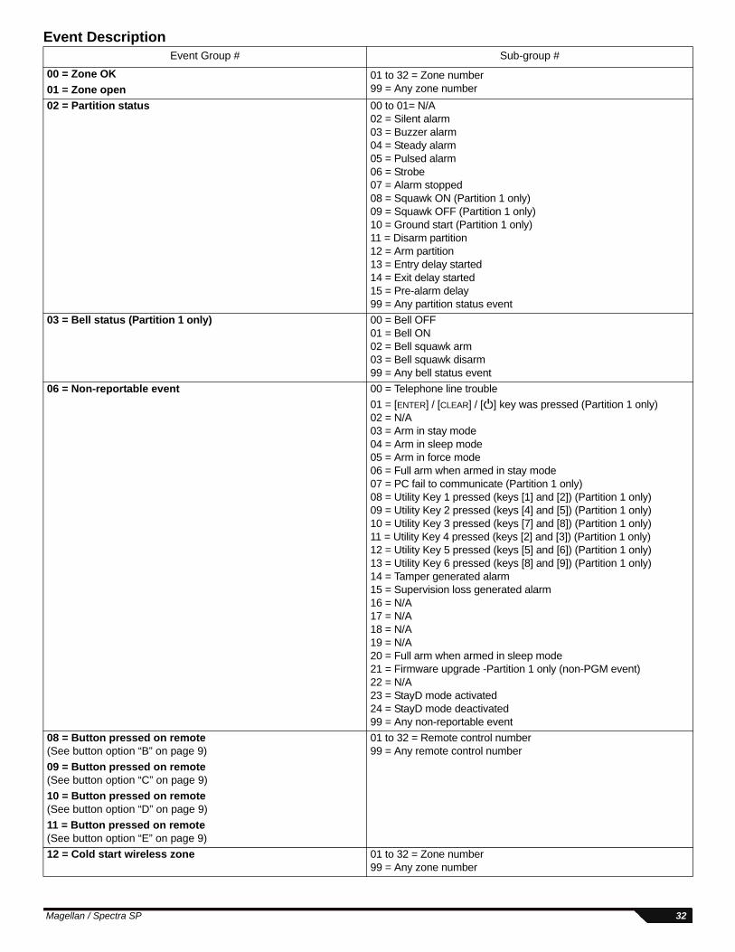
Event DescriptionEvent Group # Sub-group #
00 = Zone OK 01 to 32 = Zone number99 = Any zone number01 = Zone open
02 = Partition status 00 to 01= N/A02 = Silent alarm03 = Buzzer alarm04 = Steady alarm05 = Pulsed alarm06 = Strobe07 = Alarm stopped08 = Squawk ON (Partition 1 only)09 = Squawk OFF (Partition 1 only)10 = Ground start (Partition 1 only)11 = Disarm partition12 = Arm partition13 = Entry delay started14 = Exit delay started15 = Pre-alarm delay99 = Any partition status event
03 = Bell status (Partition 1 only) 00 = Bell OFF 01 = Bell ON 02 = Bell squawk arm 03 = Bell squawk disarm 99 = Any bell status event
06 = Non-reportable event 00 = Telephone line trouble01 = [ENTER] / [CLEAR] / [ ] key was pressed (Partition 1 only)02 = N/A03 = Arm in stay mode04 = Arm in sleep mode05 = Arm in force mode06 = Full arm when armed in stay mode07 = PC fail to communicate (Partition 1 only)08 = Utility Key 1 pressed (keys [1] and [2]) (Partition 1 only)09 = Utility Key 2 pressed (keys [4] and [5]) (Partition 1 only)10 = Utility Key 3 pressed (keys [7] and [8]) (Partition 1 only)11 = Utility Key 4 pressed (keys [2] and [3]) (Partition 1 only)12 = Utility Key 5 pressed (keys [5] and [6]) (Partition 1 only)13 = Utility Key 6 pressed (keys [8] and [9]) (Partition 1 only)14 = Tamper generated alarm15 = Supervision loss generated alarm16 = N/A17 = N/A18 = N/A19 = N/A20 = Full arm when armed in sleep mode21 = Firmware upgrade -Partition 1 only (non-PGM event)22 = N/A23 = StayD mode activated24 = StayD mode deactivated99 = Any non-reportable event
08 = Button pressed on remote(See button option “B” on page 9)
01 to 32 = Remote control number99 = Any remote control number
09 = Button pressed on remote(See button option “C” on page 9)10 = Button pressed on remote(See button option “D” on page 9)11 = Button pressed on remote(See button option “E” on page 9)12 = Cold start wireless zone 01 to 32 = Zone number
99 = Any zone number
Magellan / Spectra SP 32
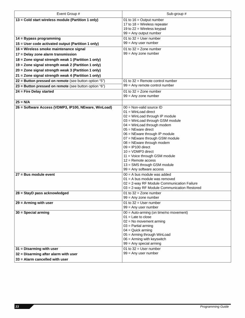
13 = Cold start wireless module (Partition 1 only) 01 to 16 = Output number17 to 18 = Wireless repeater19 to 22 = Wireless keypad99 = Any output number
14 = Bypass programming 01 to 32 = User number99 = Any user number15 = User code activated output (Partition 1 only)
16 = Wireless smoke maintenance signal 01 to 32 = Zone number99 = Any zone number17 = Delay zone alarm transmission
18 = Zone signal strength weak 1 (Partition 1 only)19 = Zone signal strength weak 2 (Partition 1 only)20 = Zone signal strength weak 3 (Partition 1 only)21 = Zone signal strength weak 4 (Partition 1 only)22 = Button pressed on remote (see button option “5”) 01 to 32 = Remote control number
99 = Any remote control number23 = Button pressed on remote (see button option “6”)24 = Fire Delay started 01 to 32 = Zone number
99 = Any zone number
25 = N/A26 = Software Access (VDMP3, IP100, NEware, WinLoad) 00 = Non-valid source ID
01 = WinLoad direct02 = WinLoad through IP module03 = WinLoad through GSM module04 = WinLoad through modem05 = NEware direct06 = NEware through IP module07 = NEware through GSM module08 = NEware through modem09 = IP100 direct10 = VDMP3 direct11 = Voice through GSM module12 = Remote access13 = SMS through GSM module99 = Any software access
27 = Bus module event 00 = A bus module was added01 = A bus module was removed02 = 2-way RF Module Communication Failure03 = 2-way RF Module Communication Restored
28 = StayD pass acknowledged 01 to 32 = Zone number99 = Any zone number
29 = Arming with user 01 to 32 = User number99 = Any user number
30 = Special arming 00 = Auto-arming (on time/no movement)01 = Late to close02 = No movement arming03 = Partial arming04 = Quick arming05 = Arming through WinLoad06 = Arming with keyswitch99 = Any special arming
31 = Disarming with user 01 to 32 = User number99 = Any user number32 = Disarming after alarm with user
33 = Alarm cancelled with user
Event Group # Sub-group #
33 Programming Guide
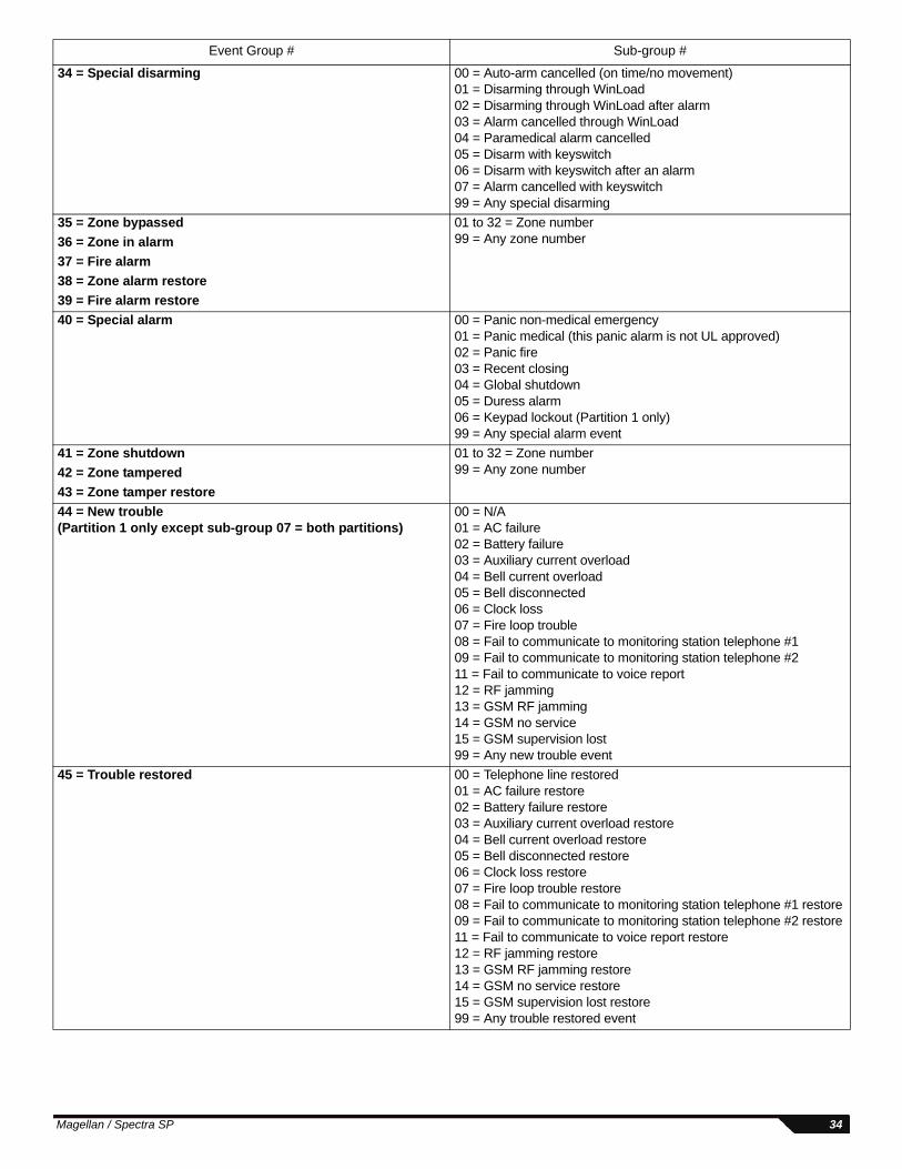
34 = Special disarming 00 = Auto-arm cancelled (on time/no movement)01 = Disarming through WinLoad02 = Disarming through WinLoad after alarm03 = Alarm cancelled through WinLoad04 = Paramedical alarm cancelled05 = Disarm with keyswitch06 = Disarm with keyswitch after an alarm07 = Alarm cancelled with keyswitch99 = Any special disarming
35 = Zone bypassed 01 to 32 = Zone number99 = Any zone number36 = Zone in alarm
37 = Fire alarm38 = Zone alarm restore39 = Fire alarm restore40 = Special alarm 00 = Panic non-medical emergency
01 = Panic medical (this panic alarm is not UL approved)02 = Panic fire03 = Recent closing04 = Global shutdown05 = Duress alarm 06 = Keypad lockout (Partition 1 only)99 = Any special alarm event
41 = Zone shutdown 01 to 32 = Zone number99 = Any zone number42 = Zone tampered
43 = Zone tamper restore44 = New trouble (Partition 1 only except sub-group 07 = both partitions)
00 = N/A01 = AC failure 02 = Battery failure 03 = Auxiliary current overload 04 = Bell current overload 05 = Bell disconnected 06 = Clock loss 07 = Fire loop trouble 08 = Fail to communicate to monitoring station telephone #1 09 = Fail to communicate to monitoring station telephone #2 11 = Fail to communicate to voice report 12 = RF jamming 13 = GSM RF jamming14 = GSM no service15 = GSM supervision lost99 = Any new trouble event
45 = Trouble restored 00 = Telephone line restored 01 = AC failure restore 02 = Battery failure restore 03 = Auxiliary current overload restore 04 = Bell current overload restore 05 = Bell disconnected restore 06 = Clock loss restore 07 = Fire loop trouble restore 08 = Fail to communicate to monitoring station telephone #1 restore 09 = Fail to communicate to monitoring station telephone #2 restore11 = Fail to communicate to voice report restore12 = RF jamming restore 13 = GSM RF jamming restore14 = GSM no service restore15 = GSM supervision lost restore99 = Any trouble restored event
Event Group # Sub-group #
Magellan / Spectra SP 34
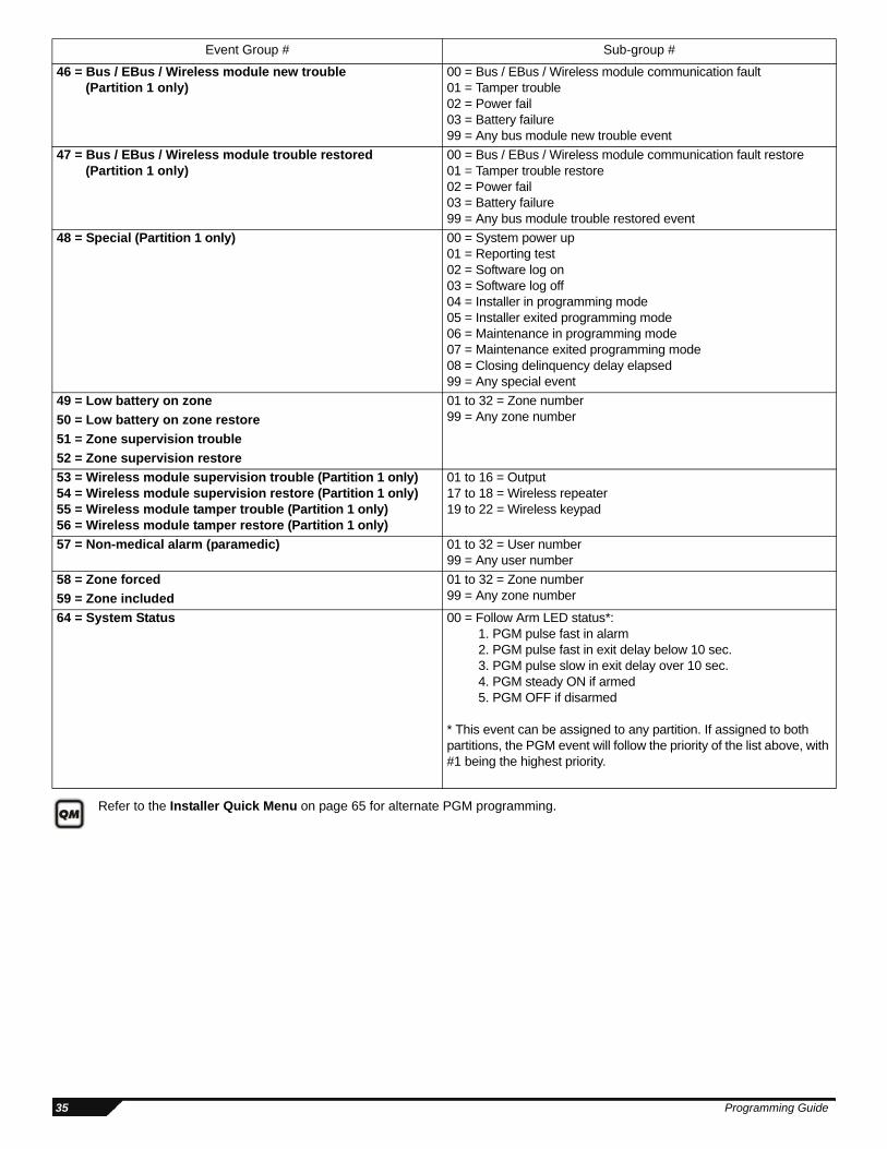
Refer to the Installer Quick Menu on page 65 for alternate PGM programming.
46 = Bus / EBus / Wireless module new trouble (Partition 1 only)
00 = Bus / EBus / Wireless module communication fault 01 = Tamper trouble 02 = Power fail 03 = Battery failure 99 = Any bus module new trouble event
47 = Bus / EBus / Wireless module trouble restored (Partition 1 only)
00 = Bus / EBus / Wireless module communication fault restore 01 = Tamper trouble restore 02 = Power fail 03 = Battery failure 99 = Any bus module trouble restored event
48 = Special (Partition 1 only) 00 = System power up01 = Reporting test02 = Software log on03 = Software log off04 = Installer in programming mode05 = Installer exited programming mode06 = Maintenance in programming mode07 = Maintenance exited programming mode08 = Closing delinquency delay elapsed99 = Any special event
49 = Low battery on zone 01 to 32 = Zone number99 = Any zone number50 = Low battery on zone restore
51 = Zone supervision trouble52 = Zone supervision restore53 = Wireless module supervision trouble (Partition 1 only)54 = Wireless module supervision restore (Partition 1 only)55 = Wireless module tamper trouble (Partition 1 only)56 = Wireless module tamper restore (Partition 1 only)
01 to 16 = Output17 to 18 = Wireless repeater19 to 22 = Wireless keypad
57 = Non-medical alarm (paramedic) 01 to 32 = User number99 = Any user number
58 = Zone forced 01 to 32 = Zone number99 = Any zone number59 = Zone included
64 = System Status 00 = Follow Arm LED status*: 1. PGM pulse fast in alarm 2. PGM pulse fast in exit delay below 10 sec. 3. PGM pulse slow in exit delay over 10 sec. 4. PGM steady ON if armed 5. PGM OFF if disarmed
* This event can be assigned to any partition. If assigned to both partitions, the PGM event will follow the priority of the list above, with #1 being the highest priority.
Event Group # Sub-group #
35 Programming Guide
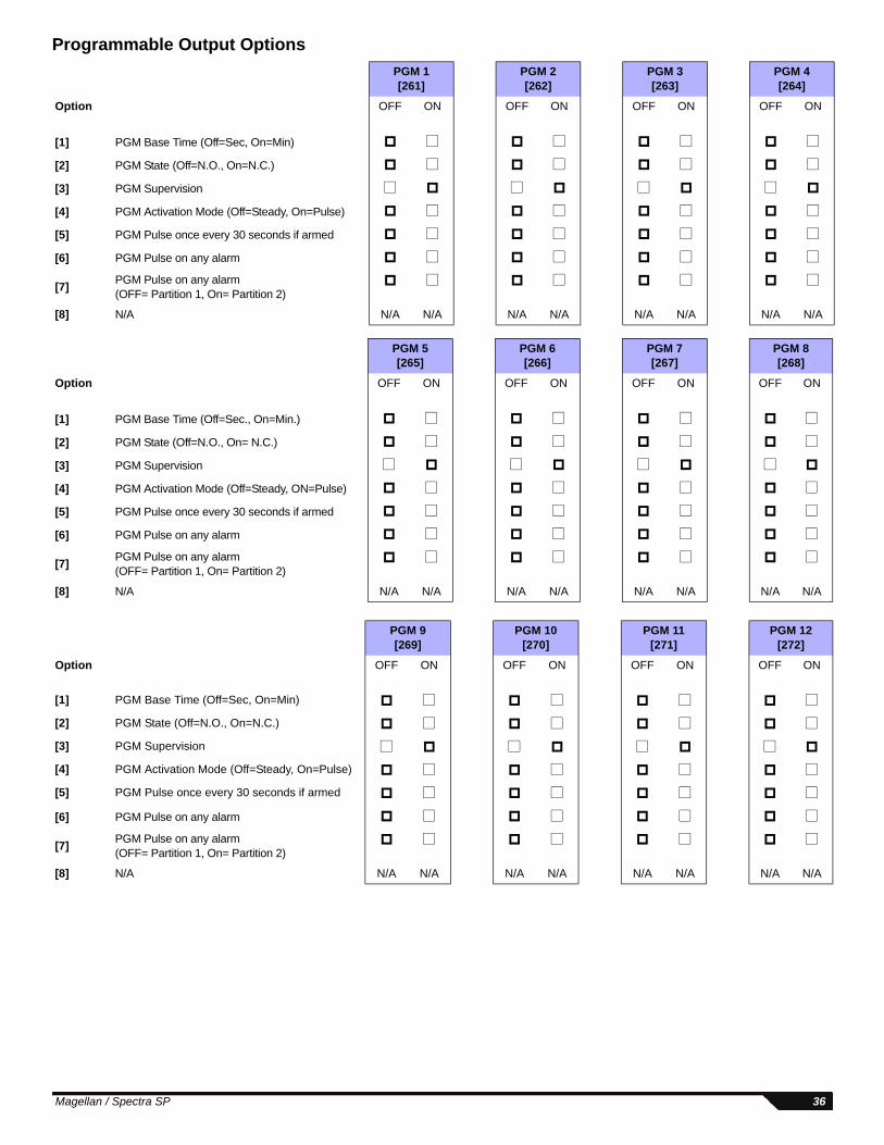
Programmable Output OptionsPGM 1[261]
PGM 2[262]
PGM 3[263]
PGM 4[264]
Option OFF ON OFF ON
OFF ON OFF ON
[1] PGM Base Time (Off=Sec, On=Min)
[2] PGM State (Off=N.O., On=N.C.)
[3] PGM Supervision
[4] PGM Activation Mode (Off=Steady, On=Pulse)
[5] PGM Pulse once every 30 seconds if armed
[6] PGM Pulse on any alarm
[7] PGM Pulse on any alarm (OFF= Partition 1, On= Partition 2)
[8] N/A N/A N/A N/A N/A N/A N/A N/A N/A
PGM 5[265]
PGM 6[266]
PGM 7[267]
PGM 8[268]
Option OFF ON
OFF ON OFF ON OFF ON
[1] PGM Base Time (Off=Sec., On=Min.)
[2] PGM State (Off=N.O., On= N.C.)
[3] PGM Supervision
[4] PGM Activation Mode (Off=Steady, ON=Pulse)
[5] PGM Pulse once every 30 seconds if armed
[6] PGM Pulse on any alarm
[7] PGM Pulse on any alarm (OFF= Partition 1, On= Partition 2)
[8] N/A N/A N/A N/A N/A N/A N/A N/A N/A
PGM 9[269]
PGM 10[270]
PGM 11[271]
PGM 12[272]
Option OFF ON
OFF ON OFF ON OFF ON
[1] PGM Base Time (Off=Sec, On=Min)
[2] PGM State (Off=N.O., On=N.C.)
[3] PGM Supervision
[4] PGM Activation Mode (Off=Steady, On=Pulse)
[5] PGM Pulse once every 30 seconds if armed
[6] PGM Pulse on any alarm
[7] PGM Pulse on any alarm (OFF= Partition 1, On= Partition 2)
[8] N/A N/A N/A N/A N/A N/A N/A N/A N/A
Magellan / Spectra SP 36
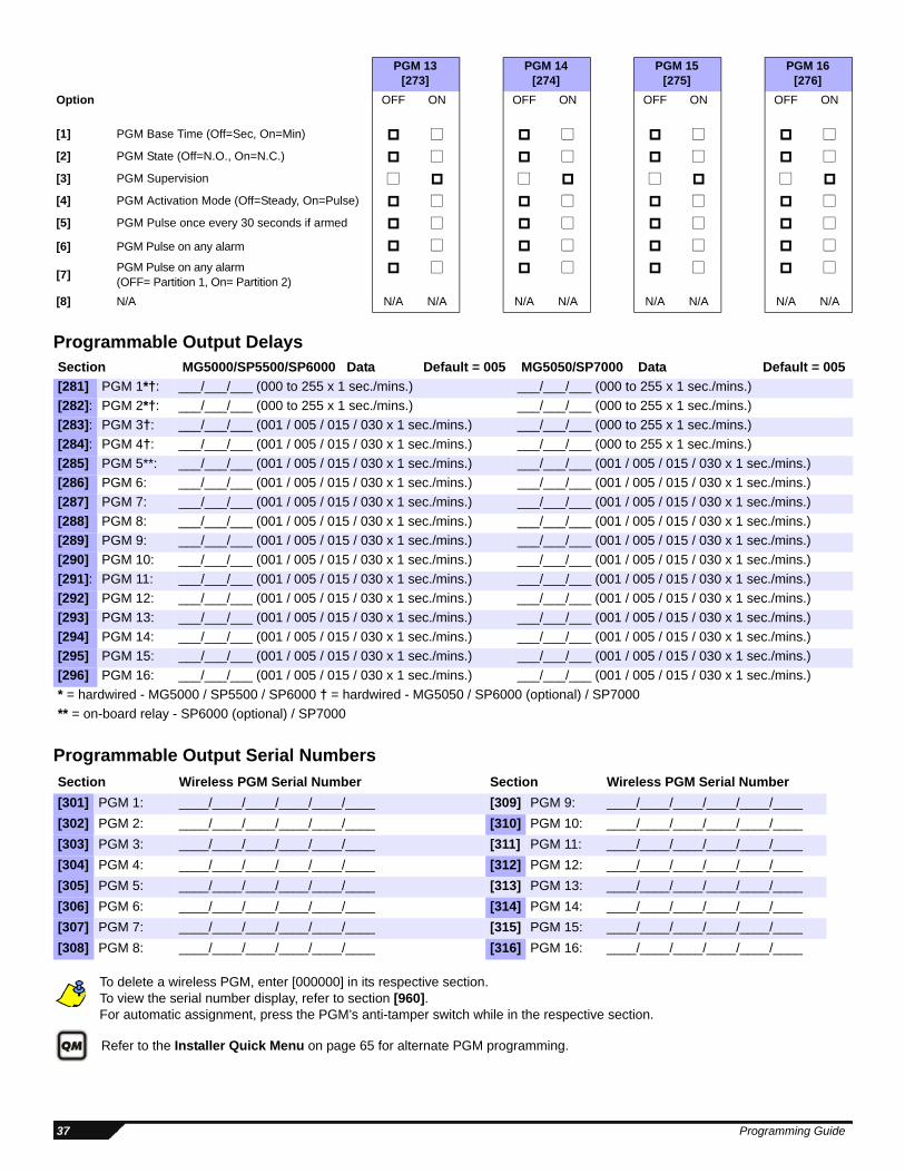
Programmable Output Delays
Programmable Output Serial Numbers
To delete a wireless PGM, enter [000000] in its respective section. To view the serial number display, refer to section [960].For automatic assignment, press the PGM’s anti-tamper switch while in the respective section.
Refer to the Installer Quick Menu on page 65 for alternate PGM programming.
PGM 13[273]
PGM 14[274]
PGM 15[275]
PGM 16[276]
Option OFF ON OFF ON OFF ON OFF ON
[1] PGM Base Time (Off=Sec, On=Min) [2] PGM State (Off=N.O., On=N.C.) [3] PGM Supervision [4] PGM Activation Mode (Off=Steady, On=Pulse) [5] PGM Pulse once every 30 seconds if armed
[6] PGM Pulse on any alarm
[7] PGM Pulse on any alarm (OFF= Partition 1, On= Partition 2)
[8] N/A N/A N/A N/A N/A N/A N/A N/A N/A
Section MG5000/SP5500/SP6000 Data Default = 005 MG5050/SP7000 Data Default = 005[281] PGM 1*†: ___/___/___ (000 to 255 x 1 sec./mins.) ___/___/___ (000 to 255 x 1 sec./mins.)[282]: PGM 2*†: ___/___/___ (000 to 255 x 1 sec./mins.) ___/___/___ (000 to 255 x 1 sec./mins.)[283]: PGM 3†: ___/___/___ (001 / 005 / 015 / 030 x 1 sec./mins.) ___/___/___ (000 to 255 x 1 sec./mins.)[284]: PGM 4†: ___/___/___ (001 / 005 / 015 / 030 x 1 sec./mins.) ___/___/___ (000 to 255 x 1 sec./mins.)[285] PGM 5**: ___/___/___ (001 / 005 / 015 / 030 x 1 sec./mins.) ___/___/___ (001 / 005 / 015 / 030 x 1 sec./mins.)[286] PGM 6: ___/___/___ (001 / 005 / 015 / 030 x 1 sec./mins.) ___/___/___ (001 / 005 / 015 / 030 x 1 sec./mins.)[287] PGM 7: ___/___/___ (001 / 005 / 015 / 030 x 1 sec./mins.) ___/___/___ (001 / 005 / 015 / 030 x 1 sec./mins.)[288] PGM 8: ___/___/___ (001 / 005 / 015 / 030 x 1 sec./mins.) ___/___/___ (001 / 005 / 015 / 030 x 1 sec./mins.)[289] PGM 9: ___/___/___ (001 / 005 / 015 / 030 x 1 sec./mins.) ___/___/___ (001 / 005 / 015 / 030 x 1 sec./mins.)[290] PGM 10: ___/___/___ (001 / 005 / 015 / 030 x 1 sec./mins.) ___/___/___ (001 / 005 / 015 / 030 x 1 sec./mins.)[291]: PGM 11: ___/___/___ (001 / 005 / 015 / 030 x 1 sec./mins.) ___/___/___ (001 / 005 / 015 / 030 x 1 sec./mins.)[292] PGM 12: ___/___/___ (001 / 005 / 015 / 030 x 1 sec./mins.) ___/___/___ (001 / 005 / 015 / 030 x 1 sec./mins.)[293] PGM 13: ___/___/___ (001 / 005 / 015 / 030 x 1 sec./mins.) ___/___/___ (001 / 005 / 015 / 030 x 1 sec./mins.)[294] PGM 14: ___/___/___ (001 / 005 / 015 / 030 x 1 sec./mins.) ___/___/___ (001 / 005 / 015 / 030 x 1 sec./mins.)[295] PGM 15: ___/___/___ (001 / 005 / 015 / 030 x 1 sec./mins.) ___/___/___ (001 / 005 / 015 / 030 x 1 sec./mins.)[296] PGM 16: ___/___/___ (001 / 005 / 015 / 030 x 1 sec./mins.) ___/___/___ (001 / 005 / 015 / 030 x 1 sec./mins.)* = hardwired - MG5000 / SP5500 / SP6000 † = hardwired - MG5050 / SP6000 (optional) / SP7000** = on-board relay - SP6000 (optional) / SP7000
Section Wireless PGM Serial Number Section Wireless PGM Serial Number[301] PGM 1: ____/____/____/____/____/____ [309] PGM 9: ____/____/____/____/____/____[302] PGM 2: ____/____/____/____/____/____ [310] PGM 10: ____/____/____/____/____/____[303] PGM 3: ____/____/____/____/____/____ [311] PGM 11: ____/____/____/____/____/____[304] PGM 4: ____/____/____/____/____/____ [312] PGM 12: ____/____/____/____/____/____[305] PGM 5: ____/____/____/____/____/____ [313] PGM 13: ____/____/____/____/____/____[306] PGM 6: ____/____/____/____/____/____ [314] PGM 14: ____/____/____/____/____/____[307] PGM 7: ____/____/____/____/____/____ [315] PGM 15: ____/____/____/____/____/____[308] PGM 8: ____/____/____/____/____/____ [316] PGM 16: ____/____/____/____/____/____
37 Programming Guide
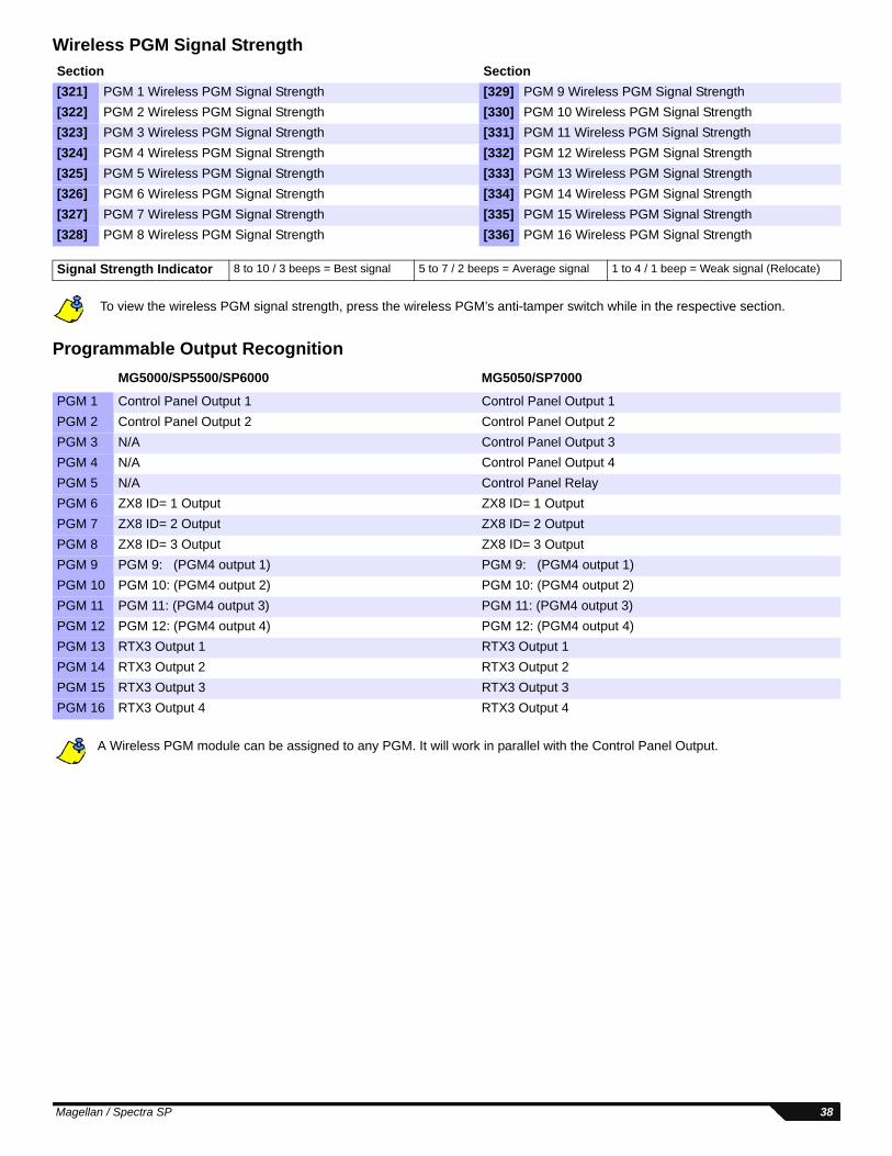
Wireless PGM Signal Strength
To view the wireless PGM signal strength, press the wireless PGM’s anti-tamper switch while in the respective section.
Programmable Output Recognition
A Wireless PGM module can be assigned to any PGM. It will work in parallel with the Control Panel Output.
Section Section[321] PGM 1 Wireless PGM Signal Strength [329] PGM 9 Wireless PGM Signal Strength[322] PGM 2 Wireless PGM Signal Strength [330] PGM 10 Wireless PGM Signal Strength[323] PGM 3 Wireless PGM Signal Strength [331] PGM 11 Wireless PGM Signal Strength[324] PGM 4 Wireless PGM Signal Strength [332] PGM 12 Wireless PGM Signal Strength[325] PGM 5 Wireless PGM Signal Strength [333] PGM 13 Wireless PGM Signal Strength[326] PGM 6 Wireless PGM Signal Strength [334] PGM 14 Wireless PGM Signal Strength[327] PGM 7 Wireless PGM Signal Strength [335] PGM 15 Wireless PGM Signal Strength[328] PGM 8 Wireless PGM Signal Strength [336] PGM 16 Wireless PGM Signal Strength
Signal Strength Indicator 8 to 10 / 3 beeps = Best signal 5 to 7 / 2 beeps = Average signal 1 to 4 / 1 beep = Weak signal (Relocate)
MG5000/SP5500/SP6000 MG5050/SP7000
PGM 1 Control Panel Output 1 Control Panel Output 1PGM 2 Control Panel Output 2 Control Panel Output 2PGM 3 N/A Control Panel Output 3PGM 4 N/A Control Panel Output 4PGM 5 N/A Control Panel RelayPGM 6 ZX8 ID= 1 Output ZX8 ID= 1 OutputPGM 7 ZX8 ID= 2 Output ZX8 ID= 2 OutputPGM 8 ZX8 ID= 3 Output ZX8 ID= 3 OutputPGM 9 PGM 9: (PGM4 output 1) PGM 9: (PGM4 output 1)PGM 10 PGM 10: (PGM4 output 2) PGM 10: (PGM4 output 2)PGM 11 PGM 11: (PGM4 output 3) PGM 11: (PGM4 output 3)PGM 12 PGM 12: (PGM4 output 4) PGM 12: (PGM4 output 4)PGM 13 RTX3 Output 1 RTX3 Output 1PGM 14 RTX3 Output 2 RTX3 Output 2PGM 15 RTX3 Output 3 RTX3 Output 3PGM 16 RTX3 Output 4 RTX3 Output 4
Magellan / Spectra SP 38
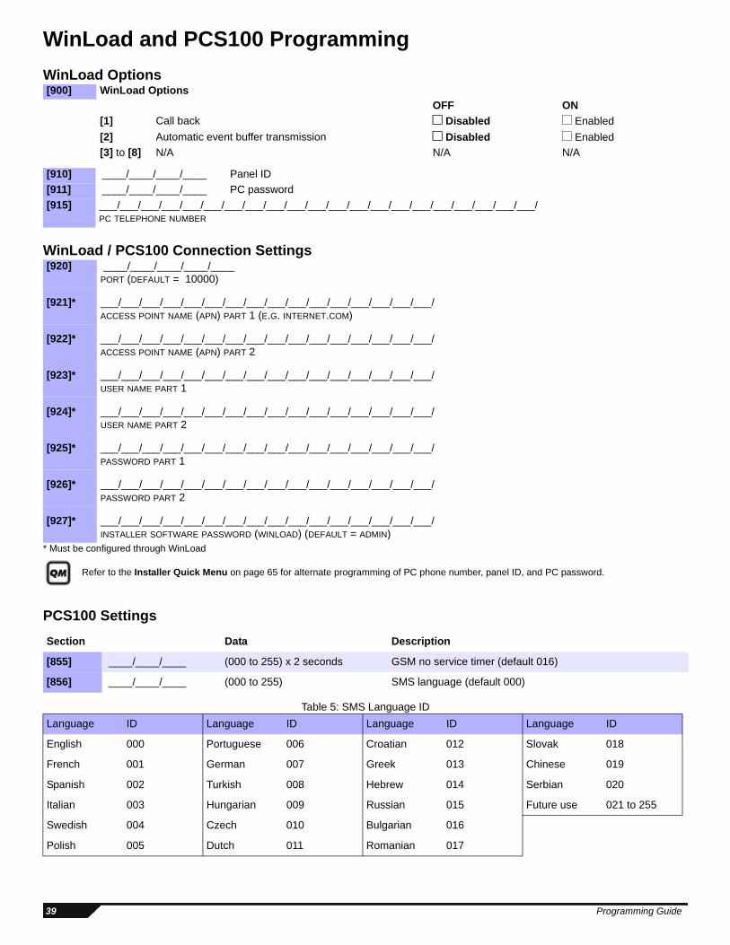
WinLoad and PCS100 ProgrammingWinLoad Options
WinLoad / PCS100 Connection Settings
* Must be configured through WinLoad
Refer to the Installer Quick Menu on page 65 for alternate programming of PC phone number, panel ID, and PC password.
PCS100 Settings
Table 5: SMS Language ID
[900] WinLoad OptionsOFF ON
[1] Call back Disabled Enabled[2] Automatic event buffer transmission Disabled Enabled[3] to [8] N/A N/A N/A
[910] ____/____/____/____ Panel ID[911] ____/____/____/____ PC password[915] ___/___/___/___/___/___/___/___/___/___/___/___/___/___/___/___/___/___/___/___/___/
PC TELEPHONE NUMBER
[920] ____/____/____/____/____PORT (DEFAULT = 10000)
[921]* ___/___/___/___/___/___/___/___/___/___/___/___/___/___/___/___/ACCESS POINT NAME (APN) PART 1 (E.G. INTERNET.COM)
[922]* ___/___/___/___/___/___/___/___/___/___/___/___/___/___/___/___/ACCESS POINT NAME (APN) PART 2
[923]* ___/___/___/___/___/___/___/___/___/___/___/___/___/___/___/___/USER NAME PART 1
[924]* ___/___/___/___/___/___/___/___/___/___/___/___/___/___/___/___/USER NAME PART 2
[925]* ___/___/___/___/___/___/___/___/___/___/___/___/___/___/___/___/PASSWORD PART 1
[926]* ___/___/___/___/___/___/___/___/___/___/___/___/___/___/___/___/PASSWORD PART 2
[927]* ___/___/___/___/___/___/___/___/___/___/___/___/___/___/___/___/INSTALLER SOFTWARE PASSWORD (WINLOAD) (DEFAULT = ADMIN)
Section Data Description
[855] ____/____/____ (000 to 255) x 2 seconds GSM no service timer (default 016)
[856] ____/____/____ (000 to 255) SMS language (default 000)
Language ID Language ID Language ID Language ID
English 000 Portuguese 006 Croatian 012 Slovak 018
French 001 German 007 Greek 013 Chinese 019
Spanish 002 Turkish 008 Hebrew 014 Serbian 020
Italian 003 Hungarian 009 Russian 015 Future use 021 to 255
Swedish 004 Czech 010 Bulgarian 016
Polish 005 Dutch 011 Romanian 017
39 Programming Guide
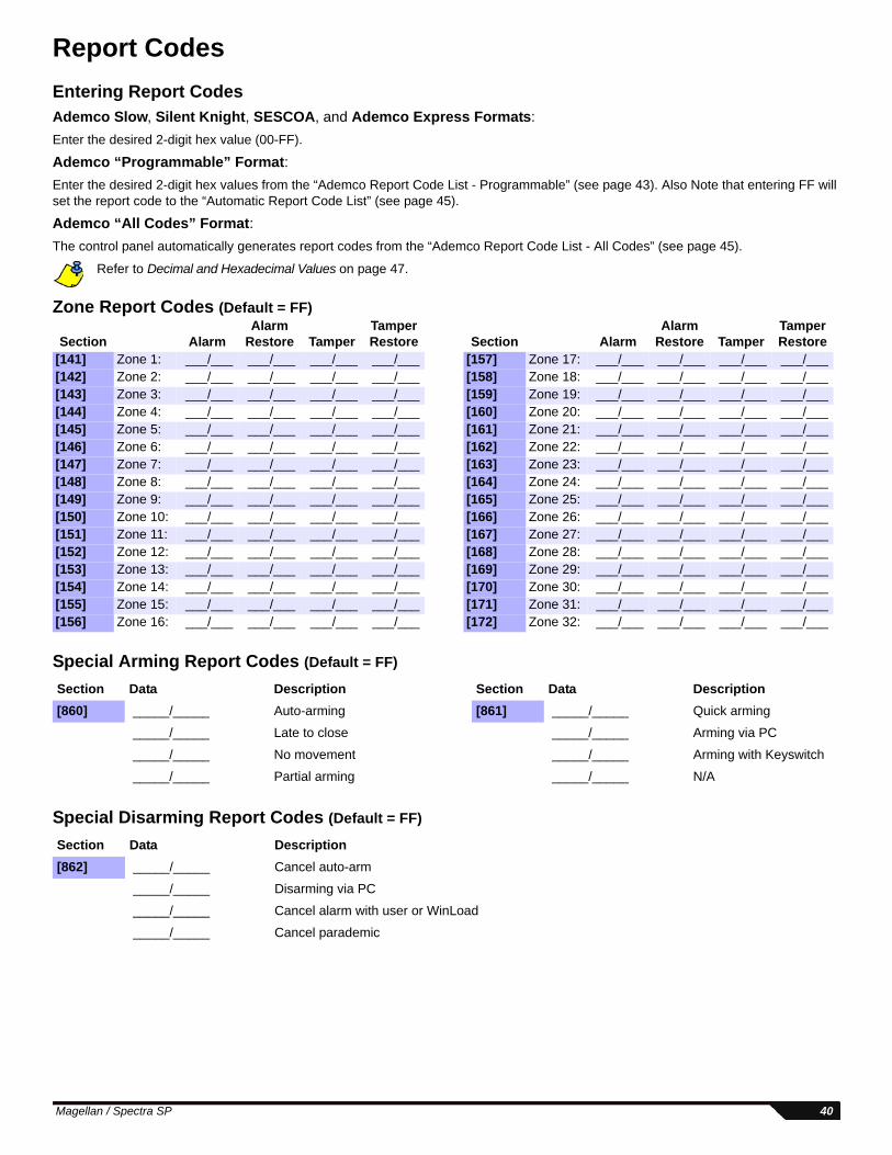
Report CodesEntering Report CodesAdemco Slow, Silent Knight, SESCOA, and Ademco Express Formats: Enter the desired 2-digit hex value (00-FF).
Ademco “Programmable” Format: Enter the desired 2-digit hex values from the “Ademco Report Code List - Programmable” (see page 43). Also Note that entering FF will set the report code to the “Automatic Report Code List” (see page 45).
Ademco “All Codes” Format: The control panel automatically generates report codes from the “Ademco Report Code List - All Codes” (see page 45).
Refer to Decimal and Hexadecimal Values on page 47.
Zone Report Codes (Default = FF)
Special Arming Report Codes (Default = FF)
Special Disarming Report Codes (Default = FF)
Section AlarmAlarm
Restore TamperTamper Restore Section Alarm
Alarm Restore Tamper
Tamper Restore
[141] Zone 1: ___/___ ___/___ ___/___ ___/___ [157] Zone 17: ___/___ ___/___ ___/___ ___/___[142] Zone 2: ___/___ ___/___ ___/___ ___/___ [158] Zone 18: ___/___ ___/___ ___/___ ___/___[143] Zone 3: ___/___ ___/___ ___/___ ___/___ [159] Zone 19: ___/___ ___/___ ___/___ ___/___[144] Zone 4: ___/___ ___/___ ___/___ ___/___ [160] Zone 20: ___/___ ___/___ ___/___ ___/___[145] Zone 5: ___/___ ___/___ ___/___ ___/___ [161] Zone 21: ___/___ ___/___ ___/___ ___/___[146] Zone 6: ___/___ ___/___ ___/___ ___/___ [162] Zone 22: ___/___ ___/___ ___/___ ___/___[147] Zone 7: ___/___ ___/___ ___/___ ___/___ [163] Zone 23: ___/___ ___/___ ___/___ ___/___[148] Zone 8: ___/___ ___/___ ___/___ ___/___ [164] Zone 24: ___/___ ___/___ ___/___ ___/___[149] Zone 9: ___/___ ___/___ ___/___ ___/___ [165] Zone 25: ___/___ ___/___ ___/___ ___/___[150] Zone 10: ___/___ ___/___ ___/___ ___/___ [166] Zone 26: ___/___ ___/___ ___/___ ___/___[151] Zone 11: ___/___ ___/___ ___/___ ___/___ [167] Zone 27: ___/___ ___/___ ___/___ ___/___[152] Zone 12: ___/___ ___/___ ___/___ ___/___ [168] Zone 28: ___/___ ___/___ ___/___ ___/___[153] Zone 13: ___/___ ___/___ ___/___ ___/___ [169] Zone 29: ___/___ ___/___ ___/___ ___/___[154] Zone 14: ___/___ ___/___ ___/___ ___/___ [170] Zone 30: ___/___ ___/___ ___/___ ___/___[155] Zone 15: ___/___ ___/___ ___/___ ___/___ [171] Zone 31: ___/___ ___/___ ___/___ ___/___[156] Zone 16: ___/___ ___/___ ___/___ ___/___ [172] Zone 32: ___/___ ___/___ ___/___ ___/___
Section Data Description Section Data Description[860] _____/_____ Auto-arming [861] _____/_____ Quick arming
_____/_____ Late to close _____/_____ Arming via PC
_____/_____ No movement _____/_____ Arming with Keyswitch
_____/_____ Partial arming _____/_____ N/A
Section Data Description[862] _____/_____ Cancel auto-arm
_____/_____ Disarming via PC
_____/_____ Cancel alarm with user or WinLoad
_____/_____ Cancel parademic
Magellan / Spectra SP 40
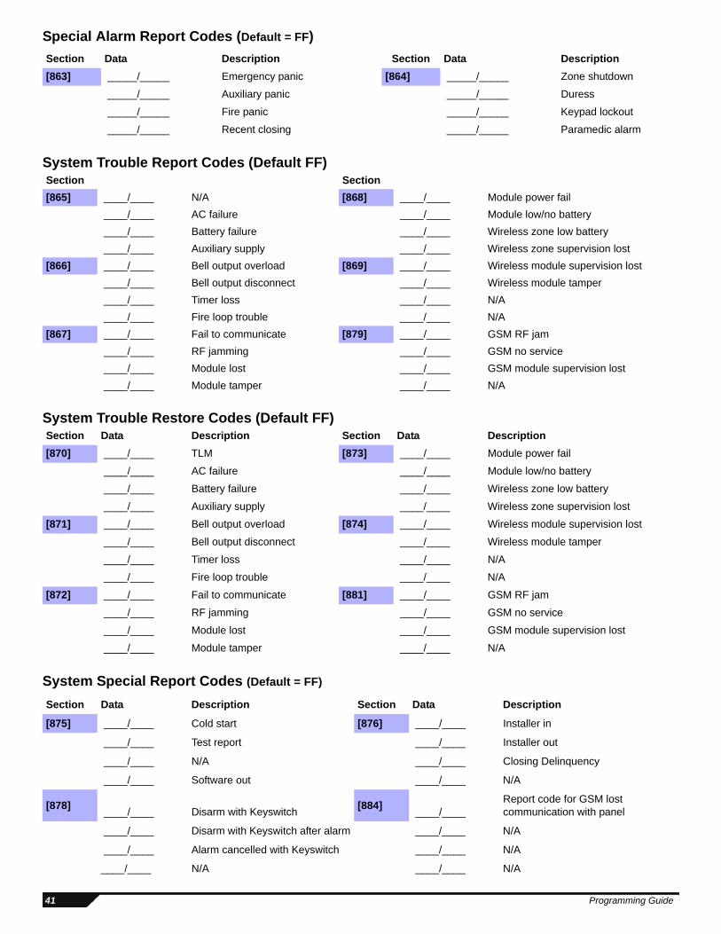
Special Alarm Report Codes (Default = FF)
System Trouble Report Codes (Default FF)
System Trouble Restore Codes (Default FF)
System Special Report Codes (Default = FF)
Section Data Description Section Data Description[863] _____/_____ Emergency panic [864] _____/_____ Zone shutdown
_____/_____ Auxiliary panic _____/_____ Duress
_____/_____ Fire panic _____/_____ Keypad lockout
_____/_____ Recent closing _____/_____ Paramedic alarm
Section Section[865] ____/____ N/A [868] ____/____ Module power fail
____/____ AC failure ____/____ Module low/no battery ____/____ Battery failure ____/____ Wireless zone low battery ____/____ Auxiliary supply ____/____ Wireless zone supervision lost
[866] ____/____ Bell output overload [869] ____/____ Wireless module supervision lost ____/____ Bell output disconnect ____/____ Wireless module tamper ____/____ Timer loss ____/____ N/A ____/____ Fire loop trouble ____/____ N/A
[867] ____/____ Fail to communicate [879] ____/____ GSM RF jam ____/____ RF jamming ____/____ GSM no service ____/____ Module lost ____/____ GSM module supervision lost ____/____ Module tamper ____/____ N/A
Section Data Description Section Data Description[870] ____/____ TLM [873] ____/____ Module power fail
____/____ AC failure ____/____ Module low/no battery
____/____ Battery failure ____/____ Wireless zone low battery
____/____ Auxiliary supply ____/____ Wireless zone supervision lost
[871] ____/____ Bell output overload [874] ____/____ Wireless module supervision lost
____/____ Bell output disconnect ____/____ Wireless module tamper
____/____ Timer loss ____/____ N/A
____/____ Fire loop trouble ____/____ N/A
[872] ____/____ Fail to communicate [881] ____/____ GSM RF jam
____/____ RF jamming ____/____ GSM no service
____/____ Module lost ____/____ GSM module supervision lost
____/____ Module tamper ____/____ N/A
Section Data Description Section Data Description
[875] ____/____ Cold start [876] ____/____ Installer in
____/____ Test report ____/____ Installer out
____/____ N/A ____/____ Closing Delinquency
____/____ Software out ____/____ N/A
[878] ____/____ Disarm with Keyswitch [884] ____/____Report code for GSM lost communication with panel
____/____ Disarm with Keyswitch after alarm ____/____ N/A
____/____ Alarm cancelled with Keyswitch ____/____ N/A
____/____ N/A ____/____ N/A
41 Programming Guide
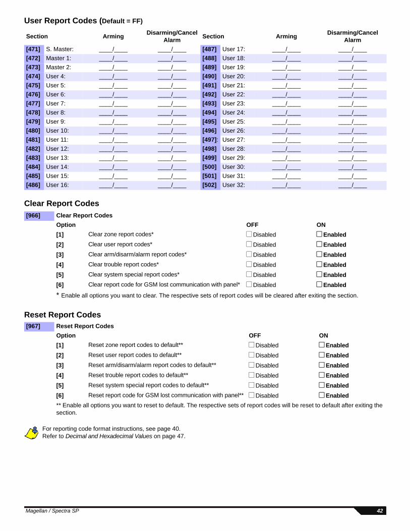
User Report Codes (Default = FF)
Clear Report Codes
Reset Report Codes
For reporting code format instructions, see page 40.Refer to Decimal and Hexadecimal Values on page 47.
Section Arming Disarming/Cancel Alarm Section Arming Disarming/Cancel
Alarm[471] S. Master: ____/____ ____/____ [487] User 17: ____/____ ____/____[472] Master 1: ____/____ ____/____ [488] User 18: ____/____ ____/____[473] Master 2: ____/____ ____/____ [489] User 19: ____/____ ____/____[474] User 4: ____/____ ____/____ [490] User 20: ____/____ ____/____[475] User 5: ____/____ ____/____ [491] User 21: ____/____ ____/____[476] User 6: ____/____ ____/____ [492] User 22: ____/____ ____/____[477] User 7: ____/____ ____/____ [493] User 23: ____/____ ____/____[478] User 8: ____/____ ____/____ [494] User 24: ____/____ ____/____[479] User 9: ____/____ ____/____ [495] User 25: ____/____ ____/____[480] User 10: ____/____ ____/____ [496] User 26: ____/____ ____/____[481] User 11: ____/____ ____/____ [497]: User 27: ____/____ ____/____[482] User 12: ____/____ ____/____ [498] User 28: ____/____ ____/____[483] User 13: ____/____ ____/____ [499] User 29: ____/____ ____/____[484] User 14: ____/____ ____/____ [500] User 30: ____/____ ____/____[485] User 15: ____/____ ____/____ [501] User 31: ____/____ ____/____[486] User 16: ____/____ ____/____ [502] User 32: ____/____ ____/____
[966] Clear Report CodesOption OFF ON[1] Clear zone report codes* Disabled Enabled[2] Clear user report codes* Disabled Enabled[3] Clear arm/disarm/alarm report codes* Disabled Enabled[4] Clear trouble report codes* Disabled Enabled[5] Clear system special report codes* Disabled Enabled[6] Clear report code for GSM lost communication with panel* Disabled Enabled
* Enable all options you want to clear. The respective sets of report codes will be cleared after exiting the section.
[967] Reset Report CodesOption OFF ON[1] Reset zone report codes to default** Disabled Enabled[2] Reset user report codes to default** Disabled Enabled[3] Reset arm/disarm/alarm report codes to default** Disabled Enabled[4] Reset trouble report codes to default** Disabled Enabled[5] Reset system special report codes to default** Disabled Enabled[6] Reset report code for GSM lost communication with panel** Disabled Enabled** Enable all options you want to reset to default. The respective sets of report codes will be reset to default after exiting the section.
Magellan / Spectra SP 42
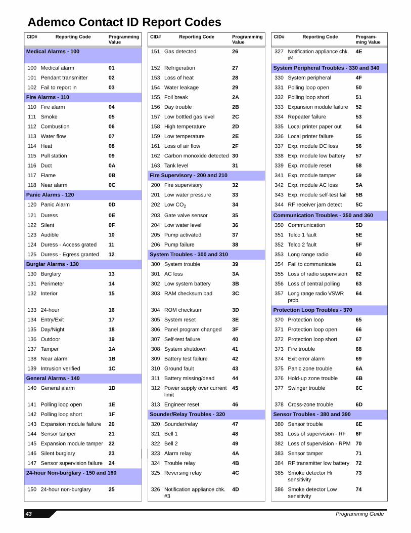
Ademco Contact ID Report CodesCID# Reporting Code Programming
ValueCID# Reporting Code Programming
ValueCID# Reporting Code Program-
ming Value
Medical Alarms - 100 151 Gas detected 26 327 Notification appliance chk. #4
4E
100 Medical alarm 01 152 Refrigeration 27 System Peripheral Troubles - 330 and 340
101 Pendant transmitter 02 153 Loss of heat 28 330 System peripheral 4F
102 Fail to report in 03 154 Water leakage 29 331 Polling loop open 50
Fire Alarms - 110 155 Foil break 2A 332 Polling loop short 51
110 Fire alarm 04 156 Day trouble 2B 333 Expansion module failure 52
111 Smoke 05 157 Low bottled gas level 2C 334 Repeater failure 53
112 Combustion 06 158 High temperature 2D 335 Local printer paper out 54
113 Water flow 07 159 Low temperature 2E 336 Local printer failure 55
114 Heat 08 161 Loss of air flow 2F 337 Exp. module DC loss 56
115 Pull station 09 162 Carbon monoxide detected 30 338 Exp. module low battery 57
116 Duct 0A 163 Tank level 31 339 Exp. module reset 58
117 Flame 0B Fire Supervisory - 200 and 210 341 Exp. module tamper 59
118 Near alarm 0C 200 Fire supervisory 32 342 Exp. module AC loss 5A
Panic Alarms - 120 201 Low water pressure 33 343 Exp. module self-test fail 5B
120 Panic Alarm 0D 202 Low CO2 34 344 RF receiver jam detect 5C
121 Duress 0E 203 Gate valve sensor 35 Communication Troubles - 350 and 360
122 Silent 0F 204 Low water level 36 350 Communication 5D
123 Audible 10 205 Pump activated 37 351 Telco 1 fault 5E
124 Duress - Access grated 11 206 Pump failure 38 352 Telco 2 fault 5F
125 Duress - Egress granted 12 System Troubles - 300 and 310 353 Long range radio 60
Burglar Alarms - 130 300 System trouble 39 354 Fail to communicate 61
130 Burglary 13 301 AC loss 3A 355 Loss of radio supervision 62
131 Perimeter 14 302 Low system battery 3B 356 Loss of central polling 63
132 Interior 15 303 RAM checksum bad 3C 357 Long range radio VSWR prob.
64
133 24-hour 16 304 ROM checksum 3D Protection Loop Troubles - 370
134 Entry/Exit 17 305 System reset 3E 370 Protection loop 65
135 Day/Night 18 306 Panel program changed 3F 371 Protection loop open 66
136 Outdoor 19 307 Self-test failure 40 372 Protection loop short 67
137 Tamper 1A 308 System shutdown 41 373 Fire trouble 68
138 Near alarm 1B 309 Battery test failure 42 374 Exit error alarm 69
139 Intrusion verified 1C 310 Ground fault 43 375 Panic zone trouble 6A
General Alarms - 140 311 Battery missing/dead 44 376 Hold-up zone trouble 6B
140 General alarm 1D 312 Power supply over current limit
45 377 Swinger trouble 6C
141 Polling loop open 1E 313 Engineer reset 46 378 Cross-zone trouble 6D
142 Polling loop short 1F Sounder/Relay Troubles - 320 Sensor Troubles - 380 and 390
143 Expansion module failure 20 320 Sounder/relay 47 380 Sensor trouble 6E
144 Sensor tamper 21 321 Bell 1 48 381 Loss of supervision - RF 6F
145 Expansion module tamper 22 322 Bell 2 49 382 Loss of supervision - RPM 70
146 Silent burglary 23 323 Alarm relay 4A 383 Sensor tamper 71
147 Sensor supervision failure 24 324 Trouble relay 4B 384 RF transmitter low battery 72
24-hour Non-burglary - 150 and 160 325 Reversing relay 4C 385 Smoke detector Hi sensitivity
73
150 24-hour non-burglary 25 326 Notification appliance chk. #3
4D 386 Smoke detector Low sensitivity
74
43 Programming Guide
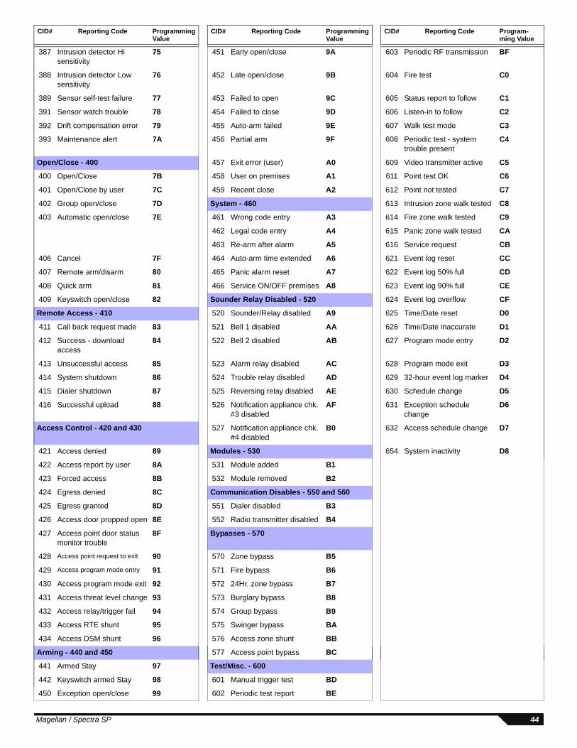
387 Intrusion detector Hi sensitivity
75 451 Early open/close 9A 603 Periodic RF transmission BF
388 Intrusion detector Low sensitivity
76 452 Late open/close 9B 604 Fire test C0
389 Sensor self-test failure 77 453 Failed to open 9C 605 Status report to follow C1
391 Sensor watch trouble 78 454 Failed to close 9D 606 Listen-in to follow C2
392 Drift compensation error 79 455 Auto-arm failed 9E 607 Walk test mode C3
393 Maintenance alert 7A 456 Partial arm 9F 608 Periodic test - system trouble present
C4
Open/Close - 400 457 Exit error (user) A0 609 Video transmitter active C5
400 Open/Close 7B 458 User on premises A1 611 Point test OK C6
401 Open/Close by user 7C 459 Recent close A2 612 Point not tested C7
402 Group open/close 7D System - 460 613 Intrusion zone walk tested C8
403 Automatic open/close 7E 461 Wrong code entry A3 614 Fire zone walk tested C9
462 Legal code entry A4 615 Panic zone walk tested CA
463 Re-arm after alarm A5 616 Service request CB
406 Cancel 7F 464 Auto-arm time extended A6 621 Event log reset CC
407 Remote arm/disarm 80 465 Panic alarm reset A7 622 Event log 50% full CD
408 Quick arm 81 466 Service ON/OFF premises A8 623 Event log 90% full CE
409 Keyswitch open/close 82 Sounder Relay Disabled - 520 624 Event log overflow CF
Remote Access - 410 520 Sounder/Relay disabled A9 625 Time/Date reset D0
411 Call back request made 83 521 Bell 1 disabled AA 626 Time/Date inaccurate D1
412 Success - download access
84 522 Bell 2 disabled AB 627 Program mode entry D2
413 Unsuccessful access 85 523 Alarm relay disabled AC 628 Program mode exit D3
414 System shutdown 86 524 Trouble relay disabled AD 629 32-hour event log marker D4
415 Dialer shutdown 87 525 Reversing relay disabled AE 630 Schedule change D5
416 Successful upload 88 526 Notification appliance chk. #3 disabled
AF 631 Exception schedule change
D6
Access Control - 420 and 430 527 Notification appliance chk. #4 disabled
B0 632 Access schedule change D7
421 Access denied 89 Modules - 530 654 System inactivity D8
422 Access report by user 8A 531 Module added B1
423 Forced access 8B 532 Module removed B2
424 Egress denied 8C Communication Disables - 550 and 560
425 Egress granted 8D 551 Dialer disabled B3
426 Access door propped open 8E 552 Radio transmitter disabled B4
427 Access point door status monitor trouble
8F Bypasses - 570
428 Access point request to exit 90 570 Zone bypass B5
429 Access program mode entry 91 571 Fire bypass B6
430 Access program mode exit 92 572 24Hr. zone bypass B7
431 Access threat level change 93 573 Burglary bypass B8
432 Access relay/trigger fail 94 574 Group bypass B9
433 Access RTE shunt 95 575 Swinger bypass BA
434 Access DSM shunt 96 576 Access zone shunt BB
Arming - 440 and 450 577 Access point bypass BC
441 Armed Stay 97 Test/Misc. - 600
442 Keyswitch armed Stay 98 601 Manual trigger test BD
450 Exception open/close 99 602 Periodic test report BE
CID# Reporting Code Programming Value
CID# Reporting Code Programming Value
CID# Reporting Code Program-ming Value
Magellan / Spectra SP 44
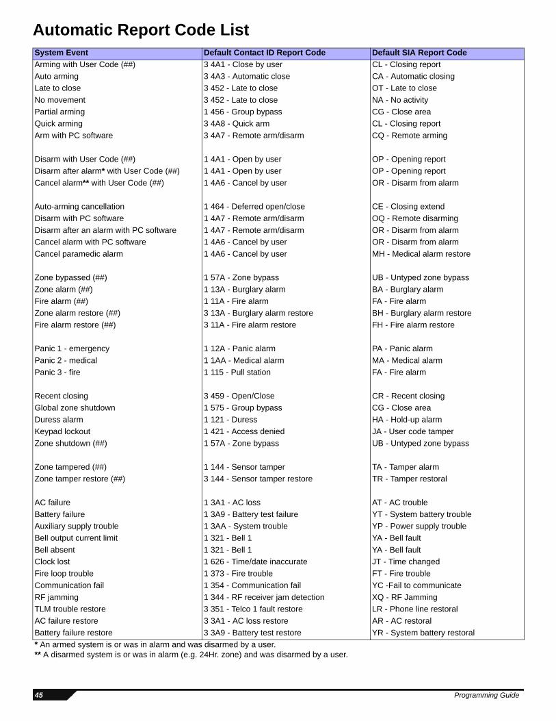
Automatic Report Code List System Event Default Contact ID Report Code Default SIA Report CodeArming with User Code (##) 3 4A1 - Close by user CL - Closing reportAuto arming 3 4A3 - Automatic close CA - Automatic closingLate to close 3 452 - Late to close OT - Late to closeNo movement 3 452 - Late to close NA - No activityPartial arming 1 456 - Group bypass CG - Close areaQuick arming 3 4A8 - Quick arm CL - Closing reportArm with PC software 3 4A7 - Remote arm/disarm CQ - Remote arming
Disarm with User Code (##) 1 4A1 - Open by user OP - Opening reportDisarm after alarm* with User Code (##) 1 4A1 - Open by user OP - Opening reportCancel alarm** with User Code (##) 1 4A6 - Cancel by user OR - Disarm from alarm
Auto-arming cancellation 1 464 - Deferred open/close CE - Closing extendDisarm with PC software 1 4A7 - Remote arm/disarm OQ - Remote disarmingDisarm after an alarm with PC software 1 4A7 - Remote arm/disarm OR - Disarm from alarmCancel alarm with PC software 1 4A6 - Cancel by user OR - Disarm from alarmCancel paramedic alarm 1 4A6 - Cancel by user MH - Medical alarm restore
Zone bypassed (##) 1 57A - Zone bypass UB - Untyped zone bypassZone alarm (##) 1 13A - Burglary alarm BA - Burglary alarmFire alarm (##) 1 11A - Fire alarm FA - Fire alarmZone alarm restore (##) 3 13A - Burglary alarm restore BH - Burglary alarm restoreFire alarm restore (##) 3 11A - Fire alarm restore FH - Fire alarm restore
Panic 1 - emergency 1 12A - Panic alarm PA - Panic alarmPanic 2 - medical 1 1AA - Medical alarm MA - Medical alarmPanic 3 - fire 1 115 - Pull station FA - Fire alarm
Recent closing 3 459 - Open/Close CR - Recent closingGlobal zone shutdown 1 575 - Group bypass CG - Close areaDuress alarm 1 121 - Duress HA - Hold-up alarmKeypad lockout 1 421 - Access denied JA - User code tamperZone shutdown (##) 1 57A - Zone bypass UB - Untyped zone bypass
Zone tampered (##) 1 144 - Sensor tamper TA - Tamper alarmZone tamper restore (##) 3 144 - Sensor tamper restore TR - Tamper restoral
AC failure 1 3A1 - AC loss AT - AC troubleBattery failure 1 3A9 - Battery test failure YT - System battery troubleAuxiliary supply trouble 1 3AA - System trouble YP - Power supply troubleBell output current limit 1 321 - Bell 1 YA - Bell faultBell absent 1 321 - Bell 1 YA - Bell faultClock lost 1 626 - Time/date inaccurate JT - Time changedFire loop trouble 1 373 - Fire trouble FT - Fire troubleCommunication fail 1 354 - Communication fail YC -Fail to communicateRF jamming 1 344 - RF receiver jam detection XQ - RF JammingTLM trouble restore 3 351 - Telco 1 fault restore LR - Phone line restoralAC failure restore 3 3A1 - AC loss restore AR - AC restoralBattery failure restore 3 3A9 - Battery test restore YR - System battery restoral* An armed system is or was in alarm and was disarmed by a user.** A disarmed system is or was in alarm (e.g. 24Hr. zone) and was disarmed by a user.
45 Programming Guide

Auxiliary supply trouble restore 3 3AA - System trouble restore YQ - Power supply restoredBell output current limit restore 3 321 - Bell 1 restore YH - Bell restoredBell absent restore 3 321 - Bell 1 restore YH - Bell restoredClock programmed 3 625 - Time/date reset JT - Time changedFire loop trouble restore 3 373 - Fire trouble restore FJ - Fire trouble restoreFail to communicate with monitoring station 3 354 - Fail to communicate YK - Communication failsRF jamming 3 344 - RF receiver jam detection XH - RF Jamming Restoral
Combus fault 1 333 - Expansion module failure ET - Expansion troubleModule tamper 1 341 - Expansion module tamper TA - Tamper alarm
Bus fault restore 3 333 - Expansion module failure restore ER - Expansion restoralModule tamper restore 3 341 - Expansion module tamper restore TR - Tamper restoral
Cold start 1 3A8 - System shutdown RR - Power upTest report engaged 1 6A2 - Periodic test report TX - Test reportPC software communication finished 1 412 - Successful - download access RS - Remote program successInstaller on site 1 627 - Program mode entry LB - Local programInstaller programming finished 1 628 - Program mode exit LS - Local program successMaintenance in 1 627 - Program mode entry LB - Local programMaintenance out 1 628 - Program mode exit LS - Local program successClosing delinquency 1 654 - System inactivity CD - System inactivityModule AC fail 1 342 - AC failure on module AT - Module AC failModule AC fail restore 3 342 - AC restored on module AR - Module AC fail restoreModule battery fail 1 338 - Battery failure on module YT - Module battery failModule battery fail restore 3 338 - Battery failure on module YR - Module battery fail restoreRF Module low battery 1 384 - RF transmitter low battery XT - Transmitter battery troubleRF Module battery restore 3 384 - RF transmitter battery restore XR - Transmitter battery restoralRF Module supervision trouble 1 381 - Loss of supervision - RF US - Untype zone supervisionRF Module supervision restore 3 381 - Supervision restore - RF UR - Untyped zone restoralRF Module supervision lost 1 381 - Loss of supervision- RF US - Untyped Zone SupervisoryRF Module supervision restore 3 381 - Loss of supervision- RF restore UR - Untyped Zone RestoralRF Module tamper 1 145 - Expansion module tamper ES - Expansion Device TamperRF Module tamper restore 3 145 - Expansion module tamper restore EJ - Expansion Device RestoreParamedic alarm 1 1AA - Medical MA - Medical AlarmZone forced 1 57A - Zone forced XW - Zone forcedZone included 3 57A - Zone included UU - Zone included
Keyswitch arm 34A9 - Keyswitch arm CS - Keyswitch armKeyswitch disarm 14A9 - Keyswitch disarm OS - Keyswitch disarmKeyswitch disarm after alarm 14A1 - Keyswitch disarm after alarm OS - Keyswitch disarm after alarmKeyswitch cancel alarm 14A6 - Keyswitch cancel alarm OS - Keyswitch cancel alarm
System Event Default Contact ID Report Code Default SIA Report Code
Magellan / Spectra SP 46
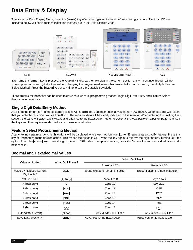
Data Entry & Display
There are two methods that can be used to enter data when in programming mode: Single Digit Data Entry and Feature Select Programming methods:
Single Digit Data Entry MethodAfter entering programming mode, some sections will require that you enter decimal values from 000 to 255. Other sections will require that you enter hexadecimal values from 0 to F. The required data will be clearly indicated in this manual. When entering the final digit in a section, the panel will automatically save and advance to the next section. Refer to Decimal and Hexadecimal Values on page 47 to see the keys and their equivalent decimal and/or hexadecimal value.
Feature Select Programming MethodAfter entering certain sections, eight options will be displayed where each option from [1] to [8] represents a specific feature. Press the key corresponding to the desired option. This means the option is ON. Press the key again to remove the digit, thereby, turning OFF the option. Press the [CLEAR] key to set all eight options to OFF. When the options are set, press the [ENTER] key to save and advance to the next section.
Decimal and Hexadecimal Values
Value or Action What Do I Press?What Do I See?
32-zone LED 10-zone LED
Value 0 / Replace Current Digit with 0
[SLEEP] Erase digit and remain in section Erase digit and remain in section
Values 1 to 9 [1] to [9] Zone 1 to 9 Keys 1 to 9
A (hex only) [0] Zone 10 Key 0(10)
B (hex only) [OFF] Zone 11 OFF
C (hex only) [BYP] Zone 12 BYP
D (hex only) [MEM] Zone 13 MEM
E (hex only) [TBL] Zone 14 TBL
F (hex only) [ ] Zone 15 [ ]
Exit Without Saving [CLEAR] ARM & STAY LED flash ARM & STAY LED flash
Save Data (hex only) [ENTER] Advances to the next section Advances to the next section
To access the Data Display Mode, press the [ENTER] key after entering a section and before entering any data. The four LEDs as indicated below will begin to flash indicating that you are in the Data Display Mode.
Each time the [ENTER] key is pressed, the keypad will display the next digit in the current section and will continue through all the following sections one digit at a time without changing the programmed values. Not available for sections using the Multiple Feature Select Method. Press the [CLEAR] key at any time to exit the Data Display Mode.
K636 K10V/H K32I/K32IRF/K32RF K32
47 Programming Guide
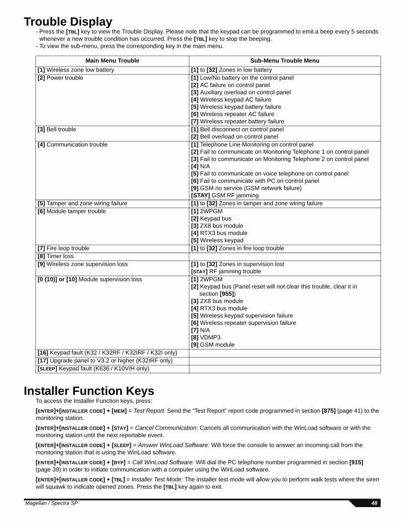
Trouble Display- Press the [TBL] key to view the Trouble Display. Please note that the keypad can be programmed to emit a beep every 5 seconds
whenever a new trouble condition has occurred. Press the [TBL] key to stop the beeping. - To view the sub-menu, press the corresponding key in the main menu.
Installer Function KeysTo access the Installer Function keys, press:
[ENTER]+[INSTALLER CODE] + [MEM] = Test Report: Send the “Test Report” report code programmed in section [875] (page 41) to the monitoring station.
[ENTER]+[INSTALLER CODE] + [STAY] = Cancel Communication: Cancels all communication with the WinLoad software or with the monitoring station until the next reportable event.
[ENTER]+[INSTALLER CODE] + [SLEEP] = Answer WinLoad Software: Will force the console to answer an incoming call from the monitoring station that is using the WinLoad software.
[ENTER]+[INSTALLER CODE] + [BYP] = Call WinLoad Software: Will dial the PC telephone number programmed in section [915] (page 39) in order to initiate communication with a computer using the WinLoad software.
[ENTER]+[INSTALLER CODE] + [TBL] = Installer Test Mode: The installer test mode will allow you to perform walk tests where the siren will squawk to indicate opened zones. Press the [TBL] key again to exit.
Main Menu Trouble Sub-Menu Trouble Menu[1] Wireless zone low battery [1] to [32] Zones in low battery[2] Power trouble [1] Low/No battery on the control panel
[2] AC failure on control panel[3] Auxiliary overload on control panel[4] Wireless keypad AC failure[5] Wireless keypad battery failure[6] Wireless repeater AC failure[7] Wireless repeater battery failure
[3] Bell trouble [1] Bell disconnect on control panel[2] Bell overload on control panel
[4] Communication trouble [1] Telephone Line Monitoring on control panel[2] Fail to communicate on Monitoring Telephone 1 on control panel[3] Fail to communicate on Monitoring Telephone 2 on control panel[4] N/A[5] Fail to communicate on voice telephone on control panel[6] Fail to communicate with PC on control panel[9] GSM no service (GSM network failure)[STAY] GSM RF jamming
[5] Tamper and zone wiring failure [1] to [32] Zones in tamper and zone wiring failure[6] Module tamper trouble [1] 2WPGM
[2] Keypad bus[3] ZX8 bus module[4] RTX3 bus module[5] Wireless keypad
[7] Fire loop trouble [1] to [32] Zones in fire loop trouble[8] Timer loss[9] Wireless zone supervision loss [1] to [32] Zones in supervision lost
[STAY] RF jamming trouble[0 (10)] or [10] Module supervision loss [1] 2WPGM
[2] Keypad bus (Panel reset will not clear this trouble, clear it in section [955])
[3] ZX8 bus module[4] RTX3 bus module[5] Wireless keypad supervision failure[6] Wireless repeater supervision failure[7] N/A[8] VDMP3[9] GSM module
[16] Keypad fault (K32 / K32RF / K32IRF / K32I only)[17] Upgrade panel to V3.2 or higher (K32IRF only)[SLEEP] Keypad fault (K636 / K10V/H only)
Magellan / Spectra SP 48

Wireless Repeater Programming (RPT1)Wireless Repeater Assignment
For automatic assignment, press the wireless repeater’s anti-tamper switch while in the respective section.
Wireless Repeater Signal Strength
To view the wireless repeater’s signal strength, press the wireless repeater’s anti-tamper switch while in the respective section.
Wireless Repeater Options
Section Wireless Repeater Serial Number[545] Repeater 1 ____/____/____/____/____/____/
[546] Repeater 2 ____/____/____/____/____/____/
Section[548] Wireless Repeater 1 Signal Strength
[549] Wireless Repeater 2 Signal Strength
Signal Strength Indicator 8 to 10 / 3 beeps = Best signal 5 to 7 / 2 beeps = Average signal 1 to 4 / 1 beep = Weak signal (Relocate)
Section:RPT1 #1
[551]RPT1 #2
[561]
Option OFF ON OFF ON
[1] Repeat Wireless Keypad 1 Signals
[2] Repeat Wireless Keypad 2 Signals
[3] Repeat Wireless Keypad 3 Signals
[4] Repeat Wireless Keypad 4 Signals
[5] Repeat Wireless Keypad 5 Signals
[6] Repeat Wireless Keypad 6 Signals
[7] Repeat Wireless Keypad 7 Signals
[8] Repeat Wireless Keypad 8 Signals
Section:RPT1 #1
[552]RPT1 #2
[562]
Option OFF ON OFF ON
[1] Repeat Wireless Zone 1 Signals
[2] Repeat Wireless Zone 2 Signals
[3] Repeat Wireless Zone 3 Signals
[4] Repeat Wireless Zone 4 Signals
[5] Repeat Wireless Zone 5 Signals
[6] Repeat Wireless Zone 6 Signals
[7] Repeat Wireless Zone 7 Signals
[8] Repeat Wireless Zone 8 Signals
49 Programming Guide

Section:RPT1 #1
[553]RPT1 #2
[563]
Option OFF ON OFF ON
[1] Repeat Wireless Zone 9 Signals
[2] Repeat Wireless Zone 10 Signals
[3] Repeat Wireless Zone 11 Signals
[4] Repeat Wireless Zone 12 Signals
[5] Repeat Wireless Zone 13 Signals
[6] Repeat Wireless Zone 14 Signals
[7] Repeat Wireless Zone 15 Signals
[8] Repeat Wireless Zone 16 Signals
Section:RPT1 #1
[554]RPT1 #2
[564]
Option OFF ON OFF ON
[1] Repeat Wireless Zone 17 Signals
[2] Repeat Wireless Zone 18 Signals
[3] Repeat Wireless Zone 19 Signals
[4] Repeat Wireless Zone 20 Signals
[5] Repeat Wireless Zone 21 Signals
[6] Repeat Wireless Zone 22 Signals
[7] Repeat Wireless Zone 23 Signals
[8] Repeat Wireless Zone 24 Signals
Section:RPT1 #1
[555]RPT1 #2
[565]Option OFF ON OFF ON
[1] Repeat Wireless Zone 25 Signals
[2] Repeat Wireless Zone 26 Signals
[3] Repeat Wireless Zone 27 Signals
[4] Repeat Wireless Zone 28 Signals
[5] Repeat Wireless Zone 29 Signals
[6] Repeat Wireless Zone 30 Signals
[7] Repeat Wireless Zone 31 Signals
[8] Repeat Wireless Zone 32 Signals
Magellan / Spectra SP 50
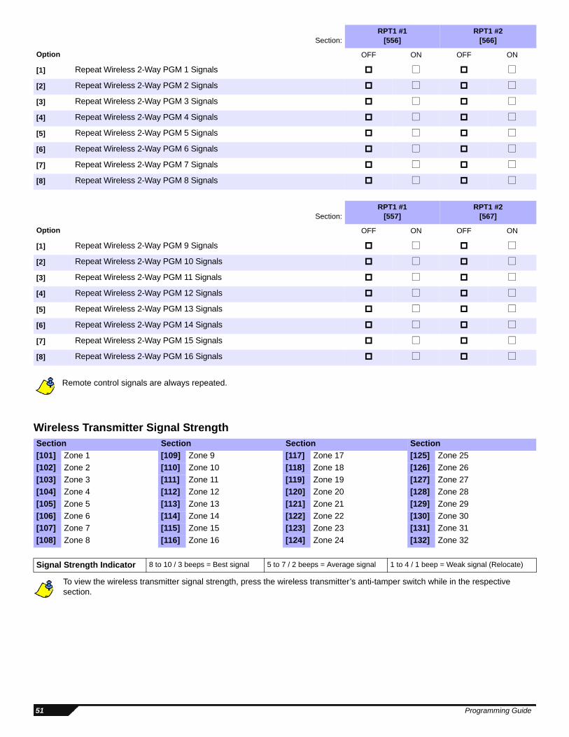
Remote control signals are always repeated.
Wireless Transmitter Signal Strength
To view the wireless transmitter signal strength, press the wireless transmitter’s anti-tamper switch while in the respective section.
Section:RPT1 #1
[556]RPT1 #2
[566]
Option OFF ON OFF ON
[1] Repeat Wireless 2-Way PGM 1 Signals
[2] Repeat Wireless 2-Way PGM 2 Signals
[3] Repeat Wireless 2-Way PGM 3 Signals
[4] Repeat Wireless 2-Way PGM 4 Signals
[5] Repeat Wireless 2-Way PGM 5 Signals
[6] Repeat Wireless 2-Way PGM 6 Signals
[7] Repeat Wireless 2-Way PGM 7 Signals
[8] Repeat Wireless 2-Way PGM 8 Signals
Section:RPT1 #1
[557]RPT1 #2
[567]
Option OFF ON OFF ON
[1] Repeat Wireless 2-Way PGM 9 Signals
[2] Repeat Wireless 2-Way PGM 10 Signals
[3] Repeat Wireless 2-Way PGM 11 Signals
[4] Repeat Wireless 2-Way PGM 12 Signals
[5] Repeat Wireless 2-Way PGM 13 Signals
[6] Repeat Wireless 2-Way PGM 14 Signals
[7] Repeat Wireless 2-Way PGM 15 Signals
[8] Repeat Wireless 2-Way PGM 16 Signals
Section Section Section Section[101] Zone 1 [109] Zone 9 [117] Zone 17 [125] Zone 25[102] Zone 2 [110] Zone 10 [118] Zone 18 [126] Zone 26[103] Zone 3 [111] Zone 11 [119] Zone 19 [127] Zone 27[104] Zone 4 [112] Zone 12 [120] Zone 20 [128] Zone 28[105] Zone 5 [113] Zone 13 [121] Zone 21 [129] Zone 29[106] Zone 6 [114] Zone 14 [122] Zone 22 [130] Zone 30[107] Zone 7 [115] Zone 15 [123] Zone 23 [131] Zone 31[108] Zone 8 [116] Zone 16 [124] Zone 24 [132] Zone 32
Signal Strength Indicator 8 to 10 / 3 beeps = Best signal 5 to 7 / 2 beeps = Average signal 1 to 4 / 1 beep = Weak signal (Relocate)
51 Programming Guide
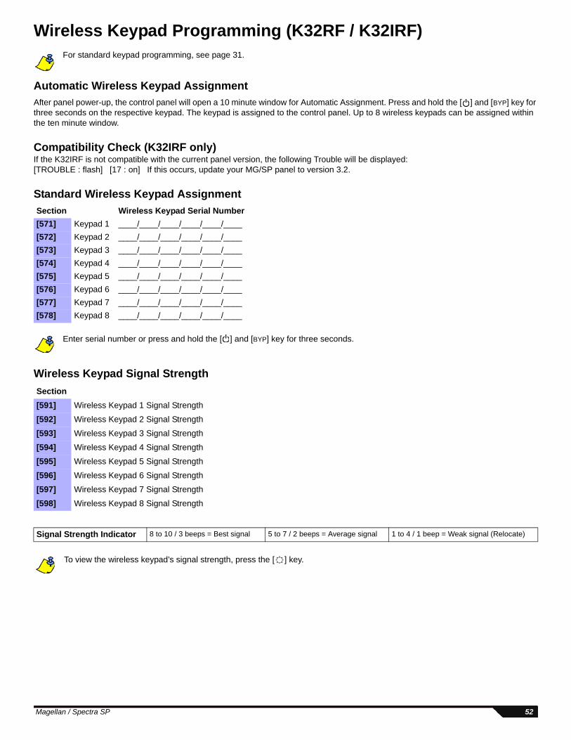
Wireless Keypad Programming (K32RF / K32IRF)For standard keypad programming, see page 31.
Automatic Wireless Keypad AssignmentAfter panel power-up, the control panel will open a 10 minute window for Automatic Assignment. Press and hold the [ ] and [BYP] key for three seconds on the respective keypad. The keypad is assigned to the control panel. Up to 8 wireless keypads can be assigned within the ten minute window.
Compatibility Check (K32IRF only)If the K32IRF is not compatible with the current panel version, the following Trouble will be displayed:[TROUBLE : flash] [17 : on] If this occurs, update your MG/SP panel to version 3.2.
Standard Wireless Keypad Assignment
Enter serial number or press and hold the [ ] and [BYP] key for three seconds.
Wireless Keypad Signal Strength
To view the wireless keypad’s signal strength, press the [ ] key.
Section Wireless Keypad Serial Number[571] Keypad 1 ____/____/____/____/____/____[572] Keypad 2 ____/____/____/____/____/____[573] Keypad 3 ____/____/____/____/____/____[574] Keypad 4 ____/____/____/____/____/____[575] Keypad 5 ____/____/____/____/____/____[576] Keypad 6 ____/____/____/____/____/____[577] Keypad 7 ____/____/____/____/____/____[578] Keypad 8 ____/____/____/____/____/____
Section[591] Wireless Keypad 1 Signal Strength
[592] Wireless Keypad 2 Signal Strength
[593] Wireless Keypad 3 Signal Strength
[594] Wireless Keypad 4 Signal Strength
[595] Wireless Keypad 5 Signal Strength
[596] Wireless Keypad 6 Signal Strength
[597] Wireless Keypad 7 Signal Strength
[598] Wireless Keypad 8 Signal Strength
Signal Strength Indicator 8 to 10 / 3 beeps = Best signal 5 to 7 / 2 beeps = Average signal 1 to 4 / 1 beep = Weak signal (Relocate)
Magellan / Spectra SP 52
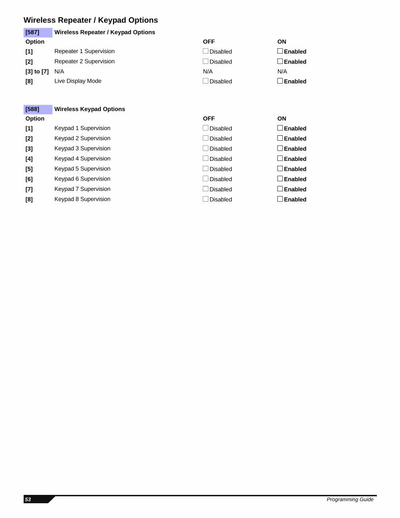
Wireless Repeater / Keypad Options[587] Wireless Repeater / Keypad OptionsOption OFF ON[1] Repeater 1 Supervision Disabled Enabled[2] Repeater 2 Supervision Disabled Enabled[3] to [7] N/A N/A N/A
[8] Live Display Mode Disabled Enabled
[588] Wireless Keypad OptionsOption OFF ON[1] Keypad 1 Supervision Disabled Enabled[2] Keypad 2 Supervision Disabled Enabled[3] Keypad 3 Supervision Disabled Enabled[4] Keypad 4 Supervision Disabled Enabled[5] Keypad 5 Supervision Disabled Enabled[6] Keypad 6 Supervision Disabled Enabled[7] Keypad 7 Supervision Disabled Enabled[8] Keypad 8 Supervision Disabled Enabled
53 Programming Guide
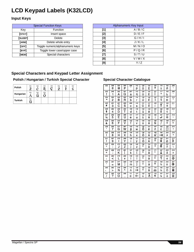
LCD Keypad Labels (K32LCD)Input Keys
Special Characters and Keypad Letter Assignment
Alphanumeric Key Input[1] A / B / C[2] D / E / F[3] G / H / I[4] J / K / L[5] M / N / O[6] P / Q / R[7] S / T / U[8] V / W / X[9] Y / Z
Special Function KeysKey Function
[STAY] Insert space[SLEEP] Delete[ARM] Delete whole entry[OFF] Toggle numeric/alphanumeric keys[BYP] Toggle lower case/upper case[MEM] Special characters
Polish001 002 003 004 005 006 007
Hungarian001 002 003
Turkish001
Special Character CataloguePolish / Hungarian / Turkish Special Character
Magellan / Spectra SP 54
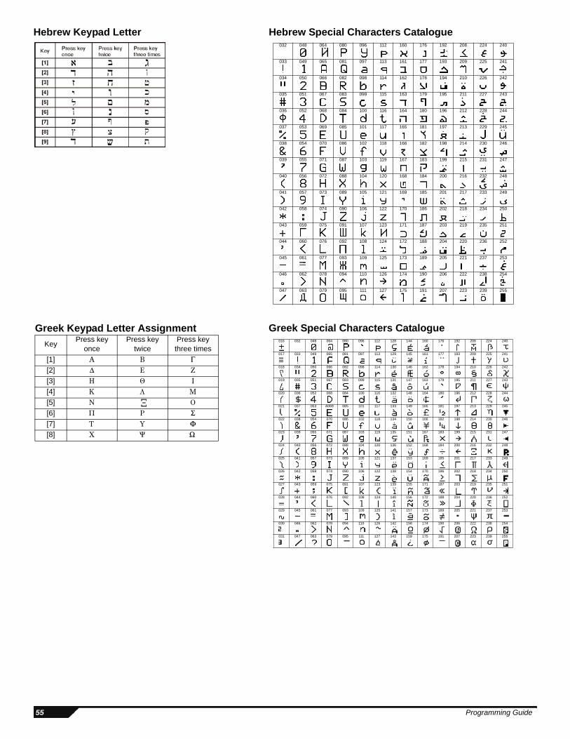
Hebrew Keypad Letter Hebrew Special Characters Catalogue032 048 064 080 096 112 160 176 192 208 224 240
033 049 065 081 097 113 161 177 193 209 225 241
034 050 066 082 098 114 162 178 194 210 226 242
035 051 067 083 099 115 163 179 195 211 227 243
036 052 068 084 100 116 164 180 196 212 228 244
037 053 069 085 101 117 165 181 197 213 229 245
038 054 070 086 102 118 166 182 198 214 230 246
039 055 071 087 103 119 167 183 199 215 231 247
040 056 072 088 104 120 168 184 200 216 232 248
041 057 073 089 105 121 169 185 201 217 233 249
042 058 074 090 106 122 170 186 202 218 234 250
043 059 075 091 107 123 171 187 203 219 235 251
044 060 076 092 108 124 172 188 204 220 236 252
045 061 077 093 109 125 173 189 205 221 237 253
046 062 078 094 110 126 174 190 206 222 238 254
047 063 079 095 111 127 175 191 207 223 239 255
Greek Keypad Letter AssignmentKey Press key
oncePress key
twicePress key
three times[1][2][3][4][5][6][7][8]
Greek Special Characters Catalogue016 032 048 064 080 096 112 128 144 160 176 192 208 224 240
017 033 049 065 081 097 113 129 145 161 177 193 209 225 241
018 034 050 066 082 098 114 130 146 162 178 194 210 226 242
019 035 051 067 083 099 115 131 147 163 179 195 211 227 243
020 036 052 068 084 100 116 132 148 164 180 196 212 228 244
021 037 053 A069 085 101 117 133 149 165 181 197 213 229 245
022 038 054 070 086 102 118 134 150 166 182 198 214 230 246
023 039 055 071 087 103 119 135 151 167 183 199 215 231 247
024 040 056 072 088 104 120 136 152 168 184 200 216 232 248
025 041 057 073 089 105 121 137 153 169 185 201 217 233 249
026 042 058 074 090 106 122 138 154 170 186 202 218 234 250
027 043 059 075 091 107 123 139 155 171 187 203 219 235 251
028 044 060 076 092 108 124 140 156 172 188 204 220 236 252
029 045 061 077 093 109 125 141 157 173 189 205 221 237 253
030 046 062 078 094 110 126 142 158 174 190 206 222 238 254
031 047 063 079 095 111 127 143 159 175 191 207 223 239 255
55 Programming Guide
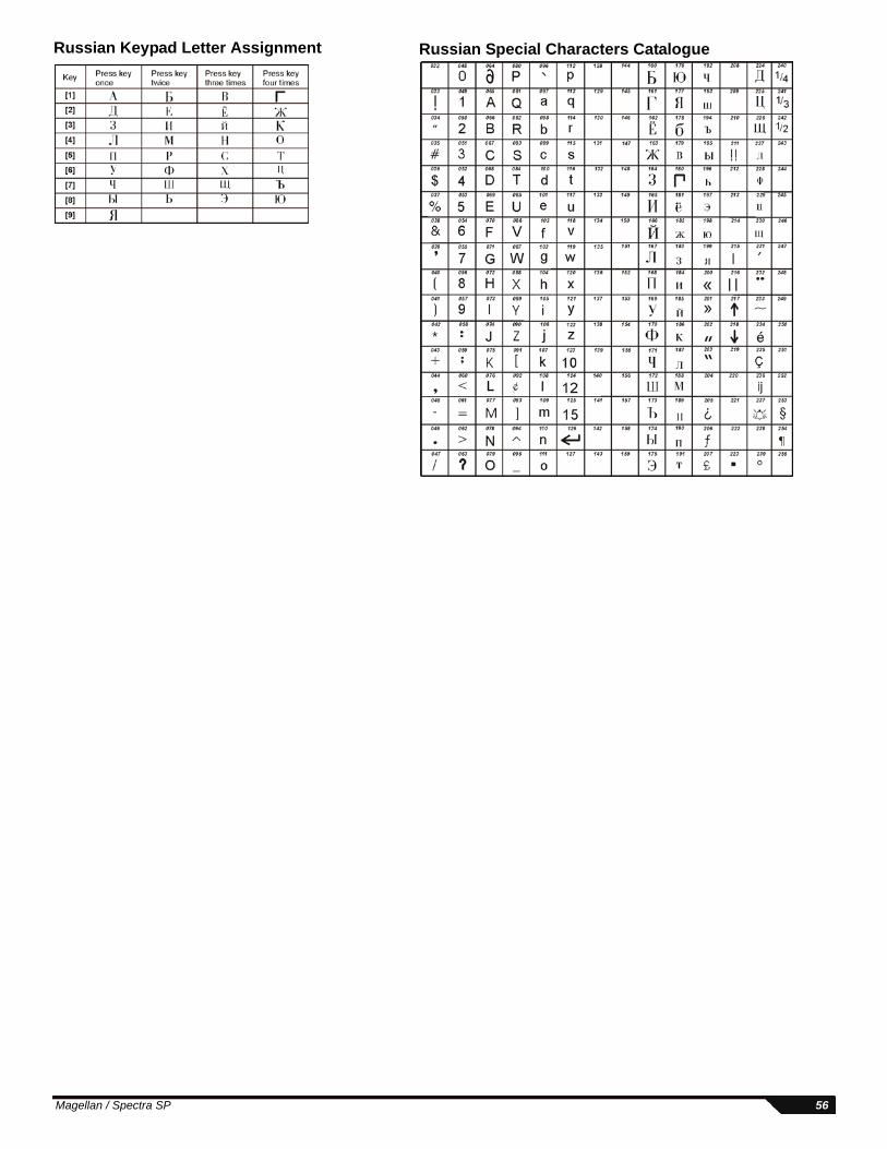
Russian Special Characters CatalogueRussian Keypad Letter Assignment
Magellan / Spectra SP 56
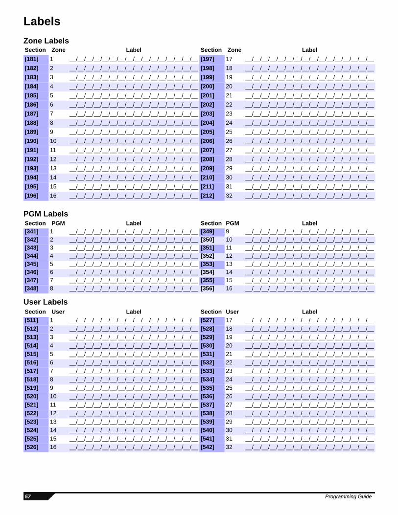
LabelsZone Labels
PGM Labels
User Labels
Section Zone Label Section Zone Label[181] 1 __/__/__/__/__/__/__/__/__/__/__/__/__/__/__/__ [197] 17 __/__/__/__/__/__/__/__/__/__/__/__/__/__/__/__[182] 2 __/__/__/__/__/__/__/__/__/__/__/__/__/__/__/__ [198] 18 __/__/__/__/__/__/__/__/__/__/__/__/__/__/__/__[183] 3 __/__/__/__/__/__/__/__/__/__/__/__/__/__/__/__ [199] 19 __/__/__/__/__/__/__/__/__/__/__/__/__/__/__/__[184] 4 __/__/__/__/__/__/__/__/__/__/__/__/__/__/__/__ [200] 20 __/__/__/__/__/__/__/__/__/__/__/__/__/__/__/__[185] 5 __/__/__/__/__/__/__/__/__/__/__/__/__/__/__/__ [201] 21 __/__/__/__/__/__/__/__/__/__/__/__/__/__/__/__[186] 6 __/__/__/__/__/__/__/__/__/__/__/__/__/__/__/__ [202] 22 __/__/__/__/__/__/__/__/__/__/__/__/__/__/__/__[187] 7 __/__/__/__/__/__/__/__/__/__/__/__/__/__/__/__ [203] 23 __/__/__/__/__/__/__/__/__/__/__/__/__/__/__/__[188] 8 __/__/__/__/__/__/__/__/__/__/__/__/__/__/__/__ [204] 24 __/__/__/__/__/__/__/__/__/__/__/__/__/__/__/__[189] 9 __/__/__/__/__/__/__/__/__/__/__/__/__/__/__/__ [205] 25 __/__/__/__/__/__/__/__/__/__/__/__/__/__/__/__[190] 10 __/__/__/__/__/__/__/__/__/__/__/__/__/__/__/__ [206] 26 __/__/__/__/__/__/__/__/__/__/__/__/__/__/__/__[191] 11 __/__/__/__/__/__/__/__/__/__/__/__/__/__/__/__ [207] 27 __/__/__/__/__/__/__/__/__/__/__/__/__/__/__/__[192] 12 __/__/__/__/__/__/__/__/__/__/__/__/__/__/__/__ [208] 28 __/__/__/__/__/__/__/__/__/__/__/__/__/__/__/__[193] 13 __/__/__/__/__/__/__/__/__/__/__/__/__/__/__/__ [209] 29 __/__/__/__/__/__/__/__/__/__/__/__/__/__/__/__[194] 14 __/__/__/__/__/__/__/__/__/__/__/__/__/__/__/__ [210] 30 __/__/__/__/__/__/__/__/__/__/__/__/__/__/__/__[195] 15 __/__/__/__/__/__/__/__/__/__/__/__/__/__/__/__ [211] 31 __/__/__/__/__/__/__/__/__/__/__/__/__/__/__/__[196] 16 __/__/__/__/__/__/__/__/__/__/__/__/__/__/__/__ [212] 32 __/__/__/__/__/__/__/__/__/__/__/__/__/__/__/__
Section PGM Label Section PGM Label[341] 1 __/__/__/__/__/__/__/__/__/__/__/__/__/__/__/__ [349] 9 __/__/__/__/__/__/__/__/__/__/__/__/__/__/__/__[342] 2 __/__/__/__/__/__/__/__/__/__/__/__/__/__/__/__ [350] 10 __/__/__/__/__/__/__/__/__/__/__/__/__/__/__/__[343] 3 __/__/__/__/__/__/__/__/__/__/__/__/__/__/__/__ [351] 11 __/__/__/__/__/__/__/__/__/__/__/__/__/__/__/__[344] 4 __/__/__/__/__/__/__/__/__/__/__/__/__/__/__/__ [352] 12 __/__/__/__/__/__/__/__/__/__/__/__/__/__/__/__[345] 5 __/__/__/__/__/__/__/__/__/__/__/__/__/__/__/__ [353] 13 __/__/__/__/__/__/__/__/__/__/__/__/__/__/__/__[346] 6 __/__/__/__/__/__/__/__/__/__/__/__/__/__/__/__ [354] 14 __/__/__/__/__/__/__/__/__/__/__/__/__/__/__/__[347] 7 __/__/__/__/__/__/__/__/__/__/__/__/__/__/__/__ [355] 15 __/__/__/__/__/__/__/__/__/__/__/__/__/__/__/__[348] 8 __/__/__/__/__/__/__/__/__/__/__/__/__/__/__/__ [356] 16 __/__/__/__/__/__/__/__/__/__/__/__/__/__/__/__
Section User Label Section User Label[511] 1 __/__/__/__/__/__/__/__/__/__/__/__/__/__/__/__ [527] 17 __/__/__/__/__/__/__/__/__/__/__/__/__/__/__/__[512] 2 __/__/__/__/__/__/__/__/__/__/__/__/__/__/__/__ [528] 18 __/__/__/__/__/__/__/__/__/__/__/__/__/__/__/__[513] 3 __/__/__/__/__/__/__/__/__/__/__/__/__/__/__/__ [529] 19 __/__/__/__/__/__/__/__/__/__/__/__/__/__/__/__[514] 4 __/__/__/__/__/__/__/__/__/__/__/__/__/__/__/__ [530] 20 __/__/__/__/__/__/__/__/__/__/__/__/__/__/__/__[515] 5 __/__/__/__/__/__/__/__/__/__/__/__/__/__/__/__ [531] 21 __/__/__/__/__/__/__/__/__/__/__/__/__/__/__/__[516] 6 __/__/__/__/__/__/__/__/__/__/__/__/__/__/__/__ [532] 22 __/__/__/__/__/__/__/__/__/__/__/__/__/__/__/__[517] 7 __/__/__/__/__/__/__/__/__/__/__/__/__/__/__/__ [533] 23 __/__/__/__/__/__/__/__/__/__/__/__/__/__/__/__[518] 8 __/__/__/__/__/__/__/__/__/__/__/__/__/__/__/__ [534] 24 __/__/__/__/__/__/__/__/__/__/__/__/__/__/__/__[519] 9 __/__/__/__/__/__/__/__/__/__/__/__/__/__/__/__ [535] 25 __/__/__/__/__/__/__/__/__/__/__/__/__/__/__/__[520] 10 __/__/__/__/__/__/__/__/__/__/__/__/__/__/__/__ [536] 26 __/__/__/__/__/__/__/__/__/__/__/__/__/__/__/__[521] 11 __/__/__/__/__/__/__/__/__/__/__/__/__/__/__/__ [537] 27 __/__/__/__/__/__/__/__/__/__/__/__/__/__/__/__[522] 12 __/__/__/__/__/__/__/__/__/__/__/__/__/__/__/__ [538] 28 __/__/__/__/__/__/__/__/__/__/__/__/__/__/__/__[523] 13 __/__/__/__/__/__/__/__/__/__/__/__/__/__/__/__ [539] 29 __/__/__/__/__/__/__/__/__/__/__/__/__/__/__/__[524] 14 __/__/__/__/__/__/__/__/__/__/__/__/__/__/__/__ [540] 30 __/__/__/__/__/__/__/__/__/__/__/__/__/__/__/__[525] 15 __/__/__/__/__/__/__/__/__/__/__/__/__/__/__/__ [541] 31 __/__/__/__/__/__/__/__/__/__/__/__/__/__/__/__[526] 16 __/__/__/__/__/__/__/__/__/__/__/__/__/__/__/__ [542] 32 __/__/__/__/__/__/__/__/__/__/__/__/__/__/__/__
57 Programming Guide
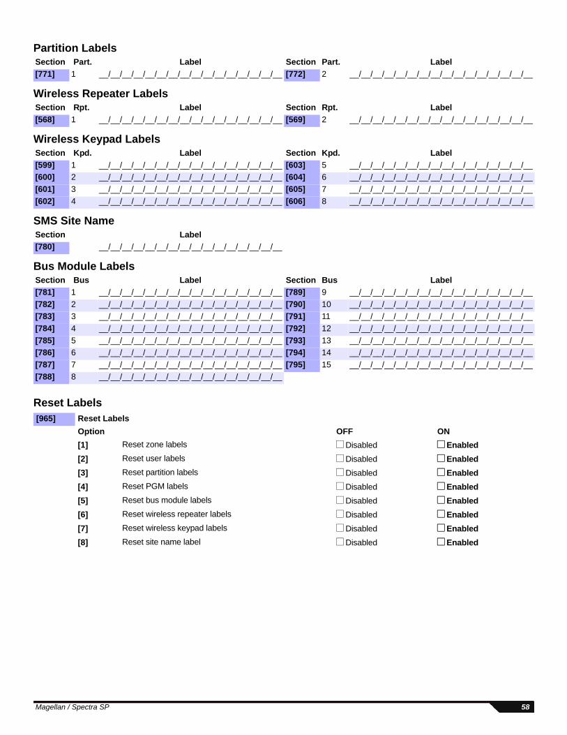
Partition Labels
Wireless Repeater Labels
Wireless Keypad Labels
SMS Site Name
Bus Module Labels
Reset Labels
Section Part. Label Section Part. Label[771] 1 __/__/__/__/__/__/__/__/__/__/__/__/__/__/__/__ [772] 2 __/__/__/__/__/__/__/__/__/__/__/__/__/__/__/__
Section Rpt. Label Section Rpt. Label[568] 1 __/__/__/__/__/__/__/__/__/__/__/__/__/__/__/__ [569] 2 __/__/__/__/__/__/__/__/__/__/__/__/__/__/__/__
Section Kpd. Label Section Kpd. Label[599] 1 __/__/__/__/__/__/__/__/__/__/__/__/__/__/__/__ [603] 5 __/__/__/__/__/__/__/__/__/__/__/__/__/__/__/__[600] 2 __/__/__/__/__/__/__/__/__/__/__/__/__/__/__/__ [604] 6 __/__/__/__/__/__/__/__/__/__/__/__/__/__/__/__[601] 3 __/__/__/__/__/__/__/__/__/__/__/__/__/__/__/__ [605] 7 __/__/__/__/__/__/__/__/__/__/__/__/__/__/__/__[602] 4 __/__/__/__/__/__/__/__/__/__/__/__/__/__/__/__ [606] 8 __/__/__/__/__/__/__/__/__/__/__/__/__/__/__/__
Section Label[780] __/__/__/__/__/__/__/__/__/__/__/__/__/__/__/__
Section Bus Label Section Bus Label[781] 1 __/__/__/__/__/__/__/__/__/__/__/__/__/__/__/__ [789] 9 __/__/__/__/__/__/__/__/__/__/__/__/__/__/__/__[782] 2 __/__/__/__/__/__/__/__/__/__/__/__/__/__/__/__ [790] 10 __/__/__/__/__/__/__/__/__/__/__/__/__/__/__/__[783] 3 __/__/__/__/__/__/__/__/__/__/__/__/__/__/__/__ [791] 11 __/__/__/__/__/__/__/__/__/__/__/__/__/__/__/__[784] 4 __/__/__/__/__/__/__/__/__/__/__/__/__/__/__/__ [792] 12 __/__/__/__/__/__/__/__/__/__/__/__/__/__/__/__[785] 5 __/__/__/__/__/__/__/__/__/__/__/__/__/__/__/__ [793] 13 __/__/__/__/__/__/__/__/__/__/__/__/__/__/__/__[786] 6 __/__/__/__/__/__/__/__/__/__/__/__/__/__/__/__ [794] 14 __/__/__/__/__/__/__/__/__/__/__/__/__/__/__/__[787] 7 __/__/__/__/__/__/__/__/__/__/__/__/__/__/__/__ [795] 15 __/__/__/__/__/__/__/__/__/__/__/__/__/__/__/__[788] 8 __/__/__/__/__/__/__/__/__/__/__/__/__/__/__/__
[965] Reset LabelsOption OFF ON[1] Reset zone labels Disabled Enabled[2] Reset user labels Disabled Enabled[3] Reset partition labels Disabled Enabled[4] Reset PGM labels Disabled Enabled[5] Reset bus module labels Disabled Enabled[6] Reset wireless repeater labels Disabled Enabled[7] Reset wireless keypad labels Disabled Enabled[8] Reset site name label Disabled Enabled
Magellan / Spectra SP 58
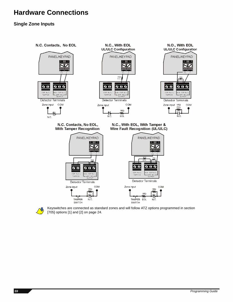
Hardware ConnectionsSingle Zone Inputs
Keyswitches are connected as standard zones and will follow ATZ options programmed in section [705] options [1] and [2] on page 24.
59 Programming Guide
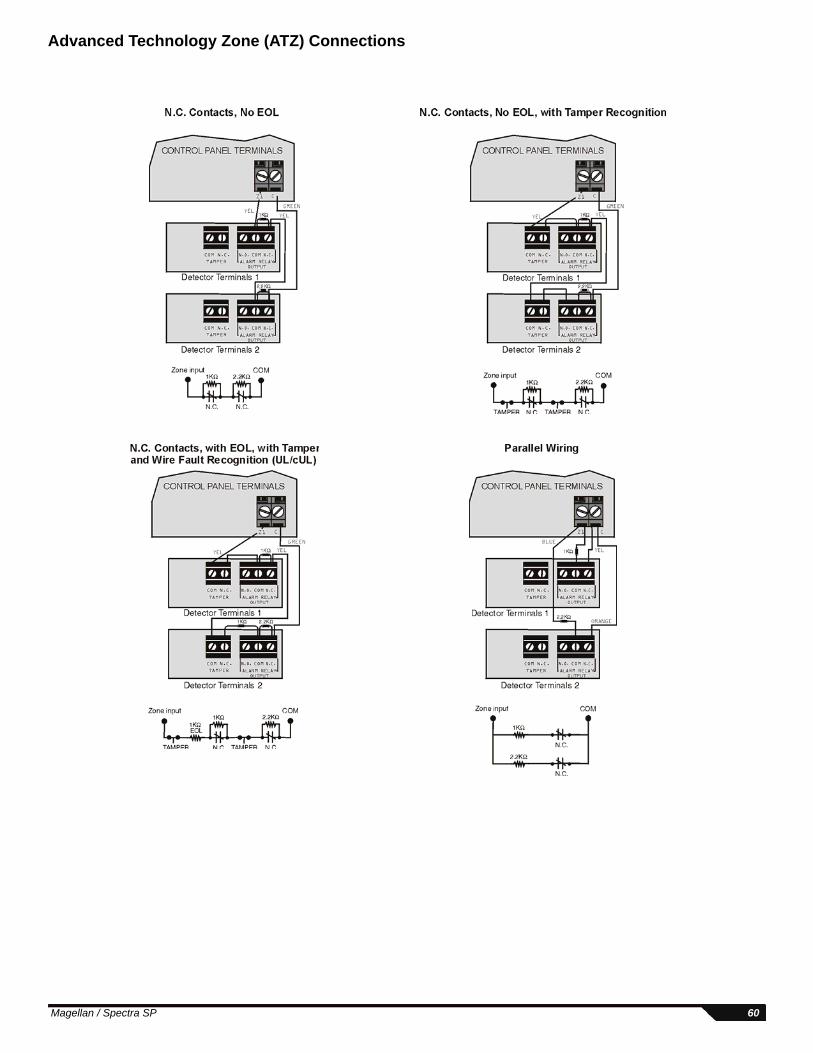
Advanced Technology Zone (ATZ) Connections
Magellan / Spectra SP 60
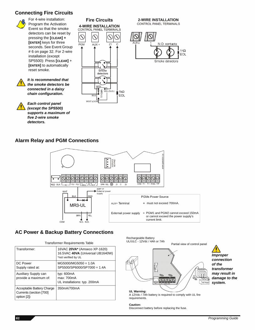
Connecting Fire Circuits
Alarm Relay and PGM Connections
AC Power & Backup Battery Connections
Transformer Requirements Table Transformer: 16VAC 20VA* (Amseco XP-1620)
16.5VAC 40VA (Universal UB1640W)*not verified by UL
DC PowerSupply rated at:
MG5000/MG5050 = 1.0ASP5500/SP6000/SP7000 = 1.4A
Auxiliary Supply can provide a maximum of:
typ: 600mAmax: 700mAUL installations: typ. 200mA
Acceptable Battery Charge Currents (section [700] option [2])
350mA/700mA
For 4-wire installation: Program the Activation Event so that the smoke detectors can be reset by pressing the [CLEAR] + [ENTER] keys for three seconds. See Event Group # 6 on page 32. For 2-wire installation (except SP5500): Press [CLEAR] + [ENTER] to automatically reset smoke.
It is recommended that the smoke detectors be connected in a daisy chain configuration.
Each control panel (except the SP5500) supports a maximum of five 2-wire smoke detectors.
must not exceed 700mA.
PGM1 and PGM2 cannot exceed 150mA or cannot exceed the power supply’s current limit.
Partial view of control panel
UL Warning: A 12Vdc / 7Ah battery is required to comply with UL fire requirements.
Caution:Disconnect battery before replacing the fuse.
Rechargeable BatteryUL/ULC - 12Vdc / 4Ah or 7Ah
Improper connection of the transformer may result in damage to the system.
61 Programming Guide

Connecting to WinLoad
Updating Firmware Using WinLoadTo update your system firmware:
1. Connect the product to your computer using a 307USB Direct Connect Interface or CONV4USB Converter.
2. Start WinLoad Installer Upload/Download Software.
3. Click the In-field Programmer button.
4. Verify the product information located in the In-Field Firmware Programmer window.If the firmware programmer does not automatically detect your control panel, click the Com port settings button and select the correct Com port. Then click the Refresh Product Info button to connect with the panel.
5. To check for new updates, click the Download Firmware from the web button.
6. From the Select Firmware drop-down box, select the firmware version you wish to install.orIf you have already downloaded the .pef file from paradox.com, click the [...] button and select the location of the .pef file.
7. Click the Update product firmware button.
When the download process finishes, the update is complete.
Serial Connector
Computer containing WinLoad software
307 adapter/CONV4USB
Converter
4-pin connector
cable
Standard DB-9 cable (9-pin serial
cable)
Magellan / Spectra SP 62
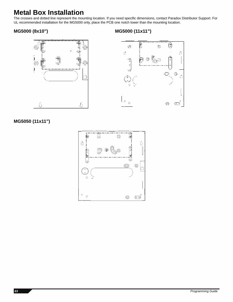
Metal Box InstallationThe crosses and dotted line represent the mounting location. If you need specific dimensions, contact Paradox Distributor Support. For UL recommended installation for the MG5000 only, place the PCB one notch lower than the mounting location.
MG5000 (8x10”) MG5000 (11x11”)
MG5050 (11x11”)
63 Programming Guide

SP5500 (8x10”)
SP6000 (11x11”)
SP7000 (11x11”)
Magellan / Spectra SP 64
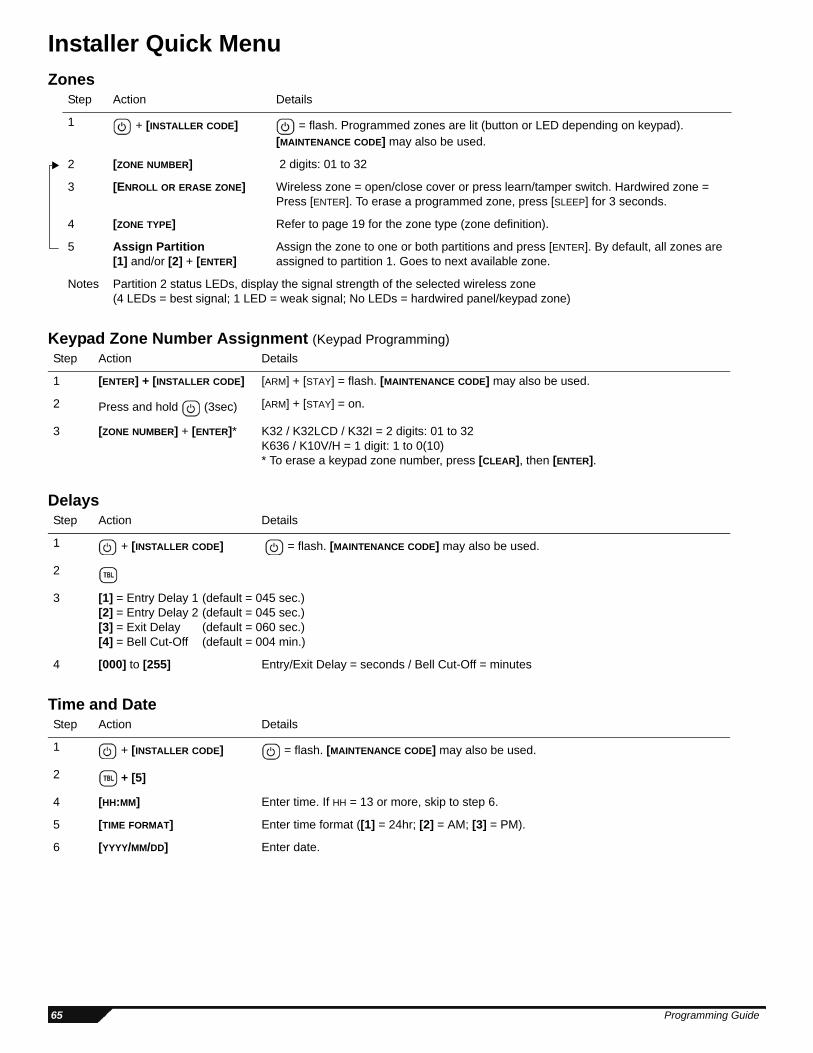
Installer Quick MenuZones
Keypad Zone Number Assignment (Keypad Programming)
Delays
Time and Date
Step Action Details
1 + [INSTALLER CODE] = flash. Programmed zones are lit (button or LED depending on keypad).[MAINTENANCE CODE] may also be used.
2 [ZONE NUMBER] 2 digits: 01 to 32
3 [ENROLL OR ERASE ZONE] Wireless zone = open/close cover or press learn/tamper switch. Hardwired zone = Press [ENTER]. To erase a programmed zone, press [SLEEP] for 3 seconds.
4 [ZONE TYPE] Refer to page 19 for the zone type (zone definition).
5 Assign Partition [1] and/or [2] + [ENTER]
Assign the zone to one or both partitions and press [ENTER]. By default, all zones are assigned to partition 1. Goes to next available zone.
Notes Partition 2 status LEDs, display the signal strength of the selected wireless zone (4 LEDs = best signal; 1 LED = weak signal; No LEDs = hardwired panel/keypad zone)
Step Action Details
1 [ENTER] + [INSTALLER CODE] [ARM] + [STAY] = flash. [MAINTENANCE CODE] may also be used.
2 Press and hold (3sec) [ARM] + [STAY] = on.
3 [ZONE NUMBER] + [ENTER]* K32 / K32LCD / K32I = 2 digits: 01 to 32K636 / K10V/H = 1 digit: 1 to 0(10)* To erase a keypad zone number, press [CLEAR], then [ENTER].
Step Action Details
1 + [INSTALLER CODE] = flash. [MAINTENANCE CODE] may also be used.
2
3 [1] = Entry Delay 1 (default = 045 sec.)[2] = Entry Delay 2 (default = 045 sec.)[3] = Exit Delay (default = 060 sec.)[4] = Bell Cut-Off (default = 004 min.)
4 [000] to [255] Entry/Exit Delay = seconds / Bell Cut-Off = minutes
Step Action Details
1 + [INSTALLER CODE] = flash. [MAINTENANCE CODE] may also be used.
2 + [5]
4 [HH:MM] Enter time. If HH = 13 or more, skip to step 6.
5 [TIME FORMAT] Enter time format ([1] = 24hr; [2] = AM; [3] = PM).
6 [YYYY/MM/DD] Enter date.
65 Programming Guide
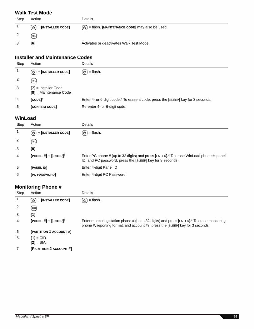
Walk Test Mode
Installer and Maintenance Codes
WinLoad
Monitoring Phone #
Step Action Details
1 + [INSTALLER CODE] = flash. [MAINTENANCE CODE] may also be used.
2
3 [6] Activates or deactivates Walk Test Mode.
Step Action Details
1 + [INSTALLER CODE] = flash.
2
3 [7] = Installer Code[8] = Maintenance Code
4 [CODE]* Enter 4- or 6-digit code.* To erase a code, press the [SLEEP] key for 3 seconds.
5 [CONFIRM CODE] Re-enter 4- or 6-digit code.
Step Action Details
1 + [INSTALLER CODE] = flash.
2
3 [9]
4 [PHONE #] + [ENTER]* Enter PC phone # (up to 32 digits) and press [ENTER].* To erase WinLoad phone #, panel ID, and PC password, press the [SLEEP] key for 3 seconds.
5 [PANEL ID] Enter 4-digit Panel ID
6 [PC PASSWORD] Enter 4-digit PC Password
Step Action Details
1 + [INSTALLER CODE] = flash.
2
3 [1]4 [PHONE #] + [ENTER]* Enter monitoring station phone # (up to 32 digits) and press [ENTER].* To erase monitoring
phone #, reporting format, and account #s, press the [SLEEP] key for 3 seconds.
5 [PARTITION 1 ACCOUNT #]6 [1] = CID
[2] = SIA
7 [PARTITION 2 ACCOUNT #]
Magellan / Spectra SP 66
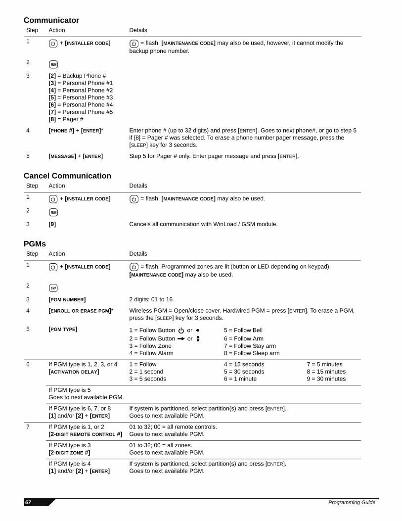
Communicator
Cancel Communication
PGMs
Step Action Details
1 + [INSTALLER CODE] = flash. [MAINTENANCE CODE] may also be used, however, it cannot modify the backup phone number.
2
3 [2] = Backup Phone #[3] = Personal Phone #1[4] = Personal Phone #2[5] = Personal Phone #3[6] = Personal Phone #4[7] = Personal Phone #5[8] = Pager #
4 [PHONE #] + [ENTER]* Enter phone # (up to 32 digits) and press [ENTER]. Goes to next phone#, or go to step 5 if [8] = Pager # was selected. To erase a phone number pager message, press the [SLEEP] key for 3 seconds.
5 [MESSAGE] + [ENTER] Step 5 for Pager # only. Enter pager message and press [ENTER].
Step Action Details
1 + [INSTALLER CODE] = flash. [MAINTENANCE CODE] may also be used.
2
3 [9] Cancels all communication with WinLoad / GSM module.
Step Action Details
1 + [INSTALLER CODE] = flash. Programmed zones are lit (button or LED depending on keypad).[MAINTENANCE CODE] may also be used.
2
3 [PGM NUMBER] 2 digits: 01 to 16
4 [ENROLL OR ERASE PGM]* Wireless PGM = Open/close cover. Hardwired PGM = press [ENTER]. To erase a PGM, press the [SLEEP] key for 3 seconds.
5 [PGM TYPE] 1 = Follow Button or 5 = Follow Bell2 = Follow Button or 6 = Follow Arm3 = Follow Zone 7 = Follow Stay arm4 = Follow Alarm 8 = Follow Sleep arm
6 If PGM type is 1, 2, 3, or 4 [ACTIVATION DELAY]
1 = Follow 4 = 15 seconds 7 = 5 minutes2 = 1 second 5 = 30 seconds 8 = 15 minutes3 = 5 seconds 6 = 1 minute 9 = 30 minutes
If PGM type is 5Goes to next available PGM.
If PGM type is 6, 7, or 8[1] and/or [2] + [ENTER]
If system is partitioned, select partition(s) and press [ENTER]. Goes to next available PGM.
7 If PGM type is 1, or 2 [2-DIGIT REMOTE CONTROL #]
01 to 32; 00 = all remote controls. Goes to next available PGM.
If PGM type is 3 [2-DIGIT ZONE #]
01 to 32; 00 = all zones. Goes to next available PGM.
If PGM type is 4 [1] and/or [2] + [ENTER]
If system is partitioned, select partition(s) and press [ENTER]. Goes to next available PGM.
67 Programming Guide
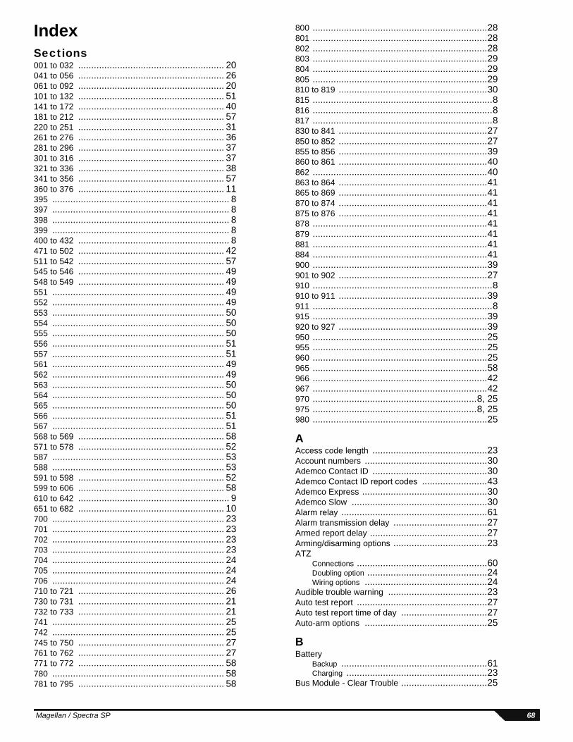
IndexSections001 to 032 ........................................................ 20041 to 056 ........................................................ 26061 to 092 ........................................................ 20101 to 132 ........................................................ 51141 to 172 ........................................................ 40181 to 212 ........................................................ 57220 to 251 ........................................................ 31261 to 276 ........................................................ 36281 to 296 ........................................................ 37301 to 316 ........................................................ 37321 to 336 ........................................................ 38341 to 356 ........................................................ 57360 to 376 ........................................................ 11395 .................................................................... 8397 .................................................................... 8398 .................................................................... 8399 .................................................................... 8400 to 432 .......................................................... 8471 to 502 ........................................................ 42511 to 542 ........................................................ 57545 to 546 ........................................................ 49548 to 549 ........................................................ 49551 .................................................................. 49552 .................................................................. 49553 .................................................................. 50554 .................................................................. 50555 .................................................................. 50556 .................................................................. 51557 .................................................................. 51561 .................................................................. 49562 .................................................................. 49563 .................................................................. 50564 .................................................................. 50565 .................................................................. 50566 .................................................................. 51567 .................................................................. 51568 to 569 ........................................................ 58571 to 578 ........................................................ 52587 .................................................................. 53588 .................................................................. 53591 to 598 ........................................................ 52599 to 606 ........................................................ 58610 to 642 .......................................................... 9651 to 682 ........................................................ 10700 .................................................................. 23701 .................................................................. 23702 .................................................................. 23703 .................................................................. 23704 .................................................................. 24705 .................................................................. 24706 .................................................................. 24710 to 721 ........................................................ 26730 to 731 ........................................................ 21732 to 733 ........................................................ 21741 .................................................................. 25742 .................................................................. 25745 to 750 ........................................................ 27761 to 762 ........................................................ 27771 to 772 ........................................................ 58780 .................................................................. 58781 to 795 ........................................................ 58
Magellan / Spectra SP
800 ...................................................................28801 ...................................................................28802 ...................................................................28803 ...................................................................29804 ...................................................................29805 ...................................................................29810 to 819 .........................................................30815 .....................................................................8816 .....................................................................8817 .....................................................................8830 to 841 .........................................................27850 to 852 .........................................................27855 to 856 .........................................................39860 to 861 .........................................................40862 ...................................................................40863 to 864 .........................................................41865 to 869 .........................................................41870 to 874 .........................................................41875 to 876 .........................................................41878 ...................................................................41879 ...................................................................41881 ...................................................................41884 ...................................................................41900 ...................................................................39901 to 902 .........................................................27910 .....................................................................8910 to 911 .........................................................39911 .....................................................................8915 ...................................................................39920 to 927 .........................................................39950 ...................................................................25955 ...................................................................25960 ...................................................................25965 ...................................................................58966 ...................................................................42967 ...................................................................42970 ...............................................................8, 25975 ...............................................................8, 25980 ...................................................................25
AAccess code length ............................................23Account numbers ...............................................30Ademco Contact ID ............................................30Ademco Contact ID report codes .........................43Ademco Express ................................................30Ademco Slow ....................................................30Alarm relay ........................................................61Alarm transmission delay ....................................27Armed report delay .............................................27Arming/disarming options ....................................23ATZ
Connections ..................................................60Doubling option ..............................................24Wiring options ...............................................24
Audible trouble warning ......................................23Auto test report ..................................................27Auto test report time of day .................................27Auto-arm options ...............................................25
BBattery
Backup ........................................................61Charging ......................................................23
Bus Module - Clear Trouble .................................25
68
CCancel communication ................................. 48, 67Check-in supervision time ................................... 24Clear Bus Module Trouble .................................. 25Communication
Programming ................................................ 28Settings ....................................................... 30
Communicator - quick menu ............................... 67Confidential mode ............................................. 23Contact ID override ............................................ 28
DData entry / display ............................................ 47Date and time ................................................... 65Daylight savings ................................................ 21Decimal and hexadecimal values ........................ 47Delay alarm transmission ................................... 27Delay between dialing attempts ........................... 27Delays - settings ................................................ 65Dialer options .................................................... 28Dialing - Delay between attempts ........................ 27Disarmed report delay ........................................ 27DTMF dialing .................................................... 28
EEntry delay - Display on LCD keypad ................... 23EOL resistors .................................................... 24Event call direction options ................................. 28Exit delay termination ......................................... 23
FFire circuits ....................................................... 61Firmware updating ............................................. 62
GGSM
No Service Timer ........................................... 39Options ....................................................... 29SMS Language ............................................. 39
HHardware connections ....................................... 59
IInstaller
Code ...................................................... 8, 66Code lock ...................................................... 8Function keys ............................................... 48Quick menu .................................................. 65
KKeypad
Labels (LCD) ................................................ 54Letters / Special characters .............................. 54Programming ................................................ 22Programming - wireless ................................... 52Zone number ................................................ 65
LLabels
Bus module .................................................. 58Partition ....................................................... 58PGM ........................................................... 57Reset .......................................................... 58SMS site name .............................................. 58User ........................................................... 57Wireless keypad ............................................ 58
69
Wireless repeater ...........................................58Zones ..........................................................57
LCD keypad labels .............................................54Lock master code ...............................................23
MMaintenance code ..........................................8, 66Maintenance code limited access table ...................8Master code lock ................................................23Memory key - download / upload .........................25Metal box installation ..........................................63Monitoring station
Maximum dialing attempts ................................27Telephone number ...................................30, 66
OOne-touch options ..............................................23
PPager reporting
Delay ..........................................................27Message repetition .........................................27
Panel version number .........................................25Panic options .....................................................23Partition labels ...................................................58Partition programming ........................................26Partitioning ........................................................23PCS100
Connection settings ........................................39Programming ................................................39SMS Language ..............................................39
Personal reportingDelay ..........................................................27Message repetition .........................................27
PGMConnections ..................................................61Delays .........................................................37Event description ............................................32Labels .........................................................57Options ........................................................36Programming ................................................31Quick menu ..................................................67Recognition ..................................................38Serial numbers ..............................................37Wireless signal strength ...................................38
PlanningSystem ........................................................13Wireless keypads ...........................................14Wireless system .............................................15
Power failure report delay ...................................27Programmable output
Options ........................................................36Programming ................................................31
QQuick menu .......................................................65
RRecent closing delay ..........................................27REM2 version number ........................................23REM3 - Action keys ............................................11Remote control
Action keys (REM3) ........................................11Button assignment ............................................9Serial number display ......................................25User assignment ............................................10
Remote controlsREM2 version number .....................................23
Ptogramming Guide
Report codeFormat ........................................................ 30
Report codesClear codes .................................................. 42Instructions .................................................. 40Reset codes ................................................. 42Special alarm ................................................ 41Special arming .............................................. 40Special disarming .......................................... 40System special .............................................. 41System trouble .............................................. 41System trouble restore .................................... 41User ........................................................... 42Zones ......................................................... 40
Reset codes and panel ........................................ 7Reset sections to factory default .......................... 25RF jamming supervision ..................................... 23RPT1 programming ........................................... 49
SSescoa ............................................................. 30SIA .................................................................. 30Signal strength - Wireless transmitter ................... 51Silent Knight Fast .............................................. 30Single zone inputs ............................................. 59SMS
Language .................................................... 39Site name .................................................... 58
StayDEntry point zone assignment ............................. 22
Supervision options ........................................... 24System master code ............................................ 8System specifications .......................... 1, 2, 3, 4, 5
TTamper recognition ............................................ 24Tamper supervision ........................................... 23Telephone number
Backup ....................................................... 30Monitoring station .......................................... 30Pager ......................................................... 30Special keys ................................................. 30
Test mode ........................................................ 48Test report ........................................................ 48Time and date ................................................... 65Timers
Auto-arm ..................................................... 27Confidential mode .......................................... 23Partition ....................................................... 27System ....................................................... 27
TLMFail delay ..................................................... 27
Trouble display .................................................. 48
UUser code options ............................................... 8User labels ....................................................... 57
VVDMP3
Calling the VDMP3 ......................................... 23Maximum voice dialing attempts ........................ 27
Version Numbers - Viewing .................................. 7
WWalk test mode ................................................. 66WinLoad
Answer/call software ....................................... 48
Magellan / Spectra SP
connecting ....................................................62Instructions ...................................................62Programming ................................................39Quick menu ..................................................66Through PCS100 ...........................................39
Wireless keypadAssignment ...................................................52Labels .........................................................58Options ........................................................53Programming ................................................52Signal strength ..............................................52
Wireless repeater / Keypad options ......................53Wireless repeater programming (RPT1) ................49
Labels .........................................................58Options ........................................................49Signal strength ..............................................49
Wireless transmitter signal strength ......................51
ZZone
Labels .........................................................56Programming ................................................17Recognition ..................................................17
Zone Definitions .................................................19ZX8 - zone/tamper .............................................24
70
WarrantyFor complete warranty information on this product please refer to the Limited Warranty Statement found on the website www.paradox.com/terms. Your use of the Paradox product signifies your acceptance of all warranty terms and conditions.
Limitations of Alarm Systems: It must be understood that while your Paradox alarm system is highly advanced and secure, it does not offer any guaranteed protection against burglary, fire or other emergency (fire and emergency options are only available on certain Paradox models). This is due to a number of reasons, including by not limited to inadequate or improper installation/positioning, sensor limitations, battery performance, wireless signal interruption, inadequate maintenance or the potential for the system or telephone lines to be compromised or circumvented. As a result, Paradox does not represent that the alarm system will prevent personal injury or property damage, or in all cases provide adequate warning or protection.
Your security system should therefore be considered as one of many tools available to reduce risk and/or damage of burglary, fire or other emergencies, such other tools include but are not limited to insurance coverage, fire prevention and extinguish devices, and sprinkler systems.
We also strongly recommend that you regularly maintain your security systems and stay aware of new and improved Paradox products and developments.
TBR-21: In order to comply with TBR-21, standard force dialing must be enabled.
UL AND ULC WARNINGS This equipment has the capability of being programmed with features not verified for use in UL installations. To stay within UL and ULC standards, the installer should use the following guidelines when configuring the system:• All components of the system should be UL listed for the intended application.• If used for “Fire” detection, the installer should refer to NFPA Standards #72, Chapter 2. In addition, once installation is complete, the local fire authority must be notified of
the installation.• WARNING: This equipment must be installed and maintained by qualified service personnel only• This equipment must be verified by a qualified technician once every three years.• All keypads must use an anti-tamper switch.• Do not bypass fire zones.• Maximum allowed entry delay is 45 seconds.• Maximum allowed exit delay is 60 seconds.• Minimum 4 minutes for bell cut-off time.• The following features do not comply with UL requirements: Bypass Recall and Auto Trouble Shutdown. • Do not connect the primary indicating device to a relay. The installer must use the bell output.• To comply with UL985, the auxiliary power output should not exceed 200mA. • Do not connect the zone ground terminal with UL Listed products.• The metallic enclosure must be grounded to the cold water pipe.• All outputs are Class 2 or power-limited, except for the battery terminal.The Class 2 and power-limited fire alarm circuits shall be installed using CL3, CL3R, CL3P, or
substitute cable permitted by the National Electrical Code, ANSI/NFPA 70.• EOL resistor part #2011002000• For UL Installations: Universal UB1640W 16.5VAC min 40VA• All outputs are rated from 11.3Vdc to 12.7Vdc• 12Vdc 4Ah rechargeable acid/lead or gel cell backup battery (YUASA model #NP7-12 recommended) for residential use. Use a 7Ah battery to comply with fire
requirements.• Wheelock 46T-12 siren
Legal© 2008 Paradox Security Systems Ltd. All rights reserved. Specifications may change without prior notice. One or more of the following US patents may apply: 7046142, 6215399, 6111256, 6104319, 5920259, 5886632, 5721542, 5287111, 5119069, 5077549 and RE39406. Canadian and international patents may also apply. Magellan and Spectra SP are trademarks or registered trademarks of Paradox Security Systems Ltd. or its affiliates in Canada, the United States and/or other countries.


For technical support in Canada or the U.S., call 1-800-791-1919, Monday to Friday from 8:00 a.m. to 8:00 p.m. EST. For technical support outside Canada and the U.S., call 00-1-450-491-7444, Monday to Friday from 8:00 a.m. to 8:00 p.m. EST.
Please feel free to visit our website at www.paradox.com
We hope this product performs to your complete satisfaction. Should you have any questions or comments, please visit www.paradox.com and send us your comments.
PARADOX.COMPrinted in Canada - 07/2008 MGSP-EP17


![MG5000 MG5050 SP65 SP4000 SP5500 SP6000 SP7000€¦ · [4] Communication Trouble Your alarm system, if monitored, could not communicate with the monitoring station. [5] Tamper/Zone](https://static.fdocuments.net/doc/165x107/607fa3b54cc96010ab14fc26/mg5000-mg5050-sp65-sp4000-sp5500-sp6000-sp7000-4-communication-trouble-your-alarm.jpg)