3.18 MEMS Atomic Clocks - NIST · Furthermore, it can be seen that atomic vapor cell clocks also...
42
3.18 MEMS Atomic Clocks Svenja Knappe, National Institute of Standards and Technology (NIST), Boulder, CO, USA Published by Elsevier B.V. 3.18.1 Introduction to MEMS Atomic Clocks 572 3.18.1.1 Introduction 572 3.18.1.2 Vapor Cell Atomic Clocks 573 3.18.1.3 Coherent Population Trapping 575 3.18.1.4 CPT in Small Vapor Cells 577 3.18.2 Design and Fabrication 578 3.18.2.1 Introduction 578 3.18.2.2 Physics Package 579 3.18.2.2.1 Introduction 579 3.18.2.2.2 Vertical-cavity surface-emitting laser 580 3.18.2.2.3 Vapor cells 581 3.18.2.2.4 Optics 584 3.18.2.2.5 Heating 585 3.18.2.2.6 Magnetic field control 586 3.18.2.3 Local Oscillator 587 3.18.2.3.1 Introduction 587 3.18.2.3.2 Oscillator designs for CSAC 588 3.18.2.3.3 Other MEMS resonators 588 3.18.2.4 Control Electronics 590 3.18.2.5 Packaging 591 3.18.3 Performance 592 3.18.3.1 Introduction 592 3.18.3.2 Frequency Stability 592 3.18.3.2.1 Introduction 592 3.18.3.2.2 Short-term frequency stability 594 3.18.3.2.3 Long-term frequency stability 595 3.18.3.3 Power Consumption 596 3.18.3.4 Size 597 3.18.4 Advanced Techniques 597 3.18.4.1 Introduction 597 3.18.4.2 Resonance Contrast 597 3.18.4.3 Buffer Gas 599 3.18.4.4 Spin Exchange 600 3.18.4.5 Noise Suppression 600 3.18.5 Other CSAC Approaches 600 3.18.5.1 Introduction 600 3.18.5.2 End-State CSAC 600 3.18.5.3 Nanomechanically Regulated CSAC 601 3.18.5.4 CPT Maser 601 3.18.5.5 Raman Oscillator 601 3.18.5.6 Ramsey-Type CPT Interrogation 602 3.18.5.7 N-Resonances 602 3.18.5.8 Others 603 3.18.6 Other MEMS Atomic Sensors 603 References 605 571 vol. 3, pp. - Comprehensive Microsystems, 571 612
Transcript of 3.18 MEMS Atomic Clocks - NIST · Furthermore, it can be seen that atomic vapor cell clocks also...

3.18 MEMS Atomic ClocksSvenja Knappe, National Institute of Standards and Technology (NIST), Boulder, CO, USA
Published by Elsevier B.V.
3.18.1 Introduction to MEMS Atomic Clocks
5723.18.1.1 Introduction
5723.18.1.2 Vapor Cell Atomic Clocks
5733.18.1.3 Coherent Population Trapping
5753.18.1.4 CPT in Small Vapor Cells
5773.18.2 Design and Fabrication
5783.18.2.1 Introduction
5783.18.2.2 Physics Package
5793.18.2.2.1 Introduction
5793.18.2.2.2 Vertical-cavity surface-emitting laser
5803.18.2.2.3 Vapor cells
5813.18.2.2.4 Optics
5843.18.2.2.5 Heating
5853.18.2.2.6 Magnetic field control
5863.18.2.3 Local Oscillator
5873.18.2.3.1 Introduction
5873.18.2.3.2 Oscillator designs for CSAC
5883.18.2.3.3 Other MEMS resonators
5883.18.2.4 Control Electronics
5903.18.2.5 Packaging
5913.18.3 Performance
5923.18.3.1 Introduction
5923.18.3.2 Frequency Stability
5923.18.3.2.1 Introduction
5923.18.3.2.2 Short-term frequency stability
5943.18.3.2.3 Long-term frequency stability
5953.18.3.3 Power Consumption
5963.18.3.4 Size
5973.18.4 Advanced Techniques
5973.18.4.1 Introduction
5973.18.4.2 Resonance Contrast
5973.18.4.3 Buffer Gas
5993.18.4.4 Spin Exchange
6003.18.4.5 Noise Suppression
6003.18.5 Other CSAC Approaches
6003.18.5.1 Introduction
6003.18.5.2 End-State CSAC
6003.18.5.3 Nanomechanically Regulated CSAC
6013.18.5.4 CPT Maser
6013.18.5.5 Raman Oscillator
6013.18.5.6 Ramsey-Type CPT Interrogation
6023.18.5.7 N-Resonances
6023.18.5.8 Others
6033.18.6 Other MEMS Atomic Sensors
603References
605571
vol. 3, pp. -Comprehensive Microsystems, 571 612

572 MEMS Atomic Clocks
GlossaryAM Amplitude Modulation
ASIC Application-Specific Integrated Circuit
CAD Computer-Aided Design
CPT Coherent Population Trapping
CSAC Chip-Scale Atomic Clock
CSAM Chip-Scale Atomic Magnetometer
DBR Distributed Bragg Reflector
DFB Distributed Feedback
DRIE Deep Reactive Ion Etching
DRO Dielectric Resonator Oscillator
EIT Electromagnetically Induced Transparency
EOM Electro-Optical Modulator
FBAR Film Bulk Acoustic Resonator
FM Frequency Modulation
GNSS Global Navigation Satellite Systems (e.g.,
GPS, Galileo, Golnass)
Comprehensive Microsystems
HBAR High-tone Bulk Acoustic Resonator
ITO Indium Tin Oxide
KOH Potassium Hydroxide
LO Local Oscillator
MCXO Microprocessor-Controlled Crystal
Oscillators
MEMS Microelectromechanical Systems
NEMS Nanoelectromechanical Systems
OCXO Oven-controlled Crystal Oscillator
STIRAP Stimulated Raman Adiabatic
Passage
TCXO Temperature-Compensated Quartz Crystal
Oscillators
UHV Ultra High Vacuum
VCO Voltage-Controlled Oscillator
VCSEL Vertical-Cavity Surface-Emitting
Lasers
3.18.1 Introduction to MEMS AtomicClocks
3.18.1.1 Introduction
Frequency references provide the base for a largenumber of applications such as digital communica-tion, navigation systems, synchronization ofnetworks, or power distribution. As the amount ofdata transferred increases and data rates become fas-ter, more stringent requirements are placed on thetiming systems. At the same time applications havebecome more mobile, increasing the demand forsmall low-power frequency references.
Atomic oscillators have provided the most stablefrequency references for more than 50 years (Lyons1950, Quinn 2005, Townes 1951). They provideunmatched frequency stability over long periods oftime (from a few seconds to many years), becausetheir resonance frequency is determined by theenergy transition of the atoms – in contrast to crystaloscillators, where the resonance frequency is deter-mined by the length of the crystal and is thereforemuch more susceptible to temperature changes, forexample. But in order not to perturb the resonancefrequency of the atoms and to probe it, often verycomplicated setups are required. Therefore, the largesize, cost, and power consumption of most atomicclocks have restricted their use in real-world applica-tions. Nevertheless, smaller versions of opticallypumped rubidium standards (Bloch et al. 1993,
Chantry et al. 1996, Ho et al. 1998, Koyama et al.
2000, McClelland et al. 1995, 1996, 1999, Rochatet al. 2002, Suzuki et al. 1998) with volumes around100 cm3 and power requirements of a few watts havebecome commercial standards. They are manufac-tured in the tens of thousands for use in cellulartelecommunication networks (Kusters and Adams1999). Space-qualified versions became critical mem-bers of the clock ensembles in Global NavigationSatellite Systems (GNSS). But a large number ofportable in-field applications require smaller andless expensive frequency references with muchlower power consumptions. Temperature-compen-sated quartz crystal oscillators (TCXOs) are smalllow-power, low-cost devices with relatively goodperformance over longer times, which have provenuseful in such battery-operated portable applications.Nevertheless, their frequency stability at longertimes (one hour to several days) is not sufficientfor the requirements of many applications in thecivil and military navigation and communicationsector (Fruehauf 2001, Lee et al. 1996, Murphy andSkidmore 1994, Sturza 1984, Vig 1993). Figure 1summarizes typical performances of different com-mercially available oscillators as a function ofaveraging time (see Section 3.18.3.2 for an explana-tion of fractional frequency stability). It can be seenthat crystal oscillators can be good frequency refer-ences over short times (see Section 3.18.2.3), but theyare outperformed by atomic clocks at longer times.
vol. 3, pp.571-612,

Averaging time (s)
Fra
ctio
nal f
requ
ency
inst
abili
ty10–9
1 hour 1 day 1 week
10–10
10–11
10–12
10–13
10–14
100 101 102 103 104 105 106
Figure 1 Typical performance of different commercially
available oscillators: cesium beam standard (blue), rubidium
vapor cell clock (red), oven-controlled crystal oscillator(OCXO, green), temperature-compensated crystal oscillator
(TCXO, black).
10–8
Characteristic cell size (m)
Alla
n de
viat
ion
at 1
s
10–10
10–12
10–14
10–5 10–4 10–3 10–2 10–1
Figure 2 Estimate of the Allan deviation at 1 s as a
function of characteristic cell size for a cell with a100 kPa nitrogen buffer gas (red) or a paraffin wall coating
(black).
MEMS Atomic Clocks 573
Furthermore, it can be seen that atomic vapor cellclocks also have drifts over very long timescales (seeSection 3.18.3.2.3).
The size of the optically pumped rubidium atomicfrequency standards (RAFS) is largely limited by thesize of the microwave cavity and the power goesmainly into heating the cell and the lamp. All-opticalclocks were proposed years ago (Cyr et al. 1993, Leviet al. 1997), but the lack of reliable, low-noise, easy-to-use diode lasers at the atomic wavelengths haveprevented their implementation into commercialclocks. When single-mode vertical-cavity surface-emitting laser (VCSEL) became available at 852 nm(the D2 line of cesium) with large modulation band-widths (King et al. 1998), their practicality forcoherent population trapping (CPT) spectroscopywas demonstrated (Affolderbach et al. 2000). Soonafter, the first miniature CPT clock prototype wasdemonstrated (Kitching et al. 2001a, Vanier et al.
2004). The idea to combine this CPT spectroscopywith fabrication methods developed for microelec-tromechanical systems (MEMS) into a chip-scaleatomic clock (CSAC) was proposed (Kitching et al.
2002). MEMS fabrication techniques would allow forsmall size in an all-optical design and the use of aVCSEL in combination with small volume for corre-spondingly lower power requirements. An estimateof the fractional frequency instability of the clockstability at 1 s of integration as a function of cell sizeis shown in Figure 2 for a 100-kPa N2 buffer gas cell(red) and a paraffin wall coating (black) (Kitching
Comprehensive Microsyste
et al. 2002). It can be seen that the fractional fre-quency stability of the clock degrades with smallersize, because of the more frequent collisions of theatoms with the cell walls. Nevertheless, stabilitiesbelow 1� 10�10/�1/2 seem possible with a cell sizeof 1 mm (for an introduction to Allan deviation as ameasure of frequency stability, see Section 3.18.3.2.1).
Since its proposal in 2002, the field of CSACs hasrapidly progressed, largely due to the establishmentof a CSAC program of the US Defense AdvancedResearch Projects Agency (DARPA). The goal of thisprogram is to develop a MEMS atomic clock with afrequency instability of 1� 10�11 at 1 h of integrationin a package of volume 1 cm3 consuming 30 mW ofpower. While this is still an ongoing project and thegoals have not been reached yet, this chapter tries tooutline some of the major developments so far. Sincea majority of the work presented here was performedunder the DARPA project with the goal of productdevelopment, many approaches cannot be reviewedhere in detail, because no published informationexists. Therefore, this review focuses mainly onMEMS clocks based on CPT, as most currentapproaches follow this route and a lot of publishedinformation exists. Nevertheless, other non-CPTapproaches were successfully demonstrated andsome of these are reviewed in Section 3.18.5.
3.18.1.2 Vapor Cell Atomic Clocks
The atoms in the gas phase are chosen for the bestatomic clocks, because it is desirable to have distinctenergy levels that are largely unperturbed by the
vol. 3, pp.571-612ms,

574 MEMS Atomic Clocks
environment (as compared to the frequency bands ofsolids). The atoms in the first column of the periodictable, that is, alkali atoms, are favored in many atomicphysics experiments because of their comparativelysimple energy structure, determined largely by thesingle valence electron. The lowest energy electricdipole transitions in these atoms are called D-linesfor historical reasons, and they correspond to changesin the distance between the valence electron and thenucleus, i.e., the transition nS1/2$(nþ 1)PJ. The Pstate is split once again into two components ofdifferent total angular momentum J (Figure 3(a)).The atomic ground state (S1/2) is split into twohyperfine energy components (F and Fþ 1), deter-mined by the orientation of the electron spin relativeto the spin of the nucleus. The clock frequency isdetermined by the energy difference between thesehyperfine components divided by the Planck’s con-stant h. Finally, the two hyperfine levels can be splitinto Zeeman sublevels in a magnetic field due todifferent orientations of the electron spin withrespect to the magnetic field (mF). Two of theseZeeman levels do not change their frequency tofirst order (mF¼ 0 levels) in the presence of a mag-netic field. These are usually chosen for the clocktransition.
In an optically pumped vapor cell clock, one lightfield, e.g., with frequency !1, is present. It excites theatoms from state j1i into the excited state (Figure 3(a)).From there the atoms can decay into either of the twoground states. Eventually, a large fraction of atoms willaccumulate in j2i, a process called optical pumping(Happer 1972). The cell appears transparent becausefewer atoms can absorb the light. When a microwavefield with frequency !microwave, equal to the clock
S1/2
mF
Rblamp
l1⟩
l 2⟩
Clock tran
mF
δR ωmicrowave
ω1
P3/2
P1/2
Frequency
(a) (b)
F+1
F
D2 D1
l 3⟩
Γ
Figure 3 Schematic of the simplified atomic energy level conf
microwave resonances, (b) spectroscopic setup, and (c) picture
Comprehensive Microsyste
transition frequency of the atom, is applied, the atomscan be repumped from j2i into j1i. This microwaveresonance can be detected through a change in theabsorption of the light field.
Optical pumping in a RAFS, which are probablythe most widely used atomic clocks in the world, isusually done with a rubidium discharge lamp(Figure 3(b)) (Vanier and Audoin 1989). It creates abroad spectrum of light, which is resonant with thetransitions 5S1/2$5P. In order to enable efficienthyperfine pumping, the light needs to be spectrallyfiltered. This is done by using 85Rb absorption, sincethe transition from one of the ground states in 85Rb isvery close to the one in 87Rb. Therefore, RAFSusually have a 85Rb filter cell in front of the 87Rbclock cell (sometimes they are combined in the samecell though). After the filtered light passes throughthe 87Rb cell, it is collected on a photodetector. Amicrowave cavity surrounds the 87Rb cell to provideefficient coupling between the microwave fieldand the atoms and to ensure a uniform microwavephase over the entire volume of the cell. When themicrowave frequency is exactly resonant with theatomic clock frequency of 6.8 GHz, the transmittedlight decreases as atoms are pumped back into thedepopulated hyperfine state. Figure 3(c) showsthe transmitted light as a function of microwavefrequency. Such a resonance can have Q factorsof �108.
RAFS can reach frequency stabilities in the range of10�11 to 10�12/�1/2 with centimeter cell sizes. At longtimes their frequency shows slow drifts around 10�14
per day; the detailed causes for this are still underinvestigation, but the diffusion of helium through thecell walls seems to be the one likely candidate
= 0
87Rb
Lens
B
Photodiode
85Rb
6.8 GHz
Microwave detuning
Tra
nsm
issi
on
sition
= 0
(c)
iguration for the observation of (a) optically pumped
of a microwave resonance.
vol. 3, pp.571-612ms,
MEMS Atomic Clocks 575
(Camparo 2004). The most power-consuming compo-nent in a RAFS is probably the Rb lamp. It has to beheated to high temperatures and usually consumesseveral hundred milliwatts to watts of power. The sizeof the RAFS physics package is largely determinedby the size of the microwave cavity, since the clockfrequency corresponds to �4 cm. Therefore, it is chal-lenging to miniaturize the current setup below the sizeof a deck of cards and to reduce the power consumptionto below 1 W. In order to reduce the power consump-tion and the size of a vapor cell atomic clock, it wouldthus be useful to replace the lamp and the filter cellwith a low-power laser and eliminate the microwavecavity.
3.18.1.3 Coherent Population Trapping
Heuristically, coherent population trapping (CPT) canbe seen as a destructive quantum interference thathappens, when the beat frequency between the tworesonant light fields equals the ground state splittingfrequency of the atoms. This destructive interferenceprocess largely reduces the probability that the atomcan be excited by either of the light fields, so it appearsdark, i.e., the resonance fluorescence is suppressed.CPT resonances have been studied for three decades.Alzetta et al. (1976) observed dark lines in the fluores-cence emitted by a beam of sodium atoms.Simultaneously, the phenomenon was theoreticallyexplained for a cascade system (Whitley and Stroud1976) and for a �-System (Arimondo and Orriols 1976,Gray et al. 1978). Since then, the phenomenon of CPTand its related effect, electromagnetically inducedtransparency (EIT) (Fleischhauer et al. 2005, Harris
VC
(a) (b)
Frequency
m F
l1⟩
l1⟩
l 2⟩
Clock tran
m F
3.4
S1/2
F+1
F
D2 D1
δR
P3/2
P1/2l 3⟩
ω1 ω2
Γ
ΔHFS
Figure 4 Schematic of the simplified atomic energy level conf
trapping (CPT) resonances (b) spectroscopic setup, and (c) pict
Comprehensive Microsyste
1997, Harris et al. 1990, Kasapi et al. 1995, Marangos
1998), have been suggested for a large number of
applications such as optical bistability (Walls and
Zoller 1980), laser cooling of atoms and ions (Aspect
et al. 1988, Schmidt-Kaler et al. 2001), and lasing with-
out inversion (Bentley Jr. and Liu 1999, Kocharovskaya
1992). The steep dispersion at CPT resonance at
reduced absorption makes it attractive, for example,
for the enhancement of nonlinear effects (Hemmer
et al. 1995), slow light (Schmidt et al. 1996, Vestergaard
Hau et al. 1999), optical data storage (Liu et al. 2001,
Phillips et al. 2001), and gravitational wave detectors
(Mueller et al. 1997). Finally, the narrow resonancelinewidths (Brandt et al. 1997, Erhard et al. 2000,
Merimaa et al. 2003) that can be achieved with CPT
make it attractive for metrology applications (Tench
et al. 1981, Thomas et al. 1982) where high-resolution
laser spectroscopy can be applied to all-optical atomic
clocks (Hemmer et al. 1983) and magnetometers (Bloom
1962, Scully and Fleischhauer 1992).Although alkali atoms have a complicated structure
of energy levels, the calculations for a simple system
consisting of only three levels show surprisingly good
agreement with the measurements (we will limit the
introduction here to a very simplified picture for
illustrative purposes only; for a review on CPT, see
Arimondo 1996a). In these calculations, the so-called
lambda system consists of two long-lived ground states
j1i and j2i, split by the clock frequency �HFS, and an
excited state j3i (Figure 4(a), resembling the Greek
letter �). Two light fields E1 and E2 with frequencies
!1 and !2 and phases j1 and j2 can couple the electric
dipole transitions j1i$j3i and j2i$j3i. Both ground
states have nearly equal populations in thermal
B
Raman detuning
SEL
(c)
Rb
Lens Photodiode
87
Tra
nsm
issi
on
= 0
sition
= 0
GHz
iguration for the observation of (a) coherent population
ure of a CPT resonance.
vol. 3, pp.571-612ms,

576 MEMS Atomic Clocks
equilibrium. A similar pumping as in microwaveclocks can be performed between the ground statesj1i and j2i, when the two light fields E1 and E2 areresonant with the respective optical transitions(Figure 4(a)). If the beat frequency !1�!2 is equalto the clock frequency �HFS then the atoms can bepumped into a so-called coherent dark state jNCi.
For very simplified illustration purposes, we canchoose a new basis {jCi, jNCi, j3i}, where thecoupled state jCi and the noncoupled state jNCiare superpositions of the atomic ground states (withnotations from Figure 4(a)):
Cj iðtÞ _ g1 1j i þ g2 expð – i�HFSt þ i�Þ 2j i ½1�
NCj iðtÞ _ g2 1j i – g1 expð – i�HFSt þ i�Þ 2j i ½2�
Here, g1 and g2 are the so-called Rabi frequencies,which determine the interaction strength of the transi-tion, and they are proportional to the amplitude of therespective light fields combined with atomic para-meters. Furthermore, the time-dependent states havea frequency of �HFS and a phase of �. It can be shownthat if the difference frequency between the light fields!1�!2 is equal to the ground-state splitting frequency�HFS, and if the relative phase of the dark state � isequal to the relative phase between the two light fieldsj2�j1, then the probability for an atom to be excitedfrom jNCi by the light fields is zero.
In this case, a ground-state coherence is createdthat is out of phase with the beat between the drivinglight fields. The relative phase between the two lightfields has to be stable in order for the state to remaindark and not to get an admixture of the coupled statejCi. At the same time this places a constraint on thestability of the relative phase only (i.e., the micro-wave phase), and not on the individual phases of thelight fields j1 and j2.
While this approach gives an intuitive explanationof the existence of a coherent dark state, it does notinclude the population of this state by spontaneousemission. It also fails to predict detailed lineshapes,dephasing, and decay rates. In order to include theseeffects, the density matrix approach has proven use-ful (Arimondo 1996b, Orriols 1979, Vanier et al.
1998)) for a three-level (Arimondo 1996a) or a four-level (Vanier et al. 2003c) system. When the Ramandetuning �R¼!1�!2��HFS is scanned around zero,the CPT resonance is detected as a bright line in thetransmission of the light fields (see Figure 4(c) forthe transmission (�1� absorption)). Many of thefeatures of CPT resonances are similar to the onesof microwave resonances used in RAFS.
Comprehensive Microsyste
Again, the width of the CPT resonance is inver-sely proportional to the lifetime of the coherence.
Since the decay times of the ground-state hyperfine
levels are several thousand years for stable alkali
atoms, the decoherence is determined by external
factors such as collisions, magnetic field inhomo-
geneities, power broadening, and relative phase
instability of the light fields.To reduce the last broadening mechanism, two
phase-stable optical light fields are used with a fre-
quency splitting of a few gigahertz, which is tuned to
match the ground-state hyperfine splitting of the
atoms. This has been demonstrated by actively
phase-locking (Enloe and Rodda 1965, Schmidt et al.
1996) two diode lasers, external modulation of one
laser (Bouyer et al. 1996, Hemmer et al. 1983), injection
locking of two lasers (Simpson et al. 2003), or direct
modulation of the diode laser injection current (Cyr
et al. 1993, Hemmer et al. 1993, Levi et al. 1997, Myatt
et al. 1993, Stahler et al. 2002). While the first two
methods are difficult to implement in a small low-
power device for field applications that require ease of
use and robustness, the last methods seem to be suit-
able for this. It requires lasers with large modulation
bandwidths for most alkali atoms. Recently, distribu-
ted feedback (DFB) lasers have become available at Rb
and Cs D1 and D2 lines with modulation bandwidths
around 10 GHz. A simple and cheap technique was
demonstrated by Affolderbach et al. (2000), using a
single-mode VCSEL modulated at 9.2 GHz, in order
to create sidebands for Cs CPT. Despite their broad
linewidths of a few tens of megahertz, narrow CPT
resonances have been measured. As has been empha-
sized before, the relative phase stability (given by the
modulation) is more important to the CPT resonance
than is the overall frequency stability of the light fields.
The low operating power of VCSELs, their large
modulation bandwidths, and vertical design make
them well suited for small, low-power MEMS devices.When miniaturizing an atomic clock, CPT sys-
tems seemed suitable, mainly because of the
simplicity of the setup. It is challenging to reduce
the size of a microwave cavity very much below the
size of the associated microwave wavelength, e.g.,
4 cm for 87Rb. In contrast, there is no such size
restriction for CPT, since the microwave frequency
is carried through the beat frequency of the optical
light fields (at least at sizes much larger than the
optical wavelength). Since then, small microwave
clocks have been demonstrated as well without the
microwave cavities (see Section 3.18.5).
vol. 3, pp.571-612ms,

10 100 1000 1000010
100
1k
10k
FW
HM
(H
z)
Buffer gas pressure (torr)
Sweet spot
Figure 5 Coherent population trapping (CPT) linewidth as
a function of buffer gas pressure in a 1-mm3 cell filled with87Rb and N2 as a result of diffusion to the walls (red dotted
line), buffer gas collisions (dashed blue line), and the sum of
both (black line).
MEMS Atomic Clocks 577
3.18.1.4 CPT in Small Vapor Cells
Extensive studies have compared the advantages anddisadvantages of CPT over the microwave approach(Lutwak et al. 2002, Vanier et al. 2003e). Despite manysimilarities, there are substantial differences betweenthe properties of CPT and optically pumped micro-wave resonances. First, in optically pumped clocks, apopulation imbalance must be created between thehyperfine levels. This is usually done by a single lightfield resonant with one of the transitions, which doesnot require phase coherence but makes the systemmore susceptible to light field-induced frequencyshifts (Camparo et al. 1983, Mileti et al. 1998, Orriols1979, Vanier et al. 1998). At the same time CPTresonances tend to have lower contrast than micro-wave resonances, because background light fields areoften present and destructive interference betweenmultiple excited states can exist.
Finally, since the microwave transition is createdby a single photon of spin 1, only ground states withmagnetic quantum numbers differing by �m¼ 0, �1can be coupled. In CPT two light fields are used tocouple the ground states, which allows for �m¼ 0,�1, �2 (see Section 3.18.3.2.3.(i)).
In the following section, we consider what happenswhen the size of the vapor cell is reduced. For simpli-city, we assume that all the three dimensions are equalto L. As we reduce the size of the cell, fewer atoms willbe interrogated and less light will be absorbed. It hasbeen found that the maximum CPT signal is obtainedwhen roughly 50% of the light gets absorbed by theatoms (Godone et al. 2002, Knappe et al. 2002). In orderto stay close to this optimum condition, the tempera-ture, and thus the vapor pressure of the alkali atoms,needs to be increased for smaller cells.
A major contribution to the CPT linewidth arecollisions of the alkali atoms with the cell walls. Toreduce this effect, a buffer gas is added to the vaporcell, which increases the time for an alkali atom toreach the cell wall and eliminates residual Dopplerbroadening through Lamb–Dicke narrowing (Dicke1953, Vanier and Audoin 1989). Usually, inert gasesor molecules such as nitrogen or methane are used asbuffer gases, because they have small cross sections�puff for the ground-state decoherence (Beverini et al.
1971). This causes a diffusive motion of the alkaliatoms through the cell, and the CPT linewidth con-tributions can be approximated in the lowest-orderdiffusion mode by the following equation
� v diffCPT _
D0
L2pand � v
puffCPT _ �buff p ½3�
Comprehensive Microsyste
for the diffusion and the buffer gas collision as afunction of buffer gas pressure p. Here D0 is thediffusion constant (see, e.g., Vanier and Audoin1989, 1992 for values of D0 and �buff and variousalkali–buffer gas combinations). Thus, the linewidthis determined at low buffer gas pressures by thecollisions of the alkali atoms with the cell walls, andat high pressures by collisions with the buffer gasatoms. It is a standard method to choose the buffergas pressure to operate at the sweet spot of lowestlinewidth (Beverini et al. 1971, Brandt et al. 1997)(Figure 5). It has been experimentally shown thatthe CPT resonance width agrees well with thesepredictions even at very small cell sizes of 100 mm(Knappe et al. 2004a). At the same time it means thatwhen the operation is at the sweet spot, the linewidthincreases with cell size like L�1 (Kitching et al. 2002).
CPT resonances have also been measured inlarge, but extremely thin cells with thicknessesbelow the optical wavelength without buffer gases(Sargsyan et al. 2006). This was done in a differentregime, where the dimensions perpendicular to thelaser beam had to remain large so that the linewidthwas determined mainly by atoms with a small velo-city component in the direction of the laser beam.
Although the buffer gases usually have a smalldepolarization cross section of the ground state, theycause substantial depolarization in the excited state,causing the P-state to broaden homogeneously at afew megahertz per kilopascal of pressure (Allard andKielkopf 1982). If the excited-state decoherence rate �increases, more laser intensity is required to obtain thesame amplitude and linewidth of the CPT resonance.
vol. 3, pp.571-612ms,

578 MEMS Atomic Clocks
At the same time, the absorption cross section of theatoms decreases so that the alkali vapor pressure, i.e.,cell temperature, is increased to maintain a constantabsorption. With an increase in alkali density, the rateof alkali–alkali spin-exchange collisions increases(Beverini et al. 1971, Happer 1972), i.e., rate is propor-tional to the alkali density. At sufficiently highpressures, spin-exchange collisions add a major con-tribution to the linewidth, rising proportional to thebuffer gas pressure. In most vapor cells a molecularbuffer gas, e.g., nitrogen, is included to quench thespontaneous emission and prevent radiation trapping(Copley and Krause 1969, Kibble et al. 1967).
Finally, the broadening of the excited state putsanother constraint on very small CPT clocks. Sincethe bichromatic light field is usually produced byfrequency-modulating a VCSEL at half the ground-state hyperfine frequency, the contrast of the CPTresonance is drastically reduced if the optical linewidthapproaches the ground-state splitting frequency(Arimondo 1996a, Nikonov et al. 1994, Post et al.
2005). At these pressures the carrier and the second-order sidebands become resonant and can cause single-photon transitions out of the dark state (Figure 6).Furthermore, the beat frequency between the twofirst-order sidebands is out of phase with the onesbetween the carrier and the second-order sidebands.Since both beats have the same frequency, they could
Tra
nsm
issi
on
–5 0 100.0
0.5
1.0
Frequency (GHz)
5
Figure 6 Transmission as a function of laser frequency
relative to the transition of an atom with two ground states
split by 6.8 GHz without buffer gas (black) and withhomogeneously broadened lines (gray). The bottom arrows
represent the sidebands created when the laser is
modulated at 3.4 GHz and tuned such that the first-ordersidebands (red and orange) are in resonance with the two
atomic transitions. The direction of the arrows symbolizes
the relative phase between them.
Comprehensive Microsyste
create dark states in the atoms, but with j1�j2 havinga difference of �, they cannot be dark simultaneously(eqns [1] and [2]). The phase relationships between thesidebands are symbolized in Figure 6 by the directionof the arrows. Both effects reduce the lifetime of thecoherence and degrade the stability of the clock.
When frequency modulation (FM) of the VCSELcurrent is used, this places an upper limit on thebuffer gas pressure. Thus, it is not necessarily favor-able to operate at the sweet spot. The variousparametric dependencies of the CPT clock reso-nance signals with cell parameters (such as buffergas pressure, cell temperature, laser intensity, opticaldetuning, modulation frequency, and amplitude)have been characterized in detail (Knappe 2001,Knappe et al. 2001, Vanier 2001).
3.18.2 Design and Fabrication
3.18.2.1 Introduction
Passive CASCs in their simplest form consist of threeparts: a local oscillator (LO) that generates the clocksignal, a physics package that compares the frequencyof the LO to the internal frequency of the atoms andoutputs information about the difference frequency,and control electronics that tune the LO frequencysuch that the difference frequency is zero. MostCSACs use Cs or 87Rb in their vapor cells, becauseof their relatively high ground-state splitting fre-quency (good Q factors), the availability of VCSELsat the right wavelengths, and relatively low vaporpressures.
In CPT-based CSACs, the LO usually produces asignal at half the ground-state hyperfine frequency ofthese atoms and modulates the injection current of aVCSEL. The frequency of the VCSEL is then tunedsuch that the two first-order modulation sidebandsare in resonance with the two transitions from theground-state hyperfine components to the excitedstate. Often, the buffer gas pressure is chosen to beabove 5 kPa, so that the excited-state hyperfine struc-ture is unresolved. The light is circularly polarized,attenuated, and sent through the alkali vapor cell. Aphotodiode detects the transmitted light. A smallmagnetic field parallel to the laser beam is appliedto lift the degeneracy of the ground-state Zeemanlevels and the cell is placed inside a magnetic shieldto ensure a constant magnetic field strength. A sche-matic of this simple setup is depicted in Figure 7.
When the LO frequency is tuned to exactly halfthe ground-state frequency between the mF¼ 0
vol. 3, pp.571-612ms,

Laser Alkali cell
Lens /4
B
PD
Localoscillator
Physics package
3.4 GHzControl
electronics
DC tuning
HeaterHeater
Laser frequency
LO frequency
Cell temperatureLaser temperature
Figure 7 Schematic of a chip-scale atomic clock (CSAC) consisting of a local oscillator (LO), a physics package, and
control electronics. The physics package consists of a laser with heater, lens, a quarter waveplate (�/4), a vapor cell with
heater, a magnetic offset field (B), and a photodetector (PD). The control electronics consist of servo loops for laser and celltemperature, as well as laser and LO frequency.
1 mm
(a) (b)
(f)
(e)
(d)
(c)
Figure 8 (a) Schematic and (b) photograph of a chip-scaleatomic clock (CSAC) physics package consisting of (c) a
vertical-cavity surface-emitting lasers (VCSEL), (d) an optics
package, (e) a vapor cell with heaters, and (f) a photodetector.
MEMS Atomic Clocks 579
Zeeman components, the atoms are pumped into acoherent dark state and the transmitted light isreduced. To stabilize the LO frequency onto thetop of the CPT resonance, its frequency is modulatedat a few kilohertz. Phase-sensitive detection of thetransmitted light at this frequency produces a disper-sive error signal that can be used to lock the LO tothe atomic resonance. A similar technique of phase-sensitive detection is used to lock the laser wave-length onto the center of the optical absorption bymodulating the laser current at a low frequency. It isimportant that both of these modulation frequenciesused for locking are well separated to avoid cross-talkbetween both loops. In addition to the two fre-quency-lock loops, two temperature servo loops arerequired to stabilize cell and laser temperatures. Insome designs, the laser and the cell are in goodthermal contact and one of the four feedback loopsis eliminated (Lutwak et al. 2004).
3.18.2.2 Physics Package
3.18.2.2.1 Introduction
The physics package takes the instable 3.4-GHz sig-nal from the LO and compares it with the internalfrequency of the atoms. It generates an output signalthat determines how much the LO frequency differsfrom the internal frequency of the atoms. In order tominiaturize a MEMS clock, various approaches havebeen investigated. Most of these, however, includethe same general components and differ mostly in theengineered design. The first microfabricated physicspackage was reported in 2004 by the NationalInstitute of Standards and Technology (NIST)(Knappe et al. 2004b). A picture is shown in
Comprehensive Microsyste
Figure 8. It consisted of the VCSEL at the bottom,a micro-optical assembly, a vapor cell between twoheaters, and a photodiode on the top. The electricalinterconnects were wire bonds from the componentsin the stack to the pads on the baseplate.
In this approach, all the components were planarand in principle can be fabricated as arrays on indi-vidual wafers. While currently the wafers are dicedfirst and the components stacked afterward, thedesign potentially allows for assembling the wafersfirst prior to dicing them into many individual phy-sics packages, as indicated in Figure 9. This enablessimple exchange of components and will potentiallyreduce fabrication costs.
Other groups have taken more complex approa-ches, where the laser beam is not just passed in astraight line to the photodetector. Lutwak et al.
vol. 3, pp.571-612ms,

Figure 9 Wafer-level assembly of microelectromechanical
systems (MEMS) clocks: wafers of baseplates with vertical-cavity surface-emitting lasers (VCSELs), spacers, neutral
density (ND) filters with lenses, spacers, quarter waveplates,
heaters, cells, and photodetectors are stacked and diced into
individual chip-scale atomic clocks (CSACs) afterward.
580 MEMS Atomic Clocks
(2004), for example, used a diverging beam and retro-reflected it back through the cell, where it wasdetected by a circular photodiode around theVCSEL die. One group explored a self-poweredphoton source as a low-power alternative to aVCSEL (Guo and Lal 2003). The kinetic energy ofthe electrons of 17.1 keV emitted from a radioactive63Ni film was used to generate photons throughcollisions with atoms. Photon generation in air,neon, and xenon was demonstrated with the goal togenerate a low-power rubidium lamp for CSACs.Cesium, as well as rubidium, has been tried, and thefabrication of vapor cells differs. The cells vary insize between 250 mm and 1.5 mm. In the followingsections as one example, we focus mainly on theapproach taken by NIST, but there are other impor-tant ideas and approaches too.
3.18.2.2.2 Vertical-cavity surface-emitting
laser
The VCSEL translates the electrical microwave signalfrom the LO into an optical beat signal. When theinjection current of the VCSEL is modulated, a combof modulation sidebands is created around the carrierin the optical spectrum spaced by the modulationfrequency. The modulation properties of the VCSELare therefore critical (see, e.g., Larsson et al. 2004). Inorder to interact with the atoms, the wavelength of theVCSEL has to be tuned such that some sidebands areresonant with optical atomic transitions.
VCSELs have been developed for telecom appli-cations with high modulation bandwidths of up to
Comprehensive Microsyste
10 GHz (King et al. 1998, Lear et al. 1996). In contrastto traditional edge-emitting laser diodes, the light isreflected vertically through the thin layer of theactive region, instead of along it. This creates a veryshort laser cavity of only a few micrometers betweentwo stacks of Bragg mirrors, and only one longitudi-nal mode can be resonant with the gain medium(Jung et al. 1997). Nevertheless, many transversemodes could be resonating simultaneously (Chang-Hasnain et al. 1991, Degen et al. 2001). In oxide-confined VCSELs the physical restriction through asmall aperture of about 3 mm diameter can limitoscillations to a single transverse TEM00 mode(Grabherr et al. 1997), reducing the output power ofthese single-mode devices to 5 mW (Jung et al. 1997,Seurin et al. 2002). Due to their vertical design, thebeam profile is circular with a divergence angle ofaround 15�–25�. At the same time this design canallow two orthogonal polarization modes to be reso-nant. They can differ in frequency by many gigahertzand the polarization can flip back and forth betweenthe two modes. Several approaches have been pro-posed to address this problem (Chavez-Pirson et al.
1993, Choquette and Leibenguth 1994, Debernardiand Gian Paolo 2003, Mukaihara et al. 1993, 1995a,Numai et al. 1995, Ostermann et al. 2005, Shimuzi et al.
1991). Nevertheless, these polarization jumps can stilloccur in single-mode VCSELs, and mode competi-tion can cause amplitude noise in the singlepolarizations as well as in the total light power(Kaiser et al. 2002, Mukaihara et al. 1995b).
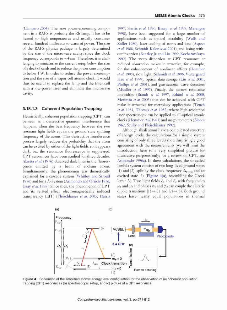
The vertical design makes it possible to fabricatelarge arrays of VCSELs, thus reducing the produc-tion costs (Figure 10). Their short cavities requireBragg mirrors of high reflectivity (R > 99 %), whichreduce the sensitivity to optical feedback. Very lowthreshold currents below 1 mA (Choquette et al. 1994,Huffaker et al. 1994, Yang et al. 1995) have beenreported, allowing small power consumption. At thesame time, VCSELs have a large tuning of their out-put frequency with temperature (�30 GHz K�1) andinjection current (�300 GHz mA), which causessome problems for clock applications and places con-straints on the current source and servo loops.
Even though laser linewidths of 3 MHz have beenreported (di Sopra et al. 1999), most commerciallyavailable VCSELs have linewidths of around50 MHz (Schmidt et al. 1996). While this can be aproblem for many laser spectroscopy applications(Affolderbach et al. 2000), it does not substantiallyaffect the CPT resonances. As mentioned in Section3.18.1.3, the linewidth of the CPT resonance depends
vol. 3, pp.571-612ms,
p-DBRActive cavity
n-DBR
p-contact
n-contact
Oxide aperture
dp-ring
dox
(a)
(b) (c)
270
μm
230 μm
Figure 10 (a) Schematics and (b) photograph of a
vertical-cavity surface-emitting laser (VCSEL). (c) Scanning
electron microscope (SEM) picture of a VCSEL mesa afteretching (before deposition of dielectrics and metal), the
mesa height is about 3mm. (Source: Avalon Photonics,
Avalon Photonics Datacom VCSELs, http://www.avap.ch;
reproduced with permission from Avalon Photonics Ltd.)
MEMS Atomic Clocks 581
on the relative phase stability between the light fields,
that is, the microwave phase, and not on the stability ofthe individual light fields (Dalton and Knight 1982).
Nevertheless, a large VCSEL linewidth can reduce
the CPT clock performance because of the large FM
noise (Kitching et al. 2001c). The FM to amplitudemodulation (AM) conversion process (Camparo
1998a) that occurs in the atoms adversely affects the
CPT signal.VCSELs have been developed for telecom applica-
tions since the 1980s (Fumio et al. 1989, Jewell et al.
1989), and reliable single-mode VCSELs have become
available at the D2 lines of Cs (852 nm). Lifetimes
beyond one million hours have been reported (Avalon
Photonics, Honeywell, Ulm Photonics, Mukoyamaet al. 2006). Recently, VCSELs at the D1 lines of Cs
(895 nm) and Rb (795 nm), and D2 lines of Rb (780 nm)
and potassium (766 nm) have been produced.Since their structure consists of more than 100
layers and their fabrication processes and designsvary from one manufacturer to another, the charac-
teristics of single-mode VCSELs vary and directly
impact the clock performance (see, e.g., Kwakernaak
et al. 2004). It is therefore critical to choose the rightVCSEL for the specific CSAC design. In order to get
Comprehensive Microsyste
high yields, MEMS clocks must conform to stringentrequirements regarding epitaxial growth accuracyand uniformity, which is much more demandingthan is typically achieved in the best semiconductorfabrication facilities (Serkland et al. 2006). Some ofthe specifications are summarized here:
� Tunable to precise atomic wavelength (preferably795 or 894 nm) at a given operating temperature,e.g., 75�C, �5�C (Serkland et al. 2006).
� Single longitudinal, transverse, and polarizationmode.
� Phase modulation index, >1.8 reachable with radiofrequency (RF) powers of �6 dBm at 3.4 GHz(Brannon et al. 2005) or 0 dBm at 4.6 GHz(Serkland et al. 2006).
� Linewidth, <100 MHz (Serkland et al. 2006).� Power consumption, <3 mW.� Optical output power, 50 mW–1 mW.
3.18.2.2.3 Vapor cells
The vapor cell can be viewed as the heart of theclock, as it contains the atoms. Besides being a con-tainer that does not react with the atoms, the cell hasto provide access to the light to and from the atoms. Itneeds to withstand elevated temperatures, should notbe magnetic, and has to be hermetically sealed. Forchip-scale vapor cells it should furthermore allow forwafer-level fabrication and filling, since fabricationcost as well as uniformity over an ensemble of cells isof concern. The interior size of the cell should be inmillimeters and the exterior volume should be assmall as possible. Finally, the geometry of the cellneeds to be considered, when integrated with the restof the physics package.
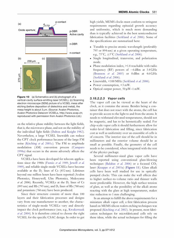
Several millimeter-sized glass vapor cells havebeen reported using conventional glass-blowingtechniques (Balabas et al. 2006) or a focused CO2
laser (Knappe et al. 2003a) (Figure 11). Glass alkalicells have been well studied for use in opticallypumped clocks. This can make the wall effects dueto higher surface-to-volume ratio and thinner wallsmore predictable. However, the high surface tensionof glass, as well as the possibility of the alkali atomsreacting with the glass at high temperatures, makessize reduction to 1 mm challenging.
In an attempt to fulfill the above requirements for aminiature alkali vapor cell, a first fabrication processbased on MEMS silicon wafers etching techniques wasproposed (Kitching et al. 2002). At present, most fabri-cation techniques for microfabricated cells rely onthese ideas, while the actual techniques for filling the
vol. 3, pp.571-612ms,
(a)
1.5 mm
(b)
Figure 11 Photographs of small vapor cells: (a) madefrom a hollow-core glass fiber with a CO2 laser; (b) made
with conventional glass-blowing techniques.
582 MEMS Atomic Clocks
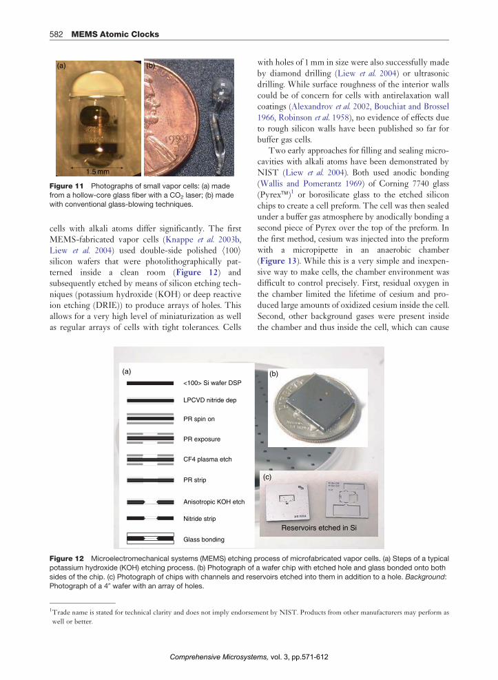
cells with alkali atoms differ significantly. The firstMEMS-fabricated vapor cells (Knappe et al. 2003b,Liew et al. 2004) used double-side polished h100isilicon wafers that were photolithographically pat-terned inside a clean room (Figure 12) andsubsequently etched by means of silicon etching tech-niques (potassium hydroxide (KOH) or deep reactiveion etching (DRIE)) to produce arrays of holes. Thisallows for a very high level of miniaturization as wellas regular arrays of cells with tight tolerances. Cells
<100> Si wafer DSP
LPCVD nitride dep
PR spin on
PR exposure
CF4 plasma etch
PR strip
Anisotropic KOH etch
Nitride strip
Glass bonding
(a)
Figure 12 Microelectromechanical systems (MEMS) etching p
potassium hydroxide (KOH) etching process. (b) Photograph of
sides of the chip. (c) Photograph of chips with channels and res
Photograph of a 40 wafer with an array of holes.
1Trade name is stated for technical clarity and does not imply endorsem
well or better.
Comprehensive Microsyste
with holes of 1 mm in size were also successfully madeby diamond drilling (Liew et al. 2004) or ultrasonicdrilling. While surface roughness of the interior wallscould be of concern for cells with antirelaxation wallcoatings (Alexandrov et al. 2002, Bouchiat and Brossel1966, Robinson et al. 1958), no evidence of effects dueto rough silicon walls have been published so far forbuffer gas cells.
Two early approaches for filling and sealing micro-cavities with alkali atoms have been demonstrated byNIST (Liew et al. 2004). Both used anodic bonding(Wallis and Pomerantz 1969) of Corning 7740 glass(Pyrex�)1 or borosilicate glass to the etched siliconchips to create a cell preform. The cell was then sealedunder a buffer gas atmosphere by anodically bonding asecond piece of Pyrex over the top of the preform. Inthe first method, cesium was injected into the preformwith a micropipette in an anaerobic chamber(Figure 13). While this is a very simple and inexpen-sive way to make cells, the chamber environment wasdifficult to control precisely. First, residual oxygen inthe chamber limited the lifetime of cesium and pro-duced large amounts of oxidized cesium inside the cell.Second, other background gases were present insidethe chamber and thus inside the cell, which can cause
Reservoirs etched in Si
(b)
(c)
rocess of microfabricated vapor cells. (a) Steps of a typical
a wafer chip with etched hole and glass bonded onto both
ervoirs etched into them in addition to a hole. Background:
ent by NIST. Products from other manufacturers may perform as
vol. 3, pp.571-612ms,

V
300°C
–
+ Cesium + buffer gas
V
–
+
(a) (b)
(c) (d)
(e)(f)
300°C
Figure 13 Schematic of cell fabrication based on silicon
etching and anodic bonding. A Si wafer (a) with holes etchedthrough it (b) is anodically bonded to a piece of glass (c). It is
then filled with alkali atoms and buffer gas (d), and a second
piece of glass is bonded on top (e) to form a robust,
hermetically sealed vapor cell (f).
SiO2
(a) (c)
(d)(b) Rb
In a glove box:Deposit wax, create divides forRb, micropipetter Rb
Wax with divides
Release wax from handle waferDice micropackets
Sandwich Rb between two waferswith wax, heat seal wax to enclose Rb
Grow SiO2
DRIE etch holes
Silicon handler
Figure 14 Process to enclose Rb in wax micropackets.
(Source: Radhakrishnan S, Lal A 2005 Alkali metal-wax
micropackets for chip-scale atomic clocks. Dig. Tech.Papers – Int. Conf. Solid State Sensors and Actuators and
Microsystems, Transducers ’05, pp. 23–6, ª 2005;
reproduced with permission from IEEE.)
MEMS Atomic Clocks 583
problems when trying to reduce the temperature coef-
ficient of the clock by using controlled mixtures of
different buffer gases (Vanier et al. 1982) (see Section
3.18.4.3 for a more detailed discussion). Very similar
filling techniques have been reported subsequently by
Kwakernaak et al. (2004) and Lutwak et al. (2005).The second filling technique was successfully
used in centimeter-sized buffer gas vapor cells before.
A stable cesium compound was deposited into the
cell and was reacted to produce pure cesium metal by
using the following process (Espe 1966):
BaN6 þ CsCl! BaClþ 3N2 þ Cs
The decomposition was initiated by heating themixture to roughly 200�C inside a UHV chamber.
The problem in a small cell arose from the difficulty
of pumping off the excess nitrogen gas formed without
having all the cesium metal leave the small cell volume
at elevated temperatures. Furthermore, the BaCl and
the free barium remained inside the cell where the
chemical solution was deposited. In bigger cells, this
can be desirable because barium can be used as a getter.
However, in small cells that are heated to higher
temperatures, the gettering rate of nitrogen by barium
can cause pressure changes in the cells that result in
frequency changes (Knappe et al. 2005a). Since the
Comprehensive Microsyste
clock frequency of cesium is extremely sensitive tothe nitrogen pressure (45� 2 Hz kPa�1; Beverini et al.
1981), the pressure has to be stable at 2� 10�3 kPa tosupport a frequency stability of 1� 10�11. When usingbarium inside small buffer gas cells, nitrogen must becompletely avoided and instead atoms such as inertgases can be used. But even then it can be difficult toensure that the chemical reaction has been completedand that no nitrogen is left inside the cell.
One advantage of chloride reduction through bar-ium is that it is relatively easy and cheap to producesmall quantities of isotopically enriched 87Rb.Usually, isotopical purity of 87Rb is preferred sothat the light is not absorbed by the 85Rb atoms(with 62% natural relative abundance), for whichthe CPT condition is not fulfilled. In order not tohave any residues inside the cell cavity, the alkaliatoms can be produced this way inside a glassampoule and evaporated into the cell cavity througha small nozzle (Knappe et al. 2005a). The cell is thenclosed after filling the chamber with the desiredbuffer gas mixture. This is a versatile technique,and the cells with Cs, 87Rb, and 85Rb and a varietyof buffer gases with pressures <1 torr to 1 atm havebeen produced this way.
Other approaches to insert the alkali atoms intoMEMS cell cavities have also been reported on sincethen. Radhakrishnan and Lal (2005) encapsulated rubi-dium in wax micropackets as shown in Figure 14. Thecell preforms were made by anodic bonding of bulk-micromachined silicon wafers to Pyrex under a xenonatmosphere. One side of the cavity array has a silicon
vol. 3, pp.571-612ms,

Anodicbonding
Anodicbonding
SiliconSilicon
(b)
(c)
(a)
NaNO3
–
+ CopperHot plate
Pyrex
Pyrex
Figure 16 Schematic of the electrolytic cell filling
process. (a) A Si wafer with a hole of 2.5 mm diameter is
anodically bonded to a Pyrex wafer with a shallow well,2.5 mm in diameter. Pieces of Cs-enriched glass (dark blue)
are melted into the well. (b) Another Pyrex wafer is
anodically bonded to the other free surface of the silicon
wafer under an argon cover gas. (c) A copper stem,containing molten NaNO3 salt in a basin at the top, is
pressed against the Pyrex below the Cs glass well. The
stem is attached to the copper base, resting on a hot plate
at a temperature of 500�C. A potential of þ700 V is appliedfor a few minutes between the molten NaNO3 anode and the
silicon cathode. (Source: Gong F, Jau Y Y, Jensen K,
Happer W 2006 Electrolytic fabrication of atomic clock cells.Rev. Sci. Instrum. 77, 076101, ª 2006; reproduced with
permission from American Institute of Physics.)
584 MEMS Atomic Clocks
nitride membrane that gets thermally bonded to thewax micropackets, as shown in Figure 15. The rubi-dium is released into the cavity by laser ablation of thesilicon nitride membrane. Rubidium absorption wasmeasured in these cells successfully, but the effect ofthe wax on the ground-state hyperfine coherence hasnot been studied yet.
A wafer-level process to make arrays of nitrogenbuffer gas cells with cesium has been developed byLiew et al. (2006a, b). Here, cesium azide (CsN3) isevaporated through an aluminum shadow mask intocell preforms made from silicon with borosilicateglass windows. The cavities are closed under vacuumby anodically bonding a wafer of borosilicate glassonto the top. The cesium azide is decomposed intocesium and nitrogen by exposing the cells to ultra-violet light. The decomposition is stopped when thenitrogen pressure reaches the desired value.
A technique demonstrated by Gong et al. (2006)uses cesium-enriched glass as a source for alkaliatoms in microfabricated cells. The glass pieces aremelted into a well on the bottom of an anodicallybonded cell preform (Figure 16). The cell is closedby anodic bonding under the desired buffer gas atmo-sphere. Finally, the cesium atoms are released fromthe glass by passing an electrolytic current throughthe glass at 500�C and 1 kV between a NaNO3 anodeand the silicon (cathode).
Pyrex(a)
(b)
(c)Si
Laser
SiLaser ablate from the pyrexside to release Rb into the cell
Rb Wax micropacketAttach Rb wax micropackets toSixNy membrane by heating towax-softening temperature
Low-stress SixNy
Form cavities in silicon waferAnodically bond to pyrex wafer,Fill the chamber with buffer gas
Figure 15 Process outline to realize Rb vapor cells using
Rb wax micropackets. (Source: Radhakrishnan S, Lal A
2005 Alkali metal-wax micropackets for chip-scale atomicclocks. Dig. Tech. Papers – Int. Conf. Solid State Sensors
and Actuators and Microsystems, Transducers ’05,
pp. 23–6, ª 2005; reproduced with permission from IEEE.)
Comprehensive Microsyste
A MEMS glass-blowing technique has beenreported by Erklund and Shkel (2006). As the sche-matic in Figure 17(a) explains, cavities are etched intoone side of a silicon wafer using DRIE. A 100-mm-thickpiece of borosilicate glass is then anodically bondedover the top of the cavities enclosing the atmosphericpressure. When the wafer is heated to 850�C, that is,above the melting point of the glass, the air pressureinside the cavities deforms the glass into sphericalshapes, as shown in Figure 17(b). Afterward, the back-side of the cavities is etched to allow for filling withalkali atoms. 87Rb cells have been made this way byusing the evaporative filling method described pre-viously and by anodically bonding a second piece ofborosilicate glass over the backside in the presence of anitrogen and xenon atmosphere.
3.18.2.2.4 OpticsEven though the actual designs of the physicspackages vary significantly, in almost all cases, thereis an optics package that controls the size, intensity,and polarization of the laser beam. Most approachesuse circular polarization by passing the beam througha low-order quarter waveplate. Neutral density (ND)filters are a simple way to attenuate the light to thedesired power of around 10 mW. At the same time,these attenuators can reduce the optical feedback
vol. 3, pp.571-612ms,

1. Pattern Si wafer with photoresist and etch (DRIE)
2. Remove photoresist and bond thin Pyrex 7740 to Si wafer
3. Heat in furnace at approx. 850°C
4. Pattern and etch (DRIE) backside
5. Fill cells and seal backside by anodic bonding
(a)
(b)
2 mm
Figure 17 (a) Wafer-level fabrication of glass-blown vapor cells. (b) Photograph of a micro glass cell on top of a silicon wafer.
(Courtesy of J. Erklund).
(a)250 mm
ND
ND
QuartzSi
Glass
Lens
VCSEL
Alumina
1.5 mm
(b)
Figure 18 Schematic (a) and photo of a chip-scale atomic
clock (CSAC) optics package.
MEMS Atomic Clocks 585
produced by light that gets reflected back into theVCSEL. Some optics packages also use antireflec-tion-coated elements. In some setups, a polarizer isinserted to filter out the undesired polarizationmodes (Gerginov 2006). While in many designs thelaser beam is collimated by a microlens, it has beenshown that this is not necessary and a diverging beamcan be used instead (Lutwak et al. 2004). Figure 18shows an example of an optics package consisting of aspacer, a ND filter, an inkjet-printed epoxy lens, anda quarter waveplate through which the beam passes.Other designs use more complicated beam paths byimplementing micromirrors in the optics package.
3.18.2.2.5 Heating
In order to achieve sufficient absorption of the laserlight over a 1 mm path length, the alkali vapor pressurehas to be increased from its room temperature. Becausemost cells contain a liquid or a solid drop of alkalimetal along with the vapor, this is usually done bysimply heating the cell. The temperature for 50%absorption of the resonant light depends also on thebuffer gas pressure, since buffer gas collisions change
Comprehensive Microsyste
the lifetime of the P states (Allard and Kielkopf 1982).For higher pressures and low laser powers, the alkalidensity has to be increased proportional to the increasein buffer gas pressure to maintain the same absorption.For a 20-kPa nitrogen cell, for example, this tempera-ture is around 75�C for cesium and 90�C for rubidium.Furthermore, it is advantageous to maintain the cellwindows at a temperature slightly higher than the bodyof the cell to minimize the quantity of the alkali atomsthat condense on the windows.
vol. 3, pp.571-612ms,

586 MEMS Atomic Clocks
Microfabricated heaters are not a new technology(Lai et al. 1995, Nguyen and Howe 1993, Ruther et al.
2004) and approaches differ significantly. To reducethe magnetic fields produced by the currents flowingthrough the resistive heaters, patterned traces areoften meandered and retraced and resistances arechosen such that only small currents flow. Tracescan also be made from transparent materials or pat-terned such that the laser beam can pass through thecenter of the cell for better uniformity of heat dis-tribution (Lutwak et al. 2004). Furthermore, thinsubstrate materials with low thermal conductivitiesare used for better thermal insulation. Substrates,heaters, and temperature sensor materials are chosento be least magnetic, e.g., platinum, glass, polyimide,indium tin oxide (ITO).
Figure 19 shows an example of microfabricatedtransparent heaters (Schwindt et al. 2006) made from
Glass
Glass
ITOInsulating layer
Epoxy
Conductiveepoxy
1.6 mm
2.3 mm
Conductiveepoxy
(a)
(b) Gold
Figure 19 (a) Photograph and (b) schematic side view oflaser-patterned indium tin oxide (ITO) heater. (Source:
Schwindt P D D, Lindseth B, Knappe S, Shah V, Kitching J
2006 A chip-scale atomic magnetometer with improvedsensitivity using the Mx technique. Appl. Phys. Lett.)
1.1
cm
(a)
Silicon bifilaheater coils
Wirebond p
Boron-dopelectrical tr
Etched cell cavity
Silicon
Figure 20 (a) Design of an advanced cell with integrated heaters
Moreland J, Knappe S, Shah V, Schwindt P, Gerginov V, Kitching J
in-situ heating for atomic-based sensors. Proc. 3rd Int. Symp. Se
Comprehensive Microsyste
ITO. The heaters are glued directly onto the cellwindows, and heat is produced when current flowsthrough the conductive ITO layers. Two glass sub-strates with patterned ITO are glued together with anonconductive epoxy to reduce the magnetic fields.The lighter color lines in the heater are where ITOhas been removed through laser patterning. After theITO patterning, gold pads are deposited for wirebonding, and a 2-mm insulating layer of benzocyclo-butene is deposited over the remaining exposed ITOso that the electrical contact between the upper andthe lower ITO layers is made only through the goldpads. The large arrows show where current entersand exits the heater. The electrically conductiveepoxy provides the connection between the upperand the lower ITO. Figure 20 shows a vapor cellwith integrated heaters made from boron-dopedsilicon. The doped bifilar traces are bulk-microma-chined into the silicon cell preform with a high aspectratio (Liew et al. 2005, 2006b).
3.18.2.2.6 Magnetic field control
Most CSACs are operated on the mF¼ 0$mF¼ 0hyperfine transition, to be insensitive to magnetic fieldsin first order. The magnetic field shifts the neighboringZeeman sublevels apart with �7 kHzmT�1 for 78Rband �3.5 kHzmT�1 for Cs. Therefore, a field of a fewmicrotesla in strength is sufficient to separate theneighboring CPT resonances of a few kilohertz line-width. In order to couple the two 0–0 hyperfinecomponents with circularly polarized light, a longitu-dinal magnetic field is required.
Until now, not much has been published about howto precisely control the magnetic field in the vicinity ofthe tiny vapor cell. Nevertheless, magnetic fieldstrength, homogeneity, and direction can be of concern.The amplitude of the CPT 0–0 resonance is propor-tional to cos2(�), where � is the angle between the
Cellcavity
(b)
r
ads
ed aces
Sili
con
heat
ers
. (b) Photograph of closeup of the cell cavity. (Source: Liew L,
, Hollberg L 2005 Microfabricated alkali atom vapor cells with
nsor Science, Juelich, Germany, pp. 181–3.)
vol. 3, pp.571-612ms,

MEMS Atomic Clocks 587
direction of laser propagation and the magnetic field(Wynands and Nagel 1999). Also, because fairly highbuffer gas pressures are used in most cells, the atomscan be considered stationary and sample the magneticfield at their location. The CPT resonance is then aconvolution of all atoms interrogated and thereforebroadens with magnetic field gradients across the cell.But again, if the 0–0 transition is used in buffer gas cells,this effect is reduced because the 0–0 resonance shiftswith the magnetic field in second order only. It couldbe further reduced by using antirelaxation wall-coatedcells (Robinson et al. 1958), where motional narrowing(Bloembergen et al. 1948, Kleppner et al. 1962) wouldsuppress the gradient-induced broadening. Finally, theCPT 0–0 resonance frequency shifts with the totalmagnetic field at 57.5 mHzmT�2 for cesium and42.7 mHzmT�2 for 87Rb (see, e.g., Steck 1998, 2001,and references therein).
The externally applied offset field should thereforebe made as small as possible to reduce frequency shiftsand broadening due to ambient field changes (e.g.,through heater currents), but big enough to lift theZeeman degeneracy beyond the CPT linewidth andto ensure that ambient fields are not rotating the direc-tion of the total field too much (e.g., earth’s magneticfield). The external offset field is applied through eithermagnetic coils or permanent magnets. The lattermethod has the advantage of reducing the power con-sumption of the CSAC and the residual magnetic fieldsbecause the heater supply leads are not present. Thedisadvantage is that the CSAC frequency cannot betuned through the C-field (as is most commonly usedin Rb vapor clocks). The physics package is usuallyshielded from external magnetic fields, for example, theearth’s magnetic field, by at least one layer of materialwith high permeability. It has been shown that shield-ing factors of around 1000 for one layer and greaterthan 4� 106 (Hodby 2006) for three-layer shields ofseveral millimeters in size can be reached.
3.18.2.3 Local Oscillator
3.18.2.3.1 IntroductionMost of the CSACs described so far are passive atomicclocks (see Section 3.18.2.1). The clock frequency isproduced by a LO, which is locked to the atomicCPT resonance with a loop bandwidth BWlock. Theclock frequency is determined by the atomic ground-state hyperfine frequency, i.e., 6.834 GHz for 87Rb or9.192 GHz for 133Cs. Using CPT interrogation, a modu-lation of the VCSEL at half these frequencies ispossible. Many applications, however, require a clock
Comprehensive Microsyste
with an output frequency of 10 MHz, and frequenciesup to 100 MHz can probably be used. Therefore,either the LO frequency has to be divided for theoutput or a low-frequency LO (10 MHz, for example)should be multiplied for VCSEL modulation. Forreaching the goal of 30 mW total power consumptionfor the CSAC, the output frequency should mostlikely be the specific gigahertz frequency, determinedby the atoms. In the following, we will mostly focus onLOs at microwave frequencies, which are developed forthe chip-scale clocks. The list presented here is notcomplete but is rather a condensed overview.
As a passive standard, the CSAC frequency stabi-lity at times shorter than (BWlock)�1 is determinedmostly by the phase noise of the LO. To reach a clockfrequency stability of 1� 10�11 at 1 h of integration,the single-sideband phase noise power spectral den-sity of the LO needs to be between �25 dBc Hz�1 at100 Hz offset (Brannon et al. 2005, Kitching 2003) and�43 dBc Hz�1 at 300 Hz offset (Romisch and Lutwak2006) from the carrier. The required output powerdepends largely on the modulation efficiency of andthe coupling efficiency to the VCSEL. It has beenshown that for some VCSELs <�6 dBm outputpower at 3.4 GHz can be sufficient to transfer 60%of the light power into the desired first-order side-bands (Brannon et al. 2006b). At 4.6 GHz, therequirement was set to 0 dBm (Romisch andLutwak 2006). In order to reach the goal of totalpower of 30 mW for the CSAC, it would be desirableif the DC power consumption of the LO was wellbelow 10 mW and the footprint below 1 cm2.
A significant concern is the thermal frequency driftof the voltage-controlled oscillator (VCO). Since it ismost likely not actively temperature-stabilized, itsresonance frequency must not drift out of the tuningrange provided by the servo when the ambient tem-perature varies over the entire operating range of theclock. A maximal thermal frequency shift of around�10 ppm K�1was therefore a goal with a tuning rangeof a few megahertz. At the same time, the tuning rangeof the VCO should be small for good resolution andfrequency stability, but should be large enough tocompensate for manufacturing tolerances. Finally, asupply voltage below 3.5 V is desired and all thecomponents should be of low cost.
The best available oscillators at gigahertz frequen-cies are dielectric resonator oscillators (DROs) withQ factors of several thousand (Pozar 2001) and even100 000 for cryogenically cooled sapphire devices(Ivanov and Tobar 2006, Ivanov et al. 1998). Buttheir size, weight, and power make them unsuitable
vol. 3, pp.571-612ms,
(a)
(b) (c)
3.4 GHzcoupled
DC bias
V tune 3.4 GHzout
588 MEMS Atomic Clocks
for MEMS clocks. Crystal oscillators can be very
good with similar Qs in the frequency range of up
to hundreds of megahertz (Vig 1992). Oven-con-trolled devices (OCXOs) have very good stability,
but require several hundred milliwatts of power, but
TCXOs or microprocessor-controlled (MCXO)
crystal oscillators can operate on a few milliwatts.
Nevertheless, multiplying their frequencies into the
gigahertz region may require too much power for
CSACs. Therefore, considerable research is done onalternative approaches of small, low-power LOs at
gigahertz frequencies.
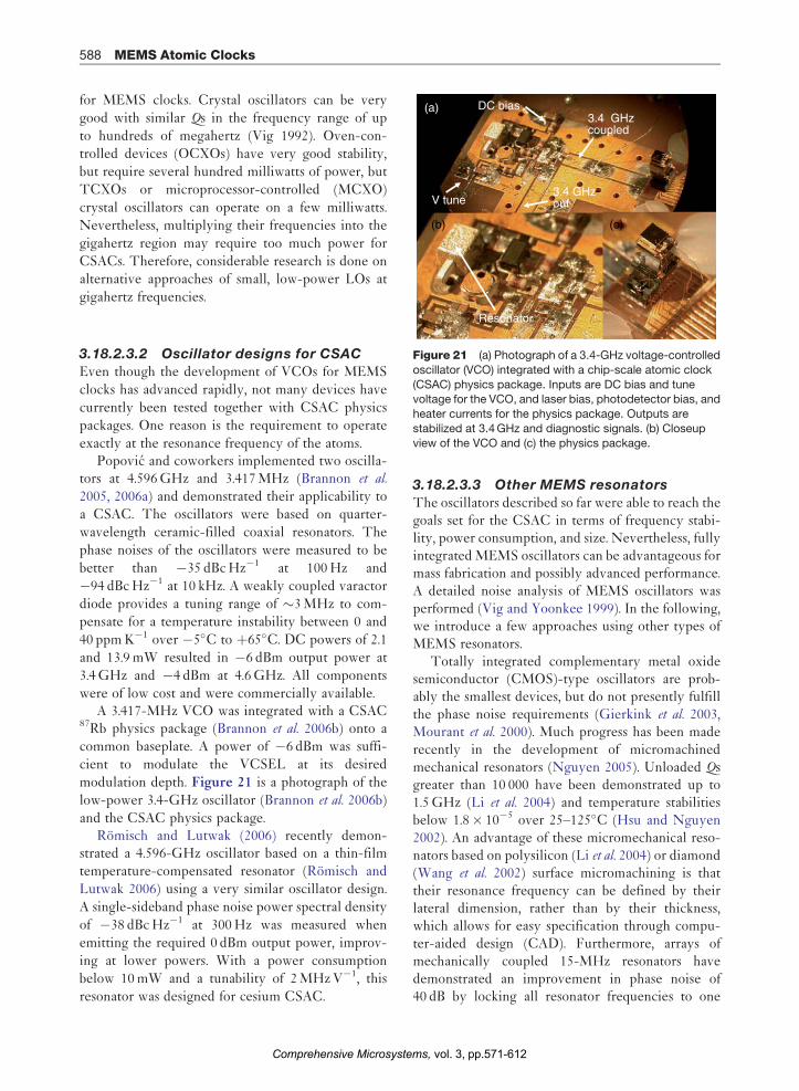
Resonator
Figure 21 (a) Photograph of a 3.4-GHz voltage-controlled
oscillator (VCO) integrated with a chip-scale atomic clock
(CSAC) physics package. Inputs are DC bias and tunevoltage for the VCO, and laser bias, photodetector bias, and
heater currents for the physics package. Outputs are
stabilized at 3.4 GHz and diagnostic signals. (b) Closeup
view of the VCO and (c) the physics package.
3.18.2.3.2 Oscillator designs for CSACEven though the development of VCOs for MEMS
clocks has advanced rapidly, not many devices have
currently been tested together with CSAC physics
packages. One reason is the requirement to operate
exactly at the resonance frequency of the atoms.Popovic and coworkers implemented two oscilla-
tors at 4.596 GHz and 3.417 MHz (Brannon et al.
2005, 2006a) and demonstrated their applicability to
a CSAC. The oscillators were based on quarter-
wavelength ceramic-filled coaxial resonators. The
phase noises of the oscillators were measured to be
better than �35 dBc Hz�1 at 100 Hz and
�94 dBc Hz�1 at 10 kHz. A weakly coupled varactor
diode provides a tuning range of �3 MHz to com-pensate for a temperature instability between 0 and
40 ppm K�1 over �5�C to þ65�C. DC powers of 2.1
and 13.9 mW resulted in �6 dBm output power at
3.4 GHz and �4 dBm at 4.6 GHz. All components
were of low cost and were commercially available.A 3.417-MHz VCO was integrated with a CSAC
87Rb physics package (Brannon et al. 2006b) onto acommon baseplate. A power of �6 dBm was suffi-
cient to modulate the VCSEL at its desired
modulation depth. Figure 21 is a photograph of the
low-power 3.4-GHz oscillator (Brannon et al. 2006b)
and the CSAC physics package.Romisch and Lutwak (2006) recently demon-
strated a 4.596-GHz oscillator based on a thin-filmtemperature-compensated resonator (Romisch and
Lutwak 2006) using a very similar oscillator design.
A single-sideband phase noise power spectral density
of �38 dBc Hz�1 at 300 Hz was measured when
emitting the required 0 dBm output power, improv-
ing at lower powers. With a power consumptionbelow 10 mW and a tunability of 2 MHz V�1, this
resonator was designed for cesium CSAC.
Comprehensive Microsyste
3.18.2.3.3 Other MEMS resonators
The oscillators described so far were able to reach thegoals set for the CSAC in terms of frequency stabi-lity, power consumption, and size. Nevertheless, fullyintegrated MEMS oscillators can be advantageous formass fabrication and possibly advanced performance.A detailed noise analysis of MEMS oscillators wasperformed (Vig and Yoonkee 1999). In the following,we introduce a few approaches using other types ofMEMS resonators.
Totally integrated complementary metal oxidesemiconductor (CMOS)-type oscillators are prob-ably the smallest devices, but do not presently fulfillthe phase noise requirements (Gierkink et al. 2003,Mourant et al. 2000). Much progress has been maderecently in the development of micromachinedmechanical resonators (Nguyen 2005). Unloaded Qsgreater than 10 000 have been demonstrated up to1.5 GHz (Li et al. 2004) and temperature stabilitiesbelow 1.8� 10�5 over 25–125�C (Hsu and Nguyen2002). An advantage of these micromechanical reso-nators based on polysilicon (Li et al. 2004) or diamond(Wang et al. 2002) surface micromachining is thattheir resonance frequency can be defined by theirlateral dimension, rather than by their thickness,which allows for easy specification through compu-ter-aided design (CAD). Furthermore, arrays ofmechanically coupled 15-MHz resonators havedemonstrated an improvement in phase noise of40 dB by locking all resonator frequencies to one
vol. 3, pp.571-612ms,

MEMS Atomic Clocks 589
mode (Lee and Nguyen 2004). Nevertheless, nooscillator using one of these micromachined resona-tor tank has been demonstrated in the gigahertzregion as at the time of this writing (2006).
MEMS techniques lend themselves to the makingof gigahertz oscillators for CSACs, as small size allowsfor faster speed, lower power consumption, and lowercost. In the case of quartz resonators, MEMS fabrica-tion enabled quartz on-chip resonators at 900 MHzwith Qs greater than 10 000 and strong third overtonemodes above 2.5 GHz and Qs greater than 7500(Kubena et al. 2005, Stratton et al. 2004). Temperature
QUARTZ
(a)
(b)
1. Starting materials
2. Etch cavities in Si
4. Bond quartz to Si handle
5. Thin quartz to <10 μm
3. Pattern and metallize top electrodes on quartz
6. Pattern and metallize via holes in quartz
QUARTZ
QUARTZ
SILICON HANDLE
SILICON HANDLE
SILICON HANDLE
SILICON HANDLE
HOST SUBSTRATE
SILICON HANDLE
Figure 22 (a) Fabric flow for a microelectromechanical system
microscope (SEM) photograph of a completed ultrahigh frequenKubena R L, Stratton F P, Chang D T, Joyce R J, Hsu T Y, Lim M
filters for on-chip integration. Proceedings of the 2005 IEEE Inte
pp. 122–27, ª 2005; reproduced with permission from IEEE.)
Comprehensive Microsyste
coefficients around �5 ppm K�1 have been measuredin shear strip designs. The fabrication process and ascanning electron microscope (SEM) photograph of acomplete ultrahigh frequency (UHF) quartz resonatorare shown in Figure 22 as an example.
Other interesting candidates include thin-film bulkacoustic resonators (FBAR) and high-tone bulk acous-tic resonators (HBAR). Frequency-tunable FBARoscillators at 2 GHz showed a phase noise of�112 dBc Hz�1 at 10 kHz and an unloaded Q betterthan 500 (Khanna et al. 2003). With a supply voltage of3.3 V, it uses 115 mW of power and had a tuning
8. Pattern and etch quartz resonator
10. Pattern and metallize bond pads
11. Bond Si/quartz to host substrate
12. Remove Si handle
0400-00-013
9. Etch protrusion in host substrate
7. Pattern and metallize bottom electrodes on quartz
SILICON HANDLE
SILICON HANDLE
SILICON HANDLE
HOST SUBSTRATE
HOST SUBSTRATE
HOST SUBSTRATE
HOST SUBSTRATE
s (MEMS)-based quartz resonator. (b) Scanning electron
cy (UHF) resonator with 2-mm quartz thickness. (Source:K, M’closkey R T 2005 MEMS-based quartz oscillators and
rnational Frequency Control Symposium and Exposition,
vol. 3, pp.571-612ms,

200 μm
(a) Al
ZnOSiO2
XeF2 XeF2
Si
(b)
Figure 23 (a) Cross-section schematic of an Al/ZnO/Al/
SiO2 film bulk acoustic resonator (FBAR) and (b) photograph
of the fabricated FBAR. (Source: Zhang H, Kim J, Pang W,Yu H, Kim E S 2005 5 GHz low-phase-noise oscillator based
on FBAR with low TCF. The 13th Int. Conf. Solid-State
Sensors, Actuators and Microsystems, Dig. Tech. Papers
(Transducers ’05), pp. 1100–1, ª 2005; reproduced withpermission from IEEE.)
Physics package
Microprocessor
1.55″
1.39
″Figure 24 Prototype printed circuit (PC) board for aminiature atomic clock. (Source: Lutwak R, Vlitas P,
Varghese M, Mescher M, Serkland D K, Peake G M 2005 The
MAC – A miniature atomic clock. Joint Meeting of the IEEE
International Frequency Control Symposium and the PreciseTime and Time Interval (PTTI) Systems and Applications
Meeting, Vancouver, BC, Canada, pp. 752–7.)
590 MEMS Atomic Clocks
sensitivity of 180–370 kHz V�1 (0–10 V tuning range).FBAR resonators generally have temperature stabilitiesof 20–30 ppm K�1. Pang et al. (2005) have reduced thetemperature coefficient of a tunable FBAR resonator at2.8 GHz by 40 ppm K�1 by integrating a microma-chined air-gap capacitor and Zhang et al. (2005)demonstrated a temperature stability of �8.7 ppm K�1
with a 5-GHz CMOS-compatible device. Care has tobe taken in the design of FBAR oscillators to satisfy theresonance condition for the desired mode only, as theycan have closely spaced series and parallel resonances.A schematic and a photograph of a 5-GHz FBARoscillator are shown in Figure 23.
Resonators can be scaled even smaller withnanoelectromechanical systems (NEMS) to allowfor Q factors in the range of 1000–100 000 with verylow power consumption. Double-clamped beamsmade from SiC reach microwave frequencies(Ekinci and Roukes 2005).
3.18.2.4 Control Electronics
Besides the physics package and the LO, the CSACneeds miniaturized control electronics for operatingthe clock by providing the supply currents and vol-tages for the individual components and forcontrolling at least four servo loops for laser andcell temperature, laser frequency, and LO frequency.Sometimes, laser and cell are maintained at the sametemperature and the two servos can be combined.
To reach the goal of 1 cm3 total volume for theCSAC, an application-specific integrated circuit(ASIC) will most likely be required. Until now, pro-totypes of 10 cm3 have been demonstrated (Gerginovet al. 2005, Lutwak et al. 2005) with control electronics
Comprehensive Microsyste
based on digital microprocessors. Figure 24, for exam-
ple, shows a printed circuit (PC) board of footprint
14 cm2 containing all the control electronics necessary
to run a CSAC. As shown in the block diagram in
Figure 25, the analog signals from the CSAC are
converted into digital signals and processed by the
microprocessor. The output is converted into analog
signals again, which in turn drive the CSAC.The temperatures are usually measured by ther-
mistor temperature sensors. A proportional integrator
(PI) servo is programmed into the microprocessor chip
and the single-sided (heating only) output controls the
heater currents. For low power consumption, the cell
and the laser are operated above the maximum ambi-
ent temperatures, so that no cooling is required.Since the laser and the LO have to be locked to
the center of the optical and microwave resonance
lines, respectively, phase-sensitive detection is
implemented for these two servos. The laser current
and the LO tuning voltage are modulated at a low
frequency (500 Hz–30 kHz), and the photodetector
voltage is demodulated at this frequency. To prevent
cross-talk between the two loops, the two modulation
frequencies are usually chosen to be different by an
order of magnitude and the demodulation filters
have to be tuned accordingly. The phase of the
vol. 3, pp.571-612ms,

Signalconditioning
+2.8 V Bias
C-fieldbias Temperature
controller
PhysicsΣ
Cs
DAC
D/A Coa
rse
tune
VC
SE
L fin
e tu
ne
TT
L M
OD
PLL
OCXO tuning
20 MHzTCXO
20 MHzClock output
4596 MHzVCO
4.6 GHz
ACMOSBUFFER
Loopfilter
Err inMod inD/A
D/A
D/A
A /D Microprocessorcore
IRQ
Timer
CLK
Microcontroller
Bit
Figure 25 Block diagram of a miniature atomic clock. (Source: Lutwak R, Vlitas P, Varghese M, Mescher M, Serkland D K,Peake G M 2005 The MAC – A miniature atomic clock. Joint Meeting of the IEEE International Frequency Control Symposium and
the Precise Time and Time Interval (PTTI) Systems and Applications Meeting, Vancouver, BC, Canada, pp. 752–7.)
MEMS Atomic Clocks 591
demodulation has to be chosen precisely for bestperformance. Due to the high tunability of VCO(�2 MHz V�1) and VCSEL (�300 GHz mA�1),highly stable supply voltage and current are needed.In order to run the CSAC off a common voltagesupply, for example, two AA batteries (3 V), heaterresistances and current supplies have to be designedfor minimum power consumption at this voltage.
3.18.2.5 Packaging
When power consumption is the concern, packaging,especially for the physics package, becomes a criticalissue. Since laser and cell are heated above the ambi-ent temperature, that is, to at least 75�C for manyapplications, thermal management and control needto be addressed. Without this control, physicspackages will require 100–250 mW just to heat thesmall vapor cell and tiny laser die (Kitching et al.
2004). Most of the heating power is then lost ther-mally through conduction and convection.
Conduction can be tremendously reduced byincreasing the thermal resistance between the physicspackage and the environment. Figure 26 shows aCSAC physics package that consumes <10 mW of
Comprehensive Microsyste
power at an ambient temperature of 25�C to heat the
cell (Lutwak et al. 2004). The heat conduction has been
reduced to 13mW K�1 by suspending the physics
package on a thin web of strained polyimide support
tethers. Electrically conductive leads composed of gold
and platinum are deposited on top with a titanium
adhesive layer to supply the heating current.Convection is minimized by vacuum packaging.
Immersion has been suggested as a lower-cost alter-
native in some materials of low thermal conductivity. A
different approach for a MEMS clock physics package
has been proposed by Youngner et al. (2005), and also
includes a thermal suspension system (Figure 27).One of the major challenges in the thermal man-
agement is the requirement to maintain temperature
control better than 100 mK over a wide range of
ambient temperatures (�40 to þ70�C) with a small
power budget. This is further complicated by the
heat dissipated by the VCSEL (Kitching et al. 2004).
One solution can be a MEMS thermal conduction
switch that can change the thermal resistance
between the physics package and the environment
(Laws et al. 2005). A schematic of a physics package
that implements such a thermal switch is shown in
Figure 28.
vol. 3, pp.571-612ms,

Heater / sensor
Resonancecell
Upper suspension
Lower suspension
Spacer
VCSEL / detector
(a)
(b)
Figure 26 (a) Cutaway view and (b) photograph of a low-power chip-scale atomic clock (CSAC) physics package. (Source:
Lutwak R, Deng J, Riley W, Varghese M, Leblanc J, Tepolt G, M.Mescher, Serkland D K, Geib K M, Peake G M 2004 The chip-
scale atomic clock – Low-power physics package. 36th Annual Precise Time and Time Interval (PTTI) Meeting, Washington,DC, USA, pp. 1–14. Honeywell permission.)
30
2234
30
32 24 1610
1220
3028
26
36 3018
14
Figure 27 Schematic of a chip-scale atomic clock (CSAC)physics package (10) design including: substrate (12), light
source (14), light detector (16), grooves (18, 20), optical
processors (22, 24), cavity (26), vapor cell (28, 32, 44),
bridge (30), and heater (36). (Source: Youngner D W, Detry JF, Zook J D 2005 MEMS frequency standard for devices
such as atomic clocks. US PTO 6 900 702 B2.)
592 MEMS Atomic Clocks
3.18.3 Performance
3.18.3.1 Introduction
The long-term goal for most CSAC projects, set byDARPA, is to reach a frequency instability below 10�11
at 1 h of integration in a 1 cm3 package consuming
Comprehensive Microsyste
<30 mW of power. Therefore, most CSACs havebeen characterized mostly by these three specifications:frequency stability at times <1 h, size, and power con-sumption. Nevertheless, for many applications, otherspecifications, such as frequency stability at timeslonger than a week, accuracy, acceleration sensitivity,magnetic field sensitivity, lifetime, no unlocks for longdurations, might be at least as important. At the sametime, which specifications will be set for the CSAC willstrongly depend on the application. In the followingsections, we nevertheless focus mostly on the threespecifications set by DARPA.
3.18.3.2 Frequency Stability
3.18.3.2.1 Introduction
Atomic clocks are often characterized by their Allandeviation �y(� ) (for a review, see Allan 1987), whichis a measure of the fractional frequency stability asa function of averaging time � . Over short averagingtimes, the stability of many atomic clocks is charac-terized by white frequency noise. For this type ofnoise, the Allan deviation decreases as ��1/2
(Figure 29, light gray dots) and can be expressed in
vol. 3, pp.571-612ms,

Cs cell with magneticcoil and local heater(70°C) 0.5 to 10.5 mW VCSEL with
local heater(70°C) 4.5 to
14.5 mW
Ambient temperature: –40 to 50°C variation
Thermal conduction switch and ball or pin grid arrayAmbient Temperature = –40°C, Total Power = 30 mWAmbient Temperature = 50°C, Total Power = 9.5 mW
Lockingelectronics
5 mW
Figure 28 Illustration of heat transfer path through a chip-scale atomic clock (CSAC) design using a thermal conduction
switch to reduce overall power consumption. Heat rates are estimated to meet clock power requirements of <30 mW.
Radiation and conduction/convection are ignored. (Courtesy of V. Bright.)
10–2
10–10
Averaging time, τ (s)
Free-running oscillator
Atomic stability
Overall stability
Long-term drift
Alla
n de
viat
ion,
σy (
τ)
10–1 100 101 102 103 104 105
10–9
10–8
Figure 29 Fractional frequency stability: free-running
oscillator (dashed green line), supported by the atoms
(dashed black line), when locked to the atomic resonance.The atomic stability here is determined by white frequency
noise (light gray dots), flicker noise floor (dashed blue dots),
and frequency drift (orange dashes).
MEMS Atomic Clocks 593
terms of signal-to-noise ratio SCPT/N and resonancequality factor Q (Vanier 2001)
�yð�Þ ¼
QSCPT=N
1ffiffiffi
�p ½4�
Here, Q¼ v0/�vCPT is defined as the ratio ofresonance frequency over linewidth and is a
Comprehensive Microsyste
parameter of the order of unity related to the methodof interrogation. It is desirable to have a high signal-to-noise ratio and a narrow linewidth in order toreach good frequency stability. The fractional fre-quency stability of these clocks improves overmeasurement time until it reaches the flicker noisefloor, �y(�) _ const (Figure 29, blue dashes), or untilthe frequency starts drifting, �y(�) _ � (dashedorange dots). These drifts are usually caused byenvironmental variations that change the clockfrequency over time. A typical Allan deviation deter-mined by the atoms is shown in Figure 29 (blackdashes). In a passive CPT clock, an LO generates asignal close to the clock frequency. The physicspackage uses this signal as its input to create an out-put signal that carries information about thefrequency difference between the LO frequencyand the atomic frequency. This information canthen be used to tune the LO frequency so that italways coincides with the one of the atoms (for areview on CPT clocks, see, e.g., Vanier 2005). Thus,the stability of the clock is determined by the LOstability at times shorter than the inverse loop band-width, and by the atoms at longer times (Figure 29,red line).
For a CSAC, the frequency stability can be pre-dicted in the photon shot-noise limit to be on theorder of �2� 10�13/�1/2 for a 1-mm3 cell and
vol. 3, pp.571-612ms,

10–9
τ (s)
Alla
n de
viat
ion,
σy
(τ)
10–10
10–11
10–12
100 101 102 103 104 105
Figure 30 Fractional frequency stability as a function of
averaging time for a Cs D2 chip-scale atomic clock (CSAC)
physics package (black squares), 87Rb D1 CSAC physicspackage (red dots), CSAC physics package with integrated
local oscillator (LO) (blue triangles), and 1-mm3 87Rb vapor
cell (orange stars).
594 MEMS Atomic Clocks
typical experimental parameters (Vanier et al. 2003d).Unfortunately, in an experimental setup, this stabilityhas not been reached, since other noise sources aredominant and the signals are small. For VCSELs,laser amplitude noise and laser frequency noise playa major role. Frequency noise gets converted intoamplitude fluctuations through the atomic reso-nances (Camparo and Buell 1997, Coffer et al. 2002).In most CSACs, the VCSEL is locked to the center ofa resonance, so that this effect is drastically reducedin comparison to when locked to the side of theresonance (Kitching et al. 2001b), but it neverthelessremains significant. Here it can be advantageous touse a high buffer gas pressure where the optical linesare very broad and have a shallow FM–AM conver-sion slope (Camparo 1998a). Furthermore, in someVCSELs, mode-competition noise (Kaiser et al. 2002,Mukaihara et al. 1995b) between different polariza-tion modes causes large contributions to the noise onthe detector, especially when transformed intoamplitude noise by a polarizer. All of these noisesources reduce the frequency stability, so that thebest short-term stability reported to date in a CSACphysics package is 4� 10�11/�1/2 in a 1-mm3 cell(Knappe et al. 2005b).
Besides the effects that limit the short-term stabi-lity of the CSAC, frequency shifts and line shapeasymmetries can cause major problems at longeraveraging times. They can result from magneticfields, buffer gas pressure, temperature, light shifts,acceleration, or RF power. It is therefore critical tocontrol these parameters carefully or to find a mea-surement scheme that reduces the frequencysensitivity to changes in these parameters.
While for many primary frequency standards theabsolute clock frequency is critical (Quinn 2005), formost applications of chip-scale clocks this value is ofminor interest, as long as it can be calibrated.Nevertheless, it is of great importance that theclock frequency does not change over time, i.e., itneeds good stability, but not necessarily goodaccuracy.
3.18.3.2.2 Short-term frequency stability
The first CSAC physics package demonstrated usedthe D2 line of cesium (Knappe et al. 2004b). Its short-term frequency stability of 6� 10�10/�1/2 was lim-ited by a CPT resonance contrast of 0.9% and a CPTlinewidth of 7 kHz. The package had a volume of9.5 mm3 and required 75 mW of power at an externalbaseplate temperature of 46�C. The power budgetdid not include heating of the laser. A plot of the
Comprehensive Microsyste
Allan deviation for this CSAC physics package is
shown in Figure 30 (black squares).It has been shown for cesium (Lutwak et al. 2003)
as well as for rubidium (Stahler et al. 2002) that the
CPT resonance contrast is much higher on the D1
line than on the D2 line. The first CSAC physics
package using the D1 line of 87Rb was demonstrated
shortly after (Knappe et al. 2005b). The short-term
frequency instability was 4� 10�11/�1/2, the best
short-term frequency instability reported so far for
this simplest type of CPT CSAC with a 1-mm3 vapor
cell. A plot of the Allan deviation can be found in
Figure 30 (red dots). The improvement can be
attributed to a higher CPT resonance contrast of
4.6% as well as to fewer Zeeman sublevels in 87Rb
when compared to Cs. Finally, a CSAC physics
package using the D1 line of cesium has also been
presented with a short-term frequency instability of
1.4� 10�10/�1/2 (Lutwak et al. 2005).When the physics package is integrated with a min-
iature LO, the performance of the CSAC can change
dramatically. In order to reach large tuning ranges, the
tunability of the LOs often needs to be around
1 MHz V�1, making them very sensitive to voltage
fluctuations on the tuning input. Also, most small
low-power LOs have phase noise around �40 dBc at
100 Hz at best, which puts tight constraints on the
control system. Nevertheless, short-term stabilities of
2.4� 10�10/�1/2 have been demonstrated with an inte-
grated low-power LO physics package design (Brannon
vol. 3, pp.571-612ms,

MEMS Atomic Clocks 595
et al. 2006b) (Figure 30, blue triangles). Disciplining theVCO by the use of small control electronics can bechallenging, as higher servo bandwidths are desiredwhen compared to oscillators with better phase noise.This is worsened by the fact that several servo loopshave to be controlled simultaneously. It has been shownthat an integrated CSAC (matchbox size) can never-theless support a fractional frequency stability of6� 10�10/�1/2 (Lutwak et al. 2005).
3.18.3.2.3 Long-term frequency stabilityUntil now, we have discussed only frequency stabi-lity for integration times <100 s. Figure 30 showsthat frequency drifts determine the stability of theseCSACs at integration times >100–1000 s. Most driftis directly or indirectly caused by temperature fluc-tuations. The stabilities presented here weremeasured in a laboratory environment. It has beenshown that under such conditions, MEMS cells cansupport frequency stabilities below 1� 10�11 at 1 hand below 1� 10�10 at one day (Knappe et al. 2005a)(see orange stars in Figure 30). Nevertheless, it canbe expected that in a real-world environment, thefrequency stabilities of these CSACs will degradeseverely if the shifts are not addressed. In the follow-ing, we discuss different parameters that influencethe long-term stability.
3.18.3.2.3.(i) Buffer gas pressure As describedin Section 3.18.1.4, a buffer gas is used to narrow theCPT linewidth. At the same time it shifts the hyper-fine frequency. This shift is temperature-dependent.A standard way to reduce the temperature coefficientof the clock frequency in commercial opticallypumped devices is to use combinations of buffergases that shift in opposite directions (Arditi andCarver 1961, Vanier et al. 1982). The same techniqueworks well for CPT clocks (Knappe et al. 2001).However, in small devices, the residual temperaturecoefficient is proportional to the total buffer gaspressure. Because the pressure in most approachesis nearly an order of magnitude higher than incentimeter-sized devices, coefficients worsen accord-ingly. Furthermore, the buffer gas combinations areharder to control in microfabricated cells, becausethe anodic bonding process with its high tempera-tures can create residual gases inside the cell.Therefore, the cell temperature has to be stabilizedprecisely. It has been shown, however, that the tem-perature stability of the cell (as well as the VCSEL)can be improved when direct absorption signals fromthe atoms are used to determine the temperatures,
Comprehensive Microsyste
instead of temperature sensors in the vicinity of thecell (or VCSEL) (Gerginov et al. 2006b).
3.18.3.2.3.(ii) Light shifts Compared to opti-cally pumped clocks, light shifts can be reduced inCPT, because of the ability to create a more sym-metric system (Levi et al. 2000, Orriols 1979, Vanieret al. 1998). Nevertheless, the frequency stability ofmost CSACs is still limited by light shifts at longaveraging periods.
VCSELs have frequency tunabilities of roughly300 GHz K�1 (see Section 3.18.3.2.3). Therefore, itis essential to stabilize their temperatures precisely.This is usually done with small temperature sensors,e.g., thermistors close to the VCSEL die. When tem-perature gradients between the sensor and the diechange the VCSEL junction temperature, for exam-ple, due to ambient temperature fluctuations, itsoutput frequency changes. The frequency servothen changes the DC current of VCSEL to pull itback onto resonance, but the output power as well asthe VCSEL impedance, that is, modulation index ofthe light field, is usually different (Gerginov et al.
2006b). This in turn generally changes the clockfrequency through altered light shifts (Arditi andCarver 1961, Barrat and Cohen-Tannoudji 1961,Mathur et al. 1968). It has been shown in a large cell(Levi et al. 2000, Vanier et al. 1999, Zhu and Cutler2000, 2001) as well as in a CSAC (Gerginov et al.
2006b) that when the right RF modulation index ischosen, the total light shift from the laser carrier andall other sidebands vanishes. A similar technique hasbeen implemented in a microwave clock as well(Affolderbach et al. 2006). Furthermore, an additionalservo loop can be used to lock the RF power tothis point, where no light shifts are present (Shahet al. 2006a).
3.18.3.2.3.(iii) Other frequency shifts The fieldof MEMS clocks is very young when compared tothat of lamp-pumped Rb standards. The use of newmaterials and components raises many uncertaintiesonto the performance of these new devices. Carefulcharacterization and engineering over the comingyears will be required to turn the current prototypesinto reliable off-the shelf devices. In the following, afew of these parameters are summarized.
An important frequency shift is the RF outputpower of the LO. In an in-field environment wheretemperatures and coupling to metal objects can changedramatically, the RF power of the VCO is difficult tocontrol. The clock frequency depends critically on the
vol. 3, pp.571-612ms,

(a)
596 MEMS Atomic Clocks
power distributed over all modulation sidebandsthrough light shifts. The modulation index thereforeneeds to be stabilized. Two methods have beendemonstrated to do this. In a CSAC, the RF powercan be locked to the point where the power in thefirst-order sidebands is maximized (Gerginov et al.
2006b). In a table-top CPT setup, the RF power islocked to the point where the total light shift vanishes(Shah et al. 2006a). Furthermore, the slow modulationof the LO frequency used for phase-sensitive detectionof the CPT resonance can lead to shifts in the clockfrequency (Phillips et al. 2006).
As mentioned in Section 3.18.2.2.6, the clock fre-quency is shifted as a function of total magnetic field.At the time of writing (2006), no measurements thatcharacterize the residual shifts that occur after packa-ging and shielding have been published.
Since MEMS clocks are supposed to work inportable devices, acceleration insensitivity is ofimportance, and CSACs have not yet been character-ized in this way. Nevertheless, two LOs have beenspecified with 0.2–0.3 ppm g�1 at 10 Hz (Brannonet al. 2006b) for these clocks.
Furthermore, in optically pumped clocks withtheir glass-blown vapor cells, diffusion of gases suchas helium through the glass walls can cause problems(Bloch et al. 2000, Camparo et al. 2005). Chip-scalecells have not been characterized in this respect. Butthin glass windows and new bonding mechanismscan be of concern. And finally, the reliability of theVCSELs with unknown behaviors in CSACs dueto aging, sparks, radiation, etc., is yet to be deter-mined. Nevertheless, initial performance results areencouraging, given the very short development timeand the lack of any serious engineering.
Divider
3.417GHz
PLL TCXO
10MHz
Computer interface÷n
(b)
+ 3kHz
23 m
m
41 mm
Figure 31 Photograph (a) and schematic (b) of a frequencydivider for chip-scale atomic clock (CSAC). The fractional-n
divider chip is programmed to divide 3.417 GHz down to
10 MHz. The output signal is then phase-locked to a 10-MHz
temperature-compensated quartz crystal oscillators (TCXO).
3.18.3.3 Power Consumption
The power consumed by the first CSAC physicspackages, which had essentially no thermal shiel-ding, was 200 mW (Knappe et al. 2004b, 2005b).Nevertheless, their thermal properties have beenmodeled and characterized (Kitching et al. 2004). Asdiscussed in Section 3.18.2.5, the main portion of thepower was expended in heating the cell and theVCSEL. Therefore, it can be favorable to use cesiumrather than rubidium, because of a higher vapor pres-sure. It has been convincingly demonstrated that it ispossible to reduce heat conduction to below13mW K�1 in a CSAC physics package and thereforeto heat a CSAC cell of volume 8.5 mm3 to 75�C at anambient temperature of 25�C with only �6 mW of
Comprehensive Microsyste
power (Lutwak et al. 2004). Since Rb has a slightlylower vapor pressure, with the same setup, it wouldrequire �8.5 mW to reach a similar density at 90�C.
As discussed in Section 3.18.2.3, a VCO at3.417 GHz is required for 87Rb with an output powerof at least �6 dBm and at 4.596 GHz for Cs with anoutput power of �0 dBm. Two of these have beensuccessfully demonstrated, requiring 2.1 mW(Brannon et al. 2006a) and 7.6–10 mW (Romisch andLutwak 2006) for 87Rb and Cs, respectively.
Control electronics have been developed usingmicrocontrollers, resulting in packages around10 cm3 in size (see Section 3.18.2.4). For these,power budgets below 30 mW have been reported(Lutwak et al. 2005). For a complete miniature atomicclock package, including three such components, atotal power budget of 108 mW was quoted (Lutwaket al. 2005). This included a commercial 4.6-GHzVCO. When this is replaced by one of the smalllow-power VCOs described here, the power budgetis expected to be reduced further.
Finally, if an output frequency of 10 MHz isrequired, the odd output frequency in the gigahertzrange has to be converted down. This can be doneeither by phase-locking a higher-power microwaveVCO to a 10-MHz VCO (similar to Figure 25) or byadding an external frequency divider. The lattercould consist of a fractional-N divider locked to aTCXO, for example. Such a device, as depicted inFigure 31, has been built on the same footprint as the
vol. 3, pp.571-612ms,

MEMS Atomic Clocks 597
NIST MEMS clock and consumes <30 mW of power(Waltman 2006). The TCXO acts as a cleanup oscil-lator that filters the modulation sidebands offthe signal and reduces the phase noise at higherfrequencies.
3.18.3.4 Size
The smallest CSAC physics package so far that con-sists of VCSEL, optics, cell, and photodiode has beendemonstrated by Lutwak et al. (2005). It has a volumeof 10 mm3 without packaging. A picture is shown inFigure 26. The VCSEL is surrounded by a narrow-band photodetector grown on the same substrate.After the diverging beam from the laser passes isattenuated and circularly polarized, it passes throughthe cesium vapor cell. Then it is retroreflected backthrough the cell onto the photodetector surroundingthe VCSEL. The temperatures of the VCSEL anddetector are stabilized together, so that their pass-bands are tuned simultaneously. When thermalpackaging is included, it has a volume of �1 cm3.The smallest LO demonstrated to work with aCSAC physics package has a volume of �0.15 cm3
(Brannon et al. 2006a).Finally, when integrating the control electronics
with physics package and LO, a total volume of10 cm3 has been demonstrated (Lutwak et al. 2005).While this size is comparable to that of the smallestCPT vapor cell clock based on conventional technol-ogy (Vanier et al. 2004, 2005), its power is reduced by afactor of 5. With the CSAC technology demonstratedso far it is possible to reduce the volume of the controlelectronics to below 0.5 cm3, allowing the CSACs tohave volumes of around 1 cm3.
3.18.4 Advanced Techniques
3.18.4.1 Introduction
Until now, we have mainly discussed the simplestapproach to a CSAC: one VCSEL, one beam, onecell, and one photodetector, all in a straight line. TheCPT resonance excited in this way couples the mF¼ 0ground states to either the mF¼þ1 or the mF¼�1excited state with circularly polarized light. Theshort-term performance of the CPT clock can thenbe characterized by the resonance contrast, defined asthe amplitude of the CPT resonance over the back-ground, the resonance width, and the noise. Theperformance at longer times is determined mostly byfrequency shifts induced through time-dependent
Comprehensive Microsyste
changes of external parameters. The progress of theCSAC project has triggered various new approachesthat can potentially improve the clock performance. Inthe following section some of these more advancedtechniques are discussed.
3.18.4.2 Resonance Contrast
It has been mentioned earlier that the resonance con-trast (as well as the CPT width) is more favorable onthe D1 line as compared to the D2 line. This has beenexperimentally (and theoretically) demonstrated forrubidium (Stahler et al. 2002) as well as for cesium(Lutwak et al. 2003). However, when using circularlypolarized light on the D1 line, a new problem arisesdue to the existence of a second dark state, theso-called stretched state or incoherent trapping statejS1/2: F¼ 2Iþ 1, mF¼�Fi. This open system has beensuccessfully modeled theoretically through a systemwith four levels, or with three levels and a trap (Vanieret al. 2003b). Figure 32(a) shows the level structure ofthe D1 line of 87Rb as an example. As the light inten-sity is increased, more atoms are pumped into theCPT state, but at the same time, more atoms are alsolost into the stretched state, and the fraction of theatoms in the dark state drops again. Figure 33(a)shows the CPT absorption contrast (CPT amplitudedivided by Doppler absorption) as a function of lightintensity for a closed system (black) and a more rea-listic open system (red). Figure 33(b) and 33(c) showsthe CPT resonance width and the CPT resonanceamplitude calculated for the same two systems,respectively (Shah et al. 2004).
A few different methods have been demonstratedin the past years to circumvent this problem ofpumping. The simplest way would be to use linearlypolarized light, as a combination of right-hand andleft-hand circularly polarized light simultaneously.However, it has been shown (Wynands and Nagel1999) that this forms a closed-loop system(Korsunsky et al. 1999, Kosachiov et al. 1992, Lukinet al. 1999, Shahriar and Hemmer 1990) on the 0–0levels, which destructively interferes. A coherentdark state can be formed only in atoms that cancouple simultaneously to more than one excitedstate from one pair of ground states (as inFigure 32(b)), if the following two conditions arefulfilled (Buckle et al. 1986, Kosachiov et al. 1991,1992, Maichen et al. 1995, 1996):
g1
g2¼ g3
g4and j1 þ j2 þ j3 þ j4 ¼ 0 ½5�
vol. 3, pp.571-612ms,

0 400200
0.0
0.1
0.2
0.3
0
2
4
6
8
10
0.0
0.1
0.2
0.3
0.4
0.5
Laser intensity (μW cm–2)
Abs
orpt
ion
cont
rast
Am
plitu
deF
WH
M (
kHz)
(a)
(c)
(b)
600 800 0 400200 600 800
Figure 33 Calculations for a symmetric open (red) and a closed (black) �-system. Coherent population trapping (CPT)
resonance absorption (a) contrast, (b) width, and (c) amplitude are plotted as a function of laser intensity. (Source: Shah V,
Knappe S, Hollberg L, Kitching J 2004 On open � systems and the stability of coherent population trapping devices.Unpublished.)
5P1/2
795 nm
6.8 GHzF = 1
F = 2
F = 1
F = 2
812 MHz
mF
Trappingstate
σ+
σ–
g1
(a) (b)
5S1/2
–2 –1 0 +1 +2 –2 –1 0 +1 +2
σ+
g2 g4 g3
Figure 32 Atomic levels of the 87Rb D1 line. The levels involved in the coherent population trapping (CPT) coherence areshown in orange. (a) In this open system the circularly polarized light fields (red) optically pump atoms into the trapping state
shown in blue. The gray columns indicate the atomic population distribution. (b) Adding an additional pair of light fields
(yellow) with opposite circular polarization can eliminate the trapping state. The four optical transitions are coupled by the light
fields Ej (with phases jj) and Rabi frequencies gj, j P {1–4}.
598 MEMS Atomic Clocks
Here, gj is the Rabi frequency and jj is the phaseassociated with the jth light field, j P {1–4}, as shownin Figure 32(b). For linearly polarized light, on thetwo mF¼ 0 ground-state levels g1/g2¼�g3/g4 so thatno CPT resonance can be observed.
It has been shown that right-hand and left-handcircularly polarized light can nevertheless be usedsimultaneously to couple the same pair of groundstates, if one beam is delayed by half a microwavewavelength (Affolderbach et al. 2002, Alzetta et al.
1999). This shifts the relative phase of one beam by� with respect to the other. Jau et al. (2004a) have
Comprehensive Microsyste
nicely demonstrated that this can be used to increasethe contrast of the CPT resonance by eliminating theincoherent trapping state. This transforms the opensystem back to a closed system (see Figure 33). Asimilar way to create this phase delay is by reflectingthe circularly polarized beam back onto itself withopposite circular polarization and by placing the cella quarter of a microwave wavelength away from themirror (Affolderbach et al. 2002, Alzetta et al. 1999,Kargapoltsev et al. 2004, Taichenachev et al. 2004). Itis difficult to integrate either of these methods into asmall CSAC due to the delay of half a microwave
vol. 3, pp.571-612ms,

MEMS Atomic Clocks 599
wavelength, which is 2 cm for 87Rb. The trapping ofatoms in the stretched state can also be circumventedby using two phase-locked single-frequency laserbeams with linear orthogonal polarization separatedin frequency by the ground-state splitting frequency(Nagel 1999, Zanon et al. 2005), but this is not con-venient for a compact portable device. One way toimplement these ideas into a CSAC physics packagehas been demonstrated by Shah et al. (2006b). Theyused two VCSEL dies with orthogonal polarizations.The linear light fields were converted into ortho-gonally circularly polarized fields before entering amicrofabricated 87Rb vapor cell. Instead of delayingone optical beam, the microwave phase was delayedby �.
The goal of these very similar techniques is toenhance the resonance contrast and therefore improvethe frequency stability of the clock. However, in mostcases, the clock is operated at a light intensity wherethe linewidth is roughly twice the zero-intensity line-width only (for Figure 33 this roughly correspond to200mW cm�2). Since the linewidths for the open sys-tem and the closed system are roughly the same, itwould correspond to an increase in CPT resonanceamplitude roughly by a factor of 2. Assuming that thenoise remains the same, it is questionable whether themore complicated setup justifies an increase in thefrequency stability by a factor of 2 (Shah et al. 2006b),unless there is another advantage gained at the sametime. Especially so, if the CPT amplitude can also beincreased by a higher atomic density, until spin-exchange broadening counteracts the gain in fre-quency stability.
A different way to increase the contrast of CPTresonances has been investigated by Zhu (2003). Here,only a small amount of opposite circularly polarizedlight is added (without phase delay). While the med-ium becomes more transparent under CPT conditionsfor the strong polarization component, the weak oneexperiences enhanced absorption. Both componentsacquire opposite phase shifts. A polarization analyzersystem is then adjusted such that only a small fractionof the strong polarization component is transmitted,and the relative phase delay in both polarization com-ponents is optimized to give a symmetric CPT signalwith contrasts above 20%.
When limited to one laser, parallel linear polar-izations can be used to couple a coherencebetween the ground states jF, mF¼�1i and jFþ 1,mF¼�1i (Kazakov et al. 2005b, Knappe et al. 1999,Taichenachev et al. 2005, Zhu 2004). These reso-nances are also insensitive to magnetic fields in first
Comprehensive Microsyste
order, but split at higher fields due to the contribu-tion of the nuclear magnetic moment. Since this is acoherence between two states with �mF¼�2, it issuppressed at higher buffer gas pressures when theexcited-state hyperfine structure is unresolved(Wynands and Nagel 1999).
A different way to accumulate atomic populationin the 0–0 states has been demonstrated for opticallypumped clocks (Bhaskar 1995) by using a series ofmicrowave pulses. In a similar manner, a populationcan be optically pumped into one of the mF¼ 0 statesusing �-polarized light that is resonant with the tran-sition jFi!jFi (Kazakov et al. 2005a, Shah et al. 2004),where the transition between the mF¼ 0 states isforbidden. The atoms will then accumulate in thisstate, while they are probed by circularly polarizedlight under CPT conditions. This technique alsorequires the excited-state hyperfine structure to beresolved for efficient pumping and two light fieldsfrom orthogonal directions.
3.18.4.3 Buffer Gas
We have seen in Section 3.18.2.3 that the CPT line-width has a minimum at an optimum buffer gaspressure. From Figure 5 it can be seen that for a1-mm cell of 87Rb and nitrogen, this optimum pres-sure is several atmospheres. At the same time, thebuffer gas broadens the optical S!P transition. Fora frequency-modulated light field, the CPT contrastdramatically reduces when this optical widthapproaches the ground-state splitting (Arimondo1996a, Nikonov et al. 1994, Post et al. 2005), becausethe carrier and second-order light fields becomeresonant. They can cause single-photon transitionspumping atoms out of the dark state. They fulfill thedark-state condition as well, but their relative phasediffers from the phase between the first-order side-bands. CPT resonances have nevertheless beenobserved in small cells with several atmospheres ofbuffer gas, where the ground states were unresolved,when the laser was amplitude-modulated with aLiNbO3 Mach–Zehnder modulator (Jau et al. 2004a,Post et al. 2005). In most CSACs though, the buffergas pressure is chosen such that the ground-statehyperfine structure is still resolved, and the linewidthis typically limited by wall collisions.
In table-top systems, antirelaxation wall-coatedcells have proven to exhibit extremely narrow line-widths (Bouchiat and Brossel 1966, Robinson et al.
1958). Alkenes (CnH2nþ2), such as tetracontane orparaflint, as well as silanes gave good results for Rb
vol. 3, pp.571-612ms,

600 MEMS Atomic Clocks
and Cs Zeeman and hyperfine transitions (Budkeret al. 2005, Frueholz et al. 1983, Risley et al. 1980,Robinson and Johnson 1982). However, accommoda-tion coefficients (a measure of the average number ofwall collisions before decoherence) for hyperfinetransitions are found to be worse than for Zeemantransitions by about an order of magnitude (Robinsonand Johnson 1982). Nevertheless, it could be advan-tageous to use wall coatings for small clocks, possiblyin combination with low pressures of buffer gases.Advantages could include a reduced temperaturedependence (Section 3.18.3.2.3.1), narrower line-width, lower operating temperatures, or resolvedexcited-state hyperfine structure. The latter couldallow for other interrogation schemes that coupleground states with �mF¼�2 (Kazakov et al. 2005b,Knappe et al. 1999, Taichenachev et al. 2005, Zhu2004), which are suppressed at higher buffer gaspressures (Wynands and Nagel 1999). Research isprogressing in this area to find new wall-coatingmaterials that are amenable to microfabrication ofvapor cells and that can withstand higher bondingand operating temperatures.
3.18.4.4 Spin Exchange
As cell length decreases, the alkali vapor densityusually increases to maintain sufficient absorptionthrough the cell (typically�50%). At these densities,another broadening mechanism starts to dominatethe CPT linewidth, caused by collisions betweenalkali atoms (Happer 1972, Walker and Happer1997), as mentioned in Section 3.18.1.3. These so-called spin-exchange collisions conserve the totalangular momentum of the pair of alkali atoms. Bypumping the atoms into the stretched state withmaximum angular momentum, the linewidth of themicrowave resonance can be dramatically reduced(Jau et al. 2003, 2004b). However, this resonancefrequency is strongly dependent on the magneticfield (21 kHz mT�1 for 87Rb and 25 kHz mT�1 forCs), which has to be precisely controlled (seeSection 3.18.5.2).
3.18.4.5 Noise Suppression
Most of the noise on the CPT resonance is from theVCSEL through frequency and/or intensity fluctua-tions (see Section 3.18.2.2.2). When locked to the topof the atomic resonance line, these contributions canbe comparable to that of the photon shot noise(Kitching et al. 2001c). Furthermore, polarization
Comprehensive Microsyste
mode-competition noise can be severe for someVCSELs, but negligible for others. They can be con-verted into intensity fluctuations when using apolarizer. To reduce the influence of laser-inducednoise, two laser beams can be passed through thesame vapor cell, inhibiting the same laser noise butdifferent CPT signals.
Gerginov et al. (2006a) demonstrated a simple setupin a microfabricated vapor cell of area 2 mm� 1 mmusing two parallel beams, one with circular polarizationand another with linear polarization. For the reasonsdescribed in Section 3.18.4.2, only the circularly polar-ized beam causes a CPT resonance. Subtracting thetwo photodiode signals cancels most of the laser-induced noise, but leaves the full CPT signal. It doesnot cancel the shot noise, but rather doubles it, so thistechnique improves the clock stability only if domi-nated by laser noise, e.g., when locked to the side of theresonance line. Additional noise caused by the CPTresonance itself cannot be reduced in this setup.
Additional noise reduction might be possible,however, with a differential detection technique,where the two beams have orthogonal circular polar-ization and propagate parallelly through the sameregion of the cell (Rosenbluh et al. 2006) in a similarmanner as described in Section 3.18.4.2. The relativephase delay between the two beams here is �/2, ascompared to � previously. This causes the CPTresonance not to have an absorptive Lorentzian line-shape, but rather a combination of absorptive anddispersive Lorentzians. The CPT signal in bothbeams has an opposite sign for the dispersive part ofthe signal, so that the difference signal is dispersive inshape. Because the laser noise on both signals issimilar, it cancels. A noise suppression of 20 dB hasbeen measured in a table-top setup.
3.18.5 Other CSAC Approaches
3.18.5.1 Introduction
Until now we have primarily discussed passiveCSACs based on locking a VCO to a CPT transmis-sion signal. There has been a series of otherapproaches, of which a few are introduced in thefollowing sections. Unfortunately, not much hasbeen published on these.
3.18.5.2 End-State CSAC
It has been mentioned in Section 3.18.4.4 that micro-wave resonance broadening due to spin-exchange
vol. 3, pp.571-612ms,

Laser
Lens /4
Localoscillator
Physics package
4.6 GHz
Servoelectronics
Alkali cell
B
Heterodynedetector
9.2 GHz
Magnetic shield Magnetic field coil
Figure 34 Conceptual setup of a coherent population
trapping (CPT) maser.
MEMS Atomic Clocks 601
collisions between the alkali atoms can be largelyreduced when the atoms are pumped into thestretched state (Jau et al. 2004b). This can lead tomuch narrower resonance lines and better stabilityof CSACs. A gain in sensitivity can be achieved byincreasing the cell temperature into a region wherespin-exchange collisions usually dominate the line-width broadening, e.g., high buffer gas pressures. Ingeneral, this method works with CPT and microwaveinterrogation, but for CPT, a second laser beamwould be required for optical pumping. Therefore,the scheme was implemented using microwave interro-gation (Jau et al. 2006).
Since the end-state resonance frequency is verysensitive to magnetic fields, the magnetic field has tobe stabilized precisely. This can be done by measur-ing the Lamor frequency and implementing anadditional servo to stabilize the magnetic field (Jauet al. 2006) or by alternating between the two oppositestretched states to find the unshifted mean frequency.Furthermore, by choosing the right laser detuning,light shifts have been reduced simultaneously (Jauet al. 2006). Potentially, better stabilities could also bereached in microwave-interrogated CSACs, becauseno high FM is required and therefore lower noiseVCSELs might be used.
3.18.5.3 Nanomechanically RegulatedCSAC
An RF-interrogated CSAC that uses a mechanicalmotion to modulate the magnetic field at the locationof the 87Rb atoms has been proposed. This oscillationcan be induced by using micromechanical choppersthat attenuate the magnetic field depending ontheir position, oscillating at 6.8 GHz, for example(Lee et al. 2004).
Even though coupling of alkali atoms to themechanical oscillation of a MEMS structure has notbeen demonstrated at gigahertz frequencies yet, it hasbeen shown that double-resonance transitions canoccur in 87Rb atoms inside a MEMS vapor cell byusing a magnetic cantilever oscillating at 15 kHz(Wang et al. 2006).
3.18.5.4 CPT Maser
Under CPT conditions, a coherence is createdbetween the two ground states, oscillating at the dif-ference frequency between them. As a result, theamount of light absorbed by the alkali vapor decreases.At the same time the oscillating magnetization can be
Comprehensive Microsyste
detected through stimulated emission in a cavity(Vanier et al. 1998). This will happen when a micro-wave cavity surrounding the cell is tuned to the sameground-state hyperfine frequency. This signal can beused to lock the LO, which generates the modulationon the laser, by synchronous detection (Figure 34).While laser noise is not transmitted directly to themicrowave signal, a change in sideband intensities anddetunings can nevertheless change the output fre-quency through variations of the ground-statecoherence (Godone et al. 2000, Levi et al. 2000).Using a method similar to the simple CPT clock, themodulation index can be chosen such that the overalllight shift is reduced (Vanier et al. 1999).
Furthermore, effects such as cavity pulling, that is,detuning of the cavity with respect to the resonanceand shifts due to finite microwave power and phase ofthe emitted field, can affect the frequency stability ofthe maser (Godone et al. 2000). Even though betterstabilities can be potentially reached with a CPTmaser (Vanier et al. 2003a), the size and the complica-tion of the microwave cavity have prevented it frombeing used in chip-scale clocks.
3.18.5.5 Raman Oscillator
We have seen in Sections 3.18.1.3 and 3.18.1.4 that theground-state coherence induced under CPT condi-tions can be detected in different ways: as a change inthe transmission (or fluorescence) or through stimu-lated microwave emission. Yet another way ofdetecting the resonance is by detecting the light ona fast photodetector and by detecting the beat signalat the ground-state splitting frequency, e.g., 6.8 GHzfor 87Rb (Vukicevic et al. 2000). No modulation of theVCSEL is necessary to detect this signal, since thesecond light field is created through stimulated
vol. 3, pp.571-612ms,

/4
Laser
PD
Amplifier
6.8 GHz
Alkali cell
Figure 35 Closed-loop Raman oscillator. The 6.8-GHz
signal is fed back to the injection current of the laser.
602 MEMS Atomic Clocks
Raman scattering. However, the linewidth of thisresonance can be fairly large in order to achieveenough Raman gain to detect the RF signal, andstrong Stark shifts due to high laser intensities canlimit the clock stability. This stimulated Ramanoscillator design can provide better frequency insen-sitivity to accelerations when compared to thepassive DC CPT clock, because the signal is derivedfrom a purely atomic process.
To increase the signal-to-noise ratio, and allowfor lower light intensity, a feedback loop can beincluded that feeds the amplified 6.8-GHz signalback onto the laser injection current (Vukicevicet al. 2000) (Figure 35). The concept is similar tothe one of optoelectronic oscillators as nonatomicsystems (Yao and Maleki 1996). This setup requiresa rigid structure and low loop delay times to reduceacceleration sensitivity, as changes in the RF phaseare translated into frequency changes directly.Strekalov et al. (2006) demonstrated a fractional fre-quency instability of 5� 10�10 at 1 s with thistechnique, when using a VCSEL and a 1-cm cell inzero magnetic field. One major problem with thissetup is frequency tuning of the VCSEL as the RFpower circulating in the loop varies.
Finally, a VCO can be inserted into the loop tomodulate the laser (Vukicevic et al. 2000). The 6.8-GHz signal detected on the photodetector can thenbe used to control the frequency of the VCO.Fractional frequency instabilities in the 10�11 rangehave been measured this way on the 0–0 transition ina centimeter-sized cell.
3.18.5.6 Ramsey-Type CPT Interrogation
In optically pumped clocks, narrower resonance linescan be achieved, when a (pulsed) Ramsey interroga-tion (Ramsey 1950, Thomas et al. 1982) is used ratherthan a continuous interrogation. Some of the firstCPT resonances were measured in an atomic beamby using Ramsey-type interrogation. In a similar
Comprehensive Microsyste
manner, a pulsed CPT clock has been proposed in avapor cell (Zanon et al. 2005). The first pulse createsa ground-state coherence in the atoms followed by aprecession in the dark. Coherence is then measuredwith a second pulse. One advantage of such a systemis the reduction of power broadening. In the case of apulsed technique, while continuous CPT resonancesbroaden linearly with light power, the width of theRamsey fringes is given by the inverse time betweenpulses, e.g., the period during which the coherenceprecesses in the dark. Unfortunately, the decoher-ence time in a 1-mm cell is on the order ofmilliseconds.
3.18.5.7 N-Resonances
While CPT is a two-photon resonance, the so-calledN-resonance is a three-photon process, which resultsin similar narrow lines (Phillips et al. 2005, Zibrovet al. 2005). Figure 36(a) shows a level diagram of thisscheme. A two-photon resonance is created betweenthe two ground states j1i and j2i by the two red-detuned light fields E1 and E2 if the Raman conditionis fulfilled, i.e., the difference frequency betweenthese two states is equal to the ground-state splittingfrequency �R¼!1�!2��HFS¼ 0. This conditionis simultaneously probed by the field E1 resonantwith the transition j2i!j3i. Off Raman resonance,E1 pumps most of the atoms into the state j1i. Whentuned onto Raman resonance, however, atoms arepumped back into the state j2i, increasing the absorp-tion. This can be seen schematically in Figure 36(b),where the transmission of E1 is plotted as a functionof Raman detuning. The experimental setup is fairlysimilar to the conventional CPT case with a lasermodulated at the full hyperfine ground-state splittingfrequency. The major difference is the use of aFabry–Perot etalon to transmit only E1 onto thedetector in order to reach high resonance contrastsup to 30% (Phillips et al. 2005) (contrast is definedhere as hNres/BGND). It has been found that contrastsare higher on the D2 line as compared to the D1
line, the opposite of the case of CPT (Novikovaet al. 2006a).
The shot noise in this system can be potentiallylower than in the case of CPT, since the absorption isincreased on resonance, and light shifts can bereduced in a way similar to that developed for CPT(Levi et al. 2000, Vanier et al. 1999, Zhu and Cutler2000) by choosing a favorable modulation index(Novikova et al. 2006b).
vol. 3, pp.571-612ms,

Raman detuning, δR
BGND
h Nres
l 3⟩
ω 1 ω 2 ω 1
Δ HFS
l 2⟩
l 1⟩δR
Δ HFS
Tra
nsm
issi
onΔ
Nres
(a) (b)
Figure 36 N-Resonance scheme. (a) Probe light transmission (!1) versus Raman detuning. (b) Three-level diagram showing
probe (!1) and drive (!2) fields with their respective detunings.
(a) (b)
Figure 37 Photograph of a rubidium vapor cell of
diameter 1 mm (a) inside a microwave loop and (b) inside ahelical resonator (b) with a resonance frequency of 6.83 GHz
and an unloaded Q of 200 (with and without cells).
MEMS Atomic Clocks 603
3.18.5.8 Others
Recently, a miniature atomic clock was proposed in asolid-state system (White and Hajimiri 2005). Thevanadium ion in magnesium oxide shows relativelynarrow transitions around 1 MHz linewidth at1.1 GHz. Such a solid-state atomic clock can be poten-tially very small and consumes very little power, withfrequency instabilities around 10�8 to 10�9 at 1 s.
CPT spectroscopy is chosen as an all-opticalinterrogation technique in most approaches. One ofthe major arguments for this is the lack of a micro-wave cavity, which constrains the smallest possiblesize of the clock to a few centimeters. However, it hasbeen shown that microwave resonances can never-theless be seen in millimeter-sized cells without theuse of a cavity, by the use of only small microwavepower (Robinson 2003). Figure 37(a) shows a photo-graph of such a setup, where a 1-mm-diameter cell,made from an optical fiber with a CO2 laser, is insidea copper microwave loop resonator. The magneticRF field required to cause a clock transition can beroughly estimated to be 0.4 mT for a line of 3 kHzwidth. Creating this field in a current loop of 2 mmdiameter would require roughly 0.6 mA of current, or20 mW of power into 50 �. When using a tunedcircuit cavity, the power could be reduced by thequality factor. Unloaded Qs around 200 seem possiblewith simple helical resonators like the one shown inFigure 37(b). Even though these are only roughestimates, it can be seen that it does not necessarilyrequire a high-Q large microwave cavity or a hugeamount of power to excite a microwave clock reso-nance. One issue in such a lumped-parameter setupcould arise from the stability of the microwave phase.The setup shown in Figure 37 relies on the near-field and therefore has a decent confinement of the
Comprehensive Microsyste
field over the dimension of the cell, but the setupnevertheless needs external shielding to ensure sta-bility of the field.
3.18.6 Other MEMS Atomic Sensors
The technology discussed in this chapter is not limitedto CSACs, but could rather open an avenue to a widevariety of chip-scale atomic sensors. Atomic and mole-cular transitions have proven useful in applicationssuch as magnetometers (Allred et al. 2002, Bloom1962), gyroscopes (Frazer 1963, Gustavson et al. 1997),accelerometers (Clauser 1988), gravimeters (Snaddenet al. 1998), RF power meters (Camparo 1998b), andoptical information storage (Fleischhauer and Lukin2000, Liu et al. 2001). Furthermore, a stable frequencyreference might be of value not only in the microwaveregime, but in the optical regime as well. Stable opticalwavelengths are used in devices such as interferom-eters, distance measurement, microscopy, and chemicaltrace detection. Combining wafer-level MEMS fabri-cation techniques with atomic stabilities and the abilityto make absolute measurements without recalibration
vol. 3, pp.571-612ms,

604 MEMS Atomic Clocks
could make these chip-scale atomic devices a viable
technology for small, low-power applications.Some chip-scale sensors based on these microfabri-
cation techniques have already been demonstrated
already. Two chip-scale atomic magnetometers
(CSAMs) were constructed similar to the CASC phy-
sics package shown in Figure 8. One of them used
CPT interrogation on a magnetically sensitive hyper-
fine transition (Schwindt et al. 2004) and reached a
sensitivity of 50 pT Hz�1/2 at 10 Hz in a 12-mm3 pack-
age consuming 195 mW power. The so-called Mx
magnetometer was based on the alignment of atoms
in a magnetic field (Aleksandrov et al. 1995, Groger et al.
2006). The precession frequency of the atoms was then
used as a direct measure of the total magnetic field.
The sensitivity was 6 pT Hz�1/2 between 1 and 100 Hz
bandwidth (Schwindt et al. 2006).Furthermore, a microfabricated saturated absorp-
tion spectroscopy (Hansch et al. 1971, Letokhov 1976)
setup was demonstrated as an example of an optical
wavelength reference with a MEMS cell and minia-
ture optical components (Figure 38) (Knappe et al.
2006). It shows sub-Doppler linewidths on the order
DBR795 nm
Servo-electronics
(a)
(b)
Figure 38 (a) Photograph of a microfabricated saturated absomicrofabricated setup (dark green), which consists of a vapor c
polarizers, two prisms, two quarter waveplates, and a photodet
wavelength reference including a laser locked to a stable sub-D
Comprehensive Microsyste
of 25 MHz at 795 nm optical wavelength and couldbe used to stabilize a diode laser to this transition.Frequency stabilities similar to those in table-topsetups are expected.
These are just two examples of applications wheremicrofabricated alkali cells are used in atomic sensors.While alkali atoms are often favored for spectroscopicapplications, due to their relatively low vapor pressureand favorable transition frequencies, the technologyintroduced here is not necessarily limited to alkaliatoms. We therefore expect chip-scale atomic devicesto find applications in a wide variety of areas wheresize, cost, and power consumption need to be com-bined with high precision.
Acknowledgments
I thank John Kitching, Hugh Robinson, Zoya Popovic,Leo Hollberg, and Robert Wynands for extensive read-ing of this manuscript as well as for their helpful andcritical suggestions. Alan Brannon and Vishal Shahcontributed through useful discussions.
Photo-detectorPump
Probe
PrismsPolarizers
RbCell
&Heaters
λ /4
PBS
2 mm
Saturationspectrometer
Frequency-stabilizedlaser
rption spectrometer setup. (b) Schematic of theell with two heaters, two polarizing beamsplitters, two
ector. The light green shows a schematic of a stable
oppler absorption resonance.
vol. 3, pp.571-612ms,

MEMS Atomic Clocks 605
Contribution of NIST, an agency of the US gov-ernment is not subject to copyright.
Commercial Rb standards: See, for example,Symmetricom X-72 Precision Rubidium Oscillator,Stanford Research Systems PRS10 RubidiumFrequency Standard, Accubeat AR-100B RubidiumFrequency Standard, Frequency Electronics FE-5658A Rubidium Atomic Frequency Standard,Temex LCR-900 Low Cost Rubidium; referencesare for technical clarity and do not imply endorse-ment by NIST.
References
Affolderbach C, Nagel A, Knappe S, Jung C, Wiedenmann D,Wynands R 2000 Nonlinear spectroscopy with a vertical-cavity surface-emitting laser (VCSEL). Appl. Phys. B LasersOpt. 70, 407–13
Affolderbach C, Knappe S, Wynands R, Taichenachev A V,Yudin V I 2002 Electromagnetically induced transparencyand absorption in a standing wave. Phys. Rev. A 65, 043810
Affolderbach C, Droz F, Mileti G 2006 Experimentaldemonstration of a compact and high-performance laser-pumped rubidium gas cell atomic frequency standard. IEEETrans. Instrum. Meas. 55, 429–35
Aleksandrov E B, Balabas M V, Vershovski A K, Ivanov A E,Yakobson N N, Velichanski V L, Senkov N V 1995 Laserpumping in the scheme of an Mx-magnetometer. Opt.Spectrosc. 78, 325–32
Alexandrov E B, Balabas M V, Budker D, English D, Kimball D F,Li C H, Yashchuk V V 2002 Light-induced desorption of alkali-metal atoms from paraffin coating. Phys. Rev. A 66, 042903
Allan D W 1987 Time and frequency (time-domain)characterization, estimation, and prediction of precisionclocks and oscillators. IEEE Trans. UFFC 34, 647–54
Allard N, Kielkopf J 1982 The effect of neutral nonresonantcollisions on atomic spectral lines.Rev. Mod. Phys. 54, 1103–82
Allred J C, Lyman R N, Kornack T W, Romalis M V 2002 High-sensitivity atomic magnetometer unaffected by spin-exchange relaxation. Phys. Rev. Lett. 89, 130801
Alzetta G, Gozzini A, Moi L, Orriols G 1976 Experimental-method for observation of Rf transitions and laser beatresonances in oriented Na vapor. Nuovo Cim. 36, 5–20
Alzetta G, Botti L, Cartaleva S, Celli R M, Rossi A 1999Superposition of states and quantum interference inrubidium by diode laser modulation. Proceedings of SPIE –10th International Society for Optical Engineering, Varna,Bulgaria, pp. 195–9
Arditi M, Carver T R 1961 Pressure, light, and temperature shiftsin optical detection of 0-0 hyperfine resonance of alkalimetals. Phys. Rev. 124, 800–9
Arimondo E 1996a Coherent population trapping in laserspectroscopy.: In: Wolf E (ed.) p. Progress in Optics. ElsevierScience Publication B V, Amsterdam, The Netherlands, Vol. 35
Arimondo E 1996b Relaxation processes in coherent-population trapping. Phys. Rev. A 54, 2216–23
Arimondo E, Orriols G 1976 Non-absorbing atomic coherencesby coherent 2-photon transitions in a 3-level optical-pumping. Lett. Nuovo Cim. 17, 333–8
Aspect A, Arimondo E, Kaiser R, Vansteenkiste N,Cohentannoudji C 1988 Laser cooling below the one-photonrecoil energy by velocity-selective coherent populationtrapping. Phys. Rev. Lett. 61, 826–9
Comprehensive Microsyste
Avalon Photonics, Avalon Photonics Datacom VCSELs, http://www.avap.ch
Balabas M V, Budker D, Kitching J, Schwindt P D D, StalnakerJ E 2006 Magnetometry with millimeter-scale antirelaxation-coated alkali-metal vapor cells. J. Opt. Soc. Am. B 23, 1001–6
Barrat J P, Cohen-Tannoudji C 1961 Etude du pompageoptique dans le formalisme de la matrice densite. J. Phys.Radium 22, 329–36
Bentley C L Jr., Liu J 1999 LWI in a driven lambda three-levelatom and effects of the probe laser on EIT. Opt. Commun.169, 289–99
Beverini N, Minguzzi P, Strumia F 1971 Foreign-gas-inducedcesium hyperfine relaxation. Phys. Rev. A 4, 550–5
Beverini N, Strumia F, Rovera G 1981 Buffer gas-pressure shiftin the Mf¼0�Mf¼ 0 ground-state hyperfine line in Cs. Opt.Commun. 37, 394–6
Bhaskar N D 1995 Potential for improving the rubidiumfrequency standard with a novel optical pumping schemeusing diode lasers. IEEE Trans. UFFC 42, 15–20
Bloch M, Pascaru I, Stone C, Mcclelland T 1993 Subminiaturerubidium frequency standard for commercial applications.IEEE International Frequency Control Symposium, Salt LakeCity, UT, USA, pp. 164–77
Bloch M, Mancini O, Mcclelland T 2000 Performance ofrubidium and quartz clocks in space. 2000 IEEE FrequencyControl Symposium, Kansas City, MO, USA, pp. 505–9
Bloembergen N, Purcell E M, Pound R V 1948 Relaxation effectsin nuclear magnetic resonance absorption. Phys. Rev. 73,679–712
Bloom A L 1962 Principles of operation of the rubidium vapormagnetometer. Appl. Opt. 1, 61–8
Bouchiat M A, Brossel J 1966 Relaxation of optically pumpedRb atoms on paraffin-coated walls. Phys. Rev. 147, 41–54
Brandt S, Nagel A, Wynands R, Meschede D 1997 Buffer-gas-induced linewidth reduction of coherent dark resonances tobelow 50 Hz. Phys. Rev. A 56, R1063–66
Brannon A, Breitbarth J, Popovic Z 2005 A low-power, lowphase noise local oscillator for chip-scale atomic clocks.2005 IEEE MTT-S International Microwave Symposium,Long Beach, CA, pp. 1535–8
Brannon A, Breitbarth J, Jankovic M, Popovic Z 2006a Low-power, low phase noise local oscillators for chip-scaleatomic clocks. IEEE Trans. MTT-S, submitted
Brannon A, Jankovic M, Breitbarth J, Popovic Z, Gerginov V, ShahV, Knappe S, Hollberg L, Kitching J 2006b A local oscillator forchip-scale atomic clocks at NIST. IEEE Frequency ControlSymposium, Miami, FL, USA, pp. 443–7
Buckle S J, Barnett S M, Knight P L, Lauder M A, Pegg D T 1986Atomic interferometers – Phase-dependence in multilevelatomic transitions. Opt. Acta 33, 1129–40
Budker D, Hollberg L, Kimball D F, Kitching J, Pustelny S,Yashchuk V V 2005 Microwave transitions and nonlinearmagneto-optical rotation in anti-relaxation-coated cells.Phys. Rev. A 71, 012903
Camparo J C 1998a Conversion of laser phase noise toamplitude noise in an optically thick vapor. J. Opt. Soc. Am.B 15, 1177–86
Camparo J C 1998b Atomic stabilization of electromagneticfield strength using Rabi resonances. Phys. Rev. Lett. 80,222–5
Camparo J 2004 Frequency equilibration and the light-shifteffect for block IIR GPS rubidium clocks. Precise Time andTime Interval (PTTI) Meeting, Washington, DC, USA
Camparo J C, Buell W F 1997 Laser PM to AM conversion inatomic vapors and short term clock stability.IEEE Frequency Control Symposium, Orlando, FL, USA,pp. 253–8
Camparo J C, Frueholz R P, Volk C H 1983 Inhomogeneous lightshift in alkali-metal atoms. Phys. Rev. A 27, 1914–24
vol. 3, pp.571-612ms,

606 MEMS Atomic Clocks
Camparo J C, Klimcak C M, Herbulock S J 2005 Frequencyequilibration in the vapor-cell atomic clock. IEEE Trans.Instrum. Meas. 54, 1873–80
Chang-Hasnain C J, Harbison J P, Hasnain G, Von Lehmen A C,Florez L T, Stoffel N G 1991 Dynamic, polarization, andtransverse mode characteristics of vertical cavity surfaceemitting lasers. IEEE J. Quantum Electron. 27, 1402–9
Chantry P J, Liberman I, Verbanets W R, Petronio C F, CatherR L, Partlow W D 1996 Miniature laser-pumped cesium cellatomic clock oscillator. IEEE International Frequency ControlSymposium, Honolulu, HI, pp. 1002–10
Chavez-Pirson A, Ando H, Saito H, Kanbe H 1993 Polarizationproperties of a vertical cavity surface emitting laser using afractional layer superlattice gain medium. Appl. Phys. Lett.62, 3082–4
Choquette K D, Leibenguth R E 1994 Control of vertical-cavitylaser polarization with anisotropic transverse cavitygeometries. IEEE Photon. Technol. Lett. 6, 40–2
Choquette K D, Schneider R P Jr., Lear K L, Geib K M 1994 Lowthreshold voltage vertical-cavity lasers fabricated byselective oxidation. Electron. Lett. 30, 2043–4
Clauser J F 1988 Ultrahigh sensitivity accelerometers andgyroscopes using neutral atom matter-wave interferometry.Physica B and C 151, 262–72
Coffer J G, Anderson M, Camparo J C 2002 Collisionaldephasing and the reduction of laser phase-noise toamplitude-noise conversion in a resonant atomic vapor.Phys. Rev. A 65, 033807
Copley G, Krause L 1969 Trapping and quenching of potassiumresonance radiation. Can. J. Phys. 47, 533–9
Cyr N, Tetu M, Breton M 1993 All-optical microwavefrequency standard – A proposal. IEEE Trans. Instrum. Meas.42, 640–9
Dalton B J, Knight P L 1982 The effects of laser field fluctuationson coherent population trapping. J. Phys. B 15, 3997–4015
Darpa Mto Csac Project, http://www.darpa.mil/mtoDebernardi P, Gian Paolo B 2003 Coupled mode theory: A
powerful tool for analyzing complex VCSELs and designingadvanced device features. IEEE J. Quantum Electron. 9,905–17
Degen C, Fischer I, Elsaßer W, Fratta L, Debernardi P, Bava G P,Brunner M, Havel R, Moser M, Gulden K 2001 Transversemodes in thermally detuned oxide-confined vertical-cavitysurface-emitting lasers. Phys. Rev. A 63, 023817
Di Sopra F M, Zappe H P, Moser M, Hovel R, Gauggel H P,Gulden K 1999 Near-infrared vertical-cavity surface-emittinglasers with 3-MHz linewidth. IEEE Photon. Technol. Lett. 11,1533–5
Dicke R H 1953 The effect of collisions upon the Doppler widthof spectral lines. Phys. Rev. 89, 472–3
Ekinci K L, Roukes M L 2005 Nanoelectromechanical systems.Rev. Sci. Instrum. 76, 061101
Enloe L H, Rodda J L 1965 Laser phase-locked loop. Proc. IEEE52, 165–6
Erhard M, Nußmann S, Helm H 2000 Power broadening andDoppler effects of coherent dark resonances in Rb. Phys.Rev. A 62, 061802
Erklund E J, Shkel A M 2007 Glass blowing on wafer level. J.Microelectromech. Syst., 16, 232–9
Espe W 1966 Materials of High Vacuum Technology. Pergamon,Oxford
Fleischhauer M, Lukin M D 2000 Dark-state polaritons inelectromagnetically induced transparency. Phys. Rev. Lett.84, 5094–7
Fleischhauer M, Imamoglu A, Marangos J P 2005Electromagnetically induced transparency: Optics incoherent media. Rev. Mod. Phys. 77, 633–73
Frazer J T 1963 Optically pumped magnetic resonancegyroscope and direction sensor. US PTO 3(103) 621
Comprehensive Microsyste
Fruehauf H 2001 Fast ‘‘direct-P(Y)’’ GPS signal acquisitionusing a special portable clock. 33rd Annual Precise Timeand Time Interval (PTTI) Meeting, Long Beach, CA, USA,pp. 359–69
Frueholz R P, Volk C H, Camparo J C 1983 Use of wall coatedcells in atomic frequency standards. J. Appl. Phys. 54,5613–17
Fumio K, Susumu K, Kenichi I 1989 Room-temperaturecontinuous wave lasing characteristics of a GaAs verticalcavity surface-emitting laser. Appl. Phys. Lett. 55, 221–2
Gerginov V, Knappe S, Schwindt P D D, Shah V, Liew L,Moreland J, Robinson H G, Hollberg L, Kitching J, BrannonA, Breitbarth J, Popovic Z 2005 Component-leveldemonstration of a microfabricated atomic frequencyreference. Proceedings of the 2005 IEEE InternationalFrequency Control Symposium and Exposition, Vancouver,Canada, pp. 758–66
Gerginov V, Knappe S, Shah V, Schwindt P D D, Hollberg L,Kitching J 2006 Long-term frequency instability of atomicfrequency references based on coherent populationtrapping and microfabricated vapor cells. J. Opt. Soc. Am. B23, 593–7
Gerginov V, Knappe S, Shah V, Hollberg L, Kitching J 2007Laser noise cancellation in single-cell CPT clocks. Rev. Sci.Instrum., accepted
Gierkink S L J, Levantino S, Frye R C, Samori C, Boccuzzi V2003 A low-phase-noise 5-GHz CMOS quadrature VCOusing superharmonic coupling. IEEE J. Solid-State Circ. 38,1148–54
Godone A, Levi F, Micalizio S, Vanier J 2000 Theory of thecoherent population trapping maser: A strong-field self-consistent approach. Phys. Rev. A 62, 053402
Godone A, Levi F, Micalizio S, Vanier J 2002 Dark-line inoptically-thick vapors: Inversion phenomena and line widthnarrowing. Eur. Phys. J. D 18, 5–13
Gong F, Jau Y Y, Jensen K, Happer W 2006 Electrolyticfabrication of atomic clock cells. Rev. Sci. Instrum. 77,076101
Grabherr M, Jager R, Michalzik R, Weigl B, Reiner G, EbelingK J 1997 Efficient single-mode oxide-confined GaAsVCSEL’s emitting in the 850-nm wavelength regime. IEEEPhoton. Technol. Lett. 9, 1304–6
Gray H R, Whitley R M, Stroud C R Jr. 1978 Coherent trappingof atomic populations. Opt. Lett. 3, 218–20
Groger S, Bison G, Schenker J L, Wynands R, Weis A 2006 Ahigh-sensitivity laser-pumped Mx magnetometer. Eur. Phys.J. D 38, 239–47
Guo H, Lal A 2003 Self-powered photon source. 12th Int. Conf.Solid State Sensors, Actuators and Microsystems(Transducers ’03), Boston, MA, USA, pp. 1474–7
Gustavson T L, Bouyer P, Kasevich M A 1997 Precision rotationmeasurements with an atom interferometer gyroscope.Phys. Rev. Lett. 78, 2046–9
Haensch T W, Levenson M D, Schawlow A L 1971 Completehyperfine structure of a molecular iodine line. Phys. Rev. Lett.26, 946–9
Happer W 1972 Optical pumping. Rev. Mod. Phys. 44, 169–249Harris S E 1997 Electromagnetically induced transparency.
Phys. Today 50, 36–42Harris S E, Field J E, Imamoglu A 1990 Nonlinear optical
processes using electromagnetically induced transparency.Phys. Rev. Lett. 64, 1107–10
Hemmer P R, Ezekiel S, Leiby C C 1983 Stabilization of amicrowave-oscillator using a resonance Raman transition ina sodium beam. Opt. Lett. 8, 440–2
Hemmer P R, Shahriar M S, Lamelarivera H, Smith S P,Bernacki B E, Ezekiel S 1993 Semiconductor-laser excitationof Ramsey fringes by using a Raman transition in a cesiumatomic-beam. J. Opt. Soc. Am. B 10, 1326–9
vol. 3, pp.571-612ms,

MEMS Atomic Clocks 607
Hemmer P R, Katz D P, Donoghue J, Croningolomb M, ShahriarM S, Kumar P 1995 Efficient low-intensity optical-phaseconjugation based on coherent population trapping insodium. Opt. Lett. 20, 982–4
Ho J, Pascaru I, Stone C, Mcclelland T 1998 New Rubidiumfrequency standard designs for telecommunicationsapplications. IEEE International Frequency ControlSymposium, Pasadena, CA, USA, pp. 80–3
Hsu W-T, Nguyen C T C 2002 Stiffness-compensatedtemperature-insensitive micromechanical resonators. 15thIEEE Int. Conf. Micro Electro Mech. Syst., Las Vegas, NV,USA, pp. 731–4
Huffaker D L, Shin J, Deppe D G 1994 Low threshold half-wavevertical-cavity lasers. Electron. Lett. 30, 1946–7
Ivanov E N, Tobar M E 2006 Low phase-noise microwaveoscillators with interferometric signal processing. IEEE TransMTT-S 54, 3284–94
Ivanov E N, Tobar M E, Woode R A 1998 Microwaveinterferometry: Application to precision measurements andnoise reduction techniques. IEEE Trans. UFFC 45, 1526–36
Jau Y Y, Post A B, Kuzma N N, Braun A M, Romalis M V, HapperW 2003 The physics of miniature atomic clocks: 0–0 versus‘‘end’’ resonances. Proceedings of the Annual IEEEInternational Frequency Control Symposium, Tampa, FL,pp. 33–6
Jau Y Y, Miron E, Post A B, Kuzma N N, Happer W 2004a Push-pull optical pumping of pure superposition states. Phys. Rev.Lett. 93, 160802
Jau Y Y, Post A B, Kuzma N N, Braun A M, Romalis M V,Happer W 2004b Intense, narrow atomic-clockresonances. Phys. Rev. Lett. 92, 110801
Jau Y Y, Post A, Gong F, Miron E, Kuzma N N, Happer W 2006Physics and cell manufacturing of miniature atomic clocks.NICT CSAC Workshop, Tokyo, Japan
Jewell J L, Scherer A, Mccall S L, Lee Y H, Walker S, HarbisonJ P, Florez L T 1989 Low-threshold electrically pumpedvertical-cavity surface-emitting microlasers. Electron. Lett.25, 1123–4
Jung C, Jager R, Grabherr M, Schnitzer P, Michalzik R, Weigl B,Muller S, Ebeling K J 1997 4.8 mW singlemode oxideconfined top-surface emitting vertical-cavity laser diodes.Electron. Lett. 33, 1790–1
Kaiser J, Degen C, Elsasser W 2002 Polarization-switchinginfluence on the intensity noise of vertical-cavity surface-emitting lasers. J. Opt. Soc. Am. B 19, 672–7
Kargapoltsev S V, Kitching J, Hollberg L, Taichenachev A V,Velichansky V L, Yudin V I 2004 High-contrast darkresonance in sigma(þ)–sigma(�) optical field. Laser Phys.Lett. 1, 495–9
Kasapi A, Jain M, Yin G Y, Harris S E 1995 Electromagneticallyinduced transparency: Propagation dynamics. Phys. Rev.Lett. 74, 2447–50
Kazakov G, Matisov B, Mazets I, Mileti G 2005a Optimizedscheme of a rubidium all-optical frequency standard. Tech.Phys. Lett. 31, 1009–10
Kazakov G, Matisov B, Mazets I, Mileti G, Delporte J 2005bPseudoresonance mechanism of all-optical frequency-standard operation. Phys. Rev. A 72, 063408
Khanna A P S, Gane E, Chong T 2003 A 2GHz voltage tunableFBAR oscillator. IEEE MTT-S International MicrowaveSymposium, Philadelphia, PA, pp. 717–20
Kibble B P, Copley G, Krause L 1967 Effect of imprisonmentof radiation in sodium vapor on the measured lifetime of the3 2P States. Phys. Rev. 153, 9–12
King R, Wiedenmann D, Schnitzer P, Jaeger R, Michalzik R,Ebeling K J 1998 Single-mode and multimode 2D VCSELarrays for parallel optical interconnects. Conference Digest –IEEE International Semiconductor Laser Conference, Nara,Japan, pp, 103–4
Comprehensive Microsyste
Kitching J 2003 Local oscillator requirements for chip-scaleatomic clocks. Unpublished
Kitching J, Hollberg L, Knappe S, Wynands R 2001a Compactatomic clock based on coherent population trapping.Electron. Lett. 37, 1449–51
Kitching J, Hollberg L, Knappe S, Wynands R 2001bFrequency-dependent optical pumping in atomic �-systems. Opt. Lett. 26, 1507–9
Kitching J, Robinson H G, Hollberg L, Knappe S, Wynands R2001c Optical-pumping noise in laser-pumped, all-opticalmicrowave frequency references. J. Opt. Soc. Am. B 18,1676–83
Kitching J, Knappe S, Hollberg L 2002 Miniature vapor-cellatomic-frequency references. Appl. Phys. Lett. 81, 553–5
Kitching J, Knappe S, Schwindt P D D, Shah V, Hollberg L, LiewL, Moreland J 2004 Power dissipation in vertically integratedchip-scale atomic clocks. Proceedings of the 2004 IEEEInternational Frequency Control Symposium, Montreal,Canada, pp. 781–4
Kleppner D, Goldenberg H M, Ramsey N F 1962 Theory of thehydrogen maser. Phys. Rev. 126, 603–15
Knappe S 2001 Dark resonance magnetometers and atomicclocks. Ph.D. Thesis, University of Bonn
Knappe S, Kemp W, Affolderbach C, Nagel A, Wynands R 1999Splitting of coherent population-trapping resonances by thenuclear magnetic moment. Phys. Rev. A 61, 012508
Knappe S, Wynands R, Kitching J, Robinson H G, Hollberg L2001 Characterization of coherent population-trappingresonances as atomic frequency references. J. Opt. Soc.Am. B 18, 1545–53
Knappe S, Kitching J, Hollberg L, Wynands R 2002Temperature dependence of coherent population trappingresonances. Appl. Phys. B Lasers Opt. 74, 217–22
Knappe S, Velichansky V, Robinson H G, Kitching J, Hollberg L2003a Compact atomic vapor cells fabricated by laser-induced heating of hollow-core glass fibers. Rev. Sci.Instrum. 74, 3142–5
Knappe S, Velichansky V, Robinson H G, Liew L, Moreland J,Kitching J, Hollberg L 2003b Atomic vapor cells for miniaturefrequency references. Proceedings of the 2003 IEEEInternational Frequency Control Symposium and PDAExhibition Jointly with the 17th European Frequency andTime Forum, Tampa, FL, pp. 31–2
Knappe S, Hollberg L, Kitching J 2004a Dark-line atomicresonances in submillimeter structures. Opt. Lett. 29, 388–90
Knappe S, Shah V, Schwindt P D D, Hollberg L, Kitching J, LiewL A, Moreland J 2004b A microfabricated atomic clock. Appl.Phys. Lett. 85, 1460–2
Knappe S, Gerginov V, Schwindt P D D, Shah V, Robinson H,Hollberg L, Kitching J 2005a Atomic vapor cells for chip-scale atomic clocks with improved long-term frequencystability. Opt. Lett. 30, 2351–3
Knappe S, Schwindt P D D, Shah V, Hollberg L, Kitching J, LiewL, Moreland J 2005b A chip-scale atomic clock based on Rb-87 with improved frequency stability. Opt. Expr. 13, 1249–53
Knappe S, Robinson H G, Hollberg L 2007 Microfabricatedsaturated absorption laser spectrometer. Optics Express 15,6293–9
Kocharovskaya O 1992 Amplification and lasing withoutinversion. Phys. Rep. 219, 175–90
Korsunsky E A, Leinfellner N, Huss A, Baluschev S, Windholz L1999 Phase-dependent electromagnetically inducedtransparency. Phys. Rev. A 59, 2302–5
Kosachiov D, Matisov B, Rozhdestvensky Y 1991 Coherentpopulation trapping – Sensitivity of an atomic system to therelative phase of exciting fields. Opt. Commun. 85, 209–12
Kosachiov D V, Matisov B G, Rozhdestvensky Y V 1992Coherent phenomena in multilevel systems with closedinteraction contour. J. Phys. B 25, 2473–88
vol. 3, pp.571-612ms,

608 MEMS Atomic Clocks
Koyama Y, Matsura H, Atsumi K, Nakamuta K, Sakai M,Maruyama I 2000 An ultra-miniature rubidium frequencystandard. IEEE International Frequency Control Symposium,Kansas City, MO, pp. 694–9
Kubena R L, Stratton F P, Chang D T, Joyce R J, Hsu T Y, LimM K, M’closkey R T 2005 MEMS-based quartz oscillatorsand filters for on-chip integration. Proceedings of the 2005IEEE International Frequency Control Symposium andExposition, Vancouver, Canada, pp. 122–7
Kusters J A, Adams C A 1999 Performance requirementsof communication base station time standards. RF DesignMay 28–30, 1999
Kwakernaak M H, Lipp S, Mcbride S, Zanzucchi P, Chan W K,Khalfin V B, An H, Whaley J R D, Willner B I, Ulmer A, Li J Z,Davis T, Braun A M, Abeles J H, Post A, Jau Y-Y, Kuzma N N,Happer W 2004 Components for batch-fabricated chip-scale atomic clock. Technical Digest of 36th Annual PreciseTime and Time Interval (PTTI) Meeting, Washington, DC,USA, pp. 355
Lai S L, Ramanath G, Allen L H, Infante P, Ma Z 1995 High-speed (104�C/s) scanning microcalorimetry with monolayersensitivity (J/m2). Appl. Phys. Lett. 67, 1229–31
Larsson A, Carlsson C, Gustavsson J, Haglund A, Modh P,Bengtsson J 2004 Direct high-frequency modulation ofVCSELs and applications in fibre optic RF and microwavelinks. New J. Phys. 6, 176. http://www.njp.org/
Laws A, Chang R Y J, Bright V M, Lee Y C 2005 Thermalmanagement for chip-scale atomic clocks. Proc. ASME/Pacific Rim Tech. Conf. Exhibit. Integration and Packaging ofMEMS, NEMS, and Electronic Systems: Advances inElectronic Packaging, San Francisco, CA, 2005, pp. 741–6
Lear K L, Mar A, Choquette K D, Kilcoyne S P, Schneider R P Jr.,Geib K M 1996 High-frequency modulation of oxide-confined vertical cavity surface emitting lasers. Electron.Lett. 32, 457–8
Lee C, Guo H, Radhakrishnan S, Lal A, Szekely C, McclellandT A, Pisano A 2004 A batch fabricated rubidium-vaporresonance cell for chip scale atomic clock. Solid StateSensor and Actuator Workshop, Hilton Head Island, SC, USA
Lee H J, Adams C S, Kasevich M, Chu S 1996 Raman cooling ofatoms in an optical dipole trap. Phys. Rev. Lett. 76, 2658–61
Lee S, Nguyen C T C 2004 Mechanically-coupledmicromechanical resonator arrays for improved phase noise.Proceedings of the 2004 IEEE International FrequencyControl Symposium and Exposition, Montreal, Canada,pp. 144–50
Letokhov V S 1976 Saturation spectroscopy. In: Shimoda K(ed.) High-Resolution Laser Spectroscopy. Springer-Verlag,New York
Levi F, Godone A, Novero C, Vanier J 1997 On the use of amodulated laser for hyperfine frequency excitation in passivefrequency standards. 11th Annual European Frequency andTime Forum, Neuchatel, Switzerland
Levi F, Godone A, Vanier J 2000 Light shift effect in the coherentpopulation trapping cesium maser. IEEE Trans. UFFC 47,466–70
Li S-S, Lin Y-W, Xie Y, Ren Z, Nguyen C T C 2004Micromechanical ‘‘hollow-disk’’ ring resonators. 17th IEEEInt. Conf. Micro Electro Mechanical Systems (MEMS),Maastricht, Netherlands, pp. 821–4
Liew L A, Knappe S, Moreland J, Robinson H, Hollberg L,Kitching J 2004 Microfabricated alkali atom vapor cells.Appl. Phys. Lett. 84, 2694–6
Liew L, Moreland J, Knappe S, Shah V, Schwindt P, Gerginov V,Kitching J, Hollberg L 2005 Microfabricated alkali atom vaporcells with in-situ heating for atomic-based sensors. Proc. 3rdInt. Symp. Sensor Science, Juelich, Germany, pp. 181–3
Liew L, Moreland J, Gerginov V 2006 Wafer-level fabricationand filling of cesium vapor cells for chip-scale atomic
Comprehensive Microsyste
devices. Proceedings of the 20th Eurosensors Conference,Goteberg, Sweden, paper W1B-P2
Liew L-A, Moreland J, Gerginov V 2007 Water-level filling ofmicrofabricated atomic vapour cells based on thin-filmdeposition and photolysis of cesium azide. Appl. Phys. Lett.90, 114106
Liu C, Dutton Z, Behroozi C H, Vestergaard Hau L 2001Observation of coherent optical information storage in anatomic medium using halted light pulses. Nature 409, 490–3
Lukin M D, Yelin S F, Fleischhauer M, Scully M O 1999 Quantuminterference effects induced by interacting dark resonances.Phys. Rev. A 60, 3225–8
Lutwak R, Emmons D, Riley W, Garvey R M 2002 The chip-scaleatomic clock – Coherent population trapping vs.conventional interrogation. 34th Annual Precise Time andTime Interval (PTTI) Meeting, Reston, VA, USA, pp. 539–50
Lutwak R, Emmons D, English T, Riley W, Duwel A, Varghese M,Serkland D K, Peake G M 2003 The chip-scale atomicclock – Recent development progress. 35th Annual PreciseTime and Time Interval (PTTI) Meeting, San Diego, CA, USA,pp. 1–12
Lutwak R, Deng J, Riley W, Varghese M, Leblanc J, Tepolt G,Mescher M, Serkland D K, Geib K M, Peake G M 2004 Thechip-scale atomic clock – Low-power physics package. 36thAnnual Precise Time and Time Interval (PTTI) Meeting,Washington, DC, USA, pp. 1–14
Lutwak R, Vlitas P, Varghese M, Mescher M, Serkland D K,Peake G M 2005 The MAC – A miniature atomic clock. JointMeeting of the IEEE International Frequency ControlSymposium and the Precise Time and Time Interval (PTTI)Systems and Applications Meeting, Vancouver, BC, Canada,pp. 752–7
Lyons H 1950 The atomic clock – A universal standard forfrequency and time. Am. Scholar 19, 159–68
Maichen W, Gaggl R, Korsunsky E, Windholz L 1995 Observationof phase-dependent coherent population trapping in opticallyclosed atomic systems. Europhys. Lett. 31, 189–94
Maichen W, Renzoni F, Mazets I, Korsunsky E, Windholz L 1996Transient coherent population trapping in a closed loopinteraction scheme. Phys. Rev. A 53, 3444–8
Marangos J P 1998 Topical review electromagnetically inducedtransparency. J. Mod. Opt. 45, 471–503
Mathur B S, Tang H, Happer W 1968 Light shifts in the alkaliatoms. Phys. Rev. 171, 11–19
McClelland T, Pascaru I, Shtaerman I, Stone C, Szekely C,Zacharski J, Bhaskar N D 1995 Subminiature rubidiumfrequency standard: Manufacturability and performanceresults from production units. IEEE International FrequencyControl Symposium, San Francisco, CA, pp. 39–52
McClelland T, Pascaru I, Shtaerman I, Stone C, Szekely C,Zacharski J, Bhaskar N D 1996 Subminiature rubidiumfrequency standard: Performance improvements.IEEE International Frequency Control Symposium, Honolulu,HI, pp. 1011–16
McClelland T, Ho J, Pascaru I, Stone C 1999 Rb frequencystandard with expanded operating temperature range. JointMeeting of the European Frequency and Time Forum and theIEEE International Frequency Control Symposium,Besancon, France, pp. 137–40
Merimaa M, Lindvall T, Tittonen I, Ikonen E 2003 All-opticalatomic clock based on coherent population trapping in 85Rb.J. Opt. Soc. Am. B 20, 273–9
Mileti G, Jinquan D, Walls F L, Jennings D A, Drullinger R E 1998Laser-pumped rubidium frequency standards: New analysisand progress. IEEE J. Quantum Electron. 34, 233–7
Mourant J M, Imbornone J, Tewksbury T 2000 A low phasenoise monolithic VCO in SiGe BiCMOS. IEEE RadioFrequency Integrated Circuits (RFIC) Symposium, Boston,MA, pp. 65–8
vol. 3, pp.571-612ms,

MEMS Atomic Clocks 609
Mueller G, Mueller M, Wicht A, Rinkleff R H, Danzmann K 1997Optical resonator with steep internal dispersion. Phys. Rev. A56, 2385–9
Mukaihara T, Koyama F, Iga K 1993 Engineered polarizationcontrol of GaAs/AlGaAs surface-emitting lasers byanisotropic stress from elliptical etched substrate hole. IEEEPhoton. Technol. Lett. 5, 133–5
Mukaihara T, Ohnoki N, Hayashi Y, Hatori N, Koyama F, Iga K1995a Polarization control of vertical-cavity surface emittinglasers using a birefringent metal/dielectric polarizer loadedon top distributed Bragg reflector. IEEE J. Quantum Electron.1, 667–73
Mukaihara T, Ohnoki N, Hayashi Y, Hatori N, Koyama F, Iga K1995b Excess intensity noise originated from polarizationfluctuation in vertical-cavity surface-emitting lasers. IEEEPhoton. Technol. Lett. 7, 1113–15
Mukoyama N, Otama H, Kuwata Y, Nakayama H 2006 850 nmSingle mode oxide-confined VCSEL. NICT Workshop onChip Scale Atomic Clock Status and Potentiality, NICTHeadquarters, Koganei, Tokyo, Japan
Murphy J, Skidmore T 1994 A low-cost atomic clock: impact onthe national airspace and GNSS availability. Proc. ION GPS-94; 7th Int. Meet. Satellite Division of the Institute ofNavigation, Salt Lake City, UT, USA, pp. 1329–36
Myatt C J, Newbury N R, Wieman C E 1993 Simplified atom trapby using direct microwave modulation of a diode laser. Opt.Lett. 18, 649–51
Nagel A 1999 Precision spectroscopy of coherent dark states inthermal cesium vapor. Ph.D. thesis, University of Bonn
Nguyen C T C 2005 MEMS technology for timing and frequencycontrol. Proceedings of the 2005 IEEE InternationalFrequency Control Symposium and Exposition, Vancouver,Canada, pp. 1–11
Nguyen C T-C, Howe R T 1993 Microresonator frequencycontrol and stabilization using an integrated micro oven.Dig. Tech. Pap., 7th Int. Conf. Solid-State Sensorsand Actuators (Transducers ’93), Yokohama, Japan,pp. 1040–3
Nikonov D E, Rathe U W, Scully M O, Zhu S Y, Fry E S, Li X F,Padmabandu G G, Fleischhauer M 1994 Atomic coherenceeffects within the sodium D(1) manifold .2. Coherent optical-pumping. Quantum Opt. 6, 245–60
Novikova I, Phillips D F, Zibrov A S, Walsworth R L,Taichenachev A V, Yudin V I 2006a N-resonances for D-1and D-2 transitions. Opt. Lett. 31, 2353–5
Novikova I, Phillips D F, Zibrov A S, Walsworth R L,Taichenachev A V, Yudin V I 2006b Cancellation of light shiftsin an N-resonance clock. Opt. Lett. 31, 622–4
Numai T, Kurihara K, Kuhn K, Kosaka H, Ogura I, Kajita M, SaitoH, Kasahara K 1995 Control of light-output polarization forsurface-emitting-laser type device by strained active layergrown on misoriented substrate. IEEE J. Quantum Electron.31, 636–42
Orriols G 1979 Non-absorption resonances by non-linearcoherent effects in a 3-level system. Nuovo Cim. 53, 1–24
Ostermann J M, Debernardi P, Jalics C, Michalzik R 2005Polarization-stable oxide-confined VCSELs withenhanced single-mode output power via monolithicallyintegrated inverted grating reliefs. IEEE J. Quantum Electron.11, 982–9
Pang W, Hongyu Y, Hao Z, Eun Sok K 2005 Electrically tunableand temperature compensated FBAR. IEEE MTT-SInternational Microwave Symposium Digest, Long Beach,CA, pp. 1279–82
Phillips D F, Fleischhauer A, Mair A, Walsworth R L, Lukin M D2001 Storage of light in atomic vapor. Phys. Rev. Lett. 86,783–6
Phillips D F, Novikova I, Zibrov S, Smallwood C, TaichenachevA V, Yudin V I, Walsworth R L, Zibrov A S 2005 A novel
Comprehensive Microsyste
absorption resonance for atomic clocks. Proceedings of the2005 IEEE International Frequency Control Symposium andExposition, Vancouver, Canada, pp. 767–73
Phillips D F, Novikova I, Wang C, Walsworth R L, CrescimannoM 2006 Modulation-induced frequency shifts in a coherent-population-trapping-based atomic clock J. Opt. Soc. Am. B22, 305–10
Photonics U Reliability study, http://www.ulmphotonics.de/Post A B, Jau Y Y, Kuzma N N, Happer W 2005 Amplitude-
versus frequency-modulated pumping light for coherentpopulation trapping resonances at high buffer-gas pressure.Phys. Rev. A 72, 1–17
Pozar D M 2001 Microwave and RF Design of Wireless Systems.John Wiley and Sons Inc., New York
Quinn T, (ed.) (2005) Special issue: Fifty years of atomic time-keeping: 1995 to 2005. Metrologia, 42
Radhakrishnan S, Lal A 2005 Alkali metal-wax micropackets forchip-scale atomic clocks. Dig. Tech. Pap. – Int. Conf. SolidState Sensors and Actuators and Microsystems,Transducers ’05, Seoul, Korea, pp 23–6
Ramsey N F 1950 A molecular beam resonance method withseparated oscillating fields. Phys. Rev. 78, 695–9
Risley A, Jarvis S Jr., Vanier J 1980 The dependence of frequencyupon microwave power of wall-coated and buffer-gas-filledgas cell 87Rb frequency standards. J. Appl. Phys. 51, 4571–6
Robinson H G 2003 Personal communicationsRobinson H, Ensberg E, Dehmelt H 1958 Preservation of spin
state in free atom inert surface collisions. Bull. Am. Phys.Soc. 3, 9
Robinson H G, Johnson C E 1982 Narrow 87Rb hyperfine-structure resonances in an evacuated wall-coated cell. Appl.Phys. Lett. 40, 771–3
Rochat P, Leuenberger B, Stehlin X 2002 A new synchronizedultra miniature rubidium oscillator. IEEE Int. Freq. Contr.Symp, New Orleans, LA, USA, pp. 451–4
Romisch S, Lutwak R 2006 Low-Power, 4.6-GHz stableoscillator for CSAC. International Frequency ControlSymposium, Miami, FL, USA, pp. 448–51
Rosenbluh M, Shah V, Knappe S, Kitching J 2006 Differentiallydetected coherent population trapping resonancesexcited by orthogonally polarized laser fields. Opt. Expr. 14,6588–94
Ruther P, Herrscher M, Paul O 2004 A micro differential thermalanalysis (/spl mu/DTA) system. 17th IEEE Int. Conf. MicroElectro Mechanical Systems (MEMS), Maastricht, TheNetherlands, pp. 165–8
Sargsyan A, Sarkisyan D, Papoyan A 2006 Dark-line atomicresonances in a submicron-thin Rb vapor layer. Phys. Rev. A73, 033803
Schmidt O, Wynands R, Hussein Z, Meschede D 1996 Steepdispersion and group velocity below c/3000 in coherentpopulation trapping. Phys. Rev. A 53, R27–30
Schmidt-Kaler F, Eschner J, Morigi G, Roos C F, Leibfried D,Mundt A, Blatt R 2001 Laser cooling with electromagneticallyinduced transparency: Application to trapped samples ofions or neutral atoms. Appl. Phys. B 73, 807–14
Schwindt P D D, Knappe S, Shah V, Hollberg L, Kitching J, LiewL A, Moreland J 2004 Chip-scale atomic magnetometer.Appl. Phys. Lett. 85, 6409–11
Schwindt P D D, Lindseth B, Knappe S, Shah V, Kitching J 2006A chip-scale atomic magnetometer with improved sensitivityusing the Mx technique. Appl. Phys. Lett., 90, 081102
Scully M O, Fleischhauer M 1992 High-sensitivitymagnetometer based on index-enhanced media. Phys. Rev.Lett. 69, 1360–3
Serkland D K, Peake G M, Geib K M, Lutwak R, Michael GarveyR, Varghese M, Mescher M 2006 VCSELs for atomic clocks.Chun Lei K D C (ed.) Proceedings of SPIE – The InternationalSociety for Optical Engineering, pp. 613208
vol. 3, pp.571-612ms,

610 MEMS Atomic Clocks
Seurin J-F P, Chuang S L, Chirovski L M F, Choquette K D 2002Novel VCSEL designs deliver high output power. LaserFocus World 38, 119–24
Shah V, Knappe S, Hollberg L, Kitching J 2004 On open �systems and the stability of coherent population trappingdevices. Unpublished
Shah V, Gerginov V, Schwindt P D D, Knappe S, Hollberg L,Kitching J 2006a Continuous light shift correction inmodulated CPT clocks. Appl. Phys. Lett., 89, 151124
Shah V, Knappe S, Schwindt P D D, Gerginov V, Kitching J2006b Compact phase delay technique for increasing theamplitude of coherent population trapping resonances inopen � systems. Opt. Lett. 31, 2335–7
Shahriar M S, Hemmer P R 1990 Direct excitation ofmicrowave-spin dressed states using a laser-excitedresonance Raman interaction. Phys. Rev. Lett. 65,1865–8
Shimuzi M, Mukaihara T, Koyama F, Iga K 1991 Polarisationcontrol for surface emitting lasers. Electron. Lett. 27,1067–9
Simpson T B, Doft F, Golding W M 2003 Using laser diodeinstabilities for chip-scale stable frequency references.Precise Time and Time Interval (PTTI) Meeting, San Diego,CA, USA
Snadden M J, Mcguirk J M, Bouyer P, Haritos K G, KasevichM A 1998 Measurement of the earth’s gravity gradient withan atom interferometer-based gravity gradiometer. Phys.Rev. Lett. 81, 971–4
Stahler M, Wynands R, Knappe S, Kitching J, Hollberg L,Taichenachev A, Yudin V 2002 Coherent population trappingresonances in thermal Rb-85 vapor: D-1 versus D-2 lineexcitation. Opt. Lett. 27, 1472–4
Steck D 2003 A cesium D line data, http://steck.us/alkalidataSteck D 2003 A Rubidium 87 D line data, http://steck.us/alkalidataStratton F P, Chang D T, Kirby D J, Joyce R J, Tsung-Yuan H,
Kubena R L, Yook-Kong Y 2004 A MEMS-based quartzresonator technology for GHz applications. Proceedings ofthe 2004 IEEE International Frequency Control Symposiumand Exposition, Montreal, Canada, 2004, pp. 27–34
Strekalov D, Matsko A B, Yu N, Savchenkov A, Maleki L 2006Application of vertical cavity surface emitting lasers in self-oscillating atomic clocks. J. Mod. Opt., 53, 2469–84
Sturza M A 1984 GPS navigation using three satellites and aprecise clock. Global Positioning System. Institute ofNavigation, Washington, DC
Suzuki K, Abe Y, Ishihara N, Kudoh H, Fukugawa S 1998 Small-sized Rubidium oscillator. IEEE International FrequencyControl Symposium, Pasadena, CA, USA, pp. 73–9
Taichenachev A V, Yudin V I, Velichansky V L, Kargapoltsev S V,Wynands R, Kitching J, Hollberg L 2004 High-contrast darkresonances on the D1 line of alkali metals in the field ofcounterpropagating waves. JETP Lett. 80, 236–40
Taichenachev A V, Yudin V I, Velichansky V L, Zibrov S A 2005On the unique possibility of significantly increasing thecontrast of dark resonances on the D1 line of 87Rb. JETPLett. 82, 398–403
Tench R E, Peuse B W, Hemmer P R, Thomas J E, Ezekiel S,Leiby C C, Picard R H, Willis C R 1981 2 Laser ramandifference technique applied to high-precisionspectroscopy. J. de Phys. 42, 45–51
Thomas J E, Hemmer P R, Ezekiel S, Leiby C C, Picard R H,Willis C R 1982 Observation of Ramsey fringes using astimulated, resonance raman transition in a sodium atomicbeam. Phys. Rev. Lett. 48, 867–70
Townes C H 1951 Atomic clocks and frequency stabilization onmicrowave spectral lines. J. Appl. Phys. 22, 1365–72
Vanier J 2001 Atomic frequency standard. US PTO 6 320 472Vanier J 2005 Atomic clocks based on coherent population
trapping: a review. Appl. Phys. B Lasers Opt. 81, 421–42
Comprehensive Microsyste
Vanier J, Audoin C 1989 The Quantum Physics of AtomicFrequency Standards. Adam Hilger, Bristol
Vanier J, Audoin C 1992 The Quantum Physics of AtomicFrequency Standards. Adam Hilger, Bristol
Vanier J, Kunski R, Cyr N, Savard J Y, Tetu M 1982 On hyperfinefrequency-shifts caused by buffer gases – Application to theoptically pumped passive rubidium frequency standard. J.Appl. Phys. 53, 5387–91
Vanier J, Godone A, Levi F 1998 Coherent population trappingin cesium: Dark lines and coherent microwave emission.Phys. Rev. A 58, 2345–58
Vanier J, Godone A, Levi F 1999 Coherent microwaveemission in coherent population trapping: Origin of theenergy and of the quadratic light shift. Proceedings of theAnnual IEEE International Frequency Control Symposium,Besancon, France, pp. 96–9
Vanier J, Godone A, Levi F, Micalizio S 2003a Atomic clocksbased on coherent population trapping: Basic theoreticalmodels and frequency stability. Proceedings of the AnnualIEEE International Frequency Control Symposium, Tampa,FL, pp. 2–15
Vanier J, Levine M W, Janssen D, Delaney M 2003b Contrastand linewidth of the coherent population trappingtransmission hyperfine resonance line in Rb-87: Effect ofoptical pumping. Phys. Rev. A 67, 065801
Vanier J, Levine M W, Janssen D, Delaney M J 2003d Thecoherent population trapping passive frequency standard[Rb example]. IEEE Trans. Instrum. Meas. 52, 258–62
Vanier J, Levine M W, Janssen D, Delaney M J 2003e On theuse of intensity optical pumping and coherent populationtrapping techniques in the implementation of atomicfrequency standards. IEEE Trans. Instrum. Meas. 52, 822–31
Vanier J, Levine M, Kendig S, Janssen D, Everson C, Delany M2004 Practical realization of a passive coherent populationtrapping frequency standard. IEEE International FrequencyControl Symposium, Montreal, Canada, pp. 92–9
Vanier J, Levine M W, Kendig S, Janssen D, Everson C, DelaneyM J 2005 Practical realization of a passive coherentpopulation trapping frequency standard. IEEE Trans.Instrum. Meas. 54, 2531–9
Vestergaard Hau L, Harris S E, Dutton Z, Behroozi C H 1999Light speed reduction to 17 metres per second in anultracold atomic gas. Nature 397, 594–8
Vig J R Introduction to quartz frequency standard, SLCET-TR-92-1, http://www.ieee-uffc.org/freqcontrol/quartz/vig/vigtoc.htm
Vig J R 1993 Military applications of high accuracy frequencystandards and clocks. IEEE Trans. UFFC 40, 522–7
Vig J R, Yoonkee K 1999 Noise in microelectromechanicalsystem resonators. IEEE Trans. UFFC 46, 1558–65
Vukicevic N, Zibrov A S, Hollberg L, Walls F L, Kitching J,Robinson H G 2000 Compact diode-laser based rubidiumfrequency reference. IEEE Trans. UFFC 47, 1122–6
Walker T G, Happer W 1997 Spin-exchange optical pumping ofnoble-gas nuclei. Rev. Mod. Phys. 69, 629–42
Wallis G, Pomerantz D 1969 Field assisted glass–metal sealing.J. Appl. Phys. 40, 3946–9
Walls D F, Zoller P 1980 Coherent nonlinear mechanism for opticalbistability from three level atoms. Opt. Commun. 34, 260–4
Waltman S 2006 Frequency divider for a chip-scale atomic clock,Unpublished
Wang J, Butler J E, Hsu D S Y, Nguyen T C 2002 CVDpolycrystalline diamond high-Q micromechanicalresonators. The 15th IEEE International Conference on MicroElectro Mechanical Systems, Las Vegas, NV, USA,pp. 657–60
Wang Y-J, Eardley M, Knappe S, Moreland J, Hollberg L, KitchingJ 2006 Magnetic resonance in an atomic vapor excited by amechanical resonator. Phys. Rev. Lett. 97, 227602
vol. 3, pp.571-612ms,
MEMS Atomic Clocks 611
White C J, Hajimiri A H 2005 A solid-state atomic frequencystandard. Proceedings of the 2005 IEEE InternationalFrequency Control Symposium and Exposition, Vancouver,Canada, pp. 940–6
Whitley R M, Stroud C R 1976 Double optical resonance. Phys.Rev. A 14, 1498–513
Wynands R, Nagel A 1999 Precision spectroscopy withcoherent dark states. Appl. Phys. B Lasers Opt. 68, 1–25
Yang G M, Macdougal M H, Dapkus P D 1995 Ultralow thresholdcurrent vertical-cavity surface-emitting lasers obtained withselective oxidation. Electron. Lett. 31, 886–8
Yao X S, Maleki L 1996 Optoelectronic oscillator for photonicsystems. IEEE J. Quantum Electron. 32, 1141–9
Youngner D W, Detry J F, Zook J D 2005 MEMS frequencystandard for devices such as atomic clocks. US PTO6 900 702 B2
Zanon T, Guerandel S, De Clercq E, Holleville D, Dimarcq N,Clairon A 2005 High contrast Ramsey fringes with coherent-population-trapping pulses in a double lambda atomicsystem. Phys. Rev. Lett. 94, 193002
Zhang H, Kim J, Pang W, Yu H, Kim E S 2005 5 5 GHzlow-phase-noise oscillator based on FBAR with low TCF.
Comprehensive Microsyste
13th Int. Conf. Solid-State Sensors, Actuators andMicrosystems, Dig. Tech. Pap. (Transducers ’05), Seoul,Korea, pp. 1100–1
Zhu M 2003 High contrast signal in a coherent populationtrapping based atomic frequency standard application. IEEEInternational Frequency Control Symposium and PDAExhibition Jointly with the 17th European Frequency andTime Forum, Tampa, FL, USA, pp. 16–21
Zhu M 2004 Study of CPT in a vapor cell with optical phaselocked diode lasers. Proceedings of the John HallSymposium, Boulder, CO, USA, pp. 156–8
Zhu M, Cutler L S 2000 Theoretical and experimental study oflight shift in a CPT-based Rb vapor cell frequency standard.32nd Annual Precise Time and Time Interval (PTTI) Meeting,Reston, VA, USA, pp. 311–24
Zhu M, Cutler L S 2001 Coherent population trapping-basedfrequency standard having a reduced magnitude of total a.c.stark shift. US PTO 6 201 821
Zibrov S, Novikova I, Phillips D F, Taichenachev A V, Yudin V I,Walsworth R L, Zibrov A S 2005 Three-photon-absorptionresonance for all-optical atomic clocks. Phys. Rev. A 72,011801
vol. 3, pp.571-612ms,

612 MEMS Atomic Clocks
Biography
Svenja Knappe receivedher diploma in Physicsfrom the University ofBonn, Germany, in 1998.The topic for her diplomathesis was the investiga-tion of single cesium
atoms in a magneto-optical trap. She obtained herPh.D. from the University of Bonn in 2001, with a
Comprehensive Microsyste
thesis on ‘‘Dark resonance magnetometers and atomicclocks.’’ Since 2001, she has been pursuing research inthe Time and Frequency Division at NIST, Boulder,CO. Her research interests include precision laserspectroscopy, atomic clocks and atomic magnet-ometers, laser cooling, alkali vapor cell technology,applications of semiconductor lasers to problems inatomic physics and frequency control, and miniatur-ization of atomic spectroscopy.
vol. 3, pp.571-612ms,