3 Process Metering Pumps - promhimtech.rupromhimtech.ru/wp-content/uploads/2016/06/... · The...
78
1.1.2008 Contents Page 3 Process Metering Pumps 3Process Metering Pumps 3.0 Overview Process Metering Pumps 1 3.0.1 Product Overview 1 3.0.2 Selection Guide 3 3.0.3 Installation Applications 4 3.1 ProMinent EXtronic ® Metering Pumps 5 3.1.1 ProMinent EXtronic ® Diahpragm Metering Pumps 5 3.1.2 Identcode Ordering System 7 3.1.3 Spare Parts Kits 8 3.1.4 Ex-Proof Ancillary Equipment 10 3.2 Makro TZ Diaphragm Metering Pumps 13 3.2.1 Makro TZ Motor Driven Diaphragm Metering Pumps 13 3.2.2 Identcode Ordering System (TZMb) 14 3.2.3 Spare Parts Kits 16 3.3 Makro/ 5 Diaphragm Metering Pumps 19 3.3.1 Makro/ 5 Diaphragm Metering Pumps 19 3.3.2 Identcode Ordering System (M5Ma) 21 3.3.3 Spare Parts Kits 22 3.4 Hydro Hydraulic Diaphragm Metering Pumps 23 3.4.1 Hydro Hydraulic Diaphragm Metering Pumps 23 3.4.2 Identcode Ordering System (HP2a) 25 3.4.3 Identcode Ordering System (HP3a) 27 3.4.4 Spare Parts Kits 28 3.5 Makro TZ Hydraulic Diaphragm Metering Pumps 31 3.5.1 Makro Hydraulic Diaphragm Metering Pumps 31 3.5.2 Identcode Ordering System (TZHa) 32 3.5.3 Spare Parts Kits 34 3.6 Makro/ 5 Hydraulic Diaphragm Metering Pumps 35 3.6.1 Makro/ 5 Hydraulic Diaphragm Metering Pumps 35 3.6.2 Identcode Ordering System (M5Ha) 37 3.6.3 Spare Parts Kits 38 3.7 ORLITA ® MF Hydraulic Diaphragm Metering Pumps 40 3.7.1 ORLITA ® MF Hydraulic Diaphragm Pump 40 3.7.2 ORLITA ® MfS 18 (MF1a) Hydraulic Diaphragm Pump 42 3.7.3 ORLITA ® MfS 35 (MF2a) Hydraulic Diaphragm Pump 44 3.7.4 ORLITA ® MfS 80 (MF3a) Hydraulic Diaphragm Pump 46 3.7.5 ORLITA ® MfS 180 (MF4a) Hydraulic Diaphragm Pump 48 3.7.6 ORLITA ® MfS 600 (MF5a) Hydraulic Diaphragm Pump 50 3.7.7 ORLITA ® MfS 1400 (MF6a) Hydraulic Diaphragm Pump 52 3.8 ORLITA ® MH Hydraulic Diaphragm Metering Pumps 54 3.8.1 ORLITA ® MH Hydraulic Diaphragm Pump With Metal Diaphragm 54 3.9 Sigma/ 2 Plunger Metering Pumps 56 3.9.1 Sigma Plunger Metering Pumps 56 3.9.2 Sigma HK Spare Parts Kits 58 3.9.3 Identcode Ordering System (S2Ba HK) 59 3.9.4 Identcode Ordering System (S2Ca HK) 60 3.10 Meta Plunger Metering Pumps 61 3.10.1 Meta Plunger Metering Pumps 61 3.10.2 Identcode Ordering System (MTKa) 63 3.10.3 Spare Parts Kits 64
Transcript of 3 Process Metering Pumps - promhimtech.rupromhimtech.ru/wp-content/uploads/2016/06/... · The...

1.1.2008
Contents Page
3 Process Metering Pumps
3Process Metering Pumps 3.0 Overview Process Metering Pumps 13.0.1 Product Overview 13.0.2 Selection Guide 33.0.3 Installation Applications 4
3.1 ProMinent EXtronic® Metering Pumps 53.1.1 ProMinent EXtronic® Diahpragm Metering Pumps 53.1.2 Identcode Ordering System 73.1.3 Spare Parts Kits 83.1.4 Ex-Proof Ancillary Equipment 10
3.2 Makro TZ Diaphragm Metering Pumps 133.2.1 Makro TZ Motor Driven Diaphragm Metering Pumps 133.2.2 Identcode Ordering System (TZMb) 143.2.3 Spare Parts Kits 16
3.3 Makro/ 5 Diaphragm Metering Pumps 193.3.1 Makro/ 5 Diaphragm Metering Pumps 193.3.2 Identcode Ordering System (M5Ma) 213.3.3 Spare Parts Kits 22
3.4 Hydro Hydraulic Diaphragm Metering Pumps 233.4.1 Hydro Hydraulic Diaphragm Metering Pumps 233.4.2 Identcode Ordering System (HP2a) 253.4.3 Identcode Ordering System (HP3a) 273.4.4 Spare Parts Kits 28
3.5 Makro TZ Hydraulic Diaphragm Metering Pumps 313.5.1 Makro Hydraulic Diaphragm Metering Pumps 313.5.2 Identcode Ordering System (TZHa) 323.5.3 Spare Parts Kits 34
3.6 Makro/ 5 Hydraulic Diaphragm Metering Pumps 353.6.1 Makro/ 5 Hydraulic Diaphragm Metering Pumps 353.6.2 Identcode Ordering System (M5Ha) 373.6.3 Spare Parts Kits 38
3.7 ORLITA® MF Hydraulic Diaphragm Metering Pumps 403.7.1 ORLITA® MF Hydraulic Diaphragm Pump 403.7.2 ORLITA® MfS 18 (MF1a) Hydraulic Diaphragm Pump 423.7.3 ORLITA® MfS 35 (MF2a) Hydraulic Diaphragm Pump 443.7.4 ORLITA® MfS 80 (MF3a) Hydraulic Diaphragm Pump 463.7.5 ORLITA® MfS 180 (MF4a) Hydraulic Diaphragm Pump 483.7.6 ORLITA® MfS 600 (MF5a) Hydraulic Diaphragm Pump 503.7.7 ORLITA® MfS 1400 (MF6a) Hydraulic Diaphragm Pump 52
3.8 ORLITA® MH Hydraulic Diaphragm Metering Pumps 543.8.1 ORLITA® MH Hydraulic Diaphragm Pump With Metal Diaphragm 54
3.9 Sigma/ 2 Plunger Metering Pumps 563.9.1 Sigma Plunger Metering Pumps 563.9.2 Sigma HK Spare Parts Kits 583.9.3 Identcode Ordering System (S2Ba HK) 593.9.4 Identcode Ordering System (S2Ca HK) 60
3.10 Meta Plunger Metering Pumps 613.10.1 Meta Plunger Metering Pumps 613.10.2 Identcode Ordering System (MTKa) 633.10.3 Spare Parts Kits 64
ProMinent_3 ProzessdosierpumpenIVZ.fm Seite 1 Freitag, 14. Dezember 2007 4:58 16

1.1.2008
Contents Page
3 Process Metering Pumps
3.11 Makro TZ Plunger Metering Pumps 653.11.1 Makro TZ Plunger Metering Pumps 653.11.2 Identcode Ordering System (TZKa) 673.11.3 Spare Parts Kits 68
3.12 Makro/ 5 Plunger Metering Pumps 693.12.1 Makro/ 5 Plunger Metering Pumps 693.12.2 Identcode Ordering System (M5Ka) 713.12.3 Spare Parts Kits 73
3.13 ProMinent® ORLITA® PS Plunger Metering Pumps 743.13.1 ORLITA® PS Plunger Metering Pumps 74
3.14 ProMinent® ORLITA® DR Plunger Metering Pumps 763.14.1 ORLITA® DR Valve-Free Plunger Metering Pump 76
Accessories:Accessories on request. See chapt. 2 Accessories
ProMinent_3 ProzessdosierpumpenIVZ.fm Seite 2 Freitag, 14. Dezember 2007 4:58 16

1.1.2008 Equipment Catalogue 2008 3-1
Pro
cess
Met
erin
g P
ump
s
3.0 Overview Process Metering Pumps
3.0.1Equipment Catalogue 2008
Diaphragm Metering Pump EXtronic®
The metering of liquid media in explosive areas makes extremely high demands on the components used.
The metering pumps of the series ProMinent EXtronic®, Zone 1, Group II, as well as in the version EXBa S for firedamp-endangered mining operations are optimally designed for use in explosive operating sites.
Capacity range: 0.23 - 60 l/h; 25 - 1.5 bar
Hydraulic Diaphragm Metering Pumps Hydro
The optimal solution in the lower capacity range up to 100 bar. The two series Hydro/ 2 and 3 can be flexibly combined as single-end, double end or multiplex station. In the standard version with multilayer safety diaphragm and integrated overflow valve, the pump meets the highest safety requirements.
Standard material combinations
PVT (PVDF liquid end/PFTE multilayer diaphragm) SST (SS liquid end/PFTE multilayer diaphragm) HCT (Hastelloy liquid end/PFTE multilayer diaphragm) Capacity range Hydro/ 2: 3 - 72 l/h; 100 - 25 bar Capacity range Hydro/ 3: 10 - 180 l/h; 100 - 25 bar
Diaphragm, Hydraulic Diaphragm, Plunger Metering Pumps Makro TZ
The right modular solution for any application, be it simple, mechanical diaphragm pumps or high-tec hydraulic diaphragm pumps or highly robust plunger pumps. In the pressure range up to 10 bar, a.o. highly chemical-resistant plastics for the liquid end types are standardised, e.g. PP, PVC, PTFE.
Capacity range TZMb (mech. actuated diaphragm pump): 260 - 2.100 l/h; 12 - 4 bar Capacity range TZHb (hydr. actuated diaphragm pump): 300 - 1.200 l/h; 16 - 10 bar Capacity range TZKa (plunger metering pump): 8 -1.141 l/h; 320 - 11 bar
Diaphragm, Hydraulic Diaphragm, Plunger Metering Pumps Makro/ 5
The Makro/ 5 is a powerful metering pump for numerous types of applications, available as mechanically linked diaphragm pump, high-tec hydraulic diaphragm pump and highly robust plunger pump.
The basic version can be upgraded with modules to a double liquid end or multiplexed station.
Capacity range M5Ma (mech. actuated diaphragm pump): 1.540 -4.000 l/h; 4 bar Capacity range M5Ha (hydr. actuated diaphragm pump): 450 - 6.000 l/h; 25 - 6 bar Capacity range M5Ka (plunger metering pump): 38 - 6.000 l/h; 320 - 6 bar
Hydraulic Diaphragm Metering Pump ORLITA® MF
The metering pumps of the MF series are modular in construction and basically comprise drive mecha-nism, crank and liquid end as separate functional groups. The hydraulic diaphragm liquid end is equip-ped with a PTFE dual diaphragm system with integrated rupture indicator. An integrated relief valve protects the pump against overload.
The pumps have an extraordinary suction capacity (up to 8 m suction height).
They guarantee trouble-free operation thanks to a pump-internal overflow and diaphragm protection and thanks to a valveless and almost nonwearing anti-cavitation device.
The standard capacity range of the 6 MF series is: 2 l/h - 28 m3/h at 700 – 9 bar
3.0.1 Product Overview
pk_2_131
pk_2_132
pk_2_133
pk_2_134
pk_2_135
ProMinent_3 Prozessdosierpumpen_Farbe_RGB.fm Seite 1 Montag, 17. Dezember 2007 4:22 16

3.0 Overview Process Metering Pumps
3-2 Equipment Catalogue 2008 1.1.2008
Pro
cess
Met
erin
g P
ump
s
Hydraulic Diaphragm Metering Pump ORLITA® Mh
Like the MF series, this pump is also extremely flexible in its application, however, designed for highest pressures (up to 3.000 bar). The pump ends are equipped with dual stainless steel diaphragms, designed for maximum operational reliability, are low-wear and can be fitted without special tools.
A relief valve as well as an automatic vent valve for the hydraulic chamber are integrated in the pump end. The valveless forced anti-cavitation of leaked hydraulic fluid is non-wearing and guarantees opti-mum metering accuracy.
The standard capacity range of the 6 Mh series is: 1 - 773 l/h; pressure up to 900 bar (special version up to 3.000 bar).
Plunger Metering Pump ORLITA® PS
The PS pump series convinces by a particularly high hydraulic efficiency, excellent self-cleaning, and a low pressure loss. The PS pumps can be used in a wide range of temperatures (up to 400 °C), are easy to maintain, attractively priced and robust.
The plunger packing can also be adjusted in operation using the front clamp screw.
The standard capacity range of the 6 series is: 1 l/h - 37m3/h; 400 - 8 bar.
Valveless Plunger Metering Pump ORLITA® DR
Valveless plunger-type metering end. It functions by means of a simultaneous oscillating and rotating plunger action. The displacement body itself opens and closes the suction and pressure side. The pump thus does not need any valves and can be operated in a broad stroke frequency range.
This functional principle facilitates precise metering of high to highly viscous media (up to 1.000.000 mPas). Even liquids with solid fractions can be smoothly metered by the valveless plunger metering pumps. Products with a temperature between -40 °C and +400 °C can be continuously delivered from 0-100 %.
The standard capacity range of the 2 series is: 1 - 4.000 l/h; 400 - 4 bar
pk_2_136
pk_2_137
pk_2_138
ProMinent_3 Prozessdosierpumpen_Farbe_RGB.fm Seite 2 Montag, 17. Dezember 2007 4:22 16

1.1.2008 Equipment Catalogue 2008 3-3
Pro
cess
Met
erin
g P
ump
s
3.0 Overview Process Metering Pumps
pk_3_07_diagramm
Detail On ORLITA® MF Delivery Unit
Pump end with hydraulically displaced diaphragm. The dual PTFE diaphragm hermetically seals off the areas in contact with the product from the hydraulic component.
pk_2_142
3.0.2 Selection Guide
1 PTFE multilayer safety diaphragm2 Valves with self-cleaning effect3 Integrated pressure relief valve4 Oil anti-cavitation device5 Gas vent valve
ProMinent_3 Prozessdosierpumpen_Farbe_RGB.fm Seite 3 Montag, 17. Dezember 2007 4:22 16

3.0 Overview Process Metering Pumps
3-4 Equipment Catalogue 2008 1.1.2008
Pro
cess
Met
erin
g P
ump
s
pk_3_07
3.0.3 Installation Applications
ProMinent_3 Prozessdosierpumpen_Farbe_RGB.fm Seite 4 Montag, 17. Dezember 2007 4:22 16

1.1.2008 Equipment Catalogue 2008 3-5
Pro
cess
Met
erin
g P
ump
s
3.1 ProMinent EXtronic® Metering Pumps
3.1ProMinent EXtronic® Metering Pumps
The ProMinent EXtronic® series approved according to the new EG-EX-directive 94/9/EG (ATEX), for me-tering fluids in gas explosion endangered operations and storm endangered mining operations.
Operating voltage 500 V. The application field for ProMinent EXtronic® equipment is thereby expan-ded, e.g. in conjunction with the
new EXBb M version for storm endangered mining operations. The short stroke solenoid action is combined with the liquid ends from the gamma series. The SB ma-
terial version is recommended for use with flammable media. The control inputs “external contact”, “analog” and “zero volts ON/OFF” are intrinsically safe for EXBb
- registered in accordance with EN 50020 - available. The 2501 SSM/SBM type with diaphragm rupture signalling e.g. for use in gas odorization.
The capacity ranges from 0.19 l/h to 60 l/h at back pressures of max. 25 bar.
The ProMinent EXtronic® conforms to the unified EU standard EN 50014/50018 for “flameproof enclos-ure”. It carries the highest enclosure class for this protection type. This standard is recognised in many other countries outside the EU.
The short stroke solenoid and the pump controller are housed inside the pump housing. Conforms to DIN 40050 standards on contact and moisture resistance, and carries IP 65 protection, even when front cover is open.
Key:
6 resistant to dust entry and complete resistance to contact
5 resistant to spray water from all directions
The liquid end with the proven DEVELOPAN® pump diaphragm with Teflon coating and the proven liquid ends in Acrylic, Polypropylene (PP), PTFE-Teflon®, stainless steel no. 1.4404 and SB for flammable che-micals, according to requirements, bring the highest levels of operating safety to ProMinent EXtronic® dosing pumps.
Self bleeding liquid ends for gaseous chemicals are available in Acrylic (NS) and PVC (PS).
The micrometer stroke length adjustment knob ensures precise and high reproducibility. There is also a comprehensive range of explosion proof accessories and pump accessories available.
EXBb G for use in gas and fire damp endangered areas Protection Grade EEx [i, a] d IIC T6
Key:
EXBb M for use in storm endangered mining operations Protection grade EEX d I/II C T6
Key:
3.1.1 ProMinent EXtronic® Diahpragm Metering Pumps
pk_1_020
Control type „Internal“ Stroke length adju-stment 1:10, Stroking rate adjustment 1:25 ,total adjustment range 1:250.
pk_1_019
Control type „External Contact“ Stroke length adjustment 1:10, Stroke frequency control 0 - 100% dependant upon external switch contacts. *)
pk_1_018
Control type „Analogue“ Stroke length ad-justment 1:10, Stroke frequency control 0 - 100% proportional to analogue signal 0/4 - 20 mA. *)
*) The electrical cables for mains connection, contact or analogue control are already con-nected to the pump. Observe all instructions concerning connecting and activating elec-trical systems.
EEx - explosion proof equipment conforms to European Standards
[i, a] - control input intrinsically safe in case of occurrence of two unrelated faults
d - fire proofing; flameproof enclosure
IIC - explosion group II for all explosion endangered areas apart from mining, sub group IIC (inclu-des IIA and IIB)
T6 - temperature class, permitted for gas and moisture with ignition temperature > 85 °C
EEx - explosion proof equipment conforms to European Standards
d - fire proofing, flameproof enclosure
IC - explosion group I for firedamp endangered operations
IIC - explosion group II for all other hazardous locations, sub group IIC (includes IIA and IIB)
T6 - temperature class, permitted for gas and moisture with ignition temperature > 85 °C. This is the highest temperature class, and includes T1 to T5
ProMinent_3 Prozessdosierpumpen.fm Seite 5 Montag, 17. Dezember 2007 4:33 16

3.1 ProMinent EXtronic® Metering Pumps
3-6 Equipment Catalogue 2008 1.1.2008
Pro
cess
Met
erin
g P
ump
s
Technical data
Materials In Contact With Chemicals
Type Delivery rate at max. back-pressure
Delivery rate at mediumbackpressure
Numberof stro-
kes
oØ x iØ Suctionhead
Shipping weightPP,NP,TT-SS
EXBb bar l/h ml/stroke
bar l/h ml/stroke
Strokes/min
mm mWC kg
1000 10 0.19 0.03 5.0 0.27 0.04 120 6 x 4 1.5 122501 25 1.00 0.15 20.0 1.10 0.17 120 6 x 4 6.01601 16 1.10 0.15 8.0 1.30 0.18 120 6 x 4 6.0 121201 12 1.70 0.23 6.0 2.00 0.28 120 6 x 4 6.0 120803 8 3.70 0.51 4.0 3.90 0.54 120 6 x 4 3.0 121002 10 2.30 0.31 5.0 2.70 0.38 120 8 x 5 6.0 120308 3 8.60 1.20 1.5 10.30 1.43 120 8 x 5 6.0 122502 25 2.00 0.28 20.0 2.20 0.31 120 8 x 5 6.0 131006 10 6.00 0.83 5.0 7.20 1.00 120 8 x 5 6.0 130613 6 13.10 1.82 3.0 14.90 2.07 120 8 x 5 5.5 130417 3.5 17.40 2.42 2.0 17.90 2.49 120 12 x 9 4.5 132505 25 4.20 0.64 20.0 4.80 0.73 110 8 x 5 6.0 161310 13 10.50 1.59 6.0 11.90 1.80 110 8 x 5 6.0 160814 8 14.00 2.12 4.0 15.40 2.33 110 12 x 9 6.0 160430 3.5 27.00 4.09 2.0 29.50 4.47 110 DN 10 5.0 160260 1.5 60.00 9.09 110 DN 15 1.5 16
EXtronic® metering pumps for high viscosity media1002 10 2.30 0.31 5.0 2.70 0.38 120 DN 101006 10 6.00 0.83 5.0 7.20 1.00 120 DN 101310 10 10.50 1.59 5.0 11.90 1.80 110 DN 150814 8 14.00 2.12 4.0 15.40 2.33 110 DN 15
EXtronic® metering pumps with self-venting liquid end1601 16 0.66 0.09 120 6 x 4 1.81201 12 1.00 0.14 120 6 x 4 2.00803 8 2.40 0.33 120 6 x 4 2.81002 10 1.80 0.25 120 6 x 4 2.0
* shipping weight for EXBb M version… additional 14 kg** The data given here represent guaranteed minimum values, achieved with medium water at room temperature.
Liquid End Suction/Discharge Connector
Seals Valve Balls (Connec-tor 6-12 mm)
Balls (DN 10 and DN 15 Connector)
PP1 Polypropylene Polypropylene EPDM ceramic Borosilicate glassPP4 Polypropylene Polypropylene EPDM - ceramicNP1 Acrylic PVC FPM A ceramic Borosilicate glassNP3 Acrylic PVC FPM B ceramic -NS3** Acrylic PVC FPM B ceramic -PS3** PVC PVC FPM B ceramic -TT1 PTFE with carbon PTFE with carbon PTFE ceramic ceramicSS .. stainless steel no.
1.4404stainless steel no. 1.4404
PTFE ceramic stainless steel no. 1.4404
* PP4 with Hastelloy C valve springs.** NS3 and PS3 with Hastelloy C valve springs, PVDF valve core.
FPM = Fluorine Rubber
ProMinent_3 Prozessdosierpumpen.fm Seite 6 Montag, 17. Dezember 2007 4:33 16

1.1.2008 Equipment Catalogue 2008 3-7
Pro
cess
Met
erin
g P
ump
s
3.1 ProMinent EXtronic® Metering Pumps
* FPM = Fluorine Rubber
3.1.2 Identcode Ordering System
EXBb Enclosure ratingG Gas-EX-proofM Fire and explosion protection, permitted liquid end material: stainless steel and PTFE
Capacity bar l/h
1000 10 0.192501 25 1.00 (only available in SSM and SBM)1601 16 1.101201 12 1.700803 8 3.701002 10 2.300308 3 8.602502 25 2.001006 10 6.00 (available in SS and SB only)0613 6 13.100417 4 17.402505 25 4.20 (only available in SS and SB)1310 13 10.50 (only available in NP, PP4, SS and SB)0814 8 14.000430 4 27.000260 2 60.00
Liquid end materialPP1 Polypropylene with EPDM O-ringPP4 HV Polypropylene for high viscosity liquids with EPDM O-ring and Hastelloy C valve springs (Types 1002, 1006, 1310 and
0814 only)NP1 Acrylic with FPM A O-ring *NP3 Acrylic with FPM B O-ringNS3 Acrylic with FPM B O-ring, self bleeding (Types 1601, 1201, 0803 and 1002 only)PS3 PVC with FPM B O-ring, self bleeding (Types 1601, 1201, 0803 and 1002 only)TT1 PTFE with carbon, PTFE sealSS1 Stainless steel, no. 1.4404, with PTFE sealSS2 Stainless steel with 1/4" NPT internal thread, PTFE sealSB1 Stainless steel with ISO 7 Rp 1/4 internal thread, ISO 7 Rp 1/2 on type 0260, PTFE seal (recommended for flammable materials)SSM as SS1, with diaphragm rupture indicator Type 2501 onlySBM as SB1, with diaphragm rupture indicator Type 2501 only
Valve springs0 No springs1 With 2 valve springs, 1.4571, 0.1 bar
Electrical connectionA 230 V, 50/60 HzB 115 V, 50/60 HzE 500 V, 50/60 Hz
Cable length 5m, open endControl type0 manual stroking rate adjustment via potentiometer1 External contact2 Analogue 0-20 mA3 Analogue 4-20 mA4 External contact, intrinsically safe [i,a]5 Analogue 0-20 mA, intrinsically safe [i,a]6 Analogue 4-20 mA, intrinsically safe [i,a]7 manual with zero volts ON/OFF8 manual with zero volts ON/OFF, intrinsically safe [i,a]
Control Variants0 With potentiometer (control type 0, 7 and 8 only)1 With manual auxiliary key for maximum stroking rate (control type 1-6 only)2 With manual auxiliary frequency changer key for maximum stroking rate (control type 1-6 only)
Approved/Language0 BVS - Europe, German, 100 V - 500 V1 BVS - Europe, English, 100 V - 500 V2 FM - USA, English, 115 V3 CSA - Canada, English, 115 V, 230 V
ProMinent_3 Prozessdosierpumpen.fm Seite 7 Montag, 17. Dezember 2007 4:33 16

3.1 ProMinent EXtronic® Metering Pumps
3-8 Equipment Catalogue 2008 1.1.2008
Pro
cess
Met
erin
g P
ump
s
Connectors
Reproducible metering accuracy ±2 % when correctly installed, refer to operating instructions manual.
±5 % for type 1601 with self bleeding liquid end.
Permissible ambient temperature -10 °C to +45 °C.
Medium power consumption at max. stroking rate (W)/peak power consumption at dosing stoke (A) at 230 V, 50/60 Hz:
Included in delivery: Dosing pump with 5 m mains cable, connector set for hose/pipe connections as de-scribed in tables.
Spare parts kits ProMinent EXtronic®
PP, NP, NS, PS and TT 6, 8 and 12 mm hose sleeve with clamping ring fittingSS1/SSM stainless steel 6, 8 and 12 mm Swagelok screw fitting systemSS2 stainless steel 6, 8 and 12 mm internal thread 1/4“ NPTSB1/SBM stainless steel 6, 8 and 12 mm internal thread ISO 7 Rp 1/4
PP and NP DN 10 and DN 15 hose sleeve d 16 - DN 10 and d 20 - DN 15TT DN 10 and DN 15 fusion joint d 16 - DN 10 and d 20 - DN 15 (PVDF)SS1 stainless steel DN 10 and DN 15 insert, internal thread R 3/8 and R 1/2SB1 stainless steel DN 10 and DN 15 internal thread ISO 7 Rp 1/4 and 1/2
Power supp-ly:
500 V ±6 %, 50/60 Hz
230 V ±10 %, 50/60 Hz
115 V ±10%, 50/60 Hz
Protection: IP 65, insulation class F
EXBb Type 1000, 2501, 1601, 1201, 0803, 1002, 0308 13 W/0.7 A at 120 strokes/minEXBb Type 2502, 1006, 0613, 0417 26 W/1.7 A at 120 strokes/minEXBb Type 2505, 1310, 1014, 0430, 0260 45 W/2.0 A at 110 strokes/min
3.1.3 Spare Parts Kits
Supplied for PP and NP versions: Supplied for TT-PTFE versions:1 pump diaphragm 1 pump diaphragm
1 suction valve compl. 1 suction valve compl.
1 discharge valve compl. 1 discharge valve compl.
2 valve balls 2 valve balls
1 seal set 2 ball seat discs
1 connector set 1 seal set
1 connector set
Supplied for NS3 and PS3 versions: Supplied for SS stainless steel versions:1 pump diaphragm 1 pump diaphragm
1 suction valve compl. 4 valve balls
1 connector parts set 4 ball seat discs
1 discharge valve compl. 1 seal set
1 bleeding valve set 1 connector set
1 connector set
Pump type Materials in contact with medium Order no.EXBb 1000 PP1 740357
NP3 740354TT 910776SS/SK 910777
EXBb 2501 SBM 1020281SSM 1020282
EXBb 1601 PP1 740361NP3 740358
ProMinent_3 Prozessdosierpumpen.fm Seite 8 Montag, 17. Dezember 2007 4:33 16

1.1.2008 Equipment Catalogue 2008 3-9
Pro
cess
Met
erin
g P
ump
s
3.1 ProMinent EXtronic® Metering Pumps
Replacement parts set as DN 10 with one way ball valves.
NS3/PS3 792033TT 910778SS1/SK 910779
EXBb 1201 PP1 740380NP3 740362NS3/PS3 792034TT 910780SS/SK 910781
EXBb 0803 PP1 740384NP3 740381NS3/PS3 792035TT 910782SS1 910783
EXBb 1002/2502 PP1 740388NP3 740385NS3/PS3 792036TT 910784SS 910785HV/PP 4 (Type 1002) 910743
EXBb 0308/1006/2505 PP1 740497NP1 740498TT 910957SS1 910959HV/PP4 (Type 1006) 910939
EXBb 0613/1310 PP1 740504NP1 740505TT1 910969SS1 910971HV/PP4 (Type 1310) 910941
EXBb 0417/0814 PP1 740501NP1 740502TT 910977SS1 910979HV/PP4 910943
EXBb 0430-DN 10 PP1 740507NP1 740508TT 910993SS1 910995
Pump type Materials in contact with medium Order no.
ProMinent_3 Prozessdosierpumpen.fm Seite 9 Montag, 17. Dezember 2007 4:33 16

3.1 ProMinent EXtronic® Metering Pumps
3-10 Equipment Catalogue 2008 1.1.2008
Pro
cess
Met
erin
g P
ump
s
PTFE pump diaphragms
ProMinent® DEVELOPAN® pump diaphragms in EPDM with woven inner layer, integrally vulcanised steel core and PTFE Teflon coating on the side in contact with the dosing chemical.
Plastic terminal box: Type I
IP 66, EEx e II T 6, max. 380 V mains connection, e.g. of ProMinent EXtronic® in hazardous locations.
Plastic terminal box: Type II
IP 6, EEx e II T 6, max. 380 V. As type I, but with additional connector for controller cable (e.g. for contact water meter or DULCOMETER® controller).
Plastic terminal box: EExi Type I
IP 66, EEx ia II T 6 for intrinsically safe controller cable
pk_1_008
For pump type Description Order no.1000 31.0 x 6.0 8114532501 35.0 x 11.5 10002461601 48.0 x 9.5 8114531201 48.0 x 12.5 8114540803 48.0 x 18.5 8114551002, 2502 60.0 x 17.0 8114560308, 2505, 1006 60.0 x 28.0 8114571310, 0613 76.0 x 37.0 8114580814, 0417 76.0 x 45.0 8114590430, 0230 127.5 x 63.0 8114600260 127.5 x 91.0 811461
3.1.4 Ex-Proof Ancillary Equipment
pk_1_023
Order no.1 input, 1 output for power supply cable. 2 terminals + PE and 2 M 20-12 screw glands
1000071
pk_1_021
Order no.2 inputs (mains and controller cable), 2 outputs 2 terminals + PE, 1 partition, 2 terminals and 2 M 20-12 screw glands and2 M 16-0.8 screw glands
1000072
pk_1_022
Order no.1 input, 1 output for controller cable, 2 terminals and 2 M 16-0.8, blue screw glands
1000073
ProMinent_3 Prozessdosierpumpen.fm Seite 10 Montag, 17. Dezember 2007 4:33 16

1.1.2008 Equipment Catalogue 2008 3-11
Pro
cess
Met
erin
g P
ump
s
3.1 ProMinent EXtronic® Metering Pumps
Stainless steel foot valve 1.4404 „SB“
With filter and ball check valve, designed for use with flammable materials. Materials: 1.4404/1.4401/PTFE/ceramic
Stainless steel 1.4404 "SB" dosing valve
Spring loaded ball check valve designed for use with flammable materials. Materials: 1.4404/1.4401/Hastelloy C/PTFE/ceramic
Adjustable „SB“ back pressure valve
To generate a constant back pressure for accurate dosing with a free outlet. Can also be used as an over-flow valve.
PTFE dosing pipe
Carbon-filled, surface resistance < 107 Ω
Additional ancillary equipment, i.e. foot valves, dosing valves and back pressure valves in the usu-al material combinations, identical to gamma ancillary equipment and/or for connector DN 15 Va-rio ancillary equipment.
(Motor Driven Metering Pumps Hydraulic/Mechanical Accessories see p. → 2-25)
pk_1_30 / pk_1_031
Order no.Connector ISO 7 Rp 1/4 SB version for ProMinent EXtronic® 809301
Connector ISO 7 Rp 1/2 SB version for ProMinent EXtronic® 924561
pk_1_032_2 / pk_1_027
Order no.Connector ISO 7 Rp 1/4 - R 1/2, pre-pressure approx. 0.5 bar 809302Connector ISO 7 Rp 1/2 - R 1/2, pre-pressure approx. 0.5 bar 924560
pk_1_029
Order no.Operating range approx. 1-10 bar, closed version, designed for use with flammable materials.
924555
Material Length Connectionsize o ∅ x i ∅
Permissibleoperating pres-
sure
Order no.
m mm barPTFE By the metre 6.0 x 4.0 12* 1024831
By the metre 8.0 x 5.0 16* 1024830By the metre 12.0 x 9.0 9* 1024832
* permissible operating pressure at 20 °C in accordance with EN ISO 7751, ¼ of the bursting pressure, assuming chemical resistance and correct connection.
ProMinent_3 Prozessdosierpumpen.fm Seite 11 Montag, 17. Dezember 2007 4:33 16

3.1 ProMinent EXtronic® Metering Pumps
3-12 Equipment Catalogue 2008 1.1.2008
Pro
cess
Met
erin
g P
ump
s
Stainless steel straight threaded connectors
Swagelok system in stainless steel SS 316 (1.4401) for connection of pipework to liquid ends and valves with internal thread and for SB version.
Normal thread seal compounds required.
pk_1_028
Order no. 6 mm - ISO 7 R 1/4 359526 8 mm - ISO 7 R 1/4 35952712 mm - ISO 7 R 1/4 35952816 mm - ISO 7 R 1/2 359529
ProMinent_3 Prozessdosierpumpen.fm Seite 12 Montag, 17. Dezember 2007 4:33 16

1.1.2008 Equipment Catalogue 2008 3-13
Pro
cess
Met
erin
g P
ump
s
3.2 Makro TZ Diaphragm Metering Pumps
3.2Makro TZ Diaphragm Metering Pumps
The Makro TZ diaphragm metering pump is a 0.75 kW dual-wound three phase motor driven metering pump, 230/400 V, 50/60 Hz, enclosure rating IP 55, insulation class F.
The stroke length can be adjusted by means of the shift ring mechanism from 0-10 mm (TZMb), with 0.5 % accuracy. The 5-speed gearbox is encased in a cast, seawater resistant, acrylic resin lacquered hou-sing. Liquid ends are available in different material combinations to suit differing applications. The suc-tion lift varies according to the density and viscosity of the medium, the dimension of the pipework and the pump stroke rate. Reproducibility of metering is better than ±2 % in the stroke length range from 30 % -100 % subject to defined conditions and correct installation. (You must follow the instructions in the operating instruction manual). All motor driven metering pumps must be fitted with appropriate cut-out systems for safety reasons.
Makro TZ TZMbA Add-On Pumps
The Makro TZ main diaphragm metering pump can be converted to a duplex or triplex pump with the Makro TZ add-on diaphragm pump (several add-on pumps can be operated at reduced back pressure). Multiplex pumps can also be retrofitted by the operator; all the necessary components and fittings are included with the TZMbA. Different stroke rates can be achieved with the add-on pump independently of the main pump as each TZMbA has its own reducing gear. The main power end can be fitted for this purpose with a more powerful drive motor. A base frame is required when using add-on power ends.
Makro TZ Double Head Version TZMbD/TZMbB
The double head version of the Makro TZ is similar to the simplex pump.
It is, however, fitted with a second liquid end. The liquid ends work in push-pull mode by means of a coupling element in the gearbox.
Actuation of Makro TZ Metering Pumps
Makro TZ stroke length-actuator/stroke controller
Makro TZ stroke actuator
Stroke adjustment motor for automatic stroke length adjustment, adjustment time approx. 1 sec. for 1 % stroke length, fitted with 2 limit switches for min. /max. setting, 1 kΩ feedback potentiometer; enclosure rating: IP 54. Power supply 230 V (±10 %), 50/60 Hz, 40 W. Mech. stroke length indicator fitted to Makro TZ power end.
Alternative current / higher enclosure rating / Ex-protection to order.
Makro TZ stroke controller
Stroke controller comprising actuator with stroke adjustment motor and integrated microprocessor controller for stroke length adjustment via a standard signal. Technical data see actuator.
Version: Standard 0/4-20 mA current input, corresponds to 0-100 % stroke length. Change over switch for manual/automatic mode. Key switch for stroke adjustment in manual operating mode. 0/4-20 mA ac-tual value output for remote display.
Variable speed motors with integrated frequency converter (Identcode characteristic V)
Power supply 1 ph 230 V, 50/60 Hz, 1.5 kW.
Optional 0/4-20 mA external control. (see Fig. pk_2_103)
(Speed Controllers see p. → 2-50)
Speed controllers in metal housing (Identcode characteristic Z)
The speed controller kit comprises a frequency converter in a separate metal housing and 1.5 kW vari-able speed motor.
(Speed Controllers see p. → 2-50)
3.2.1 Makro TZ Motor Driven Diaphragm Metering Pumps
pk_2_012
pk_2_013
pk_2_014
pk_2_103
ProMinent_3 Prozessdosierpumpen.fm Seite 13 Montag, 17. Dezember 2007 4:33 16

3.2 Makro TZ Diaphragm Metering Pumps
3-14 Equipment Catalogue 2008 1.1.2008
Pro
cess
Met
erin
g P
ump
s
Motor-Driven Metering Pump TZMb Makro TZ 10 (mechanically driven add-on diaphragm pump)
* digits 1 + 2 = back pressure [bar], digits 3 - 6 = feed rate [l/h]
** material version PCT/PPT/TTT max. 10 bar
3.2.2 Identcode Ordering System
TZMb Drive typeH Main driveA Add-on driveD Double main driveB Double add-on drive
Type*120260 070430 040840120340 070570 041100120430 070720 041400120510 070860 041670120650 071070 042100**
Material Liquid endPC PVCPP PolypropyleneSS Stainless steelTT PTFE + 25% carbon
Seals/diaphragm materialT PTFE
Diaphragm1 Multi-layer safety diaphragm with rupture indicator
Liquid end version0 No valve springs1 With valve springs
Hydraulic connection0 Standard connection1 PVC union nut and insert2 PP union nut and insert3 PVDF union nut and insert4 SS union nut and insert
Version0 with ProMinent® logo2 no ProMinent® logoA with ProMinent® logo, with frame, simplexB with ProMinent® logo, with frame, duplexC with ProMinent® logo, with frame, triplexM Modified
Electrical power supplyS 3 ph. 230/400 V 50/60 Hz (WBS)P 3 ph. 230/400 V 60 Hz (Exe, Exde)L 3 ph. 230/400 V 50 Hz (Exe, Exde)R Variable speed motor4 pole230/400 VV (0) Variable speed motor with integr. frequency converterV (2) variable speed motor with integr. frequency converter (Exde)Z Speed control kit4 No motor, with 56 C flange7 No motor, with 120/80 flange8 No motor, with 160/90 flange0 No motor, externally mounted drive
Enclosure rating0 IP 55 (Standard) ISO class F1 Exe version ATEX-T32 Exde version ATEX-T4A ATEX power end
Stroke sensor0 No stroke sensor1 With stroke sensor (Namur)
Stroke length adjustment0 Stroke length adjustment, man.1 230 V stroke actuator2 115 V stroke actuator3 230 V 0-20 mA stroke controller4 230 V 4-20 mA stroke controller5 115 V 0-20 mA stroke controller6 115 V 4-20 mA stroke controller (servo motors for
Ex zones on request)Application0 Standard
ProMinent_3 Prozessdosierpumpen.fm Seite 14 Montag, 17. Dezember 2007 4:33 16

1.1.2008 Equipment Catalogue 2008 3-15
Pro
cess
Met
erin
g P
ump
s
3.2 Makro TZ Diaphragm Metering Pumps
Technical data
Stroke length 10 mm
Polymer version: max. 10 bar back pressure
The admissible priming pressure on the suction side is 50 % of the maximum back pressure.
Materials In Contact With Chemicals
Type TZMbH
With motor 1500 rpm at 50 Hz With motor 1800 rpm at 60 Hz Suctionhead
Connec-tion, in-take/pressure side
VersandgewichtPP,NP,TT-SS
Delivery rate at max.backpressure
Max. stro-ke rate
Delivery rate at max.backpressure
Numberof strokes
at max.back-
pressure bar l/h ml/stro-
keStrokes/
min psi l/h gph Strokes/
minmWC G–DN kg
120260 12 260 60 72 174 312 82 86 4.0 1 1/2–25 46/54120340 12 340 60 96 174 408 108 115 4.0 1 1/2–25 46/54120430 12 430 60 120 174 516 136 144 4.0 1 1/2–25 46/54120510 12 510 60 144 174 612 162 173 4.0 1 1/2–25 46/54120650 12 640 60 180 174 4.0 1 1/2–25 46/54070430 7 430 99 72 100 516 136 86 3.5 2–32 50/64070570 7 570 99 96 100 684 181 115 3.5 2–32 50/64070720 7 720 99 120 100 864 228 144 3.5 2–32 50/64070860 7 860 99 144 100 1,032 273 173 3.5 2–32 50/64071070 7 1,070 99 180 100 3.5 2–32 50/64040840 4 840 194 72 58 1,008 266 86 3.0 2 1/4–40 56/80041100 4 1,100 194 96 58 1,320 349 115 3.0 2 1/4–40 56/80041400 4 1,400 194 120 58 1,680 444 144 3.0 2 1/4–40 56/80041670 4 1,670 194 144 58 2,004 529 173 3.0 2 1/4–40 56/80042100 4 2,100 194 180 58 3.0 2 1/4–40 56/80
DN 25 Ball Valves DN 32/DN 40 Plate Valves**Dosing Head Suction/ Di-
scharge Con-nector
Seals Valve Balls Valve Seat Seals Valve Plate/Valve Spring
Valve Seat
PPT Polypropylene PVDF PTFE Borosilicate glass PTFE PTFE Ceramic/ Hast. C + CTFE**
PTFE
PCT PVC PVDF PTFE Borosilicate glass PTFE PTFE Ceramic/ Hast. C + CTFE**
PTFE
TTT PTFE with carbon PVDF PTFE Ceramic PTFE PTFE Ceramic/ Hast. C + CTFE**
PTFE
SST Stainless steel no. 1.4571/1.4404
Stainless steel no. 1.4581
PTFE Stainless steel no. 1.4401
PTFE PTFE Stainless steel 1.4404/ Hast. C
PTFE
Multi-layer safety diaphragm with PTFE coating** The valve spring is coated with CTFE (similar to PTFE)
Custom designs available on request.
ProMinent_3 Prozessdosierpumpen.fm Seite 15 Montag, 17. Dezember 2007 4:33 16

3.2 Makro TZ Diaphragm Metering Pumps
3-16 Equipment Catalogue 2008 1.1.2008
Pro
cess
Met
erin
g P
ump
s
Motor Data
The spare parts kit generally includes liquid end consumables.
Spare Parts Kits TZ (TZMb)
Identcode: 120260, 120340, 120430, 120510, 120650
Identcode: 070430, 070570, 070720, 070860, 071070
Identcode: 040840, 041100, 041400, 041670, 042100
Identcode characteristic
Power supply Remarks
S 3 ph, IP 55 220-240 V/380-420 V 50 Hz 0.75 kW250-280 V/440-480 V 60 Hz 0.75 kW
L1 3 ph, II2GEExellT3 220-240 V/380-420 V 50 Hz 0.75 kWL2 3 ph, II2GEExdllCT4 220-240 V/380-420 V 50 Hz 0.75 kW with PTC thermistor, speed adjustment
range 1:5P1 3 ph, II2GEExellT3 250-280 V/440-480 V 60 Hz 0.75 kWP2 3 ph, II2GEExdllCT4 250-280 V/440-480 V 60 Hz 0.75 kW with PTC thermistor, speed adjustment
range 1:5R 3 ph, IP 55 230 V/400 V 50/60 Hz 1.5 kW with PTC thermistor, speed adjustment ran-
ge 1:20 with external fan 1 ph 230 V; 50/60 Hz
V0 1 ph, IP 55 230 V ± 5 % 50/60 Hz 1.1 kW variable speed motor with integrated fre-quency converter
V2 3 ph, II2GEExdllCT4 400 V ±10 % 50/60 Hz 1.5 kW Ex variable-speed motor with integrated fre-quency converter
For further information you can request motor data sheets.Custom motors and/or custom motor flanges are available on request.
3.2.3 Spare Parts Kits
1 pump diaphragm
1 suction valve assembly.
1 discharge valve assembly
2 valve balls (Multi-layer safety diaphragm DN 32/DN 40 with shim and springs)
1 set of seals (O-rings, ball seat discs, ball seat housings)
Delivery unit Materials in contact with medium Order no.FM 670 - DN 25 PCT, PPT, TTT 1025164
SST 1022896SST (without valve cpl.) 1022895
Delivery unit Materials in contact with medium Order no.FM 1100 - DN 32 PCT, PPT, TTT 1025167
SST 1022917SST (without valve cpl.) 1022916
Delivery unit Materials in contact with medium Order no.FM 2100 - DN 40 PCT, PPT, TTT 1025169
SST 1022930SST (without valve cpl.) 1022929
ProMinent_3 Prozessdosierpumpen.fm Seite 16 Montag, 17. Dezember 2007 4:33 16

1.1.2008 Equipment Catalogue 2008 3-17
Pro
cess
Met
erin
g P
ump
s
3.2 Makro TZ Diaphragm Metering Pumps
Multi-layer safety diaphragm for TZMb
ProMinent® multi-layer safety diaphragm with diaphragm rupture indication and PTFE Teflon coating on the wetted side.
Makro TZ spare parts kits for TZMa
Identcode: 120190, 120254, 120317, 120381
Identcode: 060397, 060529, 060661, 060793
Identcode: 030750, 031000, 031250, 031500, 031875, 031050 , 031395, 031740, 032100, 032500
Pump type Order no.Identcode: 120260, 120340, 120430, 120510, 120650; Makro TZ FM 670
1022887
Identcode: 070430, 070570, 070720, 070860, 071070; Makro TZ FM 1100
1022900
Identcode: 040840, 041100, 041400, 041670, 042100; Makro TZ FM 2100
1022921
Delivery unit Materials in contact with medium Order no.Liquid end FM 530 - DN 25 PP 910452
P 910455T 910458S (without valve cpl.) 910475S 910461
Delivery unit Materials in contact with medium Order no.Liquid end FM 530 - DN 25 PP 910453
P 910456T 910459S (without valve cpl.) 910476S 910462
Delivery unit Materials in contact with medium Order no.Liquid end FM 1500/2100 - DN 40 PP 1001573
P 1001574T 1001575S (without valve cpl.) 1001577S 1001576
ProMinent_3 Prozessdosierpumpen.fm Seite 17 Montag, 17. Dezember 2007 4:33 16

3.2 Makro TZ Diaphragm Metering Pumps
3-18 Equipment Catalogue 2008 1.1.2008
Pro
cess
Met
erin
g P
ump
s
PTFE pump diaphragms for TZMa
ProMinent® DEVELOPAN® pump diaphragms with a generously-sized steel core vulcanised into fibre re-inforced EPDM, with a PTFE Teflon coating on the process-wetted side.
Note concerning installation in Ex-zones:
With effect from 01.07.2003, only pumps with a suitable identification and rating plate in accordance with ATEX Directive 94/9/EC may be used in areas with potentially explosive atmospheres. The explosion group, category and degree of protection stated on the rating plate must correspond to, or be higher than, the conditions specified in the intended application.
Pump type Order no.Identcode: 100190, 120190, 100254, 100317, 120317, 100381, 120381; Makro TZ FM 260
811471
Identcode: 060397, 060529, 060661, 060793; Makro TZ FM 530 811472Identcode: 030750, 031000, 031250, 031500, 031050, 031395, 031740, 032100, 032500; Makro TZ FM 1500/FM 2100
811473
ProMinent_3 Prozessdosierpumpen.fm Seite 18 Montag, 17. Dezember 2007 4:33 16

1.1.2008 Equipment Catalogue 2008 3-19
Pro
cess
Met
erin
g P
ump
s
3.3 Makro/ 5 Diaphragm Metering Pumps
3.3Makro/ 5 Diaphragm Metering Pumps
The Makro/ 5 HM is supplied as standard with a 3 kW spur wheel geared 3-phase motor, 230/400 V, 50/60 Hz, enclosure rating IP 55, insulation class F. The stroke length can be adjusted between 0…20 mm. The gearbox is encased in a seawater resistant acrylic resin lacquered cast housing. The diaphragm li-quid ends are available in different material combinations which are suited to different applications (see table). The metering reproducibility under defined conditions and if installed correctly is better than ±2 % in the stroke length range between 30-100 %. The priming lift varies with the density and viscosity of the chemical, the connection pipework and the stroking rate of the pump. For technical safety reasons, ap-propriate equipment must be installed to prevent current overload (instructions in the operating instruc-tion manual must be followed).
Makro/ 5 Add-On Pump M5MaA
The Makro/ 5 add on pump can be connected to the Makro/ 5 main power end to form a duplex or triplex pump. (At reduced back pressure, up to four add on power ends can be combined with a main power end.) Add on power ends can be fitted on site. If required, the main drive can be fitted with a 3 kW and/or 5.5 kW motor. You will require a base frame when connecting add on power ends.
Makro/ 5 Double-Head Pump M5MaD M5MaB
Essentially the same instructions apply for the Makro/ 5 HMD and AMD pumps as for single pumps. They are, however, fitted with a second liquid end.
The liquid ends operate in counter-cycle.
Makro/ 5 Pump Control
Makro/ 5 stroke length actuator
Servomotor for automatic stroke length adjustment, adjusting time approx. 100 sec. for 100 % stroke length, fitted with 2 limit switches for min./max. settings. Feedback potentiometer 1 k Ohm; enclosure rating: IP 54. Power supply 230 V (±10 %), 50/60 Hz, approx. 40 W, mech. stroke rating display at Makro/ 5 power end.
Custom voltage ratings/higher enclosure ratings/Ex-proof available on request.
Includes:
Standard signal input 0/4-20 mA, (corresponds to stroke length 0-100 %); internal switch for manual/au-tomatic operation, key switch for stroke length adjustment in manual operating mode, actual value out-put 0/4-20 mA for remote display.
Frequency inverter for speed controller in metal housing, enclosure rating IP 54
Frequency inverter encased in safety housing, IP 54, with integrated controller and main switch for the stated motor output.
Optional external control via 0/4-20 mA and/or 0-10 V correspond to 0-50 (60) Hz output frequency.
Integrated controller with versatile functions including switching between external/internal control. In the case of internal control, frequency input via arrow keys, multi-lingual fault message display etc.
Incorporates equipment for monitoring motor temperature (thermistor protection).
Stroke sensor with namur signal
Mounted onto the crank drive of the Makro/ 5 gearbox. For precise detection of each metering stroke, comprising trip cam and inductive proximity switch, Namur-type switch signal. Suitable for batch mete-ring in conjunction with electronic timers and/or for proportional metering in conjunction with proportio-nal controller.
Retrofitting on factory premises only.
Permitted for ex-proof operation with enclosure rating EEx ia ll C T6.
3.3.1 Makro/ 5 Diaphragm Metering Pumps
pk_2_099
pk_2_093
pk_2_098
pk_2_095
ProMinent_3 Prozessdosierpumpen.fm Seite 19 Montag, 17. Dezember 2007 4:33 16

3.3 Makro/ 5 Diaphragm Metering Pumps
3-20 Equipment Catalogue 2008 1.1.2008
Pro
cess
Met
erin
g P
ump
s
Technical data
Stainless steel version: Shipping weight 340 kg
The permissible admission pressure on the intake side is approx. 50 % of the maximum permissible backpressure.
Materials In Contact With Chemicals
Motor Data
Type M5MaH
With motor 1500 rpm at 50 Hz With motor 1800 rpm at 60 Hz Suctionhead
Connec-tion, in-take/pressure side
Shipping weight
Delivery rate at max.backpressure
Max.stroke
rate
Delivery rate atmax. backpressure
Max.stroke
rate bar l/h ml/
strokeStrokes/
min psi l/h gph Strokes/
minmWC G–DN kg
041540 4 1,540 427 60 58 1,822 481 71 3.0 2 3/4–50 320041900 4 1,900 427 75 58 2,254 595 89 3.0 2 3/4–50 320042600 4 2,600 427 103 58 3,104 820 123 3.0 2 3/4–50 320043400 4 3,400 427 133 58 4,064 1,074 159 3.0 2 3/4–50 320044000 4 4,000 427 156 58 3.0 2 3/4–50 320
DN 50 Plate ValvesDosing Head Suction/ Discharge
ConnectorSeals Valve Plates/
Valve SpringValve Seat
PPT Polypropylene Polypropylene PTFE Ceramic/Hast. C + CTFE**
PTFE
PCT PVC PVC PTFE Ceramic/Hast. C + CTFE**
PTFE
TTT PTFE with carbon PTFE with carbon PTFE Ceramic/Hast. C + CTFE**
PTFE
SST Stainless steel no. 1.4571/1.4404
Stainless steel no. 1.4571/1.4404 PTFE Stainless steel 1.4401/Hast. C
PTFE
DEVELOPAN® pump diaphragm with PTFE coating** The valve spring is coated with CTFE (similar to PTFE)
Custom designs available to order.
Identcode characteristic
Power supply Remarks
S 3 ph, IP 55 220-240 V/380-420 V 50 Hz 3 kW250-280 V/440-480 V 60 Hz 3 kW
L1 3 ph, II2GEExellT3 220-240 V/380-420 V 50 Hz 3.6 kWL2 3 ph, II2GEExdllCT4 220-240 V/380-420 V 50 Hz 4 kW with PTC thermistor, speed adjustment
range 1:5P1 3 ph, II2GEExellT3 250-280 V/440-480 V 60 Hz 3.6 kWP2 3 ph, II2GEExdllCT4 250-280 V/440-480 V 60 Hz 4 kW with PTC thermistor, speed adjustment
range 1:5R 3 ph, IP 55 230 V/400 V 50/60 Hz 3 kW with PTC thermistor, speed adjustment
range 1:5V0 3 ph, IP 55 400 V ±10 % 50/60 Hz 3 kW variable speed motor with integrated fre-
quency converterV2 3 ph, II2GEExellCT4 400 V ±10 % 50/60 Hz 4 kW Ex variable-speed motor with integrated fre-
quency converter
Notice for use in Ex-zone:After 01.07.2003, only pumps with the corresponding EC-Ex-RL 94/9 code can be used in explosion-threatened operating areas. The ex-plosion group, category and enclosure rating indicated in the identification shall comply with or exceed the conditions in the intended place of use.
ProMinent_3 Prozessdosierpumpen.fm Seite 20 Montag, 17. Dezember 2007 4:33 16

1.1.2008 Equipment Catalogue 2008 3-21
Pro
cess
Met
erin
g P
ump
s
3.3 Makro/ 5 Diaphragm Metering Pumps
Motor-Driven Metering Pump M5Ma (mechanically driven diaphragm pump)
3.3.2 Identcode Ordering System
M5Ma Drive typeH Main driveD Double main driveA Add-on driveB Double add-on drive
Type041540 4 bar, 1540 l/h041900 4 bar, 1900 l/h042600 4 bar, 2600 l/h043400 4 bar, 3400 l/h044000 4 bar, 4000 l/h
Material Liquid endPC PVCPP PolypropyleneSS Stainless steelTT PTFE + 25 % carbon
Sealing materialT PTFE
Displacement bodyT Pump diaphragm with PTFE coating
Liquid end version1 With valve springs, Hast. C; 0.1 bar
Hydraulic connection0 Standard connection1 PVC union nut and insert2 PP union nut and insert3 PVDF union nut and insert4 SS union nut and insert
Version0 with ProMinent® logo, no frame1 without ProMinent® logo, no frameA with ProMinent® logo, with frame, simplexB with ProMinent® logo, with frame, duplexC with ProMinent® logo, with frame, triplexD with ProMinent® logo, with frame, quadruplexM Modified
Electrical power supplyS 3 ph. 230/400 V 50/60 Hz (WBS)P 3 ph. 460 V 60 Hz (Exe, Exd)L 3 ph. 230/400 V 50 Hz (Exe, Exd)R Variable speed motor 4 pole 230/400 V (R 1:5)V (0) Variable-speed motor with integrated frequency converterV (2) Variable speed motor with integr. frequency converter (Exd)5 No motor, with IEC 100 gearbox6 No motor, with IEC 112 gearbox0 No motor, no gearbox
Enclosure rating0 IP 55 (Standard) ISO class F1 Exe version ATEX-T32 Exd version ATEX-T4A ATEX power end
Stroke sensor0 No stroke sensor1 With stroke sensor (Namur)
Stroke length adjustment0 Stroke length adjustment, man.3 230 V 0-20 mA stroke controller4 230 V 4-20 mA stroke controller5 115 V 0-20 mA stroke controller6 115 V 4-20 mA stroke controller
Application0 Standard
ProMinent_3 Prozessdosierpumpen.fm Seite 21 Montag, 17. Dezember 2007 4:33 16

3.3 Makro/ 5 Diaphragm Metering Pumps
3-22 Equipment Catalogue 2008 1.1.2008
Pro
cess
Met
erin
g P
ump
s
The spare parts kit generally contains consumable components required for the liquid ends.
Spare parts kit Makro/ 5 HM
PTFE metering diaphragm
DEVELOPAN® diaphragm made of EPDM with woven fabric inlay, large-area, vulcanised aluminium core and PTFE-Teflon layer on the side in contact with the medium.
3.3.3 Spare Parts Kits
1 pump diaphragm1 suction valve assembly.1 discharge valve assembly2 valve plate and Hast. C spring1 set of seals (packing rings, valve seat; valve seat housing)
Delivery unit Order no.FM 4000 PCT 1008172FM 4000 PPT 1008171FM 4000 TTT 1008173FM 4000 SST (without valves cpl.) 1008174
Order no.Metering diaphragm for Makro/ 5 FM 4000 1009023
ProMinent_3 Prozessdosierpumpen.fm Seite 22 Montag, 17. Dezember 2007 4:33 16

1.1.2008 Equipment Catalogue 2008 3-23
Pro
cess
Met
erin
g P
ump
s
3.4 Hydro Hydraulic Diaphragm Metering Pumps
3.4Hydro Hydraulic Diaphragm Metering Pumps
Hydro main pump H
The hydraulic diaphragm metering pump is a standard sized metering pump with a 0.37/0.75 kW dual wound three phase motor, 230/400 V, 50/60 Hz, enclosure rating IP 55, insulation class F. The stroke length is 15 mm and is adjustable within 1 % accuracy. The cast aluminium housing is combined at any one time with 4 gear reductions. Comes in 2 liquid end sizes and 2 liquid end materials. All pump types are standard sized and fitted with a preset bypass valve integrated into the hydraulics, as well as a multi-layer diaphragm with diaphragm rupture signalling. Metering reproducibility under defined conditions and when installed correctly, is better than ±1 % in a stroke length range of between 20 and 100 % (in-structions in the operating instructions manual must be followed precisely).
Hydro double-head version
The double-head version is fitted with a second liquid end which operates on a push-pull action (Boxer principle). Each liquid end is provided with a separate stroke length-adjusting knob so that each liquid end can operate at an independent feed rate.
Hydro add-on pumps
For the Hydro add-on pumps the same basic instructions apply as for the simplex pumps. A main power end can be combined with an add-on power end in both simplex and duplex forms.
Hydro Pump Controller
Stroke length actuator/controller
Actuator with stroke positioning motor for automatic stroke length adjustment. Setting time approx. 1 sec. for 1 % stroke length, fitted with limit switches for min./max. settings. Resistance potentiometer 1 k Ohm for scanning the current setting. Enclosure rating IP 54.
Variable speed controller consisting of actuator with stroke positioning motor and inbuilt follower for stroke length adjustment via a standard signal. Standard signal current input 0/4-20 mA, corresponds to stroke length of 0-100 %. Can be switched between manual and automatic operation, key switch for stroke adjustment for manual operation, mechanical position display of stroke length actual value - out-put 0/4-20 mA for remote display.
Variable speed motors with integrated speed controller (Identcode characteristic V)
Power supply 1 ph, 230 V, 50/60 Hz (HP2a– 0.37 kW; HP3a– 0.75 kW). Can be externally controlled via 0/4-20 mA (see fig. pk_2_103).
The following functions are integrated into the snap on lid (see 2.17.2)
Start/stop switch Manual/external switch Potentiometer for speed control during manual operation
Speed controllers in metal housing (Identity code characteristic Z)
Frequency changer housed in IP 55 protective housing with integrated control unit and main switch, de-signed for max. 0.37/0.75 kW motor output (see chapter 2.17.2).
Externally controlled with 0/4-20 mA / 0-10 V to correspond to 0-50 (60) Hz output frequency.
Integrated controller with versatile functions e.g. switching between external/internal control. In the case of internal control, frequency input via arrow keys. Multi-lingual fault message display etc. and motor temperature monitoring (thermistor-protection).
The speed controller assembly consists of a speed controller and a variable speed motor (see also iden-tity code characteristic R).
3.4.1 Hydro Hydraulic Diaphragm Metering Pumps
pk_2_074
pk_2_073
pk_2_103
ProMinent_3 Prozessdosierpumpen.fm Seite 23 Montag, 17. Dezember 2007 4:33 16

3.4 Hydro Hydraulic Diaphragm Metering Pumps
3-24 Equipment Catalogue 2008 1.1.2008
Pro
cess
Met
erin
g P
ump
s
Technical data
Materials In Contact With Chemicals
Motor Data
Type HP2aH
With motor 1500 rpm at 50 Hz With motor 1800 rpm at 60 Hz Suctionhead
Perm. ad-miss. pres-
suresuction
side
Connec-tion suc-tion/discharge side
Shippingweight
Delivery rate atmax. backpressure
Max.stroke
rate
Delivery rate atmax. backpressure
Max.stroke
rate bar l/h ml/
strokeStrokes/
min psi l/h / gph Strokes/
minmWC bar G–DN kg
100003* 100 3 0.8 60 1,450 3.6/1.0 72 3.0 5 Rp 3/8–10 31100006* 100 6 0.8 125 1,450 7.0/1.8 150 3.0 5 Rp 3/8–10 31100007* 100 7 0.8 150 1,450 8.0/2.1 180 3.0 5 Rp 3/8–10 31100009* 100 9 0.8 187 1,450 11.0/2.9 224 3.0 5 Rp 3/8–10 31100010* 100 10 0.8 212 3.0 5 Rp 3/8–10 31064007 64 7 2.0 60 928 8.4/2.2 72 3.0 5 G 3/4–10 31064015 64 15 2.0 125 928 18.0/4.8 150 3.0 5 G 3/4–10 31064018 64 18 2.0 150 928 21.0/5.5 180 3.0 5 G 3/4–10 31064022 64 22 2.0 187 928 26.0/6.9 224 3.0 5 G 3/4–10 31064025 64 25 2.0 212 3.0 5 G 3/4–10 31025019 25 19 5.3 60 362 23.0/6.1 72 3.0 5 G 3/4–10** 31025040 25 40 5.3 125 362 48.0/12.7 150 3.0 5 G 3/4–10** 31025048 25 48 5.3 150 362 58.0/15.3 180 3.0 5 G 3/4–10** 31025060 25 60 5.3 187 362 72.0/19.0 224 3.0 5 G 3/4–10** 31025068 25 68 5.3 212 3.0 5 G 3/4–10** 31
Material version PVDF max. 25 bar. Optional double ball valve SST with RP 3/8* Material SST/HCT with double-ball valve ** HV version G1-DN 15
Material Liquid End Suction/Discharge connector Seals/ball seat Valve BallsSST stainless steel no. 1.4571/1.4404 stainless steel no. 1.4581 PTFE/ZrO2 stainless steelPVT PVDF (Polyvinylidenfluoride) PVDF (Polyvinylidenfluoride) PTFE/PTFE ceramicHCT Hast. C Hast. C PTFE/Hast. C ceramic
Identcode characteristic
Power supply Remarks
S 3 ph, IP 55 220-240 V/380-420 V 50 Hz 0.37 kW250-280 V/440-480 V 60 Hz 0.37 kW
L1 3 ph, II2GEExellT3 220-240 V/380-420 V 50 Hz 0.37 kWL2 3 ph, II2GEExdllCT4 220-240 V/380-420 V 50 Hz 0.37 kW with PTC thermistor, speed adjustment
range 1:5P1 3 ph, II2GEExellT3 250-280 V/440-480 V 60 Hz 0.37 kWP2 3 ph, II2GEExdllCT4 250-280 V/440-480 V 60 Hz 0.37 kW with PTC thermistor, speed adjustment
range 1:5R 3 ph, IP 55 230 V/400 V 50/60 Hz 0.37 kW with PTC thermistor, speed adjustment ran-
ge 1:20 with external fan 1 ph 230 V; 50/60 Hz
V0 1 ph, IP 55 230 V ±10 % 50/60 Hz 0.37 kW variable-speed motor with integrated fre-quency converter
V2 3 ph, II2GEExdllCT4 400 V ±10 % 50/60 Hz 0.55 kW Ex variable-speed motor with integrated fre-quency converter
For further information you can request motor data sheets. Custom motors and/or custom motor flanges are available on re-quest.Notice for use in Ex-zone:After 01.07.2003, only pumps with the corresponding EC-Ex-RL 94/9 code can be used in explosion-threatened operating areas. The explosion group, category and enclosure rating indicated in the identification shall comply with or exceed the con-ditions in the intended place of use.
ProMinent_3 Prozessdosierpumpen.fm Seite 24 Montag, 17. Dezember 2007 4:33 16

1.1.2008 Equipment Catalogue 2008 3-25
Pro
cess
Met
erin
g P
ump
s
3.4 Hydro Hydraulic Diaphragm Metering Pumps
Hydro/ 2 (HP2a)
* PVT max. 25 bar
3.4.2 Identcode Ordering System
HP2a Drive typeH Main driveD Main drive, Double-head versionE Main drive for add on driveF Main drive, Double-head version for add-on driveA Add-on driveB Double-head version add-on drive
Type* bar l/h bar l/h bar l/h
100003 100 3 064007 64 7 025019 25 19100006 100 6 064015 64 15 025040 25 40100007 100 7 064018 64 18 025048 25 48100009 100 9 064022 64 22 025060 25 60100010 100 10 064025 64 25 025068 25 68
Material Liquid endSS Stainless steelPV PVDFHC Hastelloy C
Seals/diaphragm materialT PTFE
Displacement body0 Standard multilayer diaphragm with rupture signalling facility
Liquid end version0 No valve springs (standard)1 With valve springsD Double ball valveH HV-Version (only for 025019-025060)
Hydraulic connection0 Standard threaded connectorE With DIN ISO flangeF With ANSI flange
Version0 with ProMinent® logo1 without ProMinent® logoM Modified
Electrical power supplyS 3 ph, 230/400 V, 50/60 Hz, 0,37 kWL 3 ph, 230/400 V, 50 Hz (Exe, Exde), 0.37 kWP 3 ph, 265/400 V, 60 Hz (Exe, Exde), 0.37 kWR 3 ph, Variable speed motor, 230 V/400 V, 0.37 kWV (0) Variable speed motor with integrated frequency converterV (2) Variable speed motor with integr. frequency converter (Exde)Z 1 ph, Variable speed control set, 230 V, 50/60 Hz3 No motor, with B 5 flange, size 714 No motor, with C 56 flange, (NEMA)0 Add on drive
Enclosure rating0 IP 55 (standard)1 Exe motor version ATEX-T32 Exde motor version ATEX-T4A ATEX power end
Stroke sensor0 No stroke sensor (standard)1 Stroke sensor (for explosion-proof applications)
Stroke length adjustment0 Manual (standard)1 With stroke positioning motor, 230 V/50/60 Hz2 With stroke positioning motor, 115 V/60 HzA With stroke control motor 0...20 mA 230 V/50/60 HzB With stroke control motor 4...20 mA 230 V/50/60 HzC With stroke control motor 0...20 mA 115 V/60 HzD With stroke control motor 4...20 mA 115 V/60 Hz
Hydraulic oil0 Standard1 Food products grade2 Low temperature to -25 °C
ProMinent_3 Prozessdosierpumpen.fm Seite 25 Montag, 17. Dezember 2007 4:33 16

3.4 Hydro Hydraulic Diaphragm Metering Pumps
3-26 Equipment Catalogue 2008 1.1.2008
Pro
cess
Met
erin
g P
ump
s
Technical data
Materials In Contact With Chemicals
Motor Data
Type HP3aH
With motor 1500 rpm at 50 Hz With motor 1800 rpm at 60 Hz Suctionhead
Perm. ad-miss. pres-
suresuction
side
Connec-tion suc-tion/discharge side
Shippingweight
Delivery rate atmax. backpressure
Max.stroke
rate
Delivery rate atmax. backpres-
sure
Max.stroke
rate bar l/h ml/stro-
keStrokes/
min psi l/h / gph Strokes/
minmWC bar G–DN kg
100010* 100 10 2.8 60 1,450 12.0/3.2 72 3.0 5 Rp 3/8–10 41100021* 100 21 2.8 125 1,450 25.0/6.6 150 3.0 5 Rp 3/8–10 41100025* 100 25 2.8 150 1,450 30.0/7.9 180 3.0 5 Rp 3/8–10 41100031* 100 31 2.8 187 1,450 37.0/9.8 224 3.0 5 Rp 3/8–10 41100035* 100 35 2.8 212 1,450 3.0 5 Rp 3/8–10 41064019 64 19 5.3 60 928 23.0/6.1 72 3.0 5 G 3/4–10** 41064040 64 40 5.3 125 928 48.0/12.7 150 3.0 5 G 3/4–10** 41064048 64 48 5.3 150 928 58.0/15.3 180 3.0 5 G 3/4–10** 41064060 64 60 5.3 187 928 72.0/19.0 224 3.0 5 G 3/4–10** 41064068 64 68 5.3 212 928 3.0 5 G 3/4–10** 41025048 25 48 13.4 60 362 58.0/15.3 72 3.0 5 G 1–15*** 41025100 25 100 13.4 125 362 120.0/
31.7150 3.0 5 G 1–15*** 41
025120 25 120 13.4 150 362 144.0/38.0
180 3.0 5 G 1–15*** 41
025150 25 150 13.4 187 362 180.0/47.6
224 3.0 5 G 1–15*** 41
025170 25 170 13.4 212 362 3.0 5 G 1–15*** 41
PVDF material version max. 25 bar. alternatively to G 3/4-DN 10, a double-ball valve SST with RP 3/8 is avai-lable.
* Material SST/HCT with double-ball valve *** HV version with connection G1-DN 15** HV version with 1 1/4 DN 20 connector
Material Liquid End Suction/Discharge connector Seals/ball seal Valve BallsSST Stainless steel no. 1.4571/1.4404 Stainless steel no. 1.4581 PTFE/ZrO2 Stainless steelPVT PVDF (Polyvinylidenfluoride) PVDF (Polyvinylidenfluoride) PTFE/PTFE CeramicHCT Hast. C Hast. C PTFE/Hast. C Ceramic
Identcode characteristic
Power supply Remarks
S 3 ph, IP 55 220-240 V/380-420 V 50 Hz 0.75 kW250-280 V/440-480 V 60 Hz 0.75 kW
L1 3 ph, II2GEExellT3 220-240 V/380-420 V 50 Hz 0.75 kWL2 3 ph, II2GEExdllCT4 220-240 V/380-420 V 50 Hz 0.75 kW with PTC thermistor, speed adjustment
range 1:5P1 3 ph, II2GEExellT3 250-280 V/440-480 V 60 Hz 0.75 kWP2 3 ph, II2GEExdllCT4 250-280 V/440-480 V 60 Hz 0.75 kW with PTC thermistor, speed adjustment
range 1:5R 3 ph, IP 55 230 V/400 V 50/60 Hz 0.75 kW with PTC thermistor, speed adjustment ran-
ge 1:20 with external fan 1 ph 230 V; 50/60 Hz
V0 1 ph, IP 55 230 V ±10 % 50/60 Hz 0.75 kW variable-speed motor with integrated fre-quency converter
V2 3 ph, II2GEExdllCT4 400 V ±10 % 50/60 Hz Ex variable-speed motor with integrated fre-quency converter
For further information you can request motor data sheets. Custom motors and/or custom motor flanges are available on request.Notice for use in Ex-zone:After 01.07.2003, only pumps with the corresponding EC-Ex-RL 94/9 code can be used in explosion-threatened operating areas. The ex-plosion group, category and enclosure rating indicated in the identification shall comply with or exceed the conditions in the intended place of use.
ProMinent_3 Prozessdosierpumpen.fm Seite 26 Montag, 17. Dezember 2007 4:33 16

1.1.2008 Equipment Catalogue 2008 3-27
Pro
cess
Met
erin
g P
ump
s
3.4 Hydro Hydraulic Diaphragm Metering Pumps
Hydro/ 3 (HP3a)
* PVT max. 25 bar
3.4.3 Identcode Ordering System
HP3a Drive typeH Main driveD Main drive, Double-head versionE Main drive for add-on driveF Main drive, Double-head version for add-on driveA Add-on driveB Double-head version add-on drive
Type* bar l/h bar l/h bar l/h
100010 100 10 064019 64 19 025048 25 48100021 100 21 064040 64 40 025100 25 100100025 100 25 064048 64 48 025120 25 120100031 100 31 064060 64 60 025150 25 150100035 100 35 064068 64 68 025170 25 170
Material Liquid endSS Stainless steelPV PVDFHC Hastelloy C
Seals/diaphragm materialT PTFE
Displacement body0 Standard multilayer diaphragm with rupture signalling facility
Liquid end version0 No valve springs (standard)1 With valve springsD Double ball valve (for 100010-100035, 064019-064060)H HV-Version
Hydraulic connection0 Standard threaded connectorE With DIN ISO flangeF With ANSI flange
Version0 with ProMinent® logo1 without ProMinent® logoM Modified
Electrical power supplyS 3 ph, 230/400 V, 50/60 Hz, 0.75 kWL 3 ph, 230/400 V 50 Hz (Exe, Exde), 0.75 kWP 3 ph, 265/440 V 60 Hz (Exe, Exde), 0.75 kWR 3 ph, variable speed motor, 230 V/400 V, 0.75 kWV (0) Variable speed motor with integrated frequency converterV (2) Variable speed motor with integr. frequency converter (Exde)Z 1 ph, variable speed control set, 230 V, 50/60 Hz3 No motor, with B 5 flange, size 804 No motor, with C 56 flange, (NEMA)0 Add on drive
Enclosure rating0 IP 55 (standard)1 Exe motor version ATEX-T32 Exde motor version ATEX-T4A ATEX power end
Stroke sensor0 No stroke sensor (standard)1 Stroke sensor (for explosion-proof applications)
Stroke length adjustment0 Manual (Standard)1 With stroke positioning motor, 230 V/50/60 Hz2 With stroke positioning motor, 115 V/60 HzA With stroke control motor 0-20 mA 230 V/50/60 HzB With stroke control motor 4-20 mA 230 V/50/60 HzC With stroke control motor 0-20 mA 115 V/60 HzD With stroke control motor 4-20 mA 115 V/60 Hz
Hydraulic oil0 Standard1 Food products grade2 Low temperature to -25 °C
ProMinent_3 Prozessdosierpumpen.fm Seite 27 Montag, 17. Dezember 2007 4:33 16

3.4 Hydro Hydraulic Diaphragm Metering Pumps
3-28 Equipment Catalogue 2008 1.1.2008
Pro
cess
Met
erin
g P
ump
s
The spare parts kits generally include liquid end consumables.
Supplied as standard for SST/HCT stainless steel material version
Supplied as standard for PVT material version
Spare parts kits Hydro/ 2
Applies to identcode: Type 100010, 100009, 100007, 100006, 100003, 064025, 064022, 064018, 064015, 064007
Applies to identcode: Type 025068, 025060, 025048, 025040, 025019
Spare parts kits Hydro/ 3
Applies to identcode: Type 100035, 100031, 100025, 100021, 100010, 064068, 064060, 064048, 064040, 064019
Applies to identcode: Type 025170, 025150, 025120, 025100, 025048
3.4.4 Spare Parts Kits
1 metering diaphragm2 valve balls1 seal set
1 metering diaphragm1 suction connector set1 discharge connector set2 valve balls1 seal set
Delivery unit Materials in contact with medium Order no.FMH 25 - DN 10 PVT 1005548
SST 1005549HCT 1009571SST (with valve set) 1005550SST (for double ball valves) 1005551
Delivery unit Materials in contact with medium Order no.FMH 60 - DN 10 PVT 1005552
SST 1005553HCT 1009573SST (with valve set) 1005554SST (for double ball valves) 1005555
Delivery unit Materials in contact with medium Order no.FMH 60 - DN 10 PVT 1005552
SST 1005553HCT 1009573SST (with valve set) 1005554SST (for double ball valves) 1005555
Delivery unit Materials in contact with medium Order no.FMH 150 - DN 15 PVT 1005556
SST 1005557HCT 1009575SST (with valve set) 1005558
ProMinent_3 Prozessdosierpumpen.fm Seite 28 Montag, 17. Dezember 2007 4:33 16

1.1.2008 Equipment Catalogue 2008 3-29
Pro
cess
Met
erin
g P
ump
s
3.4 Hydro Hydraulic Diaphragm Metering Pumps
Hydro/ 2 PTFE dosing diaphragms / 1.4404
Hydro/ 2 Pump diaphragms PTFE/Hast. C coated
Hydro/ 3 pump diaphragm PTFE/1.4404
Hydro/ 3 pump diaphragm PTFE/Hastelloy C coated
Delivery unit Order no.FMH 25 applies to identcode (SST): 100010, 100009, 100007, 100006, 100003, 064025, 064022, 064018, 064015, 064007
1005545
FMH 60 applies to identcode (SST): 026068, 025060, 025048, 025040, 025019
1005546
Delivery unit Order no.FMH 25 Applies to identcode (PVT/HCT): 064025, 064022, 064018, 064015, 064007
1006481
FMH 60 Applies to identcode: 025068, 025060, 025048, 025040, 025019
1006482
Delivery unit Order no.FMH 60 Applies to identcode (SST): 064068, 064060, 064048, 064040, 064019, 100035, 100031, 100025, 100021, 100010
1005546
FMH 150 Applies to identcode (SST): 025170, 025150, 025120, 025100, 025048
1005547
Delivery unit Order no.FMH 60 Applies to identcode (PVT/HCT): 064068, 064060, 064048, 064040, 064019
1006482
FMH 150 Applies to identcode (PVT/HCT): 025170, 025150, 025120, 025100, 025048
1006483
ProMinent_3 Prozessdosierpumpen.fm Seite 29 Montag, 17. Dezember 2007 4:33 16

3.4 Hydro Hydraulic Diaphragm Metering Pumps
3-30 Equipment Catalogue 2008 1.1.2008
Pro
cess
Met
erin
g P
ump
s
ProMinent_3 Prozessdosierpumpen.fm Seite 30 Montag, 17. Dezember 2007 4:33 16

1.1.2008 Equipment Catalogue 2008 3-31
Pro
cess
Met
erin
g P
ump
s
3.5 Makro TZ Hydraulic Diaphragm Metering Pumps
3.5Makro TZ Hydraulic Diaphragm Metering Pumps
The Makro TZ is fitted as standard with a 230/400 V dual-wound three phase motor, 50/60 Hz, 1.5 kW, enclosure rating IP 55, insulation class F. The stroke length is 20 mm and can be adjusted with 0.5 % precision. The worm gear and shift ring mechanisms, in a choice of 5 reduction ratios, are built into a salt water-resistant and acrylic resin coated cast housing. Liquid ends are available in different material com-binations to suit different metering applications (see table). The suction lift varies depending upon the density and viscosity of the feed chemical, and connecting pipe work dimensions. Under defined condi-tions and providing installation is correct, reproducible metering accuracy is better than ±1 % at a stroke length range of between 10 % and 100 %.(You must follow the instructions in the operating instruction manual)
Makro TZ TZHaA Add-On Pumps
The Makro TZ main diaphragm metering pump can be converted to a duplex or triplex pump with the Makro TZ add-on diaphragm pump (several add-on pumps can be operated at reduced back pressure). Multiplex pumps can also be retrofitted by the operator; all the necessary components and fittings are included with the TZHaA. Different stroke rates can be achieved with the TZ add-on pump independently of the TZ main pump as each TZ add-on pump has its own reducing gear. The main power end can be fitted for this purpose with a more powerful drive motor. A base frame is required when using add-on power ends.
Makro TZ Double Head Version TZHaD/TZHaB
The double head version of the ProMinent® Makro TZ is similar to the simplex pump. It is, however, fitted with a second liquid end.
The liquid ends work in push-pull mode by means of a coupling element in the gearbox.
Actuation Of Makro TZ Metering Pumps
Makro TZ stroke length-actuator/stroke controller
Makro TZ stroke actuator
Stroke adjustment motor for automatic stroke length adjustment, adjustment time approx. 1 sec. for 1 % stroke length, fitted with 2 limit switches for min. /max. setting, 1 k Ohm feedback potentiometer; enclo-sure rating: IP 54. Power supply 230 V (±10 %), 50/60 Hz, 40 W. Mech. stroke length indicator fitted to Makro TZ power end.
Alternative current / higher enclosure rating / Ex-protection to order.
Makro TZ stroke controller
Stroke controller comprising actuator with stroke adjustment motor and integrated microprocessor controller for stroke length adjustment via a standard signal. Technical data see actuator.
Version:
Standard 0/4-20 mA current input, corresponds to 0-100 % stroke length. Change over switch for ma-nual/automatic mode. Key switch for stroke adjustment in manual operating mode. 0/4-20 mA actual va-lue output for remote display.
Variable speed motors with integrated frequency converter (Identcode characteristic V)
Power supply 1 ph 230 V, 50/60 Hz, 2.2 kW.
Optional 0/4-20 mA external control. (see Fig. pk_2_103)
(Speed Controllers see p. → 2-50)
Speed controllers in metal housing (Identcode characteristic Z)
The speed controller kit comprises a frequency converter in a separate metal housing and 2.2 kW vari-able speed motor.
(Speed Controllers see p. → 2-50)
3.5.1 Makro Hydraulic Diaphragm Metering Pumps
pk_2_021
pk_2_022
pk_2_023
pk_2_103
ProMinent_3 Prozessdosierpumpen.fm Seite 31 Montag, 17. Dezember 2007 4:33 16

3.5 Makro TZ Hydraulic Diaphragm Metering Pumps
3-32 Equipment Catalogue 2008 1.1.2008
Pro
cess
Met
erin
g P
ump
s
Makro TZ 20 hydraulic diaphragm pump
* material version PCT/PPT/TTT max. 10 bar
3.5.2 Identcode Ordering System
TZHa Drive typeH Main driveA Add-on driveD Double main driveB Double add-on drive
Type*160300 100502160400 100669160500 100836160600 101004160750 101204
Material Liquid endPC PVCPP PolypropyleneSS Stainless steelTT PTFE + 25% carbon
Seals/diaphragm materialT PTFE
Displacement bodyT PTFE coating composit diaphragm, with rupture indicator
Liquid end version0 No valve springs1 With valve springs
Hydraulic connection0 Standard connection1 PVC union nut and insert2 PPP union nut and insert3 PVDF union nut and insert4 SS union nut and insert
Version0 with ProMinent® logo, no frame2 no ProMinent® logo, no frameA with ProMinent® logo, with frame, simplexB with ProMinent® logo, with frame, duplexC with ProMinent® logo, with frame, triplexM Modified
Electrical power supplyS 3 ph. 230/400 V 50/60 Hz (WBS)P 3 ph. 230/400 V 60 Hz (Exe, Exd)L 3 ph. 230/400 V 50 Hz (Exe, Exd)R Variable speed motor 4 pole 230/400 VV (0) Variable speed motor with integr. frequency converterV (2) With integrated frequency converter (Exd)Z 1 ph, variable speed control set 1 ph, 230 V, 50/60 Hz4 No motor, with 56 C flange7 No motor, with 120/80 flange8 No motor, with 160/90 flange0 Externally mounted drive
Enclosure rating0 IP 55 (Standard) ISO class F1 Exe version ATEX-T32 Exde version ATEX-T4A ATEX power end
Stroke sensor0 No stroke sensor1 With stroke sensor (Namur)
Stroke length adjustment0 Stroke length adjustment, man.1 230 V stroke actuator2 115 V stroke actuator3 230 V 0-20 mA stroke controller4 230 V 4-20 mA stroke controller5 115 V 0-20 mA stroke controller6 115 V 4-20 mA stroke controller
Application0 Standard3 Low temperature to -25 °C
ProMinent_3 Prozessdosierpumpen.fm Seite 32 Montag, 17. Dezember 2007 4:33 16

1.1.2008 Equipment Catalogue 2008 3-33
Pro
cess
Met
erin
g P
ump
s
3.5 Makro TZ Hydraulic Diaphragm Metering Pumps
Technical data
Custom designs to order.
The permissible admission pressure on the suction side is approx. 50 % of max. permissible back pressure.
Material version PPT/PCT/TTT max. 10 bar.
* Stainless steel version 95 kg.
Materials In Contact With Chemicals
Motor Data
Type TZHa
With motor 1500 rpm at 50 Hz With motor 1800 rpm at 60 Hz Suctionhead
Connec-tion, in-take/pressure side
Shippingweight
Hydraulicpiston Ø
Delivery rate at max.backpressure
Max.stroke
rate
Delivery rate atmax. backpressure
Max.stroke
rate bar l/h ml/
strokeStrokes/
min psi l/h / gph Strokes/
minmWC G–DN kg mm
160300 16 300 69.4 72 232 424.0/112.0 86 3.0 G 1 1/2–25 80* 70160400 16 400 69.4 96 232 480.0/126.8 115 3.0 G 1 1/2–25 80* 70160500 16 500 69.4 120 232 600.0/158.5 144 3.0 G 1 1/2–25 80* 70160600 16 600 69.4 144 232 720.0/190.2 173 3.0 G 1 1/2–25 80* 70160750 16 750 69.4 180 232 3.0 G 1 1/2–25 80* 70100502 10 502 116.2 72 145 602.0/159.0 86 3.0 G 2 1/4–40 81* 90100669 10 669 116.2 96 145 802.0/211.9 115 3.0 G 2 1/4–40 81* 90100836 10 836 116.2 120 145 1,003.0/265.0 144 3.0 G 2 1/4–40 81* 90101004 10 1,004 116.2 144 145 1,204.0/318.1 173 3.0 G 2 1/4–40 81* 90101204 10 1,204 116.2 180 145 3.0 G 2 1/4–40 81* 90
DN 25 Ball Valves DN 40 Plate Valves**Dosing Head Suction/Discharge
ConnectorSeals Valve Balls Valve Seat Seals Valve Plate/
Valve SpringValve Seat
PPT Polypropylene PVDF PTFE Borosilicate glass PTFE PTFE Ceramic/ Hast. C + CTFE**
PTFE
PCT PVC PVDF PTFE Borosilicate glass PTFE PTFE Ceramic/ Hast. C + CTFE**
PTFE
TTT PTFE with carbon PVDF PTFE Ceramic PTFE PTFE Ceramic/ Hast. C + CTFE**
PTFE
SST Stainless steel no. 1.4571/1.4404
Stainless steel no. 1.4581
PTFE Stainless steel no. 1.4401
PTFE PTFE Stainless steel 1.4404/ Hast. C
PTFE
Patented composite diaphragm, vacuum-packed.** The valve spring is coated with CTFE (similar to PTFE).
Custom versions to order.
Identcode characteristic
Power supply Remarks
S 3 ph, IP 55 220-240 V/380-420 V 50 Hz 1.5 kW250-280 V/440-480 V 60 Hz 1.5 kW
L1 3 ph, II2GEExellT3 220-240 V/380-420 V 50 Hz 1.5 kWL2 3 ph, II2GEExdllCT4 220-240 V/380-420 V 50 Hz 1.5 kW with PTC thermistor, speed adjustment range 1:5P1 3 ph, II2GEExellT3 250-280 V/440-480 V 60 Hz 1.5 kWP2 3 ph, II2GEExdllCT4 250-280 V/440-480 V 60 Hz 1.5 kW with PTC thermistor, speed adjustment range 1:5R 3 ph, IP 55 230 V/400 V 50/60 Hz 2.2 kW with PTC thermistor, speed adjustment range 1:20
with external fan 1 ph 230 V; 50/60 HzV0 3 ph, IP 55 400 V ±10 % 50/60 Hz 2.2 kW variable-speed motor with integrated frequency
converterV2 3 ph, II2GEExdllCT4 400 V ±10 % 50/60 Hz 2.2 kW Ex variable-speed motor with integrated frequency
converter
For further information you can request motor data sheets.Notice for use in Ex-zone: After 01.07.2003, only pumps with the corresponding EC-Ex-RL 07/2003 code can be used in explosion-threatened operating areas. The explosion group, category and enclosure rating indicated in the identification shall comply with or exceed the conditions in the intended place of use.
ProMinent_3 Prozessdosierpumpen.fm Seite 33 Montag, 17. Dezember 2007 4:33 16

3.5 Makro TZ Hydraulic Diaphragm Metering Pumps
3-34 Equipment Catalogue 2008 1.1.2008
Pro
cess
Met
erin
g P
ump
s
Spare parts kits Makro TZ (TZHa)
The spare parts kits generally includes liquid end consumables.
Identcode: 160300, 160400, 160500, 160600, 160750
Identcode: 100502, 100669, 100836, 10100, 101204
Makro TZ 20 (TZHa) dosing diaphragms
for FMH 70-20; 90-20
3.5.3 Spare Parts Kits
1 dosing diaphragm1 suction valve set1 discharge valve set2 valve balls (DN 40 with plate and Hast. C springs)1 seal set (O rings, valve seat, valve seat housings)
Delivery unit Materials in contact with medium Order no.FMH 70 - 20 PPT 911903
PCT 911901TTT 911905SST 911908SST (no valve cpl.) 911907
Delivery unit Materials in contact with medium Order no.FMH 90 - 20 PPT 911904
PCT 911902TTT 911906SST 911910SST (no valve cpl.) 911909
pk_2_024
Order no.metering diaphragm, patented composite dosing diaphragm, vacu-um packed
806938
ProMinent_3 Prozessdosierpumpen.fm Seite 34 Montag, 17. Dezember 2007 4:33 16

1.1.2008 Equipment Catalogue 2008 3-35
Pro
cess
Met
erin
g P
ump
s
3.6 Makro/ 5 Hydraulic Diaphragm Metering Pumps
3.6Makro/ 5 Hydraulic Diaphragm Metering Pumps
The Makro/ 5 HMH is driven as standard by a 3 kW spur wheel geared motor, 230/400 V, 50/60 Hz, en-closure rating IP 55, insulation class F. The stroke length can be adjusted between 0…50 mm. The gear-box is encased in a seawater resistant acrylic resin lacquered cast housing. The diaphragm liquid ends are available in different material combinations which are suited to different applications (see table). The metering reproducibility under defined conditions and if installed correctly is better than ±1 % in the stro-ke length range between 10-100 % (you must read notes in the operating instructions). The priming lift varies with the density and viscosity of the chemical, the connection pipework and the stroking rate of the pump. For technical safety reasons, appropriate equipment must be installed to prevent current over-load (you must read the notes in the operating instructions).
Makro/ 5 Add-On Pumps M5Ha A
The ProMinent® Makro/ 5 add on pump can be connected to the Makro/ 5 main power end to form a duplex or triplex pump. (At reduced back pressure, up to four add on power ends can be combined with a main power end). Add on power ends can be fitted on site. If required, the main drive can be fitted with a 3 kW and/or 5.5 kW motor. You will require a base frame when connecting add on power ends.
Makro/ 5 Double Head Version M5HaD (Main Pump) /M5HaB (Add-On Pump)
Essentially the same instructions apply for the Makro/ 5 HMHD and AMHD pumps as for single pumps. They are, however, fitted with a second liquid end.
The liquid ends operate in counter-cycle.
Makro/ 5 Pump Control
Makro/ 5 stroke length actuator
Servomotor for automatic stroke length adjustment, adjusting time approx. 100 sec. for 100 % stroke length, fitted with 2 limit switches for min./max. settings. Feedback potentiometer 1 k Ohm; enclosure rating: IP 54. Power supply 230 V (± 10%), 50/60 Hz, approx. 40 W, mech. stroke rating display on Makro/ 5 power end.
Custom voltage ratings/higher enclosure ratings/Ex-proof available on request.
Makro/ 5 stroke length controller
Controller comprising actuator with servomotor and integrated microprocessor controller for stroke length adjustment via standard signal. Technical data, see actuator.
Includes:
Standard signal input 0/4-20 mA, (corresponds to stroke length 0-100 %); internal switch for manual/au-tomatic operation, key switch for stroke length adjustment in manual operating mode, actual value out-put 0/4-20 mA for remote display.
Frequency control for speed controller, enclosure rating IP 55
Frequency inverter encased in safety housing, IP 55, with integrated controller and main switch for the stated motor output.
Optional external control via 0/4-20 mA and/or 0-10 V corresponds to 0-50 (60) Hz output frequency.
Integrated controller with versatile functions including switching between external/internal control. In the case of internal control, frequency input via arrow keys, multi-lingual fault message display etc.
With evaluation equipment for motor temperature monitoring (thermistor protection).
Stroke sensor namur signal
Mounted onto the crank drive of the Makro/ 5 gearbox. For precise detection of each metering stroke, comprising trip cam and inductive proximity switch, Namur-type switch signal. Suitable for batch mete-ring in conjunction with electronic timers and/or for proportional metering in conjunction with proportio-nal controller.
Retrofitting on factory premises only.
Permitted for ex-proof operation with enclosure rating EEx ia ll C T6.
3.6.1 Makro/ 5 Hydraulic Diaphragm Metering Pumps
pk_2_096
pk_2_097
pk_2_094
pk_2_092
ProMinent_3 Prozessdosierpumpen.fm Seite 35 Montag, 17. Dezember 2007 4:33 16

3.6 Makro/ 5 Hydraulic Diaphragm Metering Pumps
3-36 Equipment Catalogue 2008 1.1.2008
Pro
cess
Met
erin
g P
ump
s
Technical data
Material Version PPT/PCT/TTT max. 10 bar
* SST version with G 2 1/2“ thread
Materials In Contact With Chemicals
Type M5HaH
With motor 1500 rpm at 50 Hz With motor 1800 rpm at 60 Hz Suc-tion
head
Connec-tion suc-tion/discharge side
Ship-ping
weight
Hydraulicpiston Ø
Delivery rate at max.backpressure
Max.stroke
rate
Delivery rate atmax. backpressure
Max.stroke
rate bar l/h ml/
strokeStrokes/
min psi l/h gph Strokes/
minmWC G–DN kg mm
250450 25 450 125.0 60 362 537 142 72 3.0 G 2–32 320 60250562 25 562 125.0 75 362 671 177 89 3.0 G 2–32 320 60250772 25 772 125.0 103 362 922 244 123 3.0 G 2–32 320 60250997 25 997 125.0 133 362 1,191 315 159 3.0 G 2–32 320 60251170 25 1,170 125.0 156 G 2–32 320 60160616 16 616 171.2 60 145 736 194 72 3.0 G 2 1/4–40 320 70160770 16 770 171.2 75 145 920 243 89 3.0 G 2 1/4–40 320 70161058 16 1,058 171.2 103 145 1,264 334 123 3.0 G 2 1/4–40 320 70161366 16 1,366 171.2 133 145 1,633 431 159 3.0 G 2 1/4–40 320 70161602 16 1,602 171.2 156 3.0 G 2 1/4–40 320 70120716 12 716 199.0 60 145 855 226 72 3.0 G 2 1/4–40 320 75120895 12 895 199.0 75 145 1,069 282 89 3.0 G 2 1/4–40 320 75121229 12 1,229 199.0 103 145 1,469 388 123 3.0 G 2 1/4–40 320 75121588 12 1,588 199.0 133 145 1,898 501 159 3.0 G 2 1/4–40 320 75121862 12 1,862 199.0 156 3.0 G 2 1/4–40 320 75120919 12 919 255.3 60 145 1,098 290 72 3.0 G 2 1/4–40 320 85121148 12 1,148 255.3 75 145 1,372 362 89 3.0 G 2 1/4–40 320 85121577 12 1,577 255.3 103 145 1,885 498 123 3.0 G 2 1/4–40 320 85122037 12 2,037 255.3 133 145 2,435 643 159 3.0 G 2 1/4–40 320 85122389 12 2,389 255.3 156 2,856 754 3.0 G 2 1/4–40 320 85101345 10 1,345 374.0 60 145 1,607 425 72 3.0 G 2 3/4–50 330 100101680 10 1,680 374.0 75 145 2,008 530 89 3.0 G 2 3/4–50 330 100102310 10 2,310 374.0 103 145 2,761 729 123 3.0 G 2 3/4–50 330 100102980 10 2,980 374.0 133 145 3,562 941 159 3.0 G 2 3/4–50 330 100103500 10 3,500 374.0 156 3.0 G 2 3/4–50 330 100062305 6 2,305 641.0 60 87 2,755 728 72 3.0 Flange–65* 330 130062880 6 2,880 641.0 75 87 3,443 910 89 3.0 Flange–65* 330 130063960 6 3,960 641.0 103 87 4,734 1,251 123 3.0 Flange–65* 330 130065110 6 5,110 641.0 133 87 6,108 1,614 159 3.0 Flange–65* 330 130066000 6 6,000 641.0 156 3.0 Flange–65* 330 130
Plate Valves DN 32; DN 50; DN 65 Plate Valves DN 40 **Dosing Head Suction/Dischar-
ge ConnectorSeals Valve plates/Val-
ve springValve Seat Seals Valve plates/Val-
ve springValve Seat
PPT Polypropylene Polypropylene PTFE Ceramic/ Hast. C + CTFE**
PTFE PTFE Ceramic/ Hast. C + CTFE**
PTFE
PCT PVC PVC PTFE Ceramic/ Hast. C + CTFE**
PTFE PTFE Ceramic/ Hast. C + CTFE**
PTFE
TTT PTFE with car-bon
PTFE with carbon PTFE Ceramic/ Hast. C + CTFE**
PTFE PTFE Ceramic/ Hast. C + CTFE**
PTFE
SST Stainless steel no. 1.4571/1.4404
Stainless steel no. 1.4571/1.4404
PTFE Stainless steel 1.4404/ Hast. C
PTFE PTFE Stainless steel 1.4404/ Hast. C
PTFE
Patented composite diaphragm, vacuum-packed.Custom designs to order.
** The valve spring is coated with CTFE (Similar to PTFE).
ProMinent_3 Prozessdosierpumpen.fm Seite 36 Montag, 17. Dezember 2007 4:33 16

1.1.2008 Equipment Catalogue 2008 3-37
Pro
cess
Met
erin
g P
ump
s
3.6 Makro/ 5 Hydraulic Diaphragm Metering Pumps
Motor-driven metering pump M5Ha
* material version PC/PP/TT max. 10 bar
3.6.2 Identcode Ordering System
M5Ha Drive typeH Main driveA Add-on power endD Double main driveB Double add-on power end
Type*250450 160616 120716 120919 101345 062305250562 160770 120895 121148 101680 062880250772 161058 121229 121577 102310 063960250997 161366 121588 122037 102980 065110251170 161602 121862 122389 103500 066000
Material: Liquid endPC PVCPP PolypropyleneSS Stainless steelTT PTFE + 25 % carbon
Seals/diaphragm materialT PTFE
Displacement bodyT Composite diaphragm, PTFE coating, with rupture indicator
Liquid end version1 With valve springs
Hydraulic connection0 Standard connection1 PVC union nut and insert2 PPP union nut and insert3 PVDF union nut and insert4 SS union nut and insert
Version0 with ProMinent® logo, no frame1 without ProMinent® logo, no frameA with ProMinent® logo, with frame, simplexB with ProMinent® logo, with frame, duplexC with ProMinent® logo, with frame, triplexD with ProMinent® logo, with frame, quadruplexM Modified
Electrical power supplyS 3 ph. 230/400 V 50/60 Hz (WBS)P 3 ph. 230/400 V 60 Hz (Exe, Exde)L 3 ph. 230/400 V 50 Hz (Exe, Exde)R Variable speed motor 4 pole230/400 VV (0) Motor with integr. frequency converterV (2) Motor with integr. frequency converter (Exde)5 No motor, with gearbox IEC 1006 No motor, with gearbox IEC 1120 No motor, no gearbox
Enclosure rating0 IP 55 (Standard) ISO class F1 Exe version ATEX-T32 Exde version ATEX-T4A ATEX power end
Stroke sensor0 No stroke sensor1 With stroke sensor (Namur)
Stroke length adjustment0 Stroke length adjustment, man.3 230 V 0-20 mA stroke controller4 230 V 4-20 mA stroke controller5 115 V 0-20 mA stroke controller6 115 V 4-20 mA stroke controller
Application0 Standard3 Low temperature to -25 °C
ProMinent_3 Prozessdosierpumpen.fm Seite 37 Montag, 17. Dezember 2007 4:33 16

3.6 Makro/ 5 Hydraulic Diaphragm Metering Pumps
3-38 Equipment Catalogue 2008 1.1.2008
Pro
cess
Met
erin
g P
ump
s
Spare parts kits Makro/ 5 HMH
The spare parts kits generally contain the consumable components for the liquid ends.
Identcode: 250450, 250562, 250772, 250997, 251170
Identcode: 160616, 160770, 161058, 161366, 161602, 120716, 120895, 121229, 121588, 121862, 120919, 121148, 121577, 122037, 122389
Identcode: 101345, 101680, 102310, 102980, 103500
Identcode: 062305, 062880, 063960, 065110, 066000
Makro/ 5 HMH dosing diaphragms
patented composite diaphragm, vacuum packed
3.6.3 Spare Parts Kits
1 dosing diaphragm1 suction valve set1 discharge valve set1 seal set (O-rings, packing rings, valve seat, valve seat housings)
Delivery unit Materials in contact with medium Order no.Liquid end FMH 60-50 S (with 2 additional valve assemb-
lies)1008170
S (no valve set) 1008169
Delivery unit Materials in contact with medium Order no.Liquid end FMH 70/75/85-50 PPT 911904
PCT 911902TTT 911906SST 911910SST (no valve cpl.) 911909
Delivery unit Materials in contact with medium Order no.Liquid end FMH 100-50 PP 1008246
P 1008247T 1008248S (with valve set) 1008250S (no valve set) 1008249
Delivery unit Materials in contact with medium Order no.Liquid end FMH 130-50 PP 1008251
P 1008252T 1008253S (with valve set) 1008265S (no valve set) 1008264
pk_2_024
Delivery unit Order no.FMH 60/70/75/85–50 1007298FMH 100/130–50 1007852
ProMinent_3 Prozessdosierpumpen.fm Seite 38 Montag, 17. Dezember 2007 4:33 16

1.1.2008 Equipment Catalogue 2008 3-39
Pro
cess
Met
erin
g P
ump
s
3.6 Makro/ 5 Hydraulic Diaphragm Metering Pumps
Motor Data
Identcode characteristic
Power supply Remarks
S 3 ph, IP 55 220-240 V/380-420 V 50 Hz 3 kW250-280 V/440-480 V 60 Hz 3 kW
L1 3 ph, II2GEExellT3 220-240 V/380-420 V 50 Hz 3.6 kWL2 3 ph, II2GEExdllCT4 220-240 V/380-420 V 50 Hz 4 kW with PTC thermistor, speed adjustment
range 1:5P1 3 ph, II2GEExellT3 250-280 V/440-480 V 60 Hz 3.6 kWP2 3 ph, II2GEExdllCT4 250-280 V/440-480 V 60 Hz 4 kW with PTC thermistor, speed adjustment
range 1:5R 3 ph, IP 55 230 V/400 V 50/60 Hz 3 kW with PTC thermistor, speed adjustment
range 1:5V0 3 ph, IP 55 400 V ±10 % 50/60 Hz 3 kW variable speed motor with integrated fre-
quency converterV2 3 ph, II2GEExellCT4 400 V ±10 % 50/60 Hz 4 kW Ex variable-speed motor with integrated fre-
quency converter
Notice for use in Ex-zone:After 01.07.2003, only pumps with the corresponding EC-Ex-RL 94/9 code can be used in explosion-threatened operating areas. The ex-plosion group, category and enclosure rating indicated in the identification shall comply with or exceed the conditions in the intended place of use.
ProMinent_3 Prozessdosierpumpen.fm Seite 39 Montag, 17. Dezember 2007 4:33 16
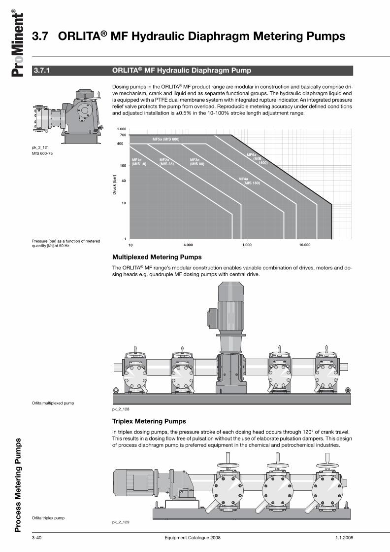
3.7 ORLITA® MF Hydraulic Diaphragm Metering Pumps
3-40 Equipment Catalogue 2008 1.1.2008
Pro
cess
Met
erin
g P
ump
s
3.7ORLITA® MF Hydraulic Diaphragm Metering Pumps
Dosing pumps in the ORLITA® MF product range are modular in construction and basically comprise dri-ve mechanism, crank and liquid end as separate functional groups. The hydraulic diaphragm liquid end is equipped with a PTFE dual membrane system with integrated rupture indicator. An integrated pressure relief valve protects the pump from overload. Reproducible metering accuracy under defined conditions and adjusted installation is ±0.5% in the 10-100% stroke length adjustment range.
Multiplexed Metering Pumps
The ORLITA® MF range’s modular construction enables variable combination of drives, motors and do-sing heads e.g. quadruple MF dosing pumps with central drive.
pk_2_128
Triplex Metering Pumps
In triplex dosing pumps, the pressure stroke of each dosing head occurs through 120° of crank travel. This results in a dosing flow free of pulsation without the use of elaborate pulsation dampers. This design of process diaphragm pump is preferred equipment in the chemical and petrochemical industries.
pk_2_129
3.7.1 ORLITA® MF Hydraulic Diaphragm Pump
pk_2_121
MfS 600-75
Pressure [bar] as a function of metered quantity [l/h] at 50 Hz
Orlita multiplexed pump
Orlita triplex pump
ProMinent_3 Prozessdosierpumpen.fm Seite 40 Montag, 17. Dezember 2007 4:33 16

1.1.2008 Equipment Catalogue 2008 3-41
Pro
cess
Met
erin
g P
ump
s
3.7 ORLITA® MF Hydraulic Diaphragm Metering Pumps
Type Of Drive
When ordering a multiplexed pump, the main and/or all externally mounted pumps require a separate Identcode.
Materials In Contact With Chemicals
Motor Data
For example a triplex pumpe (1.) : MF_aH3......................MF_aAR......................MF_aAR......................
Liquid end Vacuum and pres-sure valve housing
Valve seals Valve Valve seat Range
S1 (DIN) 1.4404 1.4571 Rubin 1.4571 DN 3S1 (ANSI) A 316 L N/A A 316 Ti Ruby A 316 TiS1 (DIN) 1.4404 1.4404 1.4571 1.4462 1.4462 ≥= DN6S1 (ANSI) A 316 L A 316 L A 316 Ti Duplex SS Duplex SSS2 (DIN) 1.4462 1.4462 1.4571 1.4462 1.4462 ≥= DN6S2 (ANSI) Duplex SS Duplex SS A 316 Ti Duplex SS Duplex SSS3 (DIN) 1.4539 1.4539 2.4610 1.4539 1.4539 ≥= DN6S3 (ANSI) A904L A904L Hastelloy C-4 A904L A904L
A 50 Hz 3 ph. 230/400 3 ph. 500 3 ph. 380/6603 ph. 400/690 3 ph. 415
B (adjustable 1:5) 50 Hz 3 ph. 230/400 3 ph. 500 3 ph. 380/6603 ph. 400/690 3 ph. 415
H 60 Hz 3 ph. 220/380 3 ph. 400K (adjustable 1:5) 60 Hz 3 ph. 220/380 3 ph. 400
ProMinent_3 Prozessdosierpumpen.fm Seite 41 Montag, 17. Dezember 2007 4:33 16

3.7 ORLITA® MF Hydraulic Diaphragm Metering Pumps
3-42 Equipment Catalogue 2008 1.1.2008
Pro
cess
Met
erin
g P
ump
s
Technical Data MfS 18 Single Pump 50 Hz
Technical Data MfS 18 Single Pump 60 Hz
3.7.2 ORLITA® MfS 18 (MF1a) Hydraulic Diaphragm Pump
Plunger Ø
Strokevolume
Pump capacity Qth in l/h per headat stroke rate n in 1/min
Identcode specification: [3 to 7]
Max.pres-
sure p
EfficiencyWG at
Standard type of valve
StandardconnectionSuction/Discharge side
70 88 108 140 200 100%Pres-sure
50%PRes-
sure mm cm3/
stroke[3] [4] [5] [6] [7] bar DIN/ISO ANSI/SME
7 0.58 2.4 3.0 3.7 4.8 6.9 400.0 0.50 0.70 DKu* DN 3 G1/4 internal 1/4" FNPT8 0.75 3.2 4.0 4.9 6.3 9.0 348.0 0.55 0.72 DKu* DN 3 G1/4 internal 1/4" FNPT
10 1.18 4.9 6.2 7.6 9.9 14.1 222.0 0.67 0.79 Ke*** DN 6 G3/8 internal 1/4" FNPT12 1.70 7.1 9.0 11.0 14.3 20.4 154.0 0.84 0.88 Ke*** DN 6 G3/8 internal 1/4" FNPT16 3.02 12.7 15.9 19.5 25.3 36.2 87.0 0.86 0.88 Ke*** DN 6 G3/8 internal 1/4" FNPT20 4.71 19.8 24.9 30.5 39.6 56.5 55.0 0.88 0.89 Ke*** DN 6 G3/8 internal 1/4" FNPT22 5.70 23.9 30.1 36.9 47.9 68.4 46.0 0.88 0.89 Ke*** DN 10/
DN 6G3/8 internal 1/2"x1/4"
FNPT25 7.36 30.9 38.9 47.7 61.9 88.4 35.0 0.89 0.89 Ke*** DN 10 G3/8 internal 1/2" FNPT27 8.59 36.1 45.3 55.7 72.1 103.1 30.0 0.89 0.89 Ke*** DN 10 G3/8 internal 1/2" FNPT30 10.60 44.5 56.0 68.7 89.1 127.2 24.0 0.89 0.89 Ke*** DN 10 DN 10 PN 40 1/2" #300RF36 15.27 64.1 80.6 98.9 128.3 183.2 17.0 0.89 0.89 Ke*** DN 16 DN 15 PN 40 3/4" #150RF40 18.85 79.2 99.5 122.1 158.3 226.2 13.0 0.89 0.89 Ke*** DN 16 DN 15 PN 40 3/4" #150RF44 22.81 95.8 120.4 147.8 191.6 273.7 11.0 0.89 0.90 Ke*** DN 16 DN 15 PN 40 3/4" #150RF50 29.45 123.7 155.5 190.9 247.4 353.4 8.0 0.89 0.90 Ke*** DN 16 DN 15 PN 40 3/4" #150RF65 49.77 209.1 262.8 322.5 418.1 597.3 5.0 0.90 0.90 Ke*** DN 16/
DN 25DN 15/25 PN 40
3/4"x1" #150RF
Plunger Ø
Strokevolume
Pump capacity Qth in l/h per headat stroke rate n in 1/min
Identcode specification: [2 to 6]
Max.pres-
sure p
EfficiencyWG at
Standard type of valve
StandardconnectionSuction/Discharge side
67 87 106 130 168 100%Pres-sure
50%Pres-sure
mm cm3/stroke
[2] [3] [4] [5] [6] bar DIN/ISO ANSI/SME
7 0.58 2.3 3.0 3.7 4.5 5.8 400.0 0.50 0.70 DKu* DN 3 G1/4 internal 1/4" FNPT8 0.75 3.0 3.9 4.8 5.9 7.6 348.0 0.55 0.72 DKu* DN 3 G1/4 internal 1/4" FNPT
10 1.18 4.7 6.1 7.5 9.2 11.9 222.0 0.67 0.79 Ke*** DN 6 G3/8 internal 1/4" FNPT12 1.70 6.8 8.9 10.8 13.2 17.1 154.0 0.84 0.88 Ke*** DN 6 G3/8 internal 1/4" FNPT16 3.02 12.1 15.7 19.2 23.5 30.4 87.0 0.86 0.88 Ke*** DN 6 G3/8 internal 1/4" FNPT20 4.71 18.9 24.6 30.0 36.8 47.5 55.0 0.88 0.89 Ke*** DN 6 G3/8 internal 1/4" FNPT22 5.70 22.9 29.8 36.3 44.5 57.5 46.0 0.88 0.89 Ke*** DN 10/
DN 6G3/8 internal 1/2"x1/4"
FNPT25 7.36 29.6 38.4 46.8 57.4 74.2 35.0 0.89 0.89 Ke*** DN 10 G3/8 internal 1/2" FNPT27 8.59 34.5 44.8 54.6 67.0 86.6 30.0 0.89 0.89 Ke*** DN 10 G3/8 internal 1/2" FNPT30 10.60 42.6 55.3 67.4 82.7 106.9 24.0 0.89 0.89 Ke*** DN 10 DN 10 PN 40 1/2" #300RF36 15.27 61.4 79.7 97.1 119.1 153.9 17.0 0.89 0.89 Ke*** DN 16 DN 15 PN 40 3/4" #150RF40 18.85 75.8 98.4 119.9 147.0 190.0 13.0 0.89 0.89 Ke*** DN 16 DN 15 PN 40 3/4" #150RF44 22.81 91.7 119.1 145.1 177.9 229.9 11.0 0.89 0.90 Ke*** DN 16 DN 15 PN 40 3/4" #150RF50 29.45 118.4 153.7 187.3 229.7 296.9 8.0 0.89 0.90 Ke*** DN 16 DN 15 PN 40 3/4" #150RF65 49.77 200.1 259.8 316.6 388.2 501.7 5.0 0.90 0.90 Ke*** DN 16/
DN 25DN 15/25 PN 40
3/4"x1" #150RF
* Double ball*** Cone
Note: Further variants on request In layouts conforming to API a power reserve of at least 10% must be allowed for All hydraulic performance data are based on water at 20 °C
ProMinent_3 Prozessdosierpumpen.fm Seite 42 Montag, 17. Dezember 2007 4:33 16

1.1.2008 Equipment Catalogue 2008 3-43
Pro
cess
Met
erin
g P
ump
s
3.7 ORLITA® MF Hydraulic Diaphragm Metering Pumps
Identcode Ordering System
Motor-Driven Metering Pump ORLITA® MfS18 (MF1a)
* For other pump configurations see Type Of Drive page → 3-41
MF1a Drive typeV1 Main drive vertical* AL Drive module left-hand M Modified **Z1 Main drive central* AR Drive module right-hand
Plunger diameter007 7 mm 012 12 mm 022 22 mm 036 36 mm 050 50 mm008 8 mm 016 16 mm 025 25 mm 040 40 mm 065 65 mm010 10 mm 020 20 mm 030 30 mm 044 44 mm 050 50 mm
Stroke rate 50 (60) Hz3 70 (84) Strokes/min 5 108 (129) Strokes/min 7 200 (-) Strokes/min4 88 (105) Strokes/min 6 140 (168) Strokes/min
Liquid end material (including valve materials)S1 Stainless steel (see table, sheet 2)
Temperature of pumped medium0 -10 °C to 80 °C 2 -40 °C to 60 °C 4 10 °C to 150 °C1 -25 °C to 60 °C 3 10 °C to 115 °C
Displacer format0 PTFE multi-layer diaphragm1 PTFE multi-layer diaphragm with pressure gauge
Liquid end version0 Standard 2 Standard double valve1 Standard with spring 3 Standard double valve with spring
Hydraulic connection suction sideG Thread DIN/ISO A Flange ANSIN Thread NPT/ANSI D Flange DIN/ISO
Hydraulic connection discharge sideG Thread DIN/ISO A Flange ANSIN Thread NPT/ANSI D Flange DIN/ISO
Version0 no features 2 Dosing head polished1 Dosing head heating 3 Special paint finish
Power connectorA Standard voltages 50HzB Standard voltages 50Hz adjustableH Standard voltages 60HzK Standard voltages 60Hz adjustable0 Externally mounted pump1 without motor with IEC flange2 without motor with NEMA flange
Electrical protection system / explosion protection0 IP 551 IP 56A IP 55 EExnB IP 55 EExeC IP 55 EExdeD IP 56 EExnE IP 56 EExeF IP 56 EExde
Electrical options0 no options1 Stroke sensor
Stroke length adjustment0 manual1 0/4-20 mA without Ex2 0/4-20 mA Ex Zone 23 0/4-20 mA Ex Zone 14 0/4-20 mA without EX offshore5 0/4-20 mA Ex Zone 2 offshore6 0/4-20 mA Ex Zone 1 offshore
Environmental conditions0 -20 °C to 40 °C1 -40 °C to 40 °C2 0 °C to 55 °C
Approvals0 CE1 API 6752 VDMA3 ATEX4 ATEX / API 6755 VDMA / ATEX
** Modified version (M) is possible for each ID character of the Identcode.
ProMinent_3 Prozessdosierpumpen.fm Seite 43 Montag, 17. Dezember 2007 4:33 16

3.7 ORLITA® MF Hydraulic Diaphragm Metering Pumps
3-44 Equipment Catalogue 2008 1.1.2008
Pro
cess
Met
erin
g P
ump
s
Technical Data MfS 35 Single Pump 50 Hz
Technical Data MfS 35 Single Pump 60 Hz
3.7.3 ORLITA® MfS 35 (MF2a) Hydraulic Diaphragm Pump
Plunger Ø
Strokevolume
Pump capacity Qth in l/h per headat stroke rate n in 1/min
Identcode specification: [3 to 7]
Max.pres-
sure p
EfficiencyWG at
Standard type of valve
StandardconnectionSuction/Discharge side
70 88 108 140 200 100%Pres-sure
50% Pres-sure
mm cm3/stroke
[3] [4] [5] [6] [7] bar DIN/ISO ANSI/SME
7 0.77 3.2 4.1 5.0 6.5 9.2 400.0 0.50 0.70 DKu* DN 3 G1/4 internal 1/4" FNPT8 1.01 4.2 5.3 6.5 8.4 12.1 400.0 0.50 0.70 DKu* DN 3 G1/4 internal 1/4" FNPT
10 1.57 6.6 8.3 10.2 13.2 18.8 400.0 0.50 0.70 Ke*** DN 6 G3/8 internal 1/4" FNPT12 2.26 9.5 11.9 14.7 19.0 27.1 309.0 0.79 0.85 Ke*** DN 6 G3/8 internal 1/4" FNPT16 4.02 16.9 21.2 26.1 33.8 48.3 174.0 0.83 0.86 Ke*** DN 6 G3/8 internal 1/4" FNPT20 6.28 26.4 33.2 40.7 52.8 75.4 111.0 0.86 0.88 Ke*** DN 6 G3/8 internal 1/4" FNPT22 7.60 31.9 40.1 49.3 63.9 91.2 92.0 0.86 0.88 Ke*** DN 10/
DN 6G3/8 internal 1/2"x1/4"
FNPT25 9.82 41.2 51.8 63.6 82.5 117.8 71.0 0.87 0.88 Ke*** DN 10 G3/8 internal 1/2" FNPT27 11.45 48.1 60.5 74.2 96.2 137.4 61.0 0.87 0.88 Ke*** DN 10 G3/8 internal 1/2" FNPT30 14.14 59.4 74.6 91.6 118.8 169.6 49.0 0.88 0.89 Ke*** DN 10 DN 10 PN 100 1/2" #300RF36 20.36 85.5 107.5 131.9 171.0 244.3 34.0 0.88 0.89 Ke*** DN 16 DN 15 PN 40 3/4" #300RF40 25.13 105.6 132.7 162.9 211.1 301.6 27.0 0.89 0.89 Ke*** DN 16 DN 15 PN 40 3/4" #300RF44 30.41 127.7 160.6 197.1 255.4 364.9 23.0 0.89 0.89 Ke*** DN 16 DN 15 PN 40 3/4" #300RF50 39.27 164.9 207.3 254.5 329.9 471.2 17.0 0.89 0.89 Ke*** DN 16 DN 15 PN 40 3/4" #150RF65 66.37 278.7 350.4 430.1 557.5 796.4 10.0 0.89 0.90 Ke*** DN 16/
DN 25DN 15/25 PN 40
3/4"x1" #150RF
Plunger Ø
Strokevolume
Pump capacity Qth in l/h per headat stroke rate n in 1/min
Identcode specification: [2 to 6]
Max.pres-
sure p
EfficiencyWG at
Standard type of valve
StandardconnectionSuction/Discharge side
67 87 106 130 168 100%Pres-sure
50% Pres-sure
mm cm3/stroke
[2] [3] [4] [5] [6] bar DIN/ISO ANSI/SME
7 0.77 3.1 4.0 4.9 6.0 7.8 400.0 0.50 0.70 DKu* DN 3 G1/4 internal 1/4" FNPT8 1.01 4.0 5.2 6.4 7.8 10.1 400.0 0.50 0.70 DKu* DN 3 G1/4 internal 1/4" FNPT
10 1.57 6.3 8.2 10.0 12.3 15.8 400.0 0.50 0.70 Ke*** DN 6 G3/8 internal 1/4" FNPT12 2.26 9.1 11.8 14.4 17.6 22.8 309.0 0.79 0.85 Ke*** DN 6 G3/8 internal 1/4" FNPT16 4.02 16.2 21.0 25.6 31.4 40.5 174.0 0.83 0.86 Ke*** DN 6 G3/8 internal 1/4" FNPT20 6.28 25.3 32.8 40.0 49.0 63.3 111.0 0.86 0.88 Ke*** DN 6 G3/8 internal 1/4" FNPT22 7.60 30.6 39.7 48.4 59.3 76.6 92.0 0.86 0.88 Ke*** DN 10/
DN 6G3/8 internal 1/2"x1/4"
FNPT25 9.82 39.5 51.2 62.4 76.6 99.0 71.0 0.87 0.88 Ke*** DN 10 G3/8 internal 1/2" FNPT27 11.45 46.0 59.8 72.8 89.3 115.4 61.0 0.87 0.88 Ke*** DN 10 G3/8 internal 1/2" FNPT30 14.14 56.8 73.8 89.9 110.3 142.5 49.0 0.88 0.89 Ke*** DN 10 DN 10 PN 100 1/2" #300RF36 20.36 81.8 106.3 129.5 158.8 205.2 34.0 0.88 0.89 Ke*** DN 16 DN 15 PN 40 3/4" #300RF40 25.13 101.0 131.2 159.8 196.0 253.3 27.0 0.89 0.89 Ke*** DN 16 DN 15 PN 40 3/4" #300RF44 30.41 122.3 158.7 193.4 237.2 306.5 23.0 0.89 0.89 Ke*** DN 16 DN 15 PN 40 3/4" #300RF50 39.27 157.9 205.0 249.8 306.3 395.8 17.0 0.89 0.89 Ke*** DN 16 DN 15 PN 40 3/4" #150RF65 66.37 266.8 346.4 422.1 517.7 669.0 10.0 0.89 0.90 Ke*** DN 16/
DN25DN 15/25 PN 40
3/4"x1" #150RF
* Double ball*** Cone
Note: Further variants on request In layouts conforming to API a power reserve of at least 10% must be allowed for All hydraulic performance data are based on water at 20 °C
ProMinent_3 Prozessdosierpumpen.fm Seite 44 Montag, 17. Dezember 2007 4:33 16

1.1.2008 Equipment Catalogue 2008 3-45
Pro
cess
Met
erin
g P
ump
s
3.7 ORLITA® MF Hydraulic Diaphragm Metering Pumps
Identcode Ordering System
Motor-Driven Metering Pump ORLITA® MfS35 (MF2a)
* For further pump configurations see Type Of Drive page → 3-41
MF2a Drive typeV1 Main drive vertical * AL Drive module left-hand M Modified **Z1 Main drive central * AR Drive module right-hand
Plunger diameter007 7 mm 012 12 mm 022 22 mm 036 36 mm 050 50 mm008 8 mm 016 16 mm 025 25 mm 040 40 mm 065 65 mm010 10 mm 020 20 mm 030 30 mm 044 44 mm
Stroke rate 50 (60) Hz2 (-) 67 Strokes/min 4 88 (105) Strokes/min 6 140 (168) Strokes/min3 70 (84) Strokes/min 5 108 (129) Strokes/min 7 200 (-) Strokes/min
Liquid end material (including valve materials)S1 Stainless steel (see table, sheet 2)
Temperature of pumped medium0 -10 °C to 80 °C 2 -40 °C to 60 °C 4 10 °C to 150 °C1 -25 °C to 60 °C 3 10 °C to 115 °C
Displacer format0 PTFE multi-layer diaphragm1 PTFE multi-layer diaphragm with pressure gauge
Liquid end version0 Standard 2 Standard + double valve1 Standard with spring 3 Standard + double valve with spring
Hydraulic connection suction sideG Thread DIN/ISO A Flange ANSIN Thread NPT/ANSI D Flange DIN/ISO
Hydraulic connection discharge sideG Thread DIN/ISO A Flange ANSIN Thread NPT/ANSI D Flange DIN/ISO
Version0 no features 2 Dosing head polished1 Dosing head heating 3 Special paint finish
Power connectorA Standard voltages 50HzB Standard voltages 50Hz adjustableH Standard voltages 60HzK Standard voltages 60Hz adjustable0 Externally mounted pump1 without motor with IEC flange2 without motor with NEMA flange
Electrical protection system / explosion protection0 IP 55 D IP 56 EExn1 IP 56 E IP 56 EExeA IP 55 EExn F IP 56 EExdeB IP 55 EExe K IP 65 EExdeC IP 55 EExde
Electrical options0 no options1 Stroke sensor
Stroke length adjustment0 manual1 0/4-20 mA without Ex2 0/4-20 mA Ex Zone 23 0/4-20 mA Ex Zone 14 0/4-20 mA without EX offshore5 0/4-20 mA Ex Zone 2 offshore6 0/4-20 mA Ex Zone 1 offshore
Environmental conditions0 -20 °C to 40 °C1 -40 °C to 40 °C2 0 °C to 55 °C
Approvals0 CE1 API 6752 VDMA3 ATEX4 ATEX / API 6755 VDMA / ATEX
** Modified design (M) is available with every Identcode feature
ProMinent_3 Prozessdosierpumpen.fm Seite 45 Montag, 17. Dezember 2007 4:33 16

3.7 ORLITA® MF Hydraulic Diaphragm Metering Pumps
3-46 Equipment Catalogue 2008 1.1.2008
Pro
cess
Met
erin
g P
ump
s
Technical Data MfS 80 Single Pump 50 Hz
Technical Data MfS 80 Single Pump 60 Hz
3.7.4 ORLITA® MfS 80 (MF3a) Hydraulic Diaphragm Pump
Plunger Ø
Strokevolume
Pump capacity Qth in l/h per headat stroke rate n in 1/min
Identcode specification: [3 to 8]
Max.pres-
sure p
EfficiencyWG at
Standard type of valve
StandardconnectionSuction/Discharge side
70 90 115 134 152 194 100%Pres-sure
50%Pres-sure
mm cm3/stroke
[3] [4] [5] [6] [7] [8] bar DIN/ISO ANSI/SME
16 4.02 16.9 21.7 27.7 32.3 36.7 46.8 400.0 0.75 0.83 Ke*** DN 6 G 3/8 1/4" FNPT20 6.28 26.4 33.9 43.4 50.5 57.3 73.1 400.0 0.75 0.83 Ke*** DN 6 G 3/8 1/4" FNPT22 7.60 31.9 41.1 52.5 61.1 69.3 88.5 360.0 0.79 0.80 Ke*** DN 10/
DN 6G 3/8 1/2" x 1/4"
FNPT25 9.82 41.2 53.0 67.7 78.9 89.5 114.3 285.0 0.79 0.85 Ke*** DN 10 G 3/8 1/2" FNPT27 11.45 48.1 61.8 79.0 92.1 104.4 133.3 244.0 0.81 0.85 Ke*** DN 10 G 3/8 1/2" FNPT30 14.14 59.4 76.3 97.5 113.7 128.9 164.6 198.0 0.83 0.86 Ke*** DN 10 DN 10 PN 250 1/2" 1500RF36 20.36 85.5 109.9 140.5 163.7 185.7 237.0 137.0 0.85 0.87 Ke*** DN 16 DN 15 PN 160 3/4" 1500RF40 25.13 105.6 135.7 173.4 202.1 229.2 292.5 111.0 0.86 0.88 Ke*** DN 16 DN 15 PN 160 3/4" 1500RF44 30.41 127.7 164.2 209.8 244.5 277.3 354.0 98.0 0.86 0.88 Ke*** DN 16 DN 15 PN 100 3/4" 600RF50 39.27 164.9 212.1 271.0 315.7 358.1 457.1 71.0 0.87 0.88 Ke*** DN 16 DN 15 PN 100 3/4" 600RF65 66.37 278.7 358.4 457.9 533.6 605.3 772.5 40.0 0.88 0.89 Ke*** DN 16/
DN 25DN 25 PN 40 1" 300RF
80 100.53 422.2 542.9 693.7 808.3 916.8 1,170.2 25.0 0.89 0.89 Ke*** DN 25 DN 25 PN 40 1" 300RF100 157.08 659.7 848.2 1,083.8 1,262.9 1,432.6 1,828.4 17.0 0.89 0.89 Ke*** DN 32 DN 32 PN 40 1 1/2" 150RF120 226.19 950.0 1,221.5 1,560.7 1,818.6 2,062.9 12.0 0.89 0.89 Ke*** DN 32 DN 32 PN 40 1 1/2" 150RF140 307.88 1,293.1 1,662.5 2,124.3 2,475.3 2,807.8 9.0 0.89 0.90 Ke*** DN 40 DN 40 PN 16 1 1/2" 150RF150 353.43 1,484.4 1,908.5 2,438.7 2,841.6 3,223.3 7.0 0.89 0.90 Ke*** DN 40 DN 40 PN 16 1 1/2" 150RF
Plunger Ø
Strokevolume
Pump capacity Qth in l/h per headat stroke rate n in 1/min
Identcode specification: [2 to 7]
Max.pres-
sure p
EfficiencyWG at
Standard type of valve
StandardconnectionSuction/Discharge side
73 84 120 138 155 182 100%Pres-sure
50%Pres-sure
mm cm3/stroke
[2] [3] [4] [5] [6] [7] bar DIN/ISO ANSI/SME
16 4.02 17.6 20.3 29.0 33.3 37.4 43.9 400.0 0.75 0.83 Ke*** DN 6 G 3/8 1/4" FNPT20 6.28 27.5 31.7 45.2 52.0 58.4 68.6 400.0 0.75 0.83 Ke*** DN 6 G 3/8 1/4" FNPT22 7.60 33.3 38.3 54.7 62.9 70.7 83.0 360.0 0.79 0.80 Ke*** DN 10/
DN 6G 3/8 1/2" x 1/4" FNPT
25 9.82 43.0 49.5 70.7 81.3 91.3 107.2 285.0 0.79 0.85 Ke*** DN 10 G 3/8 1/2" FNPT27 11.45 50.2 57.7 82.4 94.8 106.5 125.0 244.0 0.81 0.85 Ke*** DN 10 G 3/8 1/2" FNPT30 14.14 61.9 71.3 101.8 117.1 131.5 154.4 198.0 0.83 0.86 Ke*** DN 10 DN 10 PN 250 1/2" 1500RF36 20.36 89.2 102.6 146.6 168.6 189.3 222.3 137.0 0.85 0.87 Ke*** DN 16 DN 15 PN 160 3/4" 1500RF40 25.13 110.1 126.7 181.0 208.1 233.7 274.4 111.0 0.86 0.88 Ke*** DN 16 DN 15 PN 160 3/4" 1500RF44 30.41 133.2 153.3 219.0 251.8 282.8 332.1 98.0 0.86 0.88 Ke*** DN 16 DN 15 PN 100 3/4" 600RF50 39.27 172.0 197.9 282.7 325.2 365.2 428.8 71.0 0.87 0.88 Ke*** DN 16 DN 15 PN 100 3/4" 600RF65 66.37 290.7 334.5 477.8 549.5 617.2 724.7 40.0 0.88 0.89 Ke*** DN 16/
DN 25DN 25 PN 40 1" 300RF
80 100.53 440.3 506.7 723.8 832.4 934.9 1,097.8 25.0 0.89 0.89 Ke*** DN 25 DN 25 PN 40 1" 300RF100 157.08 688.0 791.7 1,131.0 1,300.6 1,460.8 1,715.3 17.0 0.89 0.89 Ke*** DN 32 DN 32 PN 40 1 1/2" 150RF120 226.19 990.7 1,140.0 1,628.6 1,872.9 2,103.6 12.0 0.89 0.89 Ke*** DN 32 DN 32 PN 40 1 1/2" 150RF140 307.88 1,348.5 1,551.7 2,216.7 2,549.2 2,863.2 9.0 0.89 0.90 Ke*** DN 40 DN 40 PN 16 1 1/2" 150RF150 353.43 1,548.0 1,781.3 2,544.7 2,926.4 3,286.9 7.0 0.89 0.90 Ke*** DN 40 DN 40 PN 16 1 1/2" 150RF
*** Cone
Note: Further variants on request In layouts conforming to API a power reserve of at least 10% must be allowed for All hydraulic performance data are based on water at 20 °C
ProMinent_3 Prozessdosierpumpen.fm Seite 46 Montag, 17. Dezember 2007 4:33 16

1.1.2008 Equipment Catalogue 2008 3-47
Pro
cess
Met
erin
g P
ump
s
3.7 ORLITA® MF Hydraulic Diaphragm Metering Pumps
Identcode Ordering System
Motor-Driven Metering Pump ORLITA® MfS80 (MF3a)
* For further pump configurations see Type Of Drive page → 3-41
MF3a Drive typeH1 Main drive horizontal* Z1 Main drive central* AR Drive module right-handV1 Main drive vertical* AL Drive module left-hand M Modified **
Plunger diameter016 16 mm 027 27 mm 044 44 mm 100 100 mm 160 160 mm020 20 mm 030 30 mm 050 50 mm 120 120 mm022 22 mm 036 36 mm 065 65 mm 140 140 mm025 25 mm 040 40 mm 080 80 mm 150 150 mm
Stroke rate 50 (60) Hz2 (-) 73 Strokes/min 4 85 (102) Strokes/min 6 145 (174) Strokes/min 8 194 (-) Strokes/min3 68 (81) Strokes/min 5 113 (135) Strokes/min 7 174 Strokes/min
Liquid end material (including valve materials)S1 Stainless steel (see table, sheet 2)
Temperature of pumped medium0 -10 °C to 80 °C 2 -40 °C to 60 °C 4 10 °C to 150 °C1 -25 °C to 60 °C 3 10 °C to 115 °C
Displacer format0 PTFE multi-layer diaphragm1 PTFE multi-layer diaphragm with pressure gauge
Liquid end version0 Standard 2 Standard + double valve1 Standard with spring 3 Standard + double valve with spring
Hydraulic connection suction sideG Thread DIN/ISO A Flange ANSIN Thread NPT/ANSI D Flange DIN/ISO
Hydraulic connection discharge sideG Thread DIN/ISO A Flange ANSIN Thread NPT/ANSI D Flange DIN/ISO
Version0 no features 2 Dosing head polished1 Dosing head heating 3 Special paint finish
Power connectorA Standard voltage 50HzB Standard voltage 50Hz adjustableH Standard voltage 60HzK Standard voltage 60Hz adjustable0 Externally mounted pump1 without motor with IEC flange2 without motor with NEMA flange
Electrical protection system / explosion protection0 IP 55 D IP 56 EExn1 IP 56 E IP 56 EExeA IP 55 EExn F IP 56 EExdeB IP 55 EExe K IP 65 EExdeC IP 55 EExde
Electrical options0 no options1 Stroke sensor
Stroke length adjustment0 manual1 0/4-20 mA without Ex2 0/4-20 mA Ex Zone 23 0/4-20 mA Ex Zone 14 0/4-20 mA Ex without EX offshore5 0/4-20 mA Ex Zone 2 offshore6 0/4-20 mA Ex Zone 1 offshore
Environmental conditions0 -20 °C to 40 °C1 -40 °C to 40 °C2 0 °C to 55 °C
Approvals0 CE1 API 6752 VDMA3 ATEX4 ATEX / API 6755 VDMA / ATEX
** Modified design (M) is available with every Identcode feature
ProMinent_3 Prozessdosierpumpen.fm Seite 47 Montag, 17. Dezember 2007 4:33 16

3.7 ORLITA® MF Hydraulic Diaphragm Metering Pumps
3-48 Equipment Catalogue 2008 1.1.2008
Pro
cess
Met
erin
g P
ump
s
Technical Data MfS 180 Single Pump 50 Hz
Technical Data MfS 180 Single Pump 60 Hz
3.7.5 ORLITA® MfS 180 (MF4a) Hydraulic Diaphragm Pump
Plunger Ø
Strokevolume
Pump capacity Qth in l/h per headat stroke rate n in 1/min
Identcode specification: [3 to 8]
Max.pres-
sure p
EfficiencyWG at
Standard type of valve
StandardconnectionSuction/Discharge side
67 88 103 137 154 173 100%Pres-sure
50%Pres-sure
mm cm3/stroke
[3] [4] [5] [6] [7] [8] bar DIN/ISO ANSI/SME
25 19.63 78.9 103.7 121.3 161.4 181.4 203.8 366.0 0.77 0.83 Ke*** DN 16 DN 15 PN 400 3/4" 2500RTJ30 28.27 113.7 149.3 174.7 232.4 261.3 293.5 254.0 0.81 0.85 Ke*** DN 16 DN 15 PN 320 3/4" 1500RF36 40.72 163.7 215.0 251.6 334.7 376.2 422.6 176.0 0.83 0.86 Ke*** DN 16 DN 15 PN 250 1" 1500RF38 45.36 182.4 239.5 280.4 372.9 419.2 470.9 158.0 0.84 0.87 Ke*** DN 16 DN 15 PN 160 1" 1500RF40 50.27 202.1 265.4 310.6 413.2 464.5 521.8 143.0 0.85 0.87 Ke*** DN 16 DN 15 PN 160 1" 1500RF44 60.82 244.5 321.1 375.9 500.0 562.0 631.3 118.0 0.85 0.87 Ke*** DN 25 DN 25 PN 160 1" 1500RF46 66.48 267.2 351.0 410.8 546.4 614.2 690.0 108.0 0.86 0.88 Ke*** DN 25 DN 25 PN 160 1" 1500RF48 72.38 291.0 382.2 447.3 595.0 668.8 751.3 108.0 0.86 0.88 Ke*** DN 25 DN 25 PN 160 1" 1500RF50 78.54 315.7 414.7 485.4 645.6 725.7 815.2 91.0 0.86 0.88 Ke*** DN 25 DN 25 PN 100 1" 600RF55 95.03 382.0 501.8 587.3 781.2 878.1 986.4 75.0 0.87 0.88 Ke*** DN 25 DN 25 PN 100 1" 600RF60 113.10 454.7 597.2 698.9 929.7 1,045.0 1,174.0 63.0 0.87 0.89 Ke*** DN 25 DN 25 PN 64 1" 600RF65 132.73 533.6 700.8 820.3 1,091.1 1,226.4 1,377.8 54.0 0.88 0.89 Ke*** DN 32 DN 40 PN 64 1 1/2" 600RF70 153.94 618.8 812.8 951.3 1,265.4 1,422.4 1,597.9 46.0 0.88 0.89 Ke*** DN 32 DN 40 PN 64 1 1/2" 600RF75 176.71 710.4 933.1 1,092.1 1,452.6 1,632.8 1,834.3 40.0 0.88 0.89 Ke*** DN 32 DN 40 PN 64 1 1/2" 300RF80 201.06 808.3 1,061.6 1,242.6 1,652.7 1,857.8 2,087.0 35.0 0.88 0.89 Ke*** DN 40 DN 40 PN 40 1 1/2" 300RF85 226.98 912.5 1,198.5 1,402.7 1,865.8 2,097.3 2,356.1 31.0 0.88 0.89 Ke*** DN 40 DN 40 PN 40 1 1/2" 300RF90 254.47 1,023.0 1,343.6 1,572.6 2,091.7 2,351.3 2,641.4 28.0 0.89 0.89 Ke*** DN 40 DN 40 PN 40 1 1/2" 300RF
100 314.16 1,262.9 1,658.8 1,941.5 2,582.4 2,902.8 3,261.0 22.0 0.89 0.89 Ke*** DN 50 DN 50 PN 40 2" 150RF115 415.48 1,670.2 2,193.7 2,567.6 3,415.2 3,839.0 17.0 0.89 0.89 Ke*** DN 65 DN 65 PN 40 2 1/2" 150RF135 572.56 2,301.7 3,023.1 3,538.4 4,706.4 5,290.4 12.0 0.89 0.90 Ke*** DN 65 DN 65 PN 16 2 1/2" 150RF
Plunger Ø
Strokevolume
Pump capacity Qth in l/h per headat stroke rate n in 1/min
Identcode specification: [2 to 7]
Max.pres-
sure p
EfficiencyWG at
Standard type of valve
StandardconnectionSuction/Discharge side
71 91 106 139 164 184 100%Pres-sure
50%Pres-sure
mm cm3/stroke
[2] [3] [4] [5] [6] [7] bar DIN/ISO ANSI/SME
25 19.63 83.6 107.2 124.9 163.8 193.2 216.8 352.0 0.77 0.83 Ke*** DN 16 DN 15 PN 400 3/4" 2500RTJ30 28.27 120.4 154.4 179.8 235.8 278.2 312.1 254.0 0.81 0.85 Ke*** DN 16 DN 15 PN 320 3/4" 1500RF36 40.72 173.4 222.3 258.9 339.6 400.6 449.5 176.0 0.83 0.86 Ke*** DN 16 DN 15 PN 250 1" 1500RF38 45.36 193.3 247.7 288.5 378.3 446.4 500.8 158.0 0.84 0.87 Ke*** DN 16 DN 15 PN 160 1" 1500RF40 50.27 214.1 274.4 319.7 419.2 494.6 554.9 143.0 0.85 0.87 Ke*** DN 16 DN 15 PN 160 1" 1500RF44 60.82 259.1 332.1 386.8 507.2 598.5 671.5 118.0 0.85 0.87 Ke*** DN 25 DN 25 PN 160 1" 1500RF46 66.48 283.2 363.0 422.8 554.4 654.1 733.9 108.0 0.86 0.88 Ke*** DN 25 DN 25 PN 160 1" 1500RF48 72.38 308.3 395.2 460.4 603.7 712.2 799.1 108.0 0.86 0.88 Ke*** DN 25 DN 25 PN 160 1" 1500RF50 78.54 334.6 428.8 499.5 655.0 772.8 867.1 91.0 0.86 0.88 Ke*** DN 25 DN 25 PN 100 1" 600RF55 95.03 404.8 518.9 604.4 792.6 935.1 1,049.2 75.0 0.87 0.88 Ke*** DN 25 DN 25 PN 100 1" 600RF60 113.10 481.8 617.5 719.3 943.2 1,112.9 1,248.6 63.0 0.87 0.89 Ke*** DN 25 DN 25 PN 64 1" 600RF65 132.73 565.4 724.7 844.2 1,107.0 1,306.1 1,465.4 54.0 0.88 0.89 Ke*** DN 32 DN 40 PN 64 1 1/2" 600RF70 153.94 655.8 840.5 979.0 1,283.8 1,514.8 1,699.5 46.0 0.88 0.89 Ke*** DN 32 DN 40 PN 64 1 1/2" 600RF75 176.71 752.8 964.9 1,123.9 1,473.8 1,738.9 1,950.9 40.0 0.88 0.89 Ke*** DN 32 DN 40 PN 64 1 1/2" 300RF80 201.06 856.5 1,097.8 1,278.8 1,676.9 1,978.4 2,219.7 35.0 0.88 0.89 Ke*** DN 40 DN 40 PN 40 1 1/2" 300RF85 226.98 966.9 1,239.3 1,443.6 1,893.0 2,233.5 2,505.9 31.0 0.88 0.89 Ke*** DN 40 DN 40 PN 40 1 1/2" 300RF90 254.47 1,084.0 1,389.4 1,618.4 2,122.3 2,504.0 2,809.3 28.0 0.89 0.89 Ke*** DN 40 DN 40 PN 40 1 1/2" 300RF
100 314.16 1,338.3 1,715.3 1,998.1 2,620.1 3,091.3 3,468.3 22.0 0.89 0.89 Ke*** DN 50 DN 50 PN 40 2" 150RF115 415.48 1,769.9 2,268.5 2,642.4 3,465.1 17.0 0.89 0.89 Ke*** DN 65 DN 65 PN 40 2 1/2" 150RF135 572.56 2,439.1 3,126.2 3,641.5 4,775.1 11.0 0.89 0.90 Ke*** DN 65 DN 65 PN 16 2 1/2" 150RF
*** Cone
Note: Further variants on request In layouts conforming to API a power reserve of at least 10% must be allowed for All hydraulic performance data are based on water at 20 °C
ProMinent_3 Prozessdosierpumpen.fm Seite 48 Montag, 17. Dezember 2007 4:33 16

1.1.2008 Equipment Catalogue 2008 3-49
Pro
cess
Met
erin
g P
ump
s
3.7 ORLITA® MF Hydraulic Diaphragm Metering Pumps
Identcode Ordering System
Motor-Driven Metering Pump ORLITA® MfS180 (MF4a)
* For further pump configurations see Type Of Drive page → 3-41
MF4a Drive typeH1 Main drive horizontal* Z1 Main drive central * AR Drive module right-handV1 Main drive vertical* AL Drive module left-hand M Modified **
Plunger diameter025 25 mm 040 40 mm 055 55 mm 075 75 mm 100 100 mm030 30 mm 044 44 mm 060 60 mm 080 80 mm 115 115 mm036 36 mm 046 46 mm 065 65 mm 085 85 mm 135 135 mm038 38 mm 050 50 mm 070 70 mm 090 90 mm
Stroke rate 50 (60) Hz2 (-) 71 Strokes/min 4 88 (105) Strokes/min 6 140 (168) Strokes/min 8 173 (-) Strokes/min3 72 (86) Strokes/min 5 123 (147) Strokes/min 7 172 Strokes/min
Liquid end material (including valve materials)S1 Stainless steel (see table, sheet 2)
Temperature of pumped medium0 -10 °C to 80 °C 2 -40 °C to 60 °C 4 10 °C to 150 °C1 -25 °C to 60 °C 3 10 °C to 115 °C
Displacer format0 PTFE multi-layer diaphragm1 PTFE multi-layer diaphragm with pressure gauge
Liquid end version0 Standard 2 Standard + double valve1 Standard with spring 3 Standard + double valve with spring
Hydraulic connection suction sideG Thread DIN/ISO A Flange ANSIN Thread NPT/ANSI D Flange DIN/ISO
Hydraulic connection discharge sideG Thread DIN/ISO A Flange ANSIN Thread NPT/ANSI D Flange DIN/ISO
Version0 no features 2 Dosing head polished1 Dosing head heating 3 Special paint finish
Power connectorA Standard voltage 50HzB Standard voltage 50Hz adjustableH Standard voltage 60HzK Standard voltage 60Hz adjustable0 Externally mounted pump1 without motor with IEC flange2 without motor with NEMA flange
Electrical protection system / explosion protection0 IP 55 D IP 56 EExn1 IP 56 E IP 56 EExeA IP 55 EExn F IP 56 EExdeB IP 55 EExe K IP 65 EExdeC IP 55 EExde
Electrical options0 no options1 Stroke sensor
Stroke length adjustment0 manual1 0/4-20 mA without Ex2 0/4-20 mA Ex Zone 23 0/4-20 mA Ex Zone 14 0/4-20 mA Ex without EX offshore5 0/4-20 mA Ex Zone 2 offshore6 0/4-20 mA Ex Zone 1 offshore
Environmental conditions0 -20 °C to 40 °C1 -40 °C to 40 °C2 0 °C to 55 °C
Approvals0 CE1 API 6752 VDMA3 ATEX4 ATEX / API 6755 VDMA / ATEX
** Modified design (M) is available with every Identcode feature
ProMinent_3 Prozessdosierpumpen.fm Seite 49 Montag, 17. Dezember 2007 4:33 16

3.7 ORLITA® MF Hydraulic Diaphragm Metering Pumps
3-50 Equipment Catalogue 2008 1.1.2008
Pro
cess
Met
erin
g P
ump
s
Technical Data MfS 600 Single Pump 50 Hz
Technical Data MfS 600 Single Pump 60 Hz
3.7.6 ORLITA® MfS 600 (MF5a) Hydraulic Diaphragm Pump
Plunger Ø
Strokevolume
Pump capacity Qth in l/h per headat stroke rate n in 1/min
Identcode specification: [3 to 8]
Max.pres-
sure p
EfficiencyWG at
Standard type of valve
StandardconnectionSuction/Discharge side
69 91 113 134 155 182 100%Pres-sure
50%Pres-sure
mm cm3/stroke
[3] [4] [5] [6] [7] [8] bar DIN/ISO ANSI/SME
26 20.43 84.2 111.0 138.3 163.9 189.6 223.4 783.0 0.62 0.76 DKu* DN 15 by arangement to be agreed30 28.27 116.6 153.6 191.4 226.8 262.4 309.3 565.0 0.69 0.79 Ke*** DN 16 by arangement to be agreed36 40.72 167.9 221.2 275.6 326.7 377.9 445.3 392.0 0.76 0.83 Ke*** DN 16 DN 15 PN 400 1" 2500RTJ40 50.27 207.3 273.1 340.2 403.3 466.6 549.8 318.0 0.78 0.84 Ke*** DN 16 DN 15 PN 320 1" 2500RTJ44 60.82 250.8 330.5 411.7 488.0 564.5 665.2 263.0 0.80 0.85 Ke*** DN 25 DN 25 PN 320 1" 2500RTJ46 66.48 274.1 361.2 450.0 533.3 617.0 727.1 240.0 0.81 0.85 Ke*** DN 25 DN 25 PN 250 1" 1500RF50 78.54 323.9 426.7 531.6 630.1 729.0 859.0 221.0 0.83 0.86 Ke*** DN 25 DN 25 PN 250 1" 1500RF55 95.03 391.9 516.4 643.3 762.4 882.1 1,039.4 168.0 0.84 0.87 Ke*** DN 25 DN 25 PN 250 1" 1500RF60 113.10 466.4 614.5 765.5 907.4 1,049.7 1,237.0 141.0 0.85 0.87 Ke*** DN 25 DN 25 PN 160 1" 1500RF65 132.73 547.3 721.2 898.4 1,064.9 1,232.0 1,451.8 120.0 0.85 0.87 Ke*** DN 32 DN 40 PN 160 1 1/2" 1500RF70 153.94 634.8 836.4 1,042.0 1,235.0 1,428.8 1,683.7 100.0 0.90 0.88 Ke*** DN 32 DN 40 PN 100 1 1/2" 600RF75 176.71 728.7 960.2 1,196.1 1,417.8 1,640.2 1,932.8 90.0 0.86 0.88 Ke*** DN 32 DN 40 PN 100 1 1/2" 600RF80 201.06 829.1 1,092.4 1,360.9 1,613.1 1,866.2 2,199.1 79.0 0.87 0.88 Ke*** DN 40 DN 40 PN 100 1 1/2" 600RF85 226.98 936.0 1,233.3 1,536.4 1,821.0 2,106.8 2,482.6 70.0 0.87 0.88 Ke*** DN 40 DN 40 PN 100 1 1/2" 600RF90 254.47 1,049.4 1,382.6 1,722.4 2,041.6 2,361.9 2,783.3 62.0 0.87 0.88 Ke*** DN 40 DN 40 PN 100 1 1/2" 600RF
100 314.16 1,295.5 1,706.9 2,126.5 2,520.5 2,916.0 3,436.1 50.0 0.88 0.89 Ke*** DN 50 DN 50 PN 64 2" 600RF115 415.48 1,713.3 2,257.4 2,812.2 3,333.3 3,856.3 38.0 0.88 0.89 Ke*** DN 65 DN 65 PN 40 2 1/2" 300RF125 490.87 2,024.2 2,667.1 3,322.6 3,938.2 4,556.2 32.0 0.89 0.89 Ke*** DN 65 DN 65 PN 40 2 1/2" 300RF140 615.75 2,539.2 3,345.6 4,167.9 4,940.1 5,715.3 25.0 0.89 0.89 Ke*** DN 65 DN 65 PN 40 2 1/2" 300RF160 804.25 3,316.5 4,369.8 5,443.7 6,452.4 19.0 0.89 0.89 Ke*** DN 65 DN 65 PN 40 2 1/2" 300RF200 1,256.64 5,182.0 6,827.8 8,505.8 10,081.9 12.0 0.89 0.89 Ke*** DN 65 DN 65 PN 16 2 1/2" 300RF240 1,809.56 7,462.1 9,832.0 12,248.4 8.0 0.89 0.90 Ke*** DN 65 DN 65 PN 16 2 1/2" 300RF
Plunger Ø
Strokevolume
Pump capacity Qth in l/h per headat stroke rate n in 1/min
Identcode specification: [2 to 7]
Max.pres-
sure p
EfficiencyWG at
Standard type of valve
StandardconnectionSuction/Discharge side
74 82 109 135 160 186 100%Pres-sure
50%Pres-sure
mm cm3/stroke
[2] [3] [4] [5] [6] [7] bar DIN/ISO ANSI/SME
26 20.43 91.0 101.1 133.2 165.9 196.7 227.5 783.0 0.62 0.76 DKu* DN 15 by arangement to be agreed30 28.27 126.0 139.9 184.4 229.7 272.2 314.9 565.0 0.69 0.79 Ke*** DN 16 by arangement to be agreed36 40.72 181.4 201.5 265.5 330.7 392.0 453.5 392.0 0.76 0.83 Ke*** DN 16 DN 15 PN 400 1" 2500RTJ40 50.27 224.0 248.7 327.7 408.3 483.9 559.9 318.0 0.78 0.84 Ke*** DN 16 DN 15 PN 320 1" 2500RTJ44 60.82 271.0 301.0 396.6 494.0 585.6 677.4 263.0 0.80 0.85 Ke*** DN 25 DN 25 PN 320 1" 2500RTJ46 66.48 296.2 329.0 433.4 540.0 640.0 740.4 240.0 0.81 0.85 Ke*** DN 25 DN 25 PN 250 1" 1500RF50 78.54 350.0 388.7 512.1 637.9 756.1 874.8 200.0 0.83 0.86 Ke*** DN 25 DN 25 PN 250 1" 1500RF55 95.03 423.5 470.3 619.6 771.9 914.9 1,058.5 168.0 0.84 0.87 Ke*** DN 25 DN 25 PN 250 1" 1500RF60 113.10 504.0 559.7 737.4 918.6 1,088.8 1,259.7 141.0 0.85 0.87 Ke*** DN 25 DN 25 PN 160 1" 1500RF65 132.73 591.5 656.8 865.4 1,078.1 1,277.9 1,478.4 120.0 0.85 0.87 Ke*** DN 40 DN 40 PN 160 1 1/2" 1500RF70 153.94 686.0 761.8 1,003.7 1,250.4 1,482.0 1,714.6 100.0 0.90 0.88 Ke*** DN 32 DN 40 PN 100 1 1/2" 600RF75 176.71 787.5 874.5 1,152.2 1,435.4 1,701.3 1,968.3 90.0 0.86 0.88 Ke*** DN 32 DN 40 PN 100 1 1/2" 600RF80 201.06 896.0 994.9 1,310.9 1,633.1 1,935.7 2,239.5 79.0 0.87 0.88 Ke*** DN 40 DN 40 PN 100 1 1/2" 600RF85 226.98 1,011.5 1,123.2 1,479.9 1,843.6 2,185.3 2,528.1 70.0 0.87 0.88 Ke*** DN 40 DN 40 PN 100 1 1/2" 600RF90 254.47 1,134.0 1,259.2 1,659.2 2,066.9 2,449.9 2,834.3 62.0 0.87 0.88 Ke*** DN 40 DN 40 PN 100 1 1/2" 600RF
100 314.16 1,400.0 1,554.6 2,048.3 2,551.8 3,024.6 3,499.1 50.0 0.88 0.89 Ke*** DN 50 DN 50 PN 64 2" 600RF115 415.48 1,851.5 2,056.0 2,708.9 3,374.7 4,000.0 38.0 0.88 0.89 Ke*** DN 65 DN 65 PN 40 2 1/2" 300RF125 490.87 2,187.4 2,429.1 3,200.5 3,987.1 4,725.9 32.0 0.89 0.89 Ke*** DN 65 DN 65 PN 40 2 1/2" 300RF140 615.75 2,743.9 3,047.0 4,014.7 5,001.4 5,928.2 25.0 0.89 0.89 Ke*** DN 65 DN 65 PN 40 2 1/2" 300RF160 804.25 3,583.9 3,979.8 5,243.7 6,532.5 19.0 0.89 0.89 Ke*** DN 65 DN 65 PN 40 2 1/2" 300RF200 1,256.64 5,599.9 6,218.4 8,193.3 10,207.0 12.0 0.89 0.89 Ke*** DN 65 DN 65 PN 16 2 1/2" 300RF240 1,809.56 8,063.8 8,954.5 11,798.4 14,698.1 8.0 0.89 0.90 Ke*** DN 65 DN 65 PN 16 2 1/2" 300RF
* Double ball*** Cone
Note: Further variants on request In layouts conforming to API a power reserve of at least 10% must be allowed for All hydraulic performance data are based on water at 20 °C
ProMinent_3 Prozessdosierpumpen.fm Seite 50 Montag, 17. Dezember 2007 4:33 16

1.1.2008 Equipment Catalogue 2008 3-51
Pro
cess
Met
erin
g P
ump
s
3.7 ORLITA® MF Hydraulic Diaphragm Metering Pumps
Identcode Ordering System
Motor-Driven Metering Pump ORLITA® MfS600 (MF5a)
*For further pump configurations see Type Of Drive page → 3-41
MF5a Drive typeH1 Main drive horizontal * Z1 Main drive central * AR Drive module right-handV1 Main drive vertical * AL Drive module left-hand M Modified **
Plunger diameter026 26 mm 046 46 mm 070 70 mm 100 100 mm 200 200 mm030 30 mm 050 50 mm 075 75 mm 115 115 mm 240 240 mm036 36 mm 055 55 mm 080 80 mm 125 125 mm040 40 mm 060 60 mm 085 85 mm 140 140 mm044 44 mm 065 65 mm 090 90 mm 160 160 mm
Stroke rate 50 (60) Hz2 (-) 74 Strokes/min 4 93 (111) Strokes/min 6 140 (168) Strokes/min 8 182 (-) Strokes/min3 71 (85) Strokes/min 5 126 (147) Strokes/min 7 179 Strokes/min
Liquid end material (including valve materials)S1 Stainless steel (see table, sheet 2)
Temperature of pumped medium0 -10 °C to 80 °C 2 -40 °C to 60 °C 4 10 °C to 150 °C1 -25 °C to 60 °C 3 10 °C to 115 °C
Displacer format0 PTFE multi-layer diaphragm1 PTFE multi-layer diaphragm with pressure gauge
Liquid end version0 Standard 2 Standard + double valve1 Standard with spring 3 Standard + double valve with spring
Hydraulic connection suction sideG Thread DIN/ISO A Flange ANSIN Thread NPT/ANSI D Flange DIN/ISO
Hydraulic connection discharge sideG Thread DIN/ISO A Flange ANSIN Thread NPT/ANSI D Flange DIN/ISO
Version0 no features 2 Dosing head polished1 Dosing head heating 3 Special paint finish
Power connectorA Standard voltage 50HzB Standard voltage 50Hz adjustableH Standard voltage 60HzK Standard voltage 60Hz adjustable0 Externally mounted pump1 without motor with IEC flange2 without motor with NEMA flange
Electrical protection system / explosion protection0 IP 55 D IP 56 EExn1 IP 56 E IP 56 EExeA IP 55 EExn F IP 56 EExdeB IP 55 EExe K IP 65 EExdeC IP 55 EExde
Electrical options0 no options1 Stroke sensor
Stroke length adjustment0 manual1 0/4-20 mA without Ex2 0/4-20 mA Ex Zone 23 0/4-20 mA Ex Zone 14 0/4-20 mA Ex without EX offshore5 0/4-20 mA Ex Zone 2 offshore6 0/4-20 mA Ex Zone 1 offshore
Environmental conditions0 -20 °C to 40 °C1 -40 °C to 40 °C2 0 °C to 55 °C
Approvals0 CE1 API 6752 VDMA3 ATEX4 ATEX / API 6755 VDMA / ATEX
** Modified design (M) is available with every Identcode feature
ProMinent_3 Prozessdosierpumpen.fm Seite 51 Montag, 17. Dezember 2007 4:33 16

3.7 ORLITA® MF Hydraulic Diaphragm Metering Pumps
3-52 Equipment Catalogue 2008 1.1.2008
Pro
cess
Met
erin
g P
ump
s
Technical Data MfS 1400 Single Pump 50 Hz
Technical Data MfS 1400 Single Pump 60 Hz
3.7.7 ORLITA® MfS 1400 (MF6a) Hydraulic Diaphragm Pump
Plunger Ø
Strokevolume
Pump capacity Qth in l/h per headat stroke rate n in 1/min
Identcode specification: [3 to 8]
Max.pres-
sure p
EfficiencyWG at
Standard type of valve
StandardconnectionSuction/Discharge side
83 98 112 129 148 171 100%Pres-sure
50%Pres-sure
mm cm3/stroke
[3] [4] [5] [6] [7] [8] bar DIN/ISO ANSI/SME
30 42.41 211.3 248.6 284.6 328.7 376.6 435.0 630.0 0.67 0.78 Ke*** DN 16 by arangement to be agreed40 75.40 375.6 442.0 505.9 584.3 669.5 773.3 435.0 0.75 0.83 Ke*** DN 25 DN 25 PN 400 1" 2500RTJ42 83.13 414.2 487.3 557.7 644.2 738.1 852.6 435.0 0.76 0.83 Ke*** DN 25 DN 25 PN 400 1" 2500RTJ44 91.23 454.5 534.8 612.1 707.0 810.1 935.7 394.0 0.76 0.83 Ke*** DN 25 DN 25 PN 400 1" 2500RTJ46 99.71 496.8 584.5 669.0 772.7 885.4 1,022.7 361.0 0.77 0.83 Ke*** DN 25 DN 25 PN 400 1" 2500RTJ50 117.81 587.0 690.6 790.4 912.9 1,046.1 1,208.3 305.0 0.79 0.84 Ke*** DN 25 DN 25 PN 320 1" 2500RTJ55 142.55 710.2 835.6 956.4 1,104.6 1,265.8 1,462.0 250.0 0.81 0.85 Ke*** DN 25 DN 25 PN 250 1" 1500RTJ60 169.65 845.2 994.4 1,138.2 1,314.6 1,506.4 1,740.0 212.0 0.82 0.86 Ke*** DN 25 DN 25 PN 250 1" 1500RTJ65 199.10 991.9 1,167.1 1,335.8 1,542.8 1,767.9 2,042.0 180.0 0.83 0.87 Ke*** DN 32 DN 40 PN 250 1 1/2" 1500RF70 230.91 1,150.4 1,353.5 1,549.2 1,789.3 2,050.3 2,368.3 155.0 0.84 0.87 Ke*** DN 40 DN 40 PN 160 1 1/2" 1500RF75 265.07 1,320.6 1,553.8 1,778.4 2,054.1 2,353.7 2,718.7 135.0 0.85 0.87 Ke*** DN 40 DN 40 PN 160 1 1/2" 1500RF80 301.59 1,502.6 1,767.9 2,023.5 2,337.1 2,678.0 3,093.3 119.0 0.85 0.87 Ke*** DN 40 DN 40 PN 160 1 1/2" 1500RF90 381.70 1,901.7 2,237.5 2,561.0 2,957.9 3,389.3 3,914.9 94.0 0.90 0.90 Ke*** DN 50 DN 50 PN 100 2" 600RF
100 471.24 2,347.8 2,762.3 3,161.7 3,651.7 4,184.4 4,833.2 76.0 0.87 0.88 Ke*** DN 65 DN 65 PN 100 2 1/2" 600RF115 623.21 3,105.0 3,653.2 4,181.3 4,829.3 5,533.8 6,391.9 57.0 0.88 0.89 Ke*** DN 65 DN 65 PN 64 2 1/2" 600RF140 923.63 4,601.7 5,414.2 6,196.9 7,157.3 8,201.4 9,473.1 38.0 0.88 0.89 Ke*** DN 65 DN 65 PN 40 2 1/2" 300RF160 1,206.37 6,010.4 7,071.5 8,093.9 9,348.3 10,712.0 12,373.0 29.0 0.89 0.89 Ke*** DN 80 DN 80 PN 40 3" 300RF200 1,884.96 9,391.2 11,049.3 12,646.7 14,606.7 16,737.4 19.0 0.89 0.89 Ke*** DN 100 DN 100 PN 25 4" 150RF280 3,694.51 18,406.8 21,656.6 24,787.5 28,629.1 9.0 0.89 0.90 Ke*** DN 100 DN 100 PN 16 4" 150RF
Plunger Ø
Strokevolume
Pump capacity Qth in l/h per headat stroke rate n in 1/min
Identcode specification: [2 to 7]
Max.pres-
sure p
EfficiencyWG at
Standard type of valve
StandardconnectionSuction/Discharge side
78 100 117 134 155 178 100%Pres-sure
50%Pres-sure
mm cm3/stroke
[2] [3] [4] [5] [6] [7] bar DIN/ISO ANSI/SME
30 42.41 197.6 253.6 298.3 341.5 394.4 451.9 630.0 0.67 0.78 Ke*** DN 16 by arangement to be agreed40 75.40 351.2 450.8 530.4 607.0 701.1 803.4 435.0 0.75 0.83 Ke*** DN 25 DN 25 PN 400 1" 2500RTJ42 83.13 387.2 497.0 584.7 669.3 773.0 885.7 435.0 0.76 0.83 Ke*** DN 25 DN 25 PN 400 1" 2500RTJ44 91.23 425.0 545.4 641.7 734.5 848.4 972.1 394.0 0.76 0.83 Ke*** DN 25 DN 25 PN 400 1" 2500RTJ46 99.71 464.5 596.2 701.4 802.8 927.2 1,062.5 361.0 0.77 0.83 Ke*** DN 25 DN 25 PN 400 1" 2500RTJ50 117.81 548.8 704.3 828.7 948.5 1,095.5 1,255.3 305.0 0.79 0.84 Ke*** DN 25 DN 25 PN 320 1" 2500RTJ55 142.55 664.0 852.3 1,002.7 1,147.7 1,325.6 1,518.9 250.0 0.81 0.85 Ke*** DN 25 DN 25 PN 250 1" 1500RTJ60 169.65 790.2 1,014.3 1,193.3 1,365.8 1,577.5 1,807.6 212.0 0.82 0.86 Ke*** DN 25 DN 25 PN 250 1" 1500RTJ65 199.10 927.4 1,190.3 1,400.5 1,603.0 1,851.4 2,121.5 180.0 0.83 0.87 Ke*** DN 32 DN 40 PN 250 1 1/2" 1500RF70 230.91 1,075.6 1,380.5 1,624.2 1,859.1 2,147.2 2,460.4 155.0 0.84 0.87 Ke*** DN 40 DN 40 PN 160 1 1/2" 1500RF75 265.07 1,234.7 1,584.8 1,864.6 2,134.1 2,464.9 2,824.4 135.0 0.85 0.87 Ke*** DN 40 DN 40 PN 160 1 1/2" 1500RF80 301.59 1,404.8 1,803.1 2,121.5 2,428.2 2,804.5 3,213.6 119.0 0.85 0.87 Ke*** DN 40 DN 40 PN 160 1 1/2" 1500RF90 381.70 1,778.0 2,282.1 2,685.0 3,073.1 3,549.4 4,067.2 94.0 0.90 0.90 Ke*** DN 50 DN 50 PN 100 2" 600RF
100 471.24 2,195.0 2,817.4 3,314.8 3,794.0 4,382.0 5,021.2 76.0 0.87 0.88 Ke*** DN 65 DN 65 PN 100 2 1/2" 600RF115 623.21 2,903.0 3,726.0 4,383.8 5,017.6 5,795.2 6,640.6 57.0 0.88 0.89 Ke*** DN 65 DN 65 PN 64 2 1/2" 600RF140 923.21 4,302.3 5,522.0 6,497.0 7,436.2 8,588.7 9,841.6 38.0 0.88 0.89 Ke*** DN 65 DN 65 PN 40 2 1/2" 300RF160 1,206.37 5,619.3 7,212.5 8,485.9 9,712.6 11,217.9 12,854.4 29.0 0.89 0.89 Ke*** DN 80 DN 80 PN 40 3" 300RF200 1,884.96 8,780.2 11,269.5 13,259.1 15,176.0 17,528.0 19.0 0.89 0.89 Ke*** DN 100 DN 100 PN 25 4" 150RF280 3,694.51 17,209.2 22,088.2 25,987.9 29,745.0 9.0 0.89 0.90 Ke*** DN 100 DN 100 PN 16 4" 150RF
*** Cone
Note: Further variants on request In layouts conforming to API a power reserve of at least 10% must be allowed for All hydraulic performance data are based on water at 20 °C
ProMinent_3 Prozessdosierpumpen.fm Seite 52 Montag, 17. Dezember 2007 4:33 16

1.1.2008 Equipment Catalogue 2008 3-53
Pro
cess
Met
erin
g P
ump
s
3.7 ORLITA® MF Hydraulic Diaphragm Metering Pumps
Identcode Ordering System
Motor-Driven Metering Pump ORLITA® MfS1400 (MF6a)
* For further pump configurations see Type Of Drive page → 3-41
MF6a Drive typeH1 Main drive bare horizontal * Z1 Main drive bare central * AR Drive module right-handV1 Main drive bare vertical * AL Drive module left-hand M Modified **
Plunger diameter030 30 mm 046 46 mm 065 65 mm 090 90 mm 160 160 mm040 40 mm 050 50 mm 070 70 mm 100 100 mm 200 200 mm042 42 mm 055 55 mm 075 75 mm 115 115 mm 280 280 mm044 44 mm 060 60 mm 080 80 mm 140 140 mm
Stroke rate 50 (60) Hz2 (-) 78 Strokes/min 4 99 (118) Strokes/min 6 142 (170) Strokes/min 8 171 (-) Strokes/min3 71 (85) Strokes/min 5 123 (147) Strokes/min 7 177 Strokes/min
Liquid end material (including valve materials)S1 Stainless steel (see table, sheet 2)
Temperature of pumped medium0 -10 °C to 80 °C 2 -40 °C to 60 °C 4 10 °C to 150 °C1 -25 °C to 60 °C 3 10 °C to 115 °C
Displacer format0 PTFE multi-layer diaphragm1 PTFE multi-layer diaphragm with pressure gauge
Liquid end version0 Standard 2 Standard + double valve1 Standard with spring 3 Standard + double valve with spring
Hydraulic connection suction sideG Thread DIN/ISO A Flange ANSIN Thread NPT/ANSI D Flange DIN/ISO
Hydraulic connection discharge sideG Thread DIN/ISO A Flange ANSIN Thread NPT/ANSI D Flange DIN/ISO
Version0 no features 2 Dosing head polished1 Dosing head heating 3 Special paint finish
Power connectorA Standard voltage 50HzB Standard voltage 50Hz adjustableH Standard voltage 60HzK Standard voltage 60Hz adjustable0 Externally mounted pump1 without motor with IEC flange2 without motor with NEMA flange
Electrical protection system / explosion protection0 IP 55 D IP 56 EExn1 IP 56 E IP 56 EExeA IP 55 EExn F IP 56 EExdeB IP 55 EExe K IP 65 EExdeC IP 55 EExde
Electrical options0 no options1 Stroke sensor
Stroke length adjustment0 manual1 0/4-20 mA without Ex2 0/4-20 mA Ex Zone 23 0/4-20 mA Ex Zone 14 0/4-20 mA Ex without EX offshore5 0/4-20 mA Ex Zone 2 offshore6 0/4-20 mA Ex Zone 1 offshore
Environmental conditions0 -20 °C to 40 °C1 -40 °C to 40 °C2 0 °C to 55 °C
Approvals0 CE1 API 6752 VDMA3 ATEX4 ATEX / API 6755 VDMA / ATEX
** Modified design (M) is available with every Identcode feature
ProMinent_3 Prozessdosierpumpen.fm Seite 53 Montag, 17. Dezember 2007 4:33 16

3.8 ORLITA® MH Hydraulic Diaphragm Metering Pumps
3-54 Equipment Catalogue 2008 1.1.2008
Pro
cess
Met
erin
g P
ump
s
3.8ORLITA® MH Hydraulic Diaphragm Metering Pumps
Hydraulically operated diaphragm head. A metal diaphragm forms a hermetic seal between the liquid and hydraulic ends.
During both discharge and suction strokes the diaphragm is balanced by the hydraulic liquid which is displaced by the plunger.
A pressure relief valve and an automatic vent valve for the hydraulic chamber are integrated in the pump head. The valve-free forced reflow of the internal oil leakage operates wear free and guarantees optimum metering accuracy.
The suction and discharge valves are either cone, ball or prismatic depending on the design width and operating pressure.
All parts in contact with the feed chemical are made of stainless steel.
High pressure diaphragm pumps on request
3.8.1 ORLITA® MH Hydraulic Diaphragm Pump With Metal Diaphragm
pk_2_122
MhS 35-5
Pump type Hydraulicpiston Ø
Volume Capacity (theo.) in l/hat strokes/min 50 Hz
Max.pressure
mm cm3/stroke 70 88 108 140 200 barMhS 18/ 5 0.29 1.2 1.6 1.9 2.5 3.5 500.0
6 0.42 1.8 2.2 2.7 3.6 5.1 500.07 0.58 2.4 3.0 3.7 4.8 6.9 400.08 0.75 3.2 4.0 4.9 6.3 9.0 320.0
10 1.18 4.9 6.2 7.6 9.9 14.1 222.012 1.70 7.1 9.0 11.0 14.3 20.4 154.016 3.02 12.7 15.9 19.5 25.3 36.2 87.020 4.71 19.8 24.9 30.5 39.6 56.5 55.0
Pump type Hydraulicpiston Ø
Volume Capacity (theo.) in l/hat strokes/min 50 Hz
Max.pressure
mm cm3/stroke 70 88 108 140 200 barMhS 35/ 7 0.77 3.2 4.1 5.0 6.5 9.2 900.0
8 1.01 4.2 5.3 6.5 8.4 12.1 630.010 1.57 6.6 8.3 10.2 13.2 18.8 445.012 2.26 9.5 11.9 14.7 19.0 27.1 309.014 3.08 12.9 16.3 20.0 25.9 36.9 227.016 4.02 16.9 21.2 26.1 33.8 48.3 174.018 5.09 21.4 26.9 33.0 42.8 61.1 137.020 6.28 26.4 33.2 40.7 52.8 75.4 111.022 7.60 31.9 40.1 49.3 63.9 91.2 71.032 16.08 67.6 84.9 104.0 135.0 193.0 40.045 31.81 134.0 168.0 206.0 267.0 382.0 22.0
pk_2_120
MhS 80/22
Pump type Hydraulicpiston Ø
Volume Capacity (theo.) in l/hat strokes/min 50 Hz
Max.pressure
mm cm3/stroke 70 90 115 134 152 194 barMhS 80/ 14 3.08 12.9 16.6 21.3 24.8 28.1 35.9 900.0
16 4.02 16.9 21.7 27.7 32.3 36.7 46.8 696.018 5.09 21.4 27.5 35.1 40.9 46.4 59.2 550.020 6.28 26.4 33.9 43.3 50.5 57.3 73.1 445.022 7.60 31.9 41.0 52.4 61.1 69.3 88.5 368.025 9.82 41.2 53.0 67.8 79.0 89.6 114.0 285.0
ProMinent_3 Prozessdosierpumpen.fm Seite 54 Montag, 17. Dezember 2007 4:33 16

1.1.2008 Equipment Catalogue 2008 3-55
Pro
cess
Met
erin
g P
ump
s
3.8 ORLITA® MH Hydraulic Diaphragm Metering Pumps
Technical Data MH High Pressure Diaphragm Metering Pump With Single Me-tal Diaphragm
pk_2_088_1
MhS 600/26
Pump type Hydraulicpiston Ø
Volume Capacity (theo.) in l/hat strokes/min 50 Hz
Max.pressure
mm cm3/stroke
69 91 113 134 155 182 bar
MhS 600/ 26 20.43 84.2 111.0 138.0 163.0 189.0 223.0 760.028 24.63 101.0 133.0 166.0 197.0 228.0 269.0 630.030 28.37 116.0 153.0 191.0 226.0 262.0 309.0 565.032 32.17 132.0 174.0 217.0 258.0 298.0 351.0 497.0
Pump type Hydraulicpiston Ø
Volume Capacity (theo.) in l/hat strokes/min 50 Hz
Max.pressure
mm cm3/stroke
83 98 112 129 148 171 bar
MhS 1400/ 30 42.41 211.0 248.0 284.0 328.0 376.0 435.0 800.032 48.25 240.0 282.0 323.0 373.0 428.0 494.0 700.036 91.07 304.0 358.0 409.0 473.0 542.0 626.0 589.040 75.40 375.0 442.0 505.0 584.0 669.0 773.0 477.0
pk_2_141
MhR 150/6
Pump type Hydraulicpiston Ø
Volume Capacity (theo.) in l/hat strokes/min 50 Hz
Max.pressure
mm cm3/stroke 70 88 108 140 200 barMhS 35/ 5 0.39 1.6 2.1 2.5 3.3 4.7 1,782.0
Pump type Hydraulicpiston Ø
Volume Capacity (theo.) in l/hat strokes/min 50 Hz
Max.pressure
mm cm3/stroke 56 75 112 140 barMhR 150/ 6 0.90 3.0 4.1 6.1 7.6 3,000.0
7 1.23 4.1 5.5 8.3 10.3 3,000.0
Pump type Hydraulicpiston Ø
Volume Capacity (theo.) in l/hat strokes/min 50 Hz
Max.pressure
mm cm3/stroke 69 91 113 134 155 182 barMhS 600/ 11 3.80 15.7 20.6 25.7 30.5 35.3 41.6 3,000.0
ProMinent_3 Prozessdosierpumpen.fm Seite 55 Montag, 17. Dezember 2007 4:33 16

3.9 Sigma/ 2 Plunger Metering Pumps
3-56 Equipment Catalogue 2008 1.1.2008
Pro
cess
Met
erin
g P
ump
s
3.9Sigma/ 2 Plunger Metering Pumps
The Sigma/ 2 motor driven plunger metering pump has a high strength metal-lined housing for those components subject to load, and an additional plastic housing to protect against corrosion. It has a ca-pacity range of 2-76 l/h at a max. back pressure of 12-320 bar. The pump capacity is adjusted by varying the stroke length (15 mm) in 0.2 % steps via a self locking rotary knob.
The reproducible metering accuracy is better than ±1 % providing installation has been correctly carried out, and in the stroke length range of 30 -100 %. (Follow instructions given in operating instructions ma-nual.)
The rugged, corrosion resistant metal and plastic housing is combined with a choice of three gearbox ratios and four stainless steel 1.4571 liquid end sizes. To facilitate adaptation of the pumps to the widest possible range of processing requirements the S2Ca Sigma controller offers either contact or analogue signal (e.g. 0/4-20 mA) control options.
For safety reasons, all motor driven metering pumps must be equipped with adequate protection against electrical overload.
Sigma Basic Type SBKa
The Sigma Basic is a motor driven metering pump with no internal electronic control system. The S2Ba has a number of different motor options, including the three phase standard (standard IP 55) motor, or the single phase AC motor. We also supply metering pumps with ATEX-approval for use in EXe and EXde zones.
Different flanges are available so that customers can use their own motor to drive the pump.
Sigma Control Type SCKa
The Sigma/ 2 microprocessor version (standard IP 65) allows rapid and reliable adjustment to fluctuating metering requirements.
The control unit has the same control surface as the gamma/ L metering pump.
The microprocessor controller of the Sigma pumps, featuring the optimum combination of variable AC frequency combined with digital stroking frequency, ensures exact metering even in the lower minimum range due to individual stroke control.
With five programming keys the individual pump functions are easy to set. A backlit LCD gives informa-tion about the prevailing operating status. LEDs along with a fault-indicating or pacing relay act as ope-rating and warning indicators to ensure monitoring of the pump function.
Sigma Basic Type Control Functions (S2Ba)
Stroke length actuator/controller
Actuator for automatic stroke length adjustment, actuating period approx. 1 sec for 1 % stroke length, 1 kΩ response signal potentiometer, enclosure rating IP 54.
Controller consists of actuator with servomotor and integrated servo control for stroke length adjust-ment via a standard signal. Standard signal input 0/4-20 mA, corresponds to stroke length 0 - 100 %. Automatic/manual operation selection key for manual stroke adjustment. Mechanical status display of actual stroke length value output 0/4-20 mA for remote display.
Variable speed motors with integrated speed controller (identcode characteristic V)
Power supply 1 ph 230 V, 50/60 Hz, 0.37 kW.
External control with 0/4-20 mA (see pk_2_103)
(Speed Controllers see p. → 2-50)
Speed controllers in metal housing (identcode characteristic Z)
The speed controller assembly consists of a speed controller and a 0.37 kW variable speed motor.
(Speed Controllers see p. → 2-50)
3.9.1 Sigma Plunger Metering Pumps
pk_2_006
pk_2_104
Sigma Controller
pk_2_103
ProMinent_3 Prozessdosierpumpen.fm Seite 56 Montag, 17. Dezember 2007 4:33 16

1.1.2008 Equipment Catalogue 2008 3-57
Pro
cess
Met
erin
g P
ump
s
3.9 Sigma/ 2 Plunger Metering Pumps
Technical data
Note: For the S2Ca pump types the 60 capacity data (since internal 60 Hz operation) applies, however max. 200 strokes/min.
Materials On Each Model In Contact With Chemicals
Motor Data
Typ Sigma/ 2 HK
With motor 1500 rpm at 50 Hz With motor 1800 rpm at 60 Hz Suc-tion
head
Perm. ad-miss. pres-
suresuction
side
Connector Suction/Discharge Side
Shippingweight
Delivery rate at max.backpressure
Max.stroke
rate
Delivery rate atmax. backpressure
Max.stroke
rate bar l/h ml/
strokeStrokes/
min psi l/h gph Strokes/
minmWC bar Rp-DN kg
32002 320 1.9 0.46 71 4,627 2.3 0.61 84 5.0 160 1/4 2423004 230 4.0 0.52 129 3,335 4.8 1.27 154 5.0 115 1/4 2410006 100 6.4 0.55 195 1,450 7.6 2.01 233 5.0 50 1/4 2414006 140 6.1 1.42 71 2,030 7.1 1.88 84 4.0 70 1/4 2410011 100 11.0 1.43 129 1,450 13.1 3.46 153 4.0 50 1/4 2405016 50 16.7 1.43 195 725 20.0 5.28 233 4.0 25 1/4 2407012 70 12.4 2.90 71 1,015 14.8 3.91 85 4.0 35 1/4 2404522 45 22.5 2.91 129 652 26.7 7.05 153 4.0 22.5 1/4 2402534 25 34.1 2.92 195 363 40.8 10.78 233 4.0 12.5 1/4 2404022 40 22.4 5.26 71 580 26.5 7.00 84 4.0 20 3/8 2502541 25 41.5 5.37 129 363 49.2 13.00 153 4.0 12.5 3/8 2501264 12 64.0 5.45 195 174 76.0 20.08 233 4.0 6 3/8 25
Material Liquid End Suction/ Discharge con-nector
Seals Valve Balls Ball Seat
SST Stainless steel Stainless steel PTFE / Ceramic Stainless steelno. 1.4571/1.4404 no. 1.4571/1.4404 PTFE with graphite no. 1.4571/1.4404
Identcode characteristic
Power supply Remarks
S 3 ph, IP 55 220-240 V/380-420 V 50 Hz 0.25 kW250-280 V/440-480 V 60 Hz 0.25 kW
M 1 ph AC, IP 55 230 V ± 5% 50/60 Hz 0.18 kWN 1 ph AC, IP 55 115 V ± 5 % 60 Hz 0.18 kWL1 3 ph, II2GEExellT3 220-240 V/380-420 V 50 Hz 0.18 kWL2 3 ph, II2GEExdllCT4 220-240 V/380-420 V 50 Hz 0.18 kW with PTC thermistor, speed adjustment ran-
ge 1:5P1 3 ph, II2GEExellT3 250-280 V/440-480 V 60 Hz 0.18 kWP2 3 ph, II2GEExdllCT4 250-280 V/440-480 V 60 Hz 0.21 kW with PTC thermistor, speed adjustment ran-
ge 1:5R 3 ph, IP 55 230 V/400 V 50/60 Hz 0.37 kW with PTC thermistor, speed adjustment ran-
ge 1:20 with external fan 1 ph 230 V; 50/60 Hz
V0 1 ph, IP 55 230 V ± 5 % 50/60 Hz 0.37 kW variable-speed motor with integrated fre-quency converter
For further information you can request motor data sheets.Custom motors and/or custom motor flanges may be supplied on request.Notice for use in Ex-zone:After 01.07.2003, only pumps with the corresponding EC-Ex-RL 94/9 code can be used in explosion-threatened operating areas. The explosion group, category and enclosure rating indicated in the identification shall comply with or exceed the con-ditions in the intended place of use.
ProMinent_3 Prozessdosierpumpen.fm Seite 57 Montag, 17. Dezember 2007 4:33 16

3.9 Sigma/ 2 Plunger Metering Pumps
3-58 Equipment Catalogue 2008 1.1.2008
Pro
cess
Met
erin
g P
ump
s
Consisting of: 1 ceramic metering plunger, 4 valve balls, 4 ball seat discs, 2 ball PTFE/graphite ball seals, 2 plunger guides, 14 flat seals, 2 O-rings.
Notice for use in Ex-zone:
After 01.07.2003, only pumps with the corresponding EC-Ex-RL 94/9 code can be used in explosion-threatened operating areas. The explosion group, category and enclosure rating indicated in the identi-fication shall comply with or exceed the conditions in the intended place of use.
3.9.2 Sigma HK Spare Parts Kits
Type Order no.Liquid end FK 08 applies to identcode: 32002, 23004, 10006 1001572Liquid end FK 12,5 applies to identcode: 14006, 10011, 05016 910470Liquid end FK 25 applies to identcode: 07012, 04522, 02534 910471Liquid end FK 50 applies to identcode: 04022, 02541, 01264 910472
ProMinent_3 Prozessdosierpumpen.fm Seite 58 Montag, 17. Dezember 2007 4:33 16

1.1.2008 Equipment Catalogue 2008 3-59
Pro
cess
Met
erin
g P
ump
s
3.9 Sigma/ 2 Plunger Metering Pumps
Sigma Basic Type (S2Ba HK)
* figures 1 - 3 = back pressure [bar], figures 4 + 5 = feed rate [l/h]
3.9.3 Identcode Ordering System
S2Ba Drive typeHK Main drive, plunger
Type*320022300410006140061001105016070120452202534040220254101264
Material: Liquid endSS Stainless steel
Seals/diaphragm materialT PTFE
Diaphragm4 Plunger (oxide ceramic)
Liquid end version0 No spring (standard)1 With 2 valve springs, Hastelloy C, 0.1 bar
Hydraulic connection0 Standard threaded connector (according to technical data)
Version0 With ProMinent® logo (standard)1 Without ProMinent® logoM Modified
Electrical power supplyS 3 ph, 230 V/400 V 50/60 Hz, 0.18 kWM 1 ph, AC, 230 V/ 50/60 Hz, 0.18 kWN 1 ph, AC 115 V 60 Hz, 0.18 kWL 3 ph, 230 V/400 V, 50 Hz, (EExe, EExd), 0.18 kWP 3 ph, 230 V/400 V, 60 Hz, (EExe, EExd), 0.18 kWR 3 ph, variable speed motor, 230/400 V, 0.37 kWV (0) Variable speed motor with integrated SC 1 pH, 230 V, 50/60 HzZ 1 ph, variable speed set 230 V, 50/60 Hz1 No motor, with B 14 flange (size 71 (DIN)2 No motor, C 56 flange (NEMA)3 No motor, B 5 size 63 (DIN)
Enclosure rating0 IP 55 (standard)1 Exe motor version ATEX-T32 Exde motor version ATEX-T4A ATEX power end
Stroke sensor0 No stroke sensor (standard)2 Pacing relay (reed relay)3 Stroke sensor (Namur) for hazardous locations
Stroke length adjustment0 Manual (standard)1 With stroke positioning motor, 230 V/50/60 Hz2 With stroke positioning motor, 115 V/50/60 Hz3 With stroke control motor 0...20 mA 230 V/50/60 Hz4 With stroke control motor 4...20 mA 230 V/50/60 Hz5 With stroke control motor 0...20 mA 115 V/50/60 Hz6 With stroke control motor 4...20 mA 115 V/50/60 Hz
ProMinent_3 Prozessdosierpumpen.fm Seite 59 Montag, 17. Dezember 2007 4:33 16

3.9 Sigma/ 2 Plunger Metering Pumps
3-60 Equipment Catalogue 2008 1.1.2008
Pro
cess
Met
erin
g P
ump
s
Sigma Control Type (S2Ca HK)
* figures 1 - 3 = back pressure [bar], figures 4 + 5 = feed rate [l/h]]
3.9.4 Identcode Ordering System
S2Ca Drive typeHK Main drive, plunger
Type*23002 320 bar, 2.3 l/h23004 320 bar, 4.8 l/h10006 100 bar, 6.4 l/h14006 140 bar, 7.1 l/h10011 100 bar, 13.1 l/h05016 50 bar, 16.7 l/h07012 70 bar, 14.8 l/h04522 45 bar, 26.7 l/h02534 25 bar, 34.1 l/h04022 40 bar, 26.5 l/h02541 25 bar, 49.2 l/h01264 12 bar, 64 l/h
Material: Liquid endSS Stainless steel
Seals/diaphragm materialT PTFE
Diaphragm4 Plunger (oxide ceramic)
Liquid end version0 No spring (standard)1 With 2 valve springs, Hastelloy C 4, 0.1 bar
Hydraulic connection0 Standard threaded connector (according to technical data)
Version0 With ProMinent® logo1 Without ProMinent® logo
Electrical power supplyU 1 ph 100-230 V ±10 %, 50/60 Hz
Cable and plugA 2 m EuropeanB 2 m SwissC 2 m AustralianD 2 m USA
Relay0 No relay1 With fault indicating relay 1x changeover 230 V – 2A3 With fault indicating relay 1x changeover 230 V – 2A4 As 1 with pacing relay 2x normally open 24 V – 100 mA5 As 3 with pacing relay 2x normally open 24 V – 100 mAA shut-off and warning relays normally close 2x normally open
24 V – 100 mAC As 1 + 4-20mA output = stroke length x rate 1x normally open
24 V – 100 mAF Power relay normally closed 1 x changeover 230 V – 8 A
Control variant0 Manual + external with pulse control1 Manual + external + pulse control + analogue
Access code0 No access code1 With access code
Metering monitor0 Input with pulse evaluation1 Input with cont. evaluation
Stroke length adjustment0 Manual
ProMinent_3 Prozessdosierpumpen.fm Seite 60 Montag, 17. Dezember 2007 4:33 16

1.1.2008 Equipment Catalogue 2008 3-61
Pro
cess
Met
erin
g P
ump
s
3.10 Meta Plunger Metering Pumps
3.10Meta Plunger Metering Pumps
The Meta plunger pump is a standard sized metering pump driven by an 0.18 kW/37 kW dual wound three phase motor. 230/400 V, 50/60 Hz power supply, enclosure rating IP 55, insulation class F. Stroke length is adjustable between 0…15.5 mm in 0.2 % steps. Worm gears in a choice of four reduction ratios, and cam / spring follower mechanisms are built into a salt water-resistant and acrylic resin coated hou-sing. Liquid end parts in contact with chemicals are listed below. The suction lift varies depending upon the density and viscosity of the feed chemical, and connecting pipework dimensions. Under defined con-ditions and providing installation is correct, reproducible metering accuracy is better than ±0.5 % at a stroke length range of between 10 % and 100 %. (Guidelines given in the instruction manual must be followed precisely.) For technical safety reasons, appropriate equipment must be installed to prevent cur-rent overload to motorised metering pumps.
Meta Add-On Pumps
Meta add-on pumps can be connected up with Meta main pumps to form duplex or triplex pumps. (In certain cases more add-on pumps can be operated with a main pump with reduced back pressures). The multiplexed pumps can also be ordered and supplied as complete systems, consisting of a main pump and the required number of add-on pumps. Multiplexed pumps can also be retrofitted by the operator. All necessary fittings and connectors are supplied with the add-on pump. They are connected to the main pump at the power output side, i.e. the stroke rate of the add-on pump is identical to that of the main pump.
Actuation of Meta metering pumps
(Speed Controllers see p. → 2-50)
Speed controllers in metal housing (Identcode characteristic Z)
Frequency changer built into IP 54 protective housing and main switch designed for max. 0.37 kW motor output.
Externally controlled with 0/4-20 mA / 0-10 V to correspond to 0-50 (60) Hz output frequency.
Integrated controller with versatile functions e.g. switching between external/internal control. In the case of internal control, frequency input via arrow keys. Multi-lingual fault message display etc. and motor temperature monitoring (thermistor-protection).
The speed controller assembly consists of a speed controller and a variable speed motor (see also ident-code characteristic R).
3.10.1 Meta Plunger Metering Pumps
pk_2_010
pk_2_011
ProMinent_3 Prozessdosierpumpen.fm Seite 61 Montag, 17. Dezember 2007 4:33 16

3.10 Meta Plunger Metering Pumps
3-62 Equipment Catalogue 2008 1.1.2008
Pro
cess
Met
erin
g P
ump
s
Technical data
Materials In Contact With Chemicals
Motor Data
Type MTKa
With motor 1500 rpm at 50 Hz With motor 1800 rpm at 60 Hz Suc-tion
head
Perm.admiss.pressu-re suc-
tion side
Connec-tor Suc-tion/Discharge Side
Motorrating
Ship-ping
weightDelivery rate atmax. backpressure
Max.stroke
rate
Delivery rate atmax. backpres-
sure
Max.stroke
rate bar l/h ml/
strokeStrokes/
min psi l/h / gph Strokes/
minmWC bar Rp-DN W kg
21606 216 6.1 1.42 72 3,130 7.3/1.9 86 4.0 108 1/4 180 1824006 240 6.1 1.42 72 3,477 7.3/1.9 86 4.0 120 1/4 370 2016208 162 8.1 1.42 96 2,347 9.8/2.6 115 4.0 81 1/4 180 1822508 225 8.1 1.42 96 3,260 9.8/2.6 115 4.0 112.5 1/4 370 2012910 129 10.2 1.42 120 1,878 12.2/3.2 144 4.0 64.5 1/4 180 1821610 216 10.2 1.42 120 3,130 12.2/3.2 144 4.0 108 1/4 370 2010812 108 12.2 1.42 144 1,565 14.7/3.9 173 4.0 54 1/4 180 1821012 210 12.2 1.42 144 3,043 14.7/3.9 173 4.0 105 1/4 370 2010213 102 13.0 3.01 72 1,479 15.6/4.1 86 4.0 51 1/4 180 1811313 113 13.0 3.01 72 1,644 15.6/4.1 86 4.0 56.5 1/4 370 2007617 76 17.3 3.01 96 1,109 20.8/5.5 115 4.0 38 1/4 180 1810617 106 17.3 3.01 96 1,541 20.8/5.5 115 4.0 53 1/4 370 2006122 61 21.7 3.01 120 888 26.0/6.9 144 4.0 30.5 1/4 180 1810222 102 21.7 3.01 120 1,479 26.0/6.9 144 4.0 51 1/4 370 2005126 51 26.0 3.01 144 740 31.2/8.2 173 4.0 25.5 1/4 180 1809926 99 26.0 3.01 144 1,438 31.2/8.2 173 4.0 49.5 1/4 370 2005425 54 24.6 5.71 72 782 29.5/7.8 86 4.0 27 3/8 180 1806025 60 24.6 5.71 72 869 29.5/7.8 86 4.0 30 3/8 370 2004033 40 32.8 5.71 96 587 39.4/10.4 115 4.0 20 3/8 180 1805633 56 32.8 5.71 96 815 39.4/10.4 115 4.0 28 3/8 370 2003241 32 41.1 5.71 120 469 49.3/13.0 144 4.0 16 3/8 180 1805441 54 41.1 5.71 120 782 49.3/13.0 144 4.0 27 3/8 370 2002749 27 49.3 5.71 144 391 59.2/15.6 173 4.0 13.5 3/8 180 1805249 52 49.3 5.71 144 761 59.2/15.6 173 4.0 26 3/8 370 20
Material Metering Head Suction/ Discharge Connector
Seals Valve Balls Valve Seat Plungers
SST Stainless steel Stainless steel PTFE Ceramic Stainless steel Ceramicno. 1.4571/1.4404 no. 1.4571/1.4404 PTFE with graphite no. 1.4571/1.4404
Identcode characteristic
Power supply Remarks
S 3 ph, IP 55 220-240 V/380-420 V 50 Hz 0.18/0.37 kW250-280 V/440-480 V 60 Hz 0.18/0.37 kW
M 1 ph AC, IP 55 230 V ± 5% 50/60 Hz 0.37 kWN 1 ph AC, IP 55 115 V ± 5 % 60 Hz 0.37 kWL1 3 ph, II2GEExellT3 220-240 V/380-420 V 50 Hz 0.18/0.37 kWL2 3 ph, II2GEExdllCT4 220-240 V/380-420 V 50 Hz 0.18/0.37 kW with PTC thermistor, speed adjustment
range 1:5P1 3 ph, II2GEExellT3 250-280 V/440-480 V 60 Hz 0.18/0.37 kWP2 3 ph, II2GEExdllCT4 250-280 V/440-480 V 60 Hz 0.18/0.37 kW with PTC thermistor, speed adjustment
range 1:5R 3 ph, IP 55 230 V/400 V 50/60 Hz 0.37 kW with PTC thermistor, speed adjustment range
1:20 with external fan 1 ph 230 V; 50/60 HzV0 1 ph, IP 55 230 V ± 5 % 50/60 Hz 0.37 kW variable-speed motor with integrated frequen-
cy converter
The motor output depends on the pump type (see techn. data).For further information you can request motor data sheets.Custom motors and/or custom motor flanges are available on request.
ProMinent_3 Prozessdosierpumpen.fm Seite 62 Montag, 17. Dezember 2007 4:33 16

1.1.2008 Equipment Catalogue 2008 3-63
Pro
cess
Met
erin
g P
ump
s
3.10 Meta Plunger Metering Pumps
Meta Plunger Metering Pump Version a
* figures 1 - 3 = back pressure [bar], figures 4 + 5 = feed rate [l/h]
3.10.2 Identcode Ordering System
MTKa Drive typeH Main driveA Add-on drive
Type*02749 05441 10213 1620803241 05633 10222 2101204033 06025 10617 2160605126 06122 10812 2161005249 07617 11313 2250805425 09926 12910 24006
Material: Liquid endSS Stainless steel
Seals/diaphragm materialT PTFE
DiaphragmS Standard plunger, oxide ceramic
Liquid end version0 No valve springs1 With 2 valve springs, Hastelloy C, 0.1 bar
Hydraulic connection0 Standard threaded connector (according to technical data)
Version0 With ProMinent® logo (standard)1 Without ProMinent® logoM Modified
Electrical power supplyS 3 ph, 230 V/400 V, 50/60 Hz (WBS)M 1 ph, AC, 230 V, 50/60 HzN 1 ph, AC, 115 V, 60 HzL 3 ph, 230 V/400 V, 50 Hz, (Exe, Exd)P 3 ph, 230 V/400 V, 60 Hz, (Exe, Exd)R 3 ph, variable speed motor, 230 V/400 VV (0) Motor with integrated frequency converterZ 1 ph, variable speed set 230 V, 50/60 Hz0 Add-on pump (no motor)1 No motor, with flange 90/632 No motor, with flange 140/713 No motor, with flange 160/714 No motor, with flange 56 C
Enclosure rating0 IP 55 (standard)1 Exe motor version ATEX-T32 Exde motor version ATEX-T4A ATEX power end
Stroke sensor0 No stroke sensor (standard)1 With stroke sensor, Namur signal (Ex)
Stroke length adjustment0 Manual (standard)1 With stroke positioning, 230 V/50/60 Hz2 With stroke positioning, 115 V/50/60 HzA With stroke control motor 0...20 mA 230 V/50/60 HzB With stroke control motor 4...20 mA 230 V/50/60 HzC With stroke control motor 0...20 mA 115 V/50/60 HzD With stroke control motor 4...20 mA 115 V/50/60 Hz
ProMinent_3 Prozessdosierpumpen.fm Seite 63 Montag, 17. Dezember 2007 4:33 16

3.10 Meta Plunger Metering Pumps
3-64 Equipment Catalogue 2008 1.1.2008
Pro
cess
Met
erin
g P
ump
s
Spare parts kits for Meta (MTKa) Plunger Metering Pumps
consisting of:
Base Frames for Meta MTMa and MTKa
A base frame is available for main and add-on pump combinations.
Notice for use in Ex-zone:
After 01.07.2003, only pumps with the corresponding EC-Ex-RL 94/9 code can be used in explosion-threatened operating areas. The explosion group, category and enclosure rating indicated in the identi-fication shall comply with or exceed the conditions in the intended place of use.
3.10.3 Spare Parts Kits
1 ceramic plunger4 valve balls4 ball seat discs2 PTFE /graphite plunger packing rings2 plunger guides bands14 flat seals2 O-rings
Order no.Liquid end FK 12,5 Applies to identcode: 21606, 24006, 16208, 22508, 12910, 21610, 10812, 21012
910470
Liquid end FK 25 Applies to identcode: 10213, 11313, 07617, 10617, 06122, 10222, 05126, 09926
910471
Liquid end FK 50 Applies to identcode: 05425, 06025, 04033, 05633, 03241, 05441, 02749, 05249
910472
Order no.Base frame for main and one add-on pump 803897Base frame for main and two add-on pumps 803898Base frame for main and three add-on pumps 803899
ProMinent_3 Prozessdosierpumpen.fm Seite 64 Montag, 17. Dezember 2007 4:33 16

1.1.2008 Equipment Catalogue 2008 3-65
Pro
cess
Met
erin
g P
ump
s
3.11 Makro TZ Plunger Metering Pumps
3.11Makro TZ Plunger Metering Pumps
The Makro TZ plunger pump is a standard sized metering pump which can be driven by either a 0.75 kW or 1.5 kW dual wound three phase motor. 230/400 V, 50/60 Hz power supply, enclosure rating IP 55, in-sulation class F. Stroke length is 0...20 mm and is adjustable to within 0.5 % accuracy. The shift ring me-chanism, in a choice of four reduction ratios, is built into a salt water-resistant and acrylic resin coated cast housing. Liquid ends are made of stainless steel 1.4571, and plungers are in oxide ceramic or stain-less steel with a ceramic anti-wear coating. The suction lift varies depending upon the density and vis-cosity of the feed chemical, and connecting pipework dimensions. Under defined conditions and providing installation is correct, reproducible metering accuracy is better than ±0.5 % at a stroke length range of between 10 % and 100 %. (Guidelines given in the instruction manual must be followed pre-cisely.) For technical safety reasons, appropriate equipment must be installed to prevent current overload to motorised metering pumps.
Makro TZ TZKaA Add-On Pumps
Makro TZ add-on pumps (TZ-AK) can be connected up with Makro TZ main pumps (TZ-HK) to form du-plex or triplex pumps. (In certain cases more add-on pumps can be operated with a main pump with re-duced back pressures). The multiplexed pumps can also be ordered and supplied as complete systems, consisting of a TZ-HK and the required number of TZ-AKs. Multiplexed pumps can also be retrofitted by the operator. All necessary fittings and connectors are supplied with the TZ-AK. The TZ-AK stroke rate is set independently of the TZ-HK, as each TZ-AK governs its own reducing gear. The main power end can be fitted with a 2.2 kW/3 kW motor for this purpose. A base frame is required when using add-on pumps.
Makro TZ Double Head Version TZKaD (Main Pump) /TZKaB (Add-On Pump)
The Makro TZ HKD and AKD are similar to simplex pumps, but with an additional liquid end.
The gearbox coupler causes the pumps to operate counter to one another, i.e. the discharge stroke in the first is matched by a suction stroke in the second.
Makro TZ Metering Pump Actuators
Makro TZ stroke length-actuator/stroke controller
Makro TZ stroke actuatorZ
Stroke adjustment motor for automatic stroke length adjustment, adjustment time approx. 1 sec. for 1 % stroke length, fitted with 2 limit switches for min. /max. setting, 1 k Ohm feedback potentiometer; enclo-sure rating: IP 54. El. power supply 230 V (±10 %) , 50/60 Hz, 40 W. Mech. stroke length indicator fitted to Makro TZ power end.
Alternative current / higher enclosure rating / Ex-protection to order.
Makro TZ stroke controller
Stroke controller comprising actuator with stroke adjustment motor and integrated microprocessor controller for stroke length adjustment via a standard signal. Technical data see actuator.
Version:
Standard 0/4-20 mA current input corresponds to 0-100 % stroke length. Change over switch for manu-al/automatic mode. Key switch for stroke adjustment in manual operating mode. ßtext00/4-20 mA actual value-output for remote display.
Variable speed motors with integrated frequency converter (Identcode characteristic V)
Power supply 3 ph 230 V, 50/60 Hz, 2.2 kW.
Optional 0/4-20 mA external control. (see Fig. pk_2_103)
(Speed Controllers see p. → 2-50 )
Speed controllers in metal housing (Identcode characteristic Z)
The speed controller set comprises frequency converter and 2.2 kW variable speed motor.
(Speed Controllers see p. → 2-50)
3.11.1 Makro TZ Plunger Metering Pumps
pk_2_019
pk_2_018
pk_2_020
pk_2_103
ProMinent_3 Prozessdosierpumpen.fm Seite 65 Montag, 17. Dezember 2007 4:33 16

3.11 Makro TZ Plunger Metering Pumps
3-66 Equipment Catalogue 2008 1.1.2008
Pro
cess
Met
erin
g P
ump
s
Technical data
The permissible admission pressure on the suction side is approx. 50 % of max. permissible back pressure.
** The suction and discharge connectors Rp 1/4 and Rp 3/8 are inner threaded and fitted with double ball valves.
Materials In Contact With Chemicals
Typ TZKa With motor 1500 rpm at 50 Hz With motor 1800 rpm at 60 Hz Suc-tion
head
Connec-tion, intake/pressure side
Shippingweight
Hydraulicpiston ØDelivery rate at max.
backpressureMax.
strokerate
Delivery rate atmax. backpressure
Max.stroke
rate bar l/h ml/
strokeStrokes/
min psi l/h / gph Strokes/
minmWC G–DN kg mm
320009 320 8.7 2.0 72 4,627 10/2.6 86 4.0 Rp 1/4**–8 50 12320012 320 11.6 2.0 96 4,627 14/3.7 115 4.0 Rp 1/4**–8 50 12320014 320 14.5 2.0 120 4,627 17/4.5 144 4.0 Rp 1/4**–8 50 12320017 320 17.4 2.0 144 4,627 21/5.5 173 4.0 Rp 1/4**–8 50 12320018 320 17.7 4.1 72 4,627 21/5.5 86 4.0 Rp 1/4**–8 50 17320024 320 23.6 4.1 96 4,627 28/7.4 115 4.0 Rp 1/4**–8 54 17320030 320 29.5 4.1 120 4,627 35/9.2 144 4.0 Rp 1/4**–8 54 17313035 313 35.4 4.1 144 4,526 42/11.1 173 4.0 Rp 1/4**–8 54 17192033 192 32.9 7.6 72 2,776 39/10.3 86 4.0 Rp 3/8**–10 55 23192044 192 43.9 7.6 96 2,776 59/15.6 115 4.0 Rp 3/8**–10 55 23192055 192 54.8 7.6 120 2,776 66/17.4 144 4.0 Rp 3/8**–10 55 23168066 168 65.8 7.6 144 2,437 79/20.9 173 4.0 Rp 3/8**–10 55 23113057 113 57.5 13.3 72 1,634 69/18.2 86 4.0 Rp 3/8**–10 56 30113077 113 76.6 13.3 96 1,634 92/24.3 115 4.0 Rp 3/8**–10 56 30113096 113 95.8 13.3 120 1,634 115/30.4 144 4.0 Rp 3/8**–10 56 30096115 96 114.9 13.3 144 1,392 138/36.5 173 4.0 Rp 3/8**–10 56 30063104 63 104.3 24.2 72 911 125/33.0 86 4.0 G 1 1/4–20 58 40063139 63 139.0 24.2 96 911 167/44.1 115 4.0 G 1 1/4–20 58 40063174 63 173.8 24.2 120 914 209/55.2 144 4.0 G 1 1/4–20 58 40052208 52 208.5 24.2 144 754 250/66.0 173 4.0 G 1 1/4–20 58 40040163 40 162.9 37.7 72 578 195/51.5 86 4.0 G 1 1/4–20 58 50040217 40 217.2 37.7 96 578 261/68.9 115 4.0 G 1 1/4–20 58 50040271 40 271.5 37.7 120 580 326/86.1 144 4.0 G 1 1/4–20 58 50033326 33 325.8 37.7 144 479 391/103.3 173 4.0 G 1 1/4–20 58 50028237 28 237.0 54.9 72 405 284/75.0 86 4.0 G 1 1/2–25 62 60028316 28 315.9 54.9 96 405 379/100.1 115 4.0 G 1 1/2–25 62 60027395 27 394.9 54.9 120 392 474/125.2 144 4.0 G 1 1/2–25 62 60022474 22 473.9 54.9 144 319 569/150.3 173 4.0 G 1 1/2–25 62 60020322 20 322.5 74.7 72 289 387/102.2 86 4.0 G 1 1/2–25 62 70020430 20 430.0 74.7 96 289 516/136.3 115 4.0 G 1 1/2–25 62 70020538 20 537.6 74.7 120 290 645/170.4 144 4.0 G 1 1/2–25 62 70016645 16 645.1 74.7 144 232 774/204.5 173 4.0 G 1 1/2–25 62 70014475 14 475.1 110.0 72 202 571/150.8 86 4.0 G 2 1/4–40 68 85014634 14 634.1 110.0 96 202 761/201.0 115 4.0 G 2 1/4–40 68 85013793 13 792.6 110.0 120 189 951/251.2 144 4.0 G 2 1/4–40 68 85011951 11 951.1 110.0 144 160 1,141/301.4 173 4.0 G 2 1/4–40 68 85
Pump Type
Hydraulic Ø mm Liquid end Suction/Di-scharge Con-nector
Ball Seats/Seals
Valve Balls Plungers
…12 S to 30 S Stainless steel no. 1.4571/1.4404
no. 1.4571/1.4404
SS/PTFE Oxide Ceramic Stainless steel/Ce-ramic
…40 S to 70 S Stainless steel no. 1.4571/1.4404
no. 1.4581 PTFE/PTFE Stainless steel no. 1.4401
Stainless steel/Ce-ramic
…85 S Stainless steel no. 1.4571/1.4404
no. 1.4581 PTFE/PTFE 1.4404 (shim) Hast. C (spring)
Stainless steel/Ce-ramic
ProMinent_3 Prozessdosierpumpen.fm Seite 66 Montag, 17. Dezember 2007 4:33 16

1.1.2008 Equipment Catalogue 2008 3-67
Pro
cess
Met
erin
g P
ump
s
3.11 Makro TZ Plunger Metering Pumps
Motor-Driven Metering Pump TZKa Makro TZ 20
* digits 1-3 = back pressure [bar], digits 4-6 = feed rate [l/h]
3.11.2 Identcode Ordering System
TZKa Drive typeH Main driveA Add-onD Double main driveB Double add-on
Type*320009 320030 113057 063174 028237 020538320012 313035 113077 052208 028316 016645320014 192033 113096 040163 027395 014475320017 192044 096115 040217 022474 014634320018 192055 063104 040271 020322 013793320024 168066 063139 033326 020430 011951
Material: Liquid endSS Stainless steel
Seals/diaphragm materialT PTFE
Displacement bodyS Stainless steel plunger, chromoxide coated
Liquid end version0 No valve springs1 With valve springs
Hydraulic connection0 Standard connection4 SS union nut and insert
Version0 With ProMinent® logo, no frame2 Without ProMinent® logo, no frameA With ProMinent® logo, with frame, simplexB With ProMinent® logo, with frame, duplexC With ProMinent® logo, with frame, triplexM Modified
Electrical power supplyS 3 ph. 230/400 V 50/60 Hz (WBS)P 3 ph. 230/400 V 60 Hz (Exe, Exd)L 3 ph. 230/400 V 50 Hz (Exe, Exd)R Variable speed motor 4 pole 230/400 VV (0) Variable speed motor with integr. frequency converterV (2) With integrated frequency converter (Exd)Z 1 ph, variable speed control set 1 ph, 230 V, 50/60 Hz4 No motor, with 56 C flange7 No motor, with 120/80 flange8 No motor, with 160/90 flange0 Without motor, externally mounted drive
Enclosure rating0 IP 55 (Standard) ISO class F1 Exe version ATEX-T32 Exde version ATEX-T4A ATEX power end
Stroke sensor0 No stroke sensor1 With stroke sensor (Namur)
Stroke length adjustment0 Stroke length adjustment, man.1 230 V stroke adjustment motor2 115 V stroke adjustment motor3 230 V 0-20 mA stroke controller4 230 V 4-20 mA stroke controller5 115 V 0-20 mA stroke controller6 115 V 4-20 mA stroke controller
Application0 Standard
ProMinent_3 Prozessdosierpumpen.fm Seite 67 Montag, 17. Dezember 2007 4:33 16

3.11 Makro TZ Plunger Metering Pumps
3-68 Equipment Catalogue 2008 1.1.2008
Pro
cess
Met
erin
g P
ump
s
Motor Data
Spare parts kit, plunger metering pump
comprising:
Spare parts kit Makro TZ
Notice for use in Ex-zone:
After 01.07.2003, only pumps with the corresponding EC-Ex-RL 94/9 code can be used in explosion-threatened operating areas. The explosion group, category and enclosure rating indicated in the identi-fication shall comply with or exceed the conditions in the intended place of use.
Identcode characteristic
Power supply Remarks
S 3 ph, IP 55 220-240 V/380-420 V 50 Hz 1.5 kW250-280 V/440-480 V 60 Hz 1.5 kW
L1 3 ph, II2GEExellT3 220-240 V/380-420 V 50 Hz 1.5 kWL2 3 ph, II2GEExdllCT4 220-240 V/380-420 V 50 Hz 1.5 kW with PTC thermistor, speed adjustment
range 1:5P1 3 ph, II2GEExellT3 250-280 V/440-480 V 60 Hz 1.5 kWP2 3 ph, II2GEExdllCT4 250-280 V/440-480 V 60 Hz 1.5 kW with PTC thermistor, speed adjustment
range 1:5R 3 ph, IP 55 230 V/400 V 50/60 Hz 2.2 kW with PTC thermistor, speed adjustment ran-
ge 1:20 with external fan 1 ph 230 V; 50/60 Hz
V0 3 ph, IP 55 400 V ±10 % 50/60 Hz 2.2 kW variable-speed motor with integrated frequency converter
V2 3 ph, II2GEExdllCT4 400 V ±10 % 50/60 Hz 2.2 kW Ex variable-speed motor with integrated frequency converter
3.11.3 Spare Parts Kits
valve ballsvalve plate with springball seat discsPTFE/graphite plunger packing ringsplunger guidesflat seals/O rings
Order no.Spare parts kit Makro TZ FK 12/20 S DN 8 1019106Spare parts kit Makro TZ FK 17/20 S DN 8 1019107Spare parts kit Makro TZ FK 23/20 S DN 10 1019108Spare parts kit Makro TZ FK 30/20 S DN 10 1019109Spare parts kit Makro TZ FK 40/20 S DN 20 1019110Spare parts kit Makro TZ FK 50/20 S DN 20 1019111Spare parts kit Makro TZ FK 60/20 S DN 25 1019112Spare parts kit Makro TZ FK 70/20 S DN 25 1019113Spare parts kit Makro TZ FK 85/20 S DN 40 1019124
ProMinent_3 Prozessdosierpumpen.fm Seite 68 Montag, 17. Dezember 2007 4:33 16

1.1.2008 Equipment Catalogue 2008 3-69
Pro
cess
Met
erin
g P
ump
s
3.12 Makro/ 5 Plunger Metering Pumps
3.12Makro/ 5 Plunger Metering Pumps
The Makro/ 5 plunger metering pump is optionally driven by a 3 kW motor, 230/400 V, 50/60 Hz, enclo-sure rating IP 55, insulation class F. The stroke length is adjustable between 0…50 mm. The gearbox is housed in a sea water-resistant acrylic resin lacquered cast housing. The plunger liquid end is made of stainless steel 1.4571 and plungers are made of oxide ceramic or stainless steel with a ceramic wear-resistant coating. Metering reproducibility under defined conditions and when installed correctly, is better than ±0.5 % in a stroke length range of between 10 and 100 % (instructions in the operating instructions manual must be followed). The priming lift varies with the density and viscosity of the chemical, the con-nection pipework and the stroking rate of the pump. For all motor-driven metering pumps, for safety re-asons, suitable overload protection must be provided during installation. A tensioning key is supplied as standard for re-tensioning packing rings.
Makro/ 5 M5KaA Add-On Pumps
The Makro/ 5 AK add-on plunger metering pump can be used with the Makro/ 5 HK plunger main power end to expand to a duplex or triplex system. (At reduced backpressures up to four add-on power ends can be combined with a single main power end). The customer can retrofit the add-on power ends on site. If required, the main power end can be fitted with a 3 kW or a 5.5 kW motor. You will require a base frame when connecting add on power ends.
Makro/ 5 Double Head Version M5KaD (Main Pump) /M5HaB (Add-On Pump)
For the Makro/ 5 HKD and AKD the same basic instructions as for the simplex pumps apply. It is also fitted, however, with a second liquid end.
The liquid ends operate in push-pull mode.
Makro/ 5 Pump Control
Makro/ 5 stroke length actuator
Servomotor for automatic stroke length adjustment, adjusting time approx. 100 sec. for 100 % stroke length, fitted with 2 limit switches for min./max.-settings. Feedback potentiometer 1 k Ohm; enclosure rating: IP 54. Power supply 230 V (±10 %), 50/60 Hz, approx. 40 W, mechanical stroke rating display on Makro/ 5 power end.
Custom voltage ratings/higher enclosure ratings/Ex-proof available on request.
Includes:
Standard signal input 0/4-20 mA, (corresponds to stroke length 0-100 %); internal switch for manual/au-tomatic operation, key switch for stroke length adjustment in manual operating mode, actual value out-put 0/4-20 mA for remote display.
Frequency control for speed controller in metal housing, enclosure rating IP 54
Frequency control encased in safety housing, IP 54, with integrated controller and main switch for the stated motor output.
Optional external control via 0/4-20 mA and/or 0-10 V corresponds to 0-50 (60) Hz output frequency.
Integrated controller with versatile functions including switching between external/internal control. In the case of internal control, frequency input via arrow keys, multi-lingual fault message display etc.
With evaluation equipment for motor temperature monitoring (thermistor protection).
Stroke sensor with namur signal
Mounted onto the crank drive of the Makro/ 5 gearbox. For precise detection of each metering stroke, comprising trip cam and inductive proximity switch, Namur-type switch signal. Suitable for batch mete-ring in conjunction with electronic timers and/or for proportional metering in conjunction with proportio-nal controller.
Retrofitting on factory premises only.
Permitted for ex-proof operation with enclosure rating EEx ia ll C T6.
3.12.1 Makro/ 5 Plunger Metering Pumps
pk_2_075
pk_2_076
pk_2_077
pk_2_078
ProMinent_3 Prozessdosierpumpen.fm Seite 69 Montag, 17. Dezember 2007 4:33 16

3.12 Makro/ 5 Plunger Metering Pumps
3-70 Equipment Catalogue 2008 1.1.2008
Pro
cess
Met
erin
g P
ump
s
Technical data
Typ M5kaH With motor 1500 rpm at 50 Hz With motor 1800 rpm at 60 Hz Suc-tion
head
Connec-tion, in-take/pressure side
Shippingweight
Hydraulicpiston ØDelivery rate at max.
backpressureMax.
strokerate
Delivery rate at max.backpressure
Max.stroke
rate
bar l/h ml/stroke
Strokes/min
psi l/h gph Strokes/min
mWC G–DN kg mm
3200038 320 38 11 60 4,640 44 12 71 3.0 Rp 1/4–8 300 173200048 320 48 11 75 4,640 56 15 89 3.0 Rp 1/4–8 300 173200066 320 66 11 103 4,640 78 21 123 3.0 Rp 1/4–8 300 173200085 320 85 11 133 4,640 101 27 159 3.0 Rp 3/4–10 300 173200100 320 100 11 156 3.0 Rp 3/4–10 300 172400070 240 70 21 60 3,480 82 22 71 3.0 Rp 3/4–10 300 232400088 240 88 21 75 3,480 104 27 89 3.0 Rp 3/4–10 300 232400121 240 121 21 103 3,480 144 38 123 3.0 G 1–15 300 232160157 216 157 21 133 3,132 187 49 159 3.0 G 1–15 300 231700184 170 184 21 156 3.0 G 1–15 300 231400120 140 120 35 60 2,030 142 38 71 3.0 G 1–15 302 301400151 140 151 35 75 2,030 179 47 89 3.0 G 1–15 302 301400207 140 207 35 103 2,030 247 65 123 3.0 G 1–15 302 301400267 127 267 35 133 1,842 319 84 159 3.0 G 1 1/4–20 302 301000314 100 314 35 156 3.0 G 1 1/4–20 302 300800214 80 214 63 60 1,160 253 67 71 3.0 G 1 1/4–20 303 400800268 80 268 63 75 1,160 318 84 89 3.0 G 1 1/4–20 303 400800368 80 368 63 103 1,160 439 116 123 3.0 G 1 1/4–20 303 400700476 70 476 63 133 1,015 569 150 159 3.0 G 1 1/2–25 303 400560558 56 558 63 156 3.0 G 1 1/2–25 303 400500335 50 335 98 60 725 396 105 71 3.0 G 1 1/2–25 303 500500419 50 419 98 75 725 497 131 89 3.0 G 1 1/2–25 303 500500576 50 576 98 103 725 687 181 123 3.0 G 1 1/2–25 303 500450744 45 744 98 133 653 889 235 159 3.0 G 2–32 303 500350872 35 872 98 156 3.0 G 2–32 303 500350483 35 483 141 60 508 571 151 71 3.0 G 1 1/2–25 311 600350604 35 604 141 75 508 716 189 89 3.0 G 1 1/2–25 311 600350829 35 829 141 103 508 989 261 123 3.0 G 2–32 311 600301071 30 1,071 141 133 435 1,280 338 159 3.0 G 2–32 311 600251257 25 1,257 141 156 3.0 G 2–32 311 600250658 25 658 192 60 363 778 206 71 3.0 G 2–32 311 700250822 25 822 192 75 363 975 258 89 3.0 G 2–32 311 700251129 25 1,129 192 103 363 1,348 356 123 3.0 G 2–32 311 700231458 23 1,458 192 133 334 1,743 460 159 3.0 G 2 1/4–40 311 700181710 18 1,710 192 156 3.0 G 2 1/4–40 311 700160970 16 970 284 60 232 1,147 303 71 3.0 G 2 1/4–40 317 850161212 16 1,212 284 75 232 1,438 380 89 3.0 G 2 1/4–40 317 850161665 16 1,665 284 103 232 1,988 525 123 3.0 G 2 1/4–40 317 850162150 16 2,150 284 133 232 2,570 679 159 3.0 G 2 3/4–50 317 850162522 16 2,522 284 156 3.0 G 2 3/4–50 317 850121343 12 1,343 393 60 174 1,589 420 71 3.0 G 2 3/4–50 331 1000121678 12 1,678 393 75 174 1,991 526 89 3.0 G 2 3/4–50 331 1000122305 12 2,305 393 103 174 2,752 727 123 3.0 G 2 3/4–50 331 1000122977 12 2,977 393 133 174 3,558 940 159 3.0 G 2 3/4–50 331 1000103491 10 3,491 393 156 3.0 G 2 3/4–50 331 1000062269 6 2,269 664 60 87 2,684 709 71 3.0 G 2 1/2–65 350 1300062837 6 2,837 664 75 87 3,366 889 89 3.0 G 2 1/2–65 350 1300063896 6 3,896 664 103 87 4,652 1,229 123 3.0 G 2 1/2–65 350 1300065031 6 5,031 664 133 87 6,014 1,589 159 3.0 G 2 1/2–65 350 1300066000 6 6,000 664 156 3.0 G 2 1/2–65 350 130
ProMinent_3 Prozessdosierpumpen.fm Seite 70 Montag, 17. Dezember 2007 4:33 16

1.1.2008 Equipment Catalogue 2008 3-71
Pro
cess
Met
erin
g P
ump
s
3.12 Makro/ 5 Plunger Metering Pumps
Makro/ 5 motor-driven metering pump
* digits 1-3 = back pressure [bar], digits 4-7 = feed rate [l/h]
3.12.2 Identcode Ordering System
M5Ka Drive typeH Main driveA Add-on power endD Double main driveB Double add-on power end
Type*3200038 1400120 0500335 0250658 01213433200048 1400151 0500419 0250822 01216783200066 1400207 0500576 0251129 01223053200085 1400267 0450744 0231458 01229773200100 1000314 0350872 0181710 01034912400070 0800214 0350483 0160970 00622692400088 0800268 0350604 0161212 00628372400121 0800368 0350829 0161665 00638962160157 0700476 0301071 0162150 00650311700184 0560558 0251257 0162522 0066000
Material Liquid endSS Stainless steel
Seals/diaphragm materialT PTFE
Displacement bodyS Stainless steel plunger, chromoxide coated
Liquid end version0 No valve springs1 With valve springs
Hydraulic connection0 Standard connection4 SS union nut and insert
Version0 With ProMinent® logo, no frame2 No ProMinent® logo, no frameA With ProMinent® logo, with frame, simplexB With ProMinent® logo, with frame, duplexC With ProMinent® logo, with frame, triplexD With ProMinent® logo, with frame, quadruplexM Modified
Electrical power supplyS 3 ph. 230/400 V 50/60 Hz (WBS)P 3 ph. 230/400 V 60 Hz (Exe, Exd)L 3 ph. 230/400 V 50 Hz (Exe, Exd)R Variable speed motor 4 pole 230/400 VV (0) Motor with integrated frequency converterV (2) Motor with integrated frequency converter (Exd)5 No motor, with IEC 100 gearbox6 No motor, with IEC 112 gearbox0 No motor, no gearbox
Enclosure rating0 IP 55 (Standard) ISO class F1 Exe version ATEX-T32 Exde version ATEX-T4A ATEX power end
Stroke sensor0 No stroke sensor1 With stroke sensor (Namur)
Stroke length adjustment0 Stroke length adjustment,
man.3 230 V 0-20 mA stroke cont-
roller4 230 V 4-20 mA stroke cont-
roller5 115 V 0-20 mA stroke cont-
roller6 115 V 4-20 mA stroke cont-
rollerApplication0 Standard
ProMinent_3 Prozessdosierpumpen.fm Seite 71 Montag, 17. Dezember 2007 4:33 16

3.12 Makro/ 5 Plunger Metering Pumps
3-72 Equipment Catalogue 2008 1.1.2008
Pro
cess
Met
erin
g P
ump
s
Materials In Contact With Chemicals
Motor Data
Liquid End Suction/Di-scharge Con-nector
Ball seat/seals
Valve Balls Plungers
Makro 5/50 HK …DN 8-DN 10 Stainless steel no. 1.4571/1.4404
1.4571/1.4404 SS/PTFE Oxide ceramic Stainless steel/Ce-ramic
Makro 5/50 HK …DN 15-DN 25 Stainless steel no. 1.4571/1.4404
1.4581 PTFE/PTFE Stainless steel no. 1.4401
Stainless steel/Ce-ramic
Makro 5/50 HK …DN 32-DN 65 Stainless steel no. 1.4571/1.4404
1.4581/1.4404 PTFE/PTFE Stainless steel no. 1.4404 (shim/spring)
Stainless steel/Ce-ramic
The admissible priming pressure at the intake is approx. 50 % of the max. admissible back pressure.
Identcode characteristic
Power supply Remarks
S 3 ph, IP 55 220-240 V/380-420 V 50 Hz 3 kW250-280 V/440-480 V 60 Hz 3 kW
L1 3 ph, II2GEExellT3 220-240 V/380-420 V 50 Hz 3.6 kWL2 3 ph, II2GEExdllCT4 220-240 V/380-420 V 50 Hz 4 kW with PTC thermistor, speed adjustment
range 1:5P1 3 ph, II2GEExellT3 250-280 V/440-480 V 60 Hz 3.6 kWP2 3 ph, II2GEExdllCT4 250-280 V/440-480 V 60 Hz 4 kW with PTC thermistor, speed adjustment
range 1:5R 3 ph, IP 55 230 V/400 V 50/60 Hz 3 kW with PTC thermistor, speed adjustment
range 1:5V0 3 ph, IP 55 400 V ±10 % 50/60 Hz 3 kW speed controlled motor with integrated
frequency converterV2 3 ph, II2GEExellCT4 400 V ±10 % 50/60 Hz 4 kW Ex variable-speed motor with integrated
frequency converter
Notice for use in Ex-zone:After 01.07.2003, only pumps with the corresponding EC-Ex-RL 94/9 code can be used in explosion-threatened operating areas. The ex-plosion group, category and enclosure rating indicated in the identification shall comply with or exceed the conditions in the intended place of use.
ProMinent_3 Prozessdosierpumpen.fm Seite 72 Montag, 17. Dezember 2007 4:33 16

1.1.2008 Equipment Catalogue 2008 3-73
Pro
cess
Met
erin
g P
ump
s
3.12 Makro/ 5 Plunger Metering Pumps
Spare parts kits plunger metering pumps
Comprising:
Spare parts kits Makro/ 5
3.12.3 Spare Parts Kits
Valve ballsValve plate with springBall seat discsPTFE/graphite plunger packing ringsPlunger ringsFlat seals/O-rings
Order no.Spare parts kit Makro/ 5 FK 17/50 S DN 8 1005899Spare parts kit Makro/ 5 FK 17/50 S DN 10 1005536Spare parts kit Makro/ 5 FK 23/50 S DN 10 1005004Spare parts kit Makro/ 5 FK 23/50 S DN 15 1005900Spare parts kit Makro/ 5 FK 30/50 S DN 15 1005901Spare parts kit Makro/ 5 FK 30/50 S DN 20 1005537Spare parts kit Makro/ 5 FK 40/50 S DN 20 1005902Spare parts kit Makro/ 5 FK 40/50 S DN 25 1005538Spare parts kit Makro/ 5 FK 50/50 S DN 25 1005539Spare parts kit Makro/ 5 FK 60/50 S DN 25 1005903Spare parts kit Makro/ 5 FK 60/50 S DN 32 1005540Spare parts kit Makro/ 5 FK 70/50 S DN 32 1005541Spare parts kit Makro/ 5 FK 70/50 S DN 40 1005904Spare parts kit Makro/ 5 FK 85/50 S DN 40 1005542Spare parts kit Makro/ 5 FK 85/50 S DN 50 1005905Spare parts kit Makro/ 5 FK 100/50 S DN 50 1005543Spare parts kit Makro/ 5 FK 130/50 S DN 65 1005544
ProMinent_3 Prozessdosierpumpen.fm Seite 73 Montag, 17. Dezember 2007 4:33 16

3.13 ProMinent® ORLITA® PS Plunger Metering Pumps
3-74 Equipment Catalogue 2008 1.1.2008
Pro
cess
Met
erin
g P
ump
s
3.13ProMinent® ORLITA® PS Plunger Metering Pumps
Plunger head with stuffing box packing. The plunger oscillates inside the cylinder, thereby displacing the feed medium.
The packing can be adjusted, even while the pump is operating, with the adjusting screw at the front.
The lantern on the back of the head can be used as a collector for leaked fluid. This point can be used to drain off leaked fluid or to add sealing, flushing or lubricating agents.
The cone-type suction and discharge valves ensure minimum wear, low pressure loss (NPSHR) and self-cleaning.
All parts in contact with the feed chemical are made of stainless steel with PTFE seals.
3.13.1 ORLITA® PS Plunger Metering Pumps
pk_2_123
Pump type Plunger Ø Displacement Capacity (theo.) in l/hat strokes/min 50 Hz
Max.pres-sure
mm cm3/stroke 70 88 108 140 200 barPS 18/ 5 0.29 1.2 1.6 1.9 2.5 3.5 250.0
6 0.42 1.8 2.2 2.7 3.6 5.1 250.07 0.58 2.4 3.0 3.7 4.8 6.9 250.08 0.75 3.2 4.0 4.9 6.3 9.0 250.0
10 1.18 4.9 6.2 7.6 9.9 14.1 200.012 1.70 7.1 9.0 11.0 14.3 20.4 139.016 3.02 12.7 15.9 19.5 25.3 36.2 78.020 4.71 19.8 24.9 30.5 39.6 56.5 50.025 7.36 30.9 38.9 47.7 61.9 88.4 32.030 10.60 44.5 56.0 68.7 89.1 127.2 22.036 15.27 64.1 80.6 98.9 128.3 183.2 15.040 18.85 79.2 99.5 122.1 158.3 226.2 12.050 29.45 123.7 155.5 190.9 247.4 353.4 8.065 49.77 209.1 262.8 322.5 418.1 597.3 5.0
Pump type Plunger Ø Displace-ment
Capacity (theo.) in l/hat strokes/min 50 Hz
Max.pres-sure
mm cm3/stroke 70 88 108 140 200 barPS 35/ 8 1.01 4.2 5.3 6.5 8.4 12.1 250.0
10 1.57 6.6 8.3 10.2 13.2 18.8 250.012 2.26 9.5 11.9 14.7 19.0 27.1 250.016 4.02 16.9 21.2 26.1 33.8 48.3 157.020 6.28 26.4 33.2 40.7 52.8 75.4 100.025 9.82 41.2 51.8 63.6 82.5 117.8 64.030 14.14 59.4 74.6 91.6 118.8 169.6 44.036 20.36 85.5 107.5 131.9 171.0 244.3 31.040 25.13 105.6 132.7 162.9 211.1 301.6 25.050 39.27 164.9 207.3 254.5 329.9 471.2 16.065 66.37 278.7 350.4 430.1 557.5 796.4 9.080 100.53 422.2 530.8 651.4 844.5 1,206.4 6.0
100 157.08 659.7 829.4 1,017.9 1,319.5 1,885.0 4.0
pk_2_090_1
Pump type
Plunger Ø Displace-ment
Capacity (theo.) in l/hat strokes/min 50 Hz
Max.pres-sure
mm cm3/stroke
70 90 115 134 152 194 bar
PS 80/ 20 6.28 26.4 33.9 43.4 50.5 57.3 73.1 250.025 9.82 41.2 53.0 67.7 78.9 89.5 114.3 250.030 14.14 59.4 76.3 97.5 113.7 128.9 164.6 178.036 20.36 85.5 109.9 140.5 163.7 185.7 237.0 123.040 25.13 105.6 135.7 173.4 202.1 229.2 292.5 100.050 39.27 164.9 212.1 271.0 315.7 358.1 457.1 64.060 56.55 237.5 305.4 390.2 454.7 515.7 658.2 40.065 66.37 278.7 358.4 457.9 533.6 605.3 772.5 38.080 100.53 422.2 542.9 693.7 808.3 916.8 1,170.2 25.0
100 157.08 659.7 848.2 1,083.8 1,262.9 1,432.6 1,828.4 16.0125 245.44 1,030.8 1,325.4 1,693.5 1,973.3 2,238.4 2,856.9 10.0
ProMinent_3 Prozessdosierpumpen.fm Seite 74 Montag, 17. Dezember 2007 4:33 16

1.1.2008 Equipment Catalogue 2008 3-75
Pro
cess
Met
erin
g P
ump
s
3.13 ProMinent® ORLITA® PS Plunger Metering Pumps
Note: All specified performance data is at motor frequency 50 Hz.
Other variants on request
140 307.88 1,293.1 1,662.5 2,124.3 2,475.3 2,807.8 3,583.7 8.0160 402.12 1,688.9 2,171.5 2,774.7 3,233.1 3,667.4 4,680.7 6.0
Pump type
Plunger Ø Displace-ment
Capacity (theo.) in l/hat strokes/min 50 Hz
Max.pres-sure
mm cm3/stroke
70 90 115 134 152 194 bar
Pump type
Plunger Ø Displace-ment
Capacity (theo.) in l/hat strokes/min 50 Hz
Max.pressure
mm cm3/stroke 67 88 103 137 154 173 barPS 180/ 30 28.27 113.7 149.3 174.7 232.4 261.3 293.5 229.0
36 40.72 163.7 215.0 251.6 334.7 376.2 422.6 159.040 50.27 202.1 265.4 310.6 413.2 464.5 521.8 129.050 78.54 315.7 414.7 485.4 645.6 725.7 815.2 82.054 91.61 368.3 483.7 566.1 753.0 846.5 950.9 70.065 132.73 533.6 700.8 820.3 1,091.1 1,226.4 1,377.8 48.070 153.94 618.8 812.8 951.3 1,265.4 1,422.4 1,597.9 42.080 201.06 808.3 1,061.6 1,242.6 1,652.7 1,857.8 2,087.0 32.094 277.59 1,115.9 1,465.7 1,715.5 2,281.8 2,564.9 2,881.4 23.0
125 490.87 1,973.3 2,591.8 3,033.6 4,035.0 4,535.7 5,095.3 13.0140 615.75 2,475.3 3,251.2 3,805.3 5,061.5 5,689.5 6,391.5 10.0160 804.25 3,233.1 4,246.4 4,970.3 6,610.9 7,431.2 8,348.1 8.0200 1,256.64 5,051.7 6,635.0 7,766.0 10,329.6 11,611.3 13,043.9 5.0
pk_2_124
Pump type
Plun-ger Ø
Dis-place-
ment
Capacity (theo.) in l/hat strokes/min 50 Hz
Max.pres-sure
mm cm3/stroke
69 91 113 134 155 182 bar
PS 600/ 30 28.27 116.6 153.6 191.4 226.8 262.4 309.3 400.036 40.27 167.9 221.2 275.6 326.7 377.9 445.3 353.040 50.27 207.3 273.1 340.2 403.3 466.6 549.8 286.050 78.54 323.9 426.7 531.6 630.1 729.0 859.0 183.054 91.61 377.8 497.7 620.1 735.0 850.3 1,002.0 157.065 132.73 547.3 721.2 898.4 1,064.9 1,232.0 1,451.8 108.070 153.94 634.8 836.4 1,042.0 1,235.0 1,428.8 1,683.7 93.080 201.06 829.1 1,092.4 1,360.9 1,613.1 1,866.2 2,199.1 71.094 277.59 1,144.7 1,508.3 1,878.9 2,227.1 2,576.5 3,036.2 51.0
125 490.87 2,024.2 2,667.1 3,322.6 3,938.2 4,556.2 5,368.9 29.0140 615.75 2,539.2 3,345.6 4,167.9 4,940.1 5,715.3 6,734.8 23.0160 804.25 3,316.5 4,369.8 5,443.7 6,452.4 7,464.8 8,796.5 18.0200 1,256.64 5,182.0 6,827.8 8,505.8 10,081.9 11,663.8 13,744.5 11.0
pk_2_125
Pump type
Plun-ger Ø
Dis-place-
ment
Capacity (theo.) in l/hat strokes/min 50 Hz
Max.pres-sure
mm cm3/stroke
83 98 112 129 148 171 bar
PS 1400/
40 75.40 375.6 442.0 505.9 584.3 669.5 773.3 400.0
50 117.81 587.0 690.6 790.4 912.9 1,046.1 1,208.3 275.060 169.65 845.2 994.4 1,138.2 1,314.6 1,506.4 1,740.0 191.070 230.91 1,150.4 1,353.5 1,549.2 1,789.3 2,050.3 2,368.3 140.080 301.59 1,502.6 1,967.9 2,023.5 2,337.1 2,678.0 3,093.3 107.094 416.39 2,074.5 2,440.8 2,793.6 3,226.6 3,697.3 4,270.6 77.0
125 736.31 3,668.5 4,316.1 4,940.1 5,705.7 6,538.1 7,551.9 44.0140 923.63 4,601.7 5,414.2 6,196.9 7,157.3 8,201.4 9,473.1 35.0160 1,206.37 6,010.4 7,071.5 8,093.9 9,348.3 10,712.0 12,373.0 25.0200 1,884.96 9,391.2 11,049.3 12,646.7 14,606.7 16,737.4 19,332.9 17.0280 3,694.51 18,406.8 21,656.6 24,787.5 28,629.1 32,805.4 37,892.4 8.0
ProMinent_3 Prozessdosierpumpen.fm Seite 75 Montag, 17. Dezember 2007 4:33 16

3.14 ProMinent® ORLITA® DR Plunger Metering Pumps
3-76 Equipment Catalogue 2008 1.1.2008
Pro
cess
Met
erin
g P
ump
s
3.14ProMinent® ORLITA® DR Plunger Metering Pumps
Valve-free metering plunger head. The valve-free plunger liquid end functions by means of the oscillating and rotating plunger action. The suction and discharge sides are opened and closed by the plunger itself. The pump therefore needs no valves and can be operated over a wide stroke rate range.
This principle enables precise metering of highly viscous liquids which may contain even large solids.
The pump head is made of stainless steel. Plungers and cylinders are given a wear-resistant surface fi-nish.
Depending on the application the pump head is also available in other high performance materials.
The clearance between the plunger and the cylinder, which is responsible for the seal, depends on the viscosity of the liquid.
The lantern on the rear head end can be used as a collector for leaked fluid or can be used to add flus-hing, lubrication or sealing agent. The lantern is sealed with elastomer sealing lips. The feed direction depends on the installation position of the plunger.
The backlash effect can be adjusted by turning the head around its longitudinal axis.
Note: All performance specifications referred to 50 Hz motor frequency.
Other versions available on request.
3.14.1 ORLITA® DR Valve-Free Plunger Metering Pump
pk_2_081_1
Pump type Plunger Ø Displace-ment
Capacity (theo.) in l/hat strokes/min 50 Hz
Max.pressure
mm cm3/stroke 56 75 112 barDR 15/ 5 0.29 1.0 1.3 2.0 100.0
7 0.58 1.9 2.6 3.9 400.012 1.70 5.7 7.6 11.4 159.018 3.82 12.8 17.2 25.7 70.025 7.36 24.7 33.1 49.5 36.036 15.27 51.3 68.7 103.0 17.050 29.45 99.0 133.0 198.0 9.070 57.73 194.0 260.0 388.0 4.0
pk_2_119
Pump type Plunger Ø Displace-ment
Capacity (theo.) in l/hat strokes/min 50 Hz
Max.pres-sure
mm cm3/stroke 56 75 112 140 barDR 150/ 12 3.62 12.2 16.3 24.3 30.4 400.0
18 8.14 27.4 36.6 54.7 68.4 400.025 15.71 52.8 71.0 105.6 132.0 250.036 32.57 109.4 146.6 218.9 273.6 147.050 62.83 211.1 282.7 422.2 527.8 76.070 123.15 413.8 554.2 827.6 1,034.5 38.090 203.58 684.0 916.1 1,368.0 1,710.0 23.0
120 361.91 1,216.0 1,628.6 2,432.1 3,040.1 13.0140 492.60 1,655.1 2,216.7 3,310.3 4,137.9 9.0
ProMinent_3 Prozessdosierpumpen.fm Seite 76 Montag, 17. Dezember 2007 4:33 16