3. Design for assembly case: automotive fuel intake cover · • Lucas DFA Method: “The Lucas DFA...
16
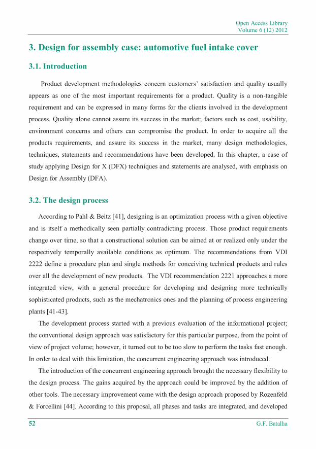
Open Access Library Volume 6 (12) 2012 52 G.F. Batalha 3. Design for assembly case: automotive fuel intake cover 3.1. Introduction Product development methodologies concern customers’ satisfaction and quality usually appears as one of the most important requirements for a product. Quality is a non-tangible requirement and can be expressed in many forms for the clients involved in the development process. Quality alone cannot assure its success in the market; factors such as cost, usability, environment concerns and others can compromise the product. In order to acquire all the products requirements, and assure its success in the market, many design methodologies, techniques, statements and recommendations have been developed. In this chapter, a case of study applying Design for X (DFX) techniques and statements are analysed, with emphasis on Design for Assembly (DFA). 3.2. The design process According to Pahl & Beitz [41], designing is an optimization process with a given objective and is itself a methodically seen partially contradicting process. Those product requirements change over time, so that a constructional solution can be aimed at or realized only under the respectively temporally available conditions as optimum. The recommendations from VDI 2222 define a procedure plan and single methods for conceiving technical products and rules over all the development of new products. The VDI recommendation 2221 approaches a more integrated view, with a general procedure for developing and designing more technically sophisticated products, such as the mechatronics ones and the planning of process engineering plants [41-43]. The development process started with a previous evaluation of the informational project; the conventional design approach was satisfactory for this particular purpose, from the point of view of project volume; however, it turned out to be too slow to perform the tasks fast enough. In order to deal with this limitation, the concurrent engineering approach was introduced. The introduction of the concurrent engineering approach brought the necessary flexibility to the design process. The gains acquired by the approach could be improved by the addition of other tools. The necessary improvement came with the design approach proposed by Rozenfeld & Forcellini [44]. According to this proposal, all phases and tasks are integrated, and developed
Transcript of 3. Design for assembly case: automotive fuel intake cover · • Lucas DFA Method: “The Lucas DFA...
Open Access Library Volume 6 (12) 2012
52 G.F. Batalha
3. Design for assembly case: automotive fuel intake cover
3.1. Introduction
Product development methodologies concern customers’ satisfaction and quality usually
appears as one of the most important requirements for a product. Quality is a non-tangible
requirement and can be expressed in many forms for the clients involved in the development
process. Quality alone cannot assure its success in the market; factors such as cost, usability,
environment concerns and others can compromise the product. In order to acquire all the
products requirements, and assure its success in the market, many design methodologies,
techniques, statements and recommendations have been developed. In this chapter, a case of
study applying Design for X (DFX) techniques and statements are analysed, with emphasis on
Design for Assembly (DFA).
3.2. The design process
According to Pahl & Beitz [41], designing is an optimization process with a given objective
and is itself a methodically seen partially contradicting process. Those product requirements
change over time, so that a constructional solution can be aimed at or realized only under the
respectively temporally available conditions as optimum. The recommendations from VDI
2222 define a procedure plan and single methods for conceiving technical products and rules
over all the development of new products. The VDI recommendation 2221 approaches a more
integrated view, with a general procedure for developing and designing more technically
sophisticated products, such as the mechatronics ones and the planning of process engineering
plants [41-43].
The development process started with a previous evaluation of the informational project;
the conventional design approach was satisfactory for this particular purpose, from the point of
view of project volume; however, it turned out to be too slow to perform the tasks fast enough.
In order to deal with this limitation, the concurrent engineering approach was introduced.
The introduction of the concurrent engineering approach brought the necessary flexibility to
the design process. The gains acquired by the approach could be improved by the addition of
other tools. The necessary improvement came with the design approach proposed by Rozenfeld
& Forcellini [44]. According to this proposal, all phases and tasks are integrated, and developed

Design for X – design for excellence
3. Design for assembly case: automotive fuel intake cover 53
Figure 3.1. Information flow according to Rozenfeld [44]
in parallel, one complementing the other as in a concurrent engineering process (Figure 3.1).
Based on Rozenfeld & Forcellini [44] proposition, a customization was performed in order to
make the development process clearer and more agile, due to the nature of the product and the
development team itself.
3.2.1. Design for assembly definitions
The requirements established during the informational phase of the design process are
associated to correspondent Df-X using keywords. The relation between requirement – DFX is
set on a Decision Make Matrix, in which each requirement was set against the Df-X
statements. The Df-X statements were based on the literature [46-48] and on the development
team’s experiences.
The Decision Make Matrix is a normalizer taking as a base the highest value from the
columns. The normalization allowed setting a hierarchy for the Df-Xs, or which had more
influence over the design process. The keywords matrix was constantly updated all along the
design process.
The main Df-Xs considered are listed below, and the 10 listed are those with more
influence over the design process:

Open Access Library Volume 6 (12) 2012
54 G.F. Batalha
• Design for Manufacturing – DfM;
• Design for Assembly – DfA;
• Design for Disassembly – DfD;
• Design for Maintainability – DfM;
• Design for Reliability – DfRl;
• Design for Safety – DfSt;
• Design for Usability – DfU;
• Design for Cost – DfC;
• Design for Quality – DfQ;
• Design for Recycling – DfRc.
Despite considering DFA since the first steps of the development process, its formal
application begins during the detailing phase of the project, and it runs in parallel with the
production process planning. It must be applied with other design techniques, sometimes
conflicting with the Design for manufacturing statements. The DFA technique aims mainly to
rationalize the assembly steps, by means of part reductions, part orientation, logic assembly
sequence, elimination or reduction of assembly inconsistencies and ambiguities.
Boothroyd [45] thinks that DFA must be specially employed through an intense interaction
during the initial phases of the design process. On the other hand, authors such as Pahl & Beitz
[41], Krause [43], Rozenfeld [44] and others see the DFA, and other DF-X statements, as part
of the Detailing Design phase, their full application must be considered since the beginning of
the design process as the requirements of the product request. Figure 3.2 shows the
introduction of DFA/DFM during the design process according to Boothroyd [45].
The Functional Design is one of the final steps of the Conceptual Design, it is when the
application of DFA, DFM, and most of the DF-X statements start, in order to evaluate which
conceptual solution is more suitable for being detailed. Special attention must be given to what
is available in terms of manufacture, materials, machines, tooling, inspection devices, assembly
facilities, financial resources, etc. and investments necessary to acquire the new requirements
introduced by the application of the DFA. Figure 3.3 compares the product development
process with and without the application of DFA, according to Boothroyd et al [50].
Figure 3.4 shows that for a product development to which DFA statements are applied, the
time spent in the conceptual design phase is higher than for the traditional approaches.

Design for X – design for excellence
3. Design for assembly case: automotive fuel intake cover 55
Figure 3.2. Introduction of DFA/DFM during the design process according to Boothroyd [45]
Figure 3.3. Comparison between the product development process with and without the
application of DFA [45]
On the other hand, the total amount of time for development is lower; due to the reduction of in
re-design needs. Also, the application of DFA assures cost reduction.

Open Access Library Volume 6 (12) 2012
56 G.F. Batalha
Figure 3.4. Functional analysis model of typical hand-held stapler. After D. L. Mann
3.2.2. DFA analysis - statements and rules
The DFA analysis works based on a methodology, structured on a series of statements,
rules and basic principles. The method guides the design time at the problems identification,
and sets a series of predefined solutions which stimulates news ones, in order to improve the
assembly requirements of the product. The tree main DFA methods are described below, and
this development is focused on the Lucas Method.
• Hitachi Method: “The Hitachi Assemblability Evaluation Method (AEM)”;
• Boothroyd & Dewhurst Method: “The B&D - DFA Evaluation Method”;
• Lucas DFA Method: “The Lucas DFA Evaluation Method”.

Design for X – design for excellence
3. Design for assembly case: automotive fuel intake cover 57
3.2.2.1. The Lucas method
Although the Boothroyd-Dewhurst method is more used, it is based on the analysis of time
for each of the handling and insertion motions. This analysis allows the construction of data
tables, and the accuracy resulting from the evaluation of these tables depends on the amount of
data compiled at a particular assembly plant. The Lucas DFA method was developed in the 1980s
by the Lucas Corp. in the U.K., in cooperation with Hull University. Unlike the Boothroyd-
Dewhurst method, the Lucas method is based on a "point scale" which gives a relative measure of
assembly difficulty. The method is based on three separate and sequential analyses. The basic
steps of the Lucas method are described as part of the Assembly Sequence Flowchart (ASF):
• Specification;
• Design;
• Assembly functional analysis, which is the 1st Lucas analysis; it provides feedback to the
Design process (step b) in order to eliminate/minimize assembly conflicts.
• Feeding analysis, which is the second Lucas analysis
• Fitting analysis, which is the third Lucas analysis
• Assessment
• Feedback of the Design process, step 2, in order to eliminate or minimize assembly
problems.
The assembly sequence flowchart penalizes each assembly problem of the detailed design.
These penalties are used to calculate three assembly indexes, set as measures of performance –
MOPs. This allows a part number reduction, and involves a full dimensional and geometrical
analysis of each part, or sub-assembly involved in the assembly process [52].
3.2.2.2. Assembly functional analysis
In the Assembly functional Analysis, all the parts are separated into two groups, A and B.
All the functional parts which compromise the product performance and specifications are set
in the A group. The parts which are not related with the primary specification, or perform a
secondary role, as fixture, connecting cables and others usages, are set in the B group. In this
step, the efficiency index, one of the MOPs is calculated, and it must exceed 60% [51].
%100)(
xBA
AEI
+
=
(3.1)

Open Access Library Volume 6 (12) 2012
58 G.F. Batalha
3.2.2.3. Feeding analysis
The feeding analysis will depend on the form of assembly, manual or automatic. For
manual assembly, a feeding analysis will give a cost-related rate for each part. For automatic
assembly, the rate comes from an appropriate table with cost values as a function from the
tools used. Some of the rates from the tables will generate a Feeding Index for each part. The
Feeding Index value is not higher than 1.5, if a design change occurs, it implies corrections at
not only at process bur also at the workpiece, so the change must be reflected at the final
component. From the Feeding Index of each part, a Feeding Ratio can be calculated, the
second of the MOP, and its ideal value must be around 2.5 [51].
GroupAinPartsofNumber
IndexFeedingRatioFeeding
∑=
(3.2)
The increase in the EI value means that the number of parts in the B group of a project must
be reduced. Parts in the A group, with high value, which strong influence the Feeding Ratio,
must be modified in order to diminish its values [52].
3.2.3. Fitting Analysis
The fitting analysis is calculated in the same way as the feeding analysis. The goal is a
fitting index of 1.5 for each assembly. Usually, a greater variance can be observed in the fitting
indexes than in the feeding indexes. A fitting ration of 2.5 is desired.
ComponentsEssentialofNumber
IndexFittingRatioFitting
∑=
(3.3)
3.2.4. Manufacturing Analysis
The Manufacturing Analysis is the last part of the Lucas method; it is used to calculate the
manufacturing cost of each component. The manufacturing cost influences the material and the
process selection by which the part will be made. Although it is based on cost estimation, and
not on the true cost value for each part, this method guides the design team by giving a relative
measure of manufacturing cost.
Mi = Rc .Pc. Mc (3.4)

Design for X – design for excellence
3. Design for assembly case: automotive fuel intake cover 59
and Rc and Mc in given by:
Rc = Cc . Cmp . Cmp .Cs . Ct . Cf (3.5)
Mc = V .Cmt .Wc (3.6)
where:
Rc − relative cost
Cc − complexity factor
Cmp − Material factor
Cs − Minimum section
Ct − tolerance factor or Cf = finish factor (whichever is greater)
Pc − processing cost
Mc − is the material cost
V − volume (mm3)
Cmt − material cost
Wc − waste coefficient
With this, the values are derived from specific tables or based on data collected in the plant.
3.3. Case study
The case study on DFA statements was accomplished to design an Automotive Fuel Intake
Cover from a Brazilian car manufacturer. Specific software developed by Iwaya [53], based on
the Lucas methodology, was used to support the application of the DFA statements and to
calculate the improvement indexes.
3.3.1. Product description
The Automotive Fuel Intake Cover, usually known as fuel cover, is shown in Figure 3.6.
Its function is to restrict the access to the fuel intake tube as well as to provide a visual
continuity for the outer side panel. Nowadays, fuel cover can be manufactured with polymers
(plastic) or steel; in this specific case, steel. The main objective of this analysis is to optimize
the number of parts, by reducing them to a minimum, without neglecting its primary
function.

Open Access Library Volume 6 (12) 2012
60 G.F. Batalha
Figure 3.6. Fuel cover placement in the car body
Figure 3.7. Exploded views of the fuel cover before the DFA analysis
An exploded view is shown in Figure 3.7. It is composed of 7 parts, each is described as
follows:
1. Rivet: allows the rotation of the fuel cover, before the DFA analysis union of 4, 5, 6 e 7
parts with part 3.
2. Double action torsion spring, keeps the fuels cover open during the feeding procedure, and
facilitates its closure.
3. Fixed hinge, fixes the fuel cover to the car body.

Design for X – design for excellence
3. Design for assembly case: automotive fuel intake cover 61
4. Movable hinge, allows connection between 5, 6 and 7 parts with 1;
5. External cover
6. Internal cover allows plastic lock attachment and increases fuel intake cover stiffness.
7. Plastic lock, allows electrical or manual locking of the fuel cover, depending on the car
version.
3.4. DFA analysis of the fuel cover
Before applying the DFA tools, it is essential to understand through the indicators, the
current status of the product being analysed. This understanding comes from the answers to
some questions suggested by the DFA software, which are primarily based on three groups of
analysis.
3.4.1. Assembly Functional Analysis
The Assembly Functional Analysis aims to promote a reflection regarding the functional
characteristics of the fuel cover as a system, mainly to understand the real functional need of each
part of the system. Figure 3.8 shows the main questions raised from the DFA software that must
be answered by the design team. This allows a better understanding of the relation between each
analysed part and the need of its rationalization or elimination. The reduction of the numbers of
parts of the system provides economic gains in terms of time, logistics, validation tests, and
others. Figure 3.8 shows the software [59] questioning for part 4, before DFA.
Figure 3.8. Assembly Functional Analysis before DFA of part 4

Open Access Library Volume 6 (12) 2012
62 G.F. Batalha
Figure 3.9. Feeding analysis for part 4 before DFA
3.4.2. Fuel cover - feeding analysis
Many aspects of the fuel cover handling are observed in the feeding analysis. Aspects such
as size and weight and their contribution to the handling and orientation are set. For each
answer, points are added to the rate index; in this specific feeding index, it was 1.3. Figure 3.9
shows the answers for part 4, before the DFA.
3.4.3. Fitting analysis
The Fitting Analysis covers aspects such as how easy are to perform the parts assemblies.
Factors such as part orientation during the assembly, assembly process flow, access, fastening,
fixture, clamping procedures, assembly view, and alignment and assembling forces are also
considered, adding a score to the final result. The fitting index in this analysis was 4.1, and the
specific answers for Part 4 are presented in Figure 3.10.
The performance index for all parts of the Fuel Intake Cover before de application of the DFA
methodology is shown in Table 3.1. The table cells with grey background indicate the unacceptable
indexes. All parts were spliced into two groups, were the A group will cover the functional parts,
and the B group will cover the secondary ones, and the efficiency index was calculated.

Design for X – design for excellence
3. Design for assembly case: automotive fuel intake cover 63
Figure 3.10. Fitting analysis for part 4
Table 3.1. Performance indexes for all parts of the fuel intake cover before DFA. Application
Part n# Handling Analysis Fitting Analysis
1 – rivet 1.0 7.2
2 – double action torsion spring 3.2 8.2
3 – fixed interface to the car body 1.3 4.1
4 – mobile interface 1.2 4.1
5 – external cover 1.3 3.3
6 – internal cover 1.3 3.3
7 – plastic lock 1.2 4.0
3.5. Analysis of the secondary parts
This analysis intends to review the need of each part in order to give the necessary
background to eliminate or promote the merging of unnecessary parts into a new one. The
current analysis shows that two parts were non-essentials, the double action torsion spring (part
n#2) and the internal cover (part n#6).
The main functions of the double action torsion spring are keeping the fuel cover open
during the feeding procedure, and facilitating its closure. Without it, it is impossible to keep the

Open Access Library Volume 6 (12) 2012
64 G.F. Batalha
cover open during refuelling, but the introduction of a load over the rivet, increasing the
friction into the bearing surface between the fixed and the mobile interface (parts n# 3 and 4),
allows the cover to be kept open, eliminating the need for the spring.
The internal cover has the structural reinforcement for the external cover as its main
function; it allows the union of the mobile interface and housing for the refuel locker. Some
changes in the concept and process were made, in order to eliminate the internal cover. The re-
designed Fuel Intake Cover after the DFA is shown in Figure 3.11. The main changes were:
• the mobile interface increases in order to allow the direct union with the external cover;
• the external cover thickness was increased to support the new structural requirement;
• the flange at the external cover was changed to allow electrical resistance spot weld;
• the plastic lock was changed for a new metal one assembled also by spot weld.
The process changes required called for reducing the number of parts is described as
follows:
• The hemming process was replaced with a spot weld.
• The riveting force over the rivet was changed to increase the friction between the mobile
and fixed interfaces.
Figure 3.11. Exploded view of the fuel intake cover after the DFA

Design for X – design for excellence
3. Design for assembly case: automotive fuel intake cover 65
3.6. Process analysis: improvement of the existing processes
The application of DFA statements requires a commitment not only from the design team,
but from the manufacturing engineering, which is responsible for the reduction of the handling
and adjustment indexes. Table 3.2 shows the new indexes for the product after DFA.
The improvements of the manufacturing processes were:
• the change from the hemming process to point welding at the mobile interface results in a
reduction of the adjustment index from 4.1 to 1.1;
• The handling and the adjustment indexes at the plastic lock / metallic lock changed from
1.2 to 1.0 and from 4.0 to 1.0 respectively, due to the change from manual assembly to
assembly with jigs during the welding process.
3.7. Comparative Analysis
A comparison between Tables 3.1 and 3.2 allows verifying the importance of using DFA
during a product development. Figure 3.12 shows the improvement of the fuel cover design by
the reduction of parts. The improvement over the manufacturing and the assembly processes,
make the fuel cover simpler, lighter, cheaper and with low assembly complexity. Full assembly
can be provided from supplier to automaker and applied directly to vehicle.
Table 3.2. Performance indexes for the fuel intake cover after the DFA application
Part n# Handling Analysis Fitting Analysis
1 – Rivet Pin 1.0 7.2
2 – Double action torsion spring --- ---
3 – Fixed hinge 1.3 3.4
4 – Movable hinge 1.2 1.1
5 – External cover 1.3 3.3
6 – Internal cover --- ---
7 – Plastic lock / metallic lock 1.0 1.0

Open Access Library Volume 6 (12) 2012
66 G.F. Batalha
Figure 3.12. Comparison of cover design before and after DFA
Table 3.3 provides a comparison in terms of number of parts, functional efficiency,
handling index and fitting index for the cover design before and after DFA.
Table 3.3. Performance indexes for all parts of the fuel intake cover after DFA application
Before DFA After DFA
Number of parts 7 5
Number of non-essential parts 2 0
Functional efficiency 71% 100%
Feeding ratio 2.1 1.2
Fitting ratio 6.8 3.2
3.8. Summary
DFA is a powerful tool for product development, since the conceptual phase of the product
development. An efficient application of its statements allow gains in terms of reduction in the
number of parts necessary, without compromising the functionality of the product, and also
allows a cost reduction, and in many cases an improvement in the product quality.

Design for X – design for excellence
3. Design for assembly case: automotive fuel intake cover 67
In spite of DFA methodology support, the design team experience is still a key factor for
tool success.
FEA Simulation was made after fuel intake cover DFA application keeping the same
structural performance.
An estimative cost analysis was made for this case study reaching 10% piece price saving.
Total tooling savings of 5% would be possible if DFA was applied on Conceptual Design
phase (Figure 3.1).