3 Atomic/Molecular-Level Simulations of Laser–Materials Interactions · 2009-12-15 · 3...
37
3 Atomic/Molecular-Level Simulations of Laser–Materials Interactions Leonid V. Zhigilei, Zhibin Lin, Dmitriy S. Ivanov, Elodie Leveugle, William H. Duff, Derek Thomas, Carlos Sevilla, and Stephen J. Guy Summary. Molecular/atomic-level computer modeling of laser–materials interac- tions is playing an increasingly important role in the investigation of complex and highly nonequilibrium processes involved in short-pulse laser processing and surface modification. This chapter provides an overview of recent progress in the develop- ment of computational methods for simulation of laser interactions with organic materials and metals. The capabilities, advantages, and limitations of the molecu- lar dynamics simulation technique are discussed and illustrated by representative examples. The results obtained in the investigations of the laser-induced generation and accumulation of crystal defects, mechanisms of laser melting, photomechanical effects and spallation, as well as phase explosion and massive material removal from the target (ablation) are outlined and related to the irradiation conditions and prop- erties of the target material. The implications of the computational predictions for practical applications, as well as for the theoretical description of the laser-induced processes are discussed. 3.1 Introduction Short-pulse lasers are used in a diverse range of applications, from advanced materials processing, cutting, drilling, and surface micro- and nano- structuring [1,2] to pulsed-laser deposition of thin films and coatings [3], laser surgery [4, 5], and artwork restoration [6, 7], and to the exploration of the conditions for inertial confinement fusion, with the world’s most energetic laser system being built at the National Ignition Facility at Lawrence Liver- more National Laboratory [8]. At the fundamental science level, short-pulse laser irradiation has the ability to bring material into a highly nonequilib- rium state and provides a unique opportunity to probe the material behavior under extreme conditions. In particular, optical pump-probe experiments have been used to investigate transient changes in the electronic structure of the irradiated surface with high (often subpicosecond) temporal resolution [9– 13], whereas recent advances in time-resolved X-ray and electron diffraction
Transcript of 3 Atomic/Molecular-Level Simulations of Laser–Materials Interactions · 2009-12-15 · 3...

3
Atomic/Molecular-Level Simulationsof Laser–Materials Interactions
Leonid V. Zhigilei, Zhibin Lin, Dmitriy S. Ivanov, Elodie Leveugle,William H. Duff, Derek Thomas, Carlos Sevilla, and Stephen J. Guy
Summary. Molecular/atomic-level computer modeling of laser–materials interac-tions is playing an increasingly important role in the investigation of complex andhighly nonequilibrium processes involved in short-pulse laser processing and surfacemodification. This chapter provides an overview of recent progress in the develop-ment of computational methods for simulation of laser interactions with organicmaterials and metals. The capabilities, advantages, and limitations of the molecu-lar dynamics simulation technique are discussed and illustrated by representativeexamples. The results obtained in the investigations of the laser-induced generationand accumulation of crystal defects, mechanisms of laser melting, photomechanicaleffects and spallation, as well as phase explosion and massive material removal fromthe target (ablation) are outlined and related to the irradiation conditions and prop-erties of the target material. The implications of the computational predictions forpractical applications, as well as for the theoretical description of the laser-inducedprocesses are discussed.
3.1 Introduction
Short-pulse lasers are used in a diverse range of applications, from advancedmaterials processing, cutting, drilling, and surface micro- and nano-structuring [1,2] to pulsed-laser deposition of thin films and coatings [3], lasersurgery [4, 5], and artwork restoration [6, 7], and to the exploration of theconditions for inertial confinement fusion, with the world’s most energeticlaser system being built at the National Ignition Facility at Lawrence Liver-more National Laboratory [8]. At the fundamental science level, short-pulselaser irradiation has the ability to bring material into a highly nonequilib-rium state and provides a unique opportunity to probe the material behaviorunder extreme conditions. In particular, optical pump-probe experiments havebeen used to investigate transient changes in the electronic structure of theirradiated surface with high (often subpicosecond) temporal resolution [9–13], whereas recent advances in time-resolved X-ray and electron diffraction

44 L.V. Zhigilei et al.
techniques [14–22] provide an opportunity to directly probe the ultrafastatomic dynamics in laser-induced structural transformations. Further opti-mization of experimental parameters in current applications, the emergenceof new techniques, and interpretation of the results of probing the tran-sient atomic dynamics in materials and at surfaces can be facilitated bycomputational modeling of laser–materials interactions.
One of the main challenges in the computational description of short-pulselaser interactions with materials is presented by the complex multiscale char-acter of the cascade of interrelated processes triggered by the laser excitation.These processes, schematically illustrated in Fig. 3.1, include laser excitationof optically active states in the target material (electronic or vibrational,linear or nonlinear/multiphoton), relaxation/thermalization of the absorbedlaser energy (electron–phonon energy transfer, intramolecular and intermolec-ular vibrational equilibration, nonthermal atomic dynamics), active structuraland phase transformations occurring in the high-temperature/high-pressureregion of the laser energy deposition (melting/denaturation/charring, gen-eration of crystal defects, fracture/spallation, explosive boiling, and surfacevaporization), as well as long-term evolution of multicomponent ablationplume (evaporation/condensation of clusters, chemical and ionization reac-tions). Computer modeling of this diverse range of processes is challengingand requires a combination of different models/techniques.
The description of the effect of the electronic excitation on the materialproperties is typically performed by means of computationally expensive elec-tronic structure calculations, e.g., [23–36]. Simulations based on electronicstructure calculations provide information on the changes in the interatomicbonding and the ultrafast atomic dynamics induced by the electronic excita-tion. The size of the systems used in electronic structure calculations, however,is typically limited to several hundreds of atoms and does not allow for arealistic representation of the transition from the electronic excitation to thecollective atomic dynamics responsible for the structural transformations inthe irradiated material.
Continuum-level simulations, on the other hand, are often used to studythe laser heating, melting, evaporation, and ablation on realistic, experimen-tal time and length scales. The most straightforward and computationallyefficient continuum approach is based on the solution of a set of partial dif-ferential equations describing the laser energy deposition and evolution oftemperature in the irradiated target. Various descriptions of melting, reso-lidification, surface vaporization, and ablation can be incorporated into suchmodels, albeit at a rather simplified level. In particular, laser melting andresolidification are often described with a phase-change model based on anassumption of local equilibrium at the solid–liquid interface (heat-flow limited,interface kinetics formulated within the framework of the Stephan problem),e.g., [37–39], or using a kinetic equation relating the interface velocity tothe interface temperature, e.g., [40–44]. The latter nonequilibrium kineticdescription has been shown to be necessary for subnanosecond pulses, when

3 Atomic/Molecular-Level Simulations of Laser–Materials Interactions 45
Fig. 3.1. Schematic representation of processes involved in short-pulse laserinteractions with materials
a fast thermal energy flow to/from the liquid–solid interface creates condi-tions for significant overheating/undercooling of the interface [43, 44]. Thematerial removal from the target can be incorporated into continuum mod-els in the form of surface or volumetric vaporization models, e.g., [45–49],

46 L.V. Zhigilei et al.
whereas the expansion of the vaporized plume is commonly described by solv-ing gas dynamics equations, e.g., [45–49] or using the Direct Simulation MonteCarlo (DSMC) technique, e.g., [50–55]. Hydrodynamic computational modelsbased on multiphase equations-of-state have also been used for simulation oflaser melting, spallation, and ablation [56–62]. The empirical equations-of-state provide a powerful framework for the description of the evolution ofthe thermodynamic parameters of the material (temperature, pressure, den-sity, internal energy), as well as the conditions for the laser-induced phasetransitions.
The common strength of the continuum models is in their computationalefficiency and the ability to simulate laser-induced processes at experimentaltime and length scales. The highly nonequilibrium nature of the processesinduced in the target material by the fast laser energy deposition, however,is challenging some of the basic assumptions of the continuum descriptionsthat are commonly designed based on the equilibrium material behavior andproperties. Although incorporation of kinetic models and metastable states,e.g., [43, 44, 60, 61], is possible within the continuum approach, the predictivepower of the models is limited by the necessity to make a priori assump-tions on the mechanisms and kinetics of all the processes that may takeplace during the simulation. The investigation of the generation of crys-tal defects and microscopic mechanisms of laser melting, nucleation andgrowth of voids in photomechanical spallation, the characteristics of theexplosive volume ablation and the parameters of the ejected multicomponentand multiphase ablation plume is difficult if not impossible with continuummodels.
In a situation where the continuum modeling of laser–materials interac-tions is hindered by the complexity and the highly nonequilibrium natureof the phenomenon, the classical molecular dynamics (MD) computer simu-lation technique has emerged as a promising alternative approach, which iscapable of providing atomic-level insights into the laser-induced processes. Aquickly expanding range of applications of MD simulations includes investiga-tions of laser-induced thermoelastic deformation, melting, and resolidification[63–74]; photomechanical damage and spallation [65, 68, 70, 75–82]; as well aslaser ablation of various material systems [70, 78, 79, 83–115].
In the remaining part of this chapter, the capabilities and limitations ofMD simulations of laser–materials interactions are discussed and illustratedby the results obtained in several recent computational studies. The basicideas of the classical MD method and some of the recent developments ofcomputational methodology that enable simulations of laser interactions withmolecular systems and metals are presented next, in Sect. 3.2. Some of theresults obtained in MD simulations of laser-induced generation of crystaldefects, melting, photomechanical spallation, and ablation are discussed inSect. 3.3. Finally, in Sect. 3.4, some of the promising directions for futurecomputational exploration are discussed.

3 Atomic/Molecular-Level Simulations of Laser–Materials Interactions 47
3.2 Molecular Dynamics Method for Simulationof Laser–Materials Interactions
In this section, we start from a brief introduction to the classical MD methodand highlight the advantages and limitations of the MD technique with respectto addressing research questions relevant to laser ablation and laser material-processing applications. The MD models developed for simulation of laserinteraction with molecular systems and metals are presented next, followedby a discussion of the boundary conditions that can provide a realistic descrip-tion of the energy dissipation from the absorption region to the bulk of thetarget.
3.2.1 Molecular Dynamics Method
Molecular dynamics (MD) is a computer simulation technique that allowsone to predict the time evolution of a system of interacting particles (atoms,molecules, granules). A detailed discussion of this method and the areas of itsapplicability can be found in several books devoted to atomistic simulationtechniques, e.g., [116,117]. Briefly, MD allows one to follow the evolution of asystem of N particles in time by solving a set of classical equations of motionfor all particles in the system,
mid2ri
dt2= Fi, i = 1, 2, . . . , N, (3.1)
where mi and ri are the mass and position of a particle i and Fi is the forceacting on this particle due to the interaction with other particles in the system.The force acting on the ith particle at a given time can be obtained from theinterparticle interaction potential U(r1, r2, r3, . . . , rN ) that, in general, is afunction of the positions of all the particles:
Fi = −∇iU (r1, r2, r3, . . . , rN ) . (3.2)
Once the initial conditions (initial positions and velocities of all particles inthe system) and the interaction potential are defined, the equations of motion,(3.1), can be solved numerically. The result of the solution is the trajectories(positions and velocities) of all the particles as a function of time, ri(t),vi(t),which is the only direct output of an MD simulation. From the trajectoriesof all particles in the system, one can easily calculate the spatial and timeevolution of structural and thermodynamic parameters of the system. Forexample, the atomic-level analysis of the development of the defect structuresor phase transformations can be performed and related to the changes intemperature and pressure in the system.
The main strength of the MD method is that the only input in the modelis the function describing the interparticle interaction, U(r1, r2, r3, . . . , rN ),

48 L.V. Zhigilei et al.
and no assumptions are made about the character of the processes understudy. This is an important advantage that makes the MD method to becapable of discovering new physical phenomena or processes in the course of a“computer experiment.” Moreover, unlike real experiments, the analysis of fastnonequilibrium processes in MD simulations can be performed with unlimitedatomic-level resolution, providing complete information on the phenomena ofinterest. The predictive power of the MD method, however, comes at a priceof a high computational cost, which imposes severe limitations on the timeand length scales accessible for the simulation. The record length-scale MDsimulations of systems containing more than 1011 atoms (micron-size cubicsamples) have been performed with the use of thousands of processors on oneof the world’s largest supercomputers [118], whereas long time-scale (up tohundreds of microseconds) simulations of protein folding have been performedthrough distributed computing [119].
The limitations on the time- and length scales that are accessible for MDsimulations present a serious challenge for the modeling of laser-induced pro-cesses that typically involve a collective motion of a large number of atomsor molecules in the surface region of the irradiated target. Moreover, sincethe electrons and quantum effects are not explicitly included in the classicalMD, the optical properties of the irradiated material cannot be obtained inthe course of the simulation, but have to be assumed in advance and pro-vided as input to the model. Thus, the design of novel approaches aimed atextending the time- and/or length-scales of MD simulations and incorporat-ing a description of the laser excitation into the MD model is required foran adequate modeling of laser–materials interactions. Two examples of com-putational models developed for MD simulations of laser interactions withmolecular systems and metals are discussed next, in Sects. 3.2.2 and 3.2.3.
3.2.2 Coarse-Grained MD Model for Simulationof Laser Interactions with Molecular Systems
In an atomic-level MD model, a typical small molecule or a monomer unitcan include tens of atoms, and a time-step of the integration of the equationsof motion of 0.1 fs or smaller must be used to follow high-frequency atomicvibrations. In order to overcome the limitations of the atomistic MD modeland to address collective processes responsible for laser-induced material mod-ification or ablation, a coarse-grained “breathing sphere” MD model has beendeveloped [98, 101].
The breathing sphere model assumes that each molecule can be representedby a single particle, Fig. 3.2a. The parameters of interparticle interaction arechosen to approximately reproduce the physical properties of a moleculartarget. The equilibrium distance in the interparticle potential is defined asthe distance between the edges of the spherical particles rather than theircenters, Fig. 3.2c. This choice of equilibrium distance is based on the physical

3 Atomic/Molecular-Level Simulations of Laser–Materials Interactions 49
Fig. 3.2. Schematic representation of the approximations used in the design ofcoarse-grained breathing sphere (a) and bead-and-spring (b) MD models. Potentialof intermolecular interaction in the breathing sphere model is shown in (c), whereR0
i and Ri are the equilibrium and instantaneous radii of the particle i; d0 and rsij
are the equilibrium and instantaneous distances between the edges of the sphericalparticles. The radii of the breathing spheres, Ri, are dynamic variables for whichequations of motion are solved during the simulation. Vibrational spectrum of anorganic solid represented by the breathing sphere model and the vibrational peakcorresponding to the internal breathing mode are shown in (d). Schematic sketchof a simulation setup for modeling of laser ablation of a 3wt.% polymer solution isshown in (e). The polymer chains are shown in light grey color and are superimposedon top of the image of matrix molecules shown in the background. Figures shown in(c) and (d) are from [98] and the image in (e) is from [113]
concept that the sublimation or cohesive energy of an organic solid is governedprimarily by the interactions among atoms on the outside of the molecule.This representation of intermolecular interactions allows an easy means ofsimulating multicomponent molecular systems [98, 102,105,106].
In order to simulate molecular excitation by photon absorption and vibra-tional relaxation of the excited molecules, an additional internal degree offreedom is attributed to each molecule. The internal degree of freedom, orbreathing mode, is implemented by allowing the particles to change their sizes.In the case of UV laser irradiation, the breathing mode can be considered asthe recipient of the energy released by an internal conversion from electroni-cally excited states. The parameters of a potential function attributed to theinternal motion control the characteristic frequency of the breathing mode,Fig. 3.2d; and, as a result, define the rate of the conversion of the internalenergy of the molecules excited by the laser to the translational and internalmotions of the surrounding molecules. The rate of the vibrational relaxationof excited molecules is an input parameter in the model and can be either

50 L.V. Zhigilei et al.
estimated from pump-probe experiments [120, 121] or obtained in atomistic[122] or ab initio [123] MD simulations.
The laser irradiation is simulated by vibrational excitation of moleculesthat are randomly chosen during the laser pulse duration within the pene-tration depth appropriate for a given wavelength. Vibrational excitation ismodeled by depositing a quantum of energy equal to the photon energy intothe kinetic energy of internal motion of a given molecule. An alternative resultof the photon absorption, photofragmentation of the excited molecule intofragments that can subsequently participate in chemical reactions, can alsobe reproduced within the model [78, 106, 111]. A description of the processesleading to the ionization of molecules in laser ablation has recently been incor-porated into the breathing sphere model and the mechanisms responsible forthe ion formation in matrix-assisted laser desorption ionization (MALDI) massspectrometry technique have been explored [112].
In order to enable simulations of laser interaction with polymer solutions[107, 113, 114, 124–126], the breathing sphere model has recently been com-bined with the bead-and-spring model, commonly used in polymer modeling[127]. In the bead-and-spring model, schematically illustrated in Fig. 3.2b, the“beads” representing the functional groups of a polymer molecule (monomers)are connected by anharmonic springs with strengths appropriate for chemicalbonding. An example of the computational setup used in simulations of laserablation of polymer solutions [113,124,125] is given in Fig. 3.2e.
Since both the breathing sphere model and the bead-and-spring modeladopt a coarse-grained representation of molecules, in which each moleculeor monomer unit is represented by a single particle, the system size can besufficiently large to reproduce the collective dynamics in a molecular systemleading to laser ablation or damage. Moreover, since explicit atomic vibrationsare not followed, the time-step in the numerical integration of the equationsof motion can be much longer and the dynamics in the irradiated samplecan be followed for as long as nanoseconds. The limitations of the breath-ing sphere model are related to the approximation of all the internal degreesof freedom of a molecule by one internal mode. The rates of intermolecularenergy transfer cannot be studied within the model, but have to be specifiedthrough the input parameters, as discussed earlier. The accuracy in quan-titative description of the thermodynamic and transport properties of thematerials represented at the coarse-grained level is limited, and the model isappropriate for investigation of general, rather than material-specific, charac-teristics of the laser-induced processes. A smaller number of degrees of freedomin the model system should also be taken into account when performing aquantitative comparison with experimental data, e.g., of the threshold fluencefor the ablation onset [79, 103].

3 Atomic/Molecular-Level Simulations of Laser–Materials Interactions 51
3.2.3 Combined Continuum-Atomistic Model for Simulationof Laser Interactions with Metals
In metals, laser light is absorbed by the conduction band electrons. Thedeposited energy quickly, within femtoseconds, is equilibrated among the elec-trons and, more slowly, is transferred to the lattice vibrations. The laterprocess is controlled by the strength of the electron–phonon coupling andcan take from fractions of a picosecond to several tens of picoseconds. Finally,a thermal equilibrium is established between the electrons and phonons, andthe conventional heat conduction equation can be used to describe the heatflow into the bulk of the irradiated target. The classical MD technique doesnot include an explicit representation of electrons and, therefore, cannot beused, in its conventional formulation, for simulation of the laser light interac-tion with the target material, the relaxation/thermalization of the absorbedlaser energy, and the fast electron heat conduction to the bulk of the irradiatedtarget.
To enable atomic-level simulations of processes involving electronic exci-tations of metal targets by short-pulse laser irradiation (or energetic ion bom-bardment), several computational approaches have been proposed [64, 65, 89,108,128,129]. In particular, the model described in [65] combines classical MDmethod with a continuum description of the laser excitation and subsequentrelaxation of the conduction band electrons, based on the so-called two-temperature model (TTM) [130]. In the original TTM, the time evolution ofthe lattice and electron temperatures, Tl and Te, is described by two couplednonlinear differential equations. In the combined TTM–MD method, schemat-ically illustrated in Fig. 3.3, MD partially substitutes the TTM equation forthe lattice temperature. The diffusion equation for the electron temperatureis solved by a finite difference method simultaneously with MD integration ofthe equations of motion of atoms. The electron temperature enters a couplingterm that is added to the MD equations of motion to account for the energyexchange between the electrons and the lattice. The MD method is used onlyin the very surface region of the target, where active processes of laser melting,resolidification, and/or ablation take place, whereas the diffusion equation forthe electron temperature is solved in a much wider region affected by the ther-mal conduction. A special pressure-transmitting boundary condition appliedat the bottom of the MD part of the computational region, as well as theperiodic boundary conditions imposed in the directions parallel to the sur-face, is briefly discussed later, in Sect. 3.2.4. In the part of the computationalcell beyond the MD region (left part in Fig. 3.3), the energy exchange betweenthe electrons and the lattice is described by the conventional TTM.
The hybrid continuum-atomistic model, briefly described above, combinesthe advantages of TTM and MD methods. TTM provides an adequate descrip-tion of the laser energy deposition into the electronic system, the energyexchange between the electrons and phonons, and the fast electron heat

52 L.V. Zhigilei et al.
Fig. 3.3. Schematic representation of the combined continuum-atomistic modelfor simulation of laser interaction with a metal target. The evolution of electrontemperature, Te, is described by a nonlinear differential equation, whereas the atomicmotions are described by the MD method with an additional term, ξmiv
Ti , added to
the ordinary MD equations of motion to account for the electron–phonon coupling.Spatial discretization in the continuum model (typically ∼1 nm) and size of theatomistic region are not drawn to scale. The cells in the finite difference discretizationare related to the corresponding volumes of the MD system and the local latticetemperature, T cell
l , is defined for each cell from the average kinetic energy of thermalmotion of atoms. Thermal velocity of an atom is defined as vT
i = vi − vc, wherevi is the actual velocity of an atom i and vc is the velocity of the center of massof a cell to which the atom i belongs. A Gaussian temporal profile, S (z, t), is usedto describe the laser excitation of the conduction band electrons. The expansion,density variations and, at higher fluences, disintegration of the irradiated targetpredicted in the MD part of the model are accounted for in the continuum part ofthe model. A complete description of the combined TTM–MD model is given in [65]
conduction in metals, whereas the MD method is appropriate for simulationof rapid nonequilibrium phase transformations, damage, and ablation.
The results of the recent investigation of the electron temperature depen-dence of the electron–phonon coupling factor G, the electron heat capacity Ce,and the heat conductivity Ke (thermophysical material properties included inthe TTM equation for the electron temperature, see Fig. 3.3) suggest thatthe effect of the thermal excitation from the electron states below the Fermilevel should be accounted for in a model aimed at a quantitative descriptionof the laser-induced processes in metals [131–134]. Indeed, a computationalanalysis based on the first-principles electronic structure calculations of theelectron density of states reveals that these thermophysical materials prop-erties are very sensitive to details of the electronic structure of the materialand can exhibit large deviations (up to an order of magnitude) from thecommonly used approximations of a linear temperature dependence of theelectron heat capacity and a constant electron–phonon coupling. A number ofpractically important characteristics of the laser–material interactions, suchas the threshold fluences for the onset of melting and ablation, the strengthof the laser-induced stress wave, the emission of electrons from the irradiated

3 Atomic/Molecular-Level Simulations of Laser–Materials Interactions 53
surface, and the depth of the melting and/or heat-affected zone, can all besignificantly altered by the transient changes of the thermophysical propertiesoccurring during the time of electron–phonon equilibration. It has been shown,in particular, that incorporation of the new electron temperature dependencesof the thermophysical properties [133, 134] into TTM or TTM–MD modelsresults in an improved agreement between the computational predictions andexperimental observations [20, 131, 132,135].
In the examples considered in Sect. 3.3 of this chapter, the interatomicinteractions in the MD part of the TTM–MD model are described by theembedded atom method (EAM) potential [136,137] that provides a computa-tionally simple but rather realistic description of bonding in metallic systems.In particular, the functional form and parameters of the EAM potential forNi, Al, Cu, and Au are given in [138], whereas a recently developed potentialfor Cr is described in [74].
3.2.4 Boundary Conditions: Pressure Wavesand Heat Conduction
The severe limitations on the length scales in MD method make it impossibleto directly simulate processes occurring within the whole laser spot. For a laserspot of 10–100 μm in diameter and an ablation depth of 10–100 nm, one canestimate that the number of molecules/atoms ejected from an irradiated tar-get in a single laser shot is in the range from tens of billions to trillions. Thesenumbers are much beyond the limits of the MD simulation technique (seeSect. 3.2.1). In this situation, the MD computational cell is typically assumedto represent a local volume within the laser spot and the material responseto local laser energy deposition is investigated, as schematically shown inFig. 3.4. The periodic boundary conditions in the lateral directions, parallelto the surface of the target, are used in this case to reproduce the interactionof molecules or atoms in the MD computational cell with the surroundingmaterial. This approach is appropriate for a situation in which the laser spotdiameter is much larger than the depth of the laser energy deposition, sothat any effects related to the lateral variations of the irradiation and thermalconditions can be neglected and the simulated part of the system remainslaterally confined by the surrounding material during the time of the simula-tion. The information on the material ejection from the whole laser spot canthen be obtained by integrating over the results of a series of MD simulationsperformed for a range of “local fluences,” Fig. 3.4.
In the direction normal to the surface of the irradiated target, a free bound-ary condition, allowing for a natural expansion of the irradiated target andthe ejection of atoms, molecules, and clusters in laser ablation, is the naturalchoice for the irradiated (top) surface. More complex boundary conditions,however, accounting for the thermal conduction and pressure wave propaga-tion from the absorption region deeper into the bulk of the target, have to beused at the bottom of the MD computational cell.

54 L.V. Zhigilei et al.
Fig. 3.4. Schematic illustration of the local areas represented in MD simulations oflaser ablation at different locations within a laser spot. Snapshots used in this figureare from simulations of laser interactions with a molecular target [78]
In order to evaluate the necessity for the introduction of the heat-conductive and pressure-transmitting boundary conditions, one can considercharacteristic times of the heat transfer and pressure wave propagation acrossa typical size of the MD computational cell, LMD ≈ 100 nm. The timescaleof the heat conduction across the computational cell can be evaluated asτth ≈ (
L2MD
)/ (2DT), where DT is the thermal diffusivity of the target mate-
rial. For molecular systems DT ≈ 10−7 m2 s−1, and the timescale of the heatconduction is τth ≈ 50 ns, much longer than the time-scale of a typical MDsimulation. In metals, however, the heat conduction, dominated by the elec-tron heat transport, is much larger, e.g., DT ≈ 10−4 m2 s−1 for gold. Thisyields τth ≈ 50 ps, a time that is shorter than the time needed for an adequatesimulation of laser-induced structural transformations. Therefore, we can con-clude that, while the effect of heat transfer through the bottom of a sufficientlylarge computational cell can be neglected in simulations of molecular systems,the boundary conditions in simulations of laser interactions with metals mustaccount for the heat conduction. The combined TTM–MD model, discussedin Sect. 3.2.3, provides a natural description of the electron heat conductionfrom the surface region of the target, represented with atomic-level resolution,to the deeper part of the target, represented at the continuum level, Fig. 3.3.Indeed, a seamless transition in the temperature field from the atomistic tothe continuum regions can be seen in Fig. 3.9 (Sect. 3.3.3), illustrating the evo-lution of temperature in a simulation performed for a bulk Ni target irradiatedwith a 1 ps laser pulse.

3 Atomic/Molecular-Level Simulations of Laser–Materials Interactions 55
The pressure waves, generated as a result of the relaxation of laser-inducedthermoelastic stresses and, above the threshold for the ablation onset, recoilpressure from the ejected material, present an additional challenge for sim-ulations of short-pulse laser–materials interactions. In order to simulate apropagation of the laser-induced pressure wave into the bulk of the sam-ple, the size of the MD computational cell should be increased linearly withthe time of the simulation. For times longer than a hundred of picoseconds,the size of the model required to follow the wave propagation becomes com-putationally prohibitive. If large computational cells are not used, however,artificial border effects can interfere with the simulation results, as both rigidand free boundary conditions lead to the complete reflection of the pressurewave [78, 82]. The free boundary condition at the bottom of the computa-tional cell is appropriate for simulations of laser interaction with free-standingfilms [65–68, 70–72, 75, 76, 82, 91], whereas the rigid boundary condition canbe related to experiments performed for a thin absorbing layer deposited ona hard substrate [139]. In most cases, however, we are interested in muchlarger systems for which the effect of the pressure wave reflection has to beavoided. To enable the simulations of laser interactions with bulk systems,special pressure-transmitting boundary condition based on an analytical eval-uation of the forces acting on atoms/molecules in the boundary region fromthe outer “infinite medium” has been developed [140,141]. The energy that iscarried away by the stress wave though the pressure-transmitting boundarycondition can be monitored, allowing for a control over the energy conser-vation in the model [69]. The nonreflecting boundary conditions have beensuccessfully used in simulations of laser melting, ablation, and damage fordifferent target materials in which both planar, e.g., [69,78–82,89,92,93,103–113] and spherical [142] pressure waves are generated. An illustration of thenonreflective propagation of the pressure wave from the atomistic to thecontinuum parts of the combined TTM–MD model can be seen in Fig. 3.9(Sect. 3.3.3).
3.3 Simulations of Laser-Induced Structuraland Phase Transformations
The MD method allows one to perform a detailed analysis of the laser-inducedprocesses in which thermodynamic parameters of the system can be correlatedwith microscopic dynamics at the atomic level. In this section, the ability ofthe MD method to provide insights into the mechanisms of laser–materialsinteractions is demonstrated by a representative set of recent computationalresults obtained in simulations of laser-induced generation of crystal defects,melting, photomechanical spallation, and ablation.

56 L.V. Zhigilei et al.
3.3.1 Generation of Crystal Defects
The understanding of the mechanisms and driving forces responsible forlaser-induced generation of crystal defects is important for the advancementof laser processing applications aimed at controlled modification of surfacemicrostructure. MD simulations are capable of providing detailed atomic-levelinformation on the elementary processes responsible for the generation andevolution of defect configurations in irradiated targets. To illustrate this capa-bility and highlight the sensitivity of the laser-induced defect structures to thetype of the crystal structure of the target, the results of simulations performedfor two metals with different crystal structures, body-centered cubic (bcc) Crand face-centered cubic (fcc) Ni, are discussed in this section.
The fast structural changes in a Cr target irradiated with a 200-fs laserpulse have been analyzed in [74] based on the results of TTM–MD simulations.The snapshots of atomic configurations taken at different times of a simula-tion performed at an absorbed fluence of 638 J m−2 (just above the thresholdfor surface melting) are shown in Fig. 3.5a. Only atoms that belong to theliquid phase or are located in the vicinity of crystal defects, are shown in thesnapshots, with all the atoms that have local atomic surroundings (and corre-sponding values of the potential energy) similar to the ones in the original bccstructure blanked. During the first 100 ps after the laser pulse, the irradiatedtarget experiences transient melting and epitaxial resolidification of a thin(up to 3 nm) surface layer, which shows up in Fig. 3.5a as a layer of red atomsat 50 ps and reduces to a plane composed of atoms located at the surface ofthe recrystallized target by the time of 100ps.
Another transient effect apparent from the snapshots shown in Fig. 3.5ais the appearance, expansion (up to 30 ps), retraction, and disappearance (by115 ps) of a complex pattern of atomic planes with elevated energy. Detailedanalysis of the atomic configurations reveals that these planes correspond tothe intrinsic stacking faults generated as a result of multiple internal shiftsalong {110} crystallographic planes by displacement vectors a/8 < 110 >(where a is the lattice parameter). The generation of the stacking faults isactivated by the rapid uniaxial expansion of the crystal in the direction normalto the irradiated surface. Calculations of the generalized stacking fault energysuggest, in agreement with earlier studies [143], that the intrinsic stackingfaults are unstable in an unstrained bcc crystal but can be stabilized by auniaxial expansion of the crystal. Indeed, the appearance of the stacking faultscorrelates with the lattice expansion associated with the initial relaxation ofthe laser-induced stresses. All stacking faults disappear by ∼115 ps, shortlyafter the laser-induced tensile stress wave leaves the surface region of thetarget [74].
The disappearance of the stacking faults makes the presence of a largenumber of vacancies clearly visible in the surface region of the target, e.g.,snapshot shown for 450ps in Fig. 3.5a. With the visualization method usedin Fig. 3.5a, where only atoms with elevated potential energy are shown, each

3 Atomic/Molecular-Level Simulations of Laser–Materials Interactions 57
Fig. 3.5. Snapshots of the surface regions of atomic configurations obtained inTTM–MD simulations of bcc Cr (a) and fcc Ni (b) targets irradiated with a shortpulse laser. The absorbed laser fluences and pulse durations are 638 Jm−2 and 200 fsfor Cr, and 645 J m−2 and 1 ps for Ni targets. The snapshots are shown down to thedepth of 20 nm below the level of the initial surface in (a) and for a region locatedbetween 30 and 60 nm below the level of the initial surface in (b). The atoms are col-ored according to their potential energies in (a) and the centrosymmetry parameterin (b), with atoms that belong to local configurations corresponding to the originalbcc (a) or fcc (b) structure blanked to expose crystal defects. Typical defect con-figurations marked in the snapshots are “A” – stacking fault with a displacementvector of a/8<110>, “B” – a vacancy, “C” – an interstitial in a <110>-dumbbellconfiguration, “D” – a four <111>-crowdion interstitial cluster, and “E” – a dislo-cation with a Burgers vector of a/2<110>, dissociated into two a/6<112> Shockleypartial dislocations connected by a stacking fault ribbon. The snapshots shown in(a) are from [74]
vacancy appears as a cluster of 14 atoms that includes the eight nearest neigh-bors and six second-nearest neighbors of the missing atom. The number ofvacancies observed in the top 5 nm surface region of the target at 450ps cor-responds to a very high vacancy concentration, more than 10−3 vacancies per

58 L.V. Zhigilei et al.
lattice site. The thermally activated generation of vacancy-interstitial pairsduring the laser-induced temperature spike serves as the initial source of thepoint defects. Due to the high mobility of self-interstitials, they quickly escapeto the melting front or the free surface of the target, leaving behind a largenumber of vacancies (only one individual interstitial and one cluster of fourinterstitials arranged in a mobile <111>-crowdion configuration can be iden-tified in a snapshot shown for 450ps in Fig. 3.5a). A significant number ofvacancies are also produced at the advancing solid–liquid interface during thefast resolidification process.
The strong temperature gradient created in the surface region of the tar-get by the short-pulse laser irradiation, and the associated ultrafast coolingrates exceeding 5× 10¹² K s−1 at the time of resolidification, provide the con-ditions for stabilization of the highly nonequilibrium vacancy concentration.Indeed, an analysis of the long-term evolution of the vacancy configuration,performed in [74], suggests that the average vacancy diffusion length duringtens of nanoseconds after the end of the TTM–MD simulation is very small,on the order of an interatomic distance. The configuration of mostly individ-ual vacancies observed at the end of the TTM–MD simulation is, therefore,unlikely to undergo any significant changes during the remaining part of thecooling process.
The processes responsible for the generation of crystal defects in fcc Nitarget exhibit both similarities and differences with the ones discussed abovefor bcc Cr target. The formation of vacancy-interstitial pairs followed by thefast escape of the interstitials is observed in both Ni and Cr targets andproceeds in a qualitatively similar manner. An important difference betweenthe simulations performed for the two materials is a massive generation ofpartial dislocations observed for Ni targets, e.g., Fig. 3.5b. This observationcan be related to the existence of stable low-energy stacking faults and 12close-packed {111} <110> slip systems with small resistance to the motion ofdislocations (low Peierls stress) in fcc crystals. Unlike the transient appearanceof the unstable stacking faults in Cr, the stacking faults left behind by the par-tial dislocations propagating from the melting front in the Ni target are stableand have relatively low energy (110 mJm−2 is predicted by the EAM Ni poten-tial, in a reasonable agreement with the experimental value of 125 mJm−2
[144]). Interactions between the dislocations propagating along the differentslip planes result in the formation of immobile dislocation segments (the so-called stair-rod dislocations) that, together with the fast cooling of the surfaceregion of the target, stabilize the dislocation configuration generated duringthe initial spike of temperature and thermoelastic stresses.
The supersaturation of the surface region of an irradiated target withvacancies, observed for both Ni and Cr targets, may result in the formation ofnanovoids and degradation of the mechanical properties of the surface regionof the target in the multipulse irradiation regime. The generation of crystaldefects may be, thus, related to the incubation effect, when the laser fluencethreshold for ablation/damage decreases significantly with increasing number

3 Atomic/Molecular-Level Simulations of Laser–Materials Interactions 59
of laser pulses applied to the same area, e.g., [145–149]. The high density ofvacancies generated in the surface region should also play an important rolein the redistribution of impurities or mixing/alloying in multicomponent orcomposite targets. The generation of dislocations and, in particular, disloca-tion reactions leading to the formation of immobile dislocation configurationsshould result in hardening of the surface region of the target.
3.3.2 Mechanisms and Kinetics of Laser Melting
Most of the methods of laser surface modification involve melting and sub-sequent resolidification of a surface region. It has been well established thatmelting starts at surfaces and internal crystal defects under minor superheat-ing conditions or even below the equilibrium melting temperature [150, 151].After heterogeneous nucleation of the liquid phase, the liquid–solid interfacepropagates into the bulk of the solid, precluding any significant superheat-ing and making observation of an alternative mode of melting, homogeneousnucleation in the bulk of a superheated crystal, difficult. The extremely highheating rates achievable with short-pulse laser irradiation, however, createthe conditions for competition between the heterogeneous and homogeneousmelting mechanisms and provide unique opportunities for the investigation ofthe kinetic limits of achievable superheating. Moreover, the emerging time-resolved electron and X-ray diffraction experimental techniques are capableof probing the transient atomic dynamics in laser melting with subpicosecondresolution [14–22]. The complexity of the fast nonequilibrium phase transfor-mation, however, hinders the direct translation of the diffraction profiles tothe transient atomic structures.
MD simulations are well suited for investigation of the ultrafast lasermelting phenomenon and are capable of providing detailed atomic-level infor-mation needed for a reliable interpretation of experimental observations. Inparticular, the kinetics and mechanisms of laser melting have been investi-gated in a series of TTM–MD simulations performed for Ni, Au, and Al thinfilms and bulk targets irradiated by short, from 200 fs to 150ps, laser pulses[65–72,109,132]. The relative contributions of the homogeneous and heteroge-neous melting mechanisms have been analyzed and related to the irradiationconditions. Except for the fluences close to the threshold for surface melt-ing, the heterogeneous melting (melting front propagation from the surface)is found to make very limited contribution to the overall melting process, withhomogeneous nucleation of multiple liquid regions being the dominant melt-ing mechanism [65,66,71]. This observation has been supported by the resultsof recent large-scale TTM–MD simulations aimed at establishing the maxi-mum velocity of the melting front propagation in metals [152]. A surprisingresult from this study is that the maximum velocity of the melting front justbelow the limit of the crystal stability against homogeneous melting is below3% of the speed of sound, more than an order of magnitude lower than com-monly assumed in interpretation of the results of laser melting experiments,

60 L.V. Zhigilei et al.
e.g., [10, 14, 153]. The relatively low maximum velocity of the melting front,revealed in the simulations, has direct implications for interpretation of theexperimental data on the kinetics of melting. For example, for thin 20-nm Aufilms used in recent time-resolved electron diffraction experiments [20,154], themelting time shorter than 70 ps would clearly point to the major contributionof the homogeneous nucleation to the melting process [71, 132].
A schematic map of the melting mechanisms shown in Fig. 3.6 can provideguidance in the analysis of the relative contributions of different processesto laser melting. The heterogeneous melting starts from the free surface(s)of the target as soon as the temperature exceeds the equilibrium meltingtemperature, Tm. The equilibrium melting temperature is changing with pres-sure according to the Clapeyron equation (increases with increasing pressurefor metals having positive volume change on melting). As discussed earlier,the melting front propagation is relatively slow and the surface region ofthe irradiated target can be easily overheated significantly above the equi-librium melting temperature, up to the limit of superheating shown by thedashed line in Fig. 3.6. The temperature of the maximum superheating, Ts, isdefined as a temperature at which melting starts within tens of picosecondsin a simulation performed for a perfect crystal with three-dimensional peri-odic boundary conditions (no external surfaces) under conditions of constanthydrostatic pressure. The values of the maximum superheating, (Ts–Tm) /Tm,predicted in MD simulations for different close-packed metals vary from 0.19to 0.30 [155] and are somewhat smaller, below 0.15, for bcc metals [74, 156].In the case of EAM Ni used in Fig. 3.6, the maximum superheating graduallyincreases from 0.21 to 0.25 as pressure increases from –5GPa to 10GPa.
In the area of the pressure–temperature field above the limit of superheat-ing (red area in Fig. 3.6), rapid nucleation and growth of liquid regions insidethe superheated crystal are responsible for the melting process. Note that thehomogeneous melting observed above the maximum superheating does notfollow the classical picture of a homogeneous phase transition – the nucle-ation and growth of well-defined spherical liquid regions. Rather, the meltingin this regime proceeds as a collapse of the lattice superheated above thelimit of its stability and takes place within just several picoseconds (severalperiods of atomic vibrations). Actually, the “classical” homogeneous meltinghas never been observed in laser melting simulations performed so far andthe image showing two compact liquid regions in Fig. 3.6 is taken from a sim-ulation of a slow heating of a crystal under well-controlled temperature andpressure conditions. Indeed, one can expect that the fast evolution of the tem-perature and pressure induced by short-pulse laser irradiation would readilyovershoot the narrow region close to the limit of superheating (shown by greencolor in Fig. 3.6) where the “classical” homogeneous melting may be expected.Moreover, the temperature of the onset of homogeneous melting (the limit ofsuperheating) can be significantly reduced by anisotropic lattice distortionsassociated with the relaxation of the laser-induced thermoelastic stresses [66].Above the limit of superheating, the melting happens so fast that there is no

3 Atomic/Molecular-Level Simulations of Laser–Materials Interactions 61
Fig. 3.6. Pressure/temperature conditions for equilibrium and nonequilibrium melt-ing observed in simulations of laser interactions with metal targets. Blue trianglescorrespond to the conditions of equilibrium melting obtained in liquid-crystal coex-istence simulations. Red squares connected by the black dashed line correspond tothe maximum overheating of a crystal observed in simulations performed with three-dimensional periodic boundary conditions and constant hydrostatic pressure. Theareas of the pressure–temperature field corresponding to the ultrafast homogeneousmelting above the limit of superheating, classical homogeneous melting by nucle-ation and growth of individual liquid regions, and heterogeneous melting by themelting front propagation from the surface are shown by red, green, and blue colors,respectively. The data points are calculated for the EAM Ni material
time for the system to minimize the interfacial energy for the rapidly evolvingliquid regions.
A typical picture of the homogeneous melting above the limit of superheat-ing is shown in Fig. 3.7, where the snapshots from a simulation of laser meltingof a 20nm Au film are shown along with the corresponding structure functions.The fluence used in this simulation is ∼75% above the fluence needed for thecomplete melting of a 20 nm Au film [71]. The small thickness of the film andthe fast electron energy transport in Au [65,71,132] result in the even distribu-tion of the electron temperature established shortly after the laser excitation.The electron–phonon energy transfer then leads to the increase of the latticetemperature. The lattice temperature exceeds the equilibrium melting tem-perature by more than 40% by the time of 6 ps, triggering a spontaneoushomogeneous nucleation of a large number of small liquid regions throughoutthe film and a rapid collapse of the crystalline structure within the subsequent3–4 ps (Ts ≈ 1.25Tm for the EAM Au). The visual analysis of the snapshotstaken during the melting process shows that by ∼6 ps the growth of liquidregions starts at two free surfaces of the film, where the kinetic energy barrier

62 L.V. Zhigilei et al.
Fig. 3.7. Structure functions calculated for atomic configurations generated in aTTM–MD simulation of laser melting of a 20-nm Au film, irradiated with a 200-fslaser pulse at an absorbed fluence of 92.5 J m−2. The corresponding snapshots ofatomic configurations are shown as insets in the plots, with the laser pulse directedfrom the right to the left sides of the snapshots. Atoms in the snapshots are col-ored according to the local order parameter [65] – blue atoms have local crystallinesurroundings and red atoms belong to the liquid phase. Zero time corresponds to aperfect fcc crystal at 300 K just before the laser irradiation. The effect of the ther-mal excitation of d-band electrons on the parameters of the TTM equation for theelectron temperature [133] is included in this simulation. The snapshots are fromRef. [132]
is absent for the nucleation of the liquid phase. However, due to the fast rateof the lattice heating, the propagation of the melting fronts from the freesurfaces of the film does not make any significant contribution to the overallmelting process.
The calculation of the diffraction profiles and density correlation functions[71,72] provides a direct connection between the results of MD simulations andtime-resolved diffraction experiments. The increasing amplitude of thermal

3 Atomic/Molecular-Level Simulations of Laser–Materials Interactions 63
atomic vibrations (Debye–Waller factor), as well as shifts and splittings ofthe diffraction peaks due to the thermoelastic deformation of the film prior tomelting, is found to be responsible for the initial decrease of the intensity of thediffraction peaks (from 0 to 6 ps in Fig. 3.7). The onset of the melting processat ∼6 ps leads to the complete disappearance of the crystalline diffractionpeaks by the time of 10 ps, Fig. 3.7.
The simulation illustrated in Fig. 3.7 is performed for the irradiation con-ditions similar to the ones used in recent time-resolved electron diffractionmeasurements performed for 20 nm Au films [20, 154]. The disappearance ofthe diffraction peaks corresponding to the crystal structure is found to takeplace between 7 ps and 10 ps after the laser pulse. This experimental obser-vation is in an excellent agreement with the simulation results illustrated inFig. 3.7. Note that this agreement has only been achieved by accounting forthe effect of the thermal excitation of d band electrons on the electron temper-ature dependence of the electron heat capacity and electron–phonon coupling[131–134] in the TTM–MD model. Earlier simulations, performed with thecommonly used approximations of the constant electron–phonon couplingfactor and the linear temperature dependence of the electron heat capacity,predict a much longer, ∼16 ps, delay time for the onset of melting [71, 132].This observation supports the importance of accounting for the effects relatedto the thermal excitation of lower band electrons [133] for realistic modelingof laser-induced processes.
3.3.3 Photomechanical Spallation
The fast energy deposition in short-pulse laser processing application notonly results in a sharp temperature rise in the surface region of the tar-get but, unavoidably, generates strong thermoelastic stresses that can playan important role in defining the characteristics of laser melting, genera-tion of crystal defects, and material ejection. The maximum values of thelaser-induced stresses and the contribution of the so-called photomechanicaleffects to the material modification and damage are related to the condi-tion of stress confinement [5, 78, 82, 157–160]. In systems with relatively slowheat conduction and fast thermalization of the deposited laser energy, thecondition for the stress confinement is mainly defined by the laser pene-tration depth, Lp, and the laser pulse duration, τp. It can be written asτp ≤ τs ∼ Lp/Cs, where Cs is the speed of sound in the target material.In metals, the strength of the electron–phonon coupling and much fasterelectron heat conduction are additional factors that affect the maximum ther-moelastic stresses that can be created in the target. The characteristic timeof the energy transfer from the excited hot electrons to the lattice, τe−ph,and the diffusive/ballistic penetration depth of the excited electrons beforethe electron–phonon equilibration, Lc, define the condition for the stressconfinement, max{τp, τe−ph} ≤ τs ∼ Lc/Cs [82].

64 L.V. Zhigilei et al.
The interaction of the laser-induced compressive stresses with the free sur-face of the irradiated sample can result in the generation of tensile stressessufficiently high to cause mechanical fracture of a brittle material or promotecavitation and fragmentation in a metastable liquid. By analogy with the term“spallation,” commonly used to describe the dynamic fracture that resultsfrom the reflection of a shock wave from a back surface of a sample [161–163],the material ejection (or partial separation of a surface layer) due to thelaser-induced stresses is often called front-surface laser spallation. Although“cavitation” may be a more appropriate term when the photomechanical pro-cesses take place in the melted part of the target, in this chapter we usethe term “front-surface laser spallation” for both solid and liquid/melted tar-gets, as soon as the transient thermoelastic stresses play the dominant rolein causing ablation/damage of the target. The processes of photomechani-cal front- and back-surface spallation are schematically illustrated in Fig. 3.8.Short-pulse laser irradiation occurring under conditions of stress confinementresults in the generation of high compressive stresses in the surface region ofthe target, Fig. 3.8a. The interaction of the initial compressive stresses withthe free surface of the target results in the development of a tensile compo-nent of the pressure wave that propagates deeper into the bulk of the target.The tensile stresses are increasing with depth and can overcome the dynamicstrength of the target material, leading to the mechanical separation and ejec-tion of a front layer of the target, Fig. 3.8b. At later times, the layer ejectedfrom the front surface can disintegrate into clusters/droplets, whereas thepressure wave can reach the back surface of the target and cause back-surfacespallation, Fig. 3.8c.
As an example, the evolution of temperature and pressure in the surfaceregion of an irradiated target leading to the spallation is shown in Fig. 3.9 fora TTM–MD simulation of a bulk Ni target irradiated by a 1 ps laser pulse[82, 109]. The rapid heating of the lattice due to the energy transfer fromthe excited electrons results in the build up of high compressive stresses inthe surface region of the target. The relaxation of the compressive stressesleads to the generation of an unloading tensile wave that propagates from thesurface of the target and increases its strength with depth. At a certain depthunder the surface the tensile stresses exceed the dynamic strength of themelted metal, leading to the separation (spallation) of ∼25-nm-thick liquidlayer from the target. The ability of the liquid to withstand the dynamicloading decreases with increasing temperature, shifting the depth of the laser-induced void nucleation and spallation closer to the surface and away fromthe depth at which the maximum tensile stresses are reached [68, 70, 82, 109].
The microscopic mechanisms of front-surface laser spallation have beeninvestigated in a number of MD simulations performed for molecular sys-tems [78–82,164], metal targets [65, 68, 70, 76, 82, 109], and “generic” systemsdescribed by Lennard–Jones interatomic potential [75,77]. Nucleation, growth,and coalescence of voids have been identified as the main processes responsi-ble for laser spallation. A visual picture of the spallation process is provided

3 Atomic/Molecular-Level Simulations of Laser–Materials Interactions 65
Fig. 3.8. Schematic representation of the processes involved in laser-induced front-and back-surface spallation: (a) generation of high compressive stresses in the surfaceregion of the irradiated target; (b) propagation of the pressure wave deeper into thetarget, development of the tensile component of the pressure wave, separation andejection of a front layer of the target (front-surface laser spallation) at a depth wherethe tensile component of the wave exceeds the dynamics strength of the (typicallymelted) material; (c) interaction of the pressure wave with the back surface of thetarget leading to the back-surface spallation, disintegration of the layer ejected fromthe front surface into clusters/droplets
Fig. 3.9. Temperature and pressure contour plots in a simulation of a bulk Ni targetirradiated with a 1 ps laser pulse at an absorbed fluence of 1935 Jm−2. Laser pulseis directed along the Y-axis, from the top of the contour plots. Black line separatesthe melted region from the crystalline bulk of the target. Red line separates theatomistic and continuum parts of the combined TTM–MD model. Areas where thedensity of the material is less than 10% of the initial density before the irradiationare not shown in the plots. The data are from [82,109]
in the left part of Fig. 3.10, where the evolution of voids (empty space) isshown for a simulation performed for a 100 nm Ni film irradiated by a 1 pslaser pulse at an absorbed fluence of 1623 J m−2. An active growth of voidsstarts at ∼32–35 ps, the time corresponding to the concentration of the tensilestresses associated with the interaction of the unloading stress wave, propa-gating from the irradiated surface, and the second tensile wave, generated
66 L.V. Zhigilei et al.
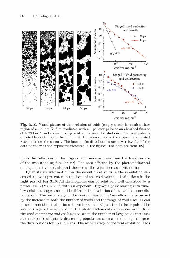
Fig. 3.10. Visual picture of the evolution of voids (empty space) in a sub-surfaceregion of a 100 nm Ni film irradiated with a 1 ps laser pulse at an absorbed fluenceof 1623 Jm−2 and corresponding void abundance distributions. The laser pulse isdirected from the top of the figure and the region shown in the snapshots is located∼20 nm below the surface. The lines in the distributions are power law fits of thedata points with the exponents indicated in the figures. The data are from [68]
upon the reflection of the original compressive wave from the back surfaceof the free-standing film [68, 82]. The area affected by the photomechanicaldamage quickly expands, and the size of the voids increases with time.
Quantitative information on the evolution of voids in the simulation dis-cussed above is presented in the form of the void volume distributions in theright part of Fig. 3.10. All distributions can be relatively well described by apower law N (V) ∼ V−τ, with an exponent –τ gradually increasing with time.Two distinct stages can be identified in the evolution of the void volume dis-tributions. The initial stage of the void nucleation and growth is characterizedby the increase in both the number of voids and the range of void sizes, as canbe seen from the distributions shown for 30 and 34 ps after the laser pulse. Thesecond stage of the evolution of the photomechanical damage corresponds tothe void coarsening and coalescence, when the number of large voids increasesat the expense of quickly decreasing population of small voids, e.g., comparethe distributions for 36 and 40 ps. The second stage of the void evolution leads

3 Atomic/Molecular-Level Simulations of Laser–Materials Interactions 67
to the eventual percolation of the empty volume and ejection of large liquidlayer (or droplets) from the irradiated side of the film.
The two stages in the evolution of void volume distribution, discussedabove for photomechanical spallation of a metal film [68], have also beenobserved in simulations of laser spallation of molecular targets [82]. Moreover,the time dependences of the power law exponent predicted in the simulationsperformed for these two drastically different materials, amorphous molecularsystems [82] and crystalline metal targets [68, 82], are in an excellent quan-titative agreement with each other. The power law dependences have alsobeen reported for the void volume distributions observed in MD simulationsof shock-induced, back-surface spallation of metal targets [165]. The criticalpower law exponent predicted for void distribution in the MD simulationsof shock-induced, back-surface spallation, τ ∼ 2.2, is close to the ones thatseparate the two regimes of void evolution observed in the simulations of laser-induced, front-surface spallation of the molecular and metal targets [68, 82].These observations suggest that the spallation mechanisms identified in [68,82]and briefly described in this section may reflect general characteristics of thedynamic fracture at high deformation rates.
3.3.4 Phase Explosion and Laser Ablation
At a sufficiently high laser fluence, the surface region of the irradiated targetcan be overheated above the limit of its thermodynamic stability, leadingto an explosive decomposition of the overheated material into a mixture ofvapor and liquid droplets. This process, commonly called “phase explosion”or “explosive boiling,” results in the ejection (ablation) of a multicomponentplume consisting of individual atoms/molecules, small clusters, and largerliquid droplets.
The mechanisms of laser ablation have been extensively investigated in MDsimulations addressing various aspects of the ablation process [70, 78, 79, 83–115]. One of the findings of the simulations is the existence of a well-definedthreshold fluence for the transition from surface evaporation (desorptionregime) to the collective material ejection (ablation regime) [70, 79, 100, 104,109]. The threshold behavior in laser ablation can be related to the sharptransition from a metastable superheated liquid to a two-phase mixture ofliquid and vapor (explosive boiling) at a temperature of approximately 90%of the critical temperature, as predicted based on the classical nucleation the-ory [166–169] and confirmed in simulations [170]. Experimental observationsof the existence of a threshold fluence for the onset of the droplet ejection,as well as a steep increase of the ablation rate at the threshold, have alsobeen interpreted as evidence of the transition from normal vaporization tothe phase explosion [169,171–173].
The active processes occurring in the vicinity of the irradiated surface dur-ing the first hundreds of picoseconds after the laser irradiation are illustratedin Fig. 3.11, where snapshots from a coarse-grained MD simulation of laser

68 L.V. Zhigilei et al.
Fig. 3.11. Snapshots from a coarse-grained MD simulation of laser ablation of apolymer solution with polymer concentration of 6wt.% [113]. The model is param-eterized to represent PMMA in toluene and the simulation is performed at anabsorbed laser fluence of 80 Jm−2, pulse duration of 50 ps, and optical penetra-tion depth of 50 nm. Matrix molecules and units of polymer chains are shown byblack and blue dots, respectively
ablation of a frozen polymer solution with polymer concentration of 6 wt.%are shown. The simulation is performed with a laser pulse duration of 50 ps,optical penetration depth of 50nm, and an absorbed laser fluence of 80 J m−2,about twice the ablation threshold for this model system [113]. In the firstsnapshot, shown for 100ps, 50ps after the end of the laser pulse, we see ahomogeneous expansion of a significant part of the surface region. The homo-geneous expansion is followed by the appearance of density fluctuations andgradual decomposition of the expanding plume into gas-phase molecules andliquid-phase regions. The decomposition of the expanding plume leads to theformation of a foamy transient structure of interconnected liquid regions, asshown in the snapshot at 200 ps. The foamy transient structure subsequentlydecomposes into separate liquid regions and vapor-phase molecules, forminga multicomponent ablation plume that expands away from the target.
While in the simulations performed for one-component molecular targetsthe liquid regions emerging from the explosive decomposition of the overheatedregion quickly develop into well-defined spherical liquid droplets [110,174], theentanglement of polymer chains in laser ablation of polymer solutions facili-tates the formation of intricate, elongated viscous structures that extend farabove the ablating surface, e.g., snapshot for 600ps in Fig. 3.11. The elongatedliquid structures that eventually separate from the target can be stabilized

3 Atomic/Molecular-Level Simulations of Laser–Materials Interactions 69
by evaporative cooling in the expanding plume and can reach the substratein matrix-assisted pulsed laser evaporation (MAPLE) film deposition tech-nique [175–177], contributing to the roughness of the deposited films [178–182](see Chap. 9 of this book for a detailed discussion of MAPLE). Indeed, the ejec-tion of the extended liquid structures observed in the simulations [113], can berelated to “nanofiber” or “necklace” polymer surface features observed in SEMimages of PMMA films deposited in MAPLE [124–126,182], as well as in filmsfabricated by ablation of a polymer target involving a partial thermal decom-position of the target material into volatile species [183]. Moreover, the effectof dynamic molecular redistribution in the ejected matrix-polymer droplets,leading to the generation of transient “molecular balloons” in which polymer-rich surface layers enclose the volatile matrix material, has been identified inthe simulations [114,126,184] as the mechanism responsible for the formationof characteristic wrinkled polymer structures observed experimentally in filmsdeposited by MAPLE [114,126,182].
Regardless of the specific characteristics of the phase explosion affected bythe properties of the target material and irradiation conditions, an importantgeneral conclusion that can be drawn from the results of MD simulationsperformed for different target materials, from metals to multicomponentmolecular systems, is that particles/droplets and small atomic/molecular clus-ters are unavoidable products of the processes responsible for the materialejection in the ablation regime, e.g., [70,87–89,109,110,113,125]. The energydensity deposited by the laser pulse is decreasing with depth under the irra-diated surface, leading to the strong dependence of the character of materialdecomposition from the depth of origin of the ejected material. Even when thelaser fluence is sufficiently high to induce a complete vaporization of the sur-face layer of the target, the decrease of the energy density with depth results inthe increase in the fraction of the liquid phase that emerges from the explo-sive phase decomposition [110, 185]. Since it is the amount of the releasedvapor phase that provides the driving force for the material decompositionand plume expansion, the decomposition process becomes less vigorous withdepth, resulting in lower ejection velocities of droplets/clusters produced athigher depth in the target.
The difference in the characteristics of the phase explosion occurring indifferent parts of the target results in the effect of spatial segregation of clus-ters/droplets of different sizes in the plume. In particular, a detailed analysisof the dynamics of the plume formation in simulations performed for molec-ular targets with both long (no stress confinement) [110] and short (stressconfinement) [185] laser pulses and fluences about twice the threshold for theablation onset, reveals that only small clusters and monomers are ejected atthe front of the expanding plume, medium-sized clusters are localized in themiddle of the expanding plume, whereas the larger liquid droplets formed laterduring the plume development tend to be slower and are closer to the originalsurface. The cluster segregation effect, predicted in the simulations, can berelated to the recent results of plume imaging experiments [186–190], where

70 L.V. Zhigilei et al.
splitting of the plume into a fast component with optical emission character-istic for neutral atoms and a slow component with blackbody-like emissionattributed to the presence of hot clusters [191], is observed. Similarly, andconsistently with the results of the simulations discussed in [110, 185], a lay-ered structure of the plume (vaporized layer followed by small particles andlarger droplets) observed in nanosecond laser ablation of water and soft tissue[192], is attributed to the succession of phase transitions occurring at differ-ent depths in the irradiated target [192,193]. More examples of experimentalobservations suggesting the spatial segregation of clusters/droplets of differentsizes in the plume can be found in Chap. 6 of this book.
Despite being ejected from deeper under the surface, where the energydensity deposited by the laser pulse is smaller, the larger clusters in the plumeare found to have substantially higher internal temperatures when comparedwith the smaller clusters [110, 185]. The lower temperature of the smallerclusters can be attributed to a more vigorous phase explosion (a larger fractionof the vapor-phase molecules is released due to a higher degree of overheating)and a fast expansion of the upper part of the plume that provides a moreefficient cooling when compared with a slower cooling of the larger clustersdominated by evaporation.
Depending on the irradiation conditions, as well as the thermodynamic,mechanical, and electronic properties of the target material, the thermal phaseexplosion may be intertwined with other processes, such as the generation ofthe thermoelastic stresses in the regime of stress confinement (see Sect. 3.3.3),photochemical reactions in organic systems, or optical breakdown plasma gen-eration in dielectrics. In particular, it has been observed in MD simulationsof molecular systems [78,79] and metals [109] that larger and more numerousclusters with higher ejection velocities are produced by the explosive phasedecomposition in the regime of stress confinement when compared with sim-ulations performed at the same laser fluences, but with longer pulses, in theregime of thermal confinement. Moreover, the transient tensile stresses gen-erated in the regime of stress confinement can bring the system deeper intothe metastable region and induce nucleation and growth of vapor bubbles atfluences at which no homogeneous boiling takes place without the assistanceof thermoelastic stresses [5, 193, 194], thus shifting the threshold fluence forthe ablation onset to lower values [78, 79, 109].
3.4 Concluding Remarks
MD simulation technique has successfully been adopted for simulation oflaser–materials interactions. Recent developments of the coarse-grained mod-els for molecular systems and a combined continuum-atomistic TTM–MDmodel for metals have provided computationally efficient means for incor-poration of a description of the laser energy coupling and equilibration into

3 Atomic/Molecular-Level Simulations of Laser–Materials Interactions 71
the classical MD method. The design of special heat-conductive, pressure-transmitting boundary conditions eliminates the need to model parts of thesystem where no structural transformations take place, further improving theefficiency of MD simulations of laser–materials interactions.
The examples of application of the MD simulation technique, brieflyreviewed in this chapter, demonstrate the ability of atomic/molecular-levelsimulations to provide insights into the complex nonequilibrium processesresponsible for material modification or removal in laser-processing applica-tions. MD simulations of laser melting, generation of crystal defects, spal-lation, and ablation have already made contributions to the interpretationof experimental results and the advancement of theoretical understanding oflaser-induced processes. With further innovative development of computa-tional methodology and the fast growth of the available computing resources,one can expect that MD modeling will continue to play an increasinglyimportant role in the investigation of laser interactions with materials.
One of the challenging directions of future work is the development ofmultiscale models for simulation of the processes occurring at the length-scale of the entire laser spot. For investigation of the long-term expansionof the ablation plume, in particular, a combination of MD with the DSMCmethod [195] has been demonstrated to be a promising approach capable offollowing the evolution of the parameters of the ablation plume on the scales,characteristic for experimental conditions, up to hundreds of microsecondsand millimeters [50–55]. In the combined MD–DSMC model [78,185,187,196–199], MD is used for simulation of the initial stage of the ablation process (firstnanoseconds) and provides the initial conditions for DSMC simulation of theprocesses occurring during the long-term expansion of the ejected plume. Firstapplications of the combined MD–DSMC model for simulation of laser inter-actions with molecular systems have demonstrated the ability of the modelto reveal interrelations between the processes occurring at different time- andlength-scales and responsible for the evolution of the characteristics of theablation plume [187,197–199]. In particular, the initial generation of clustersin the phase explosion, predicted in MD simulations, is found to provide clus-ter precursors for condensation during the long-term plume expansion, thuseliminating the three-body collision bottleneck in the cluster growth process(see Chap. 5). The presence of clusters makes a strong impact on the followingcollisional condensation and evaporation processes, affecting the cluster com-position of the plume, as well as the overall dynamics of the plume expansion[187,197–199].
In addition to using MD model for direct simulation of laser–materialsinteractions, the detailed information on laser-induced structural and phasetransformations, revealed in MD simulations, can help in the development ofcontinuum-level hydrodynamic models. As briefly discussed in the introduc-tion, the adaptation of the hydrodynamic computational models based on mul-tiphase equations-of-state [56–62] for simulations of laser–materials interac-tions involve a number of assumptions on the kinetics of phase transformations,

72 L.V. Zhigilei et al.
evolution of photomechanical damage under the action of laser-induced ten-sile stresses, characteristics of the ablation plume generated as a result of theexplosive decomposition of the overheated surface region in laser ablation,etc. The results of MD simulations on the kinetics and mechanisms of melt-ing, spallation, and ablation, e.g., [66,68,82,109,110,152,170,200], can be usedto provide the necessary information for the design of a reliable description ofthe fast nonequilibrium processes within a continuum model [60, 61, 96].
Further expansion of the domain of applicability of the MD-type of simula-tions into the area of laser interactions with complex multicomponent systems,such as nanocomposite materials or biological tissue, may involve the designof novel mesoscopic models, possibly based on the dynamic elements differ-ent from spherical particles, e.g., [201, 202]. Finally, an incorporation of theinformation on the transient changes in the interatomic bonding and thermo-physical properties of the target material in the electronically excited state(Stages 1 and 2 in Fig. 3.1), revealed in electronic structure calculations andtheoretical analysis, e.g., [23–36, 131–133], into large-scale atomistic simula-tions is needed for investigation of the implications of the initial ultrafastatomic dynamics for the final outcome of short-pulse laser irradiation.
Acknowledgements
Financial support of this work is provided by the National Science Foun-dation (USA) through grants CTS-0348503, DMII-0422632, CMMI-0800786,and DMR-0907247. The authors would like to thank Barbara J. Garrison ofPenn State University (USA), Aaron T. Sellinger and James M. Fitz-Geraldof the University of Virginia (USA), Antonio Miotello of the University ofTrento (Italy), Nadezhda Bulgakova of the Institute of Thermophysics SBRAS (Russia), Alfred Vogel of the Institute of Biomedical Optics in Lubeck(Germany), Roland Hergenroder of the Institute for Analytical Sciences inDortmund (Germany), and Tatiana Itina and Jorg Hermann of the CNRSLaboratory of Lasers, Plasmas, and Photonic Processing in Marseille (France),for insightful and stimulating discussions.
References
1. D. Bauerle, Laser Processing and Chemistry (Springer, Berlin, 2000)2. R.R. Gattass, E. Mazur, Nat. Photon. 2, 219–225 (2008)3. D.B. Chrisey, G.K. Hubler (eds), Pulsed Laser Deposition of Thin Films
(Wiley, New York, 1994)4. M.H. Niemz, Laser-Tissue Interactions: Fundamentals and Applications
(Springer, Berlin, 1996)5. A. Vogel, V. Venugopalan, Chem. Rev. 103, 577–644 (2003)6. V. Zafiropulos, in Laser Cleaning, ed. by B. Luk’yanchuk (World Scientific,
Singapore, 2002), p. 3437. A. Nevin, P. Pouli, S. Georgiou, C. Fotakis, Nat. Mater. 6, 320–322 (2007)

3 Atomic/Molecular-Level Simulations of Laser–Materials Interactions 73
8. E.I. Moses, R.E. Bonanno, C.A. Haynam, R.L. Kauffman, B.J. MacGowan,R.W. Patterson Jr, R.H. Sawicki, B.M. Van Wonterghem, Eur. Phys. J. D 44,215–218 (2007)
9. L. Huang, J.P. Callan, E.N. Glezer, E. Mazur, Phys. Rev. Lett. 80, 185–188(1998)
10. M.B. Agranat, S.I. Ashitkov, V.E. Fortov, A.V. Kirillin, A.V. Kostanovskii,S.I. Anisimov, P.S. Kondratenko, Appl. Phys. A 69, 637–640 (1999)
11. C. Guo, G. Rodriguez, A. Lobad, A.J. Taylor, Phys. Rev. Lett. 84, 4493–4496(2000)
12. O.P. Uteza, E.G. Gamaly, A.V. Rode, M. Samoc, B. Luther-Davies, Phys. Rev.B 70, 054108 (2004)
13. J. Wang, C. Guo, Phys. Rev. B 75, 184304 (2007)14. A. Rousse, G. Rischel, S. Fourneaux, I. Uschmann, S. Sebban, G. Grillon,
P.h. Balcou, E. Forster, J.P. Geindre, P. Audebert, J.C. Gauthier, D. Hulin,Nature 410, 65–68 (2001)
15. A.M. Lindenberg, J. Larsson, K. Sokolowski-Tinten, K.J. Gaffney, C. Blome,O. Synnergren, J. Sheppard, C. Caleman, A.G. MacPhee, D. Weinstein, D.P.Lowney, T.K. Allison, T. Matthews, R.W. Falcone, A.L. Cavalieri, D.M. Fritz,S.H. Lee, P.H. Bucksbaum, D.A. Reis, J. Rudati, P.H. Fuoss, C.C. Kao, D.P.Siddons, R. Pahl, J. Als-Nielsen, S. Duesterer, R. Ischebeck, H. Schlarb, H.Schulte-Schrepping, T.H. Tschentscher, J. Schneider, D. von der Linde, O.Hignette, F. Sette, H.N. Chapman, R.W. Lee, T.N. Hansen, S. Techert, J.S.Wark, M. Bergh, G. Huldt, D. van der Spoel, N. Timneanu, J. Hajdu, R.A.Akre, E. Bong, P. Krejcik, J. Arthur, S. Brennan, K. Luening, J.B. Hastings,Science 308, 392–395 (2005)
16. K. Sokolowski-Tinten, C. Blome, J. Blums, A. Cavalleri, C. Dietrich, A. Tara-sevich, I. Uschmann, E. Forster, M. Kammler, M. Horn-von-Hoegen, D. vonder Linde, Nature 422, 287–289 (2003)
17. W.E. King, G.H. Campbell, A. Frank, B. Reed, J.F. Schmerge, B.J. Siwick,B.C. Stuart, P.M. Weber, J. Appl. Phys. 97, 111101 (2005)
18. S. Williamson, G. Mourou, J.C.M. Li, Phys. Rev. Lett. 52, 2364–2367 (1984)19. B.J. Siwick, J.R. Dwyer, R.E. Jordan, R.J.D. Miller, Science 302, 1382–1385
(2003)20. J.R. Dwyer, R.E. Jordan, C.T. Hebeisen, M. Harb, R. Ernstorfer, T. Dartiga-
longue, R.J.D. Miller, J. Mod. Optics 54, 905–922 (2007)21. M. Harbst, T.N. Hansen, C. Caleman, W.K. Fullagar, P. Jonsson, P. Sond-
hauss, O. Synnergren, J. Larsson, Appl. Phys. A 81, 893–900 (2005)22. A.M. Lindenberg, S. Engemann, K.J. Gaffney, K. Sokolowski-Tinten,
J. Larsson, P.B. Hillyard, D.A. Reis, D.M. Fritz, J. Arthur, R.A. Akre, M.J.George, A. Deb, P.H. Bucksbaum, J. Hajdu, D.A. Meyer, M. Nicoul, C. Blome,T.H. Tschentscher, A.L. Cavalieri, R.W. Falcone, S.H. Lee, R. Pahl, J. Rudati,P.H. Fuoss, A.J. Nelson, P. Krejcik, D.P. Siddons, P. Lorazo, J.B. Hastings,Phys. Rev. Lett. 100, 135502 (2008)
23. S. Mazevet, J. Clerouin, V. Recoules, P.M. Anglade, G. Zerah, Phys. Rev. Lett.95, 085002 (2005)
24. V. Recoules, J. Clerouin, G. Zerah, P.M. Anglade, S. Mazevet, Phys. Rev. Lett.96, 055503 (2006)
25. F. Bottin, G. Zerah, Phys. Rev. B 75, 174114 (2007)26. D. Dundas, J. Phys. B: At. Mol. Opt. Phys. 37, 2883–2901 (2004)

74 L.V. Zhigilei et al.
27. H.O. Jeschke, M.E. Garcia, Chap. 7 in Nonlinear Optics, Quantum Optics, andUltrafast Phenomena with X-Rays, ed. by B.W. Adams (Springer, New York,2003), p. 175
28. H.O. Jeschke, M.E. Garcia, M. Lenzner, J. Bonse, J. Kruger, W. Kautek, Appl.Surf. Sci. 197/198, 839–844 (2002)
29. P.L. Silvestrelli, A. Alavi, M. Parrinello, D. Frenkel, Phys. Rev. Lett. 77, 3149–3152 (1996)
30. P.L. Silvestrelli, Phys. Rev. B 60, 16382–16388 (1999)31. P.L. Silvestrelli, A. Alavi, M. Parrinello, D. Frenkel, Phys. Rev. B 56, 3806–
3812 (1997)32. L.X. Benedict, C.D. Spataru, S.G. Louie, Phys. Rev. B 66, 085116 (2002)33. P.B. Hillyard, D.A. Reis, K.J. Gaffney, Phys. Rev. B 77, 195213 (2008)34. R.E. Allen, T. Dumitrica, B. Torralva, Chap. 7 in Ultrafast Physical Processes
in Semiconductors, ed. by K.T. Tsen (Academic, New York, 2000), p. 31535. B. Torralva, T.A. Niehaus, M. Elstner, S. Suhai, T.h. Frauenheim, R.E. Allen,
Phys. Rev. B 64, 153105 (2001)36. T. Dumitrica, A. Burzo, Y. Dou, R.E. Allen, Phys. Stat. Solidi B 241, 2331–
2342 (2004)37. V.A. Gnatyuk, T. Aoki, O.S. Gorodnychenko, Y. Hatanaka, Appl. Phys. Lett.
83, 3704–3706 (2003)38. K.N. Vonatsos, D.I. Pantelis, Appl. Phys. A 80, 885–889 (2005)39. V.N. Tokarev, A.F.H. Kaplan, J. Appl. Phys. 86, 2836–2846 (1999)40. R.Cerny R. Sarsik, I. Lukes, V. Chab, Phys. Rev. B 44, 4097–4102 (1991)41. X. Xu, G. Chen, K.H. Song, Int. J. Heat Mass Transf. 42, 1371–1382 (1999)42. J.C. Kapat, Z. Wei, A. Kumar, Appl. Surf. Sci. 127–129, 212–217 (1998)43. G.X. Wang, E.F. Matthys, Trans. ASME 118, 944–951 (1996)44. I.H. Chowdhury, X. Xu, Num. Heat Transf. A 44, 219–232 (2003)45. R.K. Singh, J. Narayan, Phys. Rev. B 41, 8843–8858 (1990)46. A. Peterlongo, A. Miotello, R. Kelly, Phys. Rev. E 50, 4716–4727 (1994)47. J.R. Ho, C.P. Grigoropoulos, J.A.C. Humphrey, J. Appl. Phys. 78, 4696–4709
(1995)48. A. Bogaerts, Z. Chen, R. Gijbels, A. Vertes, Spectrochim. Acta. B 58, 1867–
1893 (2003)49. Z. Chen, A. Vertes, Phys. Rev. E 77, 036316 (2008)50. I. NoorBatcha, R.R. Lucchese, Y. Zeiri, J. Chem. Phys. 86, 5816–5824 (1987)51. H.M. Urbassek, D. Sibold, Phys. Rev. Lett. 70, 1886–1889 (1993)52. O. Ellegaard, J. Schou, H.M. Urbassek, Appl. Phys. A 69, S577-S582 (1999)53. T.E. Itina, W. Marine, M. Autric, J. Appl. Phys. 82, 3536–3542 (1997)54. T.E. Itina, W. Marine, M. Autric, J. Appl. Phys. 85, 7905–7908 (1999)55. A.A. Morozov, Phys. Fluids 19, 087101 (2007)56. K. Eidmann, J. Meyer-ter-Vehn, T. Schlegel, S. Huller, Phys. Rev. E 62, 1202–
1214 (2000)57. Y. Kondoh, T. Yabe, J. Maehara, T. Nakamura, Y. Ogata, Phys. Rev. E 68,
066408 (2003)58. F. Vidal, T.W. Johnston, J.C. Kieffer, F. Martin, Phys. Rev. B 70, 184125
(2004)59. J.P. Colombier, P. Combis, F. Bonneau, R. Le Harzic, E. Audouard, Phys.
Rev. B 71, 165406 (2005)60. M.E. Povarnitsyn, T.E. Itina, M. Sentis, K.V. Khishchenko, P.R. Levashov,
Phys. Rev. B 75, 235414 (2007)

3 Atomic/Molecular-Level Simulations of Laser–Materials Interactions 75
61. A.N. Volkov, L.V. Zhigilei, J. Phys. Conf. Ser. 59, 640–645 (2007)62. A.N. Volkov, C. Sevilla, L.V. Zhigilei, Appl. Surf. Sci. 253, 6394–6399 (2007)63. C.F. Richardson, P. Clancy, Mol. Simul. 7, 335–355 (1991)64. H. Hakkinen, U. Landman, Phys. Rev. Lett. 71, 1023–1026 (1993)65. D.S. Ivanov, L.V. Zhigilei, Phys. Rev. B 68, 064114 (2003)66. D.S. Ivanov, L.V. Zhigilei, Phys. Rev. Lett. 91, 105701 (2003)67. D.S. Ivanov, L.V. Zhigilei, Appl. Phys. A 79, 977–981 (2004)68. L.V. Zhigilei, D.S. Ivanov, E. Leveugle, B. Sadigh, E.M. Bringa, in High-Power
Laser Ablation V, ed. by C.R. Phipps, Proc. SPIE 5448, 505–519 (2004)69. L.V. Zhigilei, D.S. Ivanov, Appl. Surf. Sci. 248, 433–439 (2005)70. L.V. Zhigilei, Z. Lin, D.S. Ivanov, in Proceedings of the 2006 ASME Interna-
tional Mechanical Engineering Congress and Exposition (IMECE2006), ASMEpaper IMECE2006–16305 (2006)
71. Z. Lin, L.V. Zhigilei, Phys. Rev. B 73, 184113 (2006)72. Z. Lin, L.V. Zhigilei, J. Phys. Conf. Ser. 59, 11–15 (2007)73. W.H. Duff, L.V. Zhigilei, J. Phys. Conf. Ser. 59, 413–417 (2007)74. Z. Lin, R.A. Johnson, L.V. Zhigilei, Phys. Rev. B 77, 214108 (2008)75. S.I. Anisimov, V.V. Zhakhovskii, N.A. Inogamov, K. Nishihara, A.M. Oparin,
Y.V. Petrov, Pis’ma Zh. Eksp. Teor. Fiz. 77, 731–736 (2003) [JETP Lett. 77,606–610 (2003)]
76. A.K. Upadhyay, H.M. Urbassek, J. Phys. D 38, 2933–2941 (2005)77. H.Y. Lai, P.H. Huang, Appl. Surf. Sci. 254, 3067–3073 (2008)78. L.V. Zhigilei, E. Leveugle, B.J. Garrison, Y.G. Yingling, M.I. Zeifman, Chem.
Rev. 103, 321–348 (2003)79. L.V. Zhigilei, B.J. Garrison, J. Appl. Phys. 88, 1281–1298 (2000)80. A.G. Zhidkov, L.V. Zhigilei, A. Sasaki, T. Tajima, Appl. Phys. A 73, 741–747
(2001)81. E. Leveugle, L.V. Zhigilei, Appl. Phys. A 79, 753–756 (2004)82. E. Leveugle, D.S. Ivanov, L.V. Zhigilei, Appl. Phys. A 79, 1643–1655 (2004)83. E. Ohmura, I. Fukumoto, Int. J. Japan Soc. Prec. Eng. 30, 128–133 (1996)84. E. Ohmura, I. Fukumoto, I. Miyamoto, Int. J. Jpn. Soc. Precis. Eng. 32, 248–
253 (1998)85. R.F.W. Herrmann, J. Gerlach, E.E.B. Campbell, Appl. Phys. A 66, 35–42
(1998)86. X. Wu, M. Sadeghi, A. Vertes, J. Phys. Chem. B 102, 4770–4778 (1998)87. S. Kristyan, A. Bensura, A. Vertes, Theor. Chem. Acc. 107, 319–325 (2002)88. X. Xu, C. Cheng, I.H. Chowdhury, ASME Trans. J. Heat Transf. 126, 727–734
(2004)89. C. Cheng, X. Xu, Phys. Rev. B 72, 165415 (2005)90. X.W. Wang, X.F. Xu, J. Heat Transf. 124, 265–274 (2002)91. X.W. Wang, J. Phys. D 38, 1805–1823 (2005)92. P. Lorazo, L.J. Lewis, M. Meunier, Phys. Rev. B 73, 134108 (2006)93. P. Lorazo, L.J. Lewis, M. Meunier, Phys. Rev. Lett. 91, 225502 (2003)94. N.N. Nedialkov, P.A. Atanasov, Appl. Surf. Sci. 252, 4411–4415 (2006)95. N.N. Nedialkov, P.A. Atanasov, S.E. Imamova, A. Ruf, P. Berger, F. Dausinger,
Appl. Phys. A 79, 1121–1125 (2004)96. S.I. Anisimov, V.V. Zhakhovskii, N.A. Inogamov, K. Nishihara, Y.V. Petrov,
V.A. Khokhlov, J. Exp. Theor. Phys. 103, 183–197 (2006)

76 L.V. Zhigilei et al.
97. M.B. Agranat, S.I. Anisimov, S.I. Ashitkov, V.V. Zhakhovskii, N.A. Inogamov,K. Nishihara, Y.V. Petrov, V.E. Fortov, V.A. Khokhlov, Appl. Surf. Sci. 253,6276–6282 (2007)
98. L.V. Zhigilei, P.B.S. Kodali, B.J. Garrison, J. Phys. Chem. B 101, 2028–2037(1997)
99. L.V. Zhigilei, B.J. Garrison, Appl. Phys. Lett. 71, 551–553 (1997)100. L.V. Zhigilei, P.B.S. Kodali, B.J. Garrison, Chem. Phys. Lett. 276, 269–273
(1997)101. L.V. Zhigilei, P.B.S. Kodali, B.J. Garrison, J. Phys. Chem. B 102, 2845–2853
(1998)102. L.V. Zhigilei, B.J. Garrison, Rapid Commun. Mass Spectrom. 12, 1273–1277
(1998)103. L.V. Zhigilei, B.J. Garrison, Appl. Phys. Lett. 74, 1341–1343 (1999)104. L.V. Zhigilei, B.J. Garrison, Appl. Phys. A 69, S75–S80 (1999)105. Y.G. Yingling, L.V. Zhigilei, B.J. Garrison, A. Koubenakis, J. Labrakis,
S. Georgiou, Appl. Phys. Lett. 78, 1631–1633 (2001)106. Y.G. Yingling, L.V. Zhigilei, B.J. Garrison, J. Photochem. Photobiol. A 145,
173–181 (2001)107. T.E. Itina, L.V. Zhigilei, B.J. Garrison, J. Phys. Chem. B 106, 303–310 (2002)108. C. Schafer, H.M. Urbassek, L.V. Zhigilei, Phys. Rev. B 66, 115404 (2002)109. L.V. Zhigilei, Z. Lin, D.S. Ivanov, J. Phys. Chem. C 113, 11892–11906 (2009)110. L.V. Zhigilei, Appl. Phys. A 76, 339–350 (2003)111. Y.G. Yingling, B.J. Garrison, J. Phys. Chem. B 109, 16482–16489 (2005)112. R. Knochenmuss, L.V. Zhigilei, J. Phys. Chem. B 109, 22947–22957 (2005)113. E. Leveugle, L.V. Zhigilei, J. Appl. Phys. 102, 074914 (2007)114. E. Leveugle, A. Sellinger, J.M. Fitz-Gerald, L.V. Zhigilei, Phys. Rev. Lett. 98,
216101 (2007)115. M. Prasad, P. Conforti, B.J. Garrison, J. Appl. Phys. 101, 103113 (2007)116. M.P. Allen, D.J. Tildesley, Computer Simulation of Liquids (Clarendon,
Oxford, 1990, 1987)117. D. Frenkel, B. Smit, Understanding Molecular Simulation: From Algorithms to
Applications (Academic, San Diego, 1996)118. K. Kadau, T.C. Germann, P.S. Lomdahl, Int. J. Mod. Phys. C 17, 1755–1761
(2006)119. http://folding.stanford.edu/120. J.C. Deak, L.K. Iwaki, S.T. Rhea, D.D. Dlott, J. Raman Spectrosc. 31, 263–274
(2000)121. S. Woutersen, H.J. Bakker, Nature 402, 507–509 (1999)122. H. Kim, D.D. Dlott, Y. Won, J. Chem. Phys. 102, 5480–5485 (1995)123. R.E. Wyatt, C. Iung, C. Leforestier, Acc. Chem. Res. 28, 423–429 (1995)124. E. Leveugle, L.V. Zhigilei, A. Sellinger, J.M. Fitz-Gerald, J. Phys. Conf. Ser.
59, 126–131 (2007)125. E. Leveugle, L.V. Zhigilei, A. Sellinger, J.M. Fitz-Gerald, Appl. Surf. Sci. 253,
6456–6460 (2007)126. A. Sellinger, E. Leveugle, J.M. Fitz-Gerald, L.V. Zhigilei, Appl. Phys. A 92,
821 (2008)127. E.A. Colbourn (ed.) Computer Simulation of Polymers (Longman Scientific
and Technical, Harlow, 1994)128. F. Gao, D.J. Bacon, P.E.J. Flewitt, T.A. Lewis, Modelling Simul. Mater. Sci.
Eng. 6, 543–556 (1998)

3 Atomic/Molecular-Level Simulations of Laser–Materials Interactions 77
129. D.M. Duffy, A.M. Rutherford, J. Phys: Condens. Matter 19, 016207 (2007)130. S.I. Anisimov, B.L. Kapeliovich, T.L. Perel’man, Sov. Phys. JETP 39, 375–377
(1974)131. Z. Lin, L.V. Zhigilei, Appl. Surf. Sci. 253, 6295–6300 (2007)132. Z. Lin, L.V. Zhigilei, in High-Power Laser Ablation VI, ed. by C.R. Phipps,
Proc. SPIE 6261, 62610U (2006)133. Z. Lin, L.V. Zhigilei, V. Celli, Phys. Rev. B 77, 075133 (2008)134. http://www.faculty.virginia.edu/CompMat/electron-phonon-coupling/135. N. Rotenberg, A.D. Bristow, M. Pfeiffer, M. Betz, H.M. van Driel, Phys. Rev.
B 75, 155426 (2007)136. M.S. Daw, S.M. Foiles, M.I. Baskes, Mater. Sci. Rep. 9, 251–310 (1993)137. S.M. Foiles, MRS Bull. 21, 24–28 (1996)138. X.W. Zhou, H.N.G. Wadley, R.A. Johnson, D.J. Larson, N. Tabat, A. Cerezo,
A.K. Petford-Long, G.D.W. Smith, P.H. Clifton, R.L. Martens, T.F. Kelly,Acta Mater. 49, 4005–4015 (2001)
139. D.S. Ivanov, B. Rethfeld, G.M. O’Connor, T.h.J. Glynn, A.N. Volkov,L.V. Zhigilei, Appl. Phys. A 92, 791–796 (2008)
140. L.V. Zhigilei, B.J. Garrison, Mat. Res. Soc. Symp. Proc. 538, 491–496 (1999)141. C. Schafer, H.M. Urbassek, L.V. Zhigilei, B.J. Garrison, Comp. Mater. Sci. 24,
421–429 (2002)142. L.V. Zhigilei, B.J. Garrison, in Laser-Tissue Interaction IX, ed. by
S.L. Jacques, Proc. SPIE 3254, 135–143 (1998)143. V. Vitek, Philos. Mag. 21, 1275–1278 (1970)144. J.P. Hirth, J. Lothe, Theory of Dislocations, 2nd edn. (Wiley, New York, 1982)145. D. Ashkenasi, M. Lorenz, R. Stoian, A. Rosenfeld, Appl. Surf. Sci. 150, 101–106
(1999)146. P.T. Mannion, J. Magee, E. Coyne, G.M. O’Connor, T.J. Glynn, Appl. Surf.
Sci. 233, 275–287 (2004)147. S.E. Kirkwood, A.C. van Popta, Y.Y. Tsui, R. Fedosejevs, Appl. Phys. A 81,
729–735 (2005)148. J. Kruger, D. Dufft, R. Koter, A. Hertwig, Appl. Surf. Sci. 253, 7815–7819
(2007)149. G. Raciukaitis, M. Brikas, P. Gecys, M. Gedvilas, Proc. SPIE 7005, 70052L
(2008)150. J.G. Dash, Rev. Mod. Phys. 71, 1737–1743 (1999)151. P.R. Couchman, W.A. Jesser, Nature 269, 481–483 (1977)152. D.S. Ivanov, L.V. Zhigilei, Phys. Rev. Lett. 98, 195701 (2007)153. B. Rethfeld, K. Sokolowski-Tinten, D. von der Linde, S.I. Anisimov, Phys. Rev.
B 65, 092103 (2002)154. J.R. Dwyer, C.T. Hebeisen, R. Ernstorfer, M. Harb, V. Deyirmenjian,
R.E. Jordan, R.J.D. Miller, Phil. Trans. R. Soc. A 364, 741–778 (2006)155. S.N. Luo, T.J. Ahrens, T. Cagın, A. Strachan, W.A. Goddard, D.C. Swift,
Phys. Rev. B 68, 134206 (2003)156. V. Sorkin, E. Polturak, J. Adler, Phys. Rev. B 68, 174102 (2003)157. G. Paltauf, P.E. Dyer, Chem. Rev. 103, 487–518 (2003)158. I. Itzkan, D. Albagli, M.L. Dark, L.T. Perelman, C. von Rosenberg, M.S. Feld,
Proc. Natl. Acad. Sci. U S A 92, 1960–1964 (1995)159. A.A. Oraevsky, S.L. Jacques, F.K. Tittel, J. Appl. Phys. 78, 1281–1290 (1995)160. R. Cramer, R.F. Haglund Jr., F. Hillenkamp, Int. J. Mass Spectrom. Ion Proc.
169/170, 51–67 (1997)

78 L.V. Zhigilei et al.
161. H. Tamura, T. Kohama, K. Kondo, M. Yoshida, J. Appl. Phys. 89, 3520–3522(2001)
162. V.E. Fortov, V.V. Kostin, S. Eliezer, J. Appl. Phys. 70, 4524–4531 (1991)163. G.I. Kanel’, V.E. Fortov, S.V. Razorenov, Physics-Uspekhi 50, 771–791 (2007)164. Animated sequences of snapshots from a molecular dynamics simulation of laser
spallation of a molecular target can be found at http://www.faculty.virginia.edu/CompMat/spallation/animations/
165. A. Strachan, T. Cagin, W.A. Goddard III, Phys. Rev. B 63, 060103 (2001)166. M.M. Martynyuk, Sov. Phys. Tech. Phys. 21, 430–433 (1976)167. A. Miotello, R. Kelly, Appl. Phys. A 69, S67–S73 (1999)168. R. Kelly, A. Miotello, J. Appl. Phys. 87, 3177–3179 (2000)169. N.M. Bulgakova, A.V. Bulgakov, Appl. Phys. A 73, 199–208 (2001)170. B.J. Garrison, T.E. Itina, L.V. Zhigilei, Phys. Rev. E 68, 041501 (2003)171. K.H. Song, X. Xu, Appl. Surf. Sci. 127–129, 111–116 (1998)172. J.H. Yoo, S.H. Jeong, X.L. Mao, R. Greif, R.E. Russo, Appl. Phys. Lett. 76,
783–785 (2000)173. C. Porneala, D.A. Willis, Appl. Phys. Lett. 89, 211121 (2006)174. Animated sequences of snapshots from a molecular dynamics simulation of laser
ablation of a molecular target can be found at http://www.faculty.virginia.edu/CompMat/ablation/animations/
175. A. Pique, R.A. McGill, D.B. Chrisey, J. Callahan, T.E. Mlsna, Mater. Res.Soc. Symp. Proc. 526, 375–383 (1998)
176. A. Pique, R.A. McGill, D.B. Chrisey, D. Leonhardt, T.E. Mslna, B.J. Spargo,J.H. Callahan, R.W. Vachet, R. Chung, M.A. Bucaro, Thin Solid Films355/356, 536–541 (1999)
177. D.B. Chrisey, A. Pique, R.A. McGill, J.S. Horwitz, B.R. Ringeisen, D.M. Bubb,P.K. Wu, Chem. Rev. 103, 553–576 (2003)
178. R. Frycek, M. Jelınek, T. Kocourek, P. Fitl, M. Vrrata, V. Myslık, M. Vrbova,Thin Solid Films 495, 308–311 (2006)
179. D.M. Bubb, P.K. Wu, J.S. Horwitz, J.H. Callahan, M. Galicia, A. Vertes,R.A. McGill, E.J. Houser, B.R. Ringeisen, D.B. Chrisey, J. Appl. Phys. 91,2055–2058 (2002)
180. K. Rodrigo, P. Czuba, B. Toftmann, J. Schou, R. Pedrys, Appl. Surf. Sci. 252,4824–4828 (2006)
181. A. Gutierrez-Llorente, R. Perez-Casero, B. Pajot, J. Roussel, R.M. Defourneau,D. Defourneau, J.L. Fave, E. Millon, J. Perriere, Appl. Phys. A 77, 785–788(2003)
182. A.T. Sellinger, E.M. Leveugle, K. Gogick, L.V. Zhigilei, J.M. Fitz-Gerald,J. Vac. Sci. Technol. A 24, 1618–1622 (2006)
183. J. Blazevska-Gilev et al., Polym. Degrad. Stab. 91, 213–220 (2006)184. Animated sequences of snapshots from a molecular dynamics simulation of
the generation of “molecular balloons” in laser-induced explosive boiling ofpolymer solutions can be found at http://www.faculty.virginia.edu/CompMat/molecular-balloons/
185. L.V. Zhigilei, in Advances in Materials Theory and Modeling-Bridging OverMultiple-Length and Time Scales, ed. by V.V. Bulatov, F. Cleri, L. Colombo,L.J. Lewis, N. Mousseau, Mater. Res. Soc. Symp. Proc. 677 AA2.1.1 (2001)
186. S. Noel, J. Hermann, T. Itina, Appl. Surf. Sci. 253, 6310–6315 (2007)187. T.E. Itina, K. Gouriet, L.V. Zhigilei, S. Noel, J. Hermann, M. Sentis, Appl.
Surf. Sci. 253, 7656–7661 (2007)

3 Atomic/Molecular-Level Simulations of Laser–Materials Interactions 79
188. S. Amoruso, R. Bruzzese, C. Pagano, X. Wang, Appl. Phys. A 89, 1017–1024(2007)
189. O. Albert, S. Roger, Y. Glinec, J.C. Loulergue, J. Etchepare, C. Boulmer-Leborgne, J. Perriere, E. Millon, Appl. Phys. A 76, 319–323 (2003)
190. N. Jegenyes, J. Etchepare, B. Reynier, D. Scuderi, A. Dos-Santos, Z. Toth,Appl. Phys. A 91, 385–392 (2008)
191. D. Scuderi, R. Benzerga, O. Albert, B. Reynier, J. Etchepare, Appl. Surf. Sci.252, 4360–4363 (2006)
192. I. Apitz, A. Vogel, Appl. Phys. A 81, 329–338 (2005)193. A. Vogel, I. Apitz, V. Venugopalan, in Oscillations, Waves and Interactions, ed.
by T. Kurz, U. Parlitz, U. Kaatze (Universitatsverlag Gottingen, Gottingen,2007), p. 217
194. D. Kim, M. Ye, C.P. Grigoropoulos, Appl. Phys. A 67, 169–181 (1998)195. G.A. Bird, Molecular Gas Dynamics and the Direct Simulation of Gas F lows
(Clarendon, Oxford, 1994)196. L.V. Zhigilei, A.M. Dongare, Comput. Model. Eng. Sci 3, 539–555 (2002)197. M.I. Zeifman, B.J. Garrison, L.V. Zhigilei, J. Appl. Phys. 92, 2181–2193 (2002)198. M.I. Zeifman, B.J. Garrison, L.V. Zhigilei, Appl. Surf. Sci. 197/198, 27–34
(2002)199. T.E. Itina, L.V. Zhigilei, J. Phys. Conf. Ser 59, 44–49 (2007)200. T.E. Itina, Chem. Phys. Lett. 452, 129–132 (2008)201. L.V. Zhigilei, C. Wei, D. Srivastava, Phys. Rev. B 71, 165417 (2005)202. A.N. Volkov, K.R. Simov, L.V. Zhigilei, in Proceedings of ASME International
Mechanical Engineering Congress and Exposition, ASME paper IMECE2008–68021 (2008)