2.72 Elements of Mechanical Design - Free Online Course ... · PDF file2.72 Elements of...
31
MIT OpenCourseWare http://ocw.mit.edu 2.72 Elements of Mechanical Design Spring 2009 For information about citing these materials or our Terms of Use, visit: http://ocw.mit.edu/terms .
-
Upload
duongxuyen -
Category
Documents
-
view
219 -
download
0
Transcript of 2.72 Elements of Mechanical Design - Free Online Course ... · PDF file2.72 Elements of...
MIT OpenCourseWare http://ocw.mit.edu 2.72 Elements of Mechanical DesignSpring 2009
For information about citing these materials or our Terms of Use, visit: http://ocw.mit.edu/terms.
2.72Elements of
Mechanical Design
Lecture 10: Bolted joints
2© Martin Culpepper, All rights reserved
Bolted joint +’s and –’sGood:
Low cost?Able to be disassembledStrongCompatible with almost any material
Bad:Takes up a lot of spaceMicro-slip/hysteresis/damping problemsDifficult to model and controlCan require long fabrication and assembly time
3© Martin Culpepper, All rights reserved
Bolted joints: Their purposeBolted joints = connectors, impact many parts:
Stiffness Vibration Damping Stability Load capacity
Bolted joints are semi-permanent!Max benefit obtained when it is highly preloaded, i.e. near the yield pointThreads can plastically deform/work hardenSome elements of bolted joints are not reusable
Bolted joints are used to create assemblies that resist:(i) Tensile loads (ii) Moments (iii) Shear loads
Bolts are NOT meant to resist (i) – (iii)

Components
5© Martin Culpepper, All rights reserved
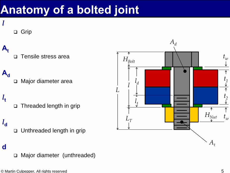
Anatomy of a bolted jointl
Grip
AtTensile stress area
AdMajor diameter area
ltThreaded length in grip
ldUnthreaded length in grip
dMajor diameter (unthreaded)
l
tw
tw
HBolt
LT
L
t1
t2
HNut
lt
ld
At
Ad
6© Martin Culpepper, All rights reserved
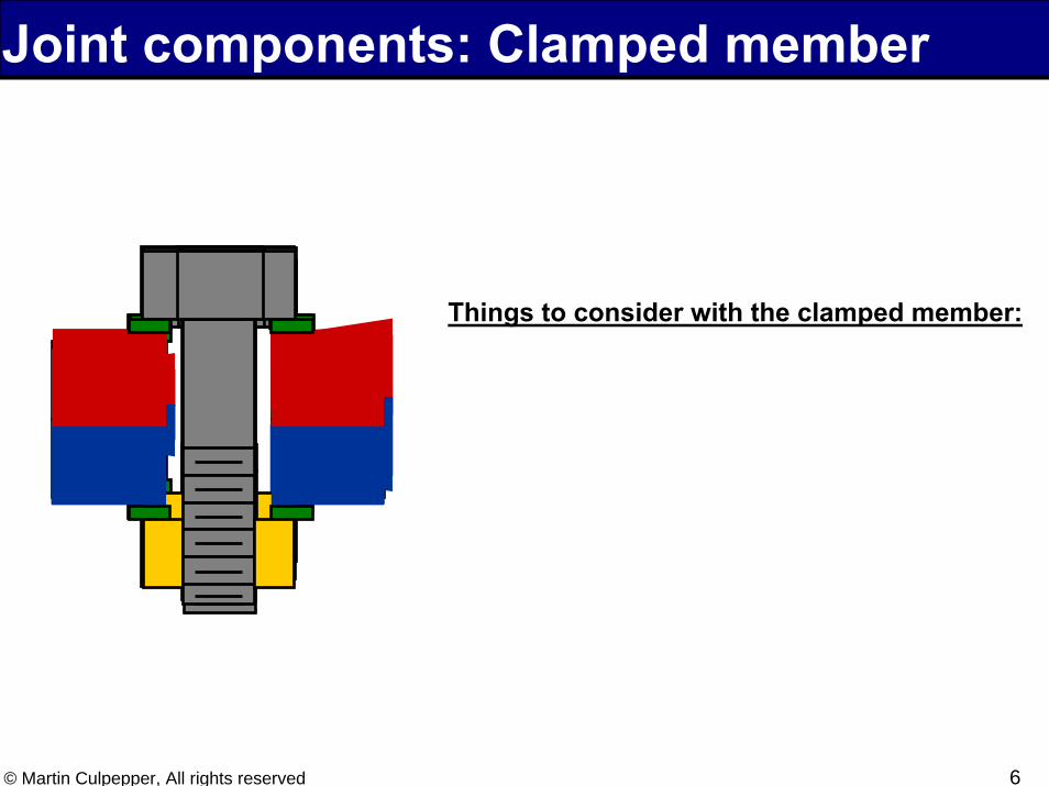
Things to consider with the clamped member:
1. Stone or lap the surface (increase stiffness)
2. Remove burs (increase joint stiffness)
3. Be sure flange surfaces are flat so bolt does not bend
Joint components: Clamped member
7© Martin Culpepper, All rights reserved
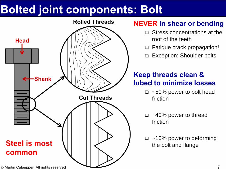
Rolled Threads
Cut Threads
Head
Shank
Steel is most common
Bolted joint components: BoltNEVER in shear or bending
Stress concentrations at the root of the teethFatigue crack propagation!Exception: Shoulder bolts
Keep threads clean & lubed to minimize losses
~50% power to bolt head friction
~40% power to thread friction
~10% power to deforming the bolt and flange
8© Martin Culpepper, All rights reserved
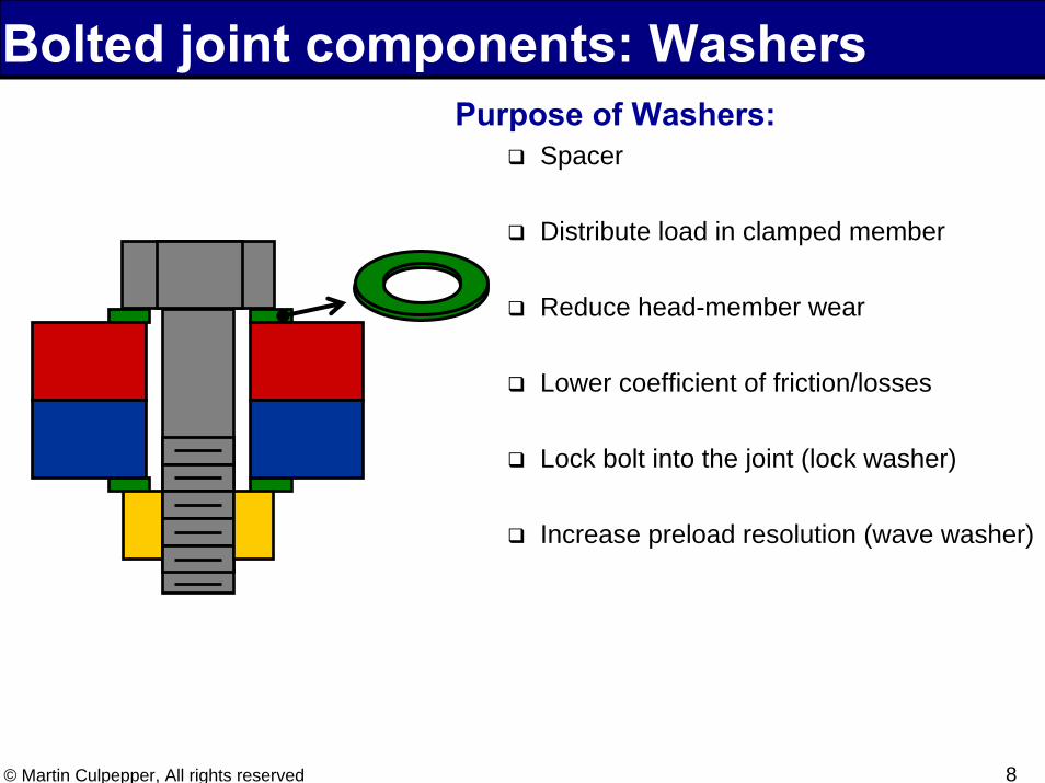
Bolted joint components: WashersPurpose of Washers:
Spacer
Distribute load in clamped member
Reduce head-member wear
Lower coefficient of friction/losses
Lock bolt into the joint (lock washer)
Increase preload resolution (wave washer)
9© Martin Culpepper, All rights reserved
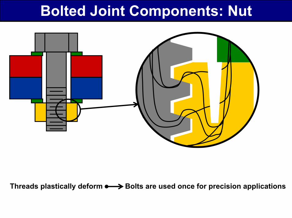
Bolted Joint Components: Nut
Threads do not distribute the load evenly:
1. First thread has the shortest load path (stiffest)
2. The pitch of the bolt threads and nut threads change as they are loaded
What can be done to distribute the load better
1. Use a softer nut material
2. Use a bolt and nut that have different pitch values to begin with
3. Use a special nut that lengthens the load path of the first thread
Threads plastically deform Bolts are used once for precision applications

Stiffness
11© Martin Culpepper, All rights reserved
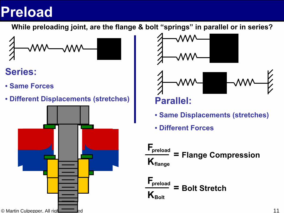
While preloading joint, are the flange & bolt “springs” in parallel or in series?
Series: • Same Forces
• Different Displacements (stretches) Parallel: • Same Displacements (stretches)
• Different Forces
Fpreload
Kflange= Flange Compression
Fpreload
KBolt= Bolt Stretch
Preload
12© Martin Culpepper, All rights reserved
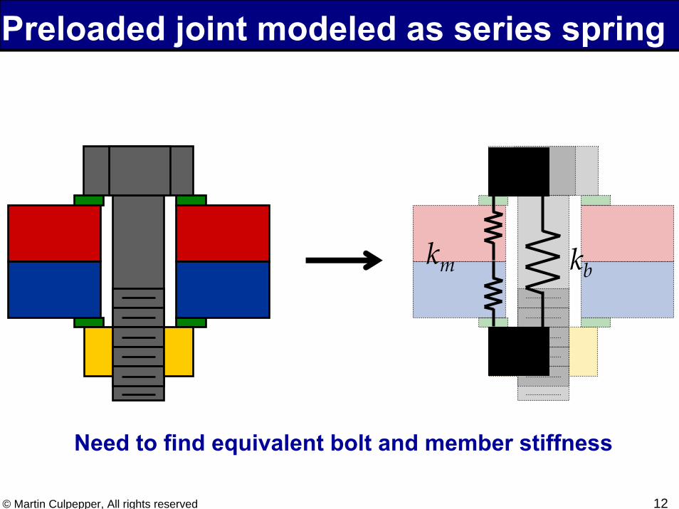
Preloaded joint modeled as series spring
km kb
Need to find equivalent bolt and member stiffness
13© Martin Culpepper, All rights reserved
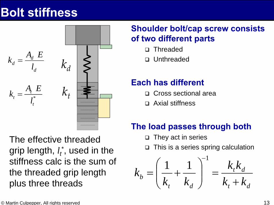
Bolt stiffnessShoulder bolt/cap screw consists of two different parts
ThreadedUnthreaded
Each has differentCross sectional areaAxial stiffness
The load passes through bothThey act in seriesThis is a series spring calculation
dt
dt
dtb kk
kkkk
k+
=⎟⎟⎠
⎞⎜⎜⎝
⎛+=
−111
d
dd l
EAk = kd
*t
tt
A Ekl
= kt
The effective threaded grip length, lt*, used in the stiffness calc is the sum of the threaded grip length plus three threads
14© Martin Culpepper, All rights reserved
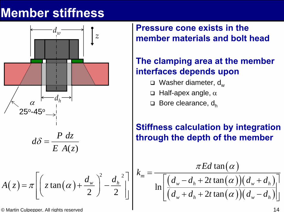
Member stiffnessPressure cone exists in the member materials and bolt head
The clamping area at the member interfaces depends upon
Washer diameter, dw
Half-apex angle, αBore clearance, dh
Stiffness calculation by integration through the depth of the member
)(zAEdzPd =δ
( ) ( )2 2
tan2 2w hd dA z zπ α
⎡ ⎤⎛ ⎞= + −⎢ ⎥⎜ ⎟⎝ ⎠⎢ ⎥⎣ ⎦
dw
α25o-45o
z
( )( )( )( )( )( )( )
tan2 tan
ln2 tan
mw h w h
w h w h
Edk
d d t d dd d t d d
π ααα
=⎡ ⎤− + +⎢ ⎥
+ + −⎢ ⎥⎣ ⎦
dh

Loading
16© Martin Culpepper, All rights reserved
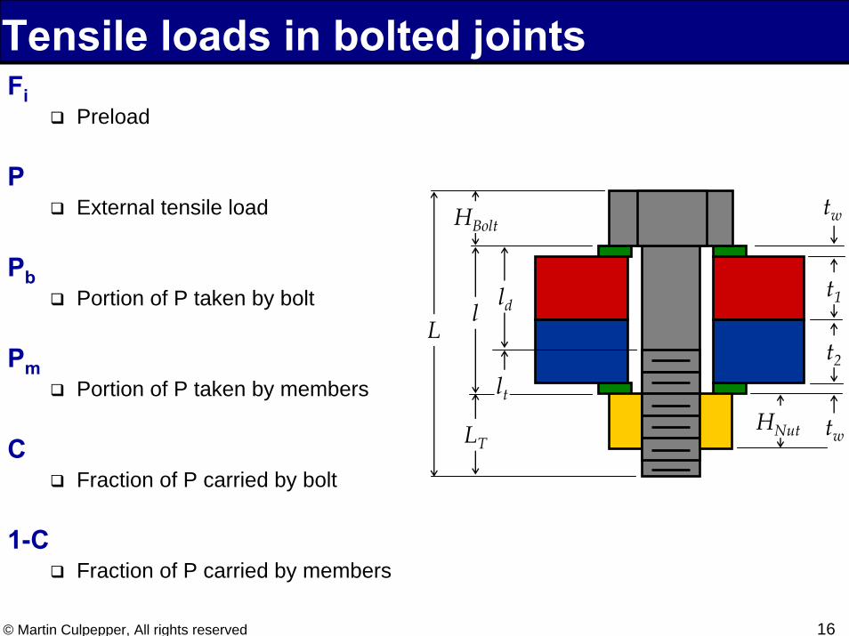
Tensile loads in bolted jointsFi
Preload
PExternal tensile load
PbPortion of P taken by bolt
PmPortion of P taken by members
CFraction of P carried by bolt
1-CFraction of P carried by members
l
tw
tw
HBolt
LT
L
t1
t2
HNut
lt
ld
17© Martin Culpepper, All rights reserved
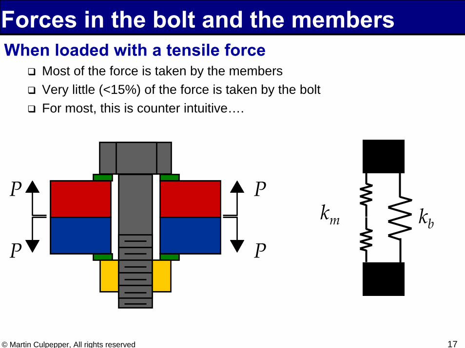
Forces in the bolt and the membersWhen loaded with a tensile force
Most of the force is taken by the membersVery little (<15%) of the force is taken by the boltFor most, this is counter intuitive….
P
PP
Pkm kb
18© Martin Culpepper, All rights reserved
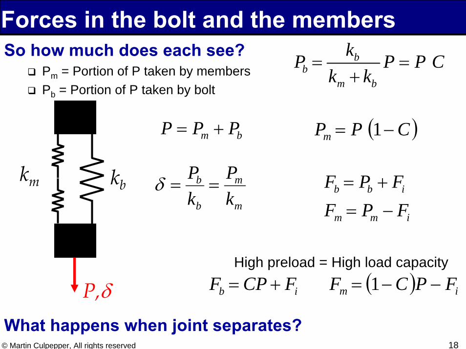
Forces in the bolt and the membersSo how much does each see?
Pm = Portion of P taken by membersPb = Portion of P taken by bolt
What happens when joint separates?
km kbm
m
b
b
kP
kP
==δ
bm PPP +=
bb
m b
kP P P Ck k
= =+
( )CPPm −= 1
P,δHigh preload = High load capacity
( ) im FPCF −−= 1
b b i
m m i
F P FF P F= +
= −
b iF CP F= +
19© Martin Culpepper, All rights reserved
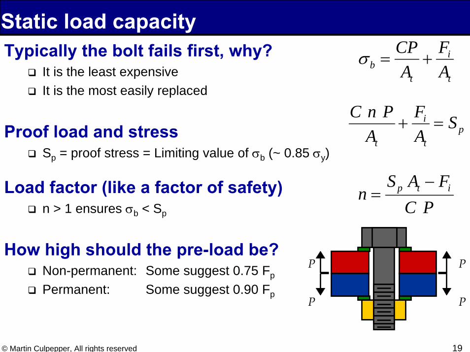
Static load capacityTypically the bolt fails first, why?
It is the least expensiveIt is the most easily replaced
Proof load and stressSp = proof stress = Limiting value of σb (~ 0.85 σy)
Load factor (like a factor of safety)n > 1 ensures σb < Sp
How high should the pre-load be?Non-permanent: Some suggest 0.75 Fp
Permanent: Some suggest 0.90 Fp
P
PP
P
t
i
tb A
FA
CP+=σ
pt
i
t
SAF
APnC
=+
PCFAS
n itp −=
20© Martin Culpepper, All rights reserved
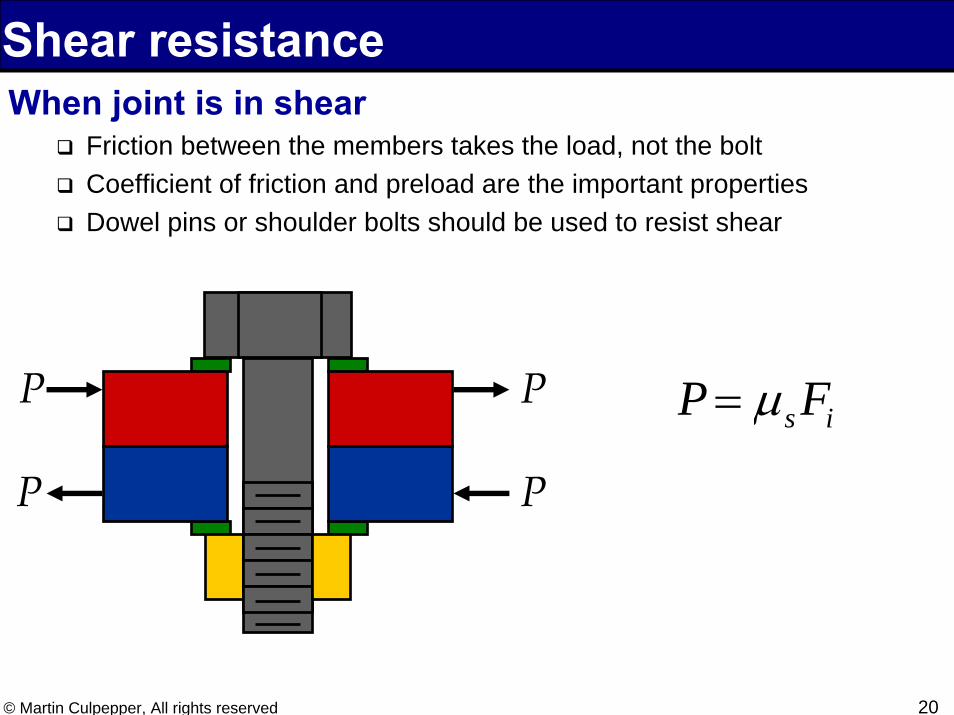
Shear resistanceWhen joint is in shear
Friction between the members takes the load, not the boltCoefficient of friction and preload are the important propertiesDowel pins or shoulder bolts should be used to resist shear
P
PP
Ps iP Fμ=
Torque,friction, preload
22© Martin Culpepper, All rights reserved
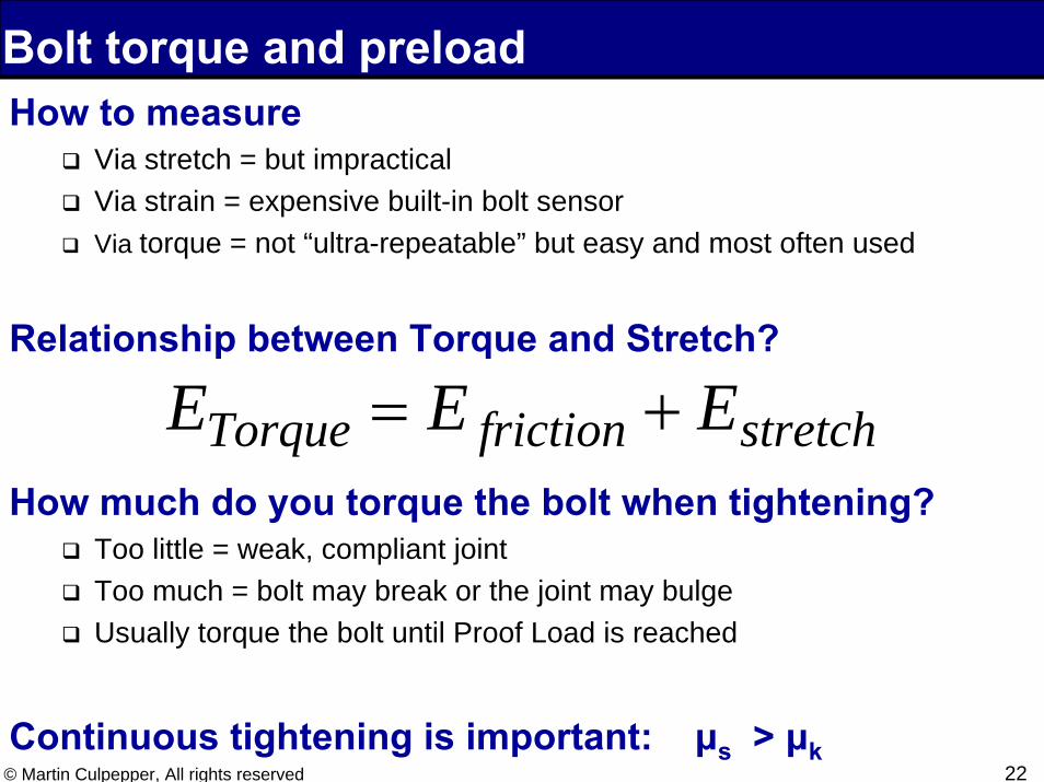
How to measureVia stretch = but impracticalVia strain = expensive built-in bolt sensorVia torque = not “ultra-repeatable” but easy and most often used
Relationship between Torque and Stretch?
How much do you torque the bolt when tightening?Too little = weak, compliant jointToo much = bolt may break or the joint may bulgeUsually torque the bolt until Proof Load is reached
Continuous tightening is important: μs > μk
Bolt torque and preload
stretchfrictionTorque EEE +=

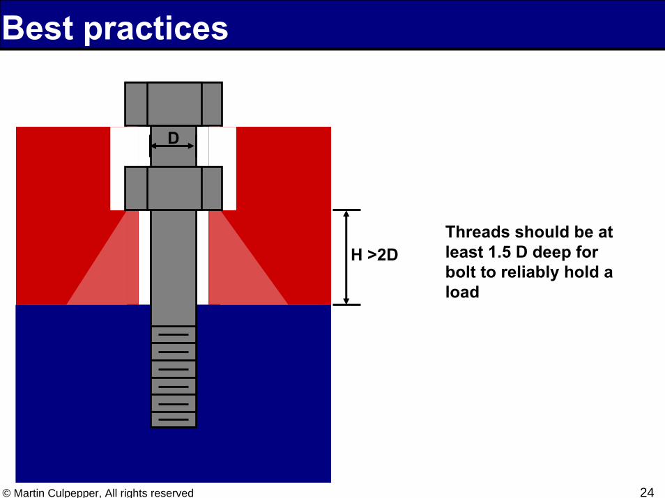
Best practices
24© Martin Culpepper, All rights reserved
D
H >2DThreads should be at least 1.5 D deep for bolt to reliably hold a load
Best practices
25© Martin Culpepper, All rights reserved
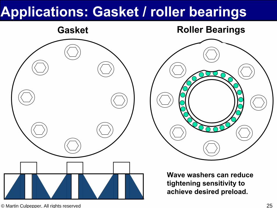
Gasket Roller Bearings
Wave washers can reduce tightening sensitivity to achieve desired preload.
Applications: Gasket / roller bearings

Exercise
27© Martin Culpepper, All rights reserved
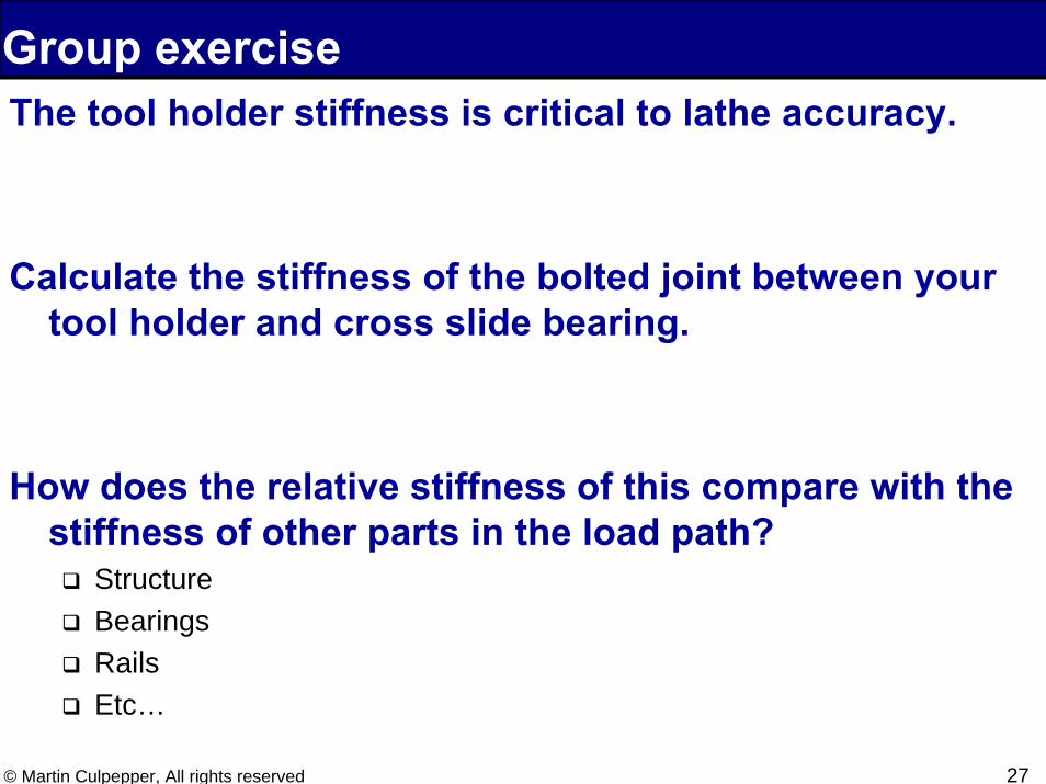
Group exerciseThe tool holder stiffness is critical to lathe accuracy.
Calculate the stiffness of the bolted joint between your tool holder and cross slide bearing.
How does the relative stiffness of this compare with the stiffness of other parts in the load path?
StructureBearingsRailsEtc…
28© Martin Culpepper, All rights reserved
Preventing Bolts from Coming Loose
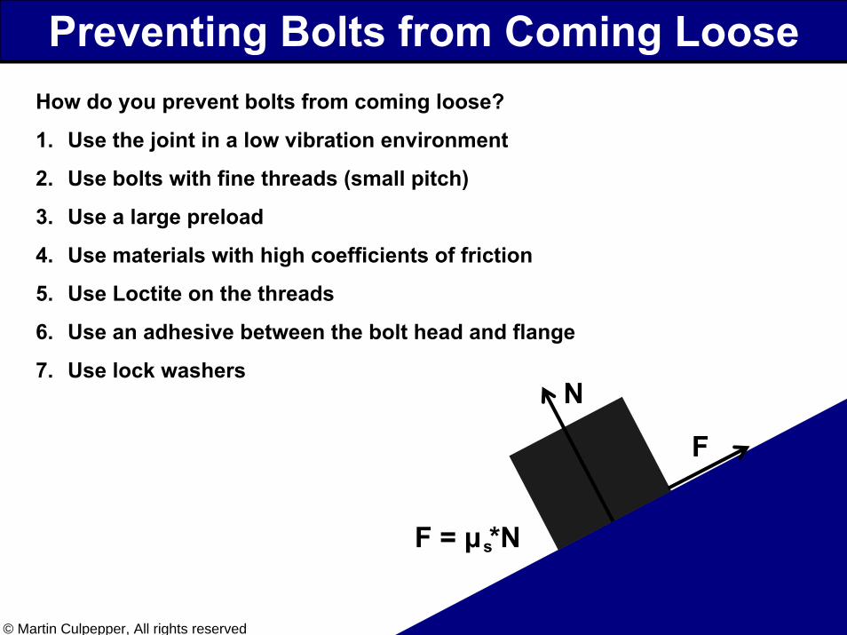
N
F
F = μ *Ns
How do you prevent bolts from coming loose?
1. Use the joint in a low vibration environment
2. Use bolts with fine threads (small pitch)
3. Use a large preload
4. Use materials with high coefficients of friction
5. Use Loctite on the threads
6. Use an adhesive between the bolt head and flange
7. Use lock washers
29© Martin Culpepper, All rights reserved
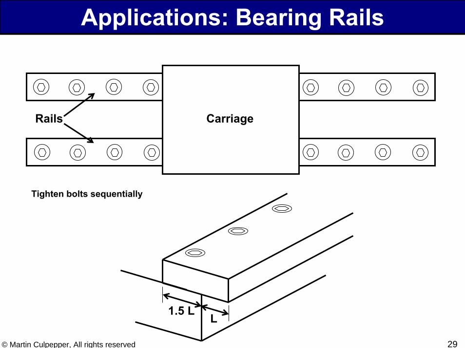
Applications: Bearing Rails
CarriageRails
L1.5 L
Tighten bolts sequentially
30© Martin Culpepper, All rights reserved
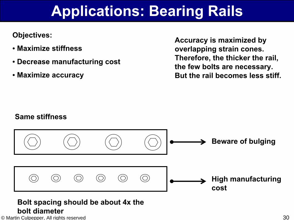
Applications: Bearing RailsObjectives:
• Maximize stiffness
• Decrease manufacturing cost
• Maximize accuracy
Same stiffness
Bolt spacing should be about 4x the bolt diameter
Accuracy is maximized by overlapping strain cones. Therefore, the thicker the rail, the few bolts are necessary. But the rail becomes less stiff.
Beware of bulging
High manufacturing cost