ME 331: Design of Machine Elements - Notesvillagenotesvillage.com/upload/ME331.pdfME 331: Design of...
140
ME 331: Design of Machine Elements Dr. H. Hirani Associate Professor Department of Mechanical Engineering 28 12, 25 2 Quiz 10% 3 / 4 80% of End-Sem September: 20, 21, 25,27 October: 4,5,9,11,16,18,19,23,26, 30 November: 1, 6, 13, 15, 16 Remark Lecture Contact Time: 16.30 to 17.30 Hours --- Monday to Friday. References: 1. http://www.mech.uwa.edu.au/DANotes/intro/contents.html 2. Machine Design: An Integrated Approach.. R. L. Norton
Transcript of ME 331: Design of Machine Elements - Notesvillagenotesvillage.com/upload/ME331.pdfME 331: Design of...

ME 331: Design of Machine Elements
Dr. H. HiraniAssociate ProfessorDepartment of Mechanical Engineering
2812, 252
Quiz10%3 / 4
80% of End-Sem
September: 20, 21, 25,27
October: 4,5,9,11,16,18,19,23,26, 30
November: 1, 6, 13, 15, 16
RemarkLecture
Contact Time: 16.30 to 17.30 Hours --- Monday to Friday.
References:
1. http://www.mech.uwa.edu.au/DANotes/intro/contents.html
2. Machine Design: An Integrated Approach.. R. L. Norton
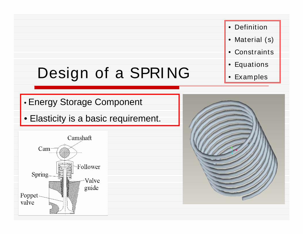
Design of a SPRING
• Definition
• Material (s)
• Constraints
• Equations
• Examples
• Energy Storage Component
• Elasticity is a basic requirement.

• Energy Storage Component
• Elasticity is a basic requirement.
• Requirement of relatively large deformation.
P
P

DesignService condition
FunctionCost
MaterialsProperties
AvailabilityCost
ProcessingEquipment sel.
Influence of prop.Cost
• “CONCURRENT ENG.” MAT. & PROCESSES CONSIDERATION AT EARLIER STAGE
Material choice cannot be made independently of the choice of process by which material is to be machined, joined, or treated.

Property bar-chartsMetals Polymers Ceramics Composites
PEEK
PP
PTFE
WC
Alumina
Glass
CFRP
GFRP
Fibreboard
Y ou n
g ’s
mod
ulus
, GPa
Steel
Copper
Lead
Zinc
Aluminum
orSE /=
Covalent bond is stiff (S= 20 –200 N/m) Metallic & Ionic (15-100 N/m)
Polymers having Van der Waals bonds (0.5 to 2 N/m). r0~ 3*10-10m)
ATOMIC SIZE
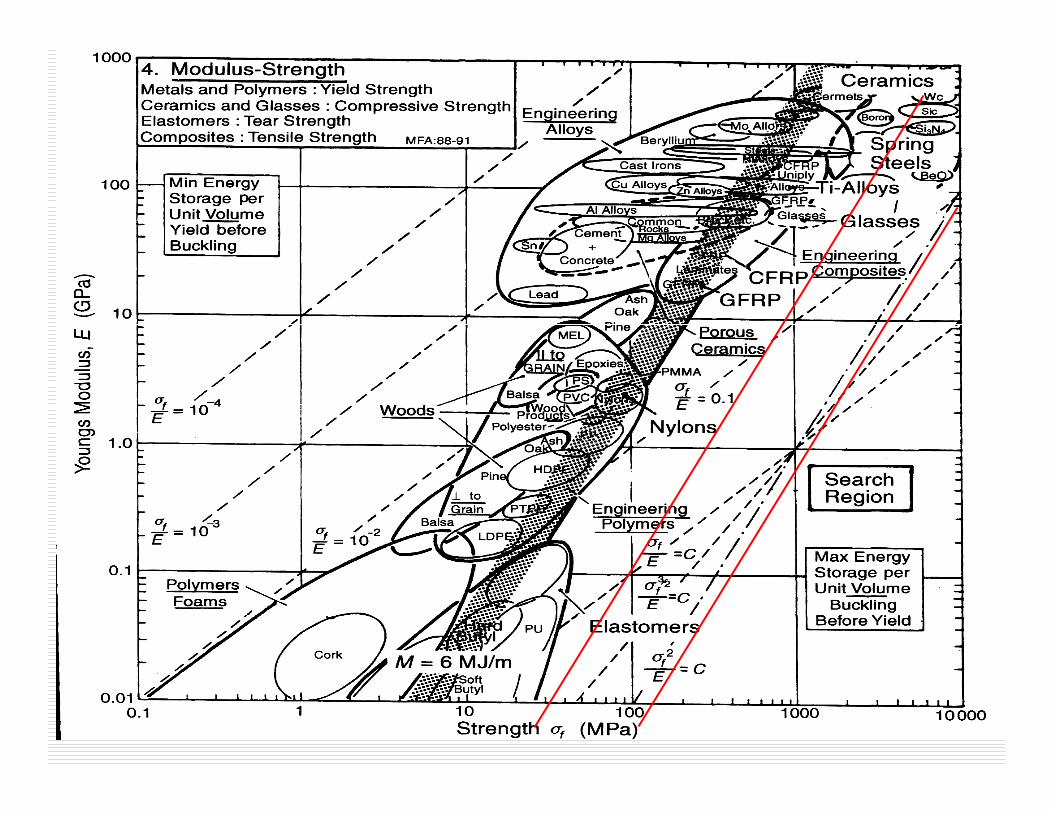
EWV
2σ∝
? ELASTIC ENERGY/VOLUME

Better than spring steel10-30Rubber
Economic & easily shaped1.5-2.5Nylon
--10-12GFRP
Comparable in performance with steel, expensive
15-20CFRP
Expensive, corrosion resistant
15-20Ti alloys
Traditional choice: easily formed and heat treated.
15-25Spring steel
Brittle in tension; good only in compression
10-100Ceramics
CommentMATERIAL ( )32 .... mMJEM fσ=

Natural frequency
ρπ
ρππ
DNgk
df
DNdW
Wgkf
n
n
14
21
2
=⇒
=
=E
WV
2σ∝
EWV
2σ∝ E
Ww ρσ 2
∝
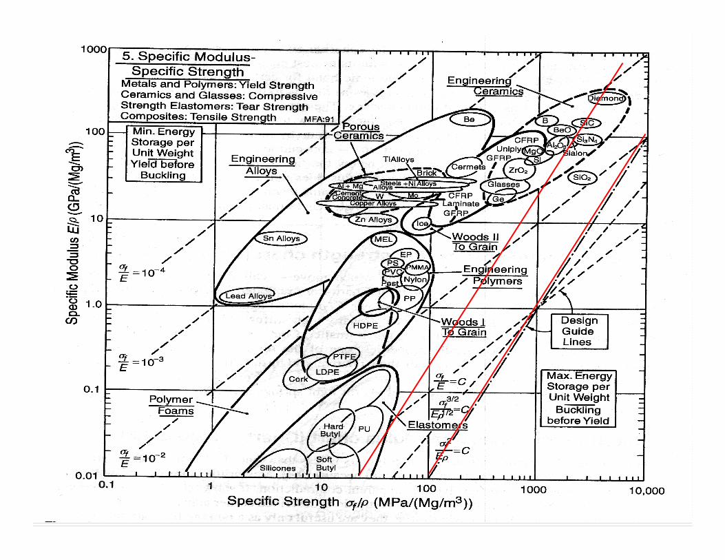

? ELASTIC ENERGY/COST ECM
m
f
ρσ 2
=
EM f
ρσ 2
=
Better than spring steel10-30, 10-30Rubber
Economic & easily shaped1.5-2.5, 1.5-2Nylon
--10-12, 3-5GFRP
Comparable in performance with steel, expensive
15-20, 4-8CFRP
Expensive, corrosion resistant15-20, 2-3Ti alloys
Traditional choice: easily formed and heat treated.
15-25, 2-3Spring steel
Brittle in tension; good only in compression
10-100, 5-50Ceramics
CommentMATERIAL EM f2σ=

Rubber Springs
Hooke’s law?Stiffness increases with increase in deflection.
Temperature dependence. Useful if damping/cushioning is required? Often hybridized with metals. …. Requires detailed analysis.
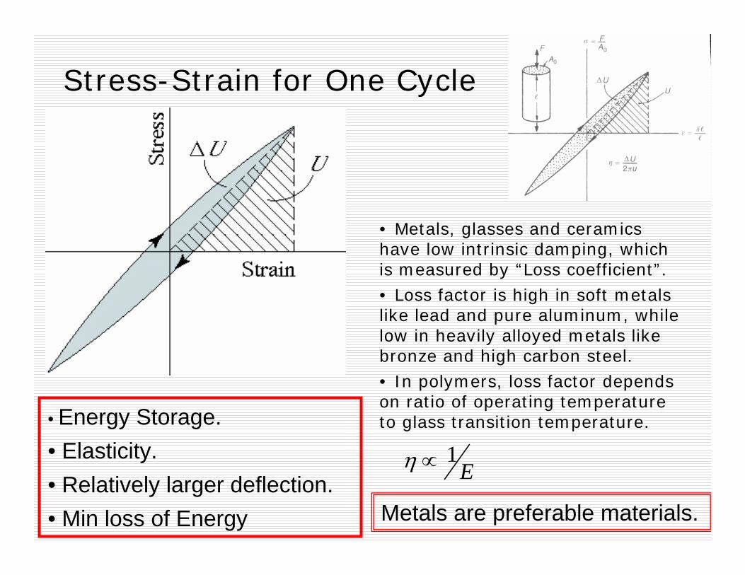
Stress-Strain for One Cycle
• Energy Storage.• Elasticity.• Relatively larger deflection.• Min loss of Energy Metals are preferable materials.
• Metals, glasses and ceramics have low intrinsic damping, which is measured by “Loss coefficient”.• Loss factor is high in soft metals like lead and pure aluminum, while low in heavily alloyed metals like bronze and high carbon steel. • In polymers, loss factor depends on ratio of operating temperature to glass transition temperature.
E1∝η


Home Assignment I
List the material (s) needed for a Spring aiming to maximize energy storage, minimize energy loss and density.

Relative Cost
1.0
2.6
1.3
3.1
-
7.6
4.0
---
8.0
27.0
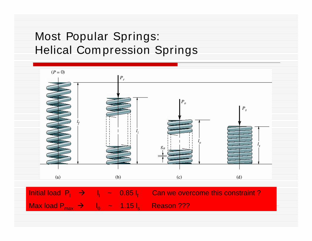
Most Popular Springs: Helical Compression Springs
Initial load Pl ll ~ 0.85 lf Can we overcome this constraint ?
Max load Pmax l0 ~ 1.15 ls Reason ???

Force vs. Deflection δ∝P
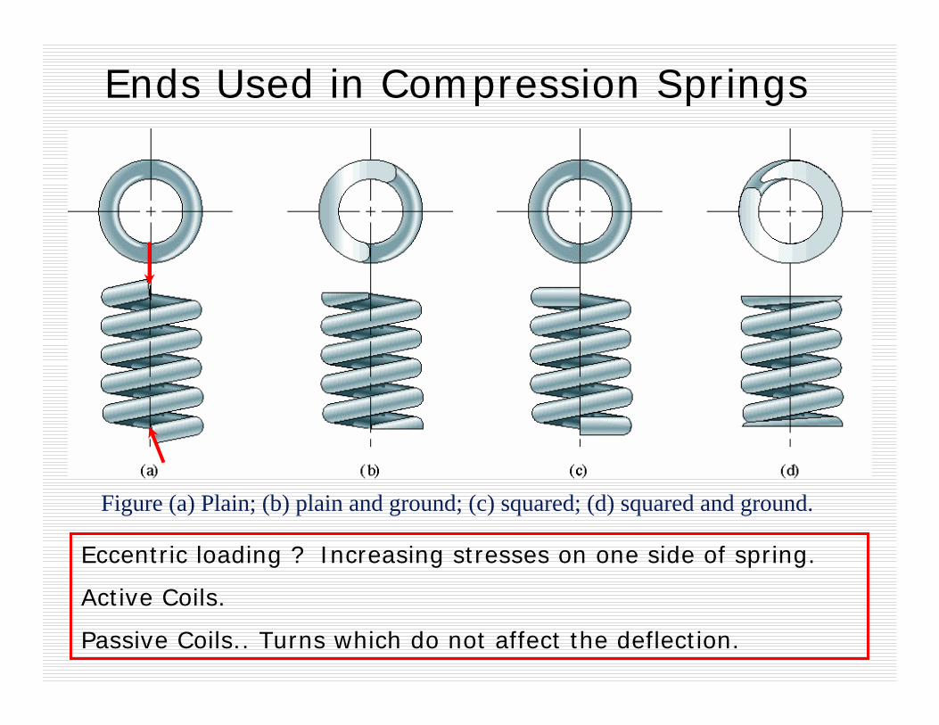
Ends Used in Compression Springs
Figure (a) Plain; (b) plain and ground; (c) squared; (d) squared and ground.
Eccentric loading ? Increasing stresses on one side of spring.
Active Coils.
Passive Coils.. Turns which do not affect the deflection.

Force & Torque
αcosPαsinP
αcosP
αsinPαcosP
αcosP
0sin cos 10 If
≈≈≤
ααα
PPPo
Due to compressive loading, Helical Compression Spring will be subjected to “Direct Shear” and “Torsion”.
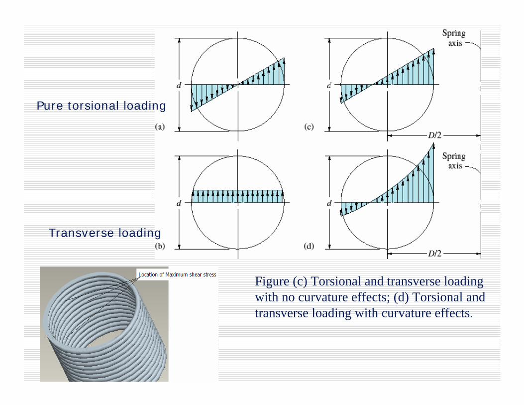
Figure (c) Torsional and transverse loading with no curvature effects; (d) Torsional and transverse loading with curvature effects.
Pure torsional loading
Transverse loading

⎟⎠⎞
⎜⎝⎛ +==
⎟⎠⎞
⎜⎝⎛ +=
+=
+=
+=
Ckk
dPC
CdPC
dP
ddCdP
dP
ddDP
AP
JTr
ss5.01 ;8
2118
4*.8
4/)32/()2/(*)2/.(
2
2
24
24
max
π
π
ππ
ππ
τ
Mathematical FormulationStressStrength >
max ,
τys
sS
NfactorSafety =
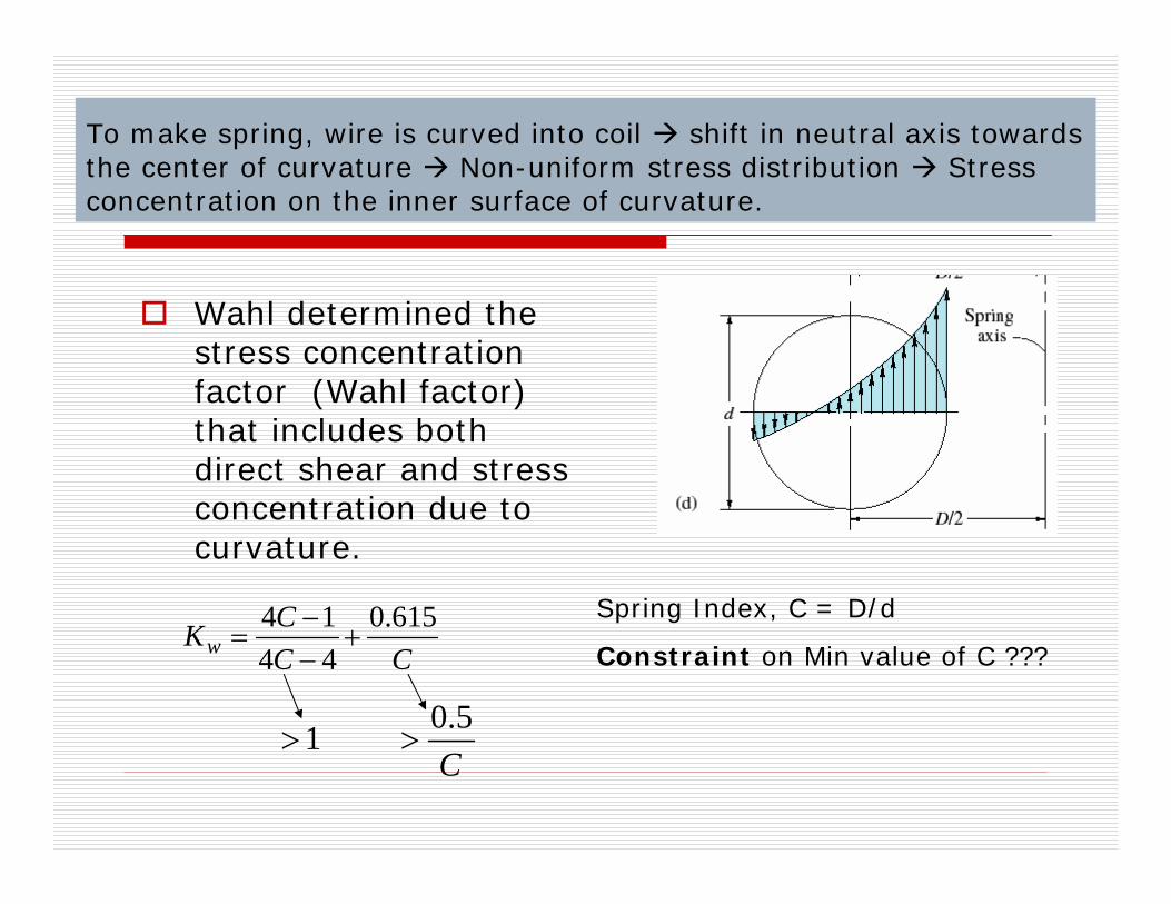
Wahl determined the stress concentration factor (Wahl factor) that includes both direct shear and stress concentration due to curvature.
CCCKw
615.04414+
−−
=
C5.0 1 >>
To make spring, wire is curved into coil shift in neutral axis towards the center of curvature Non-uniform stress distribution Stress concentration on the inner surface of curvature.
Spring Index, C = D/d
Constraint on Min value of C ???

Spring Stress Factor
1.3111.2531.2131.1841.1621.1451.1311.119
1.11.0831.0711.0631.0561.0501.0451.042
56789101112
KwKsC (=D/d)

Under static load, yielding is the failure criterion.
Ductile materials yields locally and stress concentration is negligible.
Under dynamic load, the failure will be fatigue and stress concentration due to curvature will play important role.
load fatiguefor 615.04414
load staticfor 5.01
CCCk
Ck
c
c
+−−
=
⎟⎠⎞
⎜⎝⎛ +=
ckdPC
2max8π
τ =

1.32.12.43.23.84.24.87.58.59.5
0.110.140.180.220.280.350.450.550.650.70.91.11.41.82.22.8
0.100.120.160.200.250.300.400.500.600.801.01.21.62.02.53.0
Third Preference
Second Preference
First Preference
Preferred Diameters for Spring Steel Wire, mm
4.05.06.08.010.012.014.016.0
First Preference
3.54.55.56.57.09.011.013.015.0
Second Preference
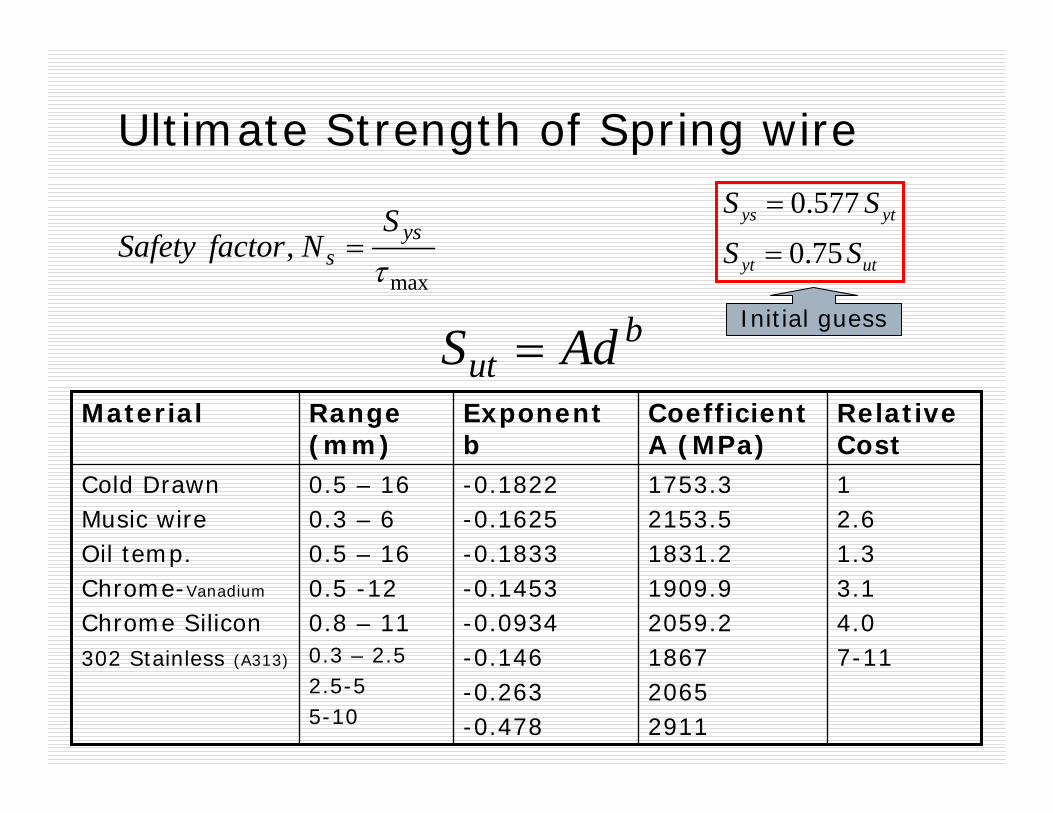
Ultimate Strength of Spring wire
utyt
ytys
SS
SS
75.0
577.0
=
=
max ,
τys
sS
NfactorSafety =
but AdS =
Initial guess
12.61.33.14.07-11
1753.32153.51831.21909.92059.2186720652911
-0.1822-0.1625-0.1833-0.1453-0.0934-0.146-0.263-0.478
0.5 – 160.3 – 60.5 – 160.5 -120.8 – 110.3 – 2.52.5-55-10
Cold DrawnMusic wireOil temp.Chrome-Vanadium
Chrome Silicon302 Stainless (A313)
Relative Cost
Coefficient A (MPa)
Exponent b
Range (mm)
Material
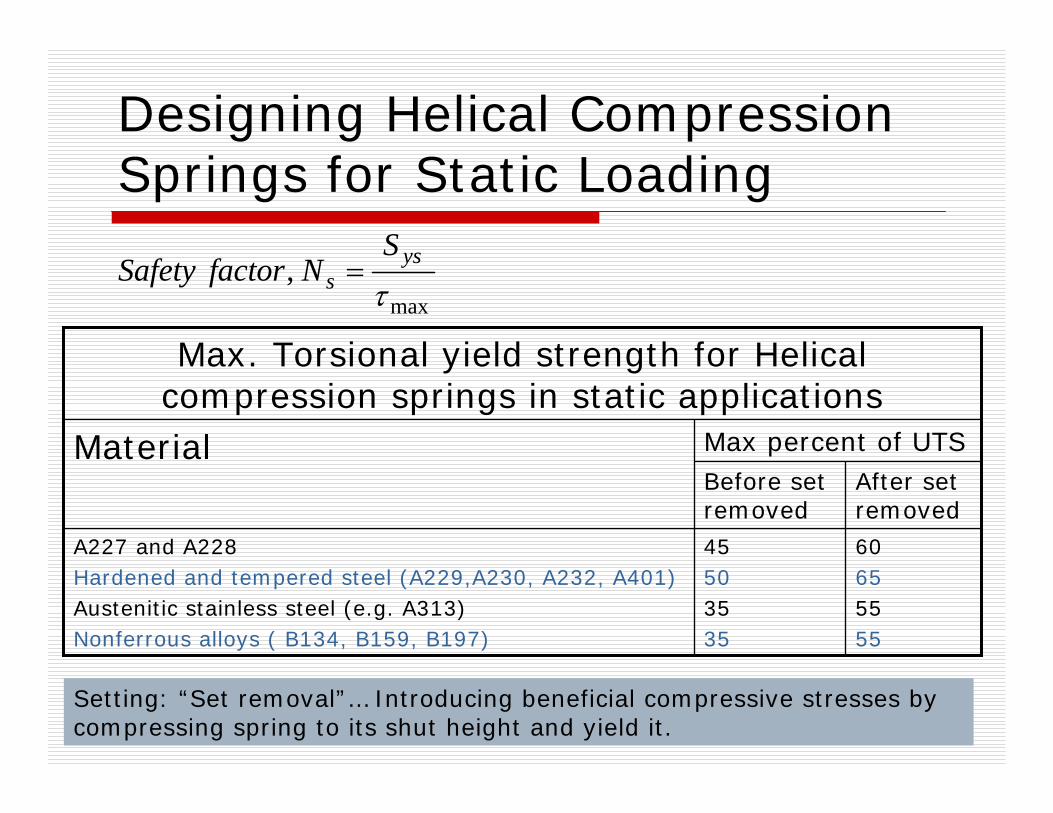
Designing Helical Compression Springs for Static Loading
max ,
τys
sS
NfactorSafety =
60655555
45503535
A227 and A228Hardened and tempered steel (A229,A230, A232, A401)Austenitic stainless steel (e.g. A313)Nonferrous alloys ( B134, B159, B197)
After set removed
Before set removed
Max percent of UTSMaterial
Max. Torsional yield strength for Helical compression springs in static applications
Setting: “Set removal”… Introducing beneficial compressive stresses by compressing spring to its shut height and yield it.
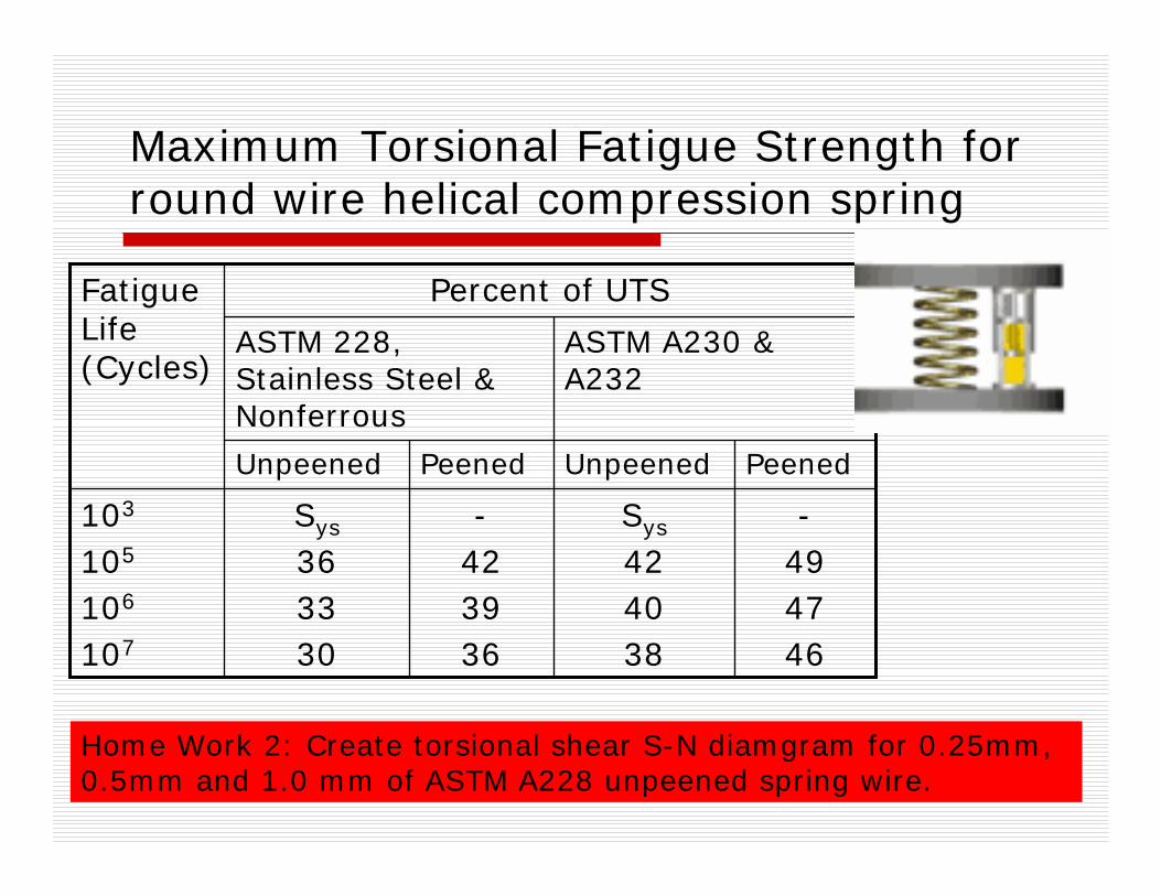
Maximum Torsional Fatigue Strength for round wire helical compression spring
-494746
Sys
424038
-423936
Sys
363330
103
105
106
107
PeenedUnpeenedPeenedUnpeened
ASTM A230 & A232
ASTM 228, Stainless Steel & Nonferrous
Percent of UTSFatigue Life (Cycles)
Home Work 2: Create torsional shear S-N diamgram for 0.25mm, 0.5mm and 1.0 mm of ASTM A228 unpeened spring wire.

Ex: Design a cold drawn steel wire helical compression spring, having minimum possible spring index. Static
axial load = 500 N. Min value of factor of safety = 1.2
Step 1: Stress factor ….. Ks
Step 2: Strength & Stress. Trial 1: d=1mm
Trial 2: d =2mm
Trial 3: d=3mm
Strength 789 MPa
Strength 695 MPa
Strength 646 MPa
Stress = 1751 MPa.
Stress = 7003 MPa.
Stress = 778 MPa.
Final Design, d=4 mm, Stress = 438 MPa, Strength = 613 MPa, S.F. = 613/438
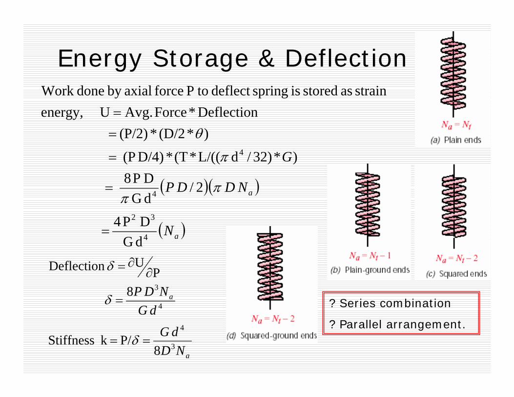
Energy Storage & Deflection
( )( )
( )a
a
N
NDDP
G
4
32
4
4
dGD P4
2/dGD P8
)*)32/dL/((*(T* D/4)(P ) * (D/2 * (P/2)
Deflection * Force Avg. Uenergy,strain as stored is springdeflect toP force axialby doneWork
=
=
=
==
ππ
π
θ
a
a
NDdG
dGNDP
3
4
4
3
8P/ k Stiffness
8
PU Deflection
==
=
∂∂=
δ
δ
δ
? Series combination
? Parallel arrangement.

Ex: Design a cold drawn steel wire helical compression spring, having minimum possible spring index. Static (max.) axial load = 500 N. Min value of factor of safety = 1.1 and Stiffness 25 N/mm. G=80000 N/mm2. Assume spring has square and ground ends
Step 1: Stress factor ….. Ks
Step 2: Strength & Stress. d=3.5mm
Stress = 572 MPa, Strength = 638 MPa, S.F. = 638/572
aNDdG3
4
8P/ k Stiffness == δ
Known values:
G = 80 GPa
D = 5*3.5 = 17.5mm
d = 3.5 mm
k = 25 N/mm
Total No. of Turns = ????
Free length of spring = ???

Homework 3: Determine the deflection of springs shown in Figure. Axial load = 2000 N
000,80,15,3,12N
2 Spring
000,100,30,6,12N
1 Spring
a
a
====
====
GmmDmmd
GmmDmmd
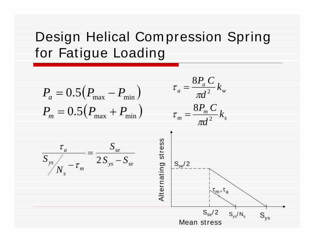
Design Helical Compression Spring for Fatigue Loading
( )( )minmax
minmax
5.05.0
PPPPPP
m
a
+=−=
sm
m
wa
a
kd
CP
kd
CP
2
2
8
8
πτ
πτ
=
=
Mean stress
Alter
nat
ing s
tres
s
τm,τa
SysSys/Ns
Sse/2
seys
se
ms
ys
a
SSS
NS −
=− 2τ
τ
Sse/2

Ex: The exhaust valve system of diesel engine is shown in Figure. The diameter of valve seat is 30mm and the suction pressure in the cylinder is 0.05 MPa. The mass of valve body is 70 gm. Max. required valve lift =10 mm. Spring stiffness = 10 N/mm. C = 7. Design this spring for factor of safety greater than 1.25. Spring Mat. = Music wire.
Min load ???Max. Load ???
( )( )minmax
minmax
5.05.0
PPPPPP
m
a
+=−=
sm
m
wa
a
kd
CP
kd
CP
2
2
8
8
πτ
πτ
=
=
seys
se
ms
ys
a
SSS
NS −
=− 2τ
τ
Homework 4: A helical compression unpeenedspring, made of ASTM A228, is preloaded with 25 N axial force. The maximum operating force during load cycle is 100 N. Assume spring index = 6, factor of safety ≥1.25. Determine wire diameter for spring life = 107 cycles.
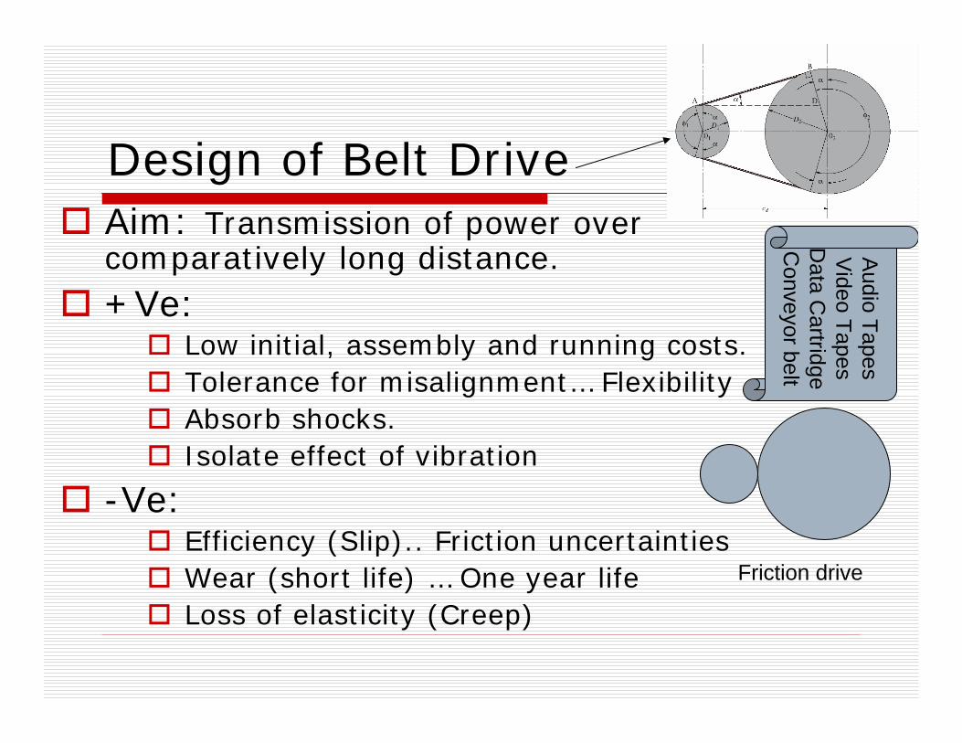
Design of Belt DriveAim: Transmission of power over comparatively long distance.+Ve:
Low initial, assembly and running costs. Tolerance for misalignment… FlexibilityAbsorb shocks. Isolate effect of vibration
-Ve: Efficiency (Slip).. Friction uncertaintiesWear (short life) … One year life Loss of elasticity (Creep)
Friction drive
Audio Tapes
Video Tapes
Data C
artridgeC
onveyor belt

Toothed wheel
p > 2Timing
Grooved/ Sheaves
ht =8 to 19V
Groovedd=3 to 20Round
Crowned
t=0.75 -5
Flat
Required PulleySize range (mm)
Cross section
Belt Type
Note: Time belt uses positive drive mechanism, while other belt drives use friction drive mechanism. Time belt drive does not require any initial tension. Teeth make it possible to run at any speed.
d
ht
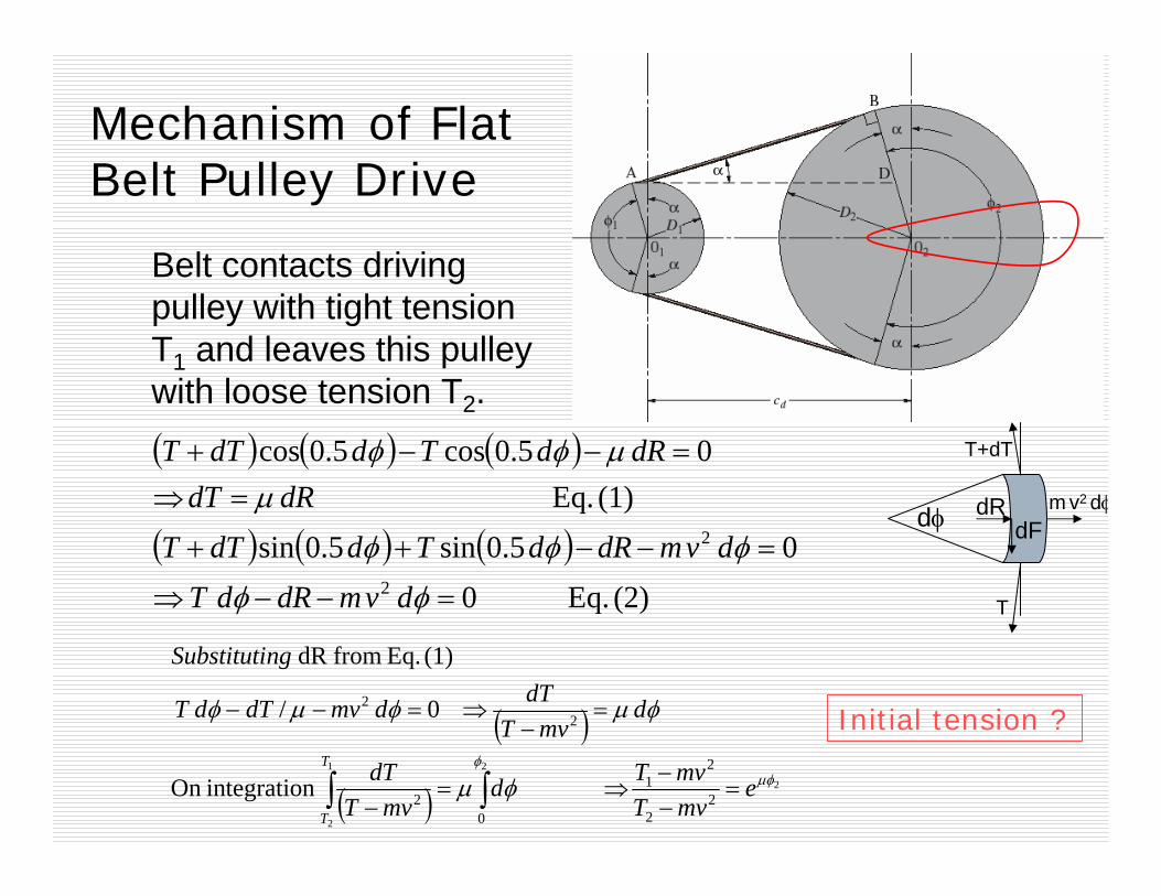
Mechanism of Flat Belt Pulley Drive
( ) ( ) ( )
( ) ( ) ( )(2) Eq. 0
05.0sin5.0sin(1) Eq.
05.0cos5.0cos
2
2
=−−⇒
=−−++
=⇒=−−+
φφ
φφφ
μμφφ
dvmdRdTdvmdRdTddTT
dRdTdRdTddTT
dφ
T
T+dT
dRdF
( )
( )2
21
2
22
21
02
22
n integratioOn
0/
(1)Eq.from dR
μφφ
φμ
φμφμφ
emvTmvTd
mvTdT
dmvT
dTdmvdTdT
ngSubstituti
T
T
=−−
⇒=−
=−
⇒=−−
∫∫
m v2 dφ
Belt contacts driving pulley with tight tension T1 and leaves this pulley with loose tension T2.
Initial tension ?

Open Flat Belt
212
2
2
1
121
)5.05.0(
22
2sin
DDCAB
CDD
d
d
−−=
+=−=
⎟⎟⎠
⎞⎜⎜⎝
⎛ −= −
απφαπφ
α
( ) ( ) ( )( ) ( ) ( )
( ) ( ) ( ) ⎟⎟⎠
⎞⎜⎜⎝
⎛ −−+++−−=
−+++−−=
++−+−−=
++=
−
dd
d
d
CDDDDDDDDCL
DDDDDDCL
DDDDCL
DDABL
2sin5.04 or,
5.04 or,
25.025.04 or,
5.05.02 Length,Belt
1211221
212
2
12212
122
212
122
2211
π
απ
απαπ
φφ
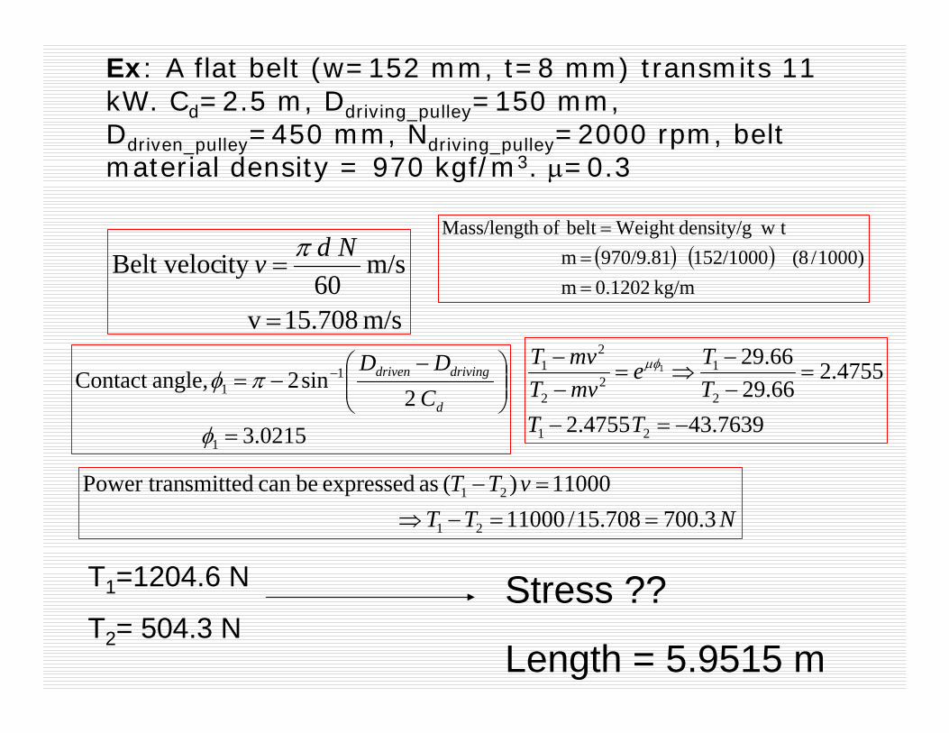
Ex: A flat belt (w=152 mm, t=8 mm) transmits 11 kW. Cd=2.5 m, Ddriving_pulley=150 mm, Ddriven_pulley=450 mm, Ndriving_pulley=2000 rpm, belt material density = 970 kgf/m3. μ=0.3
m/s15.708 v
m/s 60
ity Belt veloc
=
=Ndv π
NTTvTT
3.700708.15/11000 11000)( as expressed becan smittedPower tran
21
21
==−⇒=−
( ) ( )kg/m 0.1202 m
)1000/8(152/1000 970/9.81 m t wdensity/g Weight belt ofh Mass/lengt
===
0215.3 2
sin2 angle,Contact
1
11
=
⎟⎟⎠
⎞⎜⎜⎝
⎛ −−= −
φ
πφd
drivingdriven
CDD
7639.434755.2
4755.266.2966.29
21
2
12
2
21 1
−=−
=−−
⇒=−−
TTTTe
mvTmvT μφ
T1=1204.6 N
T2= 504.3 NStress ??
Length = 5.9515 m

Commercial Flat Belts
100112125152180200
7690100112125152200224
25, 32,40, 4450, 6376, 90100112125140152
2532404450637690100
6 Ply5 Ply4 Ply3 Ply
Width (mm) of High Speed (Light to Medium duty: 2.3*V W/mm per ply) belt
200250305355400
112125152180200250
76100112125152180250
40, 4450, 637690100112125152
2540506376
8 Ply6 Ply5 Ply4 Ply3 Ply
Width (mm) of FORT (Heavy duty: 2.89*V W/mm per ply) belt
Correct Initial tension – Belt shorter than calculated length.
Belt of 3 Plies --- ----15 mm per meter belt length
Belt of 4 to 6 Plies– 10mm per meter belt length
Belt of 8 Plies ------- 5 mm per meter belt length

Commercial Flat Belts….cont
….….……
6 Ply5 Ply4 Ply3 Ply
Width (mm) of High Speed (Light to Medium duty: 2.3*V W/mm per ply)
……………
8 Ply6 Ply5 Ply4 Ply3 Ply
Width (mm) of FORT (Heavy duty: 2.89*V W/mm per ply)
1.01.2
1.3
1.5
1. Normal load2. Steady load, e.g. Centrifugal pump, fans,
machine tools, conveyors.3. Intermittent load, e,g, heavy duty fans,
blowers, compressors, reciprocating pumps, line shafts
4. Shock load, e.g. vacuum pumps, rolling mills, hammers, grinders
Load Correction FactorType of Load
0.97
190
0.941.01.041.081.131.191.261.33Contact factor
200180170160150140130120Arc of contact
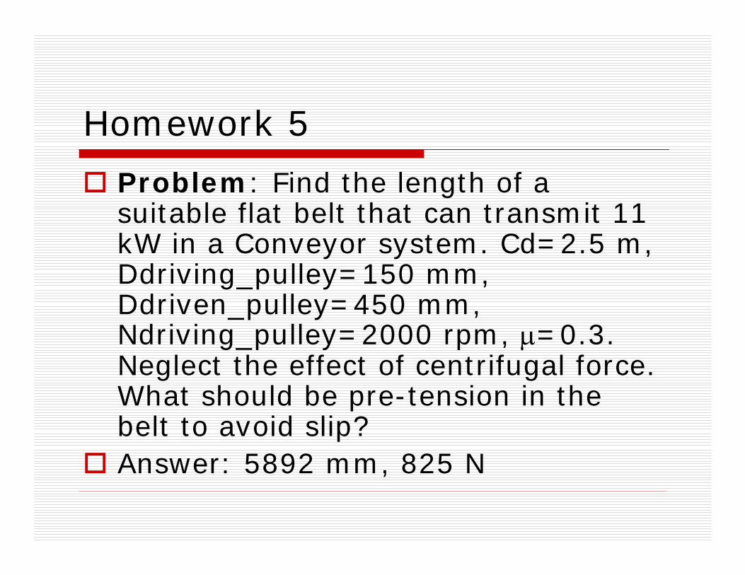
Homework 5
Problem: Find the length of a suitable flat belt that can transmit 11 kW in a Conveyor system. Cd=2.5 m, Ddriving_pulley=150 mm, Ddriven_pulley=450 mm, Ndriving_pulley=2000 rpm, μ=0.3. Neglect the effect of centrifugal force. What should be pre-tension in the belt to avoid slip? Answer: 5892 mm, 825 N
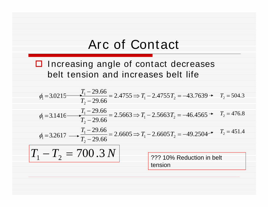
Arc of ContactIncreasing angle of contact decreases belt tension and increases belt life
NTT 3.70021 =−
2617.3
1416.3
0215.3
1
1
1
=
=
=
φ
φ
φ
2504.496605.26605.266.2966.29
4565.465663.25663.266.2966.29
7639.434755.24755.266.2966.29
212
1
212
1
212
1
−=−⇒=−−
−=−⇒=−−
−=−⇒=−−
TTTT
TTTT
TTTT
4.451
8.476
3.504
2
2
2
=
=
=
T
T
T
??? 10% Reduction in belt tension
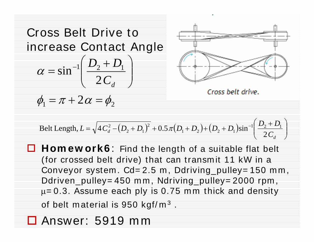
Cross Belt Drive to increase Contact Angle
21
121
22
sin
φαπφ
α
=+=
⎟⎟⎠
⎞⎜⎜⎝
⎛ += −
dCDD
( ) ( ) ( ) ⎟⎟⎠
⎞⎜⎜⎝
⎛ ++++++−= −
dd C
DDDDDDDDCL2
sin5.04 Length,Belt 1211221
212
2 π
Homework6: Find the length of a suitable flat belt (for crossed belt drive) that can transmit 11 kW in a Conveyor system. Cd=2.5 m, Ddriving_pulley=150 mm, Ddriven_pulley=450 mm, Ndriving_pulley=2000 rpm, μ=0.3. Assume each ply is 0.75 mm thick and density
of belt material is 950 kgf/m3 .
Answer: 5919 mm
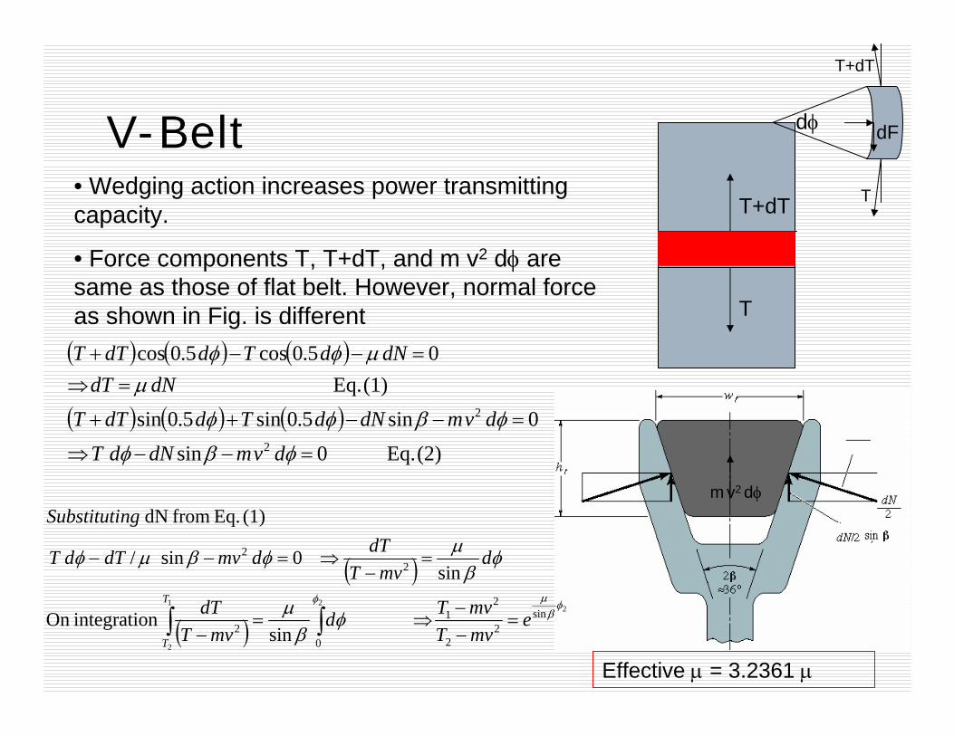
V-Belt
( ) ( ) ( )
( ) ( ) ( )(2) Eq. 0sin
0sin5.0sin5.0sin(1) Eq.
05.0cos5.0cos
2
2
=−−⇒
=−−++
=⇒=−−+
φβφ
φβφφ
μμφφ
dvmdNdTdvmdNdTddTT
dNdTdNdTddTT
T+dT
T
m v2 dφ
• Wedging action increases power transmitting capacity.
• Force components T, T+dT, and m v2 dφ are same as those of flat belt. However, normal force as shown in Fig. is different
( )
( )2
21
2
sin2
2
21
02
22
sin
n integratioOn
sin0sin/
(1) Eq. from dN
φβ
μφ
φβ
μ
φβ
μφβμφ
emvTmvTd
mvTdT
dmvT
dTdmvdTdT
ngSubstituti
T
T
=−−
⇒=−
=−
⇒=−−
∫∫
Effective μ = 3.2361 μ
dφ
T
T+dT
dF

Data on Standard V-belt Sections
0.1060.1890.3430.596-
811141923
1317223238
75125200355500
.75-7.52-157.5-7522-15030-190
ABCDE
Weight per meter, kgf
ht , mm
Wt , mm
Recommended min pulley pitch dia, mm
Drive load, kW
Cross section Symbol
• Only certain discrete standard pitch lengths are manufactured. • Only certain recommended pitch pulley diameters are preferred. • A special pulley may be manufactured of course - but would cost more than a mass- produced commercial product.
Groove angle of pulley is made somewhat smaller than belt-section angle..
Catalogue A
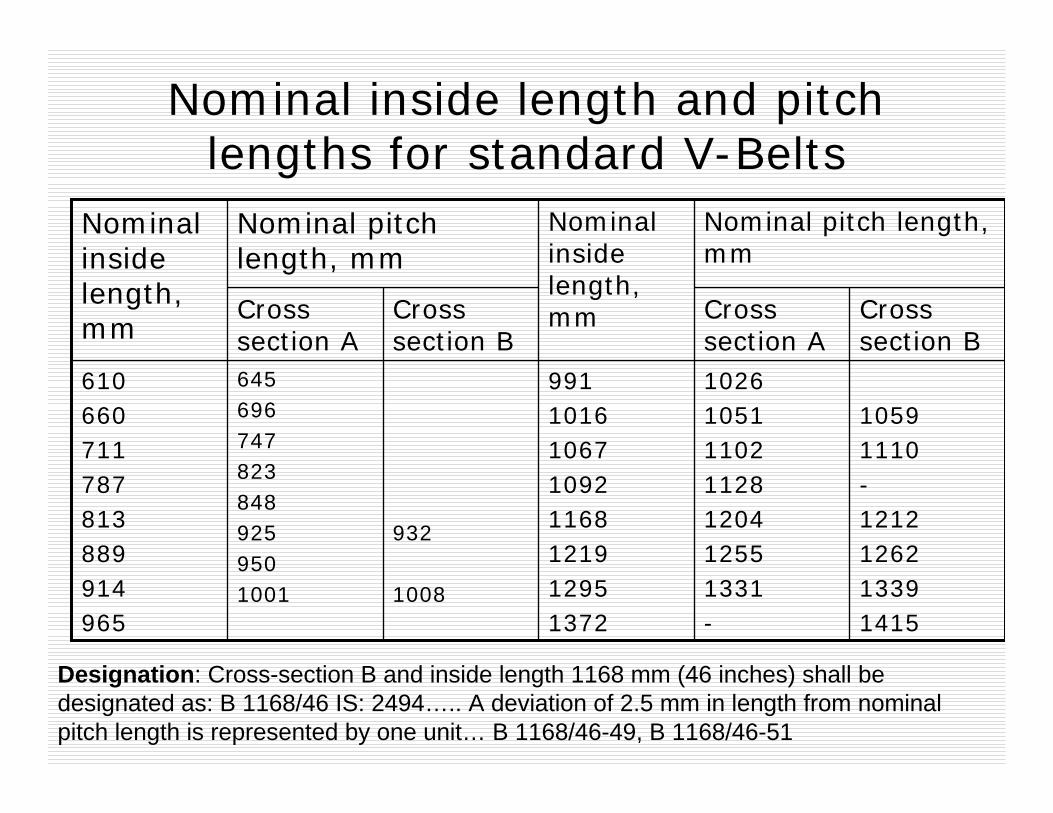
Nominal inside length and pitch lengths for standard V-Belts
10591110-1212126213391415
1026105111021128120412551331-
9911016106710921168121912951372
932
1008
6456967478238489259501001
610660711787813889914965
Cross section B
Cross section A
Cross section B
Cross section A
Nominal pitch length, mm
Nominal inside length, mm
Nominal pitch length, mm
Nominal inside length, mm
Designation: Cross-section B and inside length 1168 mm (46 inches) shall be designated as: B 1168/46 IS: 2494….. A deviation of 2.5 mm in length from nominal pitch length is represented by one unit… B 1168/46-49, B 1168/46-51

810141924
1216223238
60105150325540
.25-2.5
.75-3.751.25-9.08-18.515 and up
ABCDE
ht , mm
Wt , mm
Recommended min pulley pitch dia, mm
Drive load, kW
Cross section Symbol
Catalogue B
1144572, 4953, 5334, 6096, 6858, 7620, 8382E
843048, 3251, 3658, 4013, 4115, 4394, 4572D
741295, 1524, 1727, 1905, 2057, 2159, 2286, 2438, 2667, 2845, 3048, 3251, 3454, 3658
C
45889, 965, 1067, 1168, 1219, 1295, 1346, 1397, 1447, 1524, 1574, 1626, 1676, 1727
B
33660,787, 838, 889, 965, 1067, 1168, 1219, 1295, 1346, 1397, 1447, 1524, 1574, 1626
A
Quantity to be added to
get Pitch lengthNominal inside length, mmType

.16
.921.62.102.53.03.343.7
.941.52.02.52.93.23.53.75
1.251.702.02.42.73.03.23.4
1.21.51.71.952.12.32.52.6
.8
.951.01.21.31.41.51.5
105115125135145155165175+
B
2.34.05.56.57.58.3
1.43.34.75.96.87.58.0
2.03.54.55.46.06.67.0
1.983.03.64.24.75.05.4
1.41.92.22.52.72.93.0
150175200225250275305+
C
.28
.841.281.631.922.15
.11
.691.141.501.772.02.2
.4
.841.171.431.641.821.97
.46
.75
.981.161.301.401.51
.35
.50
.60
.69
.77
.83
.87
60758595105115125+
A252015105
Max Speed, m/sPitch dia, mm
Belt
Power rating, kW

Important points( ) ( )
( ) ( ) ( )⎪⎭
⎪⎬⎫
⎪⎩
⎪⎨⎧
−−⎥⎦⎤
⎢⎣⎡ −++⎥⎦
⎤⎢⎣⎡ +−=
−+++=
212
2
2121
212
21
222
25.0
422
DDLDDDDLC
CDDDDCL
PPd
ddP
ππ
π 1.5, 2, 2.25, 2.5, 3, 3.5, 4.0, 4.5, 5, 6,7, 7.5, 9, 10, 10.5, 11, 12, 13, 14, 15, 18
Pulley pitch dia., inch
απφαπφ
α
22
2sin
2
1
121
+=−=
⎟⎟⎠
⎞⎜⎜⎝
⎛ −= −
dCDD
Homework 7: Design a V-belt drive connecting 7.5 kW motor (rated speed 1440 rpm, shaft 1.5 inch) to a compressor. We need speed reduction = 3. Assume coefficient of friction = 0.25. Max center dist=500 mm.
( )12
2
3 DDCDC
d
d
+≤≥
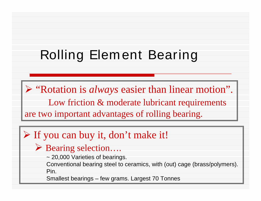
Rolling Element Bearing
“Rotation is always easier than linear motion”. Low friction & moderate lubricant requirements
are two important advantages of rolling bearing.
If you can buy it, don’t make it!Bearing selection….~ 20,000 Varieties of bearings. Conventional bearing steel to ceramics, with (out) cage (brass/polymers). Pin.Smallest bearings – few grams. Largest 70 Tonnes

Video Clips of
Rolling Element Bearings
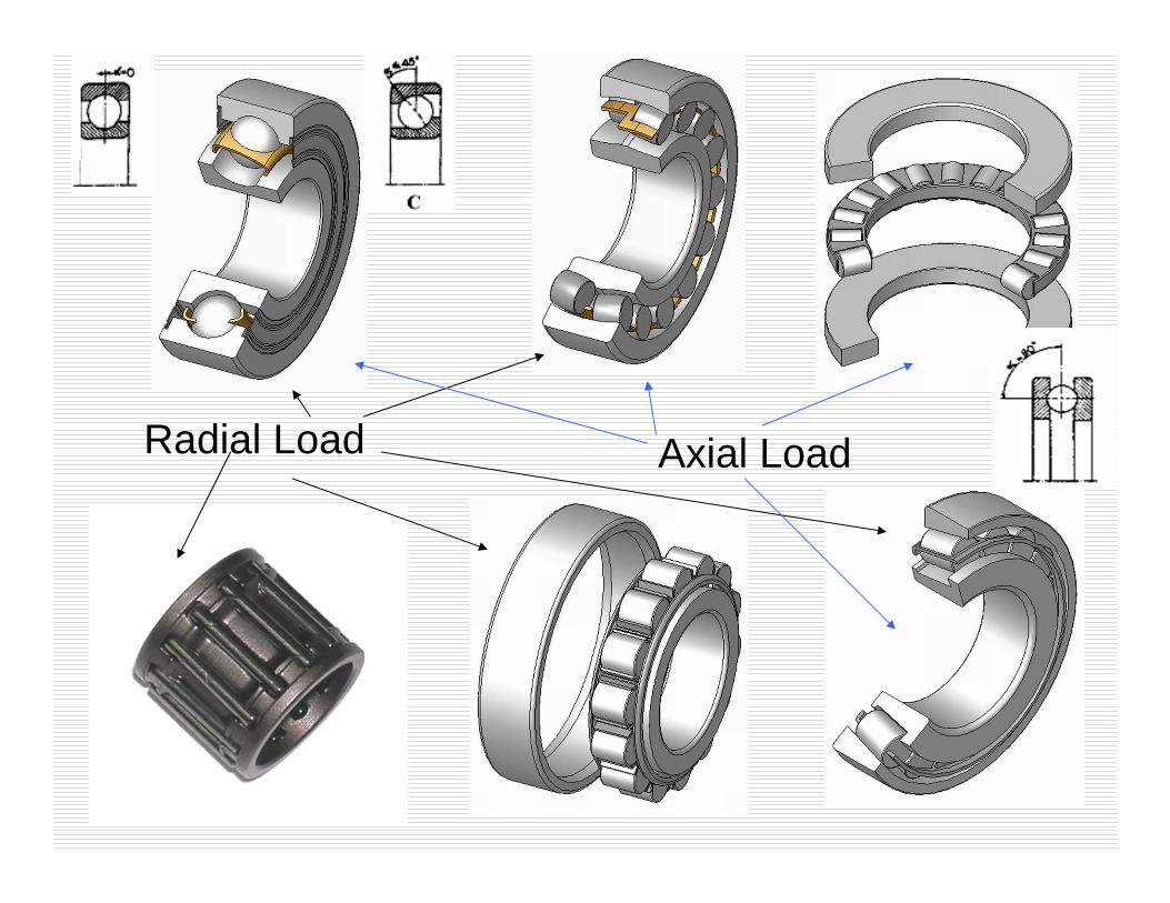
Radial Load Axial Load

Selection of bearing type
Cylindrical & Needle roller– Pure Radial LoadCylindrical roller thrust, ball thrust, four point angular contact ball bearings– Pure Axial loadTaper roller, spherical roller, angular contact bearings– Combined loadCylindrical roller, angular contact ball bearing–High speedDeep groove, angular contact, and cylindrical roller bearing– High running accuracy

In order of increasing outside bearing diameter
In increasing order
ACBBSABB
SRB
TRB DGBB
TBB
DGBB ACBB CRTB
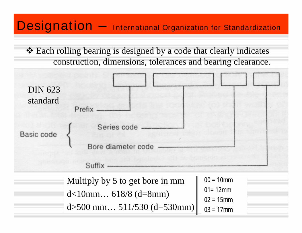
Designation – International Organization for Standardization
Multiply by 5 to get bore in mmd<10mm… 618/8 (d=8mm)d>500 mm… 511/530 (d=530mm)
00 = 10mm01= 12mm02 = 15mm03 = 17mm
Each rolling bearing is designed by a code that clearly indicates construction, dimensions, tolerances and bearing clearance.
DIN 623 standard

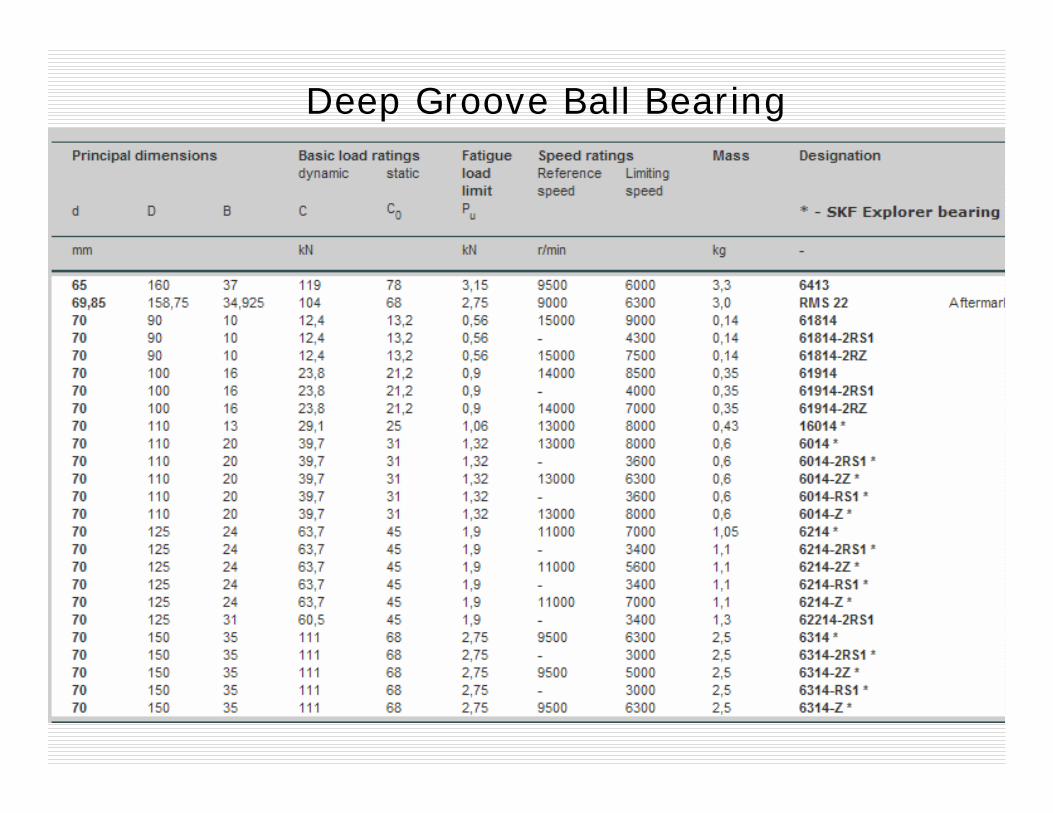
http://www.skf.com/portal/skf/home/products?newlink=first&lang=en
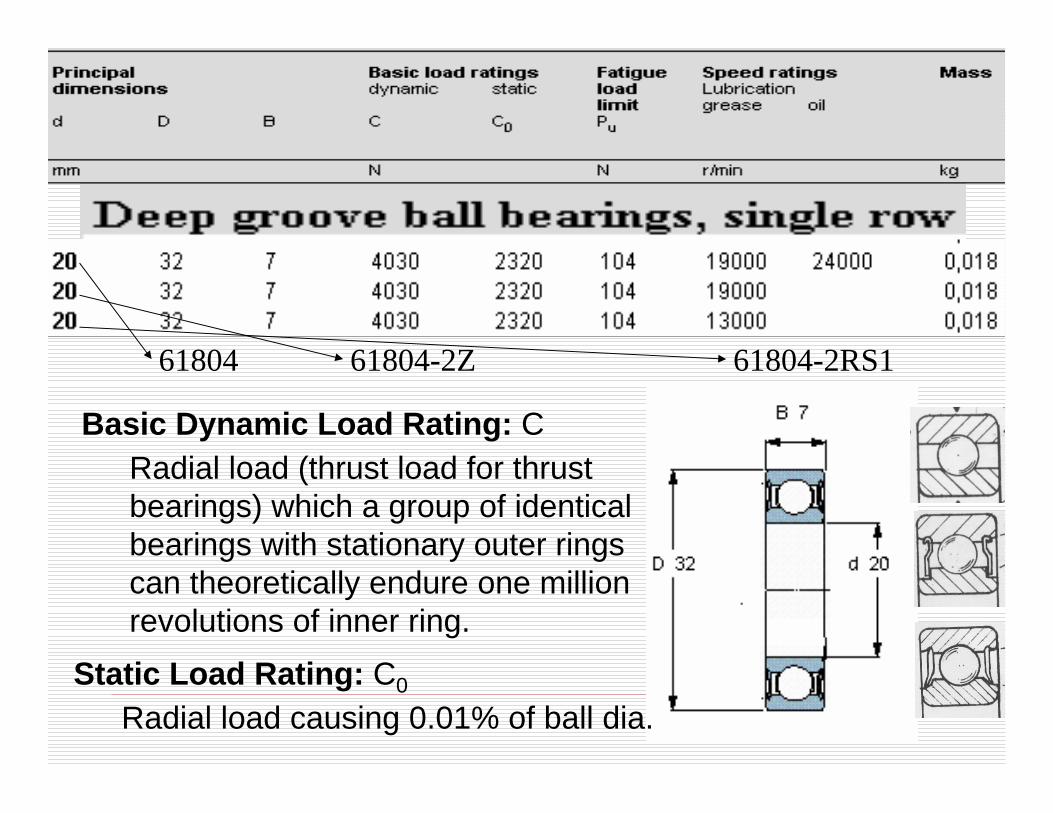
61804 61804-2Z 61804-2RS1
Basic Dynamic Load Rating: CRadial load (thrust load for thrust bearings) which a group of identical bearings with stationary outer rings can theoretically endure one million revolutions of inner ring.
Static Load Rating: C0
Radial load causing 0.01% of ball dia.
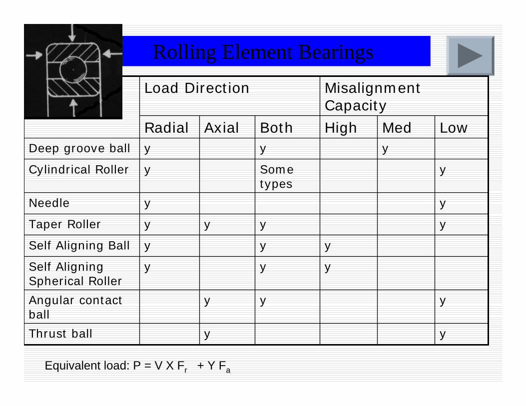
Rolling Element Bearings
yyThrust ball
yyyAngular contact ball
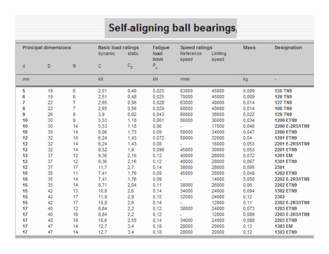
yyySelf Aligning Spherical Roller
yyySelf Aligning Ball
yyyyTaper Roller
yyNeedle
ySome types
yCylindrical Roller
yyyDeep groove ball
LowMedHighBothAxialRadial
Misalignment Capacity
Load Direction
Equivalent load: P = V X Fr + Y Fa
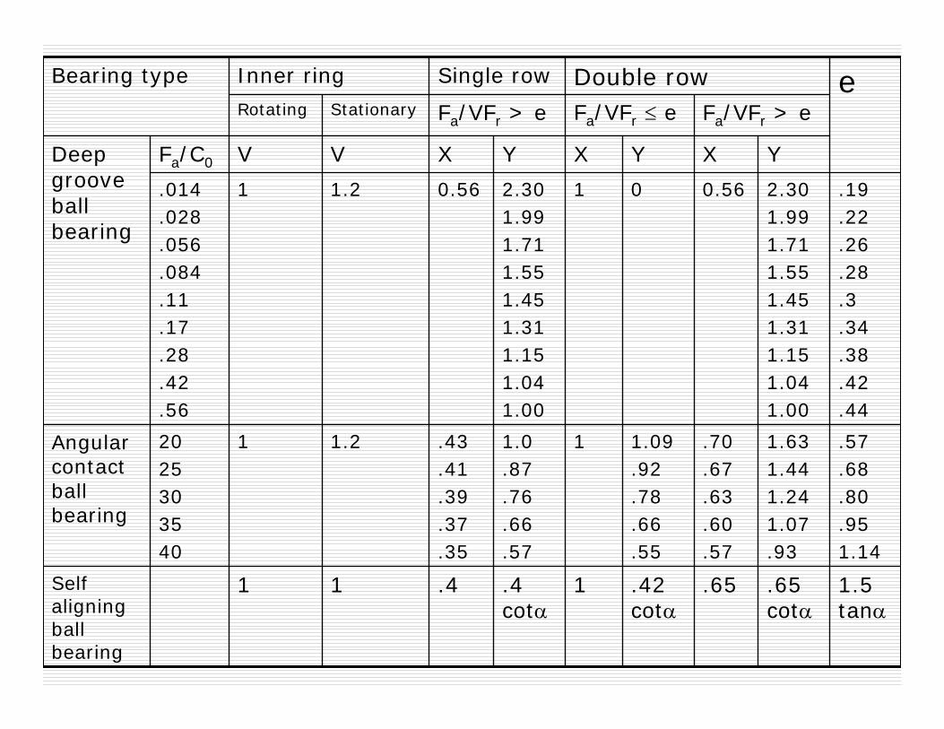
1.5 tanα
.65 cotα
.65.42 cotα
1.4 cotα
.411Self aligning ball bearing
.57
.68
.80
.951.14
1.631.441.241.07.93
.70
.67
.63
.60
.57
1.09.92.78.66.55
11.0.87.76.66.57
.43
.41
.39
.37
.35
1.212025303540
Angular contact ball bearing
.19
.22
.26
.28
.3
.34
.38
.42
.44
2.301.991.711.551.451.311.151.041.00
0.56012.301.991.711.551.451.311.151.041.00
0.561.21.014.028.056.084.11.17.28.42.56
YXYXYXVVFa/C0Deep groove ball bearing
Fa/VFr > eFa/VFr ≤ eFa/VFr > eStationaryRotatingeDouble rowSingle rowInner ringBearing type

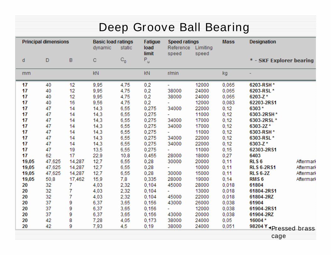
Deep Groove Ball Bearing
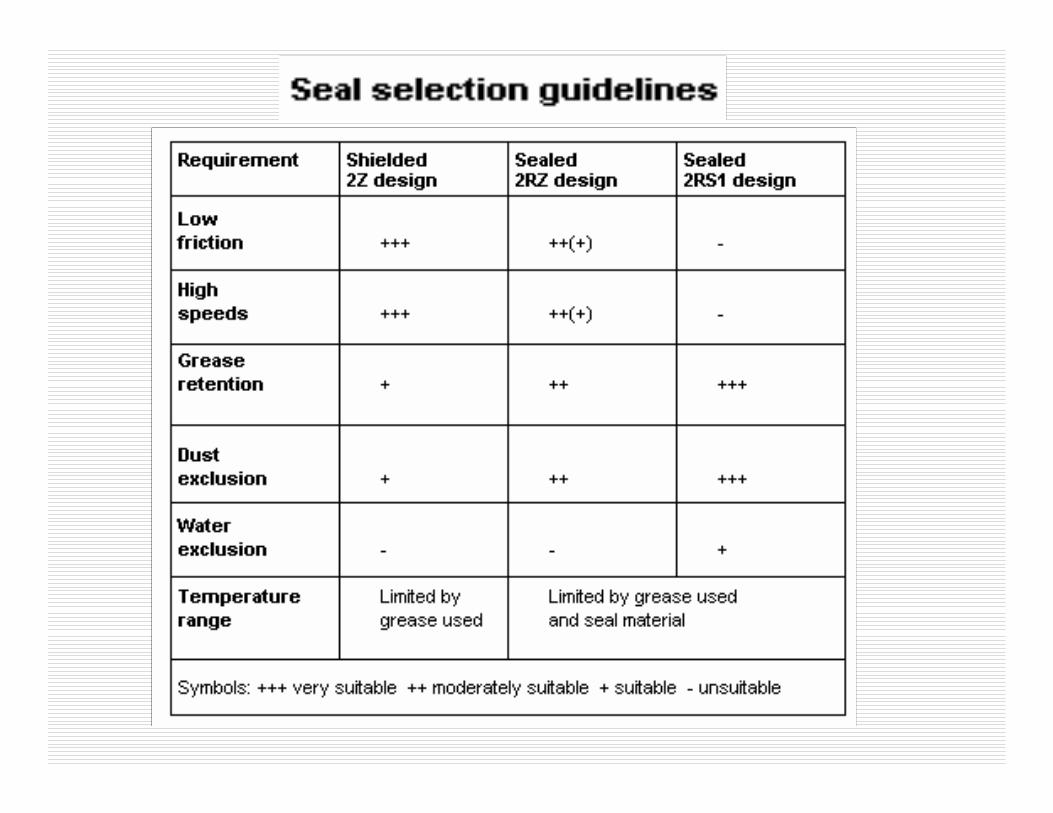
RSH Sheet steel reinforced contact seal of acrylonitrile-butadiene rubber (NBR) on one side of the bearing. L stand for low friction.

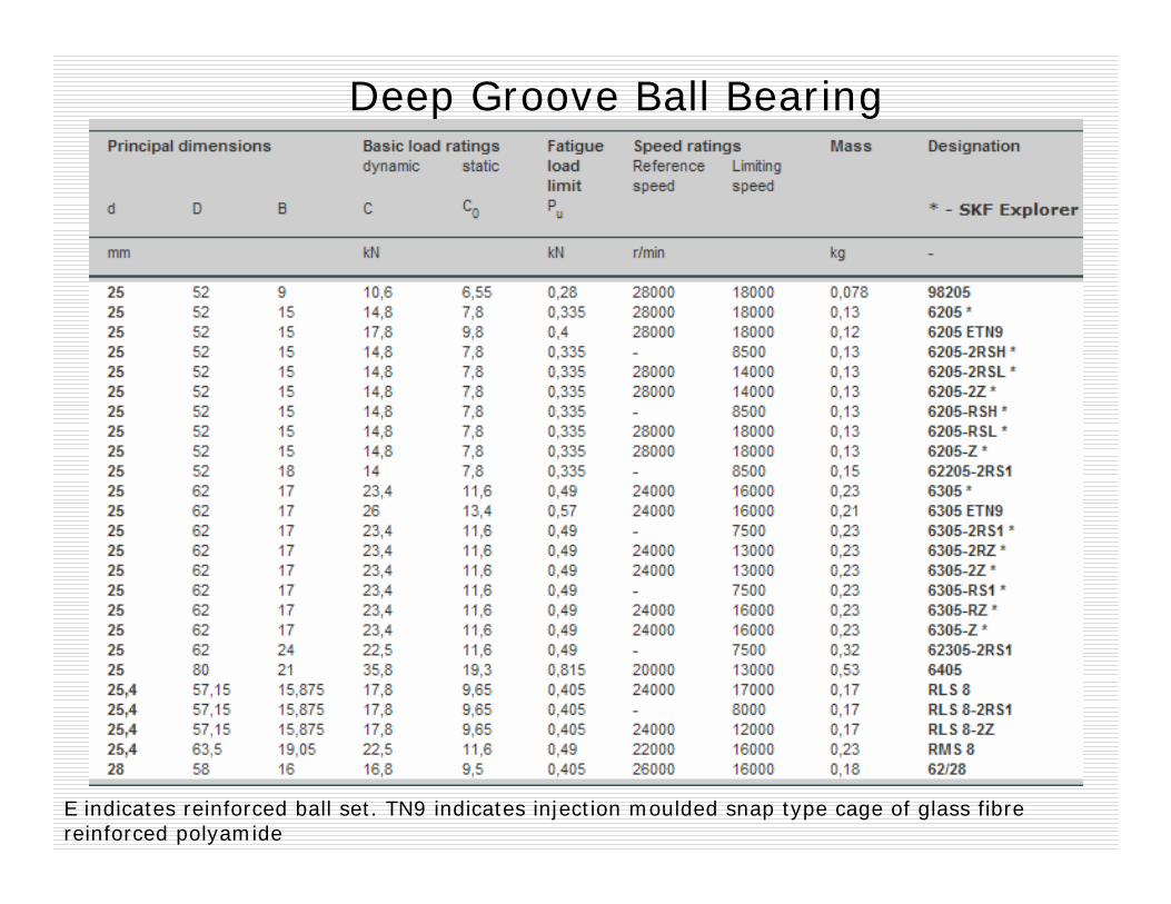
Deep Groove Ball Bearing
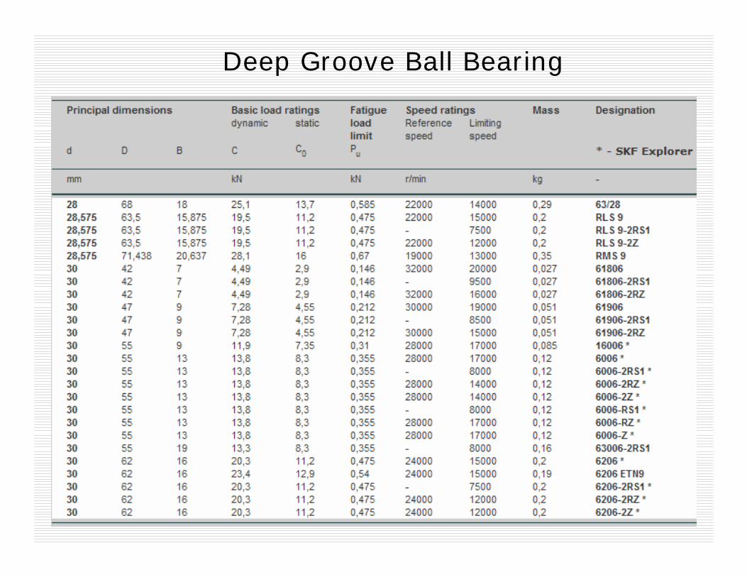
Deep Groove Ball Bearing
Pressed brass cage
Deep Groove Ball Bearing
E indicates reinforced ball set. TN9 indicates injection moulded snap type cage of glass fibrereinforced polyamide
Deep Groove Ball Bearing
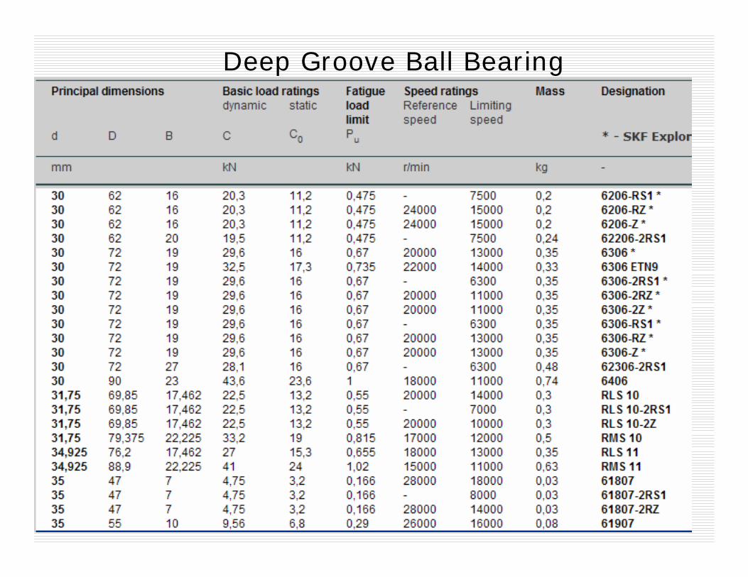
Deep Groove Ball Bearing
Deep Groove Ball Bearing


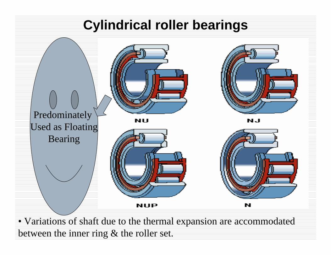
Cylindrical roller bearings
Predominately Used as Floating
Bearing
• Variations of shaft due to the thermal expansion are accommodated between the inner ring & the roller set.

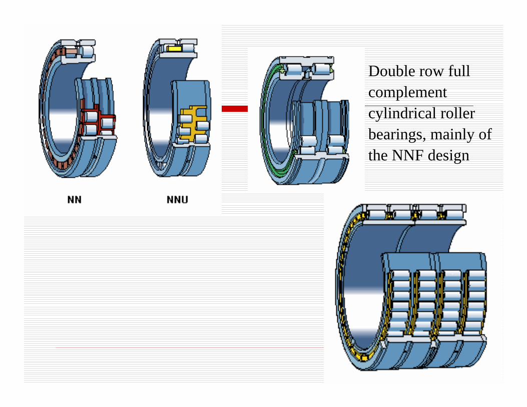
Double row full complement cylindrical roller bearings, mainly of the NNF design
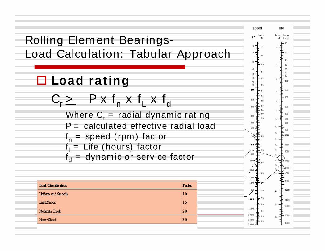
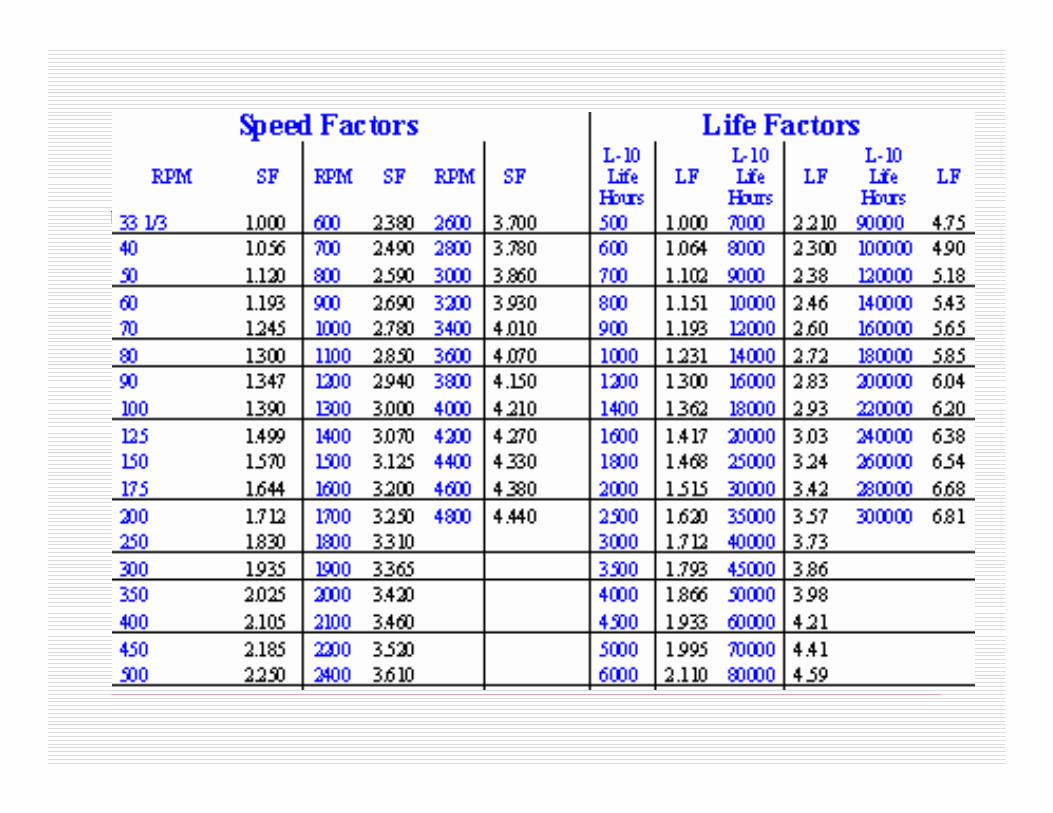
Rolling Element Bearings-Load Calculation: Tabular Approach
Load ratingCr > P x fn x fL x fd
Where Cr = radial dynamic rating P = calculated effective radial loadfn = speed (rpm) factorfl = Life (hours) factorfd = dynamic or service factor

Example 1: Radial load = 4448 N, Speed = 1000 rpm
Desired life= 30 000 hours, No Shock loading.
Cr > P x fn x fL x fdfd = 1.0; P = 4 448 N
fn= 2.78; fl= 3.42
=> Cr > 42, 290 N

Mathematical Approach
In ideal case, bearings fail by fatigue.
Dynamic load rating (catalogue C0 reading) is the load which 90% (reliability=0.9) of a group of identical bearings will sustain for minimum of 106 cycles.
( )
Speed60000,1000
PC
hoursin life Bearing
bearingsroller for 3
10bearings ballfor 3
10 3322116
a
aaaa
a
a
LPLPLPC
⎟⎟⎠
⎞⎜⎜⎝
⎛=⇒
=
=
===17.11
90
9.01log
1log
⎥⎥⎥
⎦
⎤
⎢⎢⎢
⎣
⎡
=e
eR R
LL
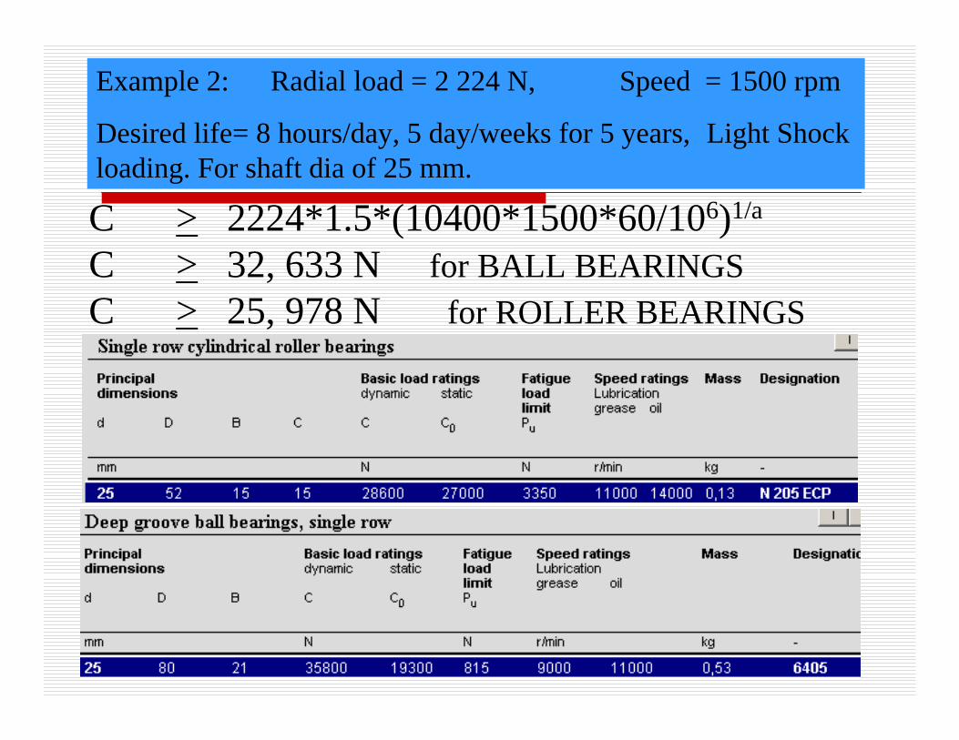
Example 2: Radial load = 2 224 N, Speed = 1500 rpm
Desired life= 8 hours/day, 5 day/weeks for 5 years, Light Shock loading. For shaft dia of 25 mm.
C > 2224*1.5*(10400*1500*60/106)1/a
C > 32, 633 N for BALL BEARINGSC > 25, 978 N for ROLLER BEARINGS
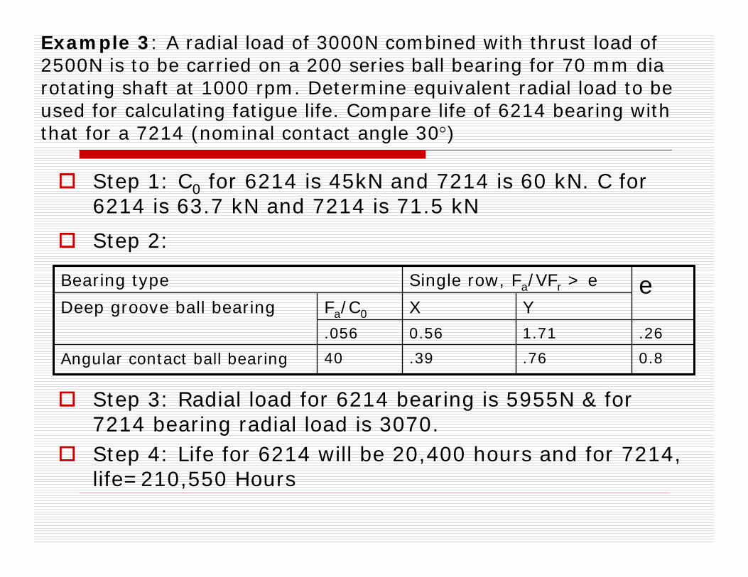
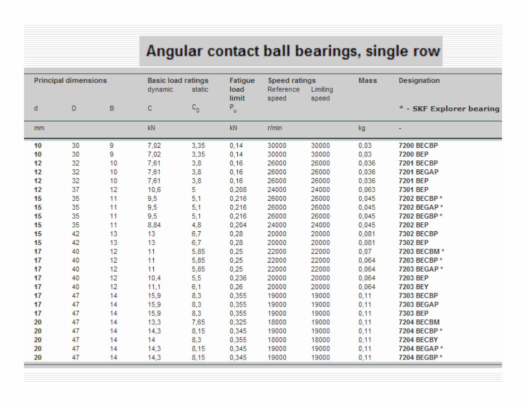
Example 3: A radial load of 3000N combined with thrust load of 2500N is to be carried on a 200 series ball bearing for 70 mm diarotating shaft at 1000 rpm. Determine equivalent radial load to be used for calculating fatigue life. Compare life of 6214 bearing with that for a 7214 (nominal contact angle 30°)
Step 1: C0 for 6214 is 45kN and 7214 is 60 kN. C for 6214 is 63.7 kN and 7214 is 71.5 kN
Step 2:
Step 3: Radial load for 6214 bearing is 5955N & for 7214 bearing radial load is 3070.Step 4: Life for 6214 will be 20,400 hours and for 7214, life=210,550 Hours
0.8.76.3940Angular contact ball bearing
.261.710.56.056
YXFa/C0Deep groove ball bearingeSingle row, Fa/VFr > eBearing type
Homework8: A single row cylindrical roller bearing N 205 ECP is subjected to pure radial load of 2800 N and rotational speed = 1500 rpm. Estimate the bearing life for reliability = 0.99.
ANS: 3448 Hours
Homework9: Select a suitable deep groove ball bearing for a shaft of 30 mm dia rotating at 2000 rpm. Bearing needs to bear a radial load of 2000 N and axial load of 400 N.
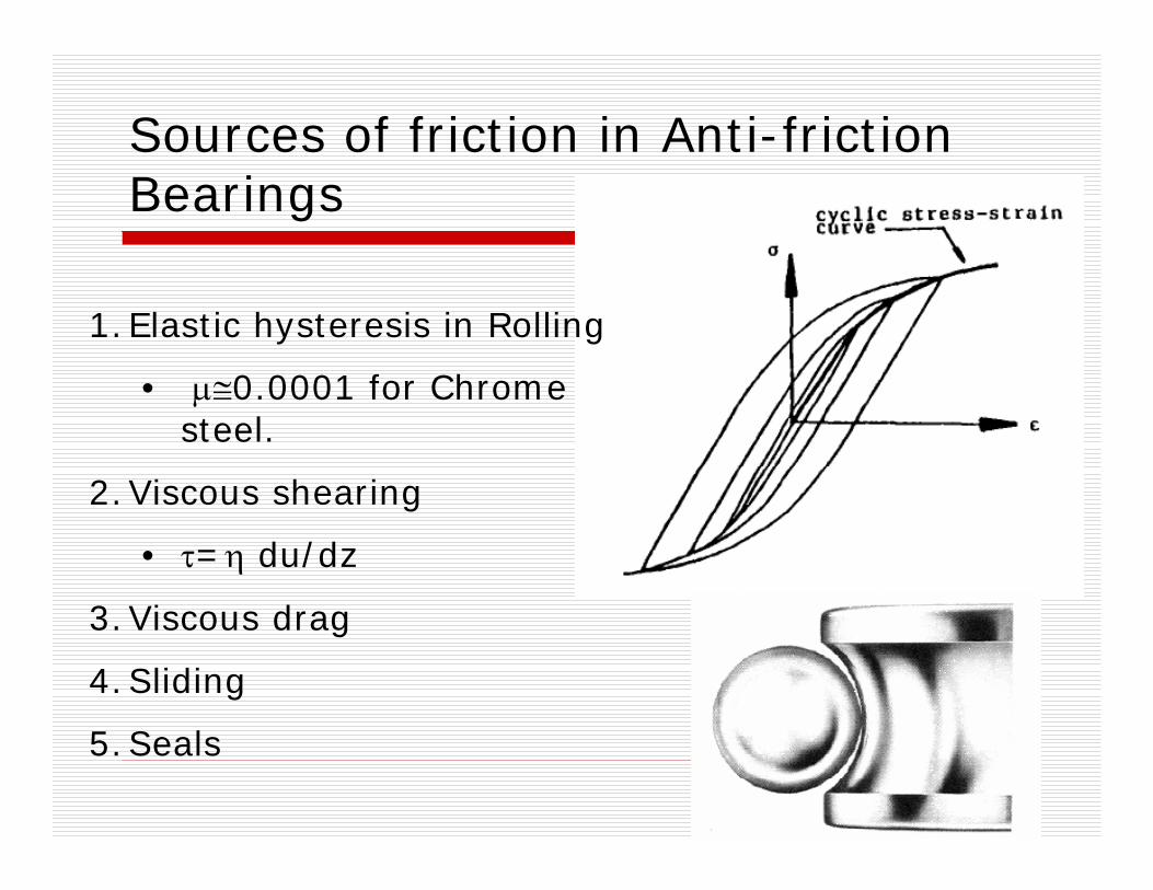
Sources of friction in Anti-friction Bearings
1.Elastic hysteresis in Rolling
• μ≅0.0001 for Chrome steel.
2.Viscous shearing
• τ=η du/dz
3.Viscous drag
4.Sliding
5.Seals

Friction Moments in Rolling Bearings
Load dependent
Lubricant and Speed dependent
Seal/Shield dependent
dia/2) Bore(PM P μ=
( )( ) 2000 56.1
2000 103
33/27
<−=
≥= −
NvifdfeM
NvifdNvfM
mLL
mLL
N.mm diaMax diaMin 2
12 ⎟⎟
⎠
⎞⎜⎜⎝
⎛ ++=
ffM s
Total friction moment M = MP+ML+MS
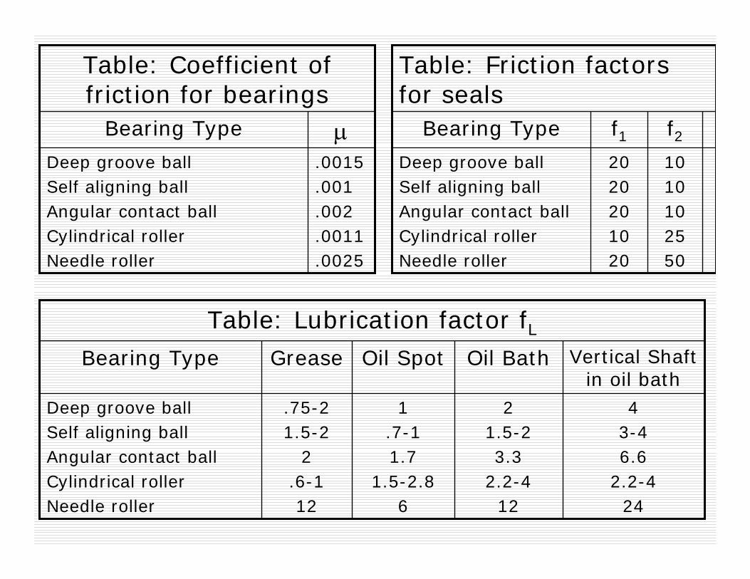
.0015
.001
.002
.0011
.0025
Deep groove ball Self aligning ballAngular contact ballCylindrical rollerNeedle roller
μBearing Type
Table: Coefficient of friction for bearings
Deep groove ball Self aligning ballAngular contact ballCylindrical rollerNeedle roller
Bearing Type
1.7-11.7
1.5-2.86
Oil Spot
.75-21.5-2
2.6-112
Grease
43-46.6
2.2-424
21.5-23.3
2.2-412
Vertical Shaft in oil bath
Oil Bath
Table: Lubrication factor fL
Deep groove ball Self aligning ballAngular contact ballCylindrical rollerNeedle roller
Bearing Type
1010102550
f22020201020
f1
Table: Friction factors for seals
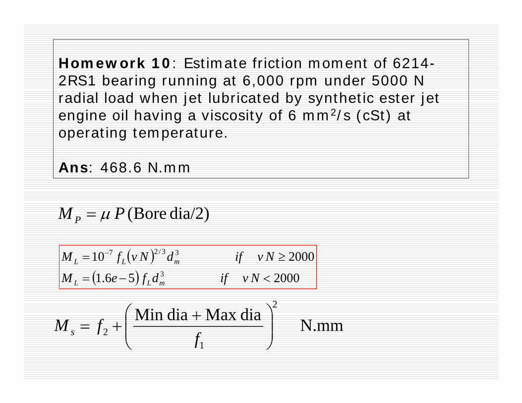
Homework 10: Estimate friction moment of 6214-2RS1 bearing running at 6,000 rpm under 5000 N radial load when jet lubricated by synthetic ester jet engine oil having a viscosity of 6 mm2/s (cSt) at operating temperature.
Ans: 468.6 N.mm
dia/2) Bore(PM P μ=
( )( ) 2000 56.1
2000 103
33/27
<−=
≥= −
NvifdfeM
NvifdNvfM
mLL
mLL
N.mm diaMax diaMin 2
12 ⎟⎟
⎠
⎞⎜⎜⎝
⎛ ++=
ffM s
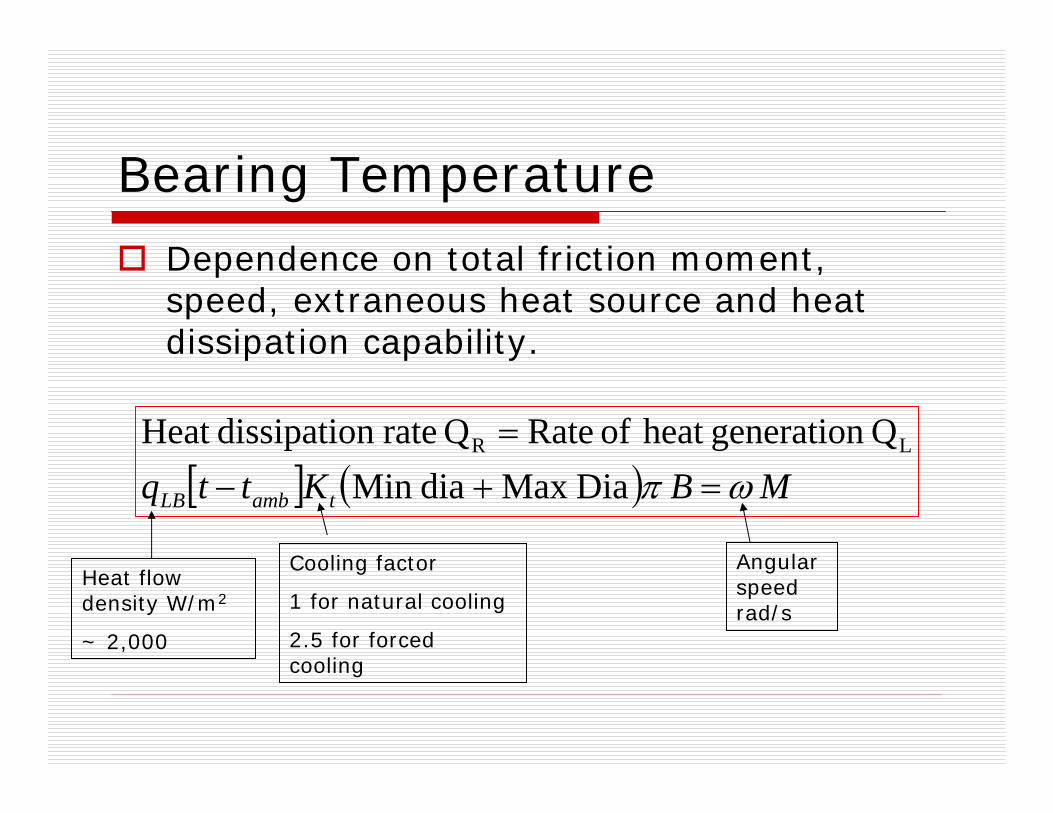
Bearing Temperature
Dependence on total friction moment, speed, extraneous heat source and heat dissipation capability.
[ ] ( ) MBKttq tambLB ωπ =+−=
DiaMax diaMin Q generationheat of RateQ raten dissipatioHeat LR
Heat flow density W/m2
~ 2,000
Cooling factor
1 for natural cooling
2.5 for forced cooling
Angular speed rad/s
Homework 11: Estimate bearing operating temperature of 6214-2RS1 bearing running at 6,000 rpm under 5000 N radial load when jet lubricated by synthetic ester jet engine oil having a viscosity of 6 mm2/s (cSt) at operating temperature. Assume ambient temp = 30°C and forced cooling of bearing.
Ans: 34°C
Bearing Mounting Interference fit
One part slightly interferes with space that the other part is taking up.Fastening between two parts (i.e. shaft into bearing, bearing into housing) aiming that even large amount of torque cannot turn one of them relative to other.Shaping (i.e. turning, drilling, boring, reaming, grinding, etc.) shaft/housing with slight deviation in size from nominal dimensions. Slightly oversized shaft, slightly undersized housing. Press/shrink fitting of inner race on shaft causes expansion of inner ring. Similarly press fitting of outer ring in housing causes former member to shrink slightly.

Preload ????If interference fits exceed the internal radial clearance, the rolling elements become preloaded.
Clearance before installation & after installation ???
Hot rolling, Flame cutting
Sand Casting
Forging
Die Casting
Drilling
Cold Rolling, Drawing
Extruding
Planing, Shaping
Milling
Sawing
Boring, Turning
Reaming
Broaching
Plan grinding
Diamond turning
Cylindrical grinding
Super finishing
Honing
Lapping
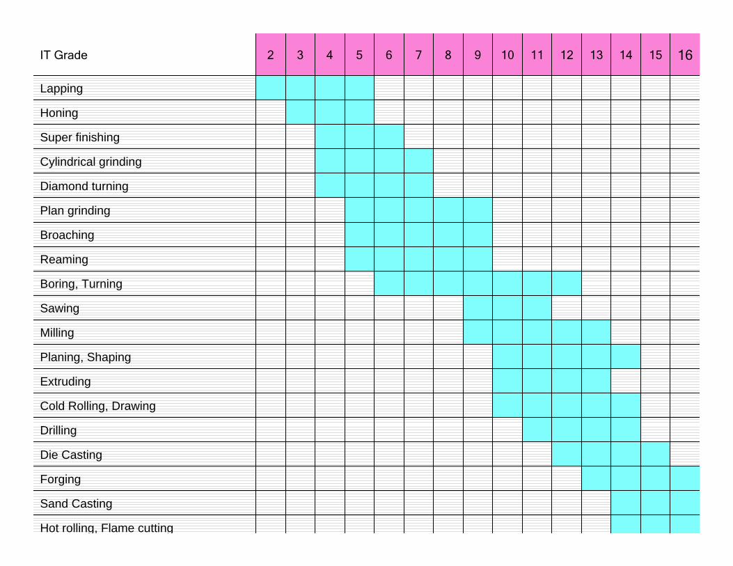
1615141312111098765432IT Grade
13001150100087074062052043036030025014
81072063054046039033027022018014013
52046040035030025021018015012010012
32029025022019016013011090756011
210185160140120100847058484010
13011510087746252433630259
81726354463933272218148
52464035302521181512107
32292522191613119866
232018151311986545
1614121087654434
12108654432.52.523
875432.52.521.51.51.22
64.53.52.521.51.51.2110.81
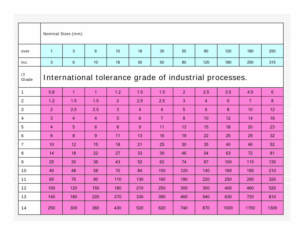
International tolerance grade of industrial processes. IT Grade
315250180120805030181063inc.
2501801208050301810631over
Nominal Sizes (mm)

Tolerances:Allowable
0 μm< IF< 12 μmLoose Preloading
Achievable
Boring, Turning
Plan grinding
Diamond turning
Cylindrical grinding
Super finishing
Honing
Lapping
1615141312111098765432IT Grade
Example: We need to choose 03/04 bearing.

52043014
33027013
21018012
13011011
847010
52439
33278
21187
13116
985
654
433
2.522
1.51.21
IT Grade
3018inc.
1810over
Nominal Sizes (mm)
Super finishing
Honing
Lapping
65432IT Grade
0.1° misalignment results 52 μm preloading for 30 mm length
0.01° misalignment results 5 μm preloading.
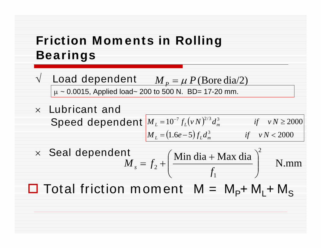
Friction Moments in Rolling Bearings
√ Load dependent
× Lubricant and Speed dependent
× Seal dependent
dia/2) Bore(PM P μ=
( )( ) 2000 56.1
2000 103
33/27
<−=
≥= −
NvifdfeM
NvifdNvfM
mLL
mLL
N.mm diaMax diaMin 2
12 ⎟⎟
⎠
⎞⎜⎜⎝
⎛ ++=
ffM s
Total friction moment M = MP+ML+MS
μ ~ 0.0015, Applied load~ 200 to 500 N. BD= 17-20 mm.

( )
NWW
W
819)5.1^4/(6550 WPreload
655010100*4.
2
32
2
32
32
2
32
1
2
1
==
=→=δδ
10 micron interference causes 819 N preload.
15 microns --- 1500 N preload.
20 microns -- 2316 N load
Static Load Rating: C0.. Radial load causing 0.01% of ball dia 0.4 μm plastic deformation results if 6550 N load is applied on the bearing.
Homework 12: Estimate bearing operating temperature of 6214-2RS1 bearing running at 6,000 rpm under 1000 N radial load when jet lubricated by synthetic ester jet engine oil having a viscosity of 6 mm2/s (cSt) at operating temperature. Assume ambient temp = 30°C, ball dia=6 mm, preloading of bearing = 10 microns, and forced cooling of bearing.Ans: 33.6 °C

Failure of Four Row Cylindrical Roller Bearing
Two large roller bearings – (ID = 865 mm, OD = 1180 mm) failed in a cold rolling mill.
one bearing failed within 105 hours (installed on 05/01/03 and failed completely on 10/01/03), and
other failed within 300 hours of operation (installed on 05/01/03 and removed on 24/01/03 due to detection of excessive vibration and metal particles).
Expected life of bearings was approximately 40,000 operating hours
Survival rate 0.5% and 1.0%.

Failed Bearing

Bearing subjected to normal load
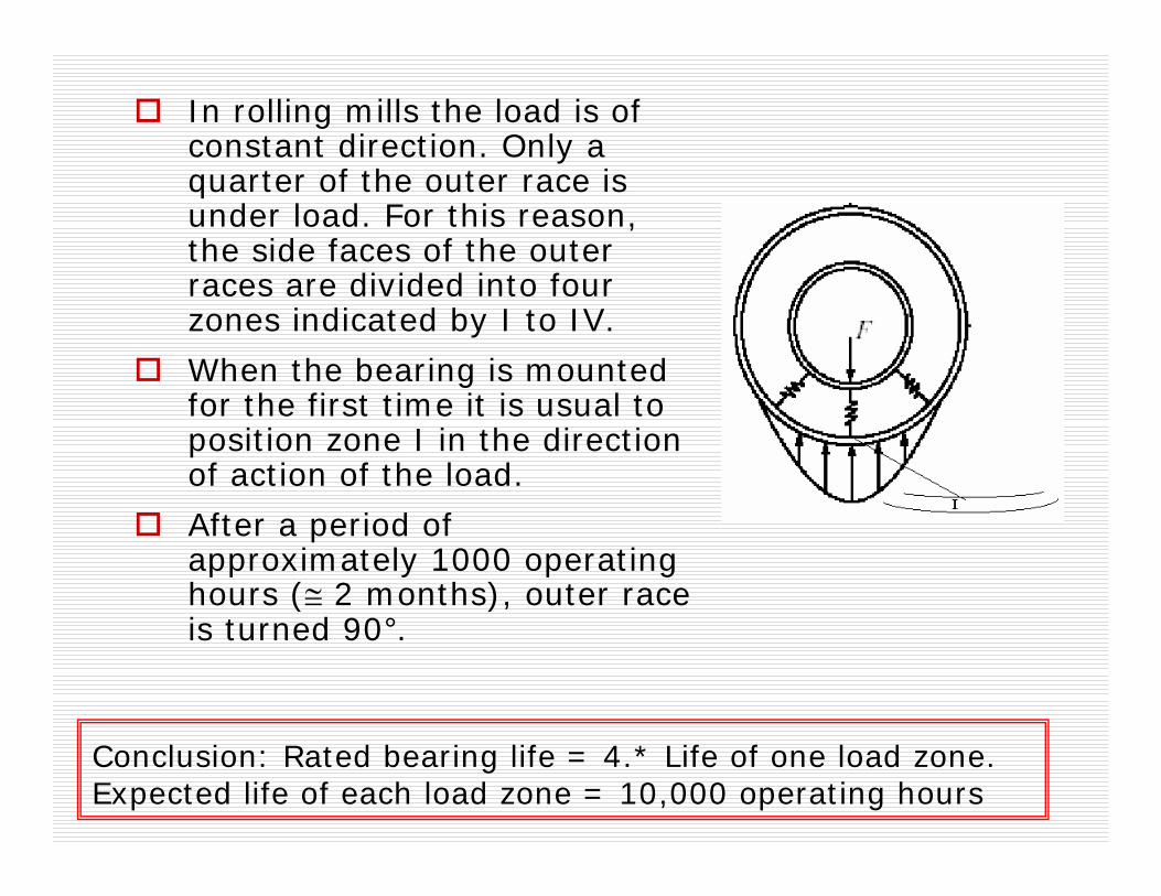
In rolling mills the load is of constant direction. Only a quarter of the outer race is under load. For this reason, the side faces of the outer races are divided into four zones indicated by I to IV.
When the bearing is mounted for the first time it is usual to position zone I in the direction of action of the load.
After a period of approximately 1000 operating hours (≅ 2 months), outer race is turned 90°.
Conclusion: Rated bearing life = 4.* Life of one load zone. Expected life of each load zone = 10,000 operating hours

Detailed survey of failed bearing indicated placement of hole on the line of maximum load.
Four holes of 3/8” 10 UNC 3B of 45mm depth were drilled and tapped to facilitate the handling of outer race.
Hole
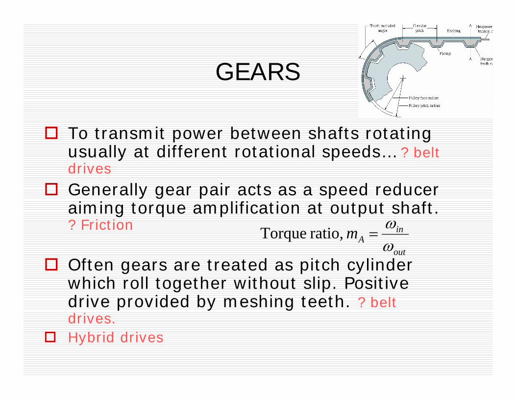
GEARS
To transmit power between shafts rotating usually at different rotational speeds… ? belt drives
Generally gear pair acts as a speed reducer aiming torque amplification at output shaft. ? Friction
Often gears are treated as pitch cylinder which roll together without slip. Positive drive provided by meshing teeth. ? belt drives.Hybrid drives
out
inAm
ωω
= ratio, Torque
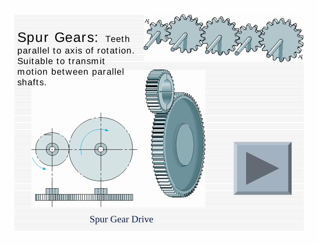
Spur Gear Drive
Spur Gears: Teeth parallel to axis of rotation. Suitable to transmit motion between parallel shafts.
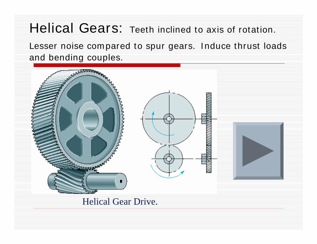
Helical Gears: Teeth inclined to axis of rotation.
Lesser noise compared to spur gears. Induce thrust loads and bending couples.
Helical Gear Drive.
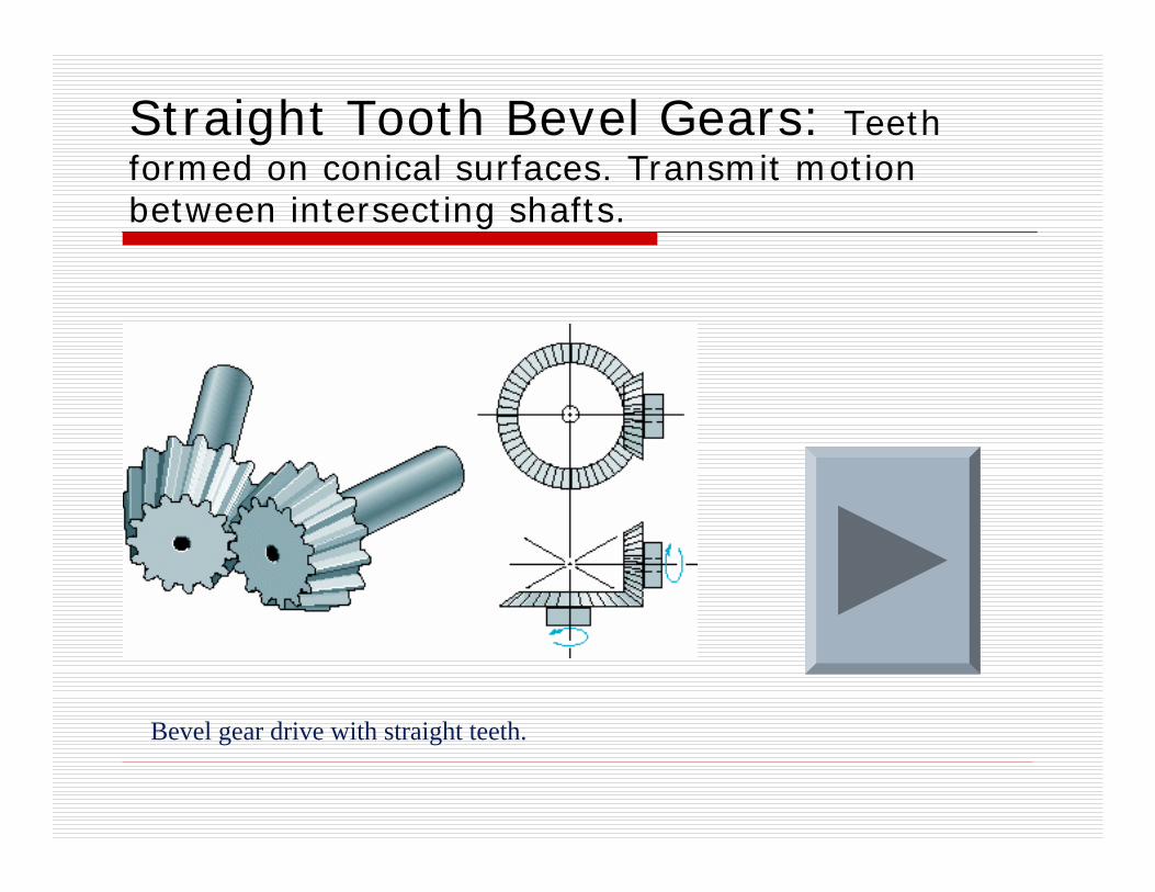
Straight Tooth Bevel Gears: Teeth formed on conical surfaces. Transmit motion between intersecting shafts.
Bevel gear drive with straight teeth.

Worm Gears: Worm resembles a screw. Direction of rotation of worm wheel??? High speed ratio.
Worm Gear Drive. (a) Cylindrical teeth; (b) double enveloping.
Spur Gear Nomenclature
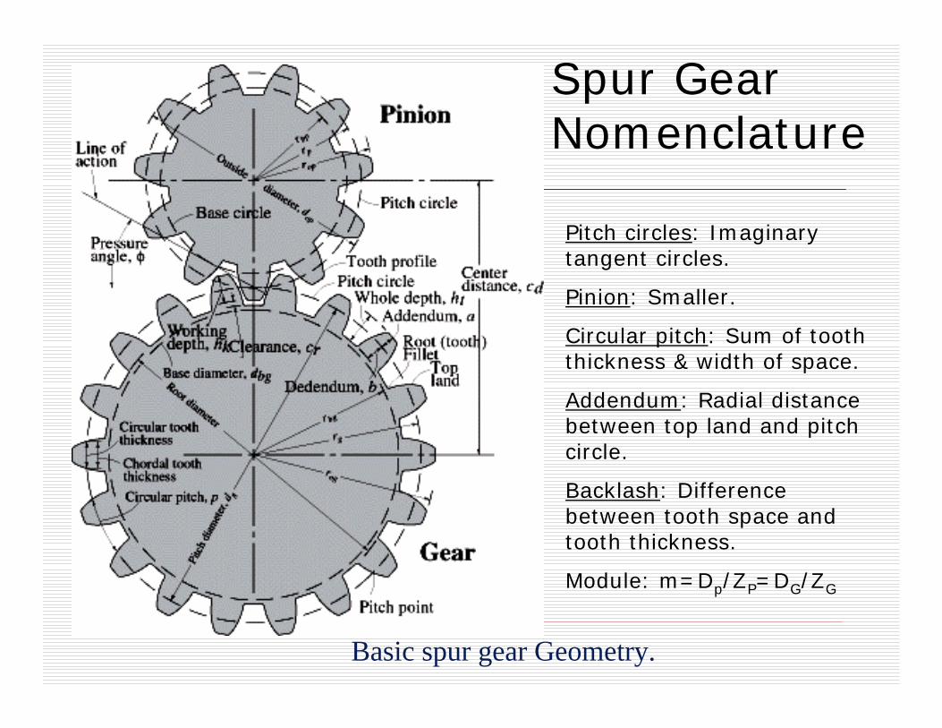
Basic spur gear Geometry.
Pitch circles: Imaginary tangent circles.
Pinion: Smaller.
Circular pitch: Sum of tooth thickness & width of space.
Addendum: Radial distance between top land and pitch circle.
Backlash: Difference between tooth space and tooth thickness.
Module: m=Dp/ZP=DG/ZG
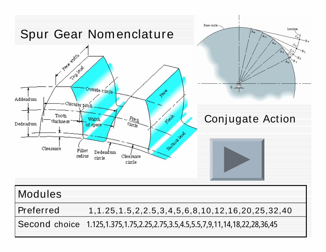
Spur Gear Nomenclature
Second choice 1.125,1.375,1.75,2.25,2.75,3.5,4.5,5.5,7,9,11,14,18,22,28,36,45Preferred 1,1.25,1.5,2,2.5,3,4,5,6,8,10,12,16,20,25,32,40
Modules
Conjugate Action

Catalogue B
All sizes shown above are in 20o PA =Presure Angle (Note: 14.1/2o PA is also supplied)
152.6027 or 14.75HBIGM04.75
142.8027 or 14.5HBIGM04.5
147.0027 or 14.25HBIGM04.25
1358.005050HBIGM20124.6027 or 14HBIGM04
1190.005018HBIGM18123.2027 or 13.75HBIGM03.75
980.004016HBIGM16120.4027 or 13.5HBIGM03.5
665.004014HBIGM14123.2027 or 13.25HBIGM3.25
616.004012HBIGM12119.0027 or 13HBIGM03
560.004011HBIGM11110.6027 or 12.75HBIGM02.75
512.403210HBIGM10107.8027 or 12.5HBIGM02.5
456.40329HBIGM09103.6027 or 12.25HBIGM02.25
392.0032 or 1-1/48HBIGM08103.6027 or 12HBIGM02
329.0032 or 1-1/47HBIGM07100.8027 or 11.75HBIGM01.75
193.2027 or 16HBIGM0698.0027 or 11.5HBIGM01.5
172.2027 or 15.5HBIGM05.595.2027 or 11.25HBIGM01.25
155.4027 or 15HBIGM0595.2027mm or 1”1mmHBIGM01
PoundsBore
diameter of cutter
Module MMPounds
Bore diameter of cutter
Module MM

214 - 167317 - 206421 - 255526 - 344635 - 543755 - 13428135 - RACK1
(European Cutter No)Cuts TeethBSS Cutter
Number
Catalogue B

Pitch and Base Circles.? Cross belt
1m.8m20Stub
1.25m1.35m
1m25
1.25m1.35m
1m22.5
1.25m1.35m
1m20Full depth
Dedendum
Addendum
φ, deg
Tooth system
c

Contact Ratio
)Zr
(2
recess ofLength approach ofLength Base_pitch
action ofLength
g
bgπ
+

Contact Ratio
g
bgogbpop
bgogbpop
bgog
bpop
bpop
ZCrrrr
rrrr
rr
rr
caba
rrb
/r2sin
ratioContact
sin)rr( ab action, ofLength
sinracSimilarly
sinrcb or,
cbLength
aLength
sinr caLength
bg
2222
gp2222
g22
p22
**
22*
p*
πφ
φ
φ
φ
φ
−−+−=
+−−+−=
−−=
−−=
−=
−=
=
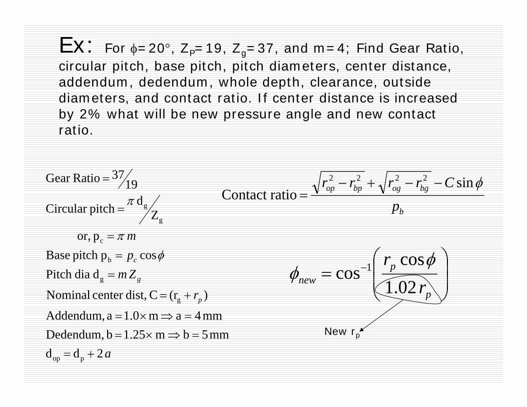
Ex: For φ=20°, ZP=19, Zg=37, and m=4; Find Gear Ratio, circular pitch, base pitch, pitch diameters, center distance, addendum, dedendum, whole depth, clearance, outside diameters, and contact ratio. If center distance is increased by 2% what will be new pressure angle and new contact ratio.
a
r
Zmpm
p
g
c
2d dmm5bm 1.25 b Dedendum,
mm4a m1.0 a Addendum,
)(r C dist,center Nominal
d diaPitch cosppitch Base
p or,
Zd pitch Circular
1937 RatioGear
pop
g
g
b
c
g
g
+==⇒×=
=⇒×=
+=
==
=
=
=
φπ
πb
bgogbpop
pCrrrr φsin
ratioContact 2222 −−+−
=
⎟⎟⎠
⎞⎜⎜⎝
⎛= −
p
pnew r
r02.1cos
cos 1 φφ
New rp

Design of Spur Gears
Breakage of gear teethExcessive wear of gear tooth surfaceExcessive noise Excessive heat
Patent U.S. 5,503,045
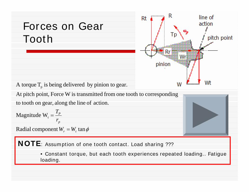
Forces on Gear Tooth
φtancomponent Radial
WMagnitude
action. of line thealong gear,on tooth toingcorrespond tooth toone from ed transmittis W Force point,pitch At
gear. pinion toby delivered being is T A torque
t
p
tr
p
P
WW
rT
=
=
NOTE: Assumption of one tooth contact. Load sharing ???
• Constant torque, but each tooth experiences repeated loading.. Fatigue loading.

Ex: Pinion shaft passes 15kW at 2500 rpm. For φ=25°, ZP=14, m=4, and Gear Ratio=3.5, determine transmitted loads on gear teeth. Find pitch diameters, mean and alternative components of transmitted load.
( )
2
2
954tan,
20462//,
56144
.55.2003.575.3
3.57)60/25002/(15000
49145.3
t
t
tr
ppt
pp
g
p
g
WloadeAlternativ
WloadMean
NWWloadRadial
NdTWloadTangential
mmZmd
mNT
T
Z
=
=
==
===
=×==
=×=
==
=×=
φ
π

Homework 13: What will the pressure angle be if the center distance of a 20° pressure angle gear pair is increased by 7%.
Homework 14: Find out the mean and alternating load components of a gear-set that transmits 50 kW at 1600 pinion rpm. φ=25°, ZP=23, Zg=57, and m=4.
Stresses in Spur Gears
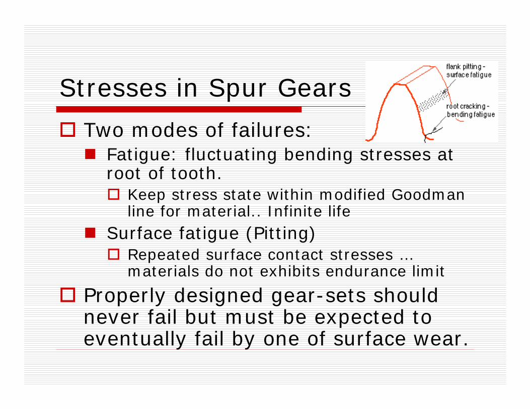
Two modes of failures:Fatigue: fluctuating bending stresses at root of tooth.
Keep stress state within modified Goodman line for material.. Infinite life
Surface fatigue (Pitting)Repeated surface contact stresses …materials do not exhibits endurance limit
Properly designed gear-sets should never fail but must be expected to eventually fail by one of surface wear.

Bending Stresses
AssumptionsCompression due to radial component of force is negligible.Teeth do not share loadGreatest force is exerted at tip
Lewis Eq.
6/2tFlW
ModulusSectionMoment
tb
b
=
=
σ
σ
mYFWt
b =σ
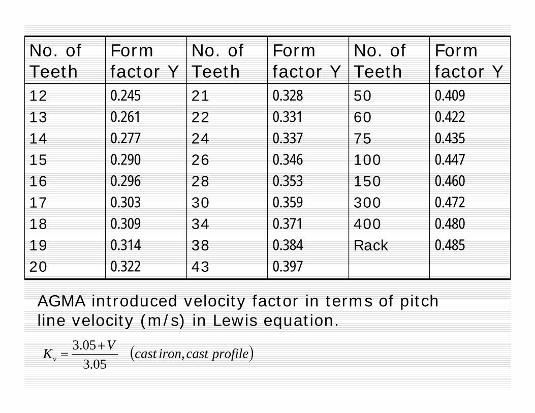
212224262830343843
No. of Teeth
0.2450.2610.2770.2900.2960.3030.3090.3140.322
Form factor Y
0.4090.4220.4350.4470.4600.4720.4800.485
506075100150300400Rack
0.3280.3310.3370.3460.3530.3590.3710.3840.397
121314151617181920
Form factor Y
No. of Teeth
Form factor Y
No. of Teeth
AGMA introduced velocity factor in terms of pitch line velocity (m/s) in Lewis equation.
( )profilecastironcastVKv ,05.3
05.3 +=
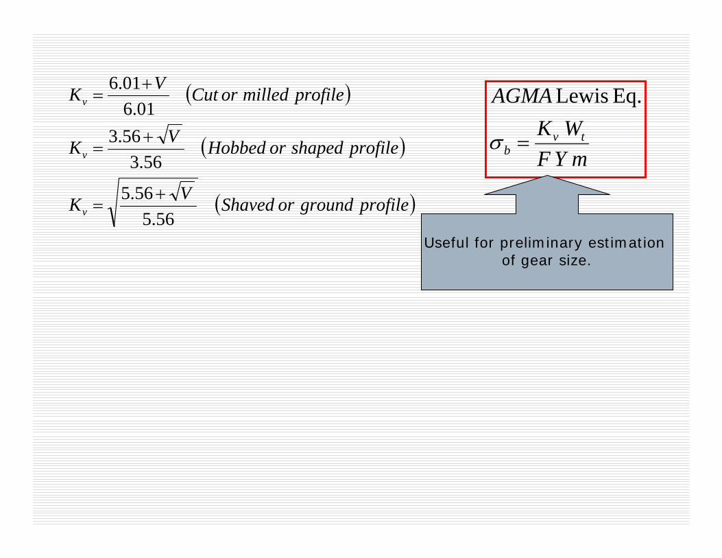
( )
( )
( )profilegroundorShavedVK
profileshapedorHobbedVK
profilemilledorCutVK
v
v
v
56.556.5
56.356.3
01.601.6
+=
+=
+=
mYFWK
AGMA
tvb =σ
Eq. Lewis
Useful for preliminary estimation of gear size.
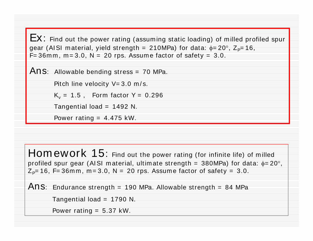
Homework 15: Find out the power rating (for infinite life) of milled profiled spur gear (AISI material, ultimate strength = 380MPa) for data: φ=20°, ZP=16, F=36mm, m=3.0, N = 20 rps. Assume factor of safety = 3.0.
Ans: Endurance strength = 190 MPa. Allowable strength = 84 MPa
Tangential load = 1790 N.
Power rating = 5.37 kW.
Ex: Find out the power rating (assuming static loading) of milled profiled spur gear (AISI material, yield strength = 210MPa) for data: φ=20°, ZP=16, F=36mm, m=3.0, N = 20 rps. Assume factor of safety = 3.0.
Ans: Allowable bending stress = 70 MPa.
Pitch line velocity V=3.0 m/s.
Kv = 1.5 , Form factor Y = 0.296
Tangential load = 1492 N.
Power rating = 4.475 kW.

Driven Machines
Power Source Uniform Light shock Moderate shock Heavy shock Application factor, Ka Uniform (Electric motor, turbine) Light shock (Multicylinder) Moderate shock
1.00
1.20
1.30
1.25
1.40
1.70
1.50
1.75
2.00
1.75 2.25 2.75
AGMA Bending Stress Equation
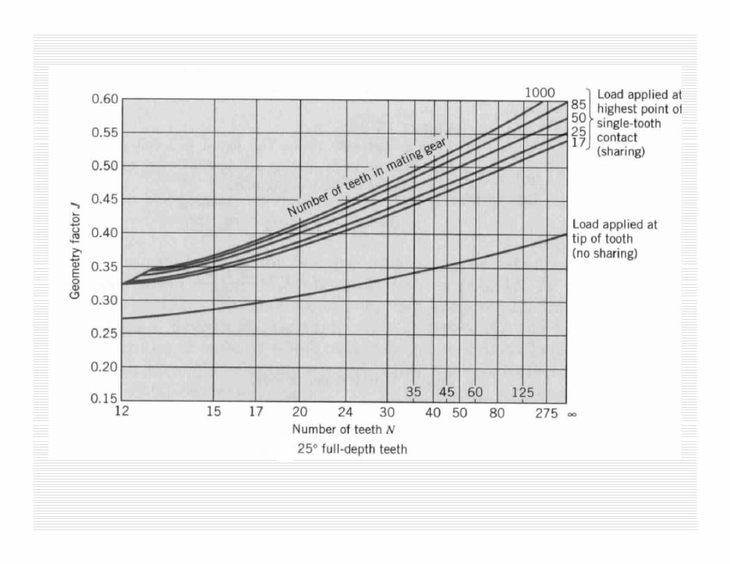
loading ofpoint angle, pressureon depends FactorGeometrybendingAGMAJ
KKKJmF
WKmBa
tvb
=
=σ
1.61.71.82.0
< 50150250>500
KmFace width, mm
Load distribution factor Km
t
RBBB
BB
htmwheremK
mK
=≥=
<≤+−=
2.1 0.1
2.1m0.5 4.32factor thicknessRim B


Ex: A gear pair (ZP=23, φ=20°, Zg =24, m=1.75, F=10.0 mm) transmits 8 N.m torque from crankshaft (rotational speed 8000 rpm) of single cylinder IC engine to wheels. Bore diameter of pinion is 17 mm, and bore dia of gear is 20 mm. Using AGMA bending stress formula to determine the maximum bending stress. Assume gears are grounded.
( )
( )12.1
4375.95.09375.375.1*25.2
635.37
875.3575.1*25.1*2
3185.156.5
56.5 0.42
/86.1660
800025.40 25.40
6.1 0.2
=⇒>
=−===
=
=−=
=+
==
→==
==
BB
pprootR
t
groot
pproot
vg
p
ma
Km
Boredtmmh
d
dd
VKd
smVd
KKπ
MPa
KKKJmF
WK
b
mBatv
b
6.368=⇒
=
σ
σ

Allowable Bending Stress vs. Brinell Hardness
Effect of Brinell hardness on allowable bending stress for two grades of through-hardened steel [ANSI/AGMA Standard 1012-F90]
MPaHGradeMPaHGrade
Bball
Bball
3.88533.01113703.02
,
,
+=→
+=→
σσ
Core hardness ????

3453273510967.95605255311977.4
3543363610968.45775435412078.0
3633443711068.95955605512078.5
3723533811069.46135775679.0
3823623911169.96335955779.6
3923714011270.46536155880.1
4023814111270.96746345980.7
4123904211371.56976546081.2
4234004311372.07206706181.8
4344094411472.57466886282.3
4464214511573.17727056382.8
4584324611573.68007226483.4
4714424711674.18327396583.9
4844514811674.78656684.5
4984644911775.29006785.0
5134755011775.99406885.6
5284875111876.310446986.0
5445005211976.810767086.5
CBACBA
VickersBrinellRockwellVickersBrinellRockwell

Ex: A gear pair (ZP=23, φ=20°, Zg =24, m=1.75, F=10.0 mm) transmits 8 N.m torque from crankshaft (rotational speed 8000 rpm) of single cylinder IC engine to wheels. Bore diameter of pinion is 17 mm, and bore dia of gear is 20 mm. Using AGMA bending stress formula to determine the factor of safety for tip as well as HPSTC loading case. Assume gears are grounded and through hardened (HRC 35) with close quality control.
ANS: Factor of safety for tip loading = 0.93Factor of safety for HPSTC loading = 1.2880

Surface/Contact Stresses in Spur Gears
Surface failure of gear tooth occurs due to very high local contact stresses. Maximum contact pressure at the contact point between two cylinders is given by:
( ) ( )[ ]⎟⎠⎞
⎜⎝⎛ +
−+−=
=
gp
ggpp
dd
EEL
Wbwhere
LbWp
11
/1/12
2
22
max
ννπ
π
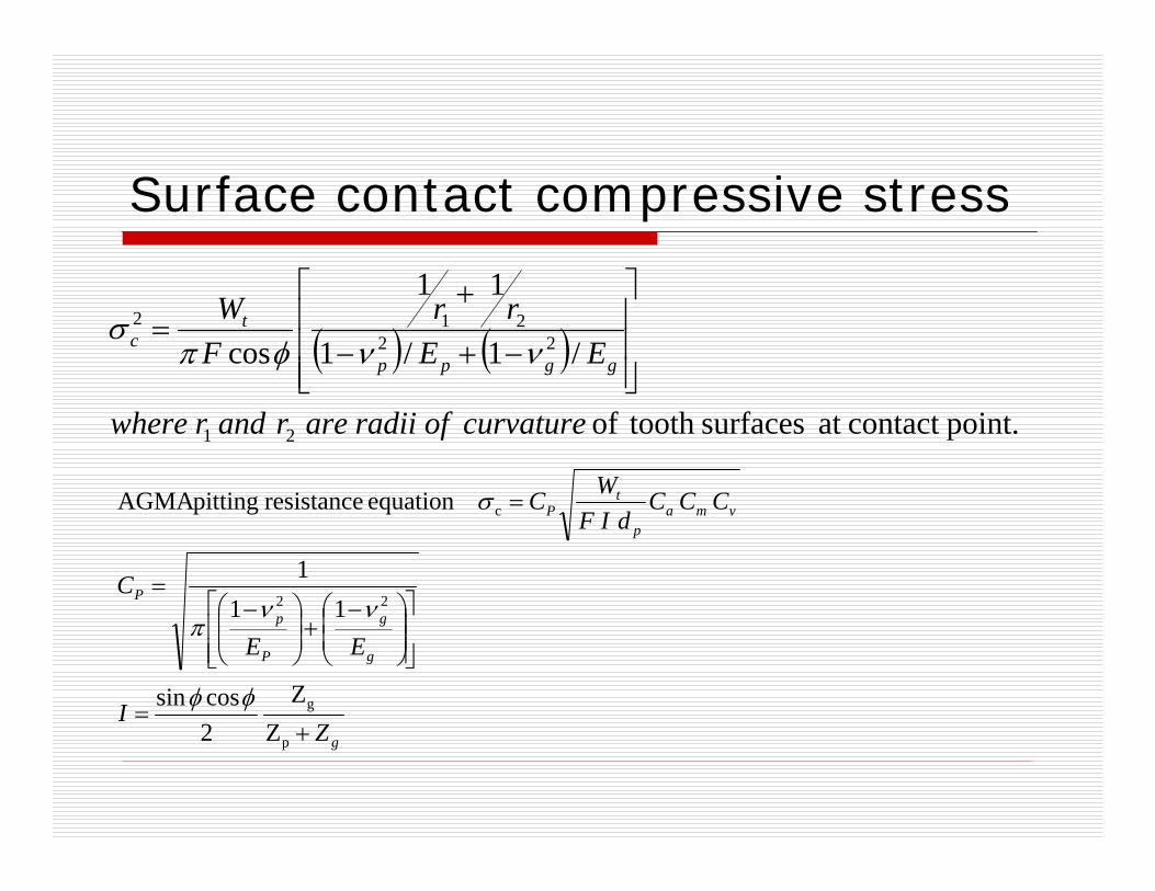
Surface contact compressive stress
( ) ( )point.contact at surfaces tooth of
/1/1
11
cos
21
22212
curvatureofradiiarerandrwhere
EErr
FW
ggpp
tc
⎥⎥⎥
⎦
⎤
⎢⎢⎢
⎣
⎡
−+−
+=
ννφπσ
Z
Z
2cossin
111
equation resistance pittingAGMA
p
g
22
c
g
g
g
P
pP
vmap
tP
ZI
EE
C
CCCdIF
WC
+=
⎥⎥⎦
⎤
⎢⎢⎣
⎡⎟⎟⎠
⎞⎜⎜⎝
⎛ −+⎟⎟⎠
⎞⎜⎜⎝
⎛ −=
=
φφ
ννπ
σ
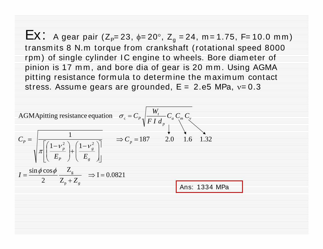
Ex: A gear pair (ZP=23, φ=20°, Zg =24, m=1.75, F=10.0 mm) transmits 8 N.m torque from crankshaft (rotational speed 8000 rpm) of single cylinder IC engine to wheels. Bore diameter of pinion is 17 mm, and bore dia of gear is 20 mm. Using AGMA pitting resistance formula to determine the maximum contact stress. Assume gears are grounded, E = 2.e5 MPa, ν=0.3
0.0821I Z
Z
2cossin
1.32 1.6 2.0 18711
1
equation resistance pittingAGMA
p
g
22
c
=⇒+
=
=⇒
⎥⎥⎦
⎤
⎢⎢⎣
⎡⎟⎟⎠
⎞⎜⎜⎝
⎛ −+⎟⎟⎠
⎞⎜⎜⎝
⎛ −=
=
g
p
g
g
P
pP
vmap
tP
ZI
C
EE
C
CCCdIF
WC
φφ
ννπ
σ
Ans: 1334 MPa

Contact Stress vs. BrinellHardness
Effect of Brinell Hardness on allowable contact stress for through-hardened steel.
For 400 BHN of close quality controlled steel, allowable contact stress = 1150 MPa.
If we use this material for previous example (slide 136), then factor of safety:
0.8621.
HOW TO INCREASE FACTOR OF SAFETY??
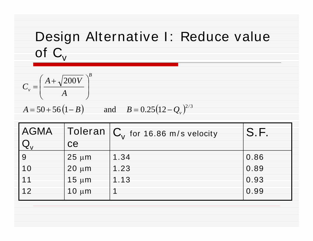
Design Alternative I: Reduce value of Cv
( ) ( ) 3/21225.0 and 15650
200
v
B
v
QBBA
AVA
C
−=−+=
⎟⎟⎠
⎞⎜⎜⎝
⎛ +=
1.341.231.131
Cv for 16.86 m/s velocity
25 μm20 μm15 μm10 μm
Tolerance
0.860.890.930.99
9101112
S.F.AGMA Qv
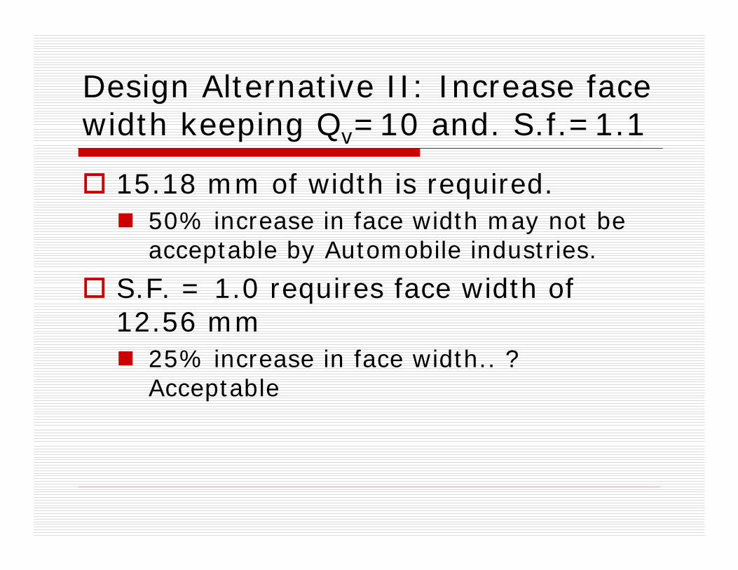
Design Alternative II: Increase face width keeping Qv=10 and. S.f.=1.1
15.18 mm of width is required.50% increase in face width may not be acceptable by Automobile industries.
S.F. = 1.0 requires face width of 12.56 mm
25% increase in face width.. ? Acceptable

Design Alternative III: Increase Case Hardness
Carburization and case hardening increases the hardness of gear ranging 55-64 HRC (~ 1250 to 1300 MPa). However, strength depends on the life of operation and it decreases with increase in operational life.
0178.03558.1 −= cycleL NK
1.0180.9770.938
KL
0.990.950.91
107
108
109
S.F. =1250*KL/σc
Ncycle