24V Solar Charger Instructions - activeforever.com 02-Manual.pdf · Installing the Solar Charger on...
15
Copyright © 2015 Aqua Creek Products All Rights Reserved Revised 5/1/15 PART #: F-044SCH (For use with Pro Pool, Ranger, Pro Pool-XR & Pathfinder) MANDATORY – LEAVE THIS MANUAL WITH LIFT OWNER 24V Solar Charger Instructions Read & follow all instructions Lift safety can only be ensured if the lift is installed and operated according to these instructions For safety reasons, NEVER swim alone SAVE a copy of these instructions NEVER use the lift with a dry pool NEVER apply direct water pressure to the electronics NEVER permit children to play on or around the lift Do not allow children to use the lift without adult supervision 9889 Garrymore Ln Missoula, MT 59808 888-687-3552 | +1-406-549-0769 aquacreek.com 1
Transcript of 24V Solar Charger Instructions - activeforever.com 02-Manual.pdf · Installing the Solar Charger on...

Copyright © 2015 Aqua Creek Products All Rights Reserved Revised 5/1/15
PART #: F-044SCH(For use with Pro Pool, Ranger,
Pro Pool-XR & Pathfinder)
MANDATORY – LEAVE THIS MANUAL WITH LIFT OWNER
24V Solar ChargerInstructions
Read & follow all instructionsLift safety can only be ensured if the lift is installed and operated according to these instructions
For safety reasons, NEVER swim alone
SAVE a copy of these instructions
NEVER use the lift with a dry pool
NEVER apply direct water pressure to the electronics
NEVER permit children to play on or around the liftDo not allow children to use the lift without adult supervision
9889 Garrymore LnMissoula, MT 59808
888-687-3552 | +1-406-549-0769aquacreek.com 1

Copyright © 2015 Aqua Creek Products All Rights Reserved Revised 5/1/15
Unpacking and Assembly
LOWER MAST
UPPER MAST
1/4" X 1-1/2"HEX BOLT
1/4" FLATWASHER (2)
1/4" FLATWASHER (2)
1/4" X 1-3/4"HEX BOLT
1/4" NYLOCKNUT
1/4" NYLOCKNUT
BATTERY CABLE
CONNECTTUBE
FLIP UP
BATTERY CABLEDO NOT PINCH!
CHARGE CONNECTOR
LOWER MAST
UPPER MAST
SOLAR-PANELASSEMBLY
BATTERY CABLE
BATTERY CABLE
CONNECT TUBE
CHARGE CONNECTOR
A
FLIP-UP
SOLAR PANELASSEMBLY
SOLAR CHARGECONTROLLER
MOUNTING POST( 1/2"-13 THREAD)
To assemble the Solar Charger you will need two (2) 7/16” wrenches or sockets.
The 24V Solar-Charger comes fully wired, in two halves for shipping. To assemble the charger remove it from the shipping box and connect the UPPER MAST to the LOWER MAST by flipping the UPPER MAST up and sliding the CONNECT TUBE inside the UPPER MAST and aligning the holes as shown above. Pull the BATTERY CABLE and the CHARGE CONNECTOR through the tube as you slide the TOP ASSEMBLY down. DO NOT PINCH THE BATTERY CABLE! Install the supplied 1/4” x 1 1/2” hex bolt, the flat washers and Nylock-nut as shown. Tighten until snug.
Next, flip-up the SOLAR PANEL ASSEMBLY until it is flat-horizontal, and install the 1/4” x 1 3/4” hex bolt and flat washer underneath as shown. Install the 2nd flat washer and the Nylock nut on the opposite side, and tighten until snug. The Solar Charger is now ready to install on your pool lift.
2

Copyright © 2015 Aqua Creek Products All Rights Reserved Revised 5/1/15
Pro Pool & Ranger Installation
REMOVE THIS1/2" HEX BOLT
AT-SERIESPRO POOLOR RANGER
THREAD INTOANCHOR INSERTTIGHTEN W/1" WRENCH
BATTERY CABLERUNS BACK, ALONGMAIN FRAME &UP ACTUATOR-FRAME, BEHINDCONTROL-BOX
MAINFRAME
ACTUATOR FRAME
CONTROL BOX
CHARGECONNECTORPLUGS INTOCONTROL BOX
NOTE: RUN BATTERY CABLE AS SHOWN;ALONG MAIN FRAME & UP ACTUATORFRAME - TO MAKE SURE IT MOVES WITHTHE LIFT AS IT GOES UP AND DOWN.
To install the Solar Charger on a Pro Pool-AT or Ranger-AT lift;
STEP 1: Remove the 1/2” hex bolt from the baseplate as shown above.STEP 2: Place the 24V Solar Charger over the baseplate of the lift as shown.STEP 3: Align the mounting stud with the baseplate & anchor insert. Thread the mounting stud into the anchor insert and tighten. Use a 1” wrench to make sure it is snug.STEP 4: Run the BATTERY CABLE under the MAIN FRAME TUBE as shown. It will run to the CONTROL BOX, and the CONNECTOR will plug into the control box.(See INSTALLING THE CHARGE CONNECTOR).
3

Copyright © 2015 Aqua Creek Products All Rights Reserved Revised 5/1/15
Pro Pool-XR Installation
1/2" FLATWASHER
REMOVE 1/2"HEX BOLT
PRO POOL-XR
NOTE: MAKE SURE TO RUNBATTERY CABLE ALONGBASE AND MAIN FRAMES& UP ACTUATOR FRAMEAS SHOWN SO CABLE GOESUP & DOWN WITH THE LIFT.
BATTERY CABLE RUNSALONG BASE FRAME,BACK UNDER MAIN FRAME& UP THE ACTUATOR FRAME
BASE FRAME
MAIN FRAME
ACTUATORFRAME
CONTROLBOX
BATTERY
THREAD INTOANCHOR INSERT& TIGHTEN WITH1" WRENCH
CHARGECONNECTORPLUGS INTO
CONTROL BOX
To install the Solar Charger on a Pro Pool-XR lift;
STEP 1: Remove the 1/2” hex bolt from the back anchor insert as shown above.STEP 2: Place the 24V Solar Charger over the base frame where the bolt was removed.STEP 3: Align the mounting stud with the base frame & anchor insert. Thread the mounting stud into the anchor insert and tighten. Use a 1” wrench to make sure it is snug.STEP 4: Run the BATTERY CABLE along the base frame, back under the main frame, and up the actuator frame as shown. The battery cable runs behind the CONTROL BOX, and the CONNECTOR will plug into the control box (see INSTALLING THE CHARGE CONNECTOR).
4
Copyright © 2015 Aqua Creek Products All Rights Reserved Revised 5/1/15
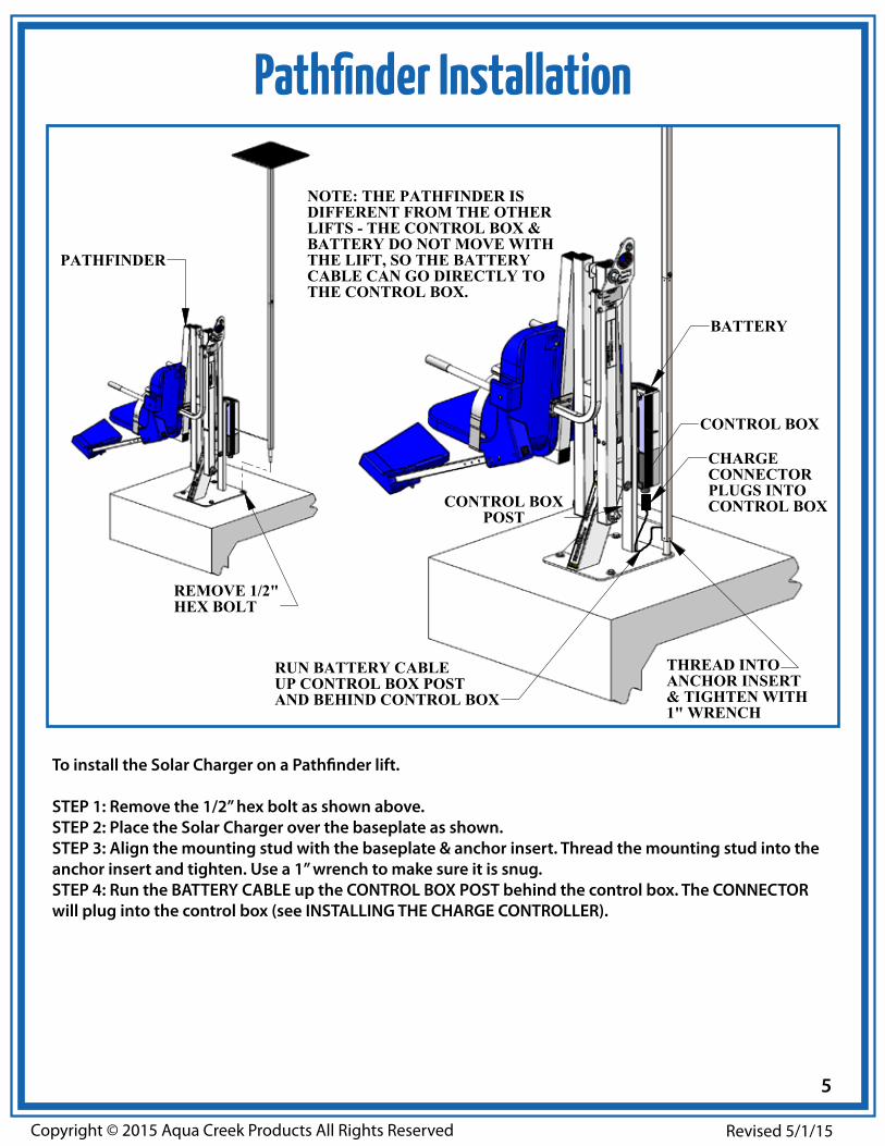
Pathfinder Installation
REMOVE 1/2"HEX BOLT
PATHFINDER
THREAD INTOANCHOR INSERT& TIGHTEN WITH1" WRENCH
RUN BATTERY CABLEUP CONTROL BOX POSTAND BEHIND CONTROL BOX
CONTROL BOX
BATTERY
CONTROL BOXPOST
NOTE: THE PATHFINDER ISDIFFERENT FROM THE OTHERLIFTS - THE CONTROL BOX &BATTERY DO NOT MOVE WITHTHE LIFT, SO THE BATTERYCABLE CAN GO DIRECTLY TOTHE CONTROL BOX.
CHARGECONNECTORPLUGS INTOCONTROL BOX
To install the Solar Charger on a Pathfinder lift.
STEP 1: Remove the 1/2” hex bolt as shown above.STEP 2: Place the Solar Charger over the baseplate as shown.STEP 3: Align the mounting stud with the baseplate & anchor insert. Thread the mounting stud into the anchor insert and tighten. Use a 1” wrench to make sure it is snug.STEP 4: Run the BATTERY CABLE up the CONTROL BOX POST behind the control box. The CONNECTOR will plug into the control box (see INSTALLING THE CHARGE CONTROLLER).
5

Copyright © 2015 Aqua Creek Products All Rights Reserved Revised 5/1/15
Original Pro Pool & Ranger Installation
REMOVE THIS1/2" HEX BOLT
ORIGINAL(OLD-STYLE)
PRO POOLOR RANGER
BATTERY CABLERUNS BACK ,ALONG MAIN FRAME& UP ACTUATOR FRAMEBEHIND CONTROL BOX
CONTROL BOX
BATTERY
THREAD INTOANCHOR INSERTTIGHTEN WITH1" WRENCH
MAIN FRAME
ACTUATOR FRAME
NOTE: MAKE SURE TO RUNBATTERY CABLE ALONGTHE MAIN FRAME AND UPTHE ACTUATOR FRAME ASSHOWN SO THAT THE CABLEMOVES UP & DOWNWITH THE LIFT.
CHARGECONNECTORPLUGS INTOCONTROL BOX
Installing the Solar Charger on an original-style Pro Pool/Ranger Lift;
STEP 1: Remove the 1/2” hex bolt from the baseplate as shown above.STEP 2: Place the 24V Solar Charger over the baseplate of the lift as shown.STEP 3: Align the mounting stud with the baseplate & anchor insert. Thread the mounting stud into the anchor insert and tighten. Use a 1” wrench to make sure it is snug.STEP 4: Run the BATTERY CABLE under the MAIN FRAME TUBE as shown. It will run to the CONTROL BOX, and the CONNECTOR will plug into the control box.(See INSTALLING THE CHARGE CONNECTOR).
6

Copyright © 2015 Aqua Creek Products All Rights Reserved Revised 5/1/15
TO OPEN THE CONTROL BOXUSE A TORX T20 DRIVER
Control Box Modification Instructions
“TORX” T20 DRIVER FOR OPENING CONTROL-BOX
REMOVE THE FOUR (4) SCREWS FROM THE TOP OF THE CONTROL BOX: LEAVE SCREWS IN HOLES
Check to make sure the far right plug in does not have a plastic disk at the top of the hole. If it has a plastic disk, follow the instructions on how to remove it. If the hole is clear, skip to “Installing The Charge Connector”.
7
Copyright © 2015 Aqua Creek Products All Rights Reserved Revised 5/1/15
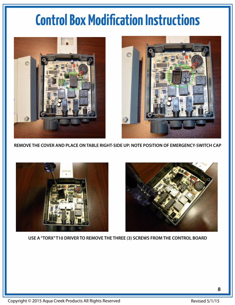
Control Box Modification Instructions
REMOVE THE COVER AND PLACE ON TABLE RIGHT-SIDE UP: NOTE POSITION OF EMERGENCY-SWITCH CAP
USE A “TORX” T10 DRIVER TO REMOVE THE THREE (3) SCREWS FROM THE CONTROL BOARD
8

Copyright © 2015 Aqua Creek Products All Rights Reserved Revised 5/1/15
Control Box Modification Instructions
REMOVE THE CONTROL BOARD FROM THE CONTROL BOX
USE SCREWDRIVER, AND MALLET IF NECESSARY, TO PUNCH-OUT AND REMOVE PLASTIC-DISC ON 24V INPUT/OUTPUT PORT
9

Copyright © 2015 Aqua Creek Products All Rights Reserved Revised 5/1/15
Control Box Modification Instructions
PLACE THE CONTROL BOARD BACK IN PLACE INSIDE THE CONTROL BOX
RETURN THE THREE (3) SCREWS TO SECURETHE CONTROL BOARD BACK IN PLACE
REPLACE THE EMERGENCY-SWITCH CAP WITH “ARROW” POINTING DOWN AS SHOWN
10

Copyright © 2015 Aqua Creek Products All Rights Reserved Revised 5/1/15
Control Box Modification Instructions
PUT COVER ON AND REINSTALL SCREWS
TEST EMERGENCY-SWITCH WITH DRIVER, LISTEN FOR “CLICK”
11

Copyright © 2015 Aqua Creek Products All Rights Reserved Revised 5/1/15
Installing the Charge Connector
STEP 5: Run the BATTERY CABLE behind the control box as shown, and plug the BATTERY CONNECTOR into the control box.
NOTE: The BATTERY CABLE must be run along the main frame as shown so it follows the lift as it goes down into the water. Run the lift up and down to make sure the cable has been installed properly.
12

Copyright © 2015 Aqua Creek Products All Rights Reserved Revised 5/1/15
Solar Charger Operation
CHARGECONTROLLER
(UNDERNEATH)
24VBATTERY
CONTROLBOX
2
WHEN THE BATTERYIS CONNECTED THEINDICATOR WILLFLASH "2" AND THESOLAR CHARGERWILL TURN ON
BATTERY/POWER INDICATOR:TURNS ON (RED) WHEN
THE BATTERY IS CONNECTED
CHARGE INDICATOR:FLASHES SLOWLY (RED)
WHEN BATTERY IS CHARGING
CHARGECONTROLLER
Once the BATTERY CONNECTOR has been installed, and a battery is installed onto the lift the 24V Solar Charger will turn on and start trickle-charging the battery. Without the battery installed the 24V Solar Charger will be off, and will remain off until a battery is installed.
When a 24V battery is installed onto the lift the LED INDICATOR will flash “2” to show that a 24V battery has been detected and the charger is operational.
The Solar-Panel power indicator will light up (red) when the Solar Charger has been properly attached to the battery. The charger will work even on cloudy days, but not as efficiently.
When the battery is installed and there is sufficient sunlight, the CHARGE INDICATOR will flash (red) slowly, indicating the battery is being charged. When the controller detects the battery is fully charged the flashing will stop. Under most conditions the CHARGE INDICATOR light will be flashing whenever a battery has been installed.
The 24V Solar Charger will continue to charge the battery, even as the lift is being used. So once the 24V Solar Charger has been installed it will function without any need for adjustment. The user should check the indicators periodically to make sure it is working.
13

Copyright © 2015 Aqua Creek Products All Rights Reserved Revised 5/1/15
Solar Charger Parts List
1
2
3
9
13
13
13
14
14
15
4
12
11
A
55 6
7
8
9
10
ITEM # QTY PART # DESCRIPTION1 1 PSC-100-00 LOWER MAST ASSEMBLY, PP SOLAR CHARGER
2 1 PSC-200-00 UPPER MAST ASSEMBLY, PP SOLAR CHARGER
3 1 PSC-300-00 TOP PLATE ASSEMBLY, PP SOLAR CHARGER
4 1 VSCC1 CABLE, SOLAR CHARGER CABLE, VITO
5 2 P-WSME-0040 SOLAR PANEL, 4 WATT MOBILE
6 1 P-LCSC-A1 CONTROLLER, 12/24V SOLAR, 10A, IP68 RATING
7 2 222-412 CONNECTOR, WAGO, 2 LEVER
8 1 222-413 CONNECTOR, WAGO, 3 LEVER
9 4 FLAT WASHER, #4 SS WASHER, FLAT, #4, 316 SS
10 4 NYLOCK, #4-40 316 SS NUT, 316 SS, NYLOCK, #4-40
11 1 BOLT, 1/4-20 X 1 1/2 BHSCS BOLT, 316 SS, 1/4-20 X 1 1/2 BHSCS
12 2 BOLT, 1/4-20 X 1 3/4 BHSCS BOLT, 316 SS, 1/4-20 X 1 3/4 BHSCS
13 6 FLAT WASHER, 1/4 SS WASHER, FLAT, 1/4, 316 SS
14 3 NYLOCK, 1/4-20 SS NUT, 316 SS, NYLOCK, 1/4”-20
15 1 GROMMET, 5/16 X 1/2 GROMMET, CHARGER, 5/16 ID X 1/2
14

Copyright © 2015 Aqua Creek Products All Rights Reserved Revised 5/1/15
Revised: 5/1/2015
AQUA CREEK PRODUCTS, LLC LIMITED ONE (1) YEAR WARRANTY:SOLAR CHARGING SYSTEMS
(ITEM #’s F-043SCH, F-044SCH, F-045SCH)
Aqua Creek Products, LLC (a.k.a. Aqua Creek) warrants to the original end user purchaser that products manufactured by Aqua Creek, when properly installed in accordance with assembly and installation instructions and properly used and maintained, shall be free from defects in material and workmanship for a period of one (1) year from the date of original purchase, provided that Aqua Creek receives prompt notice in writing of any defect or failure and satisfactory proof thereof, with the following exceptions:
Exceptions: • All electrical components shall be warranted for a period of ninety (90) days from the date of original purchase.• This warranty specifically excludes reimbursement for labor to remove, repair, or install the product and any freight
charges.• This warranty does not cover any damages due to accident, misuse, abuse, negligence or failure to properly maintain any
products, or normal wear and tear from day to day operations. • In the event that any products are altered, repaired, or improperly installed by anyone without the prior written approval
by Aqua Creek, all warranties are void.
To initiate a warranty claim, the owner of an Aqua Creek product must provide the place of purchase, in writing, with a full description of the product, its serial number, the dates of purchase and installation, and the exact nature of the defect. Within thirty (30) days after receipt of a written warranty claim by Aqua Creek, and barring any unforeseen delays, the place of purchase will be notified of Aqua Creek’s decision regarding the claim. All warranty calculations are from date of original purchase at manufacturer’s suggested retail price. Non-payment for product to Aqua Creek may void warranty.
If requested by Aqua Creek, any defective product must be returned, freight prepaid, to Aqua Creek’s designated factory location or duly appointed distributor for inspection and/or repair. Aqua Creek will, at its option, repair or replace the failed or defective item, and deliver the repaired product or replacement to the seller of the product, freight prepaid to the destination provided for in the original order. Products returned to Aqua Creek for which Aqua Creek provides replacement under this limited warranty shall become the property of Aqua Creek.
A new warranty period shall NOT be established for the repaired or replaced products. Such products shall remain under warranty only for the remainder of the original warranty period on the original products purchased.
This written limited warranty constitutes the final, complete and exclusive statement of warranty terms. No person or organization is authorized to make any other specific or implied warranties or representations on behalf of Aqua Creek.
THE WARRANTIES SET FORTH HEREIN ARE IN LIEU OF ALL OTHER WARRANTIES, EXPRESSED OR IMPLIED, WHICH ARE HEREBY DISCLAIMED AND EXCLUDED, INCLUDING WITHOUT LIMITATION ANY WARRANTY OF MERCHANTABILITY OR FITNESS FOR A PARTICULAR PURPOSE OR USE.
THE SOLE AND EXCLUSIVE REMEDIES FOR BREACH OF ANY AND ALL WARRANTIES WITH RESPECT TO THE PRODUCTS SHALL BE LIMITED TO REPAIR OR REPLACEMENT AT AQUA CREEK’S DESIGNATED FACTORY LOCATION, OR DULY APPOINTED DISTRIBUTOR, OR IN PLACE AT AQUA CREEK’S OPTION. IN NO EVENT SHALL AQUA CREEK’S LIABILITY EXCEED THE ENTIRE AMOUNT PAID TO AQUA CREEK BY THE ORIGINAL PURCHASER FOR THE FAILED OR DEFECTIVE PRODUCT.
IN NO EVENT SHALL AQUA CREEK PRODUCTS, LLC BE LIABLE FOR ANY INCIDENTAL, CONSEQUENTIAL, SPECIAL, INDIRECT, PUNITIVE OR EXEMPLARY DAMAGES OR LOST PROFITS FROM ANY BREACH OF THIS LIMITED WARRANTY OR OTHERWISE.
Aqua Creek Products, LLC9889 Garrymore Lane
Missoula, MT 59808(888) 687-3552 – (406) 549-0769
www.aquacreek.com
15