211steam 0823 2016 - America's BEST Built Boiler · PLACE THE BOILER SECTIONS 15 ... F. APPLY...
63
211A ™ Boilers – Steam Series Gas Installation, Operation & Maintenance Manual
Transcript of 211steam 0823 2016 - America's BEST Built Boiler · PLACE THE BOILER SECTIONS 15 ... F. APPLY...

211A™
Boilers – Steam
SeriesGas
Installation,Operation &MaintenanceManual

USING THIS MANUAL 1A. FOLLOW THE PIPING GUIDELINES . . . . . . .1B. CONTROLS . . . . . . . . . . . . . . . . . . . . . . . . . . .1C. SPECIAL ATTENTION BOXES . . . . . . . . . . . .1
1. PREINSTALLATION 2A. ACCESSIBILITY CLEARANCES . . . . . . . . . . .2B. COMBUSTIBLE CONSTRUCTION
CLEARANCES . . . . . . . . . . . . . . . . . . . . . . . .2C. AIR FOR COMBUSTION & VENTILATION . . .2D. CHIMNEY OR VENT . . . . . . . . . . . . . . . . . . . .5E. BOILER SETTING . . . . . . . . . . . . . . . . . . . . . .7F. WATER QUALITY AND MAKE-UP . . . . . . . . .8G. INSTALLATION SURVEY . . . . . . . . . . . . . . . .8
2. ASSEMBLE THE BASE 10A. BASE ASSEMBLY . . . . . . . . . . . . . . . . . . . .10B. INSTALL THE PILOT BURNERS . . . . . . . . . .11
3. PLACE THE BOILER SECTIONS 15A. PREPARATION . . . . . . . . . . . . . . . . . . . . . . .15B. PLACING THE SECTIONS . . . . . . . . . . . . . .15C. HYDROSTATIC TEST THE BOILER . . . . . . .17
4. INSTALL THE FLUE COLLECTOR 18
5. PIPE THE BOILER 20A. PREPARATION . . . . . . . . . . . . . . . . . . . . . . .20B. SUPPLY PIPING . . . . . . . . . . . . . . . . . . . . . .20C. RETURN PIPING . . . . . . . . . . . . . . . . . . . . . .20D. MULTIPLE BOILER INSTALLATIONS . . . . . .22
6. INSTALL THE JACKET & DRAFT HOOD 24A. PREPARE THE PARTS . . . . . . . . . . . . . . . . .24B. APPLY CLEANOUT COVER PLATES . . . . . .24C. APPLY JACKET END ASSEMBLIES . . . . . .24D. 211A™-04 THROUGH 211A™-08 ONLY . . .24E. 211A™-09 AND LARGER ONLY . . . . . . . . . .24F. APPLY JACKET TOP PANELS . . . . . . . . . . .25G. APPLY LOWER END PANELS . . . . . . . . . . .25H. APPLY PLATES AND LABELS . . . . . . . . . . .25
7. CONNECT GAS PIPING 30A. INSTALL GAS TRAIN . . . . . . . . . . . . . . . . .30
B. CONNECT PILOT GAS TUBING . . . . . . . . . .30C. INSTALL VENT AND BLEED PIPING . . . . . .30D. INSTALL GAS SUPPLY PIPING . . . . . . . . . .31E. TEST GAS SUPPLY PIPING . . . . . . . . . . . . .31
8. INSTALL CONTROLS AND TRIM 33A. INSTALL SAFETY VALVE(S) . . . . . . . . . . . .33B. INSTALL BLOWDOWN VALVES . . . . . . . . .33C. INSTALL LOW WATER CUT-OFF(S) . . . . . .33D. INSTALL PRESSURE CONTROLS . . . . . . . .33
9. WIRE THE BOILER 38A. CONNECT SUPPLY WIRING . . . . . . . . . . . .38B. PREPARE REMAINING CONTROLS . . . . . .38C. INSTALL CONTROL WIRING . . . . . . . . . . . .38
10. STARTING THE BOILER 42A. CHECK THE PIPING . . . . . . . . . . . . . . . . . . .42B. FILL THE BOILER . . . . . . . . . . . . . . . . . . . . .42C. STUDY LIGHTING INSTRUCTIONS . . . . . . .42D. RUN PILOT CHECK-OUT . . . . . . . . . . . . . . .42E. CHECK MAIN BURNER SYSTEM . . . . . . . .42F. CHECK BOILER CONTROLS . . . . . . . . . . . .43G. CLEAN THE BOILER . . . . . . . . . . . . . . . . . . .43
11. LIGHTING INSTRUCTIONS - TYPICAL 44A. TO LIGHT THE BOILER . . . . . . . . . . . . . . . .44B. TO SHUT DOWN THE BOILER . . . . . . . . . .44C. PILOT FLAME FAILURE . . . . . . . . . . . . . . . .44
12. OPERATION & MAINTENANCE 45A. PLACING BOILER IN OPERATION . . . . . . . .46B. TO SHUT DOWN THE BOILER . . . . . . . . . .47C. ANNUAL MAINTENANCE . . . . . . . . . . . . . .47D. MONTHLY MAINTENANCE . . . . . . . . . . . . .47E. WEEKLY MAINTENANCE . . . . . . . . . . . . . .47F. DAILY MAINTENANCE . . . . . . . . . . . . . . . . .47
13. TROUBLESHOOTING - SERVICE TIPS 48
14. BOILER RATINGS & DIMENSIONS 50
15. REPAIR PARTS - SERIES 211A™ 54
TABLE OF CONTENTS
TABLE OF CONTENTS

1
USING THIS MANUAL
A. FOLLOW THE PIPING GUIDELINES
1. We have provided suggested piping diagrams whichwill cover most applications of this boiler.
2. Follow these guidelines to make sure the boiler willoperate correctly.
B. CONTROLS
1. This manual provides wiring diagrams and lightinginstructions for standard systems only.
2. Use the Lighting Instructions and Wiring Diagramsprovided with the boiler to make sure they representthe controls provided.
C. SPECIAL ATTENTION BOXES
1. Throughout this manual you will see specialattention boxes intended to supplement theinstructions and make special notice of potentialhazards. These categories mean, in the judgment ofPB Heat, LLC:
USING THIS MANUAL
Indicates special attention is needed, but not directlyrelated to potential personal injury or propertydamage.
Indicates a condition or hazard which will or cancause minor personal injury or property damage.
Indicates a condition or hazard which will causesevere personal injury, death or major propertydamage.
Indicates a condition or hazard which may causesevere personal injury, death or major propertydamage.
⚠ DANGER
⚠ WARNING
⚠ CAUTION
⚠ NOTICE
2
PREINSTALLATION
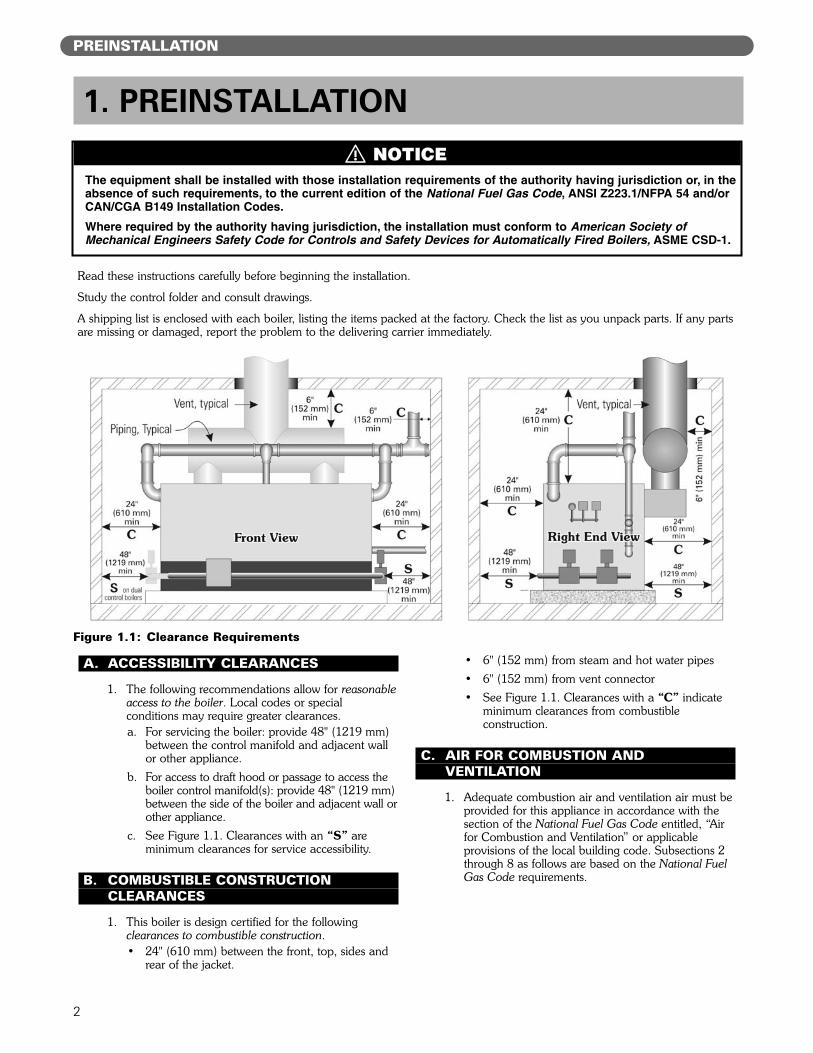
A. ACCESSIBILITY CLEARANCES
1. The following recommendations allow for reasonableaccess to the boiler. Local codes or specialconditions may require greater clearances.a. For servicing the boiler: provide 48" (1219 mm)
between the control manifold and adjacent wallor other appliance.
b. For access to draft hood or passage to access theboiler control manifold(s): provide 48" (1219 mm)between the side of the boiler and adjacent wall orother appliance.
c. See Figure 1.1. Clearances with an “S” areminimum clearances for service accessibility.
B. COMBUSTIBLE CONSTRUCTIONCLEARANCES
1. This boiler is design certified for the followingclearances to combustible construction.• 24" (610 mm) between the front, top, sides and
rear of the jacket.
• 6" (152 mm) from steam and hot water pipes
• 6" (152 mm) from vent connector
• See Figure 1.1. Clearances with a “C” indicateminimum clearances from combustibleconstruction.
C. AIR FOR COMBUSTION ANDVENTILATION
1. Adequate combustion air and ventilation air must beprovided for this appliance in accordance with thesection of the National Fuel Gas Code entitled, “Airfor Combustion and Ventilation” or applicableprovisions of the local building code. Subsections 2through 8 as follows are based on the National FuelGas Code requirements.
1. PREINSTALLATION
The equipment shall be installed with those installation requirements of the authority having jurisdiction or, in theabsence of such requirements, to the current edition of the National Fuel Gas Code, ANSI Z223.1/NFPA 54 and/orCAN/CGA B149 Installation Codes.
Where required by the authority having jurisdiction, the installation must conform to American Society ofMechanical Engineers Safety Code for Controls and Safety Devices for Automatically Fired Boilers, ASME CSD-1.
Read these instructions carefully before beginning the installation.
Study the control folder and consult drawings.
A shipping list is enclosed with each boiler, listing the items packed at the factory. Check the list as you unpack parts. If any partsare missing or damaged, report the problem to the delivering carrier immediately.
Figure 1.1: Clearance Requirements
⚠ NOTICE

3
PREINSTALLATION
2. Required Combustion Air Volume: The total requiredvolume of indoor air is to be the sum of the requiredvolumes for all appliances located within the space.Rooms communicating directly with the space inwhich the appliances are installed and throughcombustion air openings sized as indicated inSubsection 3 are considered part of the requiredvolume. The required volume of indoor air is to bedetermined by one of two methods.
a. Standard Method: The minimum requiredvolume of indoor air (room volume) shall be 50cubic feet per 1000 BTU/Hr (4.8 m3/kW). Thismethod is to be used if the air infiltration rate isunknown or if the rate of air infiltration is knownto be greater than 0.6 air changes per hour. Asan option, this method may be used if the airinfiltration rate is known to be between 0.6 and0.4 air changes per hour. If the air infiltration rateis known to be below 0.4 then the Known AirInfiltration Rate Method must be used. If thebuilding in which this appliance is to be installedis unusually tight, PB Heat recommends that theair infiltration rate be determined.
b. Known Air Infiltration Rate Method:Where the air infiltration rate of a structure isknown, the minimum required volume of indoorair for appliances other than fan assisted and for the Series 211A™ Boiler shall be determined as follows:
where:Iother = Input of appliances other than fan
assisted in Btu/hrACH = air change per hour (percent of the
volume of the space exchanged perhour, expressed as a decimal)
For fan assisted appliances, calculate the requiredvolume of air using the following equation:
Ifan = Input of the fan assisted appliances inBtu/hr
Note: These calculations are not to be used forinfiltration rates greater than 0.60 ACH.
3. Indoor Air Opening Size and Location: Openingsconnecting indoor spaces shall be sized and locatedas follows:a. Combining spaces on the same floor:
Provide two permanent openings communicatingwith additional spaces that have a minimum freearea of 1 in2 per 1000 Btu/hr (22 cm2 per 1000 W)of the total input rating of all gas fired equipmentbut not less than 100 in2 (645 cm2). Oneopening is to begin within 12 inches (305 mm)from the top of the space and the other is tobegin within 12 inches (305 mm) from the floor.The minimum dimension of either of theseopenings shall be 3 inches (76 mm). See Figure1.2 for an illustration of this arrangement.
b. Combining spaces on different floors:Provide one or more permanent openingscommunicating with additional spaces that havea total minimum free area of 2 in2 per 1000Btu/hr (44 cm2 per 1000 W) of total input ratingof all equipment. See Figure 1.3 for anillustration of this arrangement.
4. Outdoor Combustion Air: Outdoor combustion air isto be provided through one or two permanentopenings. The minimum dimension of these airopenings is 3 inches (76 mm).a. Two Permanent Opening Method: Provide
two permanent openings. One opening is tobegin within 12 inches (305 mm) of the top ofthe space and the other is to begin within 12inches (305 mm) of the floor. The openings areto communicate directly or by ducts with theoutdoors or with spaces that freely communicatewith the outdoors. The size of the openings shallbe determined as follows:
21 ft3 IotherACH 1000Btu/hr
Required Volumeother =⎛⎜⎝ ⎛
⎜⎝
Figure 1.2: Air Openings – All Air from Indoorson the Same Floor
Figure 1.3: Air Openings – All Air from Indoorson Different Floors
15 ft3 IfanACH 1000Btu/hr
Required Volumefan =⎛⎜⎝ ⎛
⎜⎝

4
i. Where communicating directly or throughvertical ducts with the outdoors each openingshall have a minimum free area of 1 in2 per4000 Btu/hr (22 cm2 per 4000 W) of totalinput rating for all equipment in the space.See Figure 1.4 for openings directlycommunicating with the outdoors or Figure1.5 for openings connected by ducts to theoutdoors.
ii. Where communicating with the outdoorsthrough horizontal ducts, each opening shallhave a minimum free area of 1 in2 per 2000Btu/hr (22 cm2 per 2000 W) of total ratedinput for all appliances in the space. SeeFigure 1.6.
b. One Permanent Opening Method: Provideone permanent opening beginning within 12inches (305 mm) of the top of the space. Theopening shall communicate directly with theoutdoors, communicate through a vertical orhorizontal duct, or communicate with a spacethat freely communicates with the outdoors. The opening shall have a minimum free area of1 in2 per 3000 Btu/hr of total rated input for allappliances in the space and not less than thesum of the cross-sectional areas of all ventconnectors in the space. The gas-fired equipmentshall have clearances of at least 1 inch (25 mm)from the sides and back and 6 inches (150 mm)from the front of the appliance. See Figure 1.7for this arrangement.
Figure 1.4: Air Openings – All Air Directly fromOutdoors
Figure 1.5: Air Openings – All Air from Outdoorsthrough Vertical Ducts
Figure 1.6: Air Openings – All Air from Outdoorsthrough Horizontal Ducts
Figure 1.7: Air Openings – All Air from Outdoorsthrough One Opening
PREINSTALLATION

5. Combination Indoor and Outdoor Combustion Air: Ifthe required volume of indoor air exceeds theavailable indoor air volume, outdoor air openings orducts may be used to supplement the availableindoor air provided:a. The size and location of the indoor openings
comply with Subsection 3.
b. The outdoor openings are to be located inaccordance with Subsection 4.
c. The size of the outdoor openings are to be sizedas follows:
where:Areq = minimum area of outdoor openings.Afull = full size of outdoor openings calculated
in accordance with Subsection 4.Vavail=available indoor air volumeVreq = required indoor air volume
6. Engineered Installations: Engineered combustion airinstallations shall provide an adequate supply ofcombustion, ventilation, and dilution air and shall beapproved by the authority having jurisdiction.
7. Mechanical Combustion Air Supply:
a. In installations where all combustion air isprovided by a mechanical air supply system, thecombustion air shall be supplied from theoutdoors at the minimum rate of 0.35 ft3/min per1000 Btu/hr (0.034 m3/min per 1000 W) of thetotal rated input of all appliances in the space.
b. In installations where exhaust fans are installed,additional air shall be provided to replace theexhaust air.
c. Each of the appliances served shall beinterlocked to the mechanical air supply toprevent main burner operation when themechanical air supply system is not in operation.
d. In buildings where the combustion air is providedby the mechanical ventilation system, the systemshall provide the specified combustion air rate inaddition to the required ventilation air.
8. Louvers & Grills:
a. The required size of openings for combustion,ventilation, and dilution air shall be based on thenet free area of each opening.
i. Where the free area through a louver or grilleis known, it shall be used in calculating theopening size required to provide the free areaspecified.
ii. Where the free area through a louver or grilleis not known, it shall be assumed that woodenlouvers will have 25% free area and metallouvers and grilles will have 75% free area.
iii. Nonmotorized dampers shall be fixed in theopen position.
b. Motorized dampers shall be interlocked with theequipment so that they are proven in the fullopen position prior to ignition and duringoperation of the main burner.
i. The interlock shall prevent the main burnerfrom igniting if the damper fails to openduring burner startup.
ii. The interlock shall shut down the burner ifthe damper closes during burner operation.
9. Combustion Air Ducts
a. Ducts shall be constructed of galvanized steel oran equivalent corrosion- resistant material.
b. Ducts shall terminate in an unobstructed space,allowing free movement of combustion air to theappliances.
c. Ducts shall serve a single space.
d. Ducts shall not serve both upper and lowercombustion air openings where both suchopenings are used. The separation between ductsserving upper and lower combustion airopenings shall be maintained to the source ofcombustion air.
e. Ducts shall not be screened where terminating inan attic space.
f. Horizontal upper combustion air ducts shall notslope downward toward the source of thecombustion air.
g. The remaining space surrounding a chimneyliner, gas vent, special gas vent, or plastic pipinginstalled within a masonry, metal, or factory built chimney shall not be used to supplycombustion air.
h. Combustion air intake openings located on theexterior of buildings shall have the lowest side ofthe combustion air intake opening at least 12inches (305 mm) above grade.
D. CHIMNEY OR VENT
1. Inspect the existing chimney or vent system. Makesure it is in good condition. Inspect chimney linerand repair or replace if necessary.
2. The vent system and installation must be inaccordance with the current edition of the NationalFuel Gas Code, ANSI Z223.1/NFPA 54, under“Venting of Equipment”, or CAN/CGA B149,Installation codes, under “Venting Systems and AirSupply for Appliances”, or applicable provisions ofthe local building codes.
5
PREINSTALLATION
Vavail1 –Vreq
Areq = Afull ⎛⎜⎝ ⎛
⎜⎝
PREINSTALLATION
3. Chimney/Vent Operation: The vent system must besized and installed to provide the draft needed toremove all combustion products. If the vent systemdoes not provide enough draft, combustion productswill spill into the building from the draft hood reliefopening. If spillage of combustion products occurs,check the vent system, the combustion andventilation openings and make sure the boiler roomis never under negative pressure.
4. Exterior Ventsa. If the vent is outside, make sure it is insulated
sufficiently to ensure adequate draft.
5. Vent Sizing:a. Individual vents: Use vent piping the same
diameter as the boiler vent connection. Theminimum height is 10 feet (305 cm) above thebottom of the draft hood (relief opening). Thevent must also extend above the roof or anyobstructions as outlined in the current edition ofthe National Fuel Gas Code, ANSI Z223.1/NFPA54 and/or CAN/CGA B149, Installation Codes oras required by local codes.
b. Combined vent breeching:
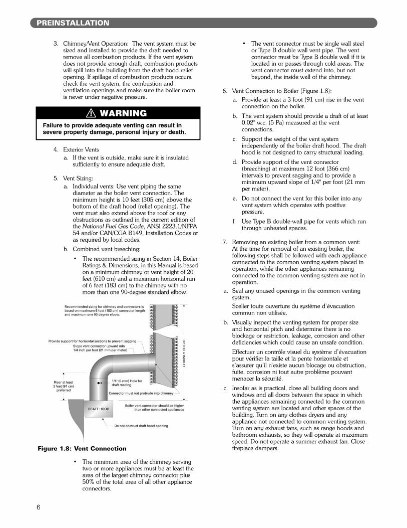
• The recommended sizing in Section 14, BoilerRatings & Dimensions, in this Manual is basedon a minimum chimney or vent height of 20feet (610 cm) and a maximum horizontal runof 6 feet (183 cm) to the chimney with nomore than one 90-degree standard elbow.
• The minimum area of the chimney servingtwo or more appliances must be at least thearea of the largest chimney connector plus50% of the total area of all other applianceconnectors.
• The vent connector must be single wall steelor Type B double wall vent pipe. The ventconnector must be Type B double wall if it islocated in or passes through cold areas. Thevent connector must extend into, but notbeyond, the inside wall of the chimney.
6. Vent Connection to Boiler (Figure 1.8):a. Provide at least a 3 foot (91 cm) rise in the vent
connection on the boiler.
b. The vent system should provide a draft of at least0.02" w.c. (5 Pa) measured at the ventconnections.
c. Support the weight of the vent systemindependently of the boiler draft hood. The drafthood is not designed to carry structural loading.
d. Provide support of the vent connector(breeching) at maximum 12 foot (366 cm)intervals to prevent sagging and to provide aminimum upward slope of 1/4" per foot (21 mmper meter).
e. Do not connect the vent for this boiler into anyvent system which operates with positivepressure.
f. Use Type B double-wall pipe for vents which runthrough unheated spaces.
7. Removing an existing boiler from a common vent:At the time for removal of an existing boiler, thefollowing steps shall be followed with each applianceconnected to the common venting system placed inoperation, while the other appliances remainingconnected to the common venting system are not inoperation.
a. Seal any unused openings in the common ventingsystem.Sceller toute ouverture du système d’évacuationcommun non utilisée.
b. Visually inspect the venting system for proper sizeand horizontal pitch and determine there is noblockage or restriction, leakage, corrosion and otherdeficiencies which could cause an unsafe condition.
Effectuer un contrôle visuel du système d’évacuationpour vérifier la taille et la pente horizontale ets’assurer qu’il n’existe aucun blocage ou obstruction,fuite, corrosion ni tout autre problème pouvantmenacer la sécurité.
c. Insofar as is practical, close all building doors andwindows and all doors between the space in whichthe appliances remaining connected to the commonventing system are located and other spaces of thebuilding. Turn on any clothes dryers and anyappliance not connected to common venting system.Turn on any exhaust fans, such as range hoods andbathroom exhausts, so they will operate at maximumspeed. Do not operate a summer exhaust fan. Closefireplace dampers.
Failure to provide adequate venting can result insevere property damage, personal injury or death.
Figure 1.8: Vent Connection
6
⚠ WARNING

7
PREINSTALLATION
Dans la mesure du possible, fermer toutes les porteset fenêtres de l’immeuble ainsi que toutes les portesentre l’espace dans lequel les appareils quidemeurent raccordés au système d’évacuationcommun se trouvent et le reste de l’immeuble.Mettre en marche les sécheuses et tout autre appareilnon raccordé au système d’évacuation commun.Mettre en marche tous les ventilateurs aspirant, telsque les hottes de cuisinière et les ventilateurs de sallede bain, en les faisant fonctionner à vitessemaximum. Ne pas faire fonctionner les ventilateursaspirant d’été. Fermer les registres de foyers.
d. Place in operation the appliance being inspected.Follow the lighting instructions. Adjust thermostat soappliance will operate continuously.
Mettre en service l’appareil à inspecter. Suivre lesinstructions concernant l’allumage. Régler lethermostat afin que l’appareil fonctionne sans arrêt.
e. Test for spillage at the draft hood relief opening after5 minutes of main burner operation. Use the flameof a match or candle, or smoke from a cigarette,cigar, or pipe.
Vérifier toute fuite à l’orifice de décharge du coupe-tirage après que le brûleur ait fonctionné pendant 5minutes. Utiliser la flamme d’une allumette ou d’unechandelle ou encore la fumée d’une cigarette, d’uncigare ou d’une pipe.
f. After it has been determined that each applianceremaining connected to the common venting systemproperly vents when tested as outlined above, returndoors, windows, exhaust fans, fireplace dampers andany other gas-burning appliance to their previousconditions of use.
Après avoir établi que les résidus de combustion dechaque appareil qui demeure raccordé au systèmecommun sont adéquatement évacués lorsque soumisau test décrit ci-dessus, remettre en place les portes,fenêtres, portes intérieures, ventilateurs aspirants,registres de foyer et appareils fonctionnant au gaz.
g. Any improper operation of the common ventingsystem should be corrected so that the installationconforms with the current edition of the NationalFuel Gas Code, ANSI Z223.1/NFPA 54 and/orCAN/CSA B149.1, Natural Gas and PropaneInstallation Code. When resizing any portion of thecommon venting system, the common ventingsystem should be resized to approach the minimumsize as determined using the appropriate tables in theNational Fuel Gas Code, ANSI Z223.1/NFPA 54and/or CAN/CSA B149.1, Natural Gas and PropaneInstallation Code.
Tout fonctionnement inadéquat du systèmed’évacuation commun doit être corrigé de manière àrespecter les normes du National Fuel Gas Code,ANSI Z223.1/NFPA 54 et/ou des Codes d’installationCAN/ACG B149. Lorsqu’il est nécessaire de modifierles dimensions de toute portion du systèmed’évacuation commun, ces dernières doivent êtremodifiées de manière à respecter les dimensionsminimums indiquées dans les tableaux du chapitre «Sizing of Category I Venting Systems » du NationalFuel Gas Code, ANSI Z223.1/NFPA 54 ou des Codesd’installation CAN/ACG B149.
E. BOILER SETTING
1. Provide a good, level foundation for the boiler withthe minimum dimensions given in Figure 1.9 andTable 1.1. The flooring and structural support systemmust be suitable for the operating weight of theboiler and any connected piping.
2. Do not operate the boiler until the foundation, if newconcrete, has thoroughly cured. The hightemperature under the burners could cause majordamage to the concrete if it still contains moisture.
3. If the boiler is installed in a penthouse or if wiring ofany sort is run underneath the boiler foundation,construct the foundation with provision for airflowunderneath between the main floor and the top ofthe boiler foundation.a. Concrete block aligned with the openings
connected continuously would serve thispurpose, for example.
b. If the foundation must be a concrete slab, use anair cell high temperature insulating board, at least1/2 inch (13 mm) thick, with aluminum backing,aluminum side up. One-half inch (13 mm) HiTemp millboard with aluminum backing wouldbe acceptable as well. Place the insulating boardon the slab inside the base.
Do not install this boiler on carpeting or anycombustible flooring. A significant fire hazard couldresult, with potential for property damage, personalinjury or death.
Figure 1.9: Foundation Layout
⚠ WARNING
8
F. WATER QUALITY AND MAKE-UP
1. Check the system to make sure there are no leaks oroverfilling problems which might cause excessivemake-up water to be added. Make-up water causesliming in the boiler and brings in oxygen. Oxygencan cause severe damage to the boiler throughoxygen corrosion pitting.
2. Clean the boiler as described in this manual. Poorwater quality will cause foaming, priming andoverfilling of the system. Too much sediment in thewater will cause build-up in the boiler and couldresult in cracked sections due to overheating.
3. If the condensate return time lag is too long, thisboiler may not work correctly with gravity return orwith a condensate return unit. Long time lags willcause make-up water to be added to the boiler,resulting in flooding of the boiler, carryover to thesystem and excessive make-up water addition. Youwill need to install a boiler feed system to preventproblems in such cases.
4. Do not use chemicals or substances in theboiler or system which contain petroleum or itsderivatives. This will damage the boiler seals.
G. INSTALLATION SURVEYFor new and existing installations, a Steam InstallationSurvey is available from PB Heat. The survey willprovide information on how a steam boiler works withyour specific system and will provide an overview ofsteam system operation in general.
You can also use this survey to locate system problemswhich will have to be corrected. To obtain copies of theSteam Installation Survey, contact your Peerless®
representative or download from PeerlessBoilers.com.
PREINSTALLATION

9
PREINSTALLATION
Table 1.1: Boiler Foundation Layout
Boiler Boiler Base Length Jacket Length Foundation LengthModel inches mm inches mm inches mm
211A-04 22-1/2 572 28-1/8 714 40-1/8 1,019
211A-05 28-1/8 714 33-3/4 857 45-3/4 1,162
211A-06 33-3/4 857 39-3/8 1,000 51-3/8 1,305
211A-07 39-3/8 1,000 45 1,143 57 1,448
211A-08 45 1,143 50-5/8 1,286 62-5/8 1,591
211A-09 50-5/8 1,286 56-1/4 1,429 68-1/4 1,734
211A-10 56-1/4 1,429 61-7/8 1,572 73-7/8 1,876
211A-11 61-7/8 1,572 67-1/2 1,714 79-1/2 2,019
211A-12 67-1/2 1,714 73-1/8 1,857 85-1/8 2,162
211A-13 73-1/8 1,857 78-3/4 2,000 90-3/4 2,305
211A-14 78-3/4 2,000 84-3/8 2,143 96-3/8 2,448
211A-15 84-3/8 2,143 90 2,286 102 2,591
211A-16 90 2,286 95-5/8 2,429 107-5/8 2,734
211A-17 95-5/8 2,429 101-1/4 2,572 113-1/4 2,877
211A-18 101-1/4 2,572 106-7/8 2,715 118-7/8 3,019
211A-19 106-7/8 2,715 112-1/2 2,857 124-1/2 3,162
211A-20 112-1/2 2,857 118-1/8 3,000 130-1/8 3,305
211A-21 118-1/8 3,000 123-3/4 3,143 135-3/4 3,448
211A-22 123-3/4 3,143 129-3/8 3,286 141-3/8 3,591
211A-23 129-3/8 3,286 135 3,429 147 3,734
211A-24 135 3,429 140-5/8 3,572 152-5/8 3,877
211A-25 140-5/8 3,572 146-1/4 3,715 158-1/4 4,020
211A-26 146-1/4 3,715 151-7/8 3,858 163-7/8 4,162
211A-27 151-7/8 3,858 157-1/2 4,000 169-1/2 4,305
211A-28 157-1/2 4,000 163-1/8 4,143 175-1/8 4,448
211A-29 163-1/8 4,143 168-3/4 4,286 180-7/8 4,594
211A-30 168-3/4 4,286 174-3/8 4,429 186-3/8 4,734
211A-31 174-3/8 4,429 180 4,572 192 4,877
211A-32 180 4,572 185-5/8 4,715 197-5/8 5,020
211A-33 185-5/8 4,715 191-1/4 4,858 203-1/4 5,163
211A-34 191-1/4 4,858 196-7/8 5,001 208-7/8 5,305
211A-35 196-7/8 5,001 202-1/2 5,143 214-1/2 5,448
211A-36 202-1/2 5,143 208-1/8 5,286 220-1/8 5,591
211A-37 208-1/8 5,286 213-3/4 5,429 225-3/4 5,734
211A-38 213-3/4 5,429 219-3/8 5,572 231-3/8 5,877
211A-39 219-3/8 5,572 225 5,715 237 6,020
211A-40 225 5,715 230-5/8 5,858 242-5/8 6,163
211A-41 230-5/8 5,858 236-1/4 6,001 248-1/4 6,306
211A-42 236-1/4 6,001 241-7/8 6,144 253-7/8 6,448
211A-43 241-7/8 6,144 247-1/2 6,286 259-1/2 6,591
211A-44 247-1/2 6,286 253-1/8 6,429 265-1/8 6,734
211A-45 253-1/8 6,429 258-3/4 6,572 270-3/4 6,877
211A-46 258-3/4 6,572 264-3/8 6,715 276-3/8 7,020
10
ASSEMBLE THE BASE
A. BASE ASSEMBLY
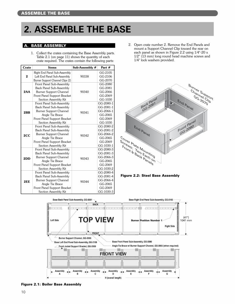
1. Collect the crates containing the Base Assembly parts.Table 2.1 (on page 11) shows the quantity of eachcrate required. The crates contain the following parts:
2. Open crate number 2. Remove the End Panels andmount a Support Channel Clip toward the rear oneach panel as shown in Figure 2.2 using 1/4"-20 x1/2" (13 mm) long round head machine screws and1/4" lock washers provided.
2. ASSEMBLE THE BASE
2
2AA
2BB
2CC
2DD
2EE
Crate
Right End Panel Sub-AssemblyLeft End Panel Sub-Assembly
Burner Support Channel Clips (2)Front Panel Sub-AssemblyBack Panel Sub-AssemblyBurner Support Channel
Front Panel Support BracketSection Assembly Kit
Front Panel Sub-AssemblyBack Panel Sub-AssemblyBurner Support Channel
Angle Tie BraceFront Panel Support Bracket
Section Assembly KitFront Panel Sub-AssemblyBack Panel Sub-AssemblyBurner Support Channel
Angle Tie BraceFront Panel Support Bracket
Section Assembly KitFront Panel Sub-AssemblyBack Panel Sub-AssemblyBurner Support Channel
Angle Tie BraceFront Panel Support Bracket
Section Assembly KitFront Panel Sub-AssemblyBack Panel Sub-AssemblyBurner Support Channel
Angle Tie BraceFront Panel Support Bracket
Section Assembly Kit
Items
90338
90340
90341
90342
90343
90344
Sub-Assembly #
GG-2105GG-2106GG-2070GG-2080GG-2081GG-2066GG-2069GG-1030
GG-2080-1GG-2081-1GG-2066-1GG-2065GG-2069GG-1030
GG-2080-2GG-2081-2GG-2066-2GG-2065GG-2069
GG-1030-1GG-2080-3GG-2081-3GG-2066-3GG-2065GG-2069
GG-1030-2GG-2080-4GG-2081-4GG-2066-4GG-2065GG-2069
GG-1030-3
Part #
Figure 2.2: Steel Base Assembly
Figure 2.1: Boiler Base Assembly

11
ASSEMBLE THE BASE
3. Attach the Front Panel and Back Panel (Figure 2.2) tothe Left Hand End Panel using 5/16"-18 x 1" (25 mm)long cap screws and hex head nuts provided.
4. For 211A™-04 through 211A™-08 Only:a. Complete the base assembly by attaching the
Right End Panel and setting the Burner SupportChannel on the clips.
5. For 211A™-09 through 211A™-46 Only:a. Attach a Front Panel Support Bracket to each
Front Panel as shown in Figure 2.3.
6. Attach an Angle Tie Brace at each panel joint tosecure the front and back panels as shown in Figure2.4 using 5/16"-18 x 1" (25 mm) long cap screwsand hex head nuts.
7. Bolt remaining Front and Back Panels together using5/16"-18 x 1" (25 mm) long cap screws and hex headnuts. See Table 2.1 for panels required. Place thepanels in the positions shown in the table and Figure 2.1.
8. Complete the base assembly by attaching the RightHand End Panel using 5/16"-18 x 1" (25 mm) longcap screws and hex head nuts.
9. Set the Burner Support Channels in place as shownin Figure 2.1.
B. INSTALL THE PILOT BURNERS
1. Check the location of the Burner Support Channelsin the Base Assembly. The dimensions should be:a. Height above boiler foundation: 6-3/4" (171 mm)
b. Distance from back of Base: 3-3/4" (95 mm)
2. Remove the Gas Manifold and Pilot Line Assemblyfrom Box Number 7.
3. Place Manifold on front of Base. Bolt the hangersusing 5/16"-18 x 1" (25 mm) long long cap screwswith 5/16" flat washers. See Figure 2.5.
Figure 2.3: Support Bracket Installation
Figure 2.4: Angle Tie Brace Installation

12
ASSEMBLE THE BASE
Table 2.1: Base Front and Back Panel Crates
ModelA B C D E F G
Number
211A-04 2AA — — — — — — 24-3/4" 629211A-05 2BB — — — — — — 30-3/8" 771211A-06 2CC — — — — — — 36" 914211A-07 2DD — — — — — — 41-5/8" 1,057211A-08 2EE — — — — — — 47-1/4" 1,200211A-09 2BB 2BB — — — — — 52-7/8" 1,343211A-10 2CC 2BB — — — — — 58-1/2" 1,486211A-11 2CC 2CC — — — — — 64-1/8" 1,629211A-12 2DD 2CC — — — — — 69-3/4" 1,772211A-13 2DD 2DD — — — — — 75-3/8" 1,915211A-14 2EE 2DD — — — — — 81" 2,057211A-15 2EE 2EE — — — — — 86-5/8" 2,200211A-16 2CC 2CC 2CC — — — — 92-1/4" 2,343211A-17 2DD 2CC 2CC — — — — 97-7/8" 2,486211A-18 2EE 2CC 2CC — — — — 8'-7-1/2" 2,629211A-19 2DD 2DD 2DD — — — — 9'-1-1/8" 2,772211A-20 2EE 2EE 2CC — — — — 9'-6-3/4" 2,915211A-21 2EE 2EE 2DD — — — — 10'-0-3/8" 3,058211A-22 2EE 2EE 2EE — — — — 10'-6" 3,200211A-23 2EE 2CC 2CC 2CC — — — 10'-11-5/8" 3,343211A-24 2DD 2DD 2DD 2CC — — — 11'-5-1/4" 3,486211A-25 2EE 2EE 2CC 2CC — — — 11'-10-7/8" 3,629211A-26 2EE 2EE 2EE 2BB — — — 12'-4-1/2" 3,772211A-27 2EE 2EE 2EE 2CC — — — 12'-10-1/8" 3,915211A-28 2EE 2EE 2EE 2DD — — — 13'-3-3/4" 4,058211A-29 2EE 2EE 2EE 2EE — — — 13'-9-3/8" 4,201211A-30 2DD 2DD 2DD 2DD 2CC — — 14'-3" 4,343211A-31 2DD 2DD 2DD 2DD 2DD — — 14'-8-5/8" 4,486211A-32 2EE 2DD 2DD 2DD 2DD — — 15'-2-1/4" 4,629211A-33 2EE 2EE 2BB 2EE 2EE — — 15'-7-7/8" 4,772211A-34 2EE 2EE 2EE 2EE 2CC — — 16'-1-1/2" 4,915211A-35 2EE 2EE 2EE 2EE 2DD — — 16'-7-1/8" 5,058211A-36 2EE 2EE 2EE 2EE 2EE — — 17'-0-3/4" 5,201211A-37 2DD 2DD 2DD 2DD 2DD 2DD — 17'-6-3/8" 5,344211A-38 2EE 2DD 2DD 2DD 2DD 2DD — 18'-0" 5,486211A-39 2DD 2DD 2EE 2EE 2DD 2DD — 18'-5-5/8" 5,629211A-40 2BB 2EE 2EE 2EE 2EE 2EE — 18'-11-1/4" 5,772211A-41 2EE 2EE 2DD 2DD 2EE 2EE — 19'-4-7/8" 5,915211A-42 2DD 2EE 2EE 2EE 2EE 2EE — 19'-10-1/2" 6,058211A-43 2EE 2EE 2EE 2EE 2EE 2EE — 20'-4-1/8" 6,201211A-44 2EE 2BB 2EE 2EE 2EE 2BB 2EE 20'-9-3/4" 6,344211A-45 2CC 2BB 2EE 2EE 2EE 2EE 2EE 21'-3-3/8" 6,487211A-46 2CC 2CC 2EE 2EE 2EE 2EE 2EE 21'-9" 6,629
mmfeet/inchesOverall Length
13
ASSEMBLE THE BASE
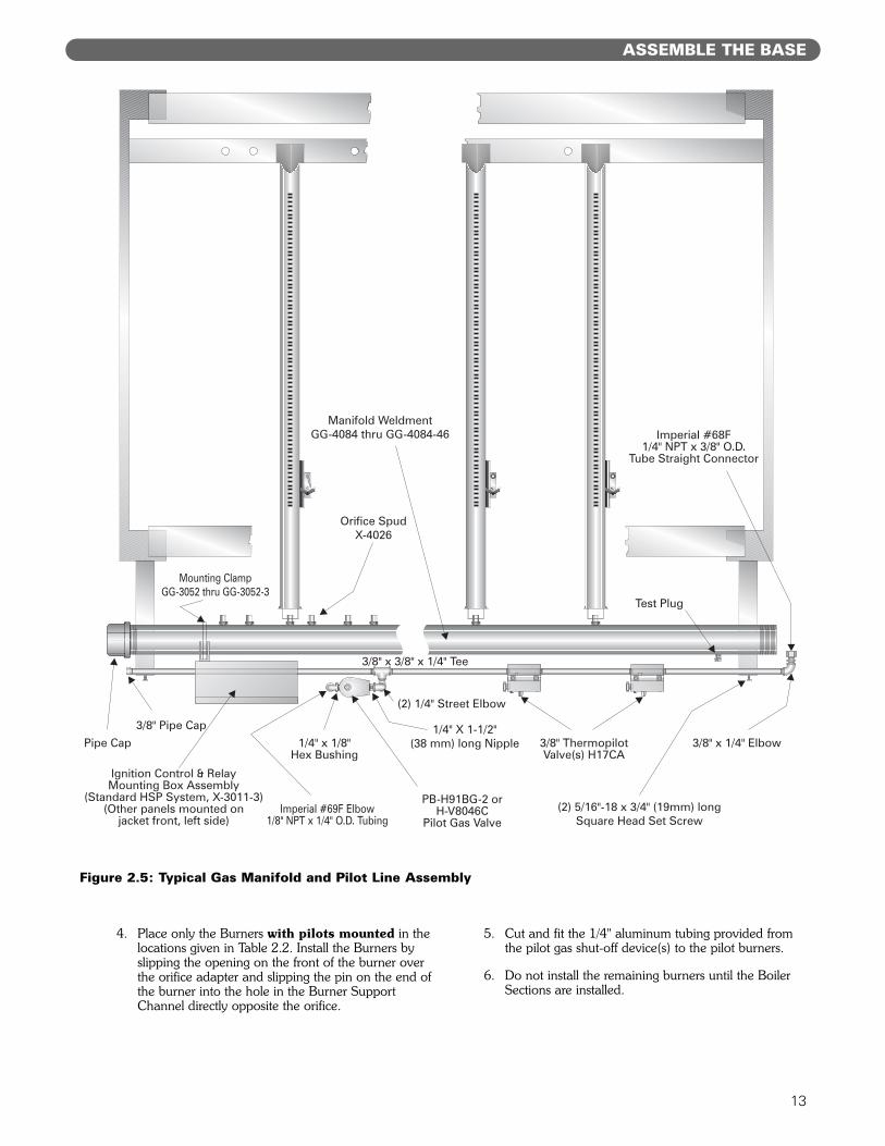
4. Place only the Burners with pilots mounted in thelocations given in Table 2.2. Install the Burners byslipping the opening on the front of the burner overthe orifice adapter and slipping the pin on the end ofthe burner into the hole in the Burner SupportChannel directly opposite the orifice.
5. Cut and fit the 1/4" aluminum tubing provided fromthe pilot gas shut-off device(s) to the pilot burners.
6. Do not install the remaining burners until the BoilerSections are installed.
1/4" X 1-1/2"(38 mm) long Nipple
(2) 1/4" Street Elbow
Imperial #69F Elbow1/8" NPT x 1/4" O.D. Tubing
PB-H91BG-2 orH-V8046C
Pilot Gas Valve
1/4" x 1/8"Hex Bushing
3/8" ThermopilotValve(s) H17CA
(2) 5/16"-18 x 3/4" (19mm) longSquare Head Set Screw
3/8" x 1/4" Elbow
Imperial #68F1/4" NPT x 3/8" O.D.
Tube Straight Connector
Ignition Control & RelayMounting Box Assembly
(Standard HSP System, X-3011-3)(Other panels mounted on
jacket front, left side)
3/8" Pipe Cap
Pipe Cap
Test Plug
Mounting ClampGG-3052 thru GG-3052-3
Orifice SpudX-4026
Manifold WeldmentGG-4084 thru GG-4084-46
3/8" x 3/8" x 1/4" Tee
Figure 2.5: Typical Gas Manifold and Pilot Line Assembly
14
ASSEMBLE THE BASE
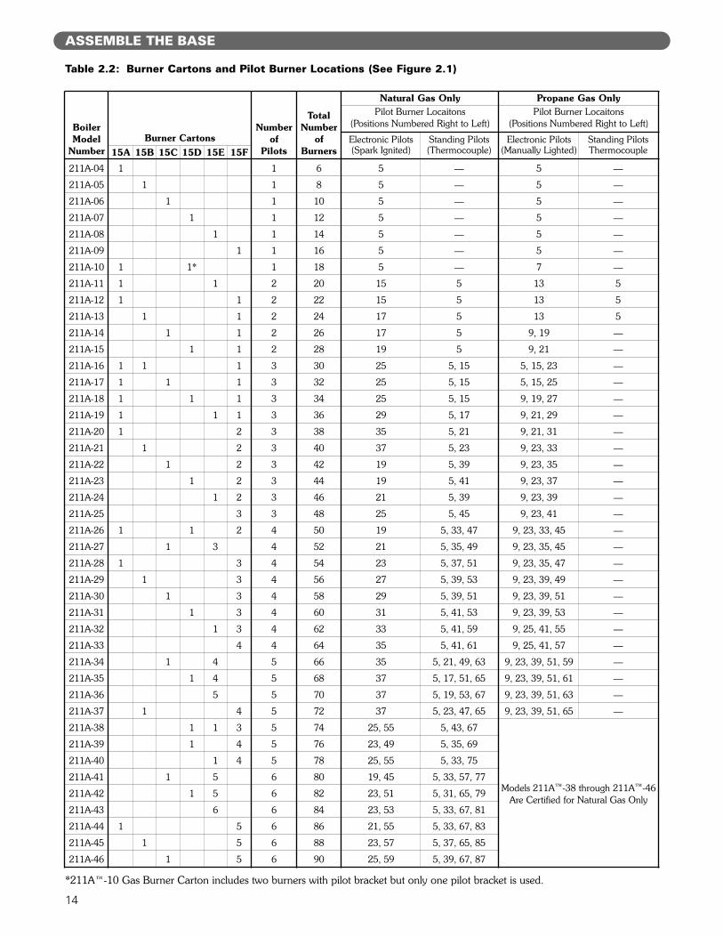
Table 2.2: Burner Cartons and Pilot Burner Locations (See Figure 2.1)
BoilerModel
NumberBurner Cartons
Numberof
Pilots
TotalNumber
ofBurners
Natural Gas Only Propane Gas OnlyPilot Burner Locaitons
(Positions Numbered Right to Left)Pilot Burner Locaitons
(Positions Numbered Right to Left)
Electronic Pilots(Spark Ignited)
Standing Pilots(Thermocouple)
Electronic Pilots(Manually Lighted)
Standing PilotsThermocouple15A 15B 15C 15D 15E 15F
211A-04 1 1 6 5 — 5 —
211A-05 1 1 8 5 — 5 —
211A-06 1 1 10 5 — 5 —
211A-07 1 1 12 5 — 5 —
211A-08 1 1 14 5 — 5 —
211A-09 1 1 16 5 — 5 —
211A-10 1 1* 1 18 5 — 7 —
211A-11 1 1 2 20 15 5 13 5
211A-12 1 1 2 22 15 5 13 5
211A-13 1 1 2 24 17 5 13 5
211A-14 1 1 2 26 17 5 9, 19 —
211A-15 1 1 2 28 19 5 9, 21 —
211A-16 1 1 1 3 30 25 5, 15 5, 15, 23 —
211A-17 1 1 1 3 32 25 5, 15 5, 15, 25 —
211A-18 1 1 1 3 34 25 5, 15 9, 19, 27 —
211A-19 1 1 1 3 36 29 5, 17 9, 21, 29 —
211A-20 1 2 3 38 35 5, 21 9, 21, 31 —
211A-21 1 2 3 40 37 5, 23 9, 23, 33 —
211A-22 1 2 3 42 19 5, 39 9, 23, 35 —
211A-23 1 2 3 44 19 5, 41 9, 23, 37 —
211A-24 1 2 3 46 21 5, 39 9, 23, 39 —
211A-25 3 3 48 25 5, 45 9, 23, 41 —
211A-26 1 1 2 4 50 19 5, 33, 47 9, 23, 33, 45 —
211A-27 1 3 4 52 21 5, 35, 49 9, 23, 35, 45 —
211A-28 1 3 4 54 23 5, 37, 51 9, 23, 35, 47 —
211A-29 1 3 4 56 27 5, 39, 53 9, 23, 39, 49 —
211A-30 1 3 4 58 29 5, 39, 51 9, 23, 39, 51 —
211A-31 1 3 4 60 31 5, 41, 53 9, 23, 39, 53 —
211A-32 1 3 4 62 33 5, 41, 59 9, 25, 41, 55 —
211A-33 4 4 64 35 5, 41, 61 9, 25, 41, 57 —
211A-34 1 4 5 66 35 5, 21, 49, 63 9, 23, 39, 51, 59 —
211A-35 1 4 5 68 37 5, 17, 51, 65 9, 23, 39, 51, 61 —
211A-36 5 5 70 37 5, 19, 53, 67 9, 23, 39, 51, 63 —
211A-37 1 4 5 72 37 5, 23, 47, 65 9, 23, 39, 51, 65 —
211A-38 1 1 3 5 74 25, 55 5, 43, 67
Models 211A™-38 through 211A™-46Are Certified for Natural Gas Only
211A-39 1 4 5 76 23, 49 5, 35, 69
211A-40 1 4 5 78 25, 55 5, 33, 75
211A-41 1 5 6 80 19, 45 5, 33, 57, 77
211A-42 1 5 6 82 23, 51 5, 31, 65, 79
211A-43 6 6 84 23, 53 5, 33, 67, 81
211A-44 1 5 6 86 21, 55 5, 33, 67, 83
211A-45 1 5 6 88 23, 57 5, 37, 65, 85
211A-46 1 5 6 90 25, 59 5, 39, 67, 87
*211A™-10 Gas Burner Carton includes two burners with pilot bracket but only one pilot bracket is used.
15
PLACE THE BOILER SECTIONS
A. PREPARATION
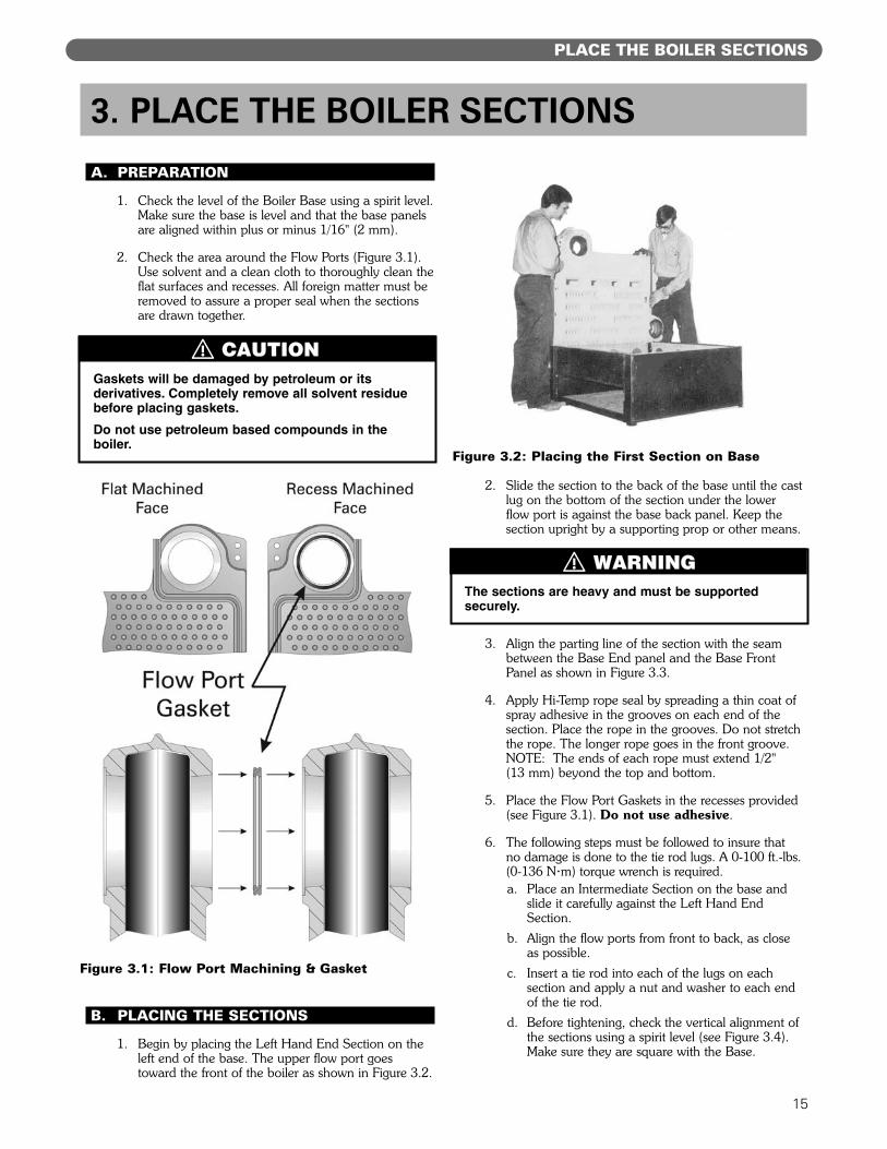
1. Check the level of the Boiler Base using a spirit level.Make sure the base is level and that the base panelsare aligned within plus or minus 1/16" (2 mm).
2. Check the area around the Flow Ports (Figure 3.1).Use solvent and a clean cloth to thoroughly clean theflat surfaces and recesses. All foreign matter must beremoved to assure a proper seal when the sectionsare drawn together.
B. PLACING THE SECTIONS
1. Begin by placing the Left Hand End Section on theleft end of the base. The upper flow port goestoward the front of the boiler as shown in Figure 3.2.
2. Slide the section to the back of the base until the castlug on the bottom of the section under the lowerflow port is against the base back panel. Keep thesection upright by a supporting prop or other means.
3. Align the parting line of the section with the seambetween the Base End panel and the Base FrontPanel as shown in Figure 3.3.
4. Apply Hi-Temp rope seal by spreading a thin coat ofspray adhesive in the grooves on each end of thesection. Place the rope in the grooves. Do not stretchthe rope. The longer rope goes in the front groove.NOTE: The ends of each rope must extend 1/2" (13 mm) beyond the top and bottom.
5. Place the Flow Port Gaskets in the recesses provided(see Figure 3.1). Do not use adhesive.
6. The following steps must be followed to insure thatno damage is done to the tie rod lugs. A 0-100 ft.-lbs.(0-136 N·m) torque wrench is required.a. Place an Intermediate Section on the base and
slide it carefully against the Left Hand EndSection.
b. Align the flow ports from front to back, as closeas possible.
c. Insert a tie rod into each of the lugs on eachsection and apply a nut and washer to each endof the tie rod.
d. Before tightening, check the vertical alignment ofthe sections using a spirit level (see Figure 3.4).Make sure they are square with the Base.
3. PLACE THE BOILER SECTIONS
Gaskets will be damaged by petroleum or itsderivatives. Completely remove all solvent residuebefore placing gaskets.
Do not use petroleum based compounds in theboiler.
The sections are heavy and must be supportedsecurely.
Figure 3.1: Flow Port Machining & Gasket
Figure 3.2: Placing the First Section on Base
⚠ CAUTION
⚠ WARNING

16
Figure 3.3: Assembling Sections on Base
PLACE THE BOILER SECTIONS
17
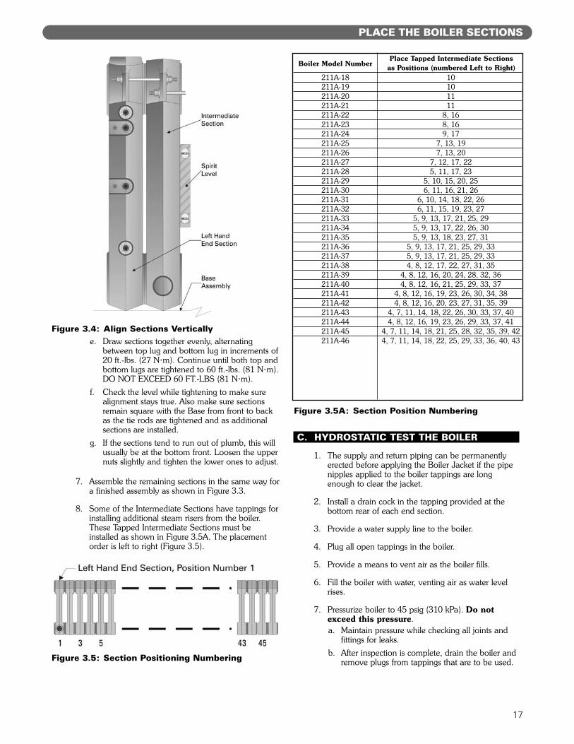
e. Draw sections together evenly, alternatingbetween top lug and bottom lug in increments of20 ft.-lbs. (27 N·m). Continue until both top andbottom lugs are tightened to 60 ft.-lbs. (81 N·m).DO NOT EXCEED 60 FT.-LBS (81 N·m).
f. Check the level while tightening to make surealignment stays true. Also make sure sectionsremain square with the Base from front to backas the tie rods are tightened and as additionalsections are installed.
g. If the sections tend to run out of plumb, this willusually be at the bottom front. Loosen the uppernuts slightly and tighten the lower ones to adjust.
7. Assemble the remaining sections in the same way fora finished assembly as shown in Figure 3.3.
8. Some of the Intermediate Sections have tappings forinstalling additional steam risers from the boiler.These Tapped Intermediate Sections must beinstalled as shown in Figure 3.5A. The placementorder is left to right (Figure 3.5).
C. HYDROSTATIC TEST THE BOILER
1. The supply and return piping can be permanentlyerected before applying the Boiler Jacket if the pipenipples applied to the boiler tappings are longenough to clear the jacket.
2. Install a drain cock in the tapping provided at thebottom rear of each end section.
3. Provide a water supply line to the boiler.
4. Plug all open tappings in the boiler.
5. Provide a means to vent air as the boiler fills.
6. Fill the boiler with water, venting air as water levelrises.
7. Pressurize boiler to 45 psig (310 kPa). Do notexceed this pressure.a. Maintain pressure while checking all joints and
fittings for leaks.
b. After inspection is complete, drain the boiler andremove plugs from tappings that are to be used.
Figure 3.4: Align Sections Vertically
Figure 3.5: Section Positioning Numbering
Boiler Model NumberPlace Tapped Intermediate Sections
as Positions (numbered Left to Right)211A-18 10211A-19 10211A-20 11211A-21 11211A-22 8, 16211A-23 8, 16211A-24 9, 17211A-25 7, 13, 19211A-26 7, 13, 20211A-27 7, 12, 17, 22211A-28 5, 11, 17, 23211A-29 5, 10, 15, 20, 25211A-30 6, 11, 16, 21, 26211A-31 6, 10, 14, 18, 22, 26211A-32 6, 11, 15, 19, 23, 27211A-33 5, 9, 13, 17, 21, 25, 29211A-34 5, 9, 13, 17, 22, 26, 30211A-35 5, 9, 13, 18, 23, 27, 31211A-36 5, 9, 13, 17, 21, 25, 29, 33211A-37 5, 9, 13, 17, 21, 25, 29, 33211A-38 4, 8, 12, 17, 22, 27, 31, 35211A-39 4, 8, 12, 16, 20, 24, 28, 32, 36211A-40 4, 8, 12, 16, 21, 25, 29, 33, 37211A-41 4, 8, 12, 16, 19, 23, 26, 30, 34, 38211A-42 4, 8, 12, 16, 20, 23, 27, 31, 35, 39211A-43 4, 7, 11, 14, 18, 22, 26, 30, 33, 37, 40211A-44 4, 8, 12, 16, 19, 23, 26, 29, 33, 37, 41211A-45 4, 7, 11, 14, 18, 21, 25, 28, 32, 35, 39, 42211A-46 4, 7, 11, 14, 18, 22, 25, 29, 33, 36, 40, 43
Figure 3.5A: Section Position Numbering
PLACE THE BOILER SECTIONS
18
INSTALL THE FLUE COLLECTOR
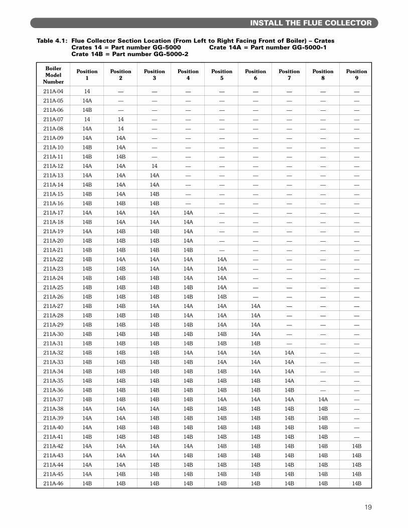
1. Collect the Flue Collector cartons. The Flue Collectorsections are labeled on the part and on the carton.See Table 4.1 for the items needed.
2. Install Hi Temp Rope for each collector section asshown in Figure 4.1. The rope provides the seal toprevent flue gases from leaking from the collector.Make certain that the rope is well under the bottomedges of each flue collector section in order to obtaina tight seal.
3. Place the Flue Collector sections in the positionsgiven in Table 4.1. These positions are numberedfrom left to right when facing the front of theboiler.
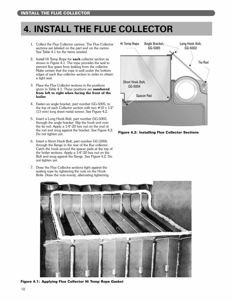
4. Fasten an angle bracket, part number GG-5005, tothe top of each Collector section with two #10 x 1/2"(13 mm) long sheet metal screws. See Figure 4.2.
5. Insert a Long Hook Bolt, part number GG-5003,through the angle bracket. Slip the hook end overthe tie rod. Apply a 1/4"-20 hex nut on the end ofthe rod and snug against the bracket. See Figure 4.2.Do not tighten yet.
6. Insert a Short Hook Bolt, part number GG-5004,through the flange in the rear of the flue collector.Catch the hook around the spacer pads at the top ofthe boiler sections. Apply a 1/4"-20 hex nut on theBolt and snug against the flange. See Figure 4.2. Donot tighten yet.
7. Draw the Flue Collector sections tight against thesealing rope by tightening the nuts on the HookBolts. Draw the nuts evenly, alternating tightening.
4. INSTALL THE FLUE COLLECTOR
Figure 4.2: Installing Flue Collector Sections
Figure 4.1: Applying Flue Collector Hi Temp Rope Gasket
19
INSTALL THE FLUE COLLECTOR
Boiler Position Position Position Position Position Position Position Position PositionModel 1 2 3 4 5 6 7 8 9
Number
211A-04 14 — — — — — — — —
211A-05 14A — — — — — — — —
211A-06 14B — — — — — — — —
211A-07 14 14 — — — — — — —
211A-08 14A 14 — — — — — — —
211A-09 14A 14A — — — — — — —
211A-10 14B 14A — — — — — — —
211A-11 14B 14B — — — — — — —
211A-12 14A 14A 14 — — — — — —
211A-13 14A 14A 14A — — — — — —
211A-14 14B 14A 14A — — — — — —
211A-15 14B 14A 14B — — — — — —
211A-16 14B 14B 14B — — — — — —
211A-17 14A 14A 14A 14A — — — — —
211A-18 14B 14A 14A 14A — — — — —
211A-19 14A 14B 14B 14A — — — — —
211A-20 14B 14B 14B 14A — — — — —
211A-21 14B 14B 14B 14B — — — — —
211A-22 14B 14A 14A 14A 14A — — — —
211A-23 14B 14B 14A 14A 14A — — — —
211A-24 14B 14B 14B 14A 14A — — — —
211A-25 14B 14B 14B 14B 14A — — — —
211A-26 14B 14B 14B 14B 14B — — — —
211A-27 14B 14B 14A 14A 14A 14A — — —
211A-28 14B 14B 14B 14A 14A 14A — — —
211A-29 14B 14B 14B 14B 14A 14A — — —
211A-30 14B 14B 14B 14B 14B 14A — — —
211A-31 14B 14B 14B 14B 14B 14B — — —
211A-32 14B 14B 14B 14A 14A 14A 14A — —
211A-33 14B 14B 14B 14B 14A 14A 14A — —
211A-34 14B 14B 14B 14B 14B 14A 14A — —
211A-35 14B 14B 14B 14B 14B 14B 14A — —
211A-36 14B 14B 14B 14B 14B 14B 14B — —
211A-37 14B 14B 14B 14B 14A 14A 14A 14A —
211A-38 14A 14A 14A 14B 14B 14B 14B 14B —
211A-39 14A 14A 14B 14B 14B 14B 14B 14B —
211A-40 14A 14B 14B 14B 14B 14B 14B 14B —
211A-41 14B 14B 14B 14B 14B 14B 14B 14B —
211A-42 14A 14A 14A 14A 14B 14B 14B 14B 14B
211A-43 14A 14A 14A 14B 14B 14B 14B 14B 14B
211A-44 14A 14A 14B 14B 14B 14B 14B 14B 14B
211A-45 14A 14B 14B 14B 14B 14B 14B 14B 14B
211A-46 14B 14B 14B 14B 14B 14B 14B 14B 14B
Table 4.1: Flue Collector Section Location (From Left to Right Facing Front of Boiler) – CratesCrates 14 = Part number GG-5000 Crate 14A = Part number GG-5000-1Crate 14B = Part number GG-5000-2

20
PIPE THE BOILER
A. PREPARATION
1. The boiler must be pressure tested as outlined inChapter 3, “Place the Boiler Sections,” of thismanual.
2. The Supply and Return piping can be installedbefore the jacket is applied. Use nipples long enoughto be sure they will extend through the jacket.
B. SUPPLY PIPING
1. Install End Riser connections sized per Table 5.1.The 3" tappings in the tops of the end sections arenot used for steam boilers.a. Install a reducing tee on one end riser. Install a 2"
valve, nipple and cap for skimming the boiler inthe tee as shown in the piping drawings.
2. Models 211A™-08 and larger require risers inboth end sections.
3. Models 211A™-18 and larger require additional3" risers off of the tapped intermediate sections. SeeTable 5.1 for the number required.
4. Pipe the header at least 24 inches (610 mm) abovethe normal boiler water line. This is required toprevent water from carrying over into the headerand then to the system.
5. Figure 5.2 shows the Supply and Return piping forParallel Flow Gravity systems and all Pumped ReturnSystems.
6. Counterflow Gravity systems require the boiler steamline to enter the top of the steam main. See Figure5.3 for this special case.
7. The piping in these drawings is shown off the righthand side of the boiler. The boiler may also be pipedtoward the left side as shown in Figure 5.4, typical.
8. Do not reduce the size or number of risersshown. These are required for reliable operation ofthe boiler. If the risers are undersized or incorrectlyplaced, a sloped water line can occur in the boiler,causing possible overheating of some sections.
9. Pipe the Header with an offset as shown in thedrawings. This offset prevents the expansion andcontraction of the Header from damaging the boilersections. Use threaded fittings for swing joints.
10. Always locate the Steam Supply take-offbetween the Equalizer and the last BoilerRiser. (See PB Heat’s “Steam Installation Survey”for discussion). Locating the Steam Supply betweenthe risers will cause water carryover to the system.
11. Do not use a bull head tee to provide steam supplyand equalizer connections. This will cause water levelbounce and carryover.
C. RETURN PIPING
1. The use of a Hartford loop in all installations isrecommended. The loop provides additionalreliability for the system. A check valve must still beinstalled on the pump discharge of all pumped returnsystems.
5. PIPE THE BOILER
Figure 5.1: Supply and Return Positions, Skim Piping, Hartford Loop

21
PIPE THE BOILER
Figure 5.2: Supply and Return Piping – Pumped Return and Parallel Flow Gravity Systems

22
PIPE THE BOILER
2. On pumped return systems, install a boiler cock afterthe pump to allow throttling of the pump discharge.The pressure after the boiler cock should be no morethan 5 psig (35 kPa) above the boiler operatingpressure. Pumping the water into the boiler too fastwill cause collapse of the water level and levelcontrol problems.
3. Size the equalizer per Table 5.1.
4. Pipe the Hartford loop tee so the inside top of theclose nipple is 2 to 4 inches (51 to 102 mm) belowthe boiler water line.
5. If the pump discharge is looped overhead, above theboiler water line, install spring-loaded check valves atboth the pump discharge and the connection to theboiler return.
D. MULTIPLE BOILER INSTALLATIONS
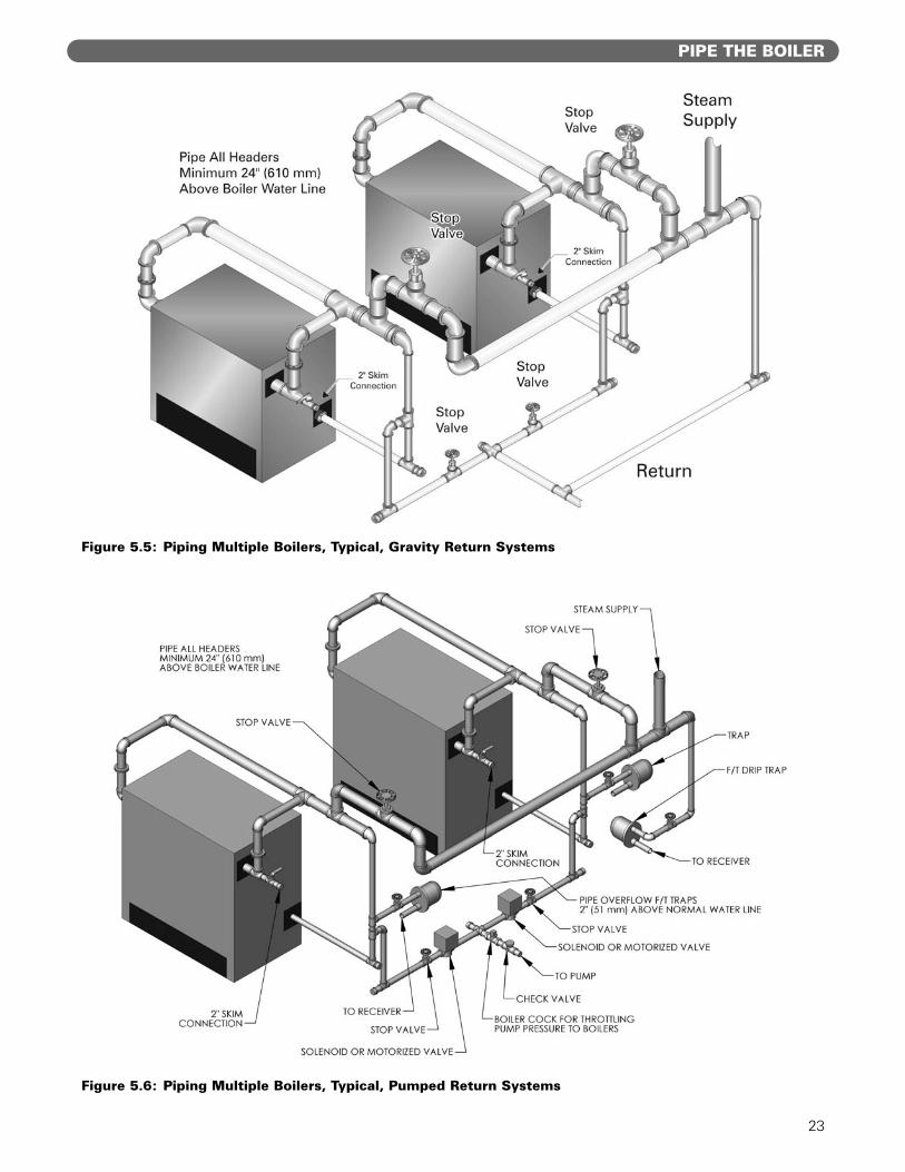
1. Figure 5.5 shows typical piping for multiple boilerGravity Return systems. Figure 5.6 shows typicalpiping for multiple boiler Pumped Return systems.
2. Provide separate feed lines for multiple boilerpumped return systems. Use either separate feedpumps or solenoid valves to isolate feeding of theboilers. This is needed to provide reliable levelcontrol and avoid nuisance performance problems.
3. Condensate return units are not effective for multipleboiler installations since they do not respond to theneeds of the boilers. Always use Boiler feed units.a. Install a Float and Thermostatic trap at the boiler
water level on each of the multiple boilers on apumped return system. This prevents flooding ofidle boilers due to condensation of steam.
Figure 5.4: Left Hand Piping Arrangement – Typical
Figure 5.3: Supply and Return Piping –Counterflow Gravity Systems
Boiler Header End Risers Interm. Risers EqualizersModel Size No. Size No. Size No. Size
211A-04 4" 1 4" - - 1 2-1/2"211A-05 5" 1 5" - - 1 2-1/2"211A-06 5" 1 5" - - 1 2-1/2"211A-07 5" 1 5" - - 1 2-1/2"211A-08 6" 2 5" - - 1 2-1/2"211A-09 6" 2 5" - - 1 2-1/2"211A-10 6" 2 5" - - 1 3"211A-11 6" 2 5" - - 1 3"211A-12 8" 2 5" - - 1 3"211A-13 8" 2 5" - - 1 3"211A-14 8" 2 5" - - 1 3"211A-15 8" 2 6" - - 1 3"211A-16 8" 2 6" - - 2 4"211A-17 8" 2 6" - - 2 4"211A-18 8" 2 6" 1 3" 2 4"211A-19 8" 2 6" 1 3" 2 4"211A-20 8" 2 6" 1 3" 2 4"211A-21 8" 2 6" 1 3" 2 4"211A-22 8" 2 6" 2 3" 2 4"211A-23 8" 2 6" 2 3" 2 4"211A-24 10" 2 6" 2 3" 2 4"211A-25 10" 2 6" 3 3" 2 4"211A-26 10" 2 6" 3 3" 2 4"211A-27 10" 2 6" 4 3" 2 4"211A-28 10" 2 6" 4 3" 2 5"211A-29 10" 2 6" 5 3" 2 5"211A-30 10" 2 6" 5 3" 2 5"211A-31 10" 2 6" 6 3" 2 5"211A-32 10" 2 6" 6 3" 2 5"211A-33 10" 2 6" 7 3" 2 5"211A-34 10" 2 6" 7 3" 2 5"211A-35 10" 2 6" 7 3" 2 5"211A-36 10" 2 6" 8 3" 2 5"211A-37 10" 2 6" 8 3" 2 5"211A-38 10" 2 6" 8 3" 2 5"211A-39 10" 2 6" 9 3" 2 5"211A-40 10" 2 6" 9 3" 2 5"211A-41 10" 2 6" 10 3" 2 5"211A-42 10" 2 6" 10 3" 2 5"211A-43 10" 2 6" 11 3" 2 5"211A-44 12" 2 6" 11 3" 2 5"211A-45 12" 2 6" 12 3" 2 5"211A-46 12" 2 6" 12 3" 2 5"
Table 5.1: Header, Risers & Equalizer Sizing
23
PIPE THE BOILER
Figure 5.6: Piping Multiple Boilers, Typical, Pumped Return Systems
Figure 5.5: Piping Multiple Boilers, Typical, Gravity Return Systems
24
INSTALL THE JACKET & DRAFT HOOD
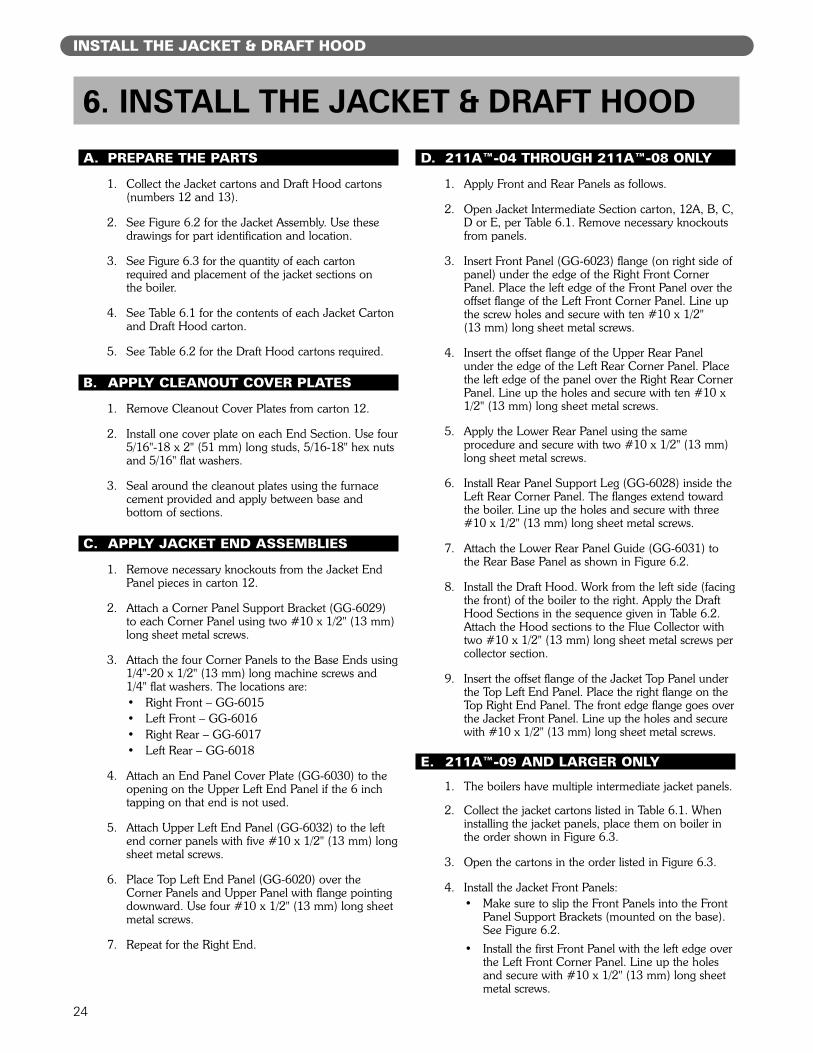
A. PREPARE THE PARTS
1. Collect the Jacket cartons and Draft Hood cartons(numbers 12 and 13).
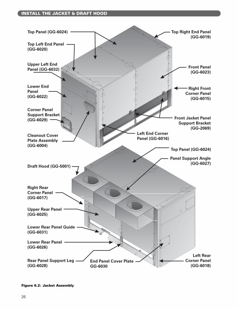
2. See Figure 6.2 for the Jacket Assembly. Use thesedrawings for part identification and location.
3. See Figure 6.3 for the quantity of each cartonrequired and placement of the jacket sections on the boiler.
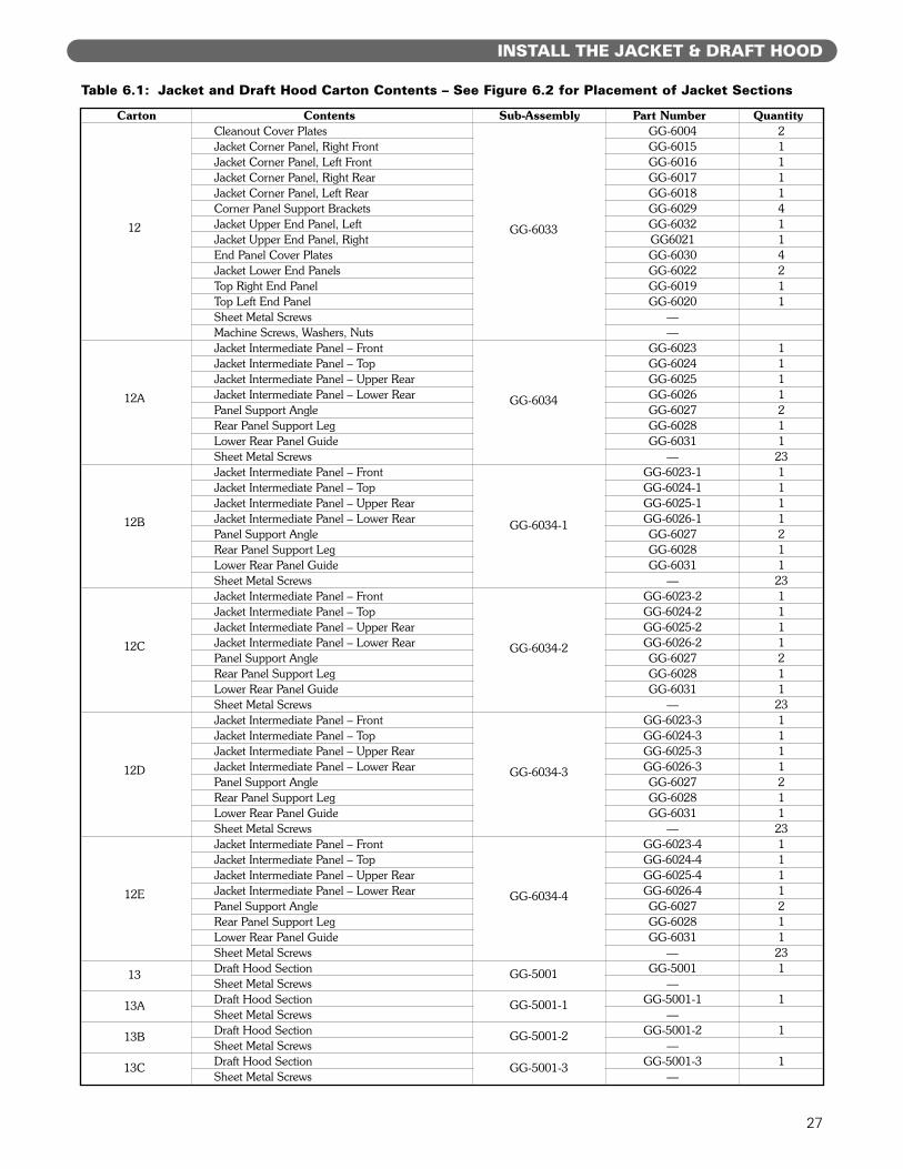
4. See Table 6.1 for the contents of each Jacket Cartonand Draft Hood carton.
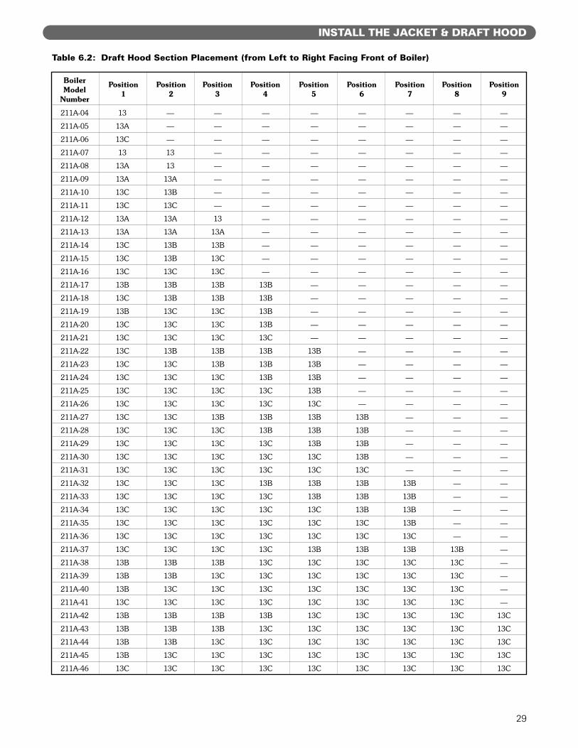
5. See Table 6.2 for the Draft Hood cartons required.
B. APPLY CLEANOUT COVER PLATES
1. Remove Cleanout Cover Plates from carton 12.
2. Install one cover plate on each End Section. Use four5/16"-18 x 2" (51 mm) long studs, 5/16-18" hex nutsand 5/16" flat washers.
3. Seal around the cleanout plates using the furnacecement provided and apply between base andbottom of sections.
C. APPLY JACKET END ASSEMBLIES
1. Remove necessary knockouts from the Jacket EndPanel pieces in carton 12.
2. Attach a Corner Panel Support Bracket (GG-6029)to each Corner Panel using two #10 x 1/2" (13 mm)long sheet metal screws.
3. Attach the four Corner Panels to the Base Ends using1/4"-20 x 1/2" (13 mm) long machine screws and1/4" flat washers. The locations are:• Right Front – GG-6015• Left Front – GG-6016• Right Rear – GG-6017• Left Rear – GG-6018
4. Attach an End Panel Cover Plate (GG-6030) to theopening on the Upper Left End Panel if the 6 inchtapping on that end is not used.
5. Attach Upper Left End Panel (GG-6032) to the leftend corner panels with five #10 x 1/2" (13 mm) longsheet metal screws.
6. Place Top Left End Panel (GG-6020) over theCorner Panels and Upper Panel with flange pointingdownward. Use four #10 x 1/2" (13 mm) long sheetmetal screws.
7. Repeat for the Right End.
D. 211A™-04 THROUGH 211A™-08 ONLY
1. Apply Front and Rear Panels as follows.
2. Open Jacket Intermediate Section carton, 12A, B, C,D or E, per Table 6.1. Remove necessary knockoutsfrom panels.
3. Insert Front Panel (GG-6023) flange (on right side ofpanel) under the edge of the Right Front CornerPanel. Place the left edge of the Front Panel over theoffset flange of the Left Front Corner Panel. Line upthe screw holes and secure with ten #10 x 1/2" (13 mm) long sheet metal screws.
4. Insert the offset flange of the Upper Rear Panelunder the edge of the Left Rear Corner Panel. Placethe left edge of the panel over the Right Rear CornerPanel. Line up the holes and secure with ten #10 x1/2" (13 mm) long sheet metal screws.
5. Apply the Lower Rear Panel using the sameprocedure and secure with two #10 x 1/2" (13 mm)long sheet metal screws.
6. Install Rear Panel Support Leg (GG-6028) inside theLeft Rear Corner Panel. The flanges extend towardthe boiler. Line up the holes and secure with three#10 x 1/2" (13 mm) long sheet metal screws.
7. Attach the Lower Rear Panel Guide (GG-6031) tothe Rear Base Panel as shown in Figure 6.2.
8. Install the Draft Hood. Work from the left side (facingthe front) of the boiler to the right. Apply the DraftHood Sections in the sequence given in Table 6.2.Attach the Hood sections to the Flue Collector withtwo #10 x 1/2" (13 mm) long sheet metal screws percollector section.
9. Insert the offset flange of the Jacket Top Panel underthe Top Left End Panel. Place the right flange on theTop Right End Panel. The front edge flange goes overthe Jacket Front Panel. Line up the holes and securewith #10 x 1/2" (13 mm) long sheet metal screws.
E. 211A™-09 AND LARGER ONLY
1. The boilers have multiple intermediate jacket panels.
2. Collect the jacket cartons listed in Table 6.1. Wheninstalling the jacket panels, place them on boiler inthe order shown in Figure 6.3.
3. Open the cartons in the order listed in Figure 6.3.
4. Install the Jacket Front Panels:• Make sure to slip the Front Panels into the Front
Panel Support Brackets (mounted on the base).See Figure 6.2.
• Install the first Front Panel with the left edge overthe Left Front Corner Panel. Line up the holesand secure with #10 x 1/2" (13 mm) long sheetmetal screws.
6. INSTALL THE JACKET & DRAFT HOOD
25
INSTALL THE JACKET & DRAFT HOOD
• Continue applying Front Panels this way.
• Slip the right edge of the last Front Panel underthe Right Front Corner Panel. Line up the holesand secure with #10 x 1/2" (13 mm) long sheetmetal screws.
5. Install the Jacket Rear Panels:• Slip the offset flange of the first Upper Rear Panel
under the edge of the Left Rear Corner Panel.Secure with #10 x 1/2" (13 mm) long sheetmetal screws.
• Attach the first Lower Rear Panel in the same way.• Attach a Rear Panel Support Leg on the inside of
the Upper Rear Panel. The flanges point towardthe boiler. Attach with #10 x 1/2" (13 mm) longsheet metal screws.
• Install a Panel Support Angle on the inside top ofthe Upper Rear Panel (See Figure 6.2). Use #10x 1/2" (13 mm) long sheet metal screws.
• Install the remaining Upper Rear and Lower RearPanels in the same way.
• Place the edge of the last rear panel over theRight Rear Corner Panel.
6. Install the Draft Hood Sections:• Start from the left of the boiler (facing the front).
Apply the Draft Hood sections from left to rightin the order given in Table 6.2.
• Use two #10 x 1/2" (13 mm) long sheet metalscrews for each Flue Collector section.
F. APPLY JACKET TOP PANELS
1. Apply the jacket top panels working from left to right(facing front of boiler). Place the panels from thecartons in the sequence given in Figure 6.3.
2. Mount a Panel Support Angle (GG-6027) on theback bottom edge of each Top Panel with the longflange pointed down. Peel the insulation slightlyaway from the back edge of the panel for bettercontact. Secure with one #10 x 1/2" (13 mm) longsheet metal screw.
3. Slide the left hand offset flange of the first Top Panelunder the Top Left End Panel. Place the front flangeof the Top Panel over the Front Panel. Line up theholes and secure with #10 x 1/2" (13 mm) longsheet metal screws.
4. Slide the left hand edge of each additional panelunder the panel to its left. Secure with #10 x 1/2"(13 mm) long sheet metal screws.
5. Apply the last Top Panel in the same way. Place itsright hand edge over the Top Right End Panel. Securewith #10 x 1/2" (13 mm) long sheet metal screws.
6. Check for loose or missing screws as you completethe jacket assembly.
G. APPLY LOWER END PANELS
1. THIS APPLIES TO ALL BOILER SIZES.
2. The parts are packed in carton #12.
3. Attach an End Panel Cover Plate to the opening inthe Lower End Panel (GG-6022) if the tapping in theboiler is not being used. Secure with two #10 x 1/2"(13 mm) long metal screws.
4. Apply a Lower End Panel to each end of the boiler,securing to the Corner Panels with eight #10 x ½”(13 mm) long sheet metal screws. Attach to theUpper End Panels with two #10 x ½” (13 mm) longsheet metal screws.
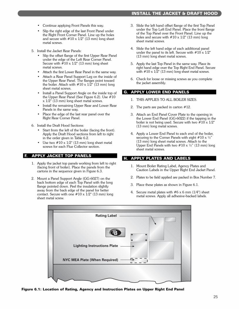
H. APPLY PLATES AND LABELS
1. Mount Boiler Rating Label, Agency Plates andCaution Labels in the Upper Right End Jacket Panel.
2. Plates to be field applied are packed in Box Number 7.
3. Place these plates as shown in Figure 6.1.
4. Secure metal plates with #6 x 6 mm (1/4") sheetmetal screws. Apply all adhesive-backed labels.
FIGURE 28
Figure 6.1: Location of Rating, Agency and Instruction Plates on Upper Right End Panel
26
INSTALL THE JACKET & DRAFT HOOD
Top Panel (GG-6024)
Panel Support Angle(GG-6027)
End Panel Cover PlateGG-6030
Draft Hood (GG-5001)
Right RearCorner Panel(GG-6017)
Left RearCorner Panel
(GG-6018)
Upper Rear Panel(GG-6025)
Lower Rear Panel Guide(GG-6031)
Lower Rear Panel(GG-6026)
Rear Panel Support Leg(GG-6028)
Top Panel (GG-6024) Top Right End Panel(GG-6019)
Front Panel(GG-6023)
Right FrontCorner Panel
(GG-6015)
Front Jacket PanelSupport Bracket
(GG-2069)
Top Left End Panel(GG-6020)
Upper Left EndPanel (GG-6032)
Lower EndPanel(GG-6022)
Corner PanelSupport Bracket(GG-6029)
Cleanout CoverPlate Assembly(GG-6004)
Left End CornerPanel (GG-6016)
Figure 6.2: Jacket Assembly
27
INSTALL THE JACKET & DRAFT HOOD
Carton Contents Sub-Assembly Part Number QuantityCleanout Cover Plates GG-6004 2Jacket Corner Panel, Right Front GG-6015 1Jacket Corner Panel, Left Front GG-6016 1Jacket Corner Panel, Right Rear GG-6017 1Jacket Corner Panel, Left Rear GG-6018 1Corner Panel Support Brackets GG-6029 4
12 Jacket Upper End Panel, Left GG-6032 1Jacket Upper End Panel, Right GG6021 1End Panel Cover Plates GG-6030 4Jacket Lower End Panels GG-6022 2Top Right End Panel GG-6019 1Top Left End Panel GG-6020 1Sheet Metal Screws —Machine Screws, Washers, Nuts —Jacket Intermediate Panel – Front GG-6023 1Jacket Intermediate Panel – Top GG-6024 1Jacket Intermediate Panel – Upper Rear GG-6025 1
12A Jacket Intermediate Panel – Lower Rear GG-6026 1Panel Support Angle GG-6027 2Rear Panel Support Leg GG-6028 1Lower Rear Panel Guide GG-6031 1Sheet Metal Screws — 23Jacket Intermediate Panel – Front GG-6023-1 1Jacket Intermediate Panel – Top GG-6024-1 1Jacket Intermediate Panel – Upper Rear GG-6025-1 1
12B Jacket Intermediate Panel – Lower Rear GG-6026-1 1Panel Support Angle GG-6027 2Rear Panel Support Leg GG-6028 1Lower Rear Panel Guide GG-6031 1Sheet Metal Screws — 23Jacket Intermediate Panel – Front GG-6023-2 1Jacket Intermediate Panel – Top GG-6024-2 1Jacket Intermediate Panel – Upper Rear GG-6025-2 1
12C Jacket Intermediate Panel – Lower Rear GG-6026-2 1Panel Support Angle GG-6027 2Rear Panel Support Leg GG-6028 1Lower Rear Panel Guide GG-6031 1Sheet Metal Screws — 23Jacket Intermediate Panel – Front GG-6023-3 1Jacket Intermediate Panel – Top GG-6024-3 1Jacket Intermediate Panel – Upper Rear GG-6025-3 1
12D Jacket Intermediate Panel – Lower Rear GG-6026-3 1Panel Support Angle GG-6027 2Rear Panel Support Leg GG-6028 1Lower Rear Panel Guide GG-6031 1Sheet Metal Screws — 23Jacket Intermediate Panel – Front GG-6023-4 1Jacket Intermediate Panel – Top GG-6024-4 1Jacket Intermediate Panel – Upper Rear GG-6025-4 1
12E Jacket Intermediate Panel – Lower Rear GG-6026-4 1Panel Support Angle GG-6027 2Rear Panel Support Leg GG-6028 1Lower Rear Panel Guide GG-6031 1Sheet Metal Screws — 23
13 Draft Hood Section GG-5001 1Sheet Metal Screws —
13A Draft Hood Section GG-5001-1 1Sheet Metal Screws —
13B Draft Hood Section GG-5001-2 1Sheet Metal Screws —
13C Draft Hood Section GG-5001-3 1Sheet Metal Screws —
GG-6033
GG-6034
GG-6034-1
GG-6034-2
GG-6034-3
GG-6034-4
GG-5001
GG-5001-1
GG-5001-2
GG-5001-3
Table 6.1: Jacket and Draft Hood Carton Contents – See Figure 6.2 for Placement of Jacket Sections

28
INSTALL THE JACKET & DRAFT HOOD
Figure 6.3: Jacket Assembly Sequence - Carton Numbers and Locations
29
INSTALL THE JACKET & DRAFT HOOD
Boiler Position Position Position Position Position Position Position Position PositionModel 1 2 3 4 5 6 7 8 9
Number
211A-04 13 — — — — — — — —
211A-05 13A — — — — — — — —
211A-06 13C — — — — — — — —
211A-07 13 13 — — — — — — —
211A-08 13A 13 — — — — — — —
211A-09 13A 13A — — — — — — —
211A-10 13C 13B — — — — — — —
211A-11 13C 13C — — — — — — —
211A-12 13A 13A 13 — — — — — —
211A-13 13A 13A 13A — — — — — —
211A-14 13C 13B 13B — — — — — —
211A-15 13C 13B 13C — — — — — —
211A-16 13C 13C 13C — — — — — —
211A-17 13B 13B 13B 13B — — — — —
211A-18 13C 13B 13B 13B — — — — —
211A-19 13B 13C 13C 13B — — — — —
211A-20 13C 13C 13C 13B — — — — —
211A-21 13C 13C 13C 13C — — — — —
211A-22 13C 13B 13B 13B 13B — — — —
211A-23 13C 13C 13B 13B 13B — — — —
211A-24 13C 13C 13C 13B 13B — — — —
211A-25 13C 13C 13C 13C 13B — — — —
211A-26 13C 13C 13C 13C 13C — — — —
211A-27 13C 13C 13B 13B 13B 13B — — —
211A-28 13C 13C 13C 13B 13B 13B — — —
211A-29 13C 13C 13C 13C 13B 13B — — —
211A-30 13C 13C 13C 13C 13C 13B — — —
211A-31 13C 13C 13C 13C 13C 13C — — —
211A-32 13C 13C 13C 13B 13B 13B 13B — —
211A-33 13C 13C 13C 13C 13B 13B 13B — —
211A-34 13C 13C 13C 13C 13C 13B 13B — —
211A-35 13C 13C 13C 13C 13C 13C 13B — —
211A-36 13C 13C 13C 13C 13C 13C 13C — —
211A-37 13C 13C 13C 13C 13B 13B 13B 13B —
211A-38 13B 13B 13B 13C 13C 13C 13C 13C —
211A-39 13B 13B 13C 13C 13C 13C 13C 13C —
211A-40 13B 13C 13C 13C 13C 13C 13C 13C —
211A-41 13C 13C 13C 13C 13C 13C 13C 13C —
211A-42 13B 13B 13B 13B 13C 13C 13C 13C 13C
211A-43 13B 13B 13B 13C 13C 13C 13C 13C 13C
211A-44 13B 13B 13C 13C 13C 13C 13C 13C 13C
211A-45 13B 13C 13C 13C 13C 13C 13C 13C 13C
211A-46 13C 13C 13C 13C 13C 13C 13C 13C 13C
Table 6.2: Draft Hood Section Placement (from Left to Right Facing Front of Boiler)
30
CONNECT GAS PIPING
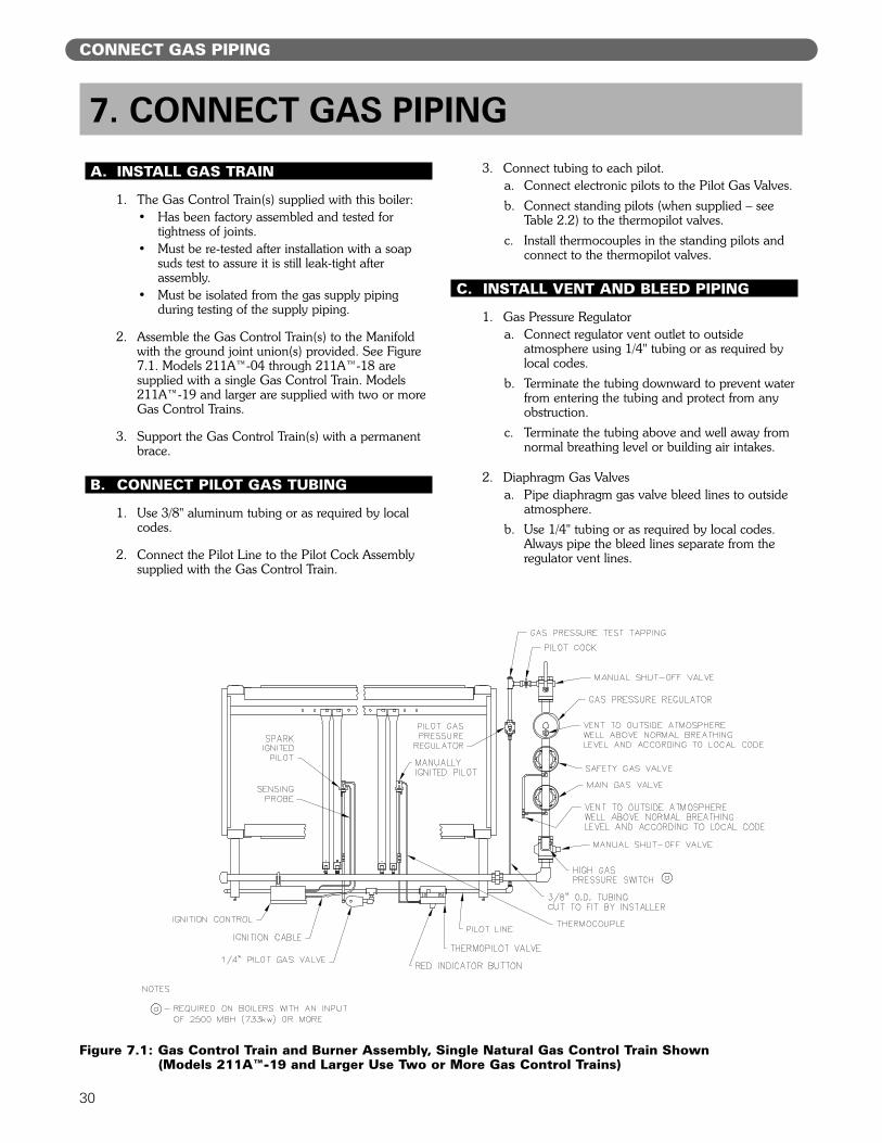
A. INSTALL GAS TRAIN
1. The Gas Control Train(s) supplied with this boiler:• Has been factory assembled and tested for
tightness of joints.• Must be re-tested after installation with a soap
suds test to assure it is still leak-tight afterassembly.
• Must be isolated from the gas supply pipingduring testing of the supply piping.
2. Assemble the Gas Control Train(s) to the Manifoldwith the ground joint union(s) provided. See Figure7.1. Models 211A™-04 through 211A™-18 aresupplied with a single Gas Control Train. Models211A™-19 and larger are supplied with two or moreGas Control Trains.
3. Support the Gas Control Train(s) with a permanentbrace.
B. CONNECT PILOT GAS TUBING
1. Use 3/8" aluminum tubing or as required by localcodes.
2. Connect the Pilot Line to the Pilot Cock Assemblysupplied with the Gas Control Train.
3. Connect tubing to each pilot.a. Connect electronic pilots to the Pilot Gas Valves.
b. Connect standing pilots (when supplied – seeTable 2.2) to the thermopilot valves.
c. Install thermocouples in the standing pilots andconnect to the thermopilot valves.
C. INSTALL VENT AND BLEED PIPING
1. Gas Pressure Regulatora. Connect regulator vent outlet to outside
atmosphere using 1/4" tubing or as required bylocal codes.
b. Terminate the tubing downward to prevent waterfrom entering the tubing and protect from anyobstruction.
c. Terminate the tubing above and well away fromnormal breathing level or building air intakes.
2. Diaphragm Gas Valvesa. Pipe diaphragm gas valve bleed lines to outside
atmosphere.
b. Use 1/4" tubing or as required by local codes.Always pipe the bleed lines separate from theregulator vent lines.
7. CONNECT GAS PIPING
Figure 7.1: Gas Control Train and Burner Assembly, Single Natural Gas Control Train Shown(Models 211A™-19 and Larger Use Two or More Gas Control Trains)
31
CONNECT GAS PIPING
c. When piping bleed lines to outside, terminate thetubing downward to prevent water from enteringthe tubing, and protect the tubing terminationfrom any obstruction. Terminate the tubingabove and well away from normal breathinglevel or building air intakes.
D. INSTALL GAS SUPPLY PIPING
1. Size the piping as required by the National Fuel GasCode, ANSI Z223.1/NFPA 54 and/or CAN/CGAB149 Installation Codes or as required by localcodes.a. Use Table 7.1 for sizing of natural gas for a
system pressure drop of 0.3 inch water column (75 Pa).
2. The standard gas train is designed for a maximumpressure of 1/2 psig (14 inches water column/3.5 kPa).Make sure the system regulator will not allow a higherpressure to the Gas Control Train under anyconditions.
3. The minimum gas supply pressure is listed on theBoiler Rating Label. Make sure the system regulatorand the piping are sized and adjusted properly toprovide this pressure under all conditions.
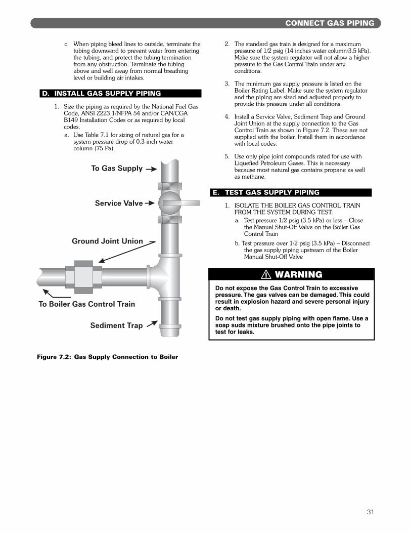
4. Install a Service Valve, Sediment Trap and GroundJoint Union at the supply connection to the GasControl Train as shown in Figure 7.2. These are notsupplied with the boiler. Install them in accordancewith local codes.
5. Use only pipe joint compounds rated for use withLiquefied Petroleum Gases. This is necessarybecause most natural gas contains propane as wellas methane.
E. TEST GAS SUPPLY PIPING
1. ISOLATE THE BOILER GAS CONTROL TRAINFROM THE SYSTEM DURING TEST:a. Test pressure 1/2 psig (3.5 kPa) or less – Close
the Manual Shut-Off Valve on the Boiler GasControl Train
b. Test pressure over 1/2 psig (3.5 kPa) – Disconnectthe gas supply piping upstream of the BoilerManual Shut-Off Valve
Do not expose the Gas Control Train to excessivepressure. The gas valves can be damaged. This couldresult in explosion hazard and severe personal injuryor death.
Do not test gas supply piping with open flame. Use asoap suds mixture brushed onto the pipe joints totest for leaks.
Figure 7.2: Gas Supply Connection to Boiler
⚠ WARNING
32
CONNECT GAS PIPING
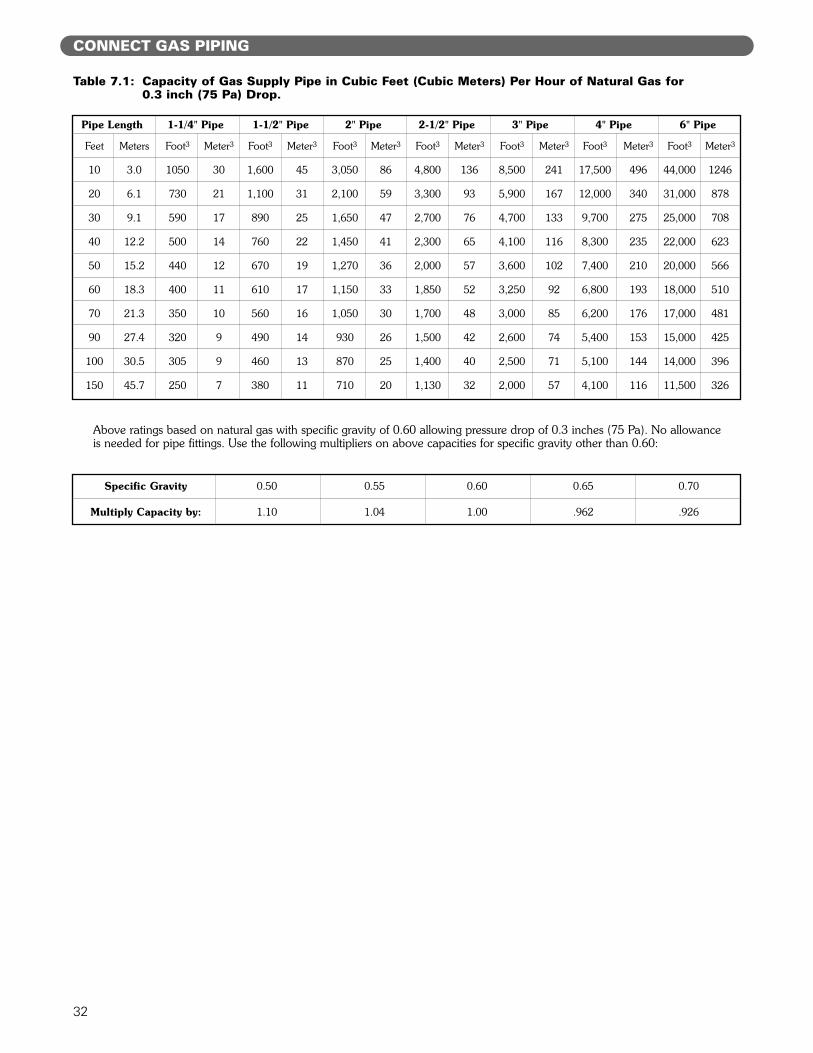
Table 7.1: Capacity of Gas Supply Pipe in Cubic Feet (Cubic Meters) Per Hour of Natural Gas for0.3 inch (75 Pa) Drop.
Above ratings based on natural gas with specific gravity of 0.60 allowing pressure drop of 0.3 inches (75 Pa). No allowanceis needed for pipe fittings. Use the following multipliers on above capacities for specific gravity other than 0.60:
Specific Gravity 0.50 0.55 0.60 0.65 0.70
Multiply Capacity by: 1.10 1.04 1.00 .962 .926
Pipe Length 1-1/4" Pipe 1-1/2" Pipe 2" Pipe 2-1/2" Pipe 3" Pipe 4" Pipe 6" Pipe
Feet Meters Foot3 Meter3 Foot3 Meter3 Foot3 Meter3 Foot3 Meter3 Foot3 Meter3 Foot3 Meter3 Foot3 Meter3
10 3.0 1050 30 1,600 45 3,050 86 4,800 136 8,500 241 17,500 496 44,000 1246
20 6.1 730 21 1,100 31 2,100 59 3,300 93 5,900 167 12,000 340 31,000 878
30 9.1 590 17 890 25 1,650 47 2,700 76 4,700 133 9,700 275 25,000 708
40 12.2 500 14 760 22 1,450 41 2,300 65 4,100 116 8,300 235 22,000 623
50 15.2 440 12 670 19 1,270 36 2,000 57 3,600 102 7,400 210 20,000 566
60 18.3 400 11 610 17 1,150 33 1,850 52 3,250 92 6,800 193 18,000 510
70 21.3 350 10 560 16 1,050 30 1,700 48 3,000 85 6,200 176 17,000 481
90 27.4 320 9 490 14 930 26 1,500 42 2,600 74 5,400 153 15,000 425
100 30.5 305 9 460 13 870 25 1,400 40 2,500 71 5,100 144 14,000 396
150 45.7 250 7 380 11 710 20 1,130 32 2,000 57 4,100 116 11,500 326

33
INSTALL CONTROLS AND TRIM
A. INSTALL SAFETY VALVE(S)
1. Pipe the pop safety valve(s) in the 3" tappingslocated on the right or left end sections. Make surethe relief valve sizing meets local code requirements.
B. INSTALL BLOWDOWN VALVES
1. Install a 1-1/2" full port ball valve in each of thetappings provided at the lower back of the endsections. See Figure 8.1.
2. Pipe the valve discharge to a floor drain if available orapply a nipple and cap to close off when not in use.
C. INSTALL LOW WATER CUT-OFF(S)
1. Mount the float type low water cut-off and gaugeglass in the tappings provided in the front of eitherend section.
2. Do not apply piping which would raise or lower thelocation of the cut-off relative to the tappings in theboiler. Raising the water level over the design heightwill cause water carryover to the system.
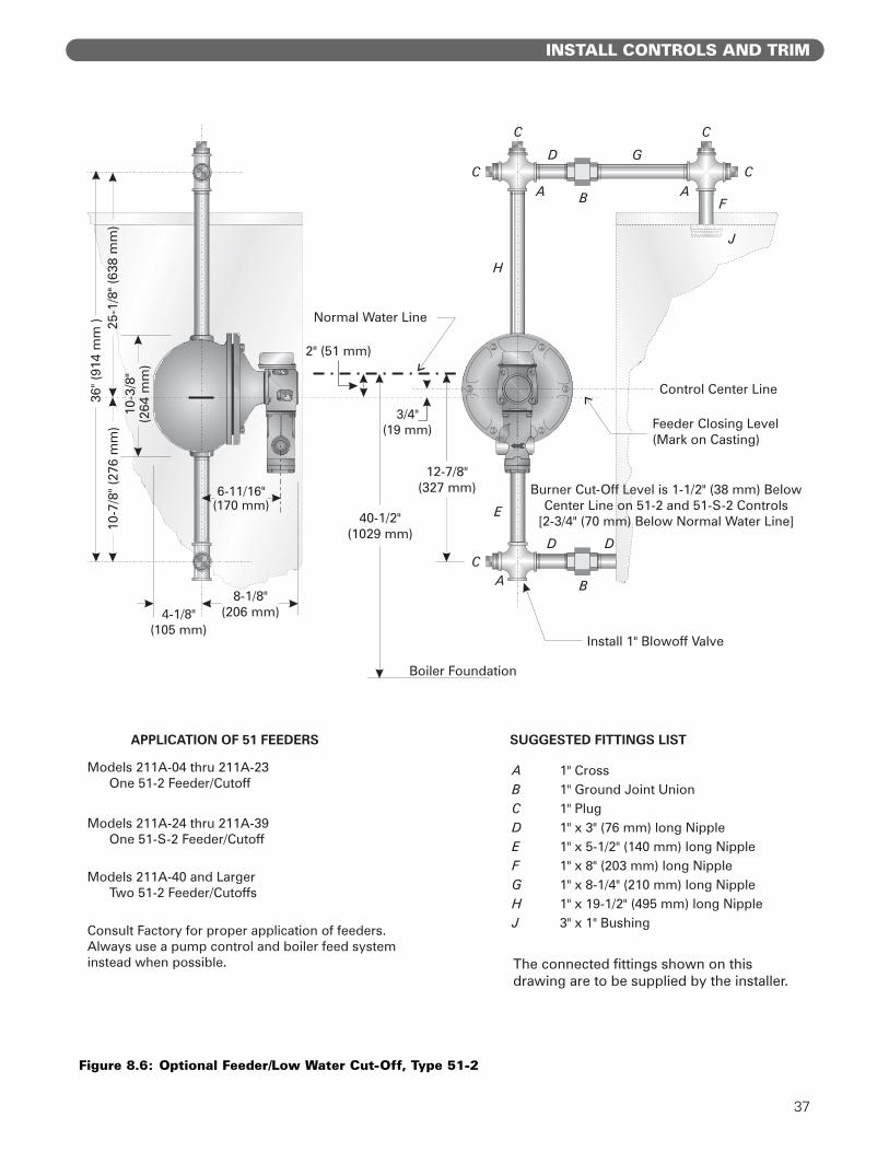
3. For correct location of typical low water cut-off/feederor low water cut-off/pump control, see Figures 8.3through 8.6.
4. Mount the probe type low water cut-off supplied withthe boiler. The end sections have 3/4" tappings in thefront for mounting the probe low water cut-offauxiliary control. See Figure 3.3.a. The standard probe control is Hydrolevel Model
650P. This control is automatic reset type.
b. When a manual reset control is required, the boilercan be supplied with Hydrolevel Model 550P.
5. Provide each float low water cut-off with a blowdownvalve. Pipe the blowdown away from traffic to a floordrain if available. The blowdown valve is required forproper maintenance of the control.
6. Maintain a height of 40-1/2" (1029 mm) from boilerfoundation to the normal water level.
7. When using multiple float type Controls: Always pipethe controls off of the same tappings to the boiler.Do not mount on different ends of the boiler or indifferent tappings. This can cause erratic operationand nuisance problems with the controls.
D. INSTALL PRESSURE CONTROLS
1. Pipe the Steam Pressure Gauge and Boiler Limit andOperating Pressure Controls as shown in Figure 8.2.Connect the control assembly to the 1/2" tapping onthe right end of the boiler.
8. INSTALL CONTROLS AND TRIM
Pipe the discharge of the Safety Relief Valve(s) awayfrom any traffic area, preferably to a floor drain. Thisis necessary to prevent injury should the valvedischarge.
Pipe the discharge full size of valve outlet.
Make sure that the gas ignition system components,electrical controls, junction boxes and electricalpanels are protected from water (dripping, spraying,rain, etc.) during boiler operation and service(circulator or pump servicing, control replacementsor other).Figure 8.1: Blowdown Valve Piping
⚠ CAUTION
⚠ CAUTION

34
INSTALL CONTROLS AND TRIM
Figure 8.2: Pressure Control Piping (Fittings Included with Boiler)
35
INSTALL CONTROLS AND TRIM
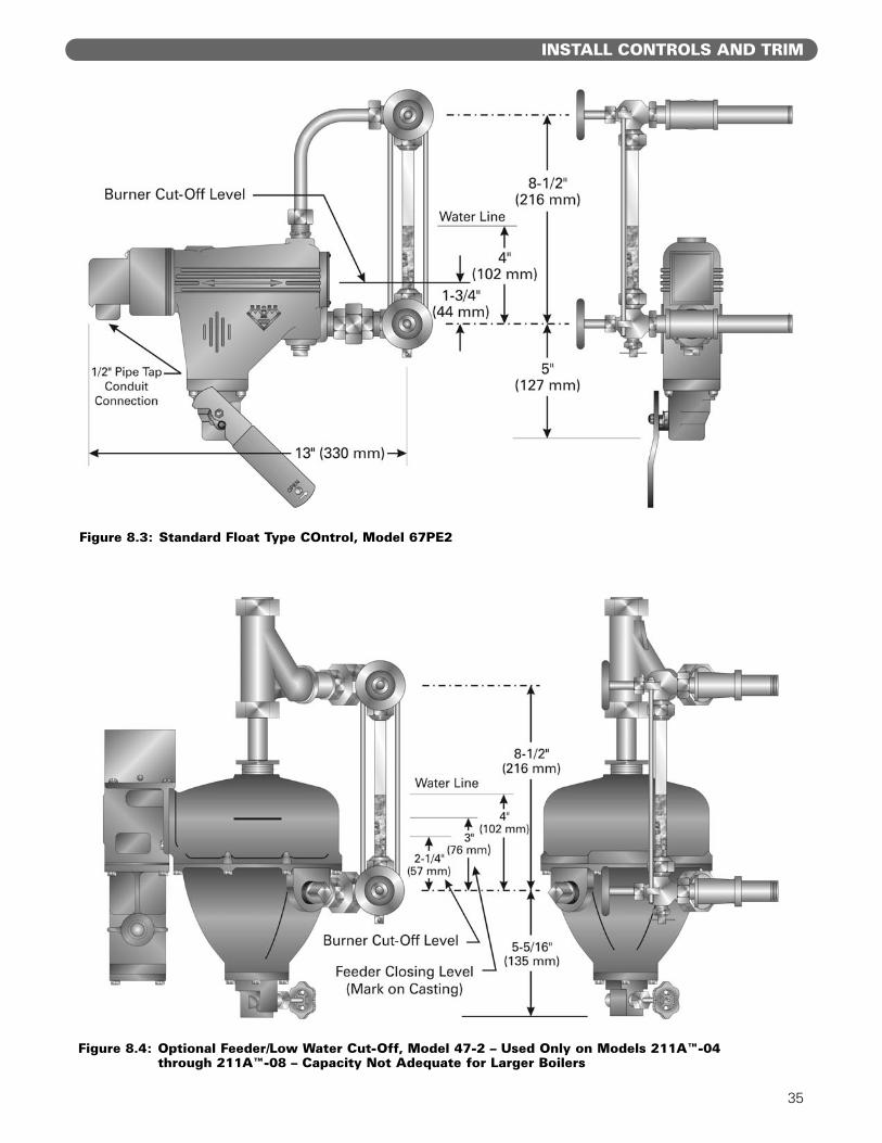
Figure 8.4: Optional Feeder/Low Water Cut-Off, Model 47-2 – Used Only on Models 211A™-04through 211A™-08 – Capacity Not Adequate for Larger Boilers
Figure 8.3: Standard Float Type COntrol, Model 67PE2

36
INSTALL CONTROLS AND TRIM
Figure 8.5: Optional Float Type Pump Control/Low Water Cut-Off, Model 157
37
INSTALL CONTROLS AND TRIM
Figure 8.6: Optional Feeder/Low Water Cut-Off, Type 51-2
APPLICATION OF 51 FEEDERS
Models 211A-24 thru 211A-39One 51-S-2 Feeder/Cutoff
Models 211A-40 and LargerTwo 51-2 Feeder/Cutoffs
Consult Factory for proper application of feeders.Always use a pump control and boiler feed systeminstead when possible.
Normal Water Line
Feeder Closing Level(Mark on Casting)
2" (51 mm)
3/4"19 mm)(
12-7/8"327 mm)(6-11/16"
170 mm( )
25-1
/8" (
638
mm
)
Boiler Foundation
10-3
/8"
264
mm
)(
10-7
/8" (
276
mm
)36
" (91
4 m
m )
4-1/8"105 mm( )
8-1/8"206 mm)(
Install 1" Blowoff Valve
Burner Cut-Off Level is ( ) BelowCenter Line on 51-2 and 51-S-2 Controls
[ ( ) Below Normal Water Line]
1-1/2" 38 mm
2-3/4" 70 mm
Control Center Line
The connected fittings shown on thisdrawing are to be supplied by the installer.
J
FA
A
AB
B
D
D D
C
C C
C
CG
H
E
Models 211A-04 thru 211A-23One 51-2 Feeder/Cutoff
SUGGESTED FITTINGS LIST
ABCDEFGHJ
1" Cross1" Ground Joint Union1" Plug1" x ( ) long Nipple1" x ( ) long Nipple1" x ( ) long Nipple1" x ( ) long Nipple1" x ( ) long Nipple3" x 1" Bushing
3" 76 mm5-1/2" 140 mm8" 203 mm8-1/4" 210 mm19-1/2" 495 mm
40-1/2"(1029 mm)
38
WIRE THE BOILER
A. CONNECT SUPPLY WIRING
1. All wiring must be done in accordance with localcodes, the National Electrical Code ANSI/NFPA70and/or the Canadian Electrical Code Part I, CSAC22.1, Electrical Code and other controllingagencies or governing bodies.
2. Use #14 gauge or heavier wire for supply wiring.Protect the circuit with a fused disconnect switch (byothers) and a grounded neutral.
3. Mount an electrical junction box on the boiler FrontPanel for connection of supply wiring anddistribution to the boiler controls. See Figure 9.1.
B. PREPARE REMAINING CONTROLS
1. Mount the control transformer on the junction box asshown in Figure 9.1.
2. Mount a junction box near each Gas Control Trainfor connection of conduit and wiring distribution tothe gas train components.
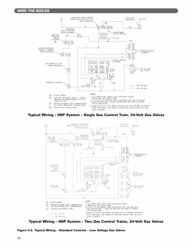
C. INSTALL CONTROL WIRING
1. Wire the boiler according to the wiring diagramsupplied with the boiler (in the Control Envelope).Figure 9.1 is a typical layout of the components onthe boiler. Figures 9.2 and 9.3 are examples ofstandard wiring systems. Use these drawings forgeneral reference only.
2. Low Energy Safety Control wiring must follow thecontour of the boiler. Some local codes may requirethat all wiring, even low voltage, be routed inconduit.
3. Install all line voltage wiring in conduit.
4. Do not install single pole switches, including safetycontrols, in a grounded line.
9. WIRE THE BOILER
The boiler/burner must be electrically grounded inaccordance with the requirements of the authorityhaving jurisdiction, or in the absence of suchrequirements, with the current edition of the NationalElectrical Code, ANSI/NFPA Number 70 and/or theCanadian Electrical Code Part I, CSA C22.1, ElectricalCode.
Label all wires prior to disconnection when servicingcontrols. Wiring errors can cause improper anddangerous operation. Verify proper operation afterservicing.
Identifier tous les câbles avant de les débrancher aumoment d’effectuer l’entretien des commandes. Deserreurs dans le raccordement des câblesd’alimentation peuvent causer un fonctionnementinadéquat et dangereux. Vérifier le bonfonctionnement après les travaux d’entretien.
⚠ CAUTION
⚠ NOTICE
⚠ AVERTISSEMENT

39
Figure 9.1: Typical Control Layout and Wiring
WIRE THE BOILER
40
WIRE THE BOILER
Figure 9.2: Typical Wiring – Standard Controls – Low Voltage Gas Valves
Typical Wiring - HSP System - Single Gas Control Train, 24-Volt Gas Valves
Typical Wiring - HSP System - Two Gas Control Trains, 24-Volt Gas Valves
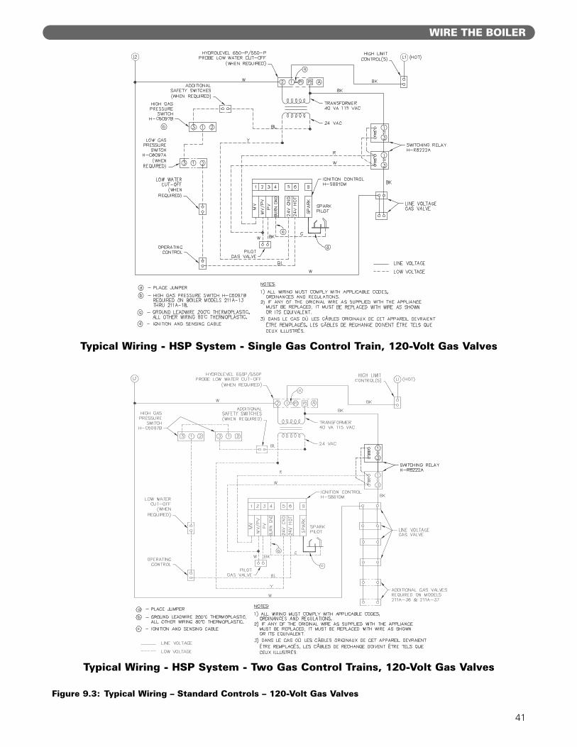
41
WIRE THE BOILER
Figure 9.3: Typical Wiring – Standard Controls – 120-Volt Gas Valves
Typical Wiring - HSP System - Single Gas Control Train, 120-Volt Gas Valves
Typical Wiring - HSP System - Two Gas Control Trains, 120-Volt Gas Valves

STARTING THE BOILER
A. CHECK THE PIPING1. Water and Steam Piping
a. The Boiler must have been hydrostatically tested.b. Check the attached piping for joint tightness. c. Continue monitoring as you proceed through
start up.
2. Gas Pipinga. Make sure the gas system piping and the
connections to the boiler Gas Control Train(s)have been leak tested.
b. After the boiler is in operation, check thetightness of all joints in the boiler gas piping witha soap suds solution.
c. Purge the gas piping of all air up to the boilerGas Control Train.
B. FILL THE BOILER1. Fill the boiler to the normal water line.
a. Gravity Systems and Pumped Return withCondensate Units-Fill to 40-1/2" (103 cm) abovethe boiler foundation (center of gauge glass).
b. Pumped Return with Boiler Feed Unit–Fill theboiler using the boiler feed unit. Fill level willdepend on the control being used, but should be40-1/2" (103 cm) above the boiler foundation(just below center of gauge glass) when thepump stops.
C. STUDY LIGHTING INSTRUCTIONS1. Before starting the boiler, study the Lighting
Instructions supplied with the boiler.
D. RUN PILOT CHECK-OUT1. Shut off all electrical power to the boiler.
2. Close Main and Pilot gas shut-off valves. Wait forfive (5) minutes.
3. Set the Operating and Limit Pressure Controls tominimum setting so they will not call for heat.
4. Perform Pilot Check:a. Turn main electric disconnect switch to the ON
position.b. Turn up the settings on the Operating and Limit
Pressure Controls so they will call for heat.c. Check for a continuous spark at the electronic
spark-ignited pilot(s).d. Electronic spark-ignited pilot systems–The control
will spark for 15 seconds (trial for ignition), thenshut down for a 5 to 6 minute wait period beforeattempting another ignition.
e. Electronic standing pilot systems–Within 15seconds the control will click, indicating a safetylockout.
f. Turn down the Operating Pressure Control tostop the call for heat.
g. Wait 60 seconds to allow the control to resetbefore proceeding with the next step.
5. Light Manual Pilotsa. Follow the procedure in the Lighting Instructions
to manually light any standing pilots.
6. Electronic Spark-Ignited Pilot Ignition Checka. Turn up the Operating Pressure Control for a call
for heat.b. The electronic spark-ignited pilot(s) should ignite.c. Turn down the Operating Pressure Control to
stop the call for heat.d. The spark-ignited pilot(s) should shut off.
7. Check Main Burner Ignitiona. With the Operating Pressure Control turned
down, open the main gas shut-off valve(s).b. Turn up the Operating Pressure Control for a call
for heat.c. The electronic spark-ignited pilot(s) should ignite.d. The main gas valves will then open and the main
burners should ignite.e. Turn down the Operating Pressure Control to
stop the call for heat.f. The electronic spark-ignited pilot(s) and main
burners should shut off.
E. CHECK MAIN BURNER SYSTEM1. Remove the pressure test plug at the Main gas shut-
off valve. Attach a U-tube manometer.
2. Restart the boiler by turning up the OperatingPressure Control for a call for heat.
3. Leak test all gas train joints with a soap sudssolution.
4. Check the gas pressure at the entrance to the GasControl train. a. The pressure reading under flow should be
between 5 and 14 inches water column (1.7 and3.5 kPa).
b. If the pressure to the Gas Control Train exceeds14 inches (3.5 kPa) under any conditions, thesystem must be provided with a lockup type gaspressure regulator to provide 14 inches (3.5 kPa)maximum.
5. Check the Manifold gas pressure.a. Remove the 1/8" pipe plug from the manifold gas
pressure tapping.b. Attach a U-tube manometer.c. Adjust the Main Gas Pressure Regulator to obtain
3.5 inches water column (.9 kPa) on Natural Gas10 inches water column (2.5 kPa) on Propane(LP) Gas.
d. NOTE: If the pressure is adjusted to set thenameplate input to the boiler, do not set it morethan 0.3 inches (75 Pa) plus or minus from thespecified settings. If more adjustment to the rateis needed, it must be done by changing theburner gas orifices.
10. STARTING THE BOILER
42

STARTING THE BOILER
e. The Minimum input rate listed on the nameplateapplies to boilers with staged firing rate. Thisminimum rate is not adjustable. It is controlledby an orifice in the gas train.
6. Check the burner input by reading the gas meter.a. Each of the burners is rated at 105,000 Btu/hr
(30.8 kW) for Natural Gas with a 0.60 specificgravity.
b. Each of the burners is rated at 102,500 Btu/hr(30 kW) for Propane (LP) Gas with a 1.56specific gravity.
c. (U.S.) Determine the input by multiplying “F” –Meter Reading (Cubic Feet of Gas) times “H” –Heating Value of Gas (Btu per Cubic Foot) times3600. Divide by “T” – the time in seconds at themeter reading.
(Metric) Determine the input by multiplying “F”–Meter Reading (Cubic Meters of Gas) times “H” –Heating Value of Gas (Joules per Cubic Meter).Divide by “T” – the time in seconds of the meterreading.
d. Note: If the meter is not automatically correctedfor temperature and pressure, the meter readingmust be corrected to actual conditions during therate test.
7. Adjustment of Primary Aira. A bag of air adjustment screws is provided with
the boiler, attached to one of the burners withpilot bracket.
b. Primary air adjustment is not normally required. c. If primary air adjustment is needed, insert the
self-tapping screws into the holes located on thetop front of the burners.
d. Turn the screws in all the way until yellow flametips appear. Turn the screws back out until theyellow tips disappear.
F. CHECK BOILER CONTROLS
1. Limit and Operating Pressure Controlsa. Lower the setting of each control until the
burners shut down.
2. Low Water Cut-offsa. Lower the water level in the boiler to below the
control cut-off level. The burners should shut down.
3. Main Burner Shut-Off Valve(s)a. Close Main Burner Shut-Off Valve(s).b. The burners should shut down.
4. Check all controls to make sure they function correctly.
5. After all controls have been proven, set the Operatingand Limit Pressure Controls to the pressures desired.
G. CLEAN THE BOILER
1. Clean the boiler as described below no later thanone week after the initial start-up. Cleaning will bemore effective if the boiler operates a day or two toloosen sediment and impurities in the system.
2. The boiler must be cleaned to remove anyaccumulation of oil, grease, sludge, etc. that may be
in the system. These substances can cause foamingand surging of the boiler water, producing anunstable water line and water carryover to the system.
3. The piping for a skim valve must be done as shownin Section 5, “Pipe the Boiler,” of this manual, withthe skim valve mounted off of one of the end riserconnections.
4. Connect a 2 inch drain line off of the skim valve, runto a point of safe discharge.
5. Close all valves to the system. Provide a means ofcontinuous fresh water to the boiler for the cleaningprocess.
6. Use common washing soda (such as Arm andHammer Super Washing Soda). Mix the soda withwater in a 10 quart (9.5 liter) pail and pour into theboiler through the safety valve tapping. Use aproportion of one (1) pound (.5 kg) of washing sodafor each 800 square feet (74 m²) EDR net boiler rating.
7. Open the skim valve. Fill the boiler until water beginsto flow out the valve.
8. Turn burners on and allow the boiler water to heatup to just below steaming [180 to 200ºF (82 to93ºC)]. Cycle the burners to maintain temperatureduring skimming. Do not allow the boiler to steam.Steaming mixes up the contaminants in the waterinstead of floating them at the surface.
9. Open the make-up water valve to continuously feedwater to the boiler. Allow water to flow out of theskim tapping.
10. Continue skimming the boiler until the water flowingfrom the skim tapping flows clear. This will takesome time, possibly several hours for a dirty system.
11. After skimming is complete, close the skim valve andturn off the boiler.
12. Close the make-up water valve and open the boilerblowdown valves.
13. Drain the boiler completely. Then refill and drainagain one or two times to make sure all of the sodahas been washed out.
14. Restore piping to normal. Pipe a nipple and cap inthe skim valve.
15. Note: If the gauge glass becomes dirty again, thisindicates more contaminants have worked loose inthe system. Repeat the cleaning and skimmingprocess as needed to clean the system.
Rate, Btu/Hr = F x H x 3600T
Rate, Watts = F x HT
Cleaning the boiler requires the use of very hot waterand corrosive chemicals. Use care when handling toprevent injury.
43
Do not leave the boiler unattended while firing.
Take great care not to allow the water level to dropbelow the bottom of the gauge glass or to allow freshwater make-up to flow in too fast. This will avoid thepossibility of causing the boiler sections to fracture.
⚠ WARNING
⚠ CAUTION

44
LIGHTING INSTRUCTIONS – TYPICAL
A. TO LIGHT THE BOILER
1. These instructions apply only to typical standardcontrol systems (HSP System only). Use the LightingInstructions supplied with the boiler to be sure theyapply to the actual control system used.
2. Set Operating Control to lowest position.
3. Open main line power disconnect switch to boiler.
4. Close Main and Pilot gas shut-off valves.
5. Wait at least five (5) minutes.
6. With Main gas shut-off valve(s) closed, open Pilotgas shut-off valve.
7. Light standing (manual) pilots by depressing the redindicator button on the thermopilot valve. Manuallylight the pilot and hold the red button long enoughfor the thermocouple to heat up.
8. Open Main Gas shut-off valve.
9. Set Operating Control to desired setting.
10. Close main line power disconnect switch to boiler.
11. If all limit switches are closed, the spark pilot(s) willlight, main gas valves will open and main burnerswill light.
12. The burners will continue to fire until the OperatingControl is satisfied.
B. TO SHUT DOWN THE BOILER
1. Open main line power disconnect switch to boiler.
2. Close Main and Pilot gas shut-off valves.
C. PILOT FLAME FAILURE
1. If flame signal is lost at pilot, the ignition control willshut off the main gas valves and start sparking within0.8 seconds.
2. The control will continue to spark for 15 seconds.
3. If a flame is not sensed, the control will shut downthe pilot gas valve and wait 5 to 6 minutes.
4. It will then start sparking and open the pilot gasvalve for another 15-second ignition trial.
5. The control will continue this sequence indefinitely.
6. Refer to Control Envelope supplied with the boilerfor the specific system used.
7. Should a flame failure occur, causing a shut down ofthe main burners, turn off all electric power to theboiler and close Main and Pilot manual shut-offvalves. Call a qualified service technician to inspectthe boiler and correct the problem.
11. LIGHTING INSTRUCTIONS – TYPICAL
Figure 11.1: Typical Gas Control Train and Base - Single Gas Control Train - Standard Controls
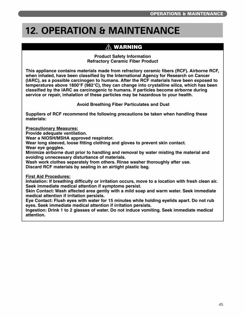
45
OPERATIONS & MAINTENANCE
12. OPERATION & MAINTENANCE
Product Safety InformationRefractory Ceramic Fiber Product
This appliance contains materials made from refractory ceramic fibers (RCF). Airborne RCF,when inhaled, have been classified by the International Agency for Research on Cancer(IARC), as a possible carcinogen to humans. After the RCF materials have been exposed totemperatures above 1800°F (982°C), they can change into crystalline silica, which has beenclassified by the IARC as carcinogenic to humans. If particles become airborne duringservice or repair, inhalation of these particles may be hazardous to your health.
Avoid Breathing Fiber Particulates and Dust
Suppliers of RCF recommend the following precautions be taken when handling thesematerials:
Precautionary Measures:Provide adequate ventilation.Wear a NIOSH/MSHA approved respirator.Wear long sleeved, loose fitting clothing and gloves to prevent skin contact.Wear eye goggles.Minimize airborne dust prior to handling and removal by water misting the material andavoiding unnecessary disturbance of materials. Wash work clothes separately from others. Rinse washer thoroughly after use.Discard RCF materials by sealing in an airtight plastic bag.
First Aid Procedures:Inhalation: If breathing difficulty or irritation occurs, move to a location with fresh clean air.Seek immediate medical attention if symptoms persist.Skin Contact: Wash affected area gently with a mild soap and warm water. Seek immediatemedical attention if irritation persists.Eye Contact: Flush eyes with water for 15 minutes while holding eyelids apart. Do not rubeyes. Seek immediate medical attention if irritation persists.Ingestion: Drink 1 to 2 glasses of water. Do not induce vomiting. Seek immediate medicalattention.
⚠ WARNING

46
OPERATIONS & MAINTENANCE
A. PLACING BOILER IN OPERATION
1. Start up the boiler per the Lighting Instructionsshipped with the boiler.
2. Prove the correct operation of all controls on theboiler as outlined below.
3. Check the operation of the ignition and flameproving controls:a. Electronic Spark-Ignited Pilot System (S8610M
Control)
• With the boiler operating, close the Pilotmanual shut-off valve.
• The ignition control should close the maingas valves within 1 second.
• The control will spark and attempt to relightthe pilot burner.
• After 15 seconds, the control will shut downand wait 5 to 6 minutes for another ignitiontrial.
• Open the Pilot manual shut-off valve and re-start the boiler per the Lighting Instructions.(Standing pilots will have to be manually re-lit per the Lighting Instructions.)
b. Electronic Standing Pilot System
• With the boiler operating, close the Pilotmanual shut-off valve.
• The ignition control should close the maingas valves within 3 seconds after the pilotgoes out.
• After 15 seconds, the control will lock out.
• Open the Pilot manual gas shut-off valve andre-start the boiler per the LightingInstructions. (Standing pilots will have to bemanually re-lit per the Lighting Instructions.)
4. Check the manifold gas pressure and use a soap sudsmixture to check the gas tightness of all gas joints.
5. Test the limit and operating controls to assure theyare operating correctly.
6. Inspect and test all low water cut-offs. (Float typecontrols must be flushed (blown down) weekly toremove any sediment from the float chamber.)
7. Test the pop safety relief valve(s) using the proceduregiven by the valve manufacturer on the valve tag.
8. Visually inspect the burner and pilot flames.a. See Figure 12.1.
b. The flame inner cone should be about 1-1/2"(4 cm) high and should have a very sharp, bluecolor characteristic.
c. Poor flame conditions can be caused by dirtyburners, obstructed orifices, or incorrect gaspressure.
Figure 12.1: Pilot and Burner Flames
Do not store or allow combustible or flammablematerials near the boiler. Substantial fire or explosionhazard could result, causing risk of personal injury,death or property damage.
Do not use this boiler if any part of it has been underwater. Immediately call a qualified service technicianto inspect the boiler. Any part of the control system,any gas control or any burner or gas componentwhich has been under water must be replaced.
Should overheating occur or the fuel supply fail toshut off: Shut off the fuel supply at a locationexternal to the boiler. Do not turn off or disconnectthe electrical supply to the pump. Immediately call aqualified service technician to inspect the boiler fordamage and defective components.
⚠ WARNING

47
OPERATIONS & MAINTENANCE
B. TO SHUT DOWN THE BOILER
1. Open main line power disconnect switch to boiler.
2. Close Main and Pilot gas shut-off valves.
3. To take boiler out of service if the boiler and systemare not to be used when temperatures are belowfreezing:a. Drain the boiler and system completely and shut
off make-up water supply.
b. Open main line power disconnect switch toboiler. Remove the fuses or secure the switch sothat the power cannot be turned on accidentally.
c. Do not use ethylene glycol antifreeze in a steamboiler or system.
d. Be certain that the boiler and system are refilledbefore returning to service. Follow theInstructions in this manual and the LightingInstructions to operate.
C. ANNUAL MAINTENANCE
1. Before the start of each heating season, inspectand make all necessary adjustments to insure properboiler operation. Use the maintenance andinspection procedures following.
2. Inspect the Venting Systema. Check the chimney or vent to make sure it is
clean and free from cracks or potential leaks.
b. All joints must be tight and sealed.
c. The vent connector must extend into, but notbeyond, the inside edge of the chimney or vent.
3. Inspect the Boiler Areaa. The boiler area must be clean and free from
combustible materials, gasoline or any otherflammable liquids or vapors.
b. The combustion air openings and the areaaround the boiler must be unobstructed.
4. Inspect boiler flueways and burners for cleanliness. Ifcleaning is required, use the following procedure.a. Turn off all electrical power to the boiler.
b. Remove top jacket panels, draft hood and fluecollector.
c. Remove side cleanout panels.
d. Brush the boiler tube spaces both horizontally(through cleanout openings on ends) andvertically (from top of boiler).
e. Replace the flue collector, draft hood, jacket andcleanout panels using the procedures given inthis manual.
f. Remove the burners and brush the gas portslightly with a soft bristle brush.
5. Inspect the boiler base and insulation.
6. Inspect the boiler and piping for signs of leaks.Check to see if there are signs of heavy make-upwater addition to the system.
7. When placing boiler into operation, follow LightingInstructions shipped with the boiler and theinstructions in this Chapter.
8. Test the operation of all limit controls, float controls,and ignition components as described in Part A,Placing Boiler in Operation, of this Chapter.
D. MONTHLY MAINTENANCE
1. Inspect the burner and pilot flames as for the annualinspection.
2. Inspect the boiler and system for any signs ofleakage or excessive make-up water usage.
3. Inspect and check the operation of the ventingsystem.
E. WEEKLY MAINTENANCE
1. Blow down the float type low water cut-offs and testfor correct operation.
F. DAILY MAINTENANCE
1. Inspect the boiler area to make sure the area is freefrom combustible or flammable materials and thatthere are no obstructions to the flow of air to theboiler or combustion air openings to the room.
2. Make sure there are no signs of abnormal operation,such as overfilling or leakage.
Be very careful when adding water to a hot boiler.Add very slowly or, if possible, allow the boiler tocool naturally before adding water.
If an excessive loss of water occurs, check for a leakin the piping and correct the problem. Excessivemake-up water will cause corrosion and damage tothe boiler.
Before servicing the boiler:
• Turn off all electrical power to the boiler.
• Close the Gas Service Valve.
• Allow the boiler to cool if it has been operating.
• Label all wires prior to disconnection whenservicing controls. Wiring errors can causeimproper and dangerous operation. Verify properoperation after servicing.
⚠ CAUTION
⚠ CAUTION

48
TROUBLESHOOTING – SERVICE TIPS
13. TROUBLESHOOTING – SERVICE TIPSProblem Possible Cause Suggested Remedy
Defective Thermocouple Replace
Heavy Draft Blowing across Pilot Redirect Air Movement or Eliminate
Plugged Pilot Orifice Replace Orifice
Pilot Outage Check Manual Pilot ValveCheck Main Gas Shut-Off ValveNo GasCheck Manual Meter ValveConsult Gas Company
Defective Thermopilot Valve Replace
Defective Ignition Control Replace
No PowerCheck Power Source with MeterCheck Fuses
Defective Gas Valve Replace
Defective Thermocouple Replace
Low Water Level in Boiler Check for LeaksMain Gas Valve Will Not Open or System Causing Low Water Cut-off to Function Check Feeder (if Supplied)
(Standard Spark-Ignited Pilot System) Defective Thermopilot Valve Replace
Defective Ignition Control Replace
High Gas Pressure Switch Open Check Switch Setting(if Provided) Check Manifold Gas Pressure
Low Gas Pressure Switch Open Check Switch Setting(if Provided) Check Manifold Gas Pressure
No PowerCheck Power Source with MeterCheck Fuses
Defective Gas Valve Replace
Relay Locked Out on Safety Check for Pilot Outage
Pilot OutRelight Pilot(May have defective pilot valve or relay)
Main Gas Valve Will Not Open Defective Relay Replace
(Electronic Standing Pilot System) Low Water in Boiler Check for Leaksor System Causing Low Water Cut-off to Function Check Feeder (if Supplied)
Defective Thermopilot Valve(s) Replace
Defective Thermocouple(s) Replace
High Gas Pressure Switch Open Check Switch Setting(if Provided) Check Manifold Gas Pressure
Low Gas Pressure Switch Open Check Switch Setting(if Provided) Check Inlet Gas Pressure
Air Adjustment Screws Turned in Too Far Adjust Screws Out
Low Gas Pressure in Manifold Adjust Main Gas Pressure Regulator(Insufficient Air Injection) or Check Line Pressure
Burner Ports Partially Closed (Rust, Dirt, Lint, etc.) Replace Burners or Clean Ports
Burner(s) Burning with Yellow Flame Check Size of Combustion Air Openings to Insufficient Air for Combustion Room, if Undersized, Correct as Required
Check for Negative Pressure in Boiler Room
Oversized Burner Orifice Install Correct Orifice
High Gas Pressure in Manifold Adjust Main Gas Pressure Regulator
Insufficient Draft – Chimney Too Low Increase Height or Add Induced Draft Fan
Insufficient Draft – Chimney Too Small Replace Chimney or Add Induced Draft Fan
Gas Spillage fromInsufficient Draft – Blockage in Chimney or Vent Repair Chimney or Vent
Insufficient Draft – Downdraft Caused by Draft Hood Relief OpeningChimney Location with Respect to Install Chimney CapOther Buildings, Roofs, etc.
Negative Pressure in Boiler Room Remove Exhaust Fan(Due to Exhaust Fan or Duct System) or Isolate Fan From Boiler Room
Insufficient Combustion Air Openings Provide Correctly Sized Combustion andVentilation Air Openings
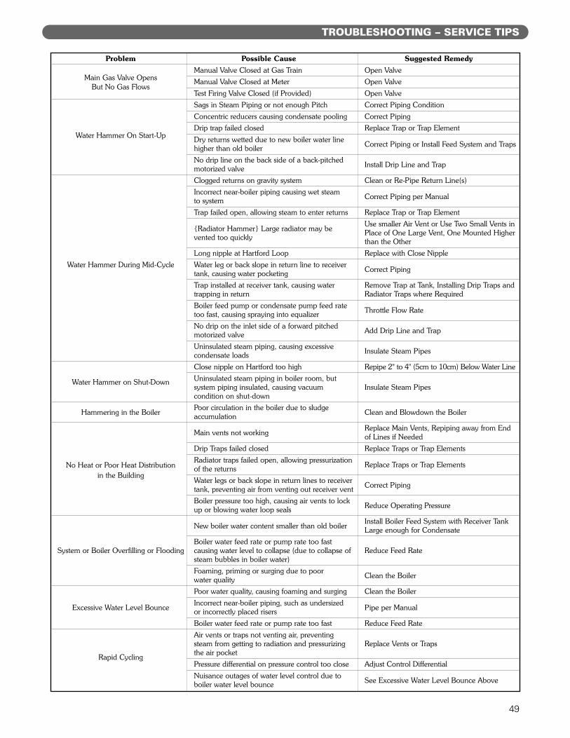
49
TROUBLESHOOTING – SERVICE TIPS
Problem Possible Cause Suggested Remedy
Main Gas Valve OpensManual Valve Closed at Gas Train Open Valve
But No Gas FlowsManual Valve Closed at Meter Open Valve
Test Firing Valve Closed (if Provided) Open Valve
Sags in Steam Piping or not enough Pitch Correct Piping Condition
Concentric reducers causing condensate pooling Correct Piping
Drip trap failed closed Replace Trap or Trap ElementWater Hammer On Start-Up Dry returns wetted due to new boiler water line
Correct Piping or Install Feed System and Trapshigher than old boiler
No drip line on the back side of a back-pitchedInstall Drip Line and Trapmotorized valve
Clogged returns on gravity system Clean or Re-Pipe Return Line(s)
Incorrect near-boiler piping causing wet steam Correct Piping per Manualto system
Trap failed open, allowing steam to enter returns Replace Trap or Trap Element
{Radiator Hammer} Large radiator may beUse smaller Air Vent or Use Two Small Vents in
vented too quicklyPlace of One Large Vent, One Mounted Higherthan the Other
Long nipple at Hartford Loop Replace with Close Nipple
Water Hammer During Mid-Cycle Water leg or back slope in return line to receiverCorrect Pipingtank, causing water pocketing
Trap installed at receiver tank, causing water Remove Trap at Tank, Installing Drip Traps andtrapping in return Radiator Traps where Required
Boiler feed pump or condensate pump feed rateThrottle Flow Ratetoo fast, causing spraying into equalizer
No drip on the inlet side of a forward pitchedAdd Drip Line and Trapmotorized valve
Uninsulated steam piping, causing excessiveInsulate Steam Pipescondensate loads
Close nipple on Hartford too high Repipe 2" to 4" (5cm to 10cm) Below Water Line
Water Hammer on Shut-Down Uninsulated steam piping in boiler room, butsystem piping insulated, causing vacuum Insulate Steam Pipescondition on shut-down
Hammering in the BoilerPoor circulation in the boiler due to sludge
Clean and Blowdown the Boileraccumulation
Main vents not workingReplace Main Vents, Repiping away from End of Lines if Needed
Drip Traps failed closed Replace Traps or Trap Elements
No Heat or Poor Heat DistributionRadiator traps failed open, allowing pressurization
Replace Traps or Trap Elementsof the returnsin the Building
Water legs or back slope in return lines to receiverCorrect Pipingtank, preventing air from venting out receiver vent
Boiler pressure too high, causing air vents to lockReduce Operating Pressureup or blowing water loop seals
New boiler water content smaller than old boilerInstall Boiler Feed System with Receiver TankLarge enough for Condensate
Boiler water feed rate or pump rate too fastSystem or Boiler Overfilling or Flooding causing water level to collapse (due to collapse of Reduce Feed Rate
steam bubbles in boiler water)
Foaming, priming or surging due to poor Clean the Boilerwater quality
Poor water quality, causing foaming and surging Clean the Boiler
Excessive Water Level BounceIncorrect near-boiler piping, such as undersized
Pipe per Manualor incorrectly placed risers
Boiler water feed rate or pump rate too fast Reduce Feed Rate
Air vents or traps not venting air, preventingsteam from getting to radiation and pressurizing Replace Vents or Traps
Rapid Cyclingthe air pocket
Pressure differential on pressure control too close Adjust Control Differential
Nuisance outages of water level control due toSee Excessive Water Level Bounce Aboveboiler water level bounce
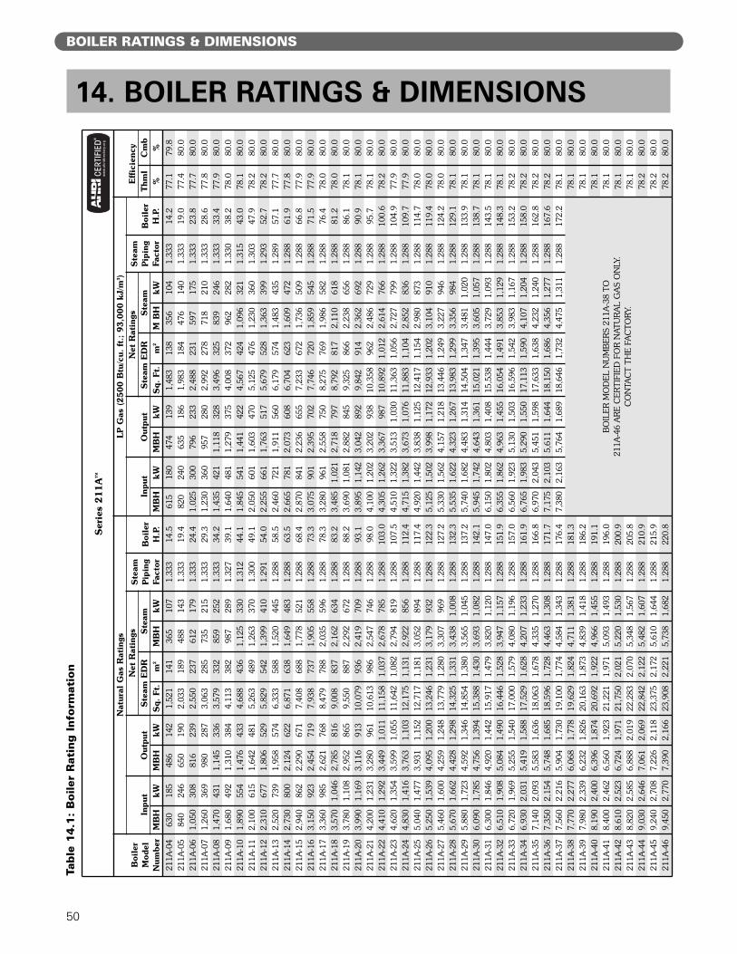
50
BOILER RATINGS & DIMENSIONS
14. BOILER RATINGS & DIMENSIONSTa
ble
14.1
: B
oiler
Rati
ng I
nfo
rmati
on
Ser
ies
211A™
Boi
ler
Mod
el
Num
ber
Nat
ural
Gas
Rat
ings
LP
Gas
(2500 B
tu/c
u. f
t.;
93,0
00 k
J/m
3)
Eff
icie
ncy
Inpu
tO
utpu
tN
et R
atin
gsS
team
Pip
ing
Fact
orB
oile
rH
.P.
Inpu
tO
utpu
tN
et R
atin
gsS
team
Pip
ing
Fact
orB
oile
rH
.P.
Ste
am E
DR
Ste
amS
team
ED
RS
team
Thm
lC
mb
MB
HkW
MB
HkW
Sq.
Ft.
m2
MB
HkW
MB
HkW
MB
HkW
Sq.
Ft.
m2
M B
HkW
%%
211A
-04
630
185
486
142
1,52
114
136
510
71.
333
14.5
615
180
474
139
1,48
313
835
610
41.
333
14.2
77.1
79.8
211A
-05
840
246
650
190
2,03
318
948
814
31.
333
19.4
820
240
635
186
1,98
318
447
614
01.
333
19.0
77.4
80.0
211A
-06
1,05
030
881
623
92,
550
237
612
179
1.33
324
.41,
025
300
796
233
2,48
823
159
717
51.
333
23.8
77.7
80.0
211A
-07
1,26
036
998
028
73,
063
285
735
215
1.33
329
.31,
230
360
957
280
2,99
227
871
821
01.
333
28.6
77.8
80.0
211A
-08
1,47
043
11,
145
336
3,57
933
285
925
21.
333
34.2
1,43
542
11,
118
328
3,49
632
583
924
61.
333
33.4
77.9
80.0
211A
-09
1,68
049
21,
310
384
4,11
338
298
728
91.
327
39.1
1,64
048
11,
279
375
4,00
837
296
228
21.
330
38.2
78.0
80.0
211A
-10
1,89
055
41,
476
433
4,68
843
61,
125
330
1.31
244
.11,
845
541
1,44
142
24,
567
424
1,09
632
11.
315
43.0
78.1
80.0
211A
-11
2,10
061
51,
642
481
5,26
348
91,
263
370
1.30
049
.12,
050
601
1,60
347
05,
125
476
1,23
036
01.
303
47.9
78.2
80.0
211A
-12
2,31
067
71,
806
529
5,82
954
21,
399
410
1.29
154
.02,
255
661
1,76
351
75,
679
528
1,36
339
91.
293
52.7
78.2
80.0
211A
-13
2,52
073
91,
958
574
6,33
358
81,
520
445
1.28
858
.52,
460
721
1,91
156
06,
179
574
1,48
343
51.
289
57.1
77.7
80.0
211A
-14
2,73
080
02,
124
622
6,87
163
81,
649
483
1.28
863
.52,
665
781
2,07
360
86,
704
623
1,60
947
21.
288
61.9
77.8
80.0
211A
-15
2,94
086
22,
290
671
7,40
868
81,
778
521
1.28
868
.42,
870
841
2,23
665
57,
233
672
1,73
650
91.
288
66.8
77.9
80.0
211A
-16
3,15
092
32,
454
719
7,93
873
71,
905
558
1.28
873
.33,
075
901
2,39
570
27,
746
720
1,85
954
51.
288
71.5
77.9
80.0
211A
-17
3,36
098
52,
621
768
8,47
978
82,
035
596
1.28
878
.33,
280
961
2,55
875
08,
275
769
1,98
658
21.
288
76.4
78.0
80.0
211A
-18
3,57
01,
046
2,78
581
69,
008
837
2,16
263
41.
288
83.2
3,48
51,
021
2,71
879
78,
792
817
2,11
061
81.
288
81.2
78.0
80.0
211A
-19
3,78
01,
108
2,95
286
59,
550
887
2,29
267
21.
288
88.2
3,69
01,
081
2,88
284
59,
325
866
2,23
865
61.
288
86.1
78.1
80.0
211A
-20
3,99
01,
169
3,11
691
310
,079
936
2,41
970
91.
288
93.1
3,89
51,
142
3,04
289
29,
842
914
2,36
269
21.
288
90.9
78.1
80.0
211A
-21
4,20
01,
231
3,28
096
110
,613
986
2,54
774
61.
288
98.0
4,10
01,
202
3,20
293
810
,358
962
2,48
672
91.
288
95.7
78.1
80.0
211A
-22
4,41
01,
292
3,44
91,
011
11,1
581,
037
2,67
878
51.
288
103.
04,
305
1,26
23,
367
987
10,8
921,
012
2,61
476
61.
288
100.
678
.280
.021
1A-2
34,
620
1,35
43,
599
1,05
511
,642
1,08
22,
794
819
1.28
810
7.5
4,51
01,
322
3,51
31,
030
11,3
631,
056
2,72
779
91.
288
104.
977
.980
.021
1A-2
44,
830
1,41
63,
763
1,10
312
,175
1,13
12,
922
856
1.28
811
2.4
4,71
51,
382
3,67
31,
076
11,8
831,
104
2,85
283
61.
288
109.
777
.980
.021
1A-2
55,
040
1,47
73,
931
1,15
212
,717
1,18
13,
052
894
1.28
811
7.4
4,92
01,
442
3,83
81,
125
12,4
171,
154
2,98
087
31.
288
114.
778
.080
.021
1A-2
65,
250
1,53
94,
095
1,20
013
,246
1,23
13,
179
932
1.28
812
2.3
5,12
51,
502
3,99
81,
172
12,9
331,
202
3,10
491
01.
288
119.
478
.080
.021
1A-2
75,
460
1,60
04,
259
1,24
813
,779
1,28
03,
307
969
1.28
812
7.2
5,33
01,
562
4,15
71,
218
13,4
461,
249
3,22
794
61.
288
124.
278
.080
.021
1A-2
85,
670
1,66
24,
428
1,29
814
,325
1,33
13,
438
1,00
81.
288
132.
35,
535
1,62
24,
323
1,26
713
,983
1,29
93,
356
984
1.28
812
9.1
78.1
80.0
211A
-29
5,88
01,
723
4,59
21,
346
14,8
541,
380
3,56
51,
045
1.28
813
7.2
5,74
01,
682
4,48
31,
314
14,5
041,
347
3,48
11,
020
1.28
813
3.9
78.1
80.0
211A
-30
6,09
01,
785
4,75
61,
394
15,3
881,
430
3,69
31,
082
1.28
814
2.1
5,94
51,
742
4,64
31,
361
15,0
211,
395
3,60
51,
057
1.28
813
8.7
78.1
80.0
211A
-31
6,30
01,
846
4,92
01,
442
15,9
171,
479
3,82
01,
120
1.28
814
7.0
6,15
01,
802
4,80
31,
408
15,5
381,
444
3,72
91,
093
1.28
814
3.5
78.1
80.0
211A
-32
6,51
01,
908
5,08
41,
490
16,4
461,
528
3,94
71,
157
1.28
815
1.9
6,35
51,
862
4,96
31,
455
16,0
541,
491
3,85
31,
129
1.28
814
8.3
78.1
80.0
211A
-33
6,72
01,
969
5,25
51,
540
17,0
001,
579
4,08
01,
196
1.28
815
7.0
6,56
01,
923
5,13
01,
503
16,5
961,
542
3,98
31,
167
1.28
815
3.2
78.2
80.0
211A
-34
6,93
02,
031
5,41
91,
588
17,5
291,
628
4,20
71,
233
1.28
816
1.9
6,76
51,
983
5,29
01,
550
17,1
131,
590
4,10
71,
204
1.28
815
8.0
78.2
80.0
211A
-35
7,14
02,
093
5,58
31,
636
18,0
631,
678
4,33
51,
270
1.28
816
6.8
6,97
02,
043
5,45
11,
598
17,6
331,
638
4,23
21,
240
1.28
816
2.8
78.2
80.0
211A
-36
7,35
02,
154
5,74
81,
685
18,5
961,
728
4,46
31,
308
1.28
817
1.7
7,17
52,
103
5,61
11,
644
18,1
501,
686
4,35
61,
277
1.28
816
7.6
78.2
80.0
211A
-37
7,56
02,
216
5,90
41,
730
19,1
001,
774
4,58
41,
343
1.28
817
6.4
7,38
02,
163
5,76
41,
689
18,6
461,
732
4,47
51,
311
1.28
817
2.2
78.1
80.0
211A
-38
7,77
02,
277
6,06
81,
778
19,6
291,
824
4,71
11,
381
1.28
818
1.3
BO
ILE
R M
OD
EL
NU
MB
ER
S 21
1A-3
8 TO
21
1A-4
6 A
RE
CE
RTI
FIE
D F
OR
NAT
UR
AL
GA
S O
NLY
. C
ON
TAC
T TH
E F
AC
TOR
Y.
78.1
80.0
211A
-39
7,98
02,
339
6,23
21,
826
20,1
631,
873
4,83
91,
418
1.28
818
6.2
78.1
80.0
211A
-40
8,19
02,
400
6,39
61,
874
20,6
921,
922
4,96
61,
455
1.28
819
1.1
78.1
80.0
211A
-41
8,40
02,
462
6,56
01,
923
21,2
211,
971
5,09
31,
493
1.28
819
6.0
78.1
80.0
211A
-42
8,61
02,
523
6,72
41,
971
21,7
502,
021
5,22
01,
530
1.28
820
0.9
78.1
80.0
211A
-43
8,82
02,
585
6,88
82,
019
22,2
832,
070
5,34
81,
567
1.28
820
5.8
78.1
80.0
211A
-44
9,03
02,
646
7,06
12,
069
22,8
422,
122
5,48
21,
607
1.28
821
0.9
78.2
80.0
211A
-45
9,24
02,
708
7,22
62,
118
23,3
752,
172
5,61
01,
644
1.28
821
5.9
78.2
80.0
211A
-46
9,45
02,
770
7,39
02,
166
23,9
082,
221
5,73
81,
682
1.28
822
0.8
78.2
80.0
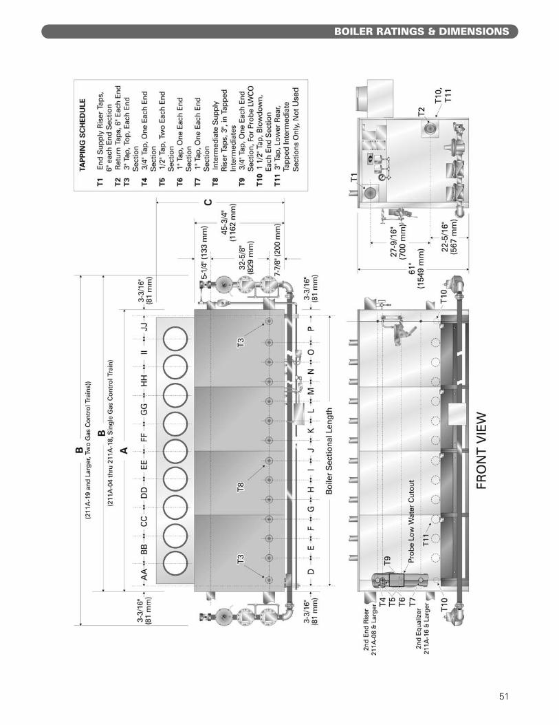
51
BOILER RATINGS & DIMENSIONS

52
BOILER RATINGS & DIMENSIONS
Boi
ler
Len
gth
& W
idth
Dim
ensi
ons
Boi
ler
Inte
rmed
iate
Inte
rmed
iate
Sup
ply/
Ret
urn
Loc
atio
ns
Mod
elS
ecti
onS
uppl
y/R
etur
n(D
imen
sion
s ar
e ap
prox
imat
e)
No.
AB
CLen
gth
DE
FG
HI
JK
LM
NO
P
211A
-04
28¹⁄₈
714
38³⁄₈
975
6316
021
³⁄₄
552
211A
-05
33³⁄₄
857
441,
118
6316
027
³⁄₈
695
211A
-06
39³⁄₈
1,00
050
¹⁄₄
1,27
665
165
3383
8
211A
-07
451,
143
55⁷⁄₈
1,41
963
160
38⁵⁄₈
981
211A
-08
50⁵⁄₈
1,28
661
³⁄₄
1,56
863
160
44¹⁄₄
1,12
4
211A
-09
56¹⁄₄
1,42
967
⁵⁄₈
1,71
863
160
49⁷⁄₈
1,26
7
211A
-10
61⁷⁄₈
1,57
273
¹⁄₄
1,86
165
165
55¹⁄₂
1,41
0
211A
-11
67¹⁄₂
1,71
580
³⁄₄
2,05
165
165
61¹⁄₈
1,55
3
211A
-12
73¹⁄₈
1,85
786
³⁄₈
2,19
463
160
66³⁄₄
1,69
5
211A
-13
78³⁄₄
2,00
091
¹⁄₂
2,32
463
160
72³⁄₈
1,83
8
211A
-14
84³⁄₈
2,14
397
¹⁄₈
2,46
765
165
781,
981
211A
-15
902,
286
102³
⁄₄2,
610
6516
583
⁵⁄₈
2,12
4
211A
-16
95⁵⁄₈
2,42
910
8³⁄₈
2,75
365
165
89¹⁄₄
2,26
7
211A
-17
101¹
⁄₄2,
572
114¹
⁄₄2,
902
6516
594
⁷⁄₈
2,41
0
211A
-18
106⁷
⁄₈2,
715
120³
⁄₈3,
058
6516
510
0¹⁄₂
2,55
353
¹⁄₁₆
1,34
847
⁷₁₆
1,20
5
211A
-19
112¹
⁄₂2,
858
139¹
⁄₈3,
534
6516
510
6¹⁄₈
2,69
653
¹⁄₁₆
1,34
853
¹₁₆
1,34
8
211A
-20
118¹
⁄₈3,
000
144³
⁄₄3,
677
6516
511
1³⁄₄
2,83
858
¹¹⁄₁₆
1,49
153
¹₁₆
1,34
8
211A
-21
123³
⁄₄3,
143
150³
⁄₈3,
820
6516
511
7³⁄₈
2,98
158
¹¹⁄₁₆
1,49
158
¹¹₁₆
1,49
1
211A
-22
129³
⁄₈3,
286
156
3,96
265
165
123
3,12
441
¹³⁄₁₆
1,06
245
1,14
336
³₁₆
919
211A
-23
135
3,42
916
1⁵⁄₈
4,10
565
165
128⁵
⁄₈3,
267
41¹³
⁄₁₆
1,06
245
1,14
341
¹³₁₆
1,06
2
211A
-24
140⁵
⁄₈3,
572
166³
⁄₈4,
226
6516
513
4¹⁄₄
3,41
047
⁷₁₆
1,20
545
1,14
341
¹³₁₆
1,06
2
211A
-25
146¹
⁄₄3,
715
172
4,36
965
165
139⁷
⁄₈3,
553
36³⁄₁₆
919
33³⁄₄
857
33³⁄₄
857
36³₁₆
919
211A
-26
151⁷
⁄₈3,
858
177⁵
⁄₈4,
512
6516
514
5¹⁄₂
3,69
636
³⁄₁₆
919
33³⁄₄
857
39³⁄₈
1,00
036
³₁₆
919
211A
-27
157¹
⁄₂4,
001
183¹
⁄₄4,
655
6516
515
1¹⁄₈
3,83
936
³⁄₁₆
919
28¹⁄₈
714
28¹⁄₈
714
28¹⁄₈
714
30⁹₁₆
776
211A
-28
163¹
⁄₈4,
143
188⁷
⁄₈4,
797
6516
515
6³⁄₄
3,98
124
¹⁵⁄₁₆
633
33³⁄₄
857
33³⁄₄
857
33³⁄₄
857
30⁹₁₆
776
211A
-29
168³
⁄₄4,
286
194¹
⁄₂4,
940
6516
516
2³⁄₈
4,12
42
324
¹⁵⁄₁₆
633
28¹⁄₈
714
28¹⁄₈
714
28¹⁄₈
714
28¹⁄₈
714
24
¹⁵₁₆
63
3
211A
-30
174³
⁄₈4,
429
200¹
⁄₈5,
083
6516
516
84,
267
23
30⁹₁₆
776
28¹⁄₈
714
28¹⁄₈
714
28¹⁄₈
714
28¹⁄₈
714
24
¹⁵₁₆
63
3
211A
-31
180
4,57
220
5³⁄₄
5,22
665
165
173⁵
⁄₈4,
410
23
30⁹₁₆
776
22¹⁄₂
572
22¹⁄₂
572
22¹⁄₂
572
22¹⁄₂
572
22¹⁄₂
572
30⁹₁₆
77
6
211A
-32
185⁵
⁄₈4,
715
21
1⁷⁄₈
5,38
265
165
179¹
⁄₄4,
553
23
30⁹₁₆
776
28¹⁄₈
714
22¹⁄₂
572
22¹⁄₂
572
22¹⁄₂
572
22¹⁄₂
572
30⁹₁₆
77
6
211A
-33
191¹
⁄₄4,
858
217¹
⁄₂5,
525
6516
518
4⁷⁄₈
4,69
62
324
¹⁵⁄₁₆
633
22¹⁄₂
572
22¹⁄₂
572
22¹⁄₂
572
22¹⁄₂
572
22¹⁄₂
572
22¹⁄₂
572
24
¹⁵₁₆
633
211A
-34
196⁷
⁄₈5,
001
223⁷
⁄₈5,
686
6516
519
0¹⁄₂
4,83
93
324
¹⁵⁄₁₆
633
22¹⁄₂
572
22¹⁄₂
572
22¹⁄₂
572
28¹⁄₈
714
22¹⁄₂
572
22¹⁄₂
572
24
¹⁵₁₆
633
211A
-35
202¹
⁄₂5,
144
229¹
⁄₂5,
829
6516
519
6¹⁄₈
4,98
23
324
¹⁵⁄₁₆
633
22¹⁄₂
572
22¹⁄₂
572
28¹⁄₈
714
28¹⁄₈
714
22¹⁄₂
572
22¹⁄₂
572
24
¹⁵₁₆
633
211A
-36
208¹
⁄₈5,
286
262
6,65
565
165
201³
⁄₄5,
124
33
24¹⁵
⁄₁₆
633
22¹⁄₂
572
22¹⁄₂
572
22¹⁄₂
572
22¹⁄₂
572
22¹⁄₂
572
22¹⁄₂
572
22¹⁄₂
572
19⁵₁₆
491
211A
-37
213³
⁄₄5,
429
268
6,80
765
165
207³
⁄₈5,
267
33
24¹⁵
⁄₁₆
633
22¹⁄₂
572
22¹⁄₂
572
22¹⁄₂
572
22¹⁄₂
572
22¹⁄₂
572
22¹⁄₂
572
22¹⁄₂
572
24
¹⁵₁₆
633
211A
-38
219³
⁄₈5,
572
273¹
⁄₂6,
947
6516
521
35,
410
33
19⁵⁄₁₆
491
22¹⁄₂
572
22¹⁄₂
572
28¹⁄₈
714
28¹⁄₈
714
28¹⁄₈
714
22¹⁄₂
572
22¹⁄₂
572
19⁵₁₆
491
211A
-39
225
5,71
527
9¹⁄₂
7,09
965
165
218⁵
⁄₈5,
553
33
19⁵⁄₁₆
491
22¹⁄₂
572
22¹⁄₂
572
22¹⁄₂
572
22¹⁄₂
572
22¹⁄₂
572
22¹⁄₂
572
22¹⁄₂
572
22¹⁄₂
572
19⁵₁₆
491
211A
-40
230⁵
⁄₈5,
858
285
7,23
965
165
224¹
⁄₄5,
696
43
19⁵⁄₁₆
491
22¹⁄₂
572
22¹⁄₂
572
22¹⁄₂
572
28¹⁄₈
714
22¹⁄₂
572
22¹⁄₂
572
22¹⁄₂
572
22¹⁄₂
572
19⁵₁₆
491
211A
-41
236¹
⁄₄6,
001
291
7,39
165
165
229⁷
⁄₈5,
839
43
19⁵⁄₁₆
491
22¹⁄₂
572
22¹⁄₂
572
22¹⁄₂
572
16⁷⁄₈
429
22¹⁄₂
572
16⁷⁄₈
429
22¹⁄₂
572
22¹⁄₂
572
22¹⁄₂
572
19⁵₁₆
491
211A
-42
241⁷
⁄₈6,
144
296¹
⁄₂7,
531
6516
523
5¹⁄₂
5,98
24
319
⁵⁄₁₆
491
22¹⁄₂
572
22¹⁄₂
572
22¹⁄₂
572
22¹⁄₂
572
16⁷⁄₈
429
22¹⁄₂
572
22¹⁄₂
572
22¹⁄₂
572
22¹⁄₂
572
19⁵₁₆
491
211A
-43
247¹
⁄₂6,
287
302¹
⁄₂7,
684
6516
524
1¹⁄₈
6,12
55
319
⁵⁄₁₆
491
16⁷⁄₈
429
22¹⁄₂
572
16⁷⁄₈
429
22¹⁄₂
572
22¹⁄₂
572
22¹⁄₂
572
22¹⁄₂
572
16⁷⁄₈
429
22¹⁄₂
572
16⁷⁄₈
429
19⁵₁₆
491
211A
-44
253¹
⁄₈6,
429
308
7,82
365
165
246³
⁄₄6,
267
53
19⁵⁄₁₆
491
22¹⁄₂
572
22¹⁄₂
572
22¹⁄₂
572
16⁷⁄₈
429
22¹⁄₂
572
16⁷⁄₈
429
16⁷⁄₈
429
22¹⁄₂
572
22¹⁄₂
572
22¹⁄₂
572
19⁵₁₆
491
211A
-45
258³
⁄₄6,
572
314
7,97
665
165
252³
⁄₈6,
410
53
19⁵⁄₁₆
491
16⁷⁄₈
429
22¹⁄₂
572
16⁷⁄₈
429
22¹⁄₂
572
16⁷⁄₈
429
22¹⁄₂
572
16⁷⁄₈
429
22¹⁄₂
572
16⁷⁄₈
429
22¹⁄₂
572
16⁷⁄₈
429
19⁵₁₆
491
211A
-46
264³
⁄₈6,
715
319¹
⁄₂8,
115
6516
525
86,
553
63
19⁵⁄₁₆
491
16⁷⁄₈
429
22¹⁄₂
572
16⁷⁄₈
429
22¹⁄₂
572
22¹⁄₂
572
16⁷⁄₈
429
22¹⁄₂
572
22¹⁄₂
572
16⁷⁄₈
429
22¹⁄₂
572
16⁷⁄₈
429
19⁵₁₆
491
SE
RIE
S 2
11A
STE
AM
BO
ILE
R D
IME
NS
ION
S
inch
inch
inch
inch
inch
inch
inch
inch
inch
inch
mm
mm
mm
mm
mm
mm
mm
mm
mm
mm
mm
Size
No.
inch
inch
inch
inch
inch
inch
inch
mm
mm
mm
mm
mm
mm
Cha
rt c
ontin
ues
on p
age
51.

53
BOILER RATINGS & DIMENSIONS
Boi
ler
Flu
e C
onne
ctio
n C
ente
r Lin
esFlu
e C
onne
ctio
nsV
ent
Chi
mne
y
Mod
elC
onne
ctor
Dia
met
er x
No.
AA
BB
CC
DD
EE
FF
GG
HH
IIJJ
Siz
eD
iam
eter
20ft
(6m
) hi
gh
211A
-04
10⁷⁄₈
276
10⁷⁄₈
276
112
305
1230
512
305
211A
-05
13³⁄₄
349
13⁵⁄₈
346
112
305
1230
512
305
211A
-06
16¹⁄₂
419
16¹⁄₂
419
114
356
1435
614
356
211A
-07
10⁷⁄₈
276
16⁷⁄₈
429
10⁷⁄₈
276
212
305
1435
614
356
211A
-08
13³⁄₄
349
19⁵⁄₈
498
10⁷⁄₈
276
212
305
1538
115
381
211A
-09
13
³⁄₄
349
22¹⁄₂
572
13⁵⁄₈
346
212
305
1640
616
406
211A
-10
16¹⁄₂
419
25³⁄₈
645
13⁵⁄₈
346
214
356
1743
217
432
211A
-11
16¹⁄₂
419
28¹⁄₈
714
16¹⁄₂
419
214
356
1845
718
457
211A
-12
13³⁄₄
349
22¹⁄₂
572
19⁵⁄₈
498
10⁷⁄₈
276
312
305
1845
718
457
211A
-13
13³⁄₄
349
22¹⁄₂
572
22¹⁄₂
572
13⁵⁄₈
346
312
305
1948
319
483
211A
-14
16¹⁄₂
419
25³⁄₈
645
22¹⁄₂
572
13⁵⁄₈
346
314
356
2050
820
508
211A
-15
16¹⁄₂
419
25³⁄₈
645
25³⁄₈
641
16¹⁄₂
419
314
356
2153
321
533
211A
-16
16¹⁄₂
419
28¹⁄₈
714
28¹⁄₈
714
16¹⁄₂
419
314
356
2153
321
533
211A
-17
13³⁄₄
349
22¹⁄₂
572
22¹⁄₂
572
22¹⁄₂
572
13⁵⁄₈
346
414
356
2255
922
559
211A
-18
16¹⁄₂
419
25³⁄₈
645
22¹⁄₂
572
22¹⁄₂
572
13⁵⁄₈
346
414
356
2358
423
584
211A
-19
13³⁄₄
349
25³⁄₈
645
28¹⁄₈
714
25³⁄₈
641
13⁵⁄₈
346
414
356
2358
423
584
211A
-20
16¹⁄₂
419
28¹⁄₈
714
28¹⁄₈
714
25³⁄₈
645
13⁵⁄₈
346
414
356
2461
024
610
211A
-21
16¹⁄₂
419
28¹⁄₈
714
28¹⁄₈
714
28¹⁄₈
714
16¹⁄₂
419
414
356
2563
525
635
211A
-22
16¹⁄₂
419
25³⁄₈
645
22¹⁄₂
572
22¹⁄₂
572
22¹⁄₂
572
13⁵⁄₈
346
514
356
2563
525
635
211A
-23
16¹⁄₂
419
28¹⁄₈
714
25³⁄₈
645
22¹⁄₂
572
22¹⁄₂
572
13⁵⁄₈
346
514
356
2666
026
660
211A
-24
16¹⁄₂
419
28¹⁄₈
714
28¹⁄₈
714
25³⁄₈
645
22¹⁄₂
572
13⁵⁄₈
346
514
356
2666
026
660
211A
-25
16¹⁄₂
419
28¹⁄₈
714
28¹⁄₈
714
28¹⁄₈
714
25³⁄₈
645
13⁵⁄₈
346
514
356
2768
627
686
211A
-26
16¹⁄₂
419
28¹⁄₈
714
28¹⁄₈
714
28¹⁄₈
714
28¹⁄₈
714
16¹⁄₂
419
514
356
2768
627
686
211A
-27
16¹⁄₂
419
28¹⁄₈
714
25³⁄₈
645
22¹⁄₂
572
22¹⁄₂
572
22¹⁄₂
572
13⁵⁄₈
346
614
356
2871
128
711
211A
-28
16¹⁄₂
419
28¹⁄₈
714
28¹⁄₈
714
25³⁄₈
645
22¹⁄₂
572
22¹⁄₂
572
13⁵⁄₈
346
614
356
2973
729
737
211A
-29
16¹⁄₂
419
28¹⁄₈
714
28¹⁄₈
714
28¹⁄₈
714
25³⁄₈
645
22¹⁄₂
572
13⁵⁄₈
346
614
356
2973
729
737
211A
-30
16¹⁄₂
419
28¹⁄₈
714
28¹⁄₈
714
28¹⁄₈
714
28¹⁄₈
714
25³⁄₈
645
13⁵⁄₈
346
614
356
3076
230
762
211A
-31
16¹⁄₂
419
28¹⁄₈
714
28¹⁄₈
714
28¹⁄₈
714
28¹⁄₈
714
28¹⁄₈
714
16¹⁄₂
419
614
356
3076
230
762
211A
-32
16¹⁄₂
419
28¹⁄₈
714
28¹⁄₈
714
25³⁄₈
645
22¹⁄₂
572
22¹⁄₂
572
22¹⁄₂
572
13⁵⁄₈
346
714
356
3178
731
787
211A
-33
16¹⁄₂
419
28¹⁄₈
714
28¹⁄₈
714
28¹⁄₈
714
25³⁄₈
645
22¹⁄₂
572
22¹⁄₂
572
13⁵⁄₈
346
714
356
3178
731
787
211A
-34
16¹⁄₂
419
28¹⁄₈
714
28¹⁄₈
714
28¹⁄₈
714
28¹⁄₈
714
25³⁄₈
645
22¹⁄₂
572
13⁵⁄₈
346
714
356
3281
332
813
211A
-35
16¹⁄₂
419
28¹⁄₈
714
28¹⁄₈
714
28¹⁄₈
714
28¹⁄₈
714
28¹⁄₈
714
25³⁄₈
645
13⁵⁄₈
346
714
356
3281
332
813
211A
-36
16¹⁄₂
419
28¹⁄₈
714
28¹⁄₈
714
28¹⁄₈
714
28¹⁄₈
714
28¹⁄₈
714
28¹⁄₈
714
16¹⁄₂
419
714
356
3383
833
838
211A
-37
16¹⁄₂
419
28¹⁄₈
714
28¹⁄₈
714
28¹⁄₈
714
25³⁄₈
645
22¹⁄₂
572
22¹⁄₂
572
22¹⁄₂
572
13⁵⁄₈
346
814
356
3383
833
838
211A
-38
13³⁄₄
349
22¹⁄₂
572
22¹⁄₂
572
25³⁄₈
641
28¹⁄₈
714
28¹⁄₈
714
28¹⁄₈
714
28¹⁄₈
714
16¹⁄₂
419
814
356
3486
434
864
211A
-39
13³⁄₄
349
22¹⁄₂
572
25³⁄₈
641
28¹⁄₈
714
28¹⁄₈
714
28¹⁄₈
714
28¹⁄₈
714
28¹⁄₈
714
16¹⁄₂
419
814
356
3486
434
864
211A
-40
13³⁄₄
349
25¹⁄₄
641
28¹⁄₈
714
28¹⁄₈
714
28¹⁄₈
714
28¹⁄₈
714
28¹⁄₈
714
28¹⁄₈
714
16¹⁄₂
419
814
356
3588
935
889
211A
-41
16¹⁄₂
419
28¹⁄₈
714
28¹⁄₈
714
28¹⁄₈
714
28¹⁄₈
714
28¹⁄₈
714
28¹⁄₈
714
28¹⁄₈
714
16¹⁄₂
419
814
356
3588
935
889
211A
-42
13³⁄₄
349
22¹⁄₂
572
22¹⁄₂
572
22¹⁄₂
572
25³⁄₈
641
28¹⁄₈
714
28¹⁄₈
714
28¹⁄₈
714
28¹⁄₈
714
16¹⁄₂
419
914
356
3691
436
914
211A
-43
13³⁄₄
349
22¹⁄₂
572
22¹⁄₂
572
25³⁄₈
641
28¹⁄₈
714
28¹⁄₈
714
28¹⁄₈
714
28¹⁄₈
714
28¹⁄₈
714
16¹⁄₂
419
914
356
3691
436
914
211A
-44
13³⁄₄
349
22¹⁄₂
572
25³⁄₈
641
28¹⁄₈
714
28¹⁄₈
714
28¹⁄₈
714
28¹⁄₈
714
28¹⁄₈
714
28¹⁄₈
714
16¹⁄₂
419
914
356
3691
436
914
211A
-45
13³⁄₄
349
25¹⁄₄
641
28¹⁄₈
714
28¹⁄₈
714
28¹⁄₈
714
28¹⁄₈
714
28¹⁄₈
714
28¹⁄₈
714
28¹⁄₈
714
16¹⁄₂
419
914
356
3794
037
940
211A
-46
16¹⁄₂
419
28¹⁄₈
714
28¹⁄₈
714
28¹⁄₈
714
28¹⁄₈
714
28¹⁄₈
714
28¹⁄₈
714
28¹⁄₈
714
28¹⁄₈
714
16¹⁄₂
419
914
356
3794
037
940
SE
RIE
S 2
11A
STE
AM
BO
ILE
R D
IME
NS
ION
S
No.
inch
inch
inch
inch
inch
inch
inch
inch
inch
inch
inch
inch
inch
mm
mm
mm
mm
mm
mm
mm
mm
mm
mm
mm
mm
mm

54
REPAIR PARTS – SERIES 211A™
15. REPAIR PARTS – SERIES 211A™Repair parts are available from your local PB Heat, LLC distributor or from Parts To YourDoor at 1 (610) 916-5380 (www.partstoyourdoor.com).Note: Remember to include the boiler model number and serial number when ordering parts.
Figure 15.1: Block/Flue Collector/Draft Hood Repair Parts

55
REPAIR PARTS – SERIES 211A™
DescriptionQuantityRequired
StockCode
1Right Hand End Section (50 psi) – GG1024 – 90059
Right Hand End Section (80 psi) – GG1024-1 – 90060
2Left Hand End Section (50 psi) – GG1023 – 90625
Left Hand End Section (80 psi) – GG1023-1 – 90626
3Plain Intermediate Section (50 psi) – GG1000 – 90356
Plain Intermediate Section (80 psi) – GG1000-1 – 90357
4Tapped Intermediate Section (50 psi) – GG1025 – 90065
Tapped Intermediate Section (80 psi) – GG1025-1 – 90066
NotShown
Plain Intermediate Section w/ Inspection Tapping (50 psi) – GG1000-2 – 90358
Plain Intermediate Section w/ Inspection Tapping (80 psi) – GG1000-3 – 90359
5 Tie Rod 2 per Flueway 90090
6 Flow Port Gasket 2 per Flueway 51670
7 High Temperature Rope, Diameter 5/8" (16 mm) – 6-1/2' Length per Flueway – 55723
8 Cleanout Cover Plate with Insulation (set of 2) 1 90489
9
Draft Hood – Box 13 with 12" Dia. Outlet (For Flue Collector 5000)¹ – 90399
Draft Hood – Box 13A with 12" Dia. Outlet (For Flue Collector 5000-1)¹ – 90400
Draft Hood – Box 13B with 14" Dia. Outlet (For Flue Collector 5000-1)¹ – 90401
Draft Hood – Box 13A with 14" Dia. Outlet (For Flue Collector 5000-2)¹ – 90402
10
Flue Collector – Box 14 – GG-5000 (Includes 10A, 10B, 10C, 10D)² – 90557
Flue Collector – Box 14A – GG-5000-1 (Includes 10A, 10B, 10C, 10D)² – 90558
Flue Collector – Box 14B – GG-5000-2 (Includes 10A, 10B, 10C, 10D)² – 90559
10A Front Flue Collector Hook Bolt (1 per Flue Collector) 1 GG5003
10B Rear Flue Collector Hook Bolt (1 per Flue Collector) 1 GG5004
10C Flue Collector Mounting Bracket (1 per Flue Collector) 1 GG5005
10D High Temperature Rope, Diameter 5/8" (16 mm)- 10' Length per Flue Collector – 55723
1 See IOM Instructions Table 6.2 for Draft Hood Location Layout2 See IOM Instructions Table 4.1 for Flue Collector Location Layout
Table 15.1: Block/Flue Collector/Draft Hood Repair Parts

56
REPAIR PARTS – SERIES 211A™
Figure 15.2: Base Assembly Repair Parts
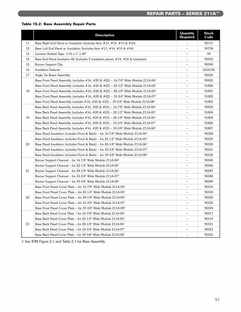
57
REPAIR PARTS – SERIES 211A™
Description QuantityRequired
StockCode
11 Base Right End Panel w/ Insulation (Includes Item #13, #14, #15 & #16) – 90737
12 Base Left End Panel w/ Insulation (Includes Item #13, #14, #15 & #16) – 90738
13 Ceramic Knitted Tape- 1/16 x 1" x 40" – 99
14 Base End Panel Insulation Kit (Includes 2 insulation pieces, #14, #16 & hardware) – 90333
15 Burner Support Clip – 90590
16 Insulation Fastener – GG2104
17 Angle Tie Brace Assembly – 90326
18
Base Front Panel Assembly (includes #16, #20 & #22) – 16-7/8" Wide Module 211A-04³ – 90932
Base Front Panel Assembly (includes #16, #20 & #22) – 22-1/2" Wide Module 211A-05³ – 91800
Base Front Panel Assembly (includes #16, #20 & #22) – 28-1/8" Wide Module 211A-06³ – 91801
Base Front Panel Assembly (includes #16, #20 & #22) – 33-3/4" Wide Module 211A-07³ – 91802
Base Front Panel Assembly includes #16, #20 & #22) – 39-3/8" Wide Module 211A-08³ – 91803
19
Base Back Panel Assembly (includes #16, #20 & #23) – 16-7/8" Wide Module 211A-04³ – 90934
Base Back Panel Assembly (includes #16, #20 & #23) – 22-1/2" Wide Module 211A-05³ – 91804
Base Back Panel Assembly (includes #16, #20 & #23) – 28-1/8" Wide Module 211A-06³ – 91805
Base Back Panel Assembly (includes #16, #20 & #23) – 33-3/4" Wide Module 211A-07³ – 91806
Base Back Panel Assembly (includes #16, #20 & #23) – 39-3/8" Wide Module 211A-08³ – 91807
20
Base Panel Insulation (includes Front & Back) – for 16-7/8" Wide Module 211A-04³ – 90328
Base Panel Insulation (includes Front & Back) – for 22-1/2" Wide Module 211A-05³ – 90329
Base Panel Insulation (includes Front & Back) – for 28-1/8" Wide Module 211A-06³ – 90330
Base Panel Insulation (includes Front & Back) – for 33-3/4" Wide Module 211A-07³ – 90331
Base Panel Insulation (includes Front & Back) – for 39-3/8" Wide Module 211A-08³ – 90332
21
Burner Support Channel – for 16-7/8" Wide Module 211A-04³ – 90585
Burner Support Channel – for 22-1/2" Wide Module 211A-05³ – 90586
Burner Support Channel – for 28-1/8" Wide Module 211A-06³ – 90587
Burner Support Channel – for 33-3/4" Wide Module 211A-07³ – 90588
Burner Support Channel – for 39-3/8" Wide Module 211A-08³ – 90589
22
Base Front Panel Cover Plate – for 16-7/8" Wide Module 211A-04³ – 90316
Base Front Panel Cover Plate – for 22-1/2" Wide Module 211A-05³ – 90318
Base Front Panel Cover Plate – for 28-1/8" Wide Module 211A-06³ – 90320
Base Front Panel Cover Plate – for 33-3/4" Wide Module 211A-07³ – 90322
Base Front Panel Cover Plate – for 39-3/8" Wide Module 211A-08³ – 90324
23
Base Back Panel Cover Plate – for 16-7/8" Wide Module 211A-04³ – 90317
Base Back Panel Cover Plate – for 22-1/2" Wide Module 211A-05³ – 90319
Base Back Panel Cover Plate – for 28-1/8" Wide Module 211A-06³ – 90321
Base Back Panel Cover Plate – for 33-3/4" Wide Module 211A-07³ – 90323
Base Back Panel Cover Plate – for 39-3/8" Wide Module 211A-08³ – 90325
Table 15.2: Base Assembly Repair Parts
3 See IOM Figure 2.1 and Table 2.1 for Base Assembly

58
REPAIR PARTS – SERIES 211A™
Figure 15.3: Jacket/Burner/Gas Manifold Repair Parts
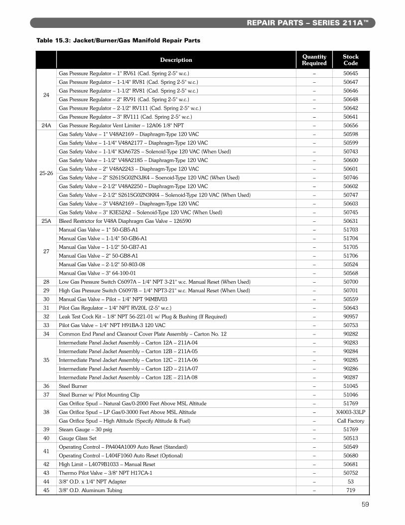
59
REPAIR PARTS – SERIES 211A™
Description QuantityRequired
StockCode
24
Gas Pressure Regulator – 1" RV61 (Cad. Spring 2-5" w.c.) – 50645
Gas Pressure Regulator – 1-1/4" RV81 (Cad. Spring 2-5" w.c.) – 50647
Gas Pressure Regulator – 1-1/2" RV81 (Cad. Spring 2-5" w.c.) – 50646
Gas Pressure Regulator – 2" RV91 (Cad. Spring 2-5" w.c.) – 50648
Gas Pressure Regulator – 2-1/2" RV111 (Cad. Spring 2-5" w.c.) – 50642
Gas Pressure Regulator – 3" RV111 (Cad. Spring 2-5" w.c.) – 50641
24A Gas Pressure Regulator Vent Limiter – 12A06 1/8" NPT – 50656
25-26
Gas Safety Valve – 1" V48A2169 – Diaphragm-Type 120 VAC – 50598
Gas Safety Valve – 1-1/4" V48A2177 – Diaphragm-Type 120 VAC – 50599
Gas Safety Valve – 1-1/4" K3A672S – Solenoid-Type 120 VAC (When Used) – 50743
Gas Safety Valve – 1-1/2" V48A2185 – Diaphragm-Type 120 VAC – 50600
Gas Safety Valve – 2" V48A2243 – Diaphragm-Type 120 VAC – 50601
Gas Safety Valve – 2" S261SG02N3JK4 – Soenoid-Type 120 VAC (When Used) – 50746
Gas Safety Valve – 2-1/2" V48A2250 – Diaphragm-Type 120 VAC – 50602
Gas Safety Valve – 2-1/2" S261SG02N3KK4 – Solenoid-Type 120 VAC (When Used) – 50747
Gas Safety Valve – 3" V48A2169 – Diaphragm-Type 120 VAC – 50603
Gas Safety Valve – 3" K3E52A2 – Solenoid-Type 120 VAC (When Used) – 50745
25A Bleed Restrictor for V48A Diaphragm Gas Valve – 126590 – 50631
27
Manual Gas Valve – 1" 50-GB5-A1 – 51703
Manual Gas Valve – 1-1/4" 50-GB6-A1 – 51704
Manual Gas Valve – 1-1/2" 50-GB7-A1 – 51705
Manual Gas Valve – 2" 50-GB8-A1 – 51706
Manual Gas Valve – 2-1/2" 50-803-08 – 50524
Manual Gas Valve – 3" 64-100-01 – 50568
28 Low Gas Pressure Switch C6097A – 1/4" NPT 3-21" w.c. Manual Reset (When Used) – 50700
29 High Gas Pressure Switch C6097B – 1/4" NPT3-21" w.c. Manual Reset (When Used) – 50701
30 Manual Gas Valve – Pilot – 1/4" NPT 94MBV03 – 50559
31 Pilot Gas Regulator – 1/4" NPT RV20L (2-5" w.c.) – 50643
32 Leak Test Cock Kit – 1/8" NPT 56-221-01 w/ Plug & Bushing (If Required) – 90957
33 Pilot Gas Valve – 1/4" NPT H91BA-3 120 VAC – 50753
34 Common End Panel and Cleanout Cover Plate Assembly – Carton No. 12 – 90282
35
Intermediate Panel Jacket Assembly – Carton 12A – 211A-04 – 90283
Intermediate Panel Jacket Assembly – Carton 12B – 211A-05 – 90284
Intermediate Panel Jacket Assembly – Carton 12C – 211A-06 – 90285
Intermediate Panel Jacket Assembly – Carton 12D – 211A-07 – 90286
Intermediate Panel Jacket Assembly – Carton 12E – 211A-08 – 90287
36 Steel Burner – 51045
37 Steel Burner w/ Pilot Mounting Clip – 51046
38
Gas Orifice Spud – Natural Gas/0-2000 Feet Above MSL Altitude – 51769
Gas Orifice Spud – LP Gas/0-3000 Feet Above MSL Altitude – X4003-33LP
Gas Orifice Spud – High Altitude (Specify Altitude & Fuel) – Call Factory
39 Steam Gauge – 30 psig – 51769
40 Gauge Glass Set – 50513
41Operating Control – PA404A1009 Auto Reset (Standard) – 50549
Operating Control – L404F1060 Auto Reset (Optional) – 50680
42 High Limit – L4079B1033 – Manual Reset – 50681
43 Thermo Pilot Valve – 3/8" NPT H17CA-1 – 50752
44 3/8" O.D. x 1/4" NPT Adapter – 53
45 3/8" O.D. Aluminum Tubing – 719
Table 15.3: Jacket/Burner/Gas Manifold Repair Parts

60
NOTES

211A™
Boilers – Steam
SeriesGas
Installation,Operation &MaintenanceManualTO THE INSTALLER:
This manual is the property of the owner and mustbe affixed near the boiler for future reference.
TO THE OWNER:This boiler should be inspected annually by aQualified Service Agency.
GG8051 R18 (11/17 - 5C)Printed in U.S.A.©2017 PB Heat, LLC. All rights reserved.
PB HEAT, LLC131 S. CHURCH STREET • BALLY, PA 19503