2016 USER GUIDE Version 2 of Contents Table of Contents Introduction Licensing & Installation Online...
92
2016 USER GUIDE Version 2.1
-
Upload
nguyenhanh -
Category
Documents
-
view
236 -
download
1
Transcript of 2016 USER GUIDE Version 2 of Contents Table of Contents Introduction Licensing & Installation Online...

2016
USER GUIDE Version 2.1
Table of Contents
Table of Contents Introduction Licensing & Installation
Online Activation Offline Activation
User Interface Overview Windows
Main Window The Tool Palette
Display Options Regular Display Full Screen Presentation Mode Presentation with Timecode Presentation with Toolbar Ribbon Timelines
Masks The Project Manager
Determining where your project metadata will be stored Creating a Project Creating a Clip Preparing a clip for work
Run Cut Detection The Bookmark Event Viewer Bookmark Event Viewer Hot Keys
Creating Versions Creating a Version of a Version Discarding Changes in a Version or Version of Version Committing Versions Deleting Versions
Understanding History Files Global Hot Keys Using the DRS™ Tool
Drawing Your Fix Quick Select Rejecting or Accepting Pending Fixes Get Original Values (GOV)
Page 1 DRSTM Nova V2 User Guide
Repeat Last Action DRS™ Hot Keys
Using the Scratch Tool Using the PDL Scratch Hot Keys
Using the Paint Tool Reveal Mode Clone Mode Color Mode Original Values Mode
Get Original Values (GOV) Using Mask in the Paint Tool Paint Hot Keys
Using the AutoFilter Tool ROI Mode Filter Sets Parameters Example Usage Processing AutoFilter on Single Frames Using Mask in AutoFilter AutoFilter Hot Keys
Using the 3 Layer Tool Viewing a Single Channel Auto Per Shot Mode Auto Per Frame Mode Manual Mode Reference Frame Mode Analysis and Processing Region Using the PDL Apply Correction to Preview Frame Only 3 Layer Hot Keys
Using the Color Breathing/Flicker Tool Region of Interest Graph Keyframe Controls Segments and Groups Color Breathing/Flicker Hot Keys
Using the Stabilize Tool “Use SubPixel Interpolation” Processing Region Using the PDL Stabilization Hot Keys
Using the Dewarp Tool
Page 2 DRSTM Nova V2 User Guide
Dewarp Hot Heys Using the Grain Tool
Suggested Default Settings for Grain Tool “Reduce” How to save Presets for Grain “Create” Using Mask in Grain Grain Tool Hot Keys
Using the Filter Tool Aperture Correction
Suggested Setting for Aperture Correction Blur
Suggested Settings for Blur Using Mask in Filter Filter Tool Hot Keys
Page 3 DRSTM Nova V2 User Guide
Introduction Welcome to DRS™ Nova, the first and leading digital film restoration software used by companies and libraries all over the world to restore their films to a pristine state. DRS™ Nova consists of multiple modules developed to address the myriad of issues encountered in the film restoration process. It is designed with the artist in mind, intended to be easy to learn while providing a comprehensive toolset. Here is a list of all the modules available in Version 2: DRS™ The original unique digital film restoration algorithm fixes dust, debris, scratches, tears and more AutoFilter Automatically detect and repair dust and defects across a range of frames. Scratch Automatically repairs persistent scratches Paint The Paint tool offers complete precision for manual fixes of everything from dust and debris to film tears and gate hairs Color Flicker Automatically reduce density and color shifts to eliminate flicker and color breathing due to emulsion fading Project Management Powerful Tools to manage your media Stabilize & Dewarp Automatically repair jitter, gate weave, splice bumps and any other type of geometric distortion 3 Layer Realign misregistered RGB layers, including individual channel warping Reduce Grain Smooth out grainy or noisy images Add Grain Create custom grain patterns and apply selectively or universally across a range of frames ImageFilter Apply aperture correction or blurring to a scene. DRS™ Nova is resolution independent so you can work in any resolution for files that are DPX, TIFF, or EXR. Enjoy your time restoring your favorite films and visit forum.mtifilm.com for helpful hints and suggestions.
Page 4 DRSTM Nova V2 User Guide
Licensing & Installation The DRS™NOVA installer is available on the MTI Film Support Forum http://forum.mtifilm.com/t/drsnovainstaller/263 DRS™NOVA requires certain prerequisites, such as .NET, be installed. If your workstation is online during installation, the installer will guide you through downloading and installing these. If you will be offline, please download and install these prerequisites manually from http://forum.mtifilm.com/t/drsnovainstallerprerequisites/383
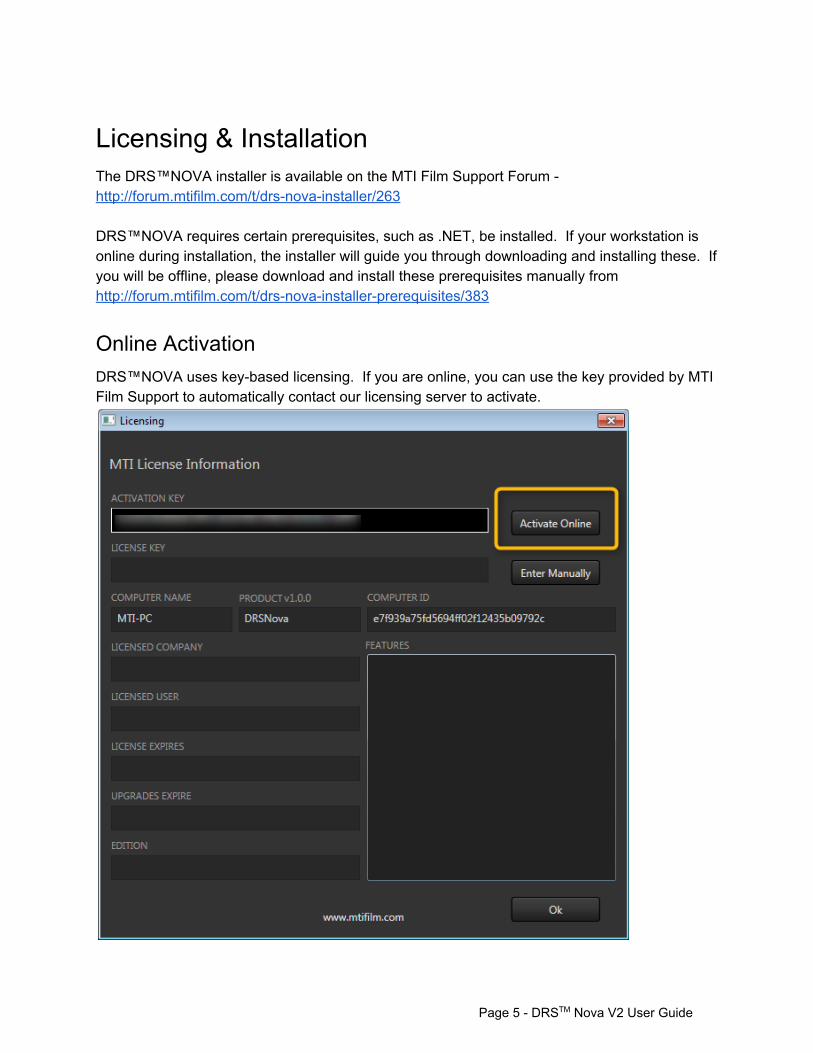
Online Activation DRS™NOVA uses keybased licensing. If you are online, you can use the key provided by MTI Film Support to automatically contact our licensing server to activate.
Page 5 DRSTM Nova V2 User Guide
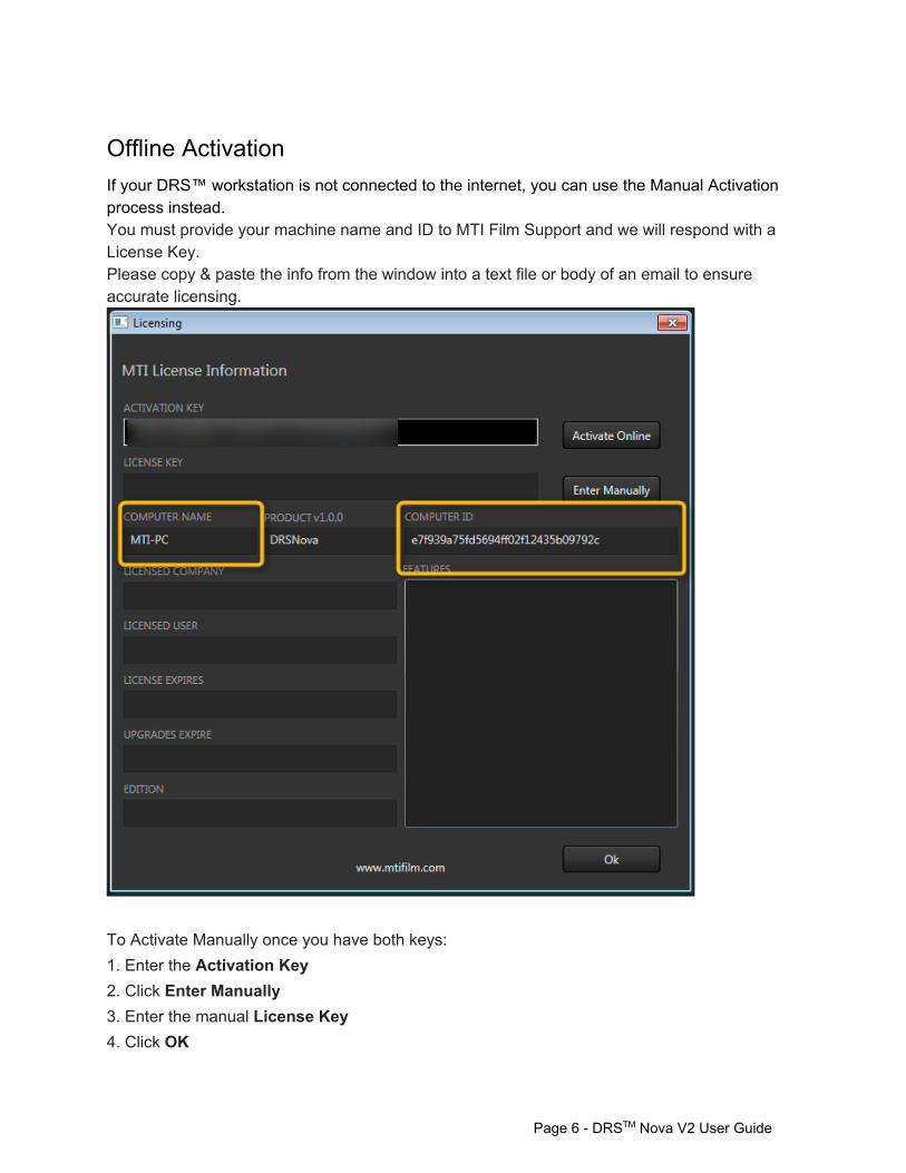
Offline Activation If your DRS™ workstation is not connected to the internet, you can use the Manual Activation process instead. You must provide your machine name and ID to MTI Film Support and we will respond with a License Key. Please copy & paste the info from the window into a text file or body of an email to ensure accurate licensing.
To Activate Manually once you have both keys: 1. Enter the Activation Key 2. Click Enter Manually 3. Enter the manual License Key 4. Click OK
Page 6 DRSTM Nova V2 User Guide
User Interface Overview
Windows
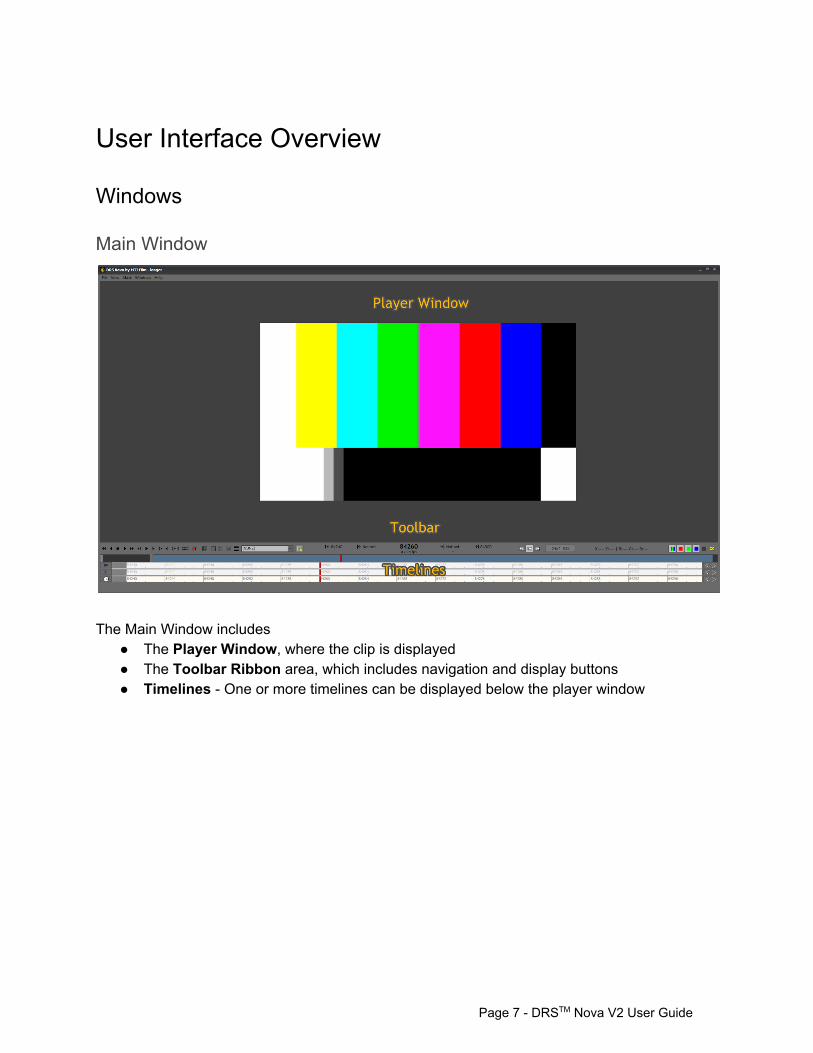
Main Window
The Main Window includes
The Player Window, where the clip is displayed The Toolbar Ribbon area, which includes navigation and display buttons Timelines One or more timelines can be displayed below the player window
Page 7 DRSTM Nova V2 User Guide
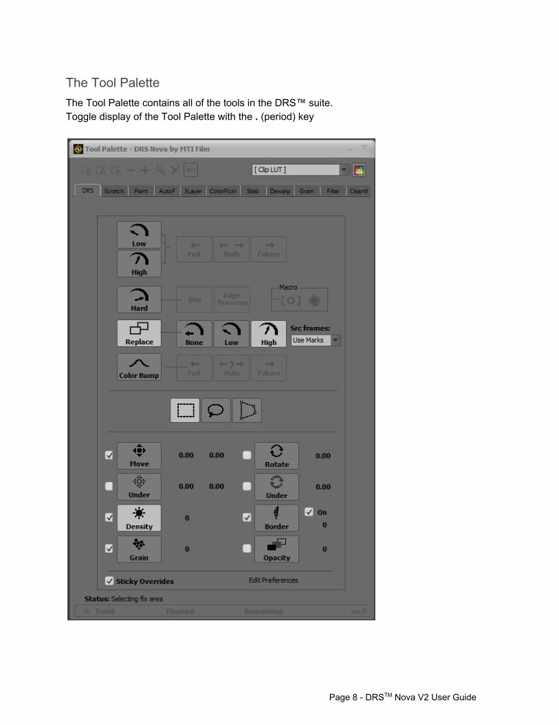
The Tool Palette The Tool Palette contains all of the tools in the DRS™ suite. Toggle display of the Tool Palette with the . (period) key
Page 8 DRSTM Nova V2 User Guide
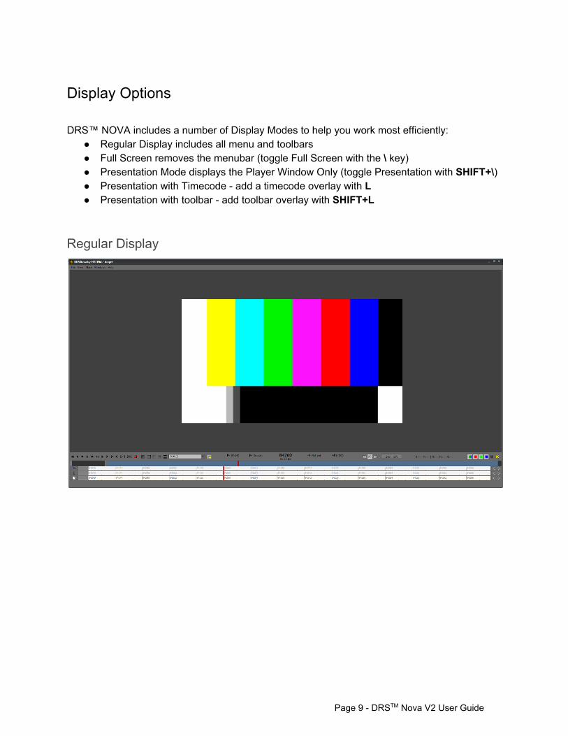
Display Options DRS™ NOVA includes a number of Display Modes to help you work most efficiently:
Regular Display includes all menu and toolbars Full Screen removes the menubar (toggle Full Screen with the \ key) Presentation Mode displays the Player Window Only (toggle Presentation with SHIFT+\) Presentation with Timecode add a timecode overlay with L Presentation with toolbar add toolbar overlay with SHIFT+L
Regular Display
Page 9 DRSTM Nova V2 User Guide
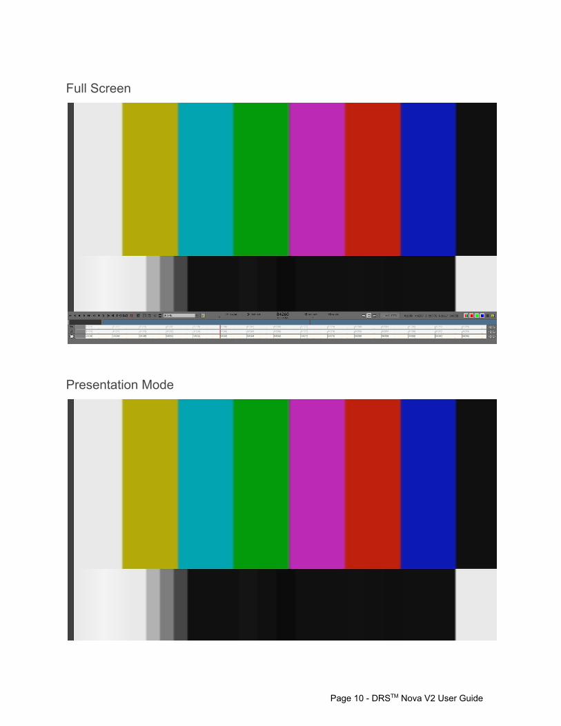
Full Screen
Presentation Mode
Page 10 DRSTM Nova V2 User Guide
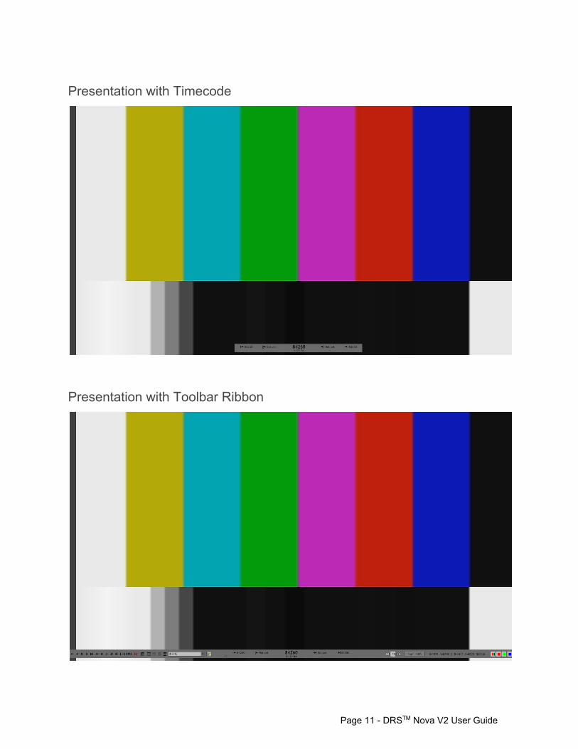
Presentation with Timecode
Presentation with Toolbar Ribbon
Page 11 DRSTM Nova V2 User Guide
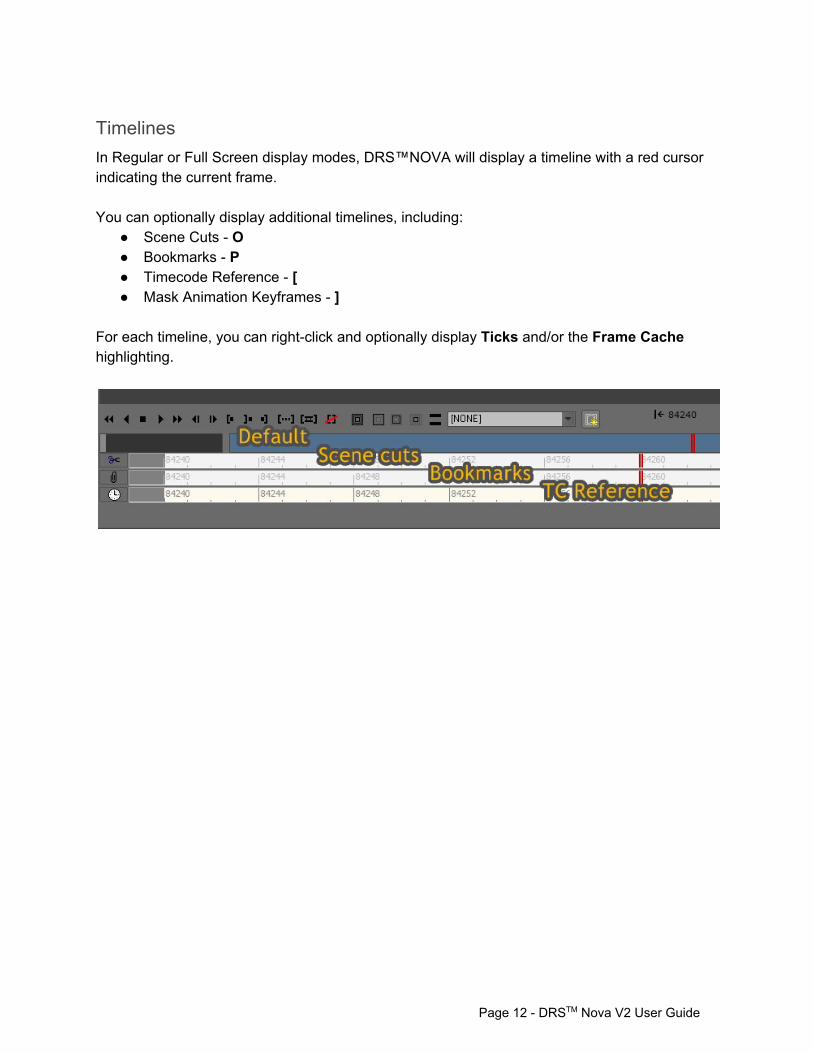
Timelines In Regular or Full Screen display modes, DRS™NOVA will display a timeline with a red cursor indicating the current frame. You can optionally display additional timelines, including:
Scene Cuts O Bookmarks P Timecode Reference [ Mask Animation Keyframes ]
For each timeline, you can rightclick and optionally display Ticks and/or the Frame Cache highlighting.
Page 12 DRSTM Nova V2 User Guide
Masks
Page 13 DRSTM Nova V2 User Guide
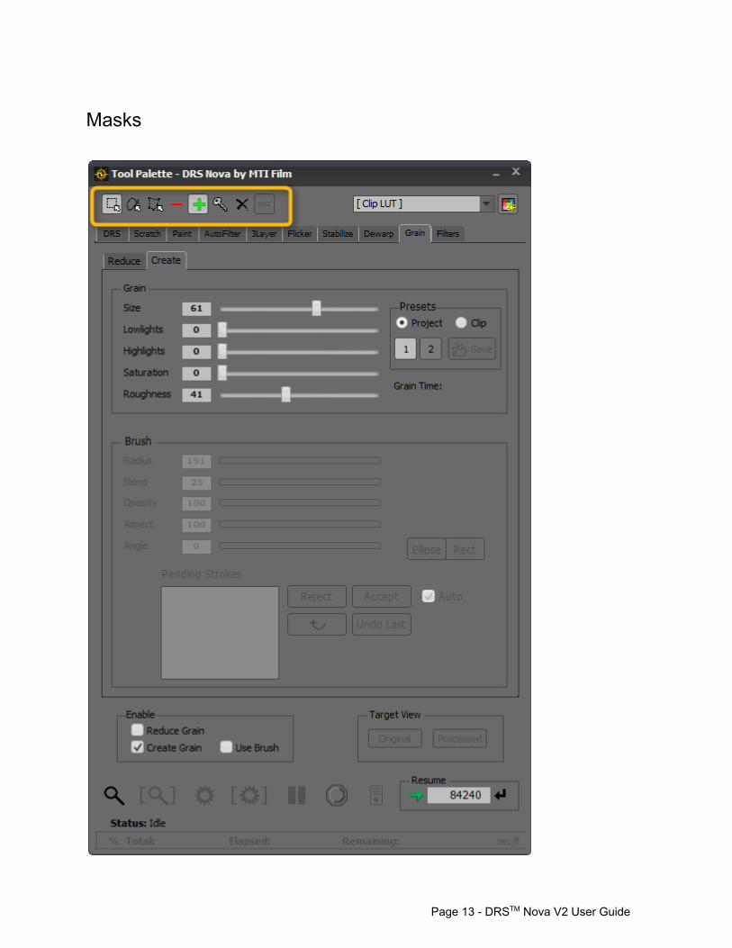
Masks allow you to include or exclude certain regions of the frame while processing in the following tools:
Paint AutoFilter Grain ImageFilter
The Mask toolbar appears at the top of the Tool Palette and will appear disabled in other tools. The following tools do not use Masks because they have their own internal Processing Region settings:
DRS™ Stabilize Dewarp Color/Flicker
Page 14 DRSTM Nova V2 User Guide
The Project Manager
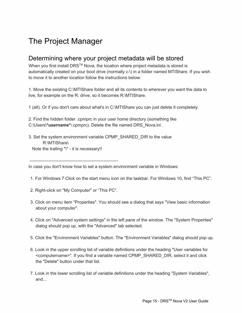
Determining where your project metadata will be stored When you first install DRSTM Nova, the location where project metadata is stored is automatically created on your boot drive (normally c:\) in a folder named MTIShare. If you wish to move it to another location follow the instructions below: 1. Move the existing C:\MTIShare folder and all its contents to wherever you want the data to live, for example on the R: drive, so it becomes R:\MTIShare. 1 (alt). Or if you don't care about what's in C:\MTIShare you can just delete it completely. 2. Find the hidden folder .cpmprc in your user home directory (something like C:\Users\*username*\.cpmprc). Delete the file named DRS_Nova.ini . 3. Set the system environment variable CPMP_SHARED_DIR to the value
R:\MTIShare\ Note the trailing "\" it is necessary!! In case you don't know how to set a system environment variable in Windows: 1. For Windows 7 Click on the start menu icon on the taskbar. For Windows 10, find “This PC”. 2. Rightclick on "My Computer" or “This PC”. 3. Click on menu item "Properties". You should see a dialog that says "View basic information
about your computer". 4. Click on "Advanced system settings" in the left pane of the window. The "System Properties"
dialog should pop up, with the "Advanced" tab selected. 5. Click the "Environment Variables" button. The "Environment Variables" dialog should pop up. 6. Look in the upper scrolling list of variable definitions under the heading "User variables for
<computername>". If you find a variable named CPMP_SHARED_DIR, select it and click the "Delete" button under that list.
7. Look in the lower scrolling list of variable definitions under the heading "System Variables",
and...
Page 15 DRSTM Nova V2 User Guide
a. If you find CPMP_SHARED_DIR, select it and click the "Edit" button. b. or, if the list does not contain CPMP_SHARED_DIR, click the "New" button, then in the popup enter CPMP_SHARED_DIR in the "Variable name" field.
8. Enter R:\MTIShare\ in the "Variable value" field. Click the "OK" button. Close all the dialogs.
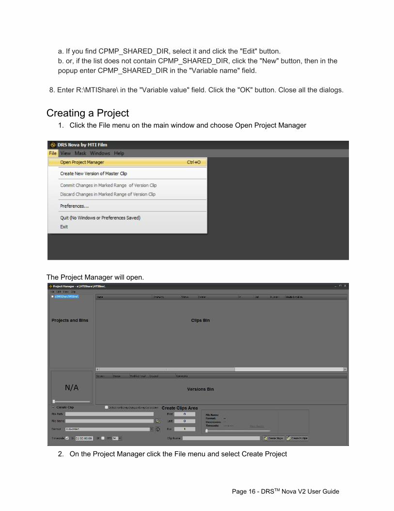
Creating a Project 1. Click the File menu on the main window and choose Open Project Manager
The Project Manager will open.
2. On the Project Manager click the File menu and select Create Project
Page 16 DRSTM Nova V2 User Guide
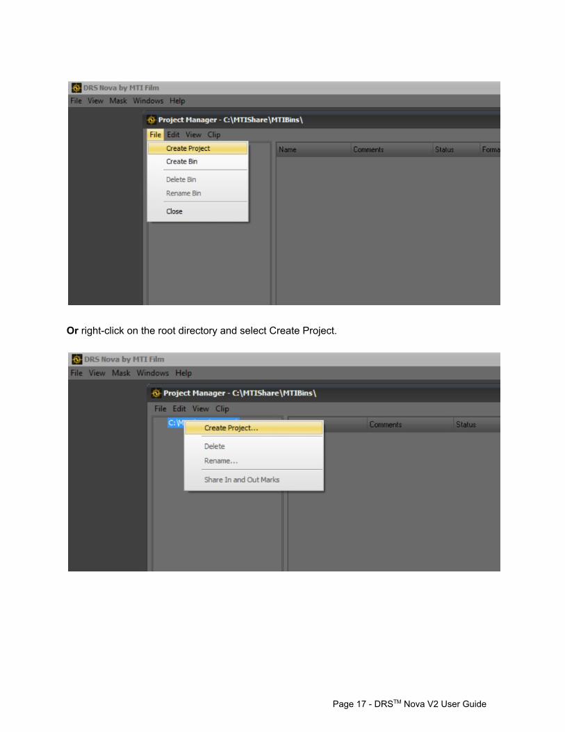
Or rightclick on the root directory and select Create Project.
Page 17 DRSTM Nova V2 User Guide
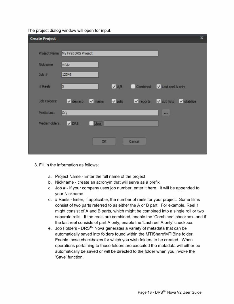
The project dialog window will open for input.
3. Fill in the information as follows:
a. Project Name Enter the full name of the project b. Nickname create an acronym that will serve as a prefix c. Job # If your company uses job number, enter it here. It will be appended to
your Nickname d. # Reels Enter, if applicable, the number of reels for your project. Some films
consist of two parts referred to as either the A or B part. For example, Reel 1 might consist of A and B parts, which might be combined into a single roll or two separate rolls. If the reels are combined, enable the ‘Combined’ checkbox, and if the last reel consists of part A only, enable the ‘Last reel A only’ checkbox.
e. Job Folders DRSTM Nova generates a variety of metadata that can be automatically saved into folders found within the MTIShare\MTIBins folder. Enable those checkboxes for which you wish folders to be created. When operations pertaining to those folders are executed the metadata will either be automatically be saved or will be directed to the folder when you invoke the ‘Save’ function.
Page 18 DRSTM Nova V2 User Guide
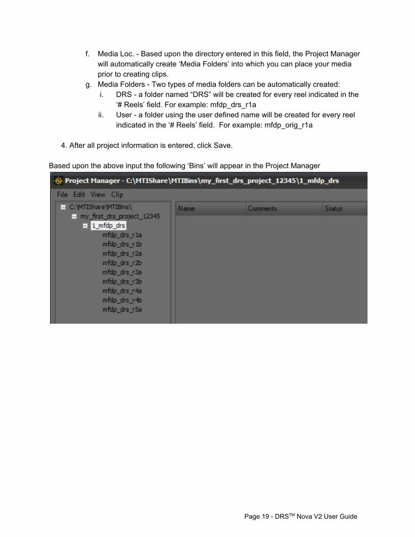
f. Media Loc. Based upon the directory entered in this field, the Project Manager will automatically create ‘Media Folders’ into which you can place your media prior to creating clips.
g. Media Folders Two types of media folders can be automatically created: i. DRS a folder named “DRS” will be created for every reel indicated in the
‘# Reels’ field. For example: mfdp_drs_r1a ii. User a folder using the user defined name will be created for every reel
indicated in the ‘# Reels’ field. For example: mfdp_orig_r1a
4. After all project information is entered, click Save.
Based upon the above input the following ‘Bins’ will appear in the Project Manager
Page 19 DRSTM Nova V2 User Guide
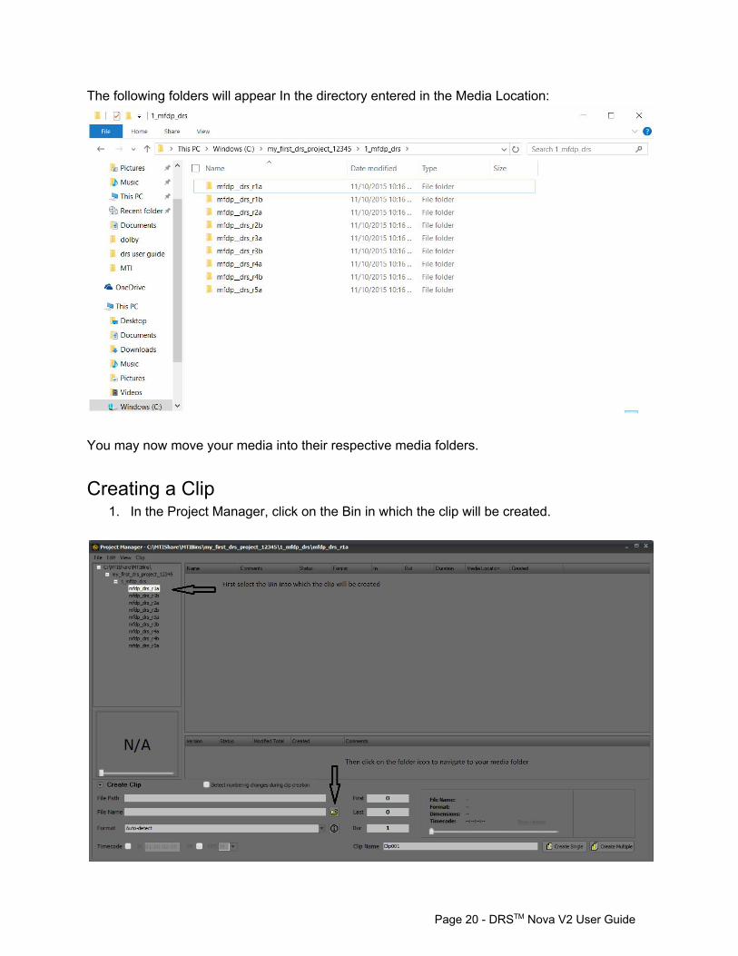
The following folders will appear In the directory entered in the Media Location:
You may now move your media into their respective media folders.
Creating a Clip 1. In the Project Manager, click on the Bin in which the clip will be created.
Page 20 DRSTM Nova V2 User Guide
2. Click the folder icon 3. Navigate to the media folder that contains the files for your clip 4. Open the folder and double click on the first frame of the file sequence 5. Enter a name in the Clip Name field and click the Create Single button or press enter
If you suspect that there are number breaks or changes in the file sequence then click the checkbox for “Detect numbering changes during clip creation”. This will force the end of the clip to be truncated to the last consecutive frame number in the sequence.
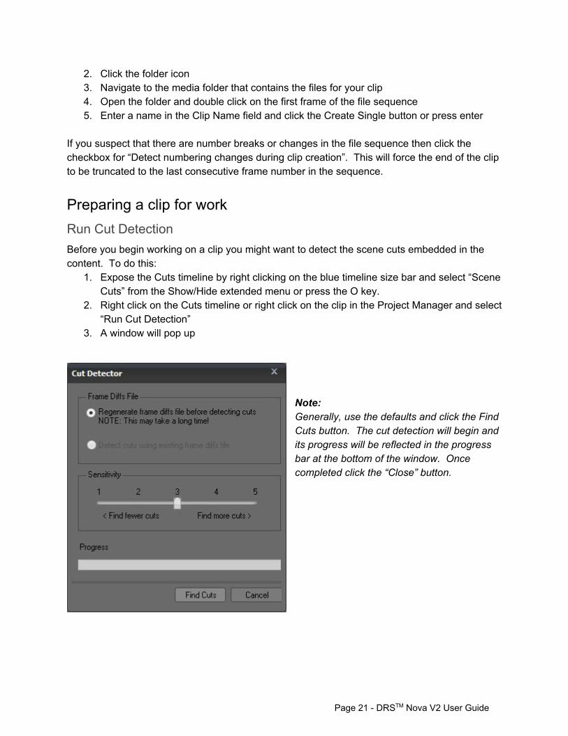
Preparing a clip for work Run Cut Detection Before you begin working on a clip you might want to detect the scene cuts embedded in the content. To do this:
1. Expose the Cuts timeline by right clicking on the blue timeline size bar and select “Scene Cuts” from the Show/Hide extended menu or press the O key.
2. Right click on the Cuts timeline or right click on the clip in the Project Manager and select “Run Cut Detection”
3. A window will pop up
Note: Generally, use the defaults and click the Find Cuts button. The cut detection will begin and its progress will be reflected in the progress bar at the bottom of the window. Once completed click the “Close” button.
Page 21 DRSTM Nova V2 User Guide
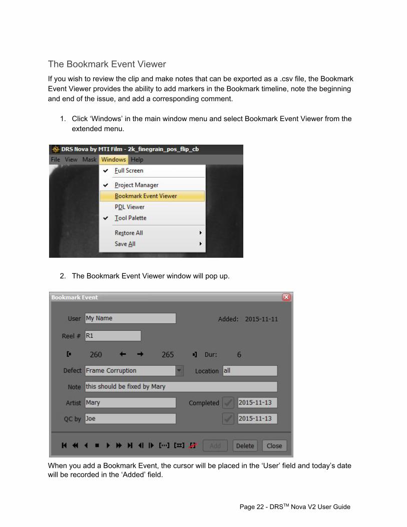
The Bookmark Event Viewer If you wish to review the clip and make notes that can be exported as a .csv file, the Bookmark Event Viewer provides the ability to add markers in the Bookmark timeline, note the beginning and end of the issue, and add a corresponding comment.
1. Click ‘Windows’ in the main window menu and select Bookmark Event Viewer from the extended menu.
2. The Bookmark Event Viewer window will pop up.
When you add a Bookmark Event, the cursor will be placed in the ‘User’ field and today’s date will be recorded in the ‘Added’ field.
Page 22 DRSTM Nova V2 User Guide
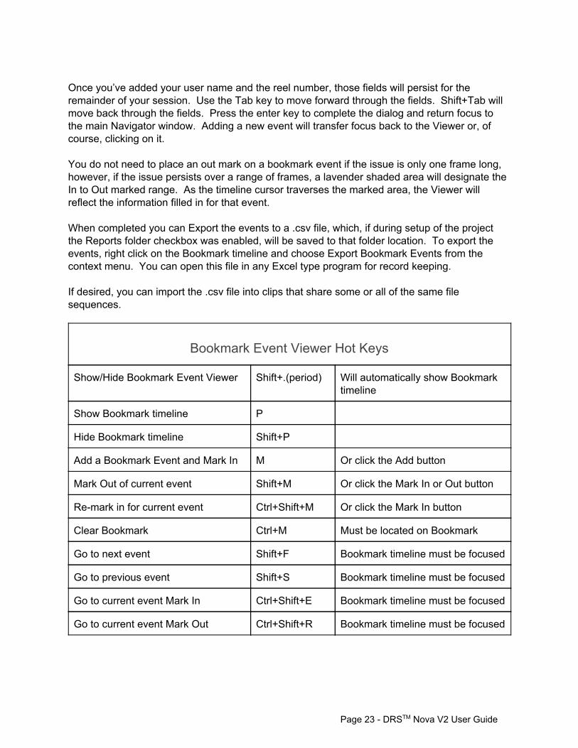
Once you’ve added your user name and the reel number, those fields will persist for the remainder of your session. Use the Tab key to move forward through the fields. Shift+Tab will move back through the fields. Press the enter key to complete the dialog and return focus to the main Navigator window. Adding a new event will transfer focus back to the Viewer or, of course, clicking on it. You do not need to place an out mark on a bookmark event if the issue is only one frame long, however, if the issue persists over a range of frames, a lavender shaded area will designate the In to Out marked range. As the timeline cursor traverses the marked area, the Viewer will reflect the information filled in for that event. When completed you can Export the events to a .csv file, which, if during setup of the project the Reports folder checkbox was enabled, will be saved to that folder location. To export the events, right click on the Bookmark timeline and choose Export Bookmark Events from the context menu. You can open this file in any Excel type program for record keeping. If desired, you can import the .csv file into clips that share some or all of the same file sequences.
Bookmark Event Viewer Hot Keys
Show/Hide Bookmark Event Viewer Shift+.(period) Will automatically show Bookmark timeline
Show Bookmark timeline P
Hide Bookmark timeline Shift+P
Add a Bookmark Event and Mark In M Or click the Add button
Mark Out of current event Shift+M Or click the Mark In or Out button
Remark in for current event Ctrl+Shift+M Or click the Mark In button
Clear Bookmark Ctrl+M Must be located on Bookmark
Go to next event Shift+F Bookmark timeline must be focused
Go to previous event Shift+S Bookmark timeline must be focused
Go to current event Mark In Ctrl+Shift+E Bookmark timeline must be focused
Go to current event Mark Out Ctrl+Shift+R Bookmark timeline must be focused
Page 23 DRSTM Nova V2 User Guide
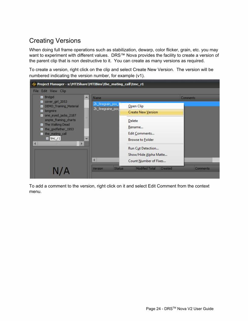
Creating Versions When doing full frame operations such as stabilization, dewarp, color flicker, grain, etc. you may want to experiment with different values. DRS™ Nova provides the facility to create a version of the parent clip that is non destructive to it. You can create as many versions as required.
To create a version, right click on the clip and select Create New Version. The version will be numbered indicating the version number, for example (v1).
To add a comment to the version, right click on it and select Edit Comment from the context menu.
Page 24 DRSTM Nova V2 User Guide
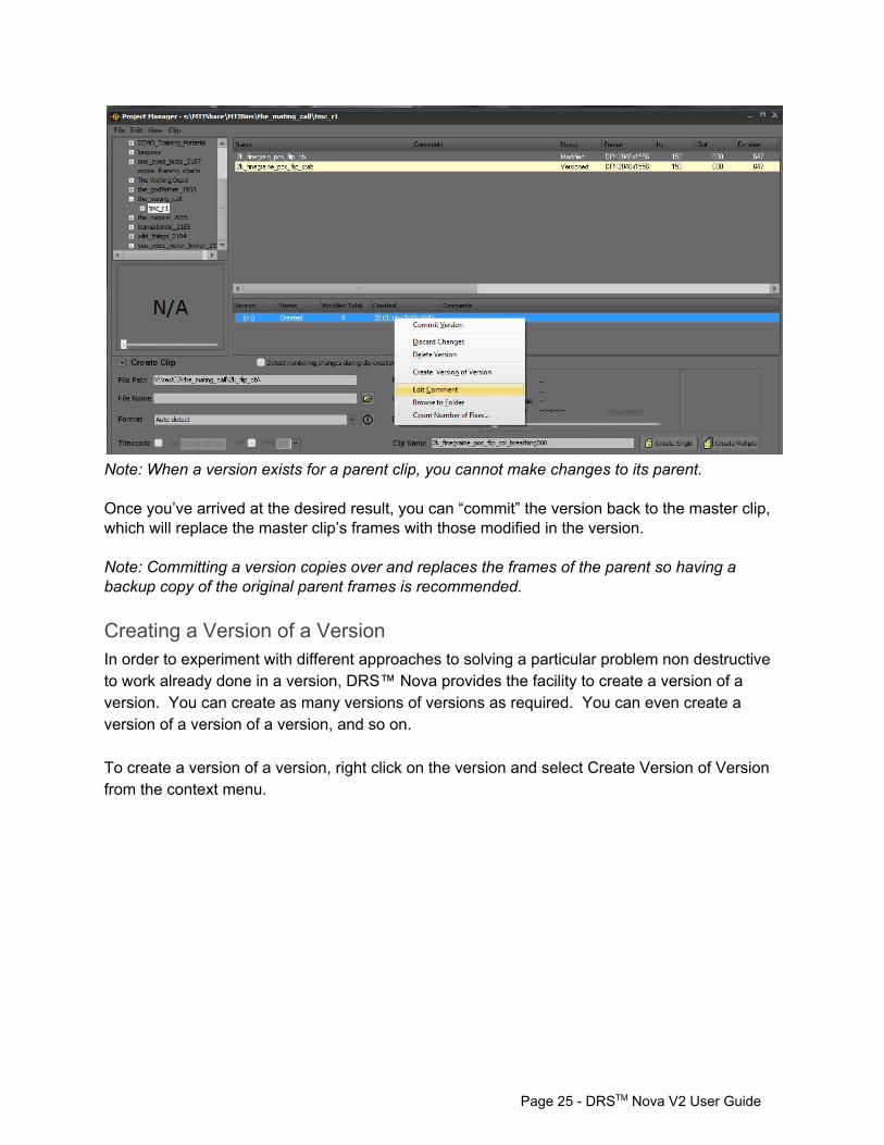
Note: When a version exists for a parent clip, you cannot make changes to its parent. Once you’ve arrived at the desired result, you can “commit” the version back to the master clip, which will replace the master clip’s frames with those modified in the version. Note: Committing a version copies over and replaces the frames of the parent so having a backup copy of the original parent frames is recommended.
Creating a Version of a Version In order to experiment with different approaches to solving a particular problem non destructive to work already done in a version, DRS™ Nova provides the facility to create a version of a version. You can create as many versions of versions as required. You can even create a version of a version of a version, and so on. To create a version of a version, right click on the version and select Create Version of Version from the context menu.
Page 25 DRSTM Nova V2 User Guide
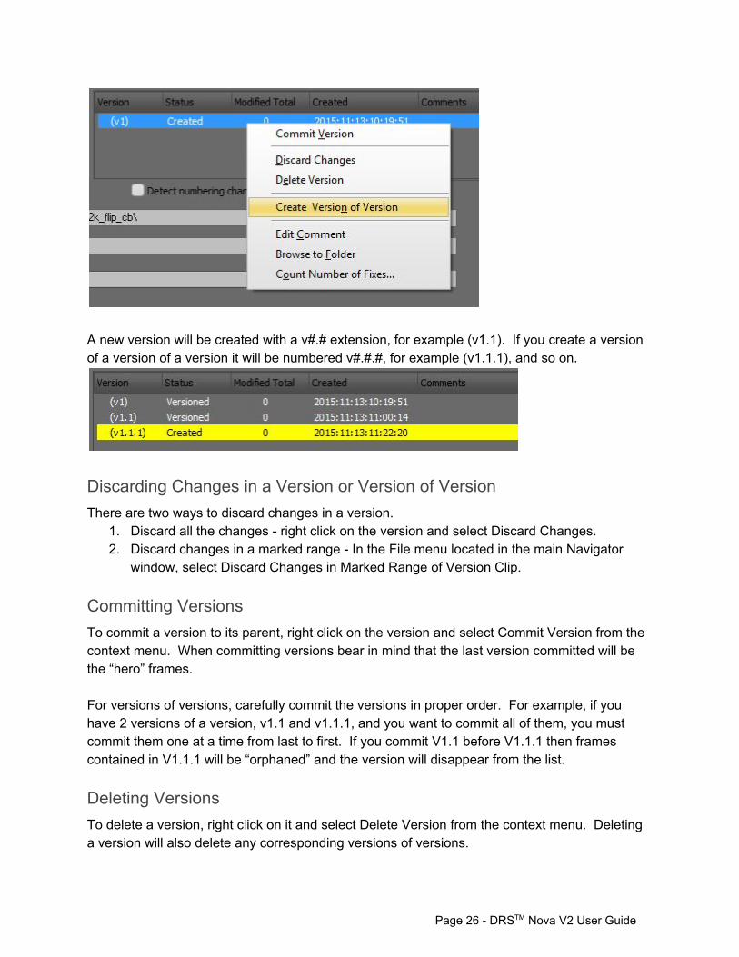
A new version will be created with a v#.# extension, for example (v1.1). If you create a version of a version of a version it will be numbered v#.#.#, for example (v1.1.1), and so on.
Discarding Changes in a Version or Version of Version There are two ways to discard changes in a version.
1. Discard all the changes right click on the version and select Discard Changes. 2. Discard changes in a marked range In the File menu located in the main Navigator
window, select Discard Changes in Marked Range of Version Clip.
Committing Versions To commit a version to its parent, right click on the version and select Commit Version from the context menu. When committing versions bear in mind that the last version committed will be the “hero” frames. For versions of versions, carefully commit the versions in proper order. For example, if you have 2 versions of a version, v1.1 and v1.1.1, and you want to commit all of them, you must commit them one at a time from last to first. If you commit V1.1 before V1.1.1 then frames contained in V1.1.1 will be “orphaned” and the version will disappear from the list.
Deleting Versions To delete a version, right click on it and select Delete Version from the context menu. Deleting a version will also delete any corresponding versions of versions.
Page 26 DRSTM Nova V2 User Guide
Understanding History Files DRS™ Nova generates “History” files for rendered fixes made in the following tools:
1. DRS™ 2. Scratch 3. Paint 4. AutoFilter 5. Grain (paint brush grain strokes)
These History files contain the original pixels of the origin file. The original pixels can be recalled by right dragging across the Navigator window and then pressing the G key, an action referred to as “Get Original Values” (GOV). The GOV action can be done in any tool.
Page 27 DRSTM Nova V2 User Guide

Global Hot Keys Function Keys Note
General
Help F1
Increase Value Up arrow Shift = greater increments, CTRL = less
Decrease Value Down arrow Shift = greater increments, CTRL = less
Select DRS Tool F2
Select Scratch Tool F3
Select Paint Tool F4
Select AutoFilter Tool F5
Select 3 Layer Tool F6
Select Color/Flicker Tool F7
Select Stabilization Tool F8
Select Dewarp Tool f9
Select Grain Tool F10
Select ImageFilter Tool F11
Save Parameters CTRL+S For certain tools
Load Parameters CTRL+L For certain tools
Add to PDL , (comma) Add event to PDL
Clip Management
Toggle last two selected Clips Pg Up or Pg Dn
Previous clip in Master Bin Shift+Pg Up
Next clip in Master Bin Shift+Pg Dn
Previous clip in Version Bin CTRL+Pg Up
Next clip in Version Bin CTRL+Pg Dn
Navigation
Go to beginning of clip Home
Go to end of clip End
Page 28 DRSTM Nova V2 User Guide

Play Forward V
Play Backward X
Fast Forward V V / V V V Twice for 2x speed / Thrice for Fast Forward
Fast Rewind X X / X X X Twice for 2x speed / Thrice for Fast Rewind
Loop Play In to Out Shift+V
Loop Play 8 frames before/after Shift+X Loop play from current position
Stop C
Jog Forward F Hold key down for continuous jog
Jog Backward S Hold key down for continuous jog
Go to Next event of selected timeline Shift+F
Go to Previous event of selected timeline Shift+S
Go to Next Cut J
Go to Previous Cut K
Toggle Play and Stop Spacebar
Display
Toggle Processed Fix Highlights / Present Values W or Shift+W Depends on how Preference is set
Toggle Original Values / Present Values W or Shift+W Depends on how Preference is set
Last Frame Fix Insert Go to last frame with fixes
Next Frame Fix Delete Go to next frame with fixes
Zoom to cursor position in steps Y
Zoom out in steps Shift+Y
Zoom out to full screen Z
Scroll Mode U After zooming, hold down the U key and use mouse to scroll image
Full Screen view toggle \ Removes File menu at top of screen
Presentation Screen view toggle Shift+\ Removes File menu at top of screen and Toolbar Ribbon at bottom of screen
Abbreviated Toolbar Ribbon view L Toggles Presentation Screen Abbreviated Toolbar Ribbon on/off
Toolbar Ribbon view Shift+L Enables Presentation Screen Toolbar Ribbon during play mode
Show/Hide Tool Palette . (period)
Page 29 DRSTM Nova V2 User Guide
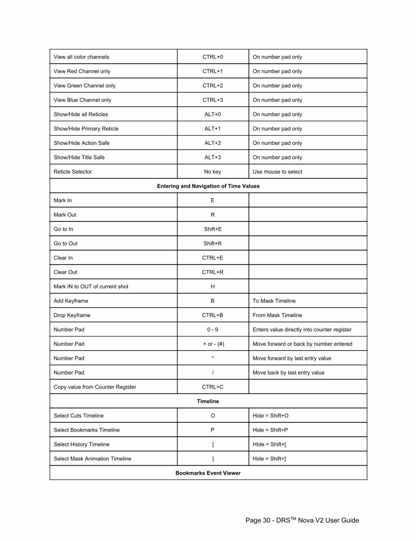
View all color channels CTRL+0 On number pad only
View Red Channel only CTRL+1 On number pad only
View Green Channel only CTRL+2 On number pad only
View Blue Channel only CTRL+3 On number pad only
Show/Hide all Reticles ALT+0 On number pad only
Show/Hide Primary Reticle ALT+1 On number pad only
Show/Hide Action Safe ALT+2 On number pad only
Show/Hide Title Safe ALT+3 On number pad only
Reticle Selector No key Use mouse to select
Entering and Navigation of Time Values
Mark In E
Mark Out R
Go to In Shift+E
Go to Out Shift+R
Clear In CTRL+E
Clear Out CTRL+R
Mark IN to OUT of current shot H
Add Keyframe B To Mask Timeline
Drop Keyframe CTRL+B From Mask Timeline
Number Pad 0 9 Enters value directly into counter register
Number Pad + or (#) Move forward or back by number entered
Number Pad * Move forward by last entry value
Number Pad / Move back by last entry value
Copy value from Counter Register CTRL+C
Timeline
Select Cuts Timeline O Hide = Shift+O
Select Bookmarks Timeline P Hide = Shift+P
Select History Timeline [ HIde = Shift+[
Select Mask Animation Timeline ] Hide = Shift+]
Bookmarks Event Viewer
Page 30 DRSTM Nova V2 User Guide
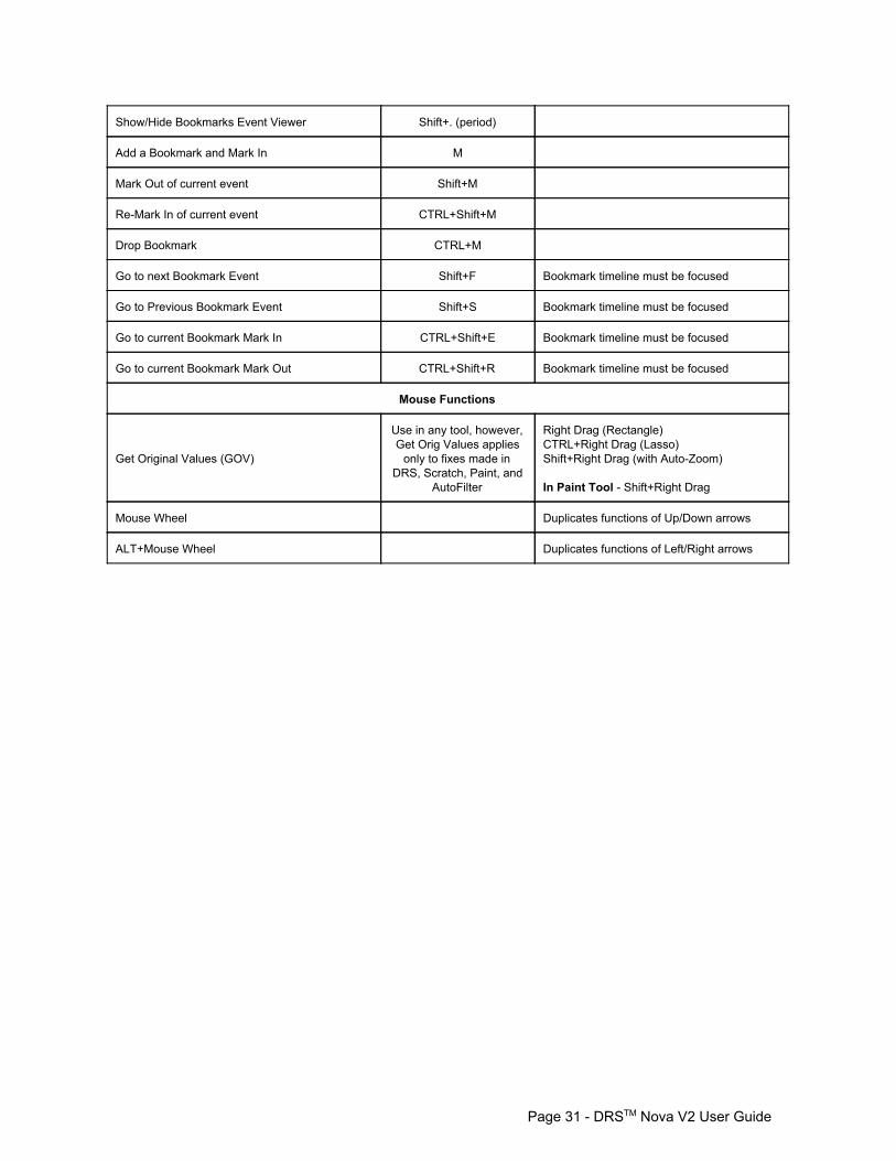
Show/Hide Bookmarks Event Viewer Shift+. (period)
Add a Bookmark and Mark In M
Mark Out of current event Shift+M
ReMark In of current event CTRL+Shift+M
Drop Bookmark CTRL+M
Go to next Bookmark Event Shift+F Bookmark timeline must be focused
Go to Previous Bookmark Event Shift+S Bookmark timeline must be focused
Go to current Bookmark Mark In CTRL+Shift+E Bookmark timeline must be focused
Go to current Bookmark Mark Out CTRL+Shift+R Bookmark timeline must be focused
Mouse Functions
Get Original Values (GOV)
Use in any tool, however, Get Orig Values applies only to fixes made in
DRS, Scratch, Paint, and AutoFilter
Right Drag (Rectangle) CTRL+Right Drag (Lasso) Shift+Right Drag (with AutoZoom) In Paint Tool Shift+Right Drag
Mouse Wheel Duplicates functions of Up/Down arrows
ALT+Mouse Wheel Duplicates functions of Left/Right arrows
Page 31 DRSTM Nova V2 User Guide
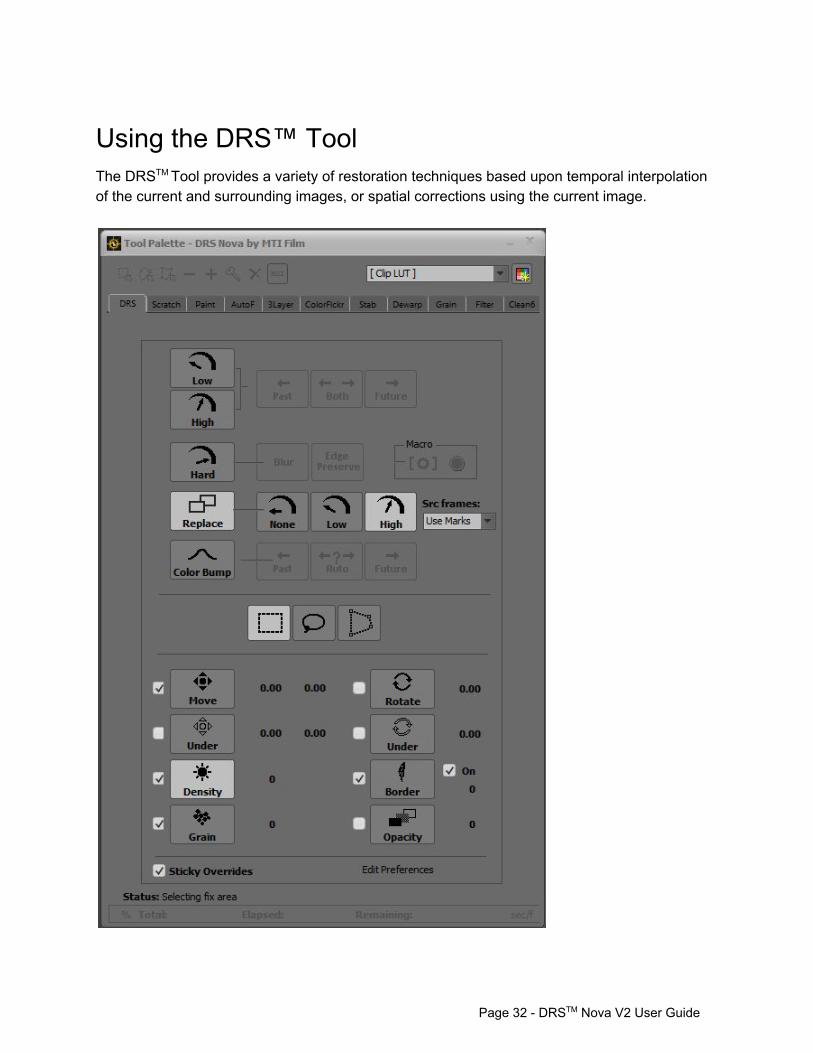
Using the DRS™ Tool The DRSTM Tool provides a variety of restoration techniques based upon temporal interpolation of the current and surrounding images, or spatial corrections using the current image.
Page 32 DRSTM Nova V2 User Guide

DRS™ has five modes of operation: 1. Low Motion 2. High Motion 3. Hard Motion 4. Replace 5. Color Bump
Each mode has “Overrides”; adjustments that can be made to the operation. The Overrides are:
a. Move Over/Under b. Rotate Over/Under c. Density d. Border e. Grain f. Opacity
Overrides can persist through a series of fixes if the Sticky Overrides checkbox is enabled. This is useful when a combination of Overrides contribute to make the result of a fix applicable to other fixes requiring the same result. If you do not want the Overrides to persist from one fix to another, uncheck the Sticky Overrides checkbox found at the bottom of the tool. The DRS™ Tool provides three different types of drawing tools.
a. Rectangle b. Lasso c. Bezier
Pressing the Q key will toggle through the drawing tools in succession. Or you can click directly on the corresponding buttons. Low and High Motion. These modes of operation offer three temporal options to calculate fixes:
a. Past – uses previous frames b. Both – uses previous and succeeding frames c. Future – uses succeeding frames
The difference between Low and High modes is that the High mode uses a wider “search area” to calculate its fix. You should experiment with both modes to see which does the best job for the problem at hand. To select Low Motion press the 1 key or click on the corresponding button. Pressing the 1 key repeatedly will cycle through the three temporal options. To select High Motion press the 2 key or click on the corresponding button. Pressing the 2 key repeatedly will cycle through the three temporal options.
Page 33 DRSTM Nova V2 User Guide

Hard Motion. This mode is used for fixes where temporal corrections are not suitable. For example, if there are extreme fluctuations in density between frames temporal fixes may produce undesirable results. Hard Motion uses spatial correction of the image thus eliminating defects of surrounding frames from the correction.
Hint: Hard Motion should only be used on small fixes since it inherently must blur the picture. Adding a small amount of grain to match the surrounding grain is also advised. There are two options for Hard Motion.
a. Blur – where the image is blurred concentrically toward the middle of the fix. b. Edge Preserve – where the edges of the subject image are preserved.
To select Hard Motion press the 3 key or click on the corresponding button. Pressing the 3 key repeatedly will toggle through the two options. Replace. This mode “borrows” pixels from source frames using 3 motion choices.
The Source Frames dropdown field selects which source frames will be used as follows: 1. Use Marks (default selection)
a. From the Mark IN if no Mark Out is present b. From the Mark OUT if no Mark In is present c. From the Marks IN and OUT if both are present
2. Prev 1 From the previous frame only 3. Prev 2 From the previous two frames only 4. Next 1 From the next frame only 5. Next 2 From the next two frames only 6. Prev & Next From the previous and next frame only
To select Replace press the 4 key or click on the corresponding button. Pressing the 4 key repeatedly will cycle through the three temporal options.
Page 34 DRSTM Nova V2 User Guide
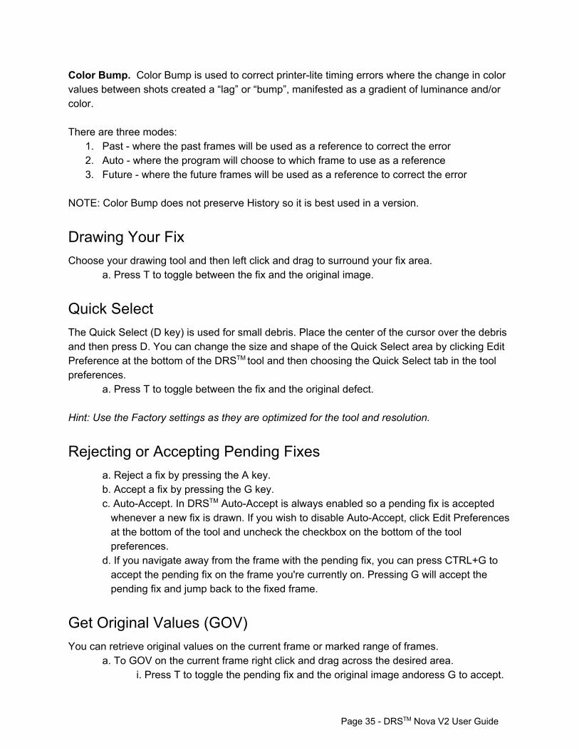
Color Bump. Color Bump is used to correct printerlite timing errors where the change in color values between shots created a “lag” or “bump”, manifested as a gradient of luminance and/or color. There are three modes:
1. Past where the past frames will be used as a reference to correct the error 2. Auto where the program will choose to which frame to use as a reference 3. Future where the future frames will be used as a reference to correct the error
NOTE: Color Bump does not preserve History so it is best used in a version.
Drawing Your Fix Choose your drawing tool and then left click and drag to surround your fix area.
a. Press T to toggle between the fix and the original image.
Quick Select The Quick Select (D key) is used for small debris. Place the center of the cursor over the debris and then press D. You can change the size and shape of the Quick Select area by clicking Edit Preference at the bottom of the DRSTM tool and then choosing the Quick Select tab in the tool preferences.
a. Press T to toggle between the fix and the original defect. Hint: Use the Factory settings as they are optimized for the tool and resolution.
Rejecting or Accepting Pending Fixes a. Reject a fix by pressing the A key. b. Accept a fix by pressing the G key. c. AutoAccept. In DRSTM AutoAccept is always enabled so a pending fix is accepted whenever a new fix is drawn. If you wish to disable AutoAccept, click Edit Preferences at the bottom of the tool and uncheck the checkbox on the bottom of the tool preferences.
d. If you navigate away from the frame with the pending fix, you can press CTRL+G to accept the pending fix on the frame you're currently on. Pressing G will accept the pending fix and jump back to the fixed frame.
Get Original Values (GOV) You can retrieve original values on the current frame or marked range of frames.
a. To GOV on the current frame right click and drag across the desired area. i. Press T to toggle the pending fix and the original image andoress G to accept.
Page 35 DRSTM Nova V2 User Guide
b. To GOV of a marked range of frames, right click and drag across the desired area and then press Shift+G.
Hint: To see the fix areas outlined in blue, press the W key to toggle on the fixes outline. Press W again to toggle off. Hint: To see the original values of a fix, press Shift+W to toggle them on or off. These key functions can be reversed by going to the Preferences window located in the main File menu and disabling the “W shortcut shows blue boxes…” checkbox on the General Tab. REMEMBER TO TOGGLE SLOWLY SINCE THE PROGRAM REQUIRES TIME TO RETRIEVE THE ORIGINAL PIXELS.
Repeat Last Action To repeat the last action on any frame, press the ~ key. This will exactly repeat the last action whether it was a fix or GOV. The paint tool is an exception in that the ~ key will repeat the last paint stroke or macro while shift+~ will repeat the last GOV.
Page 36 DRSTM Nova V2 User Guide
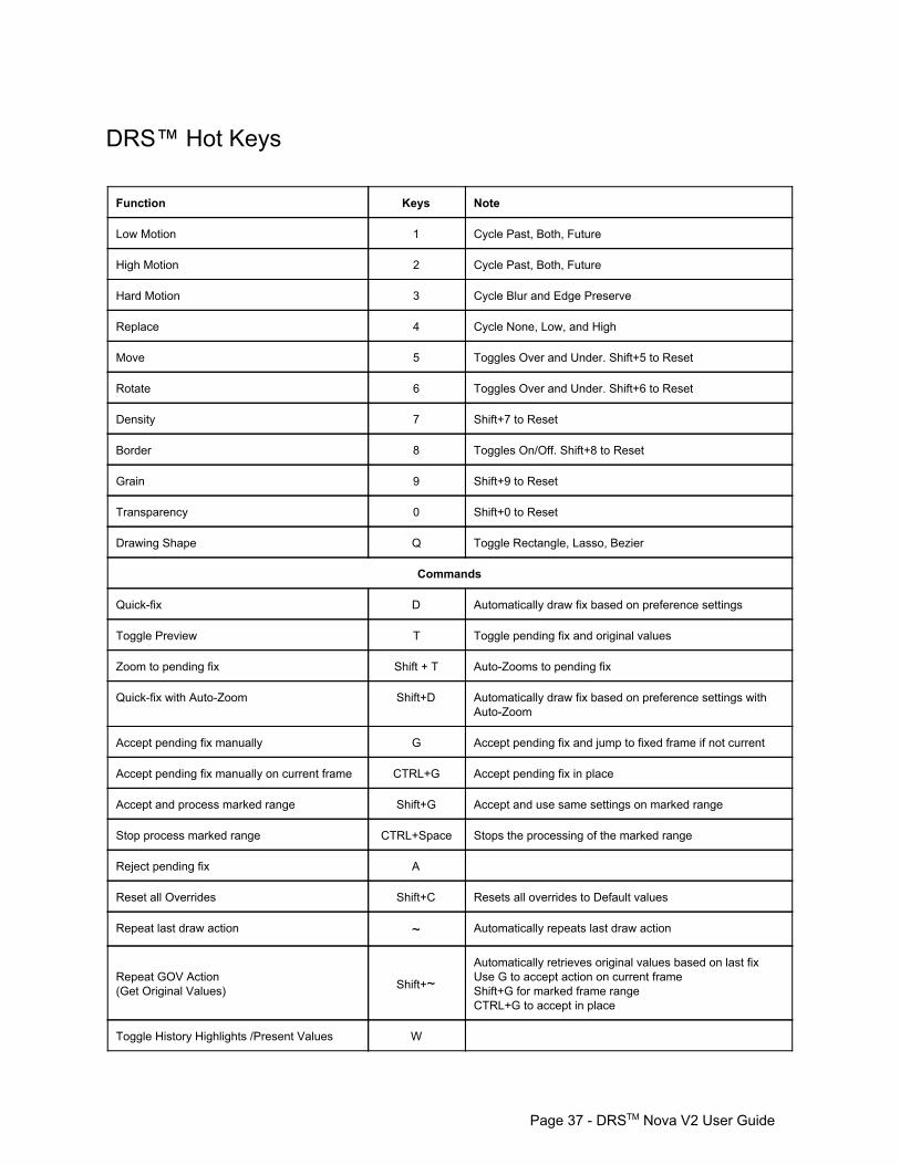
DRS™ Hot Keys Function Keys Note
Low Motion 1 Cycle Past, Both, Future
High Motion 2 Cycle Past, Both, Future
Hard Motion 3 Cycle Blur and Edge Preserve
Replace 4 Cycle None, Low, and High
Move 5 Toggles Over and Under. Shift+5 to Reset
Rotate 6 Toggles Over and Under. Shift+6 to Reset
Density 7 Shift+7 to Reset
Border 8 Toggles On/Off. Shift+8 to Reset
Grain 9 Shift+9 to Reset
Transparency 0 Shift+0 to Reset
Drawing Shape Q Toggle Rectangle, Lasso, Bezier
Commands
Quickfix D Automatically draw fix based on preference settings
Toggle Preview T Toggle pending fix and original values
Zoom to pending fix Shift + T AutoZooms to pending fix
Quickfix with AutoZoom Shift+D Automatically draw fix based on preference settings with AutoZoom
Accept pending fix manually G Accept pending fix and jump to fixed frame if not current
Accept pending fix manually on current frame CTRL+G Accept pending fix in place
Accept and process marked range Shift+G Accept and use same settings on marked range
Stop process marked range CTRL+Space Stops the processing of the marked range
Reject pending fix A
Reset all Overrides Shift+C Resets all overrides to Default values
Repeat last draw action ~ Automatically repeats last draw action
Repeat GOV Action (Get Original Values) Shift+~
Automatically retrieves original values based on last fix Use G to accept action on current frame Shift+G for marked frame range CTRL+G to accept in place
Toggle History Highlights /Present Values W
Page 37 DRSTM Nova V2 User Guide
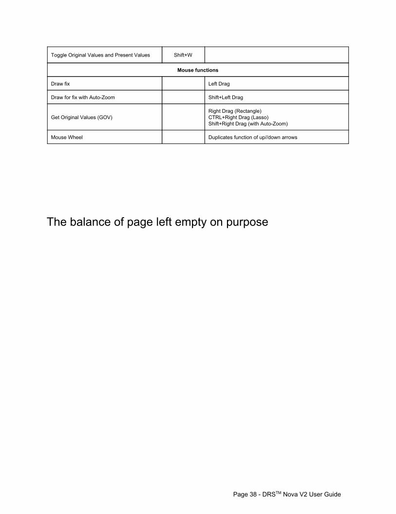
Toggle Original Values and Present Values Shift+W
Mouse functions
Draw fix Left Drag
Draw for fix with AutoZoom Shift+Left Drag
Get Original Values (GOV) Right Drag (Rectangle) CTRL+Right Drag (Lasso) Shift+Right Drag (with AutoZoom)
Mouse Wheel Duplicates function of up//down arrows
The balance of page left empty on purpose
Page 38 DRSTM Nova V2 User Guide
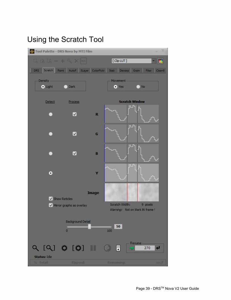
Using the Scratch Tool
Page 39 DRSTM Nova V2 User Guide
Definitions:
Scratch Window The area of the tool that magnifies the scratch properties
Boundary Box The blue rectangle box drawn by the user on the scratch that determines the search area the tool uses to track it over a marked range of frames
Limit Markers Determines the width of the scratch found in the Scratch Window
Magnifier A red reticle rectangle that appears when a Boundary Box is drawn that magnifies the focused area of the scratch in the Scratch Window
1. Establish In and Out marks for processing. 2. Orientation: Is the scratch Vertical or Horizontal? The direction the Boundary Box is
drawn automatically determines its orientation. 3. Density: Is the scratch Light or Dark? Set the contrast of the scratch to help the
algorithm automatically detect the scratch by instructing it to look for light or dark lines. 4. Movement: Is the scratch moving? If so, you must use the Mark In frame as the
reference frame on which you draw the Boundary Box so the tool can track the scratch. The Limit Markers in the Image box will be green indicating that the scratch will be tracked. If Yes and you draw the Boundary Box on a frame other than the Mark In the Limit Markers of the scratch will be red, which means that the tool will not be able to properly track the scratch.
Hint: Leave on Yes at all times. 5. Detect: If desired, select signal to DETECT scratch (Default is Y – luminance). 6. Process: If desired, choose layers to process (Default is all). 7. On Image: Use LEFT mouse button to draw a Boundary Box around scratch. Use
SHIFT while drawing to extend box to limits of frame. Hint 1: Draw box so that only one scratch is included. Hint 2: If there is movement, draw box wide or high enough to include the scratch in all
positions on all frames. After drawing the box a red magnifier will appear.
8. Use LEFT Click on magnifier and drag to position magnifier over scratch. Use SHIFT to constrain movement to one axis. Use CTRL+Click outside the magnifier to jump it to cursor position.
The Limit Markers of the Scratch Window will react to the new position.
9. To define the limits of the scratch you can: a. Mouse Wheel up or down to determine the width b. ALT + Mouse Wheel to move LimitMarkers left or right
OR c. Use LEFT and RIGHT mouse button clicks on either side of scratch.
Page 40 DRSTM Nova V2 User Guide
10. Use BACKGROUND DETAIL slider to preserve detail. 11. Preview or Render one or more frames.
a. To preview the current frame press D or click the Magnifier button located on the bottom of the tool
i. Press T to toggle the pending fix and the original image. ii. Press A to reject the pending fix.
b. To preview the marked frame range press Shift+D or click on the Magnifier with Brackets button on the bottom of the tool
i. Press T to toggle the pending fix and the original image. ii. Press A to reject the pending fix.
c. To render a single frame press G or click the Gear button located on the bottom of the tool
d. To render the marked frame range press Shift+G or click the Gear with Brackets button located on the bottom of the tool
Using the PDL If you wish to set parameters for marked ranges of the clip but want to process them later, you can use the PDL (Process Decision List).
1. Set the parameters for the marked range 2. To create a PDL event, press the , (comma) key or click the PDL button (located at the
bottom of the tool) to create a PDL event 3. When you've added all the events you want to the PDL you can render the PDL by
pressing the Render button on the PDL Viewer window 4. You can also save the PDL for later use or for safety. To save the PDL focus on the
PDL Viewer and press Ctrl+S or click the save icon. Hint: It is not recommended to use the PDL for scratches since each scratch should be corrected with supervision.
Page 41 DRSTM Nova V2 User Guide
Scratch Hot Keys Function Keys Note
Density 1 Toggle Density between Light and Dark
Scratch Width UP/DN Arrows Shift = greater increments, CTRL = less
Mouse Wheel Duplicates function of up/down arrows
Scratch Position LT/RT Arrows Shift = greater increments, CTRL = less
ALT+Mouse Wheel Duplicates function of Left/Right arrows
Preview current frame D Preview fix on current frame
Toggle Preview T Toggle pending fix and original values
Reject pending fix A
Preview marked frame range Shift+D
Render current Frame G
Render marked frame range Shift+G
PDL < Add event to PDL
Show/Hide Boundary Reticles Shift+T
Pause Render Space
Resume Render Space
Stop Render CTRL+Space
Mouse functions
Left Mouse Drag Draw boundary region for fix
Shift+Left Mouse Drag Draw boundary region for fix and automatically extend box to limits of image
Left Click and Drag On Magnifier Locates magnifier
CTRL+Left Click Within Boundary Relocates magnifier
Get Original Values (GOV) Right Drag (Rectangle) CTRL+Right Drag (Lasso)
Mouse Wheel Duplicates function of up/down arrows
ALT Mouse Wheel Duplicates function of Left/Right arrows
Page 42 DRSTM Nova V2 User Guide
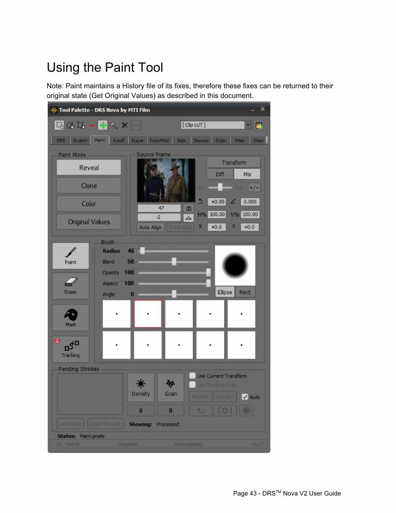
Using the Paint Tool Note: Paint maintains a History file of its fixes, therefore these fixes can be returned to their original state (Get Original Values) as described in this document.
Page 43 DRSTM Nova V2 User Guide
There are four modes of operation in the Paint Tool.
1. Reveal Mode. Allows you to “reveal” a Source Frame to the Target Frame (the frame you’re working on) through paint strokes. The Source Frame can be the same as the Target or another user defined frame.
2. Clone Mode. Allows you to clone, through paint strokes, a portion of a Source Frame to the Target Frame based upon a user defined point of reference. The Source Frame can be the same as the Target or another user defined frame.
3. Color Mode. Allows you to use your paint brush to draw color(s) onto the Target Frame. You can also sample colors through the Eye Dropper, and “drop” color into an area of the Target Frame with the Paint Bucket.
4. Original Values Mode. Allows you to paint the original pixels from the frame History with brush strokes.
Reveal Mode (press 1 or click on the Reveal button)
1. Choose a Source Frame. There are 3 ways to select your Source Frame a. Hold down Ctrl+Shift and use the S and F keys to step. (recommended) b. Type the frame number into the Source Frame’s Frame Number field. c. Type an Offset (in + or frames) in the Source Frame’s Frame Offset field.
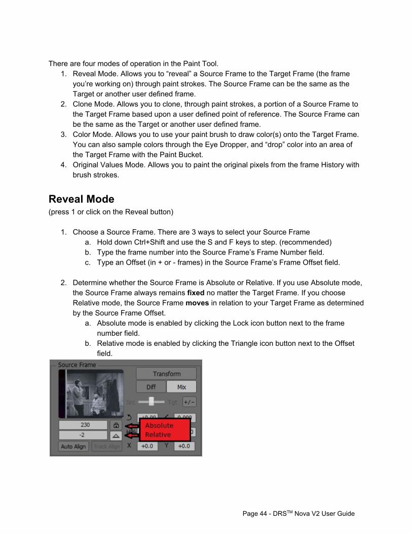
2. Determine whether the Source Frame is Absolute or Relative. If you use Absolute mode,
the Source Frame always remains fixed no matter the Target Frame. If you choose Relative mode, the Source Frame moves in relation to your Target Frame as determined by the Source Frame Offset.
a. Absolute mode is enabled by clicking the Lock icon button next to the frame number field.
b. Relative mode is enabled by clicking the Triangle icon button next to the Offset field.
Page 44 DRSTM Nova V2 User Guide
3. Transform the Source Frame. You may wish to alter the Source Frame in order to align it to the Target Frame. There are two modes of Transform in Paint, Transform and Quick Transform. Transform mode provides the ability to change the geometry of the Source Frame in addition to moving it on X, Y, and Z axes. The Quick Transform mode provides movement of the Source Frame on X and Y axes only.
Enter the Transform mode by pressing the 5 key or clicking the Transform button. a. Determine whether you wish to see a Difference (onionskin) or Mix of the
combined images. i. Press the 6 key, or click the Diff or Mix buttons.
b. Use the yellow Transform Box to alter the Source Frame. i. Click on one of the vertices of the Transform Box and move it as desired. ii. Hold the Shift key down and use a corner vertex to maintain aspect ratio
during resize. iii. Click in the box to move the Source Frame on X and Y axes. iv. Click outside the box to rotate the Source Frame on its Z axis. v. Press CTRL+Shift+C to reset all axes to default.
c. Use Auto Align to align objects in the source and target frames automatically. (If you wish to go directly to Auto Align bypassing Transform, press Shift+5 or ALT+Q)
i. The cursor will change to a square with target hairs ii. Use the mouse wheel to alter the size of the square to include the two
objects that you wish to align iii. Click and the objects will align. If you wish to return to Paint mode directly
after invoking Auto Align, press Shift+Click Hint: Before going into Auto Align mode, use Quick Transform or Transform to move the reference frame in relation to the target frame so that the alignment points are close to each other. Enter the Quick Transform mode by pressing and holding down the ALT key.
a. Leftclick and drag on the image to move the Source frame on the X and Y axes. To enter Auto Align while in Quick Transform, press the Q key, click to align the objects, and then release the ALT key to return to Reveal Mode.
4. Select a paintbrush. a. Click on the desired brush b. Select a round or rectangular shape for the brush. Press the Ellipse or Rect
button c. Use the mouse wheel or slider to alter the brush. Use Shift for greater increments
or CTRL for smaller. i. Radius press D ii. Blend press 8 iii. Opacity press 0
Page 45 DRSTM Nova V2 User Guide
iv. Aspect press – v. Angle press =
5. Paint or Erase
a. Paint i. Left click on the image and draw your stroke(s) ii. Press T to toggle the pending stroke(s) and the original image
b. Erase Pending Strokes i. Right click on the image and draw ii. If you wish to use the Left Mouse button click on the Erase button iii. Press T to toggle the pending stroke(s) and the original image
If no pending strokes are present, a right click and drag will Get Original Values
6. Modify the stroke set a. Use Density and Grain overrides to modify the stroke set.
Density – press 7 or click the button Grain – press 9 or click the button
7. Rejecting or Accepting Pending Strokes
a. Reject a stroke by pressing the A key or clicking the Undo Last button. b. Reject all strokes by pressing Shift+A, or clicking the Reject button in the
Completion Area. c. Accept a stroke set by pressing the G key or clicking the Accept button in the
Completion Area. d. Autoaccept. With Autoaccept enabled all pending strokes are accepted when
the frame count position is changed and a new stroke is made. 8. Instant Macro. As a stroke set is made, the Paint Tool automatically records the set into an Instant Macro function that allows you to recall the stroke set by pressing the repeat key (~).
a. To repeat the macro on a single frame, press the ~ key or click on the Arrow icon in the Macro area.
b. To repeat the macro on a marked frame range, press the ~ key or press the Arrow icon (which recalls the stroke set) and then press Shift+G or press the Render icon (gear bounded by brackets) in the Macro area.
c. If a frame range is marked, executing paint strokes on any frame will render just those frames marked.
Clone Mode (press 2 or click on the Clone button)
1. Choose a Source Frame. There are 3 ways to select your Source Frame a. Hold down CTRL+Shift and use the S or F keys to step.
Page 46 DRSTM Nova V2 User Guide
b. Type the frame number into the Source Frame’s Frame Number field. c. Type an Offset (in frames) in the Source Frame’s Frame Offset field.
2. Determine whether the Source Frame is Absolute or Relative. If you use Absolute mode,
the Source Frame always remains fixed no matter the Target Frame. If you choose Relative mode, the Source Frame moves in relation to your Target Frame as determined by the Source Frame Offset.
a. Absolute mode is enabled by clicking the Lock icon button next to the frame number field.
b. Relative mode is enabled by clicking the Triangle icon button next to the Offset field.
3. Choose your clone point. Press and hold down CTRL+Shift and then click on the point from which you want to clone. The red clone brush will jump to your point. While holding CTRL+Shift, you may also click on the red clone brush and move it to your desired position.
a. Release the CTRL+Shift keys. The clone point is now selected. 4. Select a paintbrush
a. Click on the desired brush b. Select a round or rectangular shape brush by pressing the Ellipse or Rect button. c. Use the mouse wheel or slider to alter the brush. Shift for greater, Ctrl for smaller
increments. i. Radius – press D ii. Blend – press 8 iii. Opacity – press 0 iv. Aspect – press – v. Angle – press =
5. Paint or Erase
a. Paint i. Left click on the image and draw your stroke(s) ii. Press T to toggle the pending stroke(s) and the original image
b. Erase Pending Strokes i. Right click on the image and draw
If you wish to use the Left Mouse button click on the Erase button i. Press T to toggle the pending stroke(s) and the original image
If no pending strokes are present, a right click and drag will Get Original Values 6. Modify the stroke set
a. Use Density and Grain overrides to modify the stroke set. i. Density – press 7 or click the button ii. Grain – press 9 or click the button
Page 47 DRSTM Nova V2 User Guide

7. Rejecting or Accepting Pending Strokes a. Reject a stroke by pressing the A key or clicking the Undo Last button. a. Reject all strokes by pressing Shift+A, or clicking the Reject button in the
Completion Area. b. Accept a stroke set by pressing the G key or clicking the Accept button in the
Completion Area. c. Autoaccept. With Autoaccept enabled all pending strokes are accepted when
the frame count position is changed and a new stroke is made. 8. Instant Macro. As a stroke set is made, the Paint Tool automatically records the set into an Instant Macro function that allows you to recall the stroke set by pressing the repeat key (~).
a. To repeat the macro on a single frame, press the ~ key or click on the Arrow icon in the Macro area.
b. To repeat the macro on a marked frame range, press the ~ key or press the Arrow icon (which recalls the stroke set) and then press Shift+G or press the Render icon (gear bounded by brackets) in the Macro area.
c. If a frame range is marked, executing paint strokes on any frame will render just those frames marked.
Color Mode (press 3 or click on the Color button) 1. Pick a color from the color palette. 2. Select a paintbrush
a. Click on the desired brush b. Select a round or rectangular shape brush by pressing the Ellipse or Rect button. c. Use the mouse wheel or slider to alter the brush. Shift for greater, Ctrl for smaller
increments. i. Radius press D ii. Blend press 8 iii. Opacity press 0 iv. Aspect press – v. Angle press =
3. Paint or Erase a. Paint
i. Left click on the image and draw your stroke(s) ii. Press T to toggle the pending stroke(s) and the original image
b. Erase Pending Strokes i. Right click on the image and draw ii. If you wish to use the Left Mouse button click on the Erase button iii. Press T to toggle the pending stroke(s) and the original image
Page 48 DRSTM Nova V2 User Guide
If no pending strokes are present, a right click and drag will Get Original Values
4. Modify the stroke set
a. Use Density and Grain overrides to modify the stroke set. i. Density press 7 or click the button ii. Grain press 9 or click the button
5. Rejecting or Accepting Pending Strokes
a. Reject a stroke by pressing the A key or clicking the Undo Last button. b. Reject all strokes by pressing Shift+A, or clicking the Reject button in the
Completion Area. c. Accept a stroke set by pressing the G key or clicking the Accept button in the
Completion Area. d. Autoaccept. With Autoaccept enabled all pending strokes are accepted when
the frame count position is changed and a new stroke is made.
6. Instant Macro. As a stroke set is made, the Paint Tool automatically records the set into an Instant Macro function that allows you to recall the stroke set by pressing the repeat key (~).
a. To repeat the macro on a single frame, press the ~ key or click on the Arrow icon in the Macro area.
b. To repeat the macro on a marked frame range, press the ~ key or press the Arrow icon (which recalls the stroke set) and then press Shift+G or press the Render icon (gear bounded by brackets) in the Macro area.
c. If a frame range is marked, executing paint strokes on any frame will render just those frames marked.
7. Use the Eye Dropper to sample a color from the image.
a. Press and hold down Ctrl+Shift to turn the brush into an Eye Dropper or click on the Eye Dropper button.
8. Use the Bucket to drop color into the image. a. Press Alt once to enter into Bucket mode or click on the Bucket button. b. Click on the image. c. Use the Tolerance slider to adjust the number of affected pixels. d. Press Alt again to exit Bucket mode.
i. Press T to toggle the pending stroke(s) and the original image.
Original Values Mode (press 4 or click on the Original Values button) 1. Select a paintbrush
a. Click on the desired brush
Page 49 DRSTM Nova V2 User Guide
b. Select a round or rectangular shape brush by pressing the Ellipse or Rect button. c. Use the mouse wheel or slider to alter the brush. Shift for greater, Ctrl for smaller
increments. i. Radius press D ii. Blend press 8 iii. Opacity press 0 iv. Aspect press – v. Angle press =
2. Paint or Erase a. Paint
i. Left click on the image and draw your stroke(s) ii. Press T to toggle the pending stroke(s) and the original image
b. Erase Pending Strokes i. Right click on the image and draw ii. If you wish to use the Left Mouse button click on the Erase button iii. Press T to toggle the pending stroke(s) and the original image
If no pending strokes are present, a right click and drag will Get Original Values 3. Modify the stroke set
a. Use Density and Grain overrides to modify the stroke set. i. Density – press 7 or click the button ii. Grain – press 9 or click the button
4. Rejecting or Accepting Pending Strokes
a. Reject a stroke by pressing the A key or clicking the Undo Last button. b. Reject all strokes by pressing Shift+A, or clicking the Reject button in the
Completion Area. c. Accept a stroke set by pressing the G key or clicking the Accept button in the
Completion Area. d. Autoaccept. With Autoaccept enabled all pending strokes are accepted when
the frame count position is changed and a new stroke is made. 5. Instant Macro. As a stroke set is made, the Paint Tool automatically records the set into an Instant Macro function that allows you to recall the stroke set by pressing the repeat key (~).
a. To repeat the macro on a single frame, press the ~ key or click on the Arrow icon in the Macro area.
b. To repeat the macro on a marked frame range, press the ~ key or press the Arrow icon (which recalls the stroke set) and then press Shift+G or press the Render icon (gear bounded by brackets) in the Macro area.
c. If a frame range is marked, executing paint strokes on any frame will render just those frames marked.
Page 50 DRSTM Nova V2 User Guide
Get Original Values (GOV) The right mouse button will GOV if there are no Pending Strokes present. To GOV using a rectangle, right click and drag. To GOV using a lasso, press CTRL+Right click and drag and then release the mouse button near the begin point to complete the lasso Once a GOV stroke is complete, you can repeat it by pressing the ~ key.
Using Mask in the Paint Tool Unlike other tools that use Mask, which only require that Mask is enabled, Paint requires that the Mask mode be invoked. This is due to the fact that the mouse is used for both brushes and Mask drawing tools. Entering Mask Mode (3 ways)
1. Press Shfit+4 2. Press Ctrl+I 3. Click the Mask button
You can enter Mask mode directly from Reveal, Clone, and Color Modes. You can also enter the Mask mode while in Transform.
Paint Hot Keys Function Keys Note
Choose Reference Frame CTRL+Shift Use navigation keys to choose reference frame displayed while holding down CTRL+Shift
Reveal Mode 1
Set Source Frame = Target Frame CTRL+Shift+Space
Clone Mode 2
Clone Mode – Choose reference point
CTRL+Shift+Click
Color Mode 3
Color Mode – Color Picker CTRL+Shift+Click
Color Mode – Paint Bucket ALT+Click
Original Values Mode 4
Mask Mode Shift+4
Page 51 DRSTM Nova V2 User Guide
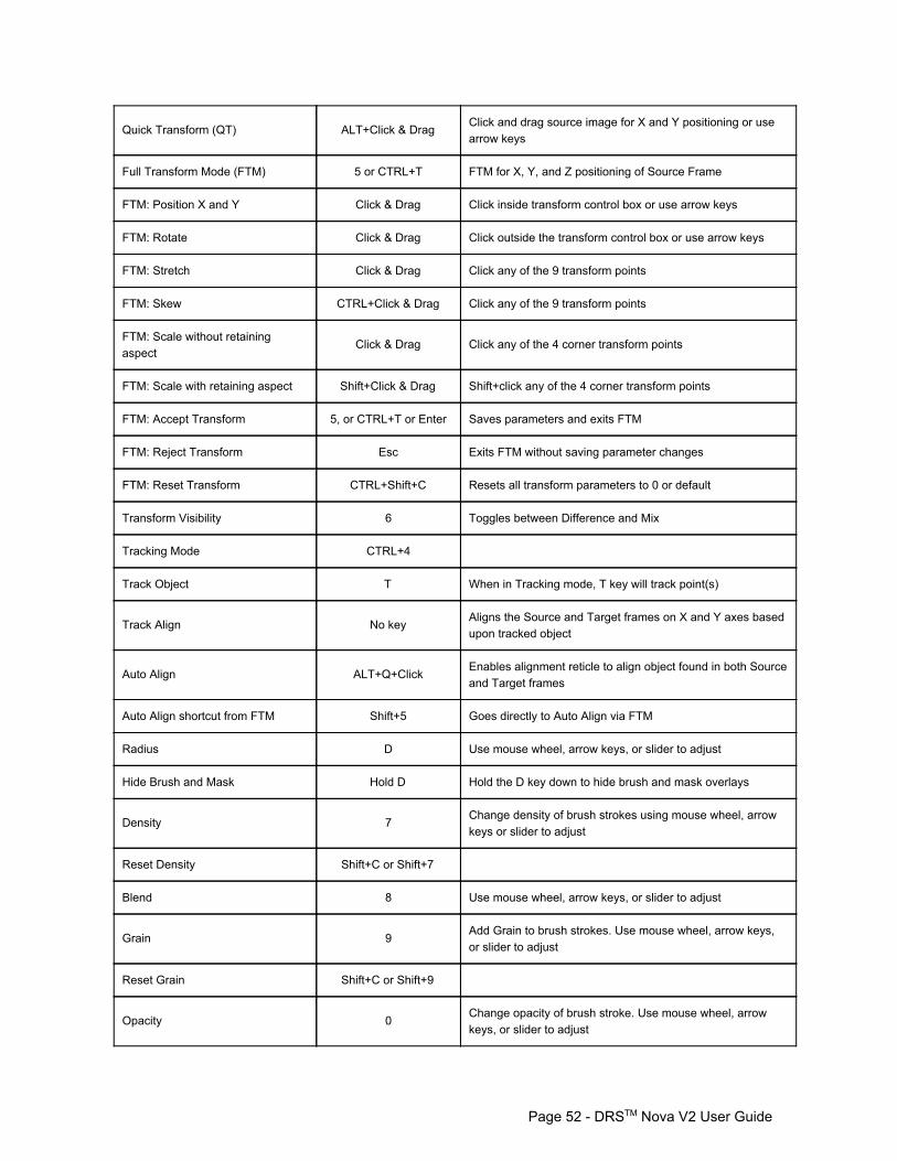
Quick Transform (QT) ALT+Click & Drag Click and drag source image for X and Y positioning or use arrow keys
Full Transform Mode (FTM) 5 or CTRL+T FTM for X, Y, and Z positioning of Source Frame
FTM: Position X and Y Click & Drag Click inside transform control box or use arrow keys
FTM: Rotate Click & Drag Click outside the transform control box or use arrow keys
FTM: Stretch Click & Drag Click any of the 9 transform points
FTM: Skew CTRL+Click & Drag Click any of the 9 transform points
FTM: Scale without retaining aspect
Click & Drag Click any of the 4 corner transform points
FTM: Scale with retaining aspect Shift+Click & Drag Shift+click any of the 4 corner transform points
FTM: Accept Transform 5, or CTRL+T or Enter Saves parameters and exits FTM
FTM: Reject Transform Esc Exits FTM without saving parameter changes
FTM: Reset Transform CTRL+Shift+C Resets all transform parameters to 0 or default
Transform Visibility 6 Toggles between Difference and Mix
Tracking Mode CTRL+4
Track Object T When in Tracking mode, T key will track point(s)
Track Align No key Aligns the Source and Target frames on X and Y axes based upon tracked object
Auto Align ALT+Q+Click Enables alignment reticle to align object found in both Source and Target frames
Auto Align shortcut from FTM Shift+5 Goes directly to Auto Align via FTM
Radius D Use mouse wheel, arrow keys, or slider to adjust
Hide Brush and Mask Hold D Hold the D key down to hide brush and mask overlays
Density 7 Change density of brush strokes using mouse wheel, arrow keys or slider to adjust
Reset Density Shift+C or Shift+7
Blend 8 Use mouse wheel, arrow keys, or slider to adjust
Grain 9 Add Grain to brush strokes. Use mouse wheel, arrow keys, or slider to adjust
Reset Grain Shift+C or Shift+9
Opacity 0 Change opacity of brush stroke. Use mouse wheel, arrow keys, or slider to adjust
Page 52 DRSTM Nova V2 User Guide

Aspect Change aspect of brush stroke. Use mouse wheel, arrow keys, or slider to adjust
Angle = Change angle of brush stoke. Use mouse wheel, arrow keys, or slider to adjust
Select Brush No key Click on Brush
Reject last stroke A
Reject all strokes Shift+A
Commands
Toggle pending stroke(s) and original
T
Accept manually G Accept pending fix and jump to fixed frame if not current
Accept in place CTRL+G Accept pending fix in place
Accept and render marked range Shift+G
Repeat last action ~ Repeats last stroke(s) or GOV action
Repeat last action and render range
~+Shift+G Repeats last stroke(s) or GOV action and renders marked range
Abort Render CTRL+Space
Accept and render marked range Shift+G
Mouse functions
Get Original Values (GOV) Right Drag (Rectangle) CTRL+Right Drag (Lasso)
Mouse Wheel Adjust focused slider
Mouse Wheel in Transform Up and Down Moves Source Frame up and down – use Shift for greater increments, CTRL for less
Mouse Wheel in Transform ALT Moves Source Frame left and right – use Shift for greater increments, CTRL for less
AutoAccept is always functional when enabled. Any subsequent action will accept pending strokes
Use G to accept action on current frame
Shift+G to accept action for marked frame range
CTRL+G to accept action in place
Use Shift for greater increments, CTRL for less on all sliders
Page 53 DRSTM Nova V2 User Guide
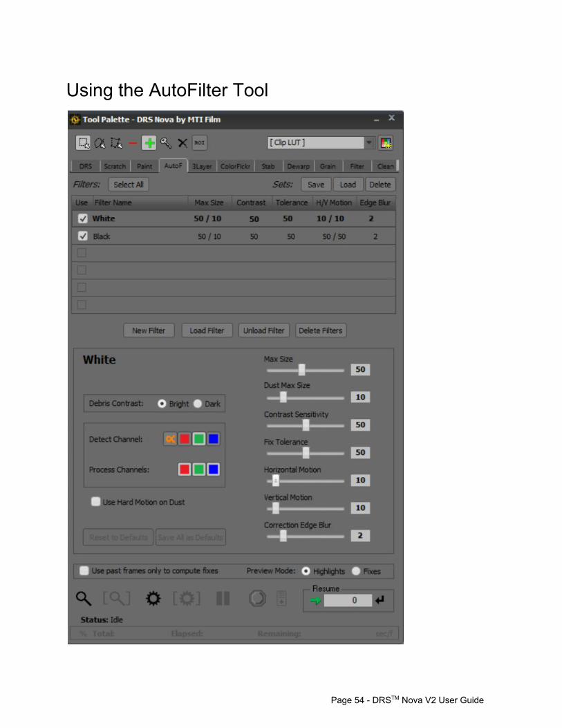
Using the AutoFilter Tool
Page 54 DRSTM Nova V2 User Guide

AutoFilter is a flexible and powerful tool for identifying and removing different types of debris. There are a number of parameters that impact the effectiveness of the tool, designed to assist the user in identifying particular types of debris. While AutoFilter is an automated tool, the better it is understood the better the result. For the automation to work, it must be able to discern when an object in the frame is foreign to the original photography. To do this properly, AutoFilter must analyze every frame and compare them to their surrounding neighbors. Along with the settings you assign to the various parameters, the results can assist in reducing the number of hours spent manually “picking” dirt.
ROI Mode A creative use of ROI mode (Region of Interest) in AutoFilter can facilitate dirt cleanup on a frame by frame basis. For example when in ROI Mode a Leftclick/drag drawn region serves as a quick way to surround several pieces of debris at once and replace only the pixels required to eliminate the offending dirt. To enter ROI mode press Shift+Q or click the ROI button on the Tool Palette. Since AutoFilter maintains a History file of its fixes, these fixes can be returned to their original state (Get Original Values) using a Right click/drag over the area you wish to retrieve.
Filter Sets A Filter Set is a group of filters that are designed to work together. Use the 'Load' button in the upperright next to “Sets:” drop down field to choose a filter set. There, by default, you will find three Filter Sets.
a. Normal: White and Black Debris i. White
Debris Contrast: Bright Detect: Green Channel Process: All Channels
ii. Black Debris Contrast: Dark Detect: Green Channel Process: All Channels
(Note: the green channel is used by default to detect this dirt because it generally has the strongest signal)
b. 3 layer Separation. For debris to be found on individual color channels. i. Red
Debris Contrast: Bright Detect: Red Channel Process: All Channels
Page 55 DRSTM Nova V2 User Guide
ii. Green
Debris Contrast: Bright Detect: Green Channel Process: All Channels
iii. Blue Debris Contrast: Bright Detect: Blue Channel Process: All Channels
iv. Red/Dark Debris Contrast: Dark Detect: Red Channel Process: All Channels
v. Green/Dark Debris Contrast: Dark Detect: Green Channel Process: All Channels
vi. Blue/Dark Debris Contrast: Dark Detect: Blue Channel Process: All Channels
Note: for 3 layer filters, each detects on a single channel, but the default setting still processes (corrects) all channels to account for any crosschannel bleed after successive prints.
c. AlphaFilter. This filter allows for using the Alpha Channel to determine where corrections to be applied to the image. This requires that the alpha channel contain this information, which usually comes from a film scanner.
i. Alpha Debris Contrast: Bright Detect: Alpha Channel Process: All Channels
Parameters Parameters are set for each filter separately or together if multiple filters are selected. In order to adjust parameters, you must click on a filter found in the Filters box at the top of the tool. You may select multiple filters using CTRL+Click and Shift+Click. The Highlighted filters are displayed with bold text with a dark grey border. Below, in the Parameters area, you will find a variety of filter adjustments. Experiment with the parameters of each slider to determine their best use for the debris you wish to detect.
Page 56 DRSTM Nova V2 User Guide
1. Max Size. Use the slider to determine the maximum size of the debris you wish to identify with the selected filter. Only debris smaller than the max size will be processed.
2. Dust Max Size. This determines the maximum size of a debris to be classified as dust.
All 'dust' is processed, regardless of whether the fix quality meets the min fix confidence (see below)
3. Contrast Sensitivity. Determines the least amount of contrast the debris must have in
comparison to the surrounding image in order to be detected by the filter. Higher numbers will detect more debris.
4. Fix Tolerance. Potential fixes for detected debris, according to the size and contrast
parameters, are evaluated and must be under the Fix Tolerance threshold in order to be applied. Higher numbers for this parameter are more aggressive, as the tool will be more flexible in the replacements it allows.
5. Horizontal and Vertical Motion. Determines the search area (as a percentage of the
frame) that the filter will use to find a suitable replacement for the fix. Motion Hint: Use a low setting (5) for animation shot on twos, and a higher setting (10) for live action.
6. Correction Edge Blur. Determines how much the fix will “grow” in order to blur the edges.
7. Use Hard Motion on Dust. Like the DRS Hard Motion option, a spatial blur will be applied to any debris qualifying as Dust. This is useful in circumstances where there is extreme motion.
8. Use past frames to compute fixes. Very useful for fixing small sized dirt found on
animation cells that were shot on “2s”. Since the general algorithm of AutoFilter looks forward and back to assess whether an object is dirt, this mode forces the algorithm to look back only.
Example Usage Processing AutoFilter on a complete shot or section of shot:
1. Review the shot to see if it should be AutoFiltered. Shots with lots of similar debris and without too much motion are good shots to start with.
2. Stop on a frame that has some debris that you can see easily.
Page 57 DRSTM Nova V2 User Guide
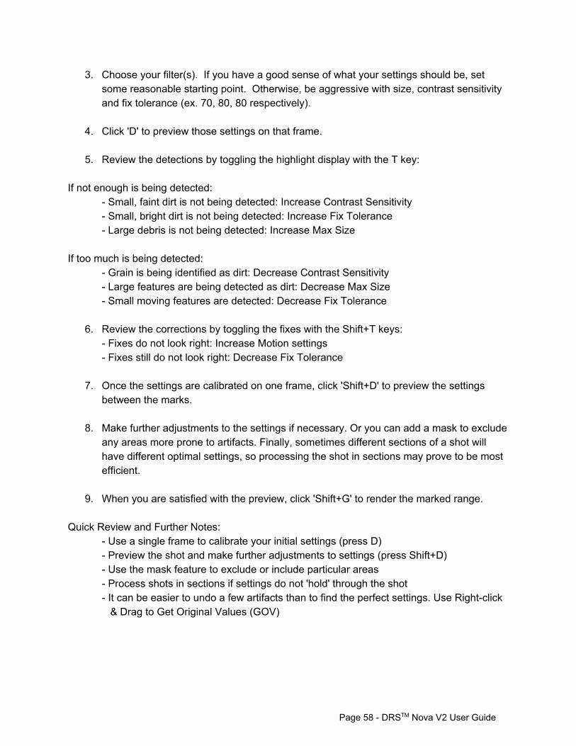
3. Choose your filter(s). If you have a good sense of what your settings should be, set some reasonable starting point. Otherwise, be aggressive with size, contrast sensitivity and fix tolerance (ex. 70, 80, 80 respectively).
4. Click 'D' to preview those settings on that frame.
5. Review the detections by toggling the highlight display with the T key:
If not enough is being detected:
Small, faint dirt is not being detected: Increase Contrast Sensitivity Small, bright dirt is not being detected: Increase Fix Tolerance Large debris is not being detected: Increase Max Size
If too much is being detected:
Grain is being identified as dirt: Decrease Contrast Sensitivity Large features are being detected as dirt: Decrease Max Size Small moving features are detected: Decrease Fix Tolerance
6. Review the corrections by toggling the fixes with the Shift+T keys:
Fixes do not look right: Increase Motion settings Fixes still do not look right: Decrease Fix Tolerance
7. Once the settings are calibrated on one frame, click 'Shift+D' to preview the settings
between the marks.
8. Make further adjustments to the settings if necessary. Or you can add a mask to exclude any areas more prone to artifacts. Finally, sometimes different sections of a shot will have different optimal settings, so processing the shot in sections may prove to be most efficient.
9. When you are satisfied with the preview, click 'Shift+G' to render the marked range.
Quick Review and Further Notes:
Use a single frame to calibrate your initial settings (press D) Preview the shot and make further adjustments to settings (press Shift+D) Use the mask feature to exclude or include particular areas Process shots in sections if settings do not 'hold' through the shot It can be easier to undo a few artifacts than to find the perfect settings. Use Rightclick & Drag to Get Original Values (GOV)
Page 58 DRSTM Nova V2 User Guide
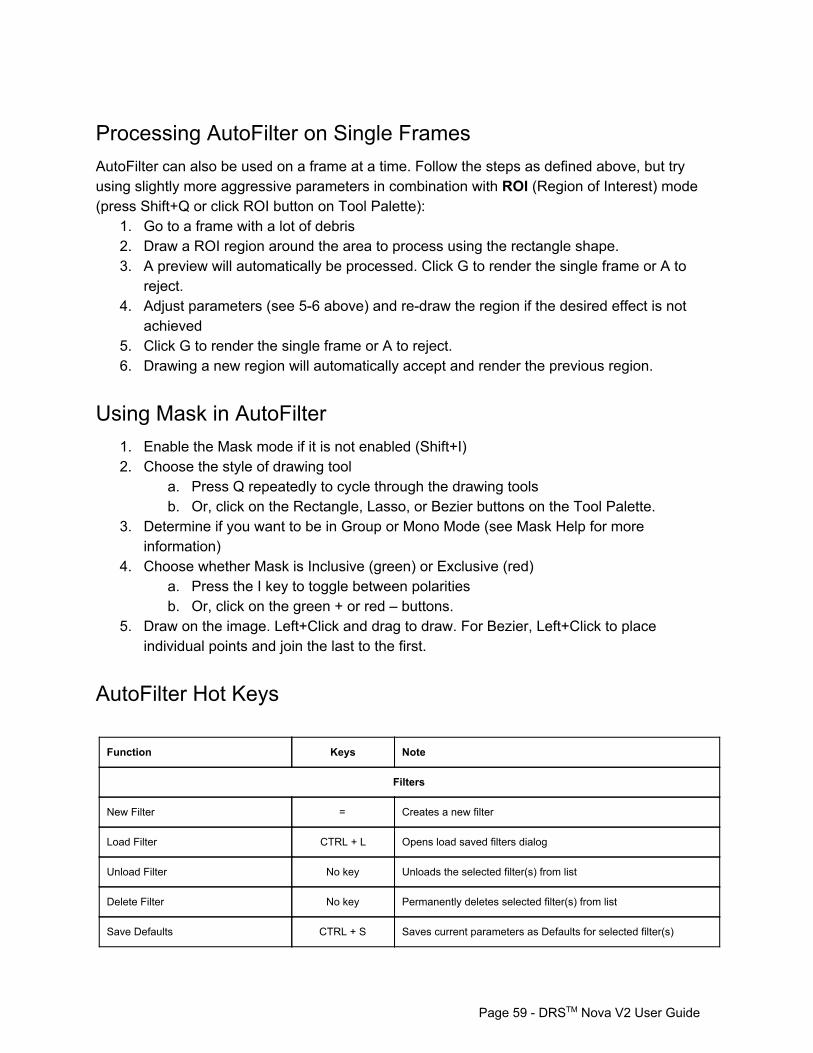
Processing AutoFilter on Single Frames AutoFilter can also be used on a frame at a time. Follow the steps as defined above, but try using slightly more aggressive parameters in combination with ROI (Region of Interest) mode (press Shift+Q or click ROI button on Tool Palette):
1. Go to a frame with a lot of debris 2. Draw a ROI region around the area to process using the rectangle shape. 3. A preview will automatically be processed. Click G to render the single frame or A to
reject. 4. Adjust parameters (see 56 above) and redraw the region if the desired effect is not
achieved 5. Click G to render the single frame or A to reject. 6. Drawing a new region will automatically accept and render the previous region.
Using Mask in AutoFilter 1. Enable the Mask mode if it is not enabled (Shift+I) 2. Choose the style of drawing tool
a. Press Q repeatedly to cycle through the drawing tools b. Or, click on the Rectangle, Lasso, or Bezier buttons on the Tool Palette.
3. Determine if you want to be in Group or Mono Mode (see Mask Help for more information)
4. Choose whether Mask is Inclusive (green) or Exclusive (red) a. Press the I key to toggle between polarities b. Or, click on the green + or red – buttons.
5. Draw on the image. Left+Click and drag to draw. For Bezier, Left+Click to place individual points and join the last to the first.
AutoFilter Hot Keys Function Keys Note
Filters
New Filter = Creates a new filter
Load Filter CTRL + L Opens load saved filters dialog
Unload Filter No key Unloads the selected filter(s) from list
Delete Filter No key Permanently deletes selected filter(s) from list
Save Defaults CTRL + S Saves current parameters as Defaults for selected filter(s)
Page 59 DRSTM Nova V2 User Guide

Reset Grain Shift+C Reset Grain to 0
Reset Filter(s) to Defaults CTRL+Shift + C Resets Default parameters for selected filter(s)
Basic Parameters
Toggle Mask shapes Q
Toggle ROI Mode Shift+Q
Reject pending ROI A
Size 1
Dust Size 2
Contrast 3
Fix Tolerance 4
Horizontal Motion 5
Vertical Motion 6
Correction Edge Blur 7
Grain (press to cycle through options) 9 Shift+9 to reset – use mouse wheel or arrow keys
Toggle Use selected filter 0
Toggle Use Hard Motion on Dust No Key
Toggle Use past frames No Key
Commands
Preview current Frame D
Preview marked frame range Shift+D
Render current Frame G
Render marked frame range Shift+G
PDL < Add event to PDL
Pause Render Space
Resume Render Space
Stop Render CTRL+Space
Display Commands
Toggle Pending Fixes Highlights & Present Values T
Page 60 DRSTM Nova V2 User Guide
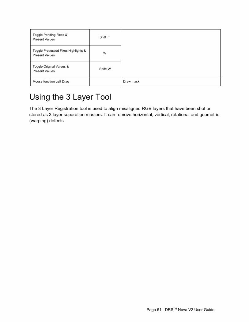
Toggle Pending Fixes & Present Values Shift+T
Toggle Processed Fixes Highlights & Present Values W
Toggle Original Values & Present Values Shift+W
Mouse function Left Drag Draw mask
Using the 3 Layer Tool The 3 Layer Registration tool is used to align misaligned RGB layers that have been shot or stored as 3 layer separation masters. It can remove horizontal, vertical, rotational and geometric (warping) defects.
Page 61 DRSTM Nova V2 User Guide
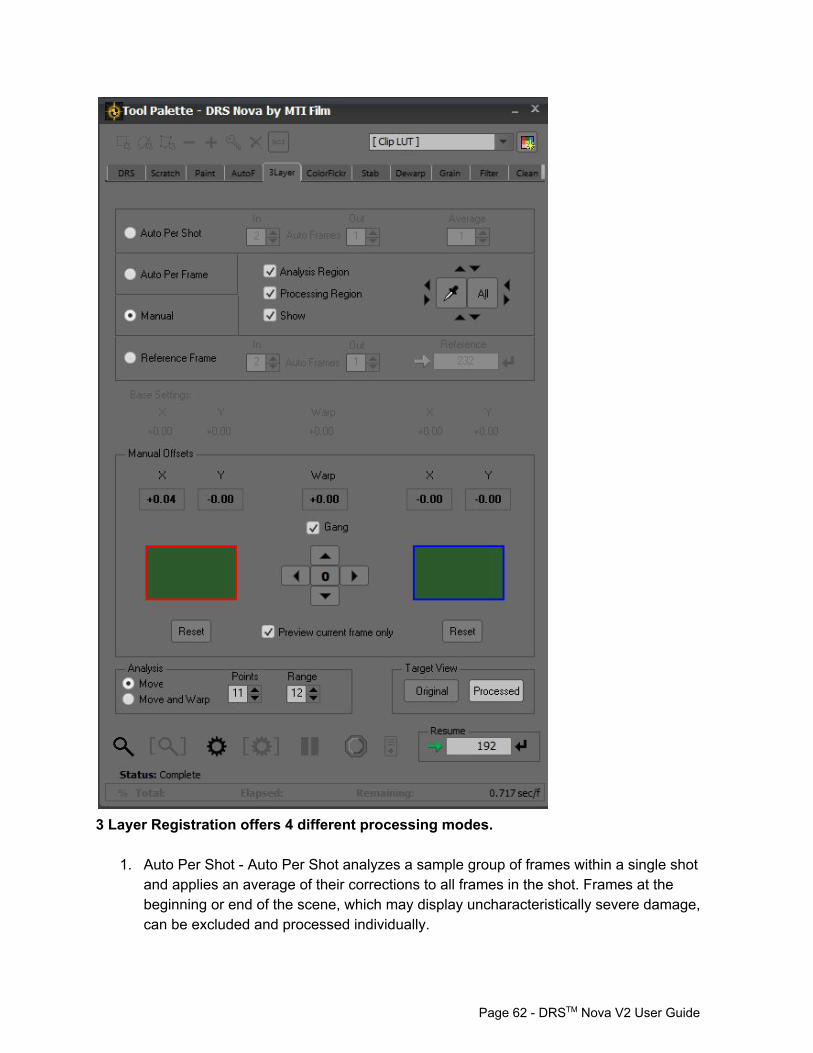
3 Layer Registration offers 4 different processing modes.
1. Auto Per Shot Auto Per Shot analyzes a sample group of frames within a single shot and applies an average of their corrections to all frames in the shot. Frames at the beginning or end of the scene, which may display uncharacteristically severe damage, can be excluded and processed individually.
Page 62 DRSTM Nova V2 User Guide
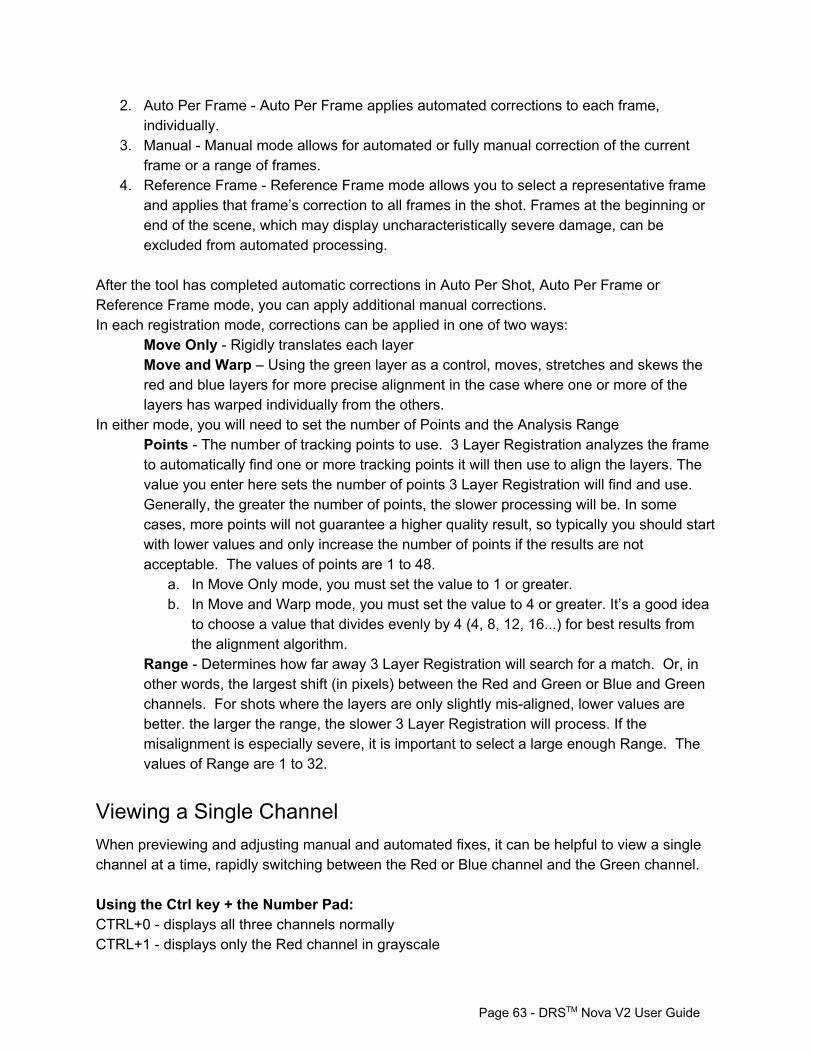
2. Auto Per Frame Auto Per Frame applies automated corrections to each frame, individually.
3. Manual Manual mode allows for automated or fully manual correction of the current frame or a range of frames.
4. Reference Frame Reference Frame mode allows you to select a representative frame and applies that frame’s correction to all frames in the shot. Frames at the beginning or end of the scene, which may display uncharacteristically severe damage, can be excluded from automated processing.
After the tool has completed automatic corrections in Auto Per Shot, Auto Per Frame or Reference Frame mode, you can apply additional manual corrections. In each registration mode, corrections can be applied in one of two ways:
Move Only Rigidly translates each layer Move and Warp – Using the green layer as a control, moves, stretches and skews the red and blue layers for more precise alignment in the case where one or more of the layers has warped individually from the others.
In either mode, you will need to set the number of Points and the Analysis Range Points The number of tracking points to use. 3 Layer Registration analyzes the frame to automatically find one or more tracking points it will then use to align the layers. The value you enter here sets the number of points 3 Layer Registration will find and use. Generally, the greater the number of points, the slower processing will be. In some cases, more points will not guarantee a higher quality result, so typically you should start with lower values and only increase the number of points if the results are not acceptable. The values of points are 1 to 48.
a. In Move Only mode, you must set the value to 1 or greater. b. In Move and Warp mode, you must set the value to 4 or greater. It’s a good idea
to choose a value that divides evenly by 4 (4, 8, 12, 16...) for best results from the alignment algorithm.
Range Determines how far away 3 Layer Registration will search for a match. Or, in other words, the largest shift (in pixels) between the Red and Green or Blue and Green channels. For shots where the layers are only slightly misaligned, lower values are better. the larger the range, the slower 3 Layer Registration will process. If the misalignment is especially severe, it is important to select a large enough Range. The values of Range are 1 to 32.
Viewing a Single Channel When previewing and adjusting manual and automated fixes, it can be helpful to view a single channel at a time, rapidly switching between the Red or Blue channel and the Green channel. Using the Ctrl key + the Number Pad: CTRL+0 displays all three channels normally CTRL+1 displays only the Red channel in grayscale
Page 63 DRSTM Nova V2 User Guide

CTRL+2 displays only the Green channel in grayscale CTRL+3 displays only the Red channel in grayscale
Auto Per Shot Mode 1. Set IN and OUT points 2. Select Auto Per Shot Mode 3. Often, the frames near the scene cut have been damaged more severely that the rest of
the frames and, therefore, should not be included in the average correction applied across the rest of the clip by Auto Per Shot. Set In and Out AutoFrames – AutoFrames allows you to process frames at the beginning and end of the scene separately from the rest of the clip.
a. Set In AutoFrames – the In AutoFrames value sets the number of frames at the beginning of the marked range that will not be processed by Auto Per Shot Mode. Instead, these frames will be processed individually in Auto Per Frame mode. So, if IN AutoFrames is set to 2, the first two frames of the marked range will be processed separately.
b. Set Out AutoFrames – the Out AutoFrames value sets the number of frames at the end of the marked range that will not be processed by Auto Per Shot Mode. Instead, these frames will be processed individually in Auto Per Frame mode. So, if OUT AutoFarmes is set to 2, the last two frames of the marked range will be processed separately
4. Set Average – The Average value sets the number of frames sampled in the marked range to determine the automatic corrections needed.
5. Choose Move Only or Move and Warp Mode 6. Set Points and Range values 7. Preview the automated corrections by pressing the D key (Preview 1) or SHIFT+D
(Preview All). The calculated fix values will be displayed in the Base Settings area. 8. Apply manual corrections on top of the automatic corrections as needed. You can not
change the Base Settings – the final settings will be the Base Settings plus any Manual adjustments.
9. Render the corrections by pressing SHIFT+G
Auto Per Frame Mode 1. Set IN and OUT points 2. Select Auto Per Frame Mode. 3. Choose Move Only or Move and Warp Mode 4. Set Points and Range values 5. Preview the automated corrections by pressing the D key (Preview 1) or SHIFT+D
(Preview All). The calculated fix values will be displayed in the Base Settings area.
Page 64 DRSTM Nova V2 User Guide
6. Apply manual corrections on top of the automatic corrections as needed. You can not change the Base Settings – the final settings will be the Base Settings plus any Manual adjustments.
7. Render the corrections by pressing SHIFT+G
Manual Mode 1. Set IN and OUT points 2. Select Manual Mode 3. Select Layers to Process – 3 Layer Registration uses the Green layer as the base and
aligns the Blue and Red channels to it. 4. Click the Red layer panel (1 key) to toggle selection of the Red layer. 5. Click the Blue layer panel (3 key) to toggle the selection of the Blue layer 6. Check Gang (2 key) to toggle selection of both layers (recommended) 7. Select Move Only or Move and Warp mode 8. Set number of Points and Range 9. Manual mode can do a first automatic pass. To start this process, press Preview 1 (D).
Unlike other modes, the computed values are not placed in Base Settings, but in the editable Manual values area.
10. Use the arrow keys to adjust the positioning of the active layers. You can not change the computed Warp settings manually. The display will update as you make your changes.
11. Render the corrections to the current frame by pressing Render 1 (G) or you can apply the settings across a marked range by pressing Render All (SHIFT+G).
Reference Frame Mode 1. Set IN and OUT points 2. Select Reference Mode 3. Set In and Out AutoFrames – AutoFrames allows you to process frames at the beginning
and end of the scene separately from the rest of the clip. Often, the frames near the scene cut have been damaged more severely that the rest of the frames and so can not be included in the average correction applied across the rest of the clip by Reference.
a. Set In AutoFrames – the In AutoFrames value sets the number of frames at the beginning of the marked range that will not be processed by Reference Mode. Instead, these frames will be processed individually in Auto Per Frame mode. So, if In AutoFrames is set to 2, the first two frames of the marked range will be processed separately
b. Set Out AutoFrames – the Out AutoFrames value sets the number of frames at the end of the marked range that will not be processed by Reference Mode. Instead, these frames will be processed individually in Auto Per Frame mode. So, if Out AutoFarmes is set to 2, the last two frames of the marked range will be processed separately
Page 65 DRSTM Nova V2 User Guide
4. Set Reference frame – 3 Layer Separation will calculate the fix parameters on this frame and then apply those settings across the marked range.
5. Choose Move Only or Move and Warp Mode 6. Set Points and Range values 7. Preview the automated corrections by pressing the D key (Preview 1) or SHIFT+D
(Preview All). The calculated fix values will be displayed in the Base Settings area. 8. Apply manual corrections on top of the automatic corrections as needed. You can not
change the Base Settings – the final settings will be the Base Settings plus any Manual adjustments.
9. Render the corrections by pressing SHIFT+G
Analysis and Processing Region Use the Analysis Region to focus on a particular portion of the frame for the tool to compute adjustments to the layers. When using the Analysis Region the Processing region can be enabled or disabled. If enabled, the processing will be limited to the Analysis Region. If disabled, the whole frame will be processed while the analysis will be limited to the Analysis Region as determined by the blue reticle. To move the reticle, click on the up and down, left and right arrows. To move in greater increments use the Shift key. For smaller increments use the Ctrl key. If there is a black matte around the edges of the picture and you don't want to process the matte, left clicking on the matte using the Eye Dropper will automatically select the picture area excluding the matte. The Eye Dropper can be enabled by either clicking on the button or pressing Ctrl+Shift. The cursor will turn into an Eye Dropper icon.
Using the PDL If you wish to set parameters for marked ranges of the clip but want to process them later, you can use the PDL (Process Decision List).
1. Set the parameters for the marked range 2. To create a PDL event, press the , (comma) key or click the PDL button (located at the
bottom of the tool) to create a PDL event 3. When you've added all the events you want to the PDL you can render the PDL by
pressing the Render button on the PDL Viewer window. 4. You can also save the PDL for later use or for safety. It is recommended that you save
the PDL every 10 events in case of a system stoppage. To save the PDL, place focus on the PDL Viewer and press Ctrl+S or click the save icon.
Page 66 DRSTM Nova V2 User Guide

Apply Correction to Preview Frame Only At times it may be useful to only see the correction on a single frame and not on previous or subsequent ones. If needed, check this box.
3 Layer Hot Keys Function Keys Note
Red Layer 1 Select Red layer for adjustment
Gang Layers 2 Select both Red and Blue layers for adjustment
Blue Layer 3 Select Blue layer for adjustment
Mode Selection 4 Cycles through registration modes
Processing Region On/Off 5
Analysis Mode Selection 6 Cycles between Move Only and Move and Warp modes
Move selected layer(s) Arrow keys Moves selected layer(s) up, down, left and right
Master Reset Shift+C
Commands
Preview current frame D
Toggle Preview T Toggle pending fix and original values
Preview marked frame range Shift+D
Render current frame G
Render marked frame range Shift+G
PDL < Add event to PDL
Page 67 DRSTM Nova V2 User Guide
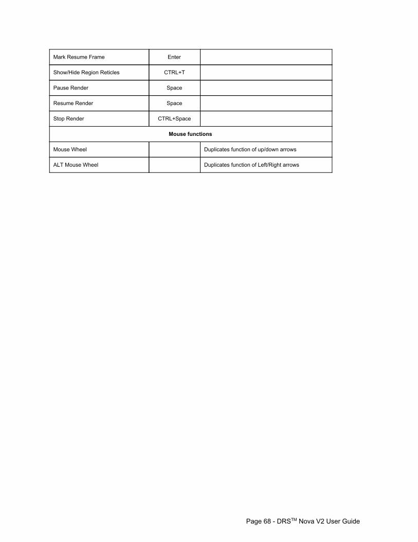
Mark Resume Frame Enter
Show/Hide Region Reticles CTRL+T
Pause Render Space
Resume Render Space
Stop Render CTRL+Space
Mouse functions
Mouse Wheel Duplicates function of up/down arrows
ALT Mouse Wheel Duplicates function of Left/Right arrows
Page 68 DRSTM Nova V2 User Guide
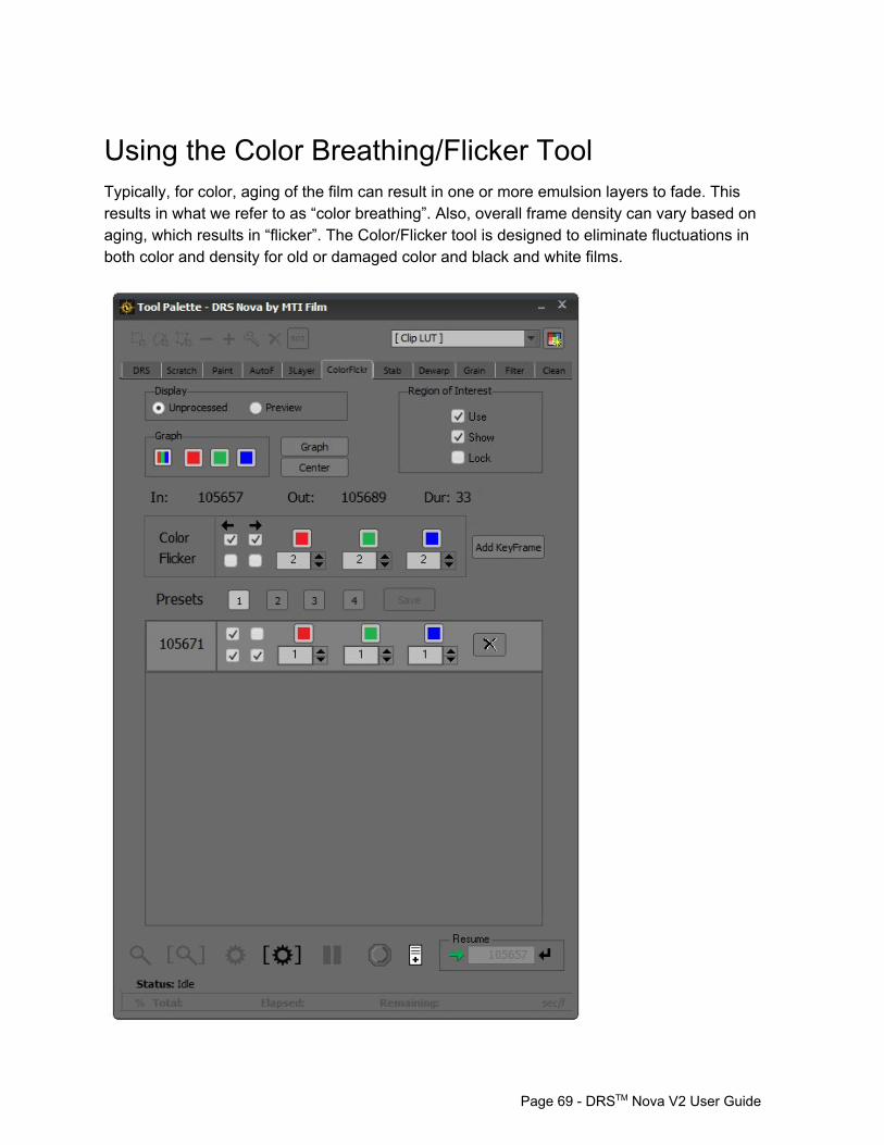
Using the Color Breathing/Flicker Tool Typically, for color, aging of the film can result in one or more emulsion layers to fade. This results in what we refer to as “color breathing”. Also, overall frame density can vary based on aging, which results in “flicker”. The Color/Flicker tool is designed to eliminate fluctuations in both color and density for old or damaged color and black and white films.
Page 69 DRSTM Nova V2 User Guide
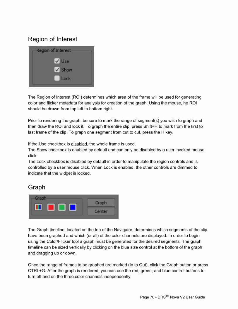
Region of Interest
The Region of Interest (ROI) determines which area of the frame will be used for generating color and flicker metadata for analysis for creation of the graph. Using the mouse, he ROI should be drawn from top left to bottom right. Prior to rendering the graph, be sure to mark the range of segment(s) you wish to graph and then draw the ROI and lock it. To graph the entire clip, press Shift+H to mark from the first to last frame of the clip. To graph one segment from cut to cut, press the H key. If the Use checkbox is disabled, the whole frame is used. The Show checkbox is enabled by default and can only be disabled by a user invoked mouse click. The Lock checkbox is disabled by default in order to manipulate the region controls and is controlled by a user mouse click. When Lock is enabled, the other controls are dimmed to indicate that the widget is locked.
Graph
The Graph timeline, located on the top of the Navigator, determines which segments of the clip have been graphed and which (or all) of the color channels are displayed. In order to begin using the Color/Flicker tool a graph must be generated for the desired segments. The graph timeline can be sized vertically by clicking on the blue size control at the bottom of the graph and dragging up or down. Once the range of frames to be graphed are marked (In to Out), click the Graph button or press CTRL+G. After the graph is rendered, you can use the red, green, and blue control buttons to turn off and on the three color channels independently.
Page 70 DRSTM Nova V2 User Guide
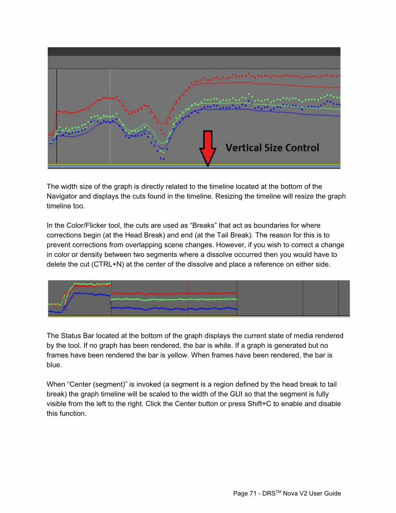
The width size of the graph is directly related to the timeline located at the bottom of the Navigator and displays the cuts found in the timeline. Resizing the timeline will resize the graph timeline too. In the Color/Flicker tool, the cuts are used as “Breaks” that act as boundaries for where corrections begin (at the Head Break) and end (at the Tail Break). The reason for this is to prevent corrections from overlapping scene changes. However, if you wish to correct a change in color or density between two segments where a dissolve occurred then you would have to delete the cut (CTRL+N) at the center of the dissolve and place a reference on either side.
The Status Bar located at the bottom of the graph displays the current state of media rendered by the tool. If no graph has been rendered, the bar is white. If a graph is generated but no frames have been rendered the bar is yellow. When frames have been rendered, the bar is blue. When “Center (segment)” is invoked (a segment is a region defined by the head break to tail break) the graph timeline will be scaled to the width of the GUI so that the segment is fully visible from the left to the right. Click the Center button or press Shift+C to enable and disable this function.
Page 71 DRSTM Nova V2 User Guide
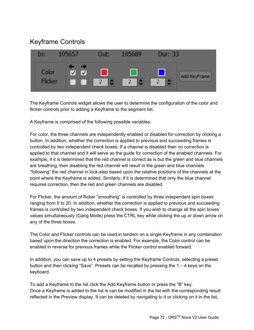
Keyframe Controls
The Keyframe Controls widget allows the user to determine the configuration of the color and flicker controls prior to adding a Keyframe to the segment list. A Keyframe is comprised of the following possible variables: For color, the three channels are independently enabled or disabled for correction by clicking a button. In addition, whether the correction is applied to previous and succeeding frames is controlled by two independent check boxes. If a channel is disabled then no correction is applied to that channel and it will serve as the guide for correction of the enabled channels. For example, if it is determined that the red channel is correct as is but the green and blue channels are breathing, then disabling the red channel will result in the green and blue channels “following” the red channel in lockstep based upon the relative positions of the channels at the point where the Keyframe is added. Similarly, if it is determined that only the blue channel requires correction, then the red and green channels are disabled. For Flicker, the amount of flicker “smoothing” is controlled by three independent spin boxes ranging from 0 to 20. In addition, whether the correction is applied to previous and succeeding frames is controlled by two independent check boxes. If you wish to change all the spin boxes’ values simultaneously (Gang Mode) press the CTRL key while clicking the up or down arrow on any of the three boxes. The Color and Flicker controls can be used in tandem on a single Keyframe in any combination based upon the direction the correction is enabled. For example, the Color control can be enabled in reverse for previous frames while the Flicker control enabled forward. In addition, you can save up to 4 presets by setting the Keyframe Controls, selecting a preset button and then clicking “Save”. Presets can be recalled by pressing the 1 – 4 keys on the keyboard. To add a Keyframe to the list click the Add Keyframe button or press the “B” key. Once a Keyframe is added to the list is can be modified in the list with the corresponding result reflected in the Preview display. It can be deleted by navigating to it or clicking on it in the list,
Page 72 DRSTM Nova V2 User Guide
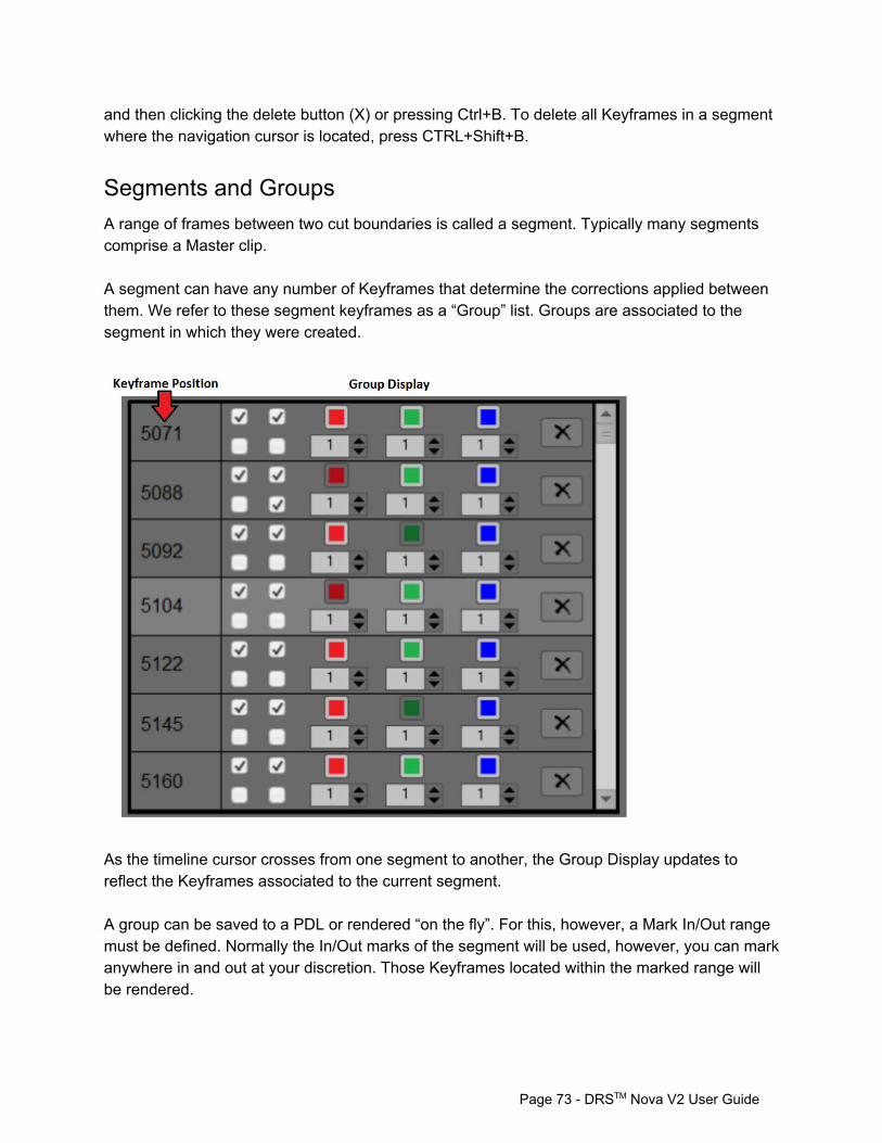
and then clicking the delete button (X) or pressing Ctrl+B. To delete all Keyframes in a segment where the navigation cursor is located, press CTRL+Shift+B.
Segments and Groups A range of frames between two cut boundaries is called a segment. Typically many segments comprise a Master clip. A segment can have any number of Keyframes that determine the corrections applied between them. We refer to these segment keyframes as a “Group” list. Groups are associated to the segment in which they were created.
As the timeline cursor crosses from one segment to another, the Group Display updates to reflect the Keyframes associated to the current segment. A group can be saved to a PDL or rendered “on the fly”. For this, however, a Mark In/Out range must be defined. Normally the In/Out marks of the segment will be used, however, you can mark anywhere in and out at your discretion. Those Keyframes located within the marked range will be rendered.
Page 73 DRSTM Nova V2 User Guide
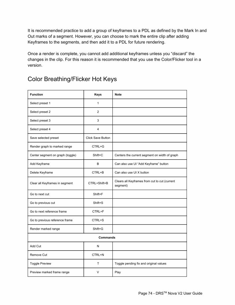
It is recommended practice to add a group of keyframes to a PDL as defined by the Mark In and Out marks of a segment. However, you can choose to mark the entire clip after adding Keyframes to the segments, and then add it to a PDL for future rendering. Once a render is complete, you cannot add additional keyframes unless you “discard” the changes in the clip. For this reason it is recommended that you use the Color/Flicker tool in a version.
Color Breathing/Flicker Hot Keys
Function Keys Note
Select preset 1 1
Select preset 2 2
Select preset 3 3
Select preset 4 4
Save selected preset Click Save Button
Render graph to marked range CTRL+G
Center segment on graph (toggle) Shift+C Centers the current segment on width of graph
Add Keyframe B Can also use UI “Add Keyframe” button
Delete Keyframe CTRL+B Can also use UI X button
Clear all Keyframes in segment CTRL+Shift+B Clears all Keyframes from cut to cut (current segment)
Go to next cut Shift+F
Go to previous cut Shift+S
Go to next reference frame CTRL+F
Go to previous reference frame CTRL+S
Render marked range Shift+G
Commands
Add Cut N
Remove Cut CTRL+N
Toggle Preview T Toggle pending fix and original values
Preview marked frame range V Play
Page 74 DRSTM Nova V2 User Guide

Render marked frame range Shift+G
PDL < Add event to PDL
Use Region of Interest Shift+T
Show/Hide Region Reticles CTRL+T
Lock Region Reticles CTRL+Shift+T
Stop Graph CTRL+Space
Stop Render CTRL+Space
Mouse functions
Draw ROI Left Drag
Page 75 DRSTM Nova V2 User Guide
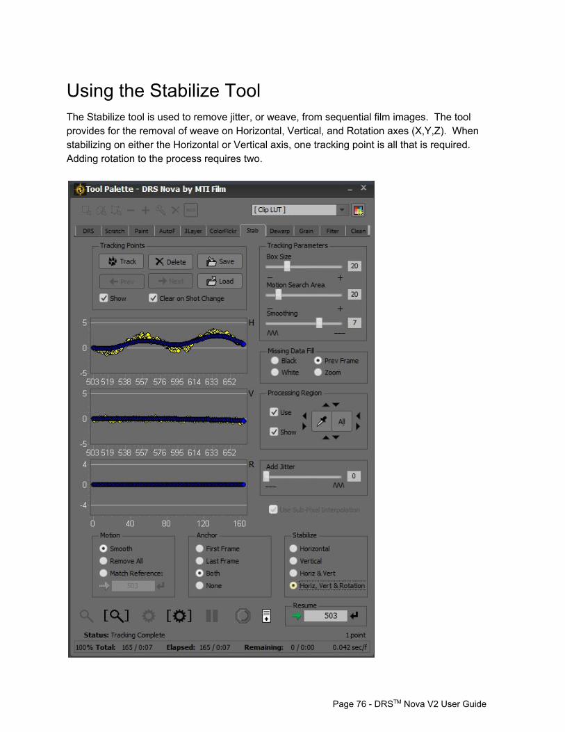
Using the Stabilize Tool The Stabilize tool is used to remove jitter, or weave, from sequential film images. The tool provides for the removal of weave on Horizontal, Vertical, and Rotation axes (X,Y,Z). When stabilizing on either the Horizontal or Vertical axis, one tracking point is all that is required. Adding rotation to the process requires two.
Page 76 DRSTM Nova V2 User Guide
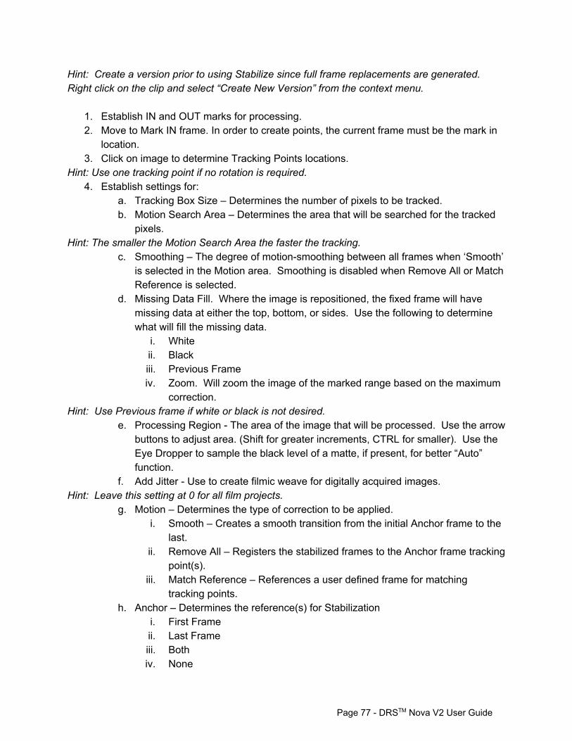
Hint: Create a version prior to using Stabilize since full frame replacements are generated. Right click on the clip and select “Create New Version” from the context menu.
1. Establish IN and OUT marks for processing. 2. Move to Mark IN frame. In order to create points, the current frame must be the mark in
location. 3. Click on image to determine Tracking Points locations.
Hint: Use one tracking point if no rotation is required. 4. Establish settings for:
a. Tracking Box Size – Determines the number of pixels to be tracked. b. Motion Search Area – Determines the area that will be searched for the tracked
pixels. Hint: The smaller the Motion Search Area the faster the tracking.
c. Smoothing – The degree of motionsmoothing between all frames when ‘Smooth’ is selected in the Motion area. Smoothing is disabled when Remove All or Match Reference is selected.
d. Missing Data Fill. Where the image is repositioned, the fixed frame will have missing data at either the top, bottom, or sides. Use the following to determine what will fill the missing data.
i. White ii. Black iii. Previous Frame iv. Zoom. Will zoom the image of the marked range based on the maximum
correction. Hint: Use Previous frame if white or black is not desired.
e. Processing Region The area of the image that will be processed. Use the arrow buttons to adjust area. (Shift for greater increments, CTRL for smaller). Use the Eye Dropper to sample the black level of a matte, if present, for better “Auto” function.
f. Add Jitter Use to create filmic weave for digitally acquired images. Hint: Leave this setting at 0 for all film projects.
g. Motion – Determines the type of correction to be applied. i. Smooth – Creates a smooth transition from the initial Anchor frame to the
last. ii. Remove All – Registers the stabilized frames to the Anchor frame tracking
point(s). iii. Match Reference – References a user defined frame for matching
tracking points. h. Anchor – Determines the reference(s) for Stabilization
i. First Frame ii. Last Frame iii. Both iv. None
Page 77 DRSTM Nova V2 User Guide
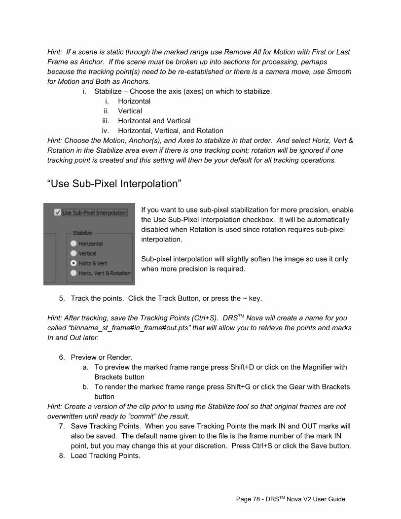
Hint: If a scene is static through the marked range use Remove All for Motion with First or Last Frame as Anchor. If the scene must be broken up into sections for processing, perhaps because the tracking point(s) need to be reestablished or there is a camera move, use Smooth for Motion and Both as Anchors.
i. Stabilize – Choose the axis (axes) on which to stabilize. i. Horizontal ii. Vertical iii. Horizontal and Vertical iv. Horizontal, Vertical, and Rotation
Hint: Choose the Motion, Anchor(s), and Axes to stabilize in that order. And select Horiz, Vert & Rotation in the Stabilize area even if there is one tracking point; rotation will be ignored if one tracking point is created and this setting will then be your default for all tracking operations.
“Use SubPixel Interpolation” If you want to use subpixel stabilization for more precision, enable the Use SubPixel Interpolation checkbox. It will be automatically disabled when Rotation is used since rotation requires subpixel interpolation. Subpixel interpolation will slightly soften the image so use it only when more precision is required.
5. Track the points. Click the Track Button, or press the ~ key. Hint: After tracking, save the Tracking Points (Ctrl+S). DRSTM Nova will create a name for you called “binname_st_frame#in_frame#out.pts” that will allow you to retrieve the points and marks In and Out later.
6. Preview or Render. a. To preview the marked frame range press Shift+D or click on the Magnifier with
Brackets button b. To render the marked frame range press Shift+G or click the Gear with Brackets
button Hint: Create a version of the clip prior to using the Stabilize tool so that original frames are not overwritten until ready to “commit” the result.
7. Save Tracking Points. When you save Tracking Points the mark IN and OUT marks will also be saved. The default name given to the file is the frame number of the mark IN point, but you may change this at your discretion. Press Ctrl+S or click the Save button.
8. Load Tracking Points.
Page 78 DRSTM Nova V2 User Guide

a. Press Ctrl+L or click the Load button. This function loads the Tracking Points and the original mark IN and OUT marks.
b. If you wish to move the marks to a different position simply enter a new IN mark (E key).
c. To load a saved tracking point(s) after marking a new IN point, press Shift+L. The saved tracking points will now be located to the new mark IN.
9. Clear on Shot Change. Tracking points are automatically cleared when a new IN mark is established on a new shot if the shot is bounded by cut markers.
Hint: Disable when attempting to use the same tracking point(s) on a series of shots.
Processing Region Use the Processing Region to restrict the processing of the frame to a region of interest as determined by the blue reticle. If disabled, the whole frame will be processed. To move the reticle, click on the up and down, left and right arrows. To move in greater increments use the Shift key. For smaller increments use the Ctrl key. If there is a black matte around the edges of the picture and you don't want to process the matte, left clicking on the matte using the Eye Dropper will automatically select the picture area excluding the matte. The Eye Dropper can be enabled by either clicking on the button or pressing Ctrl+Shift. The cursor will turn into an Eye Dropper icon.
Using the PDL If you wish to set parameters for marked ranges of the clip but want to process them later, you can use the PDL (Process Decision List).
1. Set the parameters for the marked range 2. To create a PDL event, press the , (comma) key or click the PDL button (located at the
bottom of the tool) to create a PDL event 3. When you've added all the events you want to the PDL you can render the PDL by
pressing the Render button on the PDL Viewer window. 4. You can also save the PDL for later use or for safety. It is recommended that you save
the PDL every 10 events in case of a system stoppage. To save the PDL, place focus on the PDL Viewer and press Ctrl+S or click the save icon.
Page 79 DRSTM Nova V2 User Guide

Stabilization Hot Keys Function Keys Note
Add Tracking Point Click on Image
Save Tracking Points CTRL+S
Load Tracking Points CTRL+L Load Tracking points and original Marks
Load Tracking Points in place Shift+L Load Tracking points on current frame
Delete Selected Tracking Point A Click on Tracking Point to select. Press A
Delete All Tracking Points Shift+A Clears all Tracking Points
Track Object(s) T
Tracking Box Size 1 Use arrow keys or mouse wheel to adjust slider
Motion Search Area 2 Use arrow keys or mouse wheel to adjust slider
Smoothing 3 Use arrow keys or mouse wheel to adjust slider
Missing Data Fill 4 Cycle through options
Toggle Processing Region 5 Toggle Use Processing Region
Add Jitter 6
Cycle Motion options 7 Cycle Smooth and Remove All Shift+7 to reverse
Cycle Anchor options 8 Cycle First, Last, Both Shift+8 to reverse
Cycle Stabilize options 9 Cycle Horz, Vert, H&V, H,V,Rotation Shift+9 to reverse
Toggle Clear on Shot Change 0
Command
Preview marked frame range Shift+D
Render marked frame range Shift+G
Processing Region Dropper CTRL+Shift Use dropper to determine region (for mattes)
PDL < Add event to PDL
Mark Resume Frame Enter
Show/Hide Points Shift+T Toggles Show/Hide Tracking Points
Show/Hide Processing Region CTRL+T Toggles Show/Hide Processing Region
Page 80 DRSTM Nova V2 User Guide
Pause Render Space
Resume Render Space
Stop Render CTRL+Space
Mouse functions
Mouse Wheel Duplicates function of up/down arrows
Using the Dewarp Tool Dewarp provides for the correction of geometric distortions, or warping, induced by either optical or digital malfunctions. A common example of warping is the “frame bump” phenomenon caused when a bad splice or film notch gets caught on the edge of the film gate of a scanning device (such as a telecine or film scanner) as the film passes through it. The resulting distortion causes an apparent geometric distortion over either a portion or all of the image. The normal process for correcting a warping effect is to first judge the number of distorted frames, and to determine how many “Anchor” (or reference) frames will be used to provide “good” geometry information for the Dewarp algorithm to match. The number of Anchor Frames’ can range from 0 to 2 for each the IN and OUT marks. It is recommended to use a value of no more than 1 frame as the Anchor in most cases. Once the IN and OUT marks and the quantity of their Anchor Frames are established, Tracking Points are placed on the frame in locations where the content has the best chance of being tracked. Corners, reflections, or anything that is static within the scene and can be contained in the Tracking Box’s area (even if it is the edge of a chair, for example) have the best chance of providing good tracking data. Generally speaking the more tracking points on a frame the merrier, but experiment to determine the best effect. Finally, when appropriate, use Dewarp in conjunction with Stabilization, DRSTM and Paint for high quality results.
1. Establish IN and OUT marks for processing. 2. Move to Mark IN frame (Shift+E) 3. Click on image to determine Tracking Points locations. 4. Establish settings for:
a. Tracking Box Size – Determines the number of pixels to be tracked. b. Motion Search Area – Determines the area that will be searched for the tracked
pixels. c. Smoothing – The degree of motion smoothing between the all frames. d. Missing Data Fill
Page 81 DRSTM Nova V2 User Guide
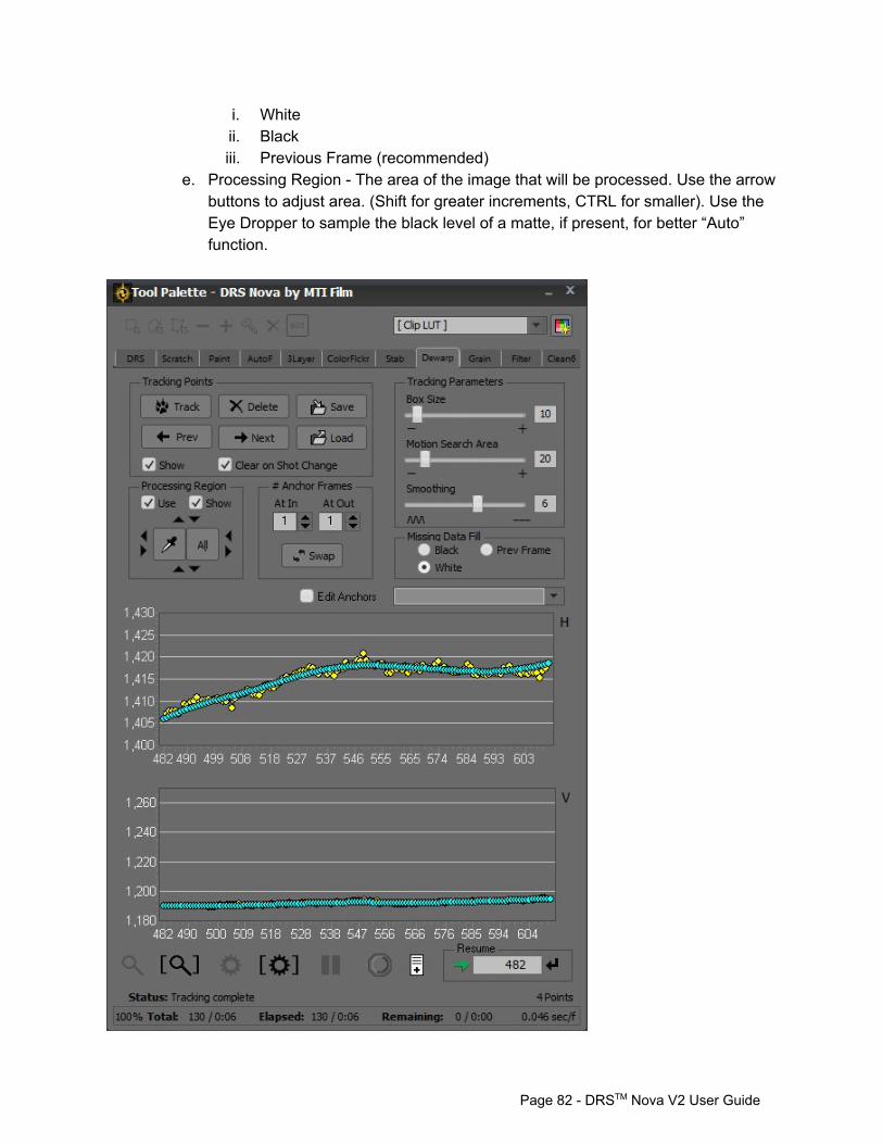
i. White ii. Black iii. Previous Frame (recommended)
e. Processing Region The area of the image that will be processed. Use the arrow buttons to adjust area. (Shift for greater increments, CTRL for smaller). Use the Eye Dropper to sample the black level of a matte, if present, for better “Auto” function.
Page 82 DRSTM Nova V2 User Guide
5. Choose the In and Out Anchor Frames with values from 0 to 2. Anchor frames serve as reference frames for the geometric correction of all frames in between them.
a. Example: A marked duration of 4 frames: i. 0 at the “At In” and 2 at the “At Out” will correct frames 1 and 2, but not
frames 3 and 4. ii. 1 at the “At In” and 1 at the “At Out” will correct frames 2 and 3, but not
frames 1 and 4. Hint: For most dewarping, if the value of the At In or At Out is not 0, a value of 1 is preferable to a value of 2.
6. Track the points. Click the Track Button, or press the ~ key. Hint: After tracking, save the Tracking Points (Ctrl+S)
7. Preview or Render. a. To preview the marked frame range press Shift+D or click on the Magnifier with
Brackets button b. To render the marked frame range press Shift+G or click the Gear with Brackets
button Hint: Create a version of the clip so that original frames are not overwritten until ready to “commit” the result.
8. Save Tracking Points. When you save Tracking Points the mark IN and OUT marks will also be saved. The default name given to the file is the frame number of the mark IN point, and can be changed at your discretion. Press Ctrl+S or click the Save button.
9. Load Tracking Points..
a. Press Ctrl+L or Click the Load button. This function loads the Tracking Points and the original mark IN & OUT marks.
b. If you wish to move the marks to a different position simply enter a new IN mark (E key).
c. You can also load saved Tracking Points to a new frame location by pressing Shift+L or Shift+Load button.
10. Clear on Shot Change. If you wish to clear tracking points on the next shot, enable the check box. If the shot contains similar objects it may be more advantageous to have those tracking points positioned on the new mark in; therefore, disable the check box.
Page 83 DRSTM Nova V2 User Guide
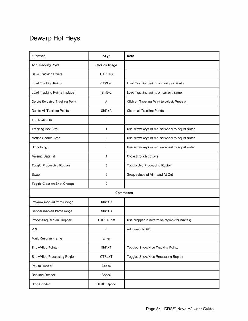
Dewarp Hot Heys Function Keys Note
Add Tracking Point Click on Image
Save Tracking Points CTRL+S
Load Tracking Points CTRL+L Load Tracking points and original Marks
Load Tracking Points in place Shift+L Load Tracking points on current frame
Delete Selected Tracking Point A Click on Tracking Point to select. Press A
Delete All Tracking Points Shift+A Clears all Tracking Points
Track Objects T
Tracking Box Size 1 Use arrow keys or mouse wheel to adjust slider
Motion Search Area 2 Use arrow keys or mouse wheel to adjust slider
Smoothing 3 Use arrow keys or mouse wheel to adjust slider
Missing Data Fill 4 Cycle through options
Toggle Processing Region 5 Toggle Use Processing Region
Swap 6 Swap values of At In and At Out
Toggle Clear on Shot Change 0
Commands
Preview marked frame range Shift+D
Render marked frame range Shift+G
Processing Region Dropper CTRL+Shift Use dropper to determine region (for mattes)
PDL < Add event to PDL
Mark Resume Frame Enter
Show/Hide Points Shift+T Toggles Show/Hide Tracking Points
Show/Hide Processing Region CTRL+T Toggles Show/Hide Processing Region
Pause Render Space
Resume Render Space
Stop Render CTRL+Space
Page 84 DRSTM Nova V2 User Guide
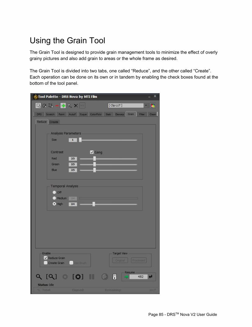
Using the Grain Tool The Grain Tool is designed to provide grain management tools to minimize the effect of overly grainy pictures and also add grain to areas or the whole frame as desired. The Grain Tool is divided into two tabs, one called “Reduce”, and the other called “Create”. Each operation can be done on its own or in tandem by enabling the check boxes found at the bottom of the tool panel.
Page 85 DRSTM Nova V2 User Guide
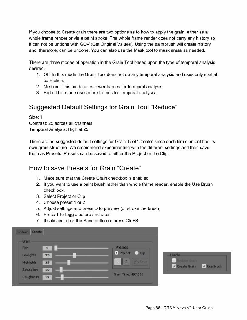
If you choose to Create grain there are two options as to how to apply the grain, either as a whole frame render or via a paint stroke. The whole frame render does not carry any history so it can not be undone with GOV (Get Original Values). Using the paintbrush will create history and, therefore, can be undone. You can also use the Mask tool to mask areas as needed. There are three modes of operation in the Grain Tool based upon the type of temporal analysis desired.
1. Off. In this mode the Grain Tool does not do any temporal analysis and uses only spatial correction.
2. Medium. This mode uses fewer frames for temporal analysis. 3. High. This mode uses more frames for temporal analysis.
Suggested Default Settings for Grain Tool “Reduce” Size: 1 Contrast: 25 across all channels Temporal Analysis: High at 25 There are no suggested default settings for Grain Tool “Create” since each film element has its own grain structure. We recommend experimenting with the different settings and then save them as Presets. Presets can be saved to either the Project or the Clip.
How to save Presets for Grain “Create” 1. Make sure that the Create Grain checkbox is enabled 2. If you want to use a paint brush rather than whole frame render, enable the Use Brush
check box. 3. Select Project or Clip 4. Choose preset 1 or 2 5. Adjust settings and press D to preview (or stroke the brush) 6. Press T to toggle before and after 7. If satisfied, click the Save button or press Ctrl+S
Page 86 DRSTM Nova V2 User Guide
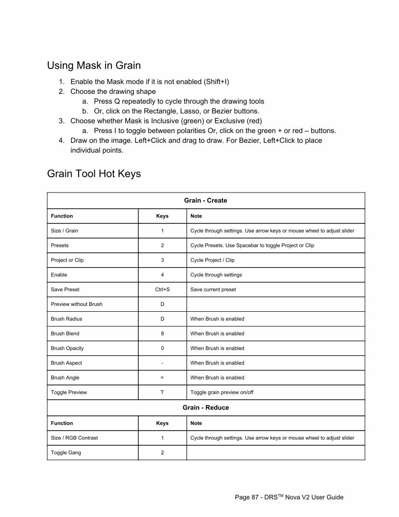
Using Mask in Grain 1. Enable the Mask mode if it is not enabled (Shift+I) 2. Choose the drawing shape
a. Press Q repeatedly to cycle through the drawing tools b. Or, click on the Rectangle, Lasso, or Bezier buttons.
3. Choose whether Mask is Inclusive (green) or Exclusive (red) a. Press I to toggle between polarities Or, click on the green + or red – buttons.
4. Draw on the image. Left+Click and drag to draw. For Bezier, Left+Click to place individual points.
Grain Tool Hot Keys
Grain Create
Function Keys Note
Size / Grain 1 Cycle through settings. Use arrow keys or mouse wheel to adjust slider
Presets 2 Cycle Presets. Use Spacebar to toggle Project or Clip
Project or Clip 3 Cycle Project / Clip
Enable 4 Cycle through settings
Save Preset Ctrl+S Save current preset
Preview without Brush D
Brush Radius D When Brush is enabled
Brush Blend 8 When Brush is enabled
Brush Opacity 0 When Brush is enabled
Brush Aspect When Brush is enabled
Brush Angle = When Brush is enabled
Toggle Preview T Toggle grain preview on/off
Grain Reduce
Function Keys Note
Size / RGB Contrast 1 Cycle through settings. Use arrow keys or mouse wheel to adjust slider
Toggle Gang 2
Page 87 DRSTM Nova V2 User Guide
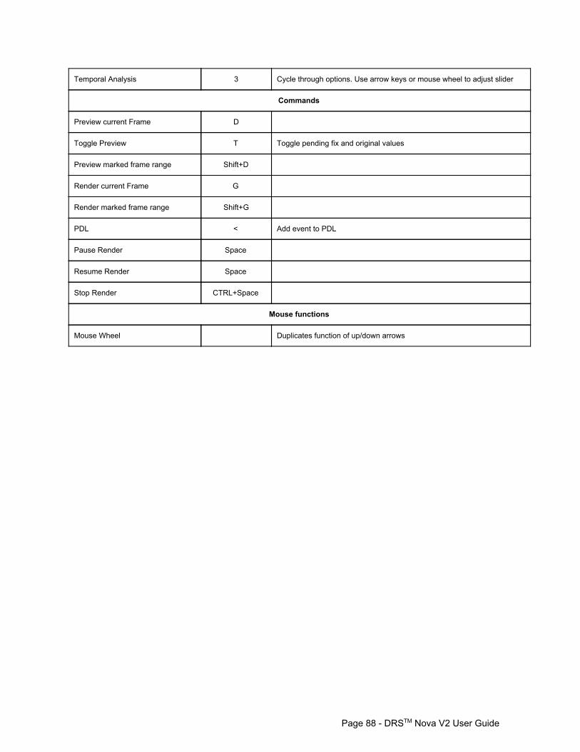
Temporal Analysis 3 Cycle through options. Use arrow keys or mouse wheel to adjust slider
Commands
Preview current Frame D
Toggle Preview T Toggle pending fix and original values
Preview marked frame range Shift+D
Render current Frame G
Render marked frame range Shift+G
PDL < Add event to PDL
Pause Render Space
Resume Render Space
Stop Render CTRL+Space
Mouse functions
Mouse Wheel Duplicates function of up/down arrows
Page 88 DRSTM Nova V2 User Guide
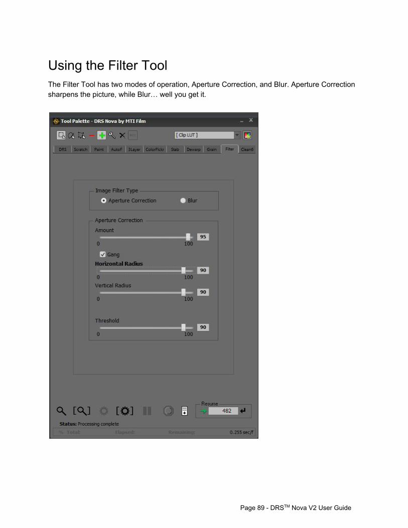
Using the Filter Tool The Filter Tool has two modes of operation, Aperture Correction, and Blur. Aperture Correction sharpens the picture, while Blur… well you get it.
Page 89 DRSTM Nova V2 User Guide
Aperture Correction 1. Press the 1 key to select Aperture Correction. Press the 1 key repeatedly to tab to the
various settings. Press 2 to toggle Gang.
Suggested Setting for Aperture Correction Amount: 70 Horizontal & Vertical Radius: 80 (use Gang mode) Threshold: 90
Blur 1. Press the 3 key to select Blur. Press the 3 key repeatedly to tab to the various settings.
Suggested Settings for Blur Amount: 50 Radius: 50
Using Mask in Filter 1. Enable the Mask mode if it is not enabled (Shift+I) 2. Choose the style of drawing tool
a. Press Q repeatedly to cycle through the drawing shapes b. Or, click on the Rectangle, Lasso, or Bezier buttons.
3. Choose whether Mask is Inclusive (green) or Exclusive (red) a. Press I to toggle between polarities b. Or, click on the green + or red – buttons on the top of the tool palette
4. Draw on the image. Left+Click and drag to draw. For Bezier, Left+Click to place individual points.
Page 90 DRSTM Nova V2 User Guide

Filter Tool Hot Keys Function Keys Note
Aperture Correction 1 Press repeatedly to settings. Use arrow keys or mouse wheel to adjust slider
Toggle Gang 2
Blur 3 Press repeatedly to settings. Use arrow keys or mouse wheel to adjust slider
Commands
Preview current Frame D
Preview marked frame range Shift+D
Render current Frame G
Render marked frame range Shift+G
PDL < Add event to PDL
Mark Resume Frame Enter
Toggle Preview T Toggle original values and pending fix
Pause Render Space
Resume Render Space
Stop Render CTRL+Space
Mouse functions
Mouse Wheel Duplicates function of up/down arrows
Page 91 DRSTM Nova V2 User Guide