
2016 Smart Grid R&D Program Peer Review Meetinge2rg.com/documents/Day one-AM-Web/2016 SG Peer Review...
49
2016 Smart Grid R&D Program Peer Review Meeting Dynamic Reconfigurable Distribution System Implemented Using Advanced Microgrids with Dynamic Boundaries Jianhui Wang Argonne National Laboratory August 16, 2016
Transcript of 2016 Smart Grid R&D Program Peer Review Meetinge2rg.com/documents/Day one-AM-Web/2016 SG Peer Review...

2016 Smart Grid R&D Program
Peer Review Meeting
Dynamic Reconfigurable Distribution System
Implemented Using Advanced Microgrids
with Dynamic Boundaries
Jianhui Wang
Argonne National Laboratory
August 16, 2016
December 2008
Dynamic Reconfigurable Distribution System Implemented Using Advanced Microgrids with Dynamic Boundaries
Objectives & Outcomes
Life-cycle Funding
Summary ($K)
Prior to
FY 16
FY16,
authorized
FY17,
requested
Out-year(s)
N/A $200K $200K
Technical Scope
(Note: The life-cycle funding table above should include all FY funds received and to be requested, from the project beginning year to the project ending year)
2
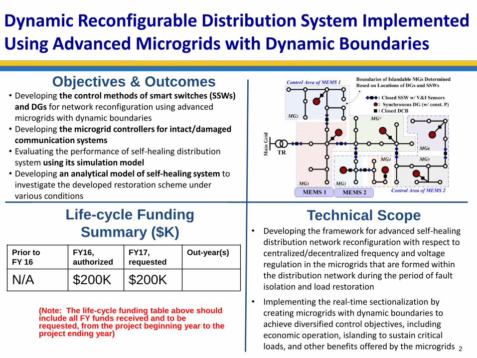
• Developing the control methods of smart switches (SSWs) and DGs for network reconfiguration using advanced microgrids with dynamic boundaries
• Developing the microgrid controllers for intact/damaged communication systems
• Evaluating the performance of self-healing distribution system using its simulation model
• Developing an analytical model of self-healing system to investigate the developed restoration scheme under various conditions
• Developing the framework for advanced self-healing distribution network reconfiguration with respect to centralized/decentralized frequency and voltage regulation in the microgrids that are formed within the distribution network during the period of fault isolation and load restoration
• Implementing the real-time sectionalization by creating microgrids with dynamic boundaries to achieve diversified control objectives, including economic operation, islanding to sustain critical loads, and other benefits offered by the microgrids

December 2008
Dynamic Reconfigurable Distribution Network
3
1. Introduction
a. Previous Approaches for Network Reconfiguration
b. Potential of Commercialized Smart Switches
2. Technology Development and Standard Reconsideration for Implementation of Dynamic Reconfiguration
a. Explanations on Reconfigurable Network Components and Controllers
b. IEEE Standards Related to Islandable Microgrids
3. Control of DGs and Smart Switches for Frequency/Voltage Regulation in Microgrids
4. Future Work : Field Demonstration Project with Eaton Corporation
a. DG Start-up, Frequency/Voltage Regulation, Re-synchronization
b. Frequency Regulation of MGs within a Reconfigurable Distribution System
c. Grid-connected Batteries Participating in MG Frequency Regulation

December 2008
Dynamic Reconfigurable Distribution Network
4
1. Power outages caused by severe weather account for
1) 58% of the total outages since 2002 and 2) 87% of the outages affecting 50,000+ customers.
2. Load de-energized by major wind storms peaks in 15% – 25% of the total outage duration; however many customers still remain without power afterwards.
3. Equipment failure and operator error caused 39.8% of the outages from 1984 to 2006.
Highlighting the importance of advanced network controllers and devices for automatic load restoration
Source: Energy Information Administration Source: NERC
Causes Events
[%] Size
[MW]
Customers [ X103]
Weather (e.g., Earthquake,
Tornado, Hurricane, wind/rain)
44.4 5,841 2,023
Equipment failure 29.7 379 57
Operator error 10.1 489 105
Others* 15.8 2,165 868

December 2008
Previous Studies on Dynamic Network Reconfiguration
5
No. (a) Opt.
Algorithm
(b) Objective Function (c) Operational Constraints (d) DGs
MGs Max
LR Min SO
Min LS
Min PL PF CL VL FL RC CP LP B-
DG NB-DG RES
[3] MIP O O O O O O O O
[4] MIP O O O O O O O
[5] BE O O O O O
[6] GA, PSO O O O O O O O
[7] BE O O O O O O
[8] BB O O O O O O O O O O
[9] GA O O O O O O O O O
[10],[11] GA O O O O O O O
(a) MIP: mixed integer programming, BE: branch exchange, GA: genetic algorithm, PSO: particle swarm optimization, BB: branch and bound, (b) LR: load restored, SO: switching operations, LS: load shed, PL: power loss, (c) PF: power flow, CL: feeder current limit, VL: voltage limit, FL: frequency limit, RC: radial topology constraint, CP: cold load pickup, LP: Load priority, (d) B-DG: black start DG, NB-DG: non-black start DG, RES: renewable energy sources

December 2008
Previous Studies on Dynamic Network Reconfiguration
6
1. Automatic load service restoration aided by NR using MGs becomes an important capability gained by the smart grid: e.g.,
• Self-healing strategies enabling the black-start of micro- turbines within MGs [20]
• Self-healing control actions considering power loss, self-adequacy, and supplied load energy [21]
• An optimal method dividing on-outage network areas into multiple MGs to minimize the operating costs of DERs [22]
2. Research Gap: No Dynamic/Real-Time Analysis of Dynamic Network Reconfiguration
• Optimization algorithms have been adopted to 1) determine one snapshot of the distribution
network topology or 2) change the topologies based on hourly variations in load demand.
• Dynamic effects of line fault, CB operation, and DG interconnection on distribution network
operation (e.g., real-time frequency and voltage regulation in microgrids) were NOT
considered in the previous studies.
• DGs have been modeled as point sources (i.e., PQ/PV nodes) without consideration of
dynamic characteristics of synchronous, induction, or inverter-interfaced machines;
consequently, DG feedback controllers and the connection between DGs and grid-level
controllers were not investigated in the previous NR studies.

December 2008
Smart Switches Improving Self-Healing Capability
7
IntelliRupter PulseCloser Fault Interrupter (S&C Electric Company)
Automatic Switch Control featuring IntelliTeam II (S&C Electric Company)
Automated Feeder Switch (L) & Automated Lateral Switch (R) (Florida Power & Light Co.)
Integrated 3-phase voltage/current sensing on the both sides of SW, providing output signals over the range from load current to fault current.

December 2008
- Full-featured protection relay suitable for a variety of protection applications including feeder protection, reclosing, synch-check, frequency-based load shedding, reverse power, etc.
- The sectionalizer in conjunction with source-side protective devices, such as reclosers or circuit breakers, to automatically isolate faulted sections of distribution systems and reconfigure the network. NOVA Recloser Form 6 Recloser Control
NOVA Sectionalizer
Voltage Regulator
Edison Idea Relays
- Tap-changing autotransformers maintaining voltage within desired limits by controls that feature superior accuracy, reliability, and serviceability.
Smart Switches Improving Self-Healing Capability (cont’d)
Eaton products
December 2008
Technology Development for Dynamic Reconfiguration of Distribution Network
9
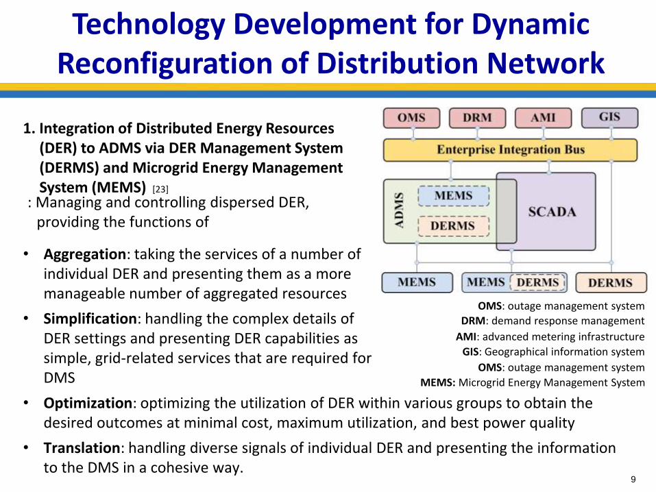
1. Integration of Distributed Energy Resources (DER) to ADMS via DER Management System (DERMS) and Microgrid Energy Management System (MEMS) [23]
: Managing and controlling dispersed DER, providing the functions of
• Optimization: optimizing the utilization of DER within various groups to obtain the desired outcomes at minimal cost, maximum utilization, and best power quality
• Translation: handling diverse signals of individual DER and presenting the information to the DMS in a cohesive way.
DRM: demand response management
OMS: outage management system
AMI: advanced metering infrastructure
GIS: Geographical information system
OMS: outage management system
• Aggregation: taking the services of a number of individual DER and presenting them as a more manageable number of aggregated resources
• Simplification: handling the complex details of DER settings and presenting DER capabilities as simple, grid-related services that are required for DMS MEMS: Microgrid Energy Management System

December 2008
Islandable MGs in Distribution Grid (IEEE Standard 1547.4-2011) Interconnecting DGs to Networks (IEEE Standard 1547.6-2011)
10
In a tradition network, the presence and operation of DGs should NOT cause any NP to
a. Exceed its fault-interrupting capability
b. Separate two dynamic sources
c. Connect two dynamic systems together
d. Operate more frequently than prior to DG operation
- Network protector (NP) : An assembly composed of a
circuit breaker (CB) and its control equipment to
disconnect a transformer from a LV network
DGs should NOT
a. Prevent or delay any NP from opening for faults on the network feeders (i.e., < 50 msec)
b. Delay or prevent NP closure
c. Require the NP settings to be adjusted except by consent of the grid operator
d. Energize a de-energized network
e. Cause an islanding condition within part of a grid network
f. Remain connected to the network if 50% or more of the NPs are open
Possible in Smart-Switch-Based
Self-Healing Distribution Grids
Accommodating DGs

December 2008
Dynamic NR using Synchronous-Machine-Based DGs
11
Main Conditions on Self-Healing, Reconfigurable Distribution System
1. The locations of SSWs and DGs are determined in a scheduling time horizon.
2. Reclosers or fuses are used to disconnect faulted (de-energized) lines from the feeders.
3. Backup DGs, initially used for critical loads within a building, have operated under
normal grid conditions while exporting excess power to other loads on the same or
different feeders [24], [25].
4. The voltage and current sensors on both sides of the SSWs transfer control and
measurement signals to grid management systems (i.e., ADMS, MEMS, and DERMS)
December 2008 12
Dynamic NR using Synchronous-Machine-Based DGs
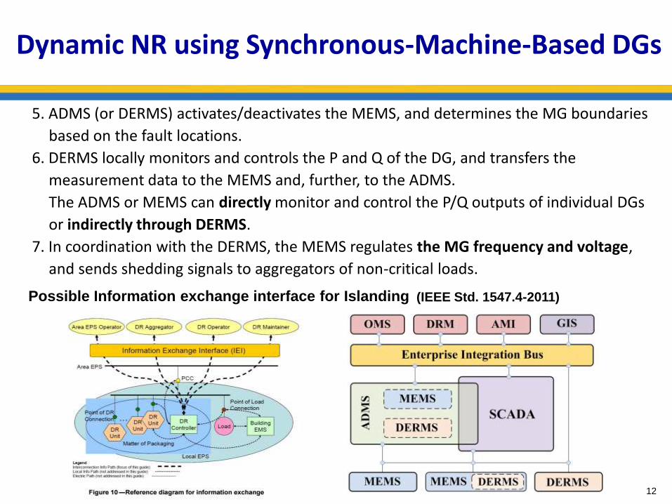
5. ADMS (or DERMS) activates/deactivates the MEMS, and determines the MG boundaries
based on the fault locations.
6. DERMS locally monitors and controls the P and Q of the DG, and transfers the
measurement data to the MEMS and, further, to the ADMS.
The ADMS or MEMS can directly monitor and control the P/Q outputs of individual DGs
or indirectly through DERMS.
7. In coordination with the DERMS, the MEMS regulates the MG frequency and voltage,
and sends shedding signals to aggregators of non-critical loads.
Possible Information exchange interface for Islanding (IEEE Std. 1547.4-2011)
December 2008 13
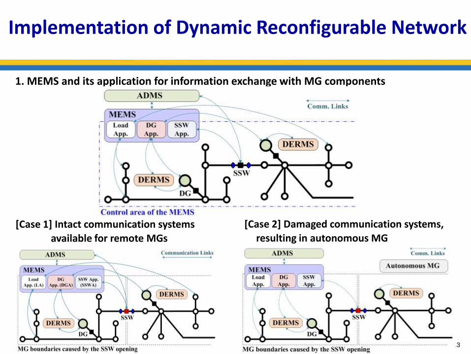
Implementation of Dynamic Reconfigurable Network
1. MEMS and its application for information exchange with MG components
[Case 1] Intact communication systems
available for remote MGs
[Case 2] Damaged communication systems,
resulting in autonomous MG

December 2008 14
Implementation of Dynamic Reconfigurable Network
2. MG frequency regulation of synchronous-machine DGs
[Case 1] Still under the control of MEMS with Intact communication systems
[Case 2] Operating as autonomous MG with a primary DG and following DGs

December 2008
Implementation of Dynamic Reconfigurable Network
1( )G
DGm DG G
d fP P D f
dt J
,DGm DGm DGv
t t
d P P P
dt T T
,
d
g GF g dDGv DGv GGF
v v g v v
P f Id P P ff
dt T T R T T
( ) ( ),d
GF GFf t f t
GF GF G
f f
d f f f
dt T T
( )( ) ( ) ( ) ,G L
dX tAX t A X t B P t
dt
( ) ,T
G DGm DGv GF GFX t f P P f f
( ) ( ) ( ) ( ) s
G LsX s AX s A e X s B P s
1
1
( ) ( ) ( )
1 / 2
1 / 2
s
G L G
G
f s P s CX s C sI A e A B
sC sI A A B
s
2. MG frequency regulation of synchronous-machine DGs
: Analysis of MG frequency stability for the parameter variations (e.g., droop constant, PI
controller gain, and communication time delay)
• A set of differential equations: • For the analysis of the root locus
where

December 2008 16
Implementation of Dynamic Reconfigurable Network
1
,
Δ Δ Δ
Δ Δ Δ
-
Pθ Qθ θP θQDG DG
P V QV V P V QDG DG
J J S Sθ P P= =
J J S SV Q Q
, , , ,,
, ,
k kmin max
DGk
V e V eQ
m k m k
Δ Δ Δ ΔDG DG DG DG
V Q V Q
S P Q S P Q
S S
, , , , .k DGn DGn
n n k
e m n P m n Q
Δ ΔDG DG V P V Q
S P Q S S
3. MG voltage regulation of synchronous-machine DGs
: The voltage regulation in a small-area MG can be sufficiently achieved via the output
voltage control of the DGs
: In the case of a wide-area MG, the coordination of DGs with voltage regulating devices
(e.g., shunt capacitors or static synchronous compensators) will be required to support
the feeder voltages such that the DG reactive power control can satisfy
where

December 2008 17
Implementation of Dynamic Reconfigurable Network
4. Automatic load restoration initiated by the MEMS with the following steps:
5. Time frame for the activation of the MEMS applications for fault isolation and load restoration
Step1
Calculating the extra capacities of the DGs that are located close to the de-energized
feeder
Step2 Selecting the MG that includes the DG with the largest extra capacity
Step3
Dividing the selected MG into the smallest networks if the MG accommodates at
least one SSW
Step4 Closing the SSW of the divided MG to restore the loads on the de-energized feeder
Step5
Reconnecting, if any, the DGs on the de-energized feeder to facilitate the load
restoration
Step6
Monitoring the MG frequency and voltage levels while preparing for other faults
and waiting for the resynchronization signal from the ADMS

December 2008
Implementation of Dynamic Reconfigurable Network 6. Changes in the boundaries of MGs and corresponding DG operation

December 2008 19
a. At Snapshot #2 (Steps 1 and 2) - Small tie-line power flow between interconnected MGs : In case where each unit MG has at least one DG in charge of secondary frequency regulation,
the tie-line power flow between interconnected MGs becomes small at the instant when the main
power-supply resource is disconnected.
b. At Snapshot #3 (Step 3) - Control of tie-line power flow between MGs 3 and 4 : For the intentional islanding of MGs 2 and 4, an additional feedback loop has been integrated into
the DG output control.
: MEMS 2 controls the power flow between two MGs to zero, in order to mitigate the impact of the
islanding on the DG operations.
6. Changes in the boundaries of MGs and corresponding DG operation (cont’d)
Implementation of Dynamic Reconfigurable Network

December 2008
Simulation Studies of Dynamic Reconfigurable Network
20
1. Before two faults occur at t = 8 sec and 25 sec, respectively,
: the DGs generating constant power and the main grid supplying variable power
Customer Class ZP IP PP ZQ IQ PQ
Residential A 1.50 -2.31 1.81 7.41 -11.97 5.55
Residential B 1.57 -2.48 1.91 9.28 -15.29 7.01
Residential C 1.56 -2.49 1.93 10.1 16.75 7.65
Commercial A 0.69 0.04 0.27 1.82 -2.24 1.43
Commercial B 0.77 -0.84 1.07 8.09 -13.65 6.56 0 0
0 0 0 0
, L L P P P L L Q Q Q
V V V VP P Z I P Q Q Z I P
V V V V
ZIP Load Parameters in the test bed [26]

December 2008 21
Simulation Studies of Dynamic Reconfigurable Network
2. Main parameters for the modeling of DG units
Parameters Explanations Values
Salient-Pole Synchronous
Machine
Srated Rated capacity 0.96 MVA
Vph-ph,rms Rated line-to-line voltage (RMS) 4.8 kV
J = 2H Moment of inertia 1.07 sec
P Pole pairs 2
Xd, Xd’, Xd’’, Xq, Xq’’, Xdl
Steady-State, transient, sub-transient, and leakage reactance
1.56, 0.296, 0.177,1.06, 0.177, 0.052 pu
Tq’, Tq’’, Tqo’’ Transient and sub-transient time constants
3.7, 0.05, 0.05 sec
Rs Stator resistance 0.0036 pu
P Control Rg Droop constant 3 ~ 5 %
Q Control
Tr LPF time constant 0.02 sec
Ka , Ta Regulator gain and time constant 200, 0.02 sec
Kf , Tf Damping filter gain and time constant 0.001, 0.1 sec
Vf,max Maximum field voltage 6 pu

December 2008 22
Simulation Studies of Dynamic Reconfigurable Network
3. Test Scenario for Case Studies
• (t < t1) The test grid operated under the normal condition; i.e., all the SSWs and DCBs
were closed and, for simplicity, all the DG power outputs PDG were maintained at 0.43 pu.
• (t = t1) A fault occurred on the distribution line between Nodes 29 and 30.
The SSWs1, 3, 5, 7 and DCB7 then opened, and the feedback controllers of the DGs were
activated for the real-time frequency and voltage regulation in the MGs.
• (t1 < t < t3) The MG including the DGs3, 4 (or, equivalently, the MG2 in the Snapshot #2)
was selected for the restoration, and divided into two networks by opening the SSW4
at t = t2.
• (t3 ≤ t < t4) The load service restoration was initiated by reclosing the SSW3 and the DCB7
at t = t3.

December 2008 23
Simulation Studies of Dynamic Reconfigurable Network
• (t = t4) Another fault occurred on the line between Nodes 9 and 12, resulting in the
opening of the SSW2 and DCB2.
• (t4 < t < t5) For the fault, the MG including the DG1 was the only one available for the
load restoration, and it was the smallest network (i.e., no SSWs within the MG).
• (t5 ≤ t) The DCB2 and SSW2 were closed to restore the de-energized loads. The MEMSs
of the islanded MGs waited for the resynchronization call while monitoring the power
flowing through the SSWs.
3. Test Scenario for Case Studies (Cont’d)

December 2008
Simulation Results: Dynamic Reconfigurable Network
24
1. Operations of Smart Switches (SSWs) and DG Circuit Breakers (DCBs)

December 2008 25
Simulation Results: Dynamic Reconfigurable Network
2. Variations in MG Frequency and DG Output Voltage at Points of Common Coupling (PCCs)

December 2008 26
3. Variations in Voltages across the Smart Switches and DG Circuit Breakers
at the Moments of Fault Occurrence and Load Restoration
Simulation Results: Dynamic Reconfigurable Network

December 2008
Future Work : Field Demonstration with Eaton
27
Eaton MV Test Feeder at Franksville, WI
• 24.9kV Utility source
• 3MVA Transformer at PCC
• 2.5MW Inverters with common DC bus and energy storage (enable circulating currents on feeder)
• 13.2kV feeder with various power apparatus, controls, and protection

December 2008
MV Test Feeder Capability and Benefit Highlights
28
• MV test feeder configuration operates at both grid-tied and islanded operation modes for power distribution DER interconnection and Microgrid applications;
• PV/ES Inverters support to create system operating scenarios with various PV penetration levels;
• PV/ES Inverters, line impedances, and Load banks located along the feeder serve as dynamic and static loads to create various power flow conditions within the network;
• Fault Injection Units are used to generate various fault scenarios within the network;
• Voltage regulators, Var compensators, and PV/ES inverters are used to support optimal volt/var control and voltage profile management
• Intelligent switching devices, e.g., reclosers, sectionalizers, and protective relays, are used to support optimal network reconfiguration via advanced control and protection technologies;
• The test feeder can also be used to demonstrate demand response and load control/management in coordination with system-level control;

December 2008 29

December 2008
Network Reconfiguration Use Case #1: Voltage Profile Management with High Penetration PV
30
OPEN
Section #1
Section #2
Configuration #1: Low PV Power

December 2008 31
Network Reconfiguration Use Case #1: Voltage Profile Management with High Penetration PV
OPEN
Section #1
Section #2
Configuration #2: High PV Power

December 2008
Network Reconfiguration Use Case #2: Fault Detection, Location and Restoration
32
OPEN
Section #1
Section #2
Fault
Configuration #1: Initial Pre-fault Configuration

December 2008 33
Network Reconfiguration Use Case #2: Fault Detection, Location and Restoration
OPEN
Section #1
Section #2
OPEN
Fault
Isolated Section
Critical load loses power
Configuration #2: Fault Isolation Configuration

December 2008 34
Network Reconfiguration Use Case #2: Fault Detection, Location and Restoration
Section #1
Section #2
OPEN
OPEN
Isolated Section
Critical load is recovered
CLOSE
Fault
Configuration #3: Critical Load Recovery Configuration

December 2008
References
[1] C. Chen, J. Wang, F. Qiu, D. Zhao, "Resilient Distribution System by Microgrids Formation After Natural Disasters", IEEE Trans. Smart Grid, vol. 7, no. 2, pp. 958-966, Mar. 2016.
[2] Laura Silva de Assis “Switch Allocation Problems in Power Distribution Systems” IEEE Trans. Power Syst., vol. 30, no. 1, pp. 246-253, Jan. 2015
[3] T. Creemers, L. R. Giralt, J. Riera, C. Ferrarons, J. Roca, X. Corbella, “Constraint-based Maintenance Scheduling on an Electric Power-Distribution Network”,
http://citeseerx.ist.psu.edu/viewdoc/download?doi=10.1.1.28.3561&rep=rep1&type=pdf
[4] Schneider Electric, Wastewater treatment plants: recommended electrical network design for efficient plant and energy operations http://www.schneider-
electric.com/solutions/id/en/med/25882144/application/pdf/1567_waterhandbook.pdf
[5] Welbeck Electricity Distribution, Choosing the right distribution network configuration http://welbeckelectricity.com/distribution-network-configuration/
[6] D.P. Bernardon, A.P. C. Mello, L. L. Pfitscher, L. N. Canha, A. R. Abaide, A. A. B. Ferreira, “Real-time reconfiguration of distribution network with distributed generation “, Electric Power
Systems Research, 107 (2014), pp. 59-67.
[7] E. López, H. Opazo, L. García, and P. Bastard, “Online Reconfiguration Considering Variability Demand: Applications to Real Networks” IEEE Trans. Power Syst., vol. 19, no. 1, Feb. 2004
[8] X. Fang, Z. Cai, Z. Guo, "Dynamic network reconfiguration using time-interval based strategy and improved moment method", Power Engineering Society General Meeting, 2005. IEEE, On
page(s): 271 – 277
[9] V. Farahani, B. Vahidi, and H. A. Abyaneh, “Reconfiguration and Capacitor Placement Simultaneously for Energy Loss Reduction Based on an Improved Reconfiguration Method,” IEEE
Trans. Power Syst., vol. 27, no. 2, pp. 587-595, May 2012.
[10] A.M. Tahboub, V.R. Pandi, H.H. Zeineldin, "Distribution System Reconfiguration for Annual Energy Loss Reduction Considering Variable Distributed Generation Profiles", IEEE Trans.
Power Del., vol. 30, no. 4, pp. 1677-1685, Aug. 2015
[11] Xiaodan Yu, Hongjie Jia, Chengshan Wang, Wei Wei, Yuan Zeng, and Jinli Zhao, "Network reconfiguration for distribution system with micro-grids," in Sustainable Power Generation and
Supply, 2009. SUPERGEN '09. International Conference on, 2009, pp. 1-4.
[12] Tan Sicong, Xu Jian-Xin, and S. K. Panda, "Optimization of Distribution Network Incorporating Distributed Generators: An Integrated Approach," Power Systems, IEEE Transactions on,
vol. 28, pp. 2421-2432, 2013.
[13] J. Li, X. Y. Ma, C. C. Liu, and K. P. Schneider, "Distribution System Restoration With Microgrids Using Spanning Tree Search," Power Systems, IEEE Transactions on, vol. PP, pp. 1-9,
2014.
[14] Pham Thi Thu Ha, Y. Besanger, and N. Hadjsaid, "New Challenges in Power System Restoration With Large Scale of Dispersed Generation Insertion," Power Systems, IEEE Transactions
on, vol. 24, pp. 398-406, 2009.
[15] Aboelsood Zidan and Ehab F. El-Saadany, "Incorporating load variation and variable wind generation in service restoration plans for distribution systems," Energy, vol. 57, pp. 682-691, 8/1/
2013.
[16] V. Kumar, H. C. R. Kumar, I. Gupta, and H. O. Gupta, "DG Integrated Approach for Service Restoration Under Cold Load Pickup," Power Delivery, IEEE Transactions on, vol. 25, pp. 398-
406, 2010.
[17] A. M. El-Zonkoly, "Power system single step restoration incorporating cold load pickup aided by distributed generation," International Journal of Electrical Power & Energy Systems, vol. 35,
pp. 186-193, 2// 2012
[18] J. Wang, X. Lu, C. Chen, “Guidelines for Implementing Advanced Distribution Management System – Requirements for DMS Integration with DERMS and Microgrids,” ANL Technical
Report, Aug. 2015.
[19] A. Bokhari et al., "Experimental determination of the ZIP coefficients for modern residential, commercial, and industrial loads", IEEE Trans. Power Del., vol. 29, no. 3, pp.1372-1381, June
2014
[20] P. Kunder, Power System Stability and Control, Toronto, CA: McGraw-Hill, 1994, pp. 581-626.
[21] L. Jiang, W. Yao, Q. H. Wu, J. Y. Wen, and S. J. Cheng, “Delay dependent stability for load frequency control with constant and time-varying delays,” IEEE Trans. Power Syst., vol. 27, no.
2, pp. 932–941, May 2012.
[22] X. Yu and K. Tomsovic, “Application of linear matrix inequalities for load frequency control with communication delay,” IEEE Trans. Power Syst., vol. 19, no. 3, pp. 1508–1515, Aug. 2004.

December 2008 36
Jianhui Wang ([email protected])
Thank you!
Youngjin Kim ([email protected]), Xiaonan Lu ([email protected]), Chen Chen ([email protected])

December 2008
Message Exchanges for Implementation of Dynamically Reconfigurable Network
37
Behaviors Messages received Messages sent Explanations
Islanded Range Determination
Performance –”REQUEST” Conversation ID –”OPEN/CLOSE” Content – ”magnitudes and directions of fault currents, node number of the switching nodes”
Performance –”ACCEPT/ DECLINE” Conversation ID –”OPEN/CLOSE” Receiver – “SSW Application (SSWA)”
1. Receives message from SSWA and accept or decline the opening/ closing requests(i.e., In case of a common physical link, decision is made to form a bigger island )
Coalition Performance –”REQUEST” Conversation ID – ”” Content – ”P & Q control modes, remaining load”
Performance –”ACCEPT/ DECLINE” Conversation ID – ”CONNECTED/ ISLANDED” Content – ”islanded range, synchronization conditions (Δf, |Δδ|, |ΔV|)” Receiver – “DG Application (DGA)”
1. The DGA is informed of the determined island ranges, the remaining load, and synchronization –ready conditions.
2. The DGA responds to the reference signals for frequency regulation.
3. Message of one DG agent is shared with other DG agents.
Information (message) exchange between MEMS applications
: i.e., DG application (DGA), SSW application (SSWA), and load application (LA) 1. MEMS

December 2008 38
Message Exchanges for Implementation of Dynamically Reconfigurable Network
Behaviors Messages received Messages sent Explanations
Grid Re-synchronizing
Performance –”REQUEST” Conversation ID –”RECONNECT” Content –” synchronization-ready conditions”
Performance –“REQUEST” Conversation ID –”RECONNECT” Content – ”node number of the connecting node, remaining load, island range, etc.” Receiver – “DG Application (DGA)/ SSW Application (SSWA)/Load Application (LA)”
1. Upon receiving the re-connection message from the DERMS, the MEMS request the DGA, SSWA and LA to connect islanded MG back to other MGs or the substation network.
Load Shedding/ Load Pickup
Performance –”REQUEST” Conversation ID– ”SHED/ RESTORE” Content – ”node number, remaining load, priority”
Performance – ” ACCEPT/ DECLINE” Conversation ID-”SHED/ RESTORE” Receiver – “Load Application (LA)”
1. Send from and receive messages from LA
1. MEMS (Cont’d)

December 2008 39
Message Exchanges for Implementation of Dynamically Reconfigurable Network
Behaviors Messages received Messages sent Explanations
Frequency/ Voltage Regulation
Performance –“REQUEST”
Conversation ID –”ISLANDED”
Content node number of generators, remaining load, priority”
Performance –“Increasing/Decreasing”
Conversation ID– ”node number of the connecting node, remaining load, etc.” Receiver – “SSW Application (SSWA)/Load Application (LA)”
1. Receive frequency and voltage regulation command from the MEMS or DERMS to operate the DGs in the specified operating range
3. Smart Switch Application
Behaviors Messages received Messages sent Explanations
Switching Action
Performance – “REQUEST” Conversation ID – ”SWITCHING” Content – “node number of the connecting/disconnecting node”
Performance – “ACCEPT/DECLINE” Conversation ID – ”SWITCHING” Content – “…” Receiver – “DG Application (DGA)”
1. Receive switching operation command from DGA, identifies the switch to be operated by the node number of the connecting node
2. DG Application

December 2008 40
Message Exchanges for Implementation of Dynamically Reconfigurable Network
Behaviors Messages received Messages sent Explanations
Power From Substation
Performance – “ACCEPT/DECLINE” Conversation ID – ”RESTORE” Content – “Source Power”
Performance – “REQUEST” Conversation ID – ”RESTORE” Content – “local name, load to restore”
1. Initiates the process of restoration, sends message to the MEMS and asks to supply power.
Power From DGs
Performance – “ACCEPT/DECLINE” Conversation ID – ”RESTORE” Content – “…”
Performance – “REQUEST” Conversation ID – ”RESTORE” Content – “local name, remaining load to restore, priority” Receiver – “DG Application”
1. Send message to the DG application and asks for remaining power to be restored
4. Load Application

December 2008
Conventional Service Restoration in Distribution Grids
41
Outage management system (OMS) will be initiated to assist the system operator with identifying the fault location, restoring service, coordinating crews, and generating reports.
SCADA
Automatic Metering System
Interactive Voice Response
Customer Info System
Other Applications in DMS
OMS
Remotely Control Commands
Dispatch Crews
Crews report
Perform Repair
and Restoration
However, the conventional OMS has the following limitations:
• Most distribution circuit faults are cleared by non-communicating fuses.
• System operators need additional information on
1. the status of distribution network, including the network damage and the number and locations of de-energized customers
2. the estimated restoration times that would be valuable to customers
(average restoration time in a distribution grid: 2.28 hours [2])
• Large possibility of human errors in the process of manual fault clearing

December 2008
Electric Utilities Installing Smart Switches
42
December 2008
Technology Development for Dynamic Reconfiguration of Distribution Network
43
2. Application of Advanced Distribution Management System (ADMS)
• Enabling the real-time reconfiguration of distribution networks, considering
1. Dynamic response characteristics of DGs that are equipped with centralized/decentralized frequency and voltage controllers;
2. Communication with PMUs or sensors (e.g., time delay, measurement errors);
3. Controllable demand response (DR) resources (e.g., batteries, HVAC systems).
3. Example: Schneider Electric’s Distribution Automation
• Improved the quality of service and network reliability
1. Reduction of the outage time (50%) and areas affected by network faults
2. Reduced costs for network investment, operation, and maintenance
• Easier implementation than usual SCADA projects
1. Scalability: 10 times faster than traditional SCADA
2. Monitoring system with high-speed data transfer between substations to clients

December 2008
Implementation of Dynamic Reconfigurable Network
44
1. Simple approach to identify fault location using the remote V/I sensors of the SSWs
: To address the practical difficulties in adopting the method of the Jacobian matrix
because of random load demand variation and unknown line impedance
: Once the load service restoration is completed, technicians can be dispatched to find
exact fault locations in the conventional way.
[Combination 1] The V/I sensors of adjacent SSW pairs looking in the same directions
[Combination 2] The V/I sensors of adjacent SSW pairs looking in the opposite directions
(i.e., forward/reverse)

December 2008
Implementation of Dynamic Reconfigurable Network
45
Directions of SSW Sensors
Fault Current Variations ΔIf = If (t = tf ‒ tΔ) ‒ If (t = tf)
Fault Locations
Left (+1)
Middle (0)
Right (‒1)
Same ΔIfl + ‒ ‒
ΔIfr + + ‒
#1 Opposite ΔIfl + + ‒
ΔIfr ‒ + +
#2 Opposite ΔIfl ‒ + +
ΔIfr + + ‒
Simple approach to identify fault location using the remote V/I sensors of the SSWs
: To address the practical difficulties in adopting the method of the Jacobian matrix
: For 9 possible combinations, regardless of the network topology,

December 2008 46
Implementation of Dynamic Reconfigurable Network
• Implementing a look-up table to determine where to open the SSWs at the moment of fault occurrence, such that the MGs can be formed with the smallest amount of de-energized load demand
SSWs SSW Opening Conditions: (SSW Pair) = fault location flag
SSW1 |flag| = 1 for any SSW pair
SSW2 1. (SSW2, SSW7) = 1
2. (SSW2, SSW7) = 0 & |flag| = 1 for any of the other SSW pairs
SSW3
1. (SSW3, SSW4) = 0 & |flag| = 1 for any of the other SSW pairs
2. (SSW3, SSW5) = 0, (SSW7, SSW3) = 0, (SSW7, SSW5) = 0 & |flag| = 1 for any of the
other SSW pairs
SSW4 1. (SSW3, SSW4) = ‒1
2. (SSW3, SSW4) = 0 & |flag| = 1 for any of the other SSW pairs
SSW5
1. (SSW5, SSW6) = 0 & |flag| = 1 for any of the other SSW pairs
2. (SSW3, SSW5) = 0, (SSW7, SSW3) = 0, (SSW7, SSW5) = 0 & |flag| = 1 for any of the
other SSW pairs
SSW6 1. (SSW5, SSW6) = ‒1
2. (SSW5, SSW6) = 0 & |flag| = 1 for any of the other SSW pairs
SSW7
1. (SSW2, SSW7) = 0 & |flag| = 1 for any of the other SSW pairs
2. (SSW3, SSW5) = 0, (SSW7, SSW3) = 0, (SSW7, SSW5) = 0 & |flag| = 1 for any of the
other SSW pairs

December 2008
Frequency Regulation using Inverter-Interfaced Batteries & Synchronous-Machine-Based DGs
Coordination control of batteries and DGs that compensate for the high- and low-frequency components of instantaneous power mismatch
(b) Only with DGs
(c) With DGs and Batteries : (top) PI and (bottom) PID Controllers for Batteries
(a) Power Spectrum Density of Dispatched Signals [27]

December 2008
Simulation Results: Frequency Regulation using Batteries
48
Coordinated control scheme of synchronous-machine-based DGs and batteries
(a) Only with DGs (b) With DGs and Batteries

December 2008 49
Simulation Results: Frequency Regulation using Batteries
Effects of the coordinated control on battery SOC variations, frequency deviations,
and DG output variations
(a)
SOC
var
iati
on
s
(b)
Fre
qu
en
cy d
evia
tio
ns
(c)
Ge
ne
rati
on
ram
p-r
ate
(d)
Max
imu
m o
utp
ut
vari
atio
ns