2012 International Residential Code - Fort Collins, Colorado · “R102.4 Referenced codes and...
61
ORDINANCE NO. 020, 2014 OF THE COUNCIL OF THE CITY OF FORT COLLINS AMENDING CHAPTER 5, ARTICLE II, DIVISION 2, OF THE CODE OF THE CITY OF FORT COLLINS FOR THE PURPOSE OF REPEALING THE 2009 INTERNATIONAL RESIDENTIAL CODE (IRC), AND ADOPTING THE 2012 INTERNATIONAL RESIDENTIAL CODE, WITH AMENDMENTS WHEREAS, since 1924, the City has reviewed, amended and adopted the latest nationally recognized building standards available for the times; and WHEREAS, upon recommendation of City staff, the City Council has determined that it is in the best interests of the City to align the five interconnected basic construction codes under one publication year; and WHEREAS, the five interconnected basic construction codes are the International Building Code, International Residential Code, International Mechanical Code, International Fuel Gas Code, and International Energy Conservation Code; and WHEREAS, the City Council has determined that the 2012 publication year of the five interconnected basic construction codes ought to be adopted and that their counterpart codes previously adopted should be repealed, both in order to align the publication years of the codes and also because the 2009 publications contain improvements in construction code regulation; and WHEREAS, City staff has conducted a significant public outreach program, working with the regulated construction industry and building professionals; and WHEREAS, the adoption of the five interconnected basic construction codes has been presented to and recommended by the Affordable Housing Board, the Commission on Disability, the Air Quality Advisory Board, the Natural Resources Advisory Board, the Building Review Board, the Electric Board, the Landmark Preservation Commission and the Water Board; and WHEREAS, the City Council has determined that it is in the best interest of the health, safety and welfare of the City and its citizens that the 2009 International Residential Code be repealed, and that in its place, the 2012 International Residential Code, be adopted, with amendments. NOW, THEREFORE, BE IT ORDAINED BY THE COUNCIL OF THE CITY OF FORT COLLINS as follows: Section 1. That Section 5-26(d) of the Code of the City of Fort Collins is hereby amended to read as follows: (d) Pursuant to the power and authority conferred on the City Council by Section 31- 16-202, C.R.S., and Article II, Section 7 of the Charter, the City Council hereby repeals - 1 -
Transcript of 2012 International Residential Code - Fort Collins, Colorado · “R102.4 Referenced codes and...
ORDINANCE NO. 020, 2014 OF THE COUNCIL OF THE CITY OF FORT COLLINS
AMENDING CHAPTER 5, ARTICLE II, DIVISION 2, OF THE CODE OF THE CITY OF FORT COLLINS FOR THE PURPOSE OF
REPEALING THE 2009 INTERNATIONAL RESIDENTIAL CODE (IRC), AND ADOPTING THE
2012 INTERNATIONAL RESIDENTIAL CODE, WITH AMENDMENTS
WHEREAS, since 1924, the City has reviewed, amended and adopted the latest nationally recognized building standards available for the times; and WHEREAS, upon recommendation of City staff, the City Council has determined that it is in the best interests of the City to align the five interconnected basic construction codes under one publication year; and WHEREAS, the five interconnected basic construction codes are the International Building Code, International Residential Code, International Mechanical Code, International Fuel Gas Code, and International Energy Conservation Code; and WHEREAS, the City Council has determined that the 2012 publication year of the five interconnected basic construction codes ought to be adopted and that their counterpart codes previously adopted should be repealed, both in order to align the publication years of the codes and also because the 2009 publications contain improvements in construction code regulation; and WHEREAS, City staff has conducted a significant public outreach program, working with the regulated construction industry and building professionals; and WHEREAS, the adoption of the five interconnected basic construction codes has been presented to and recommended by the Affordable Housing Board, the Commission on Disability, the Air Quality Advisory Board, the Natural Resources Advisory Board, the Building Review Board, the Electric Board, the Landmark Preservation Commission and the Water Board; and
WHEREAS, the City Council has determined that it is in the best interest of the health, safety and welfare of the City and its citizens that the 2009 International Residential Code be repealed, and that in its place, the 2012 International Residential Code, be adopted, with amendments. NOW, THEREFORE, BE IT ORDAINED BY THE COUNCIL OF THE CITY OF FORT COLLINS as follows: Section 1. That Section 5-26(d) of the Code of the City of Fort Collins is hereby amended to read as follows: (d) Pursuant to the power and authority conferred on the City Council by Section 31-
16-202, C.R.S., and Article II, Section 7 of the Charter, the City Council hereby repeals
- 1 -

the 20039 Edition of the International Residential Code, and adopts, as the residential building code of the City, the 200912 International Residential Code published by the International Code Council, as amended by the City, which shall have the same force and effect as though set forth in full herein. The subject matter of the International Residential Code adopted herein includes comprehensive provisions and standards for the protection of the public health and safety by prescribing regulations governing the construction, alteration, enlargement, relocation, replacement, repair, equipment, use and occupancy, location, removal and demolition of, and its applicability is hereby limited to, individual nonattached one- and two-family dwellings and multiple single-family dwellings (townhouses) not more than three (3) stories above grade in height with a separate means of egress, and their accessory structures.
Section 2. That Section 5-30 of the Code of the City of Fort Collins is hereby repealed and reenacted to read as follows: Sec. 5-30 Amendments and deletions to code. The 2012 INTERNATIONAL RESIDENTIAL CODE adopted herein is hereby amended in the following respects:
(1) Section R101.1 Title is hereby amended to read as follows:
“R101.1 Title. These provisions shall be known as the Residential Code for One- and Two-family Dwellings of the City of Fort Collins and shall be cited as such and will be referred to herein as “this code.”
(2) Section R102.4 Referenced codes and standards, is hereby amended to read as follows:
“R102.4 Referenced codes and standards. The codes and standards referenced in this code shall be those that are listed in Section 101.4 of the International Building Code, entitled ‘Referenced Codes’ and shall be considered part of the requirements of this code to the prescribed extent of each such reference. Where differences occur between provisions of this code and referenced codes and standards, the provisions of this code shall apply.”
(3) Section R103 Department of Building Safety is hereby amended in its entirety to read as
follows:
SECTION R103 DEPARTMENT OF BUILDING SAFETY R103.1 Creation of enforcement agency. The Department of Building Safety is hereby created and the official in charge thereof shall be known as the building official. R103.2 Appointment. The building official shall be appointed by the chief appointing authority of the jurisdiction.
- 2 -

R103.3 Deputies. In accordance with the prescribed procedures of this jurisdiction and with the concurrence of the appointing authority, the building official shall have the authority to appoint a deputy building official, the related technical officers, inspectors, plan examiners and other employees. Such employees shall have powers as delegated by the building official. For the maintenance of existing properties, see the International Property Maintenance Code.
“R103 Code Administration. R103.1 Entity charged with code administration shall be as determined in accordance with Section 103 of the International Building Code, entitled ‘Code Administration’.”
(4) Section R105.2 Work exempt from permit, items 1, 2, 3, 5, 7, 8, 9, 11, 12, 13, 14 under the heading of “Building” are amended or added to read as follows:
“Building: 1.”One-story detached accessory structures used as tool and storage sheds, playhouses and similar uses, for lawn and garden equipment storage, tool storage and similar uses, including arbors, pergolas, and similar structures, provided the floor area does not exceed 200 square feet (18.58 m2). 120 square feet (11.15 m2) or 8 feet (2.438 m) in height, and the structures do not house flammable liquids in quantities exceeding 10 gallons (38 l) per building and are constructed entirely of noncombustible materials when located less than 3 feet (0.914 m) from an adjoining property line. 2. Fences not over 7 feet (2134 mm) 6 feet (1829 mm) high. 3. Retaining walls that are not over 4 feet (1219 mm) in height measured from the bottom of the footing low side grade to the top of the wall, provided the horizontal distance to the next uphill retaining wall is at least equal to the total height of the lower retaining wall, unless supporting a surcharge or impounding Class I, II or IIIA liquids. 4. Water tanks supported directly upon grade if the capacity does not exceed 5,000 gallons (18,927 L) and the ratio of height to diameter or width does not exceed 2 to 1. 5. Platforms intended for human occupancy or walking, sidewalks and driveways if such structures are not more than 30 inches (762 mm) above adjacent grade, and are not over any basement window or story below, and are not part of an accessible route. 6. Painting, papering, tiling, carpeting, cabinets, counter tops and similar finish work. 7. Prefabricated and portable swimming pools that are less than 24 inches (610 mm) deep. or wading pools, hot tubs or spas if such structures are supported directly upon grade when the walls of such structures are entirely above grade, and if such structures cannot contain water more than 24 inches (610 mm) deep.
- 3 -

8. Swings and other playground equipment, including one elevated playhouse per lot designed and used exclusively for play, not exceeding 64 square feet (5.9 m2) of floor area or 6 feet (1.82 m) in height as measured from the floor to the highest point of such structure. 9. Window awnings supported by an exterior wall which do not project more than 54 inches (1372 mm) from the exterior wall and do not require additional support. Window replacement requiring no structural alteration. Window replacement requiring no change in the window configuration which reduces the size of the window opening. Window replacement when such work is determined not to be historically significant. Storm window, storm door and rain gutter installation. 10. Decks not exceeding 200 square feet (18.58 m2) in area, that are not more than 30 inches (762 mm) above grade at any point, are not attached to a dwelling, and do not serve the exit door required by Section R311.4. 11. Roofing repair or replacement work not exceeding one square (100 square feet) of covering per building. 12. Replacement of nonstructural siding when the removal of siding is performed in accordance with State laws regarding asbestos and lead paint.
13. Minor work valued at less than $500 when such minor work does not involve alteration of structural components, fire-rated assemblies, plumbing, electrical, mechanical or fire-extinguishing systems.
14. Decorative ponds, fountains and pools no more than 24 inches (610 mm) deep.”
(5) Section R105.2 Work exempt from permit, is further amended by deleting all headings and
references under Electrical, Gas, and Mechanical. Electrical: 1. Listed cord-and-plug connected temporary decorative lighting. 2. Reinstallation of attachment plug receptacles but not the outlets there for. 3. Replacement of branch circuit over-current devices of the required capacity in the same location. 4. Electrical wiring, devices, appliances, apparatus or equipment operating at less than 25 volts and not capable of supplying more than 50 watts of energy. 5. Minor repair work, including the replacement of lamps or the connection of approved portable electrical equipment to approved permanently installed receptacles. Gas: 1. Portable heating, cooking or clothes drying appliances. 2. Replacement of any minor part that does not alter approval of equipment or make such equipment unsafe.
- 4 -

3. Portable-fuel-cell appliances that are not connected to a fixed piping system and are not interconnected to a power grid. Mechanical: 1. Portable heating appliances. 2. Portable ventilation appliances. 3. Portable cooling units. 4. Steam, hot- or chilled-water piping within any heating or cooling equipment regulated by this code. 5. Replacement of any minor part that does not alter approval of equipment or make such equipment unsafe. 6. Portable evaporative coolers. 7. Self-contained refrigeration systems containing 10 pounds (4.54 kg) or less of refrigerant or that are actuated by motors of 1 horsepower (746 W) or less. 8. Portable-fuel-cell appliances that are not connected to a fixed piping system and are not interconnected to a power grid.
The stopping of leaks in drains, water, soil, waste or vent pipe; provided, however, that if any concealed trap, drainpipe, water, soil, waste or vent pipe becomes defective and it becomes necessary to remove and replace the same with new material, such work shall be considered as new work and a permit shall be obtained and inspection made as provided in this code. The clearing of stoppages or the repairing of leaks in pipes, valves or fixtures, and the removal and reinstallation of water closets, provided such repairs do not involve or require the replacement or rearrangement of valves, pipes or fixtures.
(6) Section R105.5 Expiration is hereby amended by adding a second paragraph to read as
follows:
“Both prior to and subsequent to the effective date of this code, any work authorized by a permit regulated by this code or any other building construction code administered by the building official that involves the construction or alteration of an exterior building component, assembly or finish material, such as the foundation, wall and roof framing, sheathing, siding, fenestration, and roof covering, shall be fully finished for permanent outdoor exposure within 24 months of the date of issuance of such permit, regardless of when the permit was issued.”
(7) Section R105.10 Premises Identification is hereby added to read as follows:
“R105.10 Premises Identification During Construction. The approved permit number and street address number shall be displayed and be plainly visible and legible from the public street or road fronting the property on which any new building is being constructed.”
(8) Section R105.11 Transfer of permits, is hereby added to read as follows:
- 5 -

“R105.11 Transfer of permits. A current valid building permit may be transferred from one party to another upon written application to the building official. When any substantial changes are made to the original plans and specifications submitted with the permit, as determined by the building official, a new plan review fee shall be paid as calculated in accordance with Section R108. A fee of $50 shall be paid to cover administrative costs for all building permit transfers. No change shall be made in the expiration date of the original permit.”
(9) Section R106.1.3 Information for construction in flood hazard areas is hereby amended to
read as follows:
R106.1.3 Information for construction in flood hazard areas. For buildings and structures located in whole or in part in flood hazard areas as established by Table R301.2(1), construction documents shall include: 1. Delineation of flood hazard areas, floodway boundaries and flood zones and the design flood elevation, as appropriate; 2. The elevation of the proposed lowest floor, including basement; in areas of shallow flooding (AO Zones), the height of the proposed lowest floor, including basement, above the highest adjacent grade; 3. The elevation of the bottom of the lowest horizontal structural member in coastal high hazard areas (V Zone); and 4. If design flood elevations are not included on the community’s Flood Insurance Rate Map (FIRM), the building official and the applicant shall obtain and reasonably utilize any design flood elevation and floodway data available from other sources.
“R106.1.3 Information for construction in flood hazard areas “For buildings or structures regulated under the scope of this code that are in whole or in part located in flood hazard areas, construction documents shall be submitted as established in accordance with Chapter 10 of the City Code, entitled ‘Flood Prevention and Protection’.”
(10) Section R106.1.4 Grading performance plans and certificate, is hereby added to read as
follows:
“R106.1.4 Grading performance plans and certificate. Every building permit application for a new building regulated by this code shall be accompanied by a site drainage/grading performance plan as prescribed by City standards. Drainage plans shall be submitted to and approved by the City’s Storm Drainage department prior to the issuance of the permit.”
(11) Section R106.3.1 Approval of construction documents, is hereby amended to read as
follows:
“R106.3.1 Approval of construction documents. When the building official issues a permit, the construction documents shall be approved in writing or by a stamp. Which
- 6 -

states “REVIEWED FOR CODE COMPLIANCE.” One set of construction documents so reviewed shall be retained by the building official. The other set shall be returned to the applicant, shall be kept at the site of work and shall be open to inspection by the building official or his or her authorized representative.”
(12) Section R107, Temporary Structures and Uses, is deleted in its entirety.
SECTION R107 TEMPORARY STRUCTURES AND USES R107.1 General. The building official is authorized to issue a permit for temporary structures and temporary uses. Such permits shall be limited as to time of service, but shall not be permitted for more than 180 days. The building official is authorized to grant extensions for demonstrated cause. R107.2 Conformance. Temporary structures and uses shall conform to the structural strength, fire safety, means of egress, light, ventilation and sanitary requirements of this code as necessary to ensure the public health, safety and general welfare. R107.3 Temporary power. The building official is authorized to give permission to temporarily supply and use power in part of an electric installation before such installation has been fully completed and the final certificate of completion has been issued. The part covered by the temporary certificate shall comply with the requirements specified for temporary lighting, heat or power in NFPA 70.
R107.4 Termination of approval. The building official is authorized to terminate such permit for a temporary structure or use and to order the temporary structure or use to be discontinued.
(13) Section R108, FEES, is hereby amended in its entirety to read as follows:
SECTION R108 FEES R108.1 Payment of fees. A permit shall not be valid until the fees prescribed by law have been paid. Nor shall an amendment to a permit be released until the additional fee, if any, has been paid. R108.2 Schedule of permit fees. On buildings, structures, electrical, gas, mechanical and plumbing systems or alterations requiring a permit, a fee for each permit shall be paid as required, in accordance with the schedule as established by the applicable governing authority. R108.3 Building permit valuations. Building permit valuation shall include total value of the work for which a permit is being issued, such as electrical, gas, mechanical, plumbing equipment and other permanent systems, including materials and labor. R108.4 Related fees. The payment of the fee for the construction, alteration, removal or demolition for work done in connection with or concurrently with the work authorized by a building permit shall not relieve the applicant or holder of the permit from the payment of other fees that are prescribed by law.
- 7 -
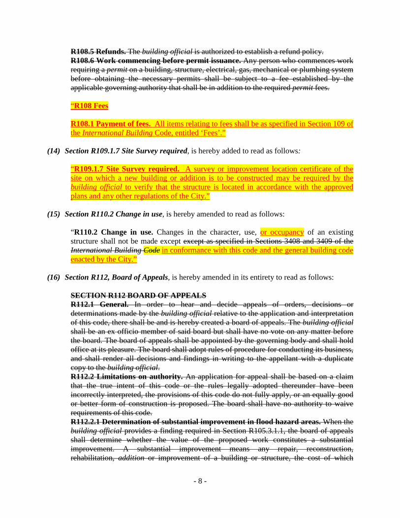
R108.5 Refunds. The building official is authorized to establish a refund policy. R108.6 Work commencing before permit issuance. Any person who commences work requiring a permit on a building, structure, electrical, gas, mechanical or plumbing system before obtaining the necessary permits shall be subject to a fee established by the applicable governing authority that shall be in addition to the required permit fees.
“R108 Fees R108.1 Payment of fees. All items relating to fees shall be as specified in Section 109 of the International Building Code, entitled ‘Fees’.”
(14) Section R109.1.7 Site Survey required, is hereby added to read as follows:
“R109.1.7 Site Survey required. A survey or improvement location certificate of the site on which a new building or addition is to be constructed may be required by the building official to verify that the structure is located in accordance with the approved plans and any other regulations of the City.”
(15) Section R110.2 Change in use, is hereby amended to read as follows:
“R110.2 Change in use. Changes in the character, use, or occupancy of an existing structure shall not be made except except as specified in Sections 3408 and 3409 of the International Building Code in conformance with this code and the general building code enacted by the City.”
(16) Section R112, Board of Appeals, is hereby amended in its entirety to read as follows:
SECTION R112 BOARD OF APPEALS R112.1 General. In order to hear and decide appeals of orders, decisions or determinations made by the building official relative to the application and interpretation of this code, there shall be and is hereby created a board of appeals. The building official shall be an ex officio member of said board but shall have no vote on any matter before the board. The board of appeals shall be appointed by the governing body and shall hold office at its pleasure. The board shall adopt rules of procedure for conducting its business, and shall render all decisions and findings in writing to the appellant with a duplicate copy to the building official. R112.2 Limitations on authority. An application for appeal shall be based on a claim that the true intent of this code or the rules legally adopted thereunder have been incorrectly interpreted, the provisions of this code do not fully apply, or an equally good or better form of construction is proposed. The board shall have no authority to waive requirements of this code. R112.2.1 Determination of substantial improvement in flood hazard areas. When the building official provides a finding required in Section R105.3.1.1, the board of appeals shall determine whether the value of the proposed work constitutes a substantial improvement. A substantial improvement means any repair, reconstruction, rehabilitation, addition or improvement of a building or structure, the cost of which
- 8 -
equals or exceeds 50 percent of the market value of the building or structure before the improvement or repair is started. If the building or structure has sustained substantial damage, all repairs are considered substantial improvement regardless of the actual repair work performed. The term does not include: 1. Improvements of a building or structure required to correct existing health, sanitary or safety code violations identified by the building official and which are the minimum necessary to assure safe living conditions; or 2. Any alteration of an historic building or structure, provided that the alteration will not preclude the continued designation as an historic building or structure. For the purpose of this exclusion, an historic building is: 2.1. Listed or preliminarily determined to be eligible for listing in the National Register of Historic Places; or 2.2. Determined by the Secretary of the U.S. Department of Interior as contributing to the historical significance of a registered historic district or a district preliminarily determined to qualify as an historic district; or 2.3. Designated as historic under a state or local historic preservation program that is approved by the Department of Interior. R112.2.2 Criteria for issuance of a variance for flood hazard areas. A variance shall be issued only upon: 1. A showing of good and sufficient cause that the unique characteristics of the size, configuration or topography of the site render the elevation standards in Section R322 inappropriate. 2. A determination that failure to grant the variance would result in exceptional hardship by rendering the lot undevelopable. 3. A determination that the granting of a variance will not result in increased flood heights, additional threats to public safety, extraordinary public expense, cause fraud on or victimization of the public, or conflict with existing local laws or ordinances. 4. A determination that the variance is the minimum necessary to afford relief, considering the flood hazard. 5. Submission to the applicant of written notice specifying the difference between the design flood elevation and the elevation to which the building is to be built, stating that the cost of flood insurance will be commensurate with the increased risk resulting from the reduced floor elevation, and stating that construction below the design flood elevation increases risks to life and property. R112.3 Qualifications. The board of appeals shall consist of members who are qualified by experience and training to pass on matters pertaining to building construction and are not employees of the jurisdiction. R112.4 Administration. The building official shall take immediate action in accordance with the decision of the board.
- 9 -

“R112 Board of Appeals R112.1 General. Appeals of decisions, determinations and interpretations of this code shall be made pursuant to the applicable provisions set forth in Section 113 of the adopted International Building Code, entitled ‘Board of Appeals’.”
(17) Section R113.4 Violation penalties, is hereby amended to read as follows:
“R113.4 Violation penalties. Any person who violates a provision of this code or fails to comply with any of the requirements thereof or who erects, constructs, alters or repairs a building or structure in violation of the approved construction documents or directive of the building official, or of a permit or certificate issued under the provisions of this code, shall be subject to penalties as prescribed by law. shall be guilty of a misdemeanor and shall be subject to the penalties and fines specified in Section 1-15 of the City Code.”
(18) Section R113.5 Work commencing before permit issuance is hereby added to read as
follows:
“R113.5 Work commencing before permit issuance. In addition to the penalties set forth in R113.4, any person or firm who, before obtaining the necessary permit(s), commences any construction of, or work on, a building, structure, electrical, gas, mechanical or plumbing system that is not otherwise exempted from obtaining a permit, shall be subject to a fine in addition to the standard prescribed permit fee. Said fine shall be equal in amount to the permit fee, except that it shall not be less than $50 nor more than $1,000 for the first such violation. A person or firm committing the same such violation repeatedly shall be subject to a fine equal to double the amount of the permit fee or double the amount of the fee imposed for the preceding violation, whichever is greater, for every such subsequent violation committed within 180 days of a previous violation. Said fines may be appealed to the City Manager pursuant to Chapter 2, Article VI of the City Code.”
(19) Section R202, Definitions, terms are hereby amended or added in alphabetical sequence in
the following respects:
The term, “BASEMENT”, is hereby amended to read as follows:
“BASEMENT. A story that is not a story above grade plane. (see “Story above grade plane”). That portion of a building located partly or completely below grade, wherein the underside of the floor area above the basement floor is 72 inches (1829 mm) or more above the surface of an approved permanent basement floor.” The term, “CITY” is hereby added to read as follows:
- 10 -

“The word CITY shall mean the municipal corporation of Fort Collins, Colorado, including its physical location and boundaries.” The term, “CRAWL SPACE” is hereby added to read as follows: “CRAWL SPACE. That portion of a building that is conditioned or non-conditioned space located partly or completely below grade (excluding the under-floor space beneath below-grade structural floor systems), wherein the underside of the adjacent finished floor above is less than 72 inches (1829 mm) above the bottom surface of such crawl space.” The term, “DWELLING” is hereby amended to read as follows: DWELLING. Any building that contains one or two dwelling units used, intended, or designed to be built, used, rented, leased, let or hired out to be occupied, or that are occupied for living purposes. A building used exclusively for residential occupancy and for permitted accessory uses, including single-family dwellings, two-family dwellings and multi-family dwellings, and which contains: (a) a minimum of 800 square feet of floor area, or (b) in the case of a dwelling to be constructed on the rear portion of a lot in the L-M-N, M-M-N, N-C-L, N-C-M, N-C-B, C-C-N, C-C-R, H-C or E zone districts, a minimum of 400 square feet of floor area, so long as a dwelling already exists on the front portion of such lot. The term dwelling shall not include hotels, motels, tents or other structures designed or used primarily for temporary occupancy. Any dwelling shall be deemed to be a principal building.”
The term, “DWELLING UNIT” is hereby amended to read as follows:
DWELLING UNIT. A single unit providing complete independent living facilities for one or more persons, including permanent provisions for living, sleeping, eating, cooking and sanitation. One or more rooms and a single kitchen and at least one bathroom, designed, occupied or intended for occupancy as separate quarters for the exclusive use of a single family for living, cooking and sanitary purposes, located in a single-family, two-family or multi-family dwelling or mixed-use building.” The term, “FAMILY” is hereby added to read as follows: “FAMILY. Any number of persons who are all related by blood, marriage, adoption, guardianship or other duly authorized custodial relationship, and who live together as a single housekeeping unit and share common living, sleeping, cooking and eating facilities.” The term, “FLOOR AREA” is hereby added to read as follows: “FLOOR AREA. The area included within the surrounding exterior walls of a building or portion thereof, exclusive of vent shafts and courts. The floor area of a building, or portion thereof, not provided with surrounding exterior walls shall be the usable area under the horizontal projection of the roof or floor above.”
- 11 -

The term, “GRADE” is hereby amended to read as follows: “GRADE The finished ground level adjoining the building at all exterior walls. (ADJACENT GROUND ELEVATION). The lowest point of elevation of the finished surface of the ground, paving or sidewalk between the building and the property line or, when the property line is more than 5 feet (1.524 m) from the building, between the building and a line 5 feet (1.524 m) from the building.” The term “ROOM, SLEEPING (BEDROOM”), is hereby added to read as follows: “ROOM, SLEEPING (BEDROOM). A habitable space within a dwelling or other housing unit designed primarily for the purpose of sleeping. The presence of a bed, cot, mattress, convertible sofa or other similar furnishing used for sleeping purposes shall be prima facie evidence that such space or room is a sleeping room. The presence of closets and similar storage facilities shall not be considered a relevant factor in determining whether or not a room is a sleeping room.”
The term “SITE”, is hereby added to read as follows: “SITE. A parcel of land bounded by a property line or a designated portion of a public right-of-way.” The term, “TOWNHOUSE”, is hereby amended to read as follows: “TOWNHOUSE: A single-family dwelling unit constructed in a group of three two or more attached individual units in which each unit extends from foundation to roof and with a yard or public way on at least two sides., each of which is separated from the other from the foundation to the roof and is located entirely on a separately recorded and platted parcel of land (site) bounded by property lines that is deeded exclusively for such single-family dwelling.”
(20) Section 301.1.3 Engineered Design is hereby amended to read as follows:
“R301.1.3 Engineered design. When a building of otherwise conventional light-frame construction contains structural elements exceeding the limits of Section R301 or otherwise not conforming to this code, these elements shall be designed in accordance with accepted engineering practice. The extent of such design need only demonstrate compliance of nonconventional elements with other applicable provisions and shall be compatible with the performance of the conventional framed system. Engineered design, in accordance with the Building Code enacted by the City, is permitted for all buildings, structures, and portions thereof included in the scope of this code.”
(21) Table R301.2(1), Climatic and Geographic Design criteria, is hereby amended to read as
follows:
- 12 -

For SI: 1 pound per square foot = 0.0479 kPa, 1 mile per hour = 0.447 m/s. a. Weathering may require a higher strength concrete or grade of masonry than necessary to satisfy the structural requirements of this code. The weathering column shall be filled in with the weathering index (i.e., “negligible,” “moderate” or “severe”) for concrete as determined from the Weathering Probability Map [Figure R301.2(3)]. The grade of masonry units shall be determined from ASTM C 34, C 55, C 62, C 73, C 90, C 129, C 145, C 216 or C 652. b. The frost line depth may require deeper footings than indicated in Figure R403.1(1). The jurisdiction shall fill in the frost line depth column with the minimum depth of footing below finish grade. c. The jurisdiction shall fill in this part of the table to indicate the need for protection depending on whether there has been a history of local subterranean termite damage. d. The jurisdiction shall fill in this part of the table with the wind speed from the basic wind speed map [Figure R301.2(4)A]. Wind exposure category shall be determined on a site-specific basis in accordance with Section R301.2.1.4. e. The outdoor design dry-bulb temperature shall be selected from the columns of 971/2-percent values for winter from Appendix D of the International Plumbing Code. Deviations from the Appendix D temperatures shall be permitted to reflect local climates or local weather experience as determined by the building official. f. The jurisdiction shall fill in this part of the table with the seismic design category determined from Section R301.2.2.1. g. The jurisdiction shall fill in this part of the table with (a) the date of the jurisdiction’s entry into the National Flood Insurance Program (date of adoption of the first code or ordinance for management of flood hazard areas), (b) the date(s) of the Flood Insurance Study and (c) the panel numbers and dates of all currently effective FIRMs and FBFMs or other flood hazard map adopted by the authority having jurisdiction, as amended. h. In accordance with Sections R905.2.7.1, R905.4.3.1, R905.5.3.1, R905.6.3.1, R905.7.3.1 and R905.8.3.1, where there has been a history of local damage from the effects of ice damming, the jurisdiction shall fill in this part of the table with “YES.” Otherwise, the jurisdiction shall fill in this part of the table with “NO.” i. The jurisdiction shall fill in this part of the table with the 100-year return period air freezing index (BF-days) from Figure R403.3(2) or from the 100-year (99 percent) value on the National Climatic Data Center data table “Air Freezing Index-USA Method (Base 32°F)” at www.ncdc.noaa.gov/fpsf.html. j. The jurisdiction shall fill in this part of the table with the mean annual temperature from the National Climatic Data Center data table “Air Freezing Index- USA Method (Base 32°F)” at www.ncdc.noaa.gov/fpsf.html. k. In accordance with Section R301.2.1.5, where there is local historical data documenting structural damage to buildings due to topographic wind speed-up effects,
GROUNDSNOW LOAD
WIND SPEED b
SEISMIC DESIGN CATE-GORY
SUBJECT TO DAMAGE FROM WINTER DESIGN TEMP
AIR FREEZ-ING INDEXe
MEAN ANN-UAL TEMP.f
FLOODd HAZARDS
Weatheringa
Roof Ice Damming
Frost line depth
Termite
Decayc
30psf
(1436.4pa)
100mph (161 kph)
B
Severe
No
30 inches (762mm)
Slight to Moderate
None to Slight
+6o F (-14o C)
906
48.4
July 16, 1979
- 13 -

the jurisdiction shall fill in this part of the table with “YES.” Otherwise, the jurisdiction shall indicate “NO” in this part of the table. For SI: °C = [(°F)-32]/1.8.
a. “Weathering may require a higher strength concrete or grade of masonry than necessary to satisfy the standard structural requirements of this code. The weathering column is based on the weathering index (i.e. “severe”) for concrete as determined from the Weathering Probability Map [Figure R301.2 (3)]. The grade of masonry units shall be determined from ASTM C 34, C 55, C 62, C 73, C 90, C 129, C 145, C 216 or C 652.
b. Wind exposure category shall be determined on a site-specific basis in accordance with Section R301.2.1.4.
c. Decay is determined in accordance with Figure R301.2(7).
d. July 16, 1979 is the date of the City’s entry into the National Flood Insurance Program (date of adoption of the first code or ordinance for management of flood hazard areas).
e. The 100-year return period air freezing index (BF-days) is established from Figure R403.3(2) or from the 100-year (99 percent) value on the National Climatic Data Center data table Air Freezing Index- USA Method (Base 32o Fahrenheit) at www.ncdc.noaa.gov/fpsf.html.
f. The mean annual temperature is established from the National Climatic Data Center data table “Air Freezing Index-USA Method (Base 32o Fahrenheit) at www.ncdc.noaa.gov/fpsf.html.”
(22) Section R301.2.1.5.2 Basic Wind Speed is hereby added, to read as follows:
“R301.2.1.5.2 Basic Wind Speed. The Special Wind Region as indicated on Figure R301.2(4) of this code shall apply using a Basic Wind Speed of 100 miles per hour (161 kph) based on the exposure category as described in Section R301.2.1.4, or the equivalent pressure thereto.”
(23) Section R302.1 Exterior walls, is hereby amended to read as follows:
“R302.1 Exterior walls. Construction, projections, openings and penetrations of exterior walls of dwellings and accessory buildings shall comply with Table R302.1 as amended (1); or dwellings equipped throughout with an automatic sprinkler system installed in accordance with Section P2904 shall comply with Table R302.1(2).”
(24) Section R302.1.1 Exterior wall finish materials, is hereby added to read as follows:
“R302.1.1 Exterior wall finish materials Walls of dwellings located within the fire separation distance (location from property line) of 0 feet to less than 5 feet shall be constructed of exterior finishes containing cementitious materials.
- 14 -
Exception: Dwellings equipped throughout with an automatic sprinkler system installed in accordance with Section P2904 or NFPA 13D.”
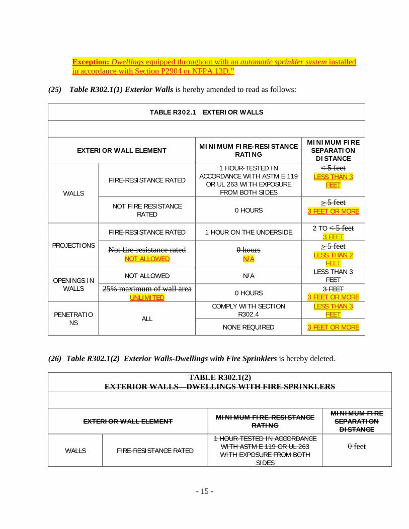
(25) Table R302.1(1) Exterior Walls is hereby amended to read as follows:
TABLE R302.1 EXTERIOR WALLS
EXTERIOR WALL ELEMENT MINIMUM FIRE-RESISTANCE RATING
MINIMUM FIRE SEPARATION
DISTANCE
WALLS
FIRE-RESISTANCE RATED
1 HOUR-TESTED IN ACCORDANCE WITH ASTM E 119
OR UL 263 WITH EXPOSURE FROM BOTH SIDES
< 5 feet LESS THAN 3
FEET
NOT FIRE RESISTANCE RATED 0 HOURS
> 5 feet 3 FEET OR MORE
PROJECTIONS
FIRE-RESISTANCE RATED 1 HOUR ON THE UNDERSIDE 2 TO < 5 feet 3 FEET
Not fire-resistance rated NOT ALLOWED
0 hours N/A
> 5 feet LESS THAN 2
FEET
OPENINGS IN WALLS
NOT ALLOWED N/A LESS THAN 3 FEET
25% maximum of wall area UNLIMITED
0 HOURS 3 FEET 3 FEET OR MORE
PENETRATIONS ALL
COMPLY WITH SECTION R302.4
LESS THAN 3 FEET
NONE REQUIRED 3 FEET OR MORE
(26) Table R302.1(2) Exterior Walls-Dwellings with Fire Sprinklers is hereby deleted.
TABLE R302.1(2) EXTERIOR WALLS—DWELLINGS WITH FIRE SPRINKLERS
EXTERIOR WALL ELEMENT MINIMUM FIRE-RESISTANCE RATING
MINIMUM FIRE SEPARATION
DISTANCE
WALLS FIRE-RESISTANCE RATED
1 HOUR-TESTED IN ACCORDANCE WITH ASTM E 119 OR UL 263 WITH EXPOSURE FROM BOTH
SIDES
0 feet
- 15 -

NOT FIRE RESISTANCE RATED 0 HOURS 3 feet
PROJECTIONS
FIRE-RESISTANCE RATED 1 HOUR ON THE UNDERSIDE 2 feet
Not fire-resistance rated
0 hours 3 feet
OPENINGS IN WALLS
NOT ALLOWED N/A LESS THAN 3 FEET
UNLIMITED 0 HOURS 3 FEET
PENETRATIONS ALL
COMPLY WITH SECTION R302.4 LESS THAN 3 FEET
NONE REQUIRED 3 FEET OR MORE
(27) Section R302.2 Townhouses, is hereby amended to read as follows:
“R302.2 Townhouses. Each townhouse shall be considered a separate building and shall be separated by a two-hour fire-resistance rated wall assemblies meeting the requirements of Section R302.1 for exterior walls. Effective August 1, 2014, townhouses shall be provided with a fire-suppression system as per P2904. Exception: Effective August 1, 2014, a common one-hour fire-resistance-rated wall assembly tested in accordance with ASTME 119 or UL 263 is permitted for townhouses if such walls do not contain plumbing or mechanical equipment, ducts or vents in the cavity of the common wall. The wall shall be rated for fire exposure from both sides and shall extend to and be tight against exterior walls and the underside of the roof sheathing. Electrical installations shall be installed in accordance with Chapters 34 through 43. Penetrations of electrical outlet boxes shall be in accordance with Section R302.4.”
(28) Section R302.2.1 Continuity is hereby amended to read as follows:
“R302.2.1 Continuity. The fire-resistance-rated adjoining wall or assembly separating townhouses along property lines shall be continuous from the foundation to the underside of the roof sheathing, deck or slab. The fire-resistance rating shall extend the full length of the wall or assembly, including wall extensions through and separating attached enclosed accessory structures. The fire-resistance-rated adjoining wall shall extend to the outer edge of horizontal projecting elements such as balconies, roof overhangs, canopies, marquees and similar projections”
(29) Section R302.3 Two-family dwellings is hereby amended to read as follows:
“R302.3 Two-family dwellings. Dwelling units in two-family dwellings shall be separated from each other by wall and/or floor assemblies having not less than a one-hour two-hour fire-resistance rating or by two walls, each of one-hour fire-resistance rating when tested in accordance with ASTME 119 or UL 263. Fire-resistance-rated floor-
- 16 -

ceiling and wall assemblies shall extend to and be tight against the exterior wall, and wall assemblies shall extend from the foundation to the underside of the roof sheathing. Effective August 1, 2014, two-family dwellings shall be provided with a fire-suppression system as per P2904.
Exceptions: 1. A fire-resistance rating of ½one-half hour shall be permitted in buildings equipped throughout with an automatic sprinkler system installed in accordance with NFPA 13. 2. Wall assemblies in buildings equipped with a fire suppressions system complying with NFPA 13, 13R or IRC P2904, need not extend through attic spaces when the ceiling is protected by not less than 5/8-inch (15.9 mm) Type X gypsum board and an attic draft stop constructed as specified in Section R302.12.1 is provided above and along the wall assembly separating the dwellings. The structural framing supporting the ceiling shall also be protected by not less than 1/2-inch (12.7 mm) gypsum board or equivalent. 3. Walls and floor/ceiling assemblies separating dwelling units shall have a fire-resistance rating of one-hour in buildings equipped with an automatic sprinkler system installed in accordance with Section P2904 or NFPA 13D or NFPA 13R.”
(30) Section R308.4.5 Glazing and wet surfaces is hereby amended to read as follows:
“R308.4.5 Glazing and wet surfaces. Glazing in walls, enclosures or fences containing or facing hot tubs, spas, whirlpools, saunas, steam rooms, bathtubs, showers and indoor or outdoor swimming pools where the bottom exposed edge of the glazing is less than 60 inches (1524 mm) measured vertically above any standing or walking surface shall be considered a hazardous location. This shall apply to single glazing and all panes in multiple glazing. Exception: Glazing that is more than 60 inches (1524 mm), 48 inches (1219 mm), measured horizontally and in a straight line, from the water’s edge of a bathtub, hot tub, spa, whirlpool, or swimming pool.”
(31) Section R308.4.7 Glazing adjacent to the bottom stair landing is hereby amended to
read as follows:
“R308.4.7 Glazing adjacent to the bottom stair landings. Glazing adjacent to the stair landings at the bottom of a stairway where the glazing is less than 36 inches (914 mm) above the landing and within 60 inches (1524 mm) horizontally of the top or bottom tread shall be considered a hazardous location. Exception: The glazing is protected by a guard complying with Section R312 and the plane of the glass is more than 18 inches (457 mm) from the guard.”
(32) Section R310.1 Emergency escape and rescue required is hereby amended to read as
follows:
- 17 -

“R310.1 Emergency escape and rescue required. Basements, habitable attics and every sleeping room shall have at least one operable emergency escape and rescue opening. Where basements contain one or more sleeping rooms, emergency egress and rescue openings shall be required in each sleeping room. Where emergency escape and rescue openings are provided they shall have a sill height of not more than 44 inches (1118 mm) measured from the finished floor to the bottom of the clear opening. Emergency escape and rescue window openings that are located more than 72 inches (1829 mm) above the finished grade or surface directly below the window shall have a sill height of not less than 24 inches (609 mm) measured from the finished interior side floor. Where a door opening having a threshold below the adjacent ground elevation serves as an emergency escape and rescue opening and is provided with a bulkhead enclosure, the bulkhead enclosure shall comply with Section R310.3. The net clear opening dimensions required by this section shall be obtained by the normal operation of the emergency escape and rescue opening from the inside. Emergency escape and rescue openings with a finished sill height below the adjacent ground elevation shall be provided with a window well in accordance with Section R310.2. Emergency escape and rescue openings shall open directly into a public way, or to a yard or court that opens to a public way.
Exception: Basements used only to house mechanical equipment and not exceeding total floor area of 200 square feet (18.58 m2).”
(33) Section R310.2 Window Wells is amended by adding a new exception #2 to read as
follows:
“2. With the window in the full open position, the bottom window well step may encroach a maximum of 12 inches (304 mm) into the minimum horizontal projection, provided the well meets the following criteria: (a) The bottom of the well is not less than 36 inches wide (914 mm), centered horizontally on the openable portion of the emergency escape and rescue door or window; and (b) An unobstructed clear horizontal projection of 36 inches (914 mm) is maintained at the centerline of the openable portion of the emergency escape and rescue door or window; and (c) Window well steps do not exceed a rise of 16 inches maximum and the step run is at least 4 inches.”
(34) Section R310.2.2 Drainage is amended to read as follows and by adding a new exception
#2 to read as follows:
“R310.2.2 Drainage. Window wells shall be designed for proper drainage by connecting to the building’s foundation drainage system required by Section R405.1 or by an approved alternative method. Inlet to the drainage system shall be a minimum of 4 inches (101 mm) below the window sill. Where no drains are required, the window well surface shall be a minimum of 4 inches (101 mm) below the window sill.
Exception:
- 18 -

1. A drainage system for window wells is not required when the foundation is on well-drained soil or sand-gravel mixture soils according to the United Soil Classification System, Group I Soils, as detailed in Table R405.1. as determined by the foundation engineer of record. 2. A drainage system is not required for new window wells on additions or to existing dwellings.”
(35) Section R311.7.1 Stairways Width Exception is amended to read as follows:
“Exception: The width of spiral stairways installed within individual dwelling units shall be in accordance with Section R311.7.9.1.”
(36) Section R311.7.5.1 Risers is hereby amended to read as follows:
“R311.7.5.1 Risers. The maximum riser height shall be 7 3/4 inches (196 mm), the minimum riser height shall be not less than 4 inches (102 mm). The riser shall be measured vertically between leading edges of the adjacent treads. The greatest riser height within any flight of stairs shall not exceed the smallest by more than 3/8 inch (9.5 mm). Risers shall be vertical or sloped from the underside of the nosing of the tread above at an angle not more than 30 degrees (0.51 rad) from the vertical. Open risers are permitted provided that the opening between treads does not permit the passage of a 4-inch-diameter (102 mm) sphere. Exception: The opening between adjacent treads is not limited on stairs with a total rise of 30 inches (762 mm) or less.”
(37) Section R312.1.1 Where required is hereby amended to read as follows:
“R312.1.1 Where required. Guards shall be located along open-sided walking surfaces, including stairs, ramps and landings that are located more than 30 inches (762 mm) measured vertically to the floor or grade below. at any point within 36 inches (914 mm) horizontally to the edge of the open side. Insect screening shall not be considered as a guard.”
(38) Section R312.1.1.1 Area well retaining walls, is amended by adding a new section to read
as follows:
“R312.1.1.1 Area well retaining walls. Where any area well wall, bulkhead enclosure wall or similar retaining wall or barrier is located less than 36 inches (914 mm) from the nearest intended walking surface, parking surface, or driveway and the surface elevation difference between the higher and lower side of the well wall, bulkhead enclosure wall, or retaining wall is greater than 36 inches, such wall shall be protected with guards or be provided with an equivalent barrier. Exceptions:
- 19 -

1. The access side of stairways need not be barricaded. 2. Area wells provided for emergency escape and rescue windows may be protected
with approved grates or covers that comply with Section R310.4. 3. Covers and grates may be used over stairways and other openings used exclusively
for service access or for admitting light or ventilation. 4. Area well walls, bulkhead enclosure walls, or retaining walls adjacent to a building
that are located 24 inches (610 mm) or less measured perpendicular from the building are excepted.
5. Locations are excepted where the slope of the embankment or the side of the enclosure or the opening adjacent to such walls does not exceed 2 horizontal to 1 vertical.”
(39) Section R313.1 Townhouse automatic fire sprinkler systems is hereby amended to read
as follows:
“R313.1 Townhouse automatic fire sprinkler systems. Effective August 1, 2014 an automatic residential fire sprinkler system shall be installed in townhouses.
Exception: An automatic residential fire sprinkler system shall not be required when additions or alterations are made to existing townhouses that do not have an automatic residential fire sprinkler system installed.”
(40) Section R313.2 One- and two-family dwellings automatic fire systems is hereby
amended to read as follows:
“R313.2 One- and two-family dwellings automatic fire systems. Effective August 1, 2014 an automatic residential fire sprinkler system shall be installed in one- and two-family dwellings.
Exception: An automatic residential fire sprinkler system shall not be required for additions or alterations to existing buildings that are not already provided with an automatic residential sprinkler system.”
(41) Section R314.3.1 Alterations, repairs and additions, is hereby amended by deleting
exception #2.
2. Installation, alteration or repairs of plumbing or mechanical systems are exempt from the requirements of this section.
(42) Section R322.1 General is amended to read as follows:
“R322.1 General. Buildings and structures constructed in whole or in part in flood hazard areas (including A or V Zones) as established in Table R301.2(1) shall be designed and constructed in accordance with the provisions contained in this section. Buildings and structures located in whole or in part in identified floodways shall be designed and constructed in accordance with ASCE 24. In addition to complying with the
- 20 -

provisions of this section, buildings and structures constructed in flood hazard areas shall be designed and constructed in accordance with the provisions of the Code of the City, Chapter 10, Flood Prevention and Protection. In riverine flood hazard areas where design flood elevations are specified but floodways have not been designated, the applicant shall demonstrate that the cumulative effect of the proposed buildings and structures on design flood elevations, including fill, when combined with all other existing and anticipated development, will not increase the design flood elevation more than one foot at any point within the City.”
(43) Section R324 Resource Efficiency a new section is hereby added to read as follows:
“R324 Resource Efficiency R324.1 Construction waste management. For new buildings, and additions over 2,500 square feet or remodels over 2,500 square feet a construction waste management plan acceptable to the building official that includes recycling of concrete and masonry, wood, metals and cardboard, is required at the time of application for a building permit. The construction waste management plan shall be implemented and conspicuously posted on the construction site. Compliance shall be certified by the hauler through receipts and signed affidavits. Substantive changes to the plan shall be subject to prior approval by the building official. R324.1.1 Building demolitions. Buildings or portions of buildings which are removed shall be processed in such a way as to safely remove all asbestos and lead paint contaminants. Where possible, all remaining materials, such as doors, windows, cabinets, and fixtures, concrete and masonry, wood, metals, and cardboard shall be recycled. Compliance shall be certified by the hauler through receipts and signed affidavits. R324.2 Certified tropical hardwood. All tropical hardwoods used in new construction, additions and alterations requiring a building permit, shall be certified by the Forest Stewardship Council or other approved agency. Certification demonstrating compliance shall be required with delivery of such materials and shall be available for inspection.”
(44) Section R325 Indoor Environmental Quality a new section is hereby added to read as
follows:
“R325 Indoor Environmental Quality (IEQ)
R325.1 Low-volatile organic compound (VOC) materials. Construction materials, floor coverings and site applied finishes, including sealants and adhesives, resilient flooring, carpeting and pad, site-applied paints, stains and varnishes, structural wood panels, hardwood veneer plywood, particle board and fiber board building products, and insulation shall meet specified volatile organic compound (VOC) emissions limits in accordance with California Department of Public Health (CDPH) 01350; GREENGUARD Environmental Institute GGPS.001 standard for building materials and
- 21 -

finishes; and Green Seal® standards. Documentation demonstrating compliance be required with delivery of such materials and shall be available for inspection.”
Exception: For alterations to existing buildings, carpeting and pad, structural wood panels, hardwood, veneer plywood, particle board and fiber board building products and insulation are not subject to this requirement.”
(45) Section R326 Outdoor Environmental Quality a new section is hereby added to read as
follows:
“R326 Outdoor Environmental Quality (OEQ) R326.1 Exterior lighting. All exterior lighting fixtures associated with new buildings shall have the “Fixture Seal of Approval” from the International Dark-Sky Association (IDA) or meet equivalent criteria approved by the building official. Lighting placement shall conform to IDA Model Lighting Ordinance for Lighting Zone LZ-1. Light shall be shielded such that the lamp itself or the lamp image is not directly visible outside the property perimeter.”
(46) Section R327 Operations and Maintenance and Building Owner Education a new
section is hereby added to read as follows:
“R327 Operations and Maintenance and Building Owner Education R327.1 Operations and maintenance. In new buildings, operation and maintenance information addressing all installed systems shall be provided for the building owner prior to final approval.”
(47) Section R401.1 Application is hereby amended to read as follows:
“R401.1 Application. The provisions of this chapter shall control the design and construction of the foundation and foundation spaces for all buildings. In addition to the provisions of this chapter, the design and construction of foundations in areas prone to flooding as established by Table R301.2(1) shall meet the provisions of Section R322. All foundations shall be designed by a qualified professional licensed in the State of Colorado. Such designs shall be performed in accordance with accepted and approved engineering practices, including considerations for soil load-bearing capacities, surface and subsurface water conditions, adequate foundation and floor drainage, adequate ventilation of enclosed interior foundation spaces, and foundation waterproofing and damp-proofing. Final engineer’s reports, indicating his/her acceptance of the above requirements, shall be submitted to the building official prior to the issuance of the Certificate of Occupancy. Exception: Foundations for accessory buildings and minor additions that are not located on expansive, compressible, or shifting soils, soils of unknown characteristics, or for
- 22 -

other valid reasons as determined by the building official, need not be designed by a licensed professional. Wood foundations in Seismic Design Category D0, D1 or D2 shall be designed in accordance with accepted engineering practice.
Exception: The provisions of this chapter shall be permitted to be used for wood foundations only in the following situations:
1. In buildings that have no more than two floors and a roof. 2. When interior basement and foundation walls are constructed at intervals not exceeding 50 feet (15 240 mm).”
(48) Section, R401.5 Placement of Backfill is hereby added to read as follows:
“R401.5 Placement of Backfill. The excavation outside the foundation, including utility trenches and excavation ramp, shall be backfilled with soil that is substantially free of organic material, construction debris and cobbles, boulders, and solid soil masses larger than 6 inches (152 mm) diameter; or of frozen soil. The backfill shall be placed in lifts and compacted as set forth in the engineering documents. The backfill shall be placed in a manner that does not damage the foundation or the waterproofing or damp-proofing material. Excavation ramps shall be backfilled in such a manner that the ramp does not become a conduit for surface water to flow toward the foundation. Where excavations include more than one house, a specially engineered drainage system may be required by the building official.”
(49) Section R403.1.4.1Frost Protection Exceptions is hereby amended to read as follows:
“Exceptions: 1. Protection of freestanding unconditioned accessory structures with an area of 600 square feet (56 m2) or less, of light-frame construction, with an eave height of 10 feet (3048 mm) or less shall not be required. 2. Protection of freestanding unconditioned accessory structures with an area of 400 square feet (37 m2) or less, of other than light-frame construction, with an eave height of 10 feet (3048 mm) or less shall not be required. 3. Decks not supported by a dwelling need not be provided with footings that extend below the frost line.”
(50) Section R405.1 Concrete or masonry foundations, is hereby amended to read as follows:
“R405.1 Concrete or masonry foundations. Drains shall be provided around all concrete or masonry foundations that retain earth and enclose habitable or usable spaces located below grade. Drainage tiles, gravel or crushed stone drains, perforated pipe or other approved systems or materials shall be installed at or below the area to be protected and shall discharge by gravity or mechanical means into an approved drainage system.
- 23 -

Gravel or crushed stone drains shall extend at least 1 foot (305 mm) beyond the outside edge of the footing and 6 inches (152 mm) above the top of the footing and be covered with an approved filter membrane material. The top of open joints of drain tiles shall be protected with strips of building paper. Perforated drains shall be surrounded with an approved filter membrane or the filter membrane shall cover the washed gravel or crushed rock covering the drain. Drainage tiles or perforated pipe shall be placed on a minimum of 2 inches (51 mm) of washed gravel or crushed rock at least one sieve size larger than the tile joint opening or perforation and covered with not less than 6 inches (152 mm) of the same material. “Drains consisting of piping conforming with ASTM Designation D2729-89 shall be provided adjacent to the lowest concrete or masonry foundations that retain earth and enclose spaces that are partially or entirely located below grade. Unless perimeter drains are designed to daylight, they shall terminate in sump pits with an electrical power source permanently installed within 36 inches (914 mm) of the sump opening. Piping for sump pumps shall discharge at least 60 inches (1524 mm) away from foundations or as otherwise approved by the building official. Drains shall be installed in bedding materials that are of such size and installed in such manner to allow ground water to seep into the perimeter drain. Filter fabric or other measures to restrict the passage of fines shall be used to further protect the perimeter drain from blockage.
Exception: A drainage system is not required when determined by the engineer of record that the foundation is installed on well-drained ground or sand gravel mixture soils according to the Unified Soil Classification System, Group I Soils, as detailed in Table R405.1.”
(51) Section R405.3 Landscape irrigation, is added to read as follows:
“R405.3 Landscape irrigation. Landscape irrigation systems shall be installed such that the ground surface within 60 inches (1524 mm), measured perpendicular from the foundation, is not irrigated.”
(52) Section R408.1Ventilation is hereby amended in its entirety to read as follows:
R408.1 Ventilation. The under-floor space between the bottom of the floor joists and the earth under any building (except space occupied by a basement) shall have ventilation openings through foundation walls or exterior walls. The minimum net area of ventilation openings shall not be less than 1 square foot (0.0929 m2) for each 150 square feet (14 m2) of under-floor space area, unless the ground surface is covered by a Class 1 vapor retarder material. When a Class 1 vapor retarder material is used, the minimum net area of ventilation openings shall not be less than 1 square foot (0.0929 m2) for each 1,500 square feet (140 m2) of under-floor space area. One such ventilating opening shall be within 3 feet (914 mm) of each corner of the building.
“R408.1 Crawl space vapor retarder. All exposed earth in a crawl space shall be covered with a continuous Class I vapor retarder. Joints of the vapor retarder shall overlap by 6 inches (152 mm) and shall be sealed or taped. The edges of the vapor
- 24 -

retarder shall extend at least 6 inches (152 mm) up the perimeter stem wall and any footing pads on grade, and be permanently attached and sealed to the stem wall or footing pads.”
(53) Section R408.2 Openings for under-floor ventilation is hereby amended in its entirety to
read as follows:
R408.2 Openings for under-floor ventilation. The minimum net area of ventilation openings shall not be less than 1 square foot (0.0929 m2) for each 150 square feet (14 m2) of under-floor area. One ventilation opening shall be within 3 feet (915 mm) of each corner of the building. Ventilation openings shall be covered for their height and width with any of the following materials provided that the least dimension of the covering shall not exceed 1/4 inch (6.4 mm): 1. Perforated sheet metal plates not less than 0.070 inch (1.8 mm) thick. 2. Expanded sheet metal plates not less than 0.047 inch (1.2 mm) thick. 3. Cast-iron grill or grating. 4. Extruded load-bearing brick vents. 5. Hardware cloth of 0.035 inch (0.89 mm) wire or heavier. 6. Corrosion-resistant wire mesh, with the least dimension being 1/8 inch (3.2 mm) thick. Exception: The total area of ventilation openings shall be permitted to be reduced to 1/1,500 of the under-floor area where the ground surface is covered with an approved Class I vapor retarder material and the required openings are placed to provide cross ventilation of the space. The installation of operable louvers shall not be prohibited. “R408.2 Crawl space. Crawl spaces shall be designed and constructed to be inside the building thermal envelope, in accordance with the insulation and air sealing requirements for crawl space walls and rim joists of Section N1102 of this code. Crawl spaces shall not be vented to the exterior. They shall be conditioned using one of the following approaches: 1. Continuously operated mechanical exhaust ventilation at a rate equal to 1 cubic foot per minute (0.47 L/s) for each 50 square feet (4.7m2) of crawl space floor area, including an air pathway to the common area (such as a duct or transfer grille); 2. Conditioned air supply sized to deliver at a rate equal to 1 cubic foot per minute (0.47 L/s) for each 50 square feet (4.7 m2) of under-floor area, including a return air pathway to the common area (such as a duct or transfer grille); 3. Plenum in existing structures complying with Section M1601.5, if under-floor space is used as a plenum.
Exception: Crawl spaces shall be permitted to be designed and constructed as unconditioned spaces, outside the building thermal envelope, provided the following requirements are met:
- 25 -

1. The floor above the crawl space is part of the building thermal envelope. It shall meet the insulation requirements of Table N1102.1.1 of this code and shall be air-sealed in accordance with Section N1102.4.1 of this code.
2. Ventilation openings shall be placed through foundation walls or exterior walls. The minimum net area of ventilation openings shall not be less than 1 square foot (0.0929 m2) for each 1,500 square feet (140 m2) of under-floor space area. One such ventilating opening shall be within 3 feet (914 mm) of each corner of the building.
3. Ventilation openings shall be covered for their height and width with any of the
following materials, provided that the least dimension of the covering shall not exceed 1/4 inch (6.4 mm):
a. Perforated sheet metal plates not less than 0.070 inch (1.8 mm) thick. b. Expanded sheet metal plates not less than 0.047 inch (1.2 mm) thick. c. Cast-iron grill or grating. d. Extruded load-bearing brick vents. e. Hardware cloth of 0.035 inch (0.89 mm) wire or heavier. f. Corrosion-resistant wire mesh, with the least dimension being 1/8 inch (3.2 mm) thick.
4. The installation of operable louvers shall not be prohibited.” (54) Section R408.2.1 Ventilated under-floor spaces, is hereby added to read as follows:
“R408.2.1 Ventilated under-floor spaces. Floor systems above ventilated under-floor spaces, or floors open to the exterior with no enclosed space below shall be insulated to R-30 in accordance with the adopted International Energy Conservation Code Table 402.1.1. Floor system shall be sealed to prevent heat loss and air infiltration.”
(55) Section R408.3 Unvented crawl space, Item 3 is hereby added to read as follows:
“3. The perimeter walls enclosing unvented crawl spaces shall be thermally insulated to R-15 continuous insulation or R-19 batt insulation in accordance with Table N1102.1.1.”
(56) Section R408.3.1 Spaces under below-grade floors, is hereby added to read as follows:
“R408.3.1 Spaces under below-grade floors. Mechanical ventilation systems for spaces under below-grade floors shall be installed as designed by a professional engineer.”
(57) Section, R408.6 Finished grade is hereby amended by adding a sentence at the end to
read as follows:
“In areas where expansive or collapsible soils are known to exist, under floor clearances shall be provided in accordance with the professional designed foundation system.”
(58) Section R703.8.1Fenestration Installation is hereby added to read as follows:
- 26 -

“R703.8.1 Fenestration installation. For all new construction, all fenestration installations shall be in accordance with American Architectural Manufacturers Association (AAMA) Standards/ Specifications for Windows, Doors and Skylights and shall be supervised or inspected by an individual certified as an Installation Master or by one having attended a training by the manufacturer of the specific window product being installed. Fenestration perimeter flashing shall be installed per Installation Masters Chapter 16 Method A or A1, including either rigid or flexible sill pan flashing.”
(59) Section R703.11 Vinyl siding is hereby amended in its entirety to read as:
R703.11 Vinyl siding. Vinyl siding shall be certified and labeled as conforming to the requirements of ASTM D 3679 by an approved quality control agency. R703.11.1 Installation. Vinyl siding, soffit and accessories shall be installed in accordance with the manufacturer’s installation instructions. R703.11.1.1 Vinyl soffit panels. Soffit panels shall be individually fastened to a supporting component such as a nailing strip, fascia or subfascia component or as specified by the manufacturer’s instructions. R703.11.2 Foam plastic sheathing. Vinyl siding used with foam plastic sheathing shall be installed in accordance with Section R703.11.2.1, R703.11.2.2, or R703.11.2.3. Exception: Where the foam plastic sheathing is applied directly over wood structural panels, fiberboard, gypsum sheathing or other approved backing capable of independently resisting the design wind pressure, the vinyl siding shall be installed in accordance with Section R703.11.1. R703.11.2.1 Basic wind speed not exceeding 90 miles per hour and Exposure Category B. Where the basic wind speed does not exceed 90 miles per hour (40 m/s), the Exposure Category is B and gypsum wall board or equivalent is installed on the side of the wall opposite the foam plastic sheathing, the minimum siding fastener penetration into wood framing shall be 11/4 inches (32 mm) using minimum 0.120-inch diameter nail (shank) with a minimum 0.313-inch diameter head, 16 inches on center. The foam plastic sheathing shall be minimum 1/2-inch-thick (12.7 mm) (nominal) extruded polystyrene per ASTM C 578, 1/2-inch-thick (12.7 mm) (nominal) polyisocyanurate per ASTM C 1289, or 1- inch-thick (25 mm) (nominal) expanded polystyrene per ASTM C 578. R703.11.2.2 Basic wind speed exceeding 90 miles per hour or Exposure Categories C and D. Where the basic wind speed exceeds 90 miles per hour (40 m/s) or the Exposure Category is C or D, or all conditions of Section R703.11.2.1 are not met, the adjusted design pressure rating for the assembly shall meet or exceed the loads listed in Tables R301.2(2) adjusted for height and exposure using Table R301.2(3). The design wind pressure rating of the vinyl siding for installation over solid sheathing as provided in the vinyl siding manufacturer’s product specifications shall be adjusted for the following wall assembly conditions:
- 27 -

1. For wall assemblies with foam plastic sheathing on the exterior side and gypsum wall board or equivalent on the interior side of the wall, the vinyl siding’s design wind pressure rating shall be multiplied by 0.39. 2. For wall assemblies with foam plastic sheathing on the exterior side and no gypsum wall board or equivalent on the interior side of wall, the vinyl siding’s design wind pressure rating shall be multiplied by 0.27. R703.11.2.3 Manufacturer specification. Where the vinyl siding manufacturer’s product specifications provide an approved design wind pressure rating for installation over foam plastic sheathing, use of this design wind pressure rating shall be permitted and the siding shall be installed in accordance with the manufacturer’s installation instructions.
“R703.11 Vinyl siding shall not be installed on new buildings within the limits of the City of Fort Collins.”
(60) Section R703.11.3 Polypropylene siding is hereby added to read as:
“R703.11.3 Polypropylene siding shall not be installed on new buildings within the limits of the City of Fort Collins.”
(61) Section R801.3 Roof Drainage is hereby amended to read as follows:
“R801.3 Roof drainage. In areas where expansive or collapsible soils are known to exist, All dwellings shall have a controlled method of water disposal from roofs that will collect and discharge roof drainage to the ground surface at least 5 feet (1524 mm) from foundation walls or to an approved drainage system.”
(62) Section R902.1 Roofing Covering Materials is hereby amended to read as follows:
“R902.1 Roofing covering materials. Roofs shall be covered with materials as set forth in Sections R904 and R905. Class A, B or C roofing shall be installed in areas designated by law as requiring their use or when the edge of the roof is less than 3 feet (914 mm) from a lot line. Classes A, B and C roofing required by this section to be listed shall be tested in accordance with UL 790 or ASTM E 108. Except as otherwise allowed, roofs shall be covered with materials listed as Class A and with materials as set forth in Sections R904 and R905. Classes A, B and C roofing required to be listed by this section shall be tested in accordance with UL 790 or ASTM E 108. Roof assemblies with coverings of brick, masonry, slate, clay or concrete roof tile, exposed concrete roof deck, ferrous or copper shingles or sheets, and metal sheets and shingles, shall be considered Class A roof coverings. Exceptions: 1. Class A roof assemblies include those with coverings of brick, masonry and exposed concrete roof deck. 2. Class A roof assemblies also include ferrous or copper shingles or sheets, metal sheets and shingles, clay or concrete roof tile, or slate installed on noncombustible decks.
- 28 -

3. Class A roof assemblies include minimum 16 oz/ft2 copper sheets installed over combustible decks. Exception: Any Class B or Class C roof covering may be applied on any new construction that is added to an existing building, provided the roof extremities of such existing building and new construction are located a minimum distance of 5 feet (1.524 m) from the nearest adjacent property line and are a minimum distance of 10 feet (3.048 m) from another building.”
(63) Section R903.2.2 Crickets and saddles is hereby amended by adding exception number 2 to read as follows:
“R903.2.2 Crickets and saddles. A cricket or saddle shall be installed on the ridge side of any chimney or penetration more than 30 inches (762 mm) wide as measured perpendicular to the slope. Cricket or saddle coverings shall be sheet metal or of the same material as the roof covering.
Exceptions:
1. Unit skylights installed in accordance with Section R308.6 and flashed in accordance with the manufacturer’s instructions shall be permitted to be installed without a cricket or saddle.
2. Re-roofing per section R907.” (64) Section R907.1 General is hereby amended to read as follows:
“R907.1 General. Materials and methods of application used for recovering or replacing an existing roof covering shall comply with the requirements of Chapter 9. No portion of an existing nonrated roof covering may be permanently replaced or covered with more than one square of nonrated roof covering.
Exceptions:
1. Reroofing shall not be required to meet the minimum design slope requirement of one-fourth vertical in 12 units horizontal (2-percent slope) in Section R905 for roofs that provide positive roof drainage.
2. Any existing roof covering system may be replaced with a roof covering of the same materials and classification, provided the replacement roof covering has a minimum rating of Class C.”
(65) Section R907.1.1 Roof underlayment is hereby added to read as follows:
- 29 -

“R907.1.1 Roof underlayment. Ice and water shield shall be installed at all roof eaves starting at the drip edge and extending up slope to a point at least 2 feet beyond the interior edge of the exterior wall.
Exception: Re-roofing where the existing roof covering has not been removed.” (66) Section R1004.1 General is hereby amended by adding new sentence at the end to read
as follows:
“Solid fuel fireplaces, fireplace stoves and solid-fuel-type room heaters shall also comply with Section 5-110 of the City Code and shall be provided with a spark arrestor.”
(67) Section R1004.4 Unvented Gas log Heaters is amended by deleting in its entirety.
R1004.4 Unvented gas log heaters. An unvented gas log heater shall not be installed in a factory-built fireplace unless the fireplace system has been specifically tested, listed and labeled for such use in accordance with UL 127.
(68) Section N1101.1.1 Thermal design parameters is hereby added to read as follows:
“N1101.1.1 Thermal design parameters. The following thermal design parameters in Table N1101.1 shall be used for calculations required under this chapter.
TABLE N1101.1
THERMAL DESIGN PARAMETERS CLIMATIC AND GEOGRAPHIC DESIGN CRITERIA
Winter Outdoor, Design Dry-bulb (oF) = 6 Winter Indoor, Design Dry-bulb (oF) = 72 Summer, Outdoor Design Dry-bulb (oF) = 90 Summer, Indoor Design Dry-bulb (oF) = 75 Summer, Outdoor Design Wet-bulb (oF) = 62 Summer, Indoor Design Wet-bulb (oF) = 62 Degree Days heating = 6368 Degree days cooling = 479
For SI: °C = [(°F)-32]/1.8. Note: based on the 2013 Colorado Climate Center analysis.” (69) Section N1101.4 (R101.4.5) Change in space conditioning, is hereby amended to read as
follows:
- 30 -

“N1101.4 (R101.4.5) Change in Space conditioning. Any non-conditioned space that is altered to become conditioned space shall be required to be brought into full compliance with this chapter. Habitable Spaces shall be conditioned as required by this code.”
(70) Section N1101.8 (R103.2) Information on construction documents, is hereby amended
to read as follows:
“N1101.8 (R103.2) Information on construction documents. Construction documents for all buildings shall describe the exterior wall envelope in sufficient detail to determine compliance with this code. When applicable as determined by the building official, construction documents submitted as part of the building permit application shall provide details of the exterior wall envelope as required, including flashing, intersections of dissimilar materials, corners, end details, control joints, intersections at roof, eaves, or parapets, means of drainage, water-resistive membrane, and details around openings. The construction documents shall include manufacturing installation instructions that provide supporting documentation that the proposed penetration and opening details described in the construction documents maintain the weather resistance of the exterior wall envelope. The supporting documentation shall fully describe the exterior wall system which was tested, where applicable, as well as the test procedure used. Construction documents shall be drawn to scale upon suitable material. Electronic media documents are permitted to be submitted when approved by the building official. Construction documents shall be of sufficient clarity to indicate the location, nature and extent of the work proposed, and shows in sufficient detail pertinent data and features of the building, systems and equipment as herein governed. Details shall include, but are not limited to, as applicable, insulation materials and their R-values; fenestration schedule listing sizes, U-factors and SHGCs; area-weighted U-factor and SHGC calculations; mechanical system design criteria; mechanical and service water heating system and equipment types, sizes and efficiencies; economizer description; equipment and systems controls; fan motor horsepower (hp) and controls; duct sealing, duct and pipe insulation and location; lighting fixture schedule with wattage and control narrative; and air sealing details.”
(71) Table N1102.1.1 Insulation and fenestration requirements by component is hereby
amended by the addition of electric heat requirements to read as follows:
“TABLE N1102.1.1 INSULATION AND FENESTRATION REQUIREMENTS BY COMPONENTa
HEATING SYSTEM TYPE
FENESTRATION U-FACTORb
SKYLIGHTb
U-FACTOR GLAZED FENESTRATION SHGC
CEILING R-VALUE
WOOD FRAME WALL R-VALUE
f g
MASS WALL R-VALUEg
FLOOR R-VALUE
e
BASEMENTc
WALL R-VALUE
SLABd
R-VALUE & DEPTH
CRAWLc
SPACE
WALL R-VALUE
Non-Electric heat
0.32 0.55 NR 49 20 or 13 + 5
13/17 30 10/13h 15/19i
10,2 ft
15/19
Electric heat 0.30 0.55 NR 49 20+5 15/19 30 15/19 10,4 ft
15/19
For SI: 1 foot = 304.8mm
- 31 -

a. R-values are minimums. U-factors and SHGC are maximums. R-19 batts compressed into a nominal 2x6 framing cavity such that the R-value is reduced by R-1 or more shall be marked with the compressed batt R-value in addition to the full thickness R-value.
b. The fenestration U-factor column excludes skylights. The SHGC column applies to all glazed fenestration. c. “15/19” means R-15 continuous insulation on the interior or exterior of the foundation wall or R-19 cavity insulation at
the interior of the foundation wall. “15/19” shall be permitted to be met with R-13 cavity insulation on the interior of the foundation wall plus R-5 continuous insulation on the interior or exterior of the foundation wall. “10/13” means R-10 continuous insulation on the interior or exterior of the foundation wall or R-13 cavity insulation at the interior of the foundation wall.
d. R-5 shall be added to the required slab edge R-values for heated slabs. e. Or Insulation sufficient to shall fill the framing cavity, R-19 minimum. f. First value is cavity insulation, second is insulated sheathing or siding, so “20+5” means R-20 cavity insulation plus R-
5 insulated sheathing. If structural sheathing covers 25 percent or less of the exterior, insulating sheathing is not required where structural sheathing is used. If structural sheathing covers more than 25 percent of the exterior, structural sheathing shall be supplemented with insulated sheathing of at least R-2.
g The second R-value applies when more than half the insulation is on the interior of the mass wall. h. All rim joists and adjoining plates shall be air-sealed and insulated using spray foam insulation to R-15 minimum. i. All rim joists and adjoining plates shall be air-sealed”
(72) Table N1102.1.3 Equivalent U-Factors is hereby amended by the addition of electric
heat requirements to read as follows:
“TABLE N1102.1.3 EQUIVALENT U-FACTORSa
HEATING SYSTEM TYPE
FENESTRATION U-FACTOR
SKYLIGHT
U-FACTOR CEILING R-VALUE
FRAME WALL U-FACTOR
MASS WALL U-FACTORb
FLOOR U-FACTOR
BASEMENT
WALL U-FACTOR
CRAWL SPACE
WALL U-FACTOR
Nonelectric heat
0.32 0.55 0.026 0.057 0.082 0.033 0.059 0.055
Electric heat 0.30 0.55 0.026 0.048 0.060 0.033 0.050 0.055
a. Non-fenestration U-factors shall be obtained from measurement, calculation or an approved source. b. When more than half the insulation is on the interior, the mass wall U-factor shall be the same as the frame wall U-
factor.” (73) Section N1102.2 Specific insulation requirements is hereby amended by adding a
second paragraph to read as follows:
“N1102.2 (R402.2.13) Specific insulation requirements (prescriptive) (Mandatory) In addition to the requirements of Section N1102.1, insulation shall meet the specific requirements of Sections N1102.2.1 through N1102.2.12. All insulation shall be installed to meet Residential Energy Services Network (RESNET) Grade I standard with six-sided encapsulation.
Exceptions: RESNET Grade II is acceptable for:
1. cavity insulation in exterior walls that include continuous rigid insulating sheathing and/or insulated siding with a minimum R-5 value; and 2. rim joist.”
(74) Section N1102.2.1 Ceilings with attic spaces is hereby amended to read as follows:
“N1102.2.1 (R402.2.1) Ceilings with attic spaces
- 32 -

1. When Section N1102.1.1 would require R-38 in the ceiling, R-30 shall be deemed to satisfy the requirement for R-38 wherever the full height of uncompressed R-30 insulation extends over the wall top plate at the eaves. Similarly, R- 38 shall be deemed to satisfy the requirement for R-49 wherever the full height of uncompressed R-38 insulation extends over the wall top plate at the eaves. This reduction shall not apply to the U-factor alternative approach in Section N1102.1.3 and the total UA alternative in Section N1102.1.4. 2. (Mandatory) At the eaves, the insulation extending over the exterior wall top plate shall be R-19 minimum.”
(75) Section N1102.2.3 Eave baffles is hereby amended to read as follows:
“N1102.2.3 (R402.2.3) Eave baffles and blocks (Mandatory). For air permeable insulations in vented attics with ventilation from open or box soffits, a baffle shall be installed to provide ventilation from the soffit to the attic adjacent to each soffit or eave vent. In the case of continuous soffit vents, enough baffles shall be installed to maintain the required attic ventilation from the soffit. The ventilation baffle shall extend over the top of the attic insulation between rafters or trusses, maintaining a minimum 1” clear opening below the roof deck and sufficient space for the minimum depth of attic insulation. The baffle shall be permitted to be any solid material. All other spaces between rafters or trusses shall be blocked at the outside edge of the exterior wall top plate with air impermeable materials so as to contain the attic insulation.”
(76) Section N1102.2.7.1 Rim insulation requirements is hereby added to read as follows:
“N1102.2.7.1 (R402.2.7.1) Rim insulation requirements All rim plates and rim joist which are part of the thermal envelope shall be air-sealed. All rim plates and rim joist which are part of the thermal envelope shall be insulated using spray foam materials to R-15 minimum when the basement walls are insulated to 10/13 in accordance with Table N1102.1.1.”
(77) Section N1102.4.1.2 Testing is hereby amended to read as follows:
“N1102.4.1.2 (R402.4.1.2) Testing. The building or individual dwelling units shall be tested and verified as having an air leakage rate of not exceeding 5 air changes per hour in Zones 1 and 2, and 3 air changes per hour. in Zones 3 through 8. Testing shall be conducted with a blower door at a pressure of 0.2 inches w.g. (50 Pascals) in accordance with Section 802 of the RESNET Mortgage Industry National Home Energy Rating Standards or City of Fort Collins Building Code Protocol for New Multifamily Building Air Tightness Testing in duplex or townhomes. Where required by the building official, testing shall be conducted by an approved third party. A written report of the results of the test shall be signed by the party conducting the test and provided to the building official. Testing shall be performed at any time after creation of all penetrations of the building thermal envelope. Isolation of attached garages from adjoining conditioned areas shall be verified in accordance with City protocols.
- 33 -

Testing shall occur after rough-in and after installation of penetrations of the building thermal envelope, including but not limited to penetrations for utilities, plumbing, electrical, ventilation and combustion appliances. General requirements D during testing: 1. Exterior windows and doors, fireplace and stove doors shall be closed, but not sealed, beyond the intended weather-stripping or other infiltration control measures; 2. Dampers including exhaust, intake, makeup air, backdraft and flue dampers shall be closed, but not sealed beyond intended infiltration control measures; 3. Interior doors, if installed at the time of the test, shall be open; 4. Exterior doors for continuous ventilation systems and heat recovery ventilators shall be closed and sealed; 5. Heating and cooling systems, if installed at the time of the test, shall be turned off; and 6. Supply and return registers, if installed at the time of the test, shall be fully open. 7. Combustion air inlets shall not be closed or otherwise obstructed. 8. Garage doors to the exterior shall be closed. In additions or alterations to existing buildings, air sealing compliance shall be considered acceptable when the items listed in Table N1102.4.1.1, applicable to the method of construction, are field-verified.”
(78) Section N1102.5 Maximum fenestration U-factor and SHGC (Mandatory) is hereby
amended in its entirety to read as follows:
N1102.5 (R402.5) Maximum fenestration U-factor and SHGC (Mandatory). The area-weighted average maximum fenestration U-factor permitted using tradeoffs from Secton N1102.1.4 or N1105 shall be 0.48 in Zones 4 and 5 and 0.40 in Zones 6 through 8 for vertical fenestration, and 0.75 in Zones 4 through 8 for skylights. The area-weighted average maximum fenestration SHGC permitted using tradeoffs from Secton N1105 in Zones 1 through 3 shall be 0.50.
“N1102.5 (R402.5) Maximum fenestration U-factor and SHGC. For new construction and additions that require a building permit, the area-weighted average maximum fenestration U-factor permitted using trade-offs from Section N1102.1.4 or N1105 shall be 0.40 for vertical fenestration, and 0.75 for skylights.”
(79) Section N1103.2.1 (R403.2.1) Insulation is hereby amended to read as follows:
“N1103.2.1 (R403.2.1) Insulation (Prescriptive) (Mandatory). Supply ducts in attics shall be insulated to a minimum of R-8. All other ducts shall be insulated to a minimum of R-6.”
Exception: Ducts or portions thereof located completely inside the building thermal envelope.
(80) Section N1104.1 (R404.1) Lighting equipment is hereby amended to read as:
- 34 -

“N1104.1 (R404.1) Lighting equipment (Mandatory). A minimum of 75 percent of the lamps in permanently installed lighting fixtures shall be high-efficacy lamps or a minimum of 75 percent 50 percent of the permanently installed lighting fixtures shall contain only high-efficacy LED lamps.”
(81) Section N1105 Simulated Performance Alternative (Performance) is hereby amended
by the addition of exception to read as follows:
“N1105.1 (R405.1) Scope. This section establishes criteria for compliance using simulated energy performance analysis. Such analysis shall include heating, cooling, and service water heating energy only.
Exception: In addition to all mandatory sections, new buildings, additions, or alterations where the primary heat source is electrical shall comply with prescriptive portions of the code.”
(82) Section M1307.3 Elevation of ignition source is amended to read as follows:
“M1307.3 Elevation of ignition source. Electrical devices, equipment and appliances having an ignition source shall be elevated such that the source of ignition is not less than 18 inches (457 mm) above the floor in garages. For the purpose of this section, rooms or spaces that are not part of the living space of a dwelling unit and that communicate with a private garage through openings shall be considered to be part of the garage.”
(83) Section M1309 Testing and verification is hereby added to read as follows:
“M1309 Testing and verification. Installed heating, cooling and ventilation systems shall be performance-tested by an approved agency and adjusted to operate within design specifications, in accordance with ANSI/ACCA QI 5-2010 HVAC Quality Installation Specification. Documentation of results shall be submitted to the building official prior to approval.”
(84) Section M1401.3 Sizing is hereby amended in its entirety to read as follows:
M1401.3 Sizing. Heating and cooling equipment and appliances shall be sized in accordance with ACCA Manual S based on building loads calculated in accordance with ACCA Manual J or other approved heating and cooling calculation methodologies. “M1401.3 Heating and cooling system design. The design of new heating and cooling systems shall meet the requirements of this Section. Design documents shall be submitted to the building official at the time of application for a building permit. M1401.3.1 Equipment sizing. Heating and cooling equipment shall be sized in accordance with ACCA Manual S, based on design building loads calculated in accordance with ACCA Manual J, or other equivalent methodology approved by the building official, using thermal design parameters in Table N1101.1 as amended. The
- 35 -

total equipment output capacity shall be between the following limits, as applicable for the equipment type:
1. 95% and 115% of calculated system cooling load, for air conditioners and
heat pumps; 2. 95% and 125% of calculated system cooling load, for heat pumps with winter
heating dominated requirements; 3. 100% and 140% of calculated system heating load, for warm air systems,
unless dictated by the cooling equipment selection; and 4. 100% and 115% of calculated system heating load, for heating boilers.
Where no available equipment is within the applicable capacity limits, the next largest nominal piece of equipment that is available may be used. M1401.3.2 Room loads. Room-by-room design heating and cooling loads shall be calculated. M1401.3.3 Matched components. Air-conditioning, Heating and Refrigeration Institute (AHRI) matched evaporators, condensing units and air handlers shall be required.”
(85) Section, M1414.1 General is hereby amended to read as follows:
“M1414.1 General. Fireplace stoves shall be listed, labeled and installed in accordance with the terms of the listing. Fireplace stoves shall be tested in accordance with UL 737. Wood burning appliances shall meet the latest emission standards as stated by the State of Colorado and Federal Regulation 40 CFR Part 60, Subpart AAA.”
(86) Section M1501.1 Outdoor discharge is hereby amended to read as follows:
“M1501.1 Outdoor discharge. The air removed by every mechanical exhaust system shall be discharged to the outdoors in accordance with Section M1506.2. such that the exhaust termination is at least 10 feet (3048 mm) from intakes of other mechanical ventilating systems. Air shall not be exhausted into an attic, soffit, ridge vent or crawl space.
Exception: Whole-house ventilation-type attic fans that discharge into the attic space of dwelling units having private attics shall be permitted.”
(87) Section M1501.2 Indoor depressurization is hereby added to read as follows:
“M1501.2 Indoor depressurization. Ducted exhaust systems shall not induce or create a negative pressure sufficient to cause back-drafting of naturally vented, open combustion-chamber, fuel-burning appliances, or create negative pressure in excess of negative 3 Pa. in the immediate proximity of combustion chambers of such appliances.”
(88) Section M1502.4.4.2 Manufacturer’s instructions, is hereby deleted in its entirety.
- 36 -

M1502.4.4.2 Manufacturer’s instructions. The size and maximum length of the exhaust duct shall be determined by the dryer manufacturer’s installation instructions. The code official shall be provided with a copy of the installation instructions for the make and model of the dryer at the concealment inspection. In the absence of fitting equivalent length calculations from the clothes dryer manufacturer, Table M1502.4.4.1 shall be used.
(89) Section M1503.4 Makeup air required is hereby amended to read as follows:
“M1503.4 Makeup air required. Exhaust hood systems capable of rated at exhausting in excess of 400 cubic feet per minute (0.19 m3/s) shall be provided with makeup air at a rate approximately equal to the exhaust air rate. Such makeup air systems shall be equipped with a means of closure and shall be automatically controlled to start and operate simultaneously with the exhaust system. Exhaust air rate required shall be calculated based on the total BTU’s of the gas appliance beneath the hood at a ratio of 100 BTU’s to 1 CFM.”
(90) Section M1507.3 Whole-house mechanical ventilation system is hereby amended in its
entirety to read as:
M1507.3 Whole-house mechanical ventilation system. Whole-house mechanical ventilation systems shall be designed in accordance with Sections M1507.3.1 through M1507.3.3. M1507.3.1 System design. The whole-house ventilation system shall consist of one or more supply or exhaust fans, or a combination of such, and associated ducts and controls. Local exhaust or supply fans are permitted to serve as such a system. Outdoor air ducts connected to the return side of an air handler shall be considered to provide supply ventilation. M1507.3.2 System controls. The whole-house mechanical ventilation system shall be provided with controls that enable manual override. M1507.3.3 Mechanical ventilation rate. The whole house mechanical ventilation system shall provide outdoor air at a continuous rate of not less than that determined in accordance with Table M1507.3.3(1). Exception: The whole-house mechanical ventilation system is permitted to operate intermittently where the system has controls that enable operation for not less than 25-percent of each 4-hour segment and the ventilation rate prescribed in Table M1507.3.3(1) is multiplied by the factor determined in accordance with Table M1507.3.3(2).
“M1507.3 Whole-dwelling unit mechanical ventilation system. For new buildings, a mechanical exhaust system, supply system, or combination thereof shall be installed for each dwelling unit to provide whole-dwelling unit ventilation. Such system shall comply with Sections M1507.3.1 through M1507.3.4.
- 37 -
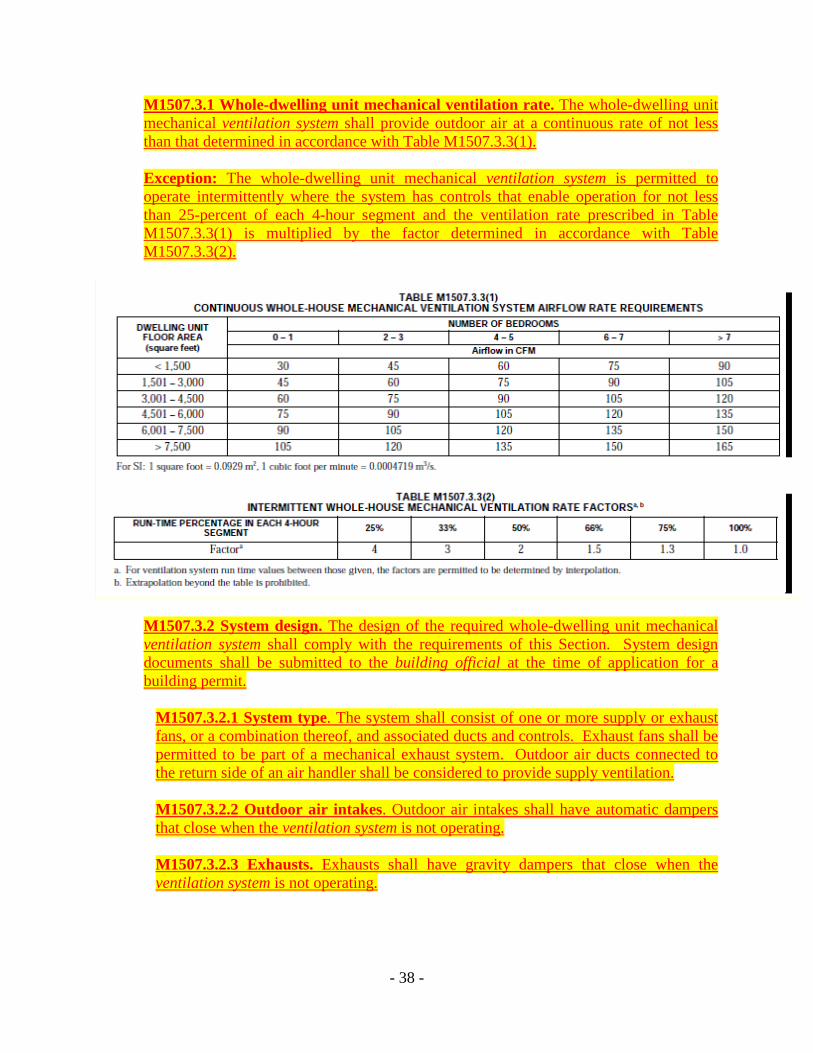
M1507.3.1 Whole-dwelling unit mechanical ventilation rate. The whole-dwelling unit mechanical ventilation system shall provide outdoor air at a continuous rate of not less than that determined in accordance with Table M1507.3.3(1).
Exception: The whole-dwelling unit mechanical ventilation system is permitted to operate intermittently where the system has controls that enable operation for not less than 25-percent of each 4-hour segment and the ventilation rate prescribed in Table M1507.3.3(1) is multiplied by the factor determined in accordance with Table M1507.3.3(2).
M1507.3.2 System design. The design of the required whole-dwelling unit mechanical ventilation system shall comply with the requirements of this Section. System design documents shall be submitted to the building official at the time of application for a building permit.
M1507.3.2.1 System type. The system shall consist of one or more supply or exhaust fans, or a combination thereof, and associated ducts and controls. Exhaust fans shall be permitted to be part of a mechanical exhaust system. Outdoor air ducts connected to the return side of an air handler shall be considered to provide supply ventilation.
M1507.3.2.2 Outdoor air intakes. Outdoor air intakes shall have automatic dampers that close when the ventilation system is not operating.
M1507.3.2.3 Exhausts. Exhausts shall have gravity dampers that close when the ventilation system is not operating.
- 38 -

M1507.3.2.4. Air circulation fan motors. Motors for air circulation fans used in the ventilation system, rated at one-quarter horsepower or greater, shall meet at least one of the following criteria: 1. Where the furnace serves as an air handler for the ventilation system, the furnace shall be certified as an “Electrically Efficient Furnace” by the Air-conditioning, Heating and Refrigeration Institute (AHRI). 2. The blower motor shall be specified as a “Brushless DC” (BL or BLDC) motor by the manufacturer. 3. The blower motor shall be specified as “Brushless Permanent Magnet” (BPM) motor. 4. The blower motor shall be specified as “Electronically Commutated Motor” (ECM)”. 5. The blower shall meet equivalent criteria acceptable to the building official. M1507.3.2.5. System controls. The mechanical ventilation system shall be provided with readily accessible and labeled controls that enable occupant override.
M1507.3.2.6. Sound ratings for fans. Whole-dwelling unit mechanical ventilation fans shall be rated for sound at a maximum of 1.5 sones, in accordance with the procedures of the Home Ventilating. Institute (HVI 915, Procedure for Loudness Rating of Residential Fan Products). Exception: Heating, ventilating and air conditioning air handlers and remote-mounted fans need not meet sound requirements. To be considered for this exception, a remote-mounted fan must be mounted outside the habitable spaces, bathrooms, toilets and hallways, and there must be a least 4 ft (1 m) of ductwork between the fan and the intake grille.
M1507.3.3 System installation. The installation of the whole-dwelling unit mechanical ventilation system and equipment shall be carried out in accordance with the manufacturers’ design requirements and installation instructions.
M1507.3.4 Performance verification. Performance of installed mechanical ventilation systems shall be verified in accordance with Section M1309.”
(91) Section M1601.1 Duct design is hereby amended to read as follows:
“M1601.1 Duct design. Duct systems serving new heating, cooling and ventilation equipment shall be designed and fabricated in accordance with the provisions of this section and ACCA Manual D or other approved methods.”
(92) Section M1601.1.1 Above-ground duct systems Item 7. stud wall cavities is hereby
deleted in its entirety.
- 39 -

7. Stud wall cavities and the spaces between solid floor joists to be used as air plenums shall comply with the following conditions:
7.1. These cavities or spaces shall not be used as a plenum for supply air. 7.2. These cavities or spaces shall not be part of a required fire-resistance-rated
assembly. 7.3. Stud wall cavities shall not convey air from more than one floor level. 7.4. Stud wall cavities and joist-space plenums shall be isolated from adjacent concealed spaces by tight-fitting fireblocking in accordance with Section R602.8. 7.5. Stud wall cavities in the outside walls of building envelope assemblies shall not be utilized as air plenums.
(93) Section, M1601.4.10 Construction debris and contamination is hereby added to read as
follows:
“M1601.4.10 Construction debris and contamination. Mechanical air-handling systems and their related ducts shall be protected from the entrance of dirt, debris, and dust during the construction and installation process. Prior to passing final inspection or issuance of a certificate of occupancy, such systems shall be substantially free of construction-related contaminants.”
(94) Section, M1602.1 Return air is hereby amended to read as:
“M1602.1 Return air. Return air shall be taken from inside the dwelling. Dilution of return air with outdoor air shall be permitted. A return air path shall be provided in all habitable rooms by means of ducts or transfer grills.”
(95) Section G2404.3 (301.3) Listed and labeled is hereby amended by deleting the last
sentence to read as follows:
“G2404.3 (301.3) Listed and labeled. Appliances regulated by this code shall be listed and labeled for the application in which they are used unless otherwise approved in accordance with Section R104.11.” The approval of unlisted appliances in accordance with Section R104.11 shall be based upon approved engineering evaluation.
(96) Section G2406.2 (303.3) Prohibited locations is hereby amended by deleting exceptions
3. and 4.
3. A single wall-mounted unvented room heater is installed in a bathroom and such unvented room heater is equipped as specified in Section G2445.6 and has an input rating not greater than 6,000 Btu/h (1.76 kW). The bathroom shall meet the required volume criteria of Section G2407.5. 4. A single wall-mounted unvented room heater is installed in a bedroom and such unvented room heater is equipped as specified in Section G2445.6 and has an input rating not greater than 10,000 Btu/h (2.93 kW). The bedroom shall meet the required volume criteria of Section G2407.5.
- 40 -

(97) Section G2406.4 (303.5.1) Natural Draft Appliances locations, is hereby added to read as follows:
“G2406.4 Natural Draft Appliances locations. For new buildings and new appliance or new HVAC systems installed within additions, natural draft appliances shall not be located within the building thermal envelope or be located in a space where the only access to that space is from sleeping rooms, bathrooms, toilet rooms, storage closets, or surgical rooms.
Exceptions: 1. Where natural draft appliances are located in an enclosed mechanical room and sealed to air flow from adjoining conditioned area and the following conditions are met:
a. The access to the mechanical room is through a self-closing, gasketed door; b. No other exhaust appliances are located within the mechanical room; c. The mechanical room is provided with outside combustion air as specified in this
code; d. The isolation of the mechanical room from adjoining conditioned areas is verified
with a differential-pressure test performed by approved licensed contractors; e. Such natural draft appliances pass a combustion safety test under worst-case
depressurization conditions in accordance with Building Performance Institute (BPI) Technical Standards for the Heating Professional; and
f. Documentation of satisfactory testing results are submitted to the building official prior to final approval.
2. Natural draft fireplaces that pass a combustion safety test, under worst-case depressurization conditions, performed by approved licensed contractors and conducted in accordance with the Building Performance Institute (BPI) Technical Standards for the Heating Professional, prior to final approval.”
(98) Section G2407.11 (304.11) Combustion air ducts exception to Item, 1 is hereby amended
to read as follows:
“Exception: Within dwellings units, unobstructed stud and joist spaces shall not be prohibited from conveying combustion air, provided that not more than one required fireblock is removed. Where the installation of galvanized steel ducts is not practical due to existing finish materials within dwelling units that are undergoing alteration or reconstruction, unobstructed stud and joist spaces shall not be prohibited from conveying combustion air, provided that not more than one required fireblock is removed.”
This section is hereby further amended by adding item, 9 to read as follows:
“9. All combustion air openings or ducts shall be readily identifiable with an approved label or by other means, warning persons that obstruction of such openings or ducts may
- 41 -

cause fuel-burning equipment to release combustion products and dangerous levels of carbon monoxide into the building.”
(99) Section G2408.1 (305.1) General is hereby amended by deleting the second paragraph
and replacing it to read as follows:
Unlisted appliances approved in accordance with Section G2404.3 shall be limited to uses recommended by the manufacturer and shall be installed in accordance with the manufacturer’s instructions, the provisions of this code and the requirements determined by the code official. “Where natural draft appliances are replaced in existing buildings, all appliances with a draft hood shall pass a combustion safety test under natural conditions, conducted by approved licensed contractors in accordance with the Building Performance Institute (BPI) Technical Standards for the Heating Professional. Such appliances shall also be combustion safety tested under worst-case depressurization conditions, by approved licensed contractors in accordance with Building Performance Institute (BPI) Technical Standards for the Heating Professional. Should an appliance not pass such test, a disclosure form reporting the test results shall be provided to the homeowner. A copy of such disclosure form, signed by the homeowner, shall be submitted to the building official prior to approval.”
(100) Section G2408.2 (305.3) Elevation of ignition source is amended to read as follows:
“G2408.2 (305.3) Elevation of ignition source. Electrical devices, equipment and appliances having an ignition source shall be elevated such that the source of ignition is not less than 18 inches (457 mm) above the floor in hazardous locations and public garages, private garages, repair garages, motor fuel-dispensing facilities and parking garages. For the purpose of this section, rooms or spaces that are not part of the living space of a dwelling unit and that communicate directly with a private garage through openings shall be considered to be part of the private garage.”
Exception: Elevation of the ignition source is not required for appliances that are listed as flammable vapor ignition resistant.
(101) Section G2409.4.4 (308.4.5) Clearance from supply ducts is hereby amended to read as
follows:
“G2409.4.4 (308.4.5) Clearance from supply ducts. Supply air ducts connecting to listed central heating furnaces where the bonnet temperature exceeds 150 oF (68 oC), shall have the same minimum clearance to combustibles as required for the furnace supply plenum for a distance of not less than 3 feet (914 mm) from the supply plenum. Clearance is not required beyond the 3-foot (914 mm) distance.”
(102) Section G2415.9 (404.9) Above-ground piping outdoors is hereby amended to read as
follows:
- 42 -
“G2415.9 (404.9) Above-ground piping outdoors. All piping installed outdoors shall be elevated not less than 31/2 inches (152 mm) 6 inches (152 mm) above ground and where installed across roof surfaces, shall be elevated not less than 31/2 inches (152 mm) above the roof surface. Piping installed above ground, outdoors, and installed across the surface of roofs shall be securely supported and located where it will be protected from physical damage. Where passing through an outside wall, the piping shall also be protected against corrosion by coating or wrapping with an inert material. Where piping is encased in a protective pipe sleeve, the annular space between the piping and the sleeve shall be sealed.”
(103) Section G2415.12 (404.12) Minimum burial depth is hereby amended to read as
follows:
“G2415.12 (404.12) Minimum burial depth. Underground piping systems shall be installed a minimum depth of 12 inches (305 mm) 18 inches (457 mm) below grade, except as provided for in Section G2415.10.1.”
(104) Section G2415.12.1 (404.12.1) Individual outside appliance is hereby amended to read
as follows:
“G2415.12.1 (404.12.1) Individual outside appliances. Individual lines to outside lights, grills or other appliances shall be installed a minimum of 8 inches (203 mm) 18 inches (457 mm) below finished grade.
Exception: Approved materials installed a minimum of 6 inches (152 mm) below finished grade when covered with a concrete slab 3 1/2 inches (88.9 mm) in minimum thickness.”
(105) Section G2415.15 (404.15) Outlet closure is hereby amended to read as follows:
“G2415.15 (404.15) Outlet closures. Gas outlets and fittings which allow for future gas line expansion that do not connect to appliances shall be provided with an approved gas shutoff valve with the end capped gas tight.
Exception: 1. Listed and labeled flush-mounted-type quick-disconnect devices and listed and labeled gas convenience outlets shall be installed in accordance with the manufacturer’s installation instructions. 2. Drip/dirt legs installed at the floor level at appliances.”
(106) Section G2416.1 (405.1) General is hereby amended to read as follows:
“G2416.1 (405.1) General. Changes in direction of pipe rigid metallic pipe specified in G2414.4 shall be made only by the use of fittings and factory bends.” or field bends.
- 43 -
(108) Section G2416.2 (405.2) Metallic pipe is hereby deleted in its entirety.
G2416.2 (405.2) Metallic pipe. Metallic pipe bends shall comply with the following: 1. Bends shall be made only with bending tools and procedures intended for that purpose. 2. All bends shall be smooth and free from buckling, cracks or other evidence of mechanical damage. 3. The longitudinal weld of the pipe shall be near the neutral axis of the bend. 4. Pipe shall not be bent through an arc of more than 90 degrees (1.6 rad). 5. The inside radius of a bend shall be not less than six times the outside diameter of the pipe.
(109) Section G2417.4.1 (406.4.1) Test pressure is hereby amended to read as follows:
“G2417.4.1 (406.4.1) Test pressure. The test pressure to be used shall be not less than one and one-half times the proposed maximum working pressure, but not less than 3 psig (20 kPa gauge), 10 psig (67 kPa gauge) irrespective of design pressure. Where the test pressure exceeds 125 psig (862 kPa gauge), the test pressure shall not exceed a value that produces a hoop stress in the piping greater than 50 percent of the specified minimum yield strength of the pipe.”
(110) Section G2420.5.2 (409.5.2) Vented decorative appliances and room heaters is hereby
amended to read as follows:
“G2420.5.2 (409.5.2) Vented decorative appliances and room heaters. Shutoff valves for vented decorative appliances, room heaters and decorative appliances for installation in vented fireplaces shall be permitted to be installed in an area remote from the appliances where such valves are provided with ready access. Such valves shall be permanently identified and shall serve no other appliance. Remote valves shall be operable on the same floor as the appliance served and within 12 feet (3.658 m) of the appliance as measured along the floor line. The piping from the shutoff valve to within 6 feet (1829 mm) of the appliance shall be designed, sized and installed in accordance with Sections G2412 through G2419.”
(111) Section G2421.3 (410.3) Venting of regulators is hereby amended to read as follows:
“G2421.3 (410.3) Venting of regulators. Pressure regulators that require a vent shall be vented directly to the outdoors. The vent shall be designed to prevent the entry of insects, water, or foreign objects. Vents shall not terminate within 3 feet (0.916 m) of openings into the building. Exception: A vent to the outdoors is not required for regulators equipped with and labeled for utilization with an approved vent-limiting device installed in accordance with the manufacturer’s instructions.”
- 44 -

(112) Section G2425.8 (501.8) Appliances not required to be vented is hereby amended by deleting item 7.
7. Room heaters and other appliances listed for unvented use. (113) Section G2427.5.5.1 (503.5.6.1) Chimney lining is hereby amended by deleting the
exception:
“G2427.5.5.1 (503.5.6.1) Chimney lining. Chimneys shall be lined in accordance with NFPA 211.” Exception: Where an existing chimney complies with Sections G2427.5.5 through G2427.5.5.3 and its sizing is in accordance with Section G2427.5.4, its continued use shall be allowed where the appliance vented by that chimney is replaced by an appliance of similar type, input rating and efficiency.
(114) Section G2427.6.4 (503.6.5) Minimum height is hereby amended by the addition of the
last sentence to read as follows:
“G2427.6.4 (503.6.5) Minimum height. A Type B or L gas vent shall terminate at least 5 feet (1524 mm) in vertical height above the highest connected appliance draft hood or flue collar. A Type B-W gas vent shall terminate at least 12 feet (3658 mm) in vertical height above the bottom of the wall furnace. All gas vents shall terminate a minimum of 22 inches (559 mm) above the surface or grade directly below.”
(115) Section G2439.3 (614.4) Exhaust installation is hereby amended to read as follows:
“G2439.3 (614.4) Exhaust installation. Dryer exhaust ducts for clothes dryers shall terminate on the outside of the building and shall be equipped with a backdraft damper. Dryer exhaust duct terminations shall not be located within 36 inches (914 mm) of exterior openings into conditioned spaces, crawl spaces and attics. Screens shall not be installed at the duct termination. Ducts shall not be connected or installed with sheet metal screws or other fasteners that will obstruct the flow. Clothes dryer exhaust ducts shall not be connected to a vent connector, vent or chimney. Clothes dryer exhaust ducts shall not extend into or through ducts or plenums.”
(116) Section G2439.5.5.2 (614.6.5.2) Manufacturer’s instructions, is hereby deleted in its
entirety.
G2439.5.5.2 (614.6.5.2) Manufacturer’s instructions. The maximum length of the exhaust duct shall be determined by the dryer manufacturer’s installation instructions. The code official shall be provided with a copy of the installation instructions for the make and model of the dryer. Where the exhaust duct is to be concealed, the installation instructions shall be provided to the code official prior to the concealment inspection. In
- 45 -

the absence of fitting equivalent length calculations from the clothes dryer manufacturer, Table G2439.5.5.1 shall be used.
(117) Section G2445 (621), Unvented Room Heaters, is hereby deleted in its entirety.
SECTION G2445 (621) UNVENTED ROOM HEATERS G2445.1 (621.1) General. Unvented room heaters shall be tested in accordance with ANSI Z 21.11.2 and shall be installed in accordance with the conditions of the listing and the manufacturer’s installation instructions.
G2445.2 (621.2) Prohibited use. One or more unvented room heaters shall not be used as the sole source of comfort heating in a dwelling unit. G2445.3 (621.3) Input rating. Unvented room heaters shall not have an input rating in excess of 40,000 Btu/h (11.7 kW). G2445.4 (621.4) Prohibited locations. The location of unvented room heaters shall comply with Section G2406.2. G2445.5 (621.5) Room or space volume. The aggregate input rating of all unvented appliances installed in a room or space shall not exceed 20 Btu/h per cubic foot (0.21 kW/m3) of volume of such room or space. Where the room or space in which the appliance is installed is directly connected to another room or space by a doorway, archway or other opening of comparable size that cannot be closed, the volume of such adjacent room or space shall be permitted to be included in the calculations.
G2445.6 (621.6) Oxygen-depletion safety system. Unvented room heaters shall be equipped with an oxygen-depletion sensitive safety shutoff system. The system shall shut off the gas supply to the main and pilot burners when the oxygen in the surrounding atmosphere is depleted to the percent concentration specified by the manufacturer, but not lower than 18 percent. The system shall not incorporate field adjustment means capable of changing the set point at which the system acts to shut off the gas supply to the room heater. G2445.7 (621.7) Unvented decorative room heaters. An unvented decorative room heater shall not be installed in a factory-built fireplace unless the fireplace system has been specifically tested, listed and labeled for such use in accordance with UL 127.
G2445.7.1 (621.7.1) Ventless firebox enclosures. Ventless firebox enclosures used with unvented decorative room heaters shall be listed as complying with ANSI Z21.91.
(118) Section G2447.6 (623.8) Kitchens with gas cooking is hereby added to read as follows:
“G2447.6 Kitchens with gas cooking. Residential kitchens with gas cooking appliances shall be supplied with an exhaust system vented to the outside. Ducts serving kitchen
- 46 -

exhaust systems shall not terminate in an attic or crawl space or areas inside the building and shall not induce or create a negative pressure in excess of negative 3 Pa or adversely affect gravity-vented appliances.”
(119) Section G2451.3 (630.3) Combustion and ventilation air is hereby added to read as
follows:
“G2451.3 (630.3) Combustion and ventilation air. Where infrared heaters are installed, natural or mechanical means shall provide outdoor ventilation air at a rate of not less than 4 cfm per 1,000 Btu/h (0.38 m3/min/kW) of the aggregate input rating of all such heaters installed in the space. Exhaust openings for removing flue products shall be above the level of the heaters.”
(120) Section G2454 (636) Outdoor Decorative Appliances is hereby amended to read as
follows:
“G2454.1 (636) General. Permanently fixed-in-place outdoor decorative appliances shall be tested in accordance with ANSI Z21.97 and shall be provided with a flame safeguard device and be installed in accordance with the manufacturer’s instructions. Appliances shall not be located beneath or within 10 feet (3048 mm) of combustible construction.”
(121) Section P2503.5.1 Rough Plumbing is hereby amended to read as follows:
“P2503.5.1 Rough plumbing. DWV systems shall be tested on completion of the rough piping installation by water or for piping systems other than plastic, by air with no evidence of leakage. Either test shall be applied to the drainage system in its entirety or in sections after rough piping has been installed, as follows:
1. Water test. Each section shall be filled with water to a point not less than 10 feet (3048 mm) above the highest fitting connection in that section, or to the highest point in the completed system. Water shall be held in the section under test for a period of 15 minutes. The system shall prove leak free by visual inspection. 2. Air test. The portion under test shall be maintained at a gauge pressure of 5 pounds per square inch (psi) (34 kPa) or 10 inches of mercury column (34 kPa). This pressure shall be held without introduction of additional air for a period of 15 minutes.”
(122) Section P2903.2 Maximum flow and water consumption is hereby amended to read as
follows:
“P2903.2 Maximum flow and water consumption. The maximum water consumption flow rates and quantities for all plumbing fixtures and fixture fittings shall be in accordance with Table P2903.2 and such fixtures shall be Environmental Protection Agency (EPA) WaterSense® labeled fixtures or such fixtures and fittings that provide the equivalent maximum flow rates.”
(123) Table P2903.2 is hereby amended to read as follows:
- 47 -

“Table P2903.2 Maximum Flow Rates and Consumption For Plumbing Fixtures and Fixture Fittings b
PLUMBING FIXTURE OR FIXTURE FITTING
MAXIMUM FLOW RATES
Lavatory faucet
2.2 gpm at 60 psi 1.5 gpm at 60 psi
Shower heada
2.5 gpm at 80 psi 2.0 gpm at 80 psi
Sink faucet
2.2 gpm at 60 psi 1.8 gpm at 60 psi
Water closet
1.6 gallons per flushing cycle 1.28 gallons per flushing cycle, with minimum MaP threshold of 350 grams
For SI: 1 gallon per minute (gpm) = 3.785 L/m. 1 pound per square inch (psi) = 6.895 kPa
2 A handheld shower spray is also a shower head
3 Consumption tolerances shall be determined from referenced standards.”
(124) Chapter 44 Referenced Standards is hereby amended by adding the following additional
referenced standards in alphabetical sequence:
Add the following referenced title standard to ACCA; ANSI/ACCA QI 5-2007 HVAC Quality Installation Specification. Referenced in Amended 2012 IRC Section M1309 Performance verification Installation Masters™ Testing and Certification Program Referenced in Amended 2012 IRC Section R703.8.1 Fenestration installation CDPH California Department of Public Health
1615 Capitol Avenue Sacramento, CA 95814
CDPH 01350 Standard Method for Testing VOC emissions from indoor sources Referenced in Amended 2012 IRC Section R325.1 Low-volatile organic compound
(VOC) materials.”
“FSC Forest Stewardship Council U.S. (FSC-US) 212 Third Avenue North, Suite 504
Minneapolis, MN 55401”
“GEI GREENGUARD Environmental Institute 2211 Newmarket Parkway, Suite 110 Marietta, GA 30067
GGPS.001.GREENGUARD IAQ Standard for Building Materials, Finishes and Furnishings Referenced in Amended 2012 IRC Section R325.1 Low-volatile organic compound (VOC) materials.”
- 48 -
“Green Seal® 1001 Connecticut Avenue, NW Suite 827
Washington, DC 20036-5525 GS-11 Paintings and Coatings GS-43 Recycled Content Latex Paints Referenced in Amended 2012 IRC Section R325.1 Low-volatile organic compound
(VOC) materials.”
“HVI Home Ventilating Institute 1000 N Rand Rd, Ste 214 Wauconda, IL 60084 USA HVI referenced standard HVI 915, Procedure for Loudness Rating of Residential Fan Products Referenced in Amended 2012 IRC Section M1507.4.2.6. Sound ratings for fans.” “IDA International Dark-Sky Association 3225 N. First Avenue Tucson, Arizona 85719 IDA fixture seal of approval (FSA) third-party certification for luminaires that minimize glare, reduce light trespass, and don’t pollute the night sky. http://www.darksky.org/ http://www.darksky.org/outdoorlighting/mlo http://www.darksky.org/outdoorlighting/about-fsa “RESNET® Mortgage Industry National Home Energy Rating Systems Standards Residential Energy Services Network, Inc. P.O. Box 4561 Oceanside, CA 92052-4561 http://resnet.us
RESNET® reference standard Grade I and Grade II Insulation Referenced in Amended 2012 IRC Section N1102.2 Specific insulation requirements.
(125) APPENDIX E, MANUFACTURED HOUSING USED AS DWELLINGS, is hereby
adopted in its entirety. (126) APPENDIX F, RADON CONTROL METHODS, is hereby adopted and amended in its
entirety to read as follows:
APPENDIX F RADON CONTROL METHODS SECTION AF101 SCOPE AF101.1 General. This appendix contains requirements for new construction in jurisdictions where radon-resistant construction is required. Inclusion of this appendix by
- 49 -

jurisdictions shall be determined through the use of locally available data or determination of Zone 1 designation in Figure AF101 and Table AF101(1). SECTION AF102 DEFINITIONS AF102.1 General. For the purpose of these requirements, the terms used shall be defined as follows: DRAIN TILE LOOP. A continuous length of drain tile or perforated pipe extending around all or part of the internal or external perimeter of a basement or crawl space footing. RADON GAS. A naturally occurring, chemically inert, radioactive gas that is not detectable by human senses. As a gas, it can move readily through particles of soil and rock, and can accumulate under the slabs and foundations of homes where it can easily enter into the living space through construction cracks and openings. SOIL-GAS-RETARDER. A continuous membrane of 6-mil (0.15 mm) polyethylene or other equivalent material used to retard the flow of soil gases into a building. SUBMEMBRANE DEPRESSURIZATION SYSTEM. A system designed to achieve lower sub membrane air pressure relative to crawl space air pressure by use of a vent drawing air from beneath the soil-gas-retarder membrane SUBSLAB DEPRESSURIZATION SYSTEM (Active). A system designed to achieve lower subslab air pressure relative to indoor air pressure by use of a fan-powered vent drawing air from beneath the slab. SUBSLAB DEPRESSURIZATION SYSTEM (Passive). A system designed to achieve lower subslab air pressure relative to indoor air pressure by use of a vent pipe routed through the conditioned space of a building and connecting the subslab area with outdoor air, thereby relying on the convective flow of air upward in the vent to draw air from beneath the slab. SECTION AF103 REQUIREMENTS AF103.1 General. The following construction techniques are intended to resist radon entry and prepare the building for post-construction radon mitigation, if necessary (see Figure AF102). These techniques are required in areas where designated by the jurisdiction. AF103.2 Subfloor preparation. A layer of gas-permeable material shall be placed under all concrete slabs and other floor systems that directly contact the ground and are within the walls of the living spaces of the building, to facilitate future installation of a subslab depressurization system, if needed. The gas-permeable layer shall consist of one of the following: 1. A uniform layer of clean aggregate, a minimum of 4 inches (102 mm) thick. The aggregate shall consist of material that will pass through a 2-inch (51 mm) sieve and be retained by a 1/4-inch (6.4 mm) sieve. 2. A uniform layer of sand (native or fill), a minimum of 4 inches (102 mm) thick, overlain by a layer or strips of geotextile drainage matting designed to allow the lateral flow of soil gases. 3. Other materials, systems or floor designs with demonstrated capability to permit depressurization across the entire subfloor area.
- 50 -

AF103.3 Soil-gas-retarder. A minimum 6-mil (0.15 mm) [or 3-mil (0.075 mm) cross-laminated] polyethylene or equivalent flexible sheeting material shall be placed on top of the gas-permeable layer prior to casting the slab or placing the floor assembly to serve as a soil-gas-retarder by bridging any cracks that develop in the slab or floor assembly, and to prevent concrete from entering the void spaces in the aggregate base material. The sheeting shall cover the entire floor area with separate sections of sheeting lapped at least 12 inches (305 mm). The sheeting shall fit closely around any pipe, wire or other penetrations of the material. All punctures or tears in the material shall be sealed or covered with additional sheeting. AF103.4 Entry routes. Potential radon entry routes shall be closed in accordance with Sections AF103.4.1 through AF103.4.10. AF103.4.1 Floor openings. Openings around bathtubs, showers, water closets, pipes, wires or other objects that penetrate concrete slabs, or other floor assemblies, shall be filled with a polyurethane caulk or equivalent sealant applied in accordance with the manufacturer’s recommendations. AF103.4.2 Concrete joints. All control joints, isolation joints, construction joints, and any other joints in concrete slabs or between slabs and foundation walls shall be sealed with a caulk or sealant. Gaps and joints shall be cleared of loose material and filled with polyurethane caulk or other elastomeric sealant recommendations. AF103.4.3 Condensate drains. Condensate drains shall be trapped or routed through nonperforated pipe to daylight. AF103.4.4 Sumps. Sump pits open to soil or serving as the termination point for subslab or exterior drain tile loops shall be covered with a gasketed or otherwise sealed lid. Sumps used as the suction point in a subslab depressurization system shall have a lid designed to accommodate the vent pipe. Sumps used as a floor drain shall have a lid equipped with a trapped inlet. AF103.4.5 Foundation walls. Hollow block masonry foundation walls shall be constructed with either a continuous course of solid masonry, one course of masonry grouted solid, or a solid concrete beam at or above finished ground surface to prevent the passage of air from the interior of the wall into the living space. Where a brick veneer or other masonry ledge is installed, the course immediately below that ledge shall be sealed. Joints, cracks or other openings around all penetrations of both exterior and interior surfaces of masonry block or wood foundation walls below the ground surface shall be filled with polyurethane caulk or equivalent sealant. Penetrations of concrete walls shall be filled. AF103.4.6 Dampproofing. The exterior surfaces of portions of concrete and masonry block walls below the ground surface shall be dampproofed in accordance with Section R406. AF103.4.7 Air-handling units. Air-handling units in crawl spaces shall be sealed to prevent air from being drawn into the unit. Exception: Units with gasketed seams or units that are otherwise sealed by the manufacturer to prevent leakage. AF103.4.8 Ducts. Ductwork passing through or beneath a slab shall be of seamless material unless the air-handling system is designed to maintain continuous positive pressure within such ducting. Joints in such ductwork shall be sealed to prevent air
- 51 -
leakage. Ductwork located in crawl spaces shall have all seams and joints sealed by closure systems in accordance with Section M1601.4.1. AF103.4.9 Crawl space floors. Openings around all penetrations through floors above crawl spaces shall be caulked or otherwise filled to prevent air leakage. AF103.4.10 Crawl space access. Access doors and other openings or penetrations between basements and adjoining crawl spaces shall be closed, gasketed or otherwise filled to prevent air leakage. AF103.5 Passive submembrane depressurization system. In buildings with crawl space foundations, the following components of a passive submembrane depressurization system shall be installed during construction. Exception: Buildings in which an approved mechanical crawl space ventilation system or other equivalent system is installed. AF103.5.1 Ventilation. Crawl spaces shall be provided with vents to the exterior of the building. The minimum net area of ventilation openings shall comply with Section R408.1. AF103.5.2 Soil-gas-retarder. The soil in crawl spaces shall be covered with a continuous layer of minimum 6- mil (0.15 mm) polyethylene soil-gas-retarder. The ground cover shall be lapped a minimum of 12 inches (305 mm) at joints and shall extend to all foundation walls enclosing the crawl space area. AF103.5.3 Vent pipe. A plumbing tee or other approved connection shall be inserted horizontally beneath the sheeting and connected to a 3- or 4-inch-diameter (76 or 102 mm) fitting with a vertical vent pipe installed through the sheeting. The vent pipe shall be extended up through the building floors, and terminate at least 12 inches (305 mm) above the roof in a location at least 10 feet (3048 mm) away from any window or other opening into the conditioned spaces of the building that is less than 2 feet (610 mm) below the exhaust point, and 10 feet (3048 mm) from any window or other opening in adjoining or adjacent buildings. AF103.6 Passive subslab depressurization system. In basement or slab-on-grade buildings, the following components of a passive subslab depressurization system shall be installed during construction. AF103.6.1 Vent pipe. A minimum 3-inch-diameter (76 mm) ABS, PVC or equivalent gas-tight pipe shall be embedded vertically into the subslab aggregate or other permeable material before the slab is cast. A “T” fitting or equivalent method shall be used to ensure that the pipe opening remains within the subslab permeable material. Alternatively, the 3-inch (76 mm) pipe shall be inserted directly into an interior perimeter drain tile loop or through a sealed sump cover where the sump is exposed to the subslab aggregate or connected to it through a drainage system. The pipe shall be extended up through the building floors, and terminate at least 12 inches (305 mm) above the surface of the roof in a location at least 10 feet (3048 mm) away from any window or other opening into the conditioned spaces of the building that is less than 2 feet (610 mm) below the exhaust point, and 10 feet (3048 mm) from any window or other opening in adjoining or adjacent buildings. AF103.6.2 Multiple vent pipes. In buildings where interior footings or other barriers separate the subslab aggregate or other gas-permeable material, each area shall be fitted
- 52 -

with an individual vent pipe. Vent pipes shall connect to a single vent that terminates above the roof or each individual vent pipe shall terminate separately above the roof. AF103.7 Vent pipe drainage. All components of the radon vent pipe system shall be installed to provide positive drainage to the ground beneath the slab or soil-gas-retarder. AF103.8 Vent pipe accessibility. Radon vent pipes shall be accessible for future fan installation through an attic or other area outside the habitable space. Exception: The radon vent pipe need not be accessible in an attic space where an approved roof-top electrical supply is provided for future use. AF103.9 Vent pipe identification. All exposed and visible interior radon vent pipes shall be identified with at least one label on each floor and in accessible attics. The label shall read: “Radon Reduction System.” AF103.10 Combination foundations. Combination basement/ crawl space or slab-on-grade/crawl space foundations shall have separate radon vent pipes installed in each type of foundation area. Each radon vent pipe shall terminate above the roof or shall be connected to a single vent that terminates above the roof. AF103.11 Building depressurization. Joints in air ducts and plenums in unconditioned spaces shall meet the requirements of Section M1601. Thermal envelope air infiltration requirements shall comply with the energy conservation provisions in Chapter 11. Fireblocking shall meet the requirements contained in Section R302.11. AF103.12 Power source. To provide for future installation of an active submembrane or subslab depressurization system, an electrical circuit terminated in an approved box shall be installed during construction in the attic or other anticipated location of vent pipe fans. An electrical supply shall also be accessible in anticipated locations of system failure alarms.
““AAppppeennddiixx FF –– RRAADDOONN CCOONNTTRROOLL MMEETTHHOODDSS
SECTION AF101 TITLE, SCOPE AND PURPOSE
AF101.1 Title. These provisions shall be known as Appendix Chapter F, the FORT COLLINS RADON RESISTANT CONSTRUCTION CODE FOR ONE- AND TWO-FAMILY DWELLINGS, and shall be cited as such and will be referred to herein as “this appendix.”
AF101.2 Scope. The provisions of this appendix shall apply to new one- and two-family dwellings completely separated from adjacent dwellings by unobstructed physical space (detached) and multiple, attached single-family dwellings (townhouses) not more than three stories in height, with each townhouse having its own separate means of egress.
AF01.3 Purpose. The purpose of this appendix is to provide minimum requirements to enhance the public safety, health and general welfare, through construction methods designed and installed to resist entry of radon gas into the occupied spaces of buildings regulated by this appendix.
SECTION AF102
- 53 -

DEFINITIONS
AF102.1 General. For the purpose of these requirements, the terms used shall be defined as follows: DWELLING UNIT, SINGLE-FAMILY DETACHED. An independent building completely separated from adjacent dwellings by unobstructed physical space, exclusively containing one dwelling unit located entirely on a separately recorded and platted parcel of land (site) bounded by property lines, which parcel is deeded exclusively for such single-family dwelling. DWELLING UNIT, TWO-FAMILY DETACHED. An independent building completely separated from adjacent dwellings by unobstructed physical space, exclusively containing two dwelling units located entirely on a separately recorded and platted parcel of land (site) bounded by property lines, which parcel is deeded exclusively for such two-family dwelling. FOUNDATION DRAIN SYSTEM. A continuous length of drain tile, perforated pipe, or filter mat extending around all or part of the internal or external perimeter of a basement or crawl space footing designed to collect and drain away excess subsurface water. RADON. A naturally occurring, chemically inert, radioactive gas that is not detectable by human senses, that can move readily through particles of soil and rock, and that can accumulate under the slabs and foundations of homes where it can easily enter the living space through construction cracks and openings. SOIL-GAS-RETARDER. A continuous membrane of 3-mil (0.075 mm) cross-linked polyethylene or other equivalent material used to retard the flow of soil gases into a building. SUBFLOOR. A concrete slab or other approved permanent floor system that directly contacts the ground and is within the walls of the living spaces of the building. SUB-MEMBRANE DEPRESSURIZATION SYSTEM. A system designed to achieve lower sub-membrane air pressure relative to crawl space air pressure by use of a vent drawing air from beneath the soil-gas-retarder membrane. SUB-SLAB DEPRESSURIZATION SYSTEM (Passive). A system designed to achieve lower sub-slab air pressure relative to indoor air pressure by use of a vent pipe routed through the conditioned space of a building and connecting the sub-slab area with outdoor air, thereby relying on the convective flow of air upward in the vent to draw air from beneath the slab. TOWNHOUSE. A single-family dwelling unit constructed as part of a group of two or more attached individual dwelling units, each of which is separated from the other from the foundation to the roof and is located entirely on a separately recorded and platted parcel of
- 54 -

land (site) bounded by property lines, which parcel is deeded exclusively for such single-family dwelling.
SECTION AF103 REQUIREMENTS
AF103.1 General. The following required construction methods are intended to resist radon entry and prepare the building for post-construction radon mitigation (see Figure AF102). AF103.2 Subfloor preparation. A layer of gas-permeable material shall be placed under all subfloors. The gas-permeable layer shall consist of one of the following methods except that, where fills of aggregate size less than that described in Method 1are used beneath a slab, Method 2,3, 4, or 5 must be used.
1. A uniform layer of clean aggregate, a minimum of 4 inches (102 mm) thick. The aggregate shall consist of material that will pass through a 2-inch (51 mm) sieve and be retained by a 1/4 -inch (6.4 mm) sieve. In buildings where interior footings or other barriers separate sub-grade areas, penetrations through the interior footing or barrier equal to a minimum of 12 square inches (0.094 m2) per 10 feet (3.048 m) of barrier length shall be provided. A minimum of two penetrations shall be provided per separation and be evenly spaced along the separation.
EXCEPTION: In buildings where interior footings or other barriers separate the sub-grade area, separate
radon vent pipes may be installed for each sub-grade area as specified in Section AF103.5.2 in lieu of penetrations through the barrier.
2. A foundation drain pipe system installed under concrete floor slab areas less than
2,000 square feet (186 m2), consisting of a continuous loop of minimum 3-inch (76 mm.) diameter perforated pipe shall be laid in the sub-grade with the top of the pipe located 1 inch (25.4 mm) below the concrete slab. The pipe may be rigid or flexible but shall have perforations fully around the circumference with a free air space equal to 1.83 square inches per square foot (127 cm2/ m2) of exterior pipe surface area. Such pipe shall be wrapped with approved filter material to prevent blocking of pipe perforations. The pipe loop shall be located inside of the exterior perimeter foundation walls not more than 12 inches (305 mm) from the perimeter foundation walls. In buildings where interior footings or other barriers separate the sub-grade area, the loop of pipe shall penetrate or pass beneath such interior footings or barriers. For slab areas greater than 2,000 square feet (186 m2) but less than 4,000 square feet (372 m2), the preceding configuration may be used provided a minimum of 4-inch diameter (102 mm) pipe is installed. Slabs in excess of 4,000 square feet (372 m2) shall have under them separate loops for every additional 2,000 square feet (186 m2) of slab area when 3-inch (76 mm) diameter pipe is used; or slabs may have separate loops provided for each additional increment in area between 2,000 square feet (186 m2) and 4,000 square feet (372 m2) when 4-inch (102 mm) diameter pipe is used.
- 55 -

3. A foundation drain soil gas collection mat system installed under concrete floor
slab areas of 2,000 square feet (186 m2) or less, consisting of a continuous rectilinear loop of soil gas collection mat or drainage mat having minimum dimensions of 1 inch in height by 12 inches in width (25.4 mm in height x 305 mm in width) and a nominal cross-sectional air flow area of 12 square inches (0.0078 m2) may be laid on top of the sub-grade. The mat shall be constructed of a matrix that allows for the movement of air through it and be capable of supporting the concrete placed upon it. The matrix shall be covered by approved filter material on all four sides to prevent dirt or concrete from entering the matrix. All breaches and joints in the filter material shall be repaired prior to the placement of the slab. The loop shall be located inside the exterior perimeter foundation walls and within 12 inches (305 mm) from the perimeter foundation walls. In buildings where interior footings or other barriers separate the sub-grade area, the mat shall penetrate these interior footings or barriers to form a continuous loop around the exterior perimeter. Slabs larger than 2,000 square feet (186 m2) but less than 4,000 square feet (372 m2) shall have under them an additional strip of mat that bisects the loop forming two areas approximately equally divided by the two halves of the rectilinear loop. Slabs larger than 4,000 square feet (372 m2) shall have separate loops for each 2,000 (186 m2) square feet; or for each 4,000 square feet (372 m2) if a loop is bisected as specified in the preceding configuration.
4. A uniform layer of sand (native or fill), a minimum of 4 inches (102 mm) thick, overlain by a layer or strips of geo-textile drainage matting designed to allow the lateral flow of soil gases.
5. Other materials, systems or floor designs with demonstrated capability to permit depressurization across the entire sub-floor area. AF103.3 Entry routes. Potential radon entry routes shall be closed in accordance with Sections AF103.3.1 through AF103.3.11.
AF103.3.1 Floor openings. Openings around bathtubs, showers, water closets, pipes, wires or other objects that penetrate concrete slabs or other floor assemblies shall be filled with a polyurethane caulk or equivalent sealant applied in accordance with the manufacturer’s recommendations.
AF103.3.2 Concrete joints. All control joints, isolation joints, construction joints and
any other joints in concrete slabs or between slabs and foundation walls shall be sealed with a caulk or sealant. Gaps and joints shall be cleared of loose material and filled with polyurethane caulk or other elastomeric sealant applied in accordance with the manufacturer’s recommendations.
- 56 -

AF103.3.3 Condensate drains. Condensate drains shall be trapped or routed through non- perforated pipe to daylight.
AF103.3.4 Sumps. Sump pits open to soil or serving as the termination point for sub-
slab or exterior drain tile loops shall be covered with a gasketed or otherwise sealed lid. Sumps used as the suction point in a sub-slab depressurization system shall have a lid designed to accommodate the vent pipe. Sumps used as a floor drain shall have a lid equipped with a trapped inlet and view port.
AF103.3.5 Foundation walls. Hollow block masonry foundation walls shall be
constructed with either a continuous course of solid masonry, one course of masonry grouted solid, or a solid concrete beam at or above finished ground surface to prevent passage of air from the interior of the wall into the living space. Where a brick veneer or other masonry ledge is installed, the course immediately below that ledge shall be sealed. Joints, cracks or other openings around all penetrations of both exterior and interior surfaces of masonry block or wood foundation walls below the ground surface shall be filled with polyurethane caulk or equivalent sealant. Penetrations of concrete walls shall be filled.
AF103.3.6 Dampproofing. The exterior surfaces of portions of concrete and masonry
block walls below the ground surface shall be damp-proofed in accordance with Section R406 of this appendix.
AF103.3.7 Air-handling units. Air-handling units in crawl spaces shall be sealed to
prevent air from being drawn into the unit. Exception: Units with gasketed seams or units that are otherwise sealed by the manufacturer to prevent leakage.
AF103.3.8 Ducts. Ductwork passing through or beneath a slab shall be of seamless material unless the air-handling system is designed to maintain continuous positive pressure within such ducting. Joints in such ductwork shall be sealed to prevent air leakage. Ductwork located in crawl spaces shall have all seams and joints sealed by closure systems in accordance with Section M1601.3.1.
AF103.4 Sub-membrane depressurization system. In buildings with interior structural floors directly above under-floor spaces containing exposed soil surfaces that are not protected by a sub-slab depressurization system, the following components of a sub-membrane depressurization system shall be installed during construction. Exception: Buildings in which an approved mechanical ventilation system complying with Section R408 or such other equivalent system that provides equivalent depressurization across the entire sub-membrane area as determined by the building official is installed in the under-floor spaces.
- 57 -

AF103.4.1Ventilation. Crawl spaces and similar under-floor spaces shall be provided with ventilation complying with Section R408. AF103.4.2 Soil-gas-retarder. The exposed soil in under-floor spaces shall be covered with a continuous layer of soil-gas-retarder. Such ground cover joints shall overlap 6 inches (152 mm) and be sealed or taped. The edges of the ground cover shall extend a minimum of 6 inches (152mm) up onto all foundation walls enclosing the under-floor space and shall be attached and sealed to foundation walls in an approved manner. AF103.4.3 Vent pipe riser. A plumbing tee or other approved connection shall be inserted horizontally beneath the sheeting and connected to a 3- or 4-inch-diameter (76 mm or 102 mm) fitting with a vertical vent pipe installed through the sheeting. The vent pipe shall be extended up through the building floors, and shall terminate at least 12 inches (305 mm) above the roof in a location at least 10 feet (3.048 m) away from any window or other opening into the conditioned spaces of the building at a point that is less than 2 feet (0.610 m) below the exhaust point and 10 feet (3.048 m) from any window or other opening in adjoining or adjacent buildings.
AF103.5 Sub-slab depressurization system. The following components of a sub-slab depressurization system shall be installed during construction under basement or slab-on-grade floors.
AF103.5.1 Vent pipe riser. A minimum 3-inch-diameter (76 mm) ABS or PVC DWV pipe, or equivalent gas-tight pipe shall be embedded vertically into the sub-slab aggregate or other permeable material before the slab is cast. A “T” fitting or equivalent method shall be used to ensure that the pipe opening remains within the sub-slab permeable material. Alternatively, the 3-inch (76 mm) pipe shall be inserted directly into an interior perimeter drain tile loop or through a sealed sump cover where the sump is exposed to the sub-slab aggregate or connected to it through a drainage system. All vent pipes shall be extended up through the building floors and terminate at least 12 inches (305 mm) above the surface of the roof in a location at least 10 feet (3.048 m) away from any window, air intake, or other opening into the conditioned spaces of the building that is less than 2 feet (0.610 m) below the exhaust point, and 10 feet (3.048 m) from any window or other opening in adjoining or adjacent buildings. The discharge end of vent pipe terminations shall be unobstructed and protected from small animal entry with a corrosion-resistant screen having openings between .25 inch (6.4 mm) and .5 inch (12.7 mm).
AF103.5.2 Multiple vent pipes. In buildings where interior footings or other barriers separate the sub-slab aggregate or other gas-permeable material, each area shall be fitted with an individual vent pipe. Vent pipes shall connect to a single vent that terminates above the roof or, in the alternative, each individual vent pipe shall terminate separately above the roof.
- 58 -

AF103.6 Vent pipe drainage. All components of the radon vent pipe system shall be installed to provide positive drainage to the ground beneath the slab or soil-gas retarder.
AF103.7 Vent pipe accessibility. Radon vent pipes shall be accessible for fan installation through an attic or other area outside the habitable space.
Exception: The radon vent pipe need not be accessible in an attic space where an approved roof-top electrical supply is provided.
AF103.8 Vent pipe identification and notification. All exposed and visible interior radon vent pipes shall be conspicuously identified with at least one label on each floor and in attics provided with access openings. The label shall read substantially as follows: Radon Reduction System. In addition to the preceding label, a notice shall be placed in a conspicuous area near the vent pipe that states the following:
This radon reduction system is not required to be tested and is a “passive” system, relying entirely on natural ventilation. Occupants are advised to test for radon and take remedial action as necessary by installing a continuously-operating fan located in the vent pipe (access typically provided in the attic) and connected to the nearby provided electrical outlet. Call 1-800-767-radon for more information.
AF103.9 Combination foundations. Combination basement/crawl space or slab-on-grade/crawl space foundations shall have separate radon vent pipes installed in each type of foundation area. Each radon vent pipe shall terminate above the roof or shall be connected to a single vent that terminates above the roof.
AF103.10 Building depressurization. Joints in air ducts and plenums in unconditioned spaces shall be substantially air tight and permanently sealed with an approved sealant, mastic, or other approved methods. Thermal envelope air infiltration requirements shall comply with the energy conservation provisions in the energy conservation code currently enacted by the City. Firestopping shall be in conformance with the most recent general building code enacted by the City or meet the requirements contained in Section R602.8.
AF103.11 Provisions for future depressurization fan installation. Permanent provisions shall be made for the future installation of an in-line fan to be connected to every radon vent pipe. Such designated fan locations shall be outside of the conditioned envelope of the building, such as in the attic, garage and similar locations, excluding crawl spaces and other interior under-floor spaces. Designated locations shall accommodate an unobstructed permanent cylindrical space with the following minimum dimensions: 12 inches (305 mm) measured radially around the radon vent pipe along a vertical distance of 30 inches (760 mm). Designated fan locations shall be permanently accessible for servicing and maintenance. An electrical circuit shall be provided within 4 feet (1.219 m) of and within sight from designated fan locations. Such circuit shall have a means of positive disconnection and be terminated in an approved electrical outlet in accordance with the applicable current electric code.
- 59 -

AF103.12 Depressurization fan system activation. When a passive system constructed in accordance with this appendix is to be converted to an active system, an approved in-line fan shall be installed in a designated fan location as specified in Section AF103.11.1. Additionally, an approved permanent electric light fixture and in-line pipe couplings that facilitate fan replacement shall be provided. The in-line fan shall be designed to operate continuously for a period of not less than five years and have a minimum air-flow rating as established by the building official. A readily accessible manometer or other approved warning device that notifies occupants of a fan malfunction by a visible or audible signal shall be installed within the dwelling unit. A separate permit shall be required for installation of such fan when it is not installed at the time the building is originally approved for occupancy.”
(127) APPENDIX G, SWIMMING POOLS, SPAS, AND HOT TUBS, is hereby adopted in its
entirety. (128) Section AG 105.6 Barrier around decorative pools, fountains, and ponds is hereby
added to read as follows:
“AG105.6 Barriers around decorative pools, fountains, and ponds. Decorative pools, fountains, and ponds which can contain water deeper than 24 inches (610 mm), shall be protected by barriers installed in accordance with section AG105.2.”
(129) APPENDIX H, PATIO COVERS, is hereby adopted in its entirety. (130) APPENDIX J, EXISTING BUILDINGS AND STRUCTURES, is hereby adopted in its
entirety. (131) APPENDIX M, HOME DAY-CARE R-3 OCCUPANCIES, is hereby adopted in its
entirety.
Introduced, considered favorably on first reading, and ordered published this 21st day of January, A.D. 2014, and to be presented for final passage on the 4th day of February, A.D. 2014.
__________________________________ Mayor ATTEST: _______________________________ City Clerk
- 60 -
Passed and adopted on final reading on the 4th day of February, A.D. 2014.
__________________________________ Mayor ATTEST: _______________________________ City Clerk
- 61 -