2010 - Georgia Department of Education · above will take precedence over the previous wording...
112
2010 Georgia School Bus Specifications Georgia Department of Education Kathy Cox, State Superintendent of Schools January 15, 2010 All Rights Reserved
-
Upload
phungkhanh -
Category
Documents
-
view
216 -
download
3
Transcript of 2010 - Georgia Department of Education · above will take precedence over the previous wording...

2010
Georgia School Bus Specifications
Georgia Department of Education Kathy Cox, State Superintendent of Schools
January 15, 2010 All Rights Reserved
Georgia Department of Education Kathy Cox, State Superintendent of Schools
January 15, 2010 • Page 2 of 112 All Rights Reserved
Forward The School Bus Specifications adopted by the 2005 National Conference on School Transportation, the Federal Motor Vehicle Safety Standards (FMVSS), Society of Automotive Engineers (SAE) and the American Society of Testing Materials (ASTM) were used as guides by the Georgia Department of Education Transportation Specification Committee in developing the revised minimum specifications for school bus chassis and school bus bodies. These specifications are divided into nine sections:
1. School Bus Definitions 2. Chassis and Body Specifications – Type A Bus – Small School Bus 3. Chassis Specifications – Conventional and Transit School Buses – Types B, C, and D 4. Body Specifications – Conventional and Transit Schools Buses – Types B, C, and D 5. Body Specifications – Exceptional Child Bus
5.1 Bus Bodies with Power Lifts 5.2 Bus Bodies without Power Lifts
6. Vendor Requirements 7. Multi Function School Activity Bus 8. Accessories 9. Appendices
Effective Date and Bidder Requirements These specifications apply respectively to new school buses with a bid date of January 15, 2010 (the day after DOE Board adoption) or later. Any variation from the specifications without prior approval of the Pupil Transportation Division of the Department of Education is prohibited. The responsibility for compliance with the school bus specifications listed rests with dealers and manufacturers bidding and selling within the State of Georgia. By signing the bid for the local school system, the school bus supplier (seller) certifies that the complete school bus being offered meets or exceeds all requirements and conditions as stated in the National Specifications except where superseded by Georgia School Bus Specifications. The local school system’s superintendent shall notify the Department of Education in writing of any material or construction defects found on new school bus purchases (Board Rule 160-5-3-.03). In the event a dealer or manufacturer sells a school bus in the State of Georgia that does not conform to any or all of the required specifications, a general notice will be sent by the Department of Education Pupil Transportation Division to all school districts advising that such equipment supplied by said dealer or manufacturer does not meet specifications in that area. A copy of the notice will be sent to the dealer or manufacturer and will remain in effect until full compliance by the dealer or manufacturer is assured. The burden of proof for compliance with these specifications shall be the responsibility of the school bus supplier. NOTE: The wording found in this paragraph of the 2008 Georgia School Bus Specifications Manual will hereby

Georgia Department of Education Kathy Cox, State Superintendent of Schools
January 15, 2010 • Page 3 of 112 All Rights Reserved
supersede the previous wording in 2006 and 2007 Georgia Specifications. The new wording above will take precedence over the previous wording adopted. Used school buses or school buses from another state purchased to operate in the State of Georgia shall meet or exceed all federal and State of Georgia requirements that were in effect on the date of manufacture of the vehicle(s).

Georgia Department of Education Kathy Cox, State Superintendent of Schools
January 15, 2010 • Page 4 of 112 All Rights Reserved
Table of Contents PAGES PART 1 School Bus Definitions ................................................................................................... 5 PART 2 Chassis and Body Specifications ............................................................................. 6-34 Type A - Small School Bus PART 3 Chassis Specifications ............................................................................................ 35-50 Conventional, and Transit School Buses Types B, C, and D PART 4 Body Specifications ................................................................................................ 51-82 Conventional and Transit School Buses Types B, C and D PART 5 Body Specifications (Exceptional Child Bus) With Power Lift............................................................................................... 83-91 Without Power Lift ......................................................................................... 92-93 PART 6 Vendor Requirements…………………………. ….. ........................................................ 94-100 Positions, Guidance, Recommendations and Best Practices ................................... 101
NOTE: Parts 7-9 are not mandated specifications
PART 7 Multi-Function School Activity Bus ........................................................................... 102 PART 8 Accessories .......................................................................................................... 103-104 PART 9 Appendices .......................................................................................................... 105-111

Georgia Department of Education Kathy Cox, State Superintendent of Schools
January 15, 2010 • Page 5 of 112 All Rights Reserved
Part 1
School Bus Definitions
Small School Bus Type A
A Type “A” school bus is a conversion or body constructed upon a van-type or cutaway front-section vehicle with a left side driver’s door, designed for carrying more than 10 persons. Sixteen designed seating capacity or less may be single rear wheeled; 17 designed seating capacity and larger shall have dual rear wheels. This definition shall include two classifications: Type A-1, with a Gross Vehicle Weight Rating (GVWR) less than 14,500 pounds; and Type A-2 with a GVWR greater than 14,500 pounds and less than 21,500 pounds.
Metropolitan School Bus Type B
A Type “B” school bus is constructed utilizing a body on a stripped chassis, with the entrance door behind the front wheels. This definition includes two classifications: Type B-1, with a GVWR of 10,000 pounds or less, designed for carrying more than 10 persons and Type B-2, with a GVWR greater than 10,000 pounds. The engine is beneath and/or behind the windshield and beside the driver’s seat. Both Type B-1 and Type B-2 must be equipped with dual rear tires.
Conventional School Bus Type C
A Type “C” school bus is a body installed upon a chassis with a hood and fenders. This definition shall include two classifications: Type C-1, with a Gross Vehicle Weight Rating (GVWR) range from 16,000 to 17,500 pounds with a designed seating capacity range from 24 to 30 persons; and Type C-2 with a GVWR of more than 21,500 pounds, designed for carrying more than 30 persons. This type also includes the cutaway truck chassis or truck chassis with cab, with or without a left side door. The entire engine is in front of the windshield and the entrance door is behind the front wheels. Both Type C-1 and C-2 must be equipped with dual rear tires.
Transit School Bus Type D
A Type “D” or “Transit Style” school bus is a body installed upon a stripped chassis, with the engine mounted in the front or rear, and has a GVWR of more than 21,500 pounds, designed for carrying more than 10 persons. The engine may be beside the driver’s seat or it may be at the rear of the bus, behind the rear wheels. The entrance door is ahead of the front wheels.

Georgia Department of Education Kathy Cox, State Superintendent of Schools
January 15, 2010 • Page 6 of 112 All Rights Reserved
Part 2
Chassis and Body Specifications
SMALL SCHOOL BUS
TYPE A-1 & A-2
Table of Contents
CHASSIS — MINIMUM EQUIPMENT REQUIRED PAGE
1. Alternator ........................................................................................................................ 10 2. Axle ............................................................................................................................. 10 3. Battery............................................................................................................................. 10 4. Brakes ............................................................................................................................. 10 5. Defroster ......................................................................................................................... 10 6. Differential Ratio ............................................................................................................. 10 7. Drive Shaft....................................................................................................................... 10 8. Engine Size ...................................................................................................................... 10 9. Exhaust System ............................................................................................................... 10 10. Frame/Suspension .......................................................................................................... 11
Shock Absorbers Springs Suspension, Front and Rear
11. Fuel Tank ......................................................................................................................... 11 12. Glass ............................................................................................................................. 11 13. Horns ............................................................................................................................. 11 14. Manuals/Catalogs ........................................................................................................... 11 15. Pre-Delivery Service ........................................................................................................ 11 16. Steering ........................................................................................................................... 11 17. Tires and Rims ................................................................................................................. 11 18. Transmission ................................................................................................................... 11 19. Turn Signals ..................................................................................................................... 12 20. Undercoating .................................................................................................................. 12 21. Warranty – Chassis/Engine/Transmission ...................................................................... 12 22. Wheel Base ..................................................................................................................... 12 23. Windshield Washer ......................................................................................................... 12 24. Windshield Wipers .......................................................................................................... 12 25. Wiring ............................................................................................................................. 12

Georgia Department of Education Kathy Cox, State Superintendent of Schools
January 15, 2010 • Page 7 of 112 All Rights Reserved
Table of Contents (continued) BODY -- MINIMUM EQUIPMENT REQUIRED
1. Back-Up Alarm ................................................................................................................ 12 2. Barrier ............................................................................................................................. 12 3. Body Data Plate............................................................................................................... 12 4. Body Fluid Clean Up Kit ................................................................................................... 12 5. Bumper, Rear .................................................................................................................. 13 6. Child Check System – (not brand specific)...................................................................... 13 7. Color ............................................................................................................................. 14
Exterior Paint Painted Roof (Purchaser’s Option)
Interior Paint Metal Treatment Warranty – Exterior Paint
8. Communication ............................................................................................................... 15 9. Construction.................................................................................................................... 15
Body Mounting Colorado Racking Load Test Exterior Side Panels Floor Structure Insulation Interior – Panels, Floor and Windows Openings Roof Roof Bows and Post Roof Stringer Rub Rails Screws, Bolts, Nuts and Washers Side Skirts Static Load Test Undercoating Wheel Housing Window Headers
10. Crossing Gate .................................................................................................................. 18 11. Disabled Vehicle Warning Devices ................................................................................. 18 12. Driver’s Seat .................................................................................................................... 18 13. Driver’s Seat Belt ............................................................................................................. 19 14. Electrical Switch Panel .................................................................................................... 19
Noise Suppression Switch 15. Electrical System – Wiring .............................................................................................. 19 16. Emergency Exits .............................................................................................................. 19
Emergency Exit – Door Emergency Exits – Push Out Windows

Georgia Department of Education Kathy Cox, State Superintendent of Schools
January 15, 2010 • Page 8 of 112 All Rights Reserved
Table of Contents (continued) Emergency Exit(s) – Roof
17. Entrance Door ................................................................................................................. 21 18. Fire Extinguisher ............................................................................................................. 21 19. First-Aid Kit ...................................................................................................................... 21 20. Floor Covering ................................................................................................................. 21 21. Glass ............................................................................................................................. 21
Passenger Side Windows Rear Window Windshield
22. Handrail ........................................................................................................................... 22 23. Header Pad ...................................................................................................................... 22 24. Headroom ....................................................................................................................... 22 25. HVAC – Heating, Ventilation, and Air Conditioning ....................................................... 22
Auxiliary Fan Heater Ventilation – Static Ventilator Air Conditioning (Purchaser’s Option)
26. Lettering – Exterior ......................................................................................................... 25 Roof Lettering (Purchaser’s Option) Reflective Material
27. Lighting – Lamps and Signals .......................................................................................... 26 Back-up Lights Clearance and Marker Lights Eight Way Warning Lights Eight Way Warning Light Enhancement (Purchaser’s Option) Interior Lighting Monitor – Dual Warning and Rear Belt Line Lights Rear Motorist Alert Step Well Lamp Stop and Taillights – Large Stop and Taillights – Small Strobe Light Turn Signal Lights
28. Manuals/Catalogs ........................................................................................................... 29 29. Mirrors ............................................................................................................................ 29
Cross View Mirror System Interior Mirror Rear Vision Mirror System
30. Pre-Delivery Service ........................................................................................................ 31 Delivery Inspection
31. Projections ...................................................................................................................... 31 32. Reflectors ........................................................................................................................ 31 33. Seatbelt Cutter ................................................................................................................ 31

Georgia Department of Education Kathy Cox, State Superintendent of Schools
January 15, 2010 • Page 9 of 112 All Rights Reserved
Table of Contents (continued)
34. Seating ............................................................................................................................ 31 Passenger Seats Passenger Seat Cushions Passenger Seat Frame and Mounting
35. Seating Capacity (definitions) ......................................................................................... 33 36. Stop Arm ......................................................................................................................... 33 37. Sun Visor ......................................................................................................................... 34 38. Tail Pipe ........................................................................................................................... 34 39. Tow Hooks – Rear ........................................................................................................... 34 40. Warranty – Complete School Bus ................................................................................... 34

Georgia Department of Education Kathy Cox, State Superintendent of Schools
January 15, 2010 • Page 10 of 112 All Rights Reserved
NOTE: Where there is conflict between Georgia and Federal Motor Vehicle Safety Standards, Federal Specifications shall prevail. Buses must meet Georgia Specifications to the extent that National School Transportation Specifications and Procedures are exceeded or the item is specifically addressed; otherwise, 2005 National School Transportation Specifications and Procedures are considered as a minimum.
NOTE: Items listed as Purchaser’s Options must be specifically requested by the local school system.
CHASSIS — MINIMUM EQUIPMENT REQUIRED
1. Alternator -130 amp. minimum
2. Axle - Sixteen designed seating capacity or less may be single rear wheeled; 17 designed seating capacity and larger shall have dual rear wheels. This definition shall include two classifications: Type A-1, with a Gross Vehicle Weight Rating (GVWR) less than 14,500 pounds; and Type A-2 with a GVWR greater than 14,500 pounds and less than 21,500 pounds.
3. Battery - Shall have a minimum cold cranking capacity rating of 465 amps at 0 degrees Fahrenheit (-17.8c) and a minimum reserve capacity of 120 minutes at 25 amps.
Diesel-powered buses shall be equipped with storage batteries of sufficient cranking performance and reserve capacity for the type and size engine, but not less than offered as standard equipment.
4. Brakes - Shall be power assisted self-adjusting, dual hydraulic. Disc front brakes shall be provided if available on model chassis used. Largest brake size available for the vehicle’s GVWR shall be used.
5. Defroster - Defrosting equipment shall keep the windshield, the window to the left of the operator and the glass in the service door clear of fog, frost and snow. All defrosting equipment shall meet FMVSS-103. Each hot water system installed by a body manufacturer shall include a shut off valve installed in the pressure and return lines at or near the engine in an accessible location.
6. Differential Ratio - Shall be compatible with engine and transmission used.
7. Drive Shaft - The drive shaft(s) shall be protected by metal guard(s) or shields to prevent its protrusion through floor or ground contact if broken.
8. Engine Size - Minimum Standard Gasoline or Diesel V-8.
9. Exhaust System - Equipped with corrosive resistant mufflers. Exhaust system on gas-powered chassis shall be properly insulated from fuel tank connections by a securely

Georgia Department of Education Kathy Cox, State Superintendent of Schools
January 15, 2010 • Page 11 of 112 All Rights Reserved
attached metal shield at any point where it is 12 inches or less from tank or tank connections.
10. Frame/Suspension - The chassis shall be of American design and manufacture.
Shock Absorbers - Two front and two rear, double acting, compatible to GVWR of the vehicle.
Springs - To be compatible with axle and GVWR of the vehicle.
Suspension, Front and Rear - Front and rear suspension shall be compatible with GVWR.
11. Fuel Tank - Minimum 30 gallons. Fuel/water separator required on diesel- powered buses.
12. Glass - Exposed edges - bonded or beveled.
13. Horns - Two suitable horns shall be provided which shall conform to SAE Standard J.377
14. Manuals/Catalogs - With each order, the successful bidder shall provide Chassis, Body, Electrical, Parts and Service hard copy manuals, or CD’s, or Internet access as required by the LEA.
15. Pre-Delivery Service - The Georgia Pre-Delivery Service Form shall be completed by the school bus manufacturer in conjunction with the local dealer in addition to the manufacturer or dealer pre-delivery form. Manufacturer direct sales are required to complete the Georgia Pre-Delivery Service Form at the manufacturing plant. A copy of the completed Georgia Pre-Delivery Service Form for each complete school bus is to be provided to the local school system at time of delivery (see pages 95-96).
Delivery Inspection - The school bus manufacturer’s or school bus supplier’s representative or agent must guarantee the complete school bus to be free of damage upon delivery. If the school bus has damage at delivery, the local school system shall note damage in writing on delivery receipt. Damage refers to physical damage present at time of delivery and does not include any warrantable defects. Warrantable defects shall be addressed as expediently as possible.
16. Steering - The bus shall be equipped with power steering.
17. Tires and Rims - Comply with GVWR as set by FMVSS and be certified by chassis manufacturer. Minimum size 225/75R-16, 8-ply rating. (Vehicles with single rear wheels shall be equipped with 10-ply rated tires.) Tires are to be mounted on the Tire and Rim Association’s preferred rim for the tire used. All tires on a given vehicle shall be of the same size and ply rating. Tire rims may be silver, gray, white, yellow or black, as received from the wheel manufacturer.
18. Transmission - Manufacturers Standard automatic transmission, compatible with GVWR of chassis.

Georgia Department of Education Kathy Cox, State Superintendent of Schools
January 15, 2010 • Page 12 of 112 All Rights Reserved
19. Turn Signals - The front two directional signals shall be provided and installed by the chassis manufacturer in compliance with Federal Regulations.
20. Undercoating - Unit to be completely undercoated.
21. Warranty – Chassis/Engine/Transmission - The maximum chassis manufacturer warranty available shall be provided. Engines in Type A buses shall be covered by a WRITTEN WARRANTY for a minimum of three years, 36,000 mileage, 100% parts and labor. Warranty shall cover engine, fuel pump(s), turbo charger, all electronic engine components and oil-related parts of the engine.
Transmissions shall be covered by a WRITTEN WARRANTY for a minimum of three years, 36,000 miles, 100% parts and labor.
All emission control devices shall be warranted for a period of 5 years/100,000 miles.
22. Wheel Base - Shall be a minimum of 123 inches.
23. Windshield Washer - A windshield washer, which will effectively clean the entire windshield area. Windshield washer equipment shall meet FMVSS - 104.
24. Windshield Wipers - Two variable speed windshield wipers shall meet FMVSS - 105.
25. Wiring - Meet SAE requirements.
BODY — MINIMUM EQUIPMENT REQUIRED
1. Back-Up Alarm - An automatic, audible back-up alarm of at least 112 dbA or variable that can obtain 112dbA meeting SAE J994b, shall be installed behind the rear axle.
2. Barriers - Barriers to meet FMVSS 222 must be furnished in front of forward facing seats, which do not have another seat within the distance specified by FMVSS 222. A barrier located at the step well shall have a kick/modesty panel installed between the bottom of the barrier and the floor and between the legs(s) and wall to ensure that pupils will not slip into the step well.
3. Body Data Plate - There shall be installed in each bus body, above the windshield or in the driver’s cabin area a permanently attached metal School Bus Manufacturer’s Body Data Plate(s) that is in a clearly visible location. Decals and glue are not acceptable. The Body Data Plate(s) information shall include (in part) a listing that the bus meets Georgia School Bus Specifications, the Build Date, the Body Number, the Designed Seating Capacity and the Equipped Seating Capacity of the school bus body (see definitions under “Seating Capacity”, page 33).
4. Body Fluid Clean-up Kit - Bus shall have a removable and moisture proof body fluid clean-up kit. It shall be properly mounted in full view and in accessible place in driver’s
Georgia Department of Education Kathy Cox, State Superintendent of Schools
January 15, 2010 • Page 13 of 112 All Rights Reserved
compartment and identified as a body fluid clean-up kit. The body fluid clean-up kit shall contain at least the following:
1-pair latex gloves 1-pick-up spatula 1-pkg. absorbent deodorant 1-wiping cloth 1-ready-to-use hospital grade disinfectant 1-individual portion of antiseptic hand rinse 1-contaminated materials bag and tie
5. Bumper, Rear - The rear bumper shall be furnished and secured to the rear body frame by the body manufacturer and so designed to prevent hitching of rides thereon. The rear bumper shall be a one-piece bumper of pressed steel channel at least 3/16 inch by 8 inches for Type A-1 bus and 3/16 inch by 9 ½ inches for Type A-2. The rear bumper must be bolted to the chassis side frames and braced with material of equal impact ratio to that of the bumper. The bumper shall not be permanently attached to the body.
6. Child Check System – (not brand specific) - A child check system shall be provided meeting the following specifications: The child check system shall activate: 1. When the eight way warning lights have been activated and fully cycled. 2. When the bus has been in continuous operation (ignition on, engine running) for 10
minutes.
Once the child check system has been activated the following procedures must take place before the driver can exit the bus (open the entrance door) without the horns sounding until the system is deactivated. 1. The door must be closed before the ignition is turned off. 2. After the ignition is turned off, the driver must walk to the rear of the bus and
manually operate a deactivation switch (when the deactivation switch is not controlled by the rear door handle, it shall be located above the rear door in the rear bulkhead and clearly labeled.)
3. Immediately upon deactivating, the interior dome light or such indicators shall activate to identify the system has disarmed.
4. The interior dome lights shall illuminate and remain on for a minimum of 60 seconds after deactivating.
5. Any attempt to exit the bus by opening the entrance door the horn will sound until system has been de-activated.
NOTE: In order to eliminate unnecessary idling, the driver must be able to unload students with the engine off and the key in the accessory or on/run position.
Georgia Department of Education Kathy Cox, State Superintendent of Schools
January 15, 2010 • Page 14 of 112 All Rights Reserved
7. Color -
Exterior Paint - The exterior paint of the body shall be painted National School Bus Yellow, according to the specifications available from General Services Administration. The rear bumper and body side rails shall be in National School Bus Black in a manner approved by the Transportation Division, Georgia Department of Education. Tire rims may be silver, gray, white, yellow or black, as received from the wheel manufacturer.
School bus yellow paint shall meet SBMTC-008 for color and shall have a finished gloss rating of at least 85 at 60° and a distinctness of image rating of an average of at least 50 measured using the same method specified for gloss under “Paint Warranty”. Paint shall be applied for a total dry thickness of at least 1.8 mils over all painted surfaces.
Purchaser’s Option: The roof of a school bus may be painted white; however, the front and rear roof caps must remain yellow. The white roof may not extend beyond the drip rail on the side.
Interior Paint - The interior of the body shall be painted with the body manufacturer’s standard color, unless otherwise specified in the bid.
Metal Treatment -
All metal except high-grade stainless steel or aluminum used in the construction of the bus body shall be zinc-coated or aluminum-coated or treated to prevent corrosion. This includes but is not limited to such items as structural members, inside and outside panels, door panels and floor sills. Excluded are such items as door handles, grab handles, interior decorative parts and other interior plated parts.
All metal parts that will be painted, in addition to the above requirements, shall be chemically cleaned, etched, zinc phosphate-coated and zinc chromate or epoxy-primed to improve paint adhesion.
In providing for these requirements, particular attention shall be given to lapped surfaces, welded connections of structural members, cut edges on punched or drilled hole areas in sheet metal, closed or box sections, un-vented or un-drained areas and surfaces subjected to abrasion during vehicle operation.
As evidence that the above requirements have been met, samples of materials and sections used in the construction of the bus body shall not lose more than 10 percent of material by weight when subjected to a 1,000-hour salt spray test, as provided for in the latest revision of ASTM Standard B-117.
Warranty – Exterior Paint - Paint finish coats to chassis hood, fenders, and cowl shall be warranted for 60 months unlimited mileage, 100 percent parts and labor, for adhesion, color retention, and gloss retention. Acceptable lower limits during the warranty period are as follows:

Georgia Department of Education Kathy Cox, State Superintendent of Schools
January 15, 2010 • Page 15 of 112 All Rights Reserved
Adhesion: During the 60-month warranty period, paint and priming compounds shall not fail to adhere to the bus with normal use and care. Color Retention: During the first 36 months from the in-service date, the color coat shall not shift colors more than 4 ΔE from the centroid as specified in School Bus Manufacturers Technical Council Publication SBMTC-008. During the 60-month warranty period, the color coat shall not shift color more than 8 ΔE from the centroid as specified in SBMTC-008. Gloss: During the first 36 months from the in-service date, the gloss reading shall not fall below 60 at 60°. During the 60-month warranty period, the gloss reading shall not drop below 30 at 60°. All measurements shall be the average of 12 readings taken at various points on the bus, but no reading shall be more than 3 points under the stated minimum. All readings shall be taken after the bus is thoroughly washed to remove road film and dust.
8. Communication -
Code 40-6-161 - “It shall be unlawful to operate any school bus which is transporting students unless the driver of the bus is equipped with one or more devices to allow live communication between the driver and school officials or public safety officials or both. Such communication may be provided by two-way radio, cellular telephone, or any device which provides similar communications capability.”
If two-way radios are utilized on school buses, the following specifications are recommended by the National School Transportation Specifications and Procedures for proper installation:
The radio mounting shall be in the driver’s compartment in a safe, secure location, so as not to interfere with normal bus operations. Mounting shall be permanent. Temporary mountings are not acceptable. Wiring for the radio shall be protected by a fuse or circuit breaker and permanently connected to an accessory circuit shut off by the ignition switch. The antenna shall be permanently mounted to the cowl or roof so as not to interfere with the driver’s vision of the roadway. Antenna lead-in cable shall be permanently secured with the proper clamps, grommets and sealant. Antenna cable may not pass through the window opening.
9. Construction -
The body shall consist of the floor system, bows, posts, bow frames, strainers, front and rear framing, sheet metal exterior skin, wheel housings, and rub rails. The exterior roof caps, service access panels, and light panels shall be of steel except that fiber glass or other composite materials may be used if all Federal Motor Vehicle Safety Standards are

Georgia Department of Education Kathy Cox, State Superintendent of Schools
January 15, 2010 • Page 16 of 112 All Rights Reserved
met and if the manufacturer can show that the material used is durable under normal operating conditions. All openings between chassis and passenger carrying compartment made due to alteration by body manufacturer must be sealed.
The body assembly shall be designed to withstand vibrations transmitted through the chassis. The windshield or corner post should be of sturdy construction having a minimum thickness equal to U.S. Standard gauge number 14, and shall be designed so as not to obstruct the driver’s vision.
Body Mounting - The body shall be attached to the chassis frame by means of the manufacturer’s regular clips. Shear bolts or other equally effective device may be used to prevent slippage. Anti-squeak material or rubber pads shall be used to insulate the body from the chassis.
Colorado Racking Load Test - All bus manufacturers shall certify that the bus body construction meets or exceeds all testing standards of the Colorado Racking Load Test. This certification is to assure adequate shear stiffness and construction strength of the bus body. Certification shall be noted on the permanently attached metal “Body Data Plate”(s) Decals and glue are not acceptable.
Exterior Side Panel - Exterior side panels shall have a minimum thickness of not less than 20-gauge sheet steel (or an equivalent material), free of scale and buckles. Exterior side panels shall be fastened to roof bows or body posts by means of rivets, bolts or self-locking, Phillips serrated head designed sheet metal screws. Spot welding of side panels will not be acceptable. Panels shall extend below the floor line to form a skirt of pleasing dimensions and appearance. The skirt shall be adequately supported and braced to the under body structure. The side panels shall be cut away at the wheel housings to permit easy rear wheel removal and shall be suitably reinforced at this point. Any design of exterior panel must meet FMVSS 220 and FMVSS 221.
Floor Structure - All floor joints shall be gas tight to prevent the entrance of engine exhaust gases.
The connections between the roof bows and/or side posts and sills shall be capable of distributing the load from the vertical posts to all floor sills. Body structure shall meet requirements of FMVSS 220.
The floor shall be level except for wheel housing, toe board, and operator’s platform area.
Insulation - The body panels (side, roof, front and rear including corners) and roof bows shall be insulated completely with not less than 1 1/2” of fiberglass insulation material, which is fire and moisture resistant or approved equal. Insulation material shall be approved by Underwriters Laboratories, Inc.
Interior – Panels, Floor and Windows - The body shall be of double wall construction throughout, except for floor and windows. The interior panels shall be not less than 22-gauge sheet steel or an equivalent material, securely fastened to frame members in an approved manner.

Georgia Department of Education Kathy Cox, State Superintendent of Schools
January 15, 2010 • Page 17 of 112 All Rights Reserved
Panels shall be so designed and fastened to minimize vibrations and rumble and shall be installed so as to be easily removed. There shall be a cove molding installed at the junction of the side paneling and the floor. A suitable metal strip or molding shall be directly below the side windows or an approved equally effective design. If the ceiling is constructed so as to contain lapped joints, forward panels shall be lapped by rear panels and exposed edges shall be beaded, hemmed, flanged, or otherwise treated to minimize sharp edges.
Openings - The Repair and Access Openings shall be provided for servicing, removing or repairing any chassis components, such as the transmission, engine, etc., which must be reached through the floor or firewall.
Roof - The roof shall be made of not less than 20-gauge sheet steel panels formed to fit the roof of the bus. All joints shall be adequately sealed to render them completely watertight.
Roof Bows and Post - Roof bows and body post may be one-piece or three- piece construction. When roof bows and post are separated and jointed at the window header, the connections shall be such as to develop the full strength of the cross section.
Bows and post shall have a minimum thickness equal to U.S. Standard 16 gauge and shall have a minimum depth of 1 l/4 inches. Bows or posts shall be securely anchored to the floor structure, except at the wheelhouse. A roof bow and post design, which meets FMVSS 220 and FMVSS 221, and passes the side intrusion test, will be acceptable.
Roof Stringer - Two or more roof stringers or longitudinal members shall be provided to connect the roof bows and to reinforce the flattest portion of the roof skin. These members shall be a minimum thickness equal to U.S. Standard 16-gauge metal 3 inches wide before forming. These stringers may be installed between roof bows or applied externally.
The roof stringers shall extend from the windshield header and when combined with the rear emergency doorpost are to function as longitudinal members extending from the windshield header to the rear floor body cross member. At all points of contact between stringers or longitudinal members and other structural material, attachment shall be made by means of welding, riveting or bolting. The design and application of roof stringers must meet FMVSS 220 and FMVSS 221.
Rub Rails – Two externally applied rub rails shall be provided, one approximately at seat level which shall extend from rear side of entrance door completely around bus body (except emergency door) to a point of curvature near outside cowl on left side, and the other approximately at floor level. Rub rails shall be constructed of 16-gauge longitudinally corrugated or profiled steel or equivalent metals of four-inch minimum width. All rub rails shall be one piece. Splices are not allowed unless rub rails is extended around rear corner radius and must be made at a body post near the rear of the body.
Georgia Department of Education Kathy Cox, State Superintendent of Schools
January 15, 2010 • Page 18 of 112 All Rights Reserved
Screws, Bolts, Nuts, and Washers - All screws within reach of children shall be Phillips head, or torx bit type. All bolts, nuts, screws, and washers used in the construction of the body shall be Parkerized, cadmium plated, or thoroughly treated to prevent rust.
Side Skirts - School bus body side skirts shall be manufacturer’s standard length.
Static Load Test - Body structure shall meet requirements of FMVSS 220.
Undercoating - The entire underside of the body, including wheel housings, shall be coated to a minimum thickness of 1/16” with high quality automotive type underseal, Federal Specification TT-C-520b or approved equal, to protect the body from rust and to seal and insulate the floor. Not required on heat shields placed between exhaust system and body, which are provided to reduce the temperature on chassis manufacturer’s floor.
Wheel Housing - Wheel housings shall be the full open type to provide maximum access to tires and wheels. Their thickness shall be of not less than 18-gauge steel and shall be securely attached to floor sheets to prevent any water or dust from entering the body.
The height of the wheel housings shall not be greater than the distance from the floor to the underside of the seats. The size of the wheelhouse shall be such that tire chains will have proper clearance.
Window Headers - An internal window header shall be located at the roofline. It shall be securely fastened to all roof bows or body posts.
An additional internal longitudinal structural member shall be located between the window and floor lines.
The fastening method employed shall be such that the strength of the members is fully utilized. A window header design, which meets or exceeds FMVSS 220 and FMVSS 221 and passes the side intrusion, is acceptable.
10. Crossing Gate - Buses shall be equipped with a crossing gate. The gate when activated shall extend a minimum of 5’6” from the face of the front bumper. The gate shall be on the right side of the front bumper and shall be activated by the same switch controlling the stop arm and work in conjunction with the stop arm. The crossing gate shall be electrically operated.
Purchaser’s Option: Vacuum-operated crossing gate may be requested if chassis is equipped with power source.
11. Disabled Vehicle Warning Devices - School bus shall come equipped with disabled vehicle hazard warning devices that meet FMVSS 125 to be displaced according to state law in event of a prolonged stop on street or highway. Reflectors to be fitted in a case and conveniently mounted in the driver’s compartment area.
12. Driver’s Seat - Type A buses may utilize the standard driver’s seat provided by the chassis manufacturer.

Georgia Department of Education Kathy Cox, State Superintendent of Schools
January 15, 2010 • Page 19 of 112 All Rights Reserved
13. Driver’s Seat Belt - A locking retractor type seat belt shall be provided for the driver. Each belt section shall be booted so as to keep the buckle and button-type latch off the floor and within easy reach of the driver. Belt shall be anchored in such a manner or guided at the seat frame so as to prevent the driver from sliding sideways from under the belt.
14. Electrical Switch Panel - All switches, indicators and controls shall be located in a driver oriented ergonomic location. Indicator lights shall be located in positions, which require minimal visual distraction to view.
Noise Suppression Switch – There shall be a manual noise suppression switch installed in the electrical switch panel. The switch shall be labeled and alternately colored. This switch shall be an on/off type that deactivates body equipment that produces noise, including, at least, the am/fm radio, heaters, air conditioners, fans and defrosters. This switch shall not deactivate safety systems, such as windshield wipers, lighting systems or Child Check Systems. Once the switch has been reactivated, all electronic controls shall return to their original operations without driver reset.
15. Electrical System – Wiring - All wiring shall conform to standards of the Society of Automotive Engineers shall be color and number coded, insulated and protected by plastic loom covering or fibrous loom protection. All joints shall be soldered or joined by equally effective connectors. Wiring shall be arranged in circuits as follows:
a. Head, tail, stop (brakes) and instrument panel b. Clearance and step well lamps - (Step well lamps shall be actuated when service door
is open.) c. Dome lamps d. Ignition and emergency door signal e. Turn signals f. Stop arm and alternately flashing signal lamps g. Heater h. All body electrical circuits, with the exception of hazard warning lights, shall be
operated through a solenoid activated through the ignition switch.
Wiring through holes in body shall be grommet protected. Wiring extending over sharp shall be protected by adequate loom covering.
16. Emergency Exits -
Emergency Exit – Door - A suitable all-metal emergency door shall be provided at the rear center of the body. The door shall provide an emergency exit conforming to the requirements of FMVSS 217. The bottom of the opening provided shall not be above the floor line of the body interior. The door shall be securely hinged with one piano type or two heavy-duty pin-type hinges and shall open outward. Piano type hinges shall be equipped with a brass or stainless steel rod. The emergency door shall be designed to open from the inside and outside of the bus and shall be equipped with a fastening device, which may be quickly released, but is designed to offer protection against accidental release. Control from the driver’s seat shall not be permitted. Provisions for opening from

Georgia Department of Education Kathy Cox, State Superintendent of Schools
January 15, 2010 • Page 20 of 112 All Rights Reserved
the outside shall consist of a non-detachable device designed to prevent hitching-to, but to permit opening when necessary.
The emergency door shall be equipped with a slide-bar cam-operated lock. The slide bar shall have a minimum stroke of one inch. The emergency lock shall be equipped with a suitable electric plunger-type switch and two buzzers, one located in the driver’s compartment and one located near the emergency door that meet FMVSS 217. The switch shall be enclosed and the wires leading from the switch shall be concealed in the body. The switch shall be installed so that the plunger of the switch contacts the farthest edge of the slide bar in such a manner that a slight movement of the slide bar will immediately close the circuit on the switch and activate the buzzer.
The door lock shall be equipped with an interior handle that extends approximately to the center of the emergency door. It shall lift up to release the lock.
The rear emergency door shall have a holding device to maintain the emergency door open to a minimum of 90 degrees. The device shall not require any action on the part of the user beyond moving the door to the minimum holding position. The device shall require a positive manual effort to allow closure. Positive manual effort shall be defined as: Performing the prescribed manufacturer’s procedures to allow closure. The device shall be so designed as not to allow closure through incidental contact when exiting the bus or coming in contact with the door. The device shall permit the user to close the door from inside or outside the bus body.
A large laminated or tempered safety glass panel shall be provided in the upper and lower part of the door, the exposed size of the upper glass being not less than 400 square inches, the bottom not less than 350 square inches. The glass shall be securely mounted in a fully watertight manner. The entire rear door shall be properly contoured and weather-stripped to provide a rain-tight fit with the bus body. No steps are to be provided for the emergency door.
Emergency Exits – Push-out Windows - Each side of the body shall be equipped with one horizontal or vertical full-hinged push-out type split-sash window(s). Vertical hinged push-out windows must open toward the front of the bus body. Emergency push-out windows shall have a positive latch and shall be so constructed and equipped as to actuate an audible signal when the latch is moved. Words “EMERGENCY EXIT” in letters at least 2 inches shall be affixed on (or directly above) emergency window on the inside and outside.
Designed Seating Capacity Number of Windows Per Side 0-48 1
Emergency Exit(s) – Roof - The school bus body shall be equipped with one combination emergency exit/roof ventilator, Transpec Standard Safety Vent II, 1970 Series, Specialty Manufacturing roof hatch model 9245, or approved equivalent. The emergency exit/roof ventilator shall be located approximately in the center of the body. A static-type, non-closeable exhaust ventilator may be included as an integral part or the roof ventilator. On

Georgia Department of Education Kathy Cox, State Superintendent of Schools
January 15, 2010 • Page 21 of 112 All Rights Reserved
buses designed for more than 48 passengers, two emergency exit/roof ventilators must be incorporated into the bus design.
Simple release handles shall be provided, permitting operation as emergency exit, accessible inside and outside the vehicle. Unit shall be installed with the hinge toward the front.
17. Entrance Door - On right side opposite driver with driver control in easy reach of driver. Step well lamp(s) shall be actuated when the service door is opened.
18. Fire Extinguisher - One pressurized, rechargeable, dry chemical type, 5 lbs. fire extinguisher complete with hose, approved by Underwriters Laboratories, Inc., with a total rating of 2-A:10BC or greater. Extinguisher must be mounted in a bracket located in the driver’s compartment and readily accessible to the driver and passengers. A pressure gauge shall be mounted on the extinguisher so as to be easily read without moving the extinguisher from the mounted position.
19. First-Aid Kit - Bus shall have Grade A metal first-aid kit, mounted in full view and in accessible place in driver’s compartment. The number of units and contents shall be as designated.
4-inch bandage compress 2 pkgs. 2-inch bandage compress 1 pkg. 1-inch adhesive compress 2 pkgs. 40-inch triangular bandage with two safety pins 2 pkgs. Eye dressing packet 1 pkg. 24 X 72 inch gauze compress 1 pkg. 1-pair latex gloves 1 pkg. 1-mouth-to-mouth airway 1 pkg.
20. Floor Covering - The center aisle and step well covering shall be non-skid, wear-resistant type. The overall minimum thickness shall be .1875 inch. Ribbed type material may be used.
The steps, including floor line platform area, shall be of a heavy-duty tread type not less than 3/16” thick, with a white forward nosing. The floor covering, to cover the total floor area including the driver’s compartment and toe board, shall be of the same composition used in the aisle of the bus and have a minimum thickness of .125 inch.
Floor covering must be permanently bonded to the floor and must not crack when subjected to sudden changes in temperature. Bonding or adhesive material shall be waterproof and shall be of type recommended by manufacturer of floor covering material. All seams shall be sealed with waterproof sealer and covered with a protective molding, chemically bonded or heat welded.
21. Glass - All glass shall meet FMVSS 205 and FMVSS 217.

Georgia Department of Education Kathy Cox, State Superintendent of Schools
January 15, 2010 • Page 22 of 112 All Rights Reserved
Passenger Side Windows - The side windows shall be split-sash type. The windows and frames shall be designed and constructed to guarantee a rain-tight, weather-tight dry body well. A suitable drip rail, visor or similar water shedding device shall be provided for each window. The last window on each side may be set in a waterproof manner, without provision for adjustment, if the body design makes it impracticable to install an adjustable window at that point. Minimum window width shall be 22 inches. The amount of window travel shall be not less than 9 inches or more than 12 inches. The top sash shall be controlled by a latch with no exterior protrusion.
Rear Window - A rear window shall be installed on each side of the rear emergency door. Each rear window shall have a minimum glass area of 140 square inches and shall be set solid in a waterproof manner.
Windshield - Glass in windshield shall be heat-absorbent, laminated plate. Windshield shall be large enough to permit driver to see roadway clearly, shall be slanted to reduce glare, and shall be installed between front corner posts that are designed and placed to afford minimum obstruction to driver’s view of roadway.
22. Handrail - Handrails and mounting shall be designed to minimize the possibility of student’s clothing or personal items from becoming lodged or caught while exiting the bus as evidenced by the passing of the NHTSA string and nut test.
Purchaser’s Option: School districts may wish to add an additional handrail in the entrance area of the bus body to assist students with disabilities in gaining better access and ability to enter and exit the bus.
23. Header Pad - All doors shall be equipped with a padding at the top edge of each door opening. Pad shall be at least 3 inches wide and one inch thick and extend the full width of the door.
24. Headroom - The inside body height measured metal to metal from floor to ceiling at any point longitudinal centerline between the front and rear vertical bows shall be at least 62 inches on A-1 buses and 72 inches on A-2 buses.
25. HVAC – Heating, Ventilation, and Air Conditioning -
Auxiliary Fan - The bus body shall be equipped with a minimum of one auxiliary fan that shall meet the following requirements:
a. A fan for the left and/or right sides of the windshield shall be placed in a location where they can be adjusted for maximum effectiveness and where they do not obstruct vision to any mirror.
b. Fans shall have 6-inch (nominal) diameter; and
c. Fan blades shall be enclosed in a protective cage. Each fan shall be controlled by a separate switch.
Georgia Department of Education Kathy Cox, State Superintendent of Schools
January 15, 2010 • Page 23 of 112 All Rights Reserved
Heater -
Heater hoses inside the bus body shall be covered or shielded. All hoses shall be continuous between the engine and the heater/defroster cores. Connections shall be made in such a manner as to prevent separation.
A heavy-duty combination fresh air and re-circulating air heater shall be provided. The heating system shall be capable of maintaining bus interior temperatures, as specified in test procedure SAE J2233. The heater shall have electric motor driven fan or fans. The total air moved by the heater shall be not less than 500 cu. ft. per minute, part of which shall be fresh air drawn through the fresh air inlet located on or near the cowl below the windshield or driver’s window. A heavy-duty tube and fin type brass or copper core shall be furnished. The heater core shall be set in rubber or shall be otherwise suitably supported in a manner to minimize shocks and strains, which might produce core leaks.
The hose connections to core inlet and outlet shall be suitably supported to prevent vibrations being transferred to the core and causing leaks. All switches for the control of the heater fan motors shall be grouped with motor protection fuses or circuit breakers in a manner to provide maximum accessibility.
The heater hoses should be as short as possible but must not interfere with normal motor maintenance practices. The hose shall not rub against sharp edges nor interfere with or restrict the operation of motor functions such as the spark advance, etc. Heater lines on the interior of the bus shall be shielded to prevent scalding of the driver or passengers.
Ventilation-Static Ventilator -
The body shall be equipped with a ventilation system suitably controlled of sufficient capacity to maintain proper quantity of air without opening windows except in extremely warm weather. A static type exhaust roof ventilator shall be installed in low-pressure area of roof panel. The ventilator shall be designed to provide full protection from rain and to exhaust air from within the bus body by creating a low-pressure area while the bus is in motion. A roof hatch with a non-closeable ventilator may be used in place of body manufacturer’s designed static ventilator, provided installation is in low-pressure area of roof.
Air Conditioning (Purchaser’s Option) - The following specifications are applicable to all types of school buses that may be equipped with air conditioning. This section is divided into two parts. Part 1 covers performance specifications and Part 2 covers other requirements applicable to all buses.
1. Performance Specifications
The installed air conditioning system should cool the interior of the bus from 100 degrees to 80 degrees Fahrenheit, measured at three points (minimum) located four feet above the floor on the longitudinal centerline of the bus. The three required

Georgia Department of Education Kathy Cox, State Superintendent of Schools
January 15, 2010 • Page 24 of 112 All Rights Reserved
points shall be: (1) near the driver’s location, (2) at the longitudinal midpoint of the body, and (3) two feet forward of the emergency door or, for Type D rear-engine buses, 2 feet forward of the end of the aisle. The test conditions under which the above performance must be achieved shall consist of (1) placing the bus in a room (such as a paint booth) where ambient temperature can be maintained at 100 degrees Fahrenheit: (2) heat-soaking the bus at 100 degrees Fahrenheit with windows open for at least one hour; and (3) closing windows, turning on the air conditioner with the engine running at the chassis manufacturer’s recommended low idle speed, and cooling the interior of the bus to 80 degrees Fahrenheit, or lower, within 30 minutes while maintaining 100 degrees Fahrenheit outside temperature. Alternately, and at the user’s discretion, this test may be performed under actual summer conditions, which consist of temperatures above 85 degrees Fahrenheit, humidity above 50% with normal sun loading of the bus and the engine running at the engine manufacturer’s recommended low idle speed. After a minimum of one hour of heat-soaking, the system shall be turned on and must provide a minimum of a 20-degree temperature drop in the 30-minute time limit. The manufacturer shall provide facilities for the user or user’s representative to confirm that a pilot model of each bus design meets the above performance requirements.
2. Other Requirements
a. Evaporator cases, lines and ducting (as equipped) shall be designed in such a
manner that all condensation is effectively drained to the exterior of the bus below the floor level under all conditions of vehicle movement and without leakage on any interior portion of the bus;
b. Evaporators and ducting systems shall be designed and installed to be free of projections or sharp edges. Ductwork shall be installed so that exposed edges face the front of the bus and do not present sharp edges;
c. On school buses equipped with Type 2 seatbelts having anchorages above the windows, the evaporator and ducting (if used) shall be placed at a height sufficient to not obstruct occupant securement anchorages. This clearance shall be provided along the entire length of the passenger area on both sides of the bus interior.
d. The body may be equipped with insulation, including sidewalls, roof, firewall, rear, inside body bows and plywood or composite floor insulation to reduce thermal transfer;
e. All glass (windshield, service and emergency doors, side and rear windows) may be equipped with maximum integral tinting allowed by federal, state or ANSI standards for respective locations, except that windows rear of the driver’s compartment, if tinted, shall have approximately 28% light transmission;
f. Alternator capacity will have to increased in order to accommodate the additional electrical demands imposed by the air conditioning system;
g. Roofs may be painted white to aid in heat dissipation; and

Georgia Department of Education Kathy Cox, State Superintendent of Schools
January 15, 2010 • Page 25 of 112 All Rights Reserved
h. Air intake for any evaporator assembly(ies), except for front evaporator of Type A buses, shall be equipped with replaceable air filter(s) accessible without disassembly of the evaporator case.
26. Lettering – Exterior - Lettering and numbering shall conform to “Series B” of Standard
Alphabets for Highway Signs and shall be painted on body and shall include the name of the school district and shall be printed with 5-inch high black letters. On the front of the bus shall be placed the words, “SCHOOL BUS” in 8-inch high black letters. On the rear of the bus, “SCHOOL BUS” shall be painted in 8-inch high black letters. The words “EMERGENCY DOOR” shall appear near the top of the emergency door in 2-inch high black letters. Lettering must not interfere with the words “SCHOOL BUS.” No other lettering or motto will be permitted.
A black 6-inch high number, as furnished by the county, shall be painted on both sides and in the rear of the bus. The number shall be located in an appropriate place near the entrance on the right side, and in front of the stop arm on the left side. The rear number shall be located 1 inch under the right taillight. A minimum 4-inch high yellow number shall be located on the left side of the front bumper. A privately owned bus shall carry the owner’s name in black 3-inch high letters under the number on the right side of the bus.
(Paint used in lettering shall be an approved synthetic enamel. Vinyl lettering may be used if the lettering used has a warranty of 10 years.)
Roof Lettering (Purchasers Option): School Districts may want to letter the roof of their bus bodies with black reflective lettering showing the district’s identification and the number of the bus. Lettering and numbering shall conform to “Series B” of Standard Alphabets for Highway Signs. Black lettering on the roofs can be a minimum of 18” to a maximum of 36”. (i.e. H.T. 323, C.R. 260)
Reflective Material - Rear of bus shall be marked with strips of reflective National School Bus Yellow (NSBY) material to outline the perimeter of the back of the bus using material which conforms to the requirements of FMVSS 571.131 Table 1. The perimeter marking of rear emergency exits per FMVSS 217 and/or the use of reflective “SCHOOL BUS” signs partially accomplish the objective of this requirement. To complete the perimeter marking of the back of the bus, strips of at least 1 3/4” reflective NSBY material shall be applied horizontally above the rear windows and above the rear bumper extending from the rear emergency exit perimeter marking outward to the left and right rear corners of the bus; and vertical strips shall be applied at the corners connecting these horizontal strips.
“SCHOOL BUS” signs, if not of lighted design, shall be marked with reflective NSBY material comprising background for lettering of the front and/or rear “SCHOOL BUS” signs.
Sides of bus body shall be marked with reflective NSBY material at least 1 3/4” in width, extending the length of the bus body and located (vertically) between the floor line and the beltline.

Georgia Department of Education Kathy Cox, State Superintendent of Schools
January 15, 2010 • Page 26 of 112 All Rights Reserved
Bumpers may be stripped with horizontal 2-inch black solid stripe engineering grade or better.
27. Lighting – Lamps and Signals
Full exterior lighting shall be furnished to comply with the Motor Vehicle Laws and Regulations of the State of Georgia and with Federal Regulations.
Back-up Lights - Two back-up lights shall be provided, one on each side of the rear of the bus body. These lamps shall be a minimum of 3 1/2 inches and will be wired so that the lights are activated when the transmission is in reverse. Lamps can be incandescent or LED.
Clearance and Marker Lights - Combination clearance and marker lights shall be installed at each of the four roof corners. The two front lights shall be amber in color; the two rear lights shall be red in color. A cluster of three lights shall be mounted between the clearance and marker lights in the front and the rear of the bus at the roofline. Lamps can be incandescent or LED.
Lights with a removable lens shall be armor type, or recessed.
Eight Way Warning Lights - The body shall be equipped with four red flasher lights and four amber warning lights. These lights are to be a minimum of thirty-eight (38) square inches of lighted surface area meeting current SAE Specifications. Lamps can be incandescent or LED.
Bus bodies built from the 2005 year model forward that are equipped with halogen or LED lamps for red and amber warning lights are not required to be equipped with light hoods or light visors. Flashing lights shall have the area around the lamp assemblies painted black in color approximately three (3) inches around the sides and top of the lamp mounting area and one (1) inch from the bottom. Four lights are to be mounted on the front of the body above the windshield and four lights are to be mounted at the rear of the body above the rear windows. Flasher lights are to be operated in the following manner:
a. With entrance door closed, depress manual push button. Amber pilot light and amber warning lights flash.
b. Open entrance door. Amber pilot and amber warning lights go off and red pilot and red warning lights flash. Stop arm and crossing gate are automatically extended and lights on stop arm flash.
c. Close entrance door. All lights go out and stop arm and crossing gate retract automatically.
d. Open entrance door without depressing manual push button. No lights flash nor does stop arm or crossing gate extend.

Georgia Department of Education Kathy Cox, State Superintendent of Schools
January 15, 2010 • Page 27 of 112 All Rights Reserved
e. With entrance door open, depress manual push button. Red pilot and red warning lights flash. Stop arm and crossing gate are automatically extended and lights on stop arm flash.
The circuit shall be constructed in such a manner so that one front and one rear light shall flash alternately with the other front and rear lights.
Eight-Way Warning Light Enhancement (Purchaser’s Option) - The rear of the bus body can be equipped with self contained red L.E.D. warning lights to work in conjunction with the red eight-way warning lights. The two additional red L.E.D. warning light assemblies shall be surface or recess mounted adjacent to the lower 4” rear stop/tail lights. The additional red warning lights must flash in the opposite position from the existing red eight-way warning light system, creating a flashing “X” light pattern. The minimum specifications for each warning light assembly are: 3 – 1-watt red L.E.D.s, placed into a completely sealed weather tight housing. Each red flash occurrence must produce a minimum of 1800 candela within a maximum lighting pattern angle of 15 degree spread at the rear of the school bus. Each red flash cycle must match the existing eight-way warning light pattern by either standard alternating light flash or programmed pulse cycle.
Minimum of 5-year parts and labor warranty on manufacturing defects.
Interior Lighting - An adequate well-protected step well light shall be provided for all buses. Interior lights shall be face mounted ceiling lights and no fewer than:
Designed Seating Capacity Number of Lights
16 to 27 2
28 to 46 3
Purchaser’s Option: Double row passenger dome light are available through body manufacturer.
Monitor - Dual Warning and Rear Belt Line Lights - Electric monitor for dual warning lights front and rear, back up, tail, stop and directional lamps shall be mounted on front upper inner panel above driver or in the front dash instrument panel. Light monitor shall give positive indication of individual lamp operation. Buses that use LED lighting in any form must use a light monitor designed for LED lights.
Rear Motorist Alert - The bus body shall be equipped with a rear lighting enhancement device which will provide visual awareness of the rear of the bus when operating four way hazard lights and when operating the eight way amber and red eight way warning lights. The enhancement system shall be comprised of one (1) L.E.D. light assembly or an interactive flashing motorist alert sign.
Local Systems may choose either of the following lighting enhancement device specifications:

Georgia Department of Education Kathy Cox, State Superintendent of Schools
January 15, 2010 • Page 28 of 112 All Rights Reserved
1. L.E.D. Light Assembly: May be surface or recess mounted and shall have a minimum of 3 one watt red L.E.D.s and 3 one watt amber L.E.D.s on a horizontal axis (symmetrical arrangement of alternating red, amber, red, amber, red, amber), that are narrow focus design so each flash occurrence within a maximum spread of 15 degrees from the rear of the bus produces a minimum of 1800 candela per amber flash occurrence and 1800 candela per red flash occurrence. The light shall illuminate and flash with a minimum of three inputs: (1) When the 4-way hazard lights are activated (amber 1800 candela), (2) When the amber eight-way warning lights (amber 1800 candela) are activated, (3) When the red eight-way warning lights (red 1800 candela) are activated. Assembly must be of sealed weather tight construction.
The light assembly flash pattern must be a double flash pattern, 160 milliseconds on, 160 milliseconds off, 160 milliseconds on, 320 milliseconds off, then repeat.
Minimum of 5-year parts and labor warranty on manufacturing defects.
2. Interactive Motorist Alert Sign: Shall illuminate and flash a message with a minimum of
three inputs: (1) When the 4-way hazard lights are activated, illuminate and flash an amber caution alert message. (2) When the amber eight-way warning lights are activated, illuminate and flash an amber caution alert message. (3) When the red eight-way warning lights are activated, illuminate and flash a red warning message to motorist. Assembly must be of sealed weather tight construction approximately 23 ½” X 8 ¾” X 1 3/8”.
The minimum viewing angle from the rear of the bus shall be 30 degrees (15 degrees on each side of perpendicular axis). 4-way hazard light display message shall be amber “CAUTION STOPPING”; 8-way amber light display message shall be alternating amber “CAUTION” then “STOPPING”; 8-way red light display message shall be alternating red “STOP” (within an octagon outline) then “DO NOT PASS”. Frequency of standard alternating message flash and or alternating different message flash may be controlled by 4-way and 8-way flashers. Illumination intensity and quantity of L.E.D. lights shall be sufficient to result in a clearly legible message.
Mounting: On front engine buses either device shall be located in the most attainable vertical center of rear emergency door, between upper and lower windows in the lowest possible mounting position.
On rear engine buses either device shall be vertically centered and horizontally adjacent to the left and right upper brake lights.
Minimum of 5-year parts and labor warranty on manufacturing defects.
Step Well Lamp - Step well lamp(s) shall be actuated when the service door is opened.

Georgia Department of Education Kathy Cox, State Superintendent of Schools
January 15, 2010 • Page 29 of 112 All Rights Reserved
Stop and Taillights – Large - A 38 square inch plain red lamp shall be mounted on each side of the rear of the bus body just inside the turn signals. The stoplights shall be wired into the chassis stop light circuit. Lamps can be incandescent or LED.
Stop and Taillights – Small - Each bus shall be equipped with two-combination tail and stop lights emitting a red light plainly visible for 500 feet. One taillight shall be mounted on the left side of the rear of the bus body above the license holder and the other at approximately the same position on the right side of the rear of the bus body. The taillights shall be wired into the chassis lighting system. The taillights shall have the ability to illuminate the bus license plate. If recess taillights are used, a separate license plate lamp must be provided. Lamps can be incandescent or LED.
Strobe Light - A white flashing strobe shall be installed on the roof of the school bus in the second roof panel approximately four feet forward from the rear of the roof edge. Light shall have a single clear lens emitting light 360 degrees around its vertical axis and may not extend above the roofline more than 4 1/2 inches. The roof-mounted strobe shall be wired so that it is activated by the manual 8-lamp flasher light switch and deactivated when the entrance door is closed. The system must also have an auxiliary switch to permit the operator to turn the light on in inclement conditions without activating the 8-light system. A pilot light must be included to indicate when light is in operation. Strobe light shall meet SAE J575 and J1318 specifications.
A Brush Guard that will not interfere with light’s appearance or function must be used to protect the Strobe Light Assembly.
Turn Signal Lights - The front two directional signals shall be provided and installed by the chassis manufacturer in compliance with Federal Regulations. The bus shall be equipped with two side-mounted directional lights mounted on the side toward the front of the bus; one near the stop signal arm on the left and one on the right side to the rear of service door of the bus.
The rear two 38 square inch lights with an amber arrow on the inside of the lens shall be face mounted. These turn signals shall be mounted just under the windows on the outside corners of the rear of the bus. Lamps can be incandescent or LED. When LED turn signals are used, arrows are not required.
28. Manuals/Catalogs - With each order, the successful bidder shall provide Chassis, Body, Electrical, Parts and Service hard copy manuals, or CD’s, or Internet access as required by the LEA.
29. Mirrors -
Each school bus shall be equipped with a system of exterior mirrors (as defined in FMVSS 111.)
Cross View Mirror System: Each school bus shall be equipped with a system of cross view mirrors (as defined in FMVSS 111.)
Georgia Department of Education Kathy Cox, State Superintendent of Schools
January 15, 2010 • Page 30 of 112 All Rights Reserved
a. The cross view mirror shall provide an image of the prescribed area around the bus that is easily discernible for the driver.
b. The cross view mirror system shall minimize or eliminate the potential introduction of glare to the driver’s field of vision from the cross view mirror.
c. The cross view mirror system shall offer removable, readily replaceable lenses for quick and simple replacement of scratched and/or damaged mirror lenses.
d. This system of mirrors shall be easily adjustable but be rigidly braced so as to reduce vibration. The cross view mirror system shall also provide drivers of varying heights the field of vision prescribed in the aforementioned standard.
e. The cross view mirror system when mounted on fiberglass/composite bodies shall include bell style mounts at each brace arm mounting location for increased mounting integrity. In addition, either the bell plate or the bell bracket plate shall incorporate a tubular protective sleeve or other design protection to prevent direct contact of the mounting bolt threads with the fiberglass fender when mounted.
Purchaser’s Option: Buses can be equipped with heated cross view mirrors.
Interior Mirror - Inside mirror, minimum of 6 X 16 inches safety glass, shall be securely attached on the windshield header and so located as to give the driver a clear view of the entire interior of the bus and road behind. Interior mirror shall not obstruct the clear view of the driver.
Side/Rear Vision Mirror System - Each school bus shall be equipped with a system of exterior mirrors (as defined in FMVSS 111.)
a. Side/rear vision mirror: The mirror system shall be capable of providing a view along the left and right sides of the vehicle, which will provide the driver with a view of the rear tires at ground level.
b. The side/rear vision mirror system shall be comprised of four (4) independent mirror assemblies with one (1) flat mirror glass assembly a minimum of 7 3/8” wide with a minimum of 73.75 squire inches in total area and one (1) convex mirror glass assembly a minimum of 7 3/8” wide with a minimum of 73.75 squire inches in total area located on each side of the bus.
c. The side/rear vision mirror lens must be remote adjustable, within the mirror assembly, on both the vertical and horizontal axis.
d. The side/rear vision mirror system shall have 1” primary mounting arms and be rigidly braced yet still allow for simple and easy adjustment.
Exception: “b” & “d” not required on rear engine transits.
Purchaser’s Option: Buses can be equipped with heated side/rear vision mirrors.

Georgia Department of Education Kathy Cox, State Superintendent of Schools
January 15, 2010 • Page 31 of 112 All Rights Reserved
30. Pre-Delivery Service - The Georgia Pre-Delivery Service Form shall be completed by the school bus manufacturer in conjunction with the local dealer in addition to the manufacturer or dealer pre-delivery form. Manufacturer direct sales are required to complete the Georgia Pre-Delivery Service Form at the manufacturing plant. A copy of the completed Georgia Pre-Delivery Service Form for each complete school bus is to be provided to the local school system at time of delivery (see pages 95-96).
Delivery Inspection - The school bus manufacturer’s or school bus supplier’s representative or agent must guarantee the complete school bus to be free of damage upon delivery. If the school bus has damage at delivery, the local school system shall note damage in writing on delivery receipt. Damage refers to physical damage present at time of delivery and does not include any warrantable defects. Warrantable defects shall be addressed as expediently as possible.
31. Projections - The interior of the bus shall be free of all unnecessary projections, which include luggage racks and attendant handrails, in order to minimize the potential for injury. Buses may be equipped with under body storage compartments on either side of the bus body.
32. Reflectors - Two amber and four red reflectors with a 3-inch minimum diameter shall be installed. These reflectors may be plastic type mounted in or on aluminum or plastic frames and shall be installed on the bus body using a suitable rivet or screw fastener. If self-adhesive reflectors are used, only 3M Diamond Grade #988 RED and AMBER reflectors meeting SAE Standard J594 will be accepted. All reflector installations shall meet Federal Safety Standards FMVSS 108.
33. Seatbelt Cutter - Each bus shall be equipped with a durable webbing cutter having a full width handgrip and a protected, replaceable or non-corrodible blade. The required belt cutter shall be mounted in a location accessible to the driver in an easily detachable manner.
34. Seating -
NOTE: FMVSS 222 calls for seat back height to be 20” above the seating reference design point. In 2005 the National Specifications were changed to 24” above the seat reference point. The Georgia specification reflects the National Specifications with some additions/ clarifications. (This will result in 4” higher seat backs) NATIONAL SPECIFICATIONS ON SEATS AND RESTRAINING BARRIERS
A. Passenger Seating
1. School bus designed capacities shall be in accordance with 49 CFR, Part 571.3,
Definitions, and FMVSS No. 222, School Bus Passenger Seating and Crash Protection. 2. All seats shall have a minimum cushion depth of 15 inches, a seat back height of 24
inches above the seating reference point, and must comply with all other

Georgia Department of Education Kathy Cox, State Superintendent of Schools
January 15, 2010 • Page 32 of 112 All Rights Reserved
requirements of FMVSS No. 222. In addition to the fastener that forms the pivot for each seat-retaining clip, a secondary fastener may be used in each clip to prevent the clip from rotating and releasing the seat cushion unintentionally.
3. All restraining barriers and passenger seats shall be constructed with materials that
enable them to meet the criteria of the School Bus Seat Upholstery Fire Block Test.
4. Each seat leg shall be secured to the floor by a minimum of 2 bolts, washers and nuts. Flange-head nuts may be used in lieu of nuts and washers, or seats may be track-mounted in conformance with FMVSS No. 222. If tract seating is installed, the manufacturer shall supply minimum and maximum seat spacing dimensions (applicable to the bus) which comply with FMVSS No. 222. This information shall be on a label permanently affixed to the bus.
5. All seat frames attached to the seat rail shall be fastened with 2 or more bolts, washers
and nuts, or with flange-head nuts.
6. All school buses (including Type A) shall be equipped with restraining barriers which conform to FMVSS No. 222.
7. A flip-up seat may be installed at any side emergency door. If provided, the flip-up
seat shall conform to FMVSS No. 222 and aisle clearance requirements of FMVSS No. 217, Bus Emergency Exits and Window Retention and Release. The flip-up seat shall be free of sharp projections on the underside of the seat bottom. The underside of the flip-up seat bottoms shall be padded or contoured to reduce the possibility of clothing being snagged. Flip-up seats shall be constructed to prevent passenger limbs from becoming entrapped between the seat back and the seat cushion when the seat is in the upright position. The seat cushion shall be designed to rise to a vertical position automatically when it is not occupied.
8. Lap belts shall not be installed on passenger seats in large school buses (over 10,000
pounds GVWR) except in conjunction with child safety restraint systems that comply with the requirements of FMVSS No. 213, Child Restraint Systems.
GEORGIA REQUIREMENTS
Passenger Seats - The backside of all pupil seats shall be constructed alike except that the rear row of seats is not required to meet the forward and rearward performance of dynamic requirements of FMVSS 222. Seats shall be forward facing and shall be spaced to obtain a minimum of 24-inch hip to knee room measured horizontally at seat cushion level at the transverse centerline of seat. (Greater seat spacing may be specified on local bids not to exceed the maximum allowable per FMVSS 222.) All seats shall be 39 inches wide and approximately 15 inches deep except for left rear seat, which may be 26 inches to provide for emergency egress as required by FMVSS 217. Right front seats may be 26 inches to allow for additional entrance aisle space. Seats shall be arranged to provide a

Georgia Department of Education Kathy Cox, State Superintendent of Schools
January 15, 2010 • Page 33 of 112 All Rights Reserved
minimum of 12 inches aisle space. Exception: Type A-1 vehicles may use seats less than 39 inches.
Seat frames may be equipped with attachments or devices (seat belt ready seats) to which seat belts, restraining harnesses or other devices may be attached. Attachment framework or anchorages devices, if installed, shall conform to FMVSS210.
If a local school system elects to utilize school buses equipped with 3-point lap/shoulder passenger seat belts, a 12” minimum aisle must be maintained.
Passenger Seat Cushions - Seats and back cushions of all seats shall be designed to safely support designated number of pupils under normal road conditions encountered in school bus service. Seat, seat back cushion, crash barrier, header pads, and the underneath portion of the seat shall be covered with an Aramid Kevlar, Proform or approved equivalent fire block material having 42-ounce finished weight, 54-inch width, and finished vinyl coating of 1.06 broken twill or other material with equal tensile strength, tear strength, seam strength, adhesion strength, resistance to abrasion, resistance to cold, and flex separation. All padding and coverings to be of fire-resistant material meeting FMVSS 302. Seats shall be padded to meet FMVSS 222. Back cushions shall be constructed so as to eliminate exposed screws or bolts, which contribute to vandalism.
Passenger Seat Frame and Mounting - Seat mounting shall meet FMVSS 222
35. Seating Capacity - Below are the definitions of seating capacity as defined by Georgia School Bus Specifications:
Designed Seating Capacity - The theoretical passenger capacity that a vehicle of that body shell size would have if it were constructed with the maximum number of seating positions per FMVSS 222.
Equipped Seating Capacity - The number of designated seating positions provided in a new bus per manufacturer’s body/seating plan. In-Use Seating Capacity - See Part 9 – Appendices
36. Stop Arm - There shall be installed on the left outside of the body an electric-operated,
reflectorized stop arm equipped with high intensity L.E.D. (Light Emitting Diode) lights, or strobe lights, which shall be connected to the alternately red flashing signal lamp circuits. The stop arm shall be of an octagonal shape with high intensity, reflectorized sheeting of white letters and border and a red background meeting FMVSS 131 and sheeting shall be warranted for 10 years.
Purchaser’s Option: Vacuum-operated stop arm: Valve to operate device shall actuate switch through a solenoid to operate flasher stop lights and stop arm lights. Vacuum line shall be copper or nylon vacuum hose to meet SAE J844D and connected to auxiliary tank of 1000 cubic inch capacity furnished by body manufacturer. Line fittings shall be brass.
Georgia Department of Education Kathy Cox, State Superintendent of Schools
January 15, 2010 • Page 34 of 112 All Rights Reserved
37. Sun Visor - Manufacturers standard.
38. Tail Pipe - The tailpipe may be flush with, or shall not extend more than 2 inches beyond, the perimeter of the body for side-exit pipe or the rear bumper for rear-exit pipe.
39. Tow Hooks – Rear - The body shall be equipped with rear tow hooks, attached to the frame so as not to project beyond the rear bumper.
40. Warranty – Complete School Bus - School Bus Suppliers are to state their standard warranty on their bid proposal and any additional or extended warranties for components. The current school bus supplier is responsible for the resolution of all warranty claims during the warranty period of the complete school bus for any part, component or accessory required by National Specifications and Georgia School Bus Specifications. Body and chassis manufacturers’ warranty policies shall allow (but not be required) revision of warranty start date for each vehicle to the actual in-service date by the school district. School bus suppliers will list in their bid proposal to the local school district, the local vendor that will be responsible for the warranty claims on the units that they represent. School bus suppliers will not list multiple engine, chassis and body repair facilities. Each supplier will provide a primary facility that will be responsible for the “entire” complete school bus.
Purchaser’s Option: Local school districts may specify extended warranties on school buses for the chassis and body that they purchase. Towing warranties are available that may cover the cost of towing to the recommended repair facility of the school bus during the vehicle’s warranty period. These extended warranties are available at additional cost.

Georgia Department of Education Kathy Cox, State Superintendent of Schools
January 15, 2010 • Page 35 of 112 All Rights Reserved
Part 3
Chassis Specifications
TYPES B, C, AND D
Table of Contents PAGES
1. Alternator ........................................................................................................................ 37 2. Axle Weight ..................................................................................................................... 37 3. Battery(ies) ...................................................................................................................... 37 4. Brakes ............................................................................................................................. 38
Brakes – Types, Service and Size Brakes – Automatic Brake System Brakes – Parking Brake Interlock
5. Bumper, Front ................................................................................................................. 39 6. Color ............................................................................................................................. 39 7. Cooling System ................................................................................................................ 39 8. Drive Shaft....................................................................................................................... 39 9. Engine Size – Minimum .................................................................................................. 39
Engine Warranty Procedure for Engine Acceptance into Georgia State Specifications Minimum Engine Size Chart Type C Minimum Engine Size Chart Type D
10. Exhaust System ............................................................................................................... 45 11. Frame ............................................................................................................................. 45 12. Fuel Tank ......................................................................................................................... 45 13. Fuel/Water Separator ..................................................................................................... 45 14. Headlights ....................................................................................................................... 45 15. Heating System Provisions .............................................................................................. 45 16. Hood ............................................................................................................................. 46 17. Horn – Dual ..................................................................................................................... 46 18. Instruments and Gauges ................................................................................................. 46 19. Instrument Panel ............................................................................................................ 46 20. Manuals/Catalogs ........................................................................................................... 46 21. Power Steering ................................................................................................................ 46 22. Pre-Delivery Service ........................................................................................................ 46
Delivery Inspection 23. Suspension ...................................................................................................................... 47 24. Tires and Rims ................................................................................................................. 47 25. Tow Hooks, Front ............................................................................................................ 47 26. Training ........................................................................................................................... 47 27. Transmission – Automatic .............................................................................................. 48
Transmission Warranty Procedure for Transmission Acceptance into Georgia State Specifications

Georgia Department of Education Kathy Cox, State Superintendent of Schools
January 15, 2010 • Page 36 of 112 All Rights Reserved
Table of Contents (continued)
28. Turn Signal Lights ............................................................................................................ 49 29. Undercoating .................................................................................................................. 50 30. Warranty – Complete School Bus ................................................................................... 50

Georgia Department of Education Kathy Cox, State Superintendent of Schools
January 15, 2010 • Page 37 of 112 All Rights Reserved
NOTE: Where there is conflict between Georgia and Federal Motor Vehicle Safety Standards, Federal Specifications shall prevail. Buses must meet Georgia Specifications to the extent that National School Transportation Specifications and Procedures are exceeded or the item is specifically addressed; otherwise, 2005 National School Transportation Specifications and Procedures are considered as a minimum.
NOTE: Items listed as Purchaser’s Options must be specifically requested by the local school system.
1. Alternator – Type B buses over 15,000 GVWR and all Type C and Type D buses shall have an alternator with an output of at least 200 amperes, “SAE rating,” with a minimum charging rate of 50 percent of the rating at engine idle speed. When adding electrical load/components/requirements (air conditioning, power lift, etc), a larger alternator or additional battery capacity may be required.
2. Axle Weight Rating- Minimum Front and Rear Gross Axle Weight Rating (GAWR) - Body and chassis manufacturers shall coordinate the axle and chassis requirement for the total payload.
Conventional Transit
Designed Seating Capacity
24-30
Type C-1
29-36 47-48 53-54 59-60 65-66 71-72 35-42 Puller
43-72 Puller
73-90 Puller
71-84 Pusher
Front 7,000 6,000 6,000 7,000 8,000 9,000 9,000 10,000 10,800 13,180 12,000
Rear 9,000 12,400 14,200 15,000 16,160 17,500* 18,500* 15,000 17,000 20,000 21,000
See Fuel Tank *
Vehicle Weights - Minimum GVWR
Conventional Transit
Designed Seating Capacity
24-30
Type C-1 29-36 47-48 53-54 59-60 65-66 71-72
35-42 Puller
43-72 Puller
73-90 Puller
71-84 Pusher
Weight 16,000 18,400 20,200 21,200 24,160 26,500 27,500 25,000 27,800 33,100 33,000
3. Battery(ies) - The storage battery(ies) shall have a total of 1,800 minimum cold cranking amps at 0 F. Battery cables shall be long enough to allow the battery tray to be fully extended.

Georgia Department of Education Kathy Cox, State Superintendent of Schools
January 15, 2010 • Page 38 of 112 All Rights Reserved
Exception: The battery(ies) may be located in the engine compartment on rear engine transit buses.
4. Brakes - All air brake systems shall meet current FMVSS 121. Fifty-nine designed seating capacity and larger buses shall be equipped with full air brakes. Purchaser’s Option: Hydraulic brakes are acceptable. (See Chart - Brakes - Types, Service and Size.)
Air Dryer with automatic drain valve is required.
Air brake systems shall use cam type brakes on all wheels. The rear brake lining shall be block type with a minimum thickness of 3/4 inch. Automatic slack adjusters shall be installed on air brake systems.
All chassis equipped with hydraulic brakes shall meet current FMVSS 105, and be equipped with a brake-warning indicator. A suitable parking brake shall be provided. (On combination hydraulic systems, the system shall be self-adjusting.)
Friction material for all brakes shall be non-asbestos.
Brakes - Types, Service and Size
Designed Seating Capacity
24-30 35-54 59-66 71-72 41-72 73-90
Types Hydraulic Hydraulic Full Air * Full Air * Full Air * Full Air
DRUM
Service Brake 380 Sq. In. 480 Sq. In. 576 Sq. In. 606 Sq. In. 622 Sq. In. 755 Sq. In.
Size-Front 14 X 2 ½ 15 X 3 15 X 3 15 X 3 ½ 15 X 4 16 1/2 X 5
Size-Rear 15 X 4 15 X 5 16 1/2 X 6 16 1/2 X 6 16 1/2 X 6 16 1/2 X 7
* 15 X 7 Hyd. * 15 X 7 Hyd.
DISC * * * **
Front
Area 74.2 Sq. In. 74.2 Sq. In. 77.6 Sq. In. 77.6 Sq. In. 82.8 Sq. In. 81.4 Sq. In.
Rotor Size 14 3/4 X 1 5/16 14 3/4 X 1 5/16 14 3/4 X 1 5/16 14 3/4 X 1 5/16 15 X 1 7/16 15 3/8 X 1 7/16
Caliper Twin Piston Twin Piston Twin Piston Twin Piston Twin Piston
Rear
Area 74.2 Sq. In. 74.2 Sq. In. 79.12 Sq. In. 79.12 Sq. In. 82.8 Sq. In. 109.9 Sq. In.
Rotor Size 14 3/4 X 1 5/16 14 3/4 X 1 5/16 15 X 1.43 15 X 1.43 15 X 1.43 15 3/8 X 1 3/4
Caliper Twin Piston Twin Piston Twin Piston Twin Piston Twin Piston
*Purchaser’s Option: Hydraulic Disc Brakes (with electrical backup) on all wheels or hydraulic disc front and drum rear with spring-set parking brake. **Option: Air Disc
Georgia Department of Education Kathy Cox, State Superintendent of Schools
January 15, 2010 • Page 39 of 112 All Rights Reserved
NOTE: Purchaser’s Option above must be specifically requested by the local school system.
Brakes – Automatic Brake System - State Law 40-6-165 cannot be met by the application of any automatic brake system. The parking brake must be applied to meet 40-6-165.
Brakes – Parking Brake Interlock - Bus chassis equipped with hydraulic brakes shall have a parking brake system that interlocks to the ignition switch. Once the parking brake has been set and the ignition switch is turned to the “off” position, the parking brake cannot be released until the ignition switch is turned back to the “on” position.
On air brake equipped bus chassis, the unit shall be equipped with a service brake interlock. The parking brake cannot be released until the service brake pedal has been depressed.
5. Bumper, Front
Conventional - The Front bumper shall be furnished by the chassis manufacturer as part of the chassis. The front bumper must extend to the outer edge of the fenders (to assure maximum fender protection) and shall be of sufficient strength to permit pushing a vehicle of equal GVWR without distortion to bumper, body, or chassis. The bumper shall be full width heavy duty, minimum 8 inches, of sufficient structural and mounting strength to insure that the front of the vehicle may be lifted by means of a bumper jack, without permanent deformation of the bumper, bracketry, or chassis frame rail(s).
Transit - The bumper shall be furnished by the body manufacturer.
6. Color - The chassis and front bumper shall be glossy black. Tire rims may be silver, gray, white, yellow or black, as received from the wheel manufacturer. On conventional type chassis, the hood, cowl and fenders shall be National School Bus Yellow. The hood may be painted with non-reflective paint.
7. Cooling System - The cooling system shall be the manufacturer’s heavy-duty reinforced type for optimum engine and transmission cooling.
8. Drive Shaft - The drive shaft(s) shall be protected by metal guard(s) or shields to prevent its protrusion through floor or ground contact if broken.
Exception: Rear engine transit buses
9. Engine Size – Minimum – For type B chassis - Minimum manufacture’s standard Gasoline or Diesel V-8. For Type C and D chassis, see Minimum Engine Size charts.
(Horsepower requirements shall be minimum 175 horsepower in 29-54 designed capacity; 190 horsepower in 59-72 designed capacity; and 210 horsepower in 73-90 designed capacity.)

Georgia Department of Education Kathy Cox, State Superintendent of Schools
January 15, 2010 • Page 40 of 112 All Rights Reserved
Engine Warranty: Engines in Type B, C and D buses shall be covered by a WRITTEN WARRANTY for five years, 150,000 mileage, 100% parts and labor. Body and chassis manufacturers’ warranty policies shall allow (but are not required) revision of warranty start date for each vehicle to the actual in-service date by the school district. Warranty shall cover engine, fuel pump(s), turbo charger, all electronic engine components, starter, alternator and oil-related parts of the engine.
All emission control devices including Diesel Oxidation Catalyst and Diesel Particulate Traps shall be warranted for a period of 5 years/100,000 miles.
A minimum listing of what shall be covered under the engine/chassis warranty is listed below:
Fuel Injector Unit and Injector “O” Rings Cylinder Head
Fuel Injector Holder Gasket, Cylinder Head
Cylinder Head Injector Tube Bolts, Cylinder Head
Injector Pressure Regulator Valve/Valve Seat, Exhaust
Fuel Regulator Valve Valve/Valve Seat, Intake
Fuel Supply Pump and gasket Valve Guides and Seals
Fuel Transfer Pump Valve Spring/Dampener/Lock
High Pressure Oil Pump Camshaft and Camshaft Seal(s)
Oil Pressure Rail Assembly Lifter, Valve
Oil Pressure Regulator Valve Rocker Arms and Bushings
High Pressure Oil Lines and Seals Push Rods
Oil Pan and Gasket Carrier Assembly, Rocker Shaft
Oil Filter Base and Gasket Manifold Assembly, Exhaust
Oil Supply Lines and Seals Gasket, Exhaust Manifold
Oil Pump Assembly and Gasket Manifold Assembly, Intake
Sleeve, Cylinder Gasket, Intake Manifold
Piston/Pin/Lock Rocker Cover and Gasket(s)
Piston Rings Lifter Cover and Gasket(s)
Rod/Cap, Connecting Camshaft Cover and Gasket(s)
Engine Block Assembly All Engine Electronic Sensors for the ECU
Expansion Plugs All Engine Electronic Senders for Gauges
Crankshaft Engine Electronic Control Unit
Rod/Main Bearings Complete Engine Harness for Electronic Sensors
Timing Gears/Injection Pump Gears Complete Engine Harness for Electronic Senders
Flywheel, Flywheel Housing Harness, Transmission to Engine
Vibration Dampener and Pulleys Harness, Transmission to ECU
Seal, Rear Engine Crankshaft Harness, Communication Between Engine/ECU/Transmission

Georgia Department of Education Kathy Cox, State Superintendent of Schools
January 15, 2010 • Page 41 of 112 All Rights Reserved
Seal, Front Engine Crankshaft Pedal Assembly, Accelerator
Oil Cooler and Gasket/Seals Glow Plugs
Complete Turbo Charger Assembly Glow Plug Relay(s) Pipe/Clamp/Gasket, Intake Manifold to Turbo Charger Glow Plug Harness
Vehicle Speed Sender
Timing Cover and Gasket(s) EGR Valve
Water Pump and Gasket(s) EGR Valve Cooler
Thermostat Housing EGR Valve Cooler Hoses and Lines
All Water Pipes and Seals Regulator, Exhaust Back Pressure
Coolant Filter Base and gasket(s) Engine Starter Assembly
All Heater Hose Pipe and Fittings Bus Chassis Alternator
Fan Clutch

Georgia Department of Education Kathy Cox, State Superintendent of Schools
January 15, 2010 • Page 42 of 112 All Rights Reserved
Procedure for Engine Acceptance into Georgia State Specifications
Engines must be tested prior to being adopted into the Georgia School Bus Specifications. Existing engines must be tested if any of the following apply:
1. There is less than 80% commonality of parts (not part number changes) between a redesigned engine and its original design.
2. The cubic inch displacement has been reduced.
3. The number of cylinders has been changed.
4. The engine has been removed from the specifications for any reason or has been discontinued/no longer available. 5. The manufacturer uses the engine in a different application (see “Engine Size Minimum”).
The Evaluation Engine Certification form can be found on page 99 in the Georgia Bus Specification Manual. The Pupil Transportation Division of the State Department of Education shall be notified by the engine manufacturer/distributor whenever an engine is being tested within the state or if an engine is discontinued/no longer available for school buses in the state. The following test procedure will be used: The engine is to be tested by a minimum of five school systems within the state. The test sites must be diverse locations such as mountain, rural, metropolitan and coastal areas. The test will be conducted for at least eight (8) months prior to the Spring Meeting of the State Specification Committee. The committee shall be provided with letters of evaluation for the product tested. The committee reserves the right to require further testing of new or existing engines.
Note: The testing process does not limit the number of engines that can be sold but requires the distributor to test a minimum of five (5) engines. It also requires the distributor to act in good faith by representing an engine as a test/new design to potential customers. All engines must meet the minimum horse power requirements listed in the state specifications. All engines that are being tested will only be approved in the vehicles tested per passenger capacity and chassis type.

Georgia Department of Education Kathy Cox, State Superintendent of Schools
January 15, 2010 • Page 43 of 112 All Rights Reserved
Type C Conventional Chassis: Series or Model Number Minimum Engine Size
NOTE: The differential ratio used should be determined by the road speed of the vehicle.
(The Vehicle shall be capable of attaining a road speed of 55 MPH.)
DESIGNED SEATING CAPACITY 24-72
Manufacturer Caterpillar Mercedes-Benz Cummins International
International (a)
/PB105 MF7*
MFDT* (2010)
Bluebird Vision
ISB 6.7
Thomas Freightliner/ (b)
C-2 ISB 6.7
* Test Engine Alternative Fuel Test Engines: Blue Bird GM Vortec 8.1 Propane Engine in 36-72 designed capacity Type C, conventional buses (8 year allocation life for replacement funds)

Georgia Department of Education Kathy Cox, State Superintendent of Schools
January 15, 2010 • Page 44 of 112 All Rights Reserved
Type D Transit Chassis: Series or Model Number Minimum Engine Size
NOTE: The differential ratio used should be determined by the road speed of the vehicle.
(The Vehicle shall be capable of attaining a road speed of 55 MPH.)
NOTE: Any engine within the 73 – 90 capacity can be used in the 35 – 72 capacity Transit Chassis *Test Engine
Alternative Fuel Test Engines: Blue Bird Cummins ISL G, 8.9L, CNG Engine in 66-84 designed capacity Type D, rear engine transit buses (14 year allocation life for replacement funds)
Des. Seating Capacity 35 – 72
Des. Seating Capacity 73 - 90
Manufacturer Caterpillar Mercedes-Benz Cummins International Caterpillar Mercedes-Benz Cummins International
International MFDT* MFDT*
(2010) (2010)
Bluebird
ISB 6.7*
ISC 8.3 ISB 6.7
Thomas
ISB 6.7*
ISC 8.3
ISB 6.7

Georgia Department of Education Kathy Cox, State Superintendent of Schools
January 15, 2010 • Page 45 of 112 All Rights Reserved
10. Exhaust System - The exhaust system shall (a) extend beyond the rear axle and shall extend at least five inches beyond the chassis frame and be mounted outside the chassis rail at end point, or (b) may extend to, but not beyond, the body limits on the left side of the bus beyond the driver’s compartment outboard of the chassis centerline, but not more than two feet forward of the rear wheels.
11. Frame - The frame shall be treated to inhibit corrosion for the life of the frame. When frame side members are used, they shall be of one-piece construction. If frame side members are extended or reinforced, such extension and reinforcement shall be designed and furnished by the chassis or body manufacturer with their guarantee, and the installation shall be guaranteed by the company making said installations. Extensions of frame lengths are permissible only when such alterations are behind the rear hanger of the rear spring and/or in front of the front spring hanger, and shall not be for the purpose of extending the wheelbase.
12. Fuel Tank - The tank and installation shall conform to FMVSS 301. The tank shall be equipped with adequate baffles. A drain plug at least 1/4 inch in diameter shall be provided in the center of the bottom of the tank. Forty-seven passenger buses and larger shall be equipped with a single 60-gallon fuel tank of not less than 50-gallon draw down. Forty-two passenger and smaller buses shall be equipped with 30-gallon tanks. The fuel tank gauge shall be compatible to the tank size with no more than ten percent error at empty reading. NOTE: The fuel tank may be mounted in the rear between the frame rails to better distribute the weight. The chassis provider (type C) shall provide a chassis with a GVWR of 19,500 lbs. or greater for the rear axle to carry the additional weight attributed to the relocation of the fuel tank.
Purchaser’s Option: 100 gallon fuel tank mounted between the frame rails behind the rear axle.
NOTE – For information on alternative fuel tank requirements, see Alternative Fuel/Hybrid School Buses, page 108 of this manual.
13. Fuel/Water Separator - Diesel chassis shall be equipped with a fuel and water separator of a design compatible with engine to ensure trouble-free performance when properly maintained. Must contain a replaceable element fuel filter of proper design to protect against premature fuel flow restriction or excessive passage of contaminates.
14. Headlights - Headlights shall meet SAE and FMVSS 108.
15. Heating System Provisions - The engine shall have plugged openings for the purpose of supplying hot water for the bus heating system. The opening shall be suitable for attaching ¾-inch pipe thread/hose connector. The engine shall be capable of supplying water having a temperature of at least 170 F at a flow rate of 50 pounds per minute at the return end of 30 feet of one inch inside diameter automotive hot water heater hose.

Georgia Department of Education Kathy Cox, State Superintendent of Schools
January 15, 2010 • Page 46 of 112 All Rights Reserved
16. Hood - The hood shall be a tilt design with a pull effort no greater than 20 pounds required to open or close.
17. Horn – Dual - Each horn shall be capable of producing complex sound in bands of audio frequencies between approximately 250 and 2,000 cycles per second and tested per SAE Standard J-377.
18. Instruments and Gauges - The chassis shall be equipped with the following instruments and gauges: a. A speedometer-odometer, which will indicate the accrued mileage (to seven digits),
including tenths of a mile, which may be accomplished by a trip meter b. A voltmeter with graduated scale c. Oil pressure gauge d. Water temperature gauge e. Fuel gauge f. Upper beam headlight indicator and turn signal indicator g. Engine warning system consisting of buzzer and light, to notify driver of low engine oil
pressure and/or coolant overheating condition h. Brake air pressure gauge (air brakes), or brake indicator lamp (hydraulic brakes) i. Glow plug indicator lamp, where appropriate
19. Instrument Panel - The instrument panel shall have lamps of sufficient candlepower to illuminate all instruments and gauges.
20. Manuals/Catalogs - With each order, the successful bidder shall provide Chassis, Body, Electrical, Parts and Service hard copy manuals, or CD’s, or Internet access as required by the LEA.
21. Power Steering - All school bus chassis shall be equipped with a hydraulic power steering unit compatible to the series model number of the chassis and the GVWR of the school bus.
22. Pre-Delivery Service - The Georgia Pre-Delivery Service Form shall be completed by the school bus manufacturer in conjunction with the local dealer in addition to the manufacturer or dealer pre-delivery form. Manufacturer direct sales are required to complete the Georgia Pre-Delivery Service Form at the manufacturing plant. A copy of the completed Georgia Pre-Delivery Service Form for each complete school bus is to be provided to the local school system at time of delivery (see pages 95-96).
Delivery Inspection - The school bus manufacturer’s or school bus supplier’s representative or agent must guarantee the complete school bus to be free of damage upon delivery. If the school bus has damage at delivery, the local school system shall note damage in writing on delivery receipt. Damage refers to physical damage present at time of delivery and does not include any warrantable defects. Warrantable defects shall be addressed as expediently as possible.
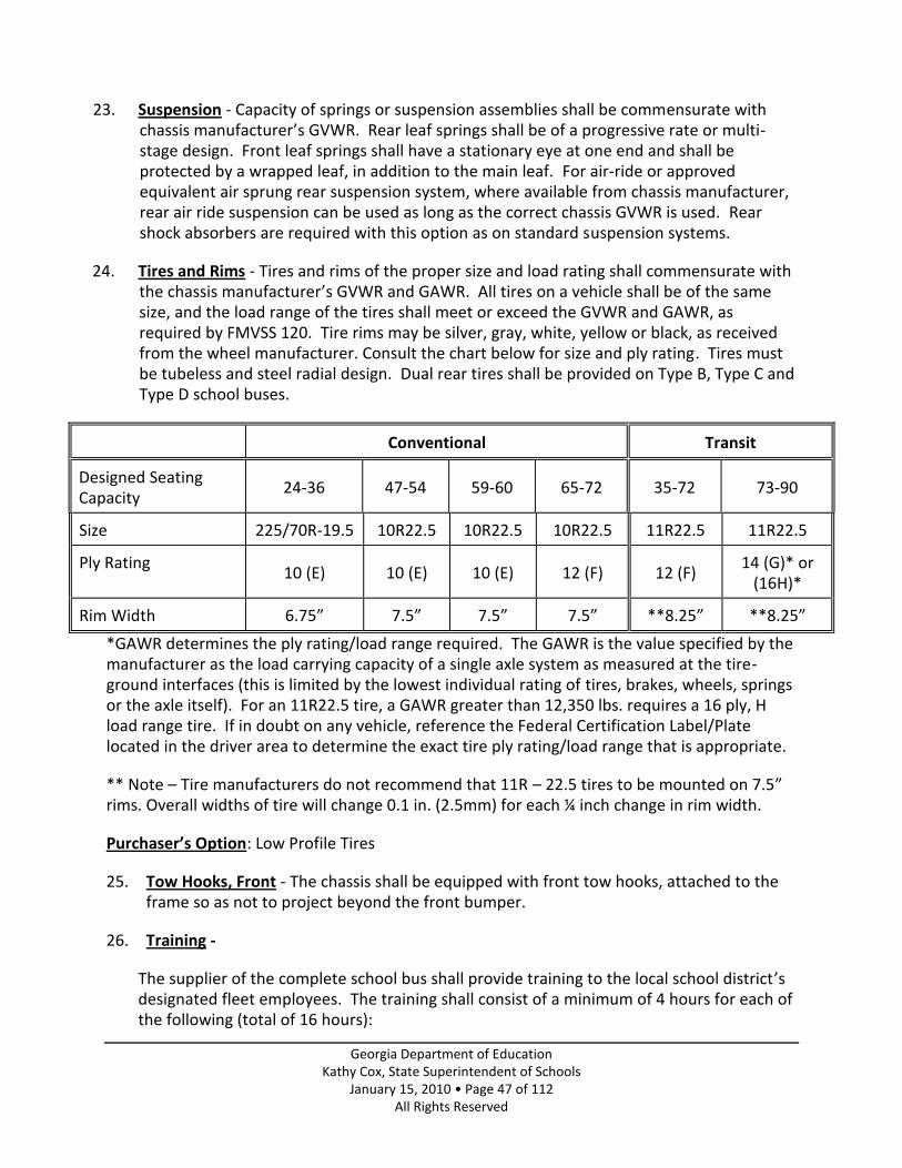
Georgia Department of Education Kathy Cox, State Superintendent of Schools
January 15, 2010 • Page 47 of 112 All Rights Reserved
23. Suspension - Capacity of springs or suspension assemblies shall be commensurate with chassis manufacturer’s GVWR. Rear leaf springs shall be of a progressive rate or multi-stage design. Front leaf springs shall have a stationary eye at one end and shall be protected by a wrapped leaf, in addition to the main leaf. For air-ride or approved equivalent air sprung rear suspension system, where available from chassis manufacturer, rear air ride suspension can be used as long as the correct chassis GVWR is used. Rear shock absorbers are required with this option as on standard suspension systems.
24. Tires and Rims - Tires and rims of the proper size and load rating shall commensurate with the chassis manufacturer’s GVWR and GAWR. All tires on a vehicle shall be of the same size, and the load range of the tires shall meet or exceed the GVWR and GAWR, as required by FMVSS 120. Tire rims may be silver, gray, white, yellow or black, as received from the wheel manufacturer. Consult the chart below for size and ply rating. Tires must be tubeless and steel radial design. Dual rear tires shall be provided on Type B, Type C and Type D school buses.
Conventional Transit
Designed Seating Capacity
24-36 47-54 59-60 65-72 35-72 73-90
Size 225/70R-19.5 10R22.5 10R22.5 10R22.5 11R22.5 11R22.5
Ply Rating 10 (E) 10 (E) 10 (E) 12 (F) 12 (F)
14 (G)* or (16H)*
Rim Width 6.75” 7.5” 7.5” 7.5” **8.25” **8.25”
*GAWR determines the ply rating/load range required. The GAWR is the value specified by the manufacturer as the load carrying capacity of a single axle system as measured at the tire-ground interfaces (this is limited by the lowest individual rating of tires, brakes, wheels, springs or the axle itself). For an 11R22.5 tire, a GAWR greater than 12,350 lbs. requires a 16 ply, H load range tire. If in doubt on any vehicle, reference the Federal Certification Label/Plate located in the driver area to determine the exact tire ply rating/load range that is appropriate.
** Note – Tire manufacturers do not recommend that 11R – 22.5 tires to be mounted on 7.5” rims. Overall widths of tire will change 0.1 in. (2.5mm) for each ¼ inch change in rim width.
Purchaser’s Option: Low Profile Tires
25. Tow Hooks, Front - The chassis shall be equipped with front tow hooks, attached to the frame so as not to project beyond the front bumper.
26. Training -
The supplier of the complete school bus shall provide training to the local school district’s designated fleet employees. The training shall consist of a minimum of 4 hours for each of the following (total of 16 hours):

Georgia Department of Education Kathy Cox, State Superintendent of Schools
January 15, 2010 • Page 48 of 112 All Rights Reserved
1) Engine maintenance/diagnostics 2) Transmission maintenance/diagnostics 3) Antilock brake maintenance/diagnostics 4) Body electrical/ multi-plex wiring
The training will be in addition to that provided at the State of Georgia School Bus Technicians’ Workshop. The training will be provided at the local school system’s fleet facility or at a regional location unless otherwise agreed upon by the local school district. Purchaser’s Option - Additional hours of training may be specified by the local system in
their bus bid proposal. Purchaser’s Option - A lap top computer with original (no copies will be accepted) software (engine, transmission diagnostics, etc.) with cables/ adapters needed to access the vehicle computer.
27. Transmission – Automatic - The automatic transmission on B series chassis shall be the
manufacturer’s standard supplied per GVWR of the chassis specification. The automatic transmission on type C and D model chassis shall have at least five forward gear ratios, with down shift inhibitors, plus integral torque converter which shall provide for an overall starting torque ratio in a forward range of at least 5.9:1. Converter shall be equipped with converter lockup. Transmission shall be electronically controlled and compatible to the required electronic engine. The transmission shift quadrant shall provide five forward drive ranges plus neutral and reverse ranges. Within the range selected, ratio changes shall be affected automatically and at full engine power, if desirable, and without use of an engine disconnect clutch. A transmission shift diagram shall be provided and mounted on the instrument panel or embossed on the handle of the gearshift lever. The neutral starting switch shall be designed and located so that the vehicle will not start in any position other than neutral. The automatic transmission system shall meet FMVSS 102.
Transmission Warranty on parts and labor will be 5 years, unlimited miles, 100 percent parts and labor. Warranty implementation will begin on date of delivery of the complete school bus.
Conventional Transit
Designed Seating Capacity
24-30 29-54 59-72 35-72 73-90
Automatic Transmission
C-1 1000 PTS*
2500 PTS 2500 PTS 2500 PTS 3000 PTS
* Test Transmission Alternative Fuel Test Transmissions: Blue Bird

Georgia Department of Education Kathy Cox, State Superintendent of Schools
January 15, 2010 • Page 49 of 112 All Rights Reserved
The Allison 2300 PTS transmission shall be a test transmission when utilized with the GM Vortec 8.1 propane fuel engine in conventional Type C buses. Thomas The Eaton Fuller Hybrid, EH-6E606B-P Medium-Duty Automated Manual, Transmission shall be a test transmission when utilized in 66-72 designed capacity Type C, hybrid drive train conventional buses. Purchaser’s Option: Allison Output Retarder - The Allison 3000 PTS Series Transmissions
may be equipped with an output retarder activated by the service brake pedal. Procedure for Automatic Transmission Acceptance into Georgia State Specifications
Transmissions must be tested prior to being accepted into the Georgia School Bus Specifications. Existing transmissions must be tested if any of the following apply:
1. There is less than 80% commonality of parts (not part number changes) between are designed transmission and its original design.
2. The transmission has been removed from the specifications for any reason.
The Pupil Transportation Division of the State Department of Education shall be notified by the transmission manufacturer/distributor whenever a transmission is being tested within the state or if a transmission is discontinued/no longer available for school buses in the state. The following test procedure will be used: The transmission is to be tested by a minimum of five (5) school systems within the state. The test sites must be diverse locations such as mountain, rural, metropolitan and coastal areas. The test will be conducted for at least eight (8) months prior to the Spring Meeting of the State Specification Committee. The committee shall be provided with letters of evaluation for the product tested. The committee reserves the right to require further testing of new or existing transmissions.
The Evaluation Transmission Certification form can be found on page 100 in the Georgia Bus Specification Manual.
Note: The testing process does not limit the number of transmissions that can be sold but requires the distributor to test a minimum of five (5) transmissions. It also requires the distributor to act in good faith by representing a transmission as a test/new design to potential customers. All transmissions must meet the minimum requirements listed in the state specifications. All transmissions that are being tested will only be approved in the vehicles tested per passenger capacity and chassis type.
28. Turn Signals Lights - Two front directional signals shall be provided and installed by the chassis manufacturer and shall be in compliance with FMVSS 108. These signals are to be operated by a steering post mounted, self-canceling directional signal switch with an illuminated “ON” indicator(s) in compliance with FMVSS 108. The chassis manufacturer

Georgia Department of Education Kathy Cox, State Superintendent of Schools
January 15, 2010 • Page 50 of 112 All Rights Reserved
will furnish a self-canceling directional signal switch. Fender-Mounted or Cowl Mounted directional signals are required.
Exception: On transit buses, Fender-Mounted directional signals do not apply.
The design of the turn signal system shall be such that the failure of any signal light to function will cause the illuminated indicator to indicate its malfunction. A variable load flasher that conforms to FMVSS 108 may be accepted in lieu of the illuminated indicator system. All lamps shall be post-grounded by use of ground wire or a strap running from the lamp socket to the bus body.
29. Undercoating - The chassis manufacturer shall coat the metallic portion underside of front fenders with rust-proofing compound for which compound manufacturers have notarized certification of compliance to chassis builder that compound meets or exceeds all performance and qualitative requirements of paragraph 3.4 of Federal Specifications TT-C-520b using modified test.
30. Warranty – Complete School Bus - See page 82 for specification on the complete school bus warranty.

Georgia Department of Education Kathy Cox, State Superintendent of Schools
January 15, 2010 • Page 51 of 112 All Rights Reserved
Part 4
Body Specifications
TYPES B, C AND D
Table of Contents PAGES
1. Back-Up Alarm ................................................................................................................ 54 2. Barriers ............................................................................................................................ 54 3. Battery Compartment ..................................................................................................... 54 4. Body Data Plate............................................................................................................... 54 5. Body Fluid Clean Up Kit ................................................................................................... 54 6. Bumper, Rear .................................................................................................................. 55 7. Bus Size ........................................................................................................................... 55 8. Child Check System – (not brand specific)...................................................................... 55 9. Color ............................................................................................................................. 55
Exterior Paint Painted Roof (Purchaser’s Option) Interior Paint Metal Treatment
Warranty – Exterior Paint 10. Communication ............................................................................................................... 57 11. Construction.................................................................................................................... 57
Body Mounting Colorado Racking Load Test Exterior Side Panel Floor Structure (Passenger Compartment) Fuel Filler Opening Door Insulation Interior Panels, Floor and Windows Openings Roof Roof Bows and Post Roof Stringer Rub Rails Screws, Bolts, Nuts and Washers Side Skirts Static Load Test Undercoating Wheel Housing Window Headers
12. Crossing Gate .................................................................................................................. 61 13. Disabled Vehicle Warning Devices ................................................................................. 62
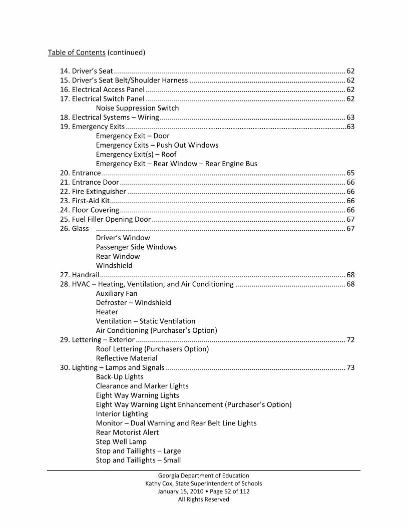
Georgia Department of Education Kathy Cox, State Superintendent of Schools
January 15, 2010 • Page 52 of 112 All Rights Reserved
Table of Contents (continued)
14. Driver’s Seat .................................................................................................................... 62 15. Driver’s Seat Belt/Shoulder Harness .............................................................................. 62 16. Electrical Access Panel .................................................................................................... 62 17. Electrical Switch Panel .................................................................................................... 62
Noise Suppression Switch 18. Electrical Systems – Wiring ............................................................................................. 63 19. Emergency Exits ......................................... ………………………………………………………………...63
Emergency Exit – Door Emergency Exits – Push Out Windows Emergency Exit(s) – Roof Emergency Exit – Rear Window – Rear Engine Bus
20. Entrance .......................................................................................................................... 65 21. Entrance Door ................................................................................................................. 66 22. Fire Extinguisher ............................................................................................................. 66 23. First-Aid Kit ...................................................................................................................... 66 24. Floor Covering ................................................................................................................. 66 25. Fuel Filler Opening Door ................................................................................................. 67 26. Glass ............................................................................................................................. 67
Driver’s Window Passenger Side Windows Rear Window Windshield
27. Handrail ........................................................................................................................... 68 28. HVAC – Heating, Ventilation, and Air Conditioning ....................................................... 68
Auxiliary Fan Defroster – Windshield Heater Ventilation – Static Ventilation Air Conditioning (Purchaser’s Option)
29. Lettering – Exterior ......................................................................................................... 72 Roof Lettering (Purchasers Option) Reflective Material
30. Lighting – Lamps and Signals .......................................................................................... 73 Back-Up Lights Clearance and Marker Lights Eight Way Warning Lights Eight Way Warning Light Enhancement (Purchaser’s Option) Interior Lighting Monitor – Dual Warning and Rear Belt Line Lights Rear Motorist Alert Step Well Lamp Stop and Taillights – Large Stop and Taillights – Small

Georgia Department of Education Kathy Cox, State Superintendent of Schools
January 15, 2010 • Page 53 of 112 All Rights Reserved
Table of Contents (continued) Strobe Light Turn Signal Lights
31. Manuals/Catalogs ........................................................................................................... 77 32. Mirrors ............................................................................................................................ 77
Cross View Mirror System Interior Mirror Rear Vision Mirror System
33. Pre-Delivery Service ........................................................................................................ 78 Delivery Inspection
34. Projections……… .............................................................................................................. 78 35. Reflectors. ....................................................................................................................... 78 36. Seatbelt Cutter ................................................................................................................ 79 37. Seating ............................................................................................................................ 79
Passenger Seats Passenger Seat Cushions Passenger Seat Frame and Mounting
38. Seating Capacity (definitions) ......................................................................................... 81 39. Steering Wheel ............................................................................................................... 81 40. Stop Arm ......................................................................................................................... 81 41. Sun Visor ......................................................................................................................... 81 42. Tail Pipe ........................................................................................................................... 81 43. Tow Hooks – Rear ........................................................................................................... 81 44. Training ........................................................................................................................... 81 45. Warranty – Complete School Bus ................................................................................... 82 46. Windshield Cleaning Steps ............................................................................................. 82 47. Windshield Wipers and Washers .................................................................................... 82

Georgia Department of Education Kathy Cox, State Superintendent of Schools
January 15, 2010 • Page 54 of 112 All Rights Reserved
NOTE: Where there is conflict between Georgia and Federal Motor Vehicle Safety Standards, Federal Specifications shall prevail. Buses must meet Georgia Specifications to the extent that National School Transportation Specifications and Procedures are exceeded or the item is specifically addressed; otherwise, 2005 National School Transportation Specifications and Procedures are considered as a minimum.
NOTE: Items listed as Purchaser’s Options must be specifically requested by the local school system.
1. Back-Up Alarm - An automatic, audible back-up alarm of at least 112 dBa or variable that can obtain 112 dBa meeting SAE J994b, shall be installed behind the rear axle.
2. Barriers - Barriers to meet FMVSS 222 must be furnished in front of forward facing seats, which do not have another seat within the distance specified by FMVSS 222. A barrier located at the step well shall have a kick/modesty panel installed between the bottom of the barrier and the floor and between the legs(s) and wall to ensure that pupils will not slip into the step well.
3. Battery Compartment - The body manufacturer shall securely mount the battery(ies) on a sliding tray in an enclosed, vented compartment in the side of the skirt of the body. The battery compartment door shall have a lock fastener operated by the same key as the Fuel Filler Door. Two keys shall be provided with each lock. Battery cables shall be long enough to allow the battery tray to be fully extended.
4. Body Data Plate – There shall be installed in each bus body, above the windshield or in the driver’s cabin area a permanently attached metal School Bus Manufacturer’s Body Data Plate(s) that is in a clearly visible location. Decals and glue are not acceptable. The Body Data Plate(s) information shall include (in part) a listing that the bus meets Georgia School Bus Specifications, the Build Date, the Body Number, the Designed Seating Capacity and the Equipped Seating Capacity of the school bus body (see definitions under “Seating Capacity”, page 81).
5. Body Fluid Clean-up Kit - Bus shall have a removable and moisture proof body fluid clean-up kit. It shall be properly mounted in full view and in accessible place in driver’s compartment and identified as a body fluid clean-up kit. The body fluid clean-up kit shall contain at least the following:
1-pair latex gloves 1-pick-up spatula 1-pkg. absorbent deodorant 1-wiping cloth 1-ready-to-use hospital grade disinfectant 1-individual portion of antiseptic hand rinse 1-contaminated materials bag and tie

Georgia Department of Education Kathy Cox, State Superintendent of Schools
January 15, 2010 • Page 55 of 112 All Rights Reserved
6. Bumper, Rear - The rear bumper shall be furnished and secured to the rear body frame by the body manufacturer and so designed to prevent hitching of rides thereon. The rear bumper shall be a one-piece bumper of pressed steel channel at least 3/16 inch by 9 1/2 inches and must be bolted to the chassis side frames and braced with material of equal impact ratio to that of the bumper. The bumper shall not be permanently attached to the body.
7. Bus Size - Overall length of the bus shall not exceed 45 feet, excluding accessories.
8. Child Check System – (not brand specific) - A child check system shall be provided meeting the following specifications:
The Child Check System shall activate: 1. When the eight way warning lights have been activated and fully cycled. 2. When the bus has been in continuous operation (ignition on, engine running) for 10
minutes. Once the Child Check System has been activated the following procedures must take place before the driver can exit the bus (open the entrance door) without the horns sounding until the system is deactivated. 1. The door must be closed before the ignition is turned off. 2. After the ignition is turned off, the driver must walk to the rear of the bus and
manually operate a deactivation switch. (When the deactivation switch is not controlled by the rear door handle, it shall be located above the rear door in the rear bulkhead and clearly labeled.)
3. Immediately upon deactivating, the interior dome light or such indicators shall activate to identify the system has disarmed.
4. The interior dome lights shall illuminate and remain on for a minimum of 60 seconds after deactivating.
5. Any attempt to exit the bus by opening the entrance door the horns will sound until system has been de-activated.
NOTE: In order to eliminate unnecessary idling, the driver must be able to unload students with the engine off and the key in the accessory or on/run position.
9. Color -
Exterior Paint - The exterior paint of the body shall be painted National School Bus Yellow, according to the specifications available from General Services Administration. The rear bumper and body side rails shall be in National School Bus Black in a manner approved by the Transportation Division, Georgia Department of Education. Tire rims may be silver, gray, white, yellow or black, as received from the wheel manufacturer.
School bus yellow paint shall meet SBMTC-008 for color and shall have a finished gloss rating of at least 85 at 60° and a distinctness of image rating of an average of at least 50 measured using the same method specified for gloss under “Paint Warranty”. Paint shall be applied for a total dry thickness of at least 1.8 mils over all painted surfaces.

Georgia Department of Education Kathy Cox, State Superintendent of Schools
January 15, 2010 • Page 56 of 112 All Rights Reserved
Purchaser’s Option: The roof of a school bus may be painted white; however, the front and rear roof caps must remain yellow. The white roof may not extend beyond the drip rail on the side.
Interior Paint - The interior of the body shall be painted with the body manufacturer’s standard color, unless otherwise specified in the bid.
Metal Treatment -
All metal except high-grade stainless steel or aluminum used in the construction of the bus body shall be zinc-coated or aluminum-coated or treated to prevent corrosion. This includes but is not limited to such items as structural members, inside and outside panels, door panels and floor sills. Excluded are such items as door handles, grab handles, interior decorative parts and other interior plated parts.
All metal parts that will be painted, in addition to the above requirements, shall be chemically cleaned, etched, zinc phosphate-coated and zinc chromate or epoxy-primed to improve paint adhesion.
In providing for these requirements, particular attention shall be given to lapped surfaces, welded connections of structural members, cut edges on punched or drilled hole areas in sheet metal, closed or box sections, un-vented or un-drained areas and surfaces subjected to abrasion during vehicle operation.
As evidence that the above requirements have been met, samples of materials and sections used in the construction of the bus body shall not lose more than 10 percent of material by weight when subjected to a 1,000-hour salt spray test, as provided for in the latest revision of ASTM Standard B-117.
Warranty – Exterior Paint - Paint finish coats to chassis hood, fenders, and cowl shall be warranted for 60 months unlimited mileage, 100 percent parts and labor, for adhesion, color retention, and gloss retention. Acceptable lower limits during the warranty period are as follows: Adhesion: During the 60-month warranty period, paint and priming compounds shall not fail to adhere to the bus with normal use and care. Color Retention: During the first 36 months from the in-service date, the color coat shall not shift colors more than 4 ΔE from the centroid as specified in School Bus Manufacturers Technical Council Publication SBMTC-008. During the 60-month warranty period, the color coat shall not shift color more than 8 ΔE from the centroid as specified in SBMTC-008.

Georgia Department of Education Kathy Cox, State Superintendent of Schools
January 15, 2010 • Page 57 of 112 All Rights Reserved
Gloss: During the first 36 months from the in-service date, the gloss reading shall not fall below 60 at 60°. During the 60-month warranty period, the gloss reading shall not drop below 30 at 60°. All measurements shall be the average of 12 readings taken at various points on the bus, but no reading shall be more than 3 points under the stated minimum. All readings shall be taken after the bus is thoroughly washed to remove road film and dust.
10. Communication -
Code 40-6-161 “It shall be unlawful to operate any school bus which is transporting students unless the driver of the bus is equipped with one or more devices to allow live communication between the driver and school officials or public safety officials or both. Such communication may be provided by two-way radio, cellular telephone, or any device which provides similar communications capability.”
If two-way radios are utilized on school buses, the following specifications are recommended by the National School Transportation Specifications and Procedures for proper installation:
The radio mounting shall be in the driver’s compartment in a safe, secure location, so as not to interfere with normal bus operations. Mounting shall be permanent. Temporary mountings are not acceptable. Wiring for the radio shall be protected by a fuse or circuit breaker and permanently connected to an accessory circuit shut off by the ignition switch. The antenna shall be permanently mounted to the cowl or roof so as not to interfere with the driver’s vision of the roadway. Antenna lead-in cable shall be permanently secured with the proper clamps, grommets and sealant. Antenna cable may not pass through the window opening.
11. Construction -
The body shall consist of the floor system, bows, posts, bow frames, strainers, front and rear framing, sheet metal exterior skin, wheel housings, and rub rails. The exterior roof caps, service access panels, and light panels shall be of steel except that fiber glass or other composite materials may be used if all Federal Motor Vehicle Safety Standards are met and if the manufacturer can show that the material used is durable under normal operating conditions. All openings between chassis and passenger carrying compartment made due to alteration by body manufacturer must be sealed.
The body assembly shall be designed to withstand vibrations transmitted through the chassis. The windshield or corner post should be of sturdy construction having a minimum thickness equal to U.S. Standard gauge number 14, and shall be designed so as not to obstruct the driver’s vision.

Georgia Department of Education Kathy Cox, State Superintendent of Schools
January 15, 2010 • Page 58 of 112 All Rights Reserved
Body Mounting - The body shall be attached to the chassis frame by means of the manufacturer’s regular clips. Shear bolts or other equally effective device may be used to prevent slippage. Anti-squeak material or rubber pads shall be used to insulate the body from the chassis.
Colorado Racking Load Test - All bus manufacturers shall certify that the bus body construction meets or exceeds all testing standards of the Colorado Racking Load Test. This certification is to assure adequate shear stiffness and construction strength of the bus body. Certification shall be noted on the permanently attached metal “Body Data Plate”(s). Decals and glue are not acceptable.
Exterior Side Panel - Exterior side panels shall have a minimum thickness of not less than 20-gauge sheet steel (or an equivalent material), free of scale and buckles. Exterior side panels shall be fastened to roof bows or body posts by means of rivets, bolts or self-locking, Phillips serrated head designed sheet metal screws. Spot welding of side panels will not be acceptable. Panels shall extend below the floor line to form a skirt of pleasing dimensions and appearance. The skirt shall be adequately supported and braced to the under body structure. The side panels shall be cut away at the wheel housings to permit easy rear wheel removal and shall be suitably reinforced at this point. Any design of exterior panel must meet FMVSS 220 and FMVSS 221.
Floor Structure (Passenger Compartment) - The floor panel/sheeting shall be not less than 14-gauge steel. All floor panel/sheeting joints shall be gas tight to prevent the entrance of engine exhaust gases. In no case shall the distance between the floor supporting cross members be greater than eleven inches. A sectional type floor design with flanged edges of adjacent sections bolted, welded, bonded or riveted together to form a cross member will be acceptable. All cross members shall be equal in length, except where structural members of features restrict the area. All cross members shall bear upon the chassis frame channels. All cross members shall have a minimum thickness equal to U.S. Standard 14-gauge, or the main supporting cross members shall have a minimum thickness equal to U.S. Standard 10-gauge and the intermittent cross members shall have a minimum thickness equal to U.S. Standard gauge 16.
The connections between the roof bows and/or side posts and cross members shall be capable of distributing the load from the vertical posts to all floor cross members. Body structure shall meet requirements of FMVSS 220/221/222/404.
On Type B vehicles, the floor shall be level except for wheel housing, toe board, and operator’s platform area.
Exception: Cross members are not required to extend the full width of the body in the wheelhouse area and the fuel filler area where structural members interfere. However, if cross members do not run the full width of the body, in these areas, they shall be connected to the adjacent cross member or shall sit on the chassis frame channels. Deviation of manufacturer design and spacing of cross members in these areas shall be allowed, but shall be designed and constructed to support all fixed and dynamic loads

Georgia Department of Education Kathy Cox, State Superintendent of Schools
January 15, 2010 • Page 59 of 112 All Rights Reserved
without deformation of the under body structure, strains to body, or fractures of member joints. Note - The wording found in this section, “Floor Structure”, of the 2008 Georgia School Bus Specifications Manual will hereby supersede the wording on “Floor Structure” in previous Georgia Specifications. The new wording above will take precedence over the previous wording adopted.
Fuel Filler Opening Door - A suitable door of 16-gauge steel having a lock fastener shall be installed over fuel filler opening on side of body. Two keys shall be provided with each lock.
Exception: Type B vehicles - Manufacturer’s Standard
Insulation - The body panels (side, roof, front, and rear including corners) and roof bows shall be insulated completely with not less than l l/2 inches of fiberglass insulation material which is fire and moisture resistant, or approved equal. Insulation material shall be approved by Underwriters Laboratories, Inc.
The entire underside of the body, including wheel housings, shall be coated to a minimum thickness of 1/16” with high quality automotive type underseal, Federal Specification 11-C-520b or approved equal, to protect the body from rust and to seal and insulate the floor.
Interior Panels, Floor and Windows - The body shall be of double wall construction throughout except for floor and windows. The interior panels shall be not less than 22-gauge sheet steel securely fastened to frame members in an approved manner.
Panels shall be so designed and fastened to minimize vibrations and rumble and shall be installed so as to be easily removed. There shall be a cove molding installed at the junction of the side paneling and the floor. A suitable metal strip or molding shall be directly below the side windows or an approved equally effective design. If the ceiling is constructed so as to contain lapped joints, forward panels shall be lapped by rear panels and exposed edges shall be beaded, hemmed, flanged, or otherwise treated to minimize sharp edges.
Openings - The Repair and Access Openings shall be provided for servicing, removing or repairing any chassis components, such as the transmission, engine, etc., which must be reached through the floor or firewall.
The floor and floor covering materials shall have an opening cut over the fuel tank in the area of the fuel sending unit and/or in-tank fuel pump, allowing the removal of the fuel sending unit and/or fuel pump. This opening shall be sealed and covered by a metal plate attached to the flooring with metal screws.
Roof - The roof shall be made of not less than 20-gauge sheet steel panels formed to fit the roof of the bus. All joints shall be adequately sealed to render them completely watertight.

Georgia Department of Education Kathy Cox, State Superintendent of Schools
January 15, 2010 • Page 60 of 112 All Rights Reserved
Roof Bows and Post - Roof bows and body post may be one-piece or three-piece construction. When roof bows and post are separated and jointed at the window header, the connections shall be such as to develop the full strength of the cross section.
Bows and post shall have a minimum thickness equal to U.S. Standard 16 gauge and shall have a minimum depth of 1 l/4 inches. Bows or posts shall be securely anchored to the floor structure, except at the wheelhouse. A roof bow and post design, which meets FMVSS 220 and FMVSS 221, and passes the side intrusion test, will be acceptable.
Roof Stringer - Two or more roof stringers or longitudinal members shall be provided to connect the roof bows and to reinforce the flattest portion of the roof skin. These members shall be a minimum thickness equal to U.S. Standard 16-gauge metal 3 inches wide before forming. These stringers may be installed between roof bows or applied externally.
The roof stringers shall extend from the windshield header and when combined with the rear emergency doorpost are to function as longitudinal members extending from the windshield header to the rear floor body cross member. At all points of contact between stringers or longitudinal members and other structural material, attachment shall be made by means of welding, riveting or bolting. The design and application of roof stringers must meet FMVSS 220 and FMVSS 221.
Rub Rails – Externally applied rub rails shall be installed on each side of the bus body. The minimum thickness shall be U.S. Standard gauge 16. These rails shall be corrugated or profiled to provide maximum strength.
(1) One rub rail shall be located under the windowsills. It shall begin at the entrance doorpost and extend to the rear body post on the right side of the bus body, and shall begin at the windshield post and extend to the rear body post on the left side of the bus body. The above rub rail may be omitted only when the internal longitudinal member below the window meets or exceeds the requirement of the rub rail. (2) The seat level rub rail shall begin at the entrance doorpost on the right side of the body and except for the emergency door, extend around the rear of the body to the left windshield post. (3) The floor level rub rail shall begin at the entrance doorpost on the right side of the bus body and extend to the rear body post, and shall begin at the left windshield post and extend to the rear body post on the left side of the bus body except for the openings at the wheel wells. (4) A rub rail at the bottom of the skirt shall begin at the entrance doorpost and extend to the left windshield post with the exception of the openings at the wheel wells and the bumper.
Rub rails shall be securely attached at least twice to each body post within their length. Splices are not allowed unless rub rail is extended around rear corner radius and must be made at a body post near the rear of body. No exception other than is caused by location of battery box door, engine doors, side emergency door, and electrical panel access door.

Georgia Department of Education Kathy Cox, State Superintendent of Schools
January 15, 2010 • Page 61 of 112 All Rights Reserved
NOTE – Power lift doors shall have rub rails
Screws, Bolts, Nuts, and Washers – All screws within reach of children shall be Phillips head, or torx bit type. All bolts, nuts, screws, and washers used in the construction of the body shall be Parkerized, cadmium plated, or thoroughly treated to prevent rust.
Side Skirts – School bus body side skirts shall be the manufacturer’s standard length.
Static Load Test – Body structure shall meet requirements of FMVSS 220.
Undercoating - The entire underside of the body, including wheel housings, shall be coated to a minimum thickness of 1/16” with high quality automotive type underseal, Federal Specification TT-C-520b or approved equal, to protect the body from rust and to seal and insulate the floor. Not required on heat shields placed between exhaust system and body, which are provided to reduce the temperature on chassis manufacturer’s floor.
Wheel Housing - Wheel housings shall be the full open type to provide maximum access to tires and wheels. Their thickness shall be of not less than 18-gauge steel and shall be securely attached to floor sheets to prevent any water or dust from entering the body.
The height of the wheel housings shall not be greater than the distance from the floor to the underside of the seats. The size of the wheelhouse shall be such that tire chains will have proper clearance.
Window Headers - An internal window header shall be located at the roofline. It shall be securely fastened to all roof bows or body posts.
An additional internal longitudinal structural member shall be located between the window and floor lines.
The fastening method employed shall be such that the strength of the members is fully utilized. A window header design, which meets or exceeds FMVSS 220 and FMVSS 221 and passes the side intrusion, is acceptable.
12. Crossing Gate - Buses shall be equipped with a crossing gate. The gate, when activated, shall extend a minimum of 5’6” from the face of the front bumper. The gate shall be on the right side of the front bumper and shall be activated by the same switch controlling the stop arm and work in conjunction with the stop arm. The crossing gate shall be electrically operated.
Purchaser’s Option: Air-operated crossing gate may be requested; chassis must be equipped or bid with the power source.
When both the stop arm and the crossing gate are air operated each device shall be equipped with a separate solenoid and pressure regulator.

Georgia Department of Education Kathy Cox, State Superintendent of Schools
January 15, 2010 • Page 62 of 112 All Rights Reserved
13. Disabled Vehicle Warning Devices - School bus shall come equipped with disabled vehicle hazard warning devices that meet FMVSS 125 to be displaced according to state law in event of a prolonged stop on street or highway. Reflectors to be fitted in a case and conveniently mounted in the driver’s compartment area.
14. Driver’s Seat - The driver’s seat shall be of the high back type with a minimum seat back adjustment of 15 degrees and with a head restraint to accommodate a 5th percentile female to a 95 percentile adult male as defined in FMVSS 208. The driver’s seat shall be secured with nuts, bolts, and washers or flange-headed nuts. The covering shall be cloth or a combination cloth and vinyl. Seat shall have a minimum 4-inch adjustment front to rear, and a minimum 4-inch adjustment up and down. Front to rear adjustment shall be designed for fingertip control without use of tools.
15. Driver’s Seat Belt/Shoulder Harness - A type 2 lap belt/shoulder harness seat belt shall be provided for the driver. On buses where the driver’s seat and upper anchorage for the shoulder belt are both attached to the body structure, a driver’s seat with an integrated Type 2 -lap/shoulder belt may be substituted. On buses where the driver’s seat and upper anchorage for the shoulder belt are separately attached to both body and chassis structures (i.e., one attached to the chassis and the other attached to the body), a driver’s seat with integrated Type 2 lap/shoulder belt should be used. The assembly shall be equipped with an emergency locking retractor (ELR) for the continuous belt system. The lap/shoulder belt shall be designed to allow for easy adjustment in order to fit properly and effectively protect drivers varying in size from 5th percentile adult female to 95th percentile adult male.
The driver’s seat belt shall be made in a high visibility color such as orange or lime green on Type B, C and D buses.
16. Electrical Access Panel - There shall be installed accessible to the driver a enclosed electrical accessory panel(s) in which shall house serviceable fuses, circuit breakers, relays, flashers, buzzers, accessory junction blocks and other such components. The panel shall be enclosed in an adequate manner which shall protect such components from the elements and have a securely mounted but easily removable service access cover. Exterior panels shall be located under the driver’s side window area and shall have a lockable steel door. The panel shall be clearly labeled as “Electrical Access Panel”.
Buses with more than one electrical panel shall have all panels clearly labeled as “Electrical Access Panel” in each location.
Buses with multiplex wiring shall have termination/control panels clearly identified in all locations.
17. Electrical Switch Panel -

Georgia Department of Education Kathy Cox, State Superintendent of Schools
January 15, 2010 • Page 63 of 112 All Rights Reserved
All switches, indicators and controls shall be located in a driver oriented ergonomic location. Indicator lights shall be located in positions which require minimal visual distraction to view.
Noise Suppression Switch – There shall be a manual noise suppression switch installed in the electrical switch panel. The switch shall be labeled and alternately colored. This switch shall be an on/off type that deactivates body equipment that produces noise, including, at least, the am/fm radio, heaters, air conditioners, fans and defrosters. This switch shall not deactivate safety systems, such as windshield wipers, lighting systems or Child Check Systems. Once the switch has been reactivated, all electronic controls shall return to their original operations without driver reset.
18. Electrical Systems – Wiring - All wiring shall conform to standards of the Society of Automotive Engineers, shall be color and number coded, insulated and protected by plastic loom covering or fibrous loom protection. All joints shall be soldered or joined by equally effective connectors. Circuits shall be arranged as follows:
a. Clearance and step well lamps b. Dome lamps c. Ignition and emergency door signal d. Turn signals e. Stop arm and alternately flashing signal lamps f. Heater g. All body electrical circuits, with the exception of hazard-warning lights, shall be
operated through a solenoid actuated through the ignition switch.
Wiring through drilled holes in body shall be grommet protected. Wiring extending over sharp edges shall be protected by adequate loom covering.
19. Emergency Exits -
Emergency Exit - Door - A suitable all- metal emergency door shall be provided at the rear center of the body or in case of rear engine buses, located on the left side of the body with a minimum twelve-inch clear aisle on rear engine buses. The door shall provide an emergency exit conforming to the requirements of FMVSS 217. The bottom of the opening provided shall not be above the floor line of the body interior. The door shall be securely hinged with one piano type or two heavy-duty pin-type hinges and shall open outward. Piano type hinges shall be equipped with a brass or stainless steel rod. The emergency door shall be designed to open from the inside and outside of the bus and shall be equipped with a fastening device, which may be quickly released, but is designed to offer protection against accidental release. Control from the driver’s seat shall not be permitted. Provisions for opening from the outside shall consist of a non-detachable device designed to prevent hitching-to, but to permit opening when necessary.
The emergency door shall be equipped with a slide-bar cam-operated lock. The slide bar shall have a minimum stroke of one inch. The emergency lock shall be equipped with a

Georgia Department of Education Kathy Cox, State Superintendent of Schools
January 15, 2010 • Page 64 of 112 All Rights Reserved
suitable electric plunger-type switch and two buzzers, one located in the driver’s compartment and one located near the emergency door that meet FMVSS 217. The switch shall be enclosed and the wires leading from the switch shall be concealed in the body. The switch shall be installed so that the plunger of the switch contacts the farthest edge of the slide bar in such a manner that a slight movement of the slide bar will immediately close the circuit on the switch and activate the buzzer.
The door lock shall be equipped with an interior handle that extends approximately to the center of the emergency door. It shall lift up to release the lock.
The rear emergency door shall have a holding device to maintain the emergency door open to a minimum of 90 degrees. The device shall not require any action on the part of the user beyond moving the door to the minimum holding position. The device shall require a positive manual effort to allow closure. Positive manual effort shall be defined as: Performing the prescribed manufacturer’s procedures to allow closure. The device shall be so designed as not to allow closure through incidental contact when exiting the bus or coming in contact with the door. The device shall permit the user to close the door from inside or outside the bus body.
A large laminated or tempered safety glass panel shall be provided in the upper and lower part of the door, the exposed size of the upper glass being not less than 400 square inches, the bottom not less than 350 square inches. The glass shall be securely mounted in a fully watertight manner. The entire rear door shall be properly contoured and weather-stripped to provide a rain-tight fit with the bus body. No steps are to be provided for the emergency door.
Inside of door header shall be padded with an energy-absorbing material a minimum of 3 inches wide.
If a side emergency door is necessary to meet the minimum square inches required for emergency exits, it must meet FMVSS 217. A flip seat is permissible at the side emergency door.
Emergency Exits - Push-Out Windows - Each side of the body shall be equipped with horizontal or vertical full-hinged push-out type split-sash window(s). Vertical hinged push-out windows must open toward the front of the bus body. Emergency push-out windows must be in the following capacity vehicles:
Designed Seating Capacity Number of Windows Per Side 0-48 1
49-78 2 79-90 3
Emergency push-out windows shall have a positive latch and shall be so constructed and equipped as to actuate an audible signal when latch is moved. Words “EMERGENCY EXIT”
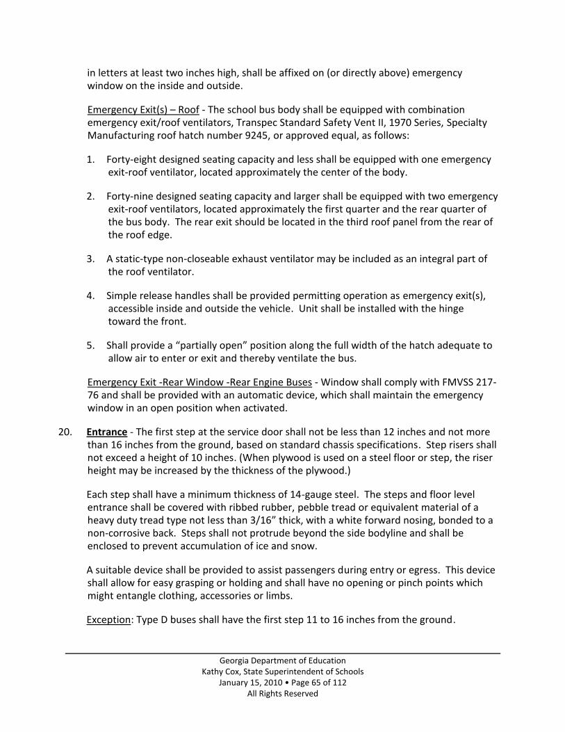
Georgia Department of Education Kathy Cox, State Superintendent of Schools
January 15, 2010 • Page 65 of 112 All Rights Reserved
in letters at least two inches high, shall be affixed on (or directly above) emergency window on the inside and outside.
Emergency Exit(s) – Roof - The school bus body shall be equipped with combination emergency exit/roof ventilators, Transpec Standard Safety Vent II, 1970 Series, Specialty Manufacturing roof hatch number 9245, or approved equal, as follows:
1. Forty-eight designed seating capacity and less shall be equipped with one emergency exit-roof ventilator, located approximately the center of the body.
2. Forty-nine designed seating capacity and larger shall be equipped with two emergency exit-roof ventilators, located approximately the first quarter and the rear quarter of the bus body. The rear exit should be located in the third roof panel from the rear of the roof edge.
3. A static-type non-closeable exhaust ventilator may be included as an integral part of the roof ventilator.
4. Simple release handles shall be provided permitting operation as emergency exit(s), accessible inside and outside the vehicle. Unit shall be installed with the hinge toward the front.
5. Shall provide a “partially open” position along the full width of the hatch adequate to allow air to enter or exit and thereby ventilate the bus.
Emergency Exit -Rear Window -Rear Engine Buses - Window shall comply with FMVSS 217-76 and shall be provided with an automatic device, which shall maintain the emergency window in an open position when activated.
20. Entrance - The first step at the service door shall not be less than 12 inches and not more than 16 inches from the ground, based on standard chassis specifications. Step risers shall not exceed a height of 10 inches. (When plywood is used on a steel floor or step, the riser height may be increased by the thickness of the plywood.)
Each step shall have a minimum thickness of 14-gauge steel. The steps and floor level entrance shall be covered with ribbed rubber, pebble tread or equivalent material of a heavy duty tread type not less than 3/16” thick, with a white forward nosing, bonded to a non-corrosive back. Steps shall not protrude beyond the side bodyline and shall be enclosed to prevent accumulation of ice and snow.
A suitable device shall be provided to assist passengers during entry or egress. This device shall allow for easy grasping or holding and shall have no opening or pinch points which might entangle clothing, accessories or limbs.
Exception: Type D buses shall have the first step 11 to 16 inches from the ground.

Georgia Department of Education Kathy Cox, State Superintendent of Schools
January 15, 2010 • Page 66 of 112 All Rights Reserved
21. Entrance Door - The entrance door shall be a double wall steel or aluminum, outward opening or jackknife (forward folding), located at the right front corner of the body and controlled by the driver through a manual or power device of approved construction. The door shall be adequately supported on piano-type or pivot-type hinges, and shall be provided with suitable weather stripping. The manual door control linkage shall be of such design as to prevent inadvertent opening, including a manual over- center locking feature, plus a manual locking catch.
If the door is a split-type design, a safety gap of approximately two inches shall be allowed between the two halves of the door, and this opening shall be filled by means of suitable flexible safety flaps securely attached to the door. The door shall completely enclose the step well and when fully opened shall provide an entrance of not less than 24 inches. The door shall be so designed and the weather stripping so mounted that there is no tendency for the stripping to dislodge during opening and closing operations. Two glassed-in openings shall be provided in each door half with panes securely mounted in a fully water tight manner. A suitable drip molding or rail to shed water out of the door area shall be provided.
Inside of door header shall be padded with a pad of at least 3 inches wide and 1 inch thick and extend the full width of the door.
22. Fire Extinguisher - One pressurized, rechargeable, dry chemical type, 5 lbs. fire extinguisher complete with hose, approved by Underwriters Laboratories, Inc., with a total rating of 2-A:10BC or greater. Extinguisher must be mounted in a bracket located in the driver’s compartment and readily accessible to the driver and passengers. A pressure gauge shall be mounted on the extinguisher so as to be easily read without moving the extinguisher from the mounted position.
23. First-Aid Kit - Bus shall have Grade A metal first-aid kit, mounted in full view and in accessible place in driver’s compartment. The number of units and contents shall be as designated.
4-inch bandage compress 2 pkgs. 2-inch bandage compress 1 pkg. 1-inch adhesive compress 2 pkgs. 40-inch triangular bandage with two safety pins 2 pkgs. Eye dressing packet 1 pkg. 24 x 72-inch gauge compress 1 pkg. 1-pair latex gloves 1 pkg. 1 mouth-to-mouth airway 1 pkg.
24. Floor Covering - The floor in the underseat area, including the wheel housings and driver’s compartment and toe board, shall be covered with fire resistant rubber or equivalent floor covering. This material shall have a minimum thickness of .125 inch. The wheel housing covering shall be seamless, molded, and one-piece.

Georgia Department of Education Kathy Cox, State Superintendent of Schools
January 15, 2010 • Page 67 of 112 All Rights Reserved
The composition of the floor covering to be used under the seats, wheel housings, and driver’s compartment shall be of the same composition as the floor covering used in the aisle of the bus.
Floor covering in the aisle shall be non-skid, wear-resistant type. The overall minimum thickness shall be .1875 inch. Ribbed type material may be used.
Floor covering must be permanently bonded to the floor and must not crack when subjected to sudden changes in temperature. Bonding or adhesive material shall be waterproof and shall be of type recommended by manufacturer of floor covering material. All seams shall be sealed with waterproof sealer and covered with a protective molding, chemically bonded or heat welded.
The floor and floor covering materials shall have an opening cut over the fuel tank in the area of the fuel sending unit and/or in-tank fuel pump, allowing the removal of the fuel sending unit and/or fuel pump. This opening shall be sealed and covered by a metal plate attached to the flooring with metal screws.
25. Fuel Filler Opening Door - A suitable door of 16-gauge steel having a lock fastener shall be installed over fuel filler opening on side of body. Two keys shall be provided with each lock.
Exception: Type B vehicles - Manufacturer’s Standard
26. Glass - All glass shall meet FMVSS 205 and FMVSS 217.
Driver’s Window - The driver’s window shall be a two-piece vertical sliding-sash type window.
Passenger Side Windows - The side windows shall be split-sash type. The windows and frames shall be designed and constructed to guarantee a rain-tight, weather-tight dry body well. A suitable drip rail, visor or similar water shedding device shall be provided for each window. The last window on each side may be set in a waterproof manner, without provision for adjustment, if the body design makes it impracticable to install an adjustable window at that point. Minimum window width shall be 22 inches. The amount of window travel shall be not less than 9 inches or more than 12 inches. The top sash shall be controlled by a latch with no exterior protrusion.
Rear Window - A rear window shall be installed on each side of the rear emergency door. Each rear window shall have a minimum glass area of 140 square inches and shall be set solid in a waterproof manner.
Exception: Rear Engine Transit Buses
A large laminated or tempered safety glass panel shall be provided in the upper and lower part of the emergency door, the exposed size of the glass being not less than 400 square inches, the bottom not less than 350 square inches. The glass shall be securely mounted in a fully watertight manner.

Georgia Department of Education Kathy Cox, State Superintendent of Schools
January 15, 2010 • Page 68 of 112 All Rights Reserved
Windshield - Glass in windshield shall be heat-absorbent, laminated plate. Windshield shall be large enough to permit driver to see roadway clearly, shall be slanted to reduce glare, and shall be installed between front corner posts that are designed and placed to afford minimum obstruction to driver’s view of roadway.
Windshield shall be tinted and have horizontal gradient band starting slightly above line of driver’s vision and gradually decreasing in light transmission to 20 percent or less at top of windshield.
27. Handrail - Handrails and mounting shall be designed to minimize the possibility of student’s clothing or personal items from becoming lodged or caught while exiting the bus as evidenced by the passing of the NHTSA string and nut test. Purchaser’s Option: School districts may wish to add an additional handrail in the entrance area of the bus body to assist students with disabilities in gaining better access and ability to enter and exit the bus.
28. HVAC – Heating, Ventilation, and Air Conditioning -
Auxiliary Fan – The bus body shall be equipped with a minimum of one auxiliary fan that shall meet the following requirements:
a. A fan for the left and/or right sides of the windshield shall be placed in a location where they can be adjusted for maximum effectiveness and where they do not obstruct vision to any mirror.
b. Fans shall have 6-inch (nominal) diameter; and
c. Fan Blades shall be enclosed in a protective cage. Each fan shall be controlled by a separate switch.
Defroster – Windshield
The body shall be so equipped as to provide ducted, forced warm air to both right and left sides of the windshield, the window to the left of the driver and the glass on the entrance door and step well area directly to the right of the driver. The total air volume moved shall be adequate to keep both right and left windshield free of frost or condensation. Defrosting may be accomplished by the left side heater, right side heater or both.
Heater
A heavy-duty combination fresh air and re-circulating air heater shall be provided. A duct shall be provided along the left side of the body extending beyond the driver’s compartment to provide heated air toward the rear of the bus body.
The heating system shall be so designed as to enable the driver to regulate the heated airflow in the driver’s compartment. If the fresh air intake is located on the side of the bus below the driver’s window, there shall be a sheet steel air scoop of approved design

Georgia Department of Education Kathy Cox, State Superintendent of Schools
January 15, 2010 • Page 69 of 112 All Rights Reserved
mounted in such a manner as to provide a slight pressurized air supply into the heater when the bus is in motion. The air scoop shall be made of not less than 20-gauge steel and shall be securely fastened to the body panel with sheet metal screws. The heater shall be located at the driver’s left and shall rest upon the floor of the body and against the body wall.
A right side or step well heater shall be provided. The heater shall have electric motor driven fan or fans. Defrosting of the entrance door is required and right windshield is preferred.
Heavy-duty tube and aluminum fin type brass or copper cores shall be furnished. The heater cores shall be set in rubber or shall be otherwise suitably supported in a manner to minimize shocks and strains, which might produce core leaks. Hose connections to core inlet and outlet shall be suitably supported to prevent vibrations being transferred to the core and causing leaks. All switches for the control of the heater fan motors shall be grouped with motor protection fuses or circuit breakers in a manner to provide maximum accessibility. A suitable water flow or air flow control shall be provided on the heater within easy reach of the driver. Heater hoses inside the bus body shall be covered or shielded. All hoses shall be continuous between the engine and the heater/defroster cores. Connections shall be made in such a manner as to prevent separation. Each heater water circuit installation shall include a brass ¾ inch gate valve or quarter turn ball seat valve installed as near the engine as possible in both the supply and return lines. Accessible bleeder valves shall be installed in an appropriate place in the return lines of Body Company installed heaters to remove air from the heater lines.
The heater hoses should be as short as possible but must not interfere with normal engine maintenance practices. The hose shall not rub against sharp edges nor interfere with or restrict the operation of the engine functions. Heater lines on the interior of the bus shall be shielded to prevent scalding of the driver or passengers.
Exception: A rear under seat heater of not less than 80,000 B.T.U. and a heat booster pump are required on 73 designed capacity and larger buses.
Heater Performance –
The school bus heating system shall provide evenly distributed heat throughout the school bus body and provide defrosting for the entire windshield surface and the entrance door. All school bus suppliers are expected to meet the following heater/defroster performance specifications. A letter from the school bus supplier must be provided to the GaDOE annually for buses bid under newly adopted specifications. The letter is for certifying that their heater/defroster system meets or exceeds the following performance guidelines:
a. A temperature measurement that is taken thirty-nine (39) inches inward from side walls, thirty-nine (39) inches inward from windshield and rear door, and thirty-six (36) inches above the floor. It shall include measurements from the front, middle and rear of the bus. The heat shall be evenly distributed through the aisle area.
b. The bus will be soaked at an ambient temperature of zero (0) degrees Fahrenheit for fifteen (15) hours. The temperature must rise to 50 degrees Fahrenheit inside in twenty

Georgia Department of Education Kathy Cox, State Superintendent of Schools
January 15, 2010 • Page 70 of 112 All Rights Reserved
(20) minutes when one hundred and seventy (170) degree water is applied at a rate of three (3) gallons per minute at a maximum of six (6) PSI pressure.
c. Maximum current flow for heater and defrosters shall not exceed forty-five (45) amperes
d. Heater cores installed in school buses sold in the State of Georgia shall meet the following test standard:
Static Pressure Test – 150 PSI Cycle Test – 20-50 PSI Hydraulic surge pressure, 450,000 cycles minimum
Core Flow Restriction - Total heater system flow restriction shall be measured at a flow rate of three (3) gallons per minute at a maximum of six (6) PSI pressure when measuring heater performance.
Defroster Performance -
Defrosters shall be included in the total electrical load for heaters and meet the following criteria:
a. Capable of defrosting the total windshield area in a reasonable period of time under all normal driving conditions
b. Shall provide means of defrosting entrance door glass independent of the windshield c. Capable of mixing a minimum fifty (50) percent outside fresh air with defrosting air d. System shall exceed the SAE standard J381-J382 performance requirement without the
use of an auxiliary fan and with three (3) gallons per minute one hundred seventy (170) degree water applied
Ventilation – Static Ventilation
The body shall be equipped with a ventilation system suitably controlled of sufficient capacity to maintain proper quantity of air without opening windows except in extremely warm weather. A static type exhaust roof ventilator shall be installed in low-pressure area of roof panel. The ventilator shall be designed to provide full protection from rain and to exhaust air from within the bus body by creating a low-pressure area while the bus is in motion. A roof hatch with a non-closeable ventilator may be used in place of body manufacturer’s designed static ventilator, provided installation is in low pressure area of roof.
Air Conditioning (Purchaser’s Option)
The following specifications are applicable to all types of school buses that may be equipped with air conditioning. This section is divided into two parts. Part 1 covers performance specifications and Part 2 covers other requirements applicable to all buses. 1. Performance Specifications

Georgia Department of Education Kathy Cox, State Superintendent of Schools
January 15, 2010 • Page 71 of 112 All Rights Reserved
The installed air conditioning system should cool the interior of the bus from 100 degrees to 80 degrees Fahrenheit, measured at three points (minimum) located four feet above the floor on the longitudinal centerline of the bus. The three required points shall be: (1) near the driver’s location, (2) at the longitudinal midpoint of the body, and (3) two feet forward of the emergency door or, for Type D rear-engine buses, 2 feet forward of the end of the aisle. The test conditions under which the above performance must be achieved shall consist of (1) placing the bus in a room (such as a paint booth) where ambient temperature can be maintained at 100 degrees Fahrenheit: (2) heat-soaking the bus at 100 degrees Fahrenheit with windows open for at least one hour; and (3) closing windows, turning on the air conditioner with the engine running at the chassis manufacturer’s recommended low idle speed, and cooling the interior of the bus to 80 degrees Fahrenheit, or lower, within 30 minutes while maintaining 100 degrees Fahrenheit outside temperature. Alternately, and at the user’s discretion, this test may be performed under actual summer conditions, which consist of temperatures above 85 degrees Fahrenheit, humidity above 50% with normal sun loading of the bus and the engine running at the engine manufacturer’s recommended low idle speed. After a minimum of one hour of heat soaking, the system shall be turned on and must provide a minimum of a 20 degree temperature drop in the 30 minute time limit. The manufacturer shall provide facilities for the user or user’s representative to confirm that a pilot model of each bus design meets the above performance requirements.
2. Other Requirements a. Evaporator cases, lines and ducting (as equipped) shall be designed in such a manner that all condensation is effectively drained to the exterior of the bus below the floor level under all conditions of vehicle movement and without leakage on any interior portion of the bus; b. Evaporators and ducting systems shall be designed and installed to be free of projections or sharp edges. Ductwork shall be installed so that exposed edges face the front of the bus and do not present sharp edges; c. On school buses equipped with Type 2 seatbelts having anchorages above the windows, the evaporator and ducting (if used) shall be placed at a height sufficient to not obstruct occupant securement anchorages. This clearance shall be provided along the entire length of the passenger area on both sides of the bus interior. d. The body may be equipped with insulation, including sidewalls, roof, firewall, rear, inside body bows and plywood or composite floor insulation to reduce thermal transfer; e. All glass (windshield, service and emergency doors, side and rear windows) may be equipped with maximum integral tinting allowed by federal, state or ANSI standards for respective locations, except that windows rear of the driver’s compartment, if tinted, shall have approximately 28% light transmission;

Georgia Department of Education Kathy Cox, State Superintendent of Schools
January 15, 2010 • Page 72 of 112 All Rights Reserved
f. Alternator capacity above the minimum of 200 amps output may be requested/required in order to accommodate the additional electrical demands imposed by the air conditioning system; g. Roofs may be painted white to aid in heat dissipation; and h. Air intake for any evaporator assembly(ies), except for front evaporator of Type A buses, shall be equipped with replaceable air filter(s) accessible without disassembly of the evaporator case.
29. Lettering - Exterior - Lettering and numbering shall conform to “Series B” of Standard
Alphabets for Highway Signs and shall be painted on body and shall include the name of the school district and shall be printed with 5-inch high black letters. On the front of the bus shall be placed the words, “SCHOOL BUS” in 8-inch high black letters. On the rear of the bus, “SCHOOL BUS” shall be painted in 8-inch high black letters. The words “EMERGENCY DOOR” shall appear near the top of the emergency door in 2-inch high black letters. Lettering must not interfere with the words “SCHOOL BUS.” No other lettering or motto will be permitted.
A black 6-inch high number, as furnished by the county, shall be painted on both sides and in the rear of the bus. The number shall be located in an appropriate place near the entrance on the right side, and in front of the stop arm on the left side. The rear number shall be located 1 inch under the right taillight. A minimum 4-inch high yellow number shall be located on the left side of the front bumper. A privately owned bus shall carry the owner’s name in black 3-inch high letters under the number on the right side of the bus.
(Paint used in lettering shall be an approved synthetic enamel. Vinyl lettering may be used if the lettering used has a warranty of 10 years.)
Purchasers Option: School Districts may want to letter the roof of their bus bodies with black reflective lettering showing the district’s identification and the number of the bus. Lettering and numbering shall conform to “Series B” of Standard Alphabets for Highway Signs. Black lettering on the roofs can be a minimum of 18” to a maximum of 36”. (i.e. H.T. 323, C.R. 260)
Reflective Material - Rear of bus shall be marked with strips of reflective National School Bus Yellow (NSBY) material to outline the perimeter of the back of the bus using material which conforms to the requirements of FMVSS 571.131 Table 1. The perimeter marking of rear emergency exits per FMVSS 217 and/or the use of reflective “SCHOOL BUS” signs partially accomplish the objective of this requirement. To complete the perimeter marking of the back of the bus, strips of at least 1 3/4” reflective NSBY material shall be applied horizontally above the rear windows and above the rear bumper extending from the rear emergency exit perimeter marking outward to the left and right rear corners of the bus; and vertical strips shall be applied at the corners connecting these horizontal strips.
“SCHOOL BUS” signs, if not of lighted design, shall be marked with reflective NSBY material comprising background for lettering of the front and/or rear “SCHOOL BUS” signs.

Georgia Department of Education Kathy Cox, State Superintendent of Schools
January 15, 2010 • Page 73 of 112 All Rights Reserved
Sides of bus body shall be marked with reflective NSBY material at least 1 3/4” in width, extending the length of the bus body and located (vertically) between the floor line and the beltline.
Bumpers may be stripped with horizontal 2-inch black solid stripe engineering grade or better.
30. Lighting – Lamps and Signals -
Full exterior lighting shall be furnished to comply with the Motor Vehicle Laws and Regulations of the State of Georgia and with Federal Regulations.
Back-Up Lights - Two back-up lights shall be provided, one on each side of the rear of the bus body. These lamps shall be a minimum of 3 1/2 inches and will be wired so that the lights are activated when the transmission is in reverse. Lamps can be incandescent or LED.
Clearance and Marker Lights - Combination clearance and marker lights shall be installed at each of the four roof corners. The two front lights shall be amber in color; the two rear lights shall be red in color. A cluster of three lights shall be mounted between the clearance and marker lights in the front and the rear of the bus at the roofline. Lamps can be incandescent or LED.
Lights with a removable lens shall be armor type, or recessed.
Eight Way Warning Lights - The body shall be equipped with four red flasher lights and four amber warning lights. These lights are to be a minimum of thirty-eight (38) square inches of lighted surface area meeting current SAE Specifications. Lamps can be incandescent or LED.
Bus bodies built from the 2005 year model forward that are equipped with halogen or LED lamps for red and amber warning lights are not required to be equipped with light hoods or light visors. Flashing lights shall have the area around the lamp assemblies painted black in color approximately three (3) inches around the sides and top of the lamp mounting area and one (1) inch from the bottom. Four lights are to be mounted on the front of the body above the windshield and four lights are to be mounted at the rear of the body above the rear windows. Flasher lights are to be operated in the following manner:
a. With entrance door closed, depress manual push button. Amber pilot light and amber warning lights flash.
b. Open entrance door and amber pilot and amber warning lights go off and red pilot and red warning lights flash. Stop arm and crossing gate are automatically extended and lights on stop arm flash.
c. Close entrance door. All lights go out and stop arm and crossing gate retract automatically.

Georgia Department of Education Kathy Cox, State Superintendent of Schools
January 15, 2010 • Page 74 of 112 All Rights Reserved
d. Open entrance door without depressing manual push button. No lights flash nor does stop arm or crossing gate extend.
e. With entrance door open, depress manual push button. Red pilot and red warning lights flash. Stop arm and crossing gate are automatically extended and lights on stop arm flash.
The circuit shall be constructed in such a manner so that one front and one rear light shall flash alternately with the other front and rear lights.
Eight-Way Warning Light Enhancement (Purchaser’s Option): The rear of the bus body can be equipped with self contained red L.E.D. warning lights to work in conjunction with the red eight-way warning lights. The two additional red L.E.D. warning light assemblies shall be surface or recess mounted adjacent to the lower 4” rear stop/tail lights. The additional red warning lights must flash in the opposite position from the existing red eight-way warning light system, creating a flashing “X” light pattern. The minimum specifications for each warning light assembly are: 3 – 1 watt red L.E.D.s, placed into a completely sealed weather tight housing. Each red flash occurrence must produce a minimum of 1800 candela within a maximum lighting pattern angle of 15 degree spread at the rear of the school bus. Each red flash cycle must match the existing eight-way warning light pattern by either standard alternating light flash or programmed pulse cycle.
Minimum of 5-year parts and labor warranty on manufacturing defects.
Interior Lighting - An adequate well-protected step well light shall be provided for all buses. Interior lights shall be face mounted ceiling lights and no fewer than:
Designed Seating Capacity Number of Lights
16 to 27 2
28 to 46 3 47 to 58 4 59 to 70 5 71 to 78 6 79 to 90 7
Purchaser’s Option: Double row passenger dome lights are available through body manufacturer.
Monitor - Dual Warning and Rear Belt Line Lights - Electric monitor for dual warning lights front and rear, back up, tail, stop and directional lamps shall be mounted on front upper inner panel above driver or in the front dash instrument panel. Light monitor shall give positive indication of individual lamp operation. Buses that use LED lighting in any form must use a light monitor designed for LED lights
Rear Motorist Alert - The bus body shall be equipped with a rear lighting enhancement device which will provide visual awareness of the rear of the bus when operating four way
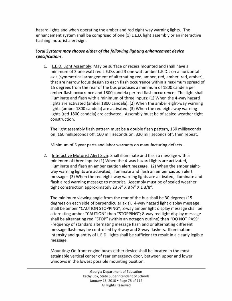
Georgia Department of Education Kathy Cox, State Superintendent of Schools
January 15, 2010 • Page 75 of 112 All Rights Reserved
hazard lights and when operating the amber and red eight way warning lights. The enhancement system shall be comprised of one (1) L.E.D. light assembly or an interactive flashing motorist alert sign.
Local Systems may choose either of the following lighting enhancement device
specifications.
1. L.E.D. Light Assembly: May be surface or recess mounted and shall have a minimum of 3 one watt red L.E.D.s and 3 one watt amber L.E.D.s on a horizontal axis (symmetrical arrangement of alternating red, amber, red, amber, red, amber), that are narrow focus design so each flash occurrence within a maximum spread of 15 degrees from the rear of the bus produces a minimum of 1800 candela per amber flash occurrence and 1800 candela per red flash occurrence. The light shall illuminate and flash with a minimum of three inputs: (1) When the 4-way hazard lights are activated (amber 1800 candela). (2) When the amber eight-way warning lights (amber 1800 candela) are activated. (3) When the red eight-way warning lights (red 1800 candela) are activated. Assembly must be of sealed weather tight construction.
The light assembly flash pattern must be a double flash pattern, 160 milliseconds on, 160 milliseconds off, 160 milliseconds on, 320 milliseconds off, then repeat.
Minimum of 5 year parts and labor warranty on manufacturing defects.
2. Interactive Motorist Alert Sign: Shall illuminate and flash a message with a
minimum of three inputs: (1) When the 4-way hazard lights are activated, illuminate and flash an amber caution alert message. (2) When the amber eight-way warning lights are activated, illuminate and flash an amber caution alert message. (3) When the red eight-way warning lights are activated, illuminate and flash a red warning message to motorist. Assembly must be of sealed weather tight construction approximately 23 ½” X 8 ¾” X 1 3/8”.
The minimum viewing angle from the rear of the bus shall be 30 degrees (15 degrees on each side of perpendicular axis). 4-way hazard light display message shall be amber “CAUTION STOPPING”; 8-way amber light display message shall be alternating amber “CAUTION” then “STOPPING”; 8-way red light display message shall be alternating red “STOP” (within an octagon outline) then “DO NOT PASS”. Frequency of standard alternating message flash and or alternating different message flash may be controlled by 4-way and 8-way flashers. Illumination intensity and quantity of L.E.D. lights shall be sufficient to result in a clearly legible message.
Mounting: On front engine buses either device shall be located in the most attainable vertical center of rear emergency door, between upper and lower windows in the lowest possible mounting position.

Georgia Department of Education Kathy Cox, State Superintendent of Schools
January 15, 2010 • Page 76 of 112 All Rights Reserved
On rear engine buses either device shall be vertically centered and horizontally adjacent to the left and right upper brake lights.
Minimum of 5-year parts and labor warranty on manufacturing defects.
Step Well Lamp - Step well lamp(s) shall be actuated when the service door is opened.
Stop and Taillights – Large – A 38 square inch plain red lamp shall be mounted on each side of the rear of the bus body just inside the turn signals. The stoplights shall be wired into the chassis stop light circuit. Lamps can be incandescent or LED.
Stop and Taillights – Small - Each bus shall be equipped with two-combination tail and stop lights emitting a red light plainly visible for 500 feet. One taillight shall be mounted on the left side of the rear of the bus body above the license holder and the other at approximately the same position on the right side of the rear of the bus body. The taillights shall be wired into the chassis lighting system. The taillights shall have the ability to illuminate the bus license plate. If recess taillights are used, a separate license plate lamp must be provided. Lamps can be incandescent or LED.
Strobe Light - A white flashing strobe shall be installed on the roof of the school bus in the second roof panel approximately four feet forward from the rear of the roof edge. Light shall have a single clear lens emitting light 360 degrees around its vertical axis and may not extend above the roofline more than 4 1/2 inches. The roof-mounted strobe shall be wired so that it is activated by the manual 8-lamp flasher light switch and deactivated when the entrance door is closed. The system must also have an auxiliary switch to permit the operator to turn the light on in inclement conditions without activating the 8-light system. A pilot light must be included to indicate when light is in operation. Strobe light shall meet SAE J575 and J1318 specifications.
A Brush Guard that will not interfere with light’s appearance or function must be used to protect the Strobe Light Assembly.
NOTE – In the event that a roof top mounted air conditioning condenser interferes with the specified location of the strobe light, the following options are approved for the local school system:
- Install two strobes with one in front of the condenser and one behind the condenser
- Install a standard design/profile strobe on top of the condenser (could result in a height issue)
- Install a remote mounted power pack strobe with reduced profile on top of the condenser
Turn Signal Lights - The front two directional signals shall be Fender-Mounted or Cowl Mounted directional signals in compliance with Federal Regulations. The bus shall be equipped with two side-mounted directional lights mounted on the side toward the front

Georgia Department of Education Kathy Cox, State Superintendent of Schools
January 15, 2010 • Page 77 of 112 All Rights Reserved
of the bus; one near the stop signal arm on the left and one on the right side to the rear of service door of the bus.
The rear two 38 square inch lights with an amber arrow on the inside of the lens shall be face mounted. These turn signals shall be mounted just under the windows on the outside corners of the rear of the bus. Lamps can be incandescent or LED. When LED turn signals are used, arrows are not required.
31. Manuals/Catalogs - With each order, the successful bidder shall provide Chassis, Body, Electrical, Parts and Service hard copy manuals, or CD’s, or Internet access as required by the LEA.
32. Mirrors
Each school bus shall be equipped with a system of exterior mirrors (as defined in FMVSS 111.)
Cross View Mirror System: Each school bus shall be equipped with a system of cross view mirrors (as defined in FMVSS 111.)
a. The cross view mirror shall provide an image of the prescribed area around the bus that is easily discernible for the driver.
b. The cross view mirror system shall minimize or eliminate the potential introduction of glare to the driver’s field of vision from the cross view mirror.
c. The cross view mirror system shall offer removable, readily replaceable lenses for quick and simple replacement of scratched and/or damaged mirror lenses.
d. This system of mirrors shall be easily adjustable but be rigidly braced so as to reduce vibration. The cross view mirror system shall also provide drivers of varying heights the field of vision prescribed in the aforementioned standard.
e. The cross view mirror system when mounted on fiberglass/composite bodies shall include bell style mounts at each brace arm mounting location for increased mounting integrity. In addition, either the bell plate or the bell bracket plate shall incorporate a tubular protective sleeve or other design protection to prevent direct contact of the mounting bolt threads with the fiberglass fender when mounted.
Purchaser’s Option: Buses can be equipped with heated cross view mirrors.
Interior Mirror - One rear view non-glare mirror 6 inches x 30 inches in size, having a metal frame and back, shall be securely attached on the windshield header and so located as to give the driver a clear view of the entire interior of the bus and road behind. Buses equipped with tinted windows may use a clear mirror of the same size.

Georgia Department of Education Kathy Cox, State Superintendent of Schools
January 15, 2010 • Page 78 of 112 All Rights Reserved
Side/Rear Vision Mirror System - Each school bus shall be equipped with a system of exterior mirrors (as defined in FMVSS 111.)
a. Side/rear vision mirror: The mirror system shall be capable of providing a view along the left and right sides of the vehicle, which will provide the driver with a view of the rear tires at ground level.
b. The side/rear vision mirror system shall be comprised of four (4) independent mirror assemblies with one (1) flat mirror glass assembly a minimum of 7 3/8” wide with a minimum of 73.75 squire inches in total area and one (1) convex mirror glass assembly a minimum of 7 3/8” wide with a minimum 73.75 square inches in total area located on each side of the bus.
c. The side/rear vision mirror lens must be remote adjustable, within the mirror assembly, on both the vertical and horizontal axis.
d. The side/rear vision mirror system shall have 1” primary mounting arms and be rigidly braced yet still allow for simple and easy adjustment.
Exception: “b” & “d” not required on rear engine transits.
Purchaser’s Option: Buses can be equipped with heated side/rear vision mirrors.
33. Pre-Delivery Service - The Georgia Pre-Delivery Service Form shall be completed by the school bus manufacturer in conjunction with the local dealer in addition to the manufacturer or dealer pre-delivery form. Manufacturer direct sales are required to complete the Georgia Pre-Delivery Service Form at the manufacturing plant. A copy of the completed Georgia Pre-Delivery Service Form for each complete school bus is to be provided to the local school system at time of delivery (see pages 95-96).
Delivery Inspection - The school bus manufacturer’s or school bus supplier’s representative or agent must guarantee the complete school bus to be free of damage upon delivery. If the school bus has damage at delivery, the local school system shall note damage in writing on delivery receipt. Damage refers to physical damage present at time of delivery and does not include any warrantable defects. Warrantable defects shall be addressed as expediently as possible.
34. Projections – The interior of the bus shall be free of all unnecessary projections, which include luggage racks and attendant handrails, in order to minimize the potential for injury. Buses may be equipped with under body storage compartments on either side of the bus body.
35. Reflectors - Two amber and four red reflectors with a 3-inch minimum diameter shall be installed. These reflectors may be plastic type mounted in or on aluminum or plastic frames and shall be installed on the bus body using a suitable rivet or screw fastener. If self-adhesive reflectors are used, only 3M Diamond Grade #988 RED and AMBER reflectors

Georgia Department of Education Kathy Cox, State Superintendent of Schools
January 15, 2010 • Page 79 of 112 All Rights Reserved
meeting SAE Standard J594 will be accepted. All reflector installations shall meet Federal Safety Standards FMVSS 108.
36. Seatbelt Cutter – Each bus shall be equipped with a durable webbing cutter having a full width handgrip and a protected, replaceable or non-corrodible blade. The required belt cutter shall be mounted in a location accessible to the driver in an easily detachable manner.
37. Seating -
NOTE: FMVSS 222 calls for seat back height to be 20” above the seating reference design point. In 2005 the National Specifications were changed to 24” above the seat reference point. The Georgia specification reflects the National Specifications with some additions/ clarifications. (This will result in a 4” higher seat back.)
NATIONAL SPECIFICATIONS ON SEATS AND RESTRAINING BARRIERS
A. Passenger Seating
1. School bus designed capacities shall be in accordance with 49 CFR, Part 571.3,
Definitions, and FMVSS No. 222, School Bus Passenger Seating and Crash Protection. 2. All seats shall have a minimum cushion depth of 15 inches, a seat back height of 24
inches above the seating reference point, and must comply with all other requirements of FMVSS No. 222. In addition to the fastener that forms the pivot for each seat retaining clip, a secondary fastener may be used in each clip to prevent the clip from rotating and releasing the seat cushion unintentionally.
3. All restraining barriers and passenger seats shall be constructed with materials that
enable them to meet the criteria of the School Bus Seat Upholstery Fire Block Test.
4. Each seat leg shall be secured to the floor by a minimum of 2 bolts, washers and nuts. Flange-head nuts may be used in lieu of nuts and washers, or seats may be track-mounted in conformance with FMVSS No. 222. If tract seating is installed, the manufacturer shall supply minimum and maximum seat spacing dimensions (applicable to the bus) which comply with FMVSS No. 222. This information shall be on a label permanently affixed to the bus.
5. All seat frames attached to the seat rail shall be fastened with 2 or more bolts, washers
and nuts, or with flange-head nuts.
6. All school buses (including Type A) shall be equipped with restraining barriers which conform to FMVSS No. 222.
7. A flip-up seat may be installed at any side emergency door. If provided, the flip-up
seat shall conform to FMVSS No. 222 and aisle clearance requirements of FMVSS No.

Georgia Department of Education Kathy Cox, State Superintendent of Schools
January 15, 2010 • Page 80 of 112 All Rights Reserved
217, Bus Emergency Exits and Window Retention and Release. The flip-up seat shall be free of sharp projections on the underside of the seat bottom. The underside of the flip-up seat bottoms shall be padded or contoured to reduce the possibility of clothing being snagged. Flip-up seats shall be constructed to prevent passenger limbs from becoming entrapped between the seat back and the seat cushion when the seat is in the upright position. The seat cushion shall be designed to rise to a vertical position automatically when it is not occupied.
8. Lap belts shall not be installed on passenger seats in large school buses (over 10,000
pounds GVWR) except in conjunction with child safety restraint systems that comply with the requirements of FMVSS No. 213, Child Restraint Systems.
GEORGIA REQUIREMENTS
Passenger Seats - The backside of all pupil seats shall be constructed alike except that the rear row of seats is not required to meet the forward and rearward performance of dynamic requirements of FMVSS 222. Seats shall be forward facing and shall be spaced to obtain a minimum of 24-inch hip to knee room measured horizontally at seat cushion level at the transverse centerline of seat. (Greater seat spacing may be specified on local bids not to exceed the maximum allowable per FMVSS 222.) All seats shall be 39 inches wide and approximately 15 inches deep except for left rear seat, which may be 26 inches to provide for emergency egress as required by FMVSS 217. Right front seats may be 26 inches to allow for additional entrance aisle space. Seats shall be arranged to provide a minimum of 12 inches aisle space. School bus designed capacities shall be in accordance with 49 CPR, Part 571.3, Definitions, and FMVSS No. 222, School Bus Passenger Seating and Crash Protection.
Exception: Type A-1 and Type B vehicles may use seats less than 39 inches.
Seat frames may be equipped with attachments or devices (seat belt ready seats) to which seat belts, restraining harnesses or other devices may be attached. Attachment framework or anchorages devices, if installed, shall conform to FMVSS210.
If a local school system elects to utilize school buses equipped with 3-point lap/shoulder passenger seat belts, a 12” minimum aisle must be maintained. Thirty nine inch seat widths are not required when utilizing three point lap/shoulder passenger seat belts.
Passenger Seat Cushions - Seats and back cushions of all seats shall be designed to safely support designated number of pupils under normal road conditions encountered in school bus service. Seat, seat back cushion, crash barrier, header pads, and the underneath portion of the seat shall be covered with an Aramid Kevlar, Proform or approved equivalent fire block material having 42-ounce finished weight, 54-inch width, and finished vinyl coating of 1.06 broken twill or other material with equal tensile strength, tear strength, seam strength, adhesion strength, resistance to abrasion, resistance to cold, and flex separation. All padding and coverings must be of fire-resistant material meeting

Georgia Department of Education Kathy Cox, State Superintendent of Schools
January 15, 2010 • Page 81 of 112 All Rights Reserved
FMVSS 302. Seats shall be padded to meet FMVSS 222. Back cushions shall be constructed so as to eliminate exposed screws or bolts, which contribute to vandalism.
Passenger Seat Frame and Mounting - Seat mounting shall meet FMVSS 222.
38. Seating Capacity - Below are the definitions of seating capacity as defined by Georgia School Bus Specifications:
Designed Seating Capacity – The theoretical passenger capacity that a vehicle of that body shell size would have if it were constructed with the maximum number of seating positions per FMVSS 222.
Equipped Capacity – The number of designated seating positions provided in a new bus per manufacturer’s body/seating plan.
In-Use Seating Capacity - See Part 9 – Appendices
39. Steering Wheel – There shall be a distance of at least 2 inches between steering wheel and cowl, instrument panel, windshield, and any other surface.
40. Stop Arm – There shall be installed on the left outside of the body an electric-operated reflectorized stop arm equipped high intensity flashing L.E.D. (Light Emitting Diode) lights, strobing L.E.D. or strobe lights, which shall be connected to the alternately red flashing signal lamp circuits. The stop arm shall be of an octagonal shape with high intensity, reflectorized sheeting of white letters and border and a red background meeting FMVSS 131 and sheeting shall be warranted for 10 years.
Purchaser Option: A second stop arm can be located at the rear of the bus on the driver’s side. The second stop arm shall have the same specifications as the stop arm described in Item 38, only on the side facing traffic overtaking the school bus from the rear.
Purchaser Option: Air-operated stop sign: Valve to operate device shall actuate switch through a solenoid to operate flasher stop lights and stop arm lights. Line fittings shall be brass. Buses equipped with air accessories shall be equipped with a pressure protection valve between the air source and the air accessories.
41. Sun Visor - The minimum size of the transparent sun visor is to be 6 inches x 30 inches. The sun visor shall be securely mounted to the body above the windshield and double mounted in a heavy-duty adjustable bracket.
42. Tail Pipe - The tailpipe may be flush with, or shall not extend more than 2 inches beyond, the perimeter of the body for side-exit pipe or the rear bumper for rear-exit pipe.
43. Tow Hooks - Rear - The body shall be equipped with rear tow hooks, attached to the frame so as not to project beyond the rear bumper.
44. Training – See page 47.

Georgia Department of Education Kathy Cox, State Superintendent of Schools
January 15, 2010 • Page 82 of 112 All Rights Reserved
45. Warranty – Complete School Bus – School Bus Suppliers are to state their standard warranty on their bid proposal and any additional or extended warranty on components. The current school bus supplier is responsible for the resolution of all warranty claims during the warranty period of the complete school bus for any part, component or accessory required by National Specifications and Georgia School Bus Specifications. Body and chassis manufacturers’ warranty policies shall allow (but not be required) revision of warranty start date for each vehicle to the actual in-service date by the school district. School bus suppliers will list in their bid proposal to the local school district, the local vendor that will be responsible for the warranty claims on the units that they represent. School bus suppliers will not list multiple engine, chassis and body repair facilities. Each supplier will provide a primary facility that will be responsible for the “entire” complete school bus.
Purchaser’s Option: Local school districts may specify extended warranties on school
buses for the chassis and body that they purchase. Towing warranties are available that may cover the cost of towing to the recommended repair facility of the school bus during the vehicle’s warranty period. These extended warranties are available at additional cost.
46. Windshield Cleaning Steps - A folding windshield step and a convenient chrome, other non-corrosive metal, or equivalent non-corrosive material handle shall be installed on each side of the body on lower section of cowl for easy accessibility for cleaning the windshield. The handle shall be a heavy-duty handle, approximately 8 inches in length with 1 1/2 inch clearance. The handle shall be attached to the bus by four non-corrosive metal fasteners.
Exception: Transit - windshield step may be in or on top of front bumper.
47. Windshield Wipers and Washers - Bus shall be equipped with one (1) or two (2) windshield wiper motors controlled by a single switch. Each wiper motor shall have two (2) speeds and intermittent feature. The design of the wiper shall be such to afford the maximum wiped area and good driver view. If a single wiper motor is used, the system shall meet the requirements of SAE standard J198.
Exception: Transit buses shall be equipped with a minimum of 24-inch windshield wiper arm and a minimum 17-inch blade.
An electric, or air-operated windshield washer shall be furnished and installed and shall be activated by means of a dashboard mounted switch. The water reservoir shall be made of rigid plastic and shall be mounted under the hood on the conventional and metropolitan or in the driver’s compartment on the transit. The container shall have a minimum capacity of two quarts.
The windshield washer nozzle shall direct a continuous stream of water into the path of the wiper blades until the mechanism is turned off.
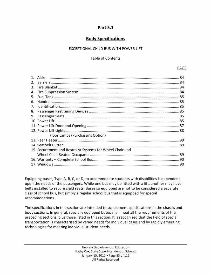
Georgia Department of Education Kathy Cox, State Superintendent of Schools
January 15, 2010 • Page 83 of 112 All Rights Reserved
Part 5.1
Body Specifications
EXCEPTIONAL CHILD BUS WITH POWER LIFT
Table of Contents
PAGE
1. Aisle ............................................................................................................................. 84 2. Barriers ............................................................................................................................ 84 3. Fire Blanket ..................................................................................................................... 84 4. Fire Suppression System ................................................................................................. 84 5. Fuel Tank ......................................................................................................................... 85 6. Handrail ........................................................................................................................... 85 7. Identification ................................................................................................................... 85 8. Passenger Restraining Devices ....................................................................................... 85 9. Passenger Seats .............................................................................................................. 85 10. Power Lift ........................................................................................................................ 85 11. Power Lift Door and Opening ......................................................................................... 87 12. Power Lift Lights.............................................................................................................. 88
Floor Lamps (Purchaser’s Option) 13. Rear Heater ..................................................................................................................... 89 14. Seatbelt Cutter ................................................................................................................ 89 15. Securement and Restraint Systems for Wheel Chair and
Wheel Chair Seated Occupants ...................................................................................... 89 16. Warranty – Complete School Bus ................................................................................... 90 17. Windows ......................................................................................................................... 90
Equipping buses, Type A, B, C, or D, to accommodate students with disabilities is dependent upon the needs of the passengers. While one bus may be fitted with a lift, another may have belts installed to secure child seats. Buses so equipped are not to be considered a separate class of school bus, but simply a regular school bus that is equipped for special accommodations. The specifications in this section are intended to supplement specifications in the chassis and body sections. In general, specially equipped buses shall meet all the requirements of the preceding sections, plus those listed in this section. It is recognized that the field of special transportation is characterized by varied needs for individual cases and by rapidly emerging technologies for meeting individual student needs.

Georgia Department of Education Kathy Cox, State Superintendent of Schools
January 15, 2010 • Page 84 of 112 All Rights Reserved
NOTE: Where there is conflict between Georgia and Federal Motor Vehicle Safety Standards, Federal Specifications shall prevail. Buses must meet Georgia Specifications to the extent that National School Transportation Specifications and Procedures are exceeded or the item is specifically addressed; otherwise, 2005 National School Transportation Specifications and Procedures are considered as a minimum.
NOTE: Items listed as Purchaser’s Options must be specifically requested by the local school system.
The following specifications are for buses used as an Exceptional Child Bus where a power lift will be necessary in the transportation of students with disabilities.
Bus body structure and equipment shall conform to Georgia Chassis and Body Specifications - Conventional, Transit, and Small School Buses approved by the State Board of Education except for modifications necessary for installation of special equipment listed herein.
Any school bus purchased for the transportation of physically handicapped children shall be equipped with a power lift. Lift shall be located on right side of the body, in no way attached to the exterior but confined within the perimeter of the standard school bus body.
1. Aisle - The aisle leading from the wheelchair position to at least one exit door and the lift area shall be a minimum of 30 inches to allow a wheelchair to be moved between the two rows of seats in the event an emergency evacuation of the bus is necessary.
2. Barriers
a. There shall be a padded barrier in front of all forward-facing passenger seats that do not have another seat in front of it. The barrier shall meet FMVSS 222. Kick/modesty panels shall be installed between the bottom of the barrier(s) and the floor and between the leg(s) and wall to ensure that pupils will not slip under the barriers.
b. There shall be either a seatback, FMVSS barrier, or padded stanchion with modesty panel in front of the forward most wheelchair position.
3. Fire Blanket – Each exceptional child bus equipped with a wheel chair lift shall be equipped with a fire blanket. The fire blanket shall be of a wool/synthetic design that meets the ASTM D4151-92 Flammability of Blankets Class I standard. The blanket shall have a minimum of 56” and have a minimum of 4960 square inches in total area and will be stored in a vinyl pouch mounted in an accessible location in the bus body. Note: Evacuation type portable stretchers (vinyl with handles) are not to be substituted for a fire blanket but may also be specified by the LEA in addition to the fire blanket.
4. Fire Suppression System - The engine compartment shall be protected by a fire suppression system. The system shall be triggered by electronic activation through a control panel that provides an audible and visual alarm. The control panel shall be located within view and

Georgia Department of Education Kathy Cox, State Superintendent of Schools
January 15, 2010 • Page 85 of 112 All Rights Reserved
easy reach of the driver. The control panel shall supervise all suppression circuits. The fire suppressant chemical shall be Purple K (dry type), ABC (dry type) or FE-36 (liquid clean agent). A pressure gauge, light or monitor shall be mounted within the driver’s compartment area to monitor the status of the charged chemical canister. If a light or monitor is utilized, a pressure gauge must still be provided at the charged chemical canister. The fire suppression system shall be capable of being activated whether the engine is running or not. The complete fire suppression system shall be warranted for a minimum of one year. The fire suppression manufacturer must supply a written certification report that is specific to each application of installation to the GaDOE annually through the school bus supplier for buses bid under newly adopted specifications.
The fire suppression system shall not have a vehicle shut down system. A placard shall be placed in clear view of the driver “IN CASE OF FIRE, STOP VEHICLE, SHUT OFF ENGINE” and any necessary instruction providing further driver directions.
Purchaser’s Option – Control panel can have a manual means of actuation accessible to the driver.
5. Fuel Tank - A fuel tank meeting FMVSS 301 mounted on the left or right side of chassis frame or between chassis frame rails will be furnished by the chassis manufacturer.
6. Handrail –Handrails and mounting shall be designed to minimize the possibility of student’s clothing or personal items from becoming lodged or caught while exiting the bus as evidenced by the passing of the NHTSA string and nut test. Purchaser’s Option: School districts may wish to add an additional handrail in the entrance area of the bus body to assist students with disabilities in gaining better access and ability to enter and exit the bus.
7. Identification – Specially equipped school buses shall display the International Symbol of Accessibility below the window line. Such emblem shall be white on blue or black background, shall not exceed 12 inches square in size and shall be of a high-intensity retro reflective material meeting the requirements of Federal Highway Administration (FHWA) FP-85, Standard Specifications for Construction of Roads and Bridges on Federal Highway Projects.
8. Passenger Restraining Devices - When restraining devices are specified, one shall be provided for each seated passenger. Buckles must be non-reflective.
9. Passenger Seats - All passenger seats shall be forward facing. Track seating that meets standard FMVSS 222 is acceptable. Seat frames may be equipped with attachments or devices to which seat belts (seat belt ready seats), restraining harnesses or other devices may be attached. Attachment framework or anchorages devices, if installed, shall conform to FMVSS210.
10. Power Lift – Must meet or exceed FMVSS 403 and 404 Standards and comply with current specifications set forth in the National School Bus Standards.

Georgia Department of Education Kathy Cox, State Superintendent of Schools
January 15, 2010 • Page 86 of 112 All Rights Reserved
a. Design Load – The design load of the lift shall be at least 800 pounds. Working parts, such as cables, pulleys and shafts, which can be expected to wear, and upon which the lift depends for support of the load, shall have a safety factor of at least six, based on the ultimate strength of the material. Non-working parts, such as platform, frame and attachment hardware that would not be expected to wear, shall have a safety factor of at least three, based on the ultimate strength of the material.
b. Lift Capacity – The lifting mechanism and platform shall be capable of operating effectively with 1,000 pounds of tested lifting capacity and 800 pounds of continuous lifting capacity.
c. Unit or lift must be of a standard make by a national known manufacturer and approved by the Department of Education. The power supply for the lift shall be a 12 volt electric/hydraulic system that is circuit breaker protected, operating two single-acting hydraulic cylinders. The maximum average amperage draw shall be 95 amps when lifting a load of 800 pounds from ground to vehicle floor. All hydraulic oil hoses must conform to or be better than SAE Specification 100-R3. Hose fittings and metal hydraulic lines shall be made of material other than galvanized pipe. The electric motor for the hydraulic pump must have a duty cycle 1:1. The drive motor and hydraulic pump shall not interfere with the movement of wheelchairs through the bus aisle. It shall be enclosed to prevent transported students from coming in contact with the unit and it shall be readily accessible to service personnel for routine service and for maintenance.
No lift shall be mounted in the rear of the bus or blocking an emergency exit.
Any vendor marketing lifts in Georgia shall guarantee repair or replacement parts availability within 72 hours of notice.
d. The lift platform shall provide for power operation up and power or gravity-down. Gravity-down lifts must have a pressure compensated valve located at the end of the cylinder; the time period for descent shall be a minimum of 6 seconds. When the lift platform is in the fully up position, it shall be locked in position mechanically by means other than a support, or lug, on the door. The lift mechanism shall be equipped with adjustable limit switches and/or by-pass valves to prevent excessive pressure from building in the hydraulic system when the platform reaches the full up position or the ground. The lift travel shall be as near vertical as possible according to lift design. A swing arm design that travels in an arc is not acceptable.
e. Lift platform shall conform to door and floor opening. All edges of platform shall be designed to restrain wheelchairs and operator’s feet from becoming entangled during raising and lowering process. Platform ends shall be fitted with full-width shields, which extend above floor when lift platform is in lowered position.
f. Lift platform shall have a minimum size of 44 inches in length, width shall be capable of accommodating a 30-inch cube, and shall be equipped with folding handrails.

Georgia Department of Education Kathy Cox, State Superintendent of Schools
January 15, 2010 • Page 87 of 112 All Rights Reserved
g. Power lifts shall be so equipped that they may be manually raised in the event of power failure of the power lift mechanism, and must be capable of raising a 400-pound load.
h. Platform floor surface is to be covered with ribbed-surfaced rubber, l/8” minimum thickness, RCA or approved equal, except when platform is made of expanded metal. Edges of platform and adjacent floor shall be properly finished and all seams covered with molding as required for bus floor. Flexible seals designed to keep dirt, water and fumes out when in a locked position shall be installed along platform edges.
i. A self-adjusting, non-skid metal ramp of a width to minimize incline to lift platform and of sufficient strength to support the front wheels of a wheelchair with student shall be hinged to door side of lift platform. Control over lowering and placement of ramp shall be convenient to attendant when standing on platform. When installed in bus bodies longer than 20 feet, it shall be power operated.
j. Positioning of power unit shall be controlled by momentary type switch mounted within bus and adjacent to lift, convenient to attendant when standing upon lift platform and when the lift is in any position. An actuating switch shall be installed in the circuit so that the lift mechanism will not operate when the lift platform doors are closed.
k. With the exception of floor molding, no metal screws are to be used in fabrication of platform assembly.
The attached inspection checklist found on pages 97 and 98 must be completed and signed by the bus dealer upon delivery of the new bus to make sure that the lift is operating in a way that is set forth by the FMVSS-403 operational checks.
11. Power Lift Door and Opening -
Power Lift Door
a. All doors must open only in a manner which shall not interfere with the normal operation of the entrance door or obstruct the entrance or exit of students through the entrance door.
b. If body opening extends through body skirt, doors shall extend to bottom of body skirt. When ramps are used, door or doors shall extend from window header to below floor line covering the ramp container.
c. All doors shall be weather sealed and so constructed that a flange on the forward door overlaps the edge of rear post or door when closed. Design shall provide positive means of holding door, or doors, in open position during lift operation. Friction type catches are not acceptable.

Georgia Department of Education Kathy Cox, State Superintendent of Schools
January 15, 2010 • Page 88 of 112 All Rights Reserved
d. When manually operated dual doors are provided, the rear door shall have at least a one-point fastening arrangement to the header or floor line of the body. The forward-mounted door shall have at least three one-point fastening devices. One shall be to the header, one to the floor line of the body, and the other shall be into the rear-mounted door. The door shall be securely hinged with one piano type or two heavy-duty pin-type hinges and shall open outward. The door and hinge mechanism shall have strength that is greater than, or equivalent to, the strength of the emergency exit door. When single door is used, locking device shall meet requirements for emergency door lock.
e. All doors shall have positive fastening devices to hold doors in the open position.
f. Door materials, panels and structural strength shall be equivalent to the conventional service and emergency doors. Color, rub rail extensions, lettering, and other exterior features shall match adjacent sections of the body.
g. Each door shall have glass window set in a fully water tight manner, compatible with and set to the lower line of adjacent sash.
h Doors shall be equipped with a device that will actuate an audible or visible signal located in the driver’s compartment when not securely closed.
Power Lift Opening
a. Door posts, headers and floor sections around this special opening shall be reinforced to provide strength and support equivalent to adjacent sidewall and floor construction of an unaltered model.
b. Inside of door header shall be padded with a pad of at least 3 inches wide and one inch thick and extend the full width of the door.
c. A drip molding shall be installed above opening so as to effectively spill water from entrance.
12. Power Lift – Lights - Two lights shall be provided for the lift, one located inside the bus over the special service door and one located in the skirt near the lift, to provide light for the lift platform when lowered. The exterior light shall be a minimum of 3 l/2 inches, comparable to the backup lights, and both lights shall be operated from a single switch located in the door area.
Purchaser’s Option – Floor Lamps: Bus body shall be equipped with a 3” x 6 ¾” dome light assemblies that are flush mounted to the body interior, 12” from the interior floor. Each floor light will be in sequence with the overhead location of the interior dome light in wheelchair position areas. Lighting to be used will be either incandescent or L.E.D. lamps with lenses that are secured with screws. Floor lighting will be activated by a switch

Georgia Department of Education Kathy Cox, State Superintendent of Schools
January 15, 2010 • Page 89 of 112 All Rights Reserved
located in the driver’s switch panel, separate from the interior dome light switch and by opening the lift door.
13. Rear Heater – The rear heater shall be designed and installed so as not to cause dangerous
overheating conditions which could cause harm to passengers, seated or secured in wheel chairs. The rear heater shall be at least 50,000 B.T.U. The purchaser has the option to specify installation location.
14. Seatbelt Cutter – Each bus shall be equipped with a durable webbing cutter having a full width handgrip and a protected, replaceable or non-corrodible blade. The required belt cutter shall be mounted in a location accessible to the driver in an easily detachable manner. It is suggested that multiple seat belt cutters be located within the bus body interior to aid with emergency student evacuation.
15. Securement and Restraint Systems for Wheel Chair and Wheel Chair Seated Occupants
a. Body shall be designed for positioning and securement of mobile seating devices and occupants in a forward-facing orientation. Securement system hardware and attachment points for the forward- facing system shall be provided.
b. Mobile seating device securement system shall utilize four-point tie- downs, with a minimum of two body floor attachment points located at the rear of the space designated for the mobile seating device and a minimum of two body floor attachment points at the front of the space.
c. A Type 2 occupant securement system shall provide for securement of the occupant’s pelvic lap area and upper torso area, with height adjustable shoulder restraint.
d. The mobile seating device/occupant securement system shall be successfully dynamically sled-tested at a minimum impact speed/force of 30 mph/20 G’s. The dynamic test shall be performed using system components and hardware (including attachment hardware), which are identical to the final installation in type, configuration, and positioning. The body structure at the attachment points may be simulated for the purpose of the sled test, but the simulated structure used to pass the sled test may not exceed the strength of the attachment structure to be used in the final body installation. The mobile seating device used for test purposes shall be a 150 pound powered wheelchair and the occupant shall be a 50th percentile male test dummy as specified in SAE – J2249. Measurements shall be made on the test dummy during the test for head acceleration, upper thorax acceleration, and upper leg compressive force. These measurements shall not exceed the upper limits set forth in FMVSS Part 571.208, S6.1.2, 6.1.3, and 6.1.4. The test dummy shall be retained within the securement system throughout the test and forward excursion shall be such that no portion of the test dummy’s head or knee pivot point passes through a vertical transverse plane intersecting the forward-most point of the floor space designated for the mobile seating device. All hardware shall remain positively attached throughout the test and there shall be no failure of any component. Each mobile seating device
Georgia Department of Education Kathy Cox, State Superintendent of Schools
January 15, 2010 • Page 90 of 112 All Rights Reserved
belt assembly including attachment hardware and anchorages shall be capable of withstanding a force of not less than 2,500 pounds. This will provide equal mobile seating device securement when subjected to forces generated by forward, rear or side impact.
The belt materials at each space designated for the mobile seating device and the occupant restraint system shall be similar in size and fabric.
e. Occupant securement belt assemblies and anchorages shall also be certified to meet the requirements of FMVSS 209 and 210.
f. The occupant securement system must be designed to be attached to the bus body either directly or in combination with the mobile seating device securement system, by a method, which prohibits the transfer of weight or force from the mobile seating device to the occupant in the event of an impact.
g. All securement system attachments or coupling hardware not permanently attached shall be a “positive latch” type or hook with automatic self-tensioning and self locking retractors, to prohibit accidental disconnecting.
h. All attachment or coupling systems designed to be connected or disconnected frequently shall be accessible and operable without the use of tools or other mechanical assistance.
i. All securement system hardware and components shall be free of sharp or jagged areas and shall be a non-corrosive material or treated to resist corrosion.
j. The occupant securement system shall be made of materials, which do not stain, soil, or tear an occupant’s clothing.
k. No mobile seating device securement system hardware shall be placed so that a mobile seating device can be placed blocking access to lift door.
l. The following information shall be provided with each vehicle equipped with a securement system.
(1) Detailed instructions, including a parts list, regarding installation and use of the system.
(2) Detailed instructions, including a diagram, regarding the proper placement and positioning of the system, including correct belt angles.
16. Warranty – Complete School Bus - See page 82 for specification on the complete school bus warranty.
17. Windows - Systems may wish to specify tinted windows in Exceptional Child Bus.

Georgia Department of Education Kathy Cox, State Superintendent of Schools
January 15, 2010 • Page 91 of 112 All Rights Reserved
Note: When purchasing a lift bus, the width and length of the lift platform should be sufficient to accommodate the types of wheelchairs used.
Buses with flat floors must be equipped with low-profile tires.
Georgia Department of Education Kathy Cox, State Superintendent of Schools
January 15, 2010 • Page 92 of 112 All Rights Reserved
Part 5.2
Body Specifications
EXCEPTIONAL CHILD BUS WITHOUT POWER LIFT
Table of Contents
PAGE
1. Barriers ............................................................................................................................ 93 2. Handrail ........................................................................................................................... 93 3. Passenger Restraining Devices ........................................................................................ 93 4. Passenger Seats ............................................................................................................... 93 5. Seatbelt Cutter ................................................................................................................ 93 6. Warranty – Complete School Bus ................................................................................... 93 7. Windows .......................................................................................................................... 93
Equipping buses, Type A, B, C, or D, to accommodate students with disabilities is dependent upon the needs of the passengers. While one bus may be fitted with a lift, another may have belts installed to secure child seats. Buses so equipped are not to be considered a separate class of school bus, but simply a regular school bus that is equipped for special accommodations. The specifications in this section are intended to supplement specifications in the chassis and body sections. In general, specially equipped buses shall meet all the requirements of the preceding sections, plus those listed in this section. It is recognized that the field of special transportation is characterized by varied needs for individual cases and by rapidly emerging technologies for meeting individual student needs.

Georgia Department of Education Kathy Cox, State Superintendent of Schools
January 15, 2010 • Page 93 of 112 All Rights Reserved
NOTE: Where there is conflict between Georgia and Federal Motor Vehicle Safety Standards, Federal Specifications shall prevail. Buses must meet Georgia Specifications to the extent that National School Transportation Specifications and Procedures are exceeded or the item is specifically addressed; otherwise, 2005 National School Transportation Specifications and Procedures are considered as a minimum.
NOTE: Items listed as Purchaser’s Options must be specifically requested by the local school
system.
The following specifications are for buses used as an Exceptional Child Bus where a power lift will not be necessary in the transportation of students with disabilities.
Bus body structure and equipment shall conform to Georgia Chassis and Body Specifications - Conventional, Transit, and Small School Buses approved by the State Board of Education except for modifications necessary for installation of special equipment listed herein.
1. Barriers- Kick/modesty panels shall be installed between the bottom of the barrier(s) and the floor and between the leg(s) and wall to ensure that pupils will not slip under the barriers.
2. Handrail –Handrails and mounting shall be designed to minimize the possibility of student’s clothing or personal items from becoming lodged or caught while exiting the bus as evidenced by the passing of the NHTSA string and nut test. Purchaser’s Option: School districts may wish to add an additional handrail in the entrance area of the bus body to assist students with disabilities in gaining better access and ability to enter and exit the bus.
3. Passenger Restraining Devices - When restraining devices are specified, one shall be provided for each seated passenger. Buckles must be non-reflective.
4. Passenger Seats - All passenger seats shall be forward facing. Track seating that meets standard 222 is acceptable. Seat frames may be equipped with attachments or devices to which seat belts (seat belt ready seats), restraining harnesses or other devices may be attached. Attachment framework or anchorages devices, if installed, shall conform to FMVSS210.
5. Seatbelt Cutter – Each bus shall be equipped with a durable webbing cutter having a full width handgrip and a protected, replaceable or non-corrodible blade. The required belt cutter shall be mounted in a location accessible to the driver in an easily detachable manner. It is suggested that multiple seat belt cutters be located within the bus body interior to aid with emergency student evacuation.
6. Warranty – Complete School Bus – See page 82 for specification on the complete school bus warranty.
7. Windows - Systems may wish to specify tinted windows in Exceptional Child Bus.

Georgia Department of Education Kathy Cox, State Superintendent of Schools
January 15, 2010 • Page 94 of 112 All Rights Reserved
Part 6
Vendor Requirements
1. A letter from the school bus supplier must be provided to the GaDOE annually for buses bid under newly adopted specifications. The letter is for certifying that their heater/defroster system on Type B, C & D buses meets or exceeds Georgia Specifications.
2. The fire suppression manufacturer must supply a written certification report that is specific to each application of installation to the GaDOE annually through the school bus supplier for buses bid under newly adopted specifications.
3. School bus suppliers will list in their bid proposal to the local school district, the local vendor that will be responsible for the warranty claims on the units that they represent.
4. School bus suppliers will provide in their bid proposal a complete school bus data/build detail sheet(s) with floor plan.
5. School bus suppliers are to state their standard warranty and any extended warranty on components on their bid proposal. (See page 82)
6. With each order, the successful bidder shall provide Chassis, Body, Electrical, Parts and Service hard copy manuals, or CD’s, or Internet access as required by the LEA.
7. A copy of the completed Pre-Delivery Service Form for each complete school bus is to be provided to the local school system at time of delivery.
8. The Power Lift Inspection Checklist must be completed and signed by the bus dealer upon delivery of the new lift bus.
9. The dealer/seller of the complete school bus shall provide training to the local school district’s designated fleet employees as prescribed on Type B, C & D buses. The training will be provided at the local school system’s fleet facility or at a regional location unless otherwise agreed upon by the local school district.
Georgia Department of Education Kathy Cox, State Superintendent of Schools
January 15, 2010 • Page 95 of 112 All Rights Reserved
Pupil Transportation
Pre-Delivery/Quality Inspection Report
Owner’s Name Engine # Vehicle Serial # Owner’s Address City, State, Zip Code Transmission # Axle # Dealer City, State, Zip Code Note: the following operations are to be performed and necessary adjustments
completed. Check applicable shop manuals for current specifications for all vehicles. Repair Order Inspection Code - S-Satisfactory A-Adjustment Made F-Fluid Low/Leaks R-Repairs Needed X-Inoperative/Missing
Service Description Code Service Description Code Service Description Code
Interior Inspection Verify or Inspect… 1. Doors, locks, latches, and adjustments
Under Hood Inspection Verify or Inspect… 18. Hood alignment, plus operation and
tightness of mounting hardware
Chassis Inspection 34. Brake hose clipping and clamp
tightness. Are hoses clear of; other hoses to prevent chafing, moving parts, sharp edges, and heat sources?
2. Floor mats, trim strips, and molding
19. Air filter element position and cover tightness
35. Fuel line clipping. Are lines clear of moving parts, sharp edges, and heat sources?
3. That operator’s manual is on vehicle
20. Air inlet pipe clearance 36. Tire air pressure. Fill to proper inflation
pressure
4. Operation of windows and vents
21. Tighten all air and coolant hose clamps 37. Tie rods and drag link. That cotter
keys/lock tabs are installed properly on all steering components
5. Seats and belts – operation and anchorage
22. Air and coolant hose clipping. Are hoses clear of; other hoses to prevent chafing, moving parts, sharp edges, and heat sources?
38. Front springs, clamps and shackles
6. Automatic transmission neutral safety switch operational if so equipped
23. Steering hose clipping and clamp tightness. Are hoses clear of; other hoses to prevent chafing, moving parts, sharp edges, and heat sources?
39. Power steering sector-tightness
7. Air/hydraulic brake pressure indicator lights and/or warning buzzer operation
24. Operation of heater cut-off valves
40. King pins
8. Hydraulic brake back-up motor 25. That wiring harnesses are clear of
moving parts, sharp edges, and heat sources
41. Front and rear shock absorbers
9. Park brake light operation 26. Starter/alternator cable end tightness,
battery cable routing, support and clearance
42. Rear springs, clamps and shackles
10. Horn, windshield wiper and washer operation
27. All drive belts
43. Drive shaft support bearings and universal joints
11. Heater and fan operation 28. Proper engine oil level 44. Body mounting bolts
12. Air conditioning fan and operation if so equipped
29. Proper automatic transmission level
45. Exhaust system
13. Operation of instruments and interior lights, stepwell lights
30. Proper coolant level and antifreeze protection level: record level ________
46. Lubricate chassis
Safety Devices 14. Stop arm, flasher lights and crossing
gate operation
31. DCA level: record level ________
Wheelchair Lift Bus 47. Lift operation/lubrication
15. First aid kit, fire extinguisher, body fluid clean up kit, flares
32. Proper power steering fluid level
48. Passenger restraints and seat belts
16. Turn signals, lights, light monitor, strobe light
33. Proper master cylinder fluid level
49. Lift door operation and door holder
17. Roof hatch, emergency windows operation and buzzers
50. Fire suppression system charged

Georgia Department of Education Kathy Cox, State Superintendent of Schools
January 15, 2010 • Page 96 of 112 All Rights Reserved
Pupil Transportation
Pre-Delivery/Quality Inspection Report
Owner’s Name Engine # Vehicle Serial # Owner’s Address City, State, Zip Code Transmission # Axle # Dealer City, State, Zip Code Note: the following operations are to be performed and necessary adjustments
completed. Check applicable shop manuals for current specifications for all vehicles. Repair Order Inspection Code - S-Satisfactory A-Adjustment Made F-Fluid Low/Leaks R-Repairs Needed X-Inoperative/Missing
Service Description Code Service Description Code Service Description Code
Operate Vehicle Operate vehicle for a sufficient time to stabilize engine coolant temperature. Verify satisfactory operation of… 51. Service brakes, steering and accelerator
systems
Note: Position vehicle and perform the following operations. Inspect for… 56. Exhaust leaks
Other Comments:
52. Speedometer/tachometer and all gauges
57. Fluid leaks
53. Heater/defroster, a/c, and ventilation system
Verify or Adjust… 58. Low idle speed
Inspected By:
54. Engine 59. Mirrors: rearview, sideview and
crosswalk
Lead Mechanic:
55. Transmission is automatic shift selector correct in all gears?
Any Repairs and/or Parts Needed Must Have a Repair Order Attached to this
Form. Date:

Georgia Department of Education Kathy Cox, State Superintendent of Schools
January 15, 2010 • Page 97 of 112 All Rights Reserved
Standard Power Lift Inspection Checklist

Georgia Department of Education Kathy Cox, State Superintendent of Schools
January 15, 2010 • Page 98 of 112 All Rights Reserved

Georgia Department of Education Kathy Cox, State Superintendent of Schools
January 15, 2010 • Page 99 of 112 All Rights Reserved
Evaluation for Engine Certification
Pupil Transportation
School System Bus Manufacturer Engine Model Number of Engines Terrain (circle one) METRO RURAL – (mixed) MOUNTAIN COSTAL – (flat) Bus Type (circle one) Conventional Transit Bus Capacity A.M. Route Length (miles) Total Averages Miles/Bus In-Service Date
Please rate (circle the following (1-Excellent 2-Very Good 3-Good 4-Fair 5-Poor)
Fuel Economy 1 2 3 4 5
Acceleration 1 2 3 4 5
Heater Performance 1 2 3 4 5
Emission Performance 1 2 3 4 5
Reliability 1 2 3 4 5
Engine Noise & Vibration 1 quiet 2 3 4 loud 5
Ease of Maintenance 1 2 3 4 5
Warranty Resolution 1 2 3 4 5
Driver Comments (required) Technician Comments (required) Director Comments (required)
Director Signature
Recommend to Approve (circle)
Return Completed Evaluation Directly to GaDOE Pupil Transportation Recommend to
Disapprove (circle)

Georgia Department of Education Kathy Cox, State Superintendent of Schools
January 15, 2010 • Page 100 of 112 All Rights Reserved
Evaluation for Transmission Certification
Pupil Transportation
School System Bus Manufacturer Transmission Model Number of Transmissions Terrain (circle one) METRO RURAL – (mixed) MOUNTAIN COSTAL – (flat) Bus Type (circle one) Conventional Transit Bus Capacity A.M. Route Length (miles) Total Averages Miles/Bus In-Service Date
Please rate (circle the following (1-Excellent 2-Very Good 3-Good 4-Fair 5-Poor)
Fuel Economy 1 2 3 4 5
Acceleration/Shift Points 1 2 3 4 5
Reliability 1 2 3 4 5
Transmission Noise & Vibration 1 quiet 2 3 4 loud 5
Ease of Maintenance 1 2 3 4 5
Warranty Resolution 1 2 3 4 5
Driver Comments (required) Technician Comments (required) Director Comments (required )
Director Signature
Recommend to Approve (circle)
Return Completed Evaluation Directly to GaDOE Pupil Transportation Recommend to
Disapprove (circle)

Georgia Department of Education Kathy Cox, State Superintendent of Schools
January 15, 2010 • Page 101 of 112 All Rights Reserved
Positions, Guidance, Recommendations and Best Practices
NOTE: Parts Seven, Eight and Nine are not mandated specifications.
Part 7 – Multi Function School Activity Bus
Part 8 – Accessories
Part 9 – Appendices

Georgia Department of Education Kathy Cox, State Superintendent of Schools
January 15, 2010 • Page 102 of 112 All Rights Reserved
Part 7
Multi-Function School Activity Bus
Position, Recommendation, and Best Practice Pupil Transportation, GaDOE
1. As per the discussion of NHTSA’s final rule creating a new class of school bus, the MFSAB, which means a school bus whose purposes do not include transportation of students to and from home or school bus stops. In the opinion of the Pupil Transportation Division, GADOE this subcategory of school bus without traffic control devices “creates a level of complexity and potentially an elevated hazard for the motoring public---without producing a significant offsetting benefit.” It is the recommendation of the department that if a Local School System (LEA) is purchasing a school bus to function as a MFSAB it should meet O.C.G.A. 40-8-110 and O.C.G.A. 40-8-111 to comply with state law, also its use would not be limited in any area of pupil transportation and can be counted in the system’s replacement cycle for funding purposes.
2. If a LEA rents or leases a bus for activity trip purposes it should be assured that the vehicle meets all federal requirements for an MFSAB, which include the structural standards set forth in 49 Code of Federal Regulations Part 571. Passenger Vans per se would not be acceptable under the previously stated regulation.
3. A school bus driver would not be required to have a CDL if the only bus they drove was less than 26001 pounds and designed to transport less than 16 passengers including the driver.
Note: The school bus driver of the previously described bus would have to meet State Board Rule 160-5-3-.08 part (f) item 1 and 3, which is the 24 hours of initial training for new school bus drivers and mandatory attendance at the Annual School Bus Driver Safety Education Renewal Program.

Georgia Department of Education Kathy Cox, State Superintendent of Schools
January 15, 2010 • Page 103 of 112 All Rights Reserved
Part 8
Accessories
Preamble: Technology and New Equipment It is the intent of these specifications to accommodate new technologies, equipment and manufacturers standards that will better facilitate the transportation of students within the State of Georgia. When new bus technology, equipment or components are desired to be applied to a school bus and meet the following criteria, it is acceptable: A. The technology, equipment or component shall not compromise the effectiveness or
integrity of any safety system. (Examples of safety systems include, but not limited to compartmentalization, the 8 light warning system, emergency exits)
B. The technology, equipment or component shall not diminish the safety of the interior of the bus.
C. The technology, equipment or component shall not create additional risk to students who are loading or unloading the bus or are in or near the school bus loading zone.
D. The technology, equipment or component shall not require undue additional activity and/or responsibility for the driver or unnecessary maintenance and/or repair expense to the fleet garage.
E. The technology, equipment or component shall generally increase efficiently and/or safety of the bus, generally provide for a safer or more pleasant experience for the occupants and pedestrians in the vicinity of the bus or shall generally assist the driver and make their tasks easier to perform.

Georgia Department of Education Kathy Cox, State Superintendent of Schools
January 15, 2010 • Page 104 of 112 All Rights Reserved
NOTE: Items listed as Purchaser’s Accessories must be specifically requested by the local school system.
Public Address System (reference National Specifications)
AM/FM Radios (reference National Specifications and Georgia DOE Code)
Video Cameras (reference National Specifications)
Trash Container and Holding Device (reference National Specifications)
Public Address System – For use by the driver, the system contains an inside speaker and an external speaker that is of special use when the driver needs to caution students about surrounding dangers at school bus stops. Inside speakers shall be recessed type. AM/FM Radios – If an AM/FM radio with cassette/CD is installed on a bus body, they shall be properly mounted by the body manufacturer or local shop personnel. All wiring shall be properly connected, concealed and wired through the noise canceling switch located on the driver’s switch panel. Inside speakers shall be recessed type. Resolution 160-5-3-13, adopted May 9, 2002 states, “local units of administration shall ensure that audio speakers used for music or entertainment are not located in the driver’s compartment of the school bus. All above-mentioned speakers on existing buses shall be disconnected or removed.” Video Cameras – Equipment shall not extend more than six inches from the front header panel into the driver’s compartment. Recording equipment shall be mounted securely without the use of brackets or other supports. Any equipment shall not interfere with passenger ingress and egress. Trash Container and Holding Device – The trash container shall be secured by a holding device that is designed to prevent movement and to allow easy removal and replacement; and it shall be installed in an accessible location in the driver’s compartment, not obstructing passenger use of the entrance door. Elastic (bungee) cords shall not be used to secure the container.

Georgia Department of Education Kathy Cox, State Superintendent of Schools
January 15, 2010 • Page 105 of 112 All Rights Reserved
Part 9
Appendices
Resolution on Advertising Seating Capacity (In-Use) Alternative Fuel/Hybrid School Buses Additional Resources

Georgia Department of Education Kathy Cox, State Superintendent of Schools
January 15, 2010 • Page 106 of 112 All Rights Reserved
Resolution On Advertising
WHEREAS, the unobstructed color pattern of a school bus is a nationally recognized
symbol of caution to the motoring public; and WHEREAS, advertising on school buses will expose school students to unnecessary
risk by distracting motorist driving in the immediate vicinity of a school bus; now
THEREFORE, BE IT RESOLVED that the 13th National Conference on School Transportation
vigorously urges the federal government, each state and U.S. Territory to develop regulations to prohibit advertising on school buses; and
BE IT FURTHER RESOLVED that copies of this resolution be transmitted to each member of
the United States Congress, the Governor and the Transportation Director of every state and U.S. Territory, and the Administrator of the National Highway Traffic Safety Administration.
As referenced by the National Standards 13th National Congress on School Transportation.

Georgia Department of Education Kathy Cox, State Superintendent of Schools
January 15, 2010 • Page 107 of 112 All Rights Reserved
Seating Capacity (In-Use)
In practice, school buses transport students of various sizes, typically from pre-schoolers to 12th graders. While a 39-inch seat may safely accommodate three pre-schoolers and/or primary school-aged children, it may not safely accommodate the same number of older children. Since the size of growing children varies, the number of students that can safely occupy a school bus seat also changes. Consequently, the “in use” capacity of a school bus varies depending on the size of the students transported. The use of a child safety seat or other child safety restraint for an infant, a toddler, or other pre-kindergarten passenger or the use of special equipment, including mobility devices, needed for a child with disabilities, may further impact the “in-use” capacity of a school bus. It is important to consider the size of the passengers in each school bus route when determining the “in-use” capacity of a school bus. It is recognized that at certain times (for example at the beginning of a school year), it may not be possible to know exactly how many students will arrive at school bus stops on a route. For that reason, there may be instances where overcrowding exists temporarily on some school buses. In such situations, efforts should be made to provide safe seating to all school bus passengers in a timely and efficient manner, so that during regular operations all passengers are safely seated.

Georgia Department of Education Kathy Cox, State Superintendent of Schools
January 15, 2010 • Page 108 of 112 All Rights Reserved
Alternative Fuel/Hybrid School Buses
Introduction School districts wishing to purchase alternative-fuel/hybrid school buses should use the specifications as adopted by the Fourteenth National Congress on School Transportation as a starting point. School bus suppliers/sellers should not compromise State and Federal School Bus Specifications. School buses that have been modified for alternative-fuel/hybrid that do not comply to these specifications will not be accepted. More detailed specifications, including specific design and performance criteria and safety specifications, should be researched by the prospective purchasers of alternative-fuel school buses. May 2005 Fourteenth National Congress on School Transportation General Specifications for alternative-fuel school buses is as follows:
A. Chassis shall meet all specifications previously mentioned in BUS CHASSIS SPECIFICATIONS.
B. Chassis shall meet all applicable Federal Motor Vehicle Safety Standards (FMVSSs).
C. The fuel system integrity shall meet the specified leakage performance standards when impacted by a moving contoured barrier in accordance with test conditions specified in FMVSS No. 301, Fuel System Integrity, or FMVSS No. 303, Fuel System Integrity of Compressed Natural Gas Vehicles, as applicable.
D. Original equipment manufacturers (OEMs) and conversion systems using compressed natural gas (CNG) shall comply with National Fire Protection Association (NFPA) Specifications 52A, Compressed Natural Gas Vehicular Fuel Systems, in effect at the time of installation. Fuel systems using liquefied petroleum gas (LPG) shall comply with NFPA Specifications 58A, Liquefied Petroleum Gases Engine Fuel Systems, in effect at the time of installation.
All alternative fuel/hybrid buses shall be capable of traveling not less than 200 miles with a full load, except that those powered solely by electricity shall be capable of traveling not less than 80 miles.
E. Natural gas-powered buses shall be equipped with an interior/exterior gas detection system. All natural gas-powered buses shall be equipped with an automatic or manual fire detection and suppression system.
F. All materials and assemblies used to transfer or store alternative fuels shall be installed outside the passenger/driver compartment.
G. All Types C and D buses using alternative fuels shall meet the same base requirements of BUS CHASIS SPECIFICATIONS for passenger load.

Georgia Department of Education Kathy Cox, State Superintendent of Schools
January 15, 2010 • Page 109 of 112 All Rights Reserved
H. The total weight shall not exceed the vehicle’s GVWR when loaded to rated capacity.
I. The manufacturer supplying the alternative fuel equipment must provide the owner and operator with adequate training and certification in fueling procedures, scheduled maintenance, troubleshooting and repair of alternative fuel equipment.
J. All fueling equipment shall be designed specifically for fueling motor vehicles and shall be certified by the manufacturer as meeting all applicable federal, state and industry standards.
K. All on-board fuel supply containers shall meet all appropriate requirements of the American Society for Mechanical Engineering (ASME) code, DOT regulations or applicable FMVSSs and NFPA standards.
L. All fuel supply containers shall be securely mounted to withstand a static force of eight times their weight in any direction.
M. All safety devices that discharge to the atmosphere shall be vented to the outside of the vehicle. The discharge line from the safety relief valve on all school buses shall be located in a manner appropriate to the characteristics of the alternative fuel. Discharge lines shall not pass through the passenger compartment.
N. A positive, quick-acting (1/4 turn) shut-off valve shall be installed in each gaseous fuel supply line, as close as possible to the fuel supply containers. The valve controls shall be placed in a location easily operable from the exterior of the vehicle. The location of the valve controls shall be clearly marked on the exterior surface of the bus.
O. An electrical grounding system shall be required for grounding of the fuel system during maintenance-related venting.
P. Bio-Diesel must conform to the specification of ASTM 6751, Biodiesel Standard.
Q. High Voltage-Powered Vehicles
Buses utilizing a high voltage propulsion system (more than 48 nominal volts) shall meet the requirements of FMVSS 305, Electric Powered Vehicles: Electrolyte Spillage and Electrical Shock Protection, except in the following:
1. The propulsion power source (batteries, fuel cells, etc.) shall be located outside the passenger compartment.
2. The propulsion power source enclosure shall be constructed to conform to the power source manufacturer’s requirements and recommendations.
3. Due to the much larger size and quantities of the propulsion power sources on larger vehicles, buses over 10,000 lbs. are permitted to exceed the 5.0 liter

Georgia Department of Education Kathy Cox, State Superintendent of Schools
January 15, 2010 • Page 110 of 112 All Rights Reserved
spillage constraint of Section S5.1, “Electrolyte damage from propulsion batteries.”

Georgia Department of Education Kathy Cox, State Superintendent of Schools
January 15, 2010 • Page 111 of 112 All Rights Reserved
Additional Resources For a complete listing of FMVSS regulations go to:
www.nhtsa.dot.gov/cars/rules/import/FMVSS/
For a copy of the National School Transportation Specification and Procedures Manual, go to www.NCSTOnline.org
Society of Automotive Engineers (www.sae.org)
American Society of Testing Materials, 1916 Race Street, Philadelphia, Pennsylvania 19103 (www.astm.org)
Homeland Security, www.whitehouse.gov/infocus/homeland

Georgia Department of Education Pupil Transportation
Atlanta, Georgia 30334 January 15, 2010