2007 AUVSI Competition Paper Near Space … 2007 AUVSI Competition Paper Near Space Unmanned Aerial...
17
1 2007 AUVSI Competition Paper Near Space Unmanned Aerial Vehicle (NSUAV) Of University of Colorado at Colorado Springs (UCCS) Plane in flight June 9, 2007 Faculty Advisor: Dr. David Schmidt Team Members: Steve Witte, Sam Szarka, Delphine Humphres, Ben Young, Kyle Doughty, David Dickson, Jennifer Jones University of Colorado at Colorado Springs (UCCS) Colorado Springs, CO 80918
Transcript of 2007 AUVSI Competition Paper Near Space … 2007 AUVSI Competition Paper Near Space Unmanned Aerial...

1
2007 AUVSI Competition Paper Near Space Unmanned Aerial Vehicle
(NSUAV) Of
University of Colorado at Colorado Springs (UCCS)
Plane in flight June 9, 2007
Faculty Advisor: Dr. David Schmidt Team Members: Steve Witte, Sam Szarka, Delphine Humphres, Ben Young, Kyle Doughty,
David Dickson, Jennifer Jones
University of Colorado at Colorado Springs (UCCS) Colorado Springs, CO 80918

2
Abstract
This paper reports on a one-year, multidisciplinary, undergraduate project, involving the design, development, testing, and evaluation of a low-cost, unmanned aerial vehicle (UAV) system. The UAV system, including ground station and support software, was developed to accomplish video surveillance at low altitude, and to do so autonomously. The ultimate focus of the team was to compete in an international student competition sponsored by the Association for Unmanned Vehicle Systems International (AUVSI). Presented are the competition requirements, systems design and testing, and the results from the competition. The overall design objective was the identification and location of ground-based targets via autonomous flight. The UAV system was developed using on off-the-shelf components plus some custom-designed software and hardware. The air vehicle selected was a common radio-controlled (RC) hobby-class, fixed-wing airframe, powered by a hobby-class two-cycle reciprocating engine and propeller. Onboard sensors included gyros, accelerometers, GPS, and an air-data system for autonomous navigation and flight control. The video-surveillance payload consisted of a digital video camera, hard mounted to the airframe. Telemetry included navigation-and-control uplink and downlink, plus video downlink. The system is operated by two operators, one responsible for navigation and control, and the other responsible for payload control. The ground station consists of two PC laptop computers, plus two communication systems for the up- and downlinks. The cost of the total system was $10,000, and all required funding was obtained by the student team from a variety of sponsors.
3
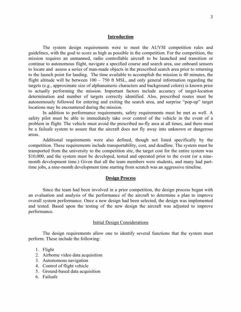
Introduction
The system design requirements were to meet the AUVSI competition rules and guidelines, with the goal to score as high as possible in the competition. For the competition, the mission requires an unmanned, radio controllable aircraft to be launched and transition or continue to autonomous flight, navigate a specified course and search area, use onboard sensors to locate and assess a series of man-made objects in the prescribed search area prior to returning to the launch point for landing. The time available to accomplish the mission is 40 minutes, the flight altitude will be between 100 – 750 ft MSL, and only general information regarding the targets (e.g., approximate size of alphanumeric characters and background colors) is known prior to actually performing the mission. Important factors include accuracy of target-location determination and number of targets correctly identified. Also, prescribed routes must be autonomously followed for entering and exiting the search area, and surprise “pop-up” target locations may be encountered during the mission.
In addition to performance requirements, safety requirements must be met as well. A safety pilot must be able to immediately take over control of the vehicle in the event of a problem in flight. The vehicle must avoid the prescribed no-fly area at all times, and there must be a failsafe system to assure that the aircraft does not fly away into unknown or dangerous areas. Additional requirements were also defined, though not listed specifically by the competition. These requirements include transportability, cost, and deadline. The system must be transported from the university to the competition site, the target cost for the entire system was $10,000, and the system must be developed, tested and operated prior to the event (or a nine-month development time.) Given that all the team members were students, and many had part-time jobs, a nine-month development time starting from scratch was an aggressive timeline.
Design Process
Since the team had been involved in a prior competition, the design process began with an evaluation and analysis of the performance of the aircraft to determine a plan to improve overall system performance. Once a new design had been selected, the design was implemented and tested. Based upon the testing of the new design the aircraft was adjusted to improve performance.
Initial Design Considerations
The design requirements allow one to identify several functions that the system must perform. These include the following:
1. Flight 2. Airborne video data acquisition 3. Autonomous navigation 4. Control of flight vehicle 5. Ground-based data acquisition 6. Failsafe

4
The system must also for the override of manual navigation and control of the flight vehicle. Based on the above functional requirements the basic system concept was modularized into two subsystems: a) target identification and location subsystem, and b) autonomous navigation and control subsystem. And these two subsystems will consist of both airborne and ground-based components. For all airborne components, critical design variables included weight, power, volume, and cost.
Airborne VideoSubsystem
Target ID System
Video Sensor
Target LocatorSystem Airframe
Figure 3: Target Identification and Location Subsystem
The target identification and location subsystem is depicted schematically in Figure 3 below. This depiction is still primarily one of functionality, where each box may consist of hardware and software components, with some airborne and some ground based. It is noted that this subsystem consists of an airframe, a video sensor, a target locator system, and a target identification subsystem.
The autonomous navigation and control subsystem is depicted schematically in Figure 4 below. It is noted that this subsystem consists of the airframe being controlled, a navigation system, and a flight-control system. Again, this depiction is still primarily one of functionality, where each box may consist of hardware and software components, with some airborne and some ground based.
Autonomous Nav. & Control
Subsystem
Flight Control System
Nav. SystemAirframe
Figure 4: Autonomous Navigation and Control Subsystem

5
Given the tight development schedule and limited manpower, to reduce development risk
it was decided that the overall system-design approach would consist of integrating off-the-shelf subsystems, rather than beginning at the circuit-board level, for example. This critical decision was made after much discussion, and a couple false starts. It is also to be noted that this decision drove the development costs.
The overall system design was a combination of customizing circuit board level design and integrating commercially sold subsystems. Described in the following, the designs of the subsystems depicted in Figures 3 and 4 above, including the selection of architectures and components.
Air Vehicle
The use of the Sig Senior plane as opposed last year’s plane, the Sig Kadet was
determined based upon the following reasons including cockpit cavity size, total wing area and overall size. Cockpit cavity size is very important, last year’s the team needed to constantly make sure that nothing physically or RF interference interfered with the servos and the operations of the units inside. This year’s plane has about three times as much room to conduct operations effectively and to allow enough distance for RF interference to dissipate. Secondly, total wing area and overall; this is perhaps the main and most important factor for us choosing the Sig Senior vs. the Sig Kadet. In terms of picture and the camera unit ‘slow is good, dead stop is better’, the found that the Sig Kadet (fully loaded) just flew way too fast for a clear picture. Allowing the airplane’s size and wing area to increase will allow it to have a larger payload weight enabling it to fly slower and a little more stable. These few objectives are the main ideals that didn’t allow us to get the score we had hoped for.
The choice of engine was based upon several factors. First, the two types of power
systems electric and gas. Gas was chosen for two reasons: when compared to the electric was lighter and had the power to fly with the systems payload at Colorado altitude. Next the type of gas engine was decided. The options include: nitro-methane, gasoline and diesel. Diesel was scratched based upon its touchy nature. Then gasoline was scratched based on three reasons: 1) grossly overpowered, 2) unnecessary weight and 3) added electrical noise. Based upon this, it was determined that a nitro-methane engine would be used. Next the size (displacement) and the stroke, 2-stroke or 4-stroke, of the engine was determined. Deciding the size was easy; Sig, the airplane’s manufacture recommended an engine with a displacement between 0.90 in3 and 1.20 in3. A 4-stroke engine is a little more fuel efficient whereas the 2-stroke spits out about 20% unburned fuel into the muffler. So the challenge was to find an engine that had a large thrust to engine weight ratio. The OS FS-120 w/o pump was chosen in the end because it was a good balance of thrust and weight and it was reasonably priced. The OS engine gives the plane the perfect amount of power for flight at an altitude of 6000 ft.

6
Autonomous Navigation and Control
Autopilot
After surveying the availability of off-the-shelf navigation systems for UAVs, the Kestrel system from Procerus [4] was deemed to be a good choice. It nicely meets the requirements for light weight, small volume, and low power; it has the capability of performing all necessary navigation and control functions; and it includes a ground-based system (described below) for operator flight monitoring, as well as command, control, and communication.
The Kestrel autopilot hardware (not including modem, batteries or wiring) weighs only 16.7g and fits in a 1.29in2 volume. Its Inertial Measurement Unit (IMU) includes 3-axis angular rate measurement, 3-axis acceleration measurement, and a 2-axis magnetometer. On-board GPS provides position determination. Absolute and differential pressure sensors provide barometric pressure (altitude) and air speed. Power required is 0.77 Watts from external batteries. A photo of the on-board unit is shown in Figure 6, while a block diagram is shown in Figure 7. Figure 8 shows the autopilot, including wiring and vibration-isolation mountings, installed through the bottom of the fuselage in the flight vehicle. Preserving cg location drove hardware placement.
All axes of the air vehicle are controlled using built-in PID loops. And PID control of the navigation loops is used as well. All these feedback control loops are tuned during flight testing, a process which it enables using the command-and-control software described below.
Figure 6: Kestrel 2.2 Autopilot Interfaced with Aerocomm AC 4490 Modem

7
Figure 7: Autopilot Hardware Block Diagram
Figure 8: Autopilot Installed, With Vibration-Isolation Mountings
Navigation and Control Communications
Navigation and control uplink and downlink communications are accomplished through a pair of Maxstream 9XTEND 900MHz radio modems. Interfacing with a ground-based computer is accomplished using a small communications hub that contains the ground-based modem, antenna, and the serial port connector to interface with a notebook computer [5]. The communications hub also accepts inputs from the RC radio, when the aircraft is under manual control. Manual versus autonomous control is set using one of the channels and switches on the RC radio. The notebook computer, navigation and control communications hub, and RC radio

8
comprise the command and control ground-based hardware. A picture of this hardware system is shown in Figure 9 below.
Ground Control Station
Figure 9: Command and Control Ground Hardware
Vehicle Command and Control
Vehicle command and control is accomplished using a software system executing on the command and control laptop shown in Figure 8. This software [5] is included as part of the Kestrel autopilot system described above. The command and control system includes a graphical user interface (GUI), shown in Figure 10.
The left half of the screen is the vehicle control display, and the layout is similar to a cockpit. Shown are an attitude indicator, along with read-out information such as airspeed and heading. The right half of the screen is the navigation display, consisting of moving-map and read-out information such as GPS-derived location.
Waypoints and other items of interest may be displayed on the moving map. Waypoints, routes, altitudes, and speeds are input via the keyboard prior to the flight, and may be updated in real time. All flight telemetry data can also be saved to a file, for post-flight analysis.

9
Figure 10: Vehicle Command and Control Display
Target Identification and Location The target identification and location subsystem was functionally depicted in the block diagram in Figure 3. Factors driving the design of this subsystem are accuracy, cost, and weight of the airborne components. This subsystem consists of the video payload and downlink, the target identification and location software, the video-processing computer, and the payload operator. Video Payload and Downlink The airborne payload consists of a video camera, video downlink, and associated electronics. This airborne hardware should be small, light, and require low power. The camera should have high resolution, and the times delays from airborne data capture to ground-based display should be a minimum. The selected system is depicted in Figure 11, which provides the technical specifications and photos of the hardware. Also shown is the ground receiver for video downlink to the target ID system described below. The camera is quite small, with a fairly high (480 lines) of resolution.
Finally, placement of the payload was carefully distributed to maintain aircraft cg location.

10
Airborne Camera Specs
Model: KX 141 Type: CCD, color Resolution: 480 lines Sensitivity: 2 lux Video Format: Analog, NTSC Lens: 2.8mm (approx 90degree)
Upgraded Lens: Approx. 30°. Size: Approx 2cm x 3cm Weight: 12.9g Power - Voltage: 5V
600 mW Airborne Transmitter
RF Power Output: 1000mW Type: NTSC Frequency: 2.4GHz, PLL frequency control Antenna: SMA connector, ¼ wave
Weight: 39g (1.4oz) Power - Voltage: 9-12V
Current: 450mA Ground Receiver Antenna: ¼ wave rubber whip, SMA connector 8 channel, selectable Power - Voltage: 8 – 12V
Current: 350mA Figure 11: Video Payload Specifications [6].
Some drawbacks to the system as shown are the problems associated with the use of NTSC video transmission from a moving vehicle. These are: limited bandwidth, and interlacing issues. NTSC video uses an interlacing algorithm that results in sometimes blurred imagery due to the time delay involved in the construction of a video frame. NTSC also limits the maximum resolution possible to 640x480 lines. Moving to a higher resolution would require an upgrade to a different video transmission scheme. One option is a digital scheme that is difficult to achieve in real-time without expensive digital hardware. Since one of the design goals was real time target acquisition, a digital camera coupled with a method of data storage was ruled out as the data in this type of system would only be available post-flight. As a result, the method chosen was the system outlined above, mainly for its real-time capability, low cost, and lower complexity. Target ID and Location System This system was another key component of the overall system, especially since it is so critical to the overall mission objective. Clearly the accuracy of this targeting system will, to a great extent, determine the ultimate success of the mission. The first design decision was whether to perform the target identification automatically, using a pattern-recognition algorithm. But after a fair amount of discussion, and with a looming

11
deadline approaching, it was decided to use the best pattern recognition system known – the human. This decision was driven by two factors, 1) the final targeting results did not need to be provided to the judges until after completion of the flight, and 2) little target information, necessary for algorithm training, was available prior to the flight. The final target ID and Location system developed by the team is depicted in Figure 12 below.
Airborne Video DataAcquisition
Target RecognitionSystem
Telemetry Data
Information Flow
C&C Ground Station
Airborne Position & Attitude Data Acquisition
Navigation And Control System
Video Capture & Display
Acquire Navigation Data Updates
Capture Target Screen Location
Screen Shot & Target LocationRecord
Target Location Determination Algorithm
Target ID And Locator System
Figure 12: Software Block Diagram
This design concept required displaying the ground scene, as viewed by the camera, to
the human, and capturing the ID and location decisions of the human in some fashion. And this has to be accomplished in real time, with minimal delay. A second laptop PC was used to display the ground scene to the human operator, and this laptop constitutes a major part of the ground-based payload control station. The ground-scene is displayed in real time (save for digital processing delay). Capturing the human’s decisions was performed by the targeting software developed by the team.
This targeting software is hosted on the payload-control computer, and the software performs all the functions shown in the red dashed box in Figure 12. The targeting software continuously acquires position and attitude information from the navigation and control system,

12
(the blue dashed box in the figure), plus continuously receives and displays the ground scene obtained from the airborne video payload. When the human operator sees a target on the display, the operator places the cursor on the target and clicks the mouse. That process continues until the team determines that no more targets need be identified, or the time limit is reached.
Every time the mouse is clicked, the targeting software performs the remaining tasks. At “click time, the ground scene being displayed is captured, along with the mouse’s cursor location on the laptop screen. The navigation data (position and attitude) corresponding to click time” is also captured. From the navigation data, the inertial direction of the airborne-camera’s bore-sight vector is determined. Knowing this direction, aircraft altitude, and the position of the mouse’s cursor on the display screen, the inertial position of the target may be derived. The saved screen shot and the derived target position are then stored for post-flight analysis. The system as designed contains many potential sources of error. The main source of error results from errors in GPS location errors. Due to various reasons, the GPS data received from the GPS constellation is inaccurate. Errors are also present due to the inability of GPS filters to handle rapidly varying location data, offset camera angles where the camera is assumed to be oriented such that it is normal to the plane of flight, and inaccuracy in the camera field of view measurements both of which are used in the software to calculate target locations.
Failsafe
The failsafe was designed from a circuit level design with the purpose of safety. The failsafe when activated will put the plane into a downward spiral, as described by competition design rules, in order to prevent it from flying into unknown or no-fly areas. The failsafe has both incoming power from the varying batteries onboard the aircraft as well as a 5V power source. The failsafe is composed of two parts, the power and switching board and the control. The circuit board is displayed in Figure 13 and the power and switching board schematic is displayed in Figure 14.
Figure 14: Switching and power board for failsafe system.

13
Figure 14: Switching and power board schematic for failsafe system. The second portion of the failsafe is the controller which is based upon the desired modes of operation displayed in Table 1.
Scenario
Kestrel Signal Lost
Kestrel Timeout
ManualControlPWM
RC Signal Loss
Scenario Description
0 x 1 x 1 μC sets to slow spiral crash 1 1 0 x 1 Have Kestrel fly home 2 0 0 x 1 Give control to Kestrel 3 x x 1 0 Give control to RC receiver 4 x 1 0 0 μC sets to slow spiral crash 5 1 0 0 0 Have Kestrel fly home 6 0 0 0 0 Give control to Kestrel
Table 1 – Basic Failsafe Scenarios
Since the failsafe can support many modes of operation, the modes need to be selected. The mode will be determined by the state of various inputs. Based upon these possible scenarios, the controller was designed and programmed. In Figure 15 the schematic for the control board is displayed. The controller comprises of a microprocessor and the electrical components for the corresponding inputs and outputs.

14
Figure 15: Controller board schematic for failsafe system.
With the corresponding programming based upon the modes of operations, the failsafe
performs as expected. (No pictures of the controller board were available at the time of this paper).
Onboard Power System
Similar to the targeting software, the onboard power system was also developed by the
team. The onboard power supply system is shown in Figure 13. Power is provided by four batteries: two Lithium Polymer (LiPo) batteries for the Kestrel and video payload, and two Nickel Cadmium (NiCd) batteries for the fail safe, R/C radio and servos.

15
9.6V 1.5AH NiMH Main Servo
Battery
4.8V 1.5AH NiMH
Fail Safe and Aux. Battery
11.1V 2.3AH LiPo
Kestrel Battery
11.1V 2.3AH LiPo Video Battery
Kestrel
Fail Safe
R/C Radio
Servos
Power Regulator
5V
Video Camera
Video Transmitter
GPS
Onboard UAV Power Supply System
Figure 13: Onboard Electrical Power System
Lithium polymer batteries were selected for their high ampere-hour: weight ratio and their ability to accept a new charge after many discharge cycles. No other commercially available battery can provide a high level of performance than the lithium-polymer battery. The

16
only negative of the lithium-polymer batteries was the need for current limiting and voltage monitoring circuitry to prevent catastrophic battery failure and bodily injury. At 2.3AH the two main 11.1V LiPo batteries are the largest. The Kestrel LiPo powers the autopilot, the GPS receiver unit, and the navigation-and-control up and downlink modem. The connection is routed through the autopilot hardware, and multiplexed with the servo controls. The other LiPo is used to power the payload video and video downlink electronics. A 4.8V NiCd is used for the control servos but does not connect directly to the servos.
Summary and Conclusions
The ultimate focus of the team was to compete in the international student competition sponsored by the Association for Unmanned Vehicle Systems International (AUVSI) and successfully complete the mission described in the competition guidelines. Including the image capturing of the targets in a timely. accurate and safe manner. The air vehicle was design using both commercially available components as well as custom made parts.
NSUAV of UCCS raised all funding required for the project, developed the video-surveillance UAV system in a nine month timeline, while meeting the cost limit of $10,000.

17
References
1. AUVSI Aerial Robotic Competition. www.bowheadsupport.com/paxweb/seafarers/default.htm Accessed November 13 2006.
2. Ulrich and Eppinger, Product Design and Development McGraw-Hill (2000).
3. SIG Kadet LT 40 Data. http://www.rcuniverse.com/product_guide/kitprofile.cfm?kit_id=10
Accessed March 22, 2007 4. Kestrel Autopilot v2.2 Datasheet, Procerus Technologies, www.procerusuav.com
Accessed March 24, 2007
5. Virtual Cockpit v2.2 Datasheet, Procerus Technologies, www.procerusuav.com Accessed March 24, 2007
6. Digital Camera & Xmitter, Black Widow AV, www.blackwidowav.com/ Accessed April 4, 2007