2004 IMPREZA SERVICE MANUAL QUICK - ken-
41
FUJI HEAVY INDUSTRIES LTD. G1870GE3 2004 IMPREZA SERVICE MANUAL QUICK REFERENCE INDEX ENGINE SECTION 2 This service manual has been prepared to provide SUBARU service personnel with the necessary information and data for the correct maintenance and repair of SUBARU vehicles. This manual includes the procedures for maintenance, disassembling, reas- sembling, inspection and adjustment of components and diagnostics for guid- ance of experienced mechanics. Please peruse and utilize this manual fully to ensure complete repair work for satisfying our customers by keeping their vehicle in optimum condition. When replacement of parts during repair work is needed, be sure to use SUBARU genuine parts. All information, illustration and specifi- cations contained in this manual are based on the latest product information available at the time of publication approval. FUEL INJECTION (FUEL SYSTEMS) FU(H4DOTC) EMISSION CONTROL (AUX. EMISSION CONTROL DEVICES) EC(H4DOTC) INTAKE (INDUCTION) IN(H4DOTC) MECHANICAL ME(H4DOTC) EXHAUST EX(H4DOTC) COOLING CO(H4DOTC) LUBRICATION LU(H4DOTC) SPEED CONTROL SYSTEMS SP(H4DOTC) IGNITION IG(H4DOTC) STARTING/CHARGING SYSTEMS SC(H4DOTC) ENGINE (DIAGNOSTICS) EN(H4DOTC)(diag)
Transcript of 2004 IMPREZA SERVICE MANUAL QUICK - ken-
2004 IMPREZA SERVICE MANUAL QUICK REFERENCE INDEX
ENGINE SECTION 2
This service manual has been preparedto provide SUBARU service personnelwith the necessary information and datafor the correct maintenance and repairof SUBARU vehicles.This manual includes the proceduresfor maintenance, disassembling, reas-sembling, inspection and adjustment ofcomponents and diagnostics for guid-ance of experienced mechanics.Please peruse and utilize this manualfully to ensure complete repair work forsatisfying our customers by keepingtheir vehicle in optimum condition.When replacement of parts duringrepair work is needed, be sure to useSUBARU genuine parts.
All information, illustration and specifi-cations contained in this manual arebased on the latest product informationavailable at the time of publicationapproval.
FUJI HEAVY INDUSTRIES LTD.
FUEL INJECTION (FUEL SYSTEMS) FU(H4DOTC)
EMISSION CONTROL (AUX. EMISSION CONTROL DEVICES)
EC(H4DOTC)
INTAKE (INDUCTION) IN(H4DOTC)
MECHANICAL ME(H4DOTC)
EXHAUST EX(H4DOTC)
COOLING CO(H4DOTC)
LUBRICATION LU(H4DOTC)
SPEED CONTROL SYSTEMS SP(H4DOTC)
IGNITION IG(H4DOTC)
STARTING/CHARGING SYSTEMS SC(H4DOTC)
ENGINE (DIAGNOSTICS) EN(H4DOTC)(diag)
G1870GE3
FUEL INJECTION (FUEL SYSTEMS)
FU(H4DOTC)
Page1. General Description ....................................................................................22. Throttle Body.............................................................................................133. Intake Manifold..........................................................................................144. Engine Coolant Temperature Sensor........................................................285. Crankshaft Position Sensor.......................................................................296. Camshaft Position Sensor.........................................................................307. AVCS Camshaft Position Sensor..............................................................318. Knock Sensor............................................................................................329. Throttle Position Sensor............................................................................33
10. Mass Air Flow and Intake Air Temperature Sensor ..................................3411. Manifold Absolute Pressure Sensor..........................................................3512. Idle Air Control Solenoid Valve .................................................................3613. Fuel Injector ..............................................................................................3714. Tumble Generator Valve Assembly ..........................................................4115. Tumble Generator Valve Actuator.............................................................4216. Wastegate Control Solenoid Valve ...........................................................4317. Front Oxygen (A/F) Sensor .......................................................................4418. Rear Oxygen Sensor.................................................................................4619. Exhaust Temperature Sensor ...................................................................4820. Engine Control Module (ECM) ..................................................................4921. Main Relay ................................................................................................5022. Fuel Pump Relay.......................................................................................5123. Fuel Pump Control Unit.............................................................................5224. Fuel ...........................................................................................................5325. Fuel Tank ..................................................................................................5426. Fuel Filler Pipe ..........................................................................................5727. Fuel Pump.................................................................................................6128. Fuel Level Sensor .....................................................................................6329. Fuel Sub Level Sensor..............................................................................6430. Fuel Filter ..................................................................................................6631. Fuel Cut Valve...........................................................................................6732. Fuel Damper Valve ...................................................................................6833. Fuel Delivery, Return and Evaporation Lines............................................6934. Fuel System Trouble in General ...............................................................72
FUEL INJECTION (FUEL SYSTEMS)General Description
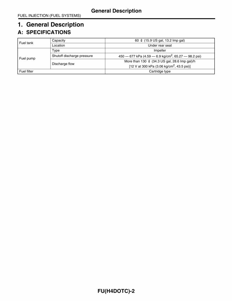
1. General DescriptionA: SPECIFICATIONS
Fuel tankCapacity 60 2 (15.9 US gal, 13.2 Imp gal)
Location Under rear seat
Fuel pump
Type Impeller
Shutoff discharge pressure 450 — 677 kPa (4.59 — 6.9 kg/cm2, 65.27 — 98.2 psi)
Discharge flowMore than 130 2 (34.3 US gal, 28.6 Imp gal)/h
[12 V at 300 kPa (3.06 kg/cm2, 43.5 psi)]
Fuel filter Cartridge type
FU(H4DOTC)-2
FUEL INJECTION (FUEL SYSTEMS)General Description
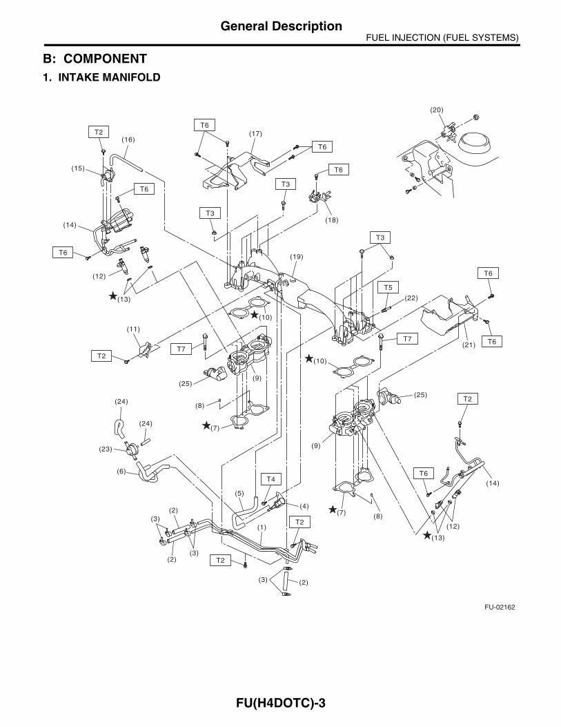
B: COMPONENT1. INTAKE MANIFOLD
FU-02162
(16)
(15)
(11)
T6
T2
T6
T2
T2
(24)
(24)
(23)
(6)
(2)
(2)
(3)
(3)
T7
(1)
(5)
(2)(3)
(4)
(14)
(12)
(13)
(21)
(22)
T2
T6
T5
T3
T6
T6
T3
T6
T7 T6
T6T4
(8)(7)
(18)
(20)
(17)
(19)
(7)
(10)
(10)
(12)
(14)
(13)
(8)
(9)
T3
(9)
T2
(25)
(25)
FU(H4DOTC)-3
FUEL INJECTION (FUEL SYSTEMS)General Description
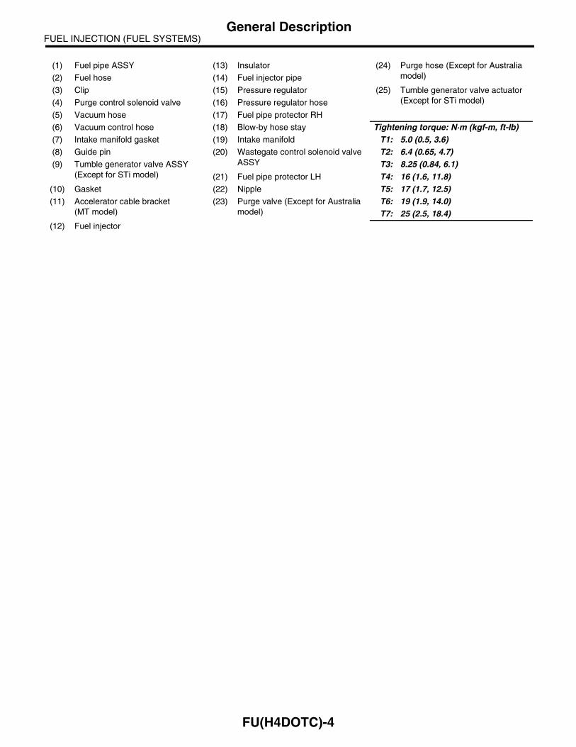
(1) Fuel pipe ASSY (13) Insulator (24) Purge hose (Except for Australia model)(2) Fuel hose (14) Fuel injector pipe
(3) Clip (15) Pressure regulator (25) Tumble generator valve actuator (Except for STi model)(4) Purge control solenoid valve (16) Pressure regulator hose
(5) Vacuum hose (17) Fuel pipe protector RH
(6) Vacuum control hose (18) Blow-by hose stay Tightening torque: N·m (kgf-m, ft-lb)(7) Intake manifold gasket (19) Intake manifold T1: 5.0 (0.5, 3.6)(8) Guide pin (20) Wastegate control solenoid valve
ASSYT2: 6.4 (0.65, 4.7)
(9) Tumble generator valve ASSY (Except for STi model)
T3: 8.25 (0.84, 6.1)(21) Fuel pipe protector LH T4: 16 (1.6, 11.8)
(10) Gasket (22) Nipple T5: 17 (1.7, 12.5)(11) Accelerator cable bracket
(MT model)(23) Purge valve (Except for Australia
model)T6: 19 (1.9, 14.0)T7: 25 (2.5, 18.4)
(12) Fuel injector
FU(H4DOTC)-4

FUEL INJECTION (FUEL SYSTEMS)General Description
2. AIR INTAKE SYSTEM
(1) Gasket (5) Manifold absolute pressure sensor Tightening torque: N·m (kgf-m, ft-lb)(2) Throttle position sensor (6) Gasket T1: 1.6 (0.16, 1.2)(3) Idle air control solenoid valve (7) O-ring T2: 2.8 (0.29, 2.1)(4) Throttle body T3: 22 (2.2, 16.2)
FU-00002
(1)
(5)
(7)
(2)
(4)
T1
T1
T3
(3)
(6)
T2
FU(H4DOTC)-5

FUEL INJECTION (FUEL SYSTEMS)General Description
3. CRANKSHAFT POSITION, CAMSHAFT POSITION AND KNOCK SENSORS
(1) Crankshaft position sensor (4) AVCS camshaft position sensor (STi model and Australia model)
Tightening torque: N·m (kgf-m, ft-lb)(2) Knock sensor T1: 6.4 (0.65, 4.7)(3) Camshaft position sensor T2: 24 (2.4, 17.4)
FU-00003
T1(4)
T1
T1T2
T1
(4)(2)
(3)
(1)
FU(H4DOTC)-6
FUEL INJECTION (FUEL SYSTEMS)General Description
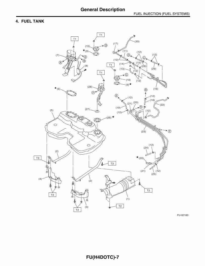
4. FUEL TANK
FU-02183
T1
T1
T3
T2
T2
T2
T2
T3
(7)
(6)
(8)
(9)
(10)
(10)
(9)
(19)
(18)
(22)
(12) (12)
(12)
(23)
(12)
(12)
(24)
(25)
(12)
(21) (20)
(1)
(2)
(3)
(4)
(2)
(5)
AB
(28)
(29)
(16)
F
F
A
E
T1
T1
DC
D
C
(20)
(12)(12)
(12)
(12)
(12)
(29)(13)
(14)
(11)
(17)(30)
(27)
(26)
(15)
E
B
(21)
FU(H4DOTC)-7
FUEL INJECTION (FUEL SYSTEMS)General Description
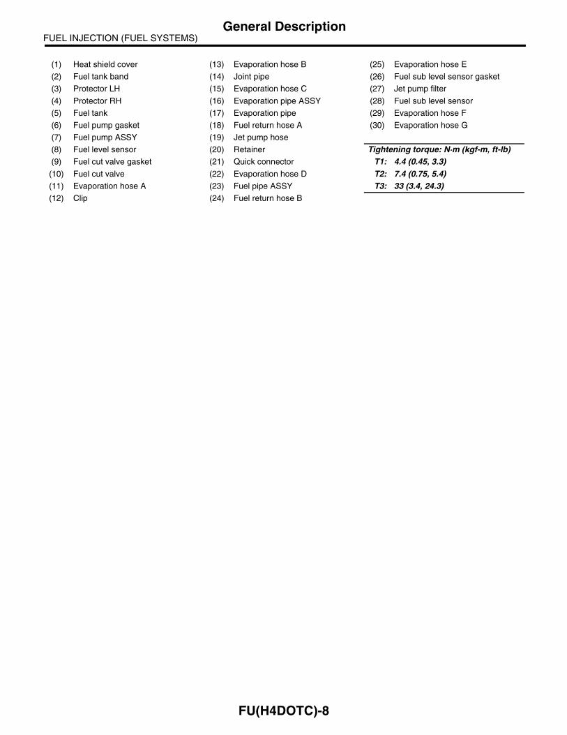
(1) Heat shield cover (13) Evaporation hose B (25) Evaporation hose E
(2) Fuel tank band (14) Joint pipe (26) Fuel sub level sensor gasket
(3) Protector LH (15) Evaporation hose C (27) Jet pump filter
(4) Protector RH (16) Evaporation pipe ASSY (28) Fuel sub level sensor
(5) Fuel tank (17) Evaporation pipe (29) Evaporation hose F
(6) Fuel pump gasket (18) Fuel return hose A (30) Evaporation hose G
(7) Fuel pump ASSY (19) Jet pump hose
(8) Fuel level sensor (20) Retainer Tightening torque: N·m (kgf-m, ft-lb)(9) Fuel cut valve gasket (21) Quick connector T1: 4.4 (0.45, 3.3)
(10) Fuel cut valve (22) Evaporation hose D T2: 7.4 (0.75, 5.4)(11) Evaporation hose A (23) Fuel pipe ASSY T3: 33 (3.4, 24.3)(12) Clip (24) Fuel return hose B
FU(H4DOTC)-8
FUEL INJECTION (FUEL SYSTEMS)General Description
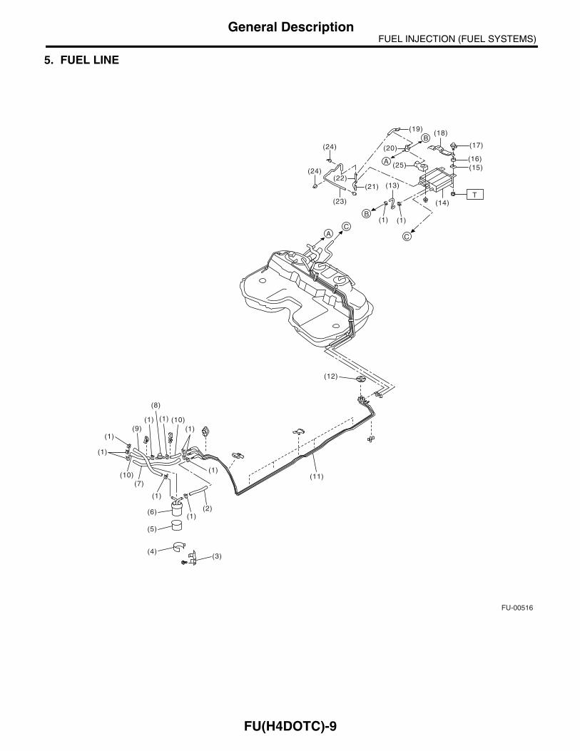
5. FUEL LINE
FU-00516
(12)
(11)(1)
(1)
(1)
(7)
(1)
(1)(9)
(10)
(10)
(1)
(6)
(5)
(4)(3)
(2)
(1) (1)
(8)
(24)
(24)
(18)
(23)
(13)
(14)
(1) (1)
(21)
(20)
(25)
(22)
(19)
(17)
(16)(15)
C
B
B
A
CA
T
FU(H4DOTC)-9

FUEL INJECTION (FUEL SYSTEMS)General Description
(1) Clip (11) Fuel pipe ASSY (21) Two-way valve drain hose A
(2) Fuel delivery hose A (12) Grommet (22) Connector
(3) Fuel filter bracket (13) Canister hose A (23) Two-way valve drain hose B
(4) Fuel filter holder (14) Canister (24) Clamp
(5) Fuel filter cup (15) Canister bracket plate (25) Front canister bracket
(6) Fuel filter (16) Cushion
(7) Evaporation hose (17) Canister bracket spacer Tightening torque: N·m (kgf-m, ft-lb)(8) Fuel damper (18) Rear canister bracket T: 23 (2.3, 17.0)(9) Fuel delivery hose B (19) Two-way valve return hose
(10) Fuel return hose (20) Two-way valve
FU(H4DOTC)-10
FUEL INJECTION (FUEL SYSTEMS)General Description
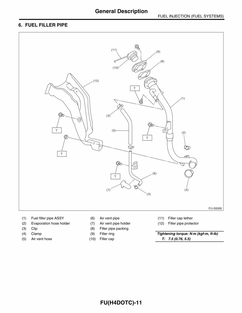
6. FUEL FILLER PIPE
(1) Fuel filler pipe ASSY (6) Air vent pipe (11) Filler cap tether
(2) Evaporation hose holder (7) Air vent pipe holder (12) Filler pipe protector
(3) Clip (8) Filler pipe packing
(4) Clamp (9) Filler ring Tightening torque: N·m (kgf-m, ft-lb)(5) Air vent hose (10) Filler cap T: 7.5 (0.76, 5.5)
FU-00006
(4)
(2)
(8)
(1)
(12)
(11)
(6)
(7)
(9)
(10)
(5)
(3)
(3)
T
T
T
T
T
FU(H4DOTC)-11
FUEL INJECTION (FUEL SYSTEMS)General Description
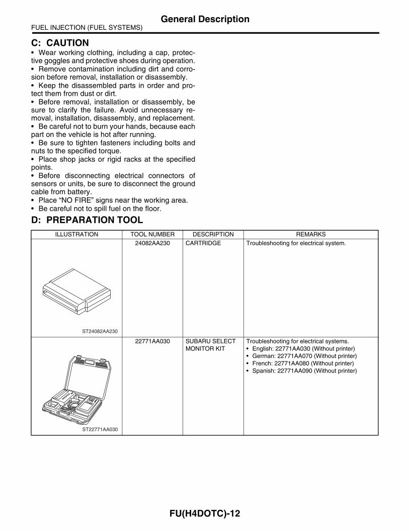
C: CAUTION• Wear working clothing, including a cap, protec-tive goggles and protective shoes during operation.• Remove contamination including dirt and corro-sion before removal, installation or disassembly.• Keep the disassembled parts in order and pro-tect them from dust or dirt.• Before removal, installation or disassembly, besure to clarify the failure. Avoid unnecessary re-moval, installation, disassembly, and replacement.• Be careful not to burn your hands, because eachpart on the vehicle is hot after running.• Be sure to tighten fasteners including bolts andnuts to the specified torque.• Place shop jacks or rigid racks at the specifiedpoints.• Before disconnecting electrical connectors ofsensors or units, be sure to disconnect the groundcable from battery.• Place “NO FIRE” signs near the working area.• Be careful not to spill fuel on the floor.
D: PREPARATION TOOLILLUSTRATION TOOL NUMBER DESCRIPTION REMARKS
24082AA230 CARTRIDGE Troubleshooting for electrical system.
22771AA030 SUBARU SELECT MONITOR KIT
Troubleshooting for electrical systems.• English: 22771AA030 (Without printer)• German: 22771AA070 (Without printer)• French: 22771AA080 (Without printer)• Spanish: 22771AA090 (Without printer)
ST24082AA230
ST22771AA030
FU(H4DOTC)-12

FUEL INJECTION (FUEL SYSTEMS)Throttle Body
2. Throttle BodyA: REMOVAL1) Disconnect the ground cable from battery.
2) Remove the intercooler. <Ref. to IN(H4DOTC)-10, REMOVAL, Intercooler.>3) Disconnect the connector from the throttle posi-tion sensor (A) and idle air control solenoid valve(B) and manifold absolute pressure sensor (C).
4) Disconnect the accelerator cable.
5) Disconnect the engine coolant hoses from throt-tle body.
6) Remove the bolts which secure the throttle bodyto intake manifold.
B: INSTALLATION1) Install in the reverse order of removal.
NOTE:Always use a new gasket.
Tightening torque:22 N·m (2.2 kgf-m, 16.2 ft-lb)
2) Adjust the accelerator cable play. <Ref. toSP(H4SO)-9, INSTALLATION, Accelerator ControlCable.>
FU-00009
(A)
(B)
(C)
FU-00010
FU-00011
FU-00012
FU-00013
FU(H4DOTC)-13

FUEL INJECTION (FUEL SYSTEMS)Intake Manifold
3. Intake ManifoldA: REMOVAL1) Release the fuel pressure. <Ref. toFU(H4DOTC)-53, RELEASING OF FUEL PRES-SURE, OPERATION, Fuel.>2) Open the fuel filler flap lid and remove the fuelfiller cap.3) Disconnect the ground cable from battery.
4) Lift-up the vehicle.5) Remove the under cover.6) Drain the coolant about 3.0 2 (3.2 US qt, 2.6Imp qt).
7) Remove the air cleaner upper cover and air in-take boot. <Ref. to IN(H4DOTC)-7, REMOVAL, AirCleaner.>8) Remove the air cleaner element.9) Remove the intercooler. <Ref. to IN(H4DOTC)-10, REMOVAL, Intercooler.>10) Disconnect the accelerator cable.
11) Remove the coolant filler tank. <Ref. toCO(H4DOTC)-33, REMOVAL, Coolant FillerTank.>12) Remove the power steering pump.
(1) Remove the front side V-belt. <Ref. to ME(H4DOTC)-54, REMOVAL, V-belt.>(2) Disconnect the power steering switch con-nector.
(3) Remove the bolts which secure the powersteering pipe brackets to intake manifold.
NOTE:Do not disconnect the power steering hose.
(4) Remove the bolts which secure the powersteering pump bracket.
FU-00009
FU-00016
FU-00011
FU-00017
FU-00018
FU-00019
FU(H4DOTC)-14
FUEL INJECTION (FUEL SYSTEMS)Intake Manifold
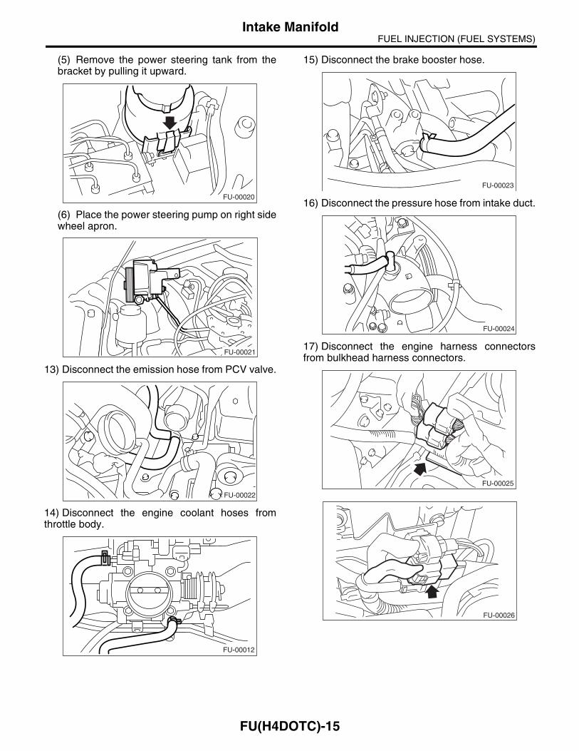
(5) Remove the power steering tank from thebracket by pulling it upward.
(6) Place the power steering pump on right sidewheel apron.
13) Disconnect the emission hose from PCV valve.
14) Disconnect the engine coolant hoses fromthrottle body.
15) Disconnect the brake booster hose.
16) Disconnect the pressure hose from intake duct.
17) Disconnect the engine harness connectorsfrom bulkhead harness connectors.
FU-00020
FU-00021
FU-00022
FU-00012
FU-00023
FU-00024
FU-00025
FU-00026
FU(H4DOTC)-15
FUEL INJECTION (FUEL SYSTEMS)Intake Manifold
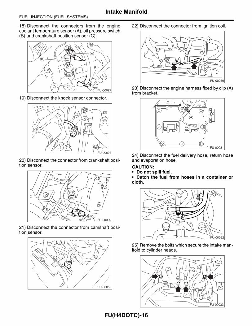
18) Disconnect the connectors from the enginecoolant temperature sensor (A), oil pressure switch(B) and crankshaft position sensor (C).
19) Disconnect the knock sensor connector.
20) Disconnect the connector from crankshaft posi-tion sensor.
21) Disconnect the connector from camshaft posi-tion sensor.
22) Disconnect the connector from ignition coil.
23) Disconnect the engine harness fixed by clip (A)from bracket.
24) Disconnect the fuel delivery hose, return hoseand evaporation hose.
CAUTION:• Do not spill fuel.• Catch the fuel from hoses in a container orcloth.
25) Remove the bolts which secure the intake man-ifold to cylinder heads.
(A)
(B)
(C)
FU-00027
FU-00028
FU-00029
FU-00059
FU-00030
FU-00031
(A)
FU-00032
FU-00033
FU(H4DOTC)-16
FUEL INJECTION (FUEL SYSTEMS)Intake Manifold
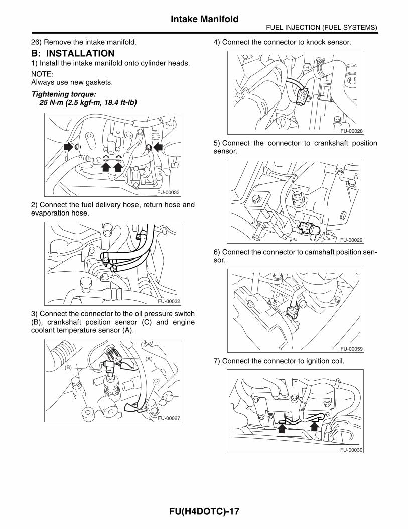
26) Remove the intake manifold.
B: INSTALLATION1) Install the intake manifold onto cylinder heads.
NOTE:Always use new gaskets.
Tightening torque:25 N·m (2.5 kgf-m, 18.4 ft-lb)
2) Connect the fuel delivery hose, return hose andevaporation hose.
3) Connect the connector to the oil pressure switch(B), crankshaft position sensor (C) and enginecoolant temperature sensor (A).
4) Connect the connector to knock sensor.
5) Connect the connector to crankshaft positionsensor.
6) Connect the connector to camshaft position sen-sor.
7) Connect the connector to ignition coil.
FU-00033
FU-00032
(A)
(B)
(C)
FU-00027
FU-00028
FU-00029
FU-00059
FU-00030
FU(H4DOTC)-17

FUEL INJECTION (FUEL SYSTEMS)Intake Manifold
8) Connect the engine harness with clip (A) to thebracket.
9) Connect the engine harness connector to bulk-head harness connectors.
10) Connect the brake booster vacuum hose.
11) Connect the engine coolant hoses to throttlebody.
12) Connect the emission hose to PCV valve.
13) Connect the pressure hose to intake duct.
14) Install the power steering pump.(1) Install the power steering tank on bracket.
FU-00031
(A)
FU-00025
FU-00026
FU-00023
FU-00012
FU-00022
FU-00024
FU-00020
FU(H4DOTC)-18
FUEL INJECTION (FUEL SYSTEMS)Intake Manifold
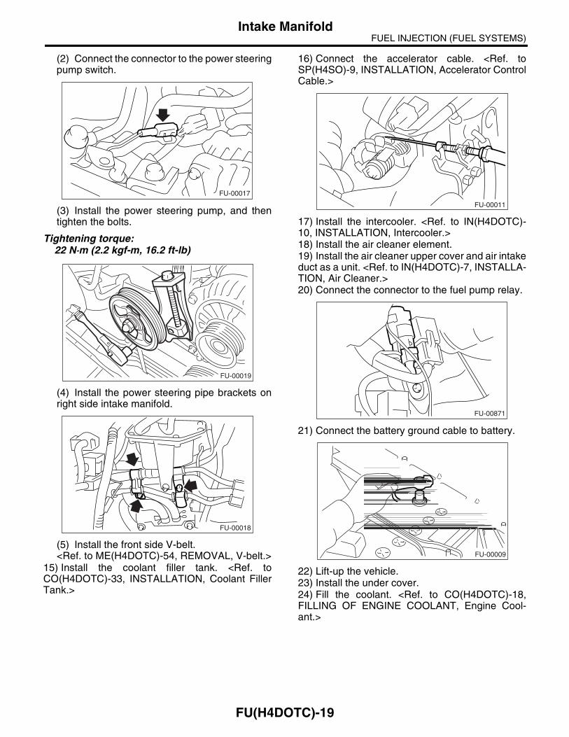
(2) Connect the connector to the power steeringpump switch.
(3) Install the power steering pump, and thentighten the bolts.
Tightening torque:22 N·m (2.2 kgf-m, 16.2 ft-lb)
(4) Install the power steering pipe brackets onright side intake manifold.
(5) Install the front side V-belt. <Ref. to ME(H4DOTC)-54, REMOVAL, V-belt.>
15) Install the coolant filler tank. <Ref. toCO(H4DOTC)-33, INSTALLATION, Coolant FillerTank.>
16) Connect the accelerator cable. <Ref. toSP(H4SO)-9, INSTALLATION, Accelerator ControlCable.>
17) Install the intercooler. <Ref. to IN(H4DOTC)-10, INSTALLATION, Intercooler.>18) Install the air cleaner element.19) Install the air cleaner upper cover and air intakeduct as a unit. <Ref. to IN(H4DOTC)-7, INSTALLA-TION, Air Cleaner.>20) Connect the connector to the fuel pump relay.
21) Connect the battery ground cable to battery.
22) Lift-up the vehicle.23) Install the under cover.24) Fill the coolant. <Ref. to CO(H4DOTC)-18,FILLING OF ENGINE COOLANT, Engine Cool-ant.>
FU-00017
FU-00019
FU-00018
FU-00011
FU-00871
FU-00009
FU(H4DOTC)-19
FUEL INJECTION (FUEL SYSTEMS)Intake Manifold
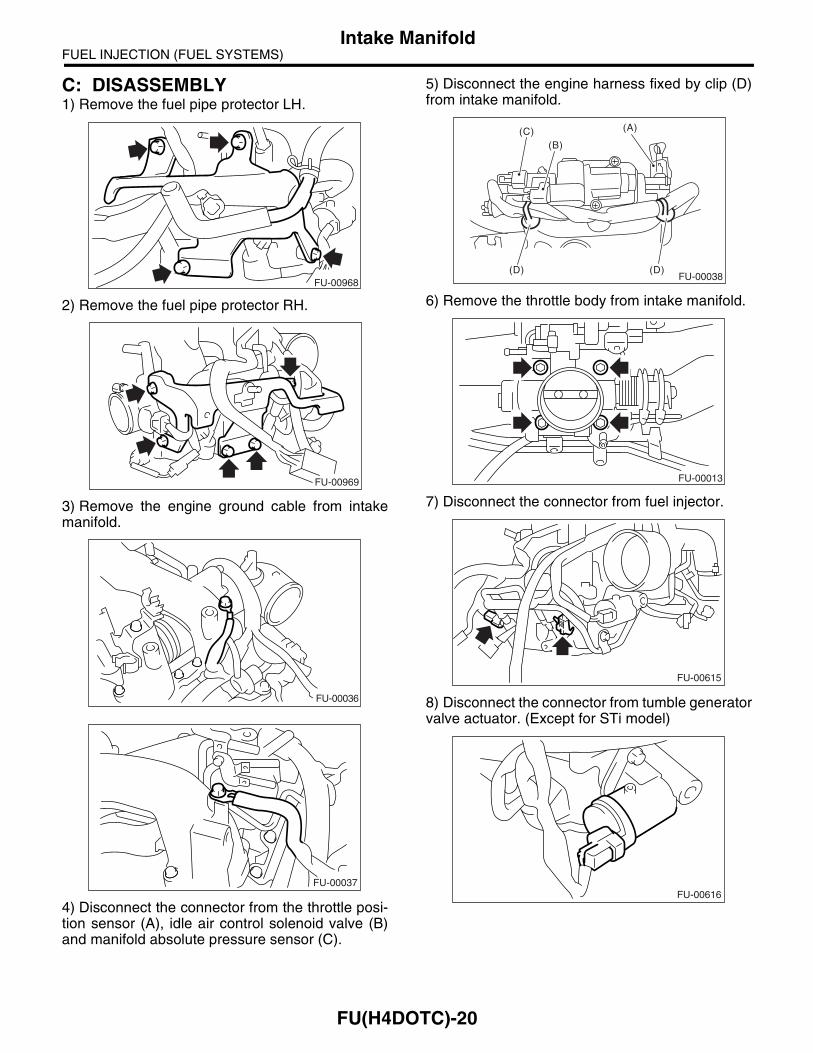
C: DISASSEMBLY1) Remove the fuel pipe protector LH.
2) Remove the fuel pipe protector RH.
3) Remove the engine ground cable from intakemanifold.
4) Disconnect the connector from the throttle posi-tion sensor (A), idle air control solenoid valve (B)and manifold absolute pressure sensor (C).
5) Disconnect the engine harness fixed by clip (D)from intake manifold.
6) Remove the throttle body from intake manifold.
7) Disconnect the connector from fuel injector.
8) Disconnect the connector from tumble generatorvalve actuator. (Except for STi model)
FU-00968
FU-00969
FU-00036
FU-00037
FU-00038
(A)
(B)(C)
(D) (D)
FU-00013
FU-00615
FU-00616
FU(H4DOTC)-20
FUEL INJECTION (FUEL SYSTEMS)Intake Manifold
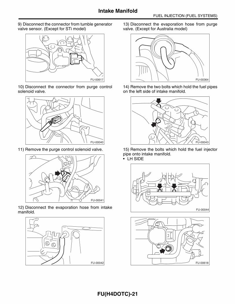
9) Disconnect the connector from tumble generatorvalve sensor. (Except for STi model)
10) Disconnect the connector from purge controlsolenoid valve.
11) Remove the purge control solenoid valve.
12) Disconnect the evaporation hose from intakemanifold.
13) Disconnect the evaporation hose from purgevalve. (Except for Australia model)
14) Remove the two bolts which hold the fuel pipeson the left side of intake manifold.
15) Remove the bolts which hold the fuel injectorpipe onto intake manifold.• LH SIDE
FU-00617
FU-00040
FU-00041
FU-00042
FU-00364
FU-00043
FU-00044
FU-00618
FU(H4DOTC)-21
FUEL INJECTION (FUEL SYSTEMS)Intake Manifold
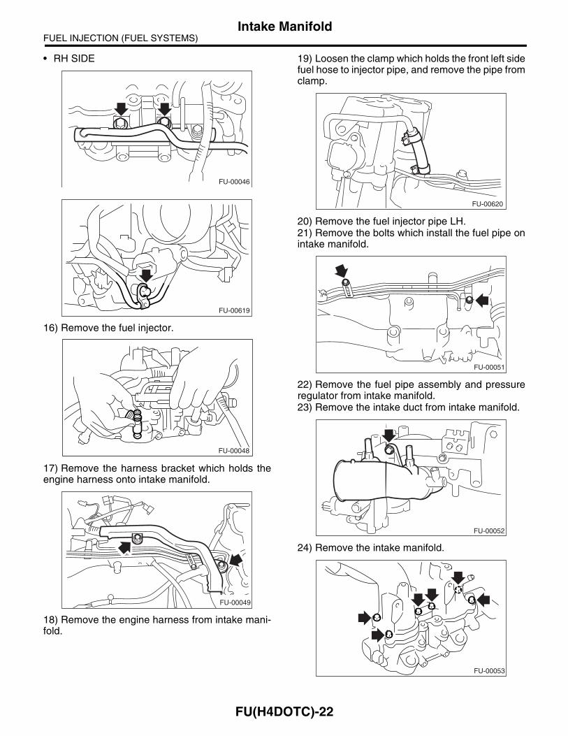
• RH SIDE
16) Remove the fuel injector.
17) Remove the harness bracket which holds theengine harness onto intake manifold.
18) Remove the engine harness from intake mani-fold.
19) Loosen the clamp which holds the front left sidefuel hose to injector pipe, and remove the pipe fromclamp.
20) Remove the fuel injector pipe LH.21) Remove the bolts which install the fuel pipe onintake manifold.
22) Remove the fuel pipe assembly and pressureregulator from intake manifold.23) Remove the intake duct from intake manifold.
24) Remove the intake manifold.
FU-00046
FU-00619
FU-00048
FU-00049
FU-00620
FU-00051
FU-00052
FU-00053
FU(H4DOTC)-22

FUEL INJECTION (FUEL SYSTEMS)Intake Manifold
D: ASSEMBLYNOTE:Replace the gasket with a new one.1) Install the intake manifold.
Tightening torque:8.25 N·m (0.84 kgf-m, 6.1 ft-lb)
2) Install the air intake duct to intake manifold.
Tightening torque:19 N·m (1.9 kgf-m, 14.0 ft-lb)
3) Install the fuel pipe assembly and pressure reg-ulator to intake manifold.
Tightening torque:4.9 N·m (0.5 kgf-m, 3.6 ft-lb)
4) Install the fuel injector pipe LH.
5) Connect the left side fuel hose to injector pipe,and tighten the clamp screw.
6) Install the engine harness to intake manifold.7) Install the harness bracket which holds the en-gine harness onto intake manifold.
Tightening torque:19 N·m (1.9 kgf-m, 14.0 ft-lb)
8) Install the fuel injector.
FU-00053
FU-00052
FU-00051
FU-00620
FU-00049
FU-00048
FU(H4DOTC)-23
FUEL INJECTION (FUEL SYSTEMS)Intake Manifold
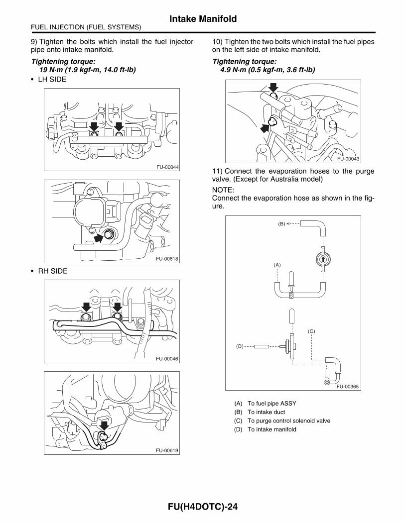
9) Tighten the bolts which install the fuel injectorpipe onto intake manifold.
Tightening torque:19 N·m (1.9 kgf-m, 14.0 ft-lb)
• LH SIDE
• RH SIDE
10) Tighten the two bolts which install the fuel pipeson the left side of intake manifold.
Tightening torque:4.9 N·m (0.5 kgf-m, 3.6 ft-lb)
11) Connect the evaporation hoses to the purgevalve. (Except for Australia model)
NOTE:Connect the evaporation hose as shown in the fig-ure.
FU-00044
FU-00618
FU-00046
FU-00619
(A) To fuel pipe ASSY
(B) To intake duct
(C) To purge control solenoid valve
(D) To intake manifold
FU-00043
FU-00365
(A)
(B)
(C)
(D)
FU(H4DOTC)-24

FUEL INJECTION (FUEL SYSTEMS)Intake Manifold
12) Connect the evaporation hose to intake mani-fold.
13) Install the purge control solenoid valve.
Tightening torque:16 N·m (1.6 kgf-m, 11.8 ft-lb)
14) Connect the hoses to the purge control sole-noid valve.
NOTE:Connect the evaporation hose as shown in the fig-ure.
15) Connect the connector to the purge control so-lenoid valve.
16) Connect the connector to the tumble generatorvalve sensor. (Except for STi model)
17) Connect the connector to the tumble generatorvalve actuator. (Except for STi model)
18) Connect the connector to fuel injector.
(A) To intake manifold
(B) To fuel pipe (Australia model)
To purge valve (Except for Australia model)
FU-00042
FU-00041
(A)
(B) FU-00054
FU-00040
FU-00617
FU-00616
FU-00615
FU(H4DOTC)-25
FUEL INJECTION (FUEL SYSTEMS)Intake Manifold
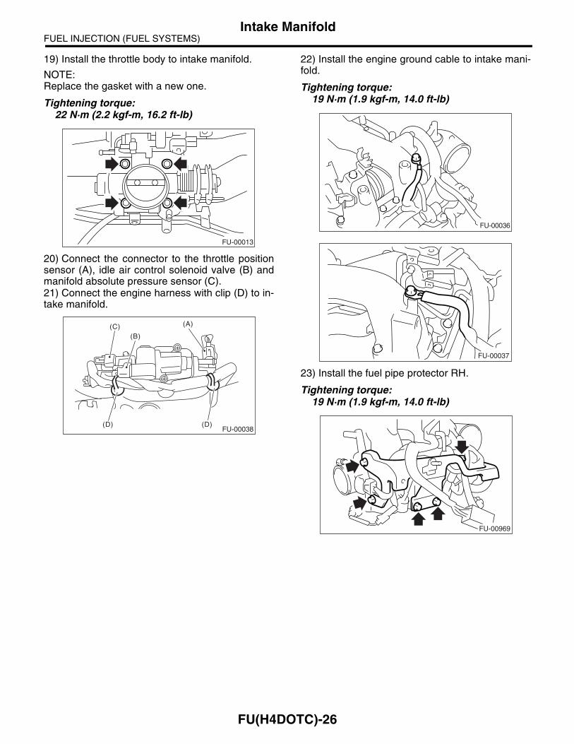
19) Install the throttle body to intake manifold.
NOTE:Replace the gasket with a new one.
Tightening torque:22 N·m (2.2 kgf-m, 16.2 ft-lb)
20) Connect the connector to the throttle positionsensor (A), idle air control solenoid valve (B) andmanifold absolute pressure sensor (C).21) Connect the engine harness with clip (D) to in-take manifold.
22) Install the engine ground cable to intake mani-fold.
Tightening torque:19 N·m (1.9 kgf-m, 14.0 ft-lb)
23) Install the fuel pipe protector RH.
Tightening torque:19 N·m (1.9 kgf-m, 14.0 ft-lb)
FU-00013
FU-00038
(A)
(B)(C)
(D) (D)
FU-00036
FU-00037
FU-00969
FU(H4DOTC)-26
FUEL INJECTION (FUEL SYSTEMS)Intake Manifold
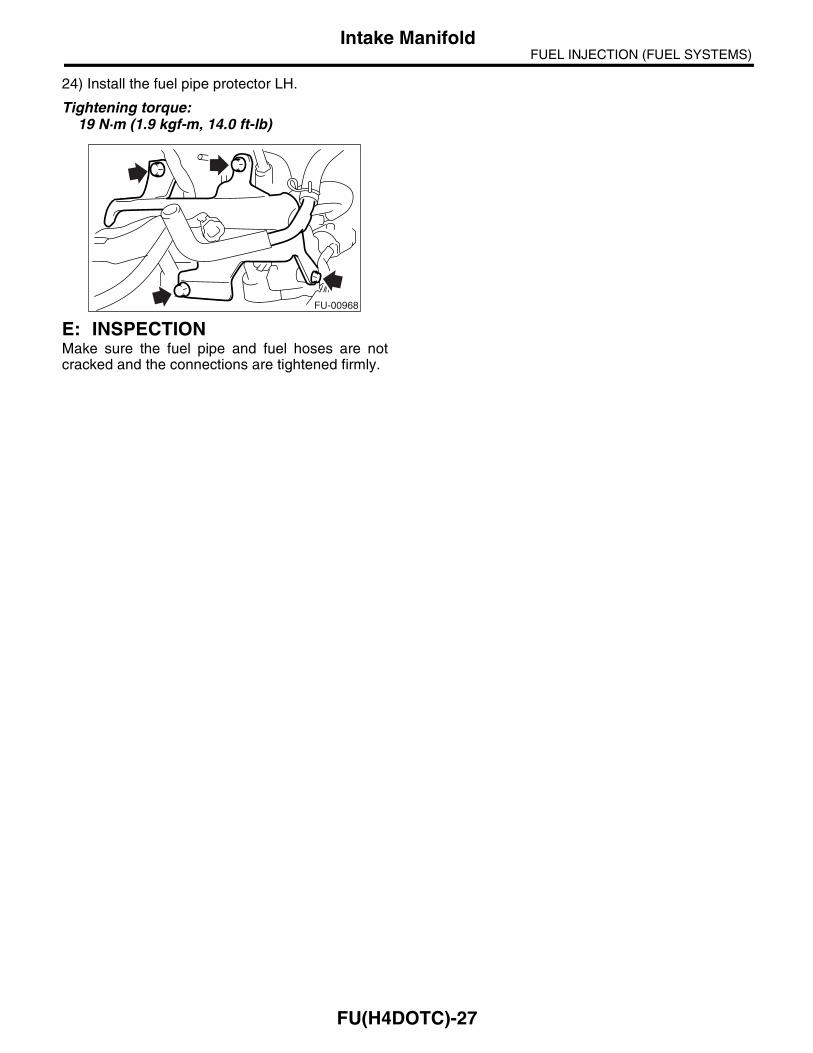
24) Install the fuel pipe protector LH.
Tightening torque:19 N·m (1.9 kgf-m, 14.0 ft-lb)
E: INSPECTIONMake sure the fuel pipe and fuel hoses are notcracked and the connections are tightened firmly.
FU-00968
FU(H4DOTC)-27

FUEL INJECTION (FUEL SYSTEMS)Engine Coolant Temperature Sensor
4. Engine Coolant Temperature Sensor
A: REMOVAL1) Disconnect the ground cable from battery.
2) Remove the generator. <Ref. to SC(H4SO)-13,REMOVAL, Generator.>3) Drain the engine coolant. <Ref. toCO(H4DOTC)-18, DRAINING OF ENGINE COOL-ANT, REPLACEMENT, Engine Coolant.>4) Disconnect the connector from engine coolanttemperature sensor.
5) Remove the engine coolant temperature sensor.
B: INSTALLATIONInstall in the reverse order of removal.
Tightening torque:18 N·m (1.8 kgf-m, 13.3 ft-lb)
FU-00009
FU-00055
FU(H4DOTC)-28
FUEL INJECTION (FUEL SYSTEMS)Crankshaft Position Sensor
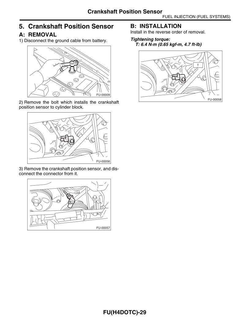
5. Crankshaft Position SensorA: REMOVAL1) Disconnect the ground cable from battery.
2) Remove the bolt which installs the crankshaftposition sensor to cylinder block.
3) Remove the crankshaft position sensor, and dis-connect the connector from it.
B: INSTALLATIONInstall in the reverse order of removal.
Tightening torque:T: 6.4 N·m (0.65 kgf-m, 4.7 ft-lb)
FU-00009
FU-00056
FU-00057
FU-00058
T
FU(H4DOTC)-29

FUEL INJECTION (FUEL SYSTEMS)Camshaft Position Sensor
6. Camshaft Position SensorA: REMOVAL1) Disconnect the ground cable from battery.
2) Disconnect the connector from camshaft posi-tion sensor.
3) Remove the camshaft position sensor from cam-shaft support LH.
B: INSTALLATIONInstall in the reverse order of removal.
Tightening torque:T: 6.4 N·m (0.65 kgf-m, 4.7 ft-lb)
FU-00009
FU-00059
FU-00060
FU-00060
FU(H4DOTC)-30
FUEL INJECTION (FUEL SYSTEMS)AVCS Camshaft Position Sensor
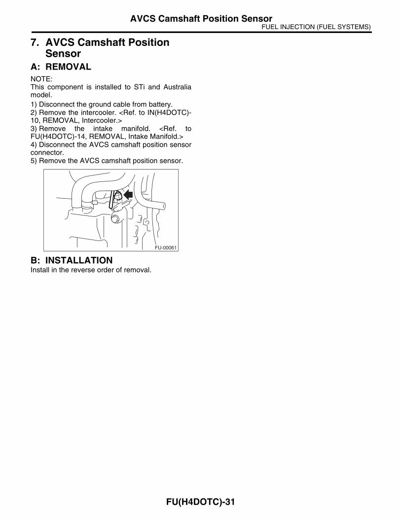
7. AVCS Camshaft Position Sensor
A: REMOVALNOTE:This component is installed to STi and Australiamodel.1) Disconnect the ground cable from battery.2) Remove the intercooler. <Ref. to IN(H4DOTC)-10, REMOVAL, Intercooler.>3) Remove the intake manifold. <Ref. toFU(H4DOTC)-14, REMOVAL, Intake Manifold.>4) Disconnect the AVCS camshaft position sensorconnector.5) Remove the AVCS camshaft position sensor.
B: INSTALLATIONInstall in the reverse order of removal.
FU-00061
FU(H4DOTC)-31
FUEL INJECTION (FUEL SYSTEMS)Knock Sensor
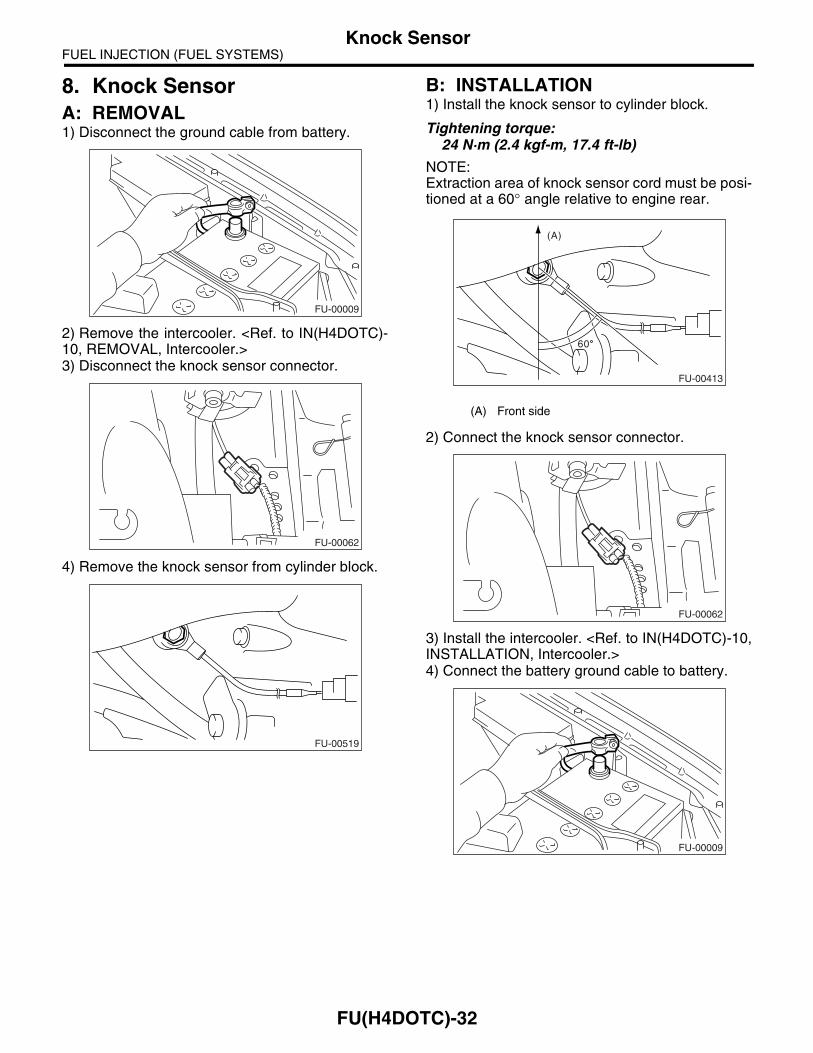
8. Knock SensorA: REMOVAL1) Disconnect the ground cable from battery.
2) Remove the intercooler. <Ref. to IN(H4DOTC)-10, REMOVAL, Intercooler.>3) Disconnect the knock sensor connector.
4) Remove the knock sensor from cylinder block.
B: INSTALLATION1) Install the knock sensor to cylinder block.
Tightening torque:24 N·m (2.4 kgf-m, 17.4 ft-lb)
NOTE:Extraction area of knock sensor cord must be posi-tioned at a 60° angle relative to engine rear.
2) Connect the knock sensor connector.
3) Install the intercooler. <Ref. to IN(H4DOTC)-10,INSTALLATION, Intercooler.>4) Connect the battery ground cable to battery.
FU-00009
FU-00062
FU-00519
(A) Front side
FU-00413
(A)
60
FU-00062
FU-00009
FU(H4DOTC)-32
FUEL INJECTION (FUEL SYSTEMS)Throttle Position Sensor
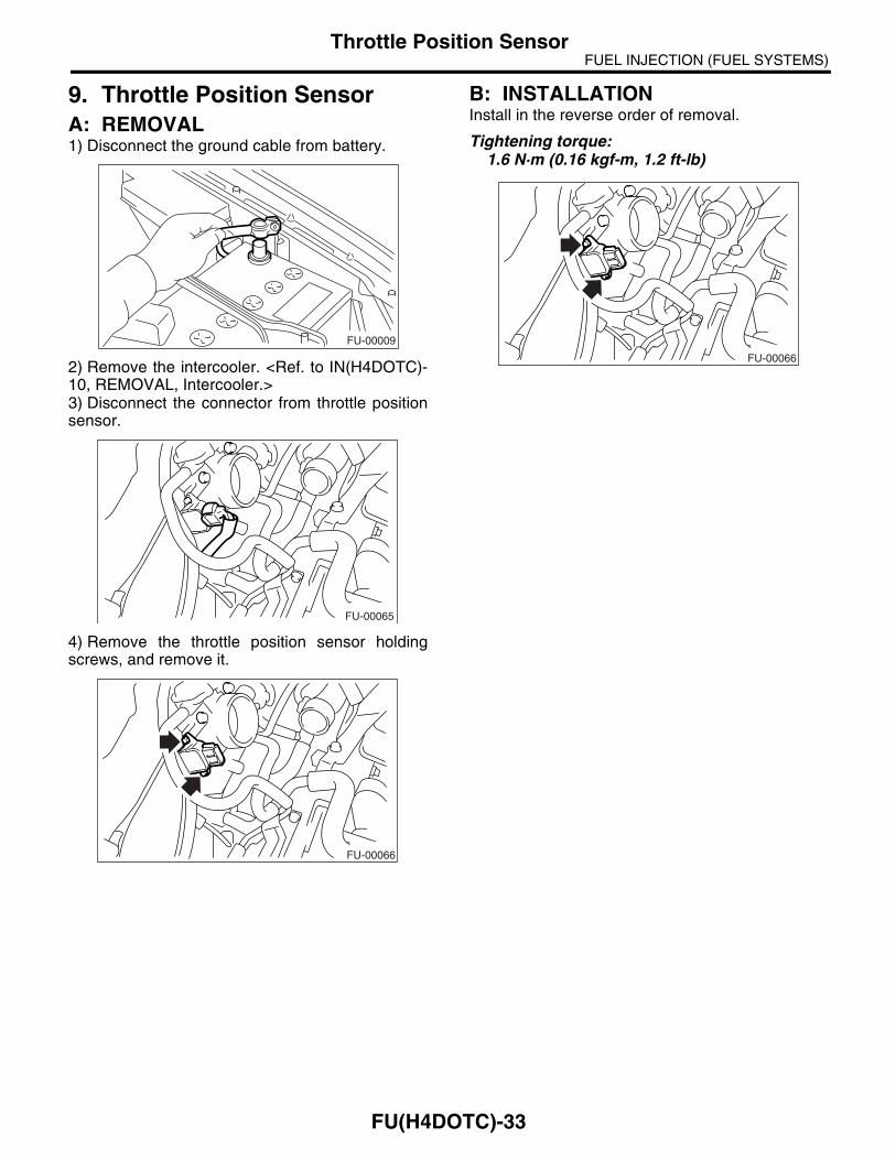
9. Throttle Position SensorA: REMOVAL1) Disconnect the ground cable from battery.
2) Remove the intercooler. <Ref. to IN(H4DOTC)-10, REMOVAL, Intercooler.>3) Disconnect the connector from throttle positionsensor.
4) Remove the throttle position sensor holdingscrews, and remove it.
B: INSTALLATIONInstall in the reverse order of removal.
Tightening torque:1.6 N·m (0.16 kgf-m, 1.2 ft-lb)
FU-00009
FU-00065
FU-00066
FU-00066
FU(H4DOTC)-33
FUEL INJECTION (FUEL SYSTEMS)Mass Air Flow and Intake Air Temperature Sensor
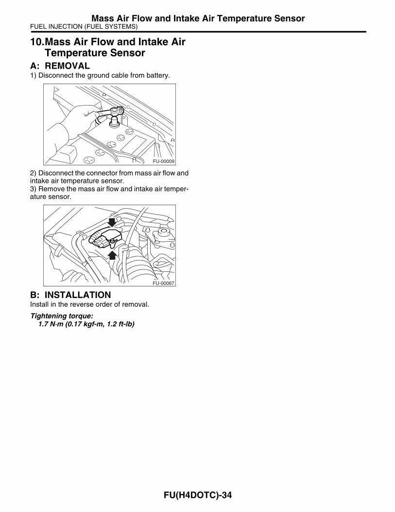
10.Mass Air Flow and Intake Air Temperature Sensor
A: REMOVAL1) Disconnect the ground cable from battery.
2) Disconnect the connector from mass air flow andintake air temperature sensor.3) Remove the mass air flow and intake air temper-ature sensor.
B: INSTALLATIONInstall in the reverse order of removal.
Tightening torque:1.7 N·m (0.17 kgf-m, 1.2 ft-lb)
FU-00009
FU-00067
FU(H4DOTC)-34
FUEL INJECTION (FUEL SYSTEMS)Manifold Absolute Pressure Sensor
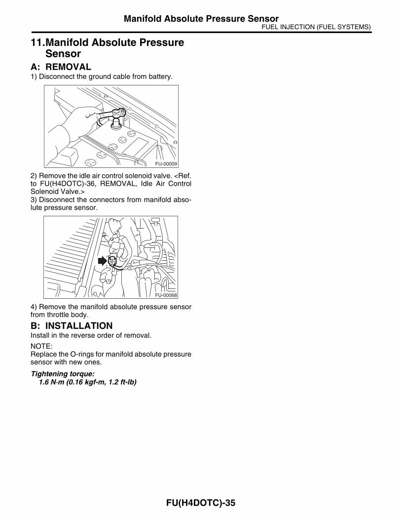
11.Manifold Absolute Pressure Sensor
A: REMOVAL1) Disconnect the ground cable from battery.
2) Remove the idle air control solenoid valve. <Ref.to FU(H4DOTC)-36, REMOVAL, Idle Air ControlSolenoid Valve.>3) Disconnect the connectors from manifold abso-lute pressure sensor.
4) Remove the manifold absolute pressure sensorfrom throttle body.
B: INSTALLATIONInstall in the reverse order of removal.
NOTE:Replace the O-rings for manifold absolute pressuresensor with new ones.
Tightening torque:1.6 N·m (0.16 kgf-m, 1.2 ft-lb)
FU-00009
FU-00068
FU(H4DOTC)-35

FUEL INJECTION (FUEL SYSTEMS)Idle Air Control Solenoid Valve
12.Idle Air Control Solenoid Valve
A: REMOVAL1) Disconnect the ground cable from battery.
2) Disconnect the connector from idle air controlsolenoid valve.
3) Remove the idle air control solenoid valve fromthrottle body.
4) Remove the gasket from throttle body.
B: INSTALLATIONInstall in the reverse order of removal.
NOTE:Replace the gasket with a new one.
Tightening torque:2.8 N·m (0.29 kgf-m, 2.1 ft-lb)
FU-00009
FU-00070
FU-00071
FU-00072
FU-00071
FU(H4DOTC)-36
FUEL INJECTION (FUEL SYSTEMS)Fuel Injector
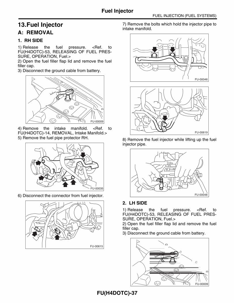
13.Fuel InjectorA: REMOVAL1. RH SIDE1) Release the fuel pressure. <Ref. toFU(H4DOTC)-53, RELEASING OF FUEL PRES-SURE, OPERATION, Fuel.>2) Open the fuel filler flap lid and remove the fuelfiller cap.3) Disconnect the ground cable from battery.
4) Remove the intake manifold. <Ref. toFU(H4DOTC)-14, REMOVAL, Intake Manifold.>5) Remove the fuel pipe protector RH.
6) Disconnect the connector from fuel injector.
7) Remove the bolts which hold the injector pipe tointake manifold.
8) Remove the fuel injector while lifting up the fuelinjector pipe.
2. LH SIDE1) Release the fuel pressure. <Ref. toFU(H4DOTC)-53, RELEASING OF FUEL PRES-SURE, OPERATION, Fuel.>2) Open the fuel filler flap lid and remove the fuelfiller cap.3) Disconnect the ground cable from battery.
FU-00009
FU-00035
FU-00615
FU-00046
FU-00619
FU-00048
FU-00009
FU(H4DOTC)-37

FUEL INJECTION (FUEL SYSTEMS)Fuel Injector
4) Remove the intake manifold. <Ref. toFU(H4DOTC)-14, REMOVAL, Intake Manifold.>5) Remove the fuel pipe protector LH.
6) Disconnect the connector from fuel injector.
7) Remove the bolts which hold the injector pipe tointake manifold.
8) Remove the fuel injector while lifting up the fuelinjector pipe.
FU-00968
FU-00615
FU-00043
FU-00618
FU-00044
FU-00048
FU(H4DOTC)-38
FUEL INJECTION (FUEL SYSTEMS)Fuel Injector
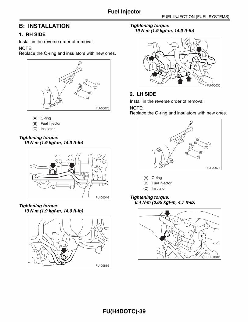
B: INSTALLATION1. RH SIDEInstall in the reverse order of removal.
NOTE:Replace the O-ring and insulators with new ones.
Tightening torque:19 N·m (1.9 kgf-m, 14.0 ft-lb)
Tightening torque:19 N·m (1.9 kgf-m, 14.0 ft-lb)
Tightening torque:19 N·m (1.9 kgf-m, 14.0 ft-lb)
2. LH SIDEInstall in the reverse order of removal.
NOTE:Replace the O-ring and insulators with new ones.
Tightening torque:6.4 N·m (0.65 kgf-m, 4.7 ft-lb)
(A) O-ring
(B) Fuel injector
(C) Insulator
FU-00073
(A)(C)
(C)
(B)
FU-00046
FU-00619
(A) O-ring
(B) Fuel injector
(C) Insulator
FU-00035
FU-00073
(A)(C)
(C)
(B)
FU-00043
FU(H4DOTC)-39

FUEL INJECTION (FUEL SYSTEMS)Fuel Injector
Tightening torque:19 N·m (1.9 kgf-m, 14.0 ft-lb)
Tightening torque:19 N·m (1.9 kgf-m, 14.0 ft-lb)
Tightening torque:19 N·m (1.9 kgf-m, 14.0 ft-lb)
FU-00044
FU-00618
FU-00968
FU(H4DOTC)-40