2001 IMPREZA SERVICE MANUAL QUICK REFERENCE INDEX … · 2001 IMPREZA SERVICE MANUAL QUICK...
50
FUJI HEAVY INDUSTRIES LTD. G1830GE6 2001 IMPREZA SERVICE MANUAL QUICK REFERENCE INDEX BODY SECTION This service manual has been prepared to provide SUBARU service personnel with the necessary information and data for the correct maintenance and repair of SUBARU vehicles. This manual includes the procedures for maintenance, disassembling, reas- sembling, inspection and adjustment of components and diagnostics for guid- ance of experienced mechanics. Please peruse and utilize this manual fully to ensure complete repair work for satisfying our customers by keeping their vehicle in optimum condition. When replacement of parts during repair work is needed, be sure to use SUBARU genuine parts. All information, illustration and specifi- cations contained in this manual are based on the latest product information available at the time of publication approval. HVAC SYSTEM (HEATER, VENTILATOR AND A/C) AC HVAC SYSTEM (AUTO A/C) (DIAGNOSTICS) AC AIRBAG SYSTEM AB AIRBAG SYSTEM (DIAGNOSTICS) AB SEAT BELT SYSTEM SB LIGHTING SYSTEM LI WIPER AND WASHER SYSTEMS WW ENTERTAINMENT ET COMMUNICATION SYSTEM COM GLASS/WINDOWS/MIRRORS GW BODY STRUCTURE BS INSTRUMENTATION/DRIVER INFO IDI SEATS SE SECURITY AND LOCKS SL IMMOBILIZER (DIAGNOSTICS) IM SUNROOF/T-TOP/CONVERTIBLE TOP (SUNROOF) SR EXTERIOR/INTERIOR TRIM EI
Transcript of 2001 IMPREZA SERVICE MANUAL QUICK REFERENCE INDEX … · 2001 IMPREZA SERVICE MANUAL QUICK...

2001 IMPREZA SERVICE MANUAL QUICK REFERENCE INDEX
BODY SECTION
This service manual has been preparedto provide SUBARU service personnelwith the necessary information and datafor the correct maintenance and repairof SUBARU vehicles.This manual includes the proceduresfor maintenance, disassembling, reas-sembling, inspection and adjustment ofcomponents and diagnostics for guid-ance of experienced mechanics.Please peruse and utilize this manualfully to ensure complete repair work forsatisfying our customers by keepingtheir vehicle in optimum condition.When replacement of parts duringrepair work is needed, be sure to useSUBARU genuine parts.
All information, illustration and specifi-cations contained in this manual arebased on the latest product informationavailable at the time of publicationapproval.
FUJI HEAVY INDUSTRIES LTD.
HVAC SYSTEM (HEATER, VENTILATOR AND A/C)
AC
HVAC SYSTEM (AUTO A/C)(DIAGNOSTICS)
AC
AIRBAG SYSTEM AB
AIRBAG SYSTEM (DIAGNOSTICS) AB
SEAT BELT SYSTEM SB
LIGHTING SYSTEM LI
WIPER AND WASHER SYSTEMS WW
ENTERTAINMENT ET
COMMUNICATION SYSTEM COM
GLASS/WINDOWS/MIRRORS GW
BODY STRUCTURE BS
INSTRUMENTATION/DRIVER INFO IDI
SEATS SE
SECURITY AND LOCKS SL
IMMOBILIZER (DIAGNOSTICS) IM
SUNROOF/T-TOP/CONVERTIBLE TOP (SUNROOF)
SR
EXTERIOR/INTERIOR TRIM EI
G1830GE6

2001 IMPREZA SERVICE MANUAL QUICK REFERENCE INDEX
BODY SECTION
EXTERIOR BODY PANELS EB
CRUISE CONTROL SYSTEM CC
CRUISE CONTROL SYSTEM (DIAGNOSTICS)
CC
G1830GE6
SECURITY AND LOCKS
SL
Page1. General Description ....................................................................................22. Door Lock Control System ..........................................................................83. Keyless Entry System ...............................................................................154. Front Inner Remote ...................................................................................285. Front Outer Handle ...................................................................................296. Front Door Latch Assembly.......................................................................307. Front Door Lock Actuator ..........................................................................318. Rear Inner Remote....................................................................................329. Rear Outer Handle ....................................................................................33
10. Rear Door Latch Assembly .......................................................................3411. Rear Door Lock Actuator...........................................................................3512. Rear Gate Outer Handle ...........................................................................3613. Rear Gate Latch Assembly .......................................................................3714. Rear Gate Latch Lock Actuator.................................................................3815. Trunk Lid Lock Assembly ..........................................................................3916. Front Hood Lock Assembly .......................................................................4017. Remote Openers.......................................................................................4118. Ignition Key Lock.......................................................................................4219. Key Lock Cylinders ...................................................................................4320. Immobilizer Control Module ......................................................................4421. Immobilizer Antenna .................................................................................4522. Keyless Entry Control Module...................................................................4623. Keyless Transmitter ..................................................................................47

SECURITY AND LOCKSGENERAL DESCRIPTION
1. General DescriptionA: SPECIFICATIONS
B: COMPONENT1. DOOR LOCK ASSEMBLY
(1)
(1)
(2)
(2)
(3)
(3)
(7)
(7)
(8) T2
T3
(4)
(4)
(5)
(6)
(5)
T3
(6)
T2T1
FRONT
REAR
BO0242
(1) Inner remote ASSY (6) Striker Tightening torque: N·m (kgf-m, ft-lb)(2) Inner remote cover (7) Door outer handle T1: 6.4 (0.65, 4.7)(3) Bell crank (8) Key cylinder T2: 7.4 (0.75, 5.4)(4) Auto-door lock actuator T3: 14 (1.4, 10.1)(5) Door latch
SL-2

SECURITY AND LOCKSGENERAL DESCRIPTION
2. TRUNK LID AND REAR GATE LOCK
BO0243
(1)
(1)
(6)
(4)
(5)
(3)
(3)
(2)
T3
T2
T2
T1
TRUNK REAR GATE
(1) Key cylinder (5) Rear gate outer handle Tightening torque: N·m (kgf-m, ft-lb)(2) Cable (6) Rear gate actuator T1: 7.4 (0.75, 5.4)(3) Striker T2: 25 (2.5, 18.1)(4) Trunk lid lock ASSY
SL-3
SECURITY AND LOCKSGENERAL DESCRIPTION
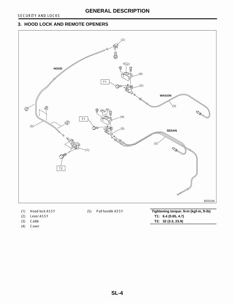
3. HOOD LOCK AND REMOTE OPENERS
HOOD
(2)
(4)
(5)
(4)
(3)
(3)
(3)
(1)
(5)
T1
T1
T2
WAGON
SEDAN
BO0244
(1) Hood lock ASSY (5) Pull handle ASSY Tightening torque: N·m (kgf-m, ft-lb)(2) Lever ASSY T1: 6.4 (0.65, 4.7)(3) Cable T2: 32 (3.3, 23.9)(4) Cover
SL-4
SECURITY AND LOCKSGENERAL DESCRIPTION
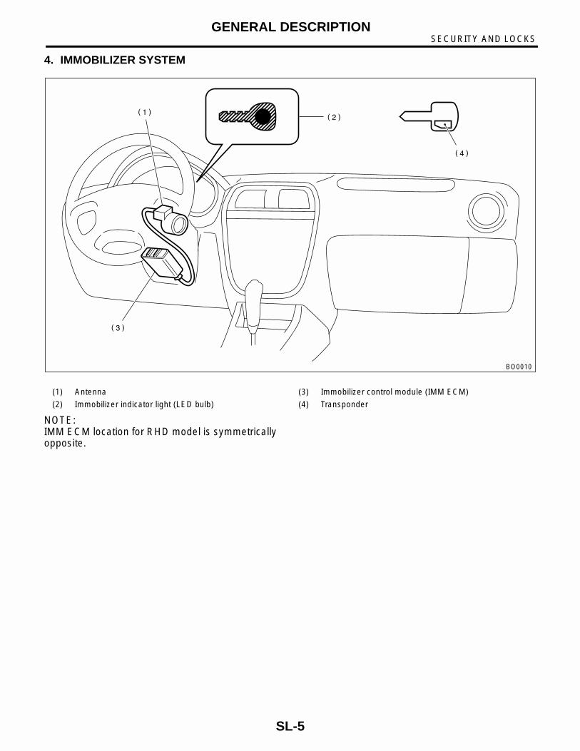
4. IMMOBILIZER SYSTEM
NOTE:IMM ECM location for RHD model is symmetricallyopposite.
BO0010
(1) Antenna (3) Immobilizer control module (IMM ECM)
(2) Immobilizer indicator light (LED bulb) (4) Transponder
SL-5

SECURITY AND LOCKSGENERAL DESCRIPTION
5. KEYLESS ENTRY SYSTEM
C: CAUTION• Before disassembling or reassembling parts,always disconnect battery ground cable. Whenrepairing radio, control module, etc. which areprovided with memory functions, recordmemory contents before disconnecting batteryground cable. Otherwise, these contents arecancelled upon disconnection.• Reassemble parts in reverse order ofdisassembly procedure unless otherwiseindicated.• Adjust parts to specifications contained inthis manual if so designated.• Connect connectors and hoses securelyduring reassembly.• After reassembly, ensure functional partsoperate smoothly.• Airbag system wiring harness is routed nearthe electrical parts and switch.• All airbag system wiring harness andconnectors are colored yellow. Do not useelectrical test equipment on these circuits.• Be careful not to damage Airbag systemwiring harness when servicing the ignition keycylinder.
BO0192
(1) Keyless entry control module (2) Rear gate latch switch (Wagon) (3) Door switch
SL-6

SECURITY AND LOCKSGENERAL DESCRIPTION
D: PREPARATION TOOL1. SPECIAL TOOLS
2. GENERAL TOOLS
ILLUSTRATION TOOL NUMBER DESCRIPTION REMARKS
925580000 PULLER Used for removing trim clip
B5M1120
TOOL NAME REMARKS
Circuit Tester Used for measuring resistance and voltage.
Drill Used for replacing ignition key lock.
SL-7
SECURITY AND LOCKSDOOR LOCK CONTROL SYSTEM
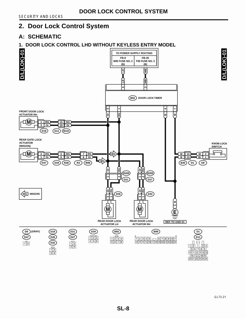
2. Door Lock Control System
A: SCHEMATIC1. DOOR LOCK CONTROL LHD WITHOUT KEYLESS ENTRY MODEL
D/L
(LO
K)-
01
D/L
(LO
K)-
01
W 2Br 1
1413
D8
D18
RG1Or3
B101D11
RG15Or10
R38D34
RG5Or6
B99R3
RG7Or6
KNOB-LOCKSWITCH
FRONT DOOR LOCKACTUATOR RH
D47
RG2Or
D1B30
WB1
REAR GATE LOCKACTUATOR(WAGON)
: WAGONWG
LR
WB
FB-9M/B FUSE NO. 2
(B)
FB-35F/B FUSE NO. 3
(B)
TO POWER SUPPLY ROUTING
DOOR LOCK TIMER
LR
WB
6 2
B92
Or
RG WB
3 1 74
D26
Or
3R
G1
REAR DOOR LOCKACTUATOR LH
D32
Or
3R
G1
B269
D21
Or
1
RG
2
B265
D27
Or
1R
G2
REAR DOOR LOCKACTUATOR RH
B
REF. TO GND-01
WG
WG
D8
D47
(GRAY)
1 2
D26
D32
D18
1 23 4
B92
1 2 3 45 6 7 8
D27
D21
1 23 4
D34
1 2 34 5 6
B99
2 3 4 5 6 7 813 15 1614 17 18 19 20 21
922
10121
231124
D11
D1
1 26 7
10 11 12 13 14 1516 17 18 19
3 45
20 21 22 23 24 25
98
GL73-21
SL-8

SECURITY AND LOCKSDOOR LOCK CONTROL SYSTEM
2. DOOR LOCK CONTROL RHD WITHOUT KEYLESS ENTRY MODEL
GR73-21
D/L
(RO
K)-
01
D/L
(RO
K)-
01
W 2Br 1
1413
D8
D18
RG1LgB3
B101D11
RG15LgB10
R38D34
RG5LgB6
B97R1
RG8LgB4
KNOB-LOCKSWITCH
FRONT DOOR LOCKACTUATOR LH
D47
RG2LgB
D1B30
WB1
REAR GATE LOCKACTUATOR(WAGON)
: WAGONWG
LR
WB
MB-10M/B FUSE NO. 2
(B)
FB-35F/B FUSE NO. 3
(B)
TO POWER SUPPLY ROUTING
DOOR LOCK TIMER
LR
WB
6 2
B92
Lg
B
RG WB
3 1 74
D26
Lg
B3
RG
1
REAR DOOR LOCKACTUATOR LH
D32
Lg
B3
RG
1
B269
D21
Lg
B1
RG
2
B265
D27
Lg
B1
RG
2
REAR DOOR LOCKACTUATOR RH
B
REF. TO GND-01
WG
WG
D8
D47
(GRAY)
1 2
D26
D32
D18
1 23 4
B92
1 2 3 45 6 7 8
1 2 3 45 6 7 8
B97
D27
D21
1 23 4
D34
1 2 34 5 6
D11
D1
1 26 7
10 11 12 13 14 1516 17 18 19
3 45
20 21 22 23 24 25
98
SL-9

SECURITY AND LOCKSDOOR LOCK CONTROL SYSTEM
3. DOOR LOCK CONTROL LHD WITH KEYLESS ENTRY MODEL
GL73-20
D/L
(LW
K)-
01
D/L
(LW
K)-
01
D18
RG1Or3
R38 R3D34
RG5Or6
B99
RG7Or
RGOr 6
FRONT DOORLOCK ACTUATOR RH
FRONT DOORLOCK ACTUATOR LH
D47
RG2Or1
REAR GATELOCK ACTUATOR(WAGON)
: WAGONWG
WB
LR
FB-35F/B FUSE NO. 3
(B)
FB-9M/B FUSE NO. 2
(B)
TO POWER SUPPLY ROUTING
KEYLESS ENTRYCONTROL MODULE
WB
LR
16 5
B176
B B WRG
6 14
Or
18 717
D26
Or
3R
G1
REAR DOOR LOCKACTUATOR LH
REAR DOOR LOCKACTUATOR RH
D32
Or
3R
G1
D72D1B30
B265
D27
Or
RG
B269
D21
Or
1R
G2 1 2
B
REF. TO GND-01
WG
RG 1
Or 3
W 4
Br 2
RG 15
Or 10
W
RG
Or
W14B101D11
RG15Or
RGOr 10
WG
B Br13
D18
D26
D32
1 23 4
D72 (GRAY)
B176
2 3 4 5 6 71 8 9 1011 12 13 14 15 16 17 18
D47
1 2 D27
D21
1 23 4
D34
1 2 34 5 6
B99
2 3 4 5 6 7 813 15 1614 17 18 19 20 21
922
10121
231124
D11
D1
1 26 7
10 11 12 13 14 1516 17 18 19
3 45
20 21 22 23 24 25
98
SL-10

SECURITY AND LOCKSDOOR LOCK CONTROL SYSTEM
4. DOOR LOCK CONTROL RHD WITH KEYLESS ENTRY MODEL
GR73-20
D/L
(RW
K)-
01
D/L
(RW
K)-
01
D18
RG1LgB3
R38 R1D34
RG5LgB6
B97
RG8LgB
RGLgB 4
FRONT DOORLOCK ACTUATOR LH
FRONT DOORLOCK ACTUATOR RH
D47
RG2LgB1
REAR GATELOCK ACTUATOR(WAGON)
: WAGONWG
WB
LR
FB-35F/B FUSE NO. 3
(B)
MB-10M/B FUSE NO. 2
(B)
TO POWER SUPPLY ROUTING
KEYLESS ENTRYCONTROL MODULE
WB
LR
16 5
B176
B B WRG
6 14
Lg
B18 717
D26
Lg
B3
RG
1
REAR DOOR LOCKACTUATOR LH
REAR DOOR LOCKACTUATOR RH
D32
Lg
B3
RG
1
D72D1B30
B265
D27
Lg
BR
G
B269
D21
Lg
B1
RG
2 1 2
B
REF. TO GND-01
WG
RG 1
LgB 3
W 4
Br 2
RG 15
LgB 10
W
RG
LgB
W14B101D11
RG15LgB
RGLgB 10
WG
B Br13
D18
D26
D32
1 23 4
D72 (GRAY)
B176
2 3 4 5 6 71 8 9 1011 12 13 14 15 16 17 18
D47
1 2 D27
D21
1 23 4
D34
1 2 34 5 6 7 8
B97
1 2 3 45 6
D11
D1
1 26 7
10 11 12 13 14 1516 17 18 19
3 45
20 21 22 23 24 25
98
SL-11

SECURITY AND LOCKSDOOR LOCK CONTROL SYSTEM
B: INSPECTION1. SYMPTOM CHART
2. CHECK FUSE
3. CHECK POWER SUPPLY AND GROUND CIRCUIT
Symptom Repair order Reference
The door lock control system does not operate.
1. Check the fuse. <Ref. to SL-12, CHECK FUSE, INSPECTION, Door Lock Control System.>
2. Check the power supply and ground circuit for the door lock timer (without keyless entry) or key-less entry control module (with keyless entry).
<Ref. to SL-12, CHECK POWER SUPPLY AND GROUND CIRCUIT, INSPECTION, Door Lock Control System.>
3. Check the door lock switch and the circuit. <Ref. to SL-13, CHECK DOOR LOCK SWITCH AND CIRCUIT, INSPECTION, Door Lock Control System.>
4. Check the door lock actuator and the circuit. <Ref. to SL-14, CHECK DOOR LOCK ACTUATOR AND CIRCUIT, INSPECTION, Door Lock Control System.>
The door lock switch (knob) does not operate.
Check the door lock switch and the circuit. <Ref. to SL-13, CHECK DOOR LOCK SWITCH AND CIRCUIT, INSPECTION, Door Lock Control System.>
A specific door lock actuator does not operate.
Check the door lock actuator and the circuit. <Ref. to SL-14, CHECK DOOR LOCK ACTUATOR AND CIRCUIT, INSPECTION, Door Lock Control System.>
Step Check Yes No1 CHECK FUSE.
Remove and visually check fuse No. 2 (in the main fuse box) and No. 3 (in the fuse and relay box).
Is the fuse blown (15A)? Replace the fuse with a new one.
Check power sup-ply and ground cir-cuit. <Ref. to SL-12, CHECK POWER SUPPLY AND GROUND CIRCUIT, INSPECTION, Door Lock Control System.>
Step Check Yes No1 CHECK POWER SUPPLY.
1)Disconnect the door lock timer or keyless entry control module harness connector.2)Measure the voltage between the harness connector terminal and chassis ground.
Connector & terminalWithout keyless entry:
(B92) No. 2 (+) — Chassis ground (–):(B92) No. 6 (+) — Chassis ground (–):
With keyless entry:(B176) No. 5 (+) — Chassis ground (–):(B176) No. 16 (+) — Chassis ground (–):
Is the voltage more than 10 V? Go to step 2. Check the harness for open circuits or shorts between the door lock timer or keyless entry control module and the fuse.
SL-12

SECURITY AND LOCKSDOOR LOCK CONTROL SYSTEM
4. CHECK DOOR LOCK SWITCH AND CIR-CUIT
2 CHECK GROUND CIRCUIT.Measure the resistance between the harness connector terminal and chassis ground.
Connector & terminalWithout keyless entry:
(B92) No. 4 (+) — Chassis ground (–):With keyless entry:
(B176) No. 6 (+) — Chassis ground (–):(B176) No. 14 (+) — Chassis ground (–):
Is the resistance less than 10 Ω?
Power supply and ground circuit is OK.
Repair harness.
Step Check Yes No
Step Check Yes No1 CHECK DOOR LOCK CONTROL SYSTEM
TYPE.Is the vehicle equipped with keyless entry system?
Go to step 6. Go to step 2.
2 CHECK DOOR LOCK SWITCH CIRCUIT.1)Disconnect the door lock timer harness con-nector.2)Measure the resistance between the har-ness connector terminal and chassis ground when moving the driver's door lock knob to UNLOCK.
Connector & terminal(B92) No. 7 (+) — Chassis ground (–):
Is the resistance less than 10 Ω?
Go to step 3. Go to step 4.
3 CHECK DOOR LOCK SWITCH CIRCUIT.Measure the resistance between the harness connector terminal and chassis ground when the driver's door lock knob is moved to LOCK.
Connector & terminal(B92) No. 7 (+) — Chassis ground (−−−−):
Is the resistance less than 10 Ω?
Go to step 4. The door lock switch is OK.
4 CHECK DOOR LOCK SWITCH.1)Disconnect the driver's door lock switch har-ness connector.2)Check the continuity between the door lock switch terminals when moving the door lock knob to UNLOCK.
TerminalNo. 1 — No. 2:
Does continuity exist? Go to step 5. Replace the door lock switch.
5 CHECK DOOR LOCK SWITCH.Check the continuity between the door lock switch terminals when moving the door lock knob to LOCK.
TerminalNo. 1 — No. 2:
Does continuity exist? Replace the door lock switch.
Check the harness for open circuits or shorts between the door lock timer and the door lock switch.
6 CHECK DOOR LOCK SWITCH CIRCUIT.1)Disconnect the keyless entry control module harness connector.2)Measure the resistance between the har-ness connector terminal and chassis ground when moving the driver's door lock knob to UNLOCK.
Connector & terminal(B176) No. 7 (+) — Chassis ground (–):
Is the resistance less than 10 Ω?
Go to step 7. Go to step 8.
SL-13

SECURITY AND LOCKSDOOR LOCK CONTROL SYSTEM
5. CHECK DOOR LOCK ACTUATOR AND CIRCUIT
7 CHECK DOOR LOCK SWITCH CIRCUIT.Measure the resistance between the harness connector terminal and chassis ground when the driver's door lock knob is moved to LOCK.
Connector & terminal(B176) No. 7 (+) — Chassis ground (–):
Is the resistance less than 10 Ω?
Go to step 8. The door lock switch is OK.
8 CHECK DOOR LOCK SWITCH.1)Disconnect the driver's door lock switch (actuator) harness connector.2)Check the continuity between the door lock switch terminals when moving the door lock knob to UNLOCK.
TerminalNo. 2 — No. 4:
Does continuity exist? Go to step 9. Replace the door lock switch (actua-tor).
9 CHECK DOOR LOCK SWITCH.Check the continuity between the door lock switch terminals when moving the door lock knob to LOCK.
TerminalNo. 2 — No. 4:
Does continuity exist? Replace the door lock switch (actua-tor).
Check the harness for open circuits or shorts between the keyless entry control module and the door lock switch.
Step Check Yes No
Step Check Yes No1 CHECK OUTPUT SIGNAL.
Measure the voltage between the harness con-nector terminal and chassis ground when mov-ing the door lock knob to LOCK.
Connector & terminalWithout keyless entry:
(B92) No. 3 — Chassis ground:With keyless entry:
(B176) No. 18 (+) — Chassis ground (–):
Is the voltage more than 10 V? Go to step 2. Replace the door lock timer or key-less entry control module.
2 CHECK OUTPUT SIGNAL.Measure the voltage between the harness con-nector terminal and chassis ground when mov-ing the door lock knob to UNLOCK.
Connector & terminalWithout keyless entry:
(B92) No. 1 — Chassis ground:With keyless entry:
(B176) No. 17 (+) — Chassis ground (–):
Is the voltage more than 10 V? Go to step 3. Replace the door lock timer or key-less entry control module.
3 CHECK DOOR LOCK ACTUATOR.Check the door lock actuator.Front door lock actuator: <Ref. to SL-31, Front Door Lock Actuator.>Rear door lock actuator: <Ref. to SL-35, Rear Door Lock Actuator.>Rear gate latch lock actuator: <Ref. to SL-38, Rear Gate Latch Lock Actuator.>
Is the door lock actuator OK? Check the harness for open circuits or shorts between the door lock timer or keyless entry control module and the door lock actuator.
Replace the door lock actuator.
SL-14

SECURITY AND LOCKSKEYLESS ENTRY SYSTEM
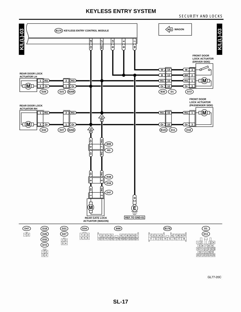
3. Keyless Entry SystemA: SCHEMATIC1. KEYLESS ENTRY LHD MODEL
K/L
(L)-
01
K/L
(L)-
01
WB W
FB-35F/B FUSE NO. 3
(B)
MB-6M/B FUSE NO. 6
(B)
TO POWER SUPPLY ROUTING
BG
WB W WR
12
Lg
B13 16 15 1
KEYLESS ENTRY CONTROL MODULEB176
W23
W
F45
B62
WWR
21
KEY WARNINGSWITCH
B74
B74
12
(BLACK)
RE
F. T
O T
UR
N(L
)-01
B176
2 3 4 5 6 71 8 9 1011 12 13 14 15 16 17 18
F45
2 3 4 5 6 7 813 15 1614 17 18 19 20 21
922
10121
231124
GL77-20A
SL-15

SECURITY AND LOCKSKEYLESS ENTRY SYSTEM
YR L
R
K/L
(L)-
02
K/L
(L)-
02
LRY
11
BL
253
13
LOr
4 YRYR
B
LWB
13
LR
LR
20FRONT DOORSWITCH LH
B267
13
YB
FRONT DOORSWITCH RH
B268
13
YB
REAR DOORSWITCH RH
R16
12
YRB
D46
13
YB
REAR DOORSWITCH LH
R22
Y B14
20Y A
10L
R
B37
i2
A:
COMBINATIONMETERDOOR
CODEENTRYCONNECTOR
REAR GATE LATCHSWITCH (WAGON)
DIODE(WAGON)
i10
B: i11
LO
r7
Y1 2
YR
B
REF. TO GND-03
i2
B37
R30
B183
B184
i1
B36
REF. TO GND-03
B
B
B
B267R30 D46
B268
R22
R16
123
B176
(GREEN)B: i11
1 2 3 8 9 104 11 12 13 1422 23
5 6 715 16 17 24 25 2618 27 28 29 3019 20 21
B176 KEYLESS ENTRY CONTROL MODULE
1
2
3
LR
L
B
DOOR
OFF
ON
4
2
3
LR
YR
B
R52R50B90
ROOM LIGHT
TO POWER SUPPLY ROUTING
FB-9M/B FUSE NO. 2
(B)
R52 D35
1 2 3
REF. TO GND-02•03
B
2 3 4 5 6 71 8 9 1011 12 13 14 15 16 17 18
BL
B1
B99
D34R38
D35R39
R3
YY
24
B90 D34
3 41 2
i2
B99
2 3 4 5 6 7 813 15 1614 17 18 19 20 21
922
10121
231124
B36
2 3 4 5 6 7 813 15 1614 17 18 19 20 2112
1
1 2 3 4 5 6 7 8 9 10
(GREEN)i10A:
3 BB
B
REF. TO GND-04•05
WG
: WAGONWG
3 41 21 2 1
212
1 34 5 6
2
GL77-20B
SL-16
SECURITY AND LOCKSKEYLESS ENTRY SYSTEM
GL77-20C
K/L
(L)-
03
K/L
(L)-
03
W7
B6
B14
RG
17
Or
18
D34
D47
R38
R3
B99
KEYLESS ENTRY CONTROL MODULEB176
D72
B101 D11
B30 D1
RG 1
BR 2
W 4
Or 3
RG 15
Or 10
W 14
B 13
D18
RG 1
Or 3
RG 15
Or 10
Or
6O
r
RG
7R
G
Or
61
RG
52
Or
RG
WG
D26 B269D21
RG1
Or3
RG2
Or1
: WAGONWG
FRONT DOOR LOCK ACTUATOR(DRIVER SIDE)
FRONT DOORLOCK ACTUATOR(PASSENGER SIDE)
REAR DOOR LOCKACTUATOR LH
REAR GATE LOCKACTUATOR (WAGON)
D18
D32
D72
D26
B
D32 B265D27
RG1
Or3
RG2
Or1
REAR DOOR LOCKACTUATOR RH
REF. TO GND-01
1 23 4
WG
B176
2 3 4 5 6 71 8 9 1011 12 13 14 15 16 17 18
B99
2 3 4 5 6 7 813 15 1614 17 18 19 20 21
922
10121
231124
D11
D1
1 26 7
10 11 12 13 14 1516 17 18 19
3 45
20 21 22 23 24 25
98
D47
1 2
D34
1 34 5 6
2D27
D21
3 41 2
SL-17

SECURITY AND LOCKSKEYLESS ENTRY SYSTEM
2. KEYLESS ENTRY RHD MODELK
/L(R
)-01
K/L
(R)-
01
WB W
FB-35F/B FUSE NO. 3
(B)
MB-6M/B FUSE NO. 6
(B)
TO POWER SUPPLY ROUTING
WB W WR
16 15 1
KEYLESS ENTRY CONTROL MODULEB176
WWR
21
KEY WARNINGSWITCH
B74
B74
12
(BLACK) B176
2 3 4 5 6 71 8 9 1011 12 13 14 15 16 17 18
GR77-20A
SL-18

SECURITY AND LOCKSKEYLESS ENTRY SYSTEM
GR77-20B
YR L
R
K/L
(R)-
02
K/L
(R)-
02
LR
LO
r
11
BL
253
13
LOr
4 YRYR
B
YB
14
Y1
YR
2
LR
3
FRONT DOORSWITCH RH
B267
13
YB
FRONT DOORSWITCH LH
B268
13
YB
REAR DOORSWITCH RH
R16
13
YB
REAR DOORSWITCH LH
R22
5L
Or
A10
LR
B37
i2
A:
COMBINATIONMETERDOOR
CODEENTRYCONNECTOR
DIODE(WAGON)
i10
B: i11
Y17
B
REF. TO GND-03
i2
B37
B183
R30
B184
R38 D34
3 BB
R39 D35
i1
B36
REF. TO GND-03
BB B
B267
B268
R22
R16
123
B176
(GREEN)B: i11
1 2 3 8 9 104 11 12 13 1422 23
5 6 715 16 17 24 25 2618 27 28 29 3019 20 21
B176 KEYLESS ENTRY CONTROL MODULE
1
2
3
LR
L
B
DOOR
OFF
ON
4
2
3
LR
YR
B
R52
D46
R50B90
ROOM LIGHT
REAR GATE LATCHSWITCH (WAGON)
TO POWER SUPPLY ROUTING
MB-10M/B FUSE NO. 2
(B)
R52
1 2 3
REF. TO GND-02•03
B
2 3 4 5 6 71 8 9 1011 12 13 14 15 16 17 18
BL
B1
B99
R3
YY
4
B90
3 41 2
i2
B99
2 3 4 5 6 7 813 15 1614 17 18 19 20 21
922
10121
231124
B36
2 3 4 5 6 7 813 15 1614 17 18 19 20 21
922
10121
231124
1 2 3 4 5 6 7 8 9 10
(GREEN)i10A:
B13LOr
LR
LR
21
i3
B38
LR
AT
TM
WG
TM
: AT MODEL
: MT MODEL
AT
MT
: WAGONWG
i1
1 2 3 4 5 67 8 9 10 11 12 13 14
i3
3 4 5 6 7 81 217 18 19 20
921 2211 12 13 14 15 16
10
AT
B
REF. TO GWD-04•05
YB 1B 2
R30
1 2
D46 BLACK
1212
D35
3 41 2
D34
1 34 5 6
2
SL-19

SECURITY AND LOCKSKEYLESS ENTRY SYSTEM
K/L
(R)-
03
K/L
(R)-
03
W7
B6
B14
RG
17
Lg
B18
D34
D47
R38
R1
B97
KEYLESS ENTRY CONTROL MODULEB176
D72
B101 D11
B30 D1
RG 1
BR 2
W 4
LgB 3
RG 15
LgB 10
W 14
B 13
D18
RG 1
LgB 3
RG 15
LgB 10
Lg
B4
Lg
B
RG
8R
G
Lg
B6
1
RG
52
Lg
B
RG
WG
D26 B269D21
RG1
LgB3
RG2
LgB1
: WAGONWG
FRONT DOOR LOCK ACTUATOR(DRIVER SIDE)
FRONT DOORLOCK ACTUATOR(PASSENGER SIDE)
REAR DOOR LOCKACTUATOR LH
REAR GATE LOCKACTUATOR (WAGON)
D18 D32
D72D26
B
D32 B265D27
RG1
LgB3
RG2
LgB1
REAR DOOR LOCKACTUATOR RH
REF. TO GND-01
1 23 4
WG
B176
2 3 4 5 6 71 8 9 1011 12 13 14 15 16 17 18
D11
D1
1 26 7
10 11 12 13 14 1516 17 18 19
3 45
20 21 22 23 24 25
98
D47
1 2
D34
1 34 5 6
2D27
D21
3 41 2
B97
1 2 3 45 6 7 8
GR77-20C
SL-20

SECURITY AND LOCKSKEYLESS ENTRY SYSTEM
B: ELECTRICAL SPECIFICATION
B5M1141
Content Terminal No. Measuring condition
Key warning switch 1 (INPUT) Battery voltage is present when inserting the key into the ignition switch.
Registration connector 2 (INPUT) 0 V is present when connecting the registration connector.
Door switch 3 (INPUT) 0 V is present when any door is open.
Power supply 5 Battery voltage is constantly present.
Ground 6 0 V is constantly present.
Door lock switch 7 (INPUT) 0 V is present when driver's door is unlocked.
Empty 8 —
Empty 9 —
Empty 10 —
Room light 11 (OUTPUT)• 0 V is present when pressing the transmitter OPEN button.• 0 V is present when any door is open.
Turn signal light (Right) 12 (OUTPUT)Battery voltage is present when pressing the transmitter OPEN or LOCK button.
Turn signal light (Left) 13 (OUTPUT)Battery voltage is present when pressing the transmitter OPEN or LOCK button.
Ground 14 0 V is constantly present.
Power supply (Hazard light) 15 Battery voltage is constantly present.
Power supply 16 Battery voltage is constantly present.
Door and rear gate lock actuator (Unlock)
17 (OUTPUT) Battery voltage is present when pressing the transmitter OPEN button.
Door and rear gate lock actuator (Lock)
18 (OUTPUT) Battery voltage is present when pressing the transmitter LOCK button.
SL-21
SECURITY AND LOCKSKEYLESS ENTRY SYSTEM
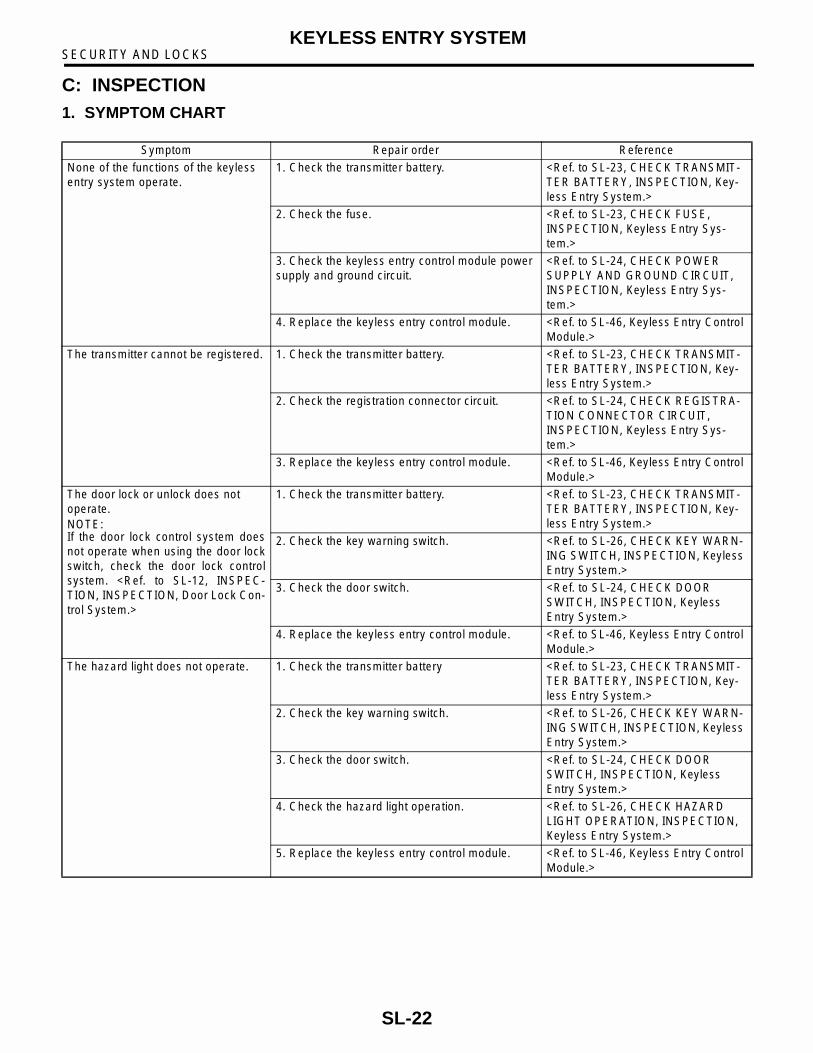
C: INSPECTION1. SYMPTOM CHART
Symptom Repair order Reference
None of the functions of the keyless entry system operate.
1. Check the transmitter battery. <Ref. to SL-23, CHECK TRANSMIT-TER BATTERY, INSPECTION, Key-less Entry System.>
2. Check the fuse. <Ref. to SL-23, CHECK FUSE, INSPECTION, Keyless Entry Sys-tem.>
3. Check the keyless entry control module power supply and ground circuit.
<Ref. to SL-24, CHECK POWER SUPPLY AND GROUND CIRCUIT, INSPECTION, Keyless Entry Sys-tem.>
4. Replace the keyless entry control module. <Ref. to SL-46, Keyless Entry Control Module.>
The transmitter cannot be registered. 1. Check the transmitter battery. <Ref. to SL-23, CHECK TRANSMIT-TER BATTERY, INSPECTION, Key-less Entry System.>
2. Check the registration connector circuit. <Ref. to SL-24, CHECK REGISTRA-TION CONNECTOR CIRCUIT, INSPECTION, Keyless Entry Sys-tem.>
3. Replace the keyless entry control module. <Ref. to SL-46, Keyless Entry Control Module.>
The door lock or unlock does not operate.NOTE:If the door lock control system doesnot operate when using the door lockswitch, check the door lock controlsystem. <Ref. to SL-12, INSPEC-TION, INSPECTION, Door Lock Con-trol System.>
1. Check the transmitter battery. <Ref. to SL-23, CHECK TRANSMIT-TER BATTERY, INSPECTION, Key-less Entry System.>
2. Check the key warning switch. <Ref. to SL-26, CHECK KEY WARN-ING SWITCH, INSPECTION, Keyless Entry System.>
3. Check the door switch. <Ref. to SL-24, CHECK DOOR SWITCH, INSPECTION, Keyless Entry System.>
4. Replace the keyless entry control module. <Ref. to SL-46, Keyless Entry Control Module.>
The hazard light does not operate. 1. Check the transmitter battery <Ref. to SL-23, CHECK TRANSMIT-TER BATTERY, INSPECTION, Key-less Entry System.>
2. Check the key warning switch. <Ref. to SL-26, CHECK KEY WARN-ING SWITCH, INSPECTION, Keyless Entry System.>
3. Check the door switch. <Ref. to SL-24, CHECK DOOR SWITCH, INSPECTION, Keyless Entry System.>
4. Check the hazard light operation. <Ref. to SL-26, CHECK HAZARD LIGHT OPERATION, INSPECTION, Keyless Entry System.>
5. Replace the keyless entry control module. <Ref. to SL-46, Keyless Entry Control Module.>
SL-22

SECURITY AND LOCKSKEYLESS ENTRY SYSTEM
2. CHECK TRANSMITTER BATTERY
3. CHECK FUSE
The room light does not activate. 1. Check the transmitter battery. <Ref. to SL-23, CHECK TRANSMIT-TER BATTERY, INSPECTION, Key-less Entry System.>
2. Check the room light operation. <Ref. to SL-27, CHECK ROOM LIGHT OPERATION, INSPECTION, Keyless Entry System.>
3. Check the key warning switch. <Ref. to SL-26, CHECK KEY WARN-ING SWITCH, INSPECTION, Keyless Entry System.>
4. Check the door switch. <Ref. to SL-24, CHECK DOOR SWITCH, INSPECTION, Keyless Entry System.>
5. Replace the keyless entry control module. <Ref. to SL-46, Keyless Entry Control Module.>
Step Check Yes No1 CHECK TRANSMITTER BATTERY.
1)Remove the battery from the transmitter. <Ref. to SL-47, REMOVAL, Keyless Transmit-ter.> 2)Check the battery voltage. <Ref. to SL-47, INSPECTION, Keyless Transmitter.>
Is the battery voltage OK? Further inspection is necessary, refer to “SYMPTOM CHART”. <Ref. to SL-22, SYMP-TOM CHART, INSPECTION, Keyless Entry Sys-tem.>
Replace the trans-mitter battery.
Symptom Repair order Reference
Step Check Yes No1 CHECK FUSE.
Remove and visually check fuse No. 2 (in the main fuse box), No. 3 (in the fuse and relay box) and SBF-6 (in the main fuse box)
Is the fuse blown? (15 A and 30 A)
Replace the fuse with a new one.
Check power sup-ply and ground cir-cuit. <Ref. to SL-24, CHECK POWER SUPPLY AND GROUND CIRCUIT, INSPECTION, Keyless Entry Sys-tem.>
SL-23

SECURITY AND LOCKSKEYLESS ENTRY SYSTEM
4. CHECK POWER SUPPLY AND GROUND CIRCUIT
5. CHECK REGISTRATION CONNECTOR CIRCUIT
6. CHECK DOOR SWITCH
Step Check Yes No1 CHECK POWER SUPPLY.
1)Disconnect the keyless entry control module harness connector.2)Measure the voltage between the harness connector terminal and chassis ground.
Connector & terminal(B176) No. 5, No. 15, No. 16 (+) — Chas-sis ground (–):
Is the voltage more than 10 V? Go to step 2. Check the harness for open circuits or shorts between the keyless entry control module and fuse.
2 CHECK GROUND CIRCUIT.Measure the resistance between the harness connector terminal and chassis ground.
Connector & terminal(B176) No. 6, No. 14 (+) — Chassis ground (–):
Is the resistance less than 10 Ω?
The power supply and ground circuit are OK.
Repair the har-ness.
Step Check Yes No1 REGISTRATION CONNECTOR INPUT VOLT-
AGE INSPECTION1)Disconnect registration connector.2)Measure voltage between keyless entry con-trol module harness connector and chassis ground.
Connector & terminal(B176) No. 2 (+) — Chassis ground (−−−−):
Is the voltage more than 10 V? Go to step 2. Repair harness, and (or) connector.
2 REGISTRATION CONNECTOR INPUT VOLT-AGE INSPECTION1)Connect registration connector.2)Measure voltage between keyless entry con-trol module harness connector and chassis ground.
Connector & terminal(B176) No. 2 (+) — Chassis ground (−−−−):
Is the voltage 0 V? Registration con-nector circuit is OK.
Repair harness, and (or) connector.
Step Check Yes No1 CHECK DOOR SWITCH CIRCUIT.
Measure the voltage between the keyless entry control module harness connector terminal and chassis ground.
Connector & terminal(B176) No. 3 (+) — Chassis ground (–):
Is the voltage 0 V when each door and rear gate is opened?
Go to step 2. Go to step 3.
2 CHECK DOOR SWITCH CIRCUIT.Measure the voltage between the keyless entry control module harness connector terminal and chassis ground.
Connector & terminal(B176) No. 3 (+) — chassis ground (–):
Is the voltage more than 10 V when each door and rear gate is closed?
The door switch is OK.
Go to step 3.
SL-24

SECURITY AND LOCKSKEYLESS ENTRY SYSTEM
3 CHECK DOOR SWITCH.1)Disconnect the door switch harness connec-tor.2)Check the continuity between the door switch terminals.
TerminalFront LH No. 1 — No. 3:Front RH No. 1 — No. 3:Rear LH No. 1 — No. 3:Rear RH No. 1 — No. 3:Rear gate No. 1 — No. 2:
Does continuity exist when the door switch is pushed?
Replace the door switch.
Go to step 4.
4 CHECK DOOR SWITCH.Check continuity between the door switch ter-minals.
TerminalFront LH No. 1 — No. 3:Front RH No. 1 — No. 3:Rear LH No. 1 — No. 3:Rear RH No. 1 — No. 3:Rear gate No. 1 — No. 2:
Does continuity exist when the door switch is released?
Check the harness for open circuits and shorts between the key-less entry control module and door switch.
Replace the door switch.
Step Check Yes No
SL-25

SECURITY AND LOCKSKEYLESS ENTRY SYSTEM
7. CHECK KEY WARNING SWITCH
8. CHECK HAZARD LIGHT OPERATION
Step Check Yes No1 CHECK FUSE.
Remove and visually check fuse No. 6 (in the main fuse box).
Is the fuse blown? (15A) Replace the fuse with a new one.
Go to step 2.
2 CHECK KEY WARNING SWITCH CIRCUIT.1)Disconnect the keyless entry control module harness connector.2)Insert the key into the ignition switch. (LOCK position)3)Measure the voltage between the harness connector terminal and chassis ground.
Connector & terminal(B176) No. 1 (+) — chassis ground (–):
Is the voltage more than 10 V? Go to step 3. Go to step 4.
3 CHECK KEY WARNING SWITCH CIRCUIT.1)Remove the key from the ignition switch.2)Measure the voltage between the harness connector terminal and chassis ground.
Connector & terminal(B176) No. 1 (+) — chassis ground (–):
Is the voltage 0 V? The key warning switch is OK.
Go to step 4.
4 CHECK KEY WARNING SWITCH.1)Disconnect the key warning switch harness connector.2)Insert the key into the ignition switch. (LOCK position)3)Check the continuity between the key warn-ing switch terminals.
TerminalNo. 1 — No. 2:
Does continuity exist? Go to step 5. Replace key warn-ing switch.
5 CHECK KEY WARNING SWITCH.1)Remove the key from the ignition switch.2)Check the continuity between the key warn-ing switch terminals.
TerminalNo. 1 — No. 2:
Does continuity exist? Replace key warn-ing switch.
Check the follow-ing:• Harness for open circuits or shorts between the key warning switch and fuse• Harness for open circuits and shorts between the keyless entry control module and key warning switch
Step Check Yes No1 CHECK HAZARD LIGHT OPERATION.
Make sure the hazard light blinks when hazard switch is turned ON.
Does hazard light brink? Go to step 2. Check hazard light circuit.
SL-26

SECURITY AND LOCKSKEYLESS ENTRY SYSTEM
9. CHECK ROOM LIGHT OPERATION
2 CHECK OUTPUT SIGNAL.1)Remove the key from ignition switch.2)Close all doors and rear gate.3)Measure voltage between keyless entry con-trol module harness connector terminal and chassis ground when LOCK or OPEN button of transmitter is pressed.
Connector & terminal(B176) No. 12, No. 13 (+) — Chassis ground (−−−−):
Is the voltage more than 10 V? Check harness for open or short between keyless entry control mod-ule and turn signal lights.
Replace the key-less entry control module.
Step Check Yes No1 CHECK ROOM LIGHT OPERATION.
Make sure the room light illuminates when the room light switch is turned ON.
Does the room light illuminate? Go to step 2. Check the room light circuit.
2 CHECK HARNESS BETWEEN ROOM LIGHT AND KEYLESS ENTRY CONTROL MODULE.1)Disconnect the keyless entry control module harness connector and room light harness connector.2)Measure the resistance between the keyless entry control module harness connector termi-nal and the room light harness connector ter-minal.
Connector & terminal(B176) No. 11 — (R52) No. 2:
Is the resistance less than 10 Ω?
The room light operation circuit is OK.
Check the harness for open circuits or shorts between the keyless entry control module and room light.
Step Check Yes No
SL-27

SECURITY AND LOCKSFRONT INNER REMOTE
4. Front Inner RemoteA: REMOVAL1) Remove the door trim. <Ref. to EI-20, REMOV-AL, Front Door Trim.>2) Remove the sealing cover. <Ref. to EB-13, RE-MOVAL, Front Sealing Cover.>3) Remove screw and the two rod joints.4) Remove the front inner remote.
B: INSTALLATIONInstall in the reverse order of removal.
CAUTION:Make sure the lock works properly after instal-lation.
C: INSPECTION1) Make sure the rod is not deformed.2) Make sure the lever and rod work smoothly.
BO0104
SL-28

SECURITY AND LOCKSFRONT OUTER HANDLE
5. Front Outer HandleA: REMOVAL1) Remove the door trim. <Ref. to EI-20, REMOV-AL, Front Door Trim.>2) Remove the sealing cover. <Ref. to EB-13, RE-MOVAL, Front Sealing Cover.>3) Remove bolt (A).4) Move front door glass downward. Remove boltand rod clamp.5) Remove the front outer handle.
CAUTION:Do not use excessive force to remove the door panel. This will deform it.
B: INSTALLATIONInstall in the reverse order of removal.
C: INSPECTION1) Make sure the rod is not deformed.2) Make sure the lever and rod work smoothly.
BO0107
SL-29

SECURITY AND LOCKSFRONT DOOR LATCH ASSEMBLY
6. Front Door Latch AssemblyA: REMOVAL1) Remove the front door trim. <Ref. to EI-20, RE-MOVAL, Front Door Trim.>2) Remove the sealing cover. <Ref. to EB-13, RE-MOVAL, Front Sealing Cover.>3) Remove the front inner remote. <Ref. to SL-28,REMOVAL, Front Inner Remote.>4) Remove the 3 screws and bolt.
5) Disconnect the connector. Remove the frontdoor latch assembly.
B: INSTALLATIONInstall in the reverse order of removal.
CAUTION:Make sure the lock works properly after instal-lation.
C: INSPECTION1) Make sure the rod is not deformed.2) Make sure the lever and rod work smoothly.
BO0105
SL-30
SECURITY AND LOCKSFRONT DOOR LOCK ACTUATOR
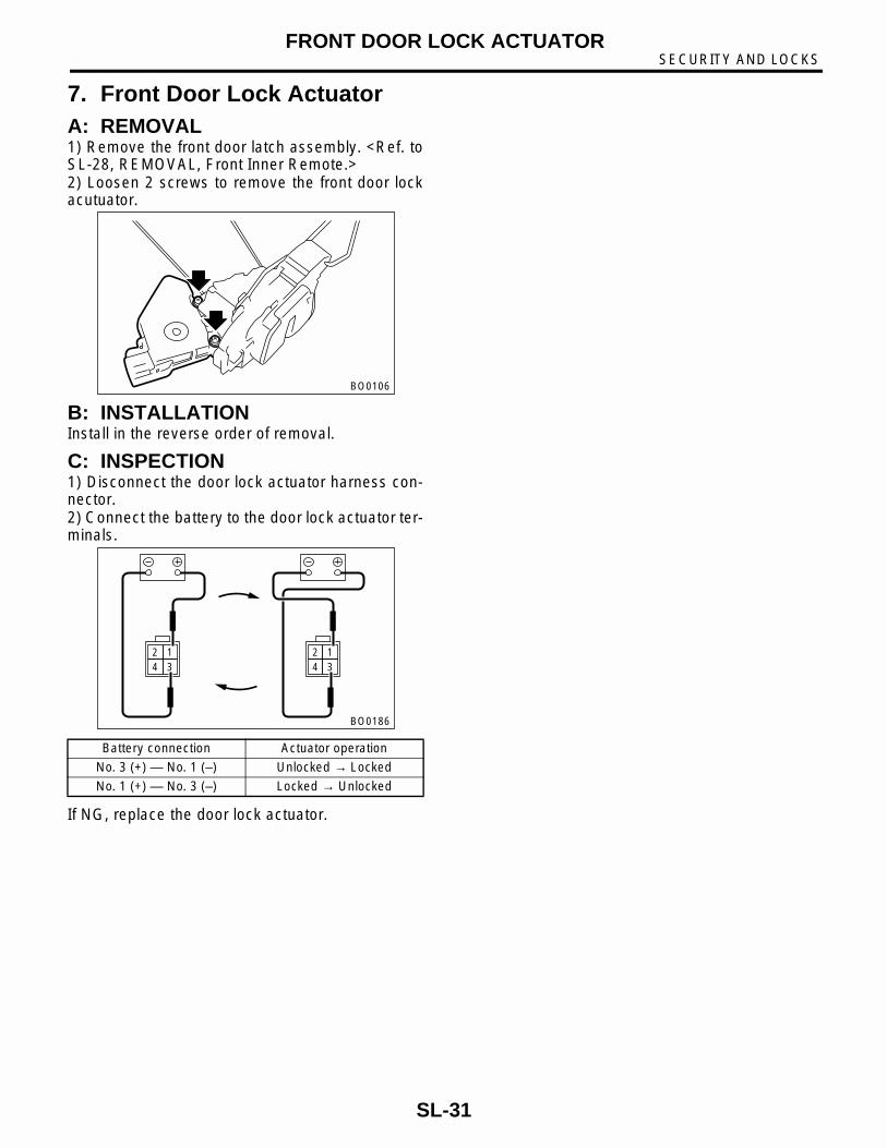
7. Front Door Lock ActuatorA: REMOVAL1) Remove the front door latch assembly. <Ref. toSL-28, REMOVAL, Front Inner Remote.>2) Loosen 2 screws to remove the front door lockacutuator.
B: INSTALLATIONInstall in the reverse order of removal.
C: INSPECTION1) Disconnect the door lock actuator harness con-nector.2) Connect the battery to the door lock actuator ter-minals.
If NG, replace the door lock actuator.
Battery connection Actuator operation
No. 3 (+) — No. 1 (–) Unlocked → Locked
No. 1 (+) — No. 3 (–) Locked → Unlocked
BO0106
2 14 3
2 14 3
BO0186
SL-31

SECURITY AND LOCKSREAR INNER REMOTE
8. Rear Inner RemoteA: REMOVAL1) Remove the rear door trim. <Ref. to EI-21, RE-MOVAL, Rear Door Trim.>2) Remove the sealing cover. <Ref. to EB-16, RE-MOVAL, Rear Sealing Cover.>3) Remove screw and the two rod joints.4) Remove the inner remote.
B: INSTALLATIONInstall in the reverse order of removal.
CAUTION:Make sure the lock works properly after instal-lation.
C: INSPECTION1) Make sure the rod is not deformed.2) Make sure the lever and rod work smoothly.3) Make sure the child safety lock on rear doorswork properly, when applicable.
BO0108
SL-32

SECURITY AND LOCKSREAR OUTER HANDLE
9. Rear Outer HandleA: REMOVAL1) Remove the rear door trim. <Ref. to EI-21, RE-MOVAL, Rear Door Trim.>2) Remove the sealing cover. <Ref. to EB-16, RE-MOVAL, Rear Sealing Cover.>3) Remove the rear inner remote. <Ref. to SL-32,REMOVAL, Rear Inner Remote.>4) Remove the rear door latch assembly. <Ref. toSL-34, REMOVAL, Rear Door Latch Assembly.>5) Loosen 2 bolts and nut to remove rear outer han-dle.
CAUTION:Do not use excessive force to remove the door panel. This will deform it.
B: INSTALLATIONInstall in the reverse order of removal.
C: INSPECTION1) Make sure the rod is not deformed.2) Make sure the lever and rod work smoothly.
BO0111
SL-33

SECURITY AND LOCKSREAR DOOR LATCH ASSEMBLY
10.Rear Door Latch AssemblyA: REMOVAL1) Remove the rear door trim. <Ref. to EI-21, RE-MOVAL, Rear Door Trim.>2) Remove the sealing cover. <Ref. to EB-16, RE-MOVAL, Rear Sealing Cover.>3) Remove the rear inner remote. <Ref. to SL-32,REMOVAL, Rear Inner Remote.>4) Remove the 3 screws and bolt.
5) Disconnect the connector, and then remove therear door latch assembly.
B: INSTALLATIONInstall in the reverse order of removal.
CAUTION:Make sure the lock works properly after instal-lation.
C: INSPECTION1) Make sure the rod is not deformed.2) Make sure the lever and rod work smoothly.
BO0109
SL-34
SECURITY AND LOCKSREAR DOOR LOCK ACTUATOR
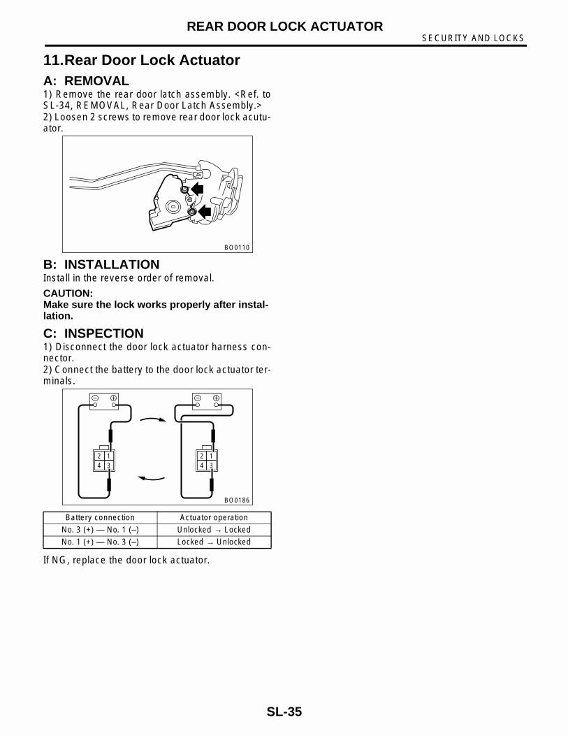
11.Rear Door Lock ActuatorA: REMOVAL1) Remove the rear door latch assembly. <Ref. toSL-34, REMOVAL, Rear Door Latch Assembly.>2) Loosen 2 screws to remove rear door lock acutu-ator.
B: INSTALLATIONInstall in the reverse order of removal.
CAUTION:Make sure the lock works properly after instal-lation.
C: INSPECTION1) Disconnect the door lock actuator harness con-nector.2) Connect the battery to the door lock actuator ter-minals.
If NG, replace the door lock actuator.
Battery connection Actuator operation
No. 3 (+) — No. 1 (–) Unlocked → Locked
No. 1 (+) — No. 3 (–) Locked → Unlocked
BO0110
2 14 3
2 14 3
BO0186
SL-35

SECURITY AND LOCKSREAR GATE OUTER HANDLE
12.Rear Gate Outer HandleA: REMOVAL1) Remove the rear gate trim. <Ref. to EI-34, RE-MOVAL, Rear Gate Trim.>2) Remove the rear gate latch assembly. <Ref. toSL-37, REMOVAL, Rear Gate Latch Assembly.>3) Loosen 2 nuts to remove rear gate outer handle.
B: INSTALLATIONInstall in the reverse order of removal.
C: INSPECTION1) Inspect the rod for deformation.2) Make sure the lever and rod move smoothly.
BO0114
SL-36

SECURITY AND LOCKSREAR GATE LATCH ASSEMBLY
13.Rear Gate Latch AssemblyA: REMOVAL1) Remove the rear gate trim. <Ref. to EI-34, RE-MOVAL, Rear Gate Trim.>2) Remove the rear gate key cylinder rod clamp.3) Remove the 3 bolts.
4) Disconnect connectors, and then remove reargate latch assembly.
B: INSTALLATIONInstall in the reverse order of removal.
CAUTION:Make sure the lock works properly after instal-lation.
C: INSPECTION1) Make sure the rod is not deformed.2) Make sure the lever and rod work smoothly.
BO0112
SL-37

SECURITY AND LOCKSREAR GATE LATCH LOCK ACTUATOR
14.Rear Gate Latch Lock Actua-tor
A: REMOVAL1) Remove the rear gate latch assembly. <Ref. toSL-37, REMOVAL, Rear Gate Latch Assembly.>2) Loosen 2 screws to remove rear gate lock actu-ator.
B: INSTALLATIONInstall in the reverse order of removal.
C: INSPECTION1) Disconnect the door lock actuator harness con-nector.2) Connect the battery to the door lock actuator ter-minals.
If NG, replace the rear gate latch lock actuator.
Battery connection Actuator operation
No. 1 (+) — No. 2 (–) Unlocked → Locked
No. 2 (+) — No. 1 (–) Locked → Unlocked
BO0113
2 1 2 1
BO0191
SL-38
SECURITY AND LOCKSTRUNK LID LOCK ASSEMBLY
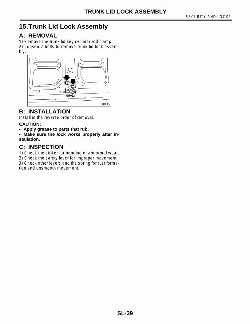
15.Trunk Lid Lock AssemblyA: REMOVAL1) Remove the trunk lid key cylinder rod clamp.2) Loosen 2 bolts to remove trunk lid lock assem-bly.
B: INSTALLATIONInstall in the reverse order of removal.
CAUTION:• Apply grease to parts that rub.• Make sure the lock works properly after in-stallation.
C: INSPECTION1) Check the striker for bending or abnormal wear.2) Check the safety lever for improper movement.3) Check other levers and the spring for rust forma-tion and unsmooth movement.
BO0115
SL-39

SECURITY AND LOCKSFRONT HOOD LOCK ASSEMBLY
16.Front Hood Lock AssemblyA: REMOVAL1) Open the hood.2) Remove the bolt. Remove the hood lock assem-bly.3) Remove the release cable from the lock assem-bly.
B: INSTALLATIONInstall in the reverse order of removal.
CAUTION:• Apply grease to parts that rub.• Make sure the release cable works properlyafter installation.
C: ADJUSTMENTLoosen the bolt. Adjust the lock assembly whilemoving it up and down.
D: INSPECTION1) Check the striker for bending or abnormal wear.2) Check the safety lever for improper movement.3) Check other levers and the spring for rust forma-tion and unsmooth movement.
BO0187
BO0188
SL-40

SECURITY AND LOCKSREMOTE OPENERS
17.Remote OpenersA: REMOVAL1. HOOD OPENER1) Remove the release cable from the hood lock.2) Remove the bolt. Remove the opener lever.
2. TRUNK LID OPENER1) Remove the rear seat. <Ref. to SE-11, REMOV-AL, Rear Seat.>2) Remove the center pillar lower trim and side sillcover on the passenger side. Remove the rear pil-lar lower trim. Pull back the floor mat. Remove theclip holding the cable. 3) Remove the bolt. Remove the opener pull han-dle.
4) Remove the cable from the opener pull handle.5) Remove the striker from the trunk lid.6) Remove the cable from the striker.
3. FUEL FLAP OPENER1) Remove the rear seat. <Ref. to SE-11, REMOV-AL, Rear Seat.>2) Remove the center pillar lower trim and side sillcover on the passenger side. Remove the rear pil-lar lower trim. Pull back the floor mat. Remove theclip holding the cable.3) Remove the bolt. Remove the opener pull han-dle.
4) Remove the cable from the opener pull handle.5) Remove the right rear quarter trim. <Ref. to EI-30, REMOVAL, Rear Quarter Trim.>6) Rotate the fuel lock inside the quarter panel toleft and remove.
B: INSTALLATION1. HOOD OPENERInstall in the reverse order of removal.
2. TRUNK LID OPENERInstall in the reverse order of removal.
3. FUEL FLAP OPENERInstall in the reverse order of removal.
C: INSPECTIONMake sure the fuel flap opens and closes smoothly.
B5M0751
G5M0151
G5M0147
G5M0151
B5M1067
SL-41

SECURITY AND LOCKSIGNITION KEY LOCK
18.Ignition Key LockA: REPLACEMENT1) Remove the battery ground cable.2) Remove the steering column. <Ref. to PS-30,REMOVAL, Tilt Steering Column.>3) Secure the steering column in a vise. Removethe bolt with a drill.
4) Remove the ignition key lock.5) Use a new torn bolt. Tighten the torn bolt to theend of the thread.
B: INSPECTION1) Remove the instrument panel lower cover.2) Remove the lower column cover.3) Unfasten the holddown clip which secures theharness and disconnect the connector of the igni-tion switch from the body harness.4) Turn the ignition key plate to each position andcheck the continuity between the terminals of theignition connector.
If NG, replace the ignition switch.
Switch position Tester connection Specified condi-tion
LOCK
ACC No. 1 — No. 2 Continuity
ON No. 1 — No. 2 — No. 4
Continuity
ST No. 1 — No. 3 — No. 4
Continuity
B5M1061
S6M0162A
SL-42

SECURITY AND LOCKSKEY LOCK CYLINDERS
19.Key Lock CylindersA: REPLACEMENT1. FRONT DOOR1) Remove the door trim. <Ref. to EI-20, REMOV-AL, Front Door Trim.>2) Pull back the sealing cover.3) Move front door glass downward.4) Remove the rod clamp. Remove the bolt. Re-place the key cylinder.
2. TRUNK LID1) Remove the trunk trim. <Ref. to EI-36, REMOV-AL, Trunk Trim.>2) Remove the rod clamp. Remove the lock plate.Replace the key cylinder.
3. REAR GATE1) Remove the rear gate trim. <Ref. to EI-34, RE-MOVAL, Rear Gate Trim.>2) Remove the rod clamp. Remove the lock plate.Replace the key cylinder.
BO0189
B5M1085
BO0190
SL-43

SECURITY AND LOCKSIMMOBILIZER CONTROL MODULE
20.Immobilizer Control ModuleA: REMOVALNOTE:The following positions for removal and installationare for LHD models. The positions for RHD modelsare symmetrically opposite.1) Disconnect GND cable from battery.2) Remove instrument panel lower cover. <Ref. toEI-25, REMOVAL, Instrument Panel Assembly.>3) Disconnect connector from immobilizer controlmodule.4) Remove immobilizer control module.
B: INSTALLATIONInstall in the reverse order of removal.
BO0193
SL-44

SECURITY AND LOCKSIMMOBILIZER ANTENNA
21.Immobilizer AntennaA: REMOVAL1) Disconnect GND cable from battery.2) Remove instrument panel lower cover. <Ref. toEI-25, REMOVAL, Instrument Panel Assembly.>3) Remove screws, separate upper column coverand lower column cover.
4) Disconnect immobilizer antenna connector (A)from immobilizer control module.5) Remove immobilizer antenna (B).
B: INSTALLATIONInstall in the reverse order of removal.
B6M1184
H6M0710A
SL-45
SECURITY AND LOCKSKEYLESS ENTRY CONTROL MODULE
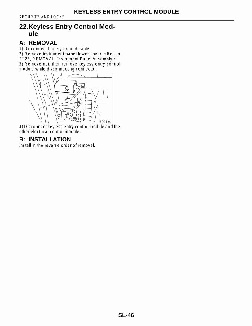
22.Keyless Entry Control Mod-ule
A: REMOVAL1) Disconnect battery ground cable.2) Remove instrument panel lower cover. <Ref. toEI-25, REMOVAL, Instrument Panel Assembly.>3) Remove nut, then remove keyless entry controlmodule while disconnecting connector.
4) Disconnect keyless entry control module and theother electrical control module.
B: INSTALLATIONInstall in the reverse order of removal.
BO0194
SL-46

SECURITY AND LOCKSKEYLESS TRANSMITTER
23.Keyless TransmitterA: REMOVAL1. TRANSMITTER BATTERYRemove battery from transmitter.
NOTE:To prevent static electricity damage to transmitterprinted circuit board, touch steel area of buildingwith hand to discharge static electricity carried onbody or clothes before disassembling transmitter.
B: INSTALLATION1. TRANSMITTER BATTERYInstall in the reverse order of removal.
C: INSPECTION1. TRANSMITTER BATTERY1) Measure voltage between battery (+) terminaland (–) terminal.
NOTE:• Battery discharge occurs during measurement.Complete measurement within 5 seconds.• During battery voltage measurement, voltagefalls more than 1.8 volts in 3 seconds period.
If NG, replace the battery. (Use CR1620 or equiva-lent.)
D: REPLACEMENT1. TRANSMITTER REGISTRATION
NOTE:A maximum of 3 transmitters can be registered foreach individual vehicle.1) Remove the side sill cover at the driver's side,then connect the registration connectors at thefront pillar lower section.2) Unlock the door lock.3) Press the OPEN button of the transmitter to beregistered. Immediately afterwards, press theLOCK button.4) The door lock will automatically lock and unlockin sequence. This indicates the completion of trans-mitter registration for the first transmitter.5) If registration of a second transmitter is now to becarried out, press the OPEN button of that transmit-ter. Immediately afterwards, press the LOCK but-ton.6) The door lock will automatically lock and unlockin sequence. This indicates the completion of trans-mitter registration for the second transmitter.7) Disconnect the registration connectors after thecompletion of all registration operations. After con-firming the operation of the door lock using thenewly registered transmitter(s), reinstall the side sillcover at the driver's side.
Tester connectionVoltage (V)
(+) (–)
Battery (+) termi-nal
Battery (–) termi-nal
2.5 — 3.0
B5M1182
Resistance 300
BO0195
SL-47

SECURITY AND LOCKSKEYLESS TRANSMITTER
SL-48