Nios Hardware Development Tutorial for the Nios Development ...

September 2002, ver. 1.2 Application Note 188
Custom Instructionsfor the Nios Embedded
Processor
Introduction With the Altera® Nios® embedded processor, system designers can accelerate time-critical software algorithms by adding custom instructions to the Nios instruction set. System designers can use custom instructions to implement complex processing tasks in single-cycle (combinatorial) and multi-cycle (sequential) operations. Additionally, user-added custom instruction logic can access memory and/or logic outside of the Nios system.
Using custom instructions, system designers can reduce a complex sequence of standard instructions to a single instruction implemented in hardware. System designers can use this feature for a variety of applications, e.g., to optimize software inner loops for digital signal processing (DSP), packet header processing, and computation-intensive applications. The Nios CPU configuration wizard, which is accessed from the SOPC Builder, provides a graphical user interface that system designers can use to add up to five custom instructions to the Nios processor.
This application note describes the Nios custom instruction feature, provides a design example, and describes how to implement custom instructions.
Understanding Custom Instructions
With custom instructions, system designers can add custom-defined functionality to the Nios processor’s arithmetic logic unit (ALU) and instruction set (see Figure 1 on page 2). Custom instructions consist of two essential elements:
� Custom logic block—Hardware that performs the operation. The Nios processor can include up to five user-defined custom logic blocks. The blocks become part of the Nios microprocessor’s ALU.
� Software macro—Allows the system designer to access the custom logic through software code.
Altera Corporation 1
AN-188-1.2

AN 188: Custom Instructions for the Nios Embedded Processor
Figure 1. Adding Custom Logic to the Nios ALU
The custom logic block performs a user-defined operation (represented as op in the custom instruction table of the Nios configuration wizard) on the contents of two registers (Ra and Rb) and stores the result in Ra, for example, Ra <- Ra op Rb. You can design a custom instruction logic block to perform any function, as long as the logic block has the appropriate interface as described in this document. See “Hardware Interface” on page 3 for more details. See “Software Interface” on page 7 for information on accessing your custom instruction logic block from software.
The Nios configuration wizard integrates the custom logic blocks with the Nios processor’s ALU when building the Nios embedded processor (see Figure 2). The Nios configuration wizard also creates software macros in C/C++ and Assembly, providing software access to these custom logic blocks. You must provide the name of the macro. If the custom instruction is combinatorial, the number of clock cycles needed to perform the instruction is fixed at 1. If the custom instruction is sequential, you must provide the number of clock cycles.
Nios Embedded Processor
To FIFO, Memory, or Other Logic
+ -
&
<< >>
Out
A
A
NiosALU
B
BCustom Logic
2 Altera Corporation

AN 188: Custom Instructions for the Nios Embedded Processor
Figure 2. Custom Instructions Tab in the Nios Configuration Wizard
Hardware Interface
You can create custom logic blocks using the following formats:
� Verilog HDL� VHDL� EDIF netlist file� Quartus II Block Design File (.bdf)� Verilog Quartus Mapping File (.vqm)
Because the block connects directly to the ALU, it must provide an interface with predefined ports and names (see Figure 3). The Nios configuration wizard scans the custom logic blocks, searches for the required ports, and connects these ports to the ALU.
Altera Corporation 3

AN 188: Custom Instructions for the Nios Embedded Processor
Figure 3. Custom Logic Block Interface (32-Bit Nios Processor)
You can implement custom logic blocks using one or a combination of these four options:
� Combinatorial logic � Multi-cycle logic � Parameterization� User-defined ports
Combinatorial Logic Option
Using the combinatorial logic option, the custom logic block must complete the operation in a single clock cycle. Because the transaction takes one clock cycle to complete, the block only requires data ports, and does not require control signals (see Table 1).
1 If the block only requires one input port, use the dataa port.
Combinatorial
Optional FIFO, Memory, or Other Logic
Multi-Cycle
Parameterized
dataa
datab
clk
clk_en
reset
start
prefix
result
32
32
11
32
4 Altera Corporation

AN 188: Custom Instructions for the Nios Embedded Processor
Multi-Cycle Logic Option
For multi-cycle or sequential logic, the custom logic block must provide the data ports shown in Table 1 as well as control signal ports (see Table 2). These control signals provide status to the custom logic block and synchronize it with the Nios processor. When you add the custom instruction in the Nios configuration wizard, you must enter the number of clock cycles the block requires to perform the operation.
The CPU asserts start on the first clock cycle the operation executes when the ALU issues the custom instruction. At this time, dataa and datab hold valid values. The CPU waits for the required number of clock cycles specified in the Nios configuration wizard and then reads result.
Table 1. Ports for Combinatorial Custom Logic
Port Name Width (Bits) Direction Description
dataa CPU width Input Operand
datab CPU width Input Operand (optional)
result CPU width Output Result
Table 2. Additional Ports for Sequential Custom Logic
Port Name Width (Bits) Direction Description
clk 1 Input CPU master input clock, which is fed by the Nios system clock.
reset 1 Input CPU master asynchronous reset, which is fed by the Nios master reset. reset is only asserted when the Nios system is reset.
clk_en 1 Input Clock qualifier. The custom logic block should use the clk_en signal as a conventional clock qualifier signal and should ignore all rising clock edges when clk_en is not asserted.
start 1 Input Instructs the block to latch data and begin operation.
Altera Corporation 5

AN 188: Custom Instructions for the Nios Embedded Processor
6 Altera Corporation
Parameterization Option
You can use the optional 11-bit prefix port (see Table 3) to pass a parameter to the custom instruction. The prefix port uses the Nios PFX instruction to load the 11-bit K register before the custom instruction executes. The custom logic block receives the K register data upon execution of the custom instruction.
You can use the prefix port with either combinatorial or multi-cycle custom logic blocks. The interpretation of the prefix data is unspecified, so you can use it for a variety of purposes. In extreme cases, you can encode prefix to represent up to 2,048 different functions contained in a single custom instruction.
User-Defined Ports Option
Optional user-defined ports allow the custom instruction to interact with components outside of the Nios system. If the Nios configuration wizard does not recognize a port, it routes the port to the top level of the system module where external logic can access the signals.
Combining Options
Using a combination of multi-cycle ports, the prefix port, and user-defined ports, you can implement extremely versatile operations, including cases in which a custom instruction’s operation is dependent upon previous instances of the instruction. Example applications include:
� A custom multiply accumulate (MAC) instruction. The result of each multiplication is added to a running total. You can use multiple clock cycles to pipeline the function, increasing system performance as needed. The prefix port resets the MAC to zero (a value of zero in software corresponds to a logic low in hardware).
� A custom packet processing instruction. The custom instruction receives up to 64 bits of data using dataa and datab in parallel. Based on a command specified using prefix, the packet processing logic could operate on the 64-bit packet (e.g., mask bits in the header) and quickly inject the packet back into the data stream by outputting the result via a user-defined port. A system can perform bit-compare, bit-modify, and output-to-datastream (i.e., write-to-FIFO) operations in one or two clock cycles.
Table 3. Prefix Port
Port Name Width (Bits) Direction Description
prefix 11 Input Payload of the K register.

AN 188: Custom Instructions for the Nios Embedded Processor
Because the custom instruction logic is integrated with the Nios CPU, the design of the custom instruction directly affects the fMAX performance of the entire Nios CPU. You can pipeline the custom instruction logic so that it does not become a performance bottleneck in a Nios system.
Software Interface
After you integrate a custom logic block into the Nios processor’s ALU, you can access the custom logic through software. The Nios architecture includes five user-definable opcodes (see Table 4) with which you can access the custom logic block. You call these opcodes in software—written in C/C++ or Assembly—using macros.
As described earlier, the custom instruction takes the contents of two general-purpose registers (Ra and Rb) and performs an operation as defined by the custom logic block. The result of this operation is then stored in a general-purpose register (Ra).
The USR0 opcode is of type RR, which can use any of the general-purpose registers for Ra and Rb. USR1 through USR4 are type Rw opcodes, where Ra can be any of the general-purpose registers. However, Rb must be the %r0 register.
f For more information on opcodes and their usage, refer to the Nios 16-Bit Programmer’s Reference Manual and the Nios 32-Bit Programmer’s Reference Manual.
When writing C/C++ code, the register usage is transparent, because the compiler automatically chooses the registers. However, in Assembly, you must indicate which registers are used for a particular operation.
The Nios configuration wizard automatically builds the macro after you add the custom instruction. The wizard supports macro naming for ease of use and readability of your software code.
Table 4. User Opcode, Type & Format
Opcode Type Format
USR0 RR Ra <- Ra op Rb
USR1 Rw Ra <- Ra op %r0
USR2 Rw Ra <- Ra op %r0
USR3 Rw Ra <- Ra op %r0
USR4 Rw Ra <- Ra op %r0
Altera Corporation 7

AN 188: Custom Instructions for the Nios Embedded Processor
Using Custom Instructions in C/C++
When using custom instructions in C/C++, you access the custom instruction with a function call. Your Nios system header file (excalibur.h), which the SOPC Builder generates, includes the C/C++ macro definition. There are two different C/C++ macros, one for use with prefix:
nm_<name>_pfx(prefix, dataa, datab)
and one for use without prefix:
nm_<name>(dataa, datab)
If your custom instruction uses the prefix port, the only valid input to prefix is an immediate value of 11 bits or less. If the C/C++ macro does not pass a value for prefix, the custom logic’s prefix port is loaded with zero. Figure 4 shows an example using a custom instruction (my_cust_inst) with and without a prefix.
Figure 4. C Code Using a Custom Instruction
int main(void){unsigned short a = 4660;unsigned short b = 17185;unsigned int return_value = 0;unsigned int return_value_1 = 0;
printf ("\n\nWill call the My_Cust_Inst function ...\n");
return_value = nm_my_cust_inst(a, b); //If a prefix is not given, the//value is 0x000
return_value_1 = nm_my_cust_inst_pfx(1, a, b);
printf("After the call, return_value = \n", return_value);printf("After the call, return_value_1 = %d \n", return_value_1);
return (0);}
8 Altera Corporation

AN 188: Custom Instructions for the Nios Embedded Processor
Using Custom Instructions in Assembly
When using custom instruction in Assembly, you can use either the Assembly macro or the opcode to call the custom instruction. To use the macro, include the Nios header file (excalibur.h), which the SOPC Builder generates. If you use prefix, the PFX instruction must precede the custom instruction macro, otherwise zero is loaded into the prefix port. Figure 5 shows an example using a custom instruction (my_cust_inst) with the PFX instruction. When using an Rw opcode, the opcode automatically loads the %r0 register for the datab port.
Figure 5. Assembly Code Using A Custom Instruction
LD %r1,[%L6] ; Load word at [%L6] into %r1LD %r0,[%L2] ; Load word at [%L2] into %r0PFX 1 ; Only needed if using prefixnm_my_cust_inst %r1 ; Macro calling a Rw opcode, r1 <- r1 “OP” r0ST [%L4],%r1 ; %L4 is the pointer, %r1 is stored
Design Example
The following example, which is an excerpt of a reference design provided with the Nios embedded processor, shows the benefits of using custom instructions versus a software-only implementation. The design uses a simple four-function floating-point unit (FPU) created in hardware as a custom instruction. The FPU implements the signed multiply, multiply with negate, absolute value, and negate floating-point operations. The prefix port specifies the different operations of the FPU.
All four functions are compared with their respective software implementation. A timer measures the clock cycles required for each operation. Sample code for the multiplication is provided in Figure 6. For the complete hardware and software design used in this example, refer to the reference design in the <Nios installation directory>\tutorials\CI_Tutorial\Cust_Inst_Example1 directory.
Altera Corporation 9

AN 188: Custom Instructions for the Nios Embedded Processor
Figure 6. Multiplication with Custom Instructions
/******************//* Multiplication *//******************/
a=-32.57;b=300.84;
dwStartTick=GetTickCount(); /* record start time*/
res_a=a*b;
lTicksUsed=GetTickCount(); /* record end time */
printf("\nFor Nios software implementation:");printf("\nValue of a is: %f", a);printf("\nValue of b is: %f", b);printf("\nValue of a*b is: %f", res_a);
CheckTimeStamp (dwStartTick, lTicksUsed);
our_dwStartTick=GetTickCount(); /* record start time*/
res_a = nm_fpu_pfx(2, a, b)
our_lTicksUsed=GetTickCount(); /* record end time */
printf("\nFor the floating point module: ");printf("\nValue of a is: %f", a);printf("\nValue of b is: %f", b);printf("\nValue of a*b is: %f", res_a);
CheckTimeStamp (our_dwStartTick, our_lTicksUsed);
Table 5 compares the performance of the custom instruction versus a software-only implementation. The custom instruction increases the performance by as much as two orders of magnitude over the software-only implementations.
10 Altera Corporation

AN 188: Custom Instructions for the Nios Embedded Processor
Note:(1) These performance calculations are compiler-dependant. They were taken using
the Cygnus compiler included in Version 2.1 of the Nios embedded processor.
Additionally, custom instructions reduce the software code needed to perform the operations:
� Custom instruction—200 bytes� Software-only—4 KBytes
In this example, a standard math library performs the software implementation for floating-point math. However, there are many custom applications for which a predefined library is not available. In these cases, you must create the functionality in C/C++ or Assembly, further increasing the complexity of the software code.
By using custom instructions, you only need to call the software macro to interface with hardware that completes the task, reducing both the complexity and size of the software code.
Implementing Custom Instructions
This section describes the process of implementing a custom instruction and includes the following steps:
� “Create a Custom Logic Block” on page 12� “Instantiate the Custom Instruction” on page 14� “Create Software Code Using Macros” on page 18
Table 5. Custom Instruction vs. Software-Only Performance Comparison (1)
Floating-Point Operation CPU Clock Cycles Speed Increase
Software Library
Custom Instruction (FPU)
Multiplication a × b 2,874 19 151.26
Multiply and Negate -(a × b) 3,147 19 165.63
Absolute |a| 1,769 18 98.28
Negate -(a) 284 19 14.95
Altera Corporation 11

AN 188: Custom Instructions for the Nios Embedded Processor
Create a Custom Logic Block
To begin, create a logic block that performs the functionality you want. You control the design and operation of the custom logic block, however, you must follow these guidelines:
� File Format� Port Naming� Port Operation� Multi-Cycle Signal Timing
File Format
When creating your logic block, you must use one of the following file formats:
� Verilog HDL� VHDL� EDIF netlist file� Quartus II .bdf� .vqm
1 If you black box design file(s), make sure to include the design file(s) in your Quartus II project.
Port Naming
When designing the logic block, you must include all of the required ports for the type of operation the block will perform (i.e., combinatorial or multi-cycle). Table 6 shows the required ports for each type of operation.
1 You must use these predefined port names so that the ports connect to the proper interface.
Table 6. Custom Instruction Ports
Port Width (Bits) Direction Combinatorial Multi-Cycle
dataa CPU width Input Required Required
datab CPU width Input Optional Optional
result CPU width Output Required Required
clk 1 Input – Required
reset 1 Input – Required
clk_en 1 Input – Required
start 1 Input – Required
prefix 11 Input Optional Optional
12 Altera Corporation

AN 188: Custom Instructions for the Nios Embedded Processor
The ports your block requires depend on whether you implement combinatorial or multi-cycle logic. Use combinatorial logic if the required operation can execute in a single CPU clock cycle. If the logic block cannot meet system frequency requirements for a single clock cycle or if is intrinsically a multi-cycle operation, you can pipeline the block. In these cases, you must use multi-cycle logic.
1 Adding custom logic blocks to the Nios ALU can affect the system frequency. Even if the custom logic block meets the system frequency requirements as standalone block, when you place it in the Nios system, changes in place and route may affect the performance.
Port Operation
You should design your logic block so that the ports operate as described below:
� For combinatorial logic, the CPU presents the data from the dataa and datab ports for execution on the rising edge of the CPU clock. The CPU reads the result port on the following rising edge of the CPU clock.
� For multi-cycle logic, the CPU asserts the start port on the first clock cycle of execution when the custom instruction issues through the ALU. At this time, dataa and datab have valid values. For all subsequent clock cycles, dataa and datab have undefined values. The CPU waits for the required number of clock cycles specified in the Nios configuration wizard for the custom instruction, and then reads the result port. See Figure 7.
� The Nios system clock feeds the block’s clk port, and the Nios master reset feeds the reset port. reset is asserted only when the whole Nios system is reset, e.g., during a watchdog timer time out. The logic block should use the clk_en signal as a conventional clock-qualifier signal and should ignore all clock rising edges during which clk_en is deasserted.
� You can use the optional prefix port with either combinatorial or multi-cycle logic; the interpretation of the 11-bit prefix data is not specified. The prefix port has a valid value on the first clock cycle of the execution when the custom instruction issues through the ALU. For all subsequent clock cycles, prefix has an undefined value.
Altera Corporation 13

AN 188: Custom Instructions for the Nios Embedded Processor
� You can add other ports to your logic block, which allows your custom logic block to access logic that is external to the Nios CPU. Any ports that are not recognized by the Nios configuration wizard are routed to the top level of the Nios system module. These ports are labeled export.
Multi-Cycle Signal Timing
Before instantiating your logic block, you must determine the number of CPU clock cycles your block requires. Combinatorial logic requires one clock cycle. For multi-cycle logic, you can simulate the logic block to verify the required number of clock cycles. For example, Figure 7 shows a logic block that uses five clock cycles. The CPU executes the custom instruction on the T0 clock edge, asserting the start bit and providing valid data for the next clock edge (T1). Five clock cycles later, the custom instruction provides a valid result. If you were instantiating the logic block in this example, you would specify five clock cycles in the Nios wizard.
Figure 7. Multi-Cycle Timing Example (5 CPU Clock Cycles)
Instantiate the Custom Instruction
You use the SOPC Builder in the Quartus II software to create a Nios embedded processor (CPU), configure system peripherals, and connect these elements to make a Nios system module. When you add a Nios CPU to the SOPC Builder, the Nios configuration wizard displays.
f For detailed instructions on creating a Nios design, including using the SOPC Builder and adding a Nios CPU, refer to the Nios Tutorial.
clk
clk_en
start
reset
dataa
datab
prefix
result
VALID
VALID
VALID
VALID
T0 T1 T2 T3 T4 T5
14 Altera Corporation

AN 188: Custom Instructions for the Nios Embedded Processor
Perform the following steps to add a custom instruction to the CPU.
1. Turn on Enable advanced configuration controls in the Architecture tab. See Figure 8.
Figure 8. Nios CPU Architecture Tab
2. Click the Custom Instructions tab.
3. Select the opcode (USR0 through USR4) that you want to use for the custom instruction.
4. Click Import. See Figure 9. The Interface to User Logic displays.
Figure 9. Nios CPU Custom Instructions Tab
5. Click Add under Design Files. See Figure 10.
Turn on the Enable advanced configuration controls option
Import Button
Select the opcode
Altera Corporation 15

AN 188: Custom Instructions for the Nios Embedded Processor
6. Browse to the directory in which you saved the design file(s) for your logic block.
7. Select all of the logic block design files and click Open.
8. Enter the name of logic block’s top-level module in the Top module name box. See Figure 10.
9. Click Populate Port Table. The wizard scans the files and imports the port information. The ports are displayed under Port Information. See Figure 10.
1 If the wizard does not scan the files correctly, you can manually enter the port names, widths, directions, and types.
Figure 10. Interface to User Logic
10. If your logic block has a different file format than your Nios system module, click the Instantiation tab. See Figure 11 on page 17.
Logic block design files
Imported port information
Populate Port Table button
Base macro name
Add button
16 Altera Corporation

AN 188: Custom Instructions for the Nios Embedded Processor
11. Select Instantiate as Black Box. See Figure 11.
1 The Instantiate as Black Box option is turned on automatically if your design files are .bdf, EDIF Input Files (.edf), or .vqm.
Figure 11. Instantiation as Black Box
12. Click Add to System. You are returned to the Nios configuration wizard Custom Instruction tab.
13. Enter the base name that you would like to use to call your custom instruction in C/C++ or Assembly in the macro Name box. The wizard inputs the first four letters of the top-level module by default. The actual macro name will be nm_<base name>. See Figure 12.
1 The wizard makes all macro names lower case.
14. Enter the number of clock cycles required to perform the operation in the Cycle Count box. See Figure 12.
Altera Corporation 17

AN 188: Custom Instructions for the Nios Embedded Processor
Figure 12. Macro Name & Clock Cycles
15. Repeat steps 3 through 14 for any additional custom instructions.
16. Click Finish when you are finished adding custom instructions.
17. Generate your Nios system module.
Create Software Code Using Macros
When you generate your Nios system module, the SOPC Builder creates software macros that you can use in your software code. The macros have the prefix nm_, which stands for Nios macro. The following sections describe how to use these macros in your C/C++ or Assembly code.
Using Macros in C/C++
For C/C++, you use the macros as a function call. Before using the macro, you must include the file excalibur.h, which is created by the SOPC Builder, in your code. Figure 13 shows an example macro the SOPC Builder created for a custom instruction.
Figure 13. C/C++ Example Macro
#define nm_fpu(_x,_y) ({\int __x = (_x), __y = (_y);\asm volatile("usr0 %0,%2 ; does fpu" \: "=r" (__x) \: "0" (__x), "r" (__y));\__x;\})
Base macro name
Enter the clock cycles
18 Altera Corporation

AN 188: Custom Instructions for the Nios Embedded Processor
When the SOPC Builder creates the macro, it assigns the inputs and outputs to type int (integer). If the inputs and outputs are not integers, you can manually edit the macro in the excalibur.h file to change int to another type (e.g., float). Alternatively, you can use type casting, which you would perform on the macro inputs and outputs. Figure 14 shows an example in which a macro takes in a signal of type float and changes it to type int (and vice versa) without changing any of the data bits.
Figure 14. Changing Signal Types
#define take_float_as_int32(x) (*((int *)(&(x))))#define take_int32_as_float(i) (*((float *)(&(i))))
When including a macro in your code, use the following format:
result = nm_<name>(dataa, datab);
If you only want to use one input port, leave out the datab input:
result = nm_<name>(dataa);
If you are using the prefix port, the SOPC Builder creates a second macro with the suffix _pfx. The only valid input for prefix is an immediate value, which is a literal constant from 0 to 2,047 (11-bits). You must enter this value directly into the macro; it cannot be defined previously. Figure 15 provides an example macro with a prefix.
Altera Corporation 19

AN 188: Custom Instructions for the Nios Embedded Processor
Figure 15. C/C++ Example Macro with Prefix
#define nm_fpu_pfx(_p,_x,_y) ({\int __x = (_x), __y = (_y);\asm volatile("pfx " #_p "\n\tusr0 %0,%2 ; does fpu" \: "=r" (__x) \: "0" (__x), "r" (__y));\__x;\})
When including a macro with a prefix in your code, use the following format:
result = nm_<name>_pfx(prefix, dataa, datab);
or
result = nm_<name>_pfx(prefix, dataa);
If your custom instruction has a prefix port but you do not want to use it, you should use the format for the non-prefix macro. In this case, an 11-bit zero is provided to the prefix port of the custom instruction operation. This scenario is useful for situations in which your default prefix is zero because you do not have to load the prefix register before your custom instruction executes.
Using Macros in Assembly
In Assembly, you can call your custom instruction using a macro or an opcode. To use the macro, you must include the excalibur.s file, which is created by the SOPC Builder, in your code.
You assign the opcode (USR0 through USR4) when you instantiate the custom instruction (refer to “Instantiate the Custom Instruction” on page 14). The macro calls the associated USR opcode and it is used in the same manner as the opcode.
For USR0, which is of type RR, you can input any of the 32 general-purpose registers for %Ra and %Rb. The resulting value is stored in the first register, %Ra. The format to use is:
nm_<name> %Ra %Rb
20 Altera Corporation
AN 188: Custom Instructions for the Nios Embedded Processor
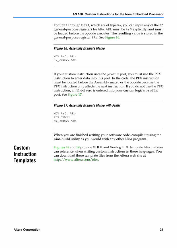
For USR1 through USR4, which are of type Rw, you can input any of the 32 general-purpose registers for %Ra. %Rb must be %r0 explicitly, and must be loaded before the opcode executes. The resulting value is stored in the general-purpose register %Ra. See Figure 16.
Figure 16. Assembly Example Macro
MOV %r0, %Rbnm_<name> %Ra
If your custom instruction uses the prefix port, you must use the PFX instruction to enter data into this port. In the code, the PFX instruction must be located before the Assembly macro or the opcode because the PFX instruction only affects the next instruction. If you do not use the PFX instruction, an 11-bit zero is entered into your custom logic’s prefix port. See Figure 17.
Figure 17. Assembly Example Macro with Prefix
MOV %r0, %RbPFX IMM11nm_<name> %Ra
When you are finished writing your software code, compile it using the nios-build utility as you would with any other Nios program.
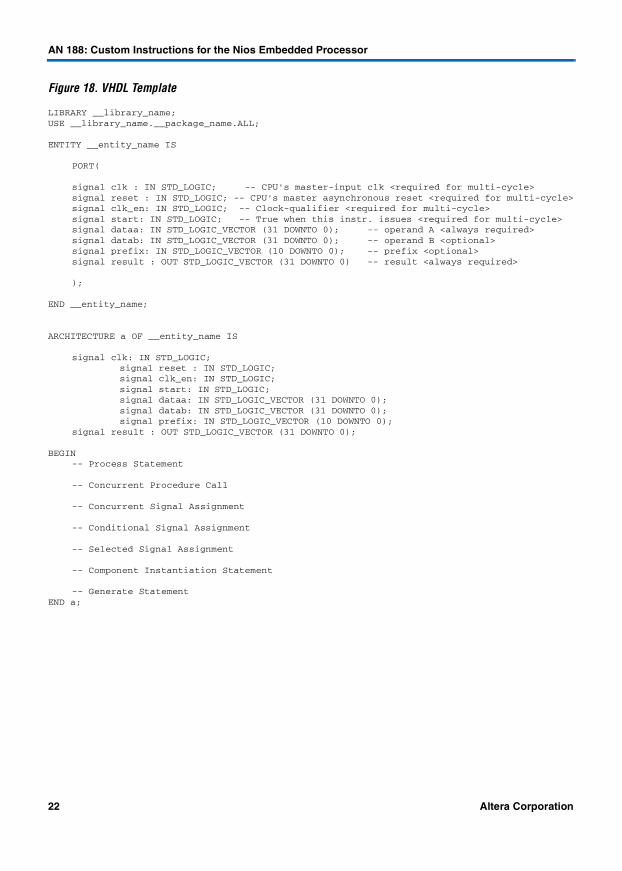
Custom Instruction Templates
Figures 18 and 19 provide VHDL and Verilog HDL template files that you can reference when writing custom instructions in these languages. You can download these template files from the Altera web site at http://www.altera.com/nios.
Altera Corporation 21
AN 188: Custom Instructions for the Nios Embedded Processor
Figure 18. VHDL Template
LIBRARY __library_name;USE __library_name.__package_name.ALL;
ENTITY __entity_name IS
PORT(
signal clk : IN STD_LOGIC; -- CPU's master-input clk <required for multi-cycle>signal reset : IN STD_LOGIC; -- CPU's master asynchronous reset <required for multi-cycle>signal clk_en: IN STD_LOGIC; -- Clock-qualifier <required for multi-cycle>signal start: IN STD_LOGIC; -- True when this instr. issues <required for multi-cycle>signal dataa: IN STD_LOGIC_VECTOR (31 DOWNTO 0); -- operand A <always required>signal datab: IN STD_LOGIC_VECTOR (31 DOWNTO 0); -- operand B <optional>signal prefix: IN STD_LOGIC_VECTOR (10 DOWNTO 0); -- prefix <optional>signal result : OUT STD_LOGIC_VECTOR (31 DOWNTO 0) -- result <always required>
);
END __entity_name;
ARCHITECTURE a OF __entity_name IS
signal clk: IN STD_LOGIC;signal reset : IN STD_LOGIC;signal clk_en: IN STD_LOGIC;signal start: IN STD_LOGIC;signal dataa: IN STD_LOGIC_VECTOR (31 DOWNTO 0);signal datab: IN STD_LOGIC_VECTOR (31 DOWNTO 0);signal prefix: IN STD_LOGIC_VECTOR (10 DOWNTO 0);
signal result : OUT STD_LOGIC_VECTOR (31 DOWNTO 0);
BEGIN-- Process Statement
-- Concurrent Procedure Call
-- Concurrent Signal Assignment
-- Conditional Signal Assignment
-- Selected Signal Assignment
-- Component Instantiation Statement
-- Generate StatementEND a;
22 Altera Corporation

AN 188: Custom Instructions for the Nios Embedded Processor
Figure 19. Verilog HDL Template
module __module_name(clk, // CPU's master-input clk <required for multi-cycle>reset, // CPU's master asynchronous reset <required for multi-cycle>clk_en, // Clock-qualifier <required for multi-cycle>start, // True when this instr. issues <required for multi-cycle>dataa, // operand A <always required>datab, // operand B <optional>prefix, // prefix <optional>result // result <always required>);
input clk;input reset;input clk_en;input start;input [31:0] dataa;input [31:0] datab;input [10:0] prefix;
output [31:0]result;
// Port Declaration
// Wire Declaration
// Integer Declaration
// Concurrent Assignment
// Always Construct
endmodule
Conclusion Custom instructions are a powerful tool that allow you to customize the Nios embedded processor for a particular application. This customization can increase the performance of Nios systems dramatically, while reducing the size and complexity of the software.
Documentation Feedback
Altera values your feedback. If you would like to provide feedback on this document—e.g., clarification requests, inaccuracies, or inconsistencies—send e-mail to [email protected].
Altera Corporation 23

AN 188: Custom Instructions for the Nios Embedded Processor
24 Altera Corporation
101 Innovation DriveSan Jose, CA 95134(408) 544-7000http://www.altera.comApplications Hotline:(800) 800-EPLDLiterature Services:[email protected]
Copyright 2002 Altera Corporation. Altera, The Programmable Solutions Company, the stylized Altera logo,specific device designations, and all other words and logos that are identified as trademarks and/or servicemarks are, unless noted otherwise, the trademarks and service marks of Altera Corporation in the U.S. andother countries. All other product or service names are the property of their respective holders. Altera productsare protected under numerous U.S. and foreign patents and pending applications, mask work rights, andcopyrights. Altera warrants performance of its semiconductor products to currentspecifications in accordance with Altera’s standard warranty, but reserves the right tomake changes to any products and services at any time without notice. Altera assumes noresponsibility or liability arising out of the application or use of any information, product,or service described herein except as expressly agreed to in writing by Altera Corporation.Altera customers are advised to obtain the latest version of device specifications beforerelying on any published information and before placing orders for products or services.All rights reserved.