200 AC/DCTRANSTIG...SERVICE MANUAL TRANSTIG 200 AC/DC January 17, 2008 1-1 1.01 Arc Welding Hazards...
128
200 Amp 240 V 1 50 60 Hz INVERTER TRANSTIG ® INVERTER ARC WELDER 200 AC/DC Service Manual Revision No: AA Issue Date: January 17, 2008 Manual No.: 0-5001 Operating Features:
Transcript of 200 AC/DCTRANSTIG...SERVICE MANUAL TRANSTIG 200 AC/DC January 17, 2008 1-1 1.01 Arc Welding Hazards...

200Amp
240V
1 5060
HzINVERTER
TRANSTIG®
INVERTER ARC WELDER
200 AC/DC
Service ManualRevision No: AA Issue Date: January 17, 2008 Manual No.: 0-5001
Operating Features:

WE APPRECIATE YOUR BUSINESS!Congratulations on your new CIGWELD product. We are proud tohave you as our customer and will strive to provide you with thebest service and reliability in the industry. This product is backedby our extensive warranty and world-wide service network. To locateyour nearest distributor or service agency please call+61-3-9474-7400, or visit us on the web at www.cigweld.com.au.
This Operating Manual has been designed to instruct you on thecorrect use and operation of your CIGWELD product. Yoursatisfaction with this product and its safe operation is our ultimateconcern. Therefore please take the time to read the entire manual,especially the Safety Precautions. They will help you to avoidpotential hazards that may exist when working with this product.
YOU ARE IN GOOD COMPANY!The Brand of Choice for Contractors and Fabricators Worldwide.
CIGWELD is a Global Brand of Arc Welding Products forThermadyne Industries Inc. We manufacture and supply to majorwelding industry sectors worldwide including; Manufacturing,Construction, Mining, Automotive, Aerospace, Engineering, Ruraland DIY/Hobbyist.
We distinguish ourselves from our competition through market-leading, dependable products that have stood the test of time. Wepride ourselves on technical innovation, competitive prices,excellent delivery, superior customer service and technical support,together with excellence in sales and marketing expertise.
Above all, we are committed to develop technologically advancedproducts to achieve a safer working environment for industryoperators.

WARNINGS
Read and understand this entire Manual and your employer’s safety practices before installing,operating, or servicing the equipment.
While the information contained in this Manual represents the Manufacturer's best judgement,the Manufacturer assumes no liability for its use.
Transtig 200 AC/DC Inverter Arc WelderOperating Manual Number 0-5001 for:Part Number 700719
Published by:Thermadyne Industries Inc.82 Benning StreetWest Lebanon, New Hampshire, USA 03784(603) 298-5711
www.thermadyne.com
Copyright 2008 byThermadyne Industries Inc.
All rights reserved.
Reproduction of this work, in whole or in part, without written permission of the publisheris prohibited.
The publisher does not assume and hereby disclaims any liability to any party for anyloss or damage caused by any error or omission in this Manual, whether such errorresults from negligence, accident, or any other cause.
Publication Date: January 17, 2008
Record the following information for Warranty purposes:
Where Purchased: ___________________________________
Purchase Date: ___________________________________
Equipment Serial #: ___________________________________
i
TABLE OF CONTENTS
SECTION 1:ARC WELDING SAFETY INSTRUCTIONS AND WARNINGS .................................... 1-1
1.01 Arc Welding Hazards ...................................................................................... 1-11.02 PRINCIPAL SAFETY STANDARDS .................................................................. 1-51.03 DECLARATION OF CONFORMITY ................................................................... 1-6
SECTION 2:INTRODUCTION ...................................................................................... 2-1
2.01 How To Use This Manual ................................................................................ 2-12.02 Equipment Identification ................................................................................. 2-12.03 Receipt Of Equipment ..................................................................................... 2-12.04 Symbol Chart ................................................................................................. 2-22.05 Description ..................................................................................................... 2-32.06 Functional Block Diagrams ............................................................................. 2-42.07 Transporting Methods .................................................................................... 2-42.08 Parameter Specifications ................................................................................ 2-5
SECTION 3: INSTALLATION ...................................................................................... 3-1
3.01 Environment ................................................................................................... 3-13.02 Location ......................................................................................................... 3-13.03 Electrical Input Connections ........................................................................... 3-13.04 Mains Supply Voltage Requirements .............................................................. 3-23.05 High Frequency Introduction .......................................................................... 3-33.06 High Frequency Interference .......................................................................... 3-33.07 Duty Cycle ...................................................................................................... 3-4
SECTION 4:OPERATOR CONTROLS ............................................................................. 4-1
4.01 Transtig 200 AC/DC Controls .......................................................................... 4-14.02 Weld Process Selection for Transtig 200 AC/DC ............................................. 4-34.03 Weld Parameter Descriptions for Transtig 200 AC/DC .................................... 4-44.04 Weld Parameters for Transtig 200 AC/DC ....................................................... 4-64.05 Power Source Features................................................................................... 4-7
SECTION 5:SET-UP FOR SMAW (STICK) AND GTAW (TIG) .................................................. 5-1
SECTION 6: SEQUENCE OF OPERATION........................................................................ 6-1
6.01 Stick Welding ................................................................................................. 6-26.02 AC or DC HF TIG Welding ............................................................................... 6-26.03 Slope Mode Sequence .................................................................................... 6-36.04 Slope Mode with Repeat Sequence ................................................................ 6-36.05 Pulse Controls ................................................................................................ 6-4

TABLE OF CONTENTS (continued)TABLE OF CONTENTS
SECTION 7:BASIC TIG WELDING GUIDE ....................................................................... 7-1
7.01 Explanation of “Fluttery Arc” when AC TIG Welding on Aluminum ................. 7-17.02 Electrode Polarity ........................................................................................... 7-27.03 Tungsten Electrode Current Ranges ............................................................... 7-27.04 Tungsten Electrode Types ............................................................................... 7-27.05 Guide for Selecting Filler Wire Diameter ......................................................... 7-37.06 Shielding Gas Selection .................................................................................. 7-37.07 TIG Welding Parameters for Low Carbon & Low Alloy Steel Pipe .................. 7-37.08 Welding Parameters for Aluminum ................................................................ 7-47.09 Welding Parameters for Steel ......................................................................... 7-4
SECTION 8: BASIC ARC WELDING GUIDE ..................................................................... 8-1
8.01 Electrode Polarity ........................................................................................... 8-18.02 Effects of Stick Welding Various Materials ..................................................... 8-1
SECTION 9: ROUTINE MAINTENANCE .......................................................................... 9-1
SECTION 10: BASIC TROUBLESHOOTING ...................................................................... 10-1
10.01 TIG Welding Problems................................................................................ 10-110.02 Stick Welding Problems ............................................................................. 10-410.03 Power Source Problems ............................................................................. 10-710.04 Power Source Error Codes ......................................................................... 10-910.04 Power Source Error Codes (con't) ........................................................... 10-10
SECTION 11:VOLTAGE REDUCTION DEVICE (VRD) ........................................................... 11-1
11.01 VRD Specification ....................................................................................... 11-111.02 VRD Maintenance ....................................................................................... 11-1
SECTION 12:ADVANCED TROUBLE SHOOTING ................................................................ 12-1
12.00 Introduction ................................................................................................ 12-112.01 System-Level Fault Isolation ....................................................................... 12-1
12.1.1 Opening the Enclosure ...................................................................... 12-112.02 Verification and Remedy to the Indicated Error Codes ............................... 12-3
12.2.1 E01 "Over-Temperature at the primary side" ...................................... 12-312.2.2 E02 "Over-Temperature at the secondary side" .................................. 12-412.2.3 E03 "Primary Over-Current Failure" .................................................... 12-412.2.4 E04 "Torch Cable Failure" ................................................................... 12-412.2.5 E11 "Main Supply Over Voltage" ........................................................ 12-512.2.6 E12 "Main Supply Under Voltage" ...................................................... 12-512.2.7 E81 "Abnormal Input Voltage" ............................................................ 12-512.2.8 E82 "Rated Voltage Selection Circuit abnormality" ............................. 12-5

TABLE OF CONTENTS
12.2.9 E83 "Abnormalities in Mains Supply Voltage Detection" .................... 12-512.2.10 E85 "Pre-charge abnormality" .......................................................... 12-612.2.11 E94 "Thermistor malfunction" .......................................................... 12-612.2.12 E99 "Initial Power Receiving" ........................................................... 12-6
12.03 Verification and Remedy to Failures without Indication Codes ................... 12-612.3.1 "Cooling Fan (FAN1) Failure" (Fan is not rotating.) ............................. 12-612.3.2 "Gas Valve Failure" (No Gas flow through unit) .................................. 12-712.3.3 "No Weld Output" ............................................................................... 12-712.3.4 "Operating Panel Failure" .................................................................... 12-812.3.5 "High Frequency Output Failure" ........................................................ 12-8
12.04 Fault Isolation Tests .................................................................................... 12-912.4.1 Preparation ........................................................................................ 12-9
12.05 Verification of the Power Input Circuitry ..................................................... 12-912.5.1 Verification of the AC Input Voltage using an AC Voltmeter ............... 12-912.5.2 Verification of Power Supply Voltage ............................................... 12-1012.5.3 Verification of the Cooling Fan, FAN1, Drive Circuitry ...................... 12-1112.5.4 Verification of the Gas Valve, SOL1, Drive Circuitry ......................... 12-1212.5.5 Verification of the primary Diode (D1) ............................................. 12-1212.5.6 Verification of the secondary Diode (D2, D4, D5) ............................ 12-1312.5.7 Verification of the primary IGBT (Q1-Q12) ...................................... 12-1412.5.8 Verification of the secondary IGBT (Q13) ........................................ 12-1412.5.9 Verification of No-load Voltage (OCV) ............................................. 12-15
SECTION 13:MAINTENANCE ...................................................................................... 13-1
13.1 Maintenance List .......................................................................................... 13-113.2 Service Tools ................................................................................................ 13-5
13.2.1 Tools and parts .................................................................................. 13-513.2.2 Notes of disassembly and assembly ................................................. 13-5
13.3 Replacement Procedure ............................................................................... 13-613.3.1 PCB1 (WK-5477) ............................................................................... 13-613.3.2 PCB2 (WK-5596) ............................................................................... 13-713.3.3 PCB3 (WK-5548), PCB5 (WK-5551) ................................................. 13-913.3.4 PCB4 (WK-4819) ............................................................................. 13-1013.3.5 PCB6 (WK-5549) ............................................................................. 13-1013.3.6 PCB7 (WK-5550) ............................................................................. 13-1113.3.7 PCB8 (WK-5479) (IGBT (Q1~Q6)) ................................................... 13-1113.3.8 PCB9 (WK-5479) (IGBT (Q7~Q12)) ................................................. 13-1213.3.9 PCB10 (WK-5527) ........................................................................... 13-1313.3.10 PCB11 (WK-5528) ......................................................................... 13-1313.3.11 PCB12 (WK-5615), Transformer (T1), Current Trans (CT2) .......... 13-1513.3.12 PCB13 (WK-5569) ......................................................................... 13-1813.3.13 PCB16 (WK-5499) ......................................................................... 13-1913.3.14 PCB14 (WK-5570) ......................................................................... 13-1913.3.15 PCB17 (WK-4917) ......................................................................... 13-2013.3.16 PCB18 (WK-5861) ......................................................................... 13-21

TABLE OF CONTENTS (continued)TABLE OF CONTENTS
13.3.17 Discharge Resistor (R3) ................................................................ 13-2213.3.18 Current Limiting Resistor (R4, R5)................................................ 13-2313.3.19 Resistor on High Frequency Unit (R6) ........................................... 13-2413.3.20 Coupling Coil (CC1) ....................................................................... 13-2413.3.21 Reactor (FCH1) .............................................................................. 13-2513.3.22 Primary Thermistor (TH1) ............................................................. 13-2613.3.23 Secondary Thermistor (TH2) ......................................................... 13-2613.3.24 Cooling Fan (FAN1) ....................................................................... 13-2713.3.25 Solenoid Valve (SOL1)................................................................... 13-2813.3.26 Main ON/OFF Switch (S1) .............................................................. 13-2913.3.27 Remote Connector (CON1) ............................................................ 13-2913.3.28 High Freguency Unit (HF.UNIT1) ................................................... 13-3113.3.29 Hall C.T. (HCT1) ............................................................................. 13-3113.3.30 Primary Diode (D1) ....................................................................... 13-3213.3.31 Secondary Diode (D2, D4, D5) ...................................................... 13-3313.3.32 Secondary IGBT (Q13) (PCB15 (WK-3367)) ................................. 13-3413.3.33 Reactor (L101) .............................................................................. 13-3513.3.34 Earth Inductance (L103) ................................................................ 13-35
APPENDIX 1: PARTS LIST ................................................................................ A-1
APPENDIX 2: CONNECTION WIRING GUIDE ........................................................... A-5
APPENDIX 3: DIODE TESTING BASICS .................................................................. A-7
APPENDIX 4: TRANSTIG 200 AC/DC ACCESSORIES .................................................. A-8
APPENDIX 5: TRANSTIG 200 AC/DC INTERCONNECTION DIAGRAM ............................... A-9
CIGWELD LIMITED WARRANTY
Terms of Warranty – January 2008
Warranty Schedule – January 2008
GLOBAL CUSTOMER SERVICE CONTACT INFORMATION .......................... Inside Rear Cover

THIS PAGE LEFT INTENTIONALLY BLANK
SERVICE MANUAL TRANSTIG 200 AC/DC
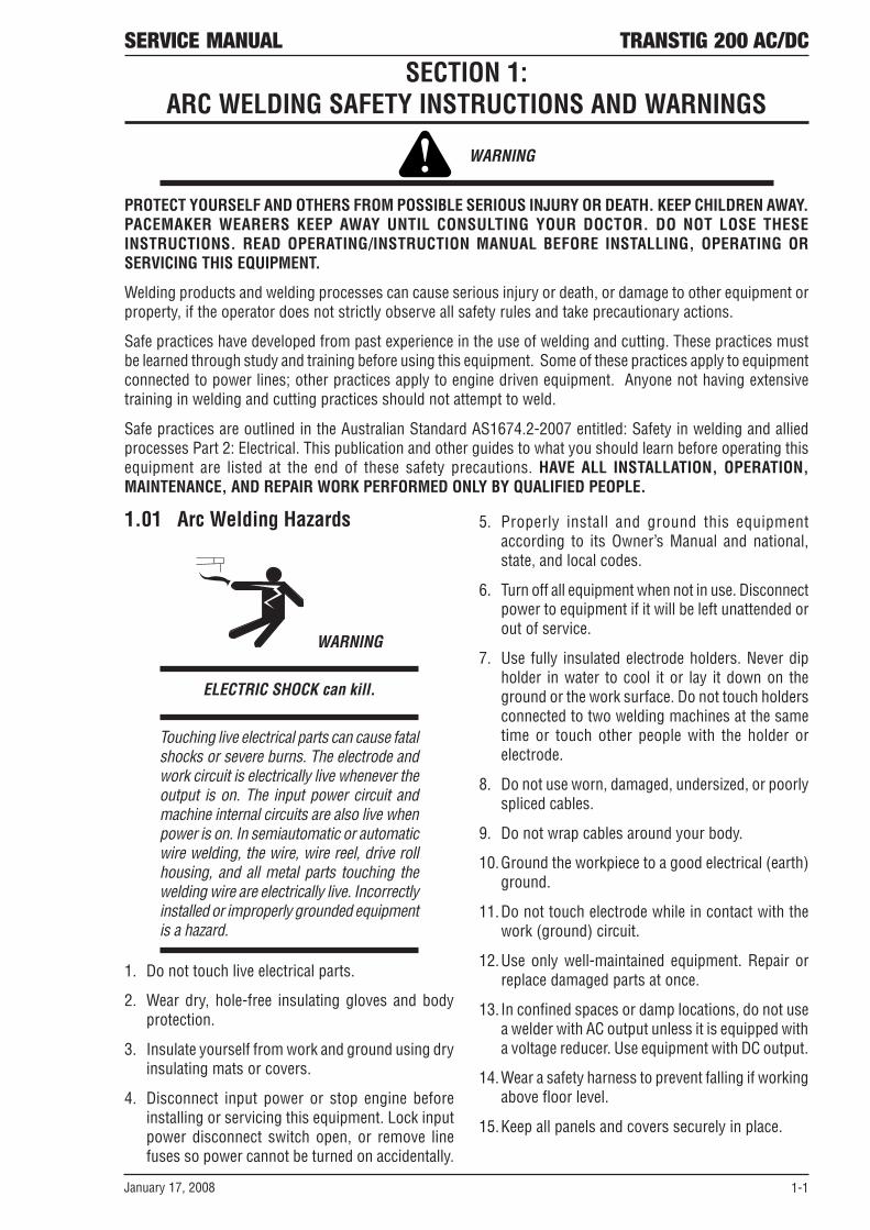
January 17, 2008 1-1
1.01 Arc Welding Hazards
WARNING
ELECTRIC SHOCK can kill.
Touching live electrical parts can cause fatalshocks or severe burns. The electrode andwork circuit is electrically live whenever theoutput is on. The input power circuit andmachine internal circuits are also live whenpower is on. In semiautomatic or automaticwire welding, the wire, wire reel, drive rollhousing, and all metal parts touching thewelding wire are electrically live. Incorrectlyinstalled or improperly grounded equipmentis a hazard.
1. Do not touch live electrical parts.
2. Wear dry, hole-free insulating gloves and bodyprotection.
3. Insulate yourself from work and ground using dryinsulating mats or covers.
4. Disconnect input power or stop engine beforeinstalling or servicing this equipment. Lock inputpower disconnect switch open, or remove linefuses so power cannot be turned on accidentally.
5. Properly install and ground this equipmentaccording to its Owner’s Manual and national,state, and local codes.
6. Turn off all equipment when not in use. Disconnectpower to equipment if it will be left unattended orout of service.
7. Use fully insulated electrode holders. Never dipholder in water to cool it or lay it down on theground or the work surface. Do not touch holdersconnected to two welding machines at the sametime or touch other people with the holder orelectrode.
8. Do not use worn, damaged, undersized, or poorlyspliced cables.
9. Do not wrap cables around your body.
10.Ground the workpiece to a good electrical (earth)ground.
11.Do not touch electrode while in contact with thework (ground) circuit.
12.Use only well-maintained equipment. Repair orreplace damaged parts at once.
13. In confined spaces or damp locations, do not usea welder with AC output unless it is equipped witha voltage reducer. Use equipment with DC output.
14.Wear a safety harness to prevent falling if workingabove floor level.
15.Keep all panels and covers securely in place.
SECTION 1:ARC WELDING SAFETY INSTRUCTIONS AND WARNINGS
WARNING
PROTECT YOURSELF AND OTHERS FROM POSSIBLE SERIOUS INJURY OR DEATH. KEEP CHILDREN AWAY.PACEMAKER WEARERS KEEP AWAY UNTIL CONSULTING YOUR DOCTOR. DO NOT LOSE THESEINSTRUCTIONS. READ OPERATING/INSTRUCTION MANUAL BEFORE INSTALLING, OPERATING ORSERVICING THIS EQUIPMENT.
Welding products and welding processes can cause serious injury or death, or damage to other equipment orproperty, if the operator does not strictly observe all safety rules and take precautionary actions.
Safe practices have developed from past experience in the use of welding and cutting. These practices mustbe learned through study and training before using this equipment. Some of these practices apply to equipmentconnected to power lines; other practices apply to engine driven equipment. Anyone not having extensivetraining in welding and cutting practices should not attempt to weld.
Safe practices are outlined in the Australian Standard AS1674.2-2007 entitled: Safety in welding and alliedprocesses Part 2: Electrical. This publication and other guides to what you should learn before operating thisequipment are listed at the end of these safety precautions. HAVE ALL INSTALLATION, OPERATION,MAINTENANCE, AND REPAIR WORK PERFORMED ONLY BY QUALIFIED PEOPLE.

TRANSTIG 200 AC/DC SERVICE MANUAL
1-2 January 17, 2008
WARNING
ARC RAYS can burn eyes and skin; NOISEcan damage hearing.
Arc rays from the welding processproduce intense heat and strong ultravioletrays that can burn eyes and skin. Noisefrom some processes can damagehearing.
1. Wear a welding helmet fitted with a proper shadeof filter (see ANSI Z49.1 listed in Safety Standards)to protect your face and eyes when welding orwatching.
2. Wear approved safety glasses. Side shieldsrecommended.
3. Use protective screens or barriers to protect othersfrom flash and glare; warn others not to watchthe arc.
4. Wear protective clothing made from durable,flame-resistant material (wool and leather) andfoot protection.
5. Use approved ear plugs or ear muffs if noise levelis high.
WARNING
FUMES AND GASES can be hazardous toyour health.
Welding produces fumes and gases.Breathing these fumes and gases can behazardous to your health.
1. Keep your head out of the fumes. Do not breaththe fumes.
2. If inside, ventilate the area and/or use exhaust atthe arc to remove welding fumes and gases.
3. If ventilation is poor, use an approved air-suppliedrespirator.
4. Read the Material Safety Data Sheets (MSDSs)and the manufacturer’s instruction for metals,consumables, coatings, and cleaners.
5. Work in a confined space only if it is well ventilated,or while wearing an air-supplied respirator.Shielding gases used for welding can displace aircausing injury or death. Be sure the breathing airis safe.
6. Do not weld in locations near degreasing, cleaning,or spraying operations. The heat and rays of thearc can react with vapors to form highly toxic andirritating gases.
7. Do not weld on coated metals, such as galvanized,lead, or cadmium plated steel, unless the coatingis removed from the weld area, the area is wellventilated, and if necessary, while wearing an air-supplied respirator. The coatings and any metalscontaining these elements can give off toxic fumesif welded.
Welding or Cutting operation
Electrode size Metal Thickness or Welding Current
Filter shade
no.
Welding or Cutting operation Electrode size Metal Thickness or Welding
Current
Filter shade
no.Torch soldering All 2Torch brazing All 2 or 3 Non Ferrous base metal All 11
Ferrous base metal All 12
Light Under 1 in., 25 mm 3 or 4 Gas tungsten arc welding (TIG) All 12
Medium 1 – 6 in., 25 – 150 mm 4 or 5 Atomic Hydrogen welding All 12
Heavy Over 6 in., 150 mm 5 or 6 Carbon Arc welding All 12
Plasma arc Welding All 12
Light Under 1/8 in., 3 mm 4 or 5 Carbon Arc GougingMedium 1/8 – 1/2 in., 3 – 12 mm 5 or 6 Light 12Heavy Over 1/2 in., 12 mm 6 or 8 Heavy 14
Under 5/32 in., 4 mm 10 Light Under 300 Amp 9Under 5/32 to ¼ in., 4 to 6.4mm 12 Medium 300 to 400 Amp 12Over ¼ in., 6.4 mm 14 Heavy Over 400 Amp 14
Eye protection filter shade selector for welding or cutting (goggles or helmet), from AWS A 8.2-73
Plasma arc cutting
Oxygen cutting
Gas metal arc welding
Gas welding
Shielded metal-arc welding (stick) electrodes

SERVICE MANUAL TRANSTIG 200 AC/DC
January 17, 2008 1-3
WARNING
WELDING can cause fire or explosion.
Sparks and spatter fly off from the weldingarc. The flying sparks and hot metal, weldspatter, hot workpiece, and hot equipmentcan cause fires and burns. Accidentalcontact of electrode or welding wire tometal objects can cause sparks,overheating, or fire.
1. Protect yourself and others from flying sparks andhot metal.
2. Do not weld where flying sparks can strikeflammable material.
3. Remove all flammables within 35 ft (10.7 m) ofthe welding arc. If this is not possible, tightly coverthem with approved covers.
4. Be alert that welding sparks and hot materials fromwelding can easily go through small cracks andopenings to adjacent areas.
5. Watch for fire, and keep a fire extinguisher nearby.
6. Be aware that welding on a ceiling, floor, bulkhead,or partition can cause fire on the hidden side.
7. Do not weld on closed containers such as tanksor drums.
8. Connect work cable to the work as close to thewelding area as practical to prevent weldingcurrent from traveling long, possibly unknownpaths and causing electric shock and fire hazards.
9. Do not use welder to thaw frozen pipes.
10.Remove stick electrode from holder or cut offwelding wire at contact tip when not in use.
WARNING
FLYING SPARKS AND HOT METAL cancause injury.
Chipping and grinding cause flying metal.As welds cool, they can throw off slag.
1. Wear approved face shield or safety goggles. Sideshields recommended.
2. Wear proper body protection to protect skin.
WARNING
CYLINDERS can explode if damaged.
Shielding gas cylinders contain gas underhigh pressure. If damaged, a cylinder canexplode. Since gas cylinders are normallypart of the welding process, be sure totreat them carefully.
1. Protect compressed gas cylinders from excessiveheat, mechanical shocks, and arcs.
2. Install and secure cylinders in an upright positionby chaining them to a stationary support orequipment cylinder rack to prevent falling ortipping.
3. Keep cylinders away from any welding or otherelectrical circuits.
4. Never allow a welding electrode to touch anycylinder.
5. Use only correct shielding gas cylinders,regulators, hoses, and fittings designed for thespecific application; maintain them and associatedparts in good condition.
6. Turn face away from valve outlet when openingcylinder valve.
7. Keep protective cap in place over valve exceptwhen cylinder is in use or connected for use.
8. Read and follow instructions on compressed gascylinders, associated equipment, and CGApublication P-1 listed in Safety Standards.

TRANSTIG 200 AC/DC SERVICE MANUAL
1-4 January 17, 2008
WARNING
Engines can be dangerous.
WARNING
ENGINE EXHAUST GASES can kill.
Engines produce harmful exhaust gases.
1. Use equipment outside in open, well-ventilatedareas.
2. If used in a closed area, vent engine exhaustoutside and away from any building air intakes.
WARNING
ENGINE FUEL can cause fire or explosion.
Engine fuel is highly flammable.
1. Stop engine before checking or adding fuel.
2. Do not add fuel while smoking or if unit is nearany sparks or open flames.
3. Allow engine to cool before fueling. If possible,check and add fuel to cold engine before beginningjob.
4. Do not overfill tank — allow room for fuel toexpand.
5. Do not spill fuel. If fuel is spilled, clean up beforestarting engine.
WARNING
MOVING PARTS can cause injury.
Moving parts, such as fans, rotors, and belts can cutfingers and hands and catch loose clothing.
1. Keep all doors, panels, covers, and guardsclosed and securely in place.
2. Stop engine before installing or connectingunit.
3. Have only qualified people remove guards orcovers for maintenance and troubleshootingas necessary.
4. To prevent accidental starting duringservicing, disconnect negative (-) batterycable from battery.
5. Keep hands, hair, loose clothing, and toolsaway from moving parts.
6. Reinstall panels or guards and close doorswhen servicing is finished and before startingengine.
WARNING
SPARKS can cause BATTERY GASES TOEXPLODE; BATTERY ACID can burn eyesand skin.
Batteries contain acid and generate explosive gases.
1. Always wear a face shield when working on abattery.
2. Stop engine before disconnecting or connectingbattery cables.
3. Do not allow tools to cause sparks when workingon a battery.
4. Do not use welder to charge batteries or jump startvehicles.
5. Observe correct polarity (+ and –) on batteries.

SERVICE MANUAL TRANSTIG 200 AC/DC
January 17, 2008 1-5
WARNING
STEAM AND PRESSURIZED HOTCOOLANT can burn face, eyes, and skin.
The coolant in the radiator can be very hotand under pressure.
1. Do not remove radiator cap when engine is hot.Allow engine to cool.
2. Wear gloves and put a rag over cap area whenremoving cap.
3. Allow pressure to escape before completelyremoving cap.
WARNING
This product, when used for welding orcutting, produces fumes or gases whichcontain chemicals know to the State ofCalifornia to cause birth defects and, insome cases, cancer. (California Health &Safety code Sec. 25249.5 et seq.)
NOTE
Considerations About Welding And TheEffects of Low Frequency Electric andMagnetic Fields
The following is a quotation from the GeneralConclusions Section of the U.S. Congress, Office ofTechnology Assessment, Biological Effects of PowerFrequency Electric & Magnetic Fields - BackgroundPaper, OTA-BP-E-63 (Washington, DC: U.S.Government Printing Office, May 1989): “...there isnow a very large volume of scientific findings basedon experiments at the cellular level and from studieswith animals and people which clearly establish thatlow frequency magnetic fields and interact with, andproduce changes in, biological systems. While mostof this work is of very high quality, the results arecomplex. Current scientific understanding does notyet allow us to interpret the evidence in a singlecoherent framework. Even more frustrating, it doesnot yet allow us to draw definite conclusions aboutquestions of possible risk or to offer clear science-based advice on strategies to minimize or avoidpotential risks.”
To reduce magnetic fields in the workplace, use thefollowing procedures.
1. Keep cables close together by twisting ortaping them.
2. Arrange cables to one side and away from theoperator.
3. Do not coil or drape cable around the body.
4. Keep welding power source and cables as faraway from body as practical.
ABOUT PACEMAKERS:
The above procedures are among thosealso normally recommended forpacemaker wearers. Consult your doctorfor complete information.
1.02 PRINCIPAL SAFETY STANDARDS
Safety in Welding and Cutting, ANSI Standard Z49.1,from American Welding Society, 550 N.W. LeJeuneRd., Miami, FL 33126.
Safety and Health Standards, OSHA 29 CFR 1910,from Superintendent of Documents, U.S. GovernmentPrinting Office, Washington, D.C. 20402.
Recommended Safe Practices for the Preparation forWelding and Cutting of Containers That Have HeldHazardous Substances, American Welding SocietyStandard AWS F4.1, from American Welding Society,550 N.W. LeJeune Rd., Miami, FL 33126.
National Electrical Code, NFPA Standard 70, fromNational Fire Protection Association, BatterymarchPark, Quincy, MA 02269.
Safe Handling of Compressed Gases in Cylinders, CGAPamphlet P-1, from Compressed Gas Association,1235 Jefferson Davis Highway, Suite 501, Arlington,VA 22202.
Code for Safety in Welding and Cutting, CSA StandardW117.2, from Canadian Standards Association,Standards Sales, 178 Rexdale Boulevard, Rexdale,Ontario, Canada M9W 1R3.
Safe Practices for Occupation and Educational Eyeand Face Protection, ANSI Standard Z87.1, fromAmerican National Standards Institute, 1430Broadway, New York, NY 10018.
Cutting and Welding Processes, NFPA Standard 51B,from National Fire Protection Association,Batterymarch Park, Quincy, MA 02269.
Safety in welding and allied processes Part 2:Electrical, AS1674.2-2007 from SAI Global Limited,www.saiglobal.com

TRANSTIG 200 AC/DC SERVICE MANUAL
1-6 January 17, 2008
1.03 DECLARATION OF CONFORMITY
Manufacturer: CIGWELDAddress: 71 Gower St, Preston
Victoria 3072
Australia
Description of equipment: Welding Equipment (GMAW, MMAW, GTAW). Including, but not limited to CIGWELDTranstig 200 Pi, Transtig 200 AC/DC, Transarc 300 Si, Transtig 300 Pi, Transtig 300 AC/DC, Transmig 400 i andassociated accessories.
Serial numbers are unique with each individual piece of equipment and details description, partsused to manufacture a unit and date of manufacture.
The equipment conforms to all applicable aspects and regulations of the ‘Low Voltage Directive’ (Directive73/23/EU, as recently changed in Directive 93/68/EU and to the National legislation for the enforcement of theDirective.
National Standard and Technical Specifications
The product is designed and manufactured to a number of standards and technical requirements among themare:
• AS/NZS 3652-(EMC Directive EN50199) applicable to arc welding equipment - generic emissions and
regulations.
• EN60974-1 applicable to welding equipment and associated accessories.
• AS60974.1 applicable to welding equipment and associated accessories.Extensive product design verification is conducted at the manufacturing facility as part of the routine designand manufacturing process, to ensure the product is safe and performs as specified. Rigorous testing isincorporated into the manufacturing process to ensure the manufactured product meets or exceeds all designspecifications.
CIGWELD has been manufacturing and merchandising an extensive equipment range with superior performance,ultra safe operation and world class quality for more than 30 years and will continue to achieve excellence.

SERVICE MANUAL TRANSTIG 200 AC/DC
January 17, 2008 2-1
SECTION 2:INTRODUCTION
2.01 How To Use This Manual
This Service Manual applies to just specification orpart numbers listed on page i.
To ensure safe operation, read the entire manual,including the chapter on safety instructions andwarnings.
Throughout this manual, the words WARNING,CAUTION, and NOTE may appear. Pay particularattention to the information provided under theseheadings. These special annotations are easilyrecognized as follows:
! WARNING
A WARNING gives information regardingpossible personal injury.
CAUTION
A CAUTION refers to possible equipmentdamage.
NOTE
A NOTE offers helpful informationconcerning certain operating procedures.
Additional copies of this manual may be purchasedby contacting CIGWELD at the address and phonenumber for your location listed in the inside back coverof this manual. Include the Transtig 200 AC/DCService Manual number and equipment identificationnumbers.
Electronic copies of this manual can also bedownloaded at no charge in Acrobat PDF format bygoing to the CIGWELD web site listed below andclicking on the Literature Library link:
http://www.cigweld.au.com
2.02 Equipment Identification
The unit’s identification number (specification or partnumber), model, and serial number usually appearon a nameplate attached to the control panel. In somecases, the nameplate may be attached to the rearpanel. Equipment which does not have a control panelsuch as gun and cable assemblies is identified onlyby the specification or part number printed on theshipping container. Record these numbers on thebottom of page i for future reference.
2.03 Receipt Of Equipment
When you receive the equipment, check it againstthe invoice to make sure it is complete and inspectthe equipment for possible damage due to shipping.If there is any damage, notify the carrier immediatelyto file a claim. Furnish complete informationconcerning damage claims or shipping errors to thelocation in your area listed in the inside back cover ofthis manual.
Include all equipment identification numbers asdescribed above along with a full description of theparts in error.
Move the equipment to the installation site before un-crating the unit. Use care to avoid damaging theequipment when using bars, hammers, etc., to un-crate the unit.
CAUTION
The products applicable to this ServiceManual are manufactured in variousconfigurations for differing globalrequirements. Some specifications andand electrical data quoted within thisService Manual may not be applicable toall products and regions. For this reasondue caution and care must be exercisedwhen using this Service Manual.

TRANSTIG 200 AC/DC SERVICE MANUAL
2-2 January 17, 2008
2.04 Symbol Chart
Note that only some of these symbols will appear on your model.
Gas Tungsten Arc Welding (GTAW)
Air Carbon Arc Cutting (CAC-A)
Constant Current
Constant Voltage Or Constant Potential
High Temperature
Fault Indication
Arc Force
Touch Start (GTAW)
Variable Inductance
Voltage Input
Single Phase
Three Phase
Three Phase Static Frequency Converter-Transformer-Rectifier
Dangerous Voltage
Off
On
Panel/Local
Shielded Metal Arc Welding (SMAW)
Gas Metal Arc Welding (GMAW)
Increase/Decrease
Circuit Breaker
AC Auxiliary Power
Remote
Duty Cycle
Percentage
Amperage
Voltage
Hertz (cycles/sec)
Frequency
Negative
Positive
Direct Current (DC)
Protective Earth (Ground)
Line
Line Connection
Auxiliary Power
Receptacle Rating-Auxiliary Power
Art # A-04130
115V 15A
t
t1
t2
%X
IPM
MPM
t
V
Fuse
Wire Feed Function
Wire Feed Towards Workpiece With Output Voltage Off.
Preflow Time
Postflow Time
Spot Time
Spot Weld Mode
Continuous WeldMode
Press to initiate wirefeed and welding, release to stop.
Purging Of Gas
Inches Per Minute
Meters Per Minute
Welding Gun
Burnback Time
Press and hold for preflow, releaseto start arc. Press to stop arc, andhold for preflow.
4 Step TriggerOperation
2 Step TriggerOperation
SERVICE MANUAL TRANSTIG 200 AC/DC
January 17, 2008 2-3
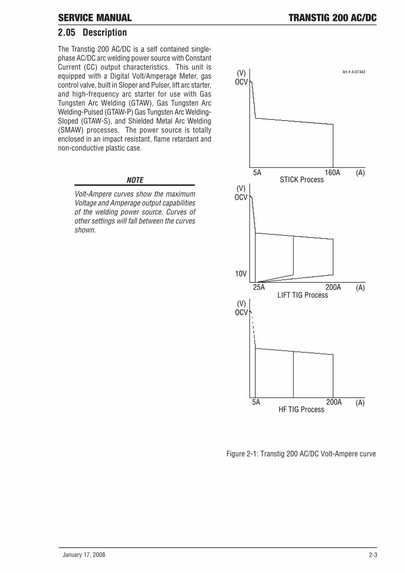
2.05 Description
The Transtig 200 AC/DC is a self contained single-phase AC/DC arc welding power source with ConstantCurrent (CC) output characteristics. This unit isequipped with a Digital Volt/Amperage Meter, gascontrol valve, built in Sloper and Pulser, lift arc starter,and high-frequency arc starter for use with GasTungsten Arc Welding (GTAW), Gas Tungsten ArcWelding-Pulsed (GTAW-P) Gas Tungsten Arc Welding-Sloped (GTAW-S), and Shielded Metal Arc Welding(SMAW) processes. The power source is totallyenclosed in an impact resistant, flame retardant andnon-conductive plastic case.
(V)OCV
5A 160A (A)STICK Process
(V)OCV
10V
25A 200A (A)LIFT TIG Process
(V)OCV
5A 200A (A)HF TIG Process
Art # A-07443
Figure 2-1: Transtig 200 AC/DC Volt-Ampere curve
NOTE
Volt-Ampere curves show the maximumVoltage and Amperage output capabilitiesof the welding power source. Curves ofother settings will fall between the curvesshown.

TRANSTIG 200 AC/DC SERVICE MANUAL
2-4 January 17, 2008
2.06 Functional Block Diagrams
Figure 2-2 illustrates the functional block diagram of the 200 AC/DC-power supply.
MainCircuitSwitchFilter
InputDiode
Primary
Capacitor
DC Power
VoltageSensor
IGBTInverter
ThermalDetector
To each control c ircuit+/-15VDC +18VDC+24VDC +5VDC
TroubleSensingCircuit
DriveCircuit
Torch ControlConnection
(CON1)
circuit
CurrentAdjustment
ReferenceAdjustment &
Mode select Switches
Panel Circuit Board
SequenceControl
ThemalSensorCircuit
MainTransformer
(PCB14)
OutputDiodes
HF-UNITControlCircuit
Stick ModeVRD
SensingCircuit
Lift T ig ModeOutput Short
SensingCircuit
Coupling
High
Coil
FrequencyUnit
Fan ControlCircuit
Gas ControlCircuit
Fan
Solenoid
Hall Current
Transformer(HCT1)
OutputInductor
ThermalDetector
+
-
+ -
Input
Power
Secondary
DC Power
Voltage SensorTo each control circuit
+/-12VDC +15VDC
SecondaryIGBT
Inverter
DriveCircuit
PrimaryCurrentSensor
Art # A-07267
Figure 2-2: Transtig 200 AC/DC Functional Block Diagram
2.07 Transporting Methods
This unit is equipped with a handle for carryingpurposes.
! WARNING
ELECTRIC SHOCK can kill. DO NOT TOUCHlive electrical parts. Disconnect inputpower conductors from de-energizedsupply line before moving the weldingpower source.
! WARNING
FALLING EQUIPMENT can cause seriouspersonal injury and equipment damage.
• Lift unit with handle on top of case.
• Use handcart or similar device of adequatecapacity.
• If using a fork lift vehicle, place and secure uniton a proper skid before transporting.

SERVICE MANUAL TRANSTIG 200 AC/DC
January 17, 2008 2-5
2.08 Parameter Specifications
Table 2-1: Parameter Specifications
Parameter Transtig 200 AC/DCPower Source Part Number 700719Cooling Fan CooledWelder Type Inverter Power SourceWelding Power Source Mass 19kgDimensions H 360mm x W 180mm x L 420mmManufactured to Australian Standard AS 60974.1-2006Number of Phases 1Nominal Supply Voltage 240V ±15%Nominal Supply Frequency 50HzProtection Class IP23S
Standard Specifications (Applicable with factory fitted Supply Plug)Parameter Transtig 200 AC/DC
Welding Current Range 5 - 200 AmpsOpen Circuit Voltage 65VFactory Fitted Supply Plug Rating 15 AmpsEffective Input Current (I1eff) 15 AmpsMaximum Input Current (I1 max) 36.7 AmpsSingle Phase Generator Requirement 8.8 KVAWelding Output (Quoted figures refer to MMAW output)
160A @ 15%, 26.4V80A @ 60%, 23.2V
62A @ 100%, 22.5VWelding Output (Quoted figures refer to GTAW output)
200A @ 20%, 18.0V130A @ 60%, 15.2V
100A @ 100%, 14.0V
Upgraded Specifications (Applicable with upgraded Supply Plug)Parameter Transtig 200 AC/DC
Welding Current Range 5 - 200 AmpsOpen Circuit Voltage 65VUpgraded Supply Plug Rating Required 25 AmpsEffective Input Current (I1eff) 23.2 AmpsMaximum Input Current (I1 max) 36.7 AmpsSingle Phase Generator Requirement 8.8 KVAWelding Output (Quoted figures refer to MMAW output)
160A @ 40%, 26.4V130A @ 60%, 25.2V
100A @ 100%, 24.0VWelding Output (Quoted figures refer to GTAW output)
200A @ 20%, 18.0V130A @ 60%, 15.2V
100A @ 100%, 14.0V

TRANSTIG 200 AC/DC SERVICE MANUAL
2-6 January 17, 2008
NOTES

January 17, 2008 3-1
SERVICE MANUAL TRANSTIG 200 AC/DC
SECTION 3: INSTALLATION
3.03 Electrical Input Connections
! WARNING
ELECTRIC SHOCK can kill; SIGNIFICANTDC VOLTAGE is present after removal ofinput power.
DO NOT TOUCH live electrical parts.
SHUT DOWN welding power source, disconnect inputpower employing lockout/tagging procedures.Lockout/tagging procedures consist of padlocking linedisconnect switch in open position, removing fusesfrom fuse box, or shutting off and red-tagging circuitbreaker or other disconnecting device.
3.01 Environment
The Transtig 200 AC/DC is designed for use inhazardous environments. Examples of environmentswith increased hazardous conditions are:
a. In locations in which freedom of movement isrestricted, so that the operator is forced to performthe work in a cramped (kneeling, sitting or lying)position with physical contact with conductiveparts;
b. In locations which are fully or partially limited byconductive elements, and in which there is a highrisk of unavoidable or accidental contact by theoperator, or
c. In wet or damp hot locations where humidity orperspiration considerably reduces the skinresistance of the human body and the insulationproperties of accessories.
Environments with hazardous conditions do notinclude places where electrically conductive parts inthe near vicinity of the operator, which can causeincreased hazard, have been insulated.
3.02 Location
Be sure to locate the welder according to the followingguidelines:
· In areas, free from moisture and dust.
· Ambient temperature between 0 degrees C to40 degrees C.
· In areas, free from oil, steam and corrosivegases.
· In areas, not subjected to abnormal vibrationor shock.
· In areas, not exposed to direct sunlight or rain.
· Place at a distance of 12” (304.79mm) or morefrom walls or similar that could restrict naturalairflow for cooling.
! WARNING
CIGWELD advises that this equipment beelectrically connected by a qualifiedelectrician.
3-2 January 17, 2008
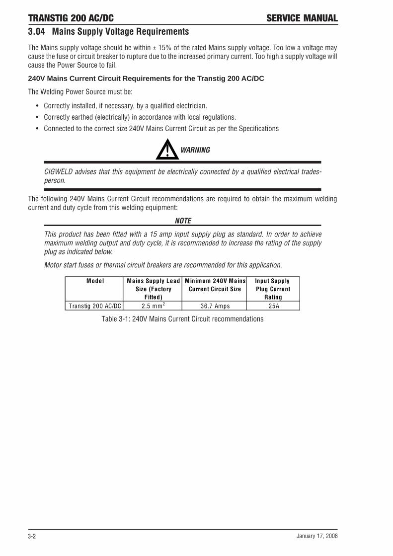
TRANSTIG 200 AC/DC SERVICE MANUAL3.04 Mains Supply Voltage Requirements
The Mains supply voltage should be within ± 15% of the rated Mains supply voltage. Too low a voltage maycause the fuse or circuit breaker to rupture due to the increased primary current. Too high a supply voltage willcause the Power Source to fail.
240V Mains Current Circuit Requirements for the Transtig 200 AC/DC
The Welding Power Source must be:
• Correctly installed, if necessary, by a qualified electrician.
• Correctly earthed (electrically) in accordance with local regulations.
• Connected to the correct size 240V Mains Current Circuit as per the Specifications
! WARNING
CIGWELD advises that this equipment be electrically connected by a qualified electrical trades-person.
The following 240V Mains Current Circuit recommendations are required to obtain the maximum weldingcurrent and duty cycle from this welding equipment:
NOTE
This product has been fitted with a 15 amp input supply plug as standard. In order to achievemaximum welding output and duty cycle, it is recommended to increase the rating of the supplyplug as indicated below.
Motor start fuses or thermal circuit breakers are recommended for this application.
Model Mains Supply Lead Minimum 240V Mains Input Supply Size (Factory Current Circuit Size Plug Current Fitted) Rating
Transtig 200 AC/DC 2.5 mm2 36.7 Amps 25A
Table 3-1: 240V Mains Current Circuit recommendations

January 17, 2008 3-3
SERVICE MANUAL TRANSTIG 200 AC/DC3.05 High Frequency Introduction
The importance of correct installation of highfrequency welding equipment cannot beoveremphasized. Interference due to high frequencyinitiated or stabilized arc is almost invariably tracedto improper installation. The following information isintended as a guide for personnel installing highfrequency welding machines.
! WARNING: EXPLOSIVES
The high frequency section of this machinehas an output similar to a radio transmitter.The machine should NOT be used in thevicinity of blasting operations due to thedanger of premature firing.
! WARNING: COMPUTERS
It is also possible that operation close tocomputer installations may causecomputer malfunction.
3.06 High Frequency Interference
Interference may be transmitted by a high frequencyinitiated or stabilized arc welding machine in thefollowing ways:
1. Direct Radiation: Radiation from the machine canoccur if the case is metal and is not properlygrounded. It can occur through apertures suchas open access panels. The shielding of the highfrequency unit in the Power Source will preventdirect radiation if the equipment is properlygrounded.
2. Transmission via the Supply Lead: Withoutadequate shielding and filtering, high frequencyenergy may be fed to the wiring within theinstallation (mains) by direct coupling. The energyis then transmitted by both radiation andconduction. Adequate shielding and filtering isprovided in the Power Source.
3. Radiation from Welding Leads: Radiatedinterference from welding leads, althoughpronounced in the vicinity of the leads, diminishesrapidly with distance. Keeping leads as short aspossible will minimize this type of interference.Looping and suspending of leads should beavoided where possible.
4. Re-radiation from Unearthed Metallic Objects:A major factor contributing to interference is re-radiation from unearthed metallic objects closeto the welding leads. Effective grounding of suchobjects will prevent re-radiation in most cases.

3-4 January 17, 2008
TRANSTIG 200 AC/DC SERVICE MANUAL3.07 Duty Cycle
The duty cycle of a welding power source is thepercentage of a ten (10) minute period that it can beoperated at a given output without causingoverheating and damage to the unit. If the weldingamperes decrease, the duty cycle increases. If thewelding amperes are increased beyond the ratedoutput, the duty cycle will decrease.
! WARNING
Exceeding the duty cycle ratings will causethe thermal overload protection circuit tobecome energized and shut down theoutput until the unit has cooled to normaloperating temperature.
CAUTION
Continually exceeding the duty cycleratings can cause damage to the weldingpower source and will void themanufacturer's warranty.
NOTE
Due to variations that can occur inmanufactured products, claimedperformance, voltages, ratings, allcapacities, measurements, dimensionsand weights quoted are approximate only.Achievable capacities and ratings in useand operation will depend upon correctinstallation, use, applications,maintenance and service.

January 17, 2008 4-1
SERVICE MANUAL TRANSTIG 200 AC/DC
SECTION 4:OPERATOR CONTROLS
4.01 Transtig 200 AC/DC Controls
1
3
2
5
48
6
7
Art # A-08341_AC
Figure 4-1: Transtig 200 AC/DC Power Source
1. Control Knob: This control sets the selected weldparameter, rotating it clockwise increases theparameter that is indicated on the digital meter.Pushing the knob inward displays the actual weldingvoltage.
2 . Remote Control Socket: The 8 pin RemoteControl Socket is used to connect remote currentcontrol devices to the welding Power Source. Tomake connections, align keyway, insert plug, androtate threaded collar fully clockwise.
Art # A-04984
2 1
5 4 3
678
1 2 3 4 5 6 7 8
5k Ohms
GND
Figure 4-2: 8-Socket Receptacle
Socket Pin Function1 Earth (Ground)
Torch Switch Input (24V) to (connect pins 2 & 3 to turn on welding current)
3 Torch Switch Input (0V) to energize weld current (connect pins 2 & 3 to turn on welding current)
4 Not Used5 5k ohm (maximum) connection
to 5k ohm remote controlpotentiometer
6 Zero ohm (minimum) connection to 5k ohm remote control potentiometer
7 Wiper arm connection to 5k ohmremote control potentiometer
8 Not Used
2
Table 4-1: Socket Pin Functions

4-2 January 17, 2008
TRANSTIG 200 AC/DC SERVICE MANUAL3. Positive Terminal: Welding current flows from
the Power Source via heavy duty Dinse typeterminal. It is essential, however, that the maleplug is inserted and turned securely to achieve asound electrical connection.
4. Negative Terminal: Welding current flows fromthe Power Source via heavy duty Dinse typeterminal. It is essential, however, that the maleplug is inserted and turned securely to achieve asound electrical connection.
CAUTION
Loose welding terminal connections cancause overheating and result in the maleplug being fused in the bayonet terminal.
5. Gas Outlet: Torch / Gas Terminal is an all-in-onedesign of the Gas Outlet and the Negative Terminal.Gas Outlet is a 5/8-18 UNF female gas fitting.
6. ON/OFF Switch: This switch connects the Primarysupply voltage to the inverter when in the ONposition. This enables the Power Supply.
! WARNING
When the welder is connected to thePrimary supply voltage, the internalelectrical components may be at 240Vpotential with respect to earth.
7. Input Cable: The input cable connects the Primarysupply voltage to the equipment.
8 . Gas Inlet: The Gas Inlet is a 5/8-18 UNF female gasfitting.

January 17, 2008 4-3
SERVICE MANUAL TRANSTIG 200 AC/DC4.02 Weld Process Selection for Transtig 200 AC/DC
Weld Mode
Weld Process Selection
STICK
HF TIG
LIFT TIG
Description
STD
Yes Yes Yes 2T operation in TIG Modes using remote devices to control contactor & current
SLOPE
No Yes Yes 4T operation in TIG Modes with crater fill using a remote contactor device to control sequence.
REPEAT
No Yes Yes 4T operation in TIG Modes with repeat operation and crater fill using a remote contactor device.
SPOT
No Yes No 2T operation spot welding in HF TIG using a remote contactor device.
PULSE ON/OFF
No Yes Yes Pulse operation in TIG Modes
Yes Yes Yes Selects AC or DC weld current
Operation
PANEL/REMOTE
Yes Yes Yes Selects mode of operation: Panel or Remote
Table 4-2: Weld Process selection versus Weld Mode for Transtig 200 AC/DC

4-4 January 17, 2008
TRANSTIG 200 AC/DC SERVICE MANUAL4.03 Weld Parameter Descriptions for Transtig 200 AC/DC
Art # A-07237_AC
PRESS AND HOLD
Figure 4-3: Transtig 200 AC/DC Front Panel
Parameter Description
This parameter operates in all weld modes except Lift TIG mode and is used to heat up the weld zone in TIG modes or improve the start characteristics for stick electrodes. e.g. low hydrogen electrodes. It sets the peak start current on top of the BASE (WELD) current.e.g. HOT START current = 130 amps when BASE (WELD) = 100 amps & HOT START = 30 amps
INITIAL CUR. This parameter operates in SLOPE or REPEAT (4T) TIG modes only and is used to set the start current for TIG. The Start Current remains on until the torch trigger switch is released after it has been depressed.
UP SLOPE This parameter operates in TIG modes only and is used to set the time for the weld current to ramp up, after the torch trigger switch has been pressed then released, from INITIAL CUR to PEAK or BASE current
This parameter operates in TIG modes only and is used to provide gas to the weld zone prior to striking the arc, once the torch trigger switch has been pressed. This control is used to dramatically reduce weld porosity at the start of a weld.
HOT START
PRE-FLOW
Table 4-3: Transtig 200 AC/DC Front Panel Parameter Description

January 17, 2008 4-5
SERVICE MANUAL TRANSTIG 200 AC/DC
PEAK CUR. This parameter sets the PEAK weld current when in PULSE modeWELD This parameter sets the TIG WELD current in STD , SLOPE , REPEAT and
SPOT modes when PULSE is OFF. This parameter also sets the STICK weld current.
BASE (BackgroundCurrent)
This parameter sets the Background current when in Pulse TIG mode.
SPOT TIME This parameter sets the duration of the SPOT TIME in HF TIG mode onlyPULSE WIDTH This parameter sets the percentage on time of the PULSE FREQUENCY
for PEAK weld current when the PULSE is ON.PULSE FREQ. This parameter sets the PULSE FREQUENCY when the PULSE is ON.
AC FREQUENCY This parameter operates in AC mode only and is used to set the frequency for the AC weld current.
DOWN SLOPE This parameter operates in TIG modes only and is used to set the time for the weld current to ramp down, after the torch trigger switch has been pressed, to CRATER CUR. This control is used to eliminate the crater that can form at the completion of a weld.
CRATER CUR. This parameter operates in SLOPE or REPEAT (4T) TIG modes only and is used to set the finish current for TIG. The CRATER Current remains ON until the torch trigger switch is released after it has been depressed.
The SAVE/LOAD buttons are used to save and retrieve a total number of 5 programs into the 200AC/DC memory. Note: Press button for three seconds to store settings.
WAVE BALANCE This parameter is used for aluminum AC TIG mode and is used to set the penetration to cleaning action ratio for the AC weld current. GenerallyWAVE BALANCE is set to 50% for AC STICK welding. The WAVE BALANCE control changes the ratio of penetration to cleaning action ofthe AC TIG welding arc. Maximum weld penetration is achieved whenthe WAVE BALANCE control is set to 10%. Maximum cleaning of heavilyoxidised aluminium or magnesium alloys is achieved when the WAVE BALANCE control is set to 65%.
POST-FLOW
This parameter operates in TIG modes only and is used to adjust the post gas flow time once the arc has extinguished. This control is used to dramatically reduce oxidation of the tungsten electrode.
WAVE BALANCE=10%
Maximum Penetration andreduced cleaning
WAVE BALANCE=50%
Balanced with 50% penetrationand 50% cle aning
WAVE BALANCE=65%
Maximum Cle aning andreduced penetration
10%50% 65%
90%50% 35%
(+ )(+ ) (+ )
(-)(-) (-)
Table 4-3: Transtig 200 AC/DC Front Panel Parameter Description (cont.)

4-6 January 17, 2008
TRANSTIG 200 AC/DC SERVICE MANUAL4.04 Weld Parameters for Transtig 200 AC/DC
Weld HFParameter STICK TIGPRE-FLOW 0.0 to 1.0 sec 0.1 sec 0.1 sec No Yes YesHOT START 0 to 70A 20A 1A Yes Yes No
INITIAL CUR. 5 to 185A 30A 1A No Yes YesUP SLOPE 0 to 15 sec 1 sec 0.1 sec No Yes YesPEAK CUR. 5 to 185A 120A 1A No Yes YesWELD CUR
(TIG)WELD CUR (STICK)
5 to 160A 80A 1A Yes No No
SPOT TIME 0.5 to 5.0 sec 2 sec 0.1 sec No Yes YesPULSE WIDTH 15 to 80% 50% 1% No Yes Yes
See Table 6
AC FREQUENCY 15 to 150Hz 50Hz 1Hz Yes Yes YesWAVE BALANCE 10 to 65% 50% 1% Yes Yes YesDOWN SLOPE 0 to 25 sec 3 sec 0.1 sec No Yes YesCRATER CUR. 5 to 185A 30A 1A No Yes YesPOST-FLOW 0.0 to 60 sec 10 sec 0.1 sec No Yes Yes
Weld ModeParameter
RangeFactory Setting
Incremental Unit
LIFT TIG
PULSE FREQ. 0.5 to 500Hz 100.0Hz No Yes Yes
5 to 185A 80A 1A No Yes Yes
Table 4-4: Weld Parameters for Transtig 200 AC/DC
PULSE FREQ. Range Incremental Unit 0.5 to 20Hz 0.1Hz 20 to 100Hz 1Hz
100 to 500Hz 5Hz
Table 4-5: PULSE FREQ. Range and Incremental Units

January 17, 2008 4-7
SERVICE MANUAL TRANSTIG 200 AC/DC4.05 Power Source Features
Feature Description New Digital Control • Almost all welding parameters are adjustable Touch Panel Switches • Touch switches eliminate mechanical damage Front Control Cover • Protects front panel controls Digital Meter • Displays selected weld parameter value
• Displays weld current when welding • Displays weld current for 20 seconds after weld has
been completed • A selected weld parameter value can be adjusted at
any time even while welding Intelligent Fan Control • The intelligent cooling system is designed to reduce
dust and foreign material build-up, whilst providing optimum cooling
• Fan speed reduces approximately 30 seconds after machine is turned on
• Fan speed increases when internal components reaches operating temperature
ON/OFF Switch • Primary voltage Supply ON/OFF switch located on rear panel
Voltage Reduction Device (VRD)
Reduces the OCV when the power supply is not in use. Eliminates the need for add on voltage reducers and has no effect on arc starting. • VRD fully complies to AS 60974.1 • When Stick mode is selected the green VRD light is
ON when not welding and red when welding • When in TIG modes VRD is OFF.
Control Knob • For the selected weld parameter, rotating the knob clockwise increases the parameter
• Rotating the knob counter-clockwise decreases the parameter
• A selected weld parameter value can be adjusted at any time even while welding
• Pushing the knob in displays actual arc voltage Self Diagnosis using Error Codes • An error code is displayed on the Digital Meter when a
problem occurs with Primary supply voltage or internal component problems. Refer to troubleshooting guide.
Table 4-6: Power Source Features

4-8 January 17, 2008
TRANSTIG 200 AC/DC SERVICE MANUAL
Feature Description
Save/Load Function • A total number of 5 programs can be saved into the 200 AC/DC memory.
SAVE the Current Weld Parameters into Memory • Press and HOLD the SAVE button for three seconds. Beep
will sound and the Digital Meter will show a number 1. • Select a memory location by rotating the control knob,
1 to 5 is displayed on the meter. • After selecting the desired memory location (i.e. 1 to 5),
press the right scroll button and the machine will give a beep to confirm the weld parameters from the control panel are saved.
LOAD (retrieve) a Program to Control Panel • Press and HOLD the LOAD button for three seconds. Beep
will sound and the Digital Meter display will show a number 1.
• Select a memory location by rotating the control knob, 1 to 5 is displayed on the meter.
After selecting the desired memory location (i.e. 1 to 5), press the right scroll button and the machine will give a beep to confirm the weld parameters are loaded onto the control panel.
Table 4-6:Power Source Features (cont.)

January 17, 2008 5-1
SERVICE MANUAL TRANSTIG 200 AC/DC
SECTION 5:SET-UP FOR SMAW (STICK) AND GTAW (TIG)
Conventional operating procedures apply when usingthe Welding Power Source, i.e. connect work leaddirectly to work piece and electrode lead is used tohold electrode. Wide safety margins provided by thecoil design ensure that the Welding Power Sourcewill withstand short-term overload without adverseeffects. The welding current range values should beused as a guide only. Current delivered to the arc isdependent on the welding arc voltage, and as weldingarc voltage varies between different classes ofelectrodes, welding current at any one setting wouldvary according to the type of electrode in use. Theoperator should use the welding current range valuesas a guide, then finally adjust the current setting tosuit the application.
! WARNING
Before connecting the work clamp to thework and inserting the electrode in theelectrode holder make sure the Primarypower supply is switched off.
CAUTION
Remove any packaging material prior touse. Do not block the air vents at the frontor rear or sides of the Welding PowerSource.
CAUTION
DO NOT change the Weld Mode or WeldProcess Mode until after POST-FLOW timehas finished.
Art # A-07843
Figure 5-1: Transtig 200 AC/DC Set-up

5-2 January 17, 2008
TRANSTIG 200 AC/DC SERVICE MANUAL
NOTES

January 17, 2008 6-1
SERVICE MANUAL TRANSTIG 200 AC/DC
SECTION 6: SEQUENCE OF OPERATION
Scroll Buttons are used to select the parameters to be set. The LED’s show which function isbeing adjusted on the weld sequence graph. Refer to the Symbols Table located in the frontof the manual for Symbol descriptions.
1
8
3
4 6
9
2
7
5
Art # A-07272_AC
PRESS AND HOLD
Figure 6-1: Transtig 200 AC/DC Front Panel
1. Pulse Function: Pressing this button enables the TIG current pulse functions.
2. Remote Current Function: Pressing this buttons enables remote current functions.
3. TIG Mode Functions: Pressing this button scrolls through the output TIG function modes (Standard,Slope, Slope w/repeat, Spot).
4. Digital LED Display: Welding amperage and parameter values are displayed in this window. Internalwarnings such as over temperature, low or high input voltage applied are signaled to the operator bya warning sound and error message on the screen.
5. Save/Load Buttons: By using the Save & Load buttons the operator can easily save up to five weldingparameter programs. The buttons must be pressed for three seconds to store the settings.
6. Control Knob: Allows the operator to adjust the output amperage within the entire range of the powersource and sets each parameter value.
7. Process Button: This button selects between STICK, HF TIG and Lift TIG mode.
8. Scroll Buttons: Used to select the parameters to be set. The LED’s show which function is beingadjusted on the Sequence Graph.
9. AC/DC Button: Selects between AC or DC welding output.
6-2 January 17, 2008
TRANSTIG 200 AC/DC SERVICE MANUAL
6.01 Stick Welding
· Connect work lead to negative terminal· Connect electrode lead to positive terminal· Switch machine on· Set AC or DC weld current. If AC is selected then
set AC FREQ to 60Hz & WAVE BALANCE to 50%.· Set Contractor· Connect remote control device if required
Use the Scroll Buttons to move to the parameter tobe set. The LED will show which function is beingadjusted on the weld sequence graph. Use the controlknob to adjust each parameter.
· Set HOT START
· Set WELD currentCommence welding
6.02 AC or DC HF TIG Welding
· Connect work lead to positive terminal
· Connect TIG torch to gas terminal
· Switch machine on
· Set AC or DC weld current. If AC is selected thenset AC FREQ & WAVE BALANCE
· Connect remote control device if required
Use the Scroll Buttons to move to the parameter tobe set. The LED will show which function is beingadjusted on the weld sequence graph. Use the controlknob to adjust each parameter.
· Set PRE-FLOW time
· Set HOT START current
· Set POST-FLOW time
· Set (WELD) PEAK CUR current
· Set POST-FLOW timeSlope Mode Parameters if required
· Set INITIAL CUR current
· Set UP SLOPE time
· Set (WELD) PEAK CUR current
· Set BASE current
· Set DOWN SLOPE time
· Set CRATER CUR currentPulse Mode parameters if required
· Set PULSE WIDTH % for PEAK CURRENT· Set PEAK CURRENT· Set PULSE FREQ
Commence welding

January 17, 2008 6-3
SERVICE MANUAL TRANSTIG 200 AC/DC
6.03 Slope Mode Sequence
Weld Current Down Slope
Up Slope Initial
Current
Switch Closed
Switch Open
Switch Closed
Switch Open
Preflow
Final Current
Postflow
Art # A-04989
Figure 6-2: Slope Mode Sequence
1. To start Slope sequence Close remote switchcontacts. Once the welding arc is established thePower Source will maintain initial current settingas long as the remote switch contacts are closed.
a. In the HF TIG mode, after Preflow time, HighFrequency is present at the torch. When thetorch is positioned close to the work thewelding current will transfer to the work andestablish the arc at the initial current setting.
b. In the Lift TIG mode, after Preflow time, LiftStart current is present at the torch. Whenthe electrode is touched to the work and liftedoff, the welding arc is established at the initialcurrent setting.
6.04 Slope Mode with Repeat Sequence
The repeat function is operated during the down slope cycle of the Slope Sequence and is active through thedown slope period only. During the down slope period, by opening the Remote Switch contacts, the currentwill increase back to weld current. Within the Down Slope period the repeat function can be operated as manytimes as desired. To continue slope cycle and end slope sequence close remote switch contacts and allowweld current to reach final current setting. Once final current setting is reached, opening the Remote Switchagain will turn off the welding arc and post flow begins.
2. Open Remote Switch – current increases to weldcurrent. Once welding arc has reached weldcurrent the power source will maintain weldcurrent as long as the remote switch contacts areopen.
3. Close Remote Switch – Welding current decreasesto final current setting. Once final welding currentis reached the power source will maintain finalcurrent setting as long as the remote switchcontacts are closed.
4. Open Remote Switch – Welding arc stops and postflow begins.
NOTE
Slope function operates with a RemoteON/OFF device only

6-4 January 17, 2008
TRANSTIG 200 AC/DC SERVICE MANUAL
6.05 Pulse Controls
(Peak Current) (Base)
Background Current
(Pulse Width) (Pulse Frequency) Art # A-04990
Figure 6-3: Pulse Controls
The Pulse controls are used primarily to control heat input. Pulse offers a number of advantages as follows:
1) Control puddle – size and fluidity (especially out of position).
2) Increase penetration
3) Travel speed control
4) Better consistent quality
5) Decreased distortion on lighter or thinner materials
Pulse-current provides a system in which the welding current continuously changes between two levels.During the periods of Peak current, heating and fusion takes place, and during the background (base) currentperiods, cooling and solidification take place. Pulse Width is the time in one cycle the current remains at thepeak current setting. Pulse Frequency, measured in Hertz, is the number of cycles per second the currenttravels between peak and background current settings. It is as if the foot rheostat were moved up and downto increase and decrease the welding current on a regular basis. The faster you moved the foot rheostat upand down the faster the frequency.

January 17, 2008 7-1
SERVICE MANUAL TRANSTIG 200 AC/DC
SECTION 7:BASIC TIG WELDING GUIDE
7.01 Explanation of “Fluttery Arc”when AC TIG Welding onAluminum
The following will assist in understanding thephenomenon of Arc Flutter, also referred to as ArcRectification.
The basic thesis is that the fluttering is caused bylack of oxide in the weld pool.
The oxide layer on the plate reduced the energy forelectron emission. Electron emission from the weldpool (DC+) causes the oxide layers to be disrupted,the so-called “cleaning action”. However once thecleaning action has produced a mirror like surface onthe weld pool, the effect of the oxide layer is limitedbecause the oxide layer has dissipated. This makeselectron emission from the weld pool more difficultand increases the chance of arc instability.
This idea is supported by the observation that oncefluttering starts it can be made to stop by workingthe arc away from the mirror like weld pool to an areaof oxide coated material. As soon as this is done thearc settles back to a stable condition. So while thearc is “consuming” oxide coated plate the instabilitydoes not occur. But once the arc is stationary, thepool becomes thoroughly “cleaned” by electionemission, the fluttering begins.
Tests conducted on various types of AC TIG powersources, Fluttery Arc is not confined to one type ofpower source or its' design, both conventional andinverter types suffer from the same problem.
AC TIG on aluminum
1. The Problem: Arc appears unstable and pulses or flutters. ie. appears to rapidly change welding current.
Conditions that accentuate arc flutter: Conditions that minimizes arc flutter:
• Cold work piece • Preheat the work piece
• Very short arc length • Increase the arc length
• Weld pool crater about 0.39” to 0.47” (10 to 12mm) diameter
• Introduce filler rod material to the weld pool, which introduces oxides
• Arc field in one spot to produce “mirror” clean weld pool
• Move the weld pool around to introduce oxides to the weld pool
• Increased cleaning action i.e. Prolonged oxide emission from a stationary weld pool increases the likelihood of arc flutter
• Decrease the cleaning action by turning the WAVE BALANCE to below 50% or move the weld pool around
• Accentuated when tungsten running near its current capacity, i.e. Molten ball on end
• Use a larger diameter tungsten electrode
Table 7-1: Reduction of Arc Flutter
2. Conclusion: Fluttery Arc in AC TIG is a physical phenomenon independent of machine design.

7-2 January 17, 2008
TRANSTIG 200 AC/DC SERVICE MANUAL7.02 Electrode Polarity
Connect the TIG torch to the - / TORCH terminal and the work lead to the + / WORK terminal for direct currentstraight polarity. Direct current straight polarity is the most widely used polarity for DC TIG welding. It allowslimited wear of the electrode since 70% of the heat is concentrated at the work piece.
7.03 Tungsten Electrode Current Ranges
Electrode Diameter AC Current (Amps) DC Current (Amps)0.040” (1.0mm) 30 – 70 30 – 601/16” (1.6mm) 60 – 95 60 – 1153/32” (2.4mm) 125 – 150 100 – 1651/8” (3.2mm) 130 – 225 135 – 200
5/32” (4.0mm) 190 – 280 190 – 2803/16” (4.8mm) 250 – 340 250 – 340
Table 7-2: Current ranges for various tungsten electrode sizes
7.04 Tungsten Electrode Types
Electrode Type (Ground Finish)
Welding Application Features Color Code
Thoriated 2%
DC welding of mild steel, stainless steel and copper
Excellent arc starting, long life, high current carrying capacity
Red
Zirconated 1%
High quality AC welding of aluminium, magnesium and their alloys
Self cleaning, long life, maintains balled end, high current carrying capacity
White
Ceriated 2%
AC & DC welding of mild steel, stainless steel, copper, aluminium, magnesium and their alloys
Longer life, more stable arc, easier starting, wider current range, narrower more concentrated arc
Grey
Table 7-3: Tungsten Electrode Types

January 17, 2008 7-3
SERVICE MANUAL TRANSTIG 200 AC/DC7.05 Guide for Selecting Filler Wire Diameter
NOTE
The filler wire diameter specified in Table 7-4 is a guide only, other diameter wires may be usedaccording to the welding application
AC Current Range DC Current Range(Amps) (Amps)
1/16” (1.6 mm) 30-95 20 - 903/32” (2.4 mm) 125-160 65 - 1151/8” (3.2 mm) 180-240 100 - 165
3/16” (4.8 mm) 220-320 200-350
Filler Wire Diameter
Table 7-4: Filler Wire Selection Guide
7.06 Shielding Gas Selection
Shielding Gas
Aluminium & alloys Welding ArgonCarbon Steel Welding ArgonStainless Steel Welding ArgonCopper Welding Argon
Alloy
Table 7-5: Shielding Gas Selection
7.07 TIG Welding Parameters for Low Carbon & Low Alloy Steel Pipe
Current Range DCAmperes
Thoriated 2%3/32” (2.4 mm)Thoriated 2%
3/32” (2.4 mm)Thoriated 2%
3/32” (2.4 mm)
Electrode Type & Diameter
Filler Rod for Root Pass
Joint Preparation
120 - 170 Yes
100 - 160 Yes
90 - 130 No
Table 7-6: TIG Welding Parameters for Low Carbon & Low Alloy Steel Pipe

7-4 January 17, 2008
TRANSTIG 200 AC/DC SERVICE MANUAL7.08 Welding Parameters for Aluminum
Filler Rod Diameter
(if required)0.040” 30-45 0.040” 1/16” Butt/Corner1.0mm 35-50 1.0mm 1.6mm Lap/ Fillet0.045” 40-60 0.040” 1/16” Butt/Corner1.2mm 45-70 1.0mm 1.6mm Lap/ Fillet1/16” 60-85 1/16” 1/16” Butt/Corner
1.6mm 70-95 1.6mm 1.6mm Lap/ Fillet1/8” 3/32” 3/32”
3.2mm 2.4mm 2.4mm1/8”
3.2mm3/16” 180-225 1/8” 1/8” Butt/Corner
4.8mm 190-240 3.2mm 3.2mm Lap/ Fillet¼” 240-280 3/16” 3/16” Butt/Corner
6.4mm 250-320 4.8mm 4.8mm Lap/ Fillet
125-150 130-160
Base Metal Thickness
AC Current for Aluminum
Tungsten Electrode Diameter
10
13
Joint Type
Butt/Corner Lap/Fillet
5-7
5-7
7
10
Argon Gas Flow Rate Liters/min
Table 7-7: AC TIG Welding Parameters
7.09 Welding Parameters for Steel
Filler Rod Diameter
(if required)0.040” 35-45 20-30 0.040” 1/16” Butt/Corner1.0mm 40-50 25-35 1.0mm 1.6mm Lap/ Fillet0.045” 45-55 30-45 0.040” 1/16” Butt/Corner1.2mm 50-60 35-50 1.0mm 1.6mm Lap/ Fillet1/16” 60-70 40-60 1/16” 1/16” Butt/Corner
1.6mm 70-90 50-70 1.6mm 1.6mm Lap/ Fillet1/8” 80-100 65-85 1/16” 3/32” Butt/Corner
3.2mm 90-115 90-110 1.6mm 2.4mm Lap/ Fillet3/16” 115-135 100-125 3/32” 1/8” Butt/Corner
4.8mm 140-165 125-150 2.4mm 3.2mm Lap/ Fillet¼” 160-175 135-160 1/8” 5/32” Butt/Corner
6.4mm 170-200 160-180 3.2mm 4.0mm Lap/ Fillet
Base Metal Thickness
DC Current for Mild
Steel
DC Current for Stainless
Steel
Tungsten Electrode Diameter
7
10
10
Joint TypeArgon Gas Flow Rate Liters/min
5-7
5-7
7
Table 7-8: DC TIG Welding Parameters
January 17, 2008 8-1
SERVICE MANUAL TRANSTIG 200 AC/DC
SECTION 8: BASIC ARC WELDING GUIDE
8.01 Electrode Polarity
Stick electrodes are generally connected to the ‘+’terminal and the work lead to the ‘-’ terminal but if indoubt consult the electrode manufacturers literature.
8.02 Effects of Stick Welding VariousMaterials
High Tensile and Alloy Ateels
The two most prominent effects of welding thesesteels are the formation of a hardened zone in theweld area, and, if suitable precautions are not taken,the occurrence in this zone of under-bead cracks.Hardened zone and under-bead cracks in the weldarea may be reduced by using the correct electrodes,preheating, using higher current settings, using largerelectrodes sizes, short runs for larger electrode de-posits or tempering in a furnace.
Manganese Steels
The effect on manganese steel of slow cooling fromhigh temperatures is to embrittle it. For this reason itis absolutely essential to keep manganese steel coolduring welding by quenching after each weld or skipwelding to distribute the heat.
Cast Iron
Most types of cast iron, except white iron, are weld-able. White iron, because of its extreme brittleness,generally cracks when attempts are made to weld it.Trouble may also be experienced when welding white-heart malleable, due to the porosity caused by gasheld in this type of iron.
Copper and Alloys
The most important factor is the high rate of heatconductivity of copper, making preheating of heavysections necessary to give proper fusion of weld andbase metal.
Types of Electrodes
Arc Welding electrodes are classified into a numberof groups depending on their applications. There area great number of electrodes used for specialized in-dustrial purposes, which are not of particular interestfor everyday general work. These include some lowhydrogen types for high tensile steel, cellulose typesfor welding large diameter pipes, etc. The range ofelectrodes dealt with in this publication will cover thevast majority of applications likely to be encountered;are all easy to use and all will work on even the mostbasic of welding machines.

8-2 January 17, 2008
TRANSTIG 200 AC/DC SERVICE MANUAL
Metals being joined
Electrode Comments
Mild Steel 6013 Ideal electrodes for all general purpose work. Features include outstanding operator appeal, easy arc starting and low spatter.
Mild Steel 7014 All positional electrode for use on mild and galvanized steel furniture, plates, fences, gates, pipes and tanks etc. Especially suitable for vertical-down welding.
Cast Iron 99% Nickel Suitable for joining all cast irons except white cast iron.
Stainless Steel 318L-16 High corrosion resistance. Ideal for dairy work, etc.
Copper, Bronze, Brass, etc.
Bronze 5.7 ERCUSI-A
Easy to use electrode for marine fittings, water taps and valves, water trough float arms, etc. Also for joining copper to steel and for bronze overlays on steel shafts.
High alloy steels, dissimilar metals, crack resistant, all hard-to-weld jobs.
312-16 It will weld most problematic jobs such as springs, shafts, broken joints, mild steel to stainless and alloy steel. Not suitable for Aluminium.
Table 8-1: Types of Electrodes

January 17, 2008 9-1
SERVICE MANUAL TRANSTIG 200 AC/DC
SECTION 9: ROUTINE MAINTENANCE
The only routine maintenance required for the power supply is a thorough cleaning and inspection, with thefrequency depending on the usage and the operating environment.
The unit should be wiped clean as necessary with solvents that are recommended for cleaning electricalapparatus. Turn Power Switch to OFF before proceeding. Internal cleaning of the unit should be done every 6months by an authorized CIGWELD Service Center to remove any accumulated dirt and dust. This may needto be done more frequently under exceptionally dirty conditions.
CAUTION
Do not blow air into the power supply during cleaning. Blowing air into the unit can cause metalparticles to interfere with sensitive electrical components and cause damage to the unit.

9-2 January 17, 2008
TRANSTIG 200 AC/DC SERVICE MANUAL
Warning! Disconnect input power before maintaining.
Each Use
Visual check of regulator and pressure
Visual check of torchConsumable parts
Weekly
Visually inspect the torch body and consumables Visually inspect the
cables and leads.Replace as needed
3 Months
Cleanexteriorof power supply
6 Months
Replace all broken parts
Bring the unit to an authorizedCIGWELD Service Providerto remove any accumulated dirt and dust from the interior.This may need to be done morefrequently under exceptionallydirty conditions.
Maintain more often if used under severe conditions
Art # A-07681_AC

January 17, 2008 10-1
SERVICE MANUAL TRANSTIG 200 AC/DC
SECTION 10: BASIC TROUBLESHOOTING
WARNING
There are extremely dangerous voltages and power levels present inside this product. Do notattempt to open or repair unless you are an accredited CIGWELD Service Provider and you havehad training in power measurements and troubleshooting techniques.
If major complex subassemblies are faulty, then the Welding Power Source must be returned to an accreditedCIGWELD Service Provider for repair.
The basic level of troubleshooting is that which can be performed without special equipment or knowledge.
10.01 TIG Welding Problems
Weld quality is dependent on the selection of the correct consumables, maintenance of equipment and properwelding technique.
Description Possible Cause Remedy
1 Excessive bead build-up or poor penetration or poor fusion at edges of weld.
Welding current is too low. Increase weld current and/or faulty joint preparation.
2 Weld bead too wide and flat or undercut at edges of weld or excessive burn through.
Welding current is too high. Decrease weld current.
3 Weld bead too small or insufficient penetration or ripples in bead are widely spaced apart.
Travel speed too fast. Reduce travel speed.
4 Weld bead too wide or excessive bead build up or excessive penetration in butt joint.
Travel speed too slow. Increase travel speed.
5 Uneven leg length in fillet joint.
Wrong placement of filler rod. Re-position filler rod.
Table 10-1: TIG Welding Problems

10-2 January 17, 2008
TRANSTIG 200 AC/DC SERVICE MANUAL
Description Possible Cause Remedy
6 Electrode melts when arc is struck.
A Electrode is connected to the ‘+’ terminal.
A Connect the electrode to the ‘−’ terminal.
B WAVE BALANCE is greater than 50%.
B Reduced WAVE BALANCE to below 50% or increase the electrode size.
7 Dirty weld pool. A Electrode contaminated through contact with work piece or filler rod material.
A Clean the electrode by grinding off the contaminates.
B Gas contaminated with air. B Check gas lines for cuts and loose fitting or change gas cylinder.
8 Electrode melts or oxidizes when an arc is struck.
A No gas flowing to welding region.
A Check the gas lines for kinks or breaks and gas cylinder contents.
B Torch is clogged with dust. B Clean torch.
C Gas hose is cut. C Replace gas hose.
D Gas passage contains impurities.
D Disconnect gas hose from torch then raise gas pressure and blow out impurities.
E Gas regulator turned OFF. E Turn ON.
F Torch valve is turned OFF. F Turn ON.
G The electrode is too small for the welding current.
G Increase electrode diameter or reduce the welding current.
H WAVE BALANCE is set above 50%.
H Reduced WAVE BALANCE to below 50% or increase the electrode size.
9 Poor weld finish. Inadequate shielding gas. Increase gas flow or check gas line for gas flow problems.
10 Arc flutters during TIG welding.
A Tungsten electrode is too large for the welding current.
A Select the right size electrode. Refer to Basic TIG Welding guide.
B Absence of oxides in the weld pool.
B Refer Basic TIG Welding Guide for ways to reduce arc flutter.
Table 10-1 (continued): TIG Welding Problems

January 17, 2008 10-3
SERVICE MANUAL TRANSTIG 200 AC/DC
Description Possible Cause Remedy
11 Welding arc cannot be established.
A Work clamp is not connected to the work piece or the work/torch leads are not connected to the right welding terminals.
A Connect the work clamp to the work piece or connect the work/torch leads to the right welding terminals.
B Torch lead is disconnected. B Connect it to the ‘−‘ terminal.
C Gas flow incorrectly set, cylinder empty or the torch valve is OFF.
C Select the right flow rate, change cylinders or turn torch valve ON.
12 Arc start is not smooth.
A Tungsten electrode is too large for the welding current.
A Select the right size electrode. Refer to Basic TIG Welding Guide.
B The wrong electrode is being used for the welding job.
B Select the right electrode type. Refer to Basic TIG Welding Guide.
C Gas flow rate is too high. C Select the correct rate for the welding job. Refer to Basic TIG Welding Guide.
D Incorrect shielding gas is being used.
D Select the right shielding gas. Refer to Basic TIG Welding Guide.
E Poor work clamp connection to work piece.
E Improve connection to work piece.
Table 10-1 (continued): TIG Welding Problems

10-4 January 17, 2008
TRANSTIG 200 AC/DC SERVICE MANUAL
10.02 Stick Welding Problems
Description Possible Cause Remedy
1 Gas pockets or voids in weld metal (Porosity).
A B C
Electrodes are damp. Welding current is too high. Surface impurities such as oil, grease, paint, etc.
A B C
Dry electrodes before use. Reduce welding current. Clean joint before welding.
2 Crack occurring in weld metal soon after solidification commences.
A
B
C
Rigidity of joint. Insufficient throat thickness. Cooling rate is too high.
A
B
C
Redesign to relieve weld joint of severe stresses or use crack resistance electrodes. Travel slightly slower to allow greater build up in throat. Preheat plate and cool slowly.
3 A gap is left by failure of the weld metal to fill the root of the weld.
A B
C
Welding current is too low. Electrode too large for joint. Insufficient gap.
A B
C
Increase welding current Use smaller diameter electrode. Allow wider gap.
D Incorrect sequence. D Use correct build-up sequence.
Table 10-2: Stick Welding Problems
Incorrect sequenceInsufficientgap
Art # A-04991
Figure 10-1: Example of Insufficient Gap or Incorrect Sequence

January 17, 2008 10-5
SERVICE MANUAL TRANSTIG 200 AC/DC
Description Possible Cause Remedy 4 Portions of the weld
run do not fuse to the surface of the metal or edge of the joint.
A
B
Small electrodes used on heavy cold plate. Welding current is too low.
A
B
Use larger electrodes and pre-heat the plate. Increase welding current.
C Wrong electrode angle. C Adjust angle so the welding arc is directed more into the base metal.
D Travel speed of electrode is too high.
D Reduce travel speed of electrode.
E Scale or dirt on joint surface. E Clean surface before welding.
Table 10-2 (continued): Stick Welding Problems
Lack of fusion caused by dirt,electrode angle incorrect,rate of travel too high
Lack of side fusion, scaledirt, small electrode, amperage too low
Lack of inter-run fusion
Lack of root fusion
Art # A-04992
Figure 10-2: Example of Lack of Fusion

10-6 January 17, 2008
TRANSTIG 200 AC/DC SERVICE MANUAL
Description Possible Cause Remedy 5 Non-metallic particles
are trapped in the weld metal (slag inclusion).
A Non-metallic particles may be trapped in undercut from previous run.
A If bad undercut is present, clean slag out and cover with a run from a smaller diameter electrode.
B Joint preparation too restricted. B Allow for adequate penetration and room for cleaning out the slag.
C Irregular deposits allow slag to be trapped.
C If very bad, chip or grind out irregularities.
D Lack of penetration with slag trapped beneath weld bead.
D Use smaller electrode with sufficient current to give adequate penetration. Use suitable tools to remove all slag from corners.
E Rust or mill scale is preventing full fusion.
E Clean joint before welding.
F Wrong electrode for position in which welding is done.
F Use electrodes designed for position in which welding is done, otherwise proper control of slag is difficult.
Table 10-2 (continued): Stick Welding Problems
Not cleaned, orincorrectelectrode
Slag trapped inundercut
Art # A-04993
Slag trapped in root
Figure 10-3: Examples of Slag Inclusion

January 17, 2008 10-7
SERVICE MANUAL TRANSTIG 200 AC/DC
10.03 Power Source Problems
Description Possible Cause Remedy
1 The welding arc cannot be established.
A
B
The Primary supply voltage has not been switched ON. The Welding Power Source switch is switched OFF.
A
B
Switch ON the Primary supply voltage. Switch ON the Welding Power Source.
C Loose connections internally. C Have an accredited CIGWELD Service Provider repair the connection.
2 Maximum output welding current can not be achieved with nominal Mains supply voltage.
Defective control circuit. Have an accredited CIGWELD Service Provider repair the connection.
3 Welding current reduces when welding.
A
B
C
D E
Loose welding cable connections. Incorrect welding cable size. Improper input connections. Poor electrode condition. Wrong welding polarity.
A
B
C
D E
Tighten all welding cable connections. Use proper size and type of cable. Refer to Section 2.05 Electrical Input Requirements. Replace electrode. Verify output torch connections.
4 No gas flow when the torch trigger switch is depressed.
A B
Gas hose is cut. Gas passage contains impurities.
A B
Replace gas hose. Disconnect gas hose from the rear of Power Source then raise gas pressure and blow out impurities.
C Gas regulator turned OFF. C Turn gas regulator ON. D Torch trigger switch lead is
disconnected or switch/cable is faulty.
D Reconnect lead or repair faulty switch/cable.
Table 10-3: Power Source Problems

10-8 January 17, 2008
TRANSTIG 200 AC/DC SERVICE MANUAL
Description Possible Cause Remedy 5 Gas flow won’t
shut OFF. A Weld Mode (STD, SLOPE,
REPEAT or SPOT) was changed before POST-FLOW gas time had finished.
A Strike an arc to complete the weld cycle. OR Switch machine OFF then ON to reset solenoid valve sequence.
B Gas valve is faulty. B Have an accredited CIGWELD Service Agent Provider or replace the gas valve.
C Gas valve jammed open. C Have an accredited CIGWELD Service Provider repair or replace the gas valve.
D POST-FLOW control is set to 60 sec.
D Reduce POST-FLOW time.
6 The TIG electrode has been contaminated due to the gas flow shutting OFF before the programmed POST-FLOW time has elapsed.
The Weld Process Mode (STICK, HF TIG or LIFT TIG) was changed before POST-FLOW gas time had finished.
Do not change Weld Process Mode before the POST-FLOW gas time had finished.
Table 10-3 (continued): Power Source Problems

January 17, 2008 10-9
SERVICE MANUAL TRANSTIG 200 AC/DC
10.04 Power Source Error Codes
RemarksA The Welding Power
Source's duty cycle has been exceeded.
A Let Power Source cool down then keep within its duty cycle.
B Fan ceases to operate. B Have an Accredited Cigweld Service Provider investigate.
C Air flow is restricted by vents being blocked.
C Unblock vents then let Power Source cool down.
A The Welding Power Source's duty cycle has been exceeded.
A Let Power Source cool down then keep within its duty cycle.
B Fan ceases to operate. B Have an Accredited Cigweld Service Provider investigate.
C Air flow is restricted by vents being blocked.
C Unblock vents then let Power Source cool down.
A Primary current too high because welding arc is too long
A Reduce length of welding arc
B Mains supply voltage is more than 10% below nominal voltage
B Have an Accredited Cigweld Service Provider or a qualified electrician check for low Mains voltage.
4 E11 error code displayed. Over Primary supply (input) voltage at primary capacitors is exceeded for one second.
Primary supply voltage is greater than the nominal voltage plus 10%.
Have an Accredited Cigweld Service Provider or a qualified electrician check the Primary voltage.
Weld current ceases. Buzzer sounds constantly. Error code E11 automatically will reset when the voltage reduces.
5 E12 error code displayed. Under mains supply (input) voltage warning primary capacitors is reduced for one second.
Mains supply voltage is down to a dangerously low level.
Have an Accredited Cigweld Service Provider or a qualified electrician check the Mains voltage. Have an Accredited Cigweld Service Provider or a qualified electrician check the primary cable & fuses.
Weld current ceases. Buzzer sounds constantly. Error code E12 will automatically reset when the voltage increases.
2
3
Weld current ceases. Buzzer sounds constantly. E01 resets when TH1 decreases to 70°C for about 30 seconds.
E02 error code displayed. Temperature sensor TH2 (protects IGBTs) is greater than 90°C for about 1 second.
Weld current ceases. Buzzer sounds constantly. E02 resets when TH2 decreases to 70°C for about 30 seconds.
E03 error code displayed. Primary (input) current too high.
Weld current ceases. Buzzer sounds constantly. Switch machine off then on to reset E03 error.
Possible CauseDescription RemedyE01 error code displayed. Temperature sensor TH1 (protects IGBTs) is greater than 80°C for about 1 second.
1

10-10 January 17, 2008
TRANSTIG 200 AC/DC SERVICE MANUAL
10.04 Power Source Error Codes (con't)Remarks
6 E14 error code displayed. Under mains supply (input) voltage warning primary capacitors is reduced for one second.
Mains supply voltage is less than the nominal operating voltage plus 10%.
Have an Accredited Cigweld Service Provider or a qualified electrician check the Mains voltage.
Weld current available. Buzzer sounds intermittently. Error code E14 will automatically reset when the voltage increases.
7 E81 error code displayed. Wrong Primary supply (input) voltage connected.
When 3 phase machine is first turned on with the wrong Primary supply (input) voltage connected.
Have an Accredited Cigweld Service Provider check the Mains voltage.
No weld current is available. Buzzer sounds constantly. Switch machine off.
8 E82 error code displayed. Link switch plug not connected.
Link switch plug not connected.
Have an Accredited Cigweld Service Provider or a qualified electrician check the connector plug on input PCB.
No weld current is available. Buzzer sounds constantly. Switch machine off.
9 E83 error code displayed. CPU checks mains supply (input) voltage when the on/off switch on rear panel of machine is turned ON.
The Primary supply (input) voltage fluctuates and is not stable.
Have an Accredited Cigweld Service Provider or a qualified electrician check the connector plug on the input PCB and the Mains voltage.
No weld current is available. Buzzer sounds constantly. Switch machine off then on to reset E83 error.
10 E93 error code displayed. Memory chip (EEPROM) on control PCB can not read/write weld parameters.
Memory chip (EEPROM) error.
Have an Accredited Cigweld Service Provider or a qualified electrician check the control PCB.
Weld current is ceases. Buzzer sounds constantly. Switch machine off.
11 E94 error code displayed. Temperature sensor TH1 for IGBTs is an open circuit.
The Welding Power Source's temperature sensors have malfunctioned.
Have an Accredited Cigweld Service Provider check or replace the temperature sensors.
Weld current ceases. Buzzer sounds constantly. Switch machine off.
A Main on/off switch on machine has been turned off.
A Turn on/off switch on.
B Mains supply (input) voltage has been turned off.
B Have an Accredited Cigweld Service Provider or a qualified electrician check the Main voltage and fuses.
Weld current ceases. Buzzer sounds constantly. Must switch machine off then on to reset E99 error.
Possible CauseDescription Remedy
12 E99 error code displayed. Mains supply (input) voltage has been turned off, but control circuit has power from the primary capacitors.

January 17, 2008 11-1
SERVICE MANUAL TRANSTIG 200 AC/DC
SECTION 11:VOLTAGE REDUCTION DEVICE (VRD)
11.01 VRD SPECIFICATION
TranstigDescription 200 AC/DC Notes
VRD Open Circuit Voltage 15.3 to 19.8V Open circuit voltage between welding terminals.
VRD Resistance 148 to 193 ohms The required resistance between welding terminals to turn ON the welding power.
VRD Turn OFF Time 0.2 to 0.3 seconds
The time taken to turn OFF the welding power once the welding current has stopped.
Table 11-1: VRD Specification
11.02 VRD MAINTENANCE
Routine inspection and testing (power source):
An inspection of the power source, an insulation resistance test and an earth resistance test should be carriedout.
a. For transportable equipment, at least once every 3 months.
b. For fixed equipment, at least once every 12 months.
The owners of the equipment shall keep a suitable record of the periodic tests.
NOTE
A transportable power source is any equipment that is not permanently connected and fixed in theposition in which it is operated.
In addition to the above tests and specifically in relation to the VRD fitted to this machine, the followingperiodic tests should also be conducted by an accredited Cigweld service Provider.
Description Required ParametersVRD Open Circuit Voltage Less than 20V; at Vin=240VVRD Turn ON Resistance Less than 200 ohmsVRD Turn OFF Time Less than 0.3 seconds
Table 11-2: Periodic Tests
If this equipment is used in a location or an environment with a high risk of electrocution then the above testsshould be carried out prior to entering this location.

January 17, 200811-2
TRANSTIG 200 AC/DC SERVICE MANUAL
NOTES

SERVICE MANUAL TRANSTIG 200 AC/DC
January 17, 2008 12-1
SECTION 12:ADVANCED TROUBLE SHOOTING
12.00 Introduction
If you are here, all of the troubleshooting sugges-tions in Section 5 Basic Troubleshooting have eitherfailed to resolve the faulty operation or have indicatedthat one or more of the subsystems within the powersupply are defective. This section provides the infor-mation needed to take live measurements on the vari-ous subsystems within the power supply, and replacethose subsystems that prove faulty.
CAUTION
Troubleshooting and repairing this unit isa process, which should be undertakenonly by those familiar with high voltage/high power electronic equipment.
! WARNING
There are extremely dangerous voltageand power levels present inside this unit.Do not attempt to diagnose or repair un-less you have training in power electron-ics, measurement and troubleshootingtechniques.
Under no circumstances are field repairs to be at-tempted on printed circuit boards or other subassem-blies of this unit. Evidence of unauthorized repairswill void the factory warranty. If a subassembly isfound to be defective by executing any of the proce-dures in this Service Manual, the subassembly shouldbe replaced with a new one. The faulty subassemblyshould then be returned to Cigweld through estab-lished procedures.
! WARNING
Disconnect primary power at the sourcebefore disassembling the power supply.Frequently review the "Important SafetyPrecautions" in section 1.02. Be sure theoperator is equipped with proper gloves,clothing and eye and ear protection. Makesure no part of the operator's body comesinto contact with the work piece or anyinternal components while the unit is ac-tivated.
12.01 System-Level Fault Isolation
If none of the suggestions provided in Section 5 havesolved the problem or corrected the faulty operation,the next step is to isolate one or more of the internalsubassemblies that may be defective.
CAUTION
Perform all steps in each procedure, insequence. Skipping portions of proce-dures, or performing steps out of se-quence can result in damage to the unit,and possible injury, or worse, to the op-erator.
12.1.1 Opening the Enclosure
1. Confirm that the switch on the power supply andthe switch on switchboard (distribution panel) areall OFF.
Figure 12-1: Switch OFF
CAUTION
The capacitors inside the power supply willslowly discharged after you turn off theswitch of the power supply or the switchat the breaker box (distribution panel).Wait at least 5 minutes for the dischargeto complete.

TRANSTIG 200 AC/DC SERVICE MANUAL
January 17, 200812-2
2) Remove all screws and nuts on the Side Panel.
Figure 12-2: Remove screws
3) Loosen the screws on the front panel and therear panel by turning them approximately twoturns CCW.
NOTE
DO NOT remove the screws completely.
Figure 12-3: Loosen screws
4) Pull the front panel slightly forward and pullthe rear panel slightly backward.
The interlocking hooks of the side case coverscan now be disengaged from the front and rearpanels.
Figure 12-4: Loosen front and rear panels
5) Remove the Side Panel.
Figure 12-5: Remove side panel

SERVICE MANUAL TRANSTIG 200 AC/DC
January 17, 2008 12-3
6) Remove protection cover sheet by removingthe plastic tabs.
1
1
1
1
2
Figure 12-6: Remove PCB cover
NOTE
When you re-assemble the parts, conductthe above process backwards.
12.02 Verification and Remedy to theIndicated Error Codes
NOTE
The capacitors inside the power supply willslowly discharged after you turn off theswitch of the power supply or the switchat the breaker box (distribution panel).Wait at least 5 minutes for the dischargeto complete and then remove the cases tocontinue your inspection and repair (ormaintenance) inside the power supply. Forthe removal and installation of the case,refer to section 12.1.1.
NOTE
During the "Verification/Remedy" proce-dures below, follow the alphabetical se-quence (a, b, c...) and proceed with yourverification and confirmation.
NOTE
After you confirm and replace all spareparts and components, confirm that thereare no damaged harnesses or connectors,uninstalled or loose screws.
12.2.1 E01 "Over-Temperature at the primaryside"
Cause
Occurs when an over-temperature conditionof the primary IGBT is detected.
Verification/Remedy
a. Unit may be in thermal shutdown mode.
• Review the rated duty cycle of the unit per sec-tion 3.07. Exceeding the duty cycle can damagethe unit and void the warranty. Refer to War-ranty section at the end of the manual for addi-tional information.
b. Verify the ventilating condition.
• Maintain a clear and unobstructed distance ofmore than 30cm in the front and more that 50cmin the rear of the unit for ventilation purposes.
• Verify and maintain clean, dust free, front andrear airflow paths. Cleaning and removing dustfrom the front and rear panels once every sixmonths in a normal working environment is rec-ommended. Extremely dusty environments willrequire more frequent cleaning.
c. Verify the operation of the cooling fan, FAN1, andreplace it if necessary.
• Verify the condition of FAN1. Verify that thereare no broken or cracked fan blades and thatFAN1 is not producing any abnormal sounds.
• If broken or cracked FAN1 blades, or abnormalsounds are emanating from FAN1, replace FAN1.
• Verify the operation of the cooling fan and re-place it if the condition of FAN1 is inactive. Fol-low the instruction in section.
• Refer to section 13.3.24 for the replacement ofFAN1.
• Refer to section 12.5.3 for additional FAN1 tests.d. Replace PCB6 (WK-5549).
• Refer to section 13.3.5 for the replacement ofPCB6.

TRANSTIG 200 AC/DC SERVICE MANUAL
January 17, 200812-4
12.2.2 E02 "Over-Temperature at thesecondary side"
Cause
Occurs when an over-temperature conditionof the secondary IGBT and diode are detected.
Verification/Remedy
a. Unit may be in thermal shutdown mode.
• Review the rated duty cycle of the unit per sec-tion 3.07. Exceeding the duty cycle can damagethe unit and void the warranty.
b. Verify the ventilating condition.
• Maintain a clear and unobstructed distance ofmore than 30cm in the front and more that 50cmin the rear of the unit for ventilation purposes.
• Verify and maintain clean, dust free, front andrear airflow paths. Cleaning and removing dustfrom the front and rear panels once every sixmonths in a normal working environment is rec-ommended. Extremely dusty environments willrequire more frequent cleaning.
c. Verify the operation of the cooling fan, FAN1, andreplace it if necessary.
• Verify the condition of FAN1. Verify that thereare no broken or cracked fan blades and thatFAN1 is not producing any abnormal sounds.
• If broken or cracked FAN1 blades or abnormalsounds are emanating from FAN1, replace FAN1.
• Verify the operation of the cooling fan and re-place it if the condition of FAN1 is inactive. Fol-low the instruction in section.
• Refer to section 13.3.24 for the replacement ofFAN1.
• Refer to section 12.5.3 for additional FAN1 tests.d. Replace PCB6 (WK-5549).
• Refer to section 13.35 for the replacement ofPCB6.
12.2.3 E03 "Primary Over-Current Failure"
Cause
Occurs when excessive current is detectedflowing into the primary side of the main trans-former.
Verification/Remedy
a. Confirm the operation of the machine within therated specification.
• Refer to the specification data sheet in Section2.08.
b. Verify the secondary diode (D2, D4 and D5).
• Refer to section 12.5.6 for the test.
• Refer to section 13.3.31 for the replacement.c. Verify the H.F. unit (HF. UNIT1).
• Refer to section 13.3.28 for the replacement ofHF.UNIT 1.
d. Verify the secondary IGBT (Q13).
• Refer to section 12.5.8 for the test.
• Refer to section 13.3.32 for the replacement.e. Replace the Hall CT, HCT1.
NOTE
Pay special attention to the installed di-rection of HCT1. The Hall CT will not func-tion properly if installed in the incorrectdirection.
• Refer to section 13.3.29 for the replacement ofHCT1.
12.2.4 E04 "Torch Cable Failure"
Cause
The combined length of the torch cable andthe work cable is too long.
Verification/Remedy
a. Verify the rated duty cycles of the torch/work cableand the power supply.
• Only use appropriate sized torch cables (lengthand capacity). The recommended total com-bined length of the torch and work cable is 50feet.
• Torch and work cable should not be "coiled" dur-ing welding operations.
• Maintain the duty cycle of the power supply.

SERVICE MANUAL TRANSTIG 200 AC/DC
January 17, 2008 12-5
Refer to 2.9 for the recommended duty cycle.
b. Replace PCB6 (WK-5549) and PCB13 (WK-
5569).
• Refer to section 13.3.5 for the replacement ofPCB6.
• Refer to section 13.3.12 for the replacement ofPCB13.
12.2.5 E11 "Main Supply Over Voltage"
Cause
Main supply voltage occurs at about 275V ormore.
Verification/Remedy
a. Verify main supply voltage.
• Perform what is described in a section of “Veri-fication of the Power Supply Voltage”. Refer tosection 12.5.2.
b. Replace PCB4 (WK-4819).
• Verify PCB4 (WK-4819) and replace it if neces-sary. Refer to section 13.3.4.
12.2.6 E12 "Main Supply Under Voltage"
Cause
Main supply voltage occurs in about 150V orless.
Verification/Remedy
a. Verify main supply voltage.
• Perform what is described in a section of “Veri-fication of the Power Supply Voltage”. Refer tosection 12.5.2.
b. Replace PCB4 (WK-4819).
• Verify PCB4 (WK-4819) and replace it if neces-sary. Refer to section 13.3.4.
12.2.7 E81 "Abnormal Input Voltage"
Cause
The detection circuitry of main supply voltageis abnormal.
Verification/Remedy
a. Verify main supply voltage.
• Perform what is described in the section “Veri-fication of the Power Supply Voltage”. Refer tosection 12.5.2.
b. Confirm a secure connection of the harness wiredbetween CN2 on PCB3 (WK-5548) and CN1 onPCB17 (WK-4917).
• Re-install the harness with a secure connection.
• Contact the manufacturer if you find any bro-ken connectors or a damaged wiring harness.
c. Verify PCB4 (WK-4819) and replace it if neces-sary.
• Check whether there are any abnormalities onthe appearance of PCB4.
• Replace PCB4. Refer to section 13.3.4.
12.2.8 E82 "Rated Voltage Selection Circuitabnormality"
Cause
Rated voltage selection circuit inside the Weld-ing Power Source is not functioning properly.
Verification/Remedy
a. Verify the wiring harness and connection of CN4on PCB4 (WK-4819).
• Re-install the harness with a secure connection.
• Contact the manufacturer if you find any bro-ken connectors or damaged wiring harness.
b. Verify PCB4 (WK-4819) and replace it if neces-sary.
• Check whether there are any abnormalities onthe appearance of PCB4.
• Replace PCB4. Refer to section 13.3.4.
12.2.9 E83 "Abnormalities in Mains SupplyVoltage Detection"
Cause
Abnormalities, such as an input voltage de-tection circuit
Verification/Remedy
a. Verify main supply voltage.
• Perform what is described in a section of “Veri-fication of the Power Supply Voltage”. Refer tosection 12.5.2.
b. Confirm a secure connection of the harness wiredbetween CN2 on PCB3 (WK-5548) and CN1 onPCB17 (WK-4917).
• Re-install the harness with a secure connection.
• Contact the manufacturer if you find any bro-ken connectors or damaged wiring harness.
c. Verify PCB4 (WK-4819) and replace it if neces-sary.
• Check whether there are any abnormalities onthe appearance of PCB4.
• Replace PCB4. Refer to section 13.3.4.

TRANSTIG 200 AC/DC SERVICE MANUAL
January 17, 200812-6
12.2.10 E85 "Pre-charge abnormality"
Cause
Due to malfunction inside the Welding PowerSource, primary capacitors are not chargingcorrectly.
Verification/Remedy
a. Verify the connection PCB2 (WK-5482) and therectified output voltage of the rectifier.
• Verify the connection between CN2 on PCB2 andCN3 on PCB3.
• Confirm whether there is any breakage (blown,burnt, cracked, etc.) of R4 and R5.
• Perform what is described in a section of “Veri-fication of the Power Supply Voltage”. Refer tosection 12.5.2.
b. Verify the primary diode (D1).
• Verify D1. Refer to section 12.5.2.3.
• Replace D1. Refer to section 13.3.30.c. Verify the primary IGBT (Q1-Q12).
• Verify IGBT. Refer to section 12.5.2.5.
• Replace IGBT. Refer to section 13.3.7, 13.3.8.d. Replace PCB2 (WK-5482) and PCB4 (WK-4819).
• Replace PCB2 and PCB4, when abnormalitiesoccur, even if you carry out the above-mentionedverifications. Refer to section 13.3.2, 13.3.4.
12.2.11 E94 "Thermistor malfunction"
Cause
Thermistors for detecting temperature of in-ternal components have malfunctioned.
Verification/Remedy
a. Confirm a secure connection of the harness wiredbetween CN8-9 on PCB6 (WK-5549) and Ther-mistors (TH1, TH2).
• Re-install the harness with a secure connection.
• Contact the manufacturer if you find any bro-ken connectors or a damaged wiring harness.
b. Replace thermistors (TH1, TH2).
• Refer to section 13.3.22, 13.3.23.c. Replace PCB6 (WK-5549).
• Refer to section 13.3.5.
12.2.12 E99 "Initial Power Receiving"
Cause
Occurs when the initial AC power received sig-nal has not reached the CPU. This error oc-curs normally during the power "OFF" sequenceof the unit.
Verification/Remedy
a. Confirm a secure connection of the harness wiredbetween CN1 on PCB17 (WK-4917) and CN2 onPCB3 (WK-5548).
• Re-install the harness with a secure connection.
• Contact the manufacturer if you find any bro-ken connectors or a damaged wiring harness.
b. Verify PCB4 (WK-4819) and replace it if neces-sary.
• Confirm a secure connection of all harnesseswired to PCB3 and PCB4.
• Replace PCB4. Refer to section 13.3.4.c. Replace PCB6 (WK-5549).
• Refer to section 13.3.5.
12.03 Verification and Remedy toFailures without IndicationCodes
Refer to Note on Section 12.02.
12.3.1 "Cooling Fan (FAN1) Failure" (Fan isnot rotating.)
Cause
Occurs when the cooling fan (FAN1) is defec-tive, damaged or the driving voltage is incor-rect.
Verification/Remedy
a. Verify the cooling fan (FAN1).
• Inspect the condition of the fan blades and allperipheral parts. Clean the fan blades and allperipheral parts if covered with dust. Cleaningand removing dust from the fan blades onceevery 6 months in a normal environment is rec-ommended. Extremely dusty environments willrequire more frequent cleaning.
• Verify that there are no wiring harnesses en-tangled inside the fan, confirm that the har-nesses do not have any brakes in the wire ordamaged connectors.
• Replace wiring harnesses if you find any bro-ken connectors or damaged wiring harnesses.

SERVICE MANUAL TRANSTIG 200 AC/DC
January 17, 2008 12-7
• Replace the fan if there are any broken, crackedor missing fan blades.
• Refer to section 13.3.24.b. Verify the wiring harness between the cooling fan
(FAN1) and CN11 on PCB3 (WK-5548).
• Confirm a secure connection of the harness toCN11 on PCB3.
c. Verify the drive circuitry of the cooling fan (FAN1)on PCB3.
• Verify the drive circuitry of the cooling fan(FAN1) on PCB3.
• Refer to section 12.5.3.
• Replace PCB3 if necessary.
• Refer to section 13.3.4.
12.3.2 "Gas Valve Failure" (No Gas flowthrough unit)
Cause
Occurs when the gas valve (SOL1) is defec-tive, damaged or the driving voltage is incor-rect.
Verification/Remedy
a. Confirm that TIG welding is selected on the weld-ing mode.
• Do not change welding modes while welding.Only change welding modes when the unit isidle (torch switch OFF).
• Verify the setting of Pre-flow and Post-flow onthe front panel. If the Pre-flow or Post-flow timeis set to 0 seconds, change them to higher set-ting.
b. Verify the layout the of the gas hose.
• Confirm that the hose is securely connected intothe fitting at the inlet and the outlet. Confirmthat the layout of the gas hose so that it is notbent or kinked. Confirm there are no breaks,burns or holes in the hose.
• Confirm the layout of the TIG torch gas hoseand that the hose adapters are properly con-nected.
c. Verify the wiring harness and connection of gasvalve (SOL1) and CN11 on PCB3 (WK-5548).
d. Verify the drive circuitry of the gas valve (SOL1).
• Verify the drive circuitry of the gas valve (SOL1).
• Refer to section 12.5.4.
• Replace PCB3, when abnormal.
• Refer to section 13.3.3.
e. Replace the PCB6 (WK-5549).
• Refer to section 13.3.5.
12.3.3 "No Weld Output"
When in High Frequency TIG (HF TIG) mode, if theHigh Frequency is not generated (present), refer to"High Frequency Output Failure". Refer to section12.3.5..
Cause
Occurs when the remote connector (CON1) orassociated circuitry is defective, damaged, orthe TIG torch cable is defective.
Verification/Remedy
CAUTION
Read and understand this entire sectionbefore proceeding. Extreme personal harmand test equipment damage will occur ifthe procedures are not performed accu-rately.
a. Verify the remote connector (CON1). (Applies toLIFT TIG and High Frequency TIG (HF TIG) mode.)
• Confirm a secure between the remote connec-tor (CON1) and the TIG torch cable.
• Confirm a secure connection of the harness andthe connections between the remote connector(CON1) and PCB7 (WK-5550) are all correct andthere are no open circuits.
• Contact the manufacture if you find any brokenconnectors or damaged wiring harnesses.
• Confirm the proper pins-outs of the remote con-nector at the TIG Torch side. (Refer to sectionin the Operating Manual.)
• Confirm that there is no open circuit on the re-mote connector at TIG Torch side.
• In equipment for remote control use, confirmthe pin specification of a connector. (Refer tosection Operating Manual.)
b. Verify the condition and connections of the weld-ing cable, the stick rod holders and the groundclamp. (Applies to all welding modes.)
• Confirm a secure connection of the weldingcable, stick rod holders, ground clamp and dinseconnectors and there are no open circuits.
c. Verify the no-load voltage (OCV). (Applies toSTICK, High Frequency TIG (HF TIG) mode.)
• Refer to the section 12.5.9 "Verification of No-load voltage (OCV)".

TRANSTIG 200 AC/DC SERVICE MANUAL
January 17, 200812-8
• If performing the "No-Load Voltage Failure" pro-cedure does not rectify the failure, perform thefollowing tests in the sequence below. Replaceany defective components found.
1. Secondary IGBT (Q13)
• Verification. Refer to section 12.5.7.
• Replacement. Refer to section 13.3.32.2. Secondary diode (D2, D4, D5)
• Verification. Refer to section 12.5.6.
• Replacement. Refer to section 13.3.31.3. Coupling coil (CC1)
• Replacement. Refer to section 13.3.20.4. Reactor (FCH1)
• Replacement. Refer to section 13.3.21.5. Transformer (T1)
• Replacement. Refer to section 13.3.11.6. Primary IGBT (Q1-Q12)
• Verification. Refer to section 12.5.7.
• Replacement. Refer to section 13.3.7,13.3.8.
7. Hall C.T. (HCT1)
• Replacement. Refer to section 13.3.29.
12.3.4 "Operating Panel Failure" (LED's donot light properly or welding settingcannot be established.)
Cause
Occurs when there is a connection failure amongPCB6 (WK-5549), PCB10 (WK-5527) andPCB6 or PCB10 are defective.
Verification/Remedy
a. Verify the harness connection between CN21 onPCB6 (WK-5549) and CN2 on PCB10 (WK- 5527).
• Confirm a secure connection of the harness andthe connections between CN21 on PCB6 (WK-5549) and CN2 on PCB10 (WK-5527).
• Contact the manufacturer if you find any bro-ken connectors or damaged wiring harnesses.
b. Verify the connection between PCB5 (WK- 5551)and PCB6 (WK-5549).
c. Replace PCB5 (WK-5551) and PCB6 (WK- 5549).
• Refer to section 13.3.4, 13.3.6.d) Replace PCB6 (WK-5549) and PCB10 (WK-5527).
• Refer to section 13.3.6, 13.3.10.
12.3.5 "High Frequency Output Failure" (Unitdoes not generate High Frequency.)
Cause
Occurs when the HF unit (HF UNIT1) is defec-tive or blown.
Verification/Remedy
CAUTION
Read and understand this entire sectionbefore proceeding. Extreme personal harmand test equipment damage will occur ifthe procedures are not performed accu-rately. The unit will generate a High Volt-age component that can cause extremepersonal harm and test equipment dam-age. Capacitors installed inside the Weld-ing Power Source are electrically chargedfor a while after the Mains ON/ OFF switchor distribution panel switch has beenturned off. Before inspecting the inside ofthe Welding Power Source, leave it forabout 5 min. after switching off power fordischarging the capacitors, and then re-move the top and side panels.
a. Verify the connection between High Frequency Unit(HF UNIT1) and Coupling Coil (CC1).
• Verify the connection between the HF UNIT1 andCC1; confirm that the quick-disconnect termi-nals are inserted onto the terminals of HF UNIT1(TB5- TB6) correctly and completely.
• Confirm there are no short circuits, burnt orbroken wires at CC1.
• Replace CC1.
• Refer to section 13.3.20.b. Verify the connection between High Frequency (HF
UNIT1) and the current limiting resistor (R2).
• Verify the connection between HF UNIT1 andthe current limiting resistor (R2), confirm thatthe quick-disconnect terminals are inserted ontothe terminals of HF UNIT1 (TB3- TB4) correctlyand completely.
• Confirm there are no short circuits, burnt orbroken wires between the HF UNIT1 and thecurrent limiting resistor (R2).
c. Verify the connection between the terminals be-tween AC1-AC2 (TB1-TB2).
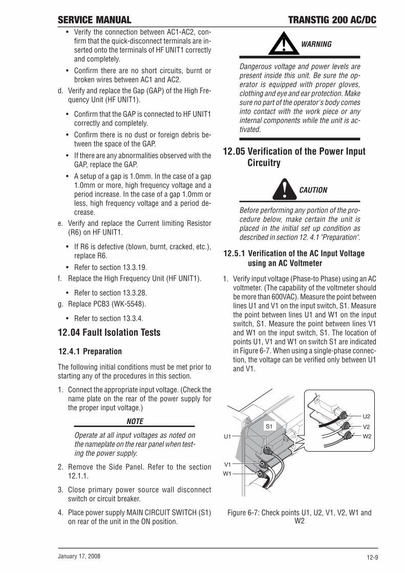
SERVICE MANUAL TRANSTIG 200 AC/DC
January 17, 2008 12-9
• Verify the connection between AC1-AC2, con-firm that the quick-disconnect terminals are in-serted onto the terminals of HF UNIT1 correctlyand completely.
• Confirm there are no short circuits, burnt orbroken wires between AC1 and AC2.
d. Verify and replace the Gap (GAP) of the High Fre-quency Unit (HF UNIT1).
• Confirm that the GAP is connected to HF UNIT1correctly and completely.
• Confirm there is no dust or foreign debris be-tween the space of the GAP.
• If there are any abnormalities observed with theGAP, replace the GAP.
• A setup of a gap is 1.0mm. In the case of a gap1.0mm or more, high frequency voltage and aperiod increase. In the case of a gap 1.0mm orless, high frequency voltage and a period de-crease.
e. Verify and replace the Current limiting Resistor(R6) on HF UNIT1.
• If R6 is defective (blown, burnt, cracked, etc.),replace R6.
• Refer to section 13.3.19.f. Replace the High Frequency Unit (HF UNIT1).
• Refer to section 13.3.28.g. Replace PCB3 (WK-5548).
• Refer to section 13.3.4.
12.04 Fault Isolation Tests
12.4.1 Preparation
The following initial conditions must be met prior tostarting any of the procedures in this section.
1. Connect the appropriate input voltage. (Check thename plate on the rear of the power supply forthe proper input voltage.)
NOTE
Operate at all input voltages as noted onthe nameplate on the rear panel when test-ing the power supply.
2. Remove the Side Panel. Refer to the section12.1.1.
3. Close primary power source wall disconnectswitch or circuit breaker.
4. Place power supply MAIN CIRCUIT SWITCH (S1)on rear of the unit in the ON position.
! WARNING
Dangerous voltage and power levels arepresent inside this unit. Be sure the op-erator is equipped with proper gloves,clothing and eye and ear protection. Makesure no part of the operator's body comesinto contact with the work piece or anyinternal components while the unit is ac-tivated.
12.05 Verification of the Power InputCircuitry
CAUTION
Before performing any portion of the pro-cedure below, make certain the unit isplaced in the initial set up condition asdescribed in section 12. 4.1 "Preparation".
12.5.1 Verification of the AC Input Voltageusing an AC Voltmeter
1. Verify input voltage (Phase-to Phase) using an ACvoltmeter. (The capability of the voltmeter shouldbe more than 600VAC). Measure the point betweenlines U1 and V1 on the input switch, S1. Measurethe point between lines U1 and W1 on the inputswitch, S1. Measure the point between lines V1and W1 on the input switch, S1. The location ofpoints U1, V1 and W1 on switch S1 are indicatedin Figure 6-7. When using a single-phase connec-tion, the voltage can be verified only between U1and V1.
S1
U1
V1
W1
V2
U2
W2
Figure 6-7: Check points U1, U2, V1, V2, W1 andW2

TRANSTIG 200 AC/DC SERVICE MANUAL
January 17, 200812-10
2. If the input voltage is out of the operating rangeof the unit, which is 10% (187 ~ 253 /414 ~ 506VAC) of the rated voltage (208, 230/ 460V), verifythe available power capacity at the installed site.If the input voltage is within the operating range,recheck the input voltage while welding, as weld-ing may cause the input voltage to decrease to avalue below the operating range of the unit.
3. Verify input voltage after the input switch (S1)using an AC voltmeter. (The capability of the volt-meter should be more than 600VAC.)
• Using an AC voltmeter, measure between thepoints U2 and V2 on the input switch, S1.
• Using an AC voltmeter, measure between thepoints U2 and W2 on the input switch, S1.
• Using an AC voltmeter, measure between thepoints V2 and W2 on the input switch, S1.
The location of points U2, V2 and W2 on switch S1are indicated in Figure 6-7. When using a single-phaseconnection, the voltage can be verified only betweenU2 and V2.
4. If this voltage is out of the operating range, whichis 10% (187~253/414~ 506VAC) of the rated volt-age (208, 230 / 460V), replace S1 following theprocess in section 13.3.26.
5. Verify the rectified output voltage of the input di-ode, D1 using a DC voltmeter. (The capability ofthe voltmeter should be more than 1000VDC.)Using a DC voltmeter, measure between the points1 (P) [+] and 2 (N) [-] on D1. Points 1 (P) and 2(N) are on D1. See Figure 12.8. The measuredvoltage should be approximately 1.4 times largerthan input voltage measured in #1 above. Replacediode D1 if the calculated measurement is notwithin the corresponding range (260 ~ 360 / 580~ 720 VDC) following the process in section13.3.30.
D1
1
2
Figure 6-8: The check points 1 (P) and 2 (N)
6. Verify bus voltage (the voltage of the electrolyticcapacitor after rectification) using a DC voltme-ter. (The capability of the voltmeter should be morethan 1000VDC.) Using a DC voltmeter, measurebetween the points TB1 (P) [+] and TB2 (N) [-] onPCB1 (WK-5477) Points TB1 (P) and TB2 (N) canbe found on the parts side of PCB1. See Figure 6-9. The measured voltage should be approximately1.4 times larger than input voltage measured in#1 above. Replace diode D1 if the calculated mea-surement is not within the corresponding range(260 ~ 360 / 580 ~ 720 VDC).
PCB1TB1TB2
Figure 6-9: The check points TB1(P) and TB2(N)
7. After the replacement of D1, if the above voltageis still abnormal, replace PCB1 (WK-5477).
12.5.2 Verification of Power Supply Voltage
CAUTION
Before performing any portion of the pro-cedure below, make certain the unit isplaced in the initial set up condition asdescribed in section 12. 4.1 "Preparation".
1. Verify Power Supply voltage using an DC voltme-ter. (The capability of the voltmeter should be morethan 50VDC.) Operate at all input voltages as notedon the nameplate on the rear panel when testingthe power supply.
2. On the PCB3 (WK-5548) and PCB6 (WK- 5549),measure the voltages according to the followingtable. The check points and the reference are ob-tainable on the top side of PCB6 (WK-5549). Thelocations of points are indicated in Figure 6-10,6-11.

SERVICE MANUAL TRANSTIG 200 AC/DC
January 17, 2008 12-11
TP1
TP2
TP3
TP0
PCB6
Figure 6-10: Checkpoints TP0-TP3 on PCB6
Check Point Reference ACCEPTABLEPCB3 PCB3 VALUE
Pin 1 on CN18 Pin 3 on CN18 +24VDC
Table 6-1: Checkpoints TP0-TP3 on PCB6
PCB3
CN18
pin 1pin 3
Figure 6-11: Checkpoints CN18 on PCB3
3. If any of these voltages are not present or are be-low a 10% tolerance, replace PCB3 (WK-5548).Refer to section 13.3.4.
12.5.3 Verification of the Cooling Fan, FAN1,Drive Circuitry
CAUTION
Before performing any portion of the pro-cedure below, make certain the unit isplaced in the initial set up condition asdescribed in section 12. 4.1 "Preparation".
1. Verify the condition of the cooling fan, FAN1, us-ing a DC voltmeter. (The capability of the voltme-ter should be more than 50VDC.) Using a DC volt-meter, measure between PIN 1 (Positive [+]) andPIN 2 (Negative [-]) of CN11 on PCB3 (WK-5548).The location of connector CN11 of PCB3 is indi-cated in Figure 6-12. When you measure the abovevoltage, do not remove the connector. Conductthe measurement while the connector plug andreceptacle are still connected.
PCB3
CN11
1pin2pin
Figure 6-12: Verification of the FAN1
2. Using the measurement taken above, follow thechart below for possible failure modes.
FAN1 Status
Voltage measurement. (1PIN-2PIN of
CN11 on PCB3)
Remedy
Case 1
Rotating DC 18 ~ 25V FAN1 drive circuit is normal.
Case 2
Rotating Below DC 18V Replace PCB3. Refer to section 12.3.4.
Case 3
Inactive Below DC 18V
Replace PCB3. Refer to section 12.3.4.4. Perform “2". Verfication of Power Supply Voltage” Refer to section 11.5.2.
Case 4 Inactive DC 18 ~ 25V
Replace the FAN1. Refer to section 12.3.24.
Table 6-3: Verification of the FAN1

TRANSTIG 200 AC/DC SERVICE MANUAL
January 17, 200812-12
• During low output and standby, fan rotationbecomes slower. Therefore, exact voltage mea-surement becomes impossible.
• When verifying the voltage, confirm that the ACinput voltage remains within the operating rangeof the unit (the AC input does not drop below180VAC).
12.5.4 Verification of the Gas Valve, SOL1,Drive Circuitry
CAUTION
Before performing any portion of the pro-cedure below, make certain the unit isplaced in the initial set up condition asdescribed in section 12. 4.1 "Preparation".
1. Verify the voltage between the PIN 3 (Positive [+])and PIN 4 (Negative [-]) of connector CN11 onPCB3 (WK-5548) while you press the torch switchwhile in TIG Mode. (The capacity of the voltmetershould be more than 50VDC.) The location of con-nector CN11 of PCB3 (WK- 5548) is indicated inFigure 6-13. When you measure the above volt-age, do not remove the connector. Conduct themeasurement while the connector plug and re-ceptacle are still connected.
PCB3
CN11
pin 3pin 4
Figure 6-13: Verification of the SOL1
2. Using the measurement taken above, follow thechart below for possible failure modes.
Voltage measurement.
(1PIN-2PIN of Remedy
CN11 on PCB3) Case 1 Below DC 18V
Replace PCB1. Refer to section 12.3.1.
Case 2 DC 18 ~ 25V Replace SOL1. Refer to section 12.3.25.
Table 6-4: Verification of the SOL1
3. When verifying the voltage, confirm that the ACinput voltage remain within the operating rangeof the unit. (The AC input does not drop below180VAC).
12.5.5 Verification of the primary Diode (D1)
CAUTION
Before performing any portion of the pro-cedure below, make certain the unit isplaced in the initial set up condition asdescribed in section 12. 4.1 "Preparation".
1. Verify the characteristic of the primary diode, D1,using a diode tester.
2. Refer to Table 6-5 and Figure 6-14 for the check-points on D1.
TERMINALS COMPONENT
TESTED Positive lead
Negative lead
ACCEPTABLE VALUE
3, 4, 5 0 0.3 to 0.5V 0 3, 4, 5 Open
Diode of D1 3, 4, 5 2 Open
2 3, 4, 5 0.3 to 0.5V Thyristor of
D1 0 1
1 0
Open Open
Table 6-5: Tester checkpoints for D1

SERVICE MANUAL TRANSTIG 200 AC/DC
January 17, 2008 12-13
6
7
345
2
1
0
0 6 7
1
2
5
4
3
Figure 6-14: Tester checkpoints for D1 and showingthe connection diagram
12.5.6 Verification of the secondary Diode(D2, D4, D5)
CAUTION
Before performing any portion of the pro-cedure below, make certain the unit isplaced in the initial set up condition asdescribed in section 12. 4.1 "Preparation".
1. Verify the characteristic of the secondary diode,D2, D4 and D5, using a diode tester.
2. Refer to Table 6-6 and Figure 6-15 for the check-points on D2, D4 and D5.
TERMINALS
COMPONENT TESTED Positive
lead Negative
lead
ACCEPTABLE VALUE
Diode 1 of D2, Anode Cathode 0.2 to 0.3V D4 and D5 Cathode Anode Open
Diode 2 of D2, Anode Cathode 0.2 to 0.3V D4 and D5 Cathode Anode Open
Table 6-6: Tester checkpoints for D2, D4 and D5
Anode Anode
Cathode Cathode
Figure 6-15: Tester checkpoints in D2, D4 and D5

TRANSTIG 200 AC/DC SERVICE MANUAL
January 17, 200812-14
12.5.7 Verification of the primary IGBT (Q1-Q12)
CAUTION
Before performing any portion of the pro-cedure below, make certain the unit isplaced in the initial set up condition asdescribed in section 12. 4.1 "Preparation".
1. Check whether there are any abnormalities in theappearance of PCB8 and PCB9.
2. Verify the characteristic of the primary IGBT (Q1-Q12), using a diode tester.
3. Refer to Table 6-7 and Figure 6-16 for the check-points on PCB8 and PCB9.
TERMINALS
COMPONENT TESTED Positive
lead Negative
lead
ACCEPTABLE VALUE
C 1 C2E1
C2E1 C1
Open 0.2 to 0.5V
Collector-Emitter of Q13 (by PCB15 connector)
C2E1 E2
E2 C2E1
Open 0.2 to 0.5V
Table 6-7: Tester checkpoints for Q1-Q12
C CE E
PCB8
PCB9
Figure 6-16: Tester checkpoints in the Q1-Q12
12.5.8 Verification of the secondary IGBT(Q13)
CAUTION
Before performing any portion of the pro-cedure below, make certain the unit isplaced in the initial set up condition asdescribed in section 12. 4.1 "Preparation".
1. Check whether there are any abnormalities on theappearance of PCB14.
2. Verify the characteristic of the secondary IGBT(Q13), using a diode tester.
3. Refer to Table 6-8 and Figure 6-17 for the check-points on Q13.
TERMINALS COMPONENT
TESTED Positive lead
Negative lead
ACCEPTABLE VALUE
C 1 C2E1
C2E1 C1
Open 0.2 to 0.5V
Collector-Emitter of Q13 (by PCB15 connector)
C2E1 E2
E2 C2E1
Open 0.2 to 0.5V
Table 6-8: Tester checkpoints for Q13
C1
E2
C2E1
Figure 6-17: Tester checkpoints in the Q13

SERVICE MANUAL TRANSTIG 200 AC/DC
January 17, 2008 12-15
12.5.9 Verification of No-load Voltage (OCV)
CAUTION
Before performing any portion of the pro-cedure below, make certain the unit isplaced in the initial set up condition asdescribed in section 12. 4.1 "Preparation".
1. Verify the no-load voltage in STICK mode.
a. In STICK welding mode, mark and then turnpotentiometer VR1 on PCB6 (WK-5549) allthe way to the right and turn off the electricshock protector function (Voltage-Reduction-Device, VRD).
b. Contactor function is put into the state of "ON"pushing Function button. Refer to section 12.
! WARNING
Electric shock hazard. The unit will gener-ate OCV immediately when contactor func-tion is put into the state of "ON pushingFunction button enabling STICK mode.
c. Verify the no-load voltage using a DC voltme-ter. (The capability of the voltmeter should bemore than 100VDC.)
d. The normal no-load voltage is approximately65V.
2. Verify the no-load voltage (OCV) in High FrequencyTIG mode.
! WARNING
This welding mode produces high fre-quency and high voltage. Extra care shallbe taken to prevent electric shock.
3. When in HF TIG mode, the unit will generate highvoltage. To prevent personal harm and test equip-ment damage, mark and then remove the indi-cated wire from the HF UNIT1 shown in Figure 6-18. To prevent electric shock, always wrap theremoved wire with electrical tape or other suit-able insulation.
Figure 6-18: Removal and installation from the HFUNIT1 (To disable the operation of the HF unit.)
4. Press the Welding mode selection button to se-lect HF TIG welding mode.
5. While depressing the Torch switch, verify the OCVusing a DC voltmeter. (The capability of the volt-meter should be more than 100VDC.) The checkpoint with a tester is the voltage between outputterminal + and -. In TIG mode, the OCV ceases 3seconds after you depress the torch switch.
6. The normal no-load voltage is approximately 58-62V.
7. Return the setting variable resister (VR1) to theoriginal position. (Return to the position recordedby "a. 1)" clause.)
• Fully clockwise: VRD ON
• Fully counterclockwise: VRD OFF8. Return connection with HF UNIT1 to the original
position.

TRANSTIG 200 AC/DC SERVICE MANUAL
January 17, 200812-16
THIS PAGE LEFT INTENTIONALLY BLANK

13 MAINTENANCEMAINTENANCE
1 Maintenance List
8
91
4
5
2
3
6
7
No. DWG No. Parts name Reference page Part No.
1 PCB3 Print Circuit Board (WK-5548) 13-9
2 PCB10 Print Circuit Board (WK-5527) 13-13
3 PCB11 Print Circuit Board (WK-5528) 13-13
4 PCB12 Print Circuit Board (WK-5615) 13-15
5 PCB13 Print Circuit Board (WK-5569) 13-18
6 PCB14 Print Circuit Board (WK-5570) 13-19
7 PCB16 Print Circuit Board (WK-5499) 13-19
8 PCB17 Print Circuit Board (WK-4917) 13-20
9 PCB18 Print Circuit Board (WK-5861) 13-21
SERVICE MANUAL TRANSTIG 200 AC/DC
January 17, 2008 13-1
W7001314
W7001812
W7001320
W7001594
W7001433
W7001434
W7001324
10-6740
W7001602

13 MAINTENANCE
3
6
7
25
4
8
1
No. DWG No. Parts name Reference page Part No.1 PCB1 Print Circuit Board (WK-5477) 13-6 W7001402
2 PCB2 Print Circuit Board (WK-5596) 13-7 W7001601
3 PCB4 Print Circuit Board (WK-4819) 13-10 10-6635
4 PCB5 Print Circuit Board (WK-5551) 13-10 W7001417
5 PCB6 Print Circuit Board (WK-5549) 13-10 W7001727
6 PCB7 Print Circuit Board (WK-5550) 13-11 W7001423
7 PCB8 (Q1~Q6) Print Circuit Board (WK-5479) (Primary IGBT) 13-11 W7001318
8 PCB9 (Q7~Q12) Print Circuit Board (WK-5479) (Primary IGBT) 13-12 W7001318
TRANSTIG 200 AC/DC SERVICE MANUAL
13-2 January 17, 2008

13 MAINTENANCE
9
546
3
12
1011
2
7
1
8
No. DWG No. Parts name Reference page Part No.
1 CC1 Coupling Coil 13-24 W7001384
2 CT2 Current Trans 13-15 W7001304
3 D1 Primary Diode 13-32 10-6628
4 D2 Secondary Diode 13-33 10-6629
5 D4 Secondary Diode 13-33 10-6629
6 D5 Secondary Diode 13-33 10-6629
7 FCH1 Reactor 13-31 W7001502
8 HCT1 Hall C. T. 13-25 10-5003
9 HF. UNIT High Freguency Unit 13-31 W7001399
10 L101 Reactor 13-35 W7001400
11 L103 Earth Inductance 13-35 W7001605
12 T1 Main Trans 13-15 W7001456
January 17, 2008 13-3
SERVICE MANUAL TRANSTIG 200 AC/DC
January 17, 2008 13-3
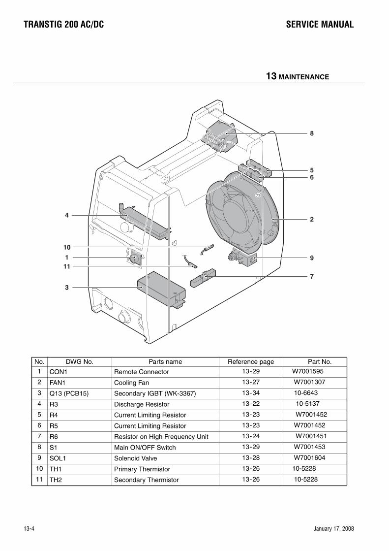
13 MAINTENANCE
8
65
9
7
24
11
10
1
3
No. DWG No. Parts name Reference page Part No.
1 CON1 Remote Connector 13-29 W7001595
2 FAN1 Cooling Fan 13-27 W7001307
3 Q13 (PCB15) Secondary IGBT (WK-3367) 13-34 10-6643
4 R3 Discharge Resistor 13-22 10-5137
5 R4 Current Limiting Resistor 13-23 W7001452
6 R5 Current Limiting Resistor 13-23 W7001452
7 R6 Resistor on High Frequency Unit 13-24 W7001451
8 S1 Main ON/OFF Switch 13-29 W7001453
9 SOL1 Solenoid Valve 13-28 W7001604
10 TH1 Primary Thermistor 13-26 10-5228
11 TH2 Secondary Thermistor 13-26 10-5228
13-4 January 17, 2008
TRANSTIG 200 AC/DC SERVICE MANUAL
13-4 January 17, 2008
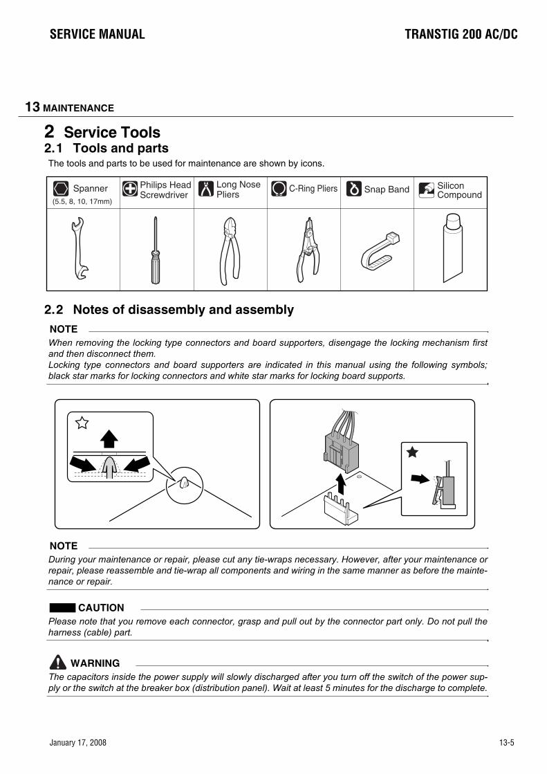
13 MAINTENANCE
2 Service Tools2.1 Tools and partsThe tools and parts to be used for maintenance are shown by icons.
2.2 Notes of disassembly and assemblyNOTEWhen removing the locking type connectors and board supporters, disengage the locking mechanism firstand then disconnect them.Locking type connectors and board supporters are indicated in this manual using the following symbols;black star marks for locking connectors and white star marks for locking board supports.
NOTEDuring your maintenance or repair, please cut any tie-wraps necessary. However, after your maintenance orrepair, please reassemble and tie-wrap all components and wiring in the same manner as before the mainte-nance or repair.
CAUTIONPlease note that you remove each connector, grasp and pull out by the connector part only. Do not pull theharness (cable) part.
WARNINGThe capacitors inside the power supply will slowly discharged after you turn off the switch of the power sup-ply or the switch at the breaker box (distribution panel). Wait at least 5 minutes for the discharge to complete.
C-Ring PliersLong NosePliers
Philips HeadScrewdriver
Spanner(5.5, 8, 10, 17mm)
Snap Band SiliconCompound
January 17, 2008 13-5
SERVICE MANUAL TRANSTIG 200 AC/DC
January 17, 2008 13-5

13 MAINTENANCE
3 Replacement Procedure3.1 PCB1 (WK-5477)
1) Remove the Side Panel. [Reference page: 11-1]
2) Remove the PCB18 (WK-5861). [Reference page: 12-21]
3) Remove PCB2 (WK-5596). [Reference page: 12-7]
4) Remove the PCB8 (WK-5479). [Reference page: 12-11]
5) Remove the PCB9 (WK-5479). [Reference page: 12-12]
6) Remove the four screws. Pull out the Rear Control Cover and bring it down.
7) Remove the five screws and the PCB1 (WK-5477). Remove the two screws and two terminals.
8) Remove the four screws and remove the four terminals and 200V Input Bus Bar.
1
11
1
2
11 1
2
3
1 11
222
2
3
3
13-6 January 17, 2008
TRANSTIG 200 AC/DC SERVICE MANUAL
13-6 January 17, 2008

13 MAINTENANCE
3.2 PCB2 (WK-5596) 1) Remove the Side Panel. [Reference page: 11-1]
2) Remove the PCB18 (WK-5861). [Reference page: 12-11]
3) Disconnect the 13 connectors.
4) Remove the four screws and two ground terminals.
5) Remove the PCB3, PCB4, PCB5, PCB6, and PCB7 unit and then disconnect the two connectors.
CN1 CN3
CN2
CN17
CN21
CN9CN8
CN7
CN11CN9
CN19
CN8CN1
January 17, 2008 13-7
SERVICE MANUAL TRANSTIG 200 AC/DC
January 17, 2008 13-7

13 MAINTENANCE
Remove the Insulated Sheet.
6) Remove the three screws and seven terminals. Remove the PCB2 (WK-5596).
7) Disconnect the three connectors and two terminal from the PCB2 (WK-5596).
1
2
2
3
CN15
CN14
1
2
1
11
2
CN1
CN2
CN3
TB5TB6
13-8 January 17, 2008
TRANSTIG 200 AC/DC SERVICE MANUAL
13-8 January 17, 2008

13 MAINTENANCE
3.3 PCB3 (WK-5548), PCB5 (WK-5551) 1) Remove the Side Panel. [Reference page: 11-1]
2) Remove PCB4 (WK-4819). [Reference page: 12-10]
3) Remove PCB6 (WK-5549). [Reference page: 12-10]
4) Remove PCB7 (WK-5550). [Reference page: 12-11]
5) Disconnect the 11 connectors.
6) Remove the four screws and then the two ground terminals. Remove the PCB3 and PCB5 unit.Disconnect the two connectors.
7) Disconnect the one connector and remove the two screws, and then remove the PCB5 (WK-5551) fromthe PCB3 (WK-5548). Remove the one screw and one ground terminal from the PCB5 (WK-5551).
CN23
CN19
CN11CN8
CN3CN2
CN1
CN9
CN22
CN21CN20
1
CN14CN15
2
1
2
CN20
January 17, 2008 13-9
SERVICE MANUAL TRANSTIG 200 AC/DC
January 17, 2008 13-9

13 MAINTENANCE
8) Disconnect the two connectors from the PCB3 (WK-5548).
3.4 PCB4 (WK-4819) 1) Remove the Side Panel. [Reference page: 11-1]
2) Remove the two screws and three connectors and remove the PCB4 (WK-4819). Disconnect the one connector.
3.5 PCB6 (WK-5549) 1) Remove the Side Panel. [Reference page: 11-1]
2) Disconnect the six connectors.
CN33
CN18
2CN4
1
CN6
CN5
CN4
CN21
CN20
CN8
CN9
CN17
CN1
13-10 January 17, 2008
TRANSTIG 200 AC/DC SERVICE MANUAL
13-10 January 17, 2008

13 MAINTENANCE
3) Remove the three screws and five connectors. Remove the PCB6 (WK-5549).
3.6 PCB7 (WK-5550) 1) Remove the Side Panel. [Reference page: 11-1]
2) Remove the PCB6 (WK-5549). [Reference page: 12-10]
3) Remove the two screws and three connectors. Remove the PCB7 (WK-5550).
3.7 PCB8 (WK-5479) (IGBT (Q1~Q6)) 1) Remove the Side Panel. [Reference page: 11-1]
2) Remove the four screws and two IGBT Chassis.
CN27
CN30CN31
CN32
CN18
CN32CN31
CN30
January 17, 2008 13-11
SERVICE MANUAL TRANSTIG 200 AC/DC
January 17, 2008 13-11

13 MAINTENANCE
3) Remove the two connectors and three screws. Remove the PCB8 (WK-5479).
Remember to install silicone rubber sheets when reinstalling the PCB8 (WK-5479).
3.8 PCB9 (WK-5479) (IGBT (Q7~Q12)) 1) Remove the Side Panel. [Reference page: 11-1]
2) Remove the four screws and two IGBT Chassis.
3) Remove the two connectors and three screws. Remove the PCB9 (WK-5479).
Remember to install silicone rubber sheets when reinstalling the PCB9 (WK-5479).
CN2CN1
CN2CN1
13-12 January 17, 2008
TRANSTIG 200 AC/DC SERVICE MANUAL
13-12 January 17, 2008
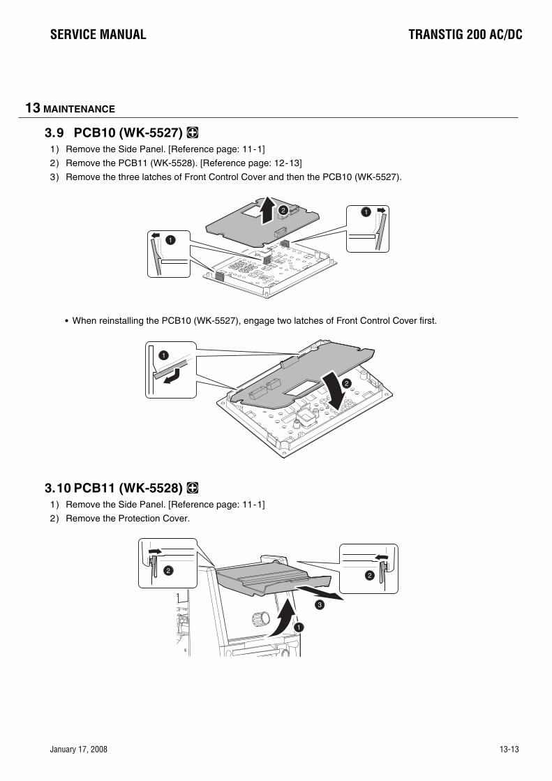
13 MAINTENANCE
3.9 PCB10 (WK-5527) 1) Remove the Side Panel. [Reference page: 11-1]
2) Remove the PCB11 (WK-5528). [Reference page: 12-13]
3) Remove the three latches of Front Control Cover and then the PCB10 (WK-5527).
When reinstalling the PCB10 (WK-5527), engage two latches of Front Control Cover first.
3.10 PCB11 (WK-5528) 1) Remove the Side Panel. [Reference page: 11-1]
2) Remove the Protection Cover.
1
12
2
1
1
22
3
January 17, 2008 13-13
SERVICE MANUAL TRANSTIG 200 AC/DC
January 17, 2008 13-13

13 MAINTENANCE
3) Remove the Knob Cap. Holding the Knob down, loosen the screw and remove the Knob.
4) Disconnect the one connector from the PCB10 (WK-5527). Remove the four screws. Pull out the Opera-tion Panel and bring it down.
5) Remove the one connector and two screws. Remove the PCB11 (WK-5528). Remove the Encoder Cover from the PCB11 (WK-5528).
1
2
3
1mm
2
2
2
23
CN21
1
2
3 CN1
4
13-14 January 17, 2008
TRANSTIG 200 AC/DC SERVICE MANUAL
13-14 January 17, 2008

13 MAINTENANCE
3.11 PCB12 (WK-5615), Transformer (T1), Current Trans (CT2) 1) Remove the Side Panel. [Reference page: 11-1]
2) Remove PCB13 (WK-5569). [Reference page: 12-18]
3) Disconnect the one connector and cut the one snap band.
4) Remove the one screw and one nut. Remove the two screws and remove the two terminals.
5) Open the Dust Cover Sheet. Remove the three screws and three terminals.
CN7
1
23
1
2
2
2
January 17, 2008 13-15
SERVICE MANUAL TRANSTIG 200 AC/DC
January 17, 2008 13-15

13 MAINTENANCE
6) Remove the 16 screws.
7) Remove the PCB12 and T1 unit.
8) Cut the one snap band and remove the Current Trans (CT2).
1
2
13-16 January 17, 2008
TRANSTIG 200 AC/DC SERVICE MANUAL
13-16 January 17, 2008

13 MAINTENANCE
9) Remove the Dust Cover Sheet. Extend the electrode and remove the T-D Bus Bar1, T-D Bus Bar2 and TCenter Bus Bar.
10) Remove the two PCB supporters and cushion. Remove the four screws and remove the Main Trans (T1).
1
2
2
3
1
1
2
3
4
January 17, 2008 13-17
SERVICE MANUAL TRANSTIG 200 AC/DC
January 17, 2008 13-17

13 MAINTENANCE
3.12 PCB13 (WK-5569) 1) Remove the Side Panel. [Reference page: 11-1]
2) Remove the Nylon Hose. Remove the four screws. Remove the two terminals and open the Rear Panel.
3) Disconnect the six connectors and remove the two screws and two terminals.
4) Remove the two screws and two PCB supporters and remove the PCB13 (WK-5569).
1
2
1
2
3
4
CN1
CN2
CN4
CN6CN3
CN5
13-18 January 17, 2008
TRANSTIG 200 AC/DC SERVICE MANUAL
13-18 January 17, 2008

13 MAINTENANCE
3.13 PCB16 (WK-5499) 1) Remove the Side Panel. [Reference page: 11-1]
2) Remove the Nylon Hose.
3) Disconnect the two connectors. Remove the three PCB supporters and remove the PCB16 (WK-5499).
3.14 PCB14 (WK-5570) 1) Remove the Side Panel. [Reference page: 11-1]
2) Remove the PCB16 (WK-5499). [Reference page: 12-19]
3) Remove the five screws and three terminals and remove the PCB14 (WK-5570).
2
1
CN1
CN3
1
1
2
1
1
1
1
22
2
3
January 17, 2008 13-19
SERVICE MANUAL TRANSTIG 200 AC/DC
January 17, 2008 13-19

13 MAINTENANCE
4) Remove the three PCB supporters from the PCB14 (WK-5570).
3.15 PCB17 (WK-4917) 1) Remove the Side Panel. [Reference page: 11-1]
2) Remove the four screws and four terminals.
3) Remove the four screws and then open the Rear Board.
1
1
2
2
1
11
1
2
13-20 January 17, 2008
TRANSTIG 200 AC/DC SERVICE MANUAL
13-20 January 17, 2008

13 MAINTENANCE
4) Disconnect the one connector. Remove the two screws and one ground terminal and remove the PCB17 unit.
5) Remove the two screws and remove the S1 Bus Bar from the PCB17 (WK-4917).
3.16 PCB18 (WK-5861)1) Remove the Side Panel. [Reference page: 11-1]
2) Remove the four screws and then remove the four cables.Remove the two screws. Remove the PCB18(WK-5861).
1
2
2
3
4
CN1
1
2
1
1
2
2
January 17, 2008 13-21
SERVICE MANUAL TRANSTIG 200 AC/DC
January 17, 2008 13-21

13 MAINTENANCE
3.17 Discharge Resistor (R3)1) Remove the Side Panel. [Reference page: 11-1]
2) Remove the Nylon Hose. Remove the two bolts, two toothed washers, one washer, and one terminal.
3) Remove the four screws and open the Front Panel.
4) Cut the one snap band and disconnect the one connector.
2
1
1
2
2
3
1
1
1
1
2
1
2 CN5
13-22 January 17, 2008
TRANSTIG 200 AC/DC SERVICE MANUAL
13-22 January 17, 2008

13 MAINTENANCE
5) Remove the one screw and one nut and remove the one terminal.
6) Remove the two screws and remove the Discharge Resistor (R3).
3.18 Current Limiting Resistor (R4, R5)1) Remove the Side Panel. [Reference page: 11-1]
2) Remove the PCB18 (WK-5861). [Reference page: 12-21]
3) Remove the PCB2 (WK-5596). [Reference page: 12-7]
4) Remove the one screw and remove the Current Limiting Resistor (R4, R5).
1
1
2
January 17, 2008 13-23
SERVICE MANUAL TRANSTIG 200 AC/DC
January 17, 2008 13-23

13 MAINTENANCE
3.19 Resistor on High Frequency Unit (R6) 1) Remove the Side Panel. [Reference page: 11-1]
2) Cut the one snap band and remove the two terminals. Remove the one screw and remove the Resistoron High Frequency Unit (R6).
3.20 Coupling Coil (CC1) 1) Remove the Side Panel. [Reference page: 11-1]
2) Remove the Nylon Hose. Remove the two bolts, two toothed washers, one washer, and one terminal.
3) Remove the four screws and open the Front Panel.
1
2
3
4
2
1
1
2
2
3
1
1
1
1
2
13-24 January 17, 2008
TRANSTIG 200 AC/DC SERVICE MANUAL
13-24 January 17, 2008

13 MAINTENANCE
4) Remove the two terminals. Remove the one screw and two terminals.
5) Remove the one screw and one nut. Remove the one screw and Coupling Coil (CC1).
3.21 Reactor (FCH1) 1) Remove the Side Panel. [Reference page: 11-1]
2) Remove the PCB16 (WK-5499). [Reference page: 12-19]
3) Remove the PCB14 (WK-5570). [Reference page: 12-19]
4) Remove the Coupling Coil (CC1). [Reference page: 12-24]
5) Remove the two posts, two screws and two nuts.
11
2
1
1
2
3
January 17, 2008 13-25
SERVICE MANUAL TRANSTIG 200 AC/DC
January 17, 2008 13-25

13 MAINTENANCE
6) Remove the four screws and remove the Reactor (FCH1). Remove the Insulating Sheet.
3.22 Primary Thermistor (TH1) 1) Remove the Side Panel. [Reference page: 11-1]
2) Cut the three snap bands. Disconnect the one connector. Remove the one screw and then detach the Primary Thermistor (TH1).
Before installing a new therminstor, apply a uniform coat of silicone compound (Shinetsu Silicone G-747 or equivalent) on the base.
3.23 Secondary Thermistor (TH2) 1) Remove the Side Panel. [Reference page: 11-1]2) Remove the PCB13 (WK-5569). [Reference page: 12-18]3) Remove the PCB12 (WK-5615). [Reference page: 12-15]4) Remove the one screw and one nut and remove the bus bar.
1
1
2
3
CN8
13-26 January 17, 2008
TRANSTIG 200 AC/DC SERVICE MANUAL
13-26 January 17, 2008

13 MAINTENANCE
5) Cut the four snap bands. Disconnect the one connector. Remove the one screw and then detach the Secondary Thermistor (TH2).
Before installing a new therminstor, apply a uniform coat of silicone compound (Shinetsu Silicone G-747 or equivalent) on the base.
3.24 Cooling Fan (FAN1) 1) Remove the Side Panel. [Reference page: 11-1]
2) Remove the Nylon Hose. Remove the four screws. Remove the two terminals and open the Rear Panel.
3) Cut the four snap bands and disconnect the one connector.
CN9
1
2
1
2
3
4
CN11
January 17, 2008 13-27
SERVICE MANUAL TRANSTIG 200 AC/DC
January 17, 2008 13-27

13 MAINTENANCE
4) Remove the two screws and detach the Cooling Fan (FAN1).
Do not have the wrong direction of the fan when reinstalling.
3.25 Solenoid Valve (SOL1) 1) Remove the Side Panel. [Reference page: 11-1]
2) Remove the Nylon Hose. Remove the four screws. Remove the two terminals and open the Rear Panel.
3) Remove the C-ring and detach the Solenoid Valve (SOL1).
When reinstalling, make sure that the C-ring seats in the solenoid valve groove.
AIR FLOW
RO
TAT
ION
1
2
1
2
3
4
1
2
13-28 January 17, 2008
TRANSTIG 200 AC/DC SERVICE MANUAL
13-28 January 17, 2008

13 MAINTENANCE
3.26 Main ON/OFF Switch (S1) 1) Remove the Side Panel. [Reference page: 11-1]
2) Remove the four screws and four terminals.
3) Remove the two screws and detach the Main ON/OFF Switch (S1). Remove the two posts.
3.27 Remote Connector (CON1) 1) Remove the Side Panel. [Reference page: 11-1]
2) Remove the Protection Cover.
1
1
2
2
1
22
3
January 17, 2008 13-29
SERVICE MANUAL TRANSTIG 200 AC/DC
January 17, 2008 13-29

13 MAINTENANCE
3) Remove the four screws. Pull out the Front Control Cover and bring it down.
4) Disconnect the two connectors. Remove the one screw and two ground terminals.
5) Remove the two screws and Remote Socket (CON1).
1
11
1
2
2
1CN15
CN14
1
1
2
13-30 January 17, 2008
TRANSTIG 200 AC/DC SERVICE MANUAL
13-30 January 17, 2008

13 MAINTENANCE
3.28 High Freguency Unit (HF.UNIT1) 1) Remove the Side Panel. [Reference page: 11-1]
2) Remove the High Freguency Gap. Remove the six terminals.
3) Remove the two screws, two washers and detach the High Freguency Unit (HF. UNIT1).
3.29 Hall C.T. (HCT1) 1) Remove the Side Panel. [Reference page: 11-1]
2) Remove the Nylon Hose. Remove the four screws. Remove the two terminals and open the Rear Panel.
1
1
2
1
2
1
2
3
4
January 17, 2008 13-31
SERVICE MANUAL TRANSTIG 200 AC/DC
January 17, 2008 13-31

13 MAINTENANCE
3) Remove the one screw and one nut. Disconnect the one connector.
4) Remove the one screw. Remove the Hall C. T. (HCT1) while slighty pressing down the bus bar.
3.30 Primary Diode (D1) 1) Remove the Side Panel. [Reference page: 11-1]
2) Remove the PCB18 (WK-5861). [Reference page: 12-21]
3) Remove the PCB2 (WK-5596). [Reference page: 12-7]
4) Remove the two screws and four terminals. Remove the two screws and then detach the Primary Diode(D1).
Before installing a new diode, apply a uniform coat of silicone compound (Shinetsu Silicone G-747 or equivalent) on the base.
CN1
1
1
2
1
2
3
1
2
13-32 January 17, 2008
TRANSTIG 200 AC/DC SERVICE MANUAL
13-32 January 17, 2008

13 MAINTENANCE
3.31 Secondary Diode (D2, D4, D5) 1) Remove the Side Panel. [Reference page: 11-1]
2) Remove the PCB13 (WK-5569). [Reference page: 12-18]
3) Remove the PCB12 (WK-5615). [Reference page: 12-15]
4) Remove the two screws and two nuts and remove the bus bar.
5) Remove the six screws and then detach the Secondary Diode (D2, D4, D5).
Do not have the wrong direction of the diodes when reinstalling.Before installing a new diode, apply a uniform coat of silicone compound (Shinetsu Silicone G-747 or equivalent) on the base.
January 17, 2008 13-33
SERVICE MANUAL TRANSTIG 200 AC/DC
January 17, 2008 13-33

13 MAINTENANCE
3.32 Secondary IGBT (Q13) (PCB15 (WK-3367)) 1) Remove the side cover. [Reference page: 11-1]
2) Remove the PCB16 (WK-5499). [Reference page: 12-19]
3) Remove the PCB14 (WK-5570). [Reference page: 12-19]
4) Remove the one bolt and remove the one toothed washer, one washer and one terminal.
5) Remove the three posts, bus bar and two terminals.
6) Remove the one connector and two screws and remove the Secondary IGBT (Q13).
Before sinstalling a new IGBT, apply a uniform coat of silicone compound (Shinetsu Silicone G-747 or equivalent) on the base.
CN1
13-34 January 17, 2008
TRANSTIG 200 AC/DC SERVICE MANUAL
13-34 January 17, 2008

13 MAINTENANCE
3.33 Reactor (L101) 1) Remove the Side Panel. [Reference page: 11-1]
2) Remove the Earth Inductance (L103). [Reference page: 12-35]
3) Remove the two screws and two cables.
4) Cut the snap band. Open the Reactor (L101) and Remove the Reactor (L101).
3.34 Earth Inductance (L103) 1) Remove the Side Panel. [Reference page: 11-1]
2) Remove the nut and then remove the two ground cables from the Rear Control Cover.
1
2
1
2
1
2
January 17, 2008 13-35
SERVICE MANUAL TRANSTIG 200 AC/DC
January 17, 2008 13-35

13 MAINTENANCE
3) Remove the two screws and the nut. Remove the Earth Inductance (L103).
1
1
12
13-36 January 17, 2008
TRANSTIG 200 AC/DC SERVICE MANUAL
13-36 January 17, 2008

THIS PAGE LEFT INTENTIONALLY BLANK
January 17, 2008 13-37
SERVICE MANUAL TRANSTIG 200 AC/DC
January 17, 2008 13-37

APPENDIX 1 PARTS LIST1 Equipment IdentificationAll identification numbers as described in the Introduction chapter must be furnished when ordering parts ormaking inquiries. This information is usually found on the nameplate attached to the equipment. Be sure toinclude any dash numbers following the Specificazztion or Assembly numbers.
2 How To Use This Parts ListThe Parts List is a combination of an illustration and a corresponding list of parts which contains a break-down of the equipment into assemblies, subassemblies, and detail parts. All parts of the equipment are listedexcept for commercially available hardware, bulk items such as wire, cable, sleeving, tubing, etc., and per-manently attached items which are soldered, riveted, or welded to other parts. The part descriptions may beindented to show part relationships. To determine the part number, description, quantity, or application of anitem, simply locate the item in question from the illustration and refer to that item number in the correspond-ing Parts List.TRANSTIG 200 AC/DC 700719
No. DWG No. Part No. Description Type & Rating QTY.1 CC1 W7001384 Coupling Coil, gen 3.1, IPS F3A040600 200A CC 12 CON1 W7001595 Post, Output, gen 3.1, IPS 206433-1 8P (with Wiring Assembly) 13 CT2 W7001304 Transformer, gen 3.1, IPS F2A503001 CT 1:40 14 D1 10-6628 Diode, gen 3.1, IPS DFA50BA160 15 D2 10-6629 Diode, gen 3.1, IPS DBA200UA60 16 D4 10-6629 Diode, gen 3.1, IPS DBA200UA60 17 D5 10-6629 Diode, gen 3.1, IPS DBA200UA60 18 FAN1 W7001307 Fan, gen 3.1, IPS 109E5724H507 DC 24V 16.8W 19 FCH1 W7001502 Inductor, gen 3.1, IPS F3A285101 AC/DC FCH 110 HCT1 10-5003 Sensor, Current, gen 3.1, IPS HC-TN200V4B15M 200A 4V 111 HF.UNIT1 W7001399 HF, Unit, gen 3.1, IPS HF.UNIT (WK-4840 U04) 112 10-6633 HF, Gap, gen 3.1, IPS U0A601100 113 L101 W7001400 Reactor, gen 3.1, IPS ZCAT-3035-1330 114 L103 W7001605 Inductor, earth, gen 3.1, IPS SNG-25B-600 115 PCB1 W7001402 PCB, gen 3.1, IPS WK-5477 U01 MAIN_PCB 116 PCB2 W7001601 PCB, gen 3.1, IPS WK-5596 U02 CVM CONTROL PCB 117 PCB3 W7001314 PCB, gen 3.1, IPS WK-5548 U01 DDC PCB 118 PCB4 10-6635 PCB, gen 3.1, IPS WK-4819 U01 DETECT PCB 119 PCB5 W7001417 PCB, gen 3.1, IPS WK-5551 U01 CONECT PCB 120 PCB6 W7001727 PCB, gen 3.1, IPS WK-5549 U07-1 200A CTRL PCB 121 PCB7 W7001423 PCB, gen 3.1, IPS WK-5550 U01 FILTER PCB 122 PCB8-9 W7001318 PCB, gen 3.1, IPS WK-5479 U01 GATE PCB (with 223 PCB10 W7001812 PCB,WK5527 U13,GEN3.1,IPS WK-5527 U13 PANEL PCB 124 PCB11 W7001320 PCB, gen 3.1, IPS WK-5528 U01 ENCODER PCB 125 PCB12 W7001594 PCB, gen 3.1, IPS WK-5615 U01 DIODE SNUBBER PCB 126 PCB13 W7001433 PCB, gen 3.1, IPS WK-5569 U01 GATE/INPOSE PCB 127 PCB14 W7001434 PCB, gen 3.1, IPS WK-5570 U01 IGBT SNUBBER PCB 128 PCB16 W7001324 PCB, gen 3.1, IPS WK-5499 U01 FILTER PCB 129 PCB17 10-6740 PCB, gen 3.1, IPS WK-4917 U04 INPUT FILTER PCB 130 PCB18 W7001602 PCB, gen 3.1, IPS WK-5861 CE FILTER PCB 131 Q13 10-6643 Transistor, gen 3.1, IPS GCA200CA60 (with WK-3367 U04) 132 R2 W7001449 Resistor, gen 3.1, IPS ERG3SJ220H 3W 22Ω 233 R3 10-5137 Resistor, gen 3.1, IPS JG23V101J 68W 100Ω 2
A-1 January 17, 2008
TRANSTIG 200 AC/DC SERVICE MANUAL
A-1 January 17, 2008

.YTQgnitaR&epyTnoitpircseD.oNtraP.oNGWD.oN34 R4-5 W7001452 Resistor, gen 3.1, IPS MHS20A221KI 20W 220Ω 135 R6 W7001451 Resistor, gen 3.1, IPS MHS20A101KI 20W 100Ω 136 S1 W7001453 Switch, gen 3.1, IPS DCP-52SR50C-480V 2P-480V (185ACDC) 137 SOL1 W7001604 Solenoid Valve, gen 3.1, IPS 5505NBR1.5 DC24V 11VA/10W (with Gas
Inlet and PC4-02)1
38 T1 W7001456 Transformer, gen 3.1, IPS F3A063501 200A MAIN TR 139 TH1, 2 10-5228 Thermistor, gen 3.1, IPS ERTA53D203 20kΩ/25°CB=3950K 2
1103500D0ESPI,1.3neg,tnorF,lenaP5641007W041105500D0ESPI,1.3neg,raeR,lenaP6641007W142704500D0ESPI,1.3neg,ediS,lebaL7641007W24
1 000643C0E SPI ,1.3 neg ,revoc ,esaC1331007W3444 W7001584 Cover, Rear, gen 3.1, IPS JDA173200 (200ACDC) 1
1002303C0ESPI,1.3neg,rotcetorP,revoC8951007W541004415ABESPI,1.3neg,redocnE,revoC1976-01641)teehSrevoctsuDhtiw(006735B1ESPI,1.3neg,BCP,revoC74
48 W7001600 Label, Name, gen 3.1, IPS N4A932900 (200ACDC) 12002587A4NSPI,1.3neg,ediS,lebaL8331007W941007920B1NSPI,1.3neg,gninraW1,lebaL9331007W051008920B1NSPI,1.3neg,gninraW2,lebaL0431007W15
1 006076A4NSPI ,1.3 neg mret tuptuo ,lebaL 5161007W251007040A4NSPI,1.3neg,tupnIsaG,lebaL3376-01351001919A4NSPI,1.3neg,DRV,lebaL5431007W45
55 W7001603 Outlet, Gas, gen 3.1, IPS EDA268800 (with PC4-02) 12SPI,1.3neg,gniR-C4815-0165
2 S07-53EB-KARTSPI ,1.3 neg ,F tuptuO ,lanimreT 0666-017558 N/A Cable, Input, gen 3.1, IPS 132"10/3SOWBLKW/R650 (185ACDC) 1
1008540ABESPI,1.3neg,tupnI,pmalC2666-01952009968B1ESPI,1.3neg,knistaeH4751007W061000078B1ESPI,1.3neg,knistaeH5751007W164001058B1ESPI,1.3neg,TBGI,pilCgnirpS1531007W261004710B5JSPI,1.3neg,1BCP,sissahC3851007W361005653C3JSPI,1.3neg,sissahC2851007W4613061262SPI,1.3neg,bonK5666-015614011203SPI,1.3neg,paCbonK6666-01661002610B1NSPI,1.3neg,rotcetorP,revoC5851007W76
4 007722ADESPI ,1.3 neg ,rebbur ,teehS 7531007W863)5M-5M(006346ABESPI,1.3neg,)5M(1,tsoP8531007W961005978ACESPI,1.3neg,L-D1,raBsuB6751007W071006978ACESPI,1.3neg,L-D2,raBsuB7751007W171002788ACESPI,1.3neg,D-T1,raBsuB8751007W271003788ACESPI,1.3neg,D-T2,raBsuB372000123ACESPI,1.3neg,1S,raBsuB8686-01471004109ACESPI,1.3neg,raBsuB0161007W571002409ACESPI,1.3neg,CC-T,raBsuB1161007W671004220ADESPI,1.3neg,T,raBsuB2161007W772001960ADESPI,1.3neg,raBsuB3161007W872000278B1ESPI,1.3neg,draoBdetalusnI9631007W971005958B1ESPI,1.3neg,teehSnoitalusnI7061007W081000471ADESPI,1.3neg,teehSnoitalusnI4161007W18
SERVICE MANUAL TRANSTIG 200 AC/DC
January 17, 2008 A-2
PARTS LIST

PARTS LIST
50
49
47
42
84
36
44
29
69
69 74
74
59
58
134156
538 54
37
42
85
52
575657 2
40
48
45
24
2343
67
6566
46
51
4955
No. DWG No. Part No. Description Type & Rating QTY.82 W7001616 Sheet, dust cover F, gen 3.1, IPS E1B935200 183 W7001609 Sheet, dust cover R, gen 3.1, IPS E1B935600 184 W7001374 Clip, gen 3.1, IPS #74 NATURAL 4 485 W7001618 Hose, Nylon, gen 3.1, IPS T0425B Nylon Hose L=0.5m 186 10-2020 Plug, Output, gen 3.1, IPS TRAK-SK50 187 300X4903 Operating Manual, gen 3.1, IPS Operating Manual 1
A-3 January 17, 2008
TRANSTIG 200 AC/DC SERVICE MANUAL
A-3 January 17, 2008

PARTS LIST
39
56
7
25
20
19
2118
17
81
14
2262
62
62
622268
68
16
15
80
63
4
3434
33
10
64
1132
12
38
83
35
3961
76
60
60
79
79
8279
64
9
31
75
1
27
71
70
77 73
72
2628
79 30
3
78
January 17, 2008 A-4
SERVICE MANUAL TRANSTIG 200 AC/DC
January 17, 2008 A-4

APPENDIX 2 CONNECTION WIRING GUIDEAPPENDIX 2 Connection Wiring Guide
CONNECTION WIRING GUIDE
Destination
A PCB2 CN2 PCB3 CN3
B PCB2 CN3 D1
C PCB3 CN1 D1
D PCB3 CN2 PCB17 CN1
E PCB3 CN7 CT2
FPCB3 CN11
FAN1
G SOL1
H PCB3 CN20 PCB8 CN1
I PCB3 CN21 PCB8 CN2
J PCB3 CN22 PCB9 CN1
K PCB3 CN23 PCB9 CN2
L PCB3 CN18 PCB7 CN20
M PCB3 CN33 PCB6 CN20
N PCB6 CN1 HCT1
O PCB6 CN8 TH1
P PCB6 CN9 TH2
Q PCB6 CN17PCB13 CN4
PCB16 CN3
R PCB6 CN21 PCB10 CN2
SPCB7
CN14CON1
T CN15
U PCB10 CN1 PCB11 CN1
V PCB13 CN6 PCB15 CN1
A-5 January 17, 2008
TRANSTIG 200 AC/DC SERVICE MANUAL
A-5 January 17, 2008

CONNECTION WIRING GUIDE
PCB10
PCB9
PCB8
PCB11
PCB7
PCB6
PCB4
PCB3
PCB2
HCT1
PCB13
PCB16
CN2
CN1
CN2
CN1
CN1CN20
CN8CN9
CN33
CN21CN17
CN1
CN22
CN11
CN23
CN20
CN14
CN15
CON1
CN3
CN20
CN21
CN1
CN2
CN3
CN4
TH1
TH2
CN3
D1
PCB17
FAN1
SOL1
CN1
CN2
CN1
CT2
CN7 CN18
PCB15
CN6
CN1
CN2
V
Q
A
B
C
H
J
M
N
R
S
T
U
P
O
L
K I
E
G
FD
January 17, 2008 A-6
SERVICE MANUAL TRANSTIG 200 AC/DC
January 17, 2008 A-6

APPENDIX 3 DIODE TESTING BASICSAPPENDIX 4 DIODE TESTING BASIC
DIODE TESTING BASIC
Testing of diode modules requires a digital Volt/Ohmmeter that has a diode test scale.Locate thediode module to be tested.Remove cables frommounting studs on diodes to isolate them within themodule.Set the digital volt/ohm meter to the diodetest scale.Using figure 1 and 2, check each diodein the module. Each diode must be checked in boththe forward bias (positive to negative) and reversebias (negative to positive) direction.
1. To check the diode in the forward bias direc-tion, connect the volt/ohm meter positive lead to the anode (positive, +) of the diode and the negative lead to the cathode (negative, –) of the diode (refer to Figure 13-1 . A properly functioning diode will conduct in the forward bias direction, and will indicate between 0.3 and 0.9 volts.
2. To check the diode in the reverse bias direc-tion, reverse the meter leads (refer to Figure 13-1). A properly functioning diode will block current flow in the reverse bias direction, and depending on the meter function, will indicate an open or "OL".
3. If any diode in the module tests as faulty, replace the diode module.
4. Reconnect all cables to the proper terminals.
Figure 13-1: Forward bias diode test
Figure 13-2: Reverse bias diode test
COM AVR
Anode Cathode
Forward BiasDiode Conducting
COM AVR
AnodeCathode
Reverse BiasDiode Not Conducting
A-7 January 17, 2008
TRANSTIG 200 AC/DC SERVICE MANUAL
A-7 January 17, 2008

January 17, 2008 A-8
SERVICE MANUAL TRANSTIG 200 AC/DC
APPENDIX 4: TRANSTIG 200 AC/DC ACCESSORIES
Description Part No. Details 17 Series air cooled TIG torch (suitable for TransTig 200Pi)
518710402 TIG torch with 4 metre cable & remote current control
26 Series air cooled TIG torch 538720401 TIG torch with 4 metre cable & remote current control
200 Amp lead set, 5 metre 646323 1 x 5m work lead; 1 x 5m electrode holder
400 Amp lead set, 8 metre 646325 1 x 8m work lead; 1 x 8m electrode holder OTD 10/4013 200Pi, 200AC/DC slider only OTD 10/2004 300Pi, 300AC/DC, 400i slider only OTD 10/4014 200Pi, 200AC/DC hand pendant only OTD 10/2005 300Pi, 300AC/DC, 400i hand pendant only OTD 10/4016 200Pi, 200AC/DC OTD 10/2007 300Pi, 300AC/DC, 400i
CIGWELD COMET argon regulator 301527 Regulator only CIGWELD COMET argon flowmeter 0-15 lpm 301710 Flowmeter only CIGWELD COMET argon flowmeter 10-40 lpm 301711 Flowmeter only CIGWELD COMET argon regulator/flowmeter 301526 Regulator/flowmeter only VAF-4 Wirefeeder (for 400i ONLY) 705700 VAF-4 wirefeeder, 8m interconnection,
operating manual VS212 Voltage sensing wirefeeder W3512006 VS212 wirefeeder, operating manual Tweco® 4 MIG Torch 717201 MIG torch with 3.6m cable, T4 connection ArcMaster Pro Auto-darkening Helmet, 9-13 – blue
454294 Welding helmet, 2 x spare cover lenses, product bag, operating manual
ArcMaster Pro Auto-darkening Helmet, 9-13 – blue with graphic
454295 Welding helmet, 2 x spare cover lenses, product bag, operating manual
ArcMaster Pro Auto-darkening Helmet, 9-13 – black with graphic
454296 Welding helmet, 2 x spare cover lenses, product bag, operating manual
Slide controller
Hand pendant
Foot controller

A-2 January 17, 2008
TRANSTIG 200 AC/DC SERVICE MANUAL
APPENDIX 5: TRANSTIG 200 AC/DC INTERCONNECTION DIAGRAM
CN130CN131CN131 CN130
CN132CN132
S1
Ground
PCB17Filter
Circuit Board[WK-4917]
CN
2
12
+
-
(1)
(2)
(0)
K(7)
G(6)
R(3)
S(4)
T(5)
D1
PCB2Link
Circuit Board[WK-5482]
CN1
1 2 345
P
R2
N
Q1C
GE
Q2C
GE
Q3C
GE
Q4C
GE
Q5C
GE
Q6C
GE
PCB8IGBT Gate
Circuit Board[WK-5479]
Q7C
GE
Q8C
GE
Q9C
GE
Q10C
GE
Q11C
GE
Q12C
GE
PCB9IGBT Gate
Circuit Board[WK-5479]
CN
2
1234
CN
112
CN
2
1234
PCB4Detect
Circuit Board[WK-4819]
CN
4
1234
CN1CN6CN5CN5 CN6 CN4
+-FAN1
N
P
R2
N
P
R2
TB1
TB2TB2
TB5
TB3
TB4
G2E2
G1E1
G4E4
G3E3
G4
E4PCB3Control SouceCircuit Board[WK-5548]
PCB1Main
Circuit Board[WK-5493]
3
CN
1123
PCB6Control
Circuit Board[WK-5549]
CT2CT1
SIDE CHASSIS 1
+
REARPANEL
E
EA
CN
312
G1
E1 G2
E2 G3
E3
PCB5Connect Circuit Board
[WK-5551]
CN30CN31CN31 CN30
CN32CN32
PCB7Filter
Circuit Board[WK-5550]
CN1
1 2 3
CN3
1 2 3 4 5
CN2
1 2 3
CN
1
123456
CN
11
1234
CN20
1 2 3 4 5 6
CN21
1 2 3 4 5 6 7
CN22
1 2 3 4 5 6
CN23
1 2 3 4 5 6 7
12
CN
7
34
R4
R5
12
CN
17 34
12
CN
21
34
12
CN
1
34
567
TB0
CN17CN17
CN18CN18
CN27CN27 C
N15
12345
12 C
N14
1 : Chassis Ground2 : Contactor Control/+24VDC3 : Contactor Control/GND4 : Not Used5 : Potentiometer Maximum6 : Potentiometer Minimum(GND)7 : Amperage Control Wiper 0-10VDC8 : Not Used
CN
20 123
1 2 3
CN33TH2 TH1
1 2 3
CN19
PGN
DP+
21V
1 2 3
CN18
EA
12
CN
17 34
12
CN
21
34
12
CN
1
34
567
1 2
CN20
1 2 3
CN9
1 2
CN8
SOL1
TB6
123
678
45
EA
CON1
C2E
E1C
C2E
E1C
L101
L103
PCB18CE Filter
Circuit Board[WK-5861]
TB5
TB1
TB2 TB4
TB3
SIDE CHASSIS 2
Ground
EA
TB0
EA
+
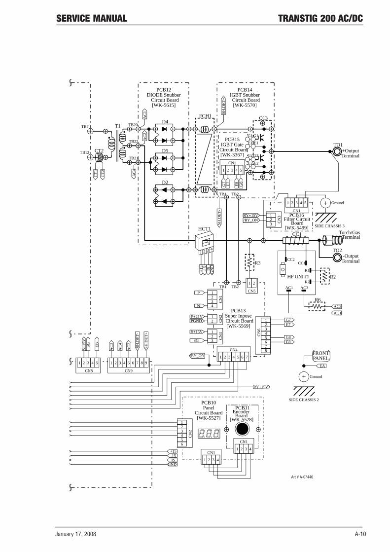
January 17, 2008 A-10
SERVICE MANUAL TRANSTIG 200 AC/DC
TB7
TB12TB21
TB22
TB20
CT2
PCB12DIODE Snubber
Circuit Board[WK-5615]
PCB10Panel
Circuit Board[WK-5527]
PCB11Board
Encoder[WK-5528]
1 2 3 4
12
CN
23456 CN1
1 2 3 4
CN1-15+15
ISGND
EB
AC
2A
C1
AC
4
AC
2
SH.D
ET-
SH.D
ET+
SH.D
ET-
SIDE CHASSIS 2
FRONTPANEL
EA
Ground+
D5
D2
CT2
CT1
CN9
1 2 3 4 5 6 7 8 9
CN8
1 2 3 4 5
HF.UNIT1
CC2CC1
R1
R2AC1 AC3
CC1
AC1AC3
R2
R6
TB1 TB2
CN
1
1234
P
N
CN
212
P+21VPGND
CN
3123
S+15V
SG
CN4
1 2 3 4 5 6 7
12
CN
6 345678
G7E7
G8E8
/RY_ON
R3
PCB13Super InposeCircuit Board[WK-5569]
HCT1
+OutputTerminal
TO1
FCH1
PCB15IGBT Gate
Circuit Board[WK-3367]
G1
E1
E2
G2
G1
E1
G2
E2
PCB14IGBT SnubberCircuit Board[WK-5570]
TB1 TB2
SH.D
ET+
CN1
1 2 3 4 5
G7
E7 G8
E8
Q13
PCB16Filter Circuit
Board[WK-5499]
CN1
1 2 3 4 5
/RY_ONRY+15V
SIDE CHASSIS 3
CN
3123
Ground+
1 2
CN5
D4
AC
3SGS+
15V
RY+15V
AC
4
T1
1 2 3 4
-15
+15
ISG
ND
-OutputTerminal
TO2
Torch/GasTerminal
Art # A-07446

A-11 January 17, 2008
TRANSTIG 200 AC/DC SERVICE MANUAL
NOTES

CIGWELDLIMITEDWARRANTY
LIMITED WARRANTY: CIGWELD, A Thermadyne Company, hereafter, “CIGWELD” warrants to customers of ts authorzed dstrbutors hereafter “Purchaser” that ts products wll be free of defects n workmanshp or materal. Should any falure to conform to ths warranty appear wthn the tme perod applcable to the CIGWELD products as stated below, CIGWELD shall, upon notficaton thereof and substantaton that the product has been stored, nstalled, operated, and mantaned n accordance wth CIGWELD’s specficatons, nstructons, recommendatons and recognzed standard ndustry practce, and not subject to msuse, repar, neglect, alteraton, or accdent, correct such defects by sutable repar or replacement, at CIGWELD’s sole opton, of any components or parts of the product determned by CIGWELD to be defectve.
CIGWELD MAKES NO OTHER WARRANTY, EXPRESS OR IMPLIED. THIS WARRANTY IS EXCLUSIVE AND IN LIEU OF ALL OTHERS, INCLUDING, BUT NOT LIMITED TO ANY WARRANTY OF MERCHANTABILITY OR FITNESS FOR ANY PARTICULAR PURPOSE.
LIMITATION OF LIABILITY: CIGWELD SHALL NOT UNDER ANY CIRCUMSTANCES BE LIABLE FOR SPECIAL, INDIRECT OR CONSEQUENTIAL DAMAGES, SUCH AS, BUT NOT LIMITED TO, LOST PROFITS AND BUSINESS INTERRUPTION. The remedes of the Purchaser set forth heren are exclusve and the lablty of CIGWELD wth respect to any contract, or anythng done n connecton therewth such as the performance or breach thereof, or from the manufacture, sale, delvery, resale, or use of any goods covered by or furnshed by CIGWELD whether arsng out of contract, neglgence, strct tort, or under any warranty, or otherwse, shall not, except as expressly provded heren, exceed the prce of the goods upon whch such lablty s based. No employee, agent, or representatve of CIGWELD s authorzed to change ths warranty n any way or grant any other warranty.
PURCHASER’S RIGHTS UNDER THIS WARRANTY ARE VOID IF REPLACEMENT PARTS OR ACCESSORIES ARE USED WHICH IN CIGWELD’S SOLE JUDGEMENT MAY IMPAIR THE SAFETY OR PERFORMANCE OF ANY CIGWELD PRODUCT. PURCHASER’S RIGHTS UNDER THIS WARRANTY ARE VOID IF THE PRODUCT IS SOLD TO PURCHASER BY NON-AUTHORIZED PERSONS.
The warranty s effectve for the tme stated below begnnng on the date that the authorzed dstrbutor delvers the products to the Purchaser. Notwthstandng the foregong, n no event shall the warranty perod extend more than the tme stated plus one year from the date CIGWELD delvered the product to the authorzed dstrbutor.

TermsofWarranty–January2008
1. The Trade Practces Act 1974 (Commonwealth) and smlar State Terrtory legslaton relatng to the supply of goods and servces, protects consumers’ nterests by ensurng that consumers are enttled n certan stuatons to the benefit of varous condtons, warrantes, guarantees, rghts and remedes (ncludng warrantes as to merchantablty and fitness for purpose) assocated wth the supply of goods and servces. A consumer should seek legal advce as to the nature and extent of these protected nterests. In some crcumstances, the suppler of goods and servces may legally stpulate that the sad condtons, warrantes, guarantees, rghts and remedes are lmted or entrely excluded. The warrantes set out n Clause 2 shall be addtonal to any nonexcludable warrantes to whch the Customer may be enttled pursuant to any statute.
2. Subject to Clause 3. CIGWELD gves the followng warrantes to the Customer:
Insofar as they are manufactured or mported by CIGWELD, goods wll upon delvery be of merchantable qualty and reasonably fit for the purpose for whch they are suppled by CIGWELD.
CIGWELD wll repar or, at ts opton, replace those of the goods whch, upon examnaton, are found by CIGWELD to be defectve n workmanshp and/or materals.
CIGWELD reserves the rght to request documented evdence of date of purchase.
3. The Warranty n Clause 2;
Is condtonal upon:
The Customer notfyng CIGWELD or our Accredted Dstrbutor n wrtng of ts clam wthn seven (7) days of becomng aware of the bass thereof, and at ts own expense returnng the goods whch are the subject of the clam to CIGWELD or nomnated Accredted Dstrbutor/Accredted Servce Provder. The goods beng used n accordance wth the Manufacturer’s Operatng Manuals, and under competent supervson.
Does not apply to:
Obsolete goods sold at aucton, second-hand goods and prototype goods.
Breakdown or malfuncton caused by accdent, msuse or normal wear and tear.
Repars or replacement made other than by CIGWELD or Accredted Servce Provders, unless by pror arrangement wth CIGWELD.
Replacement parts or accessores whch may affect product safety or performance and whch are not manufactured, dstrbuted or approved by CIGWELD.
4. CIGWELD declares that, to the extent permtted by law, t hereby lmts ts lablty n respect of the supply of goods whch are not of a knd ordnarly acqured for personal, domestc or household use or consumpton to any one or more of the followng (the choce of whch shall be at the opton of CIGWELD).
The replacement of the goods or the supply of equvalent goods.
The repar of goods.
The payment of cost of replacng the goods or acqurng equvalent goods.
The payment of the cost of havng goods repared.
5. Except as provded n Clauses 2 to 4 above, to the extent permtted by statute, CIGWELD hereby excludes all lablty for any loss, damage, death or njury of any knd whatsoever occasoned to the Customer n respect of the supply of goods ncludng drect, ndrect, consequental or ncdental loss, damage or njury of any knd.

WarrantySchedule–January2008
These warranty perods relate to the warranty condtons n clause 2. All warranty perods are from date of sale from the Accredted Dstrbutor of the equpment. Notwthstandng the foregong, n no event shall the warranty perod extend more than the tme stated plus one year from the date CIGWELD delvered the product to the Accredted Dstrbutor. Unless otherwse stated the warranty perod ncludes parts and labour. CIGWELD reserves the rght to request documented evdence of date of purchase.
MULTI PROCESS EQUIPMENT WARRANTY PERIOD
CIGWELD PROFESSIONAL INVERTER WELDING EQUIPMENT WARRANTY PERIOD LABOR
Transtig 200 Pi, Transtig 200 AC/DC, Transarc 300 Si, Transtig 300 Pi, Transtig 300 AC/DC, Transmig 400 i
Original Main Power Magnetics......................................................................................... 3 years 2 years
Original Main Power Rectifiers, Control P.C. Boards, power switch semiconductors........ 2 years 2 years
All other circuits and components including, but not limited to, relays, switches, contactors, solenoids, fans, electric motors...................................................................... 1 year 1 year
Please note that the nformaton detaled n ths statement supersedes any pror publshed data produced by CIGWELD.


Cigweld, Australia
71 Gower StreetPreston, VictoriaAustralia, 3072Telephone: 61-3-9474-7400Fax: 61-3-9474-7510Email: [email protected]
Thermadyne USA
2800 Airport RoadDenton, Tx 76207 USATelephone: (940) 566-2000800-426-1888Fax: 800-535-0557Email: [email protected]
Thermadyne Canada
2070 Wyecroft RoadOakville, OntarioCanada, L6L5V6Telephone: (905)-827-1111Fax: 905-827-3648
Thermadyne Europe
Europe BuildingChorley North Industrial ParkChorley, LancashireEngland, PR6 7BxTelephone: 44-1257-261755Fax: 44-1257-224800
Thermadyne,Utama IndonesiaKawasan Industri JababekaJI Jababeka VI Blok P No. 3Cikarang - Bekasi, 17550IndonesiaTel: +62 21 893 6071Fax: +62 21 893 6067 / 6068http://www.thermadyne.com
Thermadyne, China
RM 102A685 Ding Xi RdChang Ning DistrictShanghai, PR, 200052Telephone: 86-21-69171135Fax: 86-21-69171139
Thermadyne Asia Sdn Bhd
Lot 151, Jalan Industri 3/5ARawang Integrated Industrial Park - Jln Batu Arang48000 Rawang Selangor Darul EhsanWest MalaysiaTelephone: 603+ 6092 2988Fax : 603+ 6092 1085
Thermadyne Italy
OCIM, S.r.L.Via Benaco, 320098 S. GiulianoMilan, ItalyTel: (39) 02-98 80320Fax: (39) 02-98 281773
Thermadyne International
2070 Wyecroft RoadOakville, OntarioCanada, L6L5V6Telephone: (905)-827-9777Fax: 905-827-9797
GLOBAL CUSTOMER SERVICE CONTACT INFORMATION

Corporate Headquarters71 Gower StreetPreston, Victoria, Australia, 3072Telephone: +61 3 9474 7400FAX: +61 3 9474 7488Email: [email protected]