2-Spindle Horizontal CNC lathes - Bulmakmetal...
7
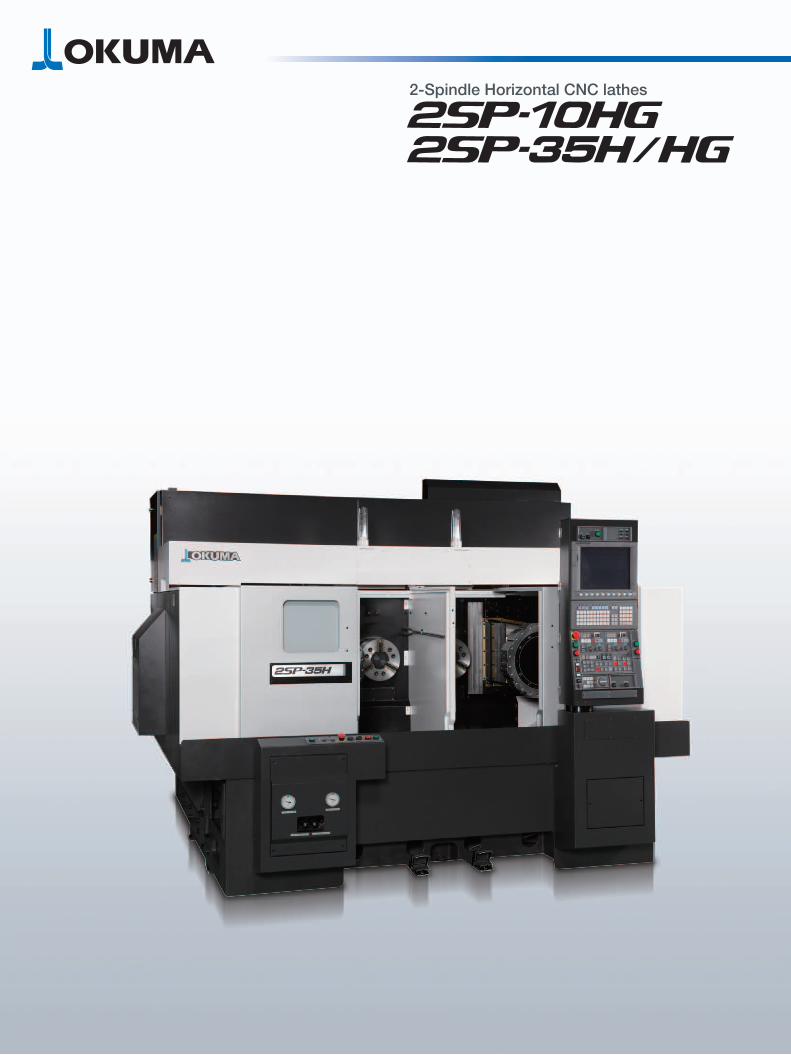
2-Spindle Horizontal CNC lathes
Transcript of 2-Spindle Horizontal CNC lathes - Bulmakmetal...
2-Spindle Horizontal CNC lathes
1 2
2-Spindle Horizontal CNC lathes
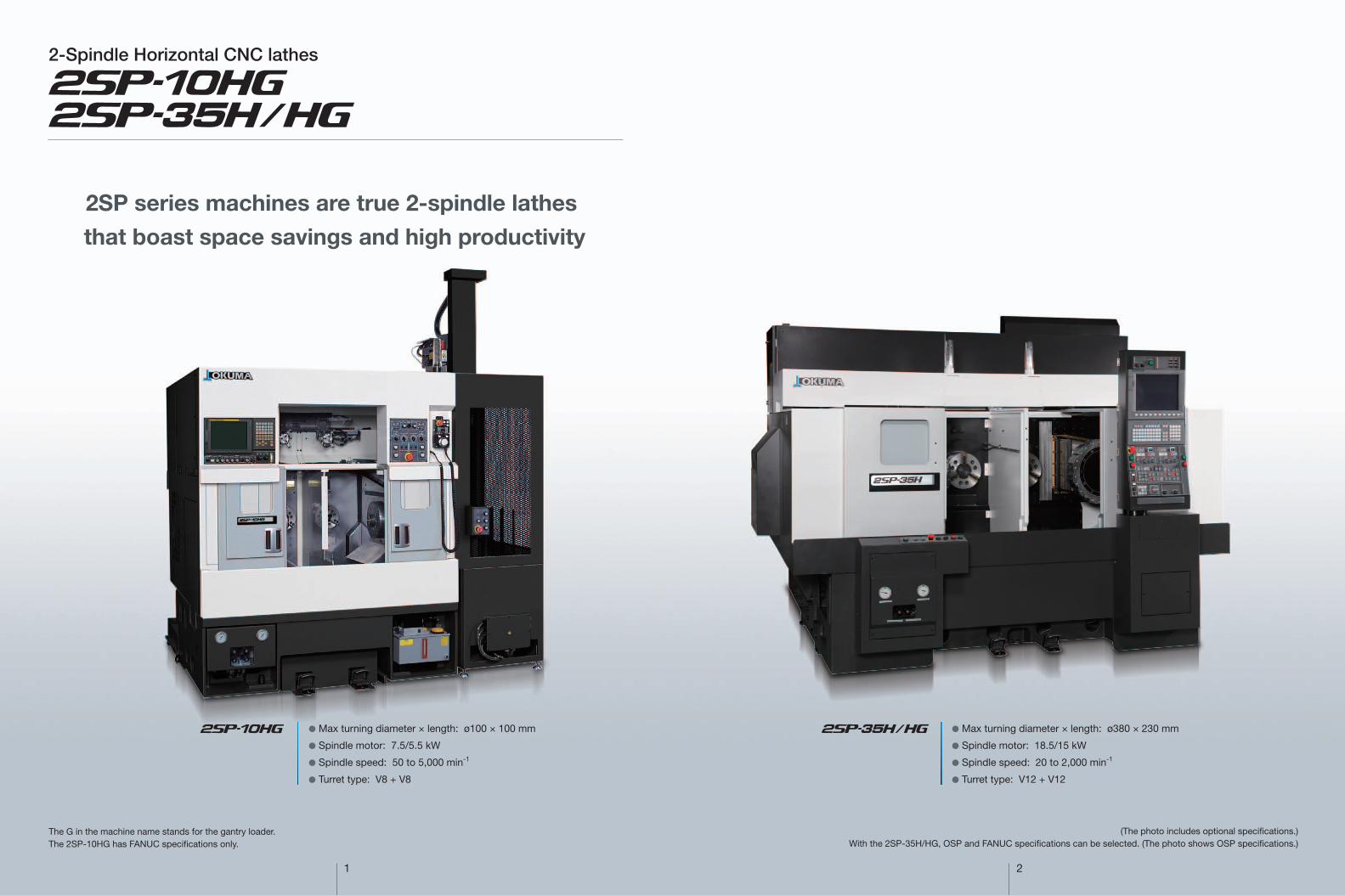
2SP series machines are true 2-spindle lathes
that boast space savings and high productivity
(The photo includes optional speci cations.)With the 2SP-35H/HG, OSP and FANUC speci cations can be selected. (The photo shows OSP speci cations.)
The G in the machine name stands for the gantry loader. The 2SP-10HG has FANUC specifications only.
● Max turning diameter × length: ø100 × 100 mm
● Spindle motor: 7.5/5.5 kW
● Spindle speed: 50 to 5,000 min-1
● Turret type: V8 + V8
● Max turning diameter × length: ø380 × 230 mm
● Spindle motor: 18.5/15 kW
● Spindle speed: 20 to 2,000 min-1
● Turret type: V12 + V12
3
■■■
L R
4
Wide array of results to achieve high utilization
High speed and stable cut
Operator home position
● Operator movement is reduced one-third with one 2SP-H compared to simultaneous use of two general-purpose single spindle NC lathes.
Structural design features“straight down chip drop”
● With the bed directly below a ram-type turret, straight down chip drop results in much shorter chip handling time and steady, long runs. And chips will not build up on any surface within the machine.
● Machine thermal deformation is minimized because chips are caught and discharged by a chip conveyor assembly separate from the bed casting.
Available in 3 different discharge directions to fit your shop layout requirements. A simple push of the button helps reduce
operator fatigue.
This easy-to-use manual Touch Setter really reduces setup times. Making a tool contact the sensor automatically stores an offset in the control system—quickly and accurately.
■ Chip conveyors (Optional) ■ Auto front door open/close (Optional)
■ Touch Setter (Optional) (2SP-35HG)
Wide array of variations significantly shorten setup time
● 2SP–H series lathes
● Two machines
Item
Max Spindle Speed
RapidTraverse(X/Z)
Turret lndexingTime
Unit
min-1
m/min
sec
2SP-10HG
50 to 5,000
24/24
0.2
2SP-35H/-35HG
20 to 2,000
24/30
0.3
Rear discharge (Opt)
Right discharge(Opt)2SP-35H/HG
Left discharge(Opti)2SP-35H/HG
Operation panel
Spindle
2SP-10HG2SP-35H/HG
Boring/drilling and slot machining can be done radially and axially in the workpiece with milling tool attached (multitasking specs).Higher production efficiency achieved with process-intensive machining.
● Example of drill end mill unit
■ Multitasking turret specifications ■ Multitasking turret (Optional)
Item Unit
min−1
mm
mm
mm
mm
kW
deg
deg
deg
2SP-10HG
V10
10
160 to 6,000
ø13
ø12
ø12
M8
1.6
±0.01
3 (X, Z, C)
0.001
0.001
2SP-35H2SP-35HG
V12
6
80 to 5,000
ø20
ø20
ø20
M14
3.5
±0.03
Milling tool spindle
Turret type
No. of controlled axes
No. of milling tools
Spindle speeds
Max milling tool size
Motor
C-axis
Min input
Least command increment
Indexing accuracy
Max tool size
Drill
Endmill
Tap
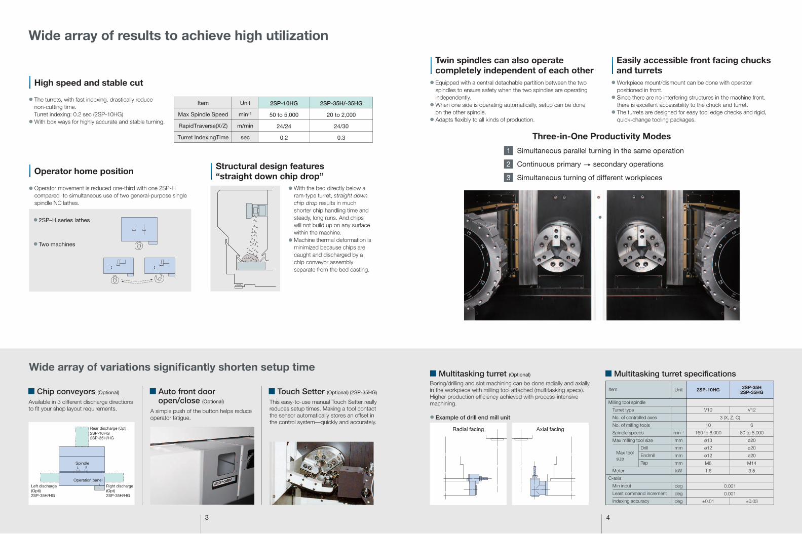
● Equipped with a central detachable partition between the two spindles to ensure safety when the two spindles are operating independently.
● When one side is operating automatically, setup can be done on the other spindle.
● Adapts flexibly to all kinds of production.
● Workpiece mount/dismount can be done with operator positioned in front.
● Since there are no interfering structures in the machine front, there is excellent accessibility to the chuck and turret.
● The turrets are designed for easy tool edge checks and rigid, quick-change tooling packages.
Simultaneous parallel turning in the same operation
Continuous primary secondary operations
Simultaneous turning of different workpieces
1
2
3
Radial facing Axial facing
● The turrets, with fast indexing, drastically reduce non-cutting time.
Turret indexing: 0.2 sec (2SP-10HG)● With box ways for highly accurate and stable turning.
Twin spindles can also operate completely independent of each other
Easily accessible front facing chucks and turrets
Three-in-One Productivity Modes

5
FILE SELECT
[ALARM ][TELCOM][ DATA][ NAME ][POS. ]
ACTIVE FILE : 4 FILE-NO.:WORK-3
FILE-NO. NAME WORK-1 777 WORK-2 893ACTIVE WORK-3 4649 WORK-4 5963 WORK-5 4989
6
R R �ow L R �ow
The photo includes optional specications for this machine.
NC gantry loaders for laborsaving automationWide array of variations to handle all types of production
Gantry loaders—for more productivity and flexibility (Optional)
● Conversational data input for loader movements—a safe, simple, and quick way to set up.
● AC servo drives for all 3 axes enable multiple workpiece and setup changes—quick and easy.
● If trouble occurs, recover methods are displayed on the screen to help the operator respond—quickly.
● A selection of loader movement patterns are available to match various production requirements. This flexibllity helps you make the production line changes that are needed—when you need them.
HG-10A (for 2SP-10HG)
Workpiece
Loader gripper
Traveling speed
Standard loader time (including machine chuck time)*
Min cycle time (16-P stacker, R R �ow)
OD
Length
Weight (one hand)
Loader jaw
Jaw stroke
Horizontal (A axis)
Vertical (B axis)
Front/back (C axis)
Unit
mm (in.)
mm (in.)
kg (lb)
mm (in.)
m/min (fpm)
m/min (fpm)
m/min (fpm)
sec
sec
ø100 (3.94)
75 (2.95)
1.5 (3.3)
3-jaw, with pusher
ø12 (0.47)
150 (492)
120 (394)
40 (131)
7
24
HG-35A (for 2SP-35HG)ø280 (11.02)
160 (6.30)
15 (33)
3-jaw, with pusher
ø40 (1.57)
120 (394)
100 (328)
40 (131)
12
45
■ HG loader specifications
HG-10A (2SP-10HG)
Max workpiece diameter
Max load capacity (1 pallet)
Stacking height
No. of pallets
ø100 (3.94)
30 (66)
460 (18.11)
16
HG-35A (2SP-35HG)
ø280 (11.02)
70 (154)
500 (19.69)
16
■ 16-station worktable specificationsUnit
mm (in.)
kg (lb)
mm (in.)
■ Wide range of loader layouts
* Loader time becomes longer in some cases based on workpiece/chuck specifications.
Loader
Part turn device
Conveyor
Chip conveyor
Gauge
Worktable
Loader with 2 carriers
In-Line Layout
Parallel Layout
■ Automation applications
Gauge Worktable Chuck air blower(blast)
Loader hand Through spindle coolant
Part turn device Palletizing system Chucking miss (air) Workpiece pusher Data files
ODIDWidthRunout
16 stations
Air
Air cylinder
Coolant
(5, 10, 15 workpiece types possible)
Item
Item
7 8
■ Specifications
2SP-35H/HG
450 (17.72)
ø380* [ø280] (ø14.96 [ø11.02])
230 (9.06)
1,205 (47.44)
220 (8.66)
230 (9.06)
JIS A2-8
ø120 (ø4.72)
ø82 (ø3.23)
20 to 2,000
V12 + V12
12 + 12
25 (1)
ø40, ø50 (ø1-1/2, ø2)
30 (1,181)
0.0001 to 300.0 (0.0000040 to 11.81)
18.5/15 × 2 (25/20 × 2)
0.885-4P (AC 1.2-4P × 2)
OSP: 67 (54), FANUC: 66 (53)
3,200 × 2,835 (125.98 × 111.61)
2,260 [4,052] (88.98 [159.53])
9,500 [11,000] (20,900 [24,200])
320 (85)
OSP-P300L / FANUC 31i-B
2SP-10HG
310 (12.20)
ø100 (ø3.94)
100 (3.94)
1,055 (41.54)
150 (5.91)
175 (6.89)
ø140 across �ats
ø80 (ø3.15)
ø52 (ø2.05)
50 to 5,000
V8 + V8 (L turrets)
V10 + V10 (M turrets)
8 + 8
20 (3/4)
ø32 (ø1-1/4)
24 (945)
0.0001 to 120.0 (0.0000040 to 4.72)
7.5/5.5 × 2 (10/7.5 × 2)
0.4-4P × 2 (AC 0.5-4P × 2)
28 (22)
1,650 × 1,857 (64.96 × 73.11)
2,816.7 (110.89)
4,900 (10,780)
200 (53)
FANUC 31i-B
Unit
mm (in.)
mm (in.)
mm (in.)
mm (in.)
mm (in.)
mm (in.)
mm (in.)
mm (in.)
min-1
tools
mm (in.)
mm (in.)
m/min (ipm)
m/min (ipm)
mm/rev (ipr)
kW (hp)
kW (hp)
kW (hp)
kW (hp)
kVA (kW)
mm (in.)
mm (in.)
kg (lb)
L (gal)
L (gal)
L (gal)
Distance between spindle centerlines
Max cutting diameter
Max cutting length
Spindle center height form �oor
X axis
Z axis
Spindle nose
Spindle front bearing dia
Spindle bore dia
Spindle speed ranges
Spindle speed
Turret type
No. of tools
OD tool shank size
ID tool shank diameter
Rapid traverse (X axis)
Rapid traverse (Z axis)
Cutting feederate
Spindle (30 min/cont)
Hydraulic pump
Lubricant pump
Coolant pump
Total power requirement
Floor space (W × L, mach only)
Machine height (w/loader)
Machine weight (w/loader)
Coolant tank
Hydraulic unit tank
Lubricating oil tank
Capacity
Travels
Spindles
Turrets
Feedrates
Motors
Machine Size
CNC
Item Model
* ø310 (12.2) when Touch Setter mounted[ ] With loader
Stepless
24 (945)
1.5 × 4P (2 × 4P)
0.02-4P (0.03-4P)
30 × 2 (8 × 2)
6 (1.6)
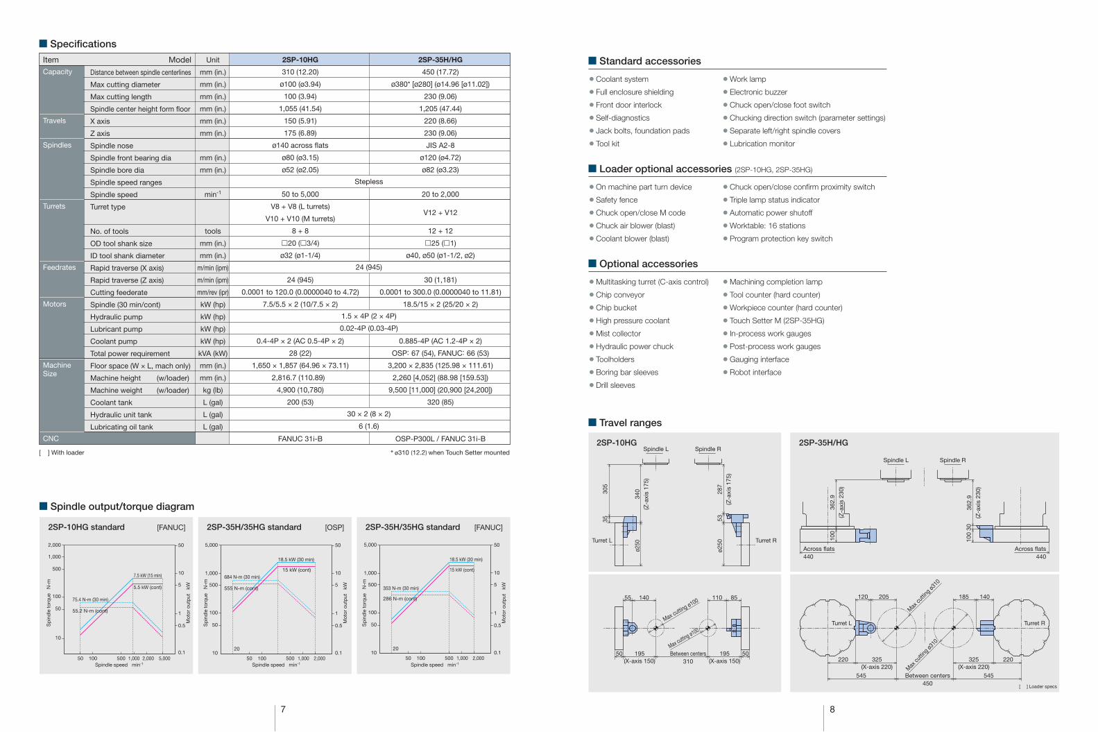
2SP-10HG standard
■ Spindle output/torque diagram
[FANUC] 2SP-35H/35HG standard [OSP] 2SP-35H/35HG standard [FANUC]
75.4 N-m (30 min)
55.2 N-m (cont)
7.5 kW (15 min)
5.5 kW (cont)
18.5 kW (30 min)
15 kW (cont)684 N-m (30 min)
555 N-m (cont)
18.5 kW (30 min)
15 kW (cont)
353 N-m (30 min)
286 N-m (cont)
2SP-10HG 2SP-35H/HG
Turret R
ø250
ø250
3530
5
287
(Z-a
xis
175)
340
(Z-a
xis
175)
Spindle L Spindle R
Across �ats 440
100
362.
9
(Z-a
xis
230)
Across �ats440
100
362.
9
(Z-a
xis
230)
30
■ Standard accessories
● Coolant system
● Full enclosure shielding
● Front door interlock
● Self-diagnostics
● Jack bolts, foundation pads
● Tool kit
● Work lamp
● Electronic buzzer
● Chuck open/close foot switch
● Chucking direction switch (parameter settings)
● Separate left/right spindle covers
● Lubrication monitor
■ Loader optional accessories (2SP-10HG, 2SP-35HG)
● On machine part turn device
● Safety fence
● Chuck open/close M code
● Chuck air blower (blast)
● Coolant blower (blast)
● Chuck open/close confirm proximity switch
● Triple lamp status indicator
● Automatic power shutoff
● Worktable: 16 stations
● Program protection key switch
■ Optional accessories
■ Travel ranges
● Multitasking turret (C-axis control)
● Chip conveyor
● Chip bucket
● High pressure coolant
● Mist collector
● Hydraulic power chuck
● Toolholders
● Boring bar sleeves
● Drill sleeves
● Machining completion lamp
● Tool counter (hard counter)
● Workpiece counter (hard counter)
● Touch Setter M (2SP-35HG)
● In-process work gauges
● Post-process work gauges
● Gauging interface
● Robot interface
53
50 50Between centers310
195(X-axis 150)
55 85140 110
195(X-axis 150)
Max cutting ø100
Max cutting ø100Turret L Turret R
220 220325(X-axis 220)
325(X-axis 220)
120 185 140205
545 Between centers450
545Max
cuttin
g ø31
0
Max cu
tting ø
310
500 1,000 2,000 5,00050 100
500
1,000
2,000
50
10
100
10
5
50
0.5
1
0.1500 1,000 2,00050
20
100
500
1,000
5,000
50
10
100
10
5
50
0.5
1
0.1500 1,000 2,00050
20
100
500
1,000
5,000
50
10
100
10
5
50
0.5
1
0.1
Sp
ind
le t
orq
ue
N-m
Mot
or o
utp
ut
kW
Spindle speed min-1
Sp
ind
le t
orq
ue
N-m
Mot
or o
utp
ut
kW
Spindle speed min-1
Sp
ind
le t
orq
ue
N-m
Mot
or o
utp
ut
kW
Spindle speed min-1
Turret L
Spindle L Spindle R
[ ] Loader specs

9 10
2SP-10HGDimensional Drawing / Installation Drawing
Chip conveyor(Opt)
Right spindle coolant pump
Left spindlecoolant pump
2,670 (105.12)
1,650 (64.96) 46046050 50
630(24.80)
390(15.35)
630(24.80)
1,63
52.
3(0
.09)
816.
7
1,82
5 (7
1.85
)62
9 (2
4.76
)
2,45
4 (9
6.61
)
684
(26.
93)
600
(23.
62)
1,17
0 (4
6.06
)
2,670 (105.12)
2,631 (103.58)
460
490.5 490.5
670
50
670
1,650
460310
150150 4545
270 314
2,01
7.3
(79.
42)
1,05
5 sp
indl
e he
ight
Sub-operation panel
Pulse handleRight turret
Lube unit
16-P stacker
(Opt)
(Opt)
(2,8
16.7
) [11
0.89
]
Status indicator
Right spindleLeft spindleOperation monitor
Left turret
Chuckmanual blower
50 16-P stacker(Opt)
Loader(Opt)
1,27
7 (5
0.28
)73
8 (2
9.06
)
(Chip conveyor removal)
1,05
554
5Tr
avel
195Travel
1,60
0 (6
2.99
)
2,01
5 (7
9.33
)
1,900 (74.80)2,434 (95.83)20
600 (23.62)940 (37.01)195(7.68)
681.71,752.3 (68.99)
1,095 710
750
360.2 194.8
Chip conveyor(Opt)
Hydraulic unit(Left/right 1 ea)
(803
.2)
■ Chip conveyor types and applications
Various Chip Conveyors
Name Hinge Scraper Magnet scraper
● For steel and general use ● For cast iron ● Easy to maintain ● Blade scraper ● Magnet scraper for sludge processing
● For cast iron ● Effective for sludge handling
Magnet
2SP-35HDimensional Drawing / Installation Drawing
Auxiliary control panel Operation panel
(Opt)525 325
850 (33.46)410(16.14)
292.3 1,347.7 (53.06)
Hydraulic chuck pressure regulator
Rightheadstock
Leftheadstock
RightturretLeft turret
(Opt)
Chipconveyor L
(Opt)
Chipconveyor R
2,26
0 (1
49.6
1)
1,05
5 (4
1.54
)1,
205
(47.
44)
919.
2
919.
2
1,4501,450
2,900 (114.17) 150150
3,200 (125.98)
450(17.72)
1,225 (48.23)1,225 (48.23) 819.7 (32.27)819.7 (32.27)
Hydraulic unit Coolant tank
Status indicator
Control cabinet
Lube unit
(Opt)
Chip conveyor rear output
(Opt)Chip bucket
175
810
(31.
89)
1,01
5 (3
9.96
)
1,20
5 (4
7.44
)43
016
5
650
(25.
59)
965
(37.
99)
645
(25.
39)
700 907
207
2,26
0 (8
8.98
)
1,710 810
2,520 (99.21)245
2,765 (108.86)
2,100 (82.68)425
2SP-35HGDimensional Drawing / Installation Drawing
1,000
1,000
2,900
5,350 (210.63)
225
265265
1,000 225
200
427.
7
2,450 225 2251,225 (48.23)2,900 (114.17)
1,2251,225
780.
942
565
8
179.
530
02,
110
(83.
07)
1,08
3 (4
2.64
)3,
800
(149
.61)
1,76
0.6
(69.
31)
2,03
9.4
(80.
29)
3,80
0 (1
49.6
1)80
4(3
1.65
)
355.
6
785.
51,
210.
5
(36.
4)
[Current L/R stackers: 5850 (230.31)]
1,000 225 2251,225 (48.23)
Main operationpanel
Airsupply port
Main power supply
1,000
2,900 (114.17)
225 2251,000 1,450 1,450
1,225 (48.23)1,225 (48.23)5,350 (210.63)
465 4651.6 1.6
4501,825 1,825
160.7 160.75,354.6 (210.81)5,033.2 (198.16)
5,0304,100
2,40
0 (9
4.49
)1,
289
(50.
75)
839
450
295
700
1,20
517
52,
200
(86.
61)
2,37
5 (9
3.50
)
(262)(262)
Lube unit (Chip conveyor discharge ht)
340
1,01
51,
045
700.
735
5.6
1,20
5 (4
7.44
)1,
056.
3 (4
1.59
)1,
790.
9 (7
0.51
)4,
052.
2 (1
59.5
4)
3,800 (149.61)176.3 2,835 (111.61)
315 2,5201,710 810
1,263 (49.72) 729(28.70)
600(23.62)
1,080 (42.52)1,217
1373,809 (149.96)
614.5
10150
650
1,60
0.5
(63.
01)
799.
5(3
1.48
)1,61
0
900
256
Coolant tank
Spindle nose
Base edge
Chip conveyor
Hydraulic unit(Left/right 1 ea)
Application
Shape
Status indicator16-P stacker
(L)
16-P stacker(R)
Safety fence L(16-P stacker)
Safety fence R(16-P stacker)
981.6 (38.65)

This product is subject to the Japanese government Foreign Exchange and Foreign Trade Control Act with regard to security controlled items; whereby Okuma Corporation should be noti�ed prior to its shipment to another country.
, OGUCHI-CHO, NIWA-GUN, AICHI 480-0193, JAPAN • TEL (0587) 95-7825 • FAX (0587) 95-6074
2-Sp
indle H
orizo
ntal CN
C lathes
■ Tooling Systems
OD tool shank 25 × 25
ø40
ø40 (ø1-1/2)
OD tool shank 20 × 20
ø32
ø32 (ø1-1/4)
DS MT No.1-H32DS MT No.2-H32
BS 8-H32BS 10-H32BS 12-H32BS 16-H32BS 20-H32BS 25-H32
Drill sleeves Boring bar sleeves
2SP-10HG 2SP-35H/HG
DS MT No.1-H40DS MT No.2-H40DS MT No.3-H40DS MT No.4-H40
BS 8-H40BS 10-H40BS 12-H40BS 16-H40BS 20-H40BS 25-H40BS 32-H40
Drill sleeves Boring bar sleeves
OD- 20
OD- 20
● The sp
eci�cations, illustrations, and d
escriptions in this b
rochure vary in different m
arkets and
are subject to change w
ithout notice.P
ub N
o. 2SP
-H-E
-(10a)-200 (Feb 2015) P
rinted in Jap
an
When using O
kuma p
roducts, alw
ays read the safety p
recautionsm
entioned in the instruction m
anual and attached
to the prod
uct.
Ⅰ
Drills Drill sleeve
Boring bars Boring bar sleeve
Boring bars, ø32 (ø1-1/4)
ID-H32
ID-H32(offset)
V8 turretDrills
Boring bars
Boring bars, ø40 (ø1-1/2)
Drill sleeve
Boring bar sleeve
V12 turret
ID-H40
ID-H40(offset)
OD- 25
OD- 25
Ⅰ
(3/4 × 3/4) (1 × 1)