2-D LOCATION POINTING SYSTEM FOR …eprints.utar.edu.my/515/1/3E-2012-0804268-1.pdf2-D LOCATION...
106
2-D LOCATION POINTING SYSTEM FOR INDIVIDUAL COMPONENT ON DEVICE UNDER TEST USING LABVIEW (HARDWARE AND IMAGE PROCESSING) CH’NG KHAI CHIAH A project report submitted in partial fulfilment of the requirements for the award of Bachelor of Engineering (Hons.) Electrical and Electronic Engineering Faculty of Engineering and Science Universiti Tunku Abdul Rahman April 2012
Transcript of 2-D LOCATION POINTING SYSTEM FOR …eprints.utar.edu.my/515/1/3E-2012-0804268-1.pdf2-D LOCATION...
2-D LOCATION POINTING SYSTEM FOR INDIVIDUAL COMPONENT
ON DEVICE UNDER TEST USING LABVIEW
(HARDWARE AND IMAGE PROCESSING)
CH’NG KHAI CHIAH
A project report submitted in partial fulfilment of the
requirements for the award of Bachelor of Engineering
(Hons.) Electrical and Electronic Engineering
Faculty of Engineering and Science
Universiti Tunku Abdul Rahman
April 2012

ii
DECLARATION
I hereby declare that this project report is based on my original work except for
citations and quotations which have been duly acknowledged. I also declare that it
has not been previously and concurrently submitted for any other degree or award at
UTAR or other institutions.
Signature : ________________________
Name : CH’NG KHAI CHIAH
ID No. : 08UEB04268
Date : ________________________

iii
APPROVAL FOR SUBMISSION
I certify that this project report entitled “2-D LOCATION POINTING SYSTEM
FOR INDIVIDUAL COMPONENT ON DEVICE UNDER TEST USING
LABVIEW (HARDWARE AND IMAGE PROCESSING)” was prepared by
CH’NG KHAI CHIAH has met the required standard for submission in partial
fulfilment of the requirements for the award of Bachelor of Engineering (Hons.)
Electrical and Electronic Engineering at Universiti Tunku Abdul Rahman.
Approved by,
Signature : _________________________
Supervisor : Mr. See Yuen Chark
Date : _________________________

iv
The copyright of this report belongs to the author under the terms of the
copyright Act 1987 as qualified by Intellectual Property Policy of University Tunku
Abdul Rahman. Due acknowledgement shall always be made of the use of any
material contained in, or derived from, this report.
© 2012, Ch’ng Khai Chiah. All right reserved.

v
Specially dedicated to
my beloved family,
supervisor Mr. See Yuen Chark,
and partners Ms. Chung Ka Siew, Mr.Cheng Xuan Teng

vi
ACKNOWLEDGEMENTS
I would like to thank everyone who had contributed to the successful completion of
this project. I would like to express my gratitude to my research supervisor, Mr.See
Yuen Chark for his invaluable advice, guidance and his enormous patience
throughout the development of the research.
In addition, I would also like to express my gratitude to my loving parent and
friends who had helped and given me encouragement throughout the research of the
final year project. They gave me untiring support along the progress, and it has been
of great value to me in order to complete the final year project. I am grateful to their
help, courage and support.
Next, I wish to express my sincere appreciation to my partners, Ms. Chung
Ka Siew and Mr Cheng Xuan Teng who gave me the opportunity to work with them
and learning together in the development of research. Their effort, understanding and
personal guidance have provided key support to me throughout the development of
final year project.

vii
2-D LOCATION POINTING SYSTEM FOR INDIVIDUAL COMPONENT
ON DEVICE UNDER TEST USING LABVIEW
(HARDWARE AND IMAGE PROCESSING)
ABSTRACT
Nowadays, electronic components are getting complex in design and smaller in size.
In order to maintain efficiency while engineers perform validation, probing and
component searching, a high performance system that can assist them in completing
the tasks smoothly is needed. This issue has motivated the researchers to design a
system that is capable of enhancing the users' experience in component searching and
probing. Users can easily search a component from a high density circuit board as
long as the schematic diagram of the particular board is available. This application
has two major parts: hardware implementation and image processing. A personal
computer acts as a host for the whole system which integrates image capturing
device, NI sbRIO-9632XT and EAGLE to work together as a component locating
system. User can perform probing with the installed probe holder. The programming
implementation of the system uses LabVIEW 2011, licensed by National Instruments.
LabVIEW FPGA Module is used to configure onboard NI sbRIO-9632XT device in
order to interface with the hardware including motors, LED, LCD, switches and etc,
from the 2-D Location Pointing System. The image capturing device, which is C170
Logitech Webcam of the system is processed by LabVIEW Vision Acquisition
Software.
viii
TABLE OF CONTENTS
DECLARATION ii
APPROVAL FOR SUBMISSION iii
ACKNOWLEDGEMENTS vi
ABSTRACT vii
TABLE OF CONTENTS viii
LIST OF TABLES xi
LIST OF FIGURES xii
LIST OF SYMBOLS / ABBREVIATIONS xv
LIST OF APPENDICES xvi
CHAPTER
1 INTRODUCTION 1
1.1 Background 1
1.2 Motivation 2
1.3 Project Scope 4
1.4 Aims and Objectives 5
2 LITERATURE REVIEW 6
2.1 National Instruments LabVIEW 6
2.1.1 LabVIEW 2011 7
2.2 Electrical Motors 9
2.2.1 Types of Motors 9
2.3 Laser Pointer 14
2.3.1 Introductions 14

ix
2.3.2 Types of Laser Pointer 15
2.3.3 Comments 16
2.4 Image Processing 17
2.4.1 Edge Detection 17
2.4.2 Pattern Matching 18
2.4.3 Other Searching Techniques 19
3 METHODOLOGY 22
3.1 Overview 22
3.2 Mechanical Structure 26
3.3 NI sbRIO-9632XT 27
3.4 Electrical Motors 28
3.5 Image Processing 29
3.5.1 Template Locate 31
3.5.2 Image Relocation 32
3.6 Liquid Crystal Displays 33
4 IMPLEMENTATION OF SYSTEM AND OUTCOMES 34
4.1 Overall Implementation 34
4.2 Hardware Design Architecture 37
4.2.1 Stepper Motors 38
4.2.2 LCD Displays 44
4.2.3 Hardware Controls and Indications 45
4.2.4 Laser Pointer 47
4.2.5 Outcome 48
4.3 Image Processing 49
4.3.1 Template Processing 51
4.3.2 Pattern Matching Implementation 53
4.4 Program Flow Implementation 57
4.4.1 Implementation 57
4.4.2 Outcome 58
5 CONCLUSION AND FUTURE IMPLEMENTATION 62

x
REFERENCES 64
APPENDICES 66

xi
LIST OF TABLES
TABLE TITLE PAGE
1.1 Main Package of SMD Resistor Sizes 3
2.1 New Features in NI LabVIEW 2011 (National
Instruments, 2012) 7
2.2 Types of Laser Pointers (Jim Samposzi, 2009) 15
2.3 Classifications of Laser Pointers (World Health
Organization, 1998) 16
2.4 Advantages and Disadvantages of Edge Detectors
(Raman Maini & Dr. Himanshu Aggarwal) 17
2.5 Different Techniques of Pattern Matching 19
3.1 List of I/O Table for System 28
3.2 Neocene 2T357247 29
4.1 List of Devices 35
4.2 Overall Dimension of the System 36
4.3 Devices Input/Output Connections on NI sbRIO-
9632XT 37
4.4 Full Step Drive of Stepper Motors 40
4.5 Experiment on X-axis Stepper Motor 41
4.6 Experiment on Y-axis Stepper Motor 41
4.7 Display of LCD and Descriptions 44
4.8 Characteristics of Laser Pointer 47
4.9 Description of Program States 57
xii
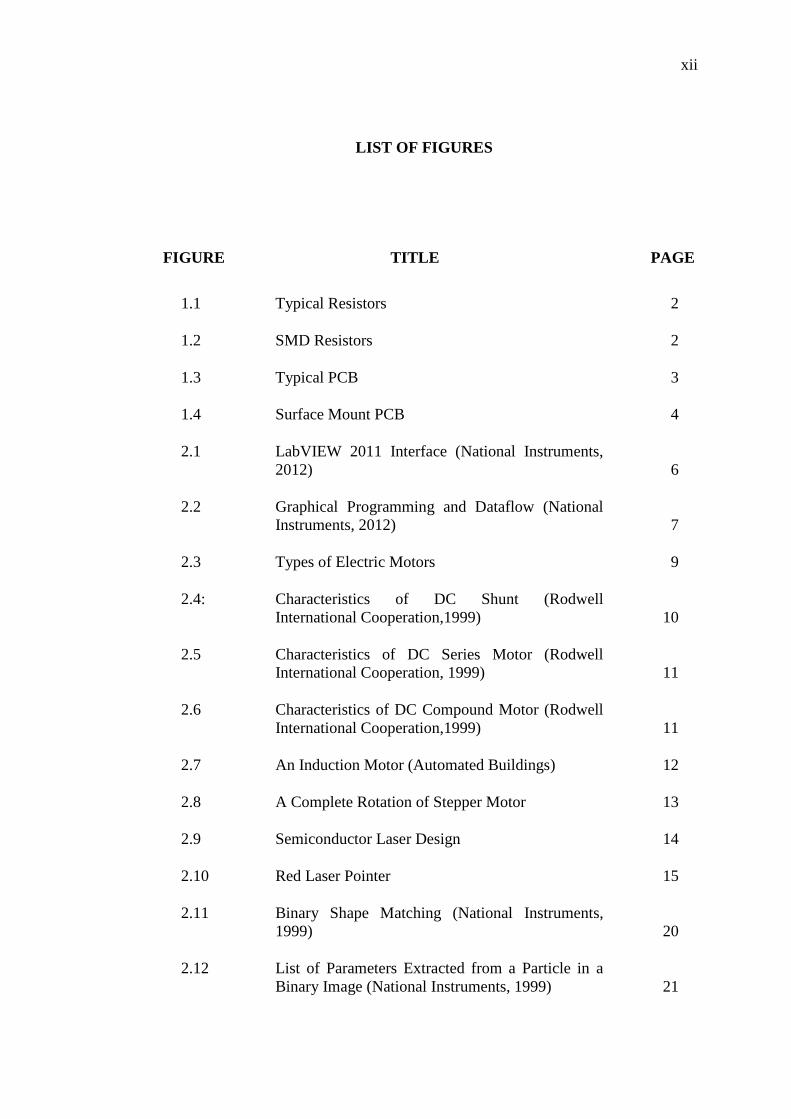
LIST OF FIGURES
FIGURE TITLE PAGE
1.1 Typical Resistors 2
1.2 SMD Resistors 2
1.3 Typical PCB 3
1.4 Surface Mount PCB 4
2.1 LabVIEW 2011 Interface (National Instruments,
2012) 6
2.2 Graphical Programming and Dataflow (National
Instruments, 2012) 7
2.3 Types of Electric Motors 9
2.4: Characteristics of DC Shunt (Rodwell
International Cooperation,1999) 10
2.5 Characteristics of DC Series Motor (Rodwell
International Cooperation, 1999) 11
2.6 Characteristics of DC Compound Motor (Rodwell
International Cooperation,1999) 11
2.7 An Induction Motor (Automated Buildings) 12
2.8 A Complete Rotation of Stepper Motor 13
2.9 Semiconductor Laser Design 14
2.10 Red Laser Pointer 15
2.11 Binary Shape Matching (National Instruments,
1999) 20
2.12 List of Parameters Extracted from a Particle in a
Binary Image (National Instruments, 1999) 21
xiii
3.1 Overall Block Diagram for 2-D Location Pointing
System for Individual Component on Device
Under Test 23
3.2 Windows User Interface 24
3.3 Flowchart of System Programming Concept 25
3.4 Draft Mechanical Structure Design 26
3.5 NI sbRIO-9632XT Front View 27
3.6 NEOCENE Stepper Motor 28
3.7 Procedure of Image Processing 30
3.8 IMAQ Clamp Vertical Max VI (LabVIEW 2011) 31
3.9 Example of Pattern Matching 32
3.10 2 x 16 LCD 33
4.1 Side View of the System 34
4.2 Plan View of the System 35
4.3 NES-100-24 Single Output Switching Power
Supply 36
4.4 X-axis Stepper Motor 39
4.5 Y-axis Stepper Motor 39
4.6 Stepper Motors and ULN2803 40
4.7 Lever Switch Circuit 42
4.8 “motor run.vi” ModuleThe operation of stepper
motors can be viewed in Figure 4.9: 42
4.9 Flowchart of Stepper Motors 43
4.10 LCD Display during Implementation 44
4.11 "LCD module.vi" Module 45
4.12 Physical Switches of the System 45
4.13 LED Indicators of the System 46

xiv
4.14 Circuit Design for LED Lighting System 46
4.15 Laser Pointer Embedded in Polyethylene 47
4.16 Outcome of Hardware Circuits 48
4.17 The Mechanism of Camera Holder 49
4.18 Working Principle of Image Processing 50
4.19 Good Quality Template 51
4.20 Bad Quality Template 52
4.21 Image Clamping with Contrast=10 52
4.22 Image Clamping with Contrast=50 53
4.23 Image Clamping with Contrast=100 53
4.24 Pattern Matching with Good Quality Template 54
4.25 Pattern Matching with Bad Quality Template 54
4.26 Image Captured at Indoor during Daylight 55
4.27 Image Captured with Lighting System Enabled 55
4.28 Image Captured with Interrupt of Extra Object 56
4.29 Image Captured with Objects Not Parallel with
Platform 56
4.30 Finite State Machine of the System 57
4.31 GUI on “Start” 58
4.32 GUI on “Set Path for EAGLE” 58
4.33 GUI on “Select Schematic” 59
4.34 GUI on “Load Schematic to Front Page” 59
4.35 GUI on “Set as Template?” 60
4.36 GUI on “Send Searched Components’ Record to
Email” 60
4.37 Program Flow of 2-D Location Pointer 61

xv
LIST OF SYMBOLS / ABBREVIATIONS
AC Alternating Current
API Application Programming Interface
DC Direct Current
DRAM Dynamic Random Access Memory
DUT Device Under Test
FPGA Field-Programmable Gate Array
FTP File Transfer Protocol
GUI Graphical User Interface
HTTP Hypertext Transfer Protocol
IMAQ Image Acquisition
LabVIEW Laboratory Virtual Instrumentation Engineering Workbench
LCD Liquid Crystal Display
LED Light-Emitting Diode
NI National Instruments
OS Operating System
PC Personal Computer
PCI Peripheral Component Interconnect
RF Radio Frequency
RIO Reconfigurable Input/Output
sbRIO Single Board Reconfigurable Input/Output
SMTP Simple Mail Transfer Protocol
SSL Secure Socket Layer
TLS Transport Layer Security
USB Universal Serial Bus
VHDL VHSIC Hardware Description Language
VHSIC Very High Speed Integrated Circuit
VI Virtual Instrument

xvi
LIST OF APPENDICES
APPENDIX TITLE PAGE
A LabVIEW Graphical Programming 66
B Schematic of Motors and Lighting Controllers 88
C Schematic of LCD and Switches Circuit Design 89
D Schematic of LED Circuit Design 90

1
CHAPTER 1
1 INTRODUCTION
1.1 Background
Since technological advancement began, electronic gadgets have played an important
role in daily life to fulfil our present needs. Consumer’s requirements on the
technology of electronic devices are getting higher in order to help us act and think
better. As the technology of electronic devices is getting complicated, it is
undoubtedly that the number of components included in design of electronic devices
will exponentially increase with the trend of complexity.
To maintain the reliability and quality of the electronic gadgets, engineers in
test development department play an important role in validating the functionality of
the products. One of the most important tasks is to perform device under test (DUT).
The term DUT is refers to any electronic assembly under test. When the DUT is a
complicated board, the process of probing is undeniably time consuming as the
engineers have to be focused to look for the location of individual component to be
probed on the DUT.
2
1.2 Motivation
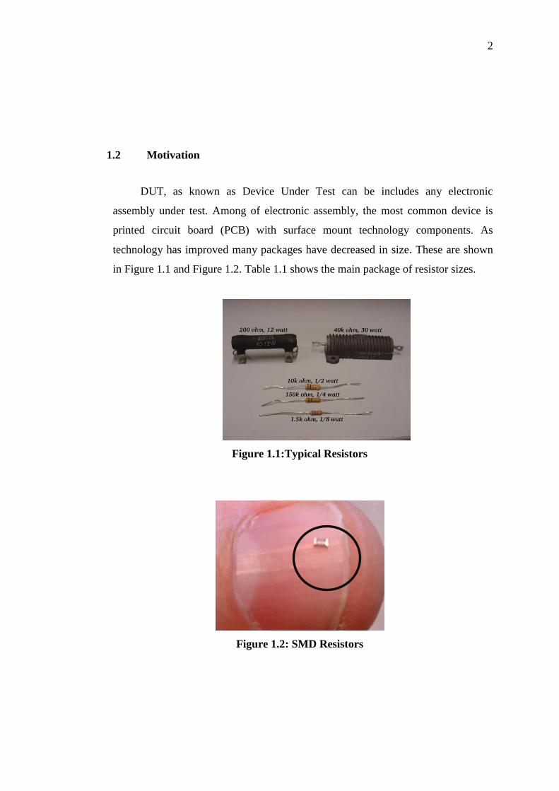
DUT, as known as Device Under Test can be includes any electronic
assembly under test. Among of electronic assembly, the most common device is
printed circuit board (PCB) with surface mount technology components. As
technology has improved many packages have decreased in size. These are shown
in Figure 1.1 and Figure 1.2. Table 1.1 shows the main package of resistor sizes.
Figure 1.1:Typical Resistors
Figure 1.2: SMD Resistors

3
Table 1.1: Main Package of SMD Resistor Sizes
Package Style Size (mm) Size (Inches)
2512 6.30 x 3.10 0.25 x 0.12
2010 5.00 x 2.60 0.20 x 0.10
1812 4.6 x 3.0 0.18 x 0.12
1210 3.20 x 2.60 0.12 x 0.10
1206 3.0 x 1.5 0.12 x 0.06
0805 2.0 x 1..3 0.08 x 0.05
0603 1.5 x 0.08 0.06 x 0.03
0402 1 x 0.5 0.04 x 0.02
0201 0.6 x 0.3 0.02 x 0.01
It is still easy to identify component from printed circuit board if typical
electronic components are used, as in Figure 1.3. Due to introduction of surface
mount technology and the increment of package density, surface mount devices are
relatively tiny compare with typical components when it mounted on the printed
circuit board as in Figure 1.4.
Figure 1.3: Typical PCB

4
Figure 1.4: Surface Mount PCB
It is time consuming when engineers need to identify a particular component
within the printed circuit board as tiny as shown in Figure 1.4 in order to perform
probing, validation or testing. Although engineers will refer to schematic layout and
components’ label to find out the position of particular component, but it is not
efficient without get assistant from the pointing system.
1.3 Project Scope
The Project aims to build a platform which consists of two motors rotate in x and y
axis. Laser pointer is moved in two axes so it can point on the particular component
of the object. The area of pointing is limited by the size of the platform and
movement length of respective motors.
Besides, a lockable multipurpose flexible holder is designed not only to hold
the test probe during the probing process, but also to hold other devices when
necessary, such as soldering lead.
First of all, the project focuses on the structure design of the platform. Size of
workable DUT is limited, depends on the coverage of camera and size of structure.

5
The whole structure is designed in order to be able to hold the motors, camera, laser
pointer, and all the circuitry components.
Next, the project focuses on the programming and software implementation.
Graphical User Interface is designed so that user can communicate with the whole 2-
D location pointing system. A lockable multipurpose flexible holder is designed to
assist user do probing and soldering. In order to provide user convenience while
using holder, the lock can controlled by voice command.
There are few limitations when using the system. Firstly, the system is able to
search component on the front side of DUT only. Secondly, camera is fixed install on
top of the structure, hence the area captured is fixed and limited. Lastly, user need to
placed DUT at fixed location to obtain template before the system run image locating
itself.
1.4 Aims and Objectives
The aim of this project is to speed up the component searching process. There are
two sections in this project, where two main objectives are to be delivered. The first
section is to study and identify the displacement control of the motors while second
section aims to create an image locating function. In interest of this objective, some
tasks are set to be fulfilled as following:
To learn to operate LabVIEW as a programming tool
To study pre-defined functions available in LabVIEW that enable it to
connect to external application
Build up a platform that allow user to do probing component searching on
DUT.
Identify the location of DUT by camera capture process.
Create link between PC and platform with appropriate software.
Create GUI on PC so user can control the platform.

6
CHAPTER 2
2 LITERATURE REVIEW
2.1 National Instruments LabVIEW
LabVIEW, also known as Laboratory Virtual Instrumentation Engineering
Workbench is a system design platform and graphical development environment for
visual programming language from National Instruments. It used to develop
sophisticated measurement, test, and control systems using intuitive graphical icons
and wires that resemble a flowchart (National Instruments, 2012).
Figure 2.1: LabVIEW 2011 Interface (National Instruments, 2012)
LabVIEW is different from most other general-purpose programming
languages. It provides faster programming due to its graphical programming features,
known as G Programming. Users only program with drag-and-drop, graphical
function blocks instead of writing lines of text such as C programming codes. In
other words, G programming is typically easier to quickly understand because they
are largely familiar with visualizing.

7
Figure 2.2: Graphical Programming and Dataflow (National Instruments, 2012)
2.1.1 LabVIEW 2011
LabVIEW 2011 is the latest version of system design software from National
Instruments. It increases development efficiency to interact with almost any
hardware device or deployment target. The following table shows the new features in
NI LabVIEW 2011:
Table 2.1: New Features in NI LabVIEW 2011 (National Instruments, 2012)
New Features Descriptions
Improved Stability -Several changes were made that impact the
time it takes to launch LabVIEW and load VI
hierarchies.
Feedback-Driven Improvements -Improved LabVIEW usability
-Redesigned Block Diagram Objects
-Front Panel Enhancements
-LabVIEW Environment Enhancements.
UI Enhancements -New palette of controls and indicators.
Asynchronous Call by Reference -Improve the execution time of the calling VI
by allowing the subVI run in parallel with the
calling VI

8
Improved Real-Time Deployment -Greatly reduce deployment times.
Edit-Time Improvements to
LabVIEW FPGA
-Node framework is highly optimized to speed
up the loading of larger Vis
-Nodes have been reimplemented to remove
any edit-time performance issues.
-Interface has been rearchitected to provide a
far more responsive editing experience.
-FPGA compilation is optimized to be up to
80% faster.
New Math and Signal Processing
Functions
-Provides new built-in algorithms in
geometry, linear algebra and signal processing
areas.
Application Builder API -Provides application builder Vis to build,
deploy or clean build specifications.
Improved Support -Introducing easier way to report crashes.
-New features have been added to help
visualize which assemblies have been loaded
in LabVIEW memory.
-Give option of visiting the NI website to
download the appropriate software needed to
run their executable.

9
2.2 Electrical Motors
Electrical motors play a role in converting electrical energy into mechanical energy.
Force is generated through the interaction of magnetic fields and current-carrying
conductors. In an electrical motor the moving part is called the rotor and the
stationary part is called the stator.
2.2.1 Types of Motors
Motors can be powered by either direct current or alternating current, Figure
2.3 shows the categorization of electrical motors:
Electric Motors
DC Motors AC Motors Other Motors
Seperately Excited Self Excited
Series Shunt Compound
Synchronous Induction Stepper Motors
Brushless DC Motors
Hysteresis Motors
Reluctance Motors
Universal Motors
Figure 2.3: Types of Electric Motors
10
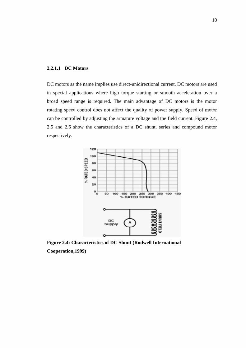
2.2.1.1 DC Motors
DC motors as the name implies use direct-unidirectional current. DC motors are used
in special applications where high torque starting or smooth acceleration over a
broad speed range is required. The main advantage of DC motors is the motor
rotating speed control does not affect the quality of power supply. Speed of motor
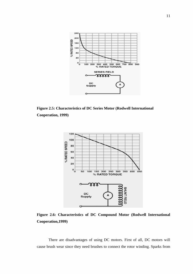
can be controlled by adjusting the armature voltage and the field current. Figure 2.4,
2.5 and 2.6 show the characteristics of a DC shunt, series and compound motor
respectively.
Figure 2.4: Characteristics of DC Shunt (Rodwell International
Cooperation,1999)
11
Figure 2.5: Characteristics of DC Series Motor (Rodwell International
Cooperation, 1999)
Figure 2.6: Characteristics of DC Compound Motor (Rodwell International
Cooperation,1999)
There are disadvantages of using DC motors. First of all, DC motors will
cause brush wear since they need brushes to connect the rotor winding. Sparks from
12
the brushes may cause explosion if the environment contains explosive materials.
Furthermore, RF noise from the brushes may interfere with nearby electronic devices
such as television.
2.2.1.2 AC Motors
AC motors use an alternating current which reverses its direction at regular intervals.
There are two main electrical parts: the stationary part called stator and the rotating
part called rotor. A synchronous motor runs at constant speed fixed by frequency of
the system. It suited for applications that start with a low load since it has low
starting torque and requires direct current for excitation.
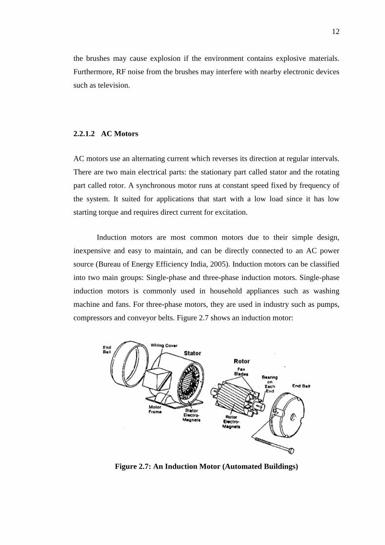
Induction motors are most common motors due to their simple design,
inexpensive and easy to maintain, and can be directly connected to an AC power
source (Bureau of Energy Efficiency India, 2005). Induction motors can be classified
into two main groups: Single-phase and three-phase induction motors. Single-phase
induction motors is commonly used in household appliances such as washing
machine and fans. For three-phase motors, they are used in industry such as pumps,
compressors and conveyor belts. Figure 2.7 shows an induction motor:
Figure 2.7: An Induction Motor (Automated Buildings)
13
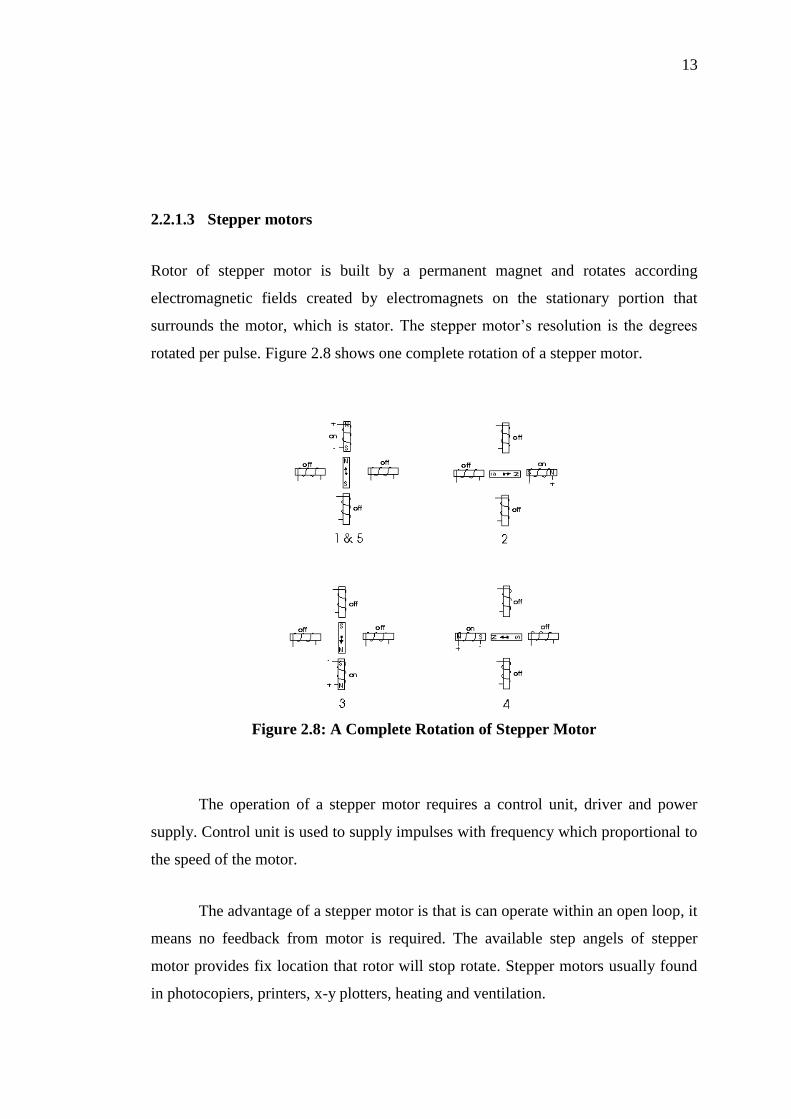
2.2.1.3 Stepper motors
Rotor of stepper motor is built by a permanent magnet and rotates according
electromagnetic fields created by electromagnets on the stationary portion that
surrounds the motor, which is stator. The stepper motor’s resolution is the degrees
rotated per pulse. Figure 2.8 shows one complete rotation of a stepper motor.
Figure 2.8: A Complete Rotation of Stepper Motor
The operation of a stepper motor requires a control unit, driver and power
supply. Control unit is used to supply impulses with frequency which proportional to
the speed of the motor.
The advantage of a stepper motor is that is can operate within an open loop, it
means no feedback from motor is required. The available step angels of stepper
motor provides fix location that rotor will stop rotate. Stepper motors usually found
in photocopiers, printers, x-y plotters, heating and ventilation.
14
2.3 Laser Pointer
2.3.1 Introductions
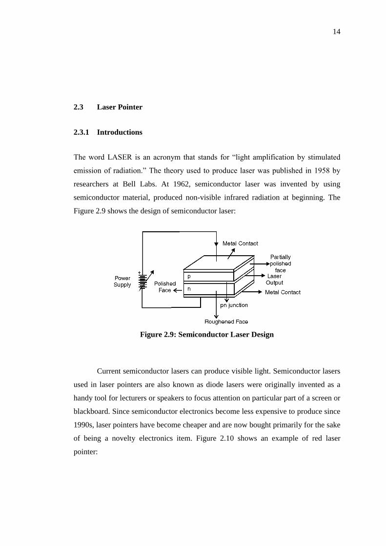
The word LASER is an acronym that stands for “light amplification by stimulated
emission of radiation.” The theory used to produce laser was published in 1958 by
researchers at Bell Labs. At 1962, semiconductor laser was invented by using
semiconductor material, produced non-visible infrared radiation at beginning. The
Figure 2.9 shows the design of semiconductor laser:
Figure 2.9: Semiconductor Laser Design
Current semiconductor lasers can produce visible light. Semiconductor lasers
used in laser pointers are also known as diode lasers were originally invented as a
handy tool for lecturers or speakers to focus attention on particular part of a screen or
blackboard. Since semiconductor electronics become less expensive to produce since
1990s, laser pointers have become cheaper and are now bought primarily for the sake
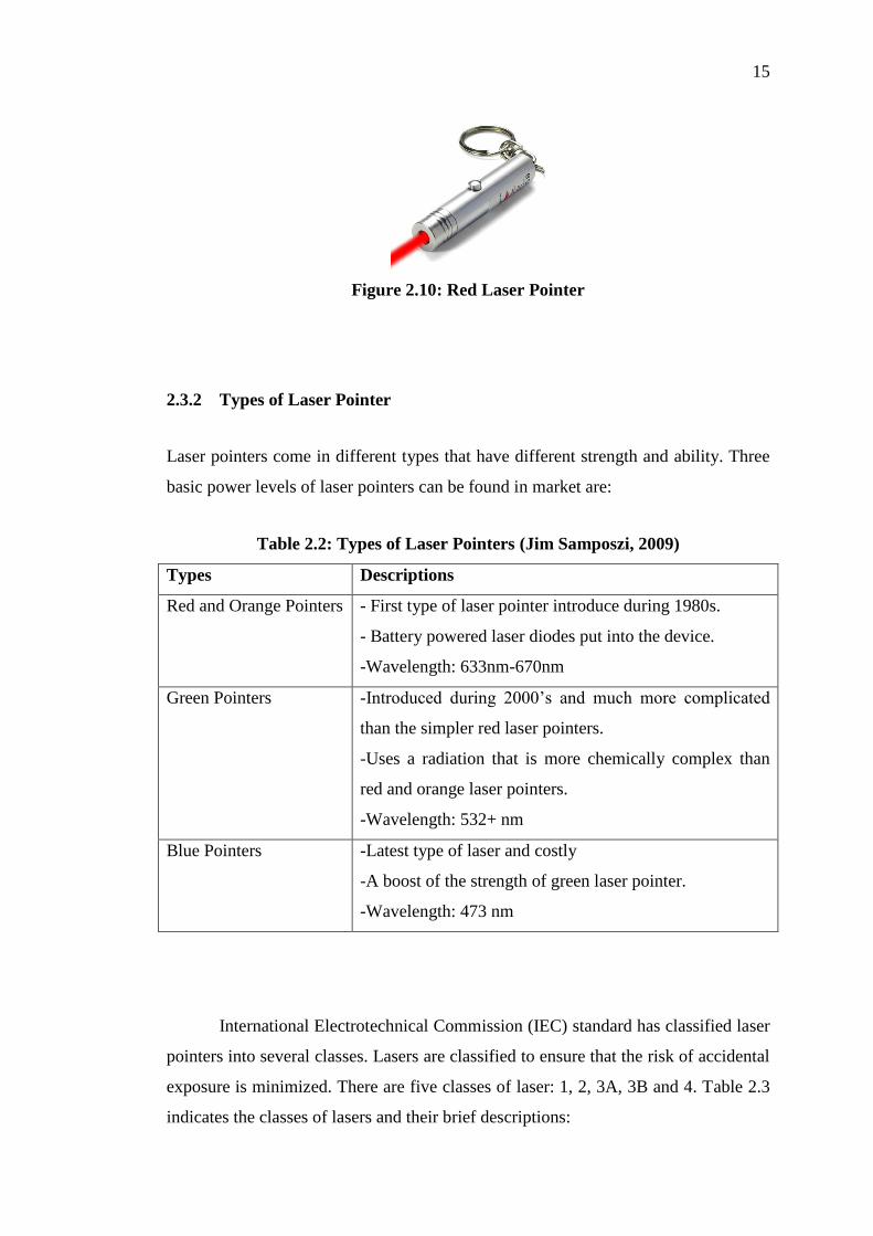
of being a novelty electronics item. Figure 2.10 shows an example of red laser
pointer:
15
Figure 2.10: Red Laser Pointer
2.3.2 Types of Laser Pointer
Laser pointers come in different types that have different strength and ability. Three
basic power levels of laser pointers can be found in market are:
Table 2.2: Types of Laser Pointers (Jim Samposzi, 2009)
Types Descriptions
Red and Orange Pointers - First type of laser pointer introduce during 1980s.
- Battery powered laser diodes put into the device.
-Wavelength: 633nm-670nm
Green Pointers -Introduced during 2000’s and much more complicated
than the simpler red laser pointers.
-Uses a radiation that is more chemically complex than
red and orange laser pointers.
-Wavelength: 532+ nm
Blue Pointers -Latest type of laser and costly
-A boost of the strength of green laser pointer.
-Wavelength: 473 nm
International Electrotechnical Commission (IEC) standard has classified laser
pointers into several classes. Lasers are classified to ensure that the risk of accidental
exposure is minimized. There are five classes of laser: 1, 2, 3A, 3B and 4. Table 2.3
indicates the classes of lasers and their brief descriptions:
16
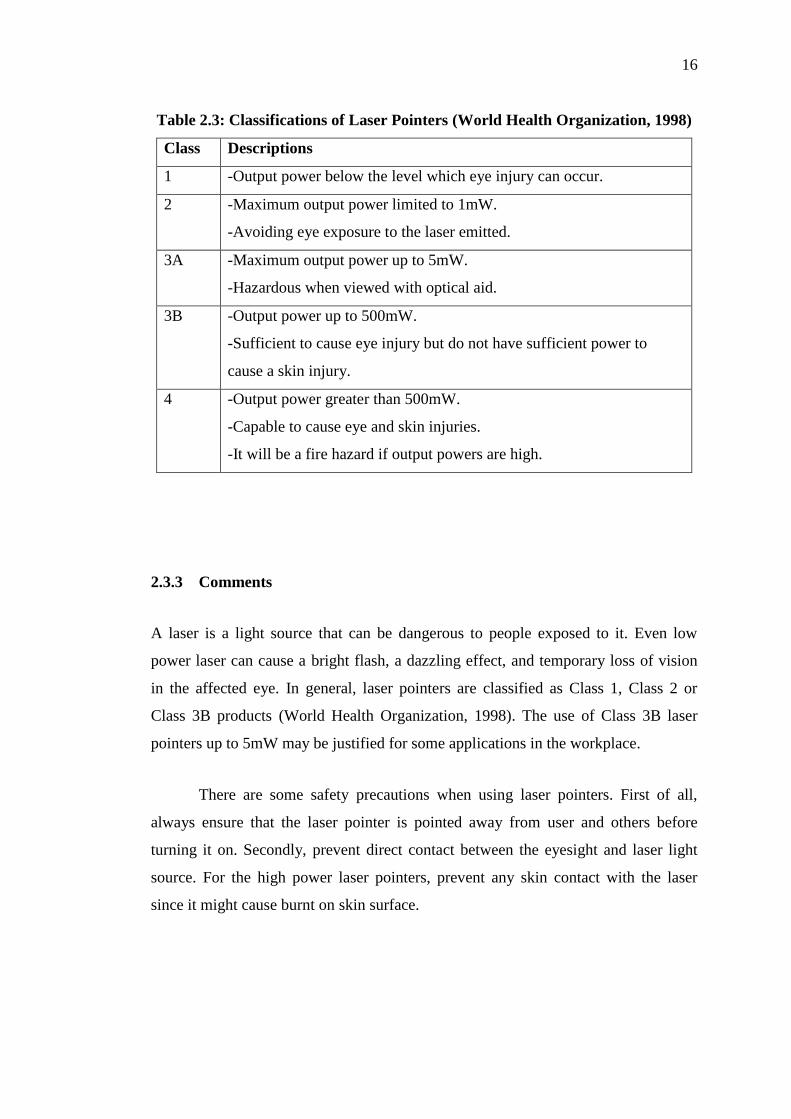
Table 2.3: Classifications of Laser Pointers (World Health Organization, 1998)
Class Descriptions
1 -Output power below the level which eye injury can occur.
2 -Maximum output power limited to 1mW.
-Avoiding eye exposure to the laser emitted.
3A -Maximum output power up to 5mW.
-Hazardous when viewed with optical aid.
3B -Output power up to 500mW.
-Sufficient to cause eye injury but do not have sufficient power to
cause a skin injury.
4 -Output power greater than 500mW.
-Capable to cause eye and skin injuries.
-It will be a fire hazard if output powers are high.
2.3.3 Comments
A laser is a light source that can be dangerous to people exposed to it. Even low
power laser can cause a bright flash, a dazzling effect, and temporary loss of vision
in the affected eye. In general, laser pointers are classified as Class 1, Class 2 or
Class 3B products (World Health Organization, 1998). The use of Class 3B laser
pointers up to 5mW may be justified for some applications in the workplace.
There are some safety precautions when using laser pointers. First of all,
always ensure that the laser pointer is pointed away from user and others before
turning it on. Secondly, prevent direct contact between the eyesight and laser light
source. For the high power laser pointers, prevent any skin contact with the laser
since it might cause burnt on skin surface.
17
2.4 Image Processing
2.4.1 Edge Detection
Edge detection refers to the process of identifying and locating sharp discontinuities
in an image (Raman Maini & Dr. Himanshu Aggarwal). Edge detection is the
beginning step in object recognition, hence it is important to choose an appropriate
edge detection technique by understanding the differences between various
techniques.
Two categories can group the majority of different methods: Gradient based
and Laplacian based Edge Detection. Gradient based method detects the edges by
looking the maximum and minimum in the first order derivative of the image while
Laplacian method searches for zero crossings in the second order derivatives of the
image to find edges (Raman Maini & Dr. Himanshu Aggarwal). Some advantages
and disadvantages of Edge Detection Techniques can be classified in Table 2.4:
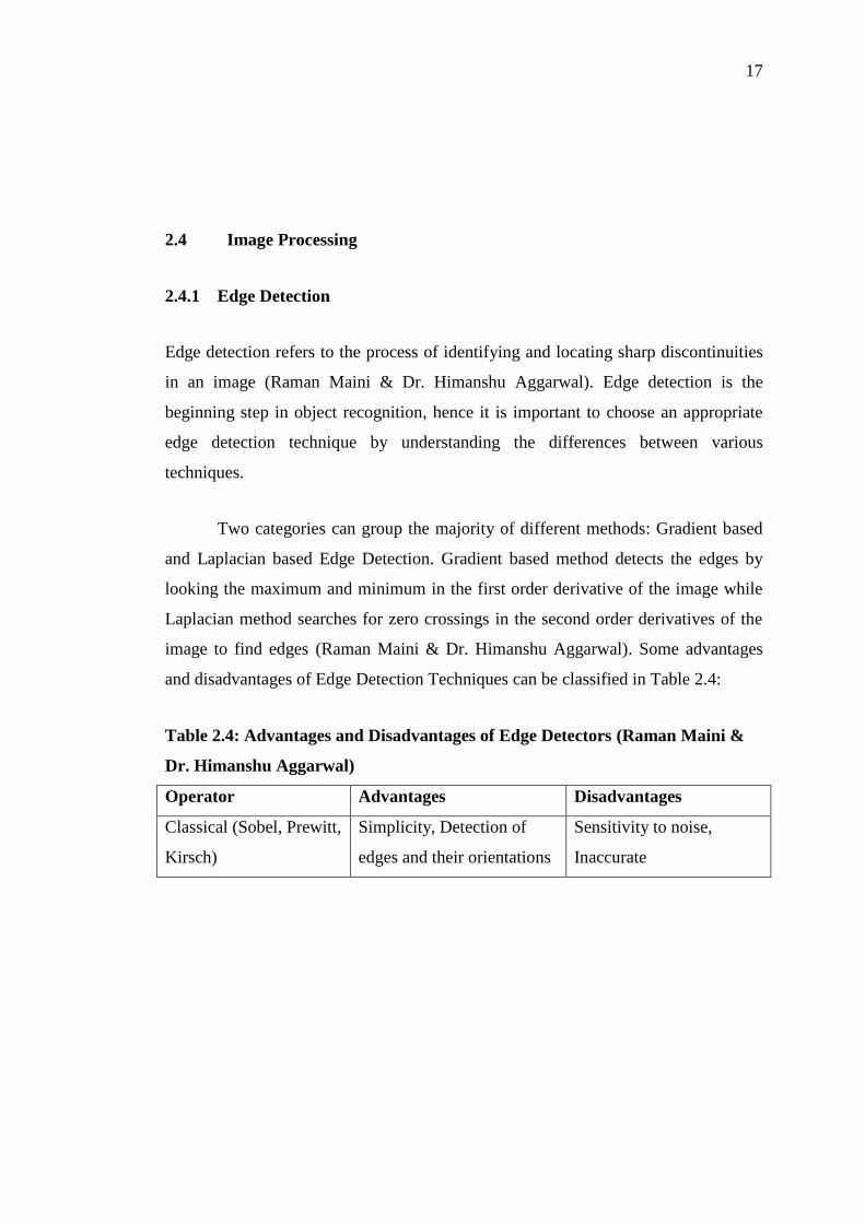
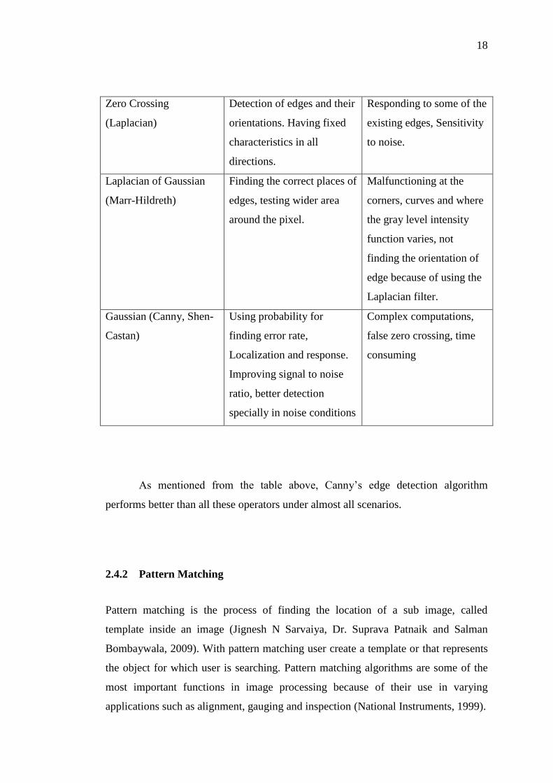
Table 2.4: Advantages and Disadvantages of Edge Detectors (Raman Maini &
Dr. Himanshu Aggarwal)
Operator Advantages Disadvantages
Classical (Sobel, Prewitt,
Kirsch)
Simplicity, Detection of
edges and their orientations
Sensitivity to noise,
Inaccurate
18
Zero Crossing
(Laplacian)
Detection of edges and their
orientations. Having fixed
characteristics in all
directions.
Responding to some of the
existing edges, Sensitivity
to noise.
Laplacian of Gaussian
(Marr-Hildreth)
Finding the correct places of
edges, testing wider area
around the pixel.
Malfunctioning at the
corners, curves and where
the gray level intensity
function varies, not
finding the orientation of
edge because of using the
Laplacian filter.
Gaussian (Canny, Shen-
Castan)
Using probability for
finding error rate,
Localization and response.
Improving signal to noise
ratio, better detection
specially in noise conditions
Complex computations,
false zero crossing, time
consuming
As mentioned from the table above, Canny’s edge detection algorithm
performs better than all these operators under almost all scenarios.
2.4.2 Pattern Matching
Pattern matching is the process of finding the location of a sub image, called
template inside an image (Jignesh N Sarvaiya, Dr. Suprava Patnaik and Salman
Bombaywala, 2009). With pattern matching user create a template or that represents
the object for which user is searching. Pattern matching algorithms are some of the
most important functions in image processing because of their use in varying
applications such as alignment, gauging and inspection (National Instruments, 1999).

19
There are different pattern matching techniques:
Table 2.5: Different Techniques of Pattern Matching
Techniques Comments
Cross Correlation -Correlation process is time consuming.
-Matching process can be speed up by reducing the size
of the image and restricting the region in the image.
Pyramidal Matching -The image and the template can be reduced to ¼ of
their original size.
-Matching is faster.
Scale-Invariant Matching -Good technique for patterns those are not scaled or
rotated.
-Scaled and rotated image will require exhaustive
rotations of the template.
Image Understanding -Speed up the searching process by reduces the amount
of information needed to fully characterize an image or
pattern.
-Include geometric modelling, efficient non-uniform
sampling and extraction of template information that is
rotation and scale independent.
2.4.3 Other Searching Techniques
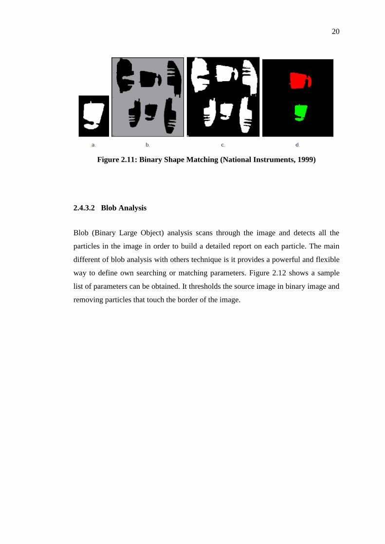
2.4.3.1 Binary Shape Matching
It performed by extracting parameters from a template object that represent the
object’s shape and are invariant to the rotation and scale of the shape (National
Instruments, 1999). Figure 2.11 (a) shows the shape template, Figure 2.11 (b) shows
the original grayscale image, Figure 2.11 (c) shows the binary version of the image
and Figure 2.11 (d) shows the output of the shape matching function.
20
Figure 2.11: Binary Shape Matching (National Instruments, 1999)
2.4.3.2 Blob Analysis
Blob (Binary Large Object) analysis scans through the image and detects all the
particles in the image in order to build a detailed report on each particle. The main
different of blob analysis with others technique is it provides a powerful and flexible
way to define own searching or matching parameters. Figure 2.12 shows a sample
list of parameters can be obtained. It thresholds the source image in binary image and
removing particles that touch the border of the image.

21
Figure 2.12: List of Parameters Extracted from a Particle in a Binary Image
(National Instruments, 1999)
The major drawback of blob analysis is not practical in searching appliation for the
image that have low contract and highly reflective parts.
22
CHAPTER 3
3 METHODOLOGY
3.1 Overview
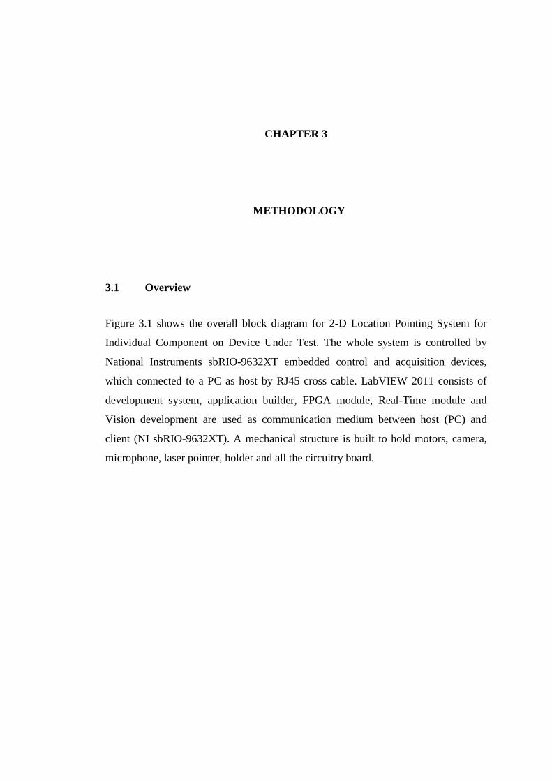
Figure 3.1 shows the overall block diagram for 2-D Location Pointing System for
Individual Component on Device Under Test. The whole system is controlled by
National Instruments sbRIO-9632XT embedded control and acquisition devices,
which connected to a PC as host by RJ45 cross cable. LabVIEW 2011 consists of
development system, application builder, FPGA module, Real-Time module and
Vision development are used as communication medium between host (PC) and
client (NI sbRIO-9632XT). A mechanical structure is built to hold motors, camera,
microphone, laser pointer, holder and all the circuitry board.
23
Figure 3.1: Overall Block Diagram for 2-D Location Pointing System for Individual Component on Device Under Test

24
Most of the devices are connected to NI sbRIO-9632XT board except camera
and microphone. Both of these devices are plugged into USB port of PC. The system
architecture can be simplified into Figure 3.2:
Figure 3.2: Windows User Interface
Graphical Programming will be used in the whole system operation.
LabVIEW 2011 is the software that developed by National Instruments to do the
compilation on graphical programming. The programming concept flow of the
system can be shown in Figure 3.3:

25
Designed LabVIEW Applications
User places the PCB on fixed coordinates
New PCB Board?
Load Template Image
YES
NO
Camera captures
image as template
Browse EAGLE
board into LabVIEW
Camera update
current position of PCB
Compare the coordination
with the image captured
Drive laser pointer
to the desired location
Select component
from schematic
Figure 3.3: Flowchart of System Programming Concept
26
3.2 Mechanical Structure
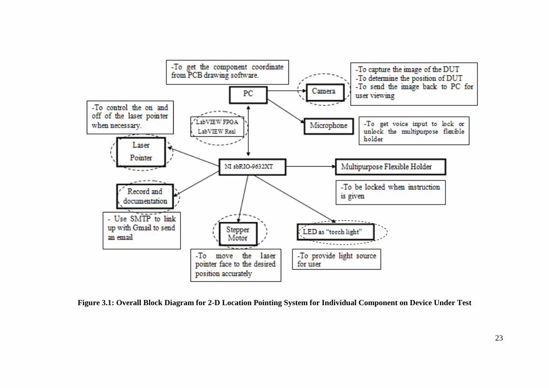
Figure 3.4: Draft Mechanical Structure Design
The main material use for the structure is aluminium angle bars with 30cm x 6 and
40cm x 2 length. Two bars are connected by using bolts, washers and nuts. Apart
from that, two stainless steel rods are used to form the tracks for x axis and y axis
movement.
Motors will be mounted on the aluminium angle bars with connection of
rubber belts to opposite edge. Figure 3.4 shows the mechanical structure design of
the system. Gears are mounted on motors’ shaft so it can drive the rubber to move
the laser pointer in one direction.
27
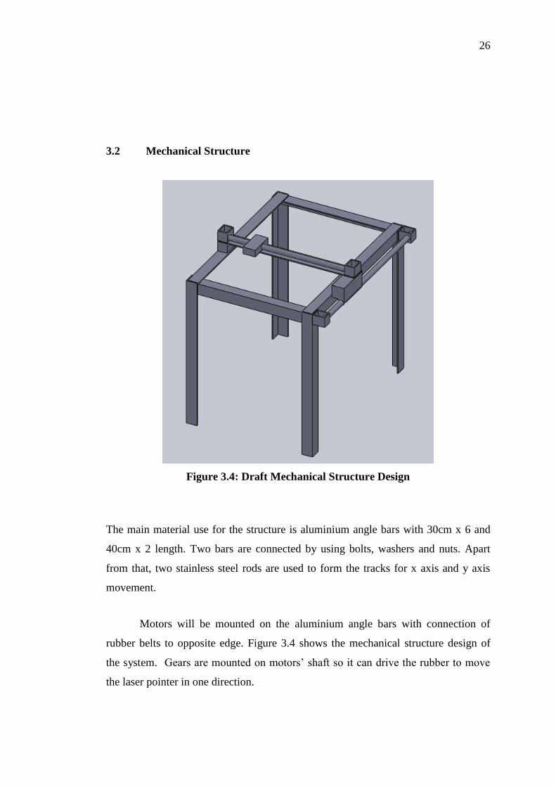
3.3 NI sbRIO-9632XT
National Instruments Single-Board Reconfigurable I/O device is an embedded
control and acquisition device with the integration of real-time processor, FPGA, and
I/O on a single printed circuit board. Figure 3.5 shows the image of NI sbRIO-
9632XT:
Figure 3.5: NI sbRIO-9632XT Front View
NI sbRIO-9632XT devices are designed to be easily embedded in high-volume
applications that require flexibility, high performance, and reliability. (National
Instruments, 2011) In the project, NI sbRIO-9632XT, is the communication medium
between PC and all electronic devices. NI sbRIO-9632XT provides sufficient digital
and analog I/O pins for the system. The electronic devices mentioned are listed in the
Table 3.1:
28
Table 3.1: List of I/O Table for System
Devices Number of I/O pins needed
Motors x2 10
LED 8
LCD display 6
Switches 8
Flexible holder 1
Laser Pointer 1
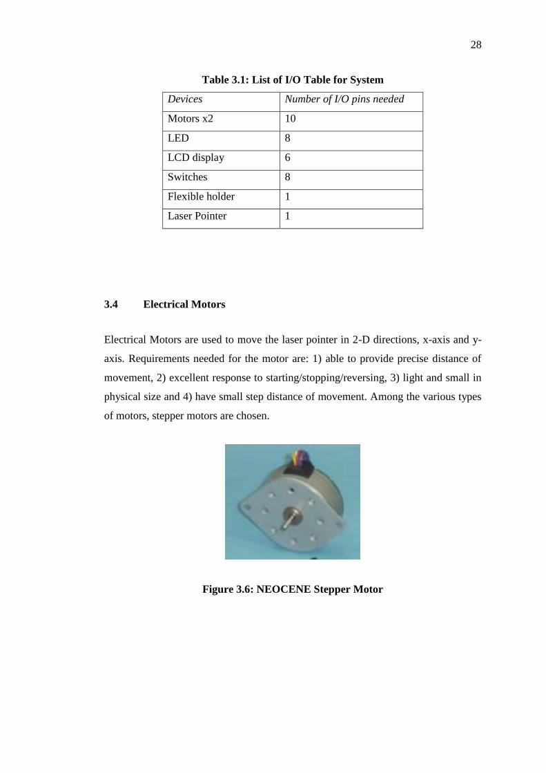
3.4 Electrical Motors
Electrical Motors are used to move the laser pointer in 2-D directions, x-axis and y-
axis. Requirements needed for the motor are: 1) able to provide precise distance of
movement, 2) excellent response to starting/stopping/reversing, 3) light and small in
physical size and 4) have small step distance of movement. Among the various types
of motors, stepper motors are chosen.
Figure 3.6: NEOCENE Stepper Motor
29
Table 3.2: Neocene 2T357247
Type NTC PM-type Stepper Motor
Motor outer diameter 35mm
Step angle 3.75o
Height 8.3mm
Number of wire 5
The motor provides a step angle of 3.75o
, which is relatively small that the
movement can reach few millimetres only. The stepper motor contains five wires:
four input wires from respective winding and one ground wire. The sequence of the
inputs needs to be identified so the motor can rotate smoothly in either clockwise or
anticlockwise direction.
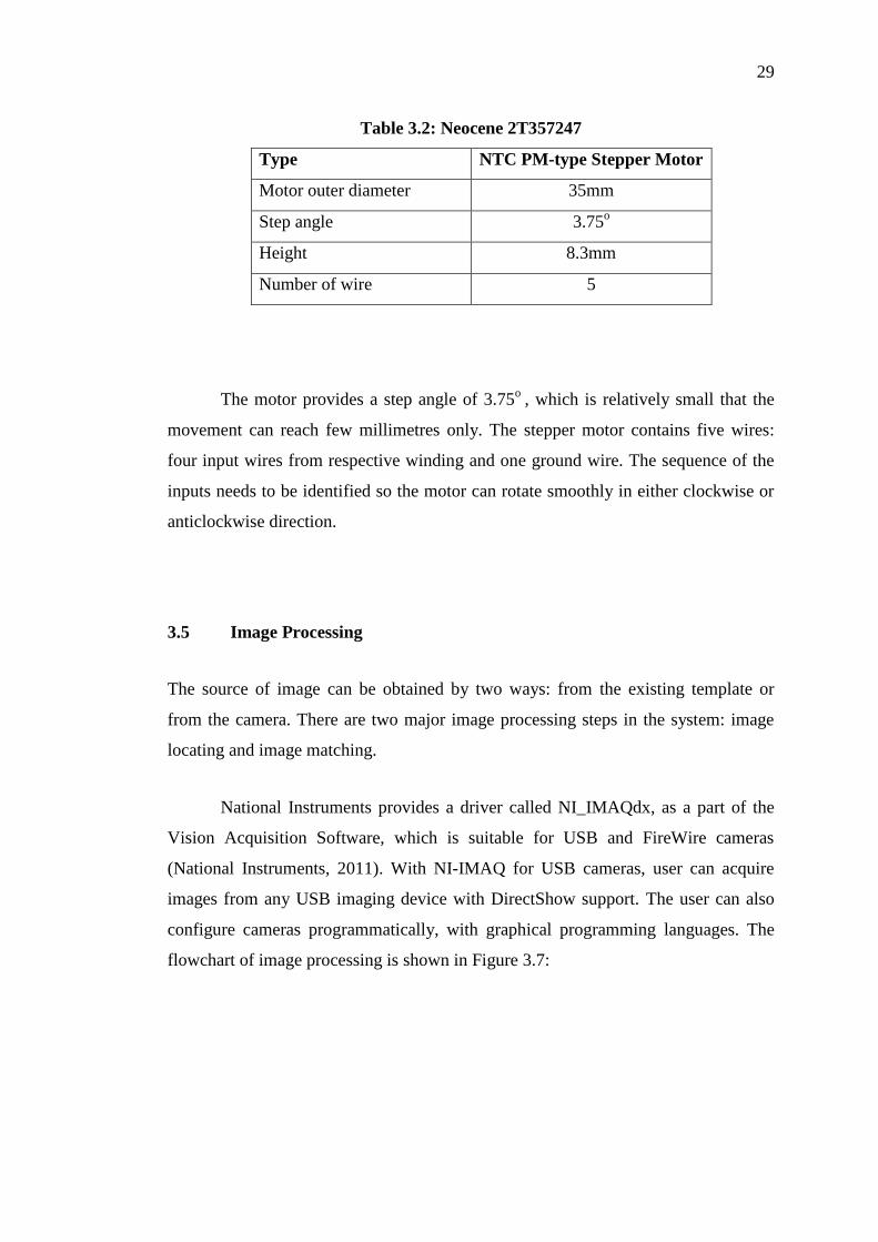
3.5 Image Processing
The source of image can be obtained by two ways: from the existing template or
from the camera. There are two major image processing steps in the system: image
locating and image matching.
National Instruments provides a driver called NI_IMAQdx, as a part of the
Vision Acquisition Software, which is suitable for USB and FireWire cameras
(National Instruments, 2011). With NI-IMAQ for USB cameras, user can acquire
images from any USB imaging device with DirectShow support. The user can also
configure cameras programmatically, with graphical programming languages. The
flowchart of image processing is shown in Figure 3.7:
30
DUT placed on the preset
location on the surface
User entering the
name of DUT
The name existed?
Retrieve template from folder Create new folder
YES NO
Image of DUT captured
Locate and clamp the template
by edge detection
Store/ Update
template in the folder
User search for
particular component
Perform pattern matching
with template
Image of DUT captured
Update new location of DUT
Exit?
End
YES
NO
Figure 3.7: Procedure of Image Processing

31
3.5.1 Template Locate
In LabVIEW Vision Acquisition Software, functions that related to image locating
are IMAQ Clamp Horizontal VI, IMAQ Clamp Vertical VI, IMAQ Edge Detection
VI and IMAQ Edge Detection VI.
For the system, IMAQ Clamp Horizontal and Vertical are used. The reason is
it provide the x-axis distance between two lines when hit-line to the object through
the leftmost edge and another hit-line from rightmost edge, while y-axis distance
when hit-line from uppermost and lowermost edge are calculated. In addition, edge
coordinates are also provides after perform IMAQ clamp functions.
From the results of image clamping, it is able to identify what is the size of
the DUT, the resultant image and the coordinates of four respective edges. If the user
moves the DUT, the information of clamping functions can pass to next functions to
perform relocation, which will be discussed in next subtopic.
Figure 3.8: IMAQ Clamp Vertical Max VI (LabVIEW 2011)
32
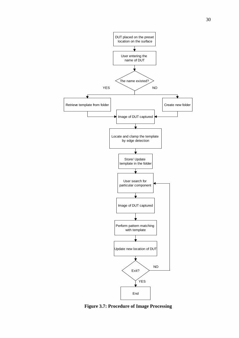
3.5.2 Image Relocation
It is important to detect the location of the object in order to update the latest
location’s coordinates. To detect new location, the parameters of the template have to
be learned by the function in LabVIEW. This is the reason why template is obtained
at earlier stage.
After create a quality template, the pattern matching algorithm has to learn
the important features of the template. The learning process usually time intensive
because the algorithm attempts to find unique features of the template that allow for
fast, accurate matching. The parameters that influence the IMAQ Vision pattern
matching algorithm are match mode, minimum contrast and rotation angle ranges.
LabVIEW does provide several types of searching and matching functions
such as colour pattern matching, and geometric pattern matching. Pattern matching is
chosen to locate object it is because DUT is not a symmetrical in shape and each
components on the DUT has unique identity.
Figure 3.9: Example of Pattern Matching
33
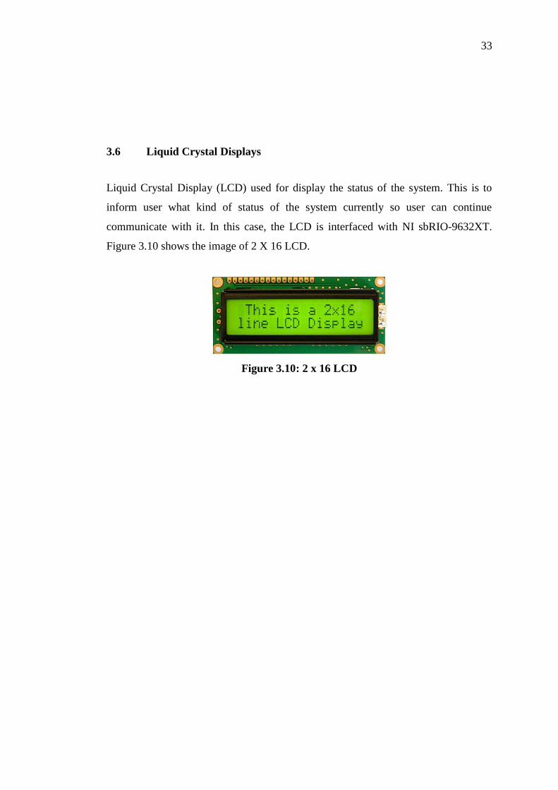
3.6 Liquid Crystal Displays
Liquid Crystal Display (LCD) used for display the status of the system. This is to
inform user what kind of status of the system currently so user can continue
communicate with it. In this case, the LCD is interfaced with NI sbRIO-9632XT.
Figure 3.10 shows the image of 2 X 16 LCD.
Figure 3.10: 2 x 16 LCD

34
CHAPTER 4
4 IMPLEMENTATION OF SYSTEM AND OUTCOMES
4.1 Overall Implementation
The physical design of the 2-D Location Pointing System is implemented as shown
in Figure 4.1 and Figure 4.2. The labels of the figures are shown in Figure 4.3:
Figure 4.1: Side View of the System
3
4
1
2
6
5

35
Figure 4.2: Plan View of the System
Table 4.1: List of Devices
Number Device
1 Y-axis Stepper Motor
2 Super Bright White LED
3 NI sbRIO-9632XT
4 LED Indicators
5 Switches
6 2x16 LCD
7 X-axis Stepper Motor
8 Laser Pointer
9 C170 Logitech Webcam
7
9
8
36
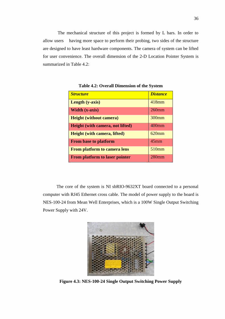
The mechanical structure of this project is formed by L bars. In order to
allow users having more space to perform their probing, two sides of the structure
are designed to have least hardware components. The camera of system can be lifted
for user convenience. The overall dimension of the 2-D Location Pointer System is
summarized in Table 4.2:
Table 4.2: Overall Dimension of the System
Structure Distance
Length (y-axis) 418mm
Width (x-axis) 260mm
Height (without camera) 300mm
Height (with camera, not lifted) 400mm
Height (with camera, lifted) 620mm
From base to platform 45mm
From platform to camera lens 510mm
From platform to laser pointer 280mm
The core of the system is NI sbRIO-9632XT board connected to a personal
computer with RJ45 Ethernet cross cable. The model of power supply to the board is
NES-100-24 from Mean Well Enterprises, which is a 100W Single Output Switching
Power Supply with 24V.
Figure 4.3: NES-100-24 Single Output Switching Power Supply

37
4.2 Hardware Design Architecture
All hardware except image capturing device, are controlled by LabVIEW FPGA. The
details connections of NI sbRIO-9632XT shown in Table 4.3:
Table 4.3: Devices Input/Output Connections on NI sbRIO-9632XT
Port Devices Functions
Port 4/ DIO 3
2x16 LCD
R/S
Port 4/ DIO 4 EN
Port 4/ DIO 5 R4
Port 4/ DIO 6 R5
Port 4/ DIO 7 R6
Port 4/ DIO 8 R7
Port 7/DIO 0 LED Indicates Error
Port 7/DIO 1 LED Indicates System in Progress
Port 7/DIO 2 LED Indicates Template Availability
Port 7/DIO 3 LED Indicates User can Select Component
Port 3/DIO 9 LED Indicates Motors Back to Origin
Port 3/DIO 0 LED Indicates Object Detected
Port 3/DIO 1 LED Reserved
Port 3/DIO 2 LED Reserved
38
Port 9/DIO 1
Stepper Motor
Provide sequential output for y-axis
movement
Port 9/DIO 2
Port 9/DIO 3
Port 9/DIO 4
Port 9/DIO 5
Stepper Motor
Provide sequential output for x-axis
movement
Port 9/DIO 6
Port 9/DIO 7
Port 9/DIO 8
Port 8/DIO 7 Lever Switch Stop motor movement at the x-axis edge
Port 8/DIO 8 Lever Switch Stop motor movement at the y-axis edge
Port 9/DIO 0 Laser Pointer Points to search result
Port 9/DIO 9 White LEDs Provide lightings
Port 4/DIO 0 Push Button Motor Back to Origin
Port 4/DIO 1 Push Button Relocate Object
Port 4/DIO 2 Push Button Control Laser on/off
Port 4/DIO 9 Toggle Switch Control Lightings
Port 3/DIO 7 Toggle Switch Reserved
Port 3/DIO 8 Toggle Switch Reserved
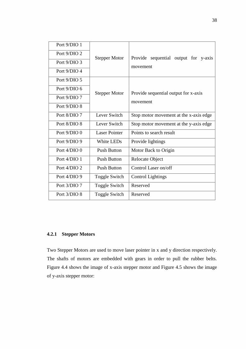
4.2.1 Stepper Motors
Two Stepper Motors are used to move laser pointer in x and y direction respectively.
The shafts of motors are embedded with gears in order to pull the rubber belts.
Figure 4.4 shows the image of x-axis stepper motor and Figure 4.5 shows the image
of y-axis stepper motor:

39
Figure 4.4: X-axis Stepper Motor
Figure 4.5: Y-axis Stepper Motor
The Input/Output ports from NI sbRIO-9632XT are not sufficient to provide
current to both of the stepper motors. Hence, high current Darlington transistor array
ULN2803 used to drive stepper motor with the input voltage 24V, with the ports
connections showed in Figure 4.6:
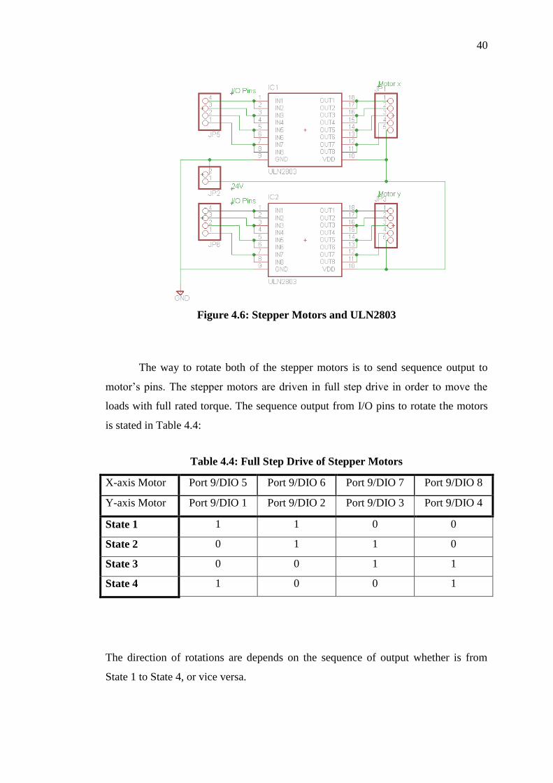
40
Figure 4.6: Stepper Motors and ULN2803
The way to rotate both of the stepper motors is to send sequence output to
motor’s pins. The stepper motors are driven in full step drive in order to move the
loads with full rated torque. The sequence output from I/O pins to rotate the motors
is stated in Table 4.4:
Table 4.4: Full Step Drive of Stepper Motors
X-axis Motor Port 9/DIO 5 Port 9/DIO 6 Port 9/DIO 7 Port 9/DIO 8
Y-axis Motor Port 9/DIO 1 Port 9/DIO 2 Port 9/DIO 3 Port 9/DIO 4
State 1 1 1 0 0
State 2 0 1 1 0
State 3 0 0 1 1
State 4 1 0 0 1
The direction of rotations are depends on the sequence of output whether is from
State 1 to State 4, or vice versa.

41
In order to obtain required distance of rotation in x and y axis, the step
number of motors have to be calibrated. Table 4.5 and 4.6 shows the reading between
distance and number of steps, and their errors.
Table 4.5: Experiment on X-axis Stepper Motor
Steps 10 50 100 200
Distance(mm) 3 18 37 75
Steps/Distance(mm-1
) 3.33 2.78 2.70 2.67
Error Percentage (%) 16.03 3.14 5.92 6.97
Average Steps/Distance =2.87mm-1
Full movement length =180mm
Number of steps needed = 480 steps
Approximate steps per 10mm = 27steps
Table 4.6: Experiment on Y-axis Stepper Motor
Steps 100 200 500 1000
Distance(mm) 2 4 10 21
Steps/Distance(mm-1
) 50.00 50.00 50.00 47.62
Error Percentage (%) 1.19 1.19 1.19 3.62
Average Steps/Distance =49.41mm-1
Full movement length = 300mm
Number of steps needed = 14100 steps
Approximate steps per 10mm = 500 steps
From the experiments, the motors can be precisely stop at require distance in range
of milimeter. In order to reduce the errors in range, two motors have to be returned to
the initial position. Lever switches are act as an indicator to stop the motor at the
initial position which is 0,0 in coordinate. The lever switches schematic is shown in
Figure 4.7:

42
Figure 4.7: Lever Switch Circuit
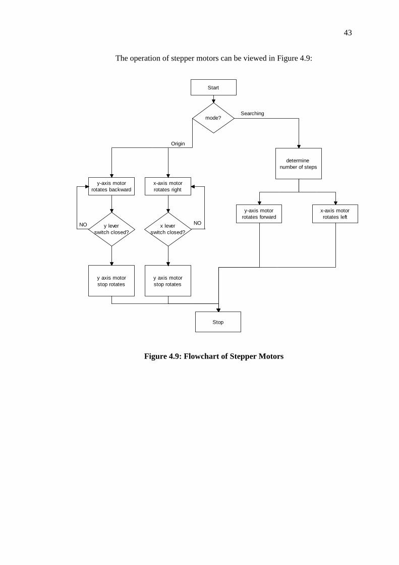
The functions of stepper motors are coded into a module called “motor
run.vi”, which allow designer to determine three functions which are the mode
(searching or back to origin point), x-axis motor steps and y-axis motor steps. The
“motor_run.vi” module is shown in Figure 4.8:
Figure 4.8: “motor run.vi” Module
43
The operation of stepper motors can be viewed in Figure 4.9:
Start
mode?
y-axis motor
rotates backward
x-axis motor
rotates right
Origin
Searching
y-axis motor
rotates forward
x-axis motor
rotates left
y lever
switch closed?
x lever
switch closed?
NONO
y axis motor
stop rotates
y axis motor
stop rotates
determine
number of steps
Stop
Figure 4.9: Flowchart of Stepper Motors
44
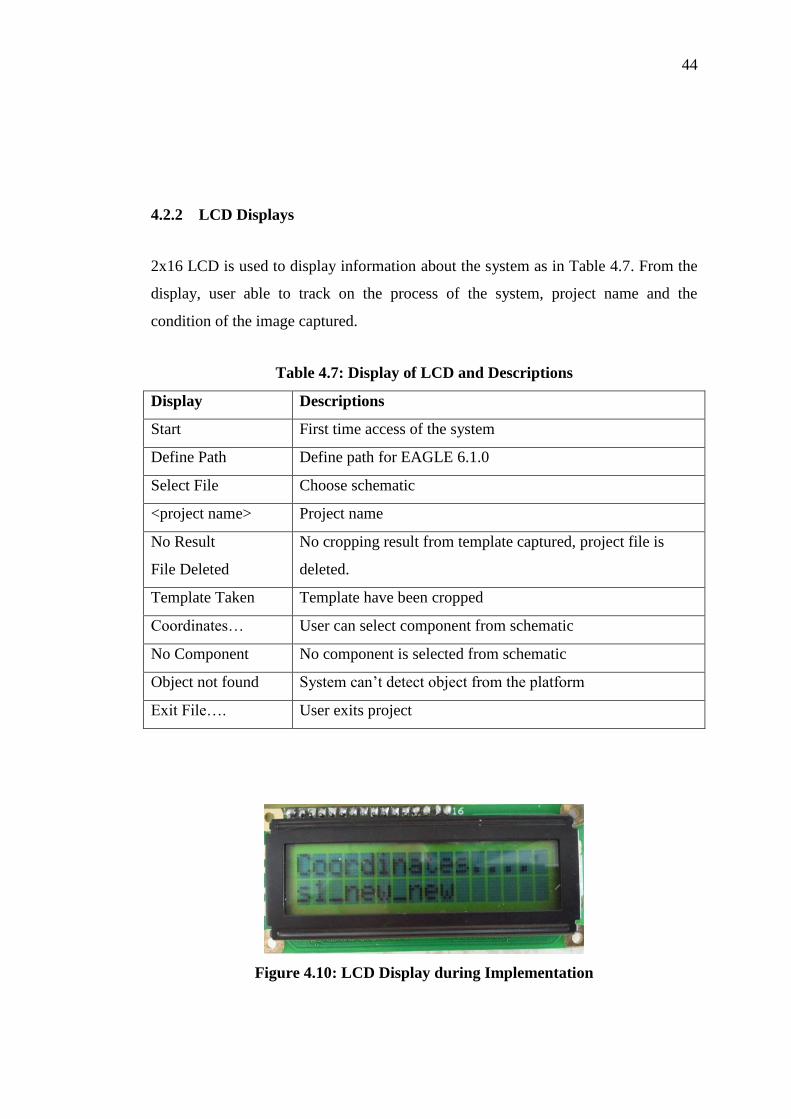
4.2.2 LCD Displays
2x16 LCD is used to display information about the system as in Table 4.7. From the
display, user able to track on the process of the system, project name and the
condition of the image captured.
Table 4.7: Display of LCD and Descriptions
Display Descriptions
Start First time access of the system
Define Path Define path for EAGLE 6.1.0
Select File Choose schematic
<project name> Project name
No Result
File Deleted
No cropping result from template captured, project file is
deleted.
Template Taken Template have been cropped
Coordinates… User can select component from schematic
No Component No component is selected from schematic
Object not found System can’t detect object from the platform
Exit File…. User exits project
Figure 4.10: LCD Display during Implementation

45
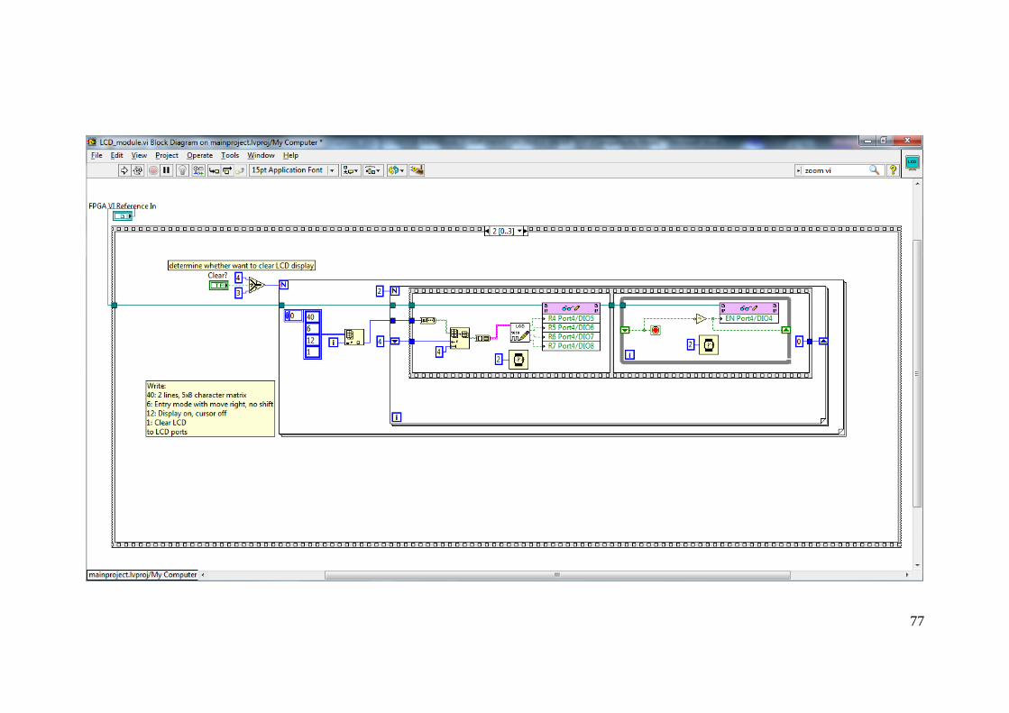
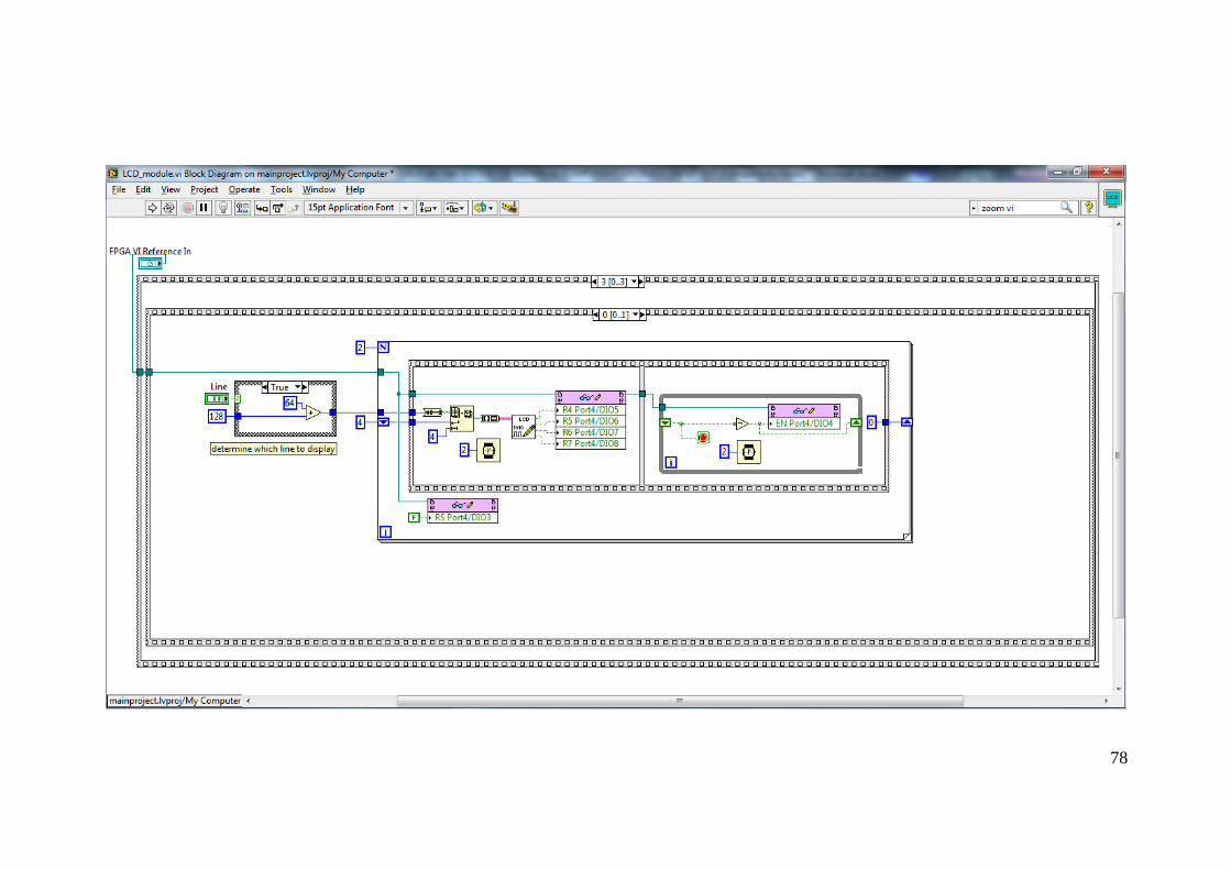
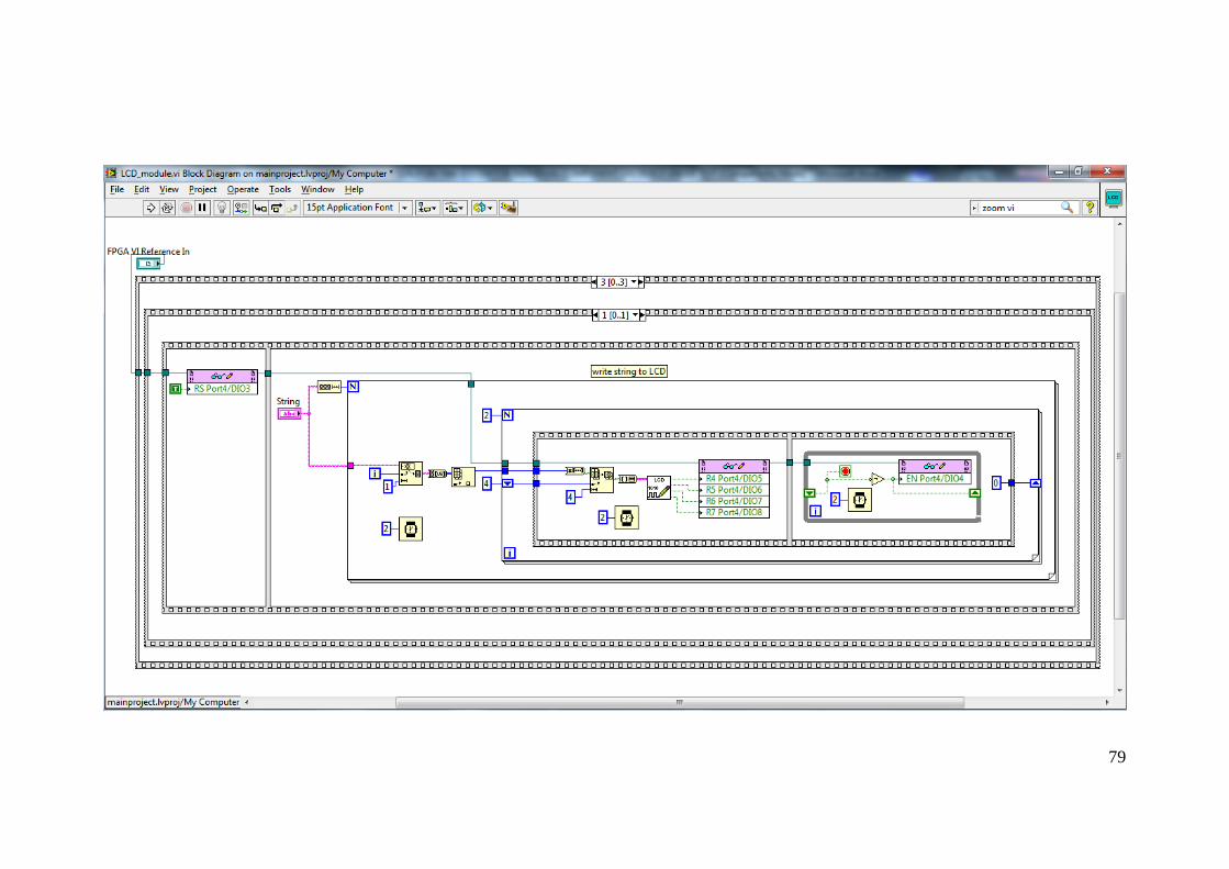
The LCD display module as shown in Figure 4.11 allows designer to determine
whether the previous display need to be cleared, or whether the string displayed in
first or second row.
Figure 4.11: "LCD module.vi" Module
4.2.3 Hardware Controls and Indications
External controls are designed to provide user extra options in control lighting, laser
and motors’ movement. This is shown in Figure 4.12. RC circuits are designed in
order to prevent contact bouncing of the switches. The value of resistor is 10k ohm
while the value of capacitor is 0.1µF:
Figure 4.12: Physical Switches of the System
Indicators provide specific information on the situations of the system. Figure
4.13 shows available LED indicators in the system. Resistors 1k ohms are connected
in series with LED to limit current flow from 3.3V output ports. Current drawn from
each LED has to be less than 3mA from each digital port as stated in NI sbRIO-
9632XT User Guide.

46
Figure 4.13: LED Indicators of the System
Eight super bright white LED are used to provide lighting to the system. High
current Darlington transistors array ULN2803 is needed to provide larger power to
LEDs, with the circuit design showed in Figure 4.14:
Figure 4.14: Circuit Design for LED Lighting System

47
4.2.4 Laser Pointer
Laser Pointer is controlled manually by user. It is embedded in the foam form of
polyethylene, which on the track of x-axis. Table 4.8 shows the characteristics of the
laser pointer and Figure 4.15 shows the image of laser pointer from the system:
Table 4.8: Characteristics of Laser Pointer
Characters Unit
Model HLM1230
Maximum Power 5mW
Input Voltage 3.5-4.5Vdc
Wavelength 650nm
Class 3A
Colour Red
Figure 4.15: Laser Pointer Embedded in Polyethylene
48
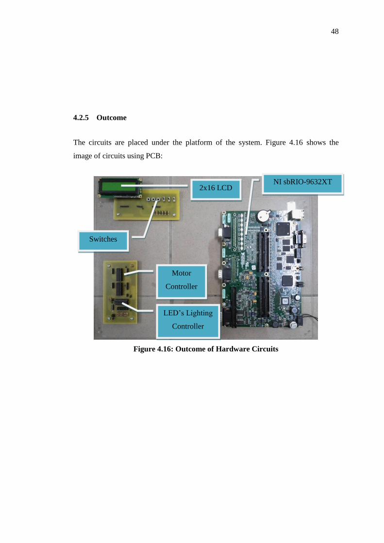
4.2.5 Outcome
The circuits are placed under the platform of the system. Figure 4.16 shows the
image of circuits using PCB:
Figure 4.16: Outcome of Hardware Circuits
NI sbRIO-9632XT
Switches
2x16 LCD
Motor
Controller
LED’s Lighting
Controller
49
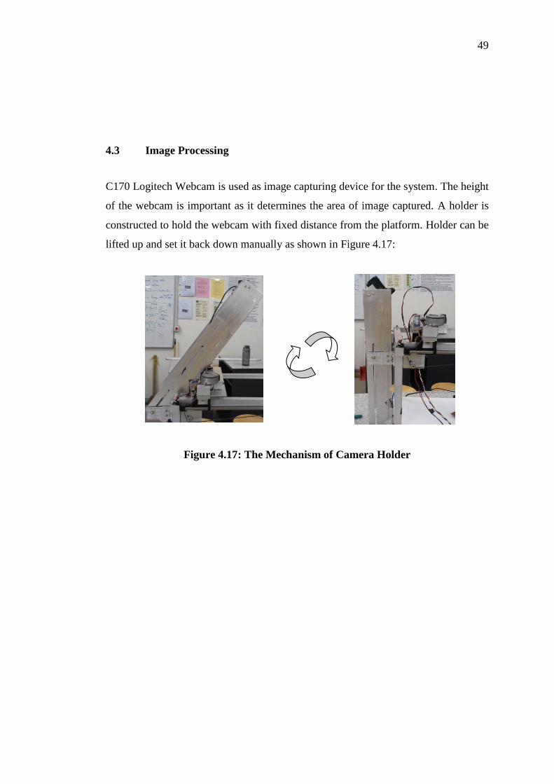
4.3 Image Processing
C170 Logitech Webcam is used as image capturing device for the system. The height
of the webcam is important as it determines the area of image captured. A holder is
constructed to hold the webcam with fixed distance from the platform. Holder can be
lifted up and set it back down manually as shown in Figure 4.17:
Figure 4.17: The Mechanism of Camera Holder

50
The working principle of image processing includes template processing and
pattern matching is shown in Figure 4.18:
Image Capturing
User Investigate Image
Obtain Coordinates
of Clamping Results
Make the image
as template?
Perform Vertical and
Horizontal Edge Clamping
NO
YES
Convert Coordinates to ROI
Extract Image from ROI
Set as template
Image Capturing
Get template
Obtain Information
from template
Perform pattern matching
Run the motorsDisplay "Object Not Found"
message
Object Match?
YES NO
Exit VI
Exit VI
StartStart
( i ) ( ii )
Figure 4.18: Working Principle of Image Processing, (i) Template Processing, (ii)
Pattern Matching

51
4.3.1 Template Processing
A template is needed to locate the DUT. In order to get a good quality of template
and increase accuracy of pointing system, DUT have to be placed in parallel with x
and y axis of image captured by camera. Horizontal and Vertical Clamping functions
are used to obtain the edges coordination of the object captured. The above process
only repeated for every new DUT. Figure 4.19 shows a good quality template and
Figure 4.20 shows a bad quality template:
Figure 4.19: Good Quality Template
52
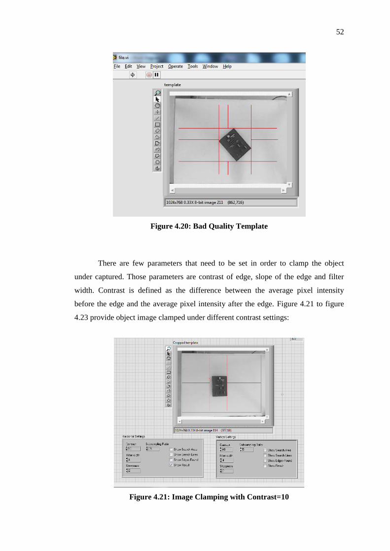
Figure 4.20: Bad Quality Template
There are few parameters that need to be set in order to clamp the object
under captured. Those parameters are contrast of edge, slope of the edge and filter
width. Contrast is defined as the difference between the average pixel intensity
before the edge and the average pixel intensity after the edge. Figure 4.21 to figure
4.23 provide object image clamped under different contrast settings:
Figure 4.21: Image Clamping with Contrast=10

53
Figure 4.22: Image Clamping with Contrast=50
Figure 4.23: Image Clamping with Contrast=100
4.3.2 Pattern Matching Implementation
In order to locate an object regarding its edges within the active region of platform,
pattern matching module is used in system implementation. Before perform pattern
matching, the quality of template need to be good so the accuracy of matching is
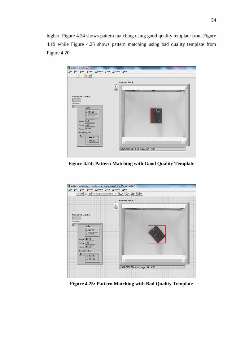
54
higher. Figure 4.24 shows pattern matching using good quality template from Figure
4.19 while Figure 4.25 shows pattern matching using bad quality template from
Figure 4.20:
Figure 4.24: Pattern Matching with Good Quality Template
Figure 4.25: Pattern Matching with Bad Quality Template
55
The parameters need to setup the pattern matching module are templates,
number of matches requested, minumum match score and match mode. Templates
are the images that cropped from the clamping function, discussed in template
processing. Next, number of matches requested is set to one and the match mode set
to Rotation Invariant instead of Shift Invariant. Rotation Invariant allows the
searches for the template in the image regardless of the rotation of the template.
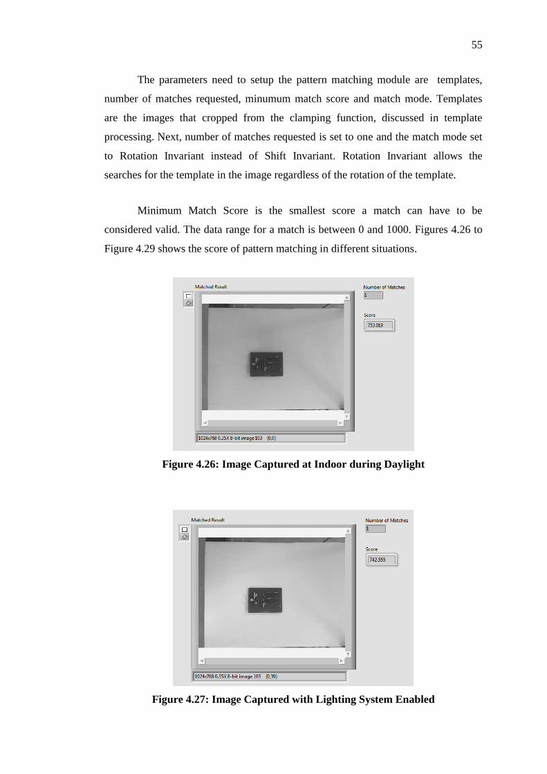
Minimum Match Score is the smallest score a match can have to be
considered valid. The data range for a match is between 0 and 1000. Figures 4.26 to
Figure 4.29 shows the score of pattern matching in different situations.
Figure 4.26: Image Captured at Indoor during Daylight
Figure 4.27: Image Captured with Lighting System Enabled

56
Figure 4.28: Image Captured with Interrupt of Extra Object
Figure 4.29: Image Captured with Objects Not Parallel with Platform
The experiments show that the score can at least reach 500 in different kind
of situation. Therefore minimum match score can set to 500 so it can increase the
accuracy of object searching and matching.
57
4.4 Program Flow Implementation
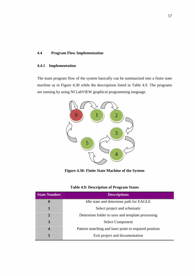
4.4.1 Implementation
The main program flow of the system basically can be summarized into a finite state
machine as in Figure 4.30 while the descriptions listed in Table 4.9. The programs
are running by using NI LabVIEW graphical programming language.
Figure 4.30: Finite State Machine of the System
Table 4.9: Description of Program States
State Number Descriptions
0 Idle state and determine path for EAGLE
1 Select project and schematic
2 Determine folder to save and template processing
3 Select Component
4 Pattern matching and laser point to required position
5 Exit project and documentation
0 1 2
3
4
5
58
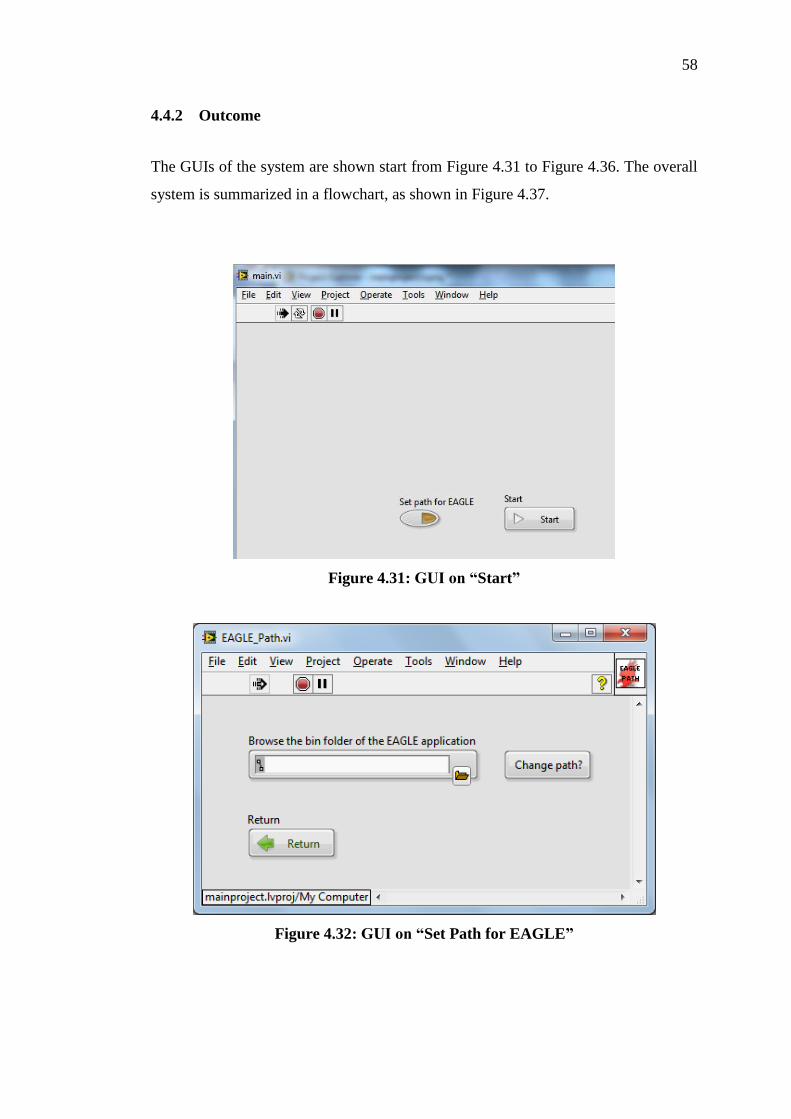
4.4.2 Outcome
The GUIs of the system are shown start from Figure 4.31 to Figure 4.36. The overall
system is summarized in a flowchart, as shown in Figure 4.37.
Figure 4.31: GUI on “Start”
Figure 4.32: GUI on “Set Path for EAGLE”
59
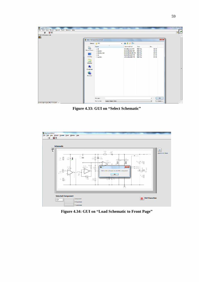
Figure 4.33: GUI on “Select Schematic”
Figure 4.34: GUI on “Load Schematic to Front Page”

60
Figure 4.35: GUI on “Set as Template?”
Figure 4.36: GUI on “Send Searched Components’ Record to Email”

61
Start
Set Path for
EAGLE?
Choose Path
Select Schematic
YES
NO
Retrieve template
from file
Previous file
exist?
YES Create new file
Motors back
origin point
Capture image
Set as template?NO
Load schematic to
front page
Component
selected?
Motors back
origin point
Camera capture image and
perform pattern matching
Template match?Motors back to
require position
YES
NO
NO YES
Exit project
Documentation
NO
Template Clamping
YES
Template
Available?
Project file deleted
NO
YES
Figure 4.37: Program Flow of 2-D Location Pointer

62
CHAPTER 5
5 CONCLUSION AND FUTURE IMPLEMENTATION
As a conclusion, the objectives of the project are met, which is to design a 2-D
Pointing System for individual component on device under test. The system is
designed with the aim that the time consumption can be reduced for user to perform
searching and probing on individual component.
There are few limitations found on the system which can be further improved.
First of all, the current system can only function for DUT front side. The algorithms
can be further improved so that searching for both side of the DUT can be included.
Furthermore, the system can be further designed so that DUT can be turned to either
one side automatically.
Besides that, size of the DUT that can perform under the system is limited
due to the camera is set statically at the top of the system. Further implementation
can be done by modify the camera in order to move in x and y axis. The camera
needs to be able to locate object while moving along the axis. This objective of this
improvement is not only increasing the area to perform, it can also further shrink the
height of the overall physical structure, and useful for image processing since the
image capture is clearer.
Next, the system can be improved so it becomes less dependent to the host
which is computer. It can be modified so NI sbRIO-9632XT acts as host for the
system. Various modifications like USB module, touch screen display and
compatible smart camera can be added to the system. User can easily proceed to the

63
usage of the system without connect to computer and install required software which
is time consuming.

64
REFERENCES
Jignesh N Sarvaiya, Dr. Suprava Patnaik and Salman Bombaywala. (2009). Image
Registration By Template Matching Using Normalized Cross-Correlation.
2009 International Conference on Advances in Computing, Control, and
Telecommunication Technologies, 819.
Jim Samposzi. (2009, August 21). Getting Acquainted with The Many Types of Laser
Pointers. Retrieved December 4, 2011, from Popular Articles:
http://www.populararticles.com/article166765.html
National Instruments. (1999, May). IMAQ Vision User Manual. Pattern Matching,
pp. 9-2.
National Instruments. (2009, February 16). Gmail.VI. Retrieved March 15, 2012,
from National Instruments: http://zone.ni.com/devzone/cda/epd/p/id/5992
National Instruments. (2011, August 10). Acquiring Images in LabVIEW Using a
USB or an IEEE1394 (FireWire) Camera. Retrieved March 15, 2012, from
National Instruments:
http://digital.ni.com/public.nsf/allkb/274A74A901399D0486256F32007295F
9
National Instruments. (2011). Advanced Built-In Analysis and Signal Processing in
NI LabVIEW. Retrieved February 7, 2012, from National Instruments:
http://www.ni.com/labview/whatis/analysis/
National Instruments. (2011). New Features in NI LabVIEW 2011. Retrieved August
8, 2012, from National Instruments:
http://www.ni.com/labview/whatsnew/features/
National Instruments. (2011). NI Single-Board RIO Embedded Control and
Acquisition Devices.
Princeton University. (2010, May 12). Safety Recommendations for Laser Pointers.
Retrieved December 4, 2011, from Environmental Health and Safety,
Princeton University:
http://web.princeton.edu/sites/ehs/labpage/laserpointersafety.htm

65
Raman Maini & Dr. Himanshu Aggarwal. (n.d.). Study and Comparison of Various
Image Edge Detection and Techniques. International Journal of Image
Processing, Volume (3), Issue (1).
Stephen L.Herman. (2009). Electric Motor Control. Delmar Cengage Learning.
World Health Organization. (1998, July ). Health Risks From the Use of Laser
Pointers. Retrieved December 5, 2011, from Fact Sheet No. 202:
https://apps.who.int/inf-fs/en/fact202.html
Integrated Publishing. Synchronised Motors, In: Neets, Module 01, Introduction to
Matter, Erodwellnergy, and Direct Current, Chapter 4, Alternating Current
Motors. 2003. www.tpub.com/content/neets/14177/css/14177_92.htm
Bureau of Energy Efficiency (BEE), Ministry of Power, India. Components of an
Electric Motor. 2005.
www.energymanagertraining.com/equipment_all/electric_motors/eqp_comp_
motors.htm
66
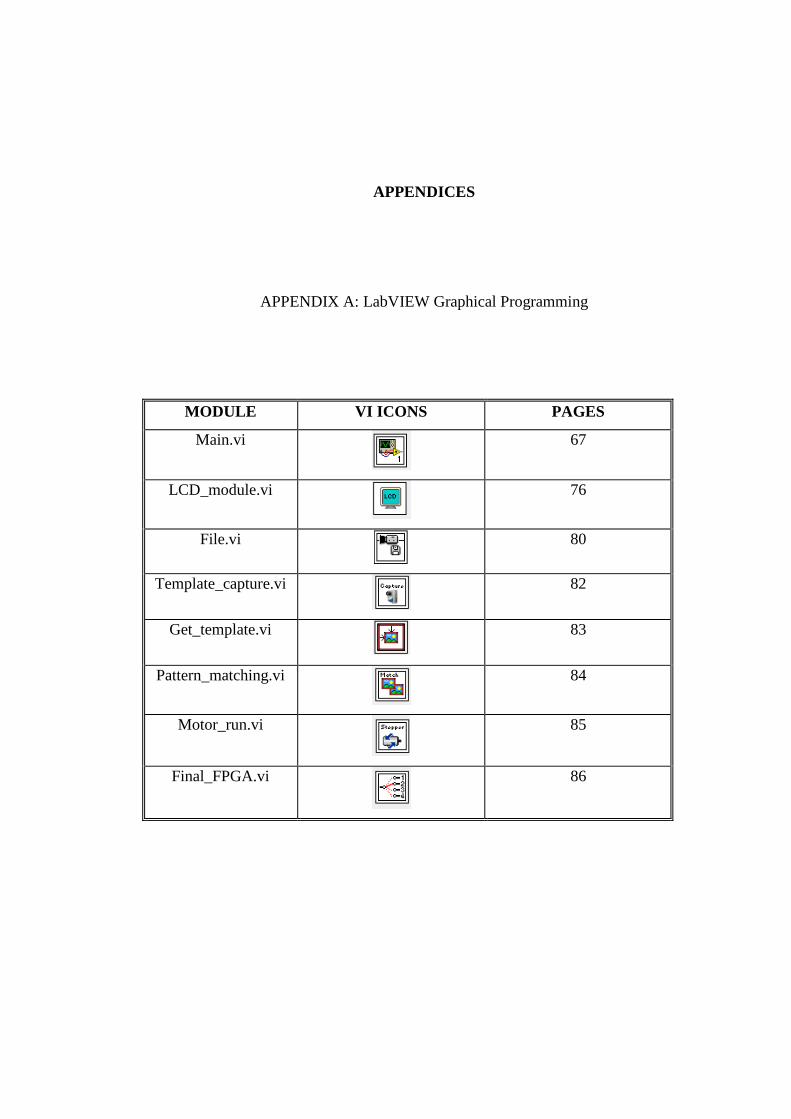
APPENDICES
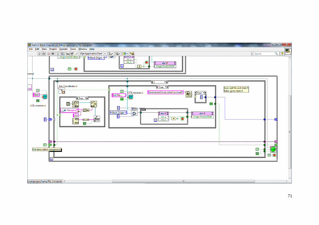
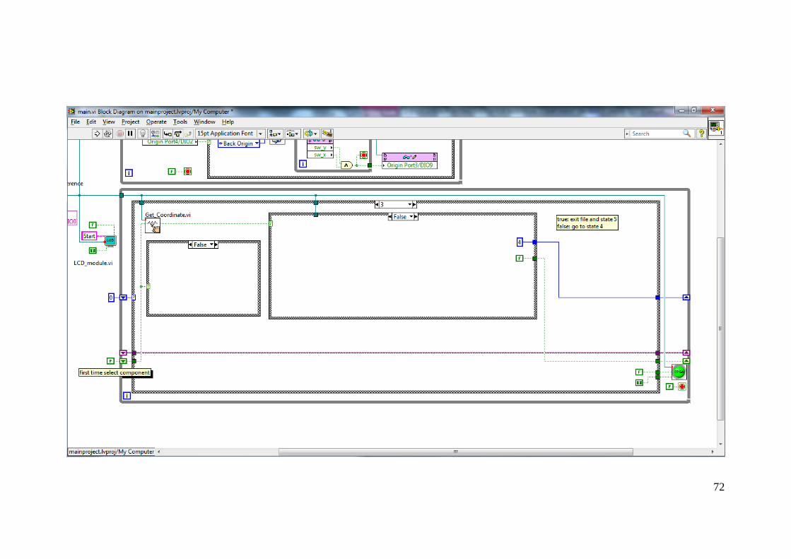
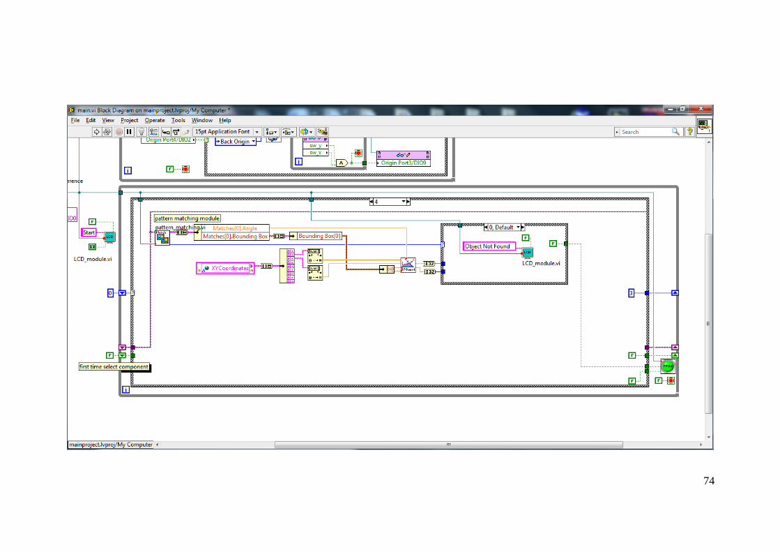
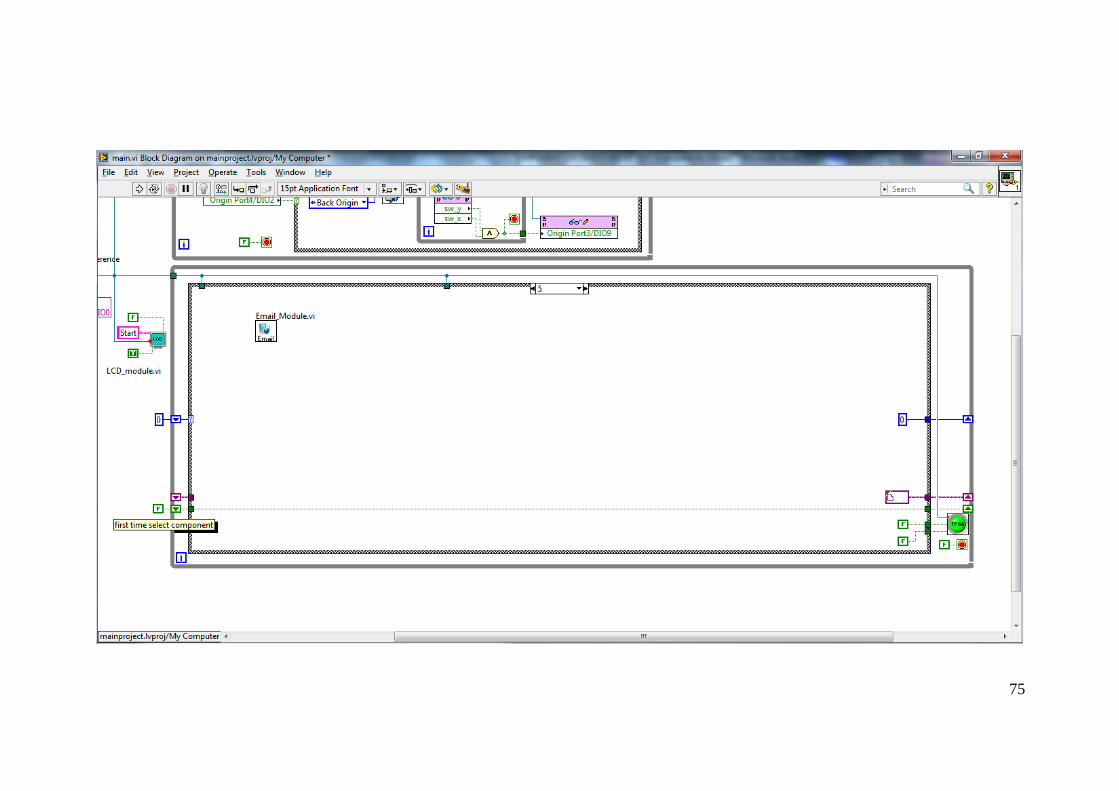
APPENDIX A: LabVIEW Graphical Programming
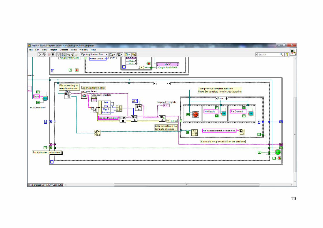
MODULE VI ICONS PAGES
Main.vi
67
LCD_module.vi
76
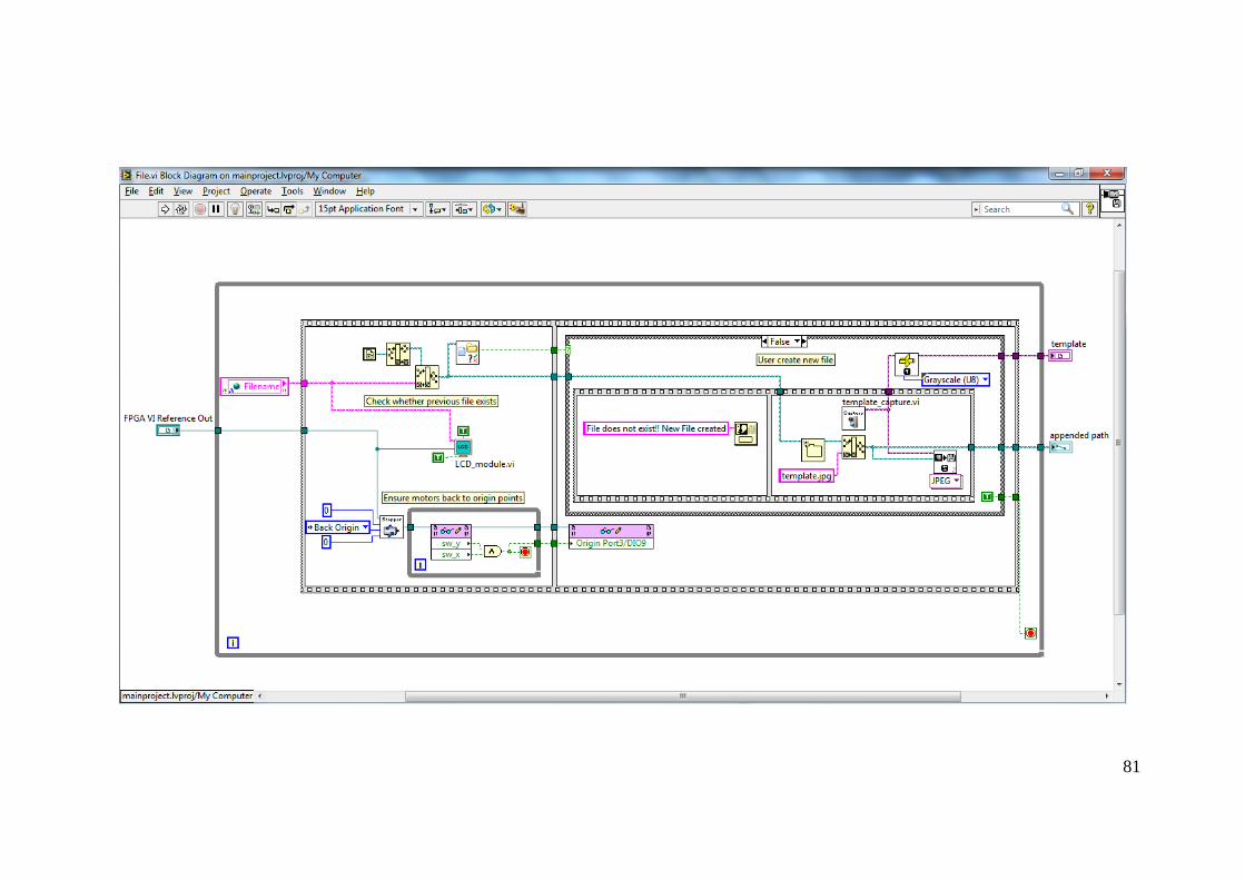
File.vi
80
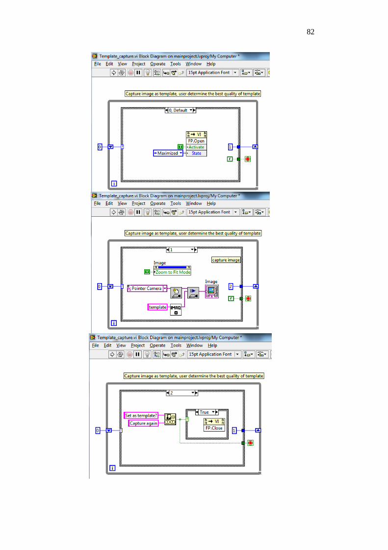
Template_capture.vi
82
Get_template.vi
83
Pattern_matching.vi
84
Motor_run.vi
85
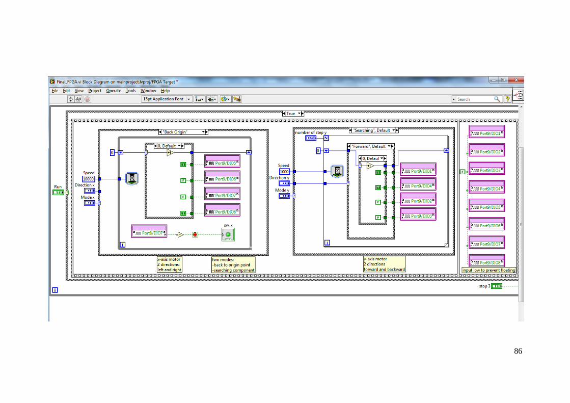
Final_FPGA.vi
86

67

68

69
70
71
72

73
74
75

76
77
78
79

80
81
82

83

84

85
86

87

88
APPENDIX B: Schematic of Motors and Lighting Controllers
89
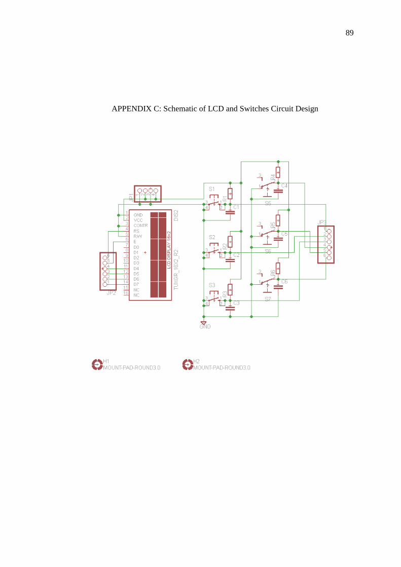
APPENDIX C: Schematic of LCD and Switches Circuit Design

90
APPENDIX D: Schematic of LED Circuit Design