POINTING THE GBT - library.nrao.edulibrary.nrao.edu/public/memos/gbt/GBT_084.pdf · two different...
24
NATIONAL RADIO ASTRONOMY OBSERVATORY Tucson, Arizona POINTING THE GBT J. M. Payne September 16, 1992 This memorandum was written as a basis for discussion for an internal meeting concerning GBT pointing in June 1992. It has been suggested that it be made part of the record by including it in the GBT memo series. Some parts of the memo may now be out of date due to the passage of several months since it was written.
Transcript of POINTING THE GBT - library.nrao.edulibrary.nrao.edu/public/memos/gbt/GBT_084.pdf · two different...

NATIONAL RADIO ASTRONOMY OBSERVATORY Tucson, Arizona
POINTING THE GBT
J. M. Payne
September 16, 1992
This memorandum was written as a basis for discussion for an internal meeting
concerning GBT pointing in June 1992. It has been suggested that it be made part of the
record by including it in the GBT memo series. Some parts of the memo may now be out of
date due to the passage of several months since it was written.
NATIONAL RADIO ASTRONOMY OBSERVATORY Tucson, Arizona
POINTING THE GBT
J. M. Payne September 16, 1992
I. Introduction
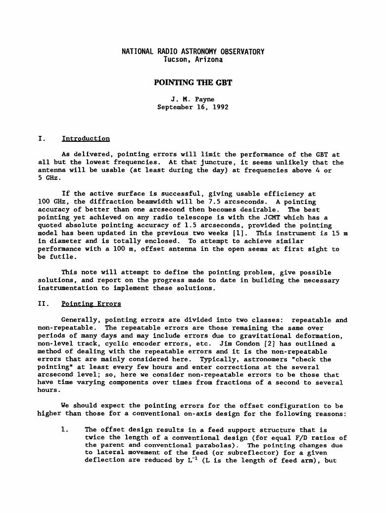
As delivered, pointing errors will limit the performance of the GBT at all but the lowest frequencies. At that juncture, it seems unlikely that the antenna will be usable (at least during the day) at frequencies above 4 or 5 GHz.
If the active surface is successful, giving usable efficiency at 100 GHz, the diffraction beamwidth will be 7.5 arcseconds. A pointing accuracy of better than one arcsecond then becomes desirable. The best pointing yet achieved on any radio telescope is with the JCMT which has a quoted absolute pointing accuracy of 1.5 arcseconds, provided the pointing model has been updated in the previous two weeks [1]. This instrument is 15 m in diameter and is totally enclosed. To attempt to achieve similar performance with a 100 m, offset antenna in the open seems at first sight to be futile.
This note will attempt to define the pointing problem, give possible solutions, and report on the progress made to date in building the necessary instrumentation to implement these solutions.
II. Pointing Errors
Generally, pointing errors are divided into two classes: repeatable and non-repeatable. The repeatable errors are those remaining the same over periods of many days and may include errors due to gravitational deformation, non-level track, cyclic encoder errors, etc. Jim Condon [2] has outlined a method of dealing with the repeatable errors and it is the non-repeatable errors that are mainly considered here. Typically, astronomers "check the pointing" at least every few hours and enter corrections at the several arcsecond level; so, here we consider non-repeatable errors to be those that have time varying components over times from fractions of a second to several hours.
We should expect the pointing errors for the offset configuration to be higher than those for a conventional on-axis design for the following reasons:
1. The offset design results in a feed support structure that is twice the length of a conventional design (for equal F/D ratios of the parent and conventional parabolas). The pointing changes due to lateral movement of the feed (or subreflector) for a given deflection are reduced by L"1 (L is the length of feed arm) , but

in general, the deflections of a loaded structure increase as a higher power of L. For a cantilevered beam, for example, the deflection at the end of the beam is proportional to L3, all other dimensions remaining equal. Of course, the feed legs of an on- axis antenna are not cantilevered and the GBT arm has a cross-section that is far greater than any on-axis system. In general, though, we would expect the repeatable pointing errors resulting from gravitational loading to be greater in the offset case. The following numbers illustrate this:
Zenith to Horizon
Deflection of Focal Point
Bonn 100m 150 mm
Calculated GBT 560 mm
Pointing Change
17.1 arcmin
31.5 arcmin
This is a pointing error that we expect to be highly repeatable, but any non-repeatable component will obviously be higher in the offset design than the conventional.
2. The offset design results in changes in pointing with focal length changes. This is not the case with a correctly aligned on-axis design. The calculated pointing change for axial movement of the subreflector is 2 arcseconds per mm for the GBT. The feed arm support is approximately 60 m in length, so a change in the temperature of the feed arm of 10C will give a pointing change of 2 arcseconds. Temperature differences between the feed arm and the rest of the structure may reach 5° or 10oC during the day, resulting in unpredictable pointing changes of 10 - 20 arcseconds. Of course, temperature differences between feed legs on an on-axis design also produce pointing changes but in a more complex way. Both lateral movement and tilt of the subreflector are involved.
3. The longer feed arm will result in poorer dynamic performance. The increased inertia results in lower resonant frequencies in the structure and, consequently, narrower servo bandwidths. The dynamic response of the feed arm to wind gusts and accelerations due to normal tracking and scanning is unknown at present, but may result in pointing jitter at some frequency around 1 Hz and inferior pointing performance in wind gusts. Almost certainly the performance when position switching will be inferior to an on-axis design due to longer settling time in both the servo and the structure.
The specified non-repeatable pointing error in the contract with RSI is 14 arcseconds. However, this pointing error does not include any significant thermal effects in the elevation support structure. During the day, these errors will likely be 10 - 20 arcseconds - perhaps more. This effect at the

100 m can be as high as 60 arcseconds during the day [3]. In fact, thermally induced deformations in the elevation support structure will probably be one of the major sources of pointing error. This has been true for both VIA and VLBA antennas.
The following table gives some sources of non-repeatable pointing error for daytime operation. These maximum values come from either RSI, rough calculation or educated guesses. Hopefully, in the next few months, a more complete analysis will yield more reliable values. For what follows, the accuracy of these numbers is not too important. They do illustrate, however, that early in the commissioning of the GBT, we must have instrumentation in place to drastically improve the pointing.
GBT Non-Reneatable Pointing Errors
^B^B2iP^!-* liP^^^ip::'.::; TIME SCALE
LIKELY MAX DAYTIME
VALUE INSTRUMENTATION FOR SENSING
Temperature differences in vertical supports of EL- axle
4 arcsec/0C Slow 30 arcsec Auto collimator/level/ rangefinder
Changes in main reflector —
Fast - Wind Slow - Thermal
10 arcsec ? "Floodlight" rangefinder. Steered beam rangefinder.
Lateral movement of subreflector
3 arcsec/mm Fast - Wind Slow - Thermal
15 arcsec Quadrant detector and/or rangefinders.
Axial movement of subreflector 2 arcsec/mm Slow - Thermal
20 arcsec (elevation only)
Rangefinder
These errors will obviously not occur simultaneously and some may cancel, but it seems inevitable that non-repeatable daytime pointing errors in the range of 20 - 30 arcseconds will be routine. The non-repeatable errors due to wind will also be present at night.
It is also worth noting that even on Mauna Kea anomalous refraction effects can produce pointing shifts of up to 10 arcseconds for periods of minutes at millimeter wavelengths [1].
[4]. James Lamb has produced a good review of thermal effects in antennas

III. Ins trumentation
Over the past two years, we have developed instrumentation that we believe to be adequate to sense the structural deformations causing the various pointing errors. At the start of the project, we elected to pursue two different approaches to solving the pointing problem. These are: the autocollimator pointing system and the laser rangefinder system. Both rely on the existence of a surface metrology system that continuously provides information on the direction of the axis of the parabola defined by the best fit to the measured surface points. Both systems also rely on instrumentation to measure the position of the subreflector with respect to the vertex of the main reflector.
The main reason for the parallel development of two systems is recognition that precision pointing is essential to the usefulness of the GBT. Also, at the start of the project, it was not clear that either system would give adequate performance. The intense experimental work of the past two years has revealed no fundamental reason why both systems will not work satisfactorily.
A. The Autocollimator System
The autocollimator system defines the position of the elevation axis in space to a precision of around one arcsecond with respect to a ground-based frame of reference.
A complete description of the proposed system is given by C. Brockway [5].
At the heart of the system is an instrument that has been developed and refined commercially over many years — the autocollimator. This instrument senses the tilt, in two orthogonal axes, of a plane reflecting mirror remote to the instrument. Measurement of tilt to an accuracy of a fraction of an arcsecond is routine with such instruments and electrical outputs proportional to the tilt in the two planes are available. NRAO has previous experience with autocollimators many years ago in work undertaken for the 65-m millimeter-wave telescope.
Figure 1 is a diagram of the proposed system. At the lowest level of the rotating telescope structure, directly beneath each elevation bearing, is a table stabilized with respect to gravity. Components are available to permit this stabilization to better than an arcsecond and the errors introduced by telescope motion should be negligible. On each of these tables, a dual axis autocollimator is mounted, its beam perpendicular to the table. At each end of the elevation axis, there is a two-axis reference platform allowing rotation in the x, z (tilt) planes and the y, z (elevation) plane. A mirror on the underside of the platform reflects the beam back to the autocollimator and a dual channel closed-loop servo system serves to maintain the platform normal to the autocollimator beam to a high degree of precision. It now is possible to measure the rotations of each end of the elevation support structure in the x, z and y, z planes with respect to gravity.
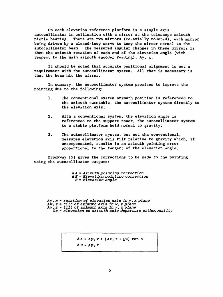
On each elevation reference platform is a single axis autocollimator in collimation with a mirror at the telescope azimuth pintle bearing. There are two mirrors (co-axially mounted), each mirror being driven by a closed-loop servo to keep the mirror normal to the autocollimator beam. The measured angular changes in these mirrors is then the azimuth rotation of each end of the elevation angle (with respect to the main azimuth encoder reading), Ay, x.
It should be noted that accurate positional alignment is not a requirement with the autocollimator system. All that is necessary is that the beam hit the mirror.
In summary, the autocollimator system promises to improve the pointing due to the following:
1. The conventional system azimuth position is referenced to the azimuth turntable, the autocollimator system directly to the elevation axis;
2. With a conventional system, the elevation angle is referenced to the support tower, the autocollimator system to a stable platform held normal to gravity;
3. The autocollimator system, but not the conventional, measures elevation axis tilt relative to gravity which, if uncompensated, results in an azimuth pointing error proportional to the tangent of the elevation angle.
Brockway [5] gives the corrections to be made to the pointing using the autocollimator outputs:
A A = Azimuth pointing correction LE = Elevation pointing correction
E = Elevation angle
Ay, x = rotation of elevation axle in y, x plane Ax, z = fciifc of azimuth axis in x, z plane Ay, z - tilt of azimuth axis in y, z plane
Qe = elevation to azimuth axis departure orthogonality
AA = Ay, x + {Ax, z + Qe) tan E A.E = Ay, z
For the proposed system to be successful, it is essential that atmospheric turbulence does not produce excessive angular errors in the output of the autocollimator. At the start of the project, it was recognized that propagation of the autocollimator beam through the open air over the path length required would probably result in excessive angular fluctuations and that although enclosure of the beam in a tube would reduce the fluctuations, it was not clear what improvement to expect.
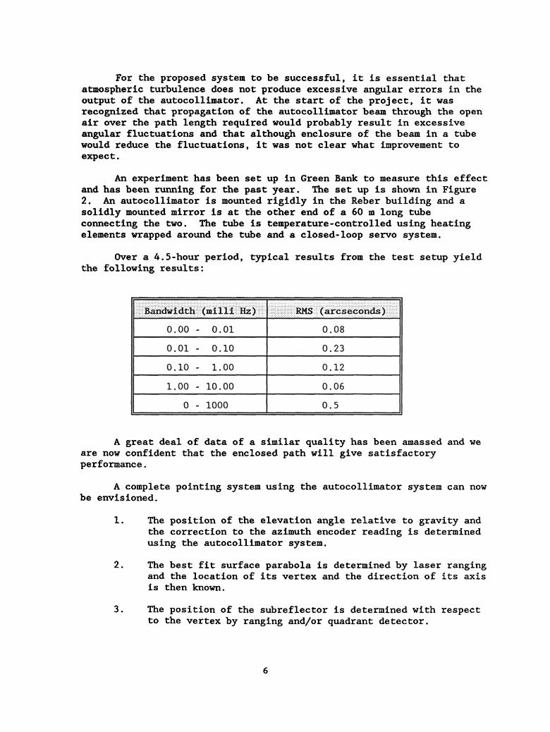
An experiment has been set up in Green Bank to measure this effect and has been running for the past year. The set up is shown in Figure 2. An autocollimator is mounted rigidly in the Reber building and a solidly mounted mirror is at the other end of a 60 m long tube connecting the two. The tube is temperature-controlled using heating elements wrapped around the tube and a closed-loop servo system.
Over a 4.5-hour period, typical results from the test setup yield the following results:
Bandwidth (milli Hz) RMS (arcseconds)
0.00 - 0.01 0.08
0.01 - 0.10 0.23
0.10 - 1.00 0.12
1.00 - 10.00 0.06
A great deal of data of a similar quality has been amassed and we are now confident that the enclosed path will give satisfactory performance.
A complete pointing system using the autocollimator system can now be envisioned.
1. The position of the elevation angle relative to gravity and the correction to the azimuth encoder reading is determined using the autocollimator system.
2. The best fit surface parabola is determined by laser ranging and the location of its vertex and the direction of its axis is then known.
3. The position of the subreflector is determined with respect to the vertex by ranging and/or quadrant detector.
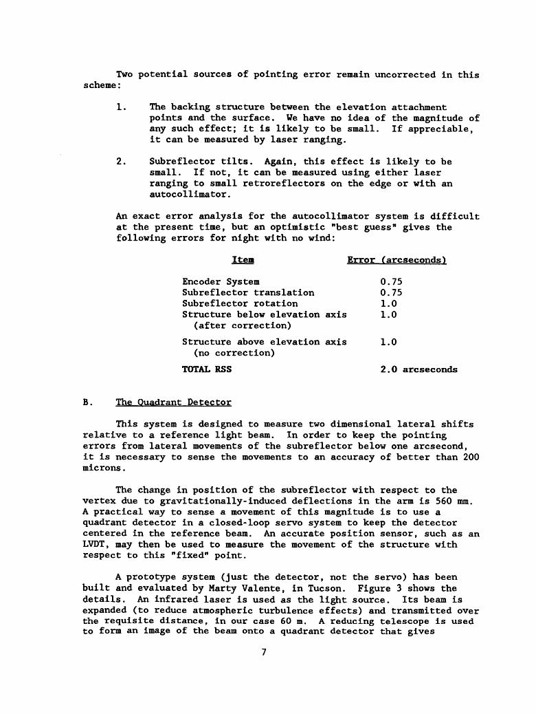
Two potential sources of pointing error remain uncorrected in this scheme:
1. The backing structure between the elevation attachment points and the surface. We have no idea of the magnitude of any such effect; it is likely to be small. If appreciable, it can be measured by laser ranging.
2. Subreflector tilts. Again, this effect is likely to be small. If not, it can be measured using either laser ranging to small retroreflectors on the edge or with an autocollimator.
An exact error analysis for the autocollimator system is difficult at the present time, but an optimistic "best guess" gives the following errors for night with no wind:
Item Error (arcseconds)
Encoder System 0.75 Subreflector translation 0.75 Subreflector rotation 1.0 Structure below elevation axis 1.0
(after correction)
Structure above elevation axis 1.0 (no correction)
TOTAL RSS 2.0 arcseconds
B. The Quadrant Detector
This system is designed to measure two dimensional lateral shifts relative to a reference light beam. In order to keep the pointing errors from lateral movements of the subreflector below one arcsecond, it is necessary to sense the movements to an accuracy of better than 200 microns.
The change in position of the subreflector with respect to the vertex due to gravitationally-induced deflections in the arm is 560 mm. A practical way to sense a movement of this magnitude is to use a quadrant detector in a closed-loop servo system to keep the detector centered in the reference beam. An accurate position sensor, such as an LVDT, may then be used to measure the movement of the structure with respect to this "fixed" point.
A prototype system (just the detector, not the servo) has been built and evaluated by Marty Valente, in Tucson. Figure 3 shows the details. An infrared laser is used as the light source. Its beam is expanded (to reduce atmospheric turbulence effects) and transmitted over the requisite distance, in our case 60 m. A reducing telescope is used to form an image of the beam onto a quadrant detector that gives

electrical outputs that are proportional to the displacement of the image from the center of the detector. To avoid effects due to ambient light changes, narrow band optical filtering is used and also the laser is modulated.
This system has been tested indoors at a range of 40 m in Green Bank with the results shown in Figure 4. The noise in a 10 Hz bandwidth was less than 10 microns. The system is now being installed at the top of a 50 m high tower in Green Bank, and we hope to have results shortly.
Of crucial importance is the stability of the laser mount. To achieve the required accuracy, the mount for the laser must have non- repeatable deflections of less than 1 arcsecond.
An alternative method is to use three laser rangefinders at the vertex to trilaterate on retroreflectors on the edge of the subreflector. Information on both tilt and lateral movement would then be available.
C. The Laser Rangefinder System
The laser rangefinder pointing system is a new idea for solving the pointing problem. The initial proposal for this kind of system is given in [6] and an error analysis of the surface metrology in [7]. Figure 5 gives this initial scheme, and an analysis of the resulting pointing accuracy by Fred Swab is shown in Figure 6. Over most of the sky, the pointing is better than one arcsecond. The limited areas where the pointing becomes worse is due to the structure obscuring the path from the ground-based rangefinders to the surface metrology rangefinders on the feed arm.
The basic requirement for a suitable ranging instrument is a capability of measuring distances of up to 120 m with an accuracy of better than 50 microns. A practical system also requires a fast measurement rate — five distances per second. At the start of the project, we were uncertain that such an instrument could be developed. We now have a completely developed system that satisfies these requirements. It is described in [8]. The instrument will be available in two forms: with and without the beam steering mirror. The component cost of the instrument with the beam steering is around $15,000.00. Without beam steering, it is around $8,000.00, probably $6,000.00 in quantity. At this price we can afford to be monitoring many distances on the structure continuously and referencing the structure to a "truss" of light beams becomes feasible. By referencing the position of the structure to fixed points on the ground, along with the surface metrology, the entire pointing problem can, in principle, be solved.
A different configuration that overcomes the blocking effects is shown in Figure 7. Around the edge of the main reflector are 12 retroreflector clusters. The precise location of any of these clusters with respect to the ground-based reference points may be determined continuously by observation with three (or more) of the ground-based
8

laser systems. Four clusters would be selected at a time, the selection depending on the telescope position. Each of the three surface metrology rangefinders may then determine its position with respect to three (or four, giving redundancy) of the clusters. This then connects the telescope coordinate system with the ground and the pointing problem is solved. A detailed analysis of this system has yet to be performed, but it should be superior to the previous configuration.
Additional aspects of the laser system are as follows:
1. Refractive index correction will not be necessary. The ground-based rangefinders measure between themselves and these measured lengths become the standard for the telescope metrology system. The effect of refractive index change with altitude on both the laser system and the incoming microwave radiation of interest remains to be evaluated.
2. The structure is so massive and the structural resonances so low in frequency that "feedforward" techniques may be used to predict in advance the position of measured points on the structure.
3. Any point on the structure may be selected for measurement. The placement of a retroreflector cluster at any point will enable that point to be monitored accurately from the ground at a high rate. When locked onto one target, the rangefinder can measure one hundred distances per second at 100 micron accuracy.
4. The rangefinders are relatively inexpensive. If any particular part of the structure turns out to affect the pointing adversely, then additional rangefinders may be simply added.
5. The original concept for the pointing system was to generate corrections. However, by calibrating each rangefinder on a fixed calibration range, absolute pointing becomes a possibility. Also, with some additional instrumentation, initial setting of the surface using the laser system becomes a possibility.
6. Although the initial plans call for measuring 2,000 points on the surface, it is likely that surface errors due to both wind and thermal effects will be correlated over large areas of the surface. It may be that sampling 100 points or even fewer may permit some degree of correction for surface deformations due to wind.
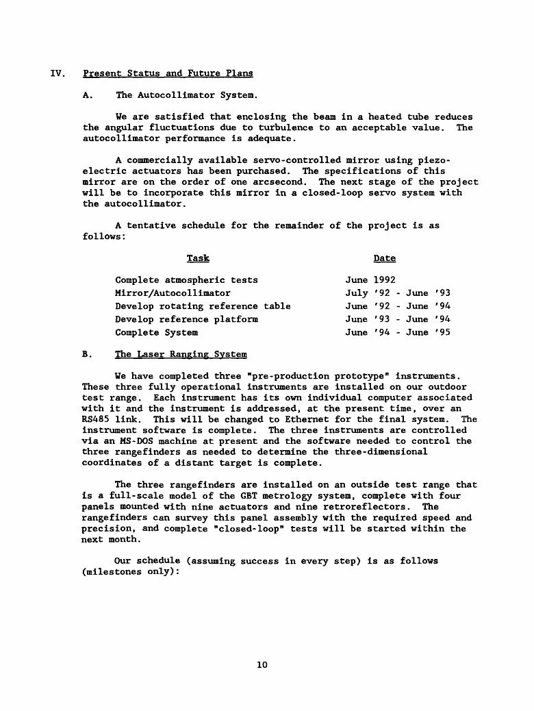
IV. Present Status and Future Plans
A. The Autocollimator System.
We are satisfied that enclosing the beam in a heated tube reduces the angular fluctuations due to turbulence to an acceptable value. The autocollimator performance is adequate.
A commercially available servo-controlled mirror using piezo¬ electric actuators has been purchased. The specifications of this mirror are on the order of one arcsecond. The next stage of the project will be to incorporate this mirror in a closed-loop servo system with the autocollimator.
A tentative schedule for the remainder of the project is as follows:
Task Date
Complete atmospheric tests June 1992 Mirror/Autocollimator July '92 - June '93 Develop rotating reference table June '92 - June '94 Develop reference platform June '93 - June '94 Complete System June '94 - June '95
B. The Laser Ranging System
We have completed three "pre-production prototype" instruments. These three fully operational instruments are installed on our outdoor test range. Each instrument has its own individual computer associated with it and the instrument is addressed, at the present time, over an RS485 link. This will be changed to Ethernet for the final system. The instrument software is complete. The three instruments are controlled via an MS-DOS machine at present and the software needed to control the three rangefinders as needed to determine the three-dimensional coordinates of a distant target Is complete.
The three rangefinders are installed on an outside test range that is a full-scale model of the GBT metrology system, complete with four panels mounted with nine actuators and nine retroreflectors. The rangefinders can survey this panel assembly with the required speed and precision, and complete "closed-loop" tests will be started within the next month.
Our schedule (assuming success in every step) is as follows (milestones only):
10

Sept. '92 Nov. '92 Nov. '92 Feb. '93 June '93 Sept. '92 - ? June '93 -Sept.
Task Completion Date
Demonstration of complete system model Set up absolute distance range
Design of production rangefinder Completion of first article Build 8 rangefinders Develop pointing software Install pointing system on June '93 -Sept. '93
test telescope Build 10(?) rangefinders July '93 - July '94
We feel that it is important to keep up the flow of development, both in hardware and software, in spite of the fact that the telescope will not be available until 1995. One way to do this is to force the pace with experiments simulating the final application. The first of these is the panel experiment, a complete simulation of a section of the surface of the GBT with the metrology system. The second experiment could be the installation of a pointing system using the rangefinders (perhaps in a limited way) on a test telescope, either the 140-foot or a VLBA antenna. With each experiment we debug the system and end up with hardware and software useable on the GBT.
A system aimed at the measurement of the surface at a high rate (faster than once per second) is being investigated. This is shown in Figure 8. A high power (1W) laser illuminates the entire surface with light modulated at 1.5 GHz. The returned light from the 2,000 retroreflectors passes through a modulator running at a frequency differing from the laser modulation frequency by a few tens of Hertz. The image of the entire surface is then formed onto a CCD. The phase difference between the amplitude modulated images of the surface retroreflectors is a measure of the distance differences to the retroreflectors. Preliminary calculations on signal-to-noise ratios and computing capacity indicate that such a system is feasible.
Our intention is to proceed with the single beam instrument and to pursue this far more ambitious instrument at a low level of effort.
V. Implementation
As a basis for discussion, a block diagram of a basic implementation is given in Figure 9. The various boxes can be separate processors or all part of one machine.
1. Active Surface/Pointing/Control System Interface — This is a processor that performs the coordination and communication between the active surface/pointing processes and the control system.
2. Actuator Control — This is the Transition Technology system that accepts commands to position each of the more than 2,000 actuators.
3. Position Command Processor — In the open-loop case, the position commands output from this processor are derived from a look-up
11
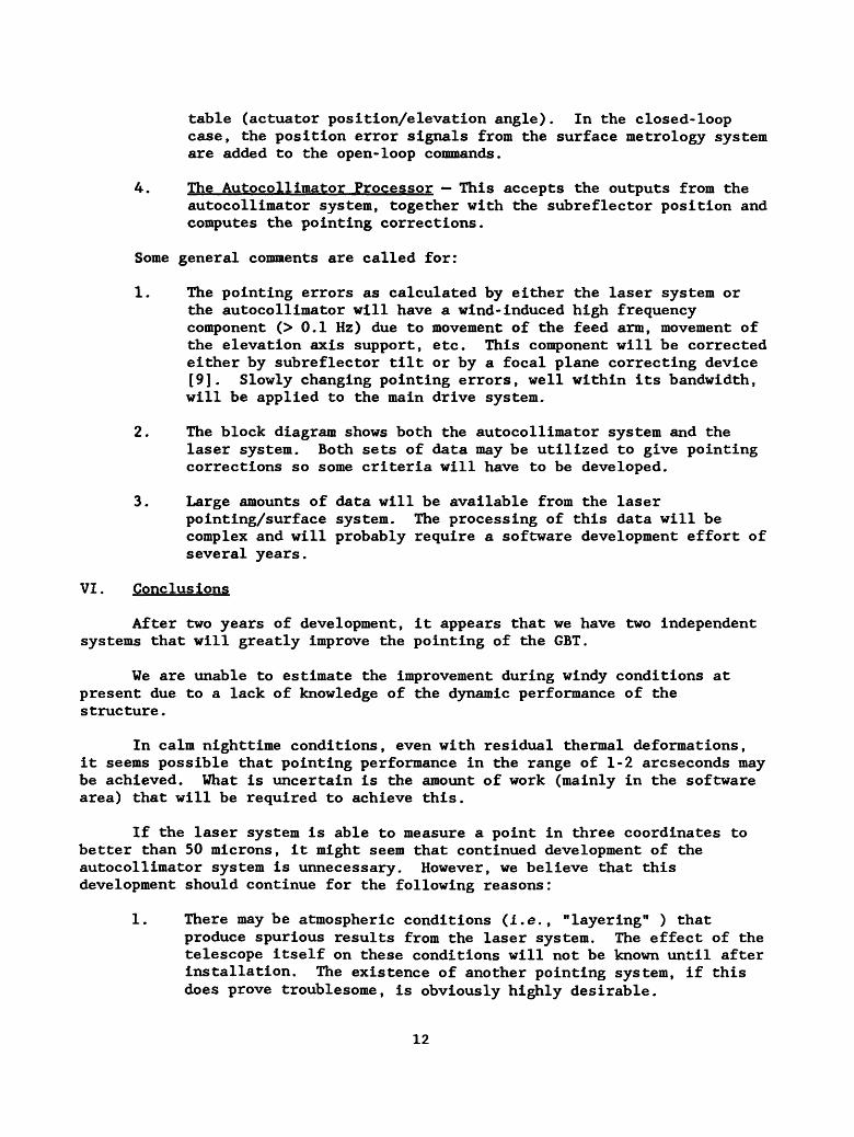
table (actuator position/elevation angle). In the closed-loop case, the position error signals from the surface metrology system are added to the open-loop commands.
4. The Autocollimator Processor — This accepts the outputs from the autocollimator system, together with the subreflector position and computes the pointing corrections.
Some general comments are called for:
1. The pointing errors as calculated by either the laser system or the autocollimator will have a wind-induced high frequency component (> 0.1 Hz) due to movement of the feed arm, movement of the elevation axis support, etc. This component will be corrected either by subreflector tilt or by a focal plane correcting device [9]. Slowly changing pointing errors, well within its bandwidth, will be applied to the main drive system.
2. The block diagram shows both the autocollimator system and the laser system. Both sets of data may be utilized to give pointing corrections so some criteria will have to be developed.
3. Large amounts of data will be available from the laser pointing/surface system. The processing of this data will be complex and will probably require a software development effort of several years.
VI. Conclusions
After two years of development, it appears that we have two independent systems that will greatly improve the pointing of the GBT.
We are unable to estimate the improvement during windy conditions at present due to a lack of knowledge of the dynamic performance of the structure.
In calm nighttime conditions, even with residual thermal deformations, it seems possible that pointing performance in the range of 1-2 arcseconds may be achieved. What is uncertain is the amount of work (mainly in the software area) that will be required to achieve this.
If the laser system is able to measure a point in three coordinates to better than 50 microns, it might seem that continued development of the autocollimator system is unnecessary. However, we believe that this development should continue for the following reasons:
1. There may be atmospheric conditions (i.e., "layering" ) that produce spurious results from the laser system. The effect of the telescope itself on these conditions will not be known until after installation. The existence of another pointing system, if this does prove troublesome, is obviously highly desirable.
12

2. Certain atmospheric conditions may render the laser system useless. Heavy rain, fog, or icing conditions may degrade the performance of the laser system. The autocollimator, with light beams enclosed in tubes, will be invulnerable to weather. Although such weather conditions will preclude millimeter wavelength operations, observation at lower frequencies, where pointing corrections are still needed, may be possible.
3. The pointing performance of the GBT is such a crucial issue that it is only common sense to have two independent systems.
JMP/nlc
13

REFERENCES
[1]. Richard Hills — private communication.
[2]. GBT Memo #75 - GBT Pointing Equations; J. Condon.
[3]. Johann Schraml, Jaap Baars — Private communication.
[4]. James Lamb, MMA Memo No. 83, May 5, 1992.
[5]. GBT Memo #38 - GBT Fine Pointing; Chuck Brockway.
[6]. GBT Memo #36 — Pointing and surface control of GBT; John Payne.
[7]. GBT Memo #37 - Error Sensitivity of GBT Laser Metrology; F. Schwab
[8]. GBT Memo #73 - A Rangefinder with Fast Multiple Range Capability; J. Payne, D. Parker, R. Bradley.
[9]. GBT Pointing Memorandum - J. Payne; 1/28/92.
14

GBT-FINE POINTING CORRECTION SYSTEM
AUTOCOLUMATOR
ELEVATION REFERENCE PLATFORM STABLE IN X-Y
TWO AXIS LIGHT BEAM IN TUBE
AUTOCOLUMATOR ON PLATFORM MIRROR ROTATES
WITH AZMUTH-SERVOED TO AUTO COLUMATOR ON REFERENCE PLATFORM
PUTFORM STABILIZED W.R.T. GRAVITY STABLE IN X-Y PLANE
FIGURE 1

Pointing Error (arc sec)
40
Elevation
Azimuth
FIGURE 6

Three Rangefinders
12 Retroreflector Clusters around edge of Reflector
n
12 Ground Base Rangefinders (in a circle around telescope)
n n
n
FIGURE 7
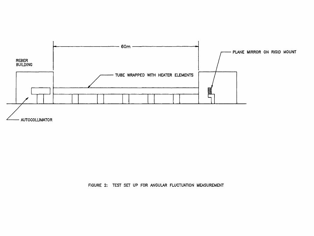
REBER BUILDING
60m
/
TUBE WRAPPED WITH HEATER ELEMENTS
PLANE MIRROR ON RIGID MOUNT
AUTOCOLLIMATOR
FIGURE 2: TEST SET UP FOR ANGULAR FLUCTUATION MEASUREMENT

ELECTRONICS
DRIVE SIGNALS
SERVO CONTROLLED X 8c Y TRANSLATION STAGES
LASER/EXPANDER ASSEMBLY
il X-Y ERROR SIGNALS
LOCATION CLOSE TO SUBREFLECTOR
REDUCER/DETECTOR ASSEMBLY
60m
A VERTEX
FIGURE 3: DIAGRAM OF DETECTOR

VOLTS o
0 i
7 1 6 1 t
, ♦ 5 4 T
' . t 4 1 T
4 3 . t
1 T 2 i
< \
i ( > i i \
0 i i
( ) 1 ( 1
—i ( >
-2 ( I
[ \
-3 ( \ \
( ►
-4 ( >
( <
1 )
-5 ( >
I { \
-6 ( I
( ► ( t
-7 }
-8 .
INCHES
FIGURE 4: QUADRANT DETECTOR RESPONSE
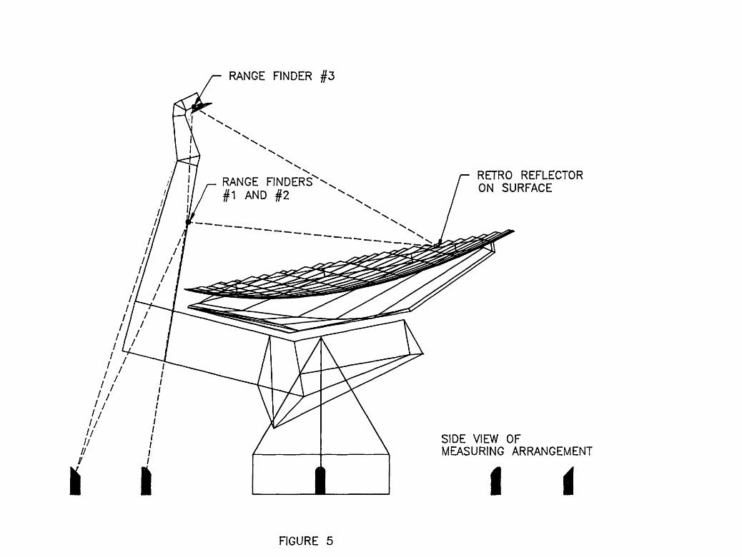
RANGE FINDER #3
RETRO REFLECTOR ON SURFACE
SIDE VIEW OF MEASURING ARRANGEMENT
I FIGURE 5

CCD IMAGE
RETROREFLECTORS ON SURFACE
71
MODULATOR
CCD
FIG 8: "FLOODLIGHT METHOD

2000 LVDT INPUTS
2000 MOTOR DRIVES
ACTUATOR CONTROL
SURFACE INTERFACE
2000 POSITION
COMMANDS
LVDT READINGS
MOTOR CURRENTS
POSITION COMMAND PROCESSOR
ELEVATION ANGLE
T LOOK-UP TABLE UPDATE
2000 POSITION
ERROR SIGNALS
CLOSED LOOP/ OPEN LOOP
ACTIVE SURFACE/ POINTING/ CONTROL SYSTEM INTERFACE/
PROCESSOR
SUBRERECTOR POSITION
POINTING CORRECTIONS
AUTO COLUMATOR PROCESSOR
AUTO COLLIMATOR
SYSTEM
SURFACE METROLOGY PROCESSOR
ABSOLUTE POINTING
_L
BEST FIT AXIS
— OUTPUT COMMANDS TO 3-6 RANGEFINDERS — RANGE INFORMATION — FEED ARM TEMPERATURES — FEED ARM POSITION
REFRACTIVE INDEX (SCAUNG)
LASER POINTING
PROCESSOR
AZ POSITION
EL POSITION
— OUTPUTS TO 12-20 RANGEFINDERS — INPUTS FROM 12-20 RANGEFINDERS — SUBREFLECTOR QUADRANT DETECTOR
— SLOW CORRECTION TO TELESCOPE SERVO
— FAST CORRECTION TO SUBREFLECTOR OR FOCAL PLANE MIRROR
— ETHERNET TO CONTROL SYSTEM
FIG 9: BLOCK DIAGRAM - POINTING AND ACTIVE SURFACE