18 Indeterminate Beam
15
Indeterminate beams Prof Schierle 1 Indeterminate beams
Transcript of 18 Indeterminate Beam

Indeterminate beams Prof Schierle 1
Indeterminatebeams

Indeterminate beams Prof Schierle 2
Indeterminate beams1 Simple beam (determinate)2 Fixed end beam (indeterminate)
M = WL/24 (mid-span)M = -WL/12 (supports)
3 Continuous beam (2-bays)4 Continuous beam (3-bays)Indeterminate beams cannot be analyzed by static analysis. However, bending coefficients are available forcommon conditions, such as beams withuniform load or equally spaced point loads,and supported by equally spaced supports.Using coefficients, bending moments are:
M = C W LM = bending momentC = CoefficientW = w L (total load)L = span between supports

Indeterminate beams Prof Schierle 3
Fixed end beamsUsually have moment resistantConnections to columns
Fixed ends create negativebending at the supports thatreduces the positive bendingbetween supports
The combined bending is equalto that of an equivalent simple beam but the separate smaller bendingmoments allow smaller beams

Indeterminate beams Prof Schierle 4
Bending coefficients for fixed end beam \ExamplesAssume: L = 30’, W = 60 k = 2klf x 30’
1 Fixed end beam with uniform loadM = -.083 (60) 30 M = -149 k’ M = .042 (60) 30 M = 76 k’
2 Fixed end beam with 1 point loadM = -.125 (60) 30 M = -225 k’ M = .125 (60) 30 M = 225 k’
3 Fixed end beam with 2 point loadsM = -.111 (60) 30 M = -200 k’ M = .056 (60) 30 M = 101 k’
4 Fixed end beam with 3 point loadsM = -.104 (60) 30 M = -187 k’ M = .063 (60) 30 M = 113 k’

Indeterminate beams Prof Schierle 5
Bending coefficients for continuous beams
Since dead load (DL) is always applied butlive load (LL) may or may not be applied:• Beams at left are fully loaded with DL• Beams at right have LL on all or alternate
bays, whichever gives the greatest results
Dead load Live load

Indeterminate beams Prof Schierle 6
Dead load Live load Dead Load CoefficientsAssume:L = 30’, W = 60k / bay (W = w L) 1 Beam with uniform DL
2-bay beamBay M = .070 (60) 30 M = 126 k’Support M = -.125 (60) 30 M = -225 k’3-bay beam End bay M = .080 (60) 30 M = 144 k’Mid bay M = .025 (60) 30 M = 45 k’Support M = -.100 (60) 30 M = -180 k’
2 Beam with 1 point DL per bay3-bay beamEnd bay M = .175 (60) 30 M = 315 k’Mid bay M = .100 (60) 30 M = 180 k’Support M = -.150 (60) 30 M = -270 k’
3 Beam with 2 point DL per bay3-bay beamEnd bay M = .122 (60) 30 M = 220 k’Mid bay M = .033 (60) 30 M = 59 k’Support M = -.134 (60) 30 M = -241 k’

Indeterminate beams Prof Schierle 7
Dead load Live load Live Load CoefficientsAssume:L = 30’, W = 60k / bay (W = w L) 4 Beam with uniform LL
2-bay beamBay M = .096 (60) 30 M = 173 k’Support M = -.125 (60) 30 M = -225 k’3-bay beam End bay M = .101 (60) 30 M = 182 k’Mid bay M = .075 (60) 30 M = 135 k’Support M = -.117 (60) 30 M = -211 k’
5 Beam with 1 point LL per bay3-bay beamEnd bay M = .213 (60) 30 M = 383 k’Mid bay M = .175 (60) 30 M = 315 k’Support M = -.175 (60) 30 M = -315 k’
6 Beam with 2 point LL per bay3-bay beamEnd bay M = .144 (60) 30 M = 259 k’Mid bay M = .100 (60) 30 M = 180 k’Support M = -.156 (60) 30 M = -281 k’
Indeterminate beams Prof Schierle 8
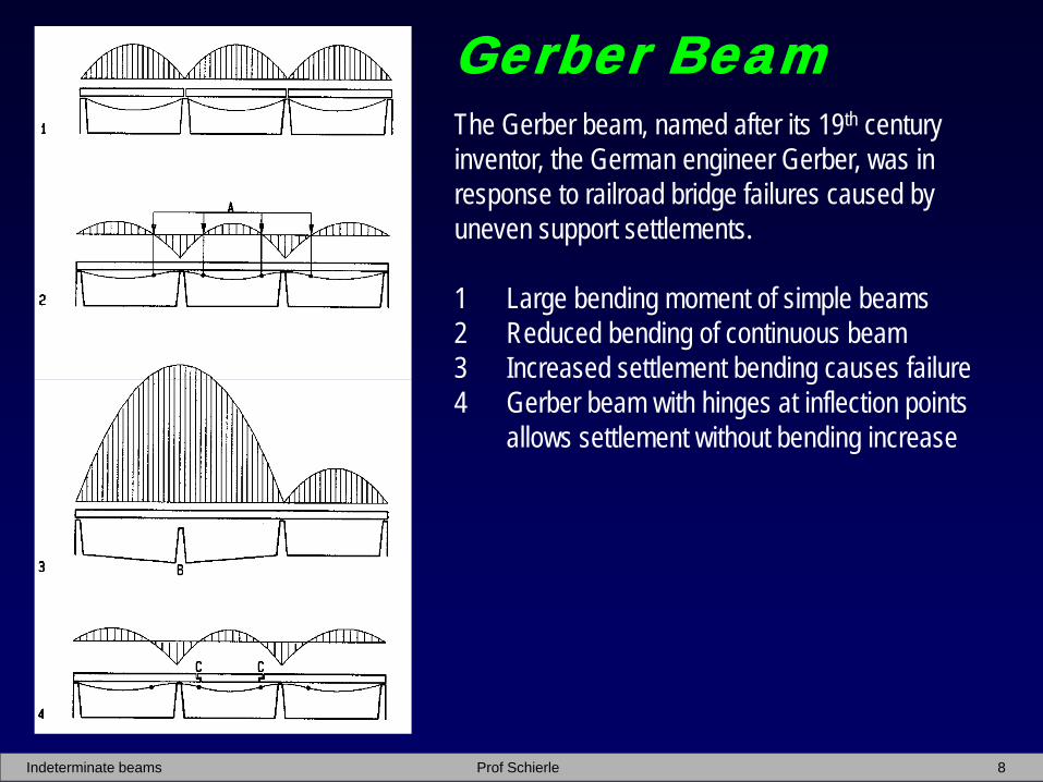
Gerber BeamThe Gerber beam, named after its 19th centuryinventor, the German engineer Gerber, was inresponse to railroad bridge failures caused byuneven support settlements.
1 Large bending moment of simple beams2 Reduced bending of continuous beam3 Increased settlement bending causes failure4 Gerber beam with hinges at inflection points
allows settlement without bending increase

Indeterminate beams Prof Schierle 9
Gerber beams are used for glue-lamwarehouse roof beams to reducebending moments and beam size
Hinge detail

Indeterminate beams Prof Schierle 10
Beam diagrams• Typical V M diagrams without computing • Visualize deflection as a flexible ruler• Draw shear and bending diagrams left to right;
starting and ending with zero beyond the beam• Uniform load cause downward sloping shear• Point loads cause downward shear offset• Upward reactions cause upward shear offset• Estimate shear area to draw bending diagrams1 Cantilever beam with point load2 Cantilever beam with uniform load3 Cantilever beam with mixed load4 Simple beam with point loads5 Simple beam with uniform load6 Simple beam with mixed load7 Beam with 1 overhang and point load8 Beam with 1 overhang and uniform load9 Beam with 1 overhang and mixed load10 Beam with 2 overhangs and point loads11 Beam with 2 overhangs and uniform load12 Beam with 2 overhangs and mixed load

Indeterminate beams Prof Schierle 11
Shear effect
1 Beam with square mark to study stress 2 Shear stress on square3 Equivalent split shear stress4 Shear stress as tension/compression stress5 Equivalent tension/compression stress
cause diagonal tension cracks at beam supports
Isostatic lines combine bending and shear stress(compressive ”arch” lines and tensile “cable” lines)

Indeterminate beams Prof Schierle 12
Shear and bending distribution
1 Beam diagram
2 Shear diagram
3 Bending diagram
4 Shear stress
5 Bending stress
A Best location of possible pipe hole:• Zero shear force at mid-span• Zero bending stress at mid-depth
The diagrams reveal an interesting paradox:
• Linear shear force over beam length• Parabolic shear stress over beam depth• Parabolic bending moment over beam length• Linear bending stress over beam depth

Indeterminate beams Prof Schierle 13
Girder optimization1 Stepped bending diagram used to optimize:
44
5
6
2 Steel girder with plates welded outside flanges
3 Steel girder with plates welded inside flanges
4 Concrete girder with rebar lengths as required
5 Parabolic girder reflecting bending moment
6 Tapered girder approximates bending moment

Indeterminate beams Prof Schierle 14
Overhang effect
1 Simple beam
2 Beam overhangs reduce bending moment
~1/3 overhangs equalize positive and negative bending
Overhangs can provide synergy with architectural design
Overhangs reduce bending up to ~ 600%

Indeterminate beams Prof Schierle 15
happy end