1785-6.5.1, Data Highway/Data Highway Plus … Data Highway/Data Highway Plus Communication Adapter...
65
Preface Data Highway/Data Highway Plus Communication Adapter Module (Cat. No. 1785–KA) User’s Manual
Transcript of 1785-6.5.1, Data Highway/Data Highway Plus … Data Highway/Data Highway Plus Communication Adapter...

Preface
Data Highway/Data Highway PlusCommunication Adapter Module
(Cat. No. 1785–KA)
User’s Manual
Preface
Because of the variety of uses for this equipment and because of thedifferences between this solid state equipment and electromechanicalequipment, the user of and those responsible for applying this equipmentmust satisfy themselves as to the acceptability of each application and useof the equipment. In no event will Allen-Bradley Company be responsibleor liable for indirect or consequential damages resulting from the use orapplication of this equipment.
The illustrations, charts, and layout examples shown in this manual areintended solely to illustrate the text of this manual. Because of the manyvariables and requirements associated with any particular installation,Allen-Bradley Company cannot assume responsibility or liability for actualuse based upon the illustrative uses and applications.
No patent liability is assumed by Allen-Bradley Company with respect touse of information, circuits, equipment or software described in this text.
Reproduction of the contents of this manual, in whole or in part, withoutwritten permission of the Allen-Bradley Company is prohibited.
1988 Allen-Bradley Company. Inc.
PLC is a registered trademark of Allen-Bradley Company, Inc.
Important User Information

Using This Manual 3. . . . . . . . . . . . . . . . . . . . . . . . . . . . . . .
Chapter Objectives 3. . . . . . . . . . . . . . . . . . . . . . . . . . . . . . . . . . .
Purpose of This Manual 3. . . . . . . . . . . . . . . . . . . . . . . . . . . . . . .
Who Should Read This Manual 3. . . . . . . . . . . . . . . . . . . . . . . . . .
What This Manual Contains 4. . . . . . . . . . . . . . . . . . . . . . . . . . . .
Precautionary Notes 5. . . . . . . . . . . . . . . . . . . . . . . . . . . . . . . . . .
Frequently Used Terms 5. . . . . . . . . . . . . . . . . . . . . . . . . . . . . . .
Related Products 6. . . . . . . . . . . . . . . . . . . . . . . . . . . . . . . . . . . .
Related Publications 7. . . . . . . . . . . . . . . . . . . . . . . . . . . . . . . . . .
In the Next Chapter 8. . . . . . . . . . . . . . . . . . . . . . . . . . . . . . . . . .
Overview of the 1785�KA Module 1. . . . . . . . . . . . . . . . . . . .
Chapter Objectives 1. . . . . . . . . . . . . . . . . . . . . . . . . . . . . . . . . . .
What is the 1785�KA Module 1. . . . . . . . . . . . . . . . . . . . . . . . . . . .
What are the Data Highway and Data Highway Plus Networks? 2. . .
Data Highway 4. . . . . . . . . . . . . . . . . . . . . . . . . . . . . . . . . . . .
Data Highway Plus 4. . . . . . . . . . . . . . . . . . . . . . . . . . . . . . . . .
In the Next Chapter 4. . . . . . . . . . . . . . . . . . . . . . . . . . . . . . . . . .
Installing the 1785�KA Module 1. . . . . . . . . . . . . . . . . . . . . .
Chapter Objectives 1. . . . . . . . . . . . . . . . . . . . . . . . . . . . . . . . . . .
Setting the Communication Option Switches 1. . . . . . . . . . . . . . . . .
Switch Assembly SW�1: Network Link Communication Rate 2. . . .
Switch Assembly SW�2 and SW�3: For Future Use 3. . . . . . . . . .
Switch Assemblies SW�4, SW�5, and SW�6:Data Highway and Data Highway Plus Node Addresses 3. . . .
Mounting the 1785�KA Module 6. . . . . . . . . . . . . . . . . . . . . . . . . .
Making Connections to the 1785�KA Module 7. . . . . . . . . . . . . . . . .
Powering Up the 1785�KA Module 9. . . . . . . . . . . . . . . . . . . . . . . .
In the Next Chapter 9. . . . . . . . . . . . . . . . . . . . . . . . . . . . . . . . . .
Communicating Through the 1785�KA Module 1. . . . . . . . . .
Chapter Objectives 1. . . . . . . . . . . . . . . . . . . . . . . . . . . . . . . . . . .
Communicating From Data Highway to Data Highway Plus 1. . . . . .
Communicating from a PLC�2 on Data Highway to a PLC�5 on Data Highway Plus 2. . . . . . . . . . . . . . . . . . . . . . . . . . . . . .
How to Address a PLC�5 From a PLC�2 3. . . . . . . . . . . . . . . . . .
Communicating from a PLC�3 on Data Highway to a PLC�5 on Data Highway Plus 5. . . . . . . . . . . . . . . . . . . . . . . . . . . . . .
Addressing a PLC�5 From a PLC�3 6. . . . . . . . . . . . . . . . . . . . .
Table of Contents

Table of Contentsii
Communicating from a Computer on Data Highway to a PLC�5 on Data Highway Plus 7. . . . . . . . . . . . . . . . . . . . . . . . . . . . . .
Communicating From Data Highway Plus to Data Highway 9. . . . . .
How to Use the PLC�5 Message Instruction 10. . . . . . . . . . . . . . . . .
Monitoring and Modifying the Message Instruction 12. . . . . . . . . . . .
In the Next Chapter 13. . . . . . . . . . . . . . . . . . . . . . . . . . . . . . . . . .
1785�KA LED Indicators and Diagnostic Counters 1. . . . . . .
Chapter Objectives 1. . . . . . . . . . . . . . . . . . . . . . . . . . . . . . . . . . .
Using the LED Indicators 1. . . . . . . . . . . . . . . . . . . . . . . . . . . . . .
How to Use the 1785�KA Diagnostic Counters 3. . . . . . . . . . . . . . .
What is a Diagnostic Counter? 3. . . . . . . . . . . . . . . . . . . . . . . .
How to Read Diagnostic Counters 4. . . . . . . . . . . . . . . . . . . . . . . .
1785�KA Diagnostic Counters 5. . . . . . . . . . . . . . . . . . . . . . . . . . .
Data Highway Diagnostic Counters 5. . . . . . . . . . . . . . . . . . . . .
Data Highway Plus Diagnostic Counters 6. . . . . . . . . . . . . . . . . . . .
In the Following Appendices 6. . . . . . . . . . . . . . . . . . . . . . . . . . . .
Specifications 1. . . . . . . . . . . . . . . . . . . . . . . . . . . . . . . . . .
Examples of Communicating Between Data Highway and Data Highway Plus 1. . . . . . . . . . . . . . . . . . . . . . . .
Appendix Objectives 1. . . . . . . . . . . . . . . . . . . . . . . . . . . . . . . . . .
Data Highway/Data Highway Plus Example Network Configuration 2.
Example 1: PLC�2 (DH) to PLC�5 (DH +) 3. . . . . . . . . . . . . . . . . . .
PLC�2 Program Example 4. . . . . . . . . . . . . . . . . . . . . . . . . . . .
Example 2: PLC�3 (DH) to PLC�5 (DH +) 6. . . . . . . . . . . . . . . . . . .
PLC�3 Program Example 7. . . . . . . . . . . . . . . . . . . . . . . . . . . .
Example 3: Computer (DH) to PLC�5 (DH +) 11. . . . . . . . . . . . . . . . .
PLC�2 Normal Unprotected Write 12. . . . . . . . . . . . . . . . . . . . . . .
PLC�2 Normal Unprotected Read 13. . . . . . . . . . . . . . . . . . . . . .
PLC�3 Normal Unprotected Write (Word Range Write) 14. . . . . . . .
PLC�3 Normal Unprotected Read (Word Range Read) 15. . . . . . .
Example 4: PLC�5 (DH +) to PLC�2 (DH) 16. . . . . . . . . . . . . . . . . . .
PLC�2 Write Commands 16. . . . . . . . . . . . . . . . . . . . . . . . . . . . .
PLC�2 Read Commands 17. . . . . . . . . . . . . . . . . . . . . . . . . . . . .
Program Verification 17. . . . . . . . . . . . . . . . . . . . . . . . . . . . . . . .
Example 5: PLC�5 (DH +) to PLC�3 (DH) 18. . . . . . . . . . . . . . . . . . .
PLC�3 Write Commands 18. . . . . . . . . . . . . . . . . . . . . . . . . . . . .
PLC�3 Read Commands 19. . . . . . . . . . . . . . . . . . . . . . . . . . . . .
Program Verification 19. . . . . . . . . . . . . . . . . . . . . . . . . . . . . . . .
Example 6: PLC�5 (DH +) to PLC�5 (DH +) 20. . . . . . . . . . . . . . . . . .
PLC�3 Read Commands 20. . . . . . . . . . . . . . . . . . . . . . . . . . . . .
PLC�5 Write Commands 21. . . . . . . . . . . . . . . . . . . . . . . . . . . . .
Program Verification 21. . . . . . . . . . . . . . . . . . . . . . . . . . . . . . . .
Chapter 1
Using This Manual
After reading this chapter, you should know:
if this manual contains the information you needwhere to locate information in this manualwhere to locate information on related products
This manual describes the 1785-KA PLC-5 Data Highway/Data HighwayPlus Communication Adapter Module. It gives you information for:
installing the 1785-KAtroubleshooting the 1785-KA
You should read this manualbefore attempting to install or use the1785-KA. We assume that you are already familiar with:
Allen-Bradley Programmable Logic Controllers (PLCs)Allen-Bradley Data Highway and Data Highway Plus
Chapter Objectives
Purpose of This Manual
Who Should Read ThisManual

Using This ManualChapter 1
1–4
This manual contains five chapters and two appendices:
Chapter/Appendix: Title: Contains:
1 Using This Manual information you need to know for using thismanual properly
2 Overview of the 1785�KA conceptual information to help youunderstand the operation of the 1785�KA.Data Highway, and Data Highway Plus
Installing the 1785�KA Module procedures for:
� setting switches
� mounting the module
� connecting the module to Data HighwayPlus
� connecting the module to Data Highway
� powering up the module
4 Communicating Through the1785�KA Module
guidelines for using your 1785�KA tocommunicate between nodes on your DataHighway Plus and Data Highway networks.
5 1785�KA LED Indicators andDiagnostic Counters
descriptions of the 1785�KA LEDs anddiagnostic counters
A Specifications 1785�KA specifications
B Examples of CommunicatingBetween Data Highway andData Highway Plus
examples of how to communicate betweenData Highway and Data Highway Plus usingthe 1785�KA
What This Manual Contains

Using This ManualChapter 1
1–5
In this manual, you will see:
warnings that indicate where you may be injured if you do not followprocedures properly
cautions that indicate where equipment may be damaged if you do notfollow procedures properly
important notes that stress information that is critical to yourunderstanding and use of the product
In this manual, we use the following terms:
This Term: Means:
Data Highway Plus formerly the Peer Communications Link (PCL)
DH Data Highway
DH+ Data Highway Plus
node interface point at which devices, such asprogrammable controllers, connect to the network.Usually, the node is an interface module. except forthe PLC�5 and T50 terminal which connect directlyto Data Highway Plus.
In some Allen�Bradley documentation, you may findthe term station used in place of the term node.
PLC Programmable Logic Controller; generic term forany of Allen�Bradley's PLC product lines (such asPLC�2, PLC�3, etc...)
Precautionary Notes
Frequently Used Terms

Using This ManualChapter 1
1–6
Allen-Bradley offers a wide range of interfaces and software for DataHighway and Data Highway Plus networks, including:
Product:CatalogNumber:
Data Highway Communication Adapter Module 1771�KA2
Data Highway Interface Module for PROVOXInstrumentation System
1771�KX1
Data Highway Communication Controller Module 1771�KE,�KF
Data Highway PLC�4 Communication Interface 1773�KAA,�KAB
Data Highway PLC�3 Communication AdapterModule
1775�KA
PLC�3 Family I/O Scanner Communication AdapterModule
1775�S5,�SR5
Data Highway Plus Communication Adapter Module 1775�S5, SR5
Data Highway/Data Highway Plus CommunicationInterface Module
1770�KF2
PLC�5 Programming Software 6200�PLC5
Industrial Terminal System 1784�T50
6001�NET Data Highway Communications Software Series 6001
Data Highway Diagnostic Software 6001�F3E
Related Products

Using This ManualChapter 1
1–7
For more information on DataHighway and Data Highway Plus networks,refer to:
Publication:PublicationNumber:
Data Highway Cable Assembly and InstallationManual
1770�6.2.1
Data Highway/Data Highway Plus Protocol andCommand Set Reference Manual
1770�6.5.16
Data Highway PLC�2 (1771�KA2) CommunicationAdapter Module User's Manual
1771�6.5.1
Data Highway/RS�232�C (1771�KE,�KF)Communication Controller Module User's Manual
1771�6.5.15
Data Highway PLC�4 (1773�KAA,�KAB)Communication Interface User's Manual
1773�6.5.2
Data Highway PLC�3 (1775�KA) CommunicationAdapter Module User's Manual
1775�6.5.1
PLC�3 Family I/O Scanner (1775�S5,�SR5)Communication Adapter Module
1775�6.5.5
Data Highway Plus/RS�232�C (1785�KE)Communication Interface Module User's Manual
1785�6.5.2
Data Highway/Data Highway Plus (1770�KF2)Communication Interface Module User's Manual
1770�6.5.13 3
PLC�5 Programming Software User's Manual 6200� 6.5.5
Industrial Terminal System (T50) User's Manual 1784�6.5.1
6001�NET (VMS) Data Highway CommunicationSoftware User's Manual
6001�6.5.1
6001�NET (RSX�11) Data Highway CommunicationSoftware User's Manual
6001�6.5.2
Data Highway Diagnostic Software (6001�F3E)User's Manual
6001�6.5.3
The publications in the previous table are available from Allen-Bradley.Contact your local Allen-Bradley sales office for more information.
Related Publications

Using This ManualChapter 1
1–8
In Chapter 2, we give you an overview of how to use the 1785-KA withData Highway and Data Highway Plus.
In the Next Chapter

Chapter 2
Overview of the 1785�KA Module
In this chapter, we give you an overview of the 1785-KA module and howit interfaces with Data Highway and Data Highway Plus networks.
The 1785-KA module is a communication adapter that connects a DataHighway Plus network (including PLC-5 family controllers) to nodes onan Allen-Bradley Data Highway.
Figure 2.1 shows the 1785-KA module’s hardware features:
diagnostic indicatorsconnector for Data Highway Plusconnector for the T50 Industrial Terminalconnector for Data Highway
Chapter Objectives
What is the 1785�KA Module

Overview of the 1785-KA Module
Chapter 2
2–2
Figure 2.11785�KA Communication Interface Module
Data Highway and Data Highway Plus are local area networks (LANs) thatallow peer-to-peer communication between devices such as:
PLCscomputers and other intelligent devices
Each network consists of a set of cables that provide a channel forcommunication between various devices.
The cables consist of a trunkline that can be up to 10,000 feet long anddroplines that can be up to 100 feet each.
We refer to the point at which a device interfaces to the cable network as anode. In most cases, the node is an interface module (The PLC-5 has aData Highway Plus connector built in, so it has no interface module).
If you need to add more nodes later, Data Highway and Data Highway Plusnetworks provide easy reconfiguration and expansion.
What are the Data Highwayand Data Highway PlusNetworks?

Overview of the 1785-KA Module
Chapter 2
2–3
The 1785-KA is an active node on both networks. When initiatingcommands (messages), the module is transparent to nodes on DataHighway, but must be addressed on Data Highway Plus. For moreinformation on using the 1785-KA, refer to Chapter 4.
Figure 2.2 shows a 1785-KA connecting a Data Highway Plus network to aData Highway network.
Figure 2.2The 1785�KA in a Typical Data Highway Plus/Data Highway Configuration
Important: A computer connected to a Data Highway Plus (through the1785-KE or 1770-KF2 module) cannot access nodes on a Data Highwaythrough a 1785-KA module. Also, nodes on Data Highway cannot access acomputer connected to Data Highway Plus.
A 1784-T50 on a Data Highway Plus link cannot program PLCs onanother Data Highway Plus link through the 1785-KA.

Overview of the 1785-KA Module
Chapter 2
2–4
Data Highway
Data Highway connects up to 255 nodes and has a communication rateof 57,600 bits per second. Data Highway implements peer-to-peercommunication through a modified token-passing scheme called thefloating master. With this arrangement, each node has equal access tobecome master. The nodes bid for temporary mastership based on theirneed to send information. Data Highway uses timeouts to recover from afault that disables the node that has the token.
Data Highway Plus
Data Highway Plus connects up to 64 nodes and has a communication rateof 57,600 bits per second. You use the Data Highway Plus when you wantto connect a small number of nodes (including PLC-5s) on a common link.
The Data Highway Plus implements peer-to-peer communication with atoken-passing scheme to rotate link mastership among its nodes. DataHighway Plus uses timeouts to recover from a fault that disables the nodethat has the token.
Important: Data Highway Plus optimizes performance for small links.A Data Highway Plus link of 16 nodes offers better performance than acomparable Data Highway link. If you plan on using more than sixteennodes, however, a Data Highway network probably offers better systemperformance than a Data Highway Plus link.
In the next chapter, we give guidelines and procedures for:
setting the switches on the 1785-KAmounting the 1785-KAconnecting the 1785-KA module to Data Highway Plusconnecting the 1785-KA module to Data Highwayconnecting the T50 terminal to the 1785-KA
In the Next Chapter

Chapter 3
Installing the 1785�KA Module
This chapter explains how to install the 1785-KA module. There are fiveparts to installation:
setting the communication option switchesmounting the moduleconnecting the module to Data Highway Plusconnecting the module to Data Highwaypowering up your module
Read the first two chapters of this manual carefully before attempting toinstall the 1785-KA.
The 1785-KA module has 6 switch assemblies (figure 3.1) that enable youto select various communication options. The switch assemblies and theircorresponding options are:
Select thisswitch assembly:
For thiscommunication option:
SW�1SW�2, SW�3SW�4, SW�5, SW�6
network link communication rate notused (switches must be set OFF)Data Highway/Data Highway Plus nodeaddress
Chapter Objectives
Setting the CommunicationOption Switches

Installing the 1785-KA ModuleChapter 3
3–2
Figure 3.1Location of the Switch Assemblies on the 1785�KA
Switch Assembly SW�1:Network Link Communication Rate
Switch assembly SW-1 lets you select the communication rates for theData Highway and Data Highway Plus ports on the 1785-KA module.Figure 3.2 shows the switches on SW-1.
Figure 3.2The Switches on Switch Assembly SW�1
You must set both switches OFF for SW-1. This setting selects acommunication rate of 57,600 bits per second on both Data Highway andthe Data Highway Plus.

Installing the 1785-KA ModuleChapter 3
3–3
Switch Assembly SW�2 and SW�3:For Future Use
Switch assemblies SW-2 and SW-3 are for future use. You must set bothswitches on switch assemblies SW-2 and SW-3 to OFF (figure 3.3).
Figure 3.3Setting Switch Assemblies SW�2 and SW�3
Switch Assemblies SW�4, SW�5, and SW�6:Data Highway and Data Highway Plus Node Addresses
You use switch assemblies SW-4, SW-5, and SW-6 to set the node addressof the 1785-KA module on both the Data Highway and Data Highway Plusnetworks. Figure 3.4 shows switch assemblies SW-4, SW-5, and SW-6.
Figure 3.4Switch Assemblies SW�4, SW�5, and SW�6
The node address that you set using switch assemblies SW-4, SW-5, andSW-6 must correspond to a valid and unique node address on both DataHighway and Data Highway Plus. Use the following procedure to properlyset both the Data Highway and Data Highway Plus node address for the1785-KA.

Installing the 1785-KA ModuleChapter 3
3–4
1. Use switch assemblies SW-5 and SW-6 to set both the:
1785-KA Data Highway Plus node address (00 to 77 octal)
lower two digits of the 1785-KA Data Highway number (000 to 376octal)
For example, if you set SW-5 to 7 and SW-6 to 1, then:
your Data Highway Plus address would be 71
the lower two digits of your Data Highway address would be 71
2. Use switch assembly SW-4 to set both the:
most significant digit on the Data Highway address (000 to 376 octal)
network specification number (0 – 3) of the Data Highway Plus networkon the Data Highway (you can connect up to four Data Highway Plusnetworks to one Data Highway)
For example, if you set SW-4 to 2, then:
your 1785-KA Data Highway Plus would have a network specificationof 2
your 1785-KA Data Highway address would have a most significantdigit of 2
Each Data Highway Plus link (up to four) that you connect to a DataHighway network (through the 1785-KA) must have a unique networkspecification number.
For more information on how to use the network specification number, theData Highway node address, and the Data Highway Plus node address tocommunicate between networks, refer to Chapter 4 and Appendix B of thismanual.
Figure 3.5 shows an example of three 1785-KA modules attaching threeData Highway Plus networks to a Data Highway network.

Installing the 1785-KA ModuleChapter 3
3–5
Figure 3.5An Example of Assigning Node Addresses
In our example, each 1785-KA has a Data Highway Plus address of 15.
The 1785-KA at Data Highway address:
015 is connected to the Data Highway Plus network with a networkspecification of 0
115 is connected to the Data Highway, Plus network with a networkspecification of 1
215 is connected to the Data Highway Plus network with a networkspecification of 2

Installing the 1785-KA ModuleChapter 3
3–6
The 1785-KA module mounts in an Allen-Bradley 1771 I/O rack. If youare using a dropline/trunkline configuration for Data Highway and DataHighway Plus, you must mount the 1785-KA module within 100 cable feetof both trunklines.
To install a 1785-KA module in a 1771 I/O rack, follow these steps:
1. Perform a power down of the I/O rack and its controlling PLC. Referto your PLC user’s manual for more information.
WARNING: Remove system power before removing orinstalling your module in the 1771 I/O chassis. Failure toobserve this warning could result in:
damage to module circuitryundesired operations that may injure personnel
2. Set the keying bands on the I/O rack slot. The 1785KA is keyed toguard against installation in the wrong slot in your rack. To installyour module in the rack, you must insert keying bands (provided withyour 1771 I/O rack) on the backplane as shown below:
3. Slide the 1785-KA module into one of the slots in the I/O rack. Snapdown the latch on the top of the module slot to secure the module inplace.
Mounting the 1785�KAModule

Installing the 1785-KA ModuleChapter 3
3–7
The 1785-KA module has three connectors on its front panel (figure 3.6).
Figure 3.6The Connectors on the 1785�KA
You use the top connector, labeled PEER COMM INTFC, to connect the1785-KA to Data Highway Plus. Plug the 3-pin connector of your DataHighway Plus dropline into this connector. You must use a cable withpinouts as shown in figure 3.7.
Figure 3.7Pinouts for Connecting Data Highway Plus to the 1785�KA
Making Connections to the1785�KA Module

Installing the 1785-KA ModuleChapter 3
3–8
You can use the center connector, labeled PEER COMM INTFC, toconnect your 1784-T50 terminal to the Data Highway Plus network. Youmust use a cable with the pinouts shown in figure 3.8.
Figure 3.8Pinouts for Connecting the 1784�T50 to the 1785�KA
You use the bottom connector, labeled Data Highway, to connect the DataHighway dropline. You must use a cable with the pinouts shown in figure3.9.
Figure 3.9Pinouts for Connecting Data Highway to the 1785�KA
For instructions on how to construct cables, refer to the Data HighwayCable Assembly and Installation Manual (publication 1770-6.2.1).

Installing the 1785-KA ModuleChapter 3
3–9
When you have successfully:
set the switch assemblies on the 1785-KA
mounted your 1785-KA module in a 1771 I/O rack
connected your module to Data Highway Plus and to Data Highway(and, optionally, the 1784-T50 terminal)
you are ready to power up your 1785-KA module. To power up yourmodule, perform a power up of the I/O rack and PLC (refer to your PLCuser’s manual for more information).
At power-up, all seven of the LEDs will light up momentarily, then, all butthe top two LEDs will go out. The top two LEDs, XMTG and RCVG, willcontinue flashing (or flickering) due to the Data Highway Plus tokenpassing routine.
For more information on the 1785-KA LED indicators, refer to Chapter 5.
In the next chapter, we give you guidelines for communicating from:
Data Highway to Data Highway PlusData Highway Plus to Data Highway
Powering Up the 1785�KAModule
In the Next Chapter

Chapter 4
Communicating Through the1785�KA Module
After reading this chapter, you should know how to initiatecommunications from:
Data Highway nodes to Data Highway Plus nodes
Data Highway Plus nodes to Data Highway nodes
Refer to Appendix B for examples on how to communicate betweenvarious types of PLCs and computers through the 1785-KA.
The 1785-KA module’s operation is transparent to your Data Highwaynodes. This means that commands sent to a Data Highway Plus node froma Data Highway node do not address the 1785-KA.
The 1785-KA examines the destination address of each command sent onthe Data Highway. Figure 4.1 shows a sample address sent to a DataHighway Plus node:
Figure 4.1An Example of a Destination Address From a Data Highway Node to aData Highway Plus Node
Chapter Objectives
Communicating From DataHighway to Data HighwayPlus
Communicating Through the1785�KA Module
Chapter 4
4–2
Upon receiving a command, the module examines the most significantdigit of a command’s destination address. Since a Data Highway Plus nodecan only have a two digit address, the most significant digit is used as thenetwork specification number.
If the most significant digit in a command’s destination address matchesthe setting of the network specification number, the 1785-KA thendetermines if the lower two digits of the command’s destination addressmatch a node address contained in the 1785-KA Data Highway Plus activenode table.
If the lower two digits of the destination address match an address on theData Highway Plus network, the command is sent to the appropriate DataHighway Plus node. A reply is returned, through the 1785-KA to the DataHighway node that sent the command.
If the network specification number in the message does not match thenetwork number of your Data Highway Plus network (set at the 1785-KA),the command is ignored by the 1785-KA. If the network number matches,but the lower two digits of the destination address do not match an addresson the Data Highway Plus network, the command is also ignored.
Important: Do not give a Data Highway node the same address as a DataHighway Plus node. Otherwise, you may unexpectantly send informationto the wrong node.
For example, a Data Highway Plus with node number 20 on Data HighwayPlus network number 2 has the same address (to a Data Highway node) asa Data Highway node with the address 220. In this situation, a messagesent to destination 220 would go to Data Highway node 220 and DataHighway Plus node 20 on Data Highway Plus network 2.
You initiate messages from a PLC-2 using ladder logic programming.This involves programming a communication zone and a rung to controlcommand start bits. Refer to the appropriate PLC-2 Family user’s manualand the PLC-2 Communication Adapter (1771-KA2) User’s Manual(publication 1771-6.5.1).
Communicating from a PLC�2on Data Highway to a PLC�5on Data Highway Plus

Communicating Through the1785�KA Module
Chapter 4
4–3
If you set the network specification number of the Data Highway Plusnetwork to 0 or 1, the PLC-2 on Data Highway can communicate withData Highway Plus addresses 010 to 077 (octal) but not with addresses00 to 07 (octal). This is because the PLC-2 reserves addresses 000 to 007(octal) and 100 to 107 (octal) for PLC-2 work areas. These areas cannotbe entered by a 1770-T3 Industrial Terminal during programming.
If you set the network specification number of the Data Highway Plusnetwork to 2, the PLC-2 on Data Highway can communicate with all DataHighway Plus addresses (00 to 77 octal).
If you set the network specification number of the Data Highway Plusnetwork to 3, the PLC-2 on Data Highway can communicate with DataHighway Plus addresses 00 to 76 (octal) but not with address 77. This isbecause address 377 is an illegal node address on Data Highway.
The following sections contain addressing guidelines for you to considerwhen communicating from a PLC-2 on Data Highway to a PLC-5 on DataHighway Plus.
How to Address a PLC�5 From a PLC�2
The PLC-2 does not understand the file structure of the PLC-5. When aPLC-2 sends a message (through a 1771-KA2) to a PLC-5, the data iseither read from or written to a default file in the PLC-5. This defaultfile is the file number that corresponds to the decimal equivalent of the1771-KA2’s octal node address. For example, a 1771-KA2 with a nodeaddress of 012 (octal) will read data from and write data to file number10 (012 octal = 10 decimal) in each of the PLC-5s on Data Highway Plus.
The file type of this file is not pre-defined, but the file must look like aPLC-2 data table to the PLC-2.
The following table shows the octal addresses, their decimal equivalents,and the PLC-5 reserved files. The first 9 files (0 – 8) are reserved for thedata type listed.

Communicating Through the1785�KA Module
Chapter 4
4–4
Octal:DecimalEquivalent:
PLC�5 ReservedFile/File Type:
000 0 output file
001 1 input file
002 2 status file
003 3 bit file
004 4 timer file
005 5 counter file
006 6 control file
007 7 integer file
010 8 floating point file
011 to376
9 to 255(a PLC�5 mayhave a filenumber up to999)
user defined files
Make sure that:
if you use a Data Highway module with a node address of 000 to 010(octal) to communicate with a PLC-5 using PLC-2 commands, themodule must be able to properly communicate to the corresponding filetype listed in the previous table
the file in the PLC-5 is created and is large enough to handle thecommand
you specify the address of the destination PLC-5 the same way that youwould specify the address of another PLC-2

Communicating Through the1785�KA Module
Chapter 4
4–5
The PLC-5’s address is specified in the command rung of the PLC-2’scommand code specifications:
Series A versions of the PLC-5 will return an error if a priority commandis sent from a Data Highway node to a Data Highway Plus node.
Refer to Appendix B of this manual for:
a diagram of a typical Data Highway and Data Highway Plus networkusing 1785-KA modules
examples on how to read data from and write data to a PLC-5 using aPLC-2
You can communicate from a PLC-3 to a PLC-5 as if the PLC-5 were a:
PLC-2PLC-3
Refer to the previous section in this chapter for information on how tocommunicate to a PLC-5 as if it were a PLC-2. When you use a PLC-3 tocommunicate with a PLC-2, you must specify a PLC-2 type address in theremote address portion of the PLC-3 message instruction.
Communicating from a PLC�3on Data Highway to a PLC�5on Data Highway Plus

Communicating Through the1785�KA Module
Chapter 4
4–6
You initiate a PLC-3 message from a PLC-3 using ladder programming.This involves programming a PLC-3 message instruction and a rung tocontrol the initiation of the message. For specific programming techniquesand examples, refer to your PLC-3 programming manual and the DataHighway/PLC-3 Communication Adapter (1775-KA) User’s Manual(publication 1775-6.5.1).
Addressing a PLC�5 From a PLC�3
When sending a command to a PLC-5 from a PLC-3, use the followingguidelines to program the message instruction.
The PLC-3 has six levels of addressing while the PLC-5 has only fourlevels. Therefore, if a PLC-5 received a full PLC-3 six-level address, itwould return an error code. The following table summarizes the addressinglevels of the PLC-3 and PLC-5.
AddressLevel:
PLC�3Family:
PLC�5Family:
Major Section (3 = data table)
Major Section (0 = data table)
2 Context File Number (must be 1 - 15)
3 Section Element
4 File Sub�Element
5 Structure ��
6 Word ��
To communicate from the PLC-3 to the PLC-5, you must enter the PLC-5address in the following format:
$ E [Major Section].[File #].[Element].[Sub-Element]
A command of this format can be accepted by the PLC-5 because theaddress has only 4 levels.

Communicating Through the1785�KA Module
Chapter 4
4–7
Make sure that:
the PLC-5 file you will communicate with is created and large enoughto handle the command
you specify the PLC-5 address in a message instruction as shown above.If you were to enter a PLC-5 address in normal PLC-3 address format($N1:0), the 1775-KA would format a six level address. If the PLC-5receives a six-level address, it will be unable to read it and will returnan error.
The following example shows a PLC-3 message instruction with a PLC-5address:
Refer to Appendix B for examples of how to:
read data from a PLC-5 to a PLC-3 using PLC-2 or PLC-3 commands
write data to a PLC-5 from a PLC-3 using PLC-2 or PLC-3 commands
Any computer that can communicate on Data Highway can communicatewith a PLC-5 on Data Highway Plus using the 1785-KA module. The tablebelow gives a summary of PLC-5 data table areas based on the type ofcommands your computer sends.
The extent to which your computer can access PLC-5 data table areasdepends on the addressing capabilities of the computer’s software. Referto the Data Highway/Data Highway Plus Protocol and Command SetReference Manual (publication 1770-6.5.16) for information necessary tocreate a Data Highway or Data Highway Plus software driver for yourcomputer.
Communicating from aComputer on Data Highway toa PLC�5 on Data Highway Plus

Communicating Through the1785�KA Module
Chapter 4
4–8
If YourComputerExecutes:
Then Your Computer CanAccess Data From:
the BasicCommand Set(CMD = 01 ,CMD = 08)
a single file in the PLC�5 data table. This file automaticallydefaults to the file number that is the decimal equivalent ofthe octal node address of the computer's interface module.For example, if the computer's octal node address is 20,the computer would read from and write to PLC�5 file 16(20 octal = 16 decimal).
You can change the default file to any file in a PLC�5 byissuing a Modify PLC�2 Compatibility File command.
PLC�5 Commands orPLC�3 Word Range Reador Write(CMD = OF and FNC=01,FNC = 00, etc.)
all files in the PLC�5 data table.
The computer must have the capability to format theappropriate packet in logical ASCII or logical binary format.
For more information, refer to the Data Highway/DataHighway Plus Protocol and Command Set ReferenceManual (publication 1770�6.5.16)
Refer to Appendix B for examples of how to read from and write to aPLC-5 from:
a computer using a PLC-2 commanda computer using a PLC-3 command

Communicating Through the1785�KA Module
Chapter 4
4–9
A Data Highway Plus node sending a command to a Data Highway nodemust address the 1785-KA. The module accepts commands that areaddressed to it and passes them onto Data Highway. Therefore, whencommunicating from Data Highway Plus to Data Highway, two addressesare required:
Local Node Address -- the node address of the 1785-KA
Remote Node Address -- the address of the node on the Data Highway
Because of these addressing considerations, you:
can communicate from a PLC-5 on one Data Highway Plus, across a1785-KA to another 1785-KA on Data Highway, to a PLC-5 on asecond Data Highway Plus
cannot communicate from a node on one Data Highway, across a1785-KA to another 1785-KA on a Data Highway Plus, to a node on asecond Data Highway
cannot communicate from a computer on Data Highway Plus, across a1785-KA, to a node on Data Highway
The PLC-5 uses a message (MSG) instruction to communicate with anyData Highway node.
The following sections contain information on how to use the PLC-5message instruction to communicate with other nodes on Data Highway.
Refer to Appendix B for examples using a PLC-5 to read from and writeto a:
Data Highway noderemote PLC-5 from a PLC-5
For more information on the PLC-5 message (MSG) instruction, refer tothe PLC-5/15 Processor Manual (publication 1785-6.8.1).
Communicating From DataHighway Plus to DataHighway

Communicating Through the1785�KA Module
Chapter 4
4–10
To use the PLC-5 message instruction with a T-50 Industrial Computer(version 1.2 software or later), follow this procedure:
1. Enter the control block address. This address is a variable lengthinteger file (12 words for the PLC-2 and 15 words for the PLC-3 andPLC-5) that controls the instruction operation. Enter the address ofthe control block integer file without the “$” symbol.
2. Press DO. The following display appears:
How to Use the PLC�5Message Instruction

Communicating Through the1785�KA Module
Chapter 4
4–11
3. To enter information for the message instruction, refer to thefollowing table:
PressThis Key:
To:
[F1] toggle between READ and WRITE
(F2] enter the local data table address where data starts for theWRITE command or data is stored for the READ command
[F3] enter the message size in elements
[F4] toggle between LOCAL (on the Data Highway Plus) andREMOTE (through a 1785�KA). When REMOTE, F5 throughF7 must be entered.
[F5] enter the Data Highway address of the target PLC (used withthe F4 REMOTE setting)
[F6] enter the link ID (always enter zero �0") (used with F4REMOTE setting)
[F7] toggle to Data Highway (used with the F$ REMOTE setting)
[F8] enter the local node address.
If communication is with another PLC�5 on the Data HighwayPlus, enter the PLC's Data Highway Plus address.
If communication is through a 1785�KA, enter the address ofthe 1785�KA.
[F9] toggle between PLC�2, PLC�3. and PLC�5 as the target PLC
(F10] enter the target PLC's data table address
4. Press DO after entering the above information. You are returned tothe rung display.
5. Press DO twice. The rung will be entered and you can continueediting ladder logic.

Communicating Through the1785�KA Module
Chapter 4
4–12
Use the following procedure to monitor and modify a PLC-5 messageinstructions:
1. Make sure that the cursor is on the MSG instruction, then press [F8]– Data Monitor. The following display appears:
The information that you entered for a message instruction appears in theleft column. You can change the information in the right column (statusand control bits by cursoring to the desired line and pressing [F9]. This keytoggles the bit between 0 and 1.
See the PLC-5/15 Processor Manual (publication 1785-6.8.1) for a detailedexplanation of the status and control bits in the data monitor input screen.
You can also change the size of a message by pressing [F3] (size inelements) and entering a value.
2. Press DO when finished. You are returned to the ladder diagram.
Monitoring and Modifyingthe Message Instruction

Communicating Through the1785�KA Module
Chapter 4
4–13
In Chapter 5 we provide:
a description of LED diagnostic indicators that are on the front panel ofyour 1785-KA module
information on using the 1785-KA diagnostic
In the Next Chapter

Chapter 5
1785�KA LED Indicatorsand Diagnostic Counters
In this chapter, we provide:
descriptions of the LED indicators on the front panel of the 1785-KA
a list of 1785-KA diagnostic counters and a description of what theycontain
For information on error codes and the diagnostic indicators of other DataHighway and Data Highway Plus modules, refer to the Data Highway/DataHighway Plus Protocol and Command Set Reference Manual (publication1770-6.5.16).
There are 7 LED indicators on the front panel of the 1785-KA module(figure 5.1). These indicators can help you in diagnosing problems with themodule’s installation and operation.
Figure 5.1The LED Indicators
Chapter Objectives
Using the LED Indicators

1785�KA LED Indicatorsand Diagnostic Counters
Chapter 5
5–2
The following table contains the meaning of each LED on the front panelof the 1785-KA.
This LED: Lights:
PCL XMTG when the 1785�KA module is passing the token, transmitting acommand, or transmitting a reply message
PCL RCVG when the module is receiving the token, a command, or a replymessage from another node on the Data Highway Plus network
PCL RDY when the module has a message stored in its transmit buffer and it iswaiting to acquire the token so it can transmit
ERROR and flashes any time the module:
� replies to a received command (from either Data Highway or DataHighway Plus) with a remote error (STS byte equal to 10 hexthrough F0 hex)
� is unable to send a packet onto either the Data Highway or the DataHighway Plus because of a local error
DH XMTG when the 1785�KA module is current master of the Data Highway andis sending messages (commands. replies, or polling messages)
DH RCVG when the 1785�KA is receiving a message from the Data Highway.When this LED and the DH XMTG LED are lit simultaneously, themodule is polling.
DH RDY when the module has a message and is ready to transmit. When thisindicator is ON, the module is ready to assume mastership when it ispolled.
If the module is passing the token or sending commands on a small DataHighway Plus network, the RCVG LED will appear to remain lit, whilethe XMTG LED will flicker.
Figure 5.2 shows examples of how the LEDs light for various moduleproblems.

1785�KA LED Indicatorsand Diagnostic Counters
Chapter 5
5–3
Figure 5.2How the LEDs Light for Common Module Problems
The following sections tell you:
what a diagnostic counter ishow to read diagnostic counterswhat 1785-KA diagnostic counters contain
What is a Diagnostic Counter?
A diagnostic counter records an event of interest for debugging the moduleand for longer term reliability analysis.
The diagnostic counters occupy a block of the module’s internal scratchRAM. Most are single byte counters that reset to zero when they overflow.
These counters provide a useful tool for diagnosing problems.
How to Use the 1785�KADiagnostic Counters

1785�KA LED Indicatorsand Diagnostic Counters
Chapter 5
5–4
To read diagnostic counters, you must issue a Diagnostic Read command.This command can only be sent from a device:
connected to a Data Highway or Data Highway Plus with an interfacemodule that supports an asynchronous port
that can format the diagnostic commands
Therefore, a PLC user program is unable to initiate a Diagnostic Readcommand.
Important: The location of the diagnostic counters in a Data HighwayPlus module varies:
from module to modulebetween revision levels of the same type module
You must first request the location of these counters by transmitting aDiagnostic Status command to the module. Based on the address returned,you can use the number of the counters which follow as an offset tocalculate:
the location of a particular counterhow many counter values you want returned
You can then use this information to format a Diagnostic Read command.The reply from the Diagnostic Read command will contain the data storedin the counters.
For more information on the Diagnostic Status and Diagnostic Readcommands, refer to the Data Highway/Data Highway Plus Protocol andCommand Set Reference Manual (publication 1770-6.5.16).
How to Read DiagnosticCounters

1785�KA LED Indicatorsand Diagnostic Counters
Chapter 5
5–5
The 1785-KA module stores diagnostic counters for both the DataHighway and Data Highway Plus networks.
Data Highway Diagnostic Counters
The 1785-KA stores 24 Data Highway counters in a total of 30 bytes. Thefollowing table contains a list of 1785-KA Data Highway diagnosticcounter bytes and what they contain.
CounterByte:
What the Counter Contains:
0 received ACK with bad CRC
1 timeout expired with no ACK received
2 mastership contention
3 error in received ACK
4 sum of bytes 1, 2, and 4
5 received a WAK
6 master died, we assumed mastership
7 false poll: no answer to poll of size = 1
8 received an ACK when not master
9 received frame too small
10 received frame with SRC = DST (source = destination)
11 unused
12 bad CRC in received frame
13 received a frame that was too long
14 no buffer for received message, WAK sent
15 received a retransmission of a frame
16 received frame aborted (line noise)
17,18 message successfully sent (low byte first)
19,20 message successfully received (low byte first)
21,22 command successfully sent (low byte first)
23,24 reply successfully received (low byte first)
25,26 command successfully received (low byte first)
27,28 reply successfully sent (low byte first)
29 reply could not be sent
1785�KA Diagnostic Counters

1785�KA LED Indicatorsand Diagnostic Counters
Chapter 5
5–6
The 1785-KA stores 31 Data Highway Plus counters in a total of 37 bytes.The following table contains a list of 1785-KA Data Highway Plusdiagnostic counter bytes and what they contain.
CounterByte:
What the Counter Contains:
0 received ACK with bad CRC
1 timeout expired with no ACK received
2 transmit retries exhausted
3 NAK/illegal protocol operation received
4 NAK/bad LSAP received
5 NAK/no memory received
6 received ACK/NAK too short
7 received ACK/NAK too long
8 something other than an ACK/NAK received
9 duplicate tokens found
10 duplicate nodes found
11 token pass timeout
12 token pass retries exhausted
13 claim token sequence entered
14 token claimed
15 bad CRC in received frame
16 NAK/illegal protocol operation sent
17 NAK/bad LSAP sent
18 NAK/no memory sent
19 received frame too small
20 received frame too long
21 received a retransmission of a frame
22 received frame aborted (line noise)
23,24 message successfully sent (low byte first)
25,26 message successfully received (low byte first)
27,28 command successfully sent (low byte first)
29,30 reply successfully sent (low byte first)
31,32 command successfully received (low byte first)
33,34 reply successfully sent (low byte first)
35 reply could not be sent
36 number of active nodes
In the following appendices we provide:
1785-KA product specifications
examples of communicating between Data Highway and Data HighwayPlus nodes
Data Highway PlusDiagnostic Counters
In the Following Appendices

Appendix A
Specifications
Function:
Interface a PLC-5/Data Highway Plus with a Data Highway
Location:
single slot in a 1771 I/O chassis
Communication Ports
Data Highway: 15-pin male EIA D-shell connector
Data Highway Plus:3-screw terminal block
1784-T50 Terminal: 9-pin male EIA D-shell connector
Communication Rates
Data Highway: 57.6 Kb
Data Highway Plus: 57.6 Kb
Cabling
To Data Highway and Data Highway Plus: user-supplied cable (refer topublication 1770-6.2.1)
Power Requirements
1.5A @ 5V DC
Ambient Temperature Rating
32°F to 140°F (0°C to 60°C) operational
–40°F to 185°F (–40°C to 85°C) storage
Ambient Humidity Rating
5% to 95% noncondensing

Appendix B
Examples of Communicating BetweenData Highway and Data Highway Plus
This appendix contains examples that show how PLCs (or a computer) usethe 1785-KA to communicate from:
Data Highway to Data Highway PlusData Highway Plus to Data Highway
ExampleNumber:
Command: Source:(Network/Device)
Destination:(Network/Device)
SpecialCase:
1 write DH / PLC�2 DH+ / PLC�5 ��
read DH / PLC�2 DH + / PLC�5 ��
2 write DH / PLC�3 DH+ / PLC�5 PLC�2 command
read DH/ PLC�3 DH+ /PLC�5 PLC�2 command
write DH / PLC�3 DH + / PLC�5 PLC�3 command
read DH / PLC�3 DH + / PLC�5 PLC�3 command
3 write DH / computer DH+ / PLC�5 PLC�2 command
read DH /computer DH + / PLC�5 PLC�2 command
write DH / computer DH + / PLC�5 PLC�3 command
read DH / computer DH+ / PLC�5 PLC�3 command
4 write DH + / PLC�5 DH / PLC�2 ��
read DH + / PLC�5 DH / PLC�2 ��
5 write DH + / PLC�5 DH /PLC�3 ��
read DH + / PLC�5 DH / PLC�3 ��
6 write DH + / PLC�5 DH + / PLC�5 remote DH +destination
read DH + / PLC�5 DH + /PLC�5 remote DH +destination
This appendix shows examples only. Refer to Chapter 4 for a detailedexplanation of how to communicate through the 1785-KA.
Appendix Objectives

Examples of Communicating BetweenData Highway and Data Highway Plus
Appendix B
B–2
The following illustration shows the network configuration we will refer toin the examples contained in this appendix.
Important: All node addresses given in this illustration are in octal.
Data Highway/Data HighwayPlus Example NetworkConfiguration

Examples of Communicating BetweenData Highway and Data Highway Plus
Appendix B
B–3
In this example:
PLC-2 Data Highway node address: 015 (octal)1785-KA node address: 120 (octal)PLC-5 node address: 22 (octal)
The 1785-KA address (120) defines the network specification number ofthe Data Highway Plus it is connected to (for more information on thenetwork specification number, refer to chapter 4). In this case, the PLC-5we are communicating with is on Data Highway Plus network #1.Therefore, a node on Data Highway would address the PLC-5 at address22 (octal) as node 122 (octal).
Since the PLC-5 is communicating with a PLC-2, the PLC-5 must have afile set up to look like a PLC-2 data table. This PLC-5 file must be thedecimal equivalent of the PLC-2’s node address. Since the PLC-2 is ataddress 015 (octal), the PLC-5 must create file 13 (0158 = 01310) 10 tocommunicate with the PLC-2.
The following page contains an example of the PLC-2 ladder logic tocommunicate with a PLC-5.
Example 1:PLC�2 (DH) to PLC�5 (DH +)

Examples of Communicating BetweenData Highway and Data Highway Plus
Appendix B
B–4
PLC�2 Program Example
Rungs 7 through 10 are timer values to write to and then read from the PLC-5.

Examples of Communicating BetweenData Highway and Data Highway Plus
Appendix B
B–5
The following table summarizes the purpose of each rung in the example.
Rung: What It Does:
1 communication zone header rung
2 command rung - normal PLC�2 Unprotected Write to PLC�5 node 22 (octal).
The values in the timer accumulators 040 through 043 (octal) will be written into PLC�5file 13 (decimal), element locations 8 through 11 (decimal).
3 command rung - normal PLC�2 Unprotected Read to PLC5 node 22 (octal).
The values from the timer accumulators that were written to the PLC�5 file 13 (decimal),element locations 8 through 11 (decimal) will be read into word locations 044 through047 (octal) in the PLC�2.
4 communication zone delimiter rung
5 This rung will continuously cycle the command startbit for the normal Unprotected Write command.
6 This rung will continuously cycle the command startbit for the normal Unprotected Read command.
7 timer 040 (octal)
8 timer 041 (octal)
9 timer 042 (octal)
10 timer 043 (octal)
11 This rung will display the 4 timer accumulatorvalues that are being written to the PLC�5.
12 This rung will display the 4 timer accumulatorvalues that are being read from the PLC�5.
To verify that the PLC-2 test program is executing properly, check thetimer accumulator values in rungs 11 and 12. You should see the timervalues in word locations 040 through 043 (octal) appear in word locations044 through 047 (octal) respectively.

Examples of Communicating BetweenData Highway and Data Highway Plus
Appendix B
B–6
In this example:
PLC-3 Data Highway node address: 030 (octal)
1785-KA node address: 050 (octal)PLC-5 node address: 051 (octal)
1785-KA node address: 120 (octal)PLC-5 node address: 22 (octal)
We are sending PLC-2 commands from the PLC-3 to the PLC-5 at address051 (octal). We are sending PLC-3commands from the PLC-3 to thePLC-5 at address 22 (octal).
A 1785-KA address defines the network specification number of the DataHighway Plus it is connected to (for more information on the networkspecification number, refer to Chapter 4). In this case, one PLC-5 we arecommunicating with is on Data Highway Plus network #0 (1785-KAaddress 050). The other PLC-5 we are communicating with is on DataHighway Plus network #1 (1785-KA address 120).
Therefore, a node on Data Highway would address the PLC-5 at address050 (octal) as node 050 (octal) and the PLC-5 at address 22 (octal) as node122 (octal).
When a PLC-3 sends a PLC-2 type command, the PLC-5 must have a fileset up to look like a PLC-2 data table. This PLC-5 file must be the decimalequivalent of the PLC-3 node address. Since the PLC-3 is at address 030(octal), the PLC-5 must create file 24 (0308 = 02410) to communicate withthe PLC-3.
The following page contains an example of the PLC-3 ladder logic tocommunicate with a PLC-5.
Example 2:PLC�3 (DH) to PLC�5 (DH +)

Examples of Communicating BetweenData Highway and Data Highway Plus
Appendix B
B–7
PLC�3 Program Example

Examples of Communicating BetweenData Highway and Data Highway Plus
Appendix B
B–8

Examples of Communicating BetweenData Highway and Data Highway Plus
Appendix B
B–9
The following table summarizes the purpose of each rung in the example.
Rung: What It Does:
1 This rung controls the initiation of a normal PLC�2 Unprotected Write command,treating the PLC�5 as though it were a PLC�2. This command will write 8 wordsfrom integer file 10 to the PLC�5's PLC�2 compatibility file (file 24), word locations0 through 7.
2 This rung controls the initiation of a normal PLC�2 Unprotected Read command,treating the PLC�5 as though it were a PLC�2. This command will read the 8words that were written to the PLC�5 in rung 1 and store them in the PLC�3integer file 1, word locations 8 through 15.
3 This rung controls the initiation of a normal PLC�3 Unprotected Write command,treating the PLC�5 as though it were a PLC�3 but only specifying a four�leveladdress. This command will write 8 words from integer file 10 to file 13, wordlocations 0 through 7 of the PLC�5 at node 22 (octal).
4 This rung controls the initiation of a normal PLC�3 Unprotected Read command,treating the PLC�5 as though it were a PLC�3 but only specifying a 4�leveladdress. This command will read the 8 words that were written to the PLC�5 inrung 3 and store them in the PLC�3 integer file 10, word locations 16 through 23.
5 This rung will latch the message command initiation bit for rung 1 whenever boththe message error bit and message done bit are off.
6 This rung will latch the message command initiation bit for rung 2 whenever boththe message error bit and message done bit are off.
7 This rung will latch the message command initiation bit for rung 3 whenever boththe message error bit and message done bit are off.
8 This rung will latch the message command initiation bit for rung 4 whenever boththe message error bit and message done bit are off.
9 This rung will unlatch the message command initiation bit and control bitswhenever an error bit or done bit is set for the message in rung 1.
10 This rung will unlatch the message command initiation bit and control bitswhenever an error bit or done bit is set for the message in rung 2.
11 This rung will unlatch the message command initiation bit and control bitswhenever an error bit or done bit is set for the message in rung 3.
12 This rung will unlatch the message command initiation bit and control bitswhenever an error bit or done bit is set for the message in rung 4.

Examples of Communicating BetweenData Highway and Data Highway Plus
Appendix B
B–10
To verify that this PLC-3 test program is executing properly, follow thesesteps:
1. Look at the contents of integer file 10 by entering:
�DATA��DISPLAY� N10:0
2. Change any value in word locations 0 through 7 in this file.
3. Check the corresponding bits in your PLC-3 file to see if the bitstransferred properly.
For PLC-2 commands (rungs 1 and 2), the values of word locations 0through 7 should appear in word locations 8 through 15 respectively in thesame PLC-3 file.
For PLC-3 commands (rungs 3 and 4), the values of word locations 0through 7 should appear in word locations 16 through 23 respectively inthe same PLC-3 file.
Important: Word locations 24 through 31 of PLC-3 integer file 10 willbe used in example 5 later in this appendix.

Examples of Communicating BetweenData Highway and Data Highway Plus
Appendix B
B–11
In this example, we show the computer sending:
PLC-2 read and write commandsPLC-3 read and write commands
We display the command formats that are sent over the RS-232-C (DF1)link as they would appear on a line monitor placed between the computerand its 1771-KF Data Highway module (all line monitor printouts areshown in hex).
In this example:
computer node address: 040 (octal)1785-KA node address: 050 (octal)PLC-5 node address: 051 (octal)
If the computer sends a PLC-2 type command to the PLC-5, then thePLC-5 must create a PLC-2 compatibility file number 32 (computeraddress 040 8 = 32 10 ). This file must look like a PLC-2 data table tothe computer.
If the computer sends a PLC-3 type command with a four-level extendedaddress to the PLC-5, the command will be able to access any file in thePLC-5 data table.
For information on creating an RS-232-C asynchronous link driver foryour computer, refer to the Data Highway/Data Highway Plus Protocoland Command Set Reference Manual (publication 1770-6.5.16).
Example 3:Computer (DH) to PLC�5 (DH +)

Examples of Communicating BetweenData Highway and Data Highway Plus
Appendix B
B–12
PLC�2 Normal Unprotected Write
This example command writes 4 words of data to the PLC-5’s PLC-2compatibility file (file 32), word locations 20 through 23. The followingparagraphs show line monitor examples for this command.
1.Computer sends command to the 1771-KF:
DLE STX DST SRC CMD STS TNS TNS ADR ADR---------DATA-----------DLE ETX BCC
10 02 29 20 08 00 44 01 28 00 22 11 44 33 66 55 88 77 10 03 DE
2.1771-KF responds to computer:
DLE ACK
10 06
3.1771-KF sends command to the PLC-5:
The 1771-KF sends the command onto the Data Highway. The 1785-KA checks the DST byte and passes thecommand onto Data Highway Plus and the PLC-5 node at 518.
4.PL C-5 sends a reply to the 1771-KF:
The PLC-5 receives the command, executes the command, formats a reply, and sends the reply back to the1771-KF.
5.1771-KF sends the PLC-5 reply to the computer:
DLE STX DST SRC CMD STS TNS TNS DLE ETX BCC
10 02 20 29 48 00 44 01 10 03 2A
6.Computer responds to 1771-KF:
DLE ACK
10 06

Examples of Communicating BetweenData Highway and Data Highway Plus
Appendix B
B–13
PLC�2 Normal Unprotected Read
This example command reads the 4 words of data that you sent with thePLC-2 Normal Unprotected Write command. The following paragraphsshow line monitor examples for this command.
1.Computer sends command to the 1771-KF:
DLE STX DST SRC CMD STS TNS TNS ADRADRSIZE DLE ETX BCC
10 02 29 20 01 00 45 01 28 00 04 10 03 44
2.1771-KF responds to computer:
DLE ACK
10 06
3.1771-KF sends command to the PLC-5:
The 1771-KF sends the command onto the Data Highway. The 1785-KA checks the DST byte and passes thecommand onto Data Highway Plus and the PLC-5 node at 518.
4.PLC-5 sends a reply to the 177l-KF:
The PLC-5 receives the command, executes the command, formats a reply, and sends the reply back to the1771-KF.
5.1771-KF sends the PLC-5 reply to the computer:
DLE STX DST SRC CMD STS TNS TNS------------DATA------- DLE ETX BCC
10 02 20 29 41 00 45 01 22 11 44 33 66 55 88 77 10 03 CC
6.Computer responds to 1771-KF:
DLE ACK
10 06

Examples of Communicating BetweenData Highway and Data Highway Plus
Appendix B
B–14
PLC�3 Normal Unprotected Write (Word Range Write)
This example command writes 4 words of data to the PLC-5 (node 518)integer file 10, word locations 15 through 18. A computer (sending aPLC-3 command) can only specify a 4-level address to the PLC-5. In thisexample, the address is in logical binary form. The following paragraphsshow line monitor examples for this command.
1.Computer sends command to the 1771-KF:
DLE STX DST SRC CMD STS TNS TNS FNC PO PO TT TT |--ADDRESS-----|
10 02 29 20 0F 00 46 01 00 00 00 04 00 0F 00 0A 0F 00
|---------DATA---------| DLE ETX BCC
22 11 44 33 66 55 88 77 10 03 D1
2.1771-KF responds to computer:
DLE ACK
10 06
3.1771-KF sends command to the PLC-5:
The 1771-KF sends the command on the Data Highway. The 1785-KA checks the DST byte and passes thecommand on Data Highway Plus and the PLC-5 node at 518.
4.PLC-5 sends a reply to the 1771-KF:
The PLC-5 receives the command, executes the command, formats a reply, and sends the reply back to the1771-KF.
5.1771-KF sends the PLC-5 reply to the computer:
DLE STX DST SRC CMD STS TNS TNS DLE ETX BCC
10 02 20 29 4F 00 46 01 10 03 21
6.Computer responds to 1771-KF:
DLE ACK
10 06

Examples of Communicating BetweenData Highway and Data Highway Plus
Appendix B
B–15
PLC�3 Normal Unprotected Read (Word Range Read)
This example command reads the four words of data that you sent with thePLC-3 Word Range Write command. A computer (sending a PLC-3command) can only send a 4-level address to a PLC-5. In this example, theaddress in in logical ASCII form. The following paragraphs show linemonitor examples for this command.
1.Computer sends command to the 1771-KF:
---------ADDRESS----------
DLE STX DST SRC CMD STS TNS TNS FNC PO PO TT TT NL $ N 1 0 : 1 5 NL
10 02 29 20 0F 00 47 01 01 00 00 04 00 00 244E 31 30 3A 313500
SIZE DLEETX BCC
04 10 03 E4
2.1771-KF responds to computer:
DLE ACK
10 06
3.1771-KF sends command to the PLC-5:
The 1771-KF sends the command on the Data Highway. The 1785-KA checks the DST byte and passes thecommand on Data Highway Plus and the PLC-5 node at 518.
4.PLC-5 sends a reply to the 1771-KF:
The PLC-5 receives the command, executes the command. formats a reply, and sends the reply back to the1771-KF.
5.1771-KF sends the PLC-5 reply to the computer:
DLE STX DST SRC CMD STS TNS TNS ------------DATA------- DLE ETX BCC
10 02 20 29 4F 00 47 01 22 11 44 33 66 55 88 77 10 03 BC
6.Computer responds to 1771-KF:
DLE ACK
10 06

Examples of Communicating BetweenData Highway and Data Highway Plus
Appendix B
B–16
In this example, we send PLC-2 read and write commands from thePLC-5. The node addresses are as follows:
PLC-5 node address: 22 (octal)1785-KA Data Highway address: 120 (octal)1785-KA Data Highway Plus address: 20 (octal)Data Highway Plus link number: 1PLC-2 Data Highway node address: 015 (octal)
PLC�2 Write Commands
This example message instruction will write eight words from integer file7, word locations 0 through 7, to the PLC-2 node 15 (octal), data tablewords 060 through 067 (octal).
Program a message (MSG) instruction with the parameters shown below.Also, you must set up the message instruction for continuous mode bytoggling bit N30:0/11 to ON.
Example 4:PLC�5 (DH +) to PLC�2 (DH)

Examples of Communicating BetweenData Highway and Data Highway Plus
Appendix B
B–17
PLC�2 Read Commands
This example message instruction will read the eight words that werewritten to the PLC-2 data table with the PLC-2 write command. Thisinstruction will store the data in integer file 7, word locations 10 to 17.
Program a message (MSG) instruction with the parameters shown below.Also, you must set up the message instruction for continuous mode bytoggling bit N30:20/11 to ON.
Program Verification
To verify that the example programs above are executing properly, followthese steps:
1. Look at the PLC-5 file contents of integer file 7 by typing:
�DISPLAY MONITOR� N7:0
2. Change any value in word locations 0 through 7 in this file.
3. The values in word locations 10 through 17 should be the same as thevalues in word locations 0 through 7.
Important: Word locations 20 through 27 will be used in example 5, andword locations 30 through 37 will be used in example 6 later in thisappendix.

Examples of Communicating BetweenData Highway and Data Highway Plus
Appendix B
B–18
In this example, we send PLC-3 read and write commands from thePLC-5. The node addresses are as follows:
PLC-5 node address: 22 (octal)1785-KA Data Highway address: 120 (octal)1785-KA Data Highway Plus address: 20 (octal)Data Highway Plus link number: 1PLC-3 Data Highway node address: 030 (octal)
PLC�3 Write Commands
This example message instruction will write eight words from integer file7, word locations 0 through 7, to the PLC-3 node 30 (octal), integer file 10,word locations 24 through 31 (octal).
Program a message (MSG) instruction with the parameters shown below.Also, you must set up the message instruction for continuous mode bytoggling bit N30:40/11 to ON.
Example 5: PLC�5 (DH +) to PLC�3 (DH)

Examples of Communicating BetweenData Highway and Data Highway Plus
Appendix B
B–19
PLC�3 Read Commands
This example message instruction will read the eight words that werewritten to the PLC-3 file with the PLC-3 write command. This instructionwill store the data in integer file 7, word locations 20 through 27.
Program a message (MSG) instruction with the parameters shown below.Also, you must set up the message instruction for continuous mode bytoggling bit N30:60/1 1 to ON.
Program Verification
To verify that the example programs above are executing properly, followthese steps:
1. Look at the PLC-5 file contents of integer file 7 by typing:
�DISPLAY MONITOR� N7:0
2. Change any value in word locations 0 through 7 in this file.
3. The values in word locations 20 through 27 should be the same as thevalues in word locations 0 through 7.
Important: Word locations 10 through 17 were used in example 4, andword locations 30 through 37 will be used in example 6 later in thisappendix.

Examples of Communicating BetweenData Highway and Data Highway Plus
Appendix B
B–20
In this example, we send PLC-5 read and write commands from thePLC-5. The node addresses are as follows:
Local PLC-5:
PLC-5 node address: 51 (octal)1785-KA Data Highway address: 050 (octal)1785-KA Data Highway Plus address: 50 (octal)Data Highway Plus link number: 0
Remote PLC-5:
PLC-5 node address: 22 (octal)1785-KA Data Highway address: 120 (octal)1785-KA Data Highway Plus address: 20 (octal)Data Highway Plus link number: 1
PLC�3 Read Commands
This example message instruction will read the eight words from theremote PLC-5 integer file 7, word locations 0 through 7. The instructionwill store the data in the local PLC-5 integer file 7, word locations 0through 7.
Program a message (MSG) instruction with the parameters shown below.Also, you must set up the message instruction for continuous mode bytoggling bit N10:0/11 to ON.
Example 6:PLC�5 (DH +) to PLC�5 (DH +)
Examples of Communicating BetweenData Highway and Data Highway Plus
Appendix B
B–21
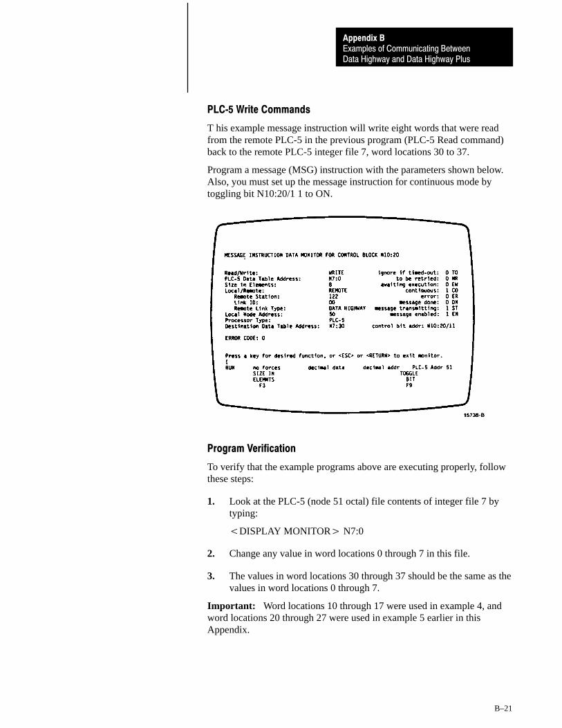
PLC�5 Write Commands
T his example message instruction will write eight words that were readfrom the remote PLC-5 in the previous program (PLC-5 Read command)back to the remote PLC-5 integer file 7, word locations 30 to 37.
Program a message (MSG) instruction with the parameters shown below.Also, you must set up the message instruction for continuous mode bytoggling bit N10:20/1 1 to ON.
Program Verification
To verify that the example programs above are executing properly, followthese steps:
1. Look at the PLC-5 (node 51 octal) file contents of integer file 7 bytyping:
�DISPLAY MONITOR� N7:0
2. Change any value in word locations 0 through 7 in this file.
3. The values in word locations 30 through 37 should be the same as thevalues in word locations 0 through 7.
Important: Word locations 10 through 17 were used in example 4, andword locations 20 through 27 were used in example 5 earlier in thisAppendix.

Publication 1785-6.5.1 - February, 1988
Allen�Bradley, a Rockwell Automation Business, has been helping its customers improve pro�ductivity and quality for more than 90 years. We design, manufacture and support a broad rangeof automation products worldwide. They include logic processors, power and motion controldevices, operator interfaces, sensors and a variety of software. Rockwell is one of the worldsleading technology companies.
Worldwide representation.
Argentina • Australia • Austria • Bahrain • Belgium • Brazil • Bulgaria • Canada • Chile • China, PRC • Colombia • Costa Rica • Croatia • Cyprus • Czech Republic •Denmark • Ecuador • Egypt • El Salvador • Finland • France • Germany • Greece • Guatemala • Honduras • Hong Kong • Hungary • Iceland • India • Indonesia •
Ireland • Israel • Italy • Jamaica • Japan • Jordan • Korea • Kuwait • Lebanon • Malaysia • Mexico • Netherlands • New Zealand • Norway • Pakistan • Peru •Philippines • Poland • Portugal • Puerto Rico • Qatar • Romania • Russia�CIS • Saudi Arabia • Singapore • Slovakia • Slovenia • South Africa, Republic • Spain •Sweden • Switzerland • Taiwan • Thailand • Turkey • United Arab Emirates • United Kingdom • United States • Uruguay • Venezuela • Yugoslavia
Allen�Bradley Headquarters, 1201 South Second Street, Milwaukee, WI 53204 USA, Tel: (1) 414 382�2000 Fax: (1) 414 382�4444
Publication 1785-6.5.1 - February, 1988 PN 404619101Copyright 1985 Allen�Bradley Company, Inc. Printed in USA


![[XLS]On Highway Motorcycle 2015 Certification Data · Web viewTitle On Highway Motorcycle 2015 Certification Data Subject This is the On Highway Motorcycle Certification and Greenhouse](https://static.fdocuments.net/doc/165x107/5b04384b7f8b9a89208d4308/xlson-highway-motorcycle-2015-certification-data-viewtitle-on-highway-motorcycle.jpg)