1592025400 iPRO-GENIUS EN 090325 - ECDecd.com.pl/Dokumenty/IC/iPRO-GENIUS_EN_090325.pdf ·...
141
________________________________________________________________________________________________________ 1592025400 – Vers. 1.0 - 1 - iPRO PROGRAMMABLE CONTROLLER OPERATION MANUAL iPRO.GENIUS Vers. 1.0
Transcript of 1592025400 iPRO-GENIUS EN 090325 - ECDecd.com.pl/Dokumenty/IC/iPRO-GENIUS_EN_090325.pdf ·...

________________________________________________________________________________________________________ 1592025400 – Vers. 1.0 - 1 -
iPRO PROGRAMMABLE CONTROLLER
OPERATION MANUAL iPRO.GENIUS Vers. 1.0

________________________________________________________________________________________________________ 1592025400 – Vers. 1.0 - 2 -

________________________________________________________________________________________________________ 1592025400 – Vers. 1.0 - 3 -
1. lNDEX 2. WARNING 3. INTRODUCTION
3.1 Main Features 3.2 Technical data 3.3 Alarm Management 3.4 Plant Status Display 3.5 ISaGRAF 3.6 Why ISaGRAF 3.7 Development tools 3.8 Upgrade programs from previous version of ISaGRAF (3.x) 3.9 Minimum system requirement for PC 3.10 Inside the packaging
4. BASIC Input/Output CONFIGURATION
4.1 Power Supply 4.2 Analog Inputs (Probes PTC - NTC) 4.3 Analog Inputs (Pressure transducers 4÷20mA, Probes 0÷20mA) 4.4 Analog Inputs (Pressure transducers 0÷1V, Ratiometric 0÷5V - 0÷10V) 4.5 Analog Inputs (Probes 0÷1V - 0÷10V) 4.6 Analog Outputs (0÷10V - 4÷20mA signal for condenser controls) 4.7 Analog Outputs (PWM signal for fan speed module) 4.8 Analog Outputs (proportional signal 0÷10V - 4÷20mA for actuators and servomotors) 4.9 Analog Outputs (configured to control remote relay) 4.10 Digital Inputs 4.11 Digital Outputs 4.12 Visograph connection 4.13 Expansion module (specifications and connections) 4.14 Other connections
5. HOW TO START
5.1 Ethernet 10/100 connection 5.2 Direct connection (between iPRO and PC with a cable) 5.3 Intranet/Ethernet connection (Local Area Network) 5.4 Port forwarding 5.5 Modem connection
6. ISAGRAF INSTALLATION AND SET-UP
6.1 Requirements 6.2 How to install the ISaGRAF software 6.3 How to download the software from ISaGRAF website 6.4 How to set-up the ISaGRAF program 6.5 Start with the new project
7. THE ISAGRAF WORKBENCH
7.1 Definitions 7.2 How to make a regulator ON-OFF 7.3 Debug Step by Step 7.4 The ISaGRAF instruction manual
________________________________________________________________________________________________________ 1592025400 – Vers. 1.0 - 4 -
8. PROGRAMMING LANGUAGES
8.1 ST language – General concepts 8.2 FBD language – General concepts
8.2.1 FBD example – ON/OFF regulator 8.3 FB function block
8.3.1 Introduction of Function Block FB 8.3.2 How to create the FB 8.3.3 How to use the FB inside the programs 8.3.4 Exportation and Importation of FB
8.4 Configuration files 8.4.1 File CONF 8.4.2 File BIN 8.4.3 File PARAM 8.4.4 File SPALT
9. SECURITY
9.1 How to protect your application/program 9.2 How to transfer or copy the application 9.3 How to protect the function blocks FB
10. HOW TO USE THE USB 11. VISOPROG INSTALLATION AND SET-UP
11.1 How to install VISOPROG software 11.2 License Activation 11.3 How to set-up the VISOPROG program
11.3.1 Environment Language 11.3.2 Environment Connection 11.3.3 Project Options
12. VISOGRAPH 13. THE VISOPROG WORKBENCH
13.1 Introduction 13.2 The VISOPROG environment 13.3 The STAGE area 13.4 The STAGE EDITOR area 13.5 The INFORMATION area
13.5.1 Object Properties 13.5.2 Main View 13.5.3 Variables 13.5.4 Vocabulary 13.5.5 View State
13.6 How to create a new project 13.6.1 Fine tuning of your project
13.7 Features included 13.7.1 Buttons combination and actions 13.7.2 Disabled property unchecked (active elements) 13.7.3 Controls visibility 13.7.4 Automatic Stages

________________________________________________________________________________________________________ 1592025400 – Vers. 1.0 - 5 -
14. CONNECTIVITY
14.1 Ethernet 10/100 and Serial bus 14.2 How to configure the bus and variables
14.2.1 Define the BUS (GENLINE board) 14.2.2 Define the I/O (GENAI, GENAO, GENDI, GENDO boards) 14.2.3 Define the new variable(s) in the dictionary 14.2.4 Link between variables and boards
15. ADMINISTRATOR SITE

________________________________________________________________________________________________________ 1592025400 – Vers. 1.0 - 6 -
2. WARNING
WARNING: TO PREVENT FIRE OR ELECTRIC SHOCK, DO NOT EXPOSE THIS APPLIANCE TO RAIN OR MOISTURE.
CAUTION: TO REDUCE THE RISK OF ELECTRIC SHOCK, DO NOT REMOVE COVER (OR BACK). NO USER-SERVICEABLE PARTS INSIDE, REFER SERVICING TO QUALIFIED SERVICE PERSONNEL.
THE LIGHTNING FLASH WITH ARROWHEAD SYMBOL, WITHIN AN EQUILATERAL TRIANGLE, IS INTENDED TO ALERT THE USER TO THE PRESENCE OF UNINSULATED “DANGEROUS VOLTAGE” WITHIN THE PRODUCT’S ENCLOSURE THAT MAY BE OF SUFFICIENT MAGNITUDE TO CONSTITUTE A RISK OF ELECTRIC SHOCK TO PERSONS.
THE EXCLAMATION POINT WITHIN AN EQUILATERAL TRIANGLE IS INTENDED TO ALERT THE USER TO THE PRESENCE OF IMPORTANT OPERATING AND MAINTENANCE (SERVICING) INSTRUCTIONS IN THE LITERATURE ACCOMPANYING THE APPLIANCE.
WARNING:
Dixell Spa can accept no responsibility for any possible damage due the usage of not supported modems. Dixell Spa. reserves itself the right to modify this manual without notice. The last version available can be downloaded from the website. This controller is compliant with standard EN 12830 if it is used together with probes that are compliant with standard EN 13485
WARNING:
This manual is part of the product and should be kept near the instrument to easy and quick reference. The instrument shall not be used for different purpose from those described in this manual. It cannot be used as a safety device. Check the application limits before proceeding.
WARNING:
Check the supply voltage is correct before connecting the instrument. Do not expose to water or moisture: use the controller only within the operating limits avoiding sudden temperature changes with high atmospheric humidity to prevent formation of condensation. Warning: disconnect all electrical connections before any kind of maintenance. Fit the probe where it is not accessible by the End User. The instrument must not be opened. Consider the maximum current which can be applied to each relay (see Technical Data). Ensure that the wires for the probes, loads and the power supply are separated and far enough from each other, without crossing or intertwining. In case of applications in industrial environments, the use of mains filters (our mod. FT1) in parallel with inductive loads could be useful.
DIXELL reserves the right to modify or change its products without prior warning.

________________________________________________________________________________________________________ 1592025400 – Vers. 1.0 - 7 -
3. INTRODUCTION 3.1 Main Features
iPRO family, dedicated whether for HVAC units (iPRO Chill and Domo) or for general
purposes and refrigeration (iPRO Genius), is characterized by the most advanced
technology in connectivity and processing speed.
It is based on a powerful platform that includes one hardware configuration that is able to
expand the actual solution in the market, and a software that, thanks to the ISaGRAF®
development environment allows the development through standard programming
languages.
An easy and useful HMI is also guaranteed through the VISOGRAPH graphic display, as
the expandability and the solution to many applications are satisfied with a complete range
of accessories, among which, I/O expansion modules and proportional electronic valve
management, modem, wiring…
The iPRO Genius family satisfy all requirements regarding the controlling and management
of refrigeration, heating, ventilation, electric power and all building automation services.
They are suited for all applications in the PLC world and they find applications in many
shopping centres, hospitals, airports, boatyards, energy management plants, and so on…
These controllers provide a high level of technology for ease of external connectivity and
programmability providing simple answers to every application’s needs, while ensuring a
complete local or remote monitoring.
• Fully programmable controllers and high connectivity.
• VISOGRAPH programmable graphic display (LCD – 240x96 pixels).
• Ethernet for connection to an intranet-internet network and to others programmable
controllers for a distributed application management.
• USB (host) that allows the download of applications, parameters, data/alarm logger
and the applications and parameters upload. It is possible also to upgrade the BIOS
of microprocessor.

________________________________________________________________________________________________________ 1592025400 – Vers. 1.0 - 8 -
• CANBus digital communication serial protocol for the connection to other
programmable controllers, to I/O expansion modules.
• Two master and slave RS485 serial output.
• ModBUS-RTU standard communication protocol that allows connection to Dixell
digital controllers, to XWEB supervising and controlling systems or to applications
developed by third Party Systems.
• BACnet communications allows the system to have easy and immediate integration
with different manufactures ensuring a complete collaboration.
• The possibility to have a connection to the expansion modules in order to increase
system capacity.
• 20VA max power absorption.
3.2 Technical data
LINUX Operative System 200MHz CPU 32bit processor 32MB RAM memory 128MB flash memory capacity (80MB free) 10 configurable Analog Inputs (configurable as Digital Inputs) 6 Analog Outputs (configurable as Digital Outputs) 20 Digital Inputs (free contacts) 15 Digital Outputs (Relay 5A) Ethernet 10/100 Modem (Internal and External) 2 Master bus (RS485 and Can-bus) 1 Slave bus (RS485 MODBUS RTU) 1 USB 1 VISOGRAPH connection Power Supply: 24 Vac-dc Operating temperature: -10 ÷ 60 °C Storage temperature: -20 ÷ 70 °C Relative humidity: < 90% (no condensing) Power consumption: 10W Protection: IP20 (IP40 for VISOGRAPH)

________________________________________________________________________________________________________ 1592025400 – Vers. 1.0 - 9 -
3.3 Alarm Management
The alarm management system is the fundamental element that increases the plant
efficiency, ensuring an immediate identification of plant problems and activates automatic
strategies to prevent possible damages. The following possible options are available with
iPro GENIUS.
• Alarm sending management by e-mail or sms
• Direct internet connection
• Point-to-point connection via modem, GSM and PDA modem
• Remote command sending via sms
• Possibility of updating the (iPro) on-board software via e-mail
3.4 Plant Status Display
The plant maintenance staff can easily have a report of application status in order to decide
how and when to intervene. The report contains all of the most important values, the plant
status and operating set point.
3.5 ISaGRAF
In order to create programs that will be uploaded into the iPro series Dixell has selected
ISaGRAF®; a software environment that enables you to create local or distributed control
systems. ISaGRAF® offers a combination of a highly portable, robust management engine
(Virtual Machine) and an intuitive application development environment (Workbench). The
output of the development environment is selectable as either portable “C” source code or
TIC (target independent code). The ISaGRAF® Virtual Machine is a powerful, optimized
and very fast control engine that executes the TIC. Virtual Machine and all options are
offered ready to use on NT, Linux, CE 3.0 and QNX. Additionally, this control engine has
been designed such that the source code of the Virtual Machine is available in a toolkit

________________________________________________________________________________________________________ 1592025400 – Vers. 1.0 - 10 -
format, providing portability to any OS on any hardware platform. The Enhanced options for
ISaGRAF® transform this outstanding controller into a top of the line PLC, DCS or RTU.
3.6 Why ISaGRAF ?
• This development environment is international, complete, standard
• Is ideal for small applications but it can manage several I/O points
• It is the most used (more than 40.000 developers in the world and more than
500.000 applications in the last 10 years)
• It includes 5 different programming languages coded according to IEC61131
• It integrates the best system for simulation and remote debugging
• It is supported all over the world (essential for training and assistance)
The ISaGRAF® Application development Workbench supports all the standard IEC 61131
control program languages plus Flow Chart.
• SFC: Sequencial Function Chart
• ST: Structured Text
• FBD: Function Block Diagram
• IL: Instruction List
• FC: Flow Chart
• LD: Ladder Diagram
3.7 Development tools
IPRO-TOOL is a complete tool, provided by Dixell, that allows the final user to work
independently to create programs for iPRO controllers, taking advantage of all the
programmable series potential. The package includes manuals and the WIZMATE software,
a useful instrument that allows a simple iPRO controllers programming mode. Another utility
provided by Dixell is the VISOPROG software for the graphic interfaces creation of
VISOGRAPH displays.

________________________________________________________________________________________________________ 1592025400 – Vers. 1.0 - 11 -
The user can choose between two options:
3.8 Upgrade programs from previous version of ISaGRAF (3.x)
For iPRO is possible to manage programs that have been developed with ISaGRAF 3.x
version; it is not possible the opposite.
If the program contains ISaGRAF standard function block, they can be converted
automatically.
If the program contains ISaGRAF custom functional block (for example blocks made from
other company), it will be necessary to codify and rewrite them for the new version.
3.9 Minimum system requirement for PC
When connecting through the LAN, the PC client computer must have installed these
components:
• Windows 98®, Windows 2000, WindowsXP.
• Pentium II 300MHz with 64Mb ram or higher
• Java Virtual Machine
• Explorer 5.5 or higher, Firefox

________________________________________________________________________________________________________ 1592025400 – Vers. 1.0 - 12 -
If necessary, inside the CD-ROM you will find the Java Virtual Machine program distributed
by Sun® Microsystems.
Dixell S.p.a. is not responsible for any kind of damage occurring after the loading of the
Java Virtual Machine program into the user’s PC.
3.10 Inside the packaging

________________________________________________________________________________________________________ 1592025400 – Vers. 1.0 - 13 -
4. BASIC Input/Output CONFIGURATION
Configurable means that every inputs or output can be configured different each other.

________________________________________________________________________________________________________ 1592025400 – Vers. 1.0 - 14 -
4.1 Power Supply
4.2 Analog Inputs (Probes PTC-NTC)

________________________________________________________________________________________________________ 1592025400 – Vers. 1.0 - 15 -
4.3 Analog Inputs (Pressure transducers 4÷20mA, probes 0÷20mA)
4.4 Analog Inputs (Pressure transducers 0÷1V, Ratiometric 0÷5V - 0÷10V)
4.5 Analog Inputs (Probes 0÷1V - 0÷10V)

________________________________________________________________________________________________________ 1592025400 – Vers. 1.0 - 16 -
4.6 Analog Outputs (0÷10V - 4÷20mA signal for condenser controls)
4.7 Analog Outputs (PWM signal for fan speed module)

________________________________________________________________________________________________________ 1592025400 – Vers. 1.0 - 17 -
4.8 Analog Outputs (proportional signal 0÷10V, 4÷20mA for actuators/ servo-motors)
4.9 Analog Outputs (configured to control remote relay)

________________________________________________________________________________________________________ 1592025400 – Vers. 1.0 - 18 -
4.10 Digital Inputs
4.11 Digital Outputs

________________________________________________________________________________________________________ 1592025400 – Vers. 1.0 - 19 -
4.12 Visograph connection
IT IS VERY IMPORTANT TO RESPECT THE POLARITY OF CONNECTIONS TO AVOID
THE DAMAGING OF THE VISOGRAPH.

________________________________________________________________________________________________________ 1592025400 – Vers. 1.0 - 20 -
4.13 Expansion Module (specifications and connections)
Power supply: 24V Vac/dc Analog Inputs: 7 configurable
0÷1V, 0÷5V, 0÷10V, 0÷20mA, 4÷20mA, NTC, PTC, DI
Analog Outputs: 3 configurable
0÷10V ( or DO for relay) Digital Inputs: 3 (free contacts) Digital Output: 6 relay 5A 250V Connection: 1 CANBus Address: Dip switch 4 positions
Can bitrate = 100Kbit/s (set-up this value through the browser

________________________________________________________________________________________________________ 1592025400 – Vers. 1.0 - 21 -
4.14 Other connections
For all the other connections, please refer to the section No. 14.

________________________________________________________________________________________________________ 1592025400 – Vers. 1.0 - 22 -
5. HOW TO START 5.1 Ethernet 10/100 connection
With this connection is possible:
• To connect the iPRO with the personal computer; through ISaGRAF workbench you
download and debug the application.
• To connect more iPRO; different applications on different iPRO to exchanges
variables.
• To send mail and sms; you can program your iPRO so that it can sends mail/sms on
time or on demand.
• To visit your own website; you can program iPRO with your own web site. With a
standard browser, a user can read/write variables.
5.2 Direct connection (between iPRO and PC with a cable) With this kind of connection is possible to connect directly your personal computer with the
programmable controller iPRO. In this case, you need a standard “Crossover Cable” (cod.
Dixell CAB/WEB/PC). The PC can communicate with the iPRO only if the settings in the
devices are aligned; this means that the PC and the iPRO have to work in the same
network.
The procedure is the following:
iPROCable
(Crossover)
PC

________________________________________________________________________________________________________ 1592025400 – Vers. 1.0 - 23 -
• Disconnect your computer from the data network of your company and connect the
PC with the iPRO through the Crossover cable.
• The personal computer has to be set in the same network of the iPRO.
o In the windows environment click with the mouse on “start” button .
o Choose “Control Panel” and select “Network and dial-up connections” .
o Choose “Local area connection” .
o Choose “Properties” and double click on “Internet Protocol (TCP/IP)”.
o In this window set the following parameters (as showed in the picture):
IP address: 192.168.0.200
Subnet Mask: 255.255.255.0
o Click “OK” to confirm.

________________________________________________________________________________________________________ 1592025400 – Vers. 1.0 - 24 -
Launch the browser in your computer and write the following web site address:
http://192.168.0.250/panel (if your IP is different, write the correct one):
If necessary is possible to change the IP address; click the Configuration button and in the
IP box write the new address (for example if your IP address is: 192.168.0.233).
Click “OK” to confirm the operation.

________________________________________________________________________________________________________ 1592025400 – Vers. 1.0 - 25 -
If everything is ok, the message will be:
Now it is necessary to restart the iPRO. To test the connection follows the procedure in the chapter 5.3.

________________________________________________________________________________________________________ 1592025400 – Vers. 1.0 - 26 -
5.3 Intranet / Ethernet connection (Local Area Network) The Intranet or Ethernet connection should be initially managed by the net administrator
that will assign one free IP address to reach the iPRO. This number is an example of what
you should expect with the default IP of the iPRO: 192.168.0.250.
After receiving the address from your network Administrator the iPRO must be set with this
number (through the procedure described in the chapter 5.2).
Use a standard RJ45 network cable to connect the unit to your existing LAN.
The Intranet method allows the connection to interact with iPRO from all the PC Clients.
To check if the connection has been established try in this way:
• From your computer launch: start - run
• In the box write the following string:
• Then click OK.

________________________________________________________________________________________________________ 1592025400 – Vers. 1.0 - 27 -
If the connection is OK, in this window you will see the following information:
5.4 Port forwarding Port forwarding allows remote computers (e.g. public machines on the Internet) to connect
to a specific computer within a private LAN.
The ports that have to be opened are:
• 22 for SSH protocol
• 80 for browser (internet explorer, firefox, …)
• 1131 for ISaGRAF WorkBench
• 6666 used for remote update
5.5 Modem connection

________________________________________________________________________________________________________ 1592025400 – Vers. 1.0 - 28 -
6. ISAGRAF INSTALLATION AND SET-UP 6.1 Requirements To develop the software with ISaGRAF are necessary:
• Software (it is possible to install the program from the CD or download it from the
ISaGRAF Website).
• To have the ISaGRAF USB KEY
6.2 How to install the ISaGRAF software Insert the CD in your computer; the CD will start automatically.
You have to choose the first option.
You have to select: “ I accept the terms” …and then: “Next”

________________________________________________________________________________________________________ 1592025400 – Vers. 1.0 - 29 -
Please install ONLY the programs selected as showed here below:
…and then: “Next”
…and then: “Next”
These are the programs that you are installing…

________________________________________________________________________________________________________ 1592025400 – Vers. 1.0 - 30 -
…select: “Install”
Choose the languages…
…select: “Next”
At the end of the installation, please restart the computer
…select: “Finish”

________________________________________________________________________________________________________ 1592025400 – Vers. 1.0 - 31 -
6.3 How to download the software from ISaGRAF website Open the browser in your computer and write the following address: www.isagraf.com and choose Downloads.
Then choose the ISaGRAF version to download (before to do this, check the Dixell website to verify the latest revision approved by Dixell).
The procedure to install and set-up of ISaGRAF software is the same as above.

________________________________________________________________________________________________________ 1592025400 – Vers. 1.0 - 32 -
6.4 How to set-up the ISaGRAF program First, it is necessary to copy in this directory of your PC:
• C:\Programmi\ICS Triplex ISaGRAF\Projects\ISaGRAF 5.1\Prj the folder “Dixell_template” as showed here below (you can find and download this folder directly from the Support Area inside the Dixell website in the “ISaGRAF section).
This is the Template project necessary to start with your new project. Second, in the disk “C:\” , copy the folder “Dixell” as showed here below.
Inside this folder, there is the DIXELL GFL (general function library). You can find this folder inside the Dixell website in the “ISaGRAF Function Blocks” section.

________________________________________________________________________________________________________ 1592025400 – Vers. 1.0 - 33 -
6.5 Start with the new Project Launch the ISaGRAF program and select:
File - Open Project/Library
The file to open is inside the project that we have saved in:
• C:\Programmi\ICS Triplex ISaGRAF\Projects\ISaGRAF 5.1\Prj
Double click on Prj
This is the folder where your project has been saved

________________________________________________________________________________________________________ 1592025400 – Vers. 1.0 - 34 -
When you have opened your project, it is important to import the “tdb” file.
This file has been generated by Dixell to describe the property of iPRO to the ISaGRAF
workbench; this file include all the latest information about the improvement of the standard
application of iPRO. To import the file in the project: File Import Plc Definition .
Import the “tdb” file (you can find and download this file directly from the Dixell the Support Area inside the Dixell website in the “ISaGRAF section).
The default name of the tdb file is “ARM_TARGET_L6.tdb”.
Open the file PrjLibrary

________________________________________________________________________________________________________ 1592025400 – Vers. 1.0 - 35 -
After these operations save and compile the project. To check if your application is ok, after the compilation, you can see on the bottom of
ISaGRAF window if there are errors or warnings.
If there are some errors you have to check your application otherwise you can’t download it
in the device. If there are some warnings, you can download the application.
To remove the warning messages, follow this procedure:
1. Project Clean Project/Library
2. Project Clean Resource
3. Tool Compact Database
Then save and compile again; The new messages should be:
All these file are available in the Dixell web site (www.dixell.com) inside the support area.
Pay attention because if you have already developed your project with an old version of the
tdb file is not necessary to import the new one in your project.
This operation is necessary only when you start with a new project and if the developer
needs to use a new Function Block not available in the previous versions.

________________________________________________________________________________________________________ 1592025400 – Vers. 1.0 - 36 -
The last operation to do to complete the set-up is to define the IP address in the ISaGRAF
workbench.
Click the icon: or and then double click on vertical bar: If the vertical bar is not visible, move the “Config” window until the vertical bar will appear. Write inside the box the IP address of your iPRO, then OK.
Now the set-up of ISaGRAF is completed and you can start with your application.
Double click on vertical bar
Config window

________________________________________________________________________________________________________ 1592025400 – Vers. 1.0 - 37 -
7. THE ISAGRAF WORKBENCH 7.1 Definitions
Before to start with the examples is important to fix some important definitions.
Resource: it is your project; inside there are the elements of your project.
The elements of your project are:
Programs: it is the software that you develop to execute your application.
In this picture, for every PLC Cycle, iPRO executes
the programs: Read_Inputs Regulator_status_of_controller
Regulator _Fans ……
The number and the order of the programs depend on
your software.
PLC Cycle: it is the time that synchronize the execution of
the programs. For every PLC cycle, iPRO executes
the list of the program.
It is important to define this value considering that the CT must be:
• NEVER = 0ms (zero ms)
• ALWAYS compare the Current Cycle Time (CCT) and the Programmed
Cycle Time (PCT) with the following rule:
PCT > (2 x CCT)

________________________________________________________________________________________________________ 1592025400 – Vers. 1.0 - 38 -
To check the Cycle Timing choose: Edit Properties Settings
During the Debug is possible to verify if the PCT is correct.
Choose: Debug Diagnosis, and in the Timing tab all these information are
available.
________________________________________________________________________________________________________ 1592025400 – Vers. 1.0 - 39 -
Function blocks: they are a general routine (software) executed in different programs.
It is possible to “call” the FB in every part of the program; in this way is
not necessary to write the same program a lot of time. Besides you can
save them in the library and also protect them with a password.
These FB can be developed by ISaGRAF, Dixell and from third party.
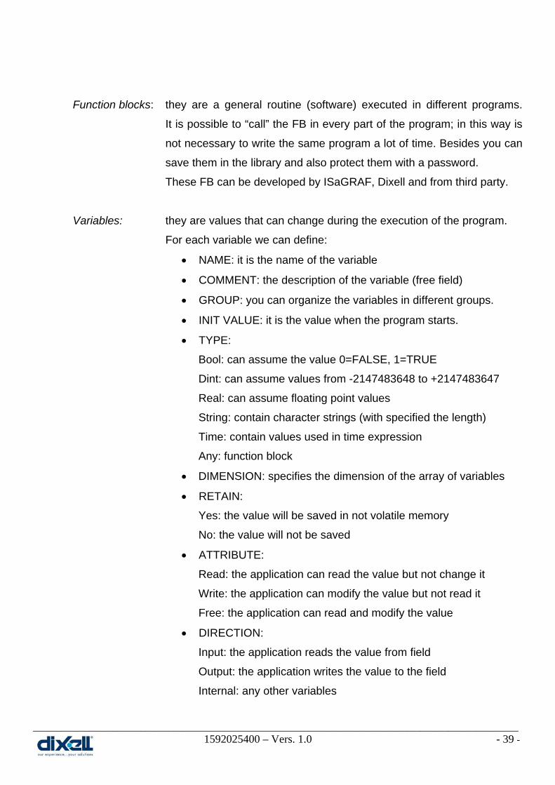
Variables: they are values that can change during the execution of the program.
For each variable we can define:
• NAME: it is the name of the variable
• COMMENT: the description of the variable (free field)
• GROUP: you can organize the variables in different groups.
• INIT VALUE: it is the value when the program starts.
• TYPE:
Bool: can assume the value 0=FALSE, 1=TRUE
Dint: can assume values from -2147483648 to +2147483647
Real: can assume floating point values
String: contain character strings (with specified the length)
Time: contain values used in time expression
Any: function block
• DIMENSION: specifies the dimension of the array of variables
• RETAIN:
Yes: the value will be saved in not volatile memory
No: the value will not be saved
• ATTRIBUTE:
Read: the application can read the value but not change it
Write: the application can modify the value but not read it
Free: the application can read and modify the value
• DIRECTION:
Input: the application reads the value from field
Output: the application writes the value to the field
Internal: any other variables

________________________________________________________________________________________________________ 1592025400 – Vers. 1.0 - 40 -
• ADDRESS: where to save the value of the variable
In the example here below, it is possible to understand how to define the variables.
There are some important information that have to be taken in consideration when:
the TYPE of the variable is REAL; use this kind of variable only if strictly necessary
(for operation with Log, Exp, Cos,…).
An example is for the temperature: if the value is 25.4°C instead of to work with
REAL variables, we can consider the temperature as DINT so we can work with 254
as decimal.
the RETAIN is Yes; don’t change the value frequently because every memory has a
maximum number of writing and the application can damage the flash memory.
The minimum period suggested is 30 minutes.

________________________________________________________________________________________________________ 1592025400 – Vers. 1.0 - 41 -
7.2 How to make a regulator ON-OFF The purpose of this example is to introduce how to develop a program with ISaGRAF; this
first example will be developed with the ST language.
Our target is to create a Regulator ON-OFF for Compressor (Direct Action).
The diagram of this regulator is:
The meaning of this diagram is:
• IF Temperature is higher than SET+BAND the compressor is ON
• IF Temperature is lower than SET the compressor is OFF
With these information is clear that our VARIABLES are:
• Temperature, type DINT
• SET, type DINT
• BAND, type DINT
• Compressor, type BOOL
Now we can create a new variable group:

________________________________________________________________________________________________________ 1592025400 – Vers. 1.0 - 42 -
Now the new group has been created and we have called it “Group1”.
Double click on Group1:
Double click below name to fill in all the fields (Name, Comment, Type, Address…)
For each variable we have to define the characteristics:
Here we have also define the “Address”; it is necessary to read the value from Visograph. Now we are ready to add a new ST program and we call it “Regulator_for_compressor”.

________________________________________________________________________________________________________ 1592025400 – Vers. 1.0 - 43 -
Change the window from the Dictionary to the Program :
Click on Insert Add Program and choose the language that you prefer:
This example will be developed in ST language.
The new program will be called Regulator_for_compressor.
The next step is to write the program (double click on Regulator_for_compressor):

________________________________________________________________________________________________________ 1592025400 – Vers. 1.0 - 44 -
In the example here above, the variables are not linked with the physical output; these
variables are only logical. To link these variables with the physical output we have to write
another program.
The new program will be:
Comment
Program
Comment

________________________________________________________________________________________________________ 1592025400 – Vers. 1.0 - 45 -
The physical input and output are defined inside the Variable Groups “SysParameters”.
The AI are the analog inputs, the DI are the digital inputs, the AO are the analog outputs
and the DO are the digital outputs.
The ConfAI is the value to configure the probe type; for example if your AI01 is a PTC
probe, ConfAI01 = 1.
It is also possible to define immediately the physical I/O; in this case the program will be:
We have substitute the logical variables with the physical variables.
Now we can “SAVE” the project and……..

________________________________________________________________________________________________________ 1592025400 – Vers. 1.0 - 46 -
………and “REBUILD PROJECT”.
If the program is ok, in the bottom of the ISaGRAF window, the message will be:
At this moment, we are able to execute the program in two different ways:
SIMULATION
Execution without the iPRO; this is the first debug of the program because it is
immediate and complete (see page 48 for procedure).
DEBUG TARGET
The application is running on iPRO. Before to do this is necessary to download
the project into the iPRO; click the icon to select the project to download.

________________________________________________________________________________________________________ 1592025400 – Vers. 1.0 - 47 -
In this window choose “Select All” and then “Download”.
Then “Stop and download”.
At the end of the transferring this message will appear in the bottom of ISaGRAF.

________________________________________________________________________________________________________ 1592025400 – Vers. 1.0 - 48 -
The red semaphore means that the SIMULATION or DEBUG TARGET are running.
To stop the execution is enough to click on semaphore.
During the execution of the program we can read, write and lock the variables.
If you click this icon the variables will appear; with this window is possible to check
the status of your application.
We can force the value of the input; for example we want to switch on the compressor.
Double click in the box of Logical Value of the temperature: try to insert the value “60” and
then confirm with “Write”:
We are checking the value of our variables (Group1) but we can also to check the value of all the other variables present

________________________________________________________________________________________________________ 1592025400 – Vers. 1.0 - 49 -
Here below you can see what is happened:
It is also possible to lock and unlock the variable; for example we can lock the variable of
compressor. During the test, to avoid to damage the compressor, we can lock the
compressor in off (variable must be FALSE) and then change all the other variables to
understand what happen in all the other resource of our application (fan, pump, valve,…).
Here above the information are very clear; in our application the compressor should be on
(TRUE) but, due the variable lock as FALSE, the compressor is off. Now you can change all
the other variables and in any case the compressor will be off.
________________________________________________________________________________________________________ 1592025400 – Vers. 1.0 - 50 -
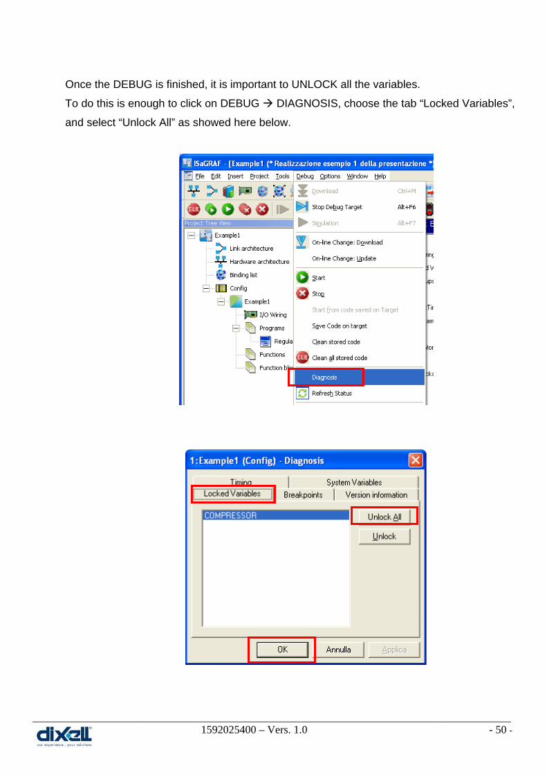
Once the DEBUG is finished, it is important to UNLOCK all the variables.
To do this is enough to click on DEBUG DIAGNOSIS, choose the tab “Locked Variables”,
and select “Unlock All” as showed here below.

________________________________________________________________________________________________________ 1592025400 – Vers. 1.0 - 51 -
7.3 Debug Step by Step This function is useful to check in your application what happen when the inputs change;
you can see in which part of your application the program is stopped because it is waiting
some new information or event.
To enable this function, click on the Resource bar and , with the
right button of the mouse, chose Properties; in window here below, choose the tab
“Target/Code” and check “Generate debug information”.
Then, through the icon , select the program to debug:
Now the Debug Step by Step is enable; the next operation to do is to decide in which part of
the application or program put the “Breakpoints”.

________________________________________________________________________________________________________ 1592025400 – Vers. 1.0 - 52 -
Open your program and with this icon add the breakpoints; place the cursor at the
beginning of the line of your program and click the breakpoint icon.
You can add other breakpoint.
The red point means that there is a breakpoint in that line of the program.

________________________________________________________________________________________________________ 1592025400 – Vers. 1.0 - 53 -
To check how many breakpoints there are in your application and if you need to remove
them, click the icon :
If the step by step set-up is completed, save and compile the application.
To test the system there are two ways:
• with SIMULATION .
• with DEBUG TARGET ; in this case the following operations are necessary:
o download the application with the breakpoints in the target
o disable the Watchdog (see the “Website for iPRO” chapter)
BE AWARE: when the debug test has been completed and you are in the DEBUG
TARGET, to enable the Watchdog is necessary to reboot the Target (iPRO).
When you will launch the debug, the ISaGRAF workbench will ask you the following
information; confirm with “Yes” or “Yes to all”.

________________________________________________________________________________________________________ 1592025400 – Vers. 1.0 - 54 -
The window with your application will be open; a yellow arrow will show you the position
where the debug is arrived (obviously if there are breakpoints).
The commands available for the “Debug Step by Step” are:
• Switches an application to “real-time” mode”
• Switches an application to “cycle-to-cycle” mode
• Executes one cycle
• Steps to the next
• Steps into the next
• Locates the current step
• Stop the debug
Our Debug is arrived here

________________________________________________________________________________________________________ 1592025400 – Vers. 1.0 - 55 -
7.4 The ISaGRAF instruction manual Once you have installed the ISaGRAF environment, it is possible to find the complete
documentation of ISaGRAF development tool inside the folder:
C:\Programmi\ICS Triplex ISaGRAF\Documentation 5.1\Users Guide\.......\workbench.pdf

________________________________________________________________________________________________________ 1592025400 – Vers. 1.0 - 56 -
8. PROGRAMMING LANGUAGES 8.1 ST language – General concepts
The environment of ST language is composed by:
• STATEMENT
:= assignment
( ) priority
IF, THEN, ELSE, ELSIF, END_IF; binary selection
CASE, OF, ELSE, END_CASE; selection
WHILE, REPEAT, END_WHILE, END_REPEAT; iterations
FOR, TO, BY, DO, END_FOR; indexed iterations
RETURN; program termination
EXIT; iteration statement termination
BOOLEAN OPERATOR (decreasing priority) NOT boolean negation
AND boolean AND
OR boolean OR
XOR boolean exclusive OR
=, <>, >=, <=, <, > comparisons
+, -, *, / arithmetic operators
Beware of:
WHILE and REPEAT have to be used with special care.
arithmetic operator can be used for integer DINT or REAL.
• TIME
+ addition
- subtraction
Beware of subtraction: negative timer as result means nothing.

________________________________________________________________________________________________________ 1592025400 – Vers. 1.0 - 57 -
• STRING
ASSIGNMENT := direct copy
CONCATENATION + concatenates two strings
COMPARISON =, <>, >=, <=, >, < alphabetical order
• CONVERSION FUNCTION
ANY_TO_BOOL conversion to boolean
ANY_TO_DINT conversion to double INT
ANY_TO_REAL conversion to real
ANY_TO_TIME conversion to timer
ANY_TO_STRING conversion to string
Example:
If we have two variables: SEC (type DINT) and SEC1 (type TIME) the assignation:
SEC1 := SEC; this is wrong
SEC1 := ANY_TO_TIME (SEC*1000); this is correct
• FUNCTION BLOCK CALLING
Declare instance into dictionary (each instance have a unique name)
TON_Instance1 is an instance of TON
Call instance of the FB (activation of instance by-passing the input parameters)
TON_Instance1 ( TRUE, t#3s)
Get the returning parameters
End_Time := TON_instance1.Q;
Current_Time := TON_instance1.ET;

________________________________________________________________________________________________________ 1592025400 – Vers. 1.0 - 58 -
8.2 FBD language – General concepts

________________________________________________________________________________________________________ 1592025400 – Vers. 1.0 - 59 -
8.2.1 FBD example – ON/OFF regulator
The purpose of this example is to develop the same example of before but with the FBD
language.
The steps are the same of example No.1 except for the step when you have to add the
program; in this case you have to add the FBD program.
Pay attention because in this example we have called the FBD program with the same
name of the ST program; inside one project is not possible to have different program with
the same name
The next step is to write the program (double click on Regulator_for_compressor):

________________________________________________________________________________________________________ 1592025400 – Vers. 1.0 - 60 -
Once the FBD is open, we have to put the elements of our application; the first element is
the Hysteresis block. Click the icon and then positioning it in the window.
With the tab here below select the block and then press OK.
To confirm the operation click the icon .
The other elements to put are the variables (defined in the Group1).
Click the icon and then positioning them in the window.
With the tab here below you can select the variables.
To confirm the operation click the icon .
The connect the variables with the block as showed here below:

________________________________________________________________________________________________________ 1592025400 – Vers. 1.0 - 61 -
From now, all the other steps are like the example1.
This means that you can develop the program with a different language but at the end the
result is the same; summarizing:
• Before writing software, split the application in programs.
• Recognize if these programs have similar parts.
• Recognize if the FB necessary for your programs already exist
Take the FB from ISaGRAF library
Take the FB from Dixell Library
Take the FB from your personal library
Develop a new FB for your application
• For any program define the Variable Group
• Use the ST language to develop the new FB and use St or FBD language to develop
your programs.

________________________________________________________________________________________________________ 1592025400 – Vers. 1.0 - 62 -
8.3 Function block FB 8.3.1 Introduction of Function Block FB
The Function Block are an applications/programs or a part of the applications/programs and
they can be called when and all the times that you need.
To use the FB means that:
• it is not necessary to write a lot of time the same program
• it is possible to debug the single FB
• you can create and save for yourself a personal library
• you can use a lot of FB made by ISaGRAF, Dixell or third party
• the debug of the whole program is more quickly (save time and money)
Here below you can see some typical FB made by ISaGRAF and Dixell:
The FB is composed by some Inputs (on the left side) and some Outputs (on the right side).
When you use the FB in your program is enough to send them only the value of the
variables to get the result; it is not necessary to know what happen inside the blocks.
Another important characteristic of the FB are:
• the FB can be visible and modifiable
• the FB can be visible and modifiable with password
• the FB is protected (non visible and not modifiable)
FB made by ISaGRAF FB made by Dixell

________________________________________________________________________________________________________ 1592025400 – Vers. 1.0 - 63 -
8.3.2 How to create the FB
Starting from the Example No. 1, we can consider to control the following resources:
• Fan motor
• Alarm for high temperature
• Alarm for low temperature
The diagram for each of them is:
Practically we can see that for every diagram we have:
• An analog variable that drives the output
• A bool variable as output
• A specific input value where the output is ON
• A specific input value where the output is OFF
The only difference is the action : DIRECT or INVERSE.
Inverse Action
Direct Action
Inverse Action

________________________________________________________________________________________________________ 1592025400 – Vers. 1.0 - 64 -
We can summarize the four diagrams in 2 diagrams:
Now we have all the elements to create a FB that we call ONOFF_Regulator.
Add a new Function Block using the ST language:
This is our new function block; click on it with the right key of the
mouse and choose “Parameters / Local Variables”.

________________________________________________________________________________________________________ 1592025400 – Vers. 1.0 - 65 -
Add the 5 variables:
Double click on ONOFF_Regulator to write the program in ST language:
This is the Function Block that we have created just now:
Remember that you can use this FB when you want and all the times that you need.
________________________________________________________________________________________________________ 1592025400 – Vers. 1.0 - 66 -
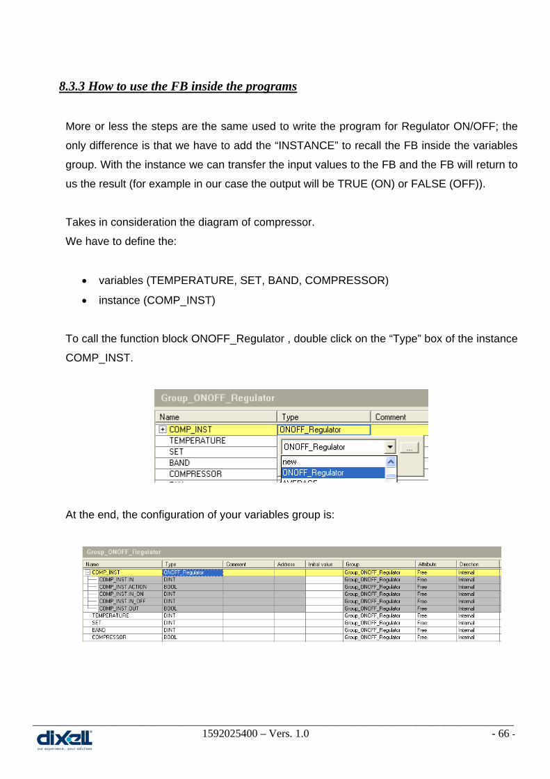
8.3.3 How to use the FB inside the programs
More or less the steps are the same used to write the program for Regulator ON/OFF; the
only difference is that we have to add the “INSTANCE” to recall the FB inside the variables
group. With the instance we can transfer the input values to the FB and the FB will return to
us the result (for example in our case the output will be TRUE (ON) or FALSE (OFF)).
Takes in consideration the diagram of compressor.
We have to define the:
• variables (TEMPERATURE, SET, BAND, COMPRESSOR)
• instance (COMP_INST)
To call the function block ONOFF_Regulator , double click on the “Type” box of the instance
COMP_INST.
At the end, the configuration of your variables group is:

________________________________________________________________________________________________________ 1592025400 – Vers. 1.0 - 67 -
The last step is to write the program with ST and FBD languages:
It is very important to understand that the list of the inputs is not random; the sequence of
the inputs must be like the sequence of the instance.
For all the other resources is enough to add the variables, instances and program for each
of them.
TEMPERATURE FALSE
SET+BAND SET

________________________________________________________________________________________________________ 1592025400 – Vers. 1.0 - 68 -
To complete the job, SAVE, COMPILE and EXECUTE your project.
The same program written with FBD language will be:
The considerations regarding the FB are:
• The description of regulator is immediate and complete.
• Every regulator is based on Function Block “ONOFF_Regulator”.
• Function block are made by everybody.
• Function blocks can have up to 128 outputs and inputs.
________________________________________________________________________________________________________ 1592025400 – Vers. 1.0 - 69 -
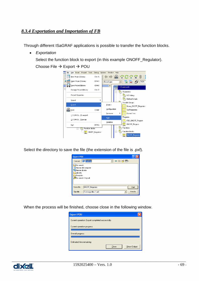
8.3.4 Exportation and Importation of FB
Through different ISaGRAF applications is possible to transfer the function blocks.
• Exportation
Select the function block to export (in this example ONOFF_Regulator).
Choose File Export POU
Select the directory to save the file (the extension of the file is .pxf).
When the process will be finished, choose close in the following window.
________________________________________________________________________________________________________ 1592025400 – Vers. 1.0 - 70 -
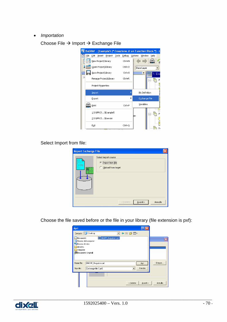
• Importation
Choose File Import Exchange File
Select Import from file:
Choose the file saved before or the file in your library (file extension is pxf):

________________________________________________________________________________________________________ 1592025400 – Vers. 1.0 - 71 -
Select the exchange file to import:
Select the elements to import:
If you want it is possible to change the name of function block
Check the result of procedure and exit:
Now in your project, in the function block folder you will find the ONOFF_Regulator.

________________________________________________________________________________________________________ 1592025400 – Vers. 1.0 - 72 -
8.4 Configuration files The files, managed through the USB key, are recognized with different kind of “extension
file”; here below the differences.
8.4.1 File CONF The “.conf” file is the list of all parameters (map) that your application needs (for example:
SET, BAND, etc...).
The correct syntax name for this file is an alphanumerical characters but with “- (minus)“
and “. (dot)” not at the first position of the name.
This files are standard text files with the following structure:
Parameter_name1=value
Parameter_name2=value
The iPRO can manage up to 10 .conf files; inside the iPRO you can save different .conf files
for different users: for example one map for service people, one map for production, etc...
The files can be transfer to the iPRO using the USB.
8.4.2 File BIN The “.bin” file is the file created by VISOPROG for the VISOGRAPH interface.
The correct syntax name for this file is an alphanumerical characters but with “- (minus)“
and “. (dot)” not at the first position of the name.
The iPRO can manage up to 5 .bin files; inside the iPRO you can save different .bin files for
different users: for example one file for service people, one file for production, etc...
The files can be transfer to the iPRO using the USB.

________________________________________________________________________________________________________ 1592025400 – Vers. 1.0 - 73 -
8.4.3 File PARAM The file param.txt is the list of parameters for iPRO.
Create a standard txt file with the following structure:
0=value
1=value
.........
9=value
The meaning of 0,1,2, etc is :
0=IP Address 1=HOSTNAME
2=DNS 3=DOMAIN
4=Modbus Address 5=NETMASK
6= NET 7=Net Gateway
9=MODSLAVE_Parameters
The files can be transfer to the iPRO using the USB; at the end the iPRO will reboot
automatically with the new configuration. (It is not necessary to write all the parameters).
8.4.4 File SPALT The spalt files are files necessary to program the iPRO to send e-mail and sms.
These file are:
• Default.spalt
this file includes the default parameters to configure the modem. You can change:
ANALOG_ENABLE_DIAL_IN = 1: enable 0: disable
ANALOG_RESET = intmodem/intreset if iPRO has internal modem
extmodem/extreset if iPRO has external modem
ANALOG_LOCAL_IP = iPro’s IP during the dial-in.
To debug in dial-in mode:
change IP address in ISaGRAF – (through ISaGRAF Network Architecture)
compile
select debug

________________________________________________________________________________________________________ 1592025400 – Vers. 1.0 - 74 -
• maileth.spalt
this file include the parameters necessary to send mail through internet.
An example of configuration is:
EMAIL_FROM=ipro
EMAIL_SUBJECT=”test mail”
EMAIL_SMTP_SERVER=smtp.libero.it
EMAIL_AUTH=on
EMAIL_PASS=ipro400d
EMAIL_TLS=on
Compile with correct values each field.
• mailmodem.spalt
this file include the parameters necessary to send mail through the modem.
An example of configuration is:
EMAIL_FROM=ipro
EMAIL_SUBJECT=”test mail”
EMAIL_SMTP_SERVER=smtp.libero.it
EMAIL_AUTH=on
EMAIL_PASS=ipro400d
EMAIL_TLS=on
ANALOG_DIALOUT_TEL=0,7027020000
ANALOG_DIALOUT_PASS=trustn0ne
ANALOG_DIALOUT_DIRECTPPP=0
ANALOG_DIALOUT_NAME_P=name:
ANALOG_DIALOUT_PAAS_P=word:
Compile with correct values each field.
________________________________________________________________________________________________________ 1592025400 – Vers. 1.0 - 75 -
• smsneteth.spalt
this file include the parameters necessary to send sms through Ethernet - Internet.
An example of configuration is:
NETECH_MACHINE_NAME=ipro_dixell
SMS_NUMBER=+391234567890
Compile with correct values each field.
• smsnetmod.spalt
this file include the parameters necessary to send sms through the modem.
An example of configuration is:
NETECH_MACHINE_NAME=ipro_dixell
SMS_NUMBER=+391234567890
ANALOG_DIALOUT_TEL=0,7027020000
ANALOG_DIALOUT_PASS=trustn0ne
ANALOG_DIALOUT_DIRECTPPP=0
ANALOG_DIALOUT_NAME_P=name:
ANALOG_DIALOUT_PAAS_P=word:
Compile with correct values each field.
• smsgsm.spalt (external gsm modem TC35)
this file include the parameters necessary to send sms through the gsm modem
An example of configuration is:
SMS_NUMBER=+391234567890
Compile with correct values each field.
All these files can be transfer to the iPRO through the USB.

________________________________________________________________________________________________________ 1592025400 – Vers. 1.0 - 76 -
9. SECURITY 9.1 How to protect your application/program
The owner of application can protect it, with a password, against unwanted access.
If your system is protected by password, it is possible to save a new application only if you
have the source file of your application (ISaGRAF file); besides, you can download the
application (isadix file – crypted) with the USB key to the iPRO, if the two password are the
same (the password inside the iPRO and the password of the new file).
To protect your application please follow this sequence:
• Connect the iPRO with the PC and launch ISaGRAF.
• Download the application to the iPRO.
• Start the debug mode , then hardware architecture and
double click on the blue bar “Config (*Config Template Dixell*)”:
Now write and confirm the password (min 6 characters) as in the window here below:

________________________________________________________________________________________________________ 1592025400 – Vers. 1.0 - 77 -
• If the procedure has been correct the message in the ISaGRAF window will be:
If you try do download another application without or with a different password the message
showed by ISaGRAF will be:
To remove the password the procedure is the same as above but in the configuration
properties you have to cancel the password.

________________________________________________________________________________________________________ 1592025400 – Vers. 1.0 - 78 -
9.2 How to transfer or copy the application/program It is possible transfer one application, if in your computer ISaGRAF is not installed, from:
• iPRO to PC
• PC to iPRO
• USB TO iPRO
All these procedure can be done with the iPRO software tool.
• From iPRO to PC
To transfer the application from iPRO to the PC it is necessary to know the password
of application inside the iPRO; if the application is not protected the default password
is Dixell.
Write the IP address of iPRO and the password.
Then click on “Read application from iPRO”.
Save the file, for example, with the name “app_file”; the message that appear is:

________________________________________________________________________________________________________ 1592025400 – Vers. 1.0 - 79 -
In the folder, there are two files:
app_file this is the file to transfer in the new iPRO (through Ethernet)
isadix this is the file to use with the USB key
(only if the IPRO has the same password)
• From PC to iPRO
To transfer the application from PC to the iPRO it is necessary to know the password
of application inside the iPRO; if the application is not protected the default password
is Dixell.
Write the IP address and the password of the iPRO (not the password of the file).
Then click on “Write application to iPRO”.
Choose the file, for example, the name “app_file”; the message that appear is:
From this moment, the new password is the password of the file transferred inside the ipro;
with this procedure, the previous application and password will be removed.

________________________________________________________________________________________________________ 1592025400 – Vers. 1.0 - 80 -
With this procedure, starting from an existing file, it is possible to create a new
“isadix” file with a different password.
Write the new password.
Then click on “Create crypt file only”.
Choose the file, for example the name “app_file”; the message that appear is:
This mean that the new isadix file has been created with the new password.
• From USB to iPRO
All the isadix files created can be downloaded directly in the iPRO using the USB
key. It is enough to put the file isadix inside the folder “app” in the USB.
For each iPRO and each “app” folder it is possible to use only one isadix file.

________________________________________________________________________________________________________ 1592025400 – Vers. 1.0 - 81 -
9.3 How to protect the function block FB When one or more function blocks have been developed than is possible to protect them
with a password. The function blocks are visible in the project but to open or modify them it
is necessary the password.
Select the function block to protect:
Click on the function block and with the right button of the mouse select properties:
Select security and write inside the boxes your password and confirm.
In your project the colour of function block will change colour from yellow to green; this
mean that your block is locked but non saved yet.

________________________________________________________________________________________________________ 1592025400 – Vers. 1.0 - 82 -
Try to save, close and open again the project.
Now the block is protect and the colour is red.
The exportation and importation are possible but in any case the block will be protected.
Only if you know the password will be possible to remove the protection and open the block.
To remove the password, double click on the function block:
Write the password and confirm; the colour of the block become green.
Pay attention because with this procedure you are able to check the function block but the
password is not yet removed.
To remove completely the password it is necessary to modify again the properties as above.
In this case in enough to write the password in the box here below and confirm.
Now the block is completely unlocked and the colour will be yellow.

________________________________________________________________________________________________________ 1592025400 – Vers. 1.0 - 83 -
10. HOW TO USE THE USB KEY Through the USB key it is possible download and upload files from iPRO.
First off all it is necessary to set-up the USB key creating the following structure:
If you have more iPRO the structure of your USB key have to be:
FOLDER DESCRIPTION
This is the main folder common for all the iPROs.
This folder, common for all the iPROs, contains the file to update the
microprocessor; it is possible to download the latest version from Dixell website
and the syntax of this file is: “updater-2008090300”.
This is iPRO’s IP folder with inside the files only for the single iPRO. If there are
more iPRO is enough to create more folders with different IP; inside the IP folders
the structure have to be the same.
Folder to download the ISaGRAF application (isadix file – crypted)
Folder to download the Visograph application (up to 5 files)
Folder to download the maps of the application (up to 10 files)
Folder to upload the log file from iPRO
Folder to download the spalt files with parameters for e-mail, sms and dial-in
Folder to download the personal website
File with the parameters of iPRO (IP, Hostname, DNS)

________________________________________________________________________________________________________ 1592025400 – Vers. 1.0 - 84 -
Inside each IP folder the structure is always the same; it is also possible to create, inside the
IP folder, only the folder that you need. For example if you have to download a new bin file
for the Visograph, it is enough to create only the “bin” folder.
To download or upload the files the procedure is the following:
• Introduce the USB key in the usb port of the Ipro.
• When the yellow led will blink, the file has been downloaded or uploaded; now you
can remove the USB key.
• If necessary the iPRO will reboot automatically.

________________________________________________________________________________________________________ 1592025400 – Vers. 1.0 - 85 -
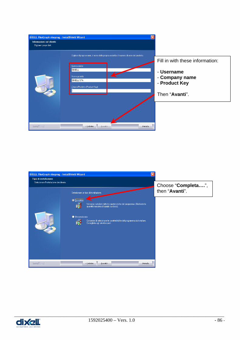
11. VISOPROG INSTALLATION AND SET-UP 11.1 How to install VISOPROG software
To install VISOPROG software are necessary:
• Software CD.
• To have the PRODUCT KEY (provided by Dixell)
Insert the CD in your PC and launch the program and then follow the instruction
as showed here below
Choose “Avanti”.
Choose “Accetto….”, then “Avanti”.
________________________________________________________________________________________________________ 1592025400 – Vers. 1.0 - 86 -
Fill in with these information: - Username - Company name - Product Key Then “Avanti”.
Choose “Completa….”, then “Avanti”.

________________________________________________________________________________________________________ 1592025400 – Vers. 1.0 - 87 -
Choose “Installa.”.
Now the installation is completed: choose “Fine” to close the windows

________________________________________________________________________________________________________ 1592025400 – Vers. 1.0 - 88 -
11.2 Licence Activation Start the VISOPROG program with double click on the icon in your desktop:
To complete the installation choose Utility License
In the window here below you will find the information about your Product Key and the
Installation Key (this number has been generated automatically by VISOPROG).
Now there are two ways to complete the authorization:
• : in this case you have to send the two codes (Product Key and Installation
key ) to Dixell by fax or mail to get the Activation Key.
• : in this case you can get the Activation Key automatically (an Internet
Connection is required)
From this moment you can work with VISOPROG.

________________________________________________________________________________________________________ 1592025400 – Vers. 1.0 - 89 -
11.3 How to set-up the VISOPROG program Before to set-up the program it is necessary to open a project.
In the CD you can find the project “Dixell_visoprog” that you have to copy inside the folder
“C:\Programmi\DIXELL\DIXELL VisoGraph visoprog\Template” in your computer.
Open the project copied just now:
And choose the file “Keyboard”:
Now we have to sep-up the program with some information:
• Language to use.(Environment Language)
• Connection between Visoprog and iPRO. (Environment Instrument)
• Project options (File Options)

________________________________________________________________________________________________________ 1592025400 – Vers. 1.0 - 90 -
11.3.1 Environment Language This set-up defines the language used in your environment.
Select: Environment Language and choose your preferred language.
Pay attention because if your language is not included in the standard languages, you can
add it for yourself. Go inside the folder “Languages” that you can find in your default
installation directory.
For example, starting from Italian file, we have copied and renamed it in German file.
At this point, you can edit and modify the file translating the text into your language.
Save the file and, at the next starting of VISOPROG, you will be able to select your
language.

________________________________________________________________________________________________________ 1592025400 – Vers. 1.0 - 91 -
11.3.2 Environment Connection This set-up defines the connection between your personal computer and the iPRO.
Select: Environment Instrument and choose the iPRO device.
11.3.3 Project Options This set-up defines all the options of your project.
Select: File Options.
In these window there are the information about the name of developer, the baud rate (the speed communication between the VISOGRAPH and iPRO) and the description of your project.

________________________________________________________________________________________________________ 1592025400 – Vers. 1.0 - 92 -
In this window you can define the fonts of your project; for each project you can choose 4
fonts. In every moment you can change the fonts (click on Edit and choose the new one),
but pay attention that in your project the previous font will be updated automatically with the
new one.
In this window you can define the languages to use in your user interface. For each project
you can use up to 5 languages and this file can be manage as an excel file.
________________________________________________________________________________________________________ 1592025400 – Vers. 1.0 - 93 -
To create and manage your vocabulary in the best way please follows these suggestions:
• Define the multi-languages to use in your project.
Click this icon and choose the languages to add.
• Define the language to use (this is the language that you will see in VISOPROG
during the developing of your project); if you want, in every moment, it is possible to
change it to check the others languages in your display.
Click this icon and choose the default language.
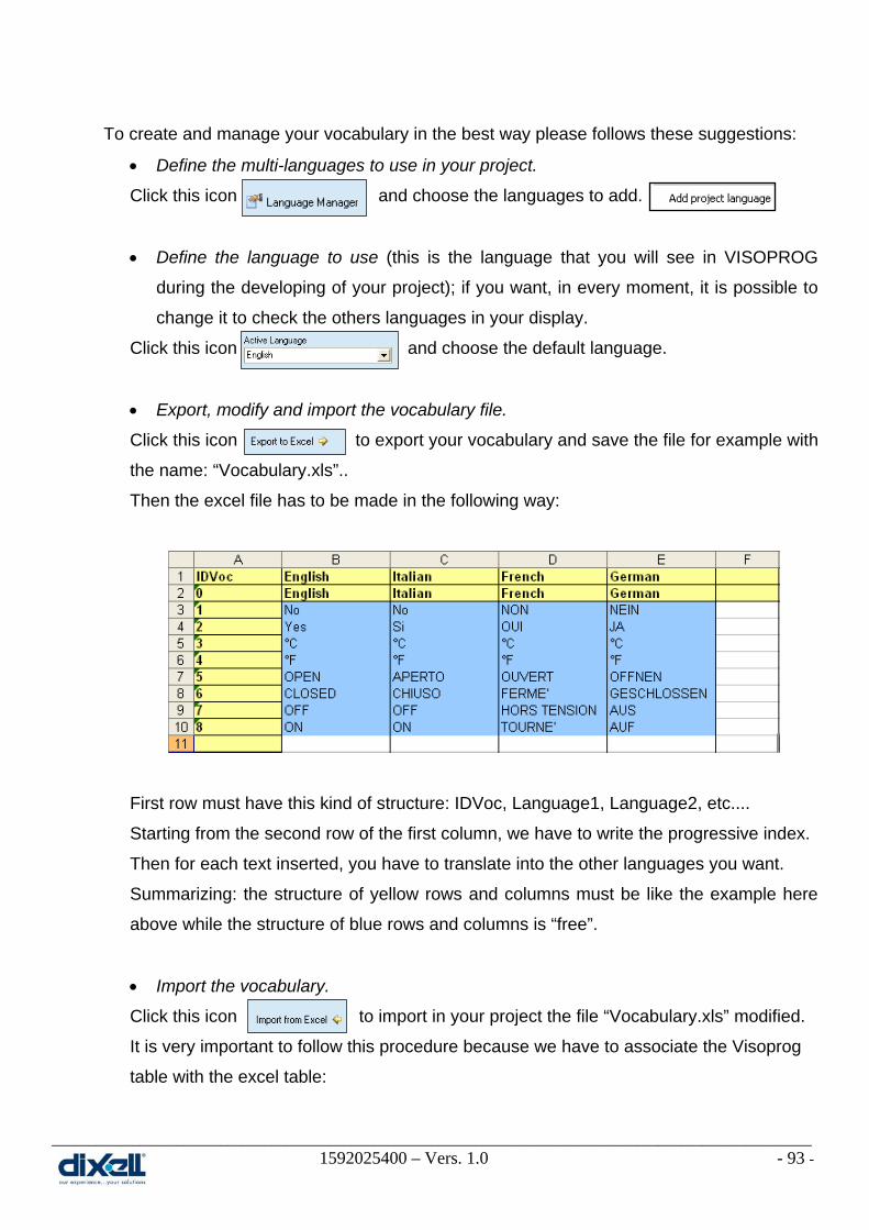
• Export, modify and import the vocabulary file.
Click this icon to export your vocabulary and save the file for example with
the name: “Vocabulary.xls”..
Then the excel file has to be made in the following way:
First row must have this kind of structure: IDVoc, Language1, Language2, etc....
Starting from the second row of the first column, we have to write the progressive index.
Then for each text inserted, you have to translate into the other languages you want.
Summarizing: the structure of yellow rows and columns must be like the example here
above while the structure of blue rows and columns is “free”.
• Import the vocabulary.
Click this icon to import in your project the file “Vocabulary.xls” modified.
It is very important to follow this procedure because we have to associate the Visoprog
table with the excel table:

________________________________________________________________________________________________________ 1592025400 – Vers. 1.0 - 94 -
First click on “A” , then “B”, “C”, “D” and “E”; in the left table you will see the following
structure:
Click Import and then OK to finish the procedure.
Now your vocabulary has been imported in your project.
In this window is possible to associate the variables between the ISaGRAF and VISOPROG
projects; they can Import or Export the variables each other.

________________________________________________________________________________________________________ 1592025400 – Vers. 1.0 - 95 -
• Define the ISaGRAF project to link in VISOGRAPH project.
Select the ISaGRAF project where Import and Export the variables:
• Import the Variables.
Confirm the operation.
If you click on Variables you will find the variables defined in the project “Example1”.
Now is possible to export the excel file, modify and then import the file again; in this way
is not necessary to modify the variables two times.
For VISOPROG
For ISaGRAF

________________________________________________________________________________________________________ 1592025400 – Vers. 1.0 - 96 -
In this window there are the images that is possible to use in your project.
With the buttons is possible:
Add or update the single image.
Delete, save and load the whole list of images.
Export the single image to modifies it.
The recognized formats for images are .gif, .jpg, .bmp, .ico, .emf and .wmf.
For each list is possible to manage up to 256 images.

________________________________________________________________________________________________________ 1592025400 – Vers. 1.0 - 97 -
In this window you can define the destination folder for your .bin file. The bin file is the
compiled file of your project. This is the file to download in your VISOGRAPH interface.
In this option is possible to decide which languages to add in the bin file.

________________________________________________________________________________________________________ 1592025400 – Vers. 1.0 - 98 -
12. VISOGRAPH The VISOGRAPH Human Interface is a graphic lcd display necessary to visualize all the
variables defined in the iPRO (remember that only the variables with an address defined in
the ISaGRAF project can be visualized).
The main characteristics are:
• Graphic Lcd 240x96 pixel
• 8 full programmable keys
• Multi-languages
• Processor 32bit
• 3 wires bus
• Panel and wall mounting
• Optional NTC probe on board
• Software updating from USB (through the iPRO)
The Graphic Lcd and the Keys are programmable by the user; this is possible using the
software tool VISOPROG made by Dixell.

________________________________________________________________________________________________________ 1592025400 – Vers. 1.0 - 99 -
13. THE VISOPROG WORKBENCH
13.1 Introduction The VISOPROG workbench is the environment developed by Dixell to build the human
interface in the VISOGRAPH graphic lcd.
VISOPROG reads the ISaGRAF project from the iPRO and imports directly variables and
function blocks to create automatically the basic interface; then the developer completes the
interface adding functionality through the keys.
VISOPROG can import images and multi-languages dictionary.
13.2 The VISOPROG environment The VISOPROG environment is composed by three areas:
• The STAGE area:
• The STAGE EDITOR area:
• The INFORMATION area (Object Properties, Main View, ...):
________________________________________________________________________________________________________ 1592025400 – Vers. 1.0 - 100 -
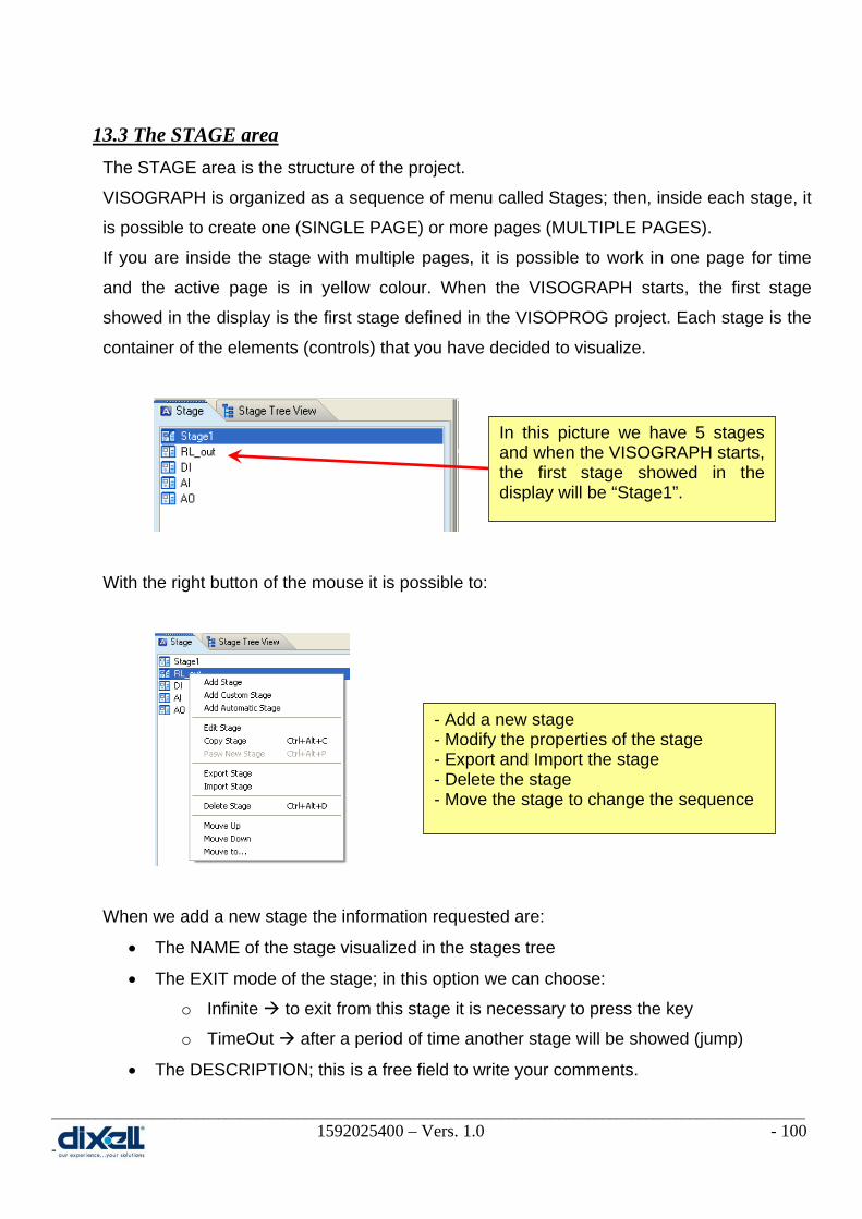
13.3 The STAGE area The STAGE area is the structure of the project.
VISOGRAPH is organized as a sequence of menu called Stages; then, inside each stage, it
is possible to create one (SINGLE PAGE) or more pages (MULTIPLE PAGES).
If you are inside the stage with multiple pages, it is possible to work in one page for time
and the active page is in yellow colour. When the VISOGRAPH starts, the first stage
showed in the display is the first stage defined in the VISOPROG project. Each stage is the
container of the elements (controls) that you have decided to visualize.
With the right button of the mouse it is possible to:
When we add a new stage the information requested are:
• The NAME of the stage visualized in the stages tree
• The EXIT mode of the stage; in this option we can choose:
o Infinite to exit from this stage it is necessary to press the key
o TimeOut after a period of time another stage will be showed (jump)
• The DESCRIPTION; this is a free field to write your comments.
In this picture we have 5 stages and when the VISOGRAPH starts, the first stage showed in the display will be “Stage1”.
- Add a new stage - Modify the properties of the stage - Export and Import the stage - Delete the stage - Move the stage to change the sequence

________________________________________________________________________________________________________ 1592025400 – Vers. 1.0 - 101 -
In the picture here below an example:
Other information available in this area are:
• Stage Tree View:
o TreeView all the Images, labels and variables used in the stage.
o Element Order the order of introduction of the elements.
Name of the stage
This configuration means that after 10 seconds from “Stage1” the display will showed the stage “AI”. Pay attention because the TimeOut period is multiple of 5 seconds.

________________________________________________________________________________________________________ 1592025400 – Vers. 1.0 - 102 -
13.4 The STAGE EDITOR area The STAGE EDITOR area is the area where to create the interface of the stage.
In this area through the control bar is possible to add labels, variables, Images and switch
variables/labels.
Inside the control bar there are five options:
VarLabel: With this control you can add the variables to visualize the value; these are the variables defined in the ISaGRAF project.
DXLabel: With this control you can add a fixed string or value; this string can be associate with the vocabulary.
DxImage: With this control you can add an image from the database.
DxAnimImage: With this control you can add an animated image; this animation is made adding images from the database.
DxSwitchVarLabel: With this control you can add an image or a label depending on the value of the variable.
For each stage it is possible to insert up to 128 controls.
To add some buttons, in this area it is enough to create the label or image; to add them in
the project is explained in the next chapter.

________________________________________________________________________________________________________ 1592025400 – Vers. 1.0 - 103 -
13.5 The INFORMATION AREA The INFORMATION AREA is the area composed by:
In this tab there are the properties of the controls, the layers of your stage and the buttons setting.
In this tab there is the preview of your stage; the possibility to export the snapshot of your stage and it is possible to write the values of the variables to simulate the real functioning.
In this tab there are the properties of the variables.
In this tab there are all the words included in your vocabulary (if in your project there are more languages, here is visualized only the active language).
In this tab we can see and manage the states used by human interface; it is possible to show in the display a label instead of the number of the variable.
13.5.1 Object Properties All the controls in VISOPROG have some properties. The properties can be modified thanks
to the Object Properties tab. The properties for the control (for example the Dixell image)
are:
• Left X it is the top left corner value, in the X coordinate, of the control.
• Top Y it is the top left corner value, in the Y coordinate, of the control.
• ScrollLock it permits to show the control in all the pages of the stage.
• Disabled if this control is enabled (property unchecked) the control has
additional properties.
• Font Number it permits to change the font.
• Layer it permits to place the control in different layer
• Visible IF it permits to change the visibility of control depending on variable
value.
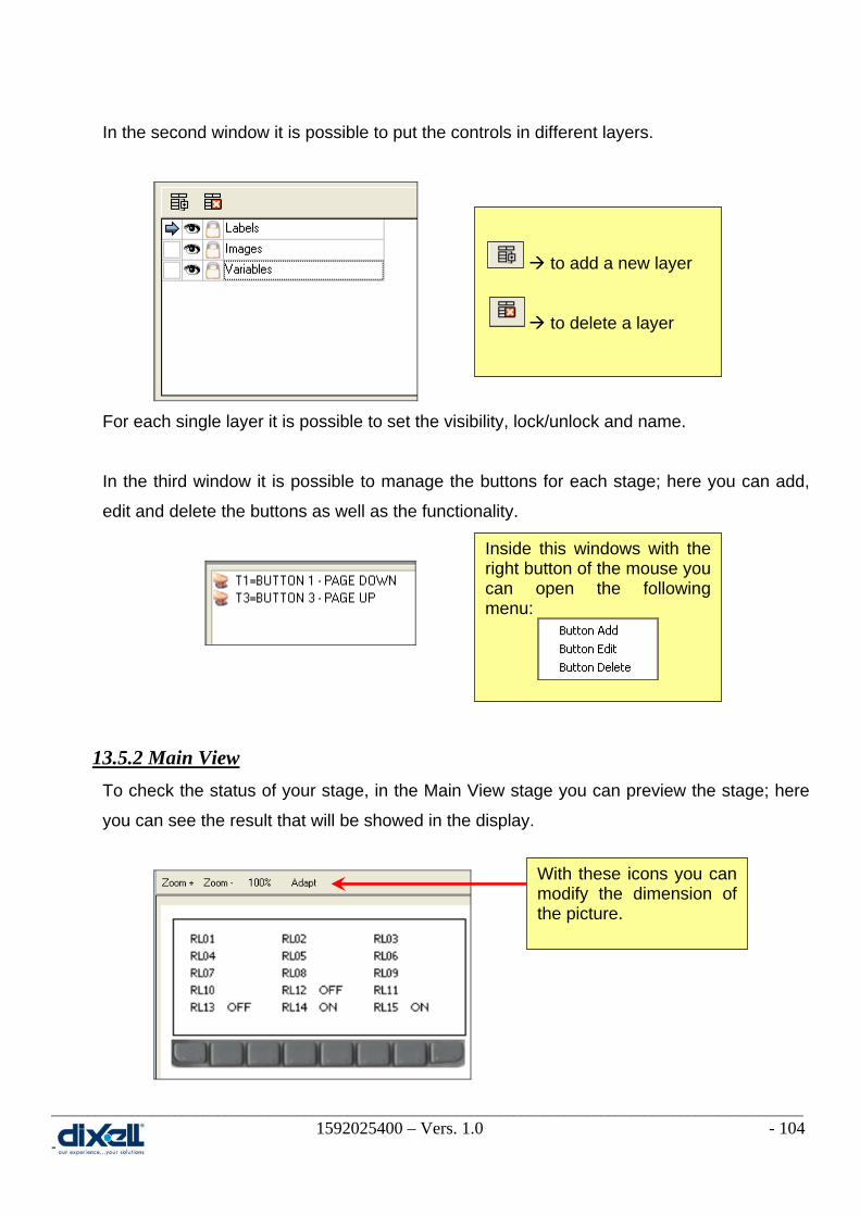
________________________________________________________________________________________________________ 1592025400 – Vers. 1.0 - 104 -
In the second window it is possible to put the controls in different layers.
For each single layer it is possible to set the visibility, lock/unlock and name.
In the third window it is possible to manage the buttons for each stage; here you can add,
edit and delete the buttons as well as the functionality.
13.5.2 Main View To check the status of your stage, in the Main View stage you can preview the stage; here
you can see the result that will be showed in the display.
to add a new layer to delete a layer
Inside this windows with the right button of the mouse you can open the following menu:
With these icons you can modify the dimension of the picture.

________________________________________________________________________________________________________ 1592025400 – Vers. 1.0 - 105 -
In the other window you can export the picture and also simulate the variables value; it is
enough to write the word or the number inside the box.
13.5.3 Variables In this tab there are the properties of the variables; here you can see and modify the
variables used in the human interface project.
The properties of the variables are:
• Address the address of the variable (defined in ISaGRAF project)
769 Hexadecimal
0301 Decimal
• Signed define if the variable is with or without sign
vtInt signed
vtUInt unsigned
Click this icon to export the picture.
All the words or numbers write here are showed in the picture above.
Here there are the properties for each variables selected in the list below.
This is the list of the variables used in the project.

________________________________________________________________________________________________________ 1592025400 – Vers. 1.0 - 106 -
• Mask pointer to state list is the variable is showed as state (active only
with “State” checked)
• Read from Excel if checked (= 1) means that previous properties cannot change.
If unchecked (= 0) the application can change them.
• LimitMax variable upper limit (only if Read from Excel = 1)
• LimitMin variable lower limit (only if Read from Excel = 1)
• Decimals number of decimals
• ReadOnly
13.5.4 Vocabulary In this tab you can see all the words defined in your vocabulary.
If in your project there are more languages, the vocabulary showed is the vocabulary
defined in the “Project Options”. In this case the active language is English.
13.5.5 View State In this tab you can see all the states used in the human interface; the syntax is:
• [number] label
When the value of your variable is 1, in the human interface will be visualized the label OPEN; when the value is 2 will be visualized CLOSE. This is possible if your variable has been set with State checked and Mask = 1.
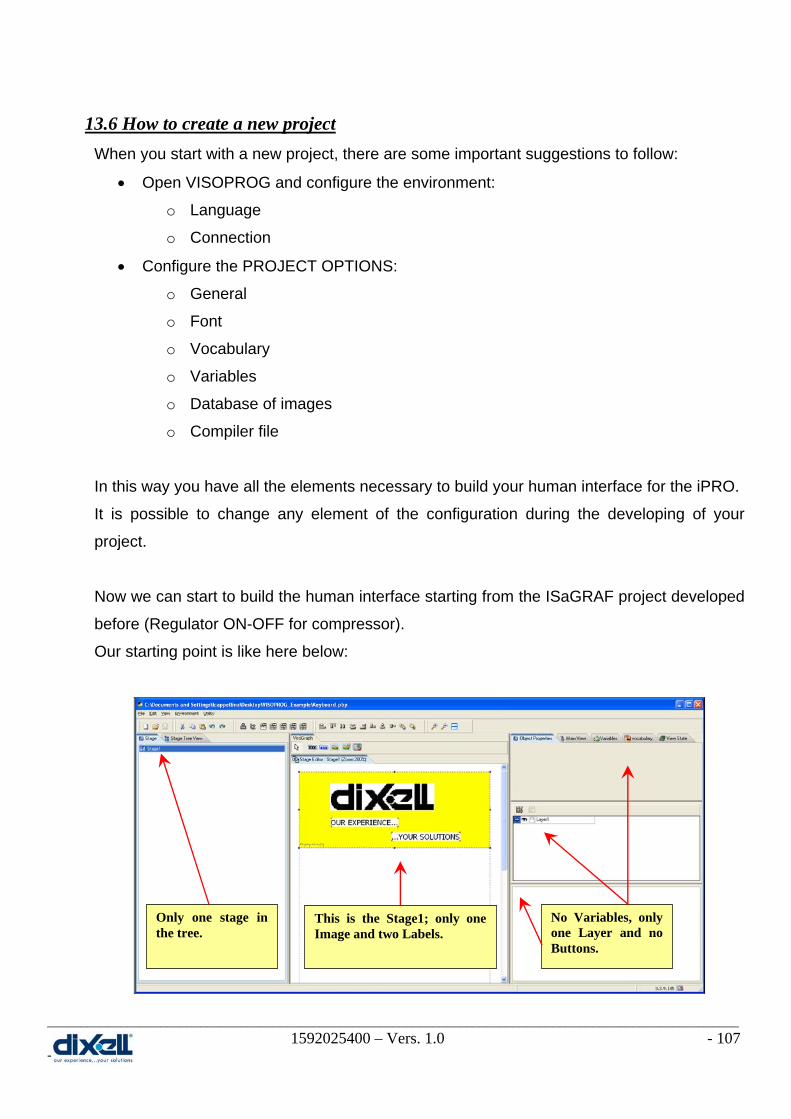
________________________________________________________________________________________________________ 1592025400 – Vers. 1.0 - 107 -
13.6 How to create a new project When you start with a new project, there are some important suggestions to follow:
• Open VISOPROG and configure the environment:
o Language
o Connection
• Configure the PROJECT OPTIONS:
o General
o Font
o Vocabulary
o Variables
o Database of images
o Compiler file
In this way you have all the elements necessary to build your human interface for the iPRO.
It is possible to change any element of the configuration during the developing of your
project.
Now we can start to build the human interface starting from the ISaGRAF project developed
before (Regulator ON-OFF for compressor).
Our starting point is like here below:
Only one stage in the tree.
This is the Stage1; only one Image and two Labels.
No Variables, only one Layer and no Buttons.

________________________________________________________________________________________________________ 1592025400 – Vers. 1.0 - 108 -
To import the variables used in ISaGRAF project choose: FILE OPTION and then
Variables & States tab (or click the icon, in the menu bar, ).
Operations to do in this section are:
• Link VISOPROG with the ISaGRAF project Isagraf Linked project
• Click on Variables & States and choose Import from Isagraf project The controls to add in our new stage are:
• AI01 the analog input of temperature
• SET set point of regulator (default value, defined in ISaGRAF, is 25°C)
• BAND hysteresis of regulator (default value, defined in ISaGRAF, is 3°C)
• RL01 digital output of compressor (relay)
With these information we can start to create a new stage with the following characteristics:
The NAME of new stage is STAGE2 The EXIT mode is INFINITE; to change stage is necessary to add some button.

________________________________________________________________________________________________________ 1592025400 – Vers. 1.0 - 109 -
and we can also modify the characteristic of the stage1:
In the Stage2 I want to visualize the temperature, the compressor status and add buttons to
change page where I can verify the set-point and hysteresis.
To visualize the temperature we have to add two labels and one variable:
Double click on “TEMPERATURE” label to define the properties:
Also for the “°C” label we have to do the same procedure.
The EXIT mode is TIMEOUT: - Timeout = 1 (is multiple of 5 seconds) - Stage = Stage2 (after 5 second the display will jump to the Stage2)
Add this Labels with .
Add this Variable with .
In this windows we have defined: - the description, in this case linked with the vocabulary. - the font.

________________________________________________________________________________________________________ 1592025400 – Vers. 1.0 - 110 -
Double click on “-XXXXXX” variable to define the properties:
To preview the result of the stage, click on “Main View” tab:
In this windows we have defined: - which variable is visualized - the sign and how many digits are visualized
To simulate some value, fill in this box. In the preview window the value will be visualized.
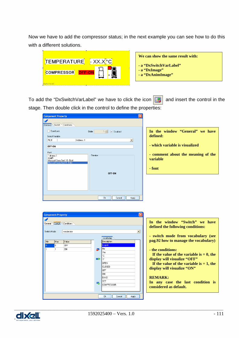
________________________________________________________________________________________________________ 1592025400 – Vers. 1.0 - 111 -
Now we have to add the compressor status; in the next example you can see how to do this
with a different solutions.
To add the “DxSwitchVarLabel” we have to click the icon and insert the control in the
stage. Then double click in the control to define the properties:
We can show the same result with: - a “DxSwitchVarLabel” - a “DxImage” - a “DxAnimImage”
In the window “General” we have defined: - which variable is visualized - comment about the meaning of the variable - font
In the window “Switch” we have defined the following conditions: - switch mode from vocabulary (see pag.92 how to manage the vocabulary) - the conditions: If the value of the variable is = 0, the display will visualize “OFF” If the value of the variable is = 1, the display will visualize “ON” REMARK: In any case the last condition is considered as default.

________________________________________________________________________________________________________ 1592025400 – Vers. 1.0 - 112 -
To add the “DxImage” we have to click the icon and insert the control in the stage.
Then double click in the control to define the properties:
Other conditions can be, for example:
• OR($4387=1,0)
If the variable $4387 is = 1, the image will be visible.
• AND($4387=1,OR($4366>0,$4370>0))
If the variable $4387 is = 1 and one variable between $4366 and $4370 are greater
than “0”, the image will be visible.
In the window “General” there is the Image database; you can choose the image that you want to visualize.
In the window “Conditions” we can define if the image is visible always or only in some condition that we can decide. In this case the image will be visible only when the compress is OFF; the condition is: OR($0001=0,0)

________________________________________________________________________________________________________ 1592025400 – Vers. 1.0 - 113 -
• To add the “DxAnimImage” we have to click the icon and insert the control in the
stage. Then double click in the control to define the properties:
Now we can check our project with the “Main View”. If we can try to write the values in the
boxes ”AI01 and RL01”, we can see the result in the display (except for the
DxSwitchVarLabel).
..... .
In the window “General” there is the Image database; you can choose the images that you want to visualize. In this case your animated image is a sequence of images.
Preview of animation.
Sequence of images from top to bottom.
Preview with: AI01 = -12.5 RL01 = 0
Preview with: AI01 = -12.5 RL01 = 1

________________________________________________________________________________________________________ 1592025400 – Vers. 1.0 - 114 -
This stage is composed of a single page; to add another page click the icon and the
second page will appear. In this new page we will add the set-point and the hysteresis; it is
clear that we have to add also some buttons to change the pages.
In the picture here above we have added four labels (SET, BAND and °C) and two
variables. The labels and the variables have been defines as in the page before.
Practically:
It is very important to pay attention to the flag “Disabled”; if the flag is checked the value is
non modifiable with the VISOGRAPH. If the flag is unchecked the value will be modifiable
through the VISOPROG buttons.
Selected the address of variable SET.
Selected the address of variable BAND.
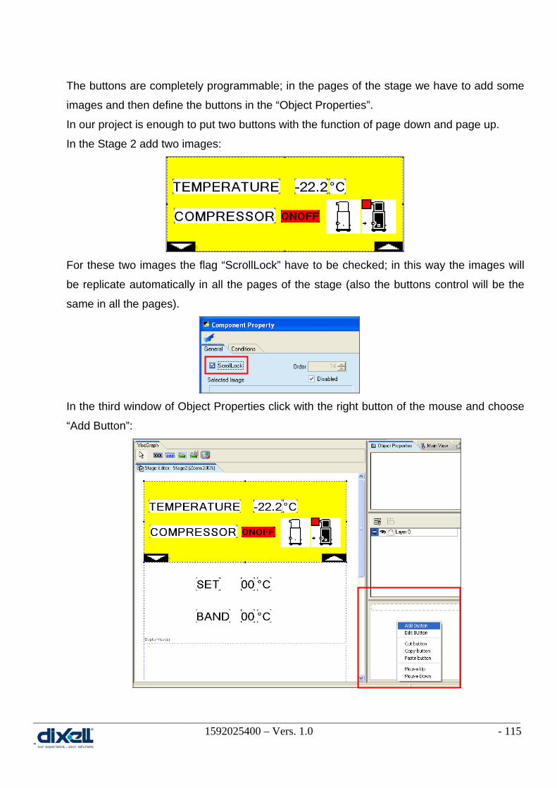
________________________________________________________________________________________________________ 1592025400 – Vers. 1.0 - 115 -
The buttons are completely programmable; in the pages of the stage we have to add some
images and then define the buttons in the “Object Properties”.
In our project is enough to put two buttons with the function of page down and page up.
In the Stage 2 add two images:
For these two images the flag “ScrollLock” have to be checked; in this way the images will
be replicate automatically in all the pages of the stage (also the buttons control will be the
same in all the pages).
In the third window of Object Properties click with the right button of the mouse and choose
“Add Button”:

________________________________________________________________________________________________________ 1592025400 – Vers. 1.0 - 116 -
The first button to define is T1.
The window here below will appear automatically and we have to set it in the following way:
To add the buttons T8 the procedure is the same but the setting is different:

________________________________________________________________________________________________________ 1592025400 – Vers. 1.0 - 117 -
After this procedure in the Object Properties there are the two buttons just created.
The project is completed so we can compile the project:
With this file you can decide to download it immediately in your VISOGRAPH (the
IPRO and the VISOGRAPH have to be connected with your PC):
Here you can under stand if your source file is OK.
This is the folder where you can find the file compiled that we have called “Compiledfile.bin” (to define the folder and name see pag. 97)
Write here the address of your IPRO.

________________________________________________________________________________________________________ 1592025400 – Vers. 1.0 - 118 -
The other way is to copy this file in the USB key to download it inside the IPRO (in this
second case it is necessary to use the function block “UPDATE_VISOGRAPH”).
13.6.1 Fine tuning of your project After the download we can see in our VISOGRAPH that there are some things to modify.
The temperature value is without decimal point:
In the display is showed 265 °C instead of 26.5 °C.
The same problem there is for the SET and BAND.
The images for UP and DOWN page are not necessary in both pages (Stage2).
In the first page is enough the DOWN page.
In the second page is enough the UP page.
The values of SET and BAND are not modifiable.
It is necessary to have the possibility to modify them.
• Decimal Point
Open your project and choose the Stage2; select the variable to modify in the page and, in
the” Variables Properties” tab, write the number of decimals in the box “Decimals. In our
case the value will be “1”. This procedure is the same for all the other variables with decimal
point.
If the download is correct you will find the following messages.
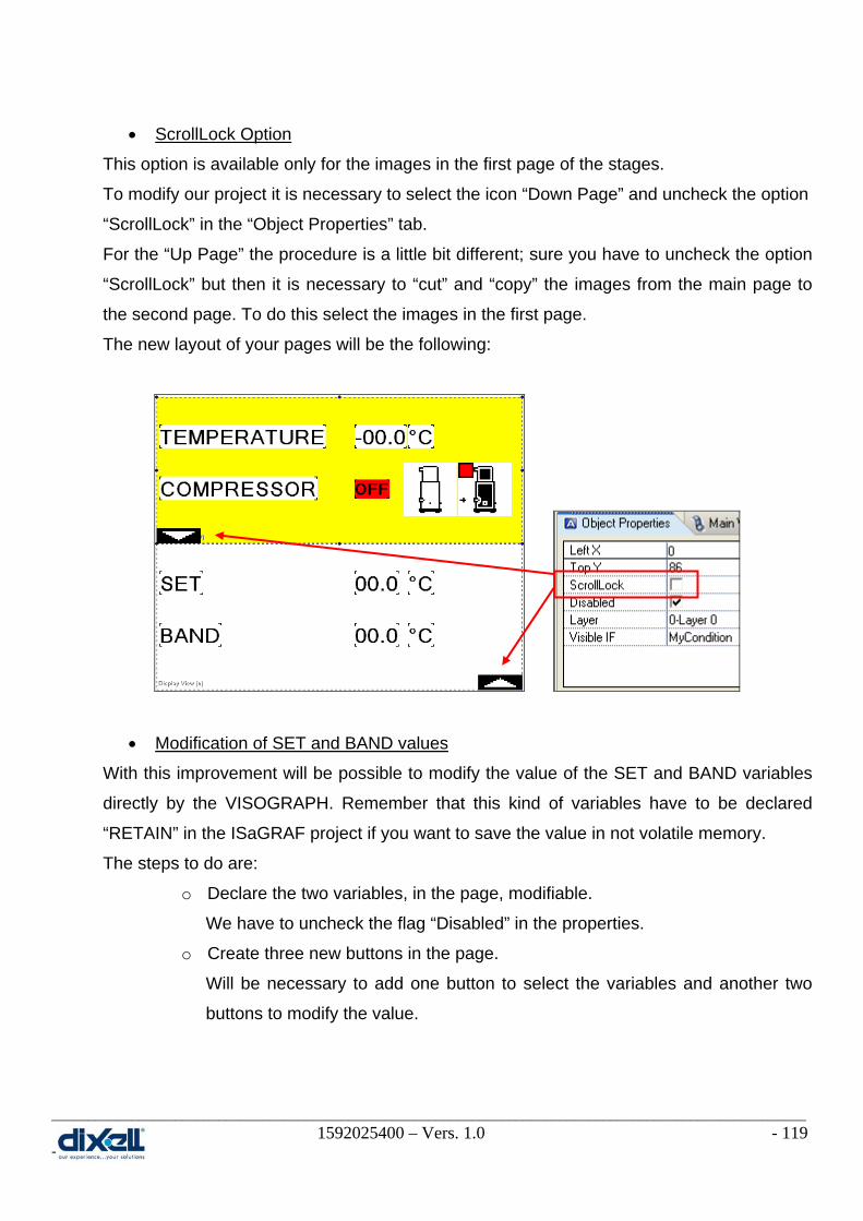
________________________________________________________________________________________________________ 1592025400 – Vers. 1.0 - 119 -
• ScrollLock Option
This option is available only for the images in the first page of the stages.
To modify our project it is necessary to select the icon “Down Page” and uncheck the option
“ScrollLock” in the “Object Properties” tab.
For the “Up Page” the procedure is a little bit different; sure you have to uncheck the option
“ScrollLock” but then it is necessary to “cut” and “copy” the images from the main page to
the second page. To do this select the images in the first page.
The new layout of your pages will be the following:
• Modification of SET and BAND values
With this improvement will be possible to modify the value of the SET and BAND variables
directly by the VISOGRAPH. Remember that this kind of variables have to be declared
“RETAIN” in the ISaGRAF project if you want to save the value in not volatile memory.
The steps to do are:
o Declare the two variables, in the page, modifiable.
We have to uncheck the flag “Disabled” in the properties.
o Create three new buttons in the page.
Will be necessary to add one button to select the variables and another two
buttons to modify the value.

________________________________________________________________________________________________________ 1592025400 – Vers. 1.0 - 120 -
To declare the two variables as modifiable, select, one by one, the variables and in the
Object Properties uncheck the flag “Disabled”.
It is also possible to define the range limits; practically you can decide the range min and
max of your variables. Then in the VISOGRAPH you can choose the value between min
and max range. Select the variable in the page and, in the Variables properties, write the
limits:
Select the variables and uncheck the flag “Disabled”.
For the variableSET: - LimitMax = 450 - LimitMin = -50 In this case is possible to choose the value between -5°C ÷ 45°C
For the variableBAND: - LimitMax =100 - LimitMin = 0 In this case is possible to choose the value between 0°C ÷ 10°C

________________________________________________________________________________________________________ 1592025400 – Vers. 1.0 - 121 -
After this, add the new images in the page but in a new layer called “SET_BAND variables”:
The new buttons to define are T2, T4 and T6 and the properties for each of them are:
These are the new three icons for the buttons.
This is the new layer where we have added the icons; the arrow means in which layer we are working.
T2 button
T4 button
This is the time that the button must be kept pressed before to get the activation; if the value is “0” the activation will be immediately.

________________________________________________________________________________________________________ 1592025400 – Vers. 1.0 - 122 -
Our project is completed and the final VISOPROG environment is like below:
Compile and download again the project in the VISOGRAPH graphic display to check the
improvements.
T6 button

________________________________________________________________________________________________________ 1592025400 – Vers. 1.0 - 123 -
13.7 Features included In the next chapters there are more information about the buttons, the disabled property, the
controls visibility and how to create the stages automatically.
13.7.1 Buttons combination and actions It is possible to activate a command only if two ore more buttons are kept pressed together.
If the buttons T3 and T5 are kept pressed together, from the Stage2 we will jump to the
Stage1; here below the example:
Add the buttons T3 and T5. Choose, with the mouse, the buttons; the “ctrl” key of the keyboard must be kept pressed to select more buttons in one time.
Here define the button action: - jump to Stage Stage1
In the buttons area we have added the buttons combination.
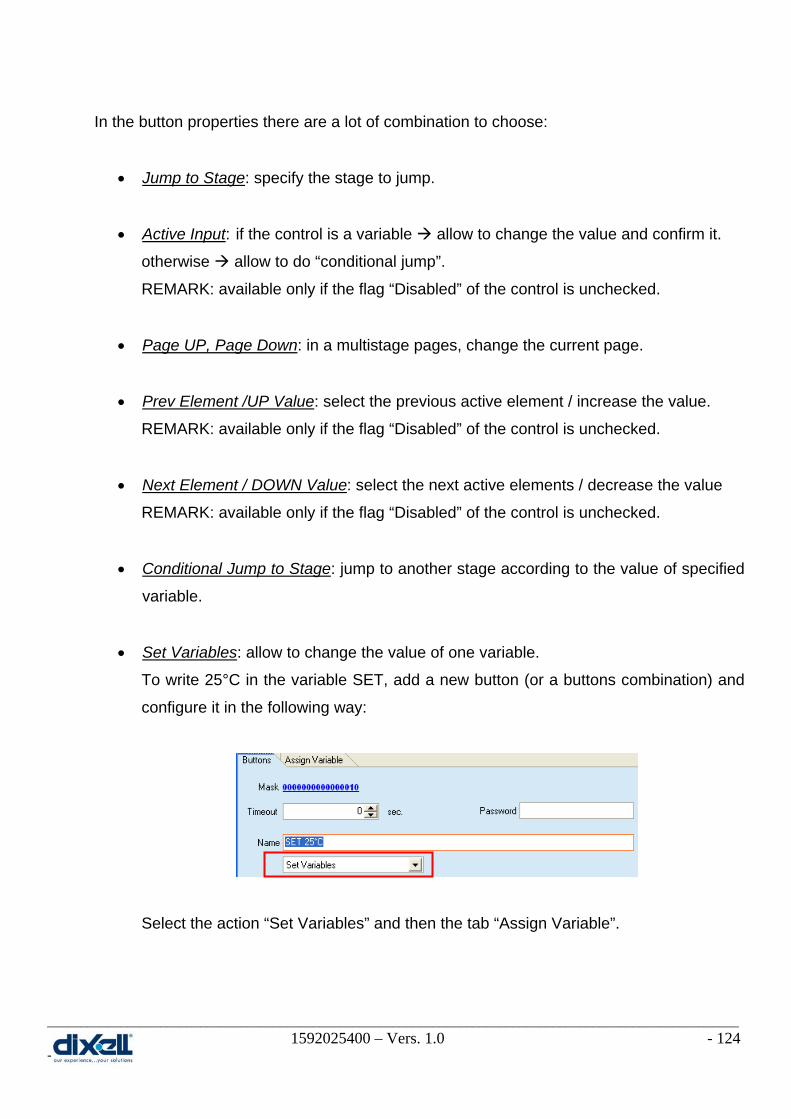
________________________________________________________________________________________________________ 1592025400 – Vers. 1.0 - 124 -
In the button properties there are a lot of combination to choose:
• Jump to Stage: specify the stage to jump.
• Active Input: if the control is a variable allow to change the value and confirm it.
otherwise allow to do “conditional jump”.
REMARK: available only if the flag “Disabled” of the control is unchecked.
• Page UP, Page Down: in a multistage pages, change the current page.
• Prev Element /UP Value: select the previous active element / increase the value.
REMARK: available only if the flag “Disabled” of the control is unchecked.
• Next Element / DOWN Value: select the next active elements / decrease the value
REMARK: available only if the flag “Disabled” of the control is unchecked.
• Conditional Jump to Stage: jump to another stage according to the value of specified
variable.
• Set Variables: allow to change the value of one variable.
To write 25°C in the variable SET, add a new button (or a buttons combination) and
configure it in the following way:
Select the action “Set Variables” and then the tab “Assign Variable”.

________________________________________________________________________________________________________ 1592025400 – Vers. 1.0 - 125 -
Choose in which variable you need to write the value (double click in the variable)
and write the sentence that you prefer between these two structures:
WRT($SET=250) in this case we have used the label of the variable
WRT($0769=250) in this case we have used the address of the variable
If you want to change the status of the variable RL02 between “0” and “1”
(0 1 0 1...) you have to use the following sentence:
TOG($RL02) in this case we have used the label of the variable
TOG($0002) in this case we have used the address of the variable
• Fast increment value: if the control is a variable allow to increase the value without
confirmation
REMARK: available only if the flag “Disabled” of the control is unchecked.
• Fast decrement value: if the control is a variable allow to decrease the value
without confirmation
REMARK: available only if the flag “Disabled” of the control is unchecked.

________________________________________________________________________________________________________ 1592025400 – Vers. 1.0 - 126 -
• Jump to stage and back: allow to come back to the previous stage.
13.7.2 Disabled property unchecked (active element) As already seen in the previous example, if the flag “Disabled” is unchecked:
• for a VARIABLES: the value is modifiable.
In the stage are necessary three buttons: Active Input, UP Value and DOWN value.
• for a LABEL and IMAGE: allow to do a conditional jump stage.
In the stage are necessary three buttons: Active Input, Next Element and Prev
Element.
• for a SWITCH VAR and LABEL: enable only if switch mode is different from variable.
In this case the value of the variable is showed as images or vocabulary.
In the stage are necessary three buttons: Active Input, UP Value and DOWN Value.
13.7.3 Controls visibility VISOGRAPH has the possibility to display the information depending on the variable values.
Each elements of the VISOGRAPH human interface has the property of visibility; this
property can be filled with a mathematical (logical) condition in order to create a
dependency on a variable.
For example if the compressor is “OFF”, the control is blinking:
Inthe Component Property of the control, in the Conditions tab, the condition to write is: OR($RL01=0,0):0R($RL01=0,0) If the condition befor colon is true, the component will be visible; if the condition after the colon is true, the component, if visible, will blink.

________________________________________________________________________________________________________ 1592025400 – Vers. 1.0 - 127 -
13.7.4 Automatic Stages The automatic stage is a procedure that will help you to create one or more stage quickly.
It is no more necessary to add the controls one by one but all together in one time.
In this window you can decide which controls add in the stage, the positioning in the human
interface and the preview of the stage.
When you confirm the setting, your stage will be created automatically.
Here below the example.
Choose Add Automatic Stage.
Here there are the controls that you want to add.
Here you can define the positioning in the stage/pages and the Font.
This is the preview of your stage/pages.

________________________________________________________________________________________________________ 1592025400 – Vers. 1.0 - 128 -
The Stage3 is the new stage just now created as “AUTOMATIC STAGE”.
These are the two pages of the new stage.

________________________________________________________________________________________________________ 1592025400 – Vers. 1.0 - 129 -
14. CONNECTIVITY
14.1 Ethernet 10/100 and Serial bus In the table here below is summarizing the property for each kind of connections.
All these connections can be used all together but it is very important to understand which of
them is better for your installation.
Your decisions have to be taken considering, at least, these elements:
• Speed
• Number of nodes
• External hardware
• Protocol
The typical configuration is:
1. IPRO with XWEB RS485 slave
2. IPRO with a network of Dixell devices RS485 master

________________________________________________________________________________________________________ 1592025400 – Vers. 1.0 - 130 -
3. IPRO with I/O expansion and/or electronic valve modules CAN
4. IPRO with IPRO Ethernet
14.2 How to configure the bus and variables Before to start with the configuration, there are some information to take in consideration:
• Only DINT and BOOL variables can be read and write through the bus.
• The total number of variables that iPRO can exchange through the buses depends on
ISaGRAF USB Key (128, 256 or unlimited I/O).
• An external gateway (for example “anybus communicator”) can be used for different
protocols from Modbus (LonWorks, BACNet and Profibus).
To configure the bus, click the icon I/O Wiring ; at the first time the situation of the I/O
Wiring is the following (default configuration for iPRO):

________________________________________________________________________________________________________ 1592025400 – Vers. 1.0 - 131 -
The meaning of these I/O is:
• DIX_IO_GENLINE boards to configure the bus (MDB, ETH, CAN)
• DIX_IO_GENDI boards to configure Digital Inputs
• DIX_IO_GENDO boards to configure Digital Outputs
• DIX_IO_GENAI boards to configure Analogs Inputs
• DIX_IO_GENAO boards to configure Analogs Outputs
For example, I need to connect (through the RS485 Master) the iPRO with the Dixell device
“XT” to control the temperature of its probe.
The steps, necessary to do this are:
1. define the BUS (declare the GENLINE and its properties)
2. define the new board (declare the GENDI or GENDO or GENAI or GENAO)
3. define the new variables in the dictionary
4. assign the link between the variables and boards
14.2.1 Define the BUS (GENLINE board) To add a new board GENLINE, click the icon and fill in the following table:

________________________________________________________________________________________________________ 1592025400 – Vers. 1.0 - 132 -
Then confirm and the new board will be added in your project.
Double click on “Parameters” to configure the GENLINE board.
To complete the configuration, confirm with “OK” and save .
This is the new board to add.
This is the board number and the number increase automatically.

________________________________________________________________________________________________________ 1592025400 – Vers. 1.0 - 133 -
The meaning of these parameters is:
Some information about the GENLINE board:
• it is possible to define only one GENLINE with name MDB.
• max baud-rate is 19200 (par_5).
• do not change the “fixed strings” (name and par_4).
• the iPRO with GENLINE MDB is MASTER.
It can read and write variables from slaves.
The other Buses are the ETHERNET and CAN; the configurable tables for these buses are:

________________________________________________________________________________________________________ 1592025400 – Vers. 1.0 - 134 -
Some information about the ETH and CAN boards:
• it is possible to define more than one GENLINE with name ETH and CAN.
• do not change the “fixed string” (name).
14.2.2 Define the I/O (GENAI, GENAO, GENDI, GENDO boards) To add a new I/O board, click the icon and fill in the following table:
Regarding the number of channels pay attention because:
• if the number of channels is > 1, variables needs to have a consecutive addresses.
This is the situation when your iPRO has to read 10 variables with address from 100 to
109; in this case declare one GENAI board with Number of Channels = 10.
This is the new board to add.
This is the board number and the number increase automatically.
The number of channels is a group of variables that iPRO can read and write with a single frame. For the example, we have to read only one probe so the value is 1.

________________________________________________________________________________________________________ 1592025400 – Vers. 1.0 - 135 -
• If the number of channels is > 1 but the addresses are not consecutive, will be
necessary to define different boards.
This is the situation when your iPRO has to read 3 variables with address 100, 101
and 104; in this case declare two GENAI: the first to read the variables with address
100 and 101 (the Number of Channels = 2), the second to read the variable with
address 104 (Number of Channels = 1).
Then confirm and the new board will be added in your project.
Double click on “Parameters” to configure the GENAI board.
To complete the configuration, confirm with “OK” and save .

________________________________________________________________________________________________________ 1592025400 – Vers. 1.0 - 136 -
The meaning of these parameters is:
Some information about the GENAI, GENAO, GENDI and GENDO boards of MDB:
• if par_2 and/or par_3 are names of variables, ISaGRAF application can change node
and variable address to read and write.
Some information about the GENAI, GENAO, GENDI and GENDO boards of ETH:
• if par_3 is a name of variable, ISaGRAF application can change node and variable
address to read and write 0x var hex.

________________________________________________________________________________________________________ 1592025400 – Vers. 1.0 - 137 -
14.2.3 Define the new variable(s) in the dictionary The new I/O has to be defined in the dictionary; it is necessary to add the new variable(s) in a
new or existing group of variables.
In our example we have to add the variable AI11; for this variable (and in any case for each
variable), it is important to declare:
• Name
• Type
• Direction
• Attribute

________________________________________________________________________________________________________ 1592025400 – Vers. 1.0 - 138 -
14.2.4 Link between variables and boards The last operation to do is link the new variable(s) with the new boards.
To complete our example, it is clear that we have to link the variable AI11 with the GENAI
board.
Click the icon to open the I/O window.
Click on the last GENAI board; in the Unwired variables (in the right side of the window) is
visible the variable AI11.
To link the variable with the board, select the “ID point” in the board:
and then double click on the variable AI11.
From the unwired variables the AI11 will disappear and the description in the GENAI ID point
will become:
Now save, compile and download the application in your iPRO.
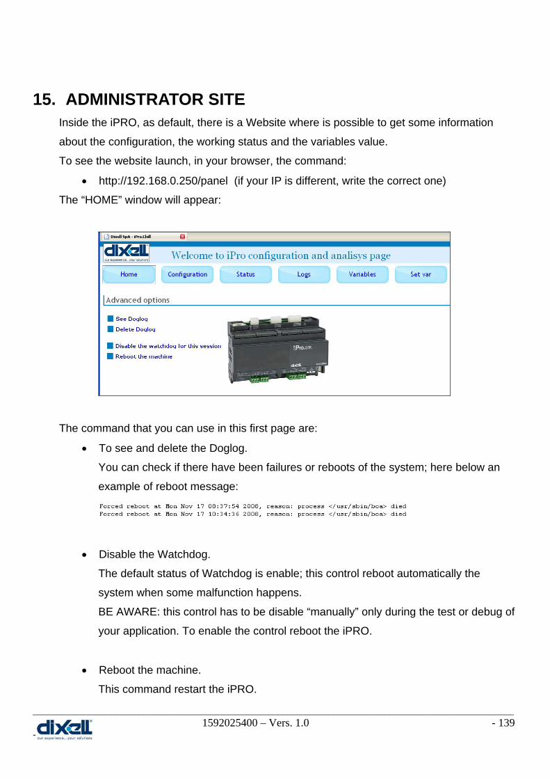
________________________________________________________________________________________________________ 1592025400 – Vers. 1.0 - 139 -
15. ADMINISTRATOR SITE Inside the iPRO, as default, there is a Website where is possible to get some information
about the configuration, the working status and the variables value.
To see the website launch, in your browser, the command:
• http://192.168.0.250/panel (if your IP is different, write the correct one)
The “HOME” window will appear:
The command that you can use in this first page are:
• To see and delete the Doglog.
You can check if there have been failures or reboots of the system; here below an
example of reboot message:
• Disable the Watchdog.
The default status of Watchdog is enable; this control reboot automatically the
system when some malfunction happens.
BE AWARE: this control has to be disable “manually” only during the test or debug of
your application. To enable the control reboot the iPRO.
• Reboot the machine.
This command restart the iPRO.

________________________________________________________________________________________________________ 1592025400 – Vers. 1.0 - 140 -
Click on “CONFIGURATION” to check and change the net configuration.
Click on “STATUS” to check the system status.
Click on “LOGS” to check and download the log files (for example the alarms file).

________________________________________________________________________________________________________ 1592025400 – Vers. 1.0 - 141 -
Click on “VARIABLES” to check the information about the variables used in your application.
Click on “SET VAR” to change the value of the variables.
If you want to change the value of the variable “SET” from 100 to 150, write the name of the
variable, the new value and then confirm.