(12) United States Patent (10) Patent No.: Yamaguchi … · (73) Assignee: Nissan Motor Co., Ltd.,...
86
(12) United States Patent Yamaguchi et al. USOO6480767B2 US 6,480,767 B2 Nov. 12, 2002 (10) Patent No.: (45) Date of Patent: (54) CONTROL SYSTEM FOR HYBRID VEHICLE (75) Inventors: Musashi Yamaguchi, Kanagawa-ken (JP); Itsuro Muramoto, Kanagawa-ken (JP); Nobutaka Takahashi, Kanagawa-ken (JP) (73) Assignee: Nissan Motor Co., Ltd., Kanagawa (JP) (*) Notice: Subject to any disclaimer, the term of this patent is extended or adjusted under 35 U.S.C. 154(b) by 0 days. (21) Appl. No.: 09/957,649 (22) Filed: Sep. 21, 2001 (65) Prior Publication Data US 2002/0062183 A1 May 23, 2002 (30) Foreign Application Priority Data Sep. 22, 2000 (JP) ....................................... 2OOO-289355 Dec. 20, 2000 (JP) ....................................... 2OOO-387832 (51) Int. Cl. .................................................. G06F 7700 (52) U.S. Cl. ........................ 701/22; 701/101; 180/65.2; 180/65.3; 180/65.4; 180/165; 318/139 (58) Field of Search .................. 701/22, 101; 180/65.1, 180/65.2, 65.3, 65.4, 65.6, 65.7, 65.8, 165; 318/139, 140; 477/2, 3, 6 (56) References Cited U.S. PATENT DOCUMENTS 4,547,678 A * 10/1985 Metzner et al. ........... 290/40 C 2 GENERATOR COMBUSTION GENERATOR ENGINE CONTROLLER CONTROLLER l POWER DISTRIBUTION CONTROLLER 5,722,502 A 3/1998 Kubo ........................ 180/65.4 5,927.416 A * 7/1999 del Re et al. ....... ... 180/65.2 6,019,183 A 2/2000 Shimasaki et al. .......... 180/165 FOREIGN PATENT DOCUMENTS JP 9-98516 4/1997 * cited by examiner Primary Examiner-Gertrude Arthur (74) Attorney, Agent, or Firm-McDermott, Will & Emery (57) ABSTRACT A control System for a hybrid vehicle has a consumed electric power calculator (20), which calculates electric power consumption, and a battery State calculator (21), which calculates battery state SOC of a battery (5). Based on this battery State, a physical quantity per effective electric power calculator (25) calculates a physical quantity per effective power when electric power equal to or greater than consumed electric power is generated for various electric power consumption and electric power generation, and a threshold value calculator (22) obtains a threshold value having the same unit as that of the physical quantity per effective power using predetermined calculation for Select ing operating modes of a generator and the battery. An operating mode Selector (23) selects operating modes for an engine (1) and the battery (5) based on comparison between the above threshold value and the physical quantity per effective power corresponding to the consumed electric power, and a target generated electric power calculator (24) calculates target electric power generation. An electric power distribution controller (6) controls the engine (1) and the motor (3). 13 Claims, 54 Drawing Sheets 3 MECHANCAL LINKAGE ELECTRICAL CONNECTION FLOW OF CONTROL SIGNALS SGNAL INPUT
Transcript of (12) United States Patent (10) Patent No.: Yamaguchi … · (73) Assignee: Nissan Motor Co., Ltd.,...
(12) United States Patent Yamaguchi et al.
USOO6480767B2
US 6,480,767 B2 Nov. 12, 2002
(10) Patent No.: (45) Date of Patent:
(54) CONTROL SYSTEM FOR HYBRID VEHICLE
(75) Inventors: Musashi Yamaguchi, Kanagawa-ken (JP); Itsuro Muramoto, Kanagawa-ken (JP); Nobutaka Takahashi, Kanagawa-ken (JP)
(73) Assignee: Nissan Motor Co., Ltd., Kanagawa (JP)
(*) Notice: Subject to any disclaimer, the term of this patent is extended or adjusted under 35 U.S.C. 154(b) by 0 days.
(21) Appl. No.: 09/957,649 (22) Filed: Sep. 21, 2001 (65) Prior Publication Data
US 2002/0062183 A1 May 23, 2002 (30) Foreign Application Priority Data Sep. 22, 2000 (JP) ....................................... 2OOO-289355 Dec. 20, 2000 (JP) ....................................... 2OOO-387832
(51) Int. Cl. .................................................. G06F 7700 (52) U.S. Cl. ........................ 701/22; 701/101; 180/65.2;
180/65.3; 180/65.4; 180/165; 318/139 (58) Field of Search .................. 701/22, 101; 180/65.1,
180/65.2, 65.3, 65.4, 65.6, 65.7, 65.8, 165; 318/139, 140; 477/2, 3, 6
(56) References Cited
U.S. PATENT DOCUMENTS
4,547,678 A * 10/1985 Metzner et al. ........... 290/40 C
2
GENERATOR
COMBUSTION GENERATOR ENGINE CONTROLLER
CONTROLLER
l POWER
DISTRIBUTION CONTROLLER
5,722,502 A 3/1998 Kubo ........................ 180/65.4 5,927.416 A * 7/1999 del Re et al. ....... ... 180/65.2 6,019,183 A 2/2000 Shimasaki et al. .......... 180/165
FOREIGN PATENT DOCUMENTS
JP 9-98516 4/1997
* cited by examiner Primary Examiner-Gertrude Arthur (74) Attorney, Agent, or Firm-McDermott, Will & Emery (57) ABSTRACT
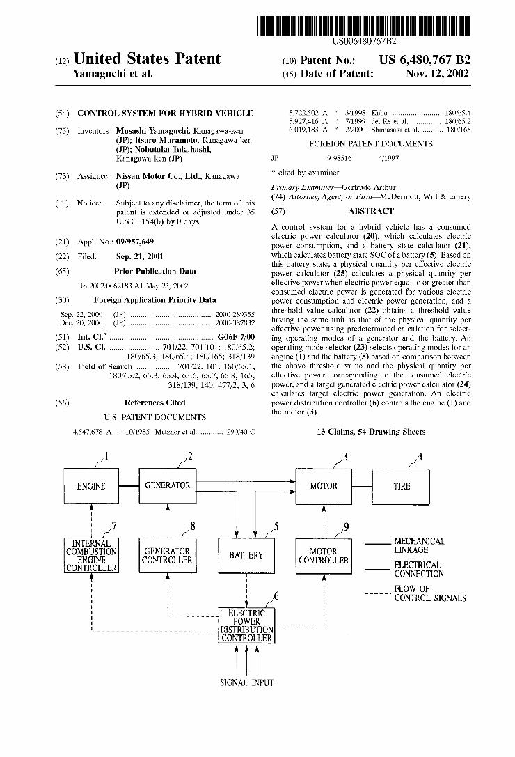
A control System for a hybrid vehicle has a consumed electric power calculator (20), which calculates electric power consumption, and a battery State calculator (21), which calculates battery state SOC of a battery (5). Based on this battery State, a physical quantity per effective electric power calculator (25) calculates a physical quantity per effective power when electric power equal to or greater than consumed electric power is generated for various electric power consumption and electric power generation, and a threshold value calculator (22) obtains a threshold value having the same unit as that of the physical quantity per effective power using predetermined calculation for Select ing operating modes of a generator and the battery. An operating mode Selector (23) selects operating modes for an engine (1) and the battery (5) based on comparison between the above threshold value and the physical quantity per effective power corresponding to the consumed electric power, and a target generated electric power calculator (24) calculates target electric power generation. An electric power distribution controller (6) controls the engine (1) and the motor (3).
13 Claims, 54 Drawing Sheets
3
MECHANCAL LINKAGE
ELECTRICAL CONNECTION
FLOW OF CONTROL SIGNALS
SGNAL INPUT

US 6,480,767 B2 Sheet 1 of 54 Nov. 12, 2002 U.S. Patent
STWNOIS TOMÉNOO HO NAOTH NOILORNNOD TWOTHILOHTA £{0WXNIT TVO?NVHOSHWN \{HTTORII NOO HOLOW
JL[\d|NI TIVNO (S \{HTTOMI NOO
NO[JL£T£IYILSIGIË - - - - - - - - - - - - - - - - - - - - - - - - - -
\{HTTIOHINOC) {{NIONEI TWNYHOEIJANI }{{{TITIONALNO)

U.S. Patent Nov. 12, 2002 Sheet 3 of 54 US 6,480,767 B2
FIG 3 REGION I : INTERNAL COMBUSTION ENGINE, GENERATOR STOP BATTERY : DISCHARGE
EFFECTIVE FUEL REGION II: 2 CONSUMPTION RATE SENSG)SOMETION ENGINE,
d V - CURVE DURING BATTERY : CHARGE s DIRECT ELECTRIC REGION II: W Poyr DISTRIBUTION | NENACOMBUSTION ENGINE. 3s GENERATOR: DRIVE t REGION I BATTERY : DISCHARGE
REGION II REGION II T
a C2 Cl
4. THRESHOLD : VALUE
A B ELECTRIC POWER CONSUMPTION IW)
SELECT OPERATION MODE
FIG.4 EFFECTIVE FUFL CONSUMPTION RATE CURVE DIRECT ELECTRIC POWER
2. ising CT DURING C3 S SURPLUS H F5SSC SMALLER s '6REATER 2. SMALLER -1N
8. t t GREATER g / C2 5 THRESHOLD
VALUE
T
COMMAND ELECTRIC POWER (W) TARGET GENERATED ELECTRIC POWER (REGION I )
U.S. Patent Nov. 12, 2002 Sheet 4 of 54 US 6,480,767 B2
FIG.5 EFFECTIVE FUEL CONSUMPTION RATE CURVE DIRECT ELECTRIC POWER DISTRIBUTION C DURING
25 C3 m SURPLUS s FSSC SMALLER
R 2- Cor?.ATER 23 3S SMALLER ELRCTRIC POWER s CONSUMPTION
E. GREATER C2
H O THRESHOLD
i VALUE s D CHARGED
- ELECTRIC POWER
ELECTRIC POWER Pn PC CONSUMPTION COMMAND ELECTRIC POWER (W)
TARGET GENERATED ELECTRIC POWER (REGION II)
FIG.6 EFFECTIVE FUEL CONSUMPTION RATE CURVR DIRECT ELECTRIC POWER
host C1 DURING C3 SURPLUS ELECTRIC SMALLER POWER 'GREATER by
SMALLER ELECTRIC POWER
95. GREATER
2. THRESHOLD VALUE
GENERATED ELECTRC POWER ( ) DISCHARGED ELECTRIC POWER l
COMMAND ELECTRIC POWER (W TARGET GENERATED ELECTRIC POWER (REGION II)

U.S. Patent Nov. 12, 2002 Sheet S of 54 US 6,480,767 B2
FIG.7
Sl READ RUNNING STATE SIGNAL
CALCULATE S2 BATTERY STATE
CALCULATE FLECTRIC S3 POWER CONSUMPTION
CALCULATE PHYSICAL S4 QUANTITY PER EFFECTIVE
ELECTRIC POWER
CALCULATE THRESHOLD S5 VALUE
SELECT OPERATING S6 MODE
CALCULATE S7 TARGET GENERATED ELECTRIC POWER
END

U.S. Patent Nov. 12, 2002 Sheet 6 of 54 US 6,480,767 B2
FIG.8
CALCULATE BATTERY STATE
CALCULATE STATE OF CHARGE SOC
CALCU ATF CHARGING EFFICIENCY T c AND DISCHARGING EFFICIENCY d
RETURN
S2
Sl
S12
FIG.9
CALCULATE ELECTRIC POWER CONSUMPTION
CALCULATE TARGET DRIVING TORQUE Ta
CALCULATE MOTOR EFFICIENCY Tim
S3
S2I
S22
CALCULATE ELECTRIC POWER Pn
CONSUMPTION
RETURN
S23
U.S. Patent Nov. 12, 2002 Sheet 7 of 54 US 6,480,767 B2
FIGO
CALCULATF PHYSICAL QUANTITY PER EFFECTIVE
ELECTRIC POWER
CALCULATE EFFECTIVE FUEL CONSUMPTION RATE
S4
S3
FIG 11
CALCULATE THRESHOLD VALUE
SS
Vcid = Vc S41
CALCULATE THRESHOLD VALUE Vc
RETURN
S42
U.S. Patent Nov. 12, 2002 Sheet 8 of 54 US 6,480,767 B2
FIG. 12
SELECT S6 OPERATING MODE
CALCULATE S51 OPERATING MODE REGION
S52 OTHER THAN
solic REGON I S54
REGION I OTHER THAN REGION II
REGION II S53
FIRST SECOND OPERATING MODE OPERATING MODE
S56
THIRD OPERATING MODE
RETURN
U.S. Patent Nov. 12, 2002 Sheet 9 of 54 US 6,480,767 B2
FIG.13 S7 CALCULATE
TARGET GENERATED ELECTRIC POWER
S61 OTHER THAN REGION I.
S63 REGION I OTHER THAN
REGION II
S65
CALCULATE TARGET CALCULATE TARGET GENERATED GENERATED ELECTRIC ELECTRIC POWER tFg POWER (Pg
SET TARGET GENERATED ELECTRIC
POWER (Pg TO O
CALCULATE S66 OPERATING POINT
RETURN

U.S. Patent Nov. 12, 2002 Sheet 10 of 54 US 6,480,767 B2
FIG.4 MINIMUM FUEL
CONSUMPTION RATE
E 4. r D Cy A4 O -
RPM SPEED (rpm) FUEL CONSUMPTION RATE CHARACTERISTIC
FIG 15
2 6 a r
(Ng al tTG1 Amr
:
VSP1
VSP kI/h) TARGET DRVNG FORCE MAP

U.S. Patent Nov. 12, 2002 Sheet 11 of 54 US 6,480,767 B2
FIG 16
Todd
NIn NIn rpm)
MOTOR EFFICIENCY MAP
FIG 7 tPll
EQUAL ELECTRIC POWER CONSUMPTION
CURVE
tRg Pg (W)
EFFECTIVE FUEL CONSUMPTION RATE MAP
U.S. Patent Nov. 12, 2002 Sheet 12 of 54 US 6,480,767 B2
FIG. 8
tTe Ipm)
Ne rpn) OPERATING POINT MAP
MAXIMUM EFFICIENCY FG. 9 POWER ELECTRIC
GENERATING LINE
Cl EQUAL Cl2 FECTRICPOWER CURvE 3 1 CONSUMPTION O
s CURVE CURVE 8 LOW P
1, 2 P 85 EFFICIENCY ir Y-C 3
2 THRESHOLD U VALUE
HIGH > (33
I 1.-- YCURVE AT REQUIRED t OUTPUT OCCURRENCE INTERNAL COMBUSTION ENGINE OUTPUT
(GENERATED ELECTRIC POWER) (w

U.S. Patent Nov. 12, 2002 Sheet 13 of 54 US 6,480,767 B2
FIG2O MAXIMUM Vca
PERMISSIBLE - - - - VALUE
A - 5 as 3.
: POSSIBLE v. MINIMUM Y VALUE
s
MINIMUM MAXIMUM PERMISSIBLE PERMISSIBLE
VALUE SOC (%) VALUE
GRAPH SHOWING RELATIONSHIP BETWEEN SOC AND THRESHOLD VALUE
FIG.2 MAXIMUM Vc PERMISSIBLE Y' VALUE t
As c. 3 it i? ig D
POSSIBLE Ivci MINIMUM VALUE
MINIMUM MAXIMUM PERMISSIBLE PERMISSIBLE
VALUE VALUE
VOLTAGE BETWEEN TERMINALS (V) GRAPH SHOWING RELATIONSHIP BETWEEN VOLTAGE BETWEEN TERMINALS AND THRESHOLD VALUE
U.S. Patent Nov. 12, 2002 Sheet 14 of 54 US 6,480,767 B2
MAXIMUM Vc PERMISSIBLE YE VALUE
POSSIBLE MINIMUM VALUE
MINIMUM MAXIMUM PERMISSIBLE PERMISSIBLE
VALUE VALUE
INTERNAL RESISTANCE (92) GRAPH SHOWING RELATIONSHIP BETWEEN INTERNAL
RESISTANCE AND THRESHOLD VALUE
MAXIMUM Vca FG-23 PERMISSIBLE - - -
VALUE
- D
POSSIBLE v. MINIMUM Ill VALUE
MINIMUM MAXIMUM PERMISSIBLE PERMISSIBLE
VALUE VALUE SOC (%) A
GRAPH SHOWING RELATIONSHIP BETWEEN SOC AND THRESHOLD VALUE

U.S. Patent Nov. 12, 2002 Sheet 16 of 54 US 6,480,767 B2
FIG.25
MAXIMUM Vca 62 PERMISSIBLE - - - -
VALUE
A 2.
O 9
g POSSIBLE r
MINIMUM -- '' VALUE
S
MINIMUM MAXIMUM PERMISSIBLE PERMISSIBLE
VALUE VALUE SOC (%)
GRAPH SHOWING RELATIONSHIP BETWEEN SOC AND THRESHOLD VALUE


US 6,480,767 B2 Sheet 19 of 54 Nov. 12, 2002 U.S. Patent
{{NITI TIO?! LNO) — 8INITI HENAOd DIHJLOATH ----- HIVA NOISSIWSNWHL_ {0}{0\{ TWO IN WHO?HWN
U.S. Patent Nov. 12, 2002 Sheet 20 0f 54 US 6,480,767 B2
FIG.29
DETECTER wo
116
CONTINUOUSLY VARIABLE TARGET OUTPUT 7
TRANSMISSION SHAFT POWER TRANSMITTING CALCULATOR EFFICIENCY CALCULATOR
18
CALCULATOR FOR THRESHOLD 19 PHYSSASEANTITY VALUE CALCULATOR POWER AT REOUIRED POWER OCCURRENCE
2.
STATE POWER DECDER COMPARATOR
OPERATING 122 MODE SELECTOR
TARGET UNIT OPERATINGPSiNT -l 23 CALCULATOR
24 25 26 27 N N. 41 41
CONTNUOUSLY VARABLE CLUTCH
CONTROLLER TRANSMISSION CONTROLLER CONTROLLER
ENGINE CONTROLLER

U.S. Patent Nov. 12, 2002 Sheet 21 of 54 US 6,480,767 B2
FIG.30
CURVE AT REQUIRED POWER OCCURRENCE Cbl
REGION I REGION DI
Cb2 4. THRESHOLD
: VALUE
A B COMMAND POWER (W)
FIG.3 EFFECTIVE FUE CONSUMPTION RATE CURVE AT REQUIRED
3 POWER OCCURRENCE Cb1
s suRPLUs PoweR OF S^2-, Cb3 P ENGINE M 3S T GREATER O 3 SMALLER REQUIRED POWER - L E- (NY 25 GREATER 2 /Cb2 O THRESHOD
ar VALUE
: COMMAND POWER (W)
TARGET UNIT OPERATING POINT CALCULATION (REGION I)

U.S. Patent Nov. 12, 2002 Sheet 22 of 54 US 6,480,767 B2
FIG.32
l Cb SMALLER Cb3 by2,
s As REQUIRED POWER
THRESHOLD VALUE
--
REQUIRED Pn Pd POWER COMMAND POWER (W)
TARGET UNIT OPERATING POINT CALCULATION (REGION II)
FIG.33 2. S l Cbl SMALLER
35 t3. -
s r GREATER it 5 2 Cb2 S. THRESHOLD E 2222222.7272x4:- VALUE L :::::::::::::::
- - - - - l POWER GENERATED
Pd Pl BY MOTOR
COMMAND POWER (W) TARGET UNIT OPERATING POINT CALCULATION (REGION III)

U.S. Patent Nov. 12, 2002 Sheet 23 of 54 US 6,480,767 B2
FIG.34
START
DETECT RUNNING SO1 STATE
CALCULATE TARGET SO2 OUTPUT SHAFT POWER
CALCULATE CONTINUOUSLY SO3 VARIABLE TRANSMISSION TRANSMITTING EFFICIENCY
CALCULATE PHYSICAL QUANTITY PER EFFECTIVE POWER RATE AT REQUIRED
POWER OCCURRENCE
tasis Evue - so decision state I-S106 compare power - s107
select operating mode - s108 SO9
S1 O4
CALCULATE TARGET UNIT OPERATING POINT

U.S. Patent Nov. 12, 2002 Sheet 24 of 54 US 6,480,767 B2
FIG.35
CALCULATE TARGET OUTPUT SHAFT POWER
CALCULATE TARGET DRIVING TORQUE iTd (Td=MAPLtd(VSP,acc)
S1 O2
SI 11
CALCULATE TARGET OUTPUT SHAFT POWER Pd
Pod-tTVSPI is 10/36
RETURN
S112
U.S. Patent Nov. 12, 2002 Sheet 25 0f 54 US 6,480,767 B2
FIG.36 CALCULATE PHYSICAL QUANTITY
PER EFFECTIVE POWER AT REQUIRED POWER OCCURRENCE
SO4
CALCULATE RANGE OF S21 RPM SPEED TO BE RETRIEVED
Niu-TBLcvu(VSP) NiL-TBLcvul(VSP)
S122 NiSi=Ni U,Nil J-50, NiL i=0
S123
NO S.24 CALCULATE CVT SELECT MINIMUM POINT OF
INPUT TORQUE TcvrS FUEL CONSUMPTION AMOUNT RcvtS=VSP* 10/3.6/(27tr)/60/NiSi VALUE OF OF TcvtsS-MAPicv(Td,Rcv(S,NiSL) J - MINIMUM FuelS)
S125 CALCULATION OF ENGINE
OPERATING POINT (Ten, Nen) AT REQUIRED POWER
OCCURRENCE CALCULATE
ENGINE TORQUE TeS Ten-Tes
tNen-NiS) S126 S 29
44 CACULATE
PHYSICAL QUANTITY Vn PER EFFECTIVE POWER AT
REQUIRED POWER OCCURRENCE Vn=FuelS)/(tTen Nen-27t/60)
TeSTCVS
CALCULATE ENGINE CONSUMPTION FUEL Fuel Si FuelSi-MAPfuel (TeS,NiS)
RETURN
U.S. Patent Nov. 12, 2002 Sheet 26 of 54 US 6,480,767 B2
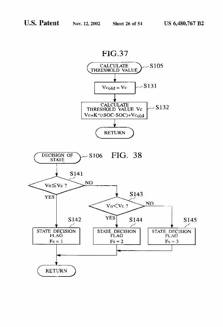
FG-37
CALCULATE THRESHOLD VALUE
S105
S131
CALCULATE THRESHOLD VALUE Vc Vc=K* (SOC-SOC)--Vcold
RETURN
S132
DECISION OF STATE
STATE DECISION STATE DECISION STATE DECISION FLAG FLAG FLAG FS FS - 2 FS = 3
RETURN

U.S. Patent Nov. 12, 2002 Sheet 27 of 54 US 6,480,767 B2
FIG. 39
POWER COMPARISON
SO7
POWER COMPARISON FLAG Fp = 0
POWER COMPARISON FLAG Fp = 1

U.S. Patent Nov. 12, 2002 Sheet 30 of 54 US 6,480,767 B2
FIG.42 MINIMUM FUEL CONSUMPTION RATE Pnin (NInin, Trnin)
E Z.
D Cy A1 O -
RPM SPEED rpm FUEL CONSUMPTION RATE CHARACTERISTIC
FIG.43
E 2CC
2. N ro
VSP km/h) TARGET DRIVING FORCE MAP
U.S. Patent Nov. 12, 2002 Sheet 31 of 54 US 6,480,767 B2
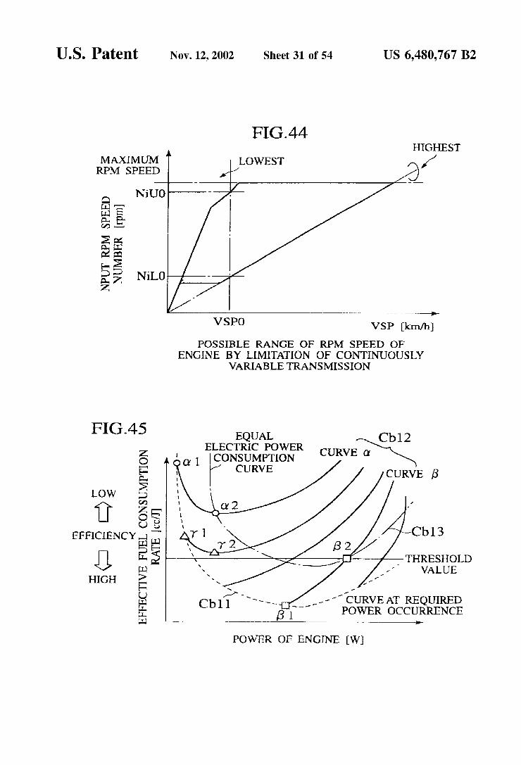
FIG.44 HIGHEST
LOWEST O /1 MAXIMUM RPM SPEED
NiUO
N L O
real-e-
VSPO VSP km/h)
POSSIBLE RANGE OF RPM SPEED OF ENGINE BY LIMITATION OF CONTINUOUSLY
1-CURVE AT REQUIRED 6 POWER OCCURRENCE
VARIABLE TRANSMISSION
'' 53: Cb12 3 CONSUMPTION curve a
Low 2 w 1. 35
EFFICIENCY e Cb 3
25 - THRESHOLD VALUE
HIGH z -
POWER OF ENGINE (W)
US 6,480,767 B2 Sheet 32 of 54
S0 I
97'OIH
Nov. 12, 2002 U.S. Patent
0
|
US 6,480,767 B2 Sheet 33 of 54 Nov. 12, 2002 U.S. Patent
{{NITI TOYALNOJ) — HNIT \{H\\Od 0[HLOATH ----- HÍVd NOISSIWSNWHL _ EIO?HOH TWOHNWHO™IW
0 IZ 607
HOLOWN ZOZ
COCO {{NÍON!!

U.S. Patent Nov. 12, 2002 Sheet 34 of 54 US 6,480,767 B2
FIG.48
RUNNING STATE 211 21 O DETECTOR ,
REQUIRED POWER - 22 CALCULATOR
213 214
PHYSICAL QUANTITY THRESHOLD VALUE PER UNIT POWER CALCULATOR CALCULATOR
OPERATING MODE SELECTOR 216
TARGET UNITTT OPERATING POINT CALCULATOR
217
SOC DETECTOR
218 CHARGING EFFICIENCY CALCULATOR
OPERATING POINT-219 CALCULATOR
22
MOTOR CONTROLLER
ENGINE CONTROLLER
GENERATOR CONTROLLER

U.S. Patent Nov. 12, 2002 Sheet 35 of 54 US 6,480,767 B2
FIG.49 Z C
CURVE AT REQUIRED POWER S. OCCURRENCE P
2 9 s REGION I
S. REGION III A. A
v
D R Cc O -S 2. - THRESHOLD
| VALUE TA :
A. B COMMAND POWER (W)
OPERATING MODE
FIG5 O EFFECTIVE FUEL CONSUMPTION RATE
Z CURVE AT REQUIRED POWER OCCURRENCE C
s SURPLESRYER OF SMALLER GINE CC3
2= GREATEBes1 S5 SMALLER REQUIRED POWER - k
GREATER
g 4 Cc 5 Y. - /- THRESHOLD VALUE i I ( CC2
A
COMMAND POWER WI TARGET UNIT OPERATING POINT CALCULATION (REGION I )
U.S. Patent Nov. 12, 2002 Sheet 36 of 54 US 6,480,767 B2
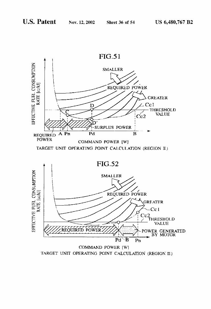
FIG.51
2 P SMALLER
2 p 3 . s u-REQUIRED POWER -
g D Cc w THRESHOLD 3 VALUE
: REQUIRED A Pn Pd B POWER
COMMAND POWER (W) TARGET UNIT OPERATING POINT CALCULATION (REGION II)
FIG.52
SMALLER
3. REQUIRED POWER
w Cc C
-1 CC2 C THRESHOLD
w VALUE
(Ž fÉ66íff powf 2. :3 POWER GENERATED a BY MOTOR
Pd-B Pn COMMAND POWER (W)
TARGET UNIT OPERATING POINT CALCULATION (REGION II)
U.S. Patent Nov. 12, 2002 Sheet 37 of 54 US 6,480,767 B2
FIG.S3
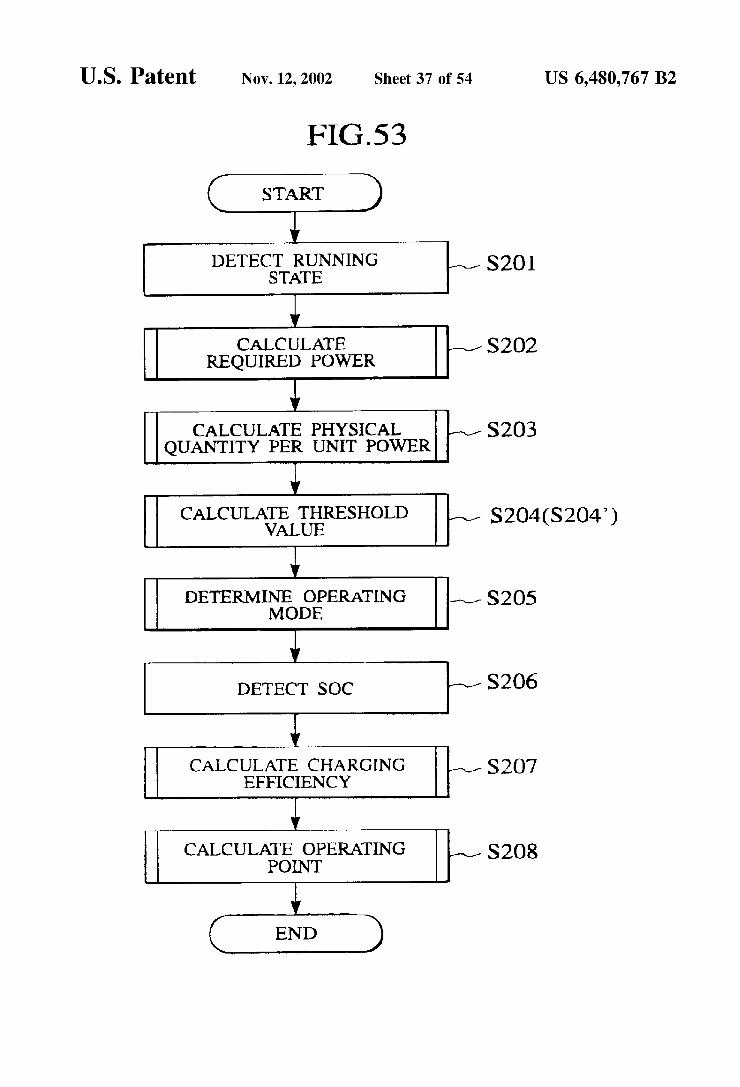
START
DETECT RUNNING
CALCULATE S2O2 REQUIRED POWER
CALCULATE PHYSICAL S2O3 QUANTITY PER UNIT POWER
CALCULATE THRESHOLD p VALUE S204(S204)
DETERMINE OPERATING S2O5 MODE
DETECT SOC S2O6
CALCULATE CHARGING S2O7 EFFICIENCY
CALCULATE OPERATING POINT S208
END
U.S. Patent Nov. 12, 2002 Sheet 38 of 54 US 6,480,767 B2
FIGS4
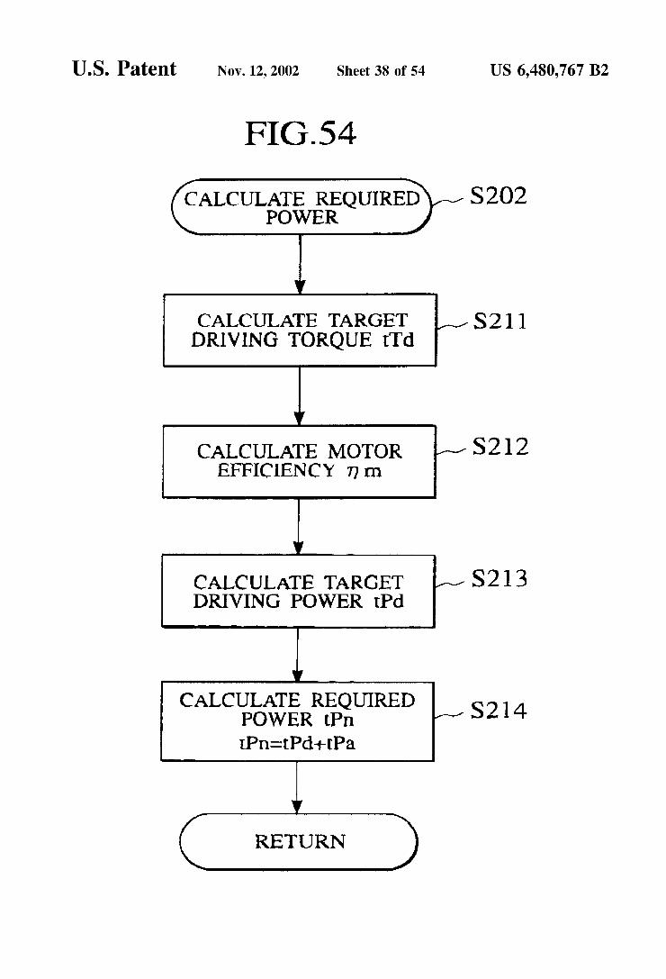
CALCULATE REQUIRED S2O2 POWER
CALCULATE TARGET S21 DRIVING TORQUE iTd
CALCULATE MOTOR S22 EFFICIENCY Trn
CALCULATE TARGET S213 DRIVING POWER Pd
CALCULATE REQUIRED S214 POWER PI PI-cPd--Pa.
RETURN

U.S. Patent Nov. 12, 2002 Sheet 39 of 54 US 6,480,767 B2
FIG.55
Gus Gy?i SEE)” QUANTITY PER UNIT POWER
CALCULATE BEST OPERATING POINT oTe oNe OF
ENGINE S221
CALCULATE FUEL CONSUMPTION RATIO otpn AT BEST OPERATING POINT
S222
CALCULATE PHYSICAL QUANTITY Vn PER UNIT POWER
Vn=oFrpn/Pn
RETURN
FIG.56 CALCULATE
THRESHOLD VALUE
S223
S23
CALCULATE THRESHOLD VALUE Vc
Vcs-KX (ISOC - SOC) -- Vcold S232

U.S. Patent Nov. 12, 2002 Sheet 40 of 54 US 6,480,767 B2
FIG.57
CALCULATION OF S2O4 THRESHOLD VALUE
Vcbasedld - Vcbase S24 SOCold = SOC
CALCULATE THRESHOLD VALUE Vcbase
Vcbase - KX (tSOC SOC) Vcbaseold S242
S243
SOC > SOCold 2 NO
YES S244 S245
RETURN

U.S. Patent Nov. 12, 2002 Sheet 41 of 54 US 6,480,767 B2
Y ES
OPERATING MODE FLAG
Fw = 1
S257
OPERATING MODE FLAG
Fw = 2
OPERATING MODE FLAG
Fw - 4
OPERATING MODE FLAG
Fw = 3
RETURN
FIG.59 CACULATION OF
CHARGING EFFICIENCY
CALCULATE CHARGING EFFICIENCY Tc
RETURN
S261

U.S. Patent Nov. 12, 2002 Sheet 43 of 54 US 6,480,767 B2
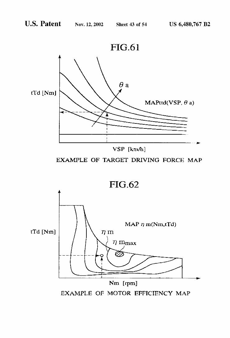
FIG.61
6 a tTd NIn
N MAPtd(VSP, 6a)
VSP km/h)
EXAMPLE OF TARGET DRIVING FORCE MAP
FIG.62
MAP 7 In(NIn, Tod) Td NIn
Nm rpm EXAMPLE OF MOTOR EFFICIENCY MAP

U.S. Patent Nov. 12, 2002 Sheet 44 of 54 US 6,480,767 B2
FIG.63
oTe Nin
e
oNe (rpm) EXAMPLE OF OPERATING POINT OF ENGINE
FIG.64
oTe NIn
oNe (rpm) FUEL CONSUMPTION RATE CHARACTERISTIC ce/sec)

U.S. Patent Nov. 12, 2002 Sheet 45 of 54 US 6,480,767 B2
FIG.65 MINIMUM FUEL CONSUMPTION RATE Penin (Nernin, Tennin)
REVOLUTION NUMBER rpm MINIMUM FUEL CONSUMPTION RATE CHARACTERISTIC g/kwh.
FIG.66
SOC (%) EXAMPLE OF CHARGING EFFICIENCY
CHARACTERISTIC %

U.S. Patent Nov. 12, 2002 Sheet 46 of 54 US 6,480,767 B2
FIG.67 PRESENT INVENTION
CCl2 PRIOR ART
PO - - - - - - - - - - - - - -4------ INT 3 1-CC
- - - - - - -- m - - - - - - - - ------THRESHOLD
POINT VALUE
SURPLUS POWER IS INCREASED
LOW
EFFICIENCY s
HIGH
O 28 3O
POWER OF ENGINE kW
FIG.68 GREATER
(a. 2. SURPLUS POWER CC22 O IS INCREASED
LOW Z.
-
EFFICIENCY 25
C HIGH
EFFECTIVE FUEL CONSUMPTION RATE AT REOURED POWER OCCURRENCE
POWER OF ENGINE (kW)


U.S. Patent Nov. 12, 2002 Sheet 48 of 54 US 6,480,767 B2
DETECTOR
36 CONTINUOUSLY 37
VARIABLE TRANSMISSION TRANSMITTING EFFICIENCY
CALCULATOR
THRESHOLD VALUE CALCULATOR
OPERATING MODE 32O SELECTOR
-- TARGET UNIT OPERATING POINT CALCULATOR
322 SOC
DETECTOR
323 | CHARGING
EFFICIENCY CALCULATOR
I
325 328
CONTINUOUSLY ENGINE VARIABLE CLUTCH
CONTROLLER CONTROLLERTRANSMISSION CONTROLLER CONTROLLER
OUTPUT SHAFT POWER CALCULATOR
3 8 PHYSICAL QUANTITY PER UNIT POWER CALCULATOR
U.S. Patent Nov. 12, 2002 Sheet 49 of 54 US 6,480,767 B2
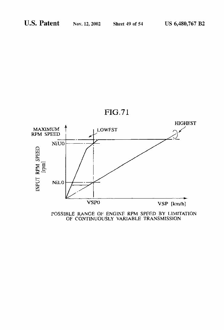
FIG.71 HIGHEST
LOWEST 1 3.
MAXIMUM RPM SPEED
NUO
NiLO
E.
VSPO VSP km/h)
POSSIBLE RANGE OF ENGINE RPM SPEED BY LIMITATION OF CONTINUOUSLY VARIABLE TRANSMISSION

U.S. Patent Nov. 12, 2002 Sheet 50 0f 54 US 6,480,767 B2
FIG.72
START
DETECT RUNNING S30 STATE
CALCULATE OUTPUT S3O2 SHAFT POWER
CALCULATE CONTINUOUSLY S3O3 VARIABLE TRANSMISSION TRANSMITTING EFFICIENCY
CALCULATE PHYSICAL S3O4. QUANTITY PER UNIT POWER
CALCULATE THRESHOLD O5 VALUE S305(S305)
DETERMINE OPERATING MODE S306
DETECT SOC S307
CALCULATE CHARGING S3O8 EFFICIENCY
CALCULATE OPERATING POINT S309
END

U.S. Patent Nov. 12, 2002 Sheet 51 0f 54 US 6,480,767 B2
FIG.73
CALCULATION OF OUTPUT SHAFT POWER
CALCULATE TARGET DRIVING TORQUE Tod
CALCULATE TARGET DRIVING POWER PC
RETURN
S3O2
S311
S32
U.S. Patent Nov. 12, 2002 Sheet 52 0f 54 US 6,480,767 B2
FIG.74
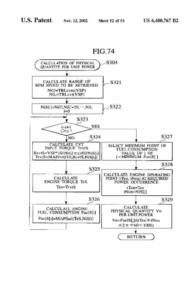
CALCULATION OF PHYSICAL S304 QUANTITY PER UNIT POWER
CALCULATF RANGE OF S32 RPM SPEED TO BE RETRIEVED
NiL-TBLc v(VSP)
NiSi-Nil J.NiO--50, NiL S322 icO
S323 -1
YES
NO S324
CALCULATE CVT INPUT TORQUE Tcvts
RcvtS=VSP* 10/3.6/(27L r)/60/NiSi TcvtS=MAPcvt.(Td,RcvtS,NiSi))
SELECT MINIMUM POINT OF FUEL CONSUMPTION VALUE OF i OF
j= MDNIMUM FuelS
S32S 11 CALCULATE ENGINE OPERATING
POINT (rTen, tNen) AT REQUIRED POWER OCCURRENCE
tTen-Tes Nen=NiSj
CALCULATE ENGINE TORQUE Tes
Tes-TcvS
4-1.
CALCULATE ENGINE FUEL CONSUMPTION Fuel Si FuelSil=MAPfuel (TeS,NiSi)
CALCULATE PHYSICAL QUANTITY Vn
PER UNIT POWER
Vn=FuelS)/(Ten X Nen X27L-60-1000)
RETURN

US 6,480,767 B2 Sheet 54 of 54 Nov. 12, 2002 U.S. Patent
STWNOIS TO\INOO HO NAOTH · · · · · · · · · · · - NO[IOHNNOO TVORILO?IT? — 80WXNITI TVOINWHOHIN —
STV/NOIS I (\d{NI
9
| «… |
S 9.L'OIH
}{{TIOHINOO |× Ovº ?
L
| ? ||
[07
US 6,480,767 B2 1
CONTROL SYSTEM FOR HYBRD VEHICLE
BACKGROUND OF THE INVENTION
The present invention relates to a control System for a hybrid vehicle.
There is disclosed a control system for a hybrid vehicle in Japanese Patent Application Laid-open Publication No. 9-98516. This control system is adapted for application to a parallel hybrid vehicle (P-HEV), and an object of the control System is to reduce the consumption rate or amount of exhaust gas. A feature of this control System is that a physical quantity (fuel consumption rate, exhaust gas ratio, or the like) related to an engine when the vehicle runs using the engine as a power Source, electric power generating efficiency when a generator is driven by the engine when the vehicle runs using a motor as the power Source is converted into electric power, and a physical quantity (fuel consump tion rate, exhaust gas ratio and the like) related to the engine while taking the charging efficiency when the electric power is Stored in a battery is taken into consideration are com pared with each other, and one of them having higher physical quantity (lower one if the fuel consumption rate or exhaust gas ratio is determined as the physical quantity) is Selected as the power Source.
SUMMARY OF THE INVENTION
In the above related art, in a region (low load driving) where consumption output required for running is relatively Small, the engine generates output greater than the consump tion output, the charging is carried out by Surplus output exceeding the consumption output, and in a region (high load driving) where the consumption output required for running is relatively great, the engine generates only the consumption output. When an instantaneous electric charging efficiency is
considered, if the above electric charging is carried out, the charging efficiency is enhanced. However, if the entire driving region is taken into consideration, the charging efficiency when the engine generates an output greater than the consumed output in the high load driving region and the charging is carried out by the Surplus output exceeding the consumed electrical power is better than the charging effi ciency when the engine generates output greater than the consumed output in the low load driving region and the charging is carried out by the Surplus output exceeding the consumed output in Some cases. The charging efficiency, i.e., fuel consumption rate is not always optimized.
Accordingly, in View of the above-described problems, it is an object of the present invention to provide a control system for a hybrid vehicle in which the efficiency over the entire driving region is taken into consideration, and in which the vehicle can run while Selecting a condition having more Suitable predetermined physical quantity Such as the fuel consumption rate or amount of exhaust gas. To achieve the object, in accordance with an aspect of the
present invention, there is provided a control System for a hybrid vehicle for controlling the hybrid vehicle comprising a power apparatus consuming fuel and generating power, a battery Storing electrical power, and a motor converting electrical power to mechanical power transmitted to a drive wheel of the vehicle, the control System including a detector detecting an operating condition of the vehicle, and pro grammed to: calculate a required power indicating a power required to drive the vehicle, based on the operating condi tion of the vehicle, calculate a first parameter indicating a
5
15
25
35
40
45
50
55
60
65
2 ratio between a fuel consumption rate and the required power for running the power apparatus So as to generate a power equal to the required power; Set a threshold value with respect to the first parameter, based on a charging State of the battery; run the power apparatus So as to generate a power larger than the required power when the first parameter is Smaller than the threshold value, and transmit part of the power generated to the drive wheel, and Store a remainder of the power generated in the battery; and run the power apparatus So as to generate a power Smaller than the required power when the first parameter is larger than the threshold value, and transmit all of the power generated to the drive wheel, and transmit part of a power Stored in the battery to the drive wheel.
BRIEF DESCRIPTION OF THE DRAWINGS
The above and further objects and novel features of the present invention will more fully appear from the following detailed description when the same is read in conjunction with the accompanying drawings, in which:
FIG. 1 is a block diagram showing a System Structure of a control System for a hybrid vehicle according to a first embodiment of the present invention;
FIG. 2 is a block diagram showing a functional Structure of an electric power distribution controller in the embodi ment.
FIG. 3 is a graph showing criteria for Selecting operating mode in the embodiment;
FIG. 4 is a graph illustrating a target generated power calculation processing in a region I of the embodiment;
FIG. 5 is a graph illustrating a target generated power calculation processing in a region II of the embodiment;
FIG. 6 is a graph illustrating a target generated power calculation processing in a region III of the embodiment;
FIG. 7 is a main flowchart of processing operation of the embodiment;
FIG. 8 is a flowchart of a battery state detection process ing of the embodiment;
FIG. 9 is a flowchart of a consumption power calculation processing of the embodiment;
FIG. 10 is a flowchart of a physical quantity calculating processing per effective electric power of the embodiment;
FIG. 11 is a flowchart of a threshold value calculating processing of the embodiment;
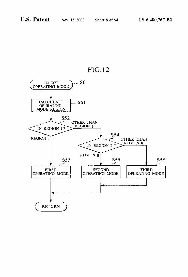
FIG. 12 is a flowchart of an operating mode Selecting processing of the embodiment;
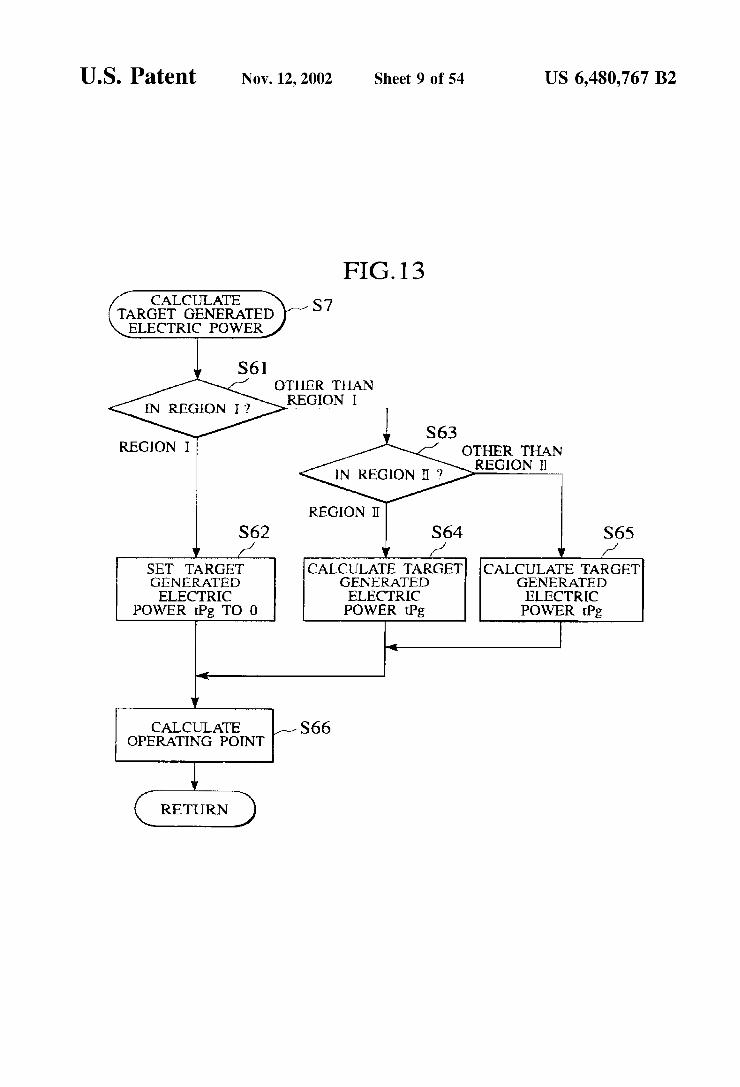
FIG. 13 is a flowchart of a target generated electric power calculating processing of the embodiment;
FIG. 14 is a map of fuel consumption rate characteristic used in the embodiment;
FIG. 15 is a map of target driving force used in the embodiment;
FIG. 16 is a map of motor efficiency used in the embodi ment,
FIG. 17 is a map of effective fuel consumption rate used in the embodiment;
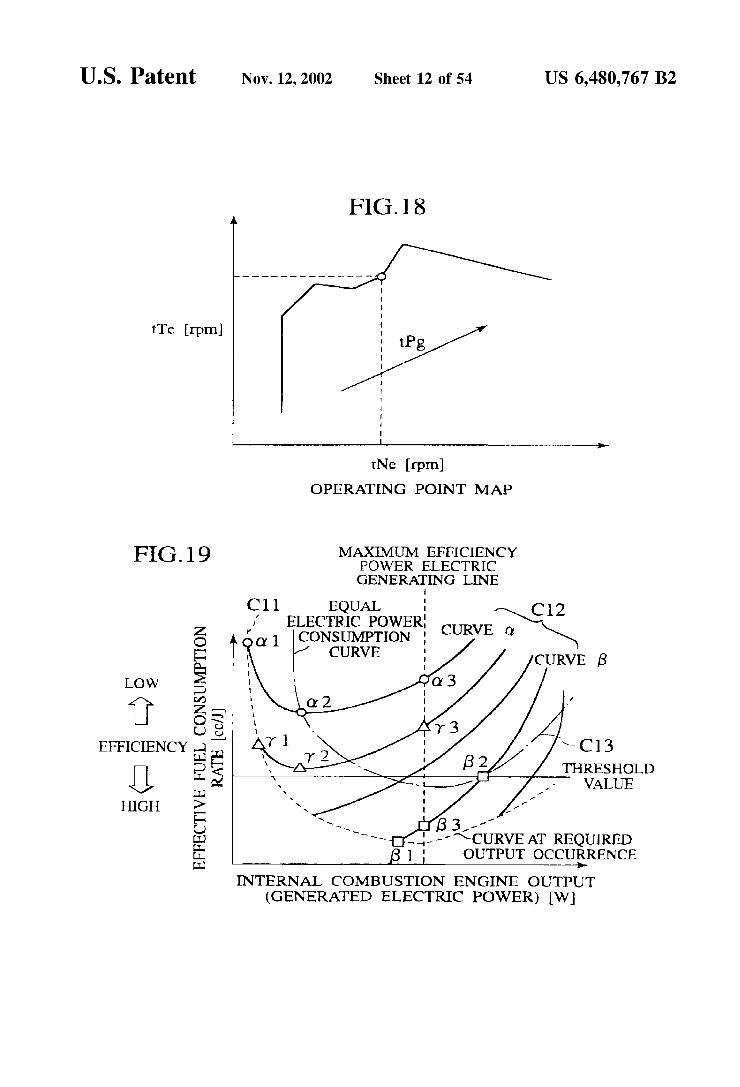
FIG. 18 is a map of operating point used in the embodi ment,
FIG. 19 is a graph showing operation characteristic of the embodiment;
FIG. 20 is a graph showing a relationship between SOC and threshold value used in a Second embodiment;
FIG. 21 is a graph showing a relationship between Voltage between terminals and threshold value used in a third embodiment;

US 6,480,767 B2 3
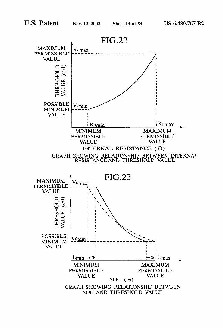
FIG.22 is a graph showing a relationship between internal resistance and threshold value used in a third embodiment;
FIG. 23 is a graph showing a relationship between SOC and threshold value used in a fourth embodiment;
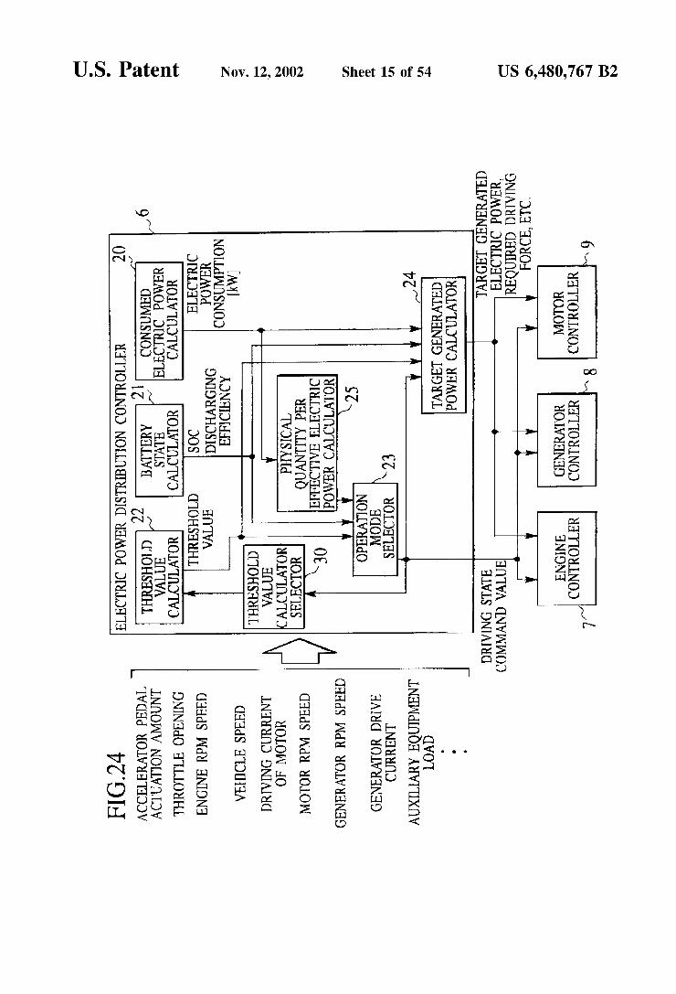
FIG. 24 is a block diagram showing a functional Structure of an electric power distribution controller in a fifth embodi ment,
FIG. 25 is a graph showing a relationship between SOC and threshold value used in the embodiment;
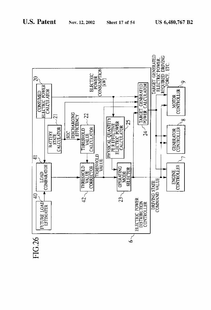
FIG. 26 is a block diagram showing a functional Structure of an electric power distribution controller in a sixth embodiment;
FIG. 27 is a block diagram showing a functional structure of an electric power distribution controller in a Seventh embodiment;
FIG. 28 is a block diagram showing a functional structure of an electric power distribution controller in an eighth embodiment;
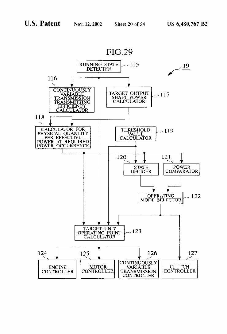
FIG. 29 is a block diagram showing a functional structure of a controller in the embodiment;
FIG. 30 is a graph showing criteria for Selecting operating mode in the embodiment;
FIG. 31 is a diagram illustrating target unit operation point calculating processing (region I);
FIG. 32 is a diagram illustrating target unit operation point calculating processing (region II);
FIG. 33 is a diagram illustrating target unit operation point calculating processing (region III);
FIG. 34 is a flowchart of a main flow of the embodiment; FIG.35 is a detailed flowchart of target output shaft power
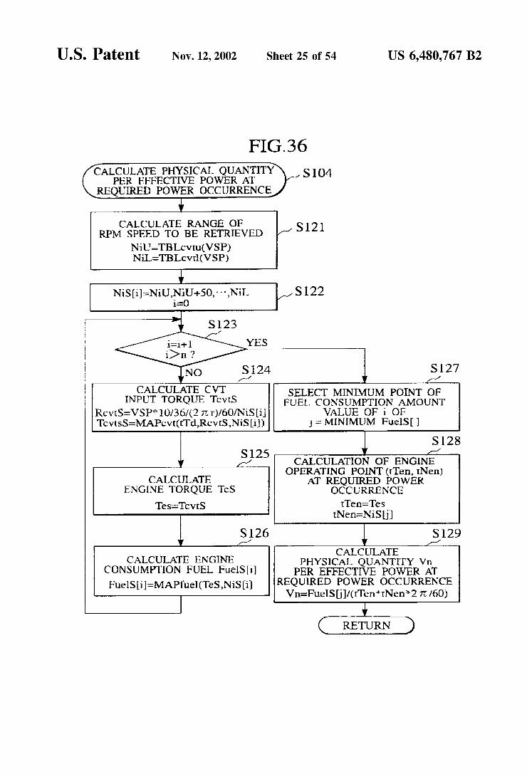
calculating processing in the main flow of the embodiment; FIG. 36 is a detailed flowchart of physical quantity
calculating processing per effective power when required power is occurred in the main flow of the embodiment;
FIG. 37 is a detailed flowchart of threshold value calcu lating processing in the main flow of the embodiment;
FIG.38 is a detailed flowchart of state decision processing in the main flow of the embodiment;
FIG. 39 is a detailed flowchart of power comparison processing in the main flow of the embodiment;
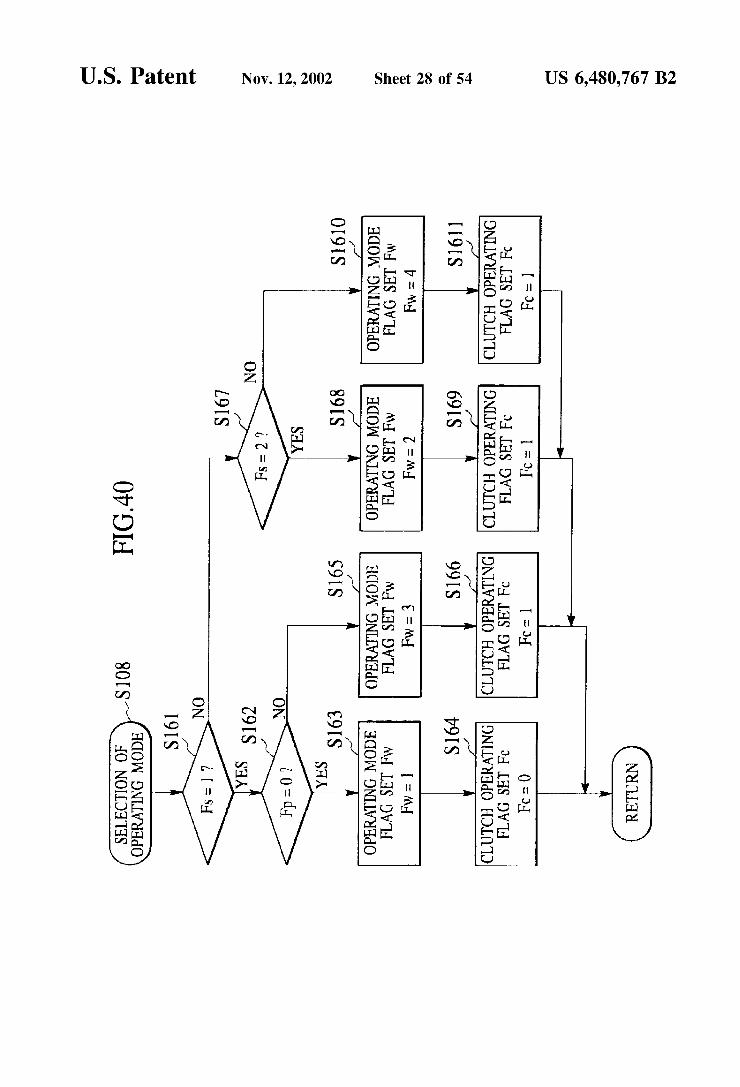
FIG. 40 is a detailed flowchart of operating mode select ing processing in the main flow of the embodiment;
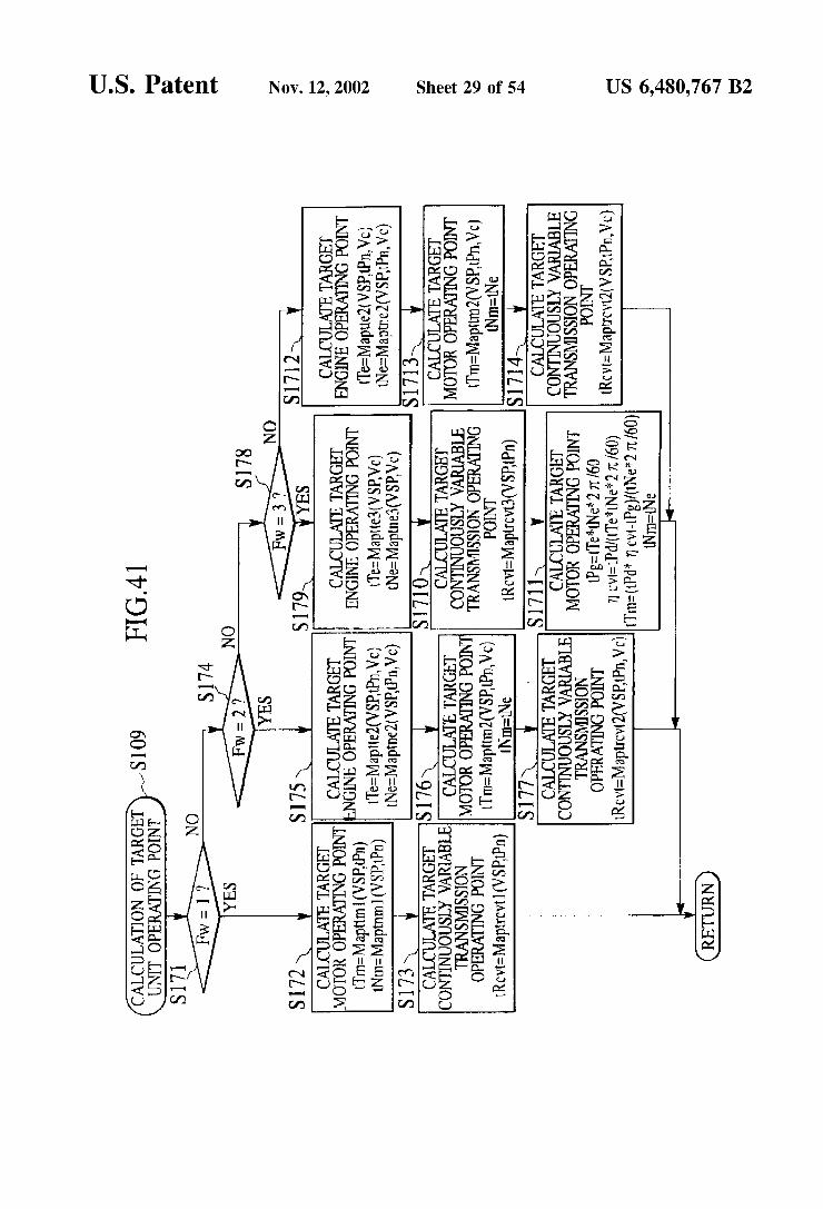
FIG. 41 is a detailed flowchart of target unit operating point calculating processing in the main flow of the embodi ment,
FIG. 42 is a graph showing fuel consumption rate char acteristic in a hybrid vehicle of the embodiment;
FIG. 43 is a graph showing one example of a target driving force map in the hybrid vehicle of the embodiment;
FIG. 44 is a graph showing possible range of rpm Speed of an engine of the hybrid vehicle of the embodiment;
FIG. 45 is a graph showing operation characteristic of the embodiment;
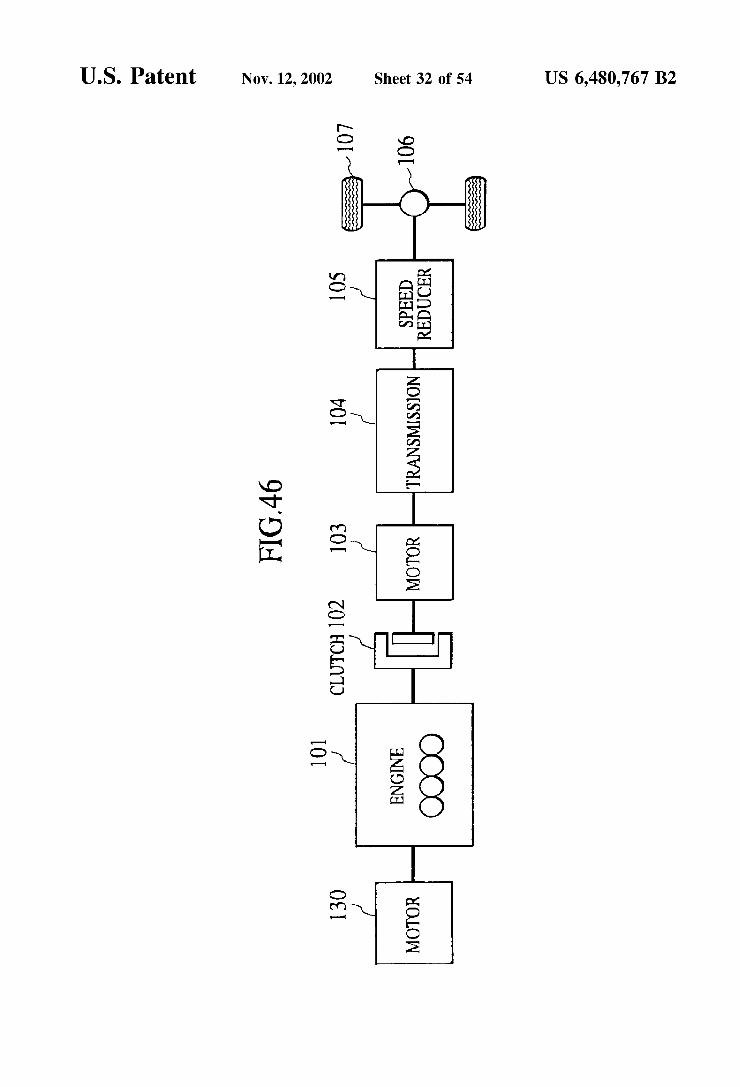
FIG. 46 is a block diagram showing a power train of a ninth embodiment of the invention;
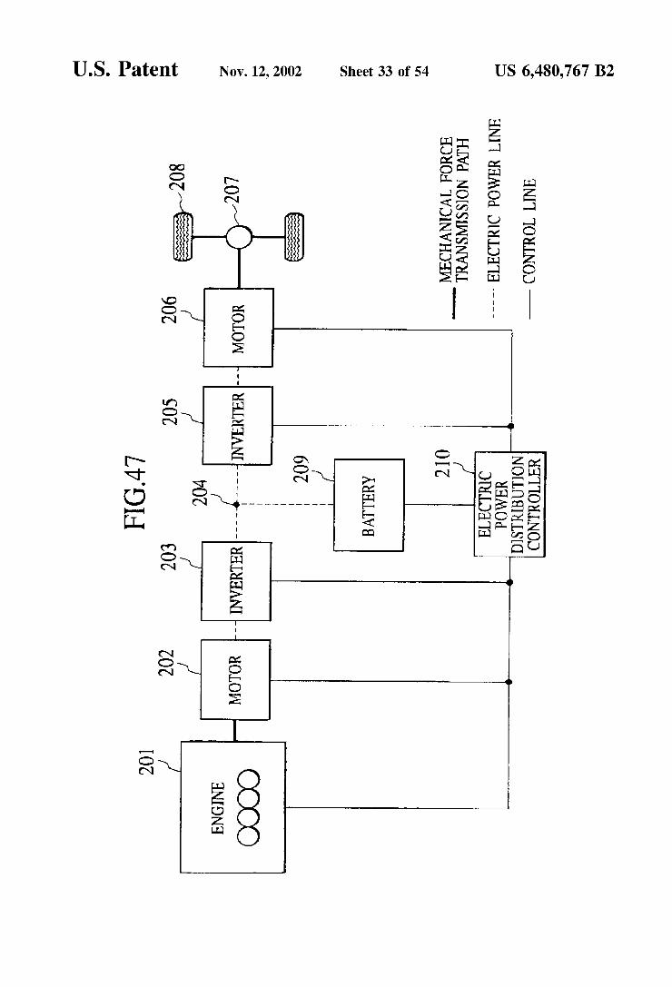
FIG. 47 is a block diagram showing a system structure of a control system for a hybrid vehicle of a tenth embodiment;
FIG. 48 is a block diagram showing a functional structure of an electric power distribution controller of the embodi ment,
FIG. 49 is a graph showing criteria for Selecting operating mode in the embodiment;
15
25
35
40
45
50
55
60
65
4 FIG. 50 is an explanatory view of target unit operating
point calculating processing in the embodiment (region I); FIG. 51 is an explanatory view of target unit operating
point calculating processing in the embodiment (region II); FIG. 52 is an explanatory view of target unit operating
point calculating processing in the embodiment (region III); FIG. 53 is a flowchart of a main flow of the embodiment; FIG. 54 is a detailed flowchart of required power calcu
lating processing in the main flow of the embodiment; FIG. 55 is a detailed flowchart of physical quantity
calculating processing per unit time in the main flow of the embodiment;
FIG. 56 is a detailed flowchart of threshold value calcu lating processing in the main flow of the embodiment;
FIG. 57 is a detailed flowchart of state decision processing in the main flow of the embodiment;
FIG. 58 is a detailed flowchart of operating mode deter mining processing in the main flow of the embodiment;
FIG. 59 is a detailed flowchart of charging efficiency calculating processing in the main flow of the embodiment;
FIG. 60 is a detailed flowchart of operating point calcu lating processing in the main flow of the embodiment;
FIG. 61 is a graph of an example of target driving force map in the hybrid vehicle of the embodiment;
FIG. 62 is a graph of an example of motor efficiency in the hybrid vehicle of the embodiment;
FIG. 63 is a graph of an example of operating point of an engine in the hybrid vehicle of the embodiment;
FIG. 64 is a graph of fuel consumption rate characteristic in the hybrid vehicle of the embodiment;
FIG. 65 is a graph showing minimum fuel consumption rate characteristic in the hybrid vehicle of the embodiment;
FIG. 66 is a graph showing charging efficiency charac teristic in the hybrid vehicle of the embodiment;
FIG. 67 is a graph showing working effect of the embodi ment,
FIG. 68 is a graph showing operation characteristic of the hybrid vehicle of the embodiment;
FIG. 69 is a block diagram showing a power train of an eleventh embodiment; FIG.70 is a block diagram showing a functional structure
of an electric power distribution controller of the embodi ment,
FIG. 71 is a graph showing possible range of rpm Speed of an engine by limitation of a continuously variable trans mission of the embodiment; FIG.72 is a flowchart of a main flow of the embodiment; FIG. 73 is a detailed flowchart of output shaft power
calculating processing in the main flow of the embodiment; FIG. 74 is a detailed flowchart of physical quantity
calculating processing per unit power in the main flow of the embodiment;
FIG. 75 is a detailed flow of operating point calculating processing in the main flow of the embodiment; and
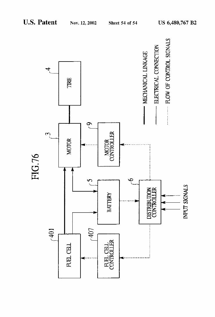
FIG. 76 is a block diagram showing a system structure of a control System for a hybrid vehicle according to a thir teenth embodiment of the present invention.
DESCRIPTION OF THE PREFERRED EMBODIMENTS
Embodiments of the present invention are described in detail below, making reference to relevant accompanying

US 6,480,767 B2 S
drawings. Like members or elements are designated by like reference characters.
FIG. 1 shows a first embodiment of the invention. An internal combustion engine 1 (hereinafter Sometimes referred to simply as an engine) drives a generator 2 to generate electricity. A fuel cell (see FIG. 76) is employed as the generator in Some cases, but in this case, the engine 1 and the generator 2 are employed as an electric power generating apparatuS.
Electric power generated by the generator 2 drives a motor 3, a driving force of which is transmitted to a road Surface through tires 4, thereby allowing a vehicle to run. When the electric power generated by the generator 2 is greater than electric power consumed by the motor 3, electric power is Stored in a battery 5 as Surplus electric power. When the electric power generated by the generator 2 is smaller than that consumed by the motor 3, insufficient electric power is discharged from the battery 5 and Supplied to the motor 3.
An electric power distribution controller 6 establishes the method of Setting the driving States of the engine 1, the generator 2 and the motor 3, and generates command values for the engine 1, the generator 2 and the motor 3 So as to achieve that State and Satisfy a driver's requirements. An engine controller 7 (hereinafter Sometimes referred to
Simply as an engine controller) controls the engine 1 to achieve the command value (e.g., required output) from the electric power distribution controller 6. A generator control ler 8 controls the generator 2 to achieve the command value (e.g., required amount of generated electric power) from the electric power distribution controller 6. A motor controller 9 controls the motor 3 to achieve the command value (e.g., the required driving force) from the electric power distribution controller 6.
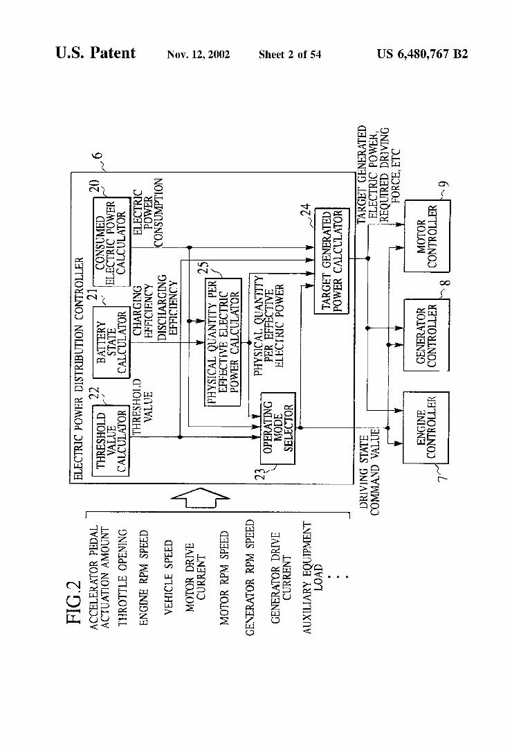
Referring to FIG. 2, the structure and operation of the electric power distribution controller 6 are as follows. Input from various vehicle-mounted Sensors (not shown) to the electric power distribution controller 6 are physical quantity and conversion quantity corresponding to the physical quan tity representing the vehicle States, Such as accelerator pedal actuation amount, throttle opening, rpm Speed of the engine, vehicle Speed, motor drive current, motor rpm Speed, gen erator drive current, generator rpm Speed and auxiliary equipment load. A consumed electric power calculator 20 of the electric
power distribution controller 6 obtains required driving force of the driver from the vehicle speed and the accelera tion pedal actuation amount at that time, and calculates currently required consumption electric power while taking the driving state of the auxiliary equipment (air conditioner, radiator fan, rear defogger and the like), motor efficiency and inverter efficiency into consideration. A battery state calculator 21 of the electric power distri
bution controller 6 obtains electric power coming in or out from the battery 5 from current coming in or out from the battery 5 and Voltage between terminals at that time, esti mates state of charge (SOC) of the battery 5, detects a temperature of the battery from a temperature Sensor (not shown) disposed in the battery 5, and calculates energy conversion efficiency (charging efficiency) when electric energy is charged from the battery 5 and energy conversion efficiency (discharging efficiency) when the electric energy is drawn from the battery 5 based on the SOC and the temperature of the battery. A threshold value calculator 22 of the electric power
distribution controller 6 calculates the physical quantity
15
25
35
40
45
50
55
60
65
6 Serving as a criteria for evaluating the engine. For example, if energy utilizing efficiency is to be enhanced, the threshold value calculator 22 calculates fuel consumption amount or value corresponding thereto per unit energy as the physical quantity, and if the exhaust gas should be reduced to minimum value, the exhaust gas amount per unit energy is Selected. When the electric power generating apparatus is a fuel cell, physical quantity concerning the fuel cell is Selected based on the same idea.
For Simplifying the explanation, the control for minimiz ing the fuel consumption amount will be explained. In this case, the threshold value obtained by the threshold value calculator 22 is indicated with fuel amount (cc/J:, “effec tive fuel consumption rate”, hereinafter) which is consumed for generating the unit output which can be utilized effec tively. There, the output which can be utilized effectively means net energy given to the motor 3, and generated electric power for driving the motor 3 is obtained from the fuel consumption characteristic of the engine 1 and the electric power generating efficiency of the generator 2. Electric power to be stored in the battery 5 is obtained while taking fuel consumption rate characteristic of the engine 1, electric power generating efficiency of the generator 2, charging efficiency to the battery 5 and discharging effi ciency from the battery 5 into consideration. To be strict, the charging efficiency and the discharging efficiency are different, and precise efficiency at the time of discharging is varied depending upon the current value at that time, but the precise efficiency is replaced by average discharging efficiency, or charging and discharging efficiencies are com bined as one, and the average fixed value is used as the precise discharging efficiency. A physical quantity per effective electric power calculator
25 calculates physical quantity per effective electric power when electric power is generated in the electric power generating apparatus based on electric power consumption obtained by the consumed electrical power calculator 20, the charging efficiency and discharging efficiency calculated by the battery state calculator 21 (in this embodiment, effective fuel consumption rate is calculated). For calculating the physical quantity per effective electric power, map data may be previously obtained and utilized. An operating mode Selector 23 in the electric power
distribution controller 6 decides whether the engine 1, the generator 2 and the motor 3 should be driven or Stopped based on the threshold value obtained by the threshold value calculator 22 and the effective fuel consumption rate calcu lated by the physical quantity per effective electric power calculator 25, and based on a result of the decision, the operating mode Selector 23 outputs driving State command to the engine controller 7, the generator controller 8 and the motor controller 9.
A target generated electric power calculator 24 in the electric power distribution controller 6 calculates a target operating point of each of the engine 1, the generator 2 and the motor 3 based on the threshold value obtained by the threshold value calculator 22, electric power consumption obtained by the consumed electrical power calculator 20, decision results of driving/stopping of the engine 1, the generator 2 and the motor 3 obtained by the operating mode Selector 23. The target generated electric power calculator 24 outputs a result of the calculation to the engine controller 7, the generator controller 8 and the motor controller 9.
Next, detailed function of the operating mode selector 23 will be explained with reference to FIG. 3. FIG. 3 shows a curve C1 showing effective fuel consumption rate and chain
US 6,480,767 B2 7
line C2 showing the threshold value when electricity which is equal to consumed electrical power is generated using the electric power generating apparatus. A and B are points of intersection of these curves C1 and C2. The threshold value C2 is calculated by the threshold value calculator 22. In this control System, the operating mode of the electric power generating apparatus (engine 1 and the generator 2) and the battery 5, and a target generated electric power in the electric power generating apparatus are Set So that electric power is generated Such that effective fuel consumption rate becomes equal to or lower than the threshold value C2.
<region I>: When the electric power consumption is lower than AkW (region I), since the curve C1 showing the effective fuel consumption rate is greater than the threshold value C2, electric power is not generated, and electric power stored in the battery 5 is discharged to drive the motor 3, thereby allowing the vehicle to run. In this case, a mode is controlled Such that the engine 1 is Stopped, the generator 2 is stopped and the battery 5 discharges.
<region II>: When the electric power consumption is equal to or greater than AkW) and equal to or lower than BkW), since the curve C1 showing the effective fuel consumption rate is equal to or lower than the threshold value C2, the battery 5 is charged with electricity. In this region, Since the effective fuel consumption rate is Suffi ciently higher than the threshold value, the output of the engine 1 is increased, the electric power is generated by Surplus output greater than the electric power required for driving the vehicle, and the battery 5 is charged with the Surplus electric power.
The reason why the output of the engine 1 is excessively increased and the battery 5 is charged with electric power is that the vehicle runs using electric power which is efficiently charged with the threshold value or lower in a region where the effective fuel consumption rate is greater than the threshold value, and the fuel consumption is enhanced entirely as a result. Therefore, in this case, the mode is controlled Such that the engine 1 is driven, the generator 2 is driven and the battery 5 is charged with electric power.
<region III>: When the electric power consumption exceeds the BkW), since the curve C1 showing the effective fuel consumption rate is greater than the threshold value C2, BkW capable of generating the maximum electric power at threshold value C2 or lower is generated by the engine 1, insufficient electric power with respect to the electric power consumption is discharged from the battery 5, and the motor 3 is driven by the total electric power. In this case, the mode is controlled Such that the engine 1 is driven, the generator 2 is driven and the battery 5 discharges. AS in the case in which the electric power consumption is lower than the AkW), it seems that all the electric power can be obtained by the discharging of the battery 5. However, since electric power coming in or out from the battery 5 is increased, the loSS of electric power is also increased and thus, Such a method is not practical. However, when it is expected that a large quantity of electric power can be collected by regen erative braking at later Stage, this method may be used. Such examples will be described later. When the electric power consumption is equal to the
AkW or BkW), since the curve C1 and the threshold value C2 coincide with each other, direct electric power distribu tion is carried out.
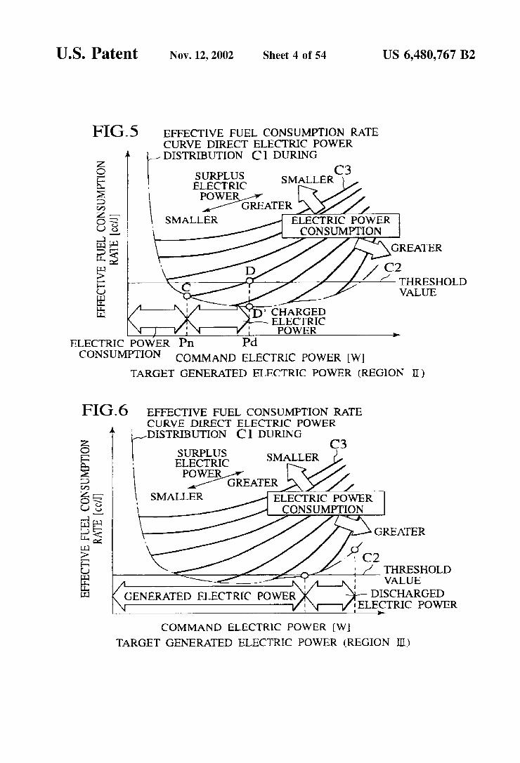
Next, functions of the target generated electric power calculator 24 will be explained with reference to FIGS. 4 to 6. FIGS. 4 to 6 show an effective fuel consumption rate curve C1 and the threshold value C2 at the time of direct
15
25
35
40
45
50
55
60
65
8 electric power distribution, and curves C3 showing the effective fuel consumption rate when electric power con Sumption required for running of the vehicle of auxiliary equipment is equal to a predetermined value and Surplus electric power with respect to the electric power consump tion is generated and the Surplus electric power is increased. Each of the curves C3 is obtained for each electric power consumption, and a Solid line closer to right Side shows greater electric power consumption. As shown in FIG. 4, when the electric power consumption
is in the region I, the electric power consumption calculated by the consumed electrical power calculator 20 is discharged from the battery 5, and the discharged electric power drives the motor 3 and the auxiliary equipment.
FIG. 5 shows a case in which the electric power con Sumption is in the region II. In this case, even if the electric power consumption calculated in the consumed electrical power calculator 20 is Supplied through direct electric power distribution, the effective fuel consumption rate is Smaller than the threshold value. For example, if a certain point in the region II is defined as C, it seems that the electric power can be directly distributed at this point C. However, if the electric power is directly distributed, Since electric power consumption is compensated by electric power Supplied from the battery 5 to enhance the fuel economy in a region where the effective fuel consumption rate is greater than the threshold value, it is preferable that the battery 5 is charged with electric power as efficiently as possible in a region where the effective fuel consumption rate is equal to or smaller than the threshold value. Thereupon, the electric power is generated in a D point in the drawing So that the output of the engine 1 is increased (=Pd) and the effective fuel consumption rate becomes equal to the threshold value. The Surplus electric power (=generated electric power Pd-electric power consumption Pn (electric power con Sumed by running and auxiliary equipment)) which is a difference between the generated electric power at this point D is input to the battery 5.
Here, if attention is paid to the effective fuel consumption rate of electric power (electric power generated by the engine 1 and the generator 2) before the electric power is collected by the battery 5 when the electric power is gen erated at the point D, the point becomes a point D'. A difference of effective fuel consumption rate between the points D and D" is generated from loSS of electric energy with respect to electric power coming in and out from the battery 5. For example, if a rate of loSS of electric energy is assumed to be constant, the loSS in electric energy becomes greater as the Surplus electric power is greater. That is, the difference between the points D and D' is increased. The generated electric power at that time can be calcu
lated by previously obtaining map data as shown in FIG. 5. This map data is formed by obtaining effective fuel con Sumption rate at the time when the electric power consump tion is used as a parameter and charging electric power to be added to the parameter, and by forming the obtained effec tive fuel consumption rate as a map ("effective fuel con Sumption rate map', hereafter). Therefore, the electric power actually consumed by the motor 3 is Surplus electric powerx charging efficiencyxdischarging efficiency. Of course, it is possible to allow a CPU of the control system to calculate based on previously registered predetermined arithmetic equation without forming the data in the form of the map.
FIG. 6 shows a case in which the electric power con Sumption is in the region III. In this case, if electric power consumption calculated by the consumed electrical power

US 6,480,767 B2
calculator 20 is directly distributed, the effective fuel con Sumption rate becomes greater than the threshold value. Therefore, the generated electric power is Set to the maxi mum electric power which is lower than the threshold value, the insufficient electric power (=electric power consumption Pn-generated electric power Pd) is discharged from the battery 5, and a total thereof is used for driving the motor 3 and the auxiliary equipment.
Next, the control of the electric power distribution con troller 6 will be explained concretely using flowcharts in FIGS. 7 to 13. The processing shown in the flowcharts is repeatedly carried out in a cycle of predetermined time.
FIG. 7 shows main processing flow. In Step S1, Signals indicative of vehicle running State Such as an accelerator pedal actuation amount 0adeg, a vehicle speed VSPkm/h), a motor electric power consumption, generated electric power by the generator, auxiliary equipment load electric power PoWare read in. In step S2, the charging state SOC, the charging efficiency mc and discharging efficiency md are calculated. In Step S3, the currently required electric power consumption tPn is calculated from the driving force required by the driver and the driving State of the auxiliary equipment (ON/OFF of air conditioner, instantaneous required driving force).
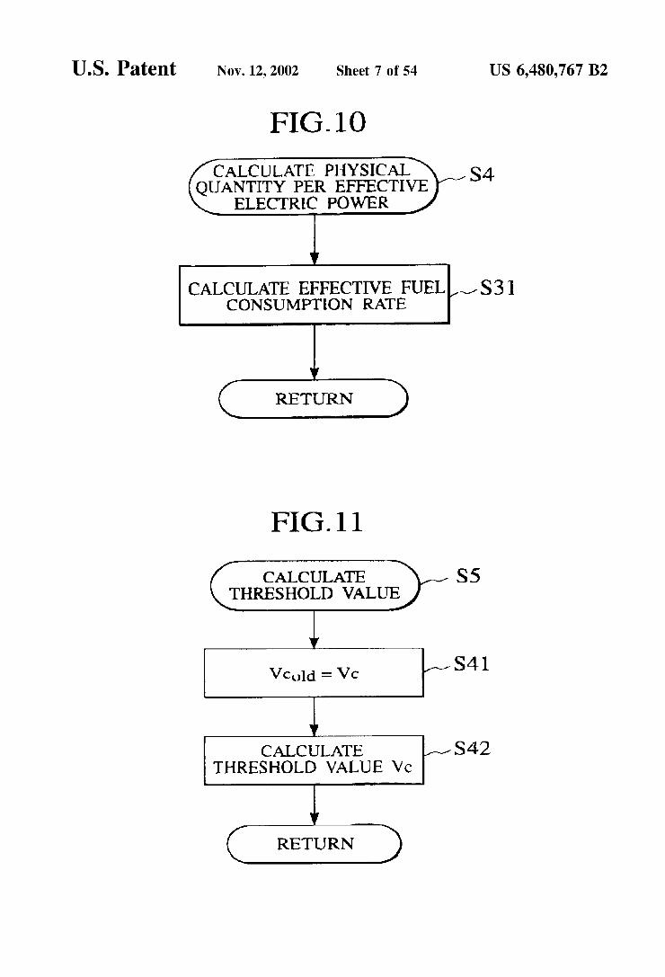
In Step S4, the physical quantity per effective electric power is calculated based on the charging efficiency mc and discharging efficiency md calculated by the battery State calculator 21. In step S5, a threshold value for selecting operation of the engine 1 and the battery 5 is calculated.
In Step S6, the operating mode is Selected based on the threshold value, the electric power consumption and the physical quantity per effective electric power. In Step S7, a target generated electric power is calculated from the thresh old value, the electric power consumption, a result of Selection of the operating mode and the physical quantity per effective electric power, and an operating point of the engine 1 and the generator 2 at the time of generation of electric power is calculated.
Details of the battery State detecting processing in Step S2 of the main flowchart are as shown in the flowchart in FIG. 8. In this processing, the charging State SOC of the battery 5 is calculated from current coming in and out from the battery 5 and Voltage between terminals at that time in Step S11. In Step S12, the charging efficiency mc and the dis charging efficiency md are calculated based on the SOC and the temperature of the battery. An average value of the values at the time of past charging and discharging may be calculated alternatively.
Details of the electric power consumption calculating processing in Step S3 of the main flow are as shown in the flowchart in FIG. 9. In step S21, the target driving torque tTdNm is calculated from parameters Such as the accel erator pedal actuation amount 0a and the vehicle speed VSP Data (map data and the like) required for calculating the target driving torque is previously obtained by experiment or the like, and is stored in a memory (not shown) of the electric power distribution controller 6. FIG. 15 shows an example of the target driving torque calculating map. A Speed-target driving torque curve (e.g., 0a1) is selected by accelerator pedal operating amount, and a corresponding target driving torque (e.g., tTod1) is determined from the vehicle speed (e.g., VSP1) on the curve 0a1.
Subsequently, in Step S22, a motor efficiency mm when electric energy is converted into kinetic energy in the motor 3 is calculated. Data (map data or the like) required for calculated this motor efficiency mm is previously obtained
15
25
35
40
45
50
55
60
65
10 by experiment or the like, and stored in a memory. FIG. 16 shows an example of a motor efficiency calculating map. In FIG. 16, an equal motor efficiency line is shown. A shaded range Nm, has highest motor efficiency, and the motor efficiency is lowered toward the outer side. Referring to this map data, if the motor rpm Speed is Nm1 and the target driving torque obtained in Step S21 is tTod1, the equal motor efficiency line Nm1 passing both the interSections is obtained. In Subsequent Step S23, a electric power consump tion tPnW) is calculated using the following equation 1 based on the target driving torque rTd and the motor rpm speed Nm:
27t 1 Equation 1 tPn = Tcl. -e-. Ninn. - + Po
60 in
Details of calculating processing of the physical quantity per effective electric power in step S4 of the main flow are as shown in the flowchart in FIG. 10. The processing here corresponds to processing for obtaining the curves C1 and C3 in FIGS. 3 to 6. More specifically, Surplus electric power is added to the electric power consumption to obtain the grOSS generated electric power. The groSS generated electric power is multiplied by electric power generation efficiency to obtain a target output of the engine 1. A fuel consumption rate capable of achieving this target output with minimum fuel consumption rate is obtained from a fuel consumption rate characteristic map shown in FIG. 14. Next, the surplus electric power is multiplied by the charging efficiency mc and the discharging efficiency md obtained by the battery State calculating processing in Step S2 to obtain effective electric power concerning the Surplus electric power. The electric power consumption tPn is added to the effective electric power to obtain groSS effective electric power. Finally, the fuel consumption rate is divided by the groSS effective electric power to obtain the effective fuel consump tion rate. Such calculation is carried out with respect to various electric power consumption and Surplus electric power to calculate the effective fuel consumption rate cor responding to the curves C1 and C3. A unit of the fuel consumption rate is cc/s), and a unit of
electric power is W=J/s). Therefore, a unit of the effective fuel consumption rate obtain by dividing the fuel consump tion rate by the effective electric power is cc/J. Here, the reason why the value obtained by multiplying the Surplus electric power by the charging efficiency mc and the dis charging efficiency md is that slight loSS is generated during charging and discharging if the battery 5 is once charged with the Surplus electric power and this Surplus electric power is consumed by the motor 3 or the like in the future and thus, this loSS is taken into consideration. The effective fuel consumption rate curve C1 at the time
of direct distribution of electric power during which the Surplus electric power is 0 can be calculated without using the charging efficiency mc and the discharging efficiency md of the battery 5. It is therefore possible to priorly calculate the effective fuel consumption rate curve C1, and data of the effective fuel consumption rate curve C1 may be formed in a form of a map and Stored in the memory. Whereas, the effective fuel consumption rate curve C3 at
the time of Surplus electric power charging during which the Surplus electric power is not 0 always need to be calculated by carrying out the above calculation. However, effective fuel consumption rate curve C3 required in step S7 is only one corresponding to the electric power consumption tPn obtained in the electric power consumption calculating
US 6,480,767 B2 11
processing in Step S3 and thus, only this may be calculated (the electric power is fixed to tRn and the above calculation is carried out for various Surplus electric power). If degree of variation of the charging efficiency mc and discharging efficiency md is Small and there is no problem for using averaged fixed value, it is possible to previously calculate the effective fuel consumption rate curve C3. In this case, all the effective fuel consumption rate data can be formed in the form of a map and Stored in the memory. In this case, the processing in Step S4 and Step S12 is unnecessary.
Details of the threshold value calculating processing in step S5 of the main flow are as shown in the flowchart in FIG. 11. A threshold value Vccc/J for selecting the oper ating mode of the engine 1 and the battery 5 is defined as Vc (step S41). Subsequently, a proportion control is carried out based on deviation of a target SOC value tSOCI% (e.g., SOC=50%) and SOC value SOCI% of the battery 5 obtained in the battery State calculating processing in step S2, and the threshold value Vccc/J is calculated (step S42). This threshold value Vc is calculated using equation 2.
Vc=K(tSOC-SOC)+Vc Equation 2 Details of the operating mode Selecting processing in Step
S6 of the main flow are as shown in the flowchart in FIG. 12. First, in Step S51, a judgment is made as to which one of the regions I to III in FIG. 3 the electric power consumption tPn obtained in the electric power consumption calculating processing in Step S3 belongs, based on the effective fuel consumption rate curve C1 obtained in the physical quantity calculating processing per effective electric power in Step S4 and the threshold value Vc obtained in the threshold value calculating processing in Step S5. More Specifically, electric power corresponding to the interSection between the effec tive fuel consumption rate curve C1 and the threshold value Vc is obtained, and this and the electric power consumption tPn are compared to decide the region.
If it was judged that the electric power consumption tPn belonged to region I in Step S51, the operating mode is Set to a first operating mode (steps S52 and S53). If it was judged that the electric power consumption tPn belonged to region II in Step S51, the operating mode is Set to a Second operating mode (steps S52, S54 and S55). If it was judged that the electric power consumption tPn belonged to region III in Step S51, the operating mode is Set to a third operating mode (steps S54 and S56).
Details of the target generated electric power calculating processing in Step S7 of the main flow are as shown in the flowchart in FIG. 13. If the judgment result is region I in step S6 and the first operating mode is Selected, the target generated electric power tFgDWI of the generator 2 is set to 0 as explained with reference to FIG. 4 (steps S61 and S62). In this case, all electric power to be consumed by the motor 3 and the like is sent from the battery 5.
If the judgment result is region II in step S6 and the Second operating mode is Selected, the target generated electric power t?g is calculated based on the effective fuel consumption rate curve C3 obtained in the physical quantity calculating processing per effective electric power in Step S4 and based on the threshold value Vc obtained in the thresh old value calculating processing in Step S5 as explained with reference to FIG. 5 (steps S61, S63 and S64). More Specifically, electric power at an interSection between the threshold value Vc and the curve C3 corresponding to the electric power consumption tPn among the effective fuel consumption rate curves C3 is defined as a target generated electric power t?g. In this case, Surplus electric power with respect to the electric power consumption tPn is charged into the battery 5.
15
25
35
40
45
50
55
60
65
12 If the judgment result is region III in step S6 and the third
operating mode is Selected, the target generated electric power t?g is calculated based on the effective fuel consump tion rate curve C1 obtained in the physical quantity calcu lating processing per effective electric power in Step S4 and the threshold value Vc obtained in the threshold value calculating processing in Step S5 explained with reference to FIG. 6 (steps S61, S63 and S65). More specifically, a maximum value of intersections between the effective fuel consumption rate curve C1 and the threshold value Vc is defined as the target generated electric power t?g. In this case, insufficient electric power with respect to the electric power consumption tPn is compensated by discharging from the battery 5.
In Step S65, an operating point of the engine 1 and an operating point of the generator 2 Satisfying the target generated electric power tFg are calculated. FIG. 18 shows an example of an operating point map for calculating the operating point of the engine 1. This map is formed while taking the fuel consumption rate of the engine 1 and the electric power generating efficiency into consideration, and the map calculates the operating point Such that the fuel consumption amount when the target generated electric power t?g is generated becomes minimum. In this map, a target engine rpm speed Nerpm and a target engine torque tTeNm) are calculated based on the following equation 3 from a target generator rpm speed tNgrpm and a target generator torque TgNim by retrieving a value correspond ing to a target generated electric power.
tTg=-tTe Equation 3
According to the first embodiment of the present invention, electric power from the electric power generating apparatus (engine 1 and generator 2) is once charged into the battery 5, a physical quantity and a threshold value concern ing the electric power generating apparatus per effective electric power corresponding to electric power consumption which was calculated while taking energy conversion effi ciency of the electric power generating apparatus and the battery 5 at the time of future discharging are compared, thereby determining the operating mode of the electric power generating apparatus and the battery 5 and the target generated electric power of the electric power generating apparatus. Therefore, it is possible to increase or reduce the predetermined physical quantity concerning the electric power generating apparatus as compared with the related art.
Concerning this point, the present invention is compared with the relevant parallel hybrid electric vehicle using FIG. 19. In FIG. 19, a curve C11 shown with a broken line shows an effective fuel consumption rate which is a fuel consump tion amount per effective power (effective electric power amount in the case of the present invention) when required output (electric power consumption in the case of the present invention) to be consumed for running or auxiliary equip ment is generated in the engine (generator 2 in the case of the invention). Curves C12 shown with solid lines show effective fuel consumption rate when Surplus output with respect to required output is generated, and the Surplus output is increased. Each Solid line is for each electric power consumption, and a Solid line closer to right Side shows higher load having greater required output.
In the related art, a power Source at the time of running is relatively compared with efficiency concerning fuel con Sumption amount when the vehicle runs using the engine or the generator, and one of them having higher efficiency is

US 6,480,767 B2 13
Selected. On the other hand, in the present invention, electric power Supply Source (generator 2 and battery 5) to the running motor 3 is Selected using absolute criteria, i.e., threshold values concerning the fuel consumption amount designed by a designer.
For example, if the required output (corresponding to electric power consumption in the present invention) to be consumed for running or auxiliary equipment is C.1, effec tive fuel consumption rate when Surplus output which is equal to or greater than the required output is varied is that shown with the curve C. In this related art, the engine is Selected as a power Source at the time of running of the vehicle, output which is equal to or greater than required output is generated at a point C2 at which efficiency is low in the entire operating points of running is generated, and electric power generated using the Surplus output is charged into the battery 5. However, if the same electric power is charged, it is apparently efficient to generate electricity at an interSection B2 of a chain line equal charging electric power curve C13 on a curve B when the required output is f1. In the related art, however, when the required output is B1, only the required output B1 at which the efficiency in the engine becomes maximum is generated, and the battery 5 is not charged. As a result, the electric power is generated in a low efficient State, and electric power is not generated in efficient State. This means that at the time of a predetermined required output, for example, when the required output is C1, C1 and C2 are compared with each other, and the greater C2 is Selected, and when the required output is Y1, Y2 is Selected, and the required output is Y1, Y1 is selected. This is a cause of Selecting a power Source having higher efficiency if compared relatively and as a result, electric power genera tion in low efficient State is Selected in View of absolute point. That is, in the related art, it is found that a power Source capable of minimizing the fuel consumption amount is not always Selected throughout the entire running of the vehicle.
Whereas, in the case of the present invention, a power Supply Source (electric power generating apparatus and battery 5) to the running motor 3 is selected using absolute criteria which are threshold values concerning the fuel consumption amount Set by the designer. Therefore, under a normal condition, when charging is not required in a hurry, the threshold value is set such that the efficiency is enhanced as high as possible to generate electric power in which efficiency is enhanced. When the electric power is charged in a low efficient State, this is limited to a case in which a designer's will to charge even if the efficiency is low is reflected to the threshold value, and its amount is set to be minimum.
Further, according to the present invention, when the efficiency is lowered if electric power is generated, although it depends on the Setting of the threshold value, the battery 5 charged with electric power in a high efficient State is defined as an electric power Supply Source, thereby avoiding the electric power generation with low efficiency. With this method, the fuel consumption amount can be reduced.
In the case of the related art, a power Source can not be Selected while Setting the efficiency at the time of electric power generation to a predetermined value. This is because that in this case also, the power Source is Selected by relative comparison when it is decided that electric power generation is necessary, and as a result, electric power is generated only when the required output is relatively Small and efficiency is low, and electric power can not be generated when the required electric power is relatively great and the efficiency is high. The efficiency of the operating point is largely varied
15
25
35
40
45
50
55
60
65
14 in accordance with the required output, and the efficiency is remarkably lowered when the required output is low.
Whereas, in the case of the present invention, the thresh old value is Set according to a designer's will to control the efficiency at the time of power generation, and it is possible to Select the electric power Supply Source which allows the vehicle to run at effective fuel consumption rate having a threshold value equal to or lower than the set threshold value. Therefore, it is possible to set the effective fuel consumption rate with minimum threshold value in a range where there is no problem for running, and to reduce the fuel consumption amount more effectively.
Here, the control method of the present invention is compared with a case in which an operating point of an engine which is widely known as a power generation control method on a Series hybrid electric Vehicle is used as a maximum efficiency power generating point in the engine and the generator, thereby generating electric power. In FIG. 19, a vertical thick broken line is a maximum electric power generation efficiency line, and shows an effective fuel con Sumption rate when electric power is generated at the maximum efficiency electric power generating point at the time of required output. In this case also, Selection is largely varied in operating point efficiency in accordance with the required output as in the related art. Further, Since the generation amount of electric power is Small in a high efficient State and the generation amount is great in a low efficient State, low efficient electric power generation is increased naturally. Especially when the required output is low, the efficiency is extremely reduced. The efficiency at the time of electric power generation is varied from lower electric power consumption like Y3->Y3->33. Therefore, in this electric power generation method, the fuel consumption amount through the entire running operation is not always minimum. That is, in this invention, the fuel consumption amount can be reduced more efficiently as described above.
Further, if the physical quantity per effective electric power is defined as an exhaust gas amount per effective electric power in the engine, the exhaust gas amount can be reduced as compared with the related art. The Same can be Said when the electric power generating apparatus is a fuel cell. Further, a designer who applies the present invention only need to use the calculation method of a threshold value. With this operation, the operating mode or target generated electric power can be determined uniquely in accordance with the running State, and a System can be designed with high visibility.
In addition, according to the present embodiment, Since the electric power generating apparatus comprises the engine 1 and the generator 2, a physical quantity concerning the engine 1 can be increased or reduced in a preferred direction as compared with the related art. Further, if a fuel cell is used as the electric power generating apparatus, a physical quantity concerning the fuel cell can be increased or reduced in a preferred direction as compared with the related art. For example, if the physical quantity per effective electric power is defined as an electric power amount of the fuel cell or a fuel consumption amount per electric power, it is possible to reduce the fuel consumption amount with respect to the electric energy as compared with the related art. Further, if the physical quantity per effective electric power is defined as an exhaust gas amount per electric power in the engine or fuel cell, it is possible to reduce the exhaust gas amount with respect to the electric energy as compared with the related art.
Further, according to the present embodiment, by com paring the physical quantity per effective electric power

US 6,480,767 B2 15
corresponding to the electric power consumption and the threshold value with each other, it is possible to Select an operating mode which increases or reduces a predetermined physical quantity concerning the electric power generating apparatus as compared with the related art.
In the first operating mode, Since the electric power consumption is compensated by the discharge of the battery 5, it is unnecessary to generate electric power which dete riorate the efficiency with respect to the threshold value in the electric power generating apparatus. In the Second oper ating mode, Since electric power is generated with equal or better efficiency with respect to the threshold value in the electric power generating apparatus and Surplus electric power with respect to the electric power consumption is charged into the battery 5, the electric power is not generated in a state in which efficiency with respect to the threshold value is deteriorated in the electric power generating appa ratus unlike the first and third operating modes, and the vehicle can run using electric power charged into the battery 5 efficiently.
In the third operating mode, the maximum electric power which is equal to or lower than the threshold value is efficiently generated in the electric power generating apparatus, and insufficient electric power with respect to the electric power consumption is discharged from the battery 5, it is unnecessary to generate electric power which lowers the efficiency with respect to the threshold value. Further, as compared with a case in which all the electric power consumption is compensated by the discharge from the battery 5 at the time of a relatively high load, a large quantity of electric power is not discharged from the battery 5. Therefore, it is possible Suppress an abrupt temperature rise or performance deterioration of the battery 5, and a volume thereof can be reduced.
In the fourth operating mode, the threshold value and the physical quantity per effective electric power corresponding to the electric power consumption are equal to each other, it is possible generate the electric power with efficiency equal to the threshold value in the electric power generating apparatuS.
Next, a control System for a hybrid vehicle according to a second embodiment of the pee will be explained with reference to FIG. 20. A system structure of the second embodiment of the invention is the same as that of the first embodiment shown in FIG. 1, and a functional structure of the electric power distribution controller 6 is also the same as that of the first embodiment shown in FIG. 2. The second embodiment is characterized in a function of a threshold value calculator 22 in the electric power distribution con troller 6.
In the second embodiment, the threshold value calculator 22 determines a physical quantity which is an evaluation criterion concerning the engine 1 in accordance with SOC calculated by the battery state calculator 21. When this physical quantity is an effective fuel consumption rate, the physical quantity is determined in a manner shown in FIG. 20. In FIG. 20, a maximum permissible value Limax and a minimum permissible value Lmin which are respectively upper and lower limit values in a range capable of utilizing the SOC of the battery 5 are respectively associated with a feasible minimum value Vcmin of a fuel consumption rate and a maximum permissible value Vcmax determined by a designer. By establishing the above relation, it is possible to control
the charging and discharging in Such a manner that the charging is permitted only when the effective fuel consump tion rate is good in a State in which the Storing amount of the
15
25
35
40
45
50
55
60
65
16 battery 5 is high, and minimum charging is permitted even through the effective fuel consumption rate is relatively low in a state in which the storing amount of the battery 5 is low.
Next, a third embodiment of the present invention will be explained based on FIG. 21. The third embodiment is also characterized in a function of the threshold value calculator 22 in the electric power distribution controller 6. In the third embodiment, the threshold value calculator 22 determines a physical quantity which is an evaluation criterion concern ing the engine 1 in accordance with Voltage Vb between terminals detected by the battery state calculator 21. When this physical quantity is effective fuel consumption rate, as shown in FIG. 21, a maximum permissible value Vbmax and a minimum permissible value Vbmin which are respectively upper and lower limit values in a range capable of utilizing the voltage Vb between terminals of the battery 5 are respectively associated with a feasible minimum value Vcmin of a fuel consumption rate and a maximum permis Sible value Vcmax determined by a designer. With this relation, it is possible to control the charging and
discharging in Such a manner that when the Voltage Vb between terminals is high, i.e., when the Stored electricity amount of the battery 5 is large and charging efficiency is excellent, the charging is permitted only when the effective fuel consumption rate is excellent, and when the Stored electricity amount is Small, minimum charging is permitted even if the effective fuel consumption rate is somewhat low.
In the third embodiment, an internal resistance can be used instead of the voltage between terminals of the battery 5 can also be used. That is, a physical quantity which is an evaluation criterion concerning the engine 1 obtained by the threshold value calculator 22 is determined in accordance with the internal resistance of the battery 5. As shown in FIG. 22, a minimum permissible value Rinmin and a maxi mum permissible value Rinmax which are respectively lower and upper limit values in a range capable of utilizing the internal resistance Rn of the battery 5 are respectively associated with a feasible minimum value Vcmin of a fuel consumption rate and a maximum permissible value Vcmax determined by a designer. With this relation, it is possible to control the charging and
discharging in Such a manner that when the internal resis tance is Small, i.e., when the Stored electricity amount of the battery 5 is large and charging efficiency is excellent, the charging is permitted only when the effective fuel consump tion rare is excellent, and when the internal resistance is large, i.e., when Stored electricity amount is Small, minimum charging is permitted even if the effective fuel consumption rate is Somewhat low.
Next, a fourth embodiment will be explained based on FIG. 24. The fourth embodiment is the same as the second embodiment shown in FIG. 20, but is characterized in its setting method of the threshold value as follows. That is, when a maximum permissible value Vcmax and a feasible minimum value Vcmin of a threshold value Vc are deter mined using the charging state SOC of the battery 5 as shown in FIG. 23, a value which is smaller, by C., than the upper limit Limax in a range where the charging State of the battery 5 can be utilized is defined as a threshold value which corresponds to the feasible minimum Vcmin of the effective fuel consumption rate, and a value which is greater, by C, than the lower limit Lmin in a range where the charging State can be utilized is defined as a threshold value which corresponds to the maximum permissible value Vcmax of the effective fuel consumption rate. With this arrangement, Since the charging State SOC of
the battery 5 reached the upper limit Limax, it is possible to

US 6,480,767 B2 17
avoid a problem that energy caused by regenerative braking can not be collected, and to avoid a problem that electric power is generated in a State in which the efficiency is extremely bad Since the charging State SOC reached the lower limit Limin. This idea can be applied also to the third embodiment shown in FIGS. 21 and 22.
Next, a fifth embodiment of the present invention will be explained based on FIGS. 24 and 25. The fifth embodiment is characterized in that the electric power distribution con troller 6 additionally includes a threshold value calculator Selector 30 in the first embodiment shown in FIG. 2. Other structure is the same as that of the first embodiment shown in FIG. 2. The threshold value calculator selector 30 decides
whether the System is in the charging State or the discharging State based on a result of Selection of an operating mode Selector 23 So that a variation in a threshold value exhibits hysteresis. That is, when the maximum permissible value Vcmax and the feasible minimum value Vcmin of the threshold value Vc is determined using the charging State SOC of the battery 5, the threshold value is set such that the threshold value corresponds to the feasible minimum value Vcmin of the effective fuel consumption rate until the upper limit Limax is reduced by 61 after the charging State of the battery 5 reached the upper limit Limax in a range that can be utilized, and the threshold value is set Such that the threshold value corresponds to the maximum permissible value Vcmax of the effective fuel consumption rate until the charging State is increased by 62 after the charging State reached the lower limit Limin that can be utilized. With this arrangement, it is possible to prevent the hunting of Switch ing of the threshold value.
Next, a sixth embodiment of the present invention will be explained based on FIG. 26. The Sixth embodiment is characterized in that a future load estimator 40, a load comparator 41 and a threshold value corrector 42 are added to the electric power distribution controller 6 in the first embodiment shown in FIG. 2.
That is, the future load estimator 40 estimates future electric power consumption. The load comparator 41 com pares the current electric power consumption and the esti mated electric power consumption. The threshold value corrector 42 corrects a physical quantity which is an evalu ation criteria concerning the engine 1 obtained by the threshold value calculator 22 in accordance with a result of the load comparison. In this correcting operation, if it is decided that the fuel consumption rate when the future electric power consumption is directly distributed is better as compared with a case in which the current electric power consumption is directly distributed, the threshold value is changed to a strict side (i.e., in the case of the effective fuel consumption rate, to a side in which its value is Small). On the contrary, if it is decided that the fuel consumption rate when the future electric power consumption is directly distributed is worse as compared with a case in which the current electric power consumption is directly distributed, the threshold value is changed to a loose side (in the case of the effective fuel consumption rate, to a side in which its value is great).
By carrying out Such a correction, if the charging of the battery 5 is expected with better efficiency, the charging is not carried out until then, and if there is a possibility to charge with low efficiency in the future, the charging is previously carried out at the current time So that the charging to the battery 5 can be carried out always with high effi ciency.
The future load expecting processing carried out by the future load estimator 40 is one of or a combination of any of
15
25
35
40
45
50
55
60
65
18 the following processing. One of them is a future driving State expecting processing which expects how long the acceleration State is continued, and from its result, expects how large the future electric power consumption will be, from the driving pattern or depressing State of the accelera torpedal immediately before driving of the vehicle.
Another processing is an auxiliary equipment driving State estimating processing which estimates how the driving State of an air conditioner varies from outside temperature, and from its result, expects how much electric power con Sumption will be required. Another processing is a road State estimating processing which estimates how much electric power consumption is required in the near future, from a gradient, a curvature, a variation in Speed limit of ahead road obtained a map database provided in a navigation System for example, road information including busy degree of ahead road Sent from a base Station, a variation in driving State of ahead vehicle Sent from a radar Sensor and the like.
Next, a seventh embodiment of the present invention will be explained based on FIG. 27 The seventh embodiment is characterized in that the electric power distribution control ler 6 additionally includes a threshold value corrector 42 in the first embodiment shown in FIG. 2. The battery State calculator 21 calculates the charging
State SOC and the discharging efficiencies mc and md, detects a temperature State, and output the temperature State to the threshold value corrector 42. The threshold value corrector 42 corrects a physical
quantity which is an evaluation criteria concerning the engine 1 obtained by the threshold value calculator 22. In generally, the battery 5 has Such a temperature characteristic that the discharging efficiency is lowered when the tempera ture is extremely low or high. Thereupon, if the temperature of the battery is in a range in which the charging efficiency is lower than a predetermined threshold value, the discharg ing to the battery 5 is prohibited or the threshold value is corrected Such that the discharging amount becomes Small. In this manner, the discharging to the battery 5 is prohibited or its amount is reduced in the State in which the charging efficiency is lowered So that electric power loSS at the time of charging can be reduced. A control system for a hybrid vehicle of an eighth
embodiment of the present invention will be explained based on FIGS. 28 and 29. In this embodiment, a belt-type continuously variable transmission 104 is used as the con tinuously variable transmission. In FIG. 28, a thick solid line indicates a control line, and a double line indicates a hydraulic System. A power train of this vehicle comprises an engine 101, a clutch 102, a motor 103, the continuously variable transmission 104, a speed reducer 105, a differential apparatus 106 and driving wheels 107. An output shaft of the engine 101 and an input shaft of the
clutch 102 are connected to each other. An output shaft of the clutch 102, an output shaft of the motor 103 and an input shaft of the continuously variable transmission 104 are connected to each other. The clutch 102 is a powder clutch, and can adjust trans
mitted torque. When the clutch 102 is fastened, the engine 101 and the motor 103 becomes driving sources of the vehicle. When the clutch 102 is released, only the motor 103 becomes the driving source of the vehicle. The driving force of the engine 101 and/or the motor 103 is transmitted to the driving wheels 107 through the continuously variable trans mission 104, the speed reducer 105, and the differential apparatuS 106. It is also possible to use a dry Single plate clutch or a wet multi-plate clutch as the clutch 102. The motors 103 and 109 are driven by inverters 110 and
111, respectively. The inverters 110 and 111 are connected to

US 6,480,767 B2 19
a battery 112 through a common DC link 113. The inverter 110 converts DC charging electric power to AC electric power and Supplies the same tot he motor 103, and converts AC electric power of the motor 103 to DC electric power to charge the battery 112. The inverter 111 converts DC effec tive electric power of the battery 112 to AC electric power and Supplies the same to the motor 9.
These motors 103 and 109 are not limited to the AC mechanisms and may be DC motor. When DC motors are used as the motors 103 and 109, a DC/DC converter is used as the inverter.
Pressure oil is supplied to the continuously variable transmission 104 from a hydraulic apparatus 8, and an oil pump (not shown) of the hydraulic apparatus 8 is driven by a motor 9. A toroidal type transmission may be used instead of the
belt type continuously variable transmission 104, or a mul tistage transmission which Stepwisely changes Speed may be used. The transmission may use a planetary gear, and one example thereof has a structure in which the engine is connected to a carrier, the motor is connected to a Sun gear, and a ring gear is connected to an output, and the rpm Speed of each of the carrier and the ring gear is changed in StepleSS manner by varying the rpm Speed of the Sun gear. In this case, even if the engine generates a power, it is possible to create a State in which the power is not transmitted to the output shaft by the transmission Speed-change ratio. Therefore, a clutch is not required (this case will be described later).
It is possible use various batteries Such as lithium-ion battery, nickel, hydrogen battery and lead battery, or electric double layer battery (so-called power battery).
The controller 114 decides how the driving States of the engine 101 and the motor 103 should be based on the accelerator operation of a driver (not shown) and a vehicle Speed Signal from a vehicle Speed Sensor, and generates command values with respect to the engine 101, the clutch 102, the motor 103 and the continuously variable transmis sion 104 to meet a result of the decision and the requirement of the driver who operated the accelerator. A structure and operation of the controller 114 will be
explained using FIG. 29. The controller 114 comprises a portion for Selecting operating modes of the engine 101, the motor 103 and the clutch 102, a portion for calculating operating points of the engine 101, the motor 103 and the continuously variable transmission 104 realizing the oper ating mode, an engine controller 124, a motor controller 125, a continuously variable transmission controller 126 and a clutch controller 127 which control the engine 101, the motor 103, the continuously variable transmission 104 and the clutch 102, respectively.
The engine controller 124 controls the engine 101 for realizing a command value (e.g., target torque or target rpm Speed) from the portion which calculates the operating point. The motor controller 125 controls the motor 103 for real izing a command value (e.g., target torque or target rpm Speed) from the portion which calculates the operating point. The continuously variable transmission controller 126 con trols the continuously variable transmission 104 for realizing a command value (e.g., target transmission Speed-change ratio) from the portion which calculates the operating point. The clutch controller 127 controls the clutch 102 for real izing an operating mode Selected by the portion which Selects the operating mode.
Details of the controller 114 will be explained below. A running State detector 115 detects a vehicle Speed and an accelerator pedal actuation amount. The running State detec
15
25
35
40
45
50
55
60
65
20 tor 115 obtains electric power coming in or out from the battery 112 from current coming in or from the battery 112 and voltage between terminals, and estimates SOC (State Of Charge) indicative of the state of charge of the battery 5, detects a temperature of the battery from a temperature Sensor (not shown) disposed in the battery 112, and calcu lates an energy conversion efficiency (charging efficiency) when electric energy is charged into the battery 112 and an energy conversion efficiency (discharging efficiency) when electric energy is taken out from the battery 112 from the SOC and the battery temperature based on a previously measured battery characteristic. A continuously variable transmission transmitting effi
ciency calculator 116 calculates a transmission efficiency corresponding to the vehicle Speed using a Storing apparatus which holds data of transmission efficiency characteristic corresponding to a transmission Speed-change ratio at each vehicle Speed. A target output shaft power calculator 117 obtains a
required driving force of a driver from a vehicle Speed and an accelerator pedal actuation amount at that time, and calculate power in the output shaft which realizes the required driving force based on the vehicle Speed. A calculator 118 for physical quantity per effective power
in the occurrence of required power calculate power (required power) of engine 101 required for realizing the power calculated in the target output shaft power calculator 117 while taking the fuel consumption characteristic of the engine 101 and the transmission efficiency of the continu ously variable transmission 104, and calculates a predeter mined physical quantity (physical quantity per effective power in the occurrence of the required power) concerning the engine 101 per unit amount of the output shaft at that time. A threshold value calculator 119 calculates a physical
quantity which is an evaluation criteria for Selecting the operating mode in an operating mode Selector 122 which will be explained below. The threshold value calculator 119 Sets a threshold value having the same unit as the physical quantity per effective power in the occurrence of the required power. For example, when an energy utilizing efficiency is to be enhanced, the threshold value assumes a fuel consumption amount ("effective fuel consumption rate cc/J, hereinafter) per unit power or a value corresponding to this, and when the exhaust gas is to be minimum, an exhaust gas amount per unit power is Selected as the threshold value. In this embodiment, a case in which fuel consumption amount is to be reduced will be explained. A State decider 120 compares and decides which one of a
threshold value obtained by the threshold value calculator 119 and a physical quantity per effective power in the occurrence of the required power obtained by the physical quantity calculator 118 per effective power in the occurrence of the required power is greater. A power comparator 121 compares and decides which one
of a required power calculated in the physical quantity calculator per effective power when required power is occurred 118 and a power in the operating point of the engine 101 which minimizes a predetermined physical quan tity concerning the engine 101 per unit power is greater. An operating mode Selector 122 determines an operating
mode including driving/stop information of the engine 101 and the motor 103 in accordance with a result of decision of the state decider 120 and the power comparator 121, and decides whether the clutch 102 should be released or fas tened to output a command to the clutch controller 127. A target unit operating point calculator 123 calculates a
target torque and target rpm Speed of the engine 101 which
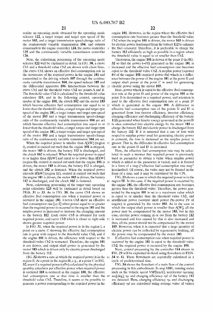
US 6,480,767 B2 21
realize an operating mode obtained by the operating mode Selector 122, a target torque and target rpm Speed of the motor 103, and a target transmission Speed-change ratio of the continuously variable transmission 104, and outputs commands to the engine controller 124, the motor controller 125 and the continuously variable transmission controller 126.
Next, the calculating processing of the operating mode selector 122 will be explained in detail. In FIG. 30, a curve Cb1 and a threshold value Cb2 are shown with chain lines. The curve Cb1 shows an effective fuel consumption rate in the occurrence of the required power in the engine 101 and transmitted to the driving wheels 107 through the continu ously variable transmission 104, the speed reducer 105 and the differential apparatus 106. Intersections between the curve Cb1 and the threshold value Cb2 are points A and B. The threshold value Cb2 is calculated by the threshold value calculator 119, and in the following control, operating modes of the engine 101, the clutch 102 and the motor 103 which become effective fuel consumption rate equal to or lower than the threshold value, a target torque and target rpm Speed of the engine 101, a target torque and target rpm Speed of the motor 103 and a target transmission Speed-change ratio of the continuously variable transmission 104 are set which become effective fuel consumption rate equal to or lower than the threshold value, a target torque and target rpm Speed of the engine 101, a target torque and target rpm Speed of the motor 103 and a target transmission Speed-change ratio of the continuously variable transmission 104 are set. When the required power is smaller than AkW (region
I), control is carried out Such that the engine 101 is stopped, the motor 103 is driven, the battery 112 is discharged, and the clutch 102 is released. When the required power is equal to or higher than AkW) and equal to or lower than BkW) (region II), control is carried out Such that the engine 101 is driven, the motor 103 is driven, the battery 112 is charged, and the clutch 102 is fastened. When the required power exceeds BkW (region III), control is carried out such that the engine 101 is driven, the motor 103 is driven, the battery 112 is discharged, and the clutch 102 is fastened.
Next, calculating processing of the target unit operating point calculator 123 will be explained in detail based on FIGS. 31 to 33. As in FIG. 30, the curve Cb1 shows an effective fuel consumption rate when a required power is occurred in the engine 101. Curves Cb3 show an effective fuel consumption rate cc/J when power equal to or greater than the required power is occurred in the engine 101 and the Surplus power is increased to increase the charging amount to the battery 112. Each curve Cb3 is obtained for each required power, and curve Cb3 which is closer to right side shows greater required power.
In FIG. 31, when the required power is in the region I, a point on a curve C showing the effective fuel consumption rate is great with respect to the threshold value Cb2, and if the engine 101 is driven, the efficiency with respect to the threshold value Cb2 is worsened. Therefore, the engine 101 is not driven, and output shaft power is generated by the motor 103 which is driven only by electric power discharged from the battery 112.
FIG. 32 shows a case in which the required power is in the region II. At a point in the region II, e.g., at a point C in FIG. 32, even if a required power (=Pn) calculated by the physical quantity calculator per effective power when required power is occurred 118 is occurred in the engine 101, the effective fuel consumption rate at that time is Smaller than the threshold value Cb2. Therefore, it seems to be possible to generate a power corresponding to the required power in the
15
25
35
40
45
50
55
60
65
22 engine 101. However, in the region where the effective fuel consumption rate becomes greater than the threshold value Cb2 when the engine 101 is driven, the motor 103 is driven by electric power discharged from the battery 112 to enhance the fuel economy. Therefore, it is preferable to charge the battery 112 efficiently as high as possible in a region where the threshold value is equal to or smaller than Cb2.
Thereupon, the engine 101 is driven at the point D in FIG. 32 so that the power (=Pd) generated in the engine 101 is increased and the effective fuel consumption rate becomes equal to the threshold value Cb2. A Surplus power (=power Pd of the engine 101-required power Pn) which is a differ ence between the power of the engine 101 at the point D and output shaft power at the point C is used for generating electric power using the motor 103.
Here, power which is equal to the effective fuel consump tion rate at the point D and power of the engine 101 at the point D is determined as a required power, and attention is paid to the effective fuel consumption rate at a point D' which is generated in the engine 101. A difference in effective fuel consumption rate of the points D and D' is generated from loss (motor efficiency, inverter efficiency, charging efficiency and discharging efficiency of the battery 112) generated when kinetic energy generated at the point D is once converted into electric energy by the motor 103 to charge the battery 112 and electric power is discharged from the battery 112. If it is assumed that a rate of loss with respect to Surplus power used for generating electric power is constant, the loSS is increased as the Surplus power is greater. That is, the difference in effective fuel consumption rate at the points D and D" is increased.
Here, the effective fuel consumption rate may be calcu lated in Such a manner that required power is previously used as parameter to obtain a value when Surplus power which is added to the parameter is varied, and it is formed in a form of a map ("effective fuel consumption rate map' hereinafter). Of course, the value may not be formed in the form of a map, and it may be calculated by the CPU. FIG.33 shows a case in which the required power is in the
region III. In this case, if the required power is occurred by the engine 101, the effective fuel consumption rate becomes greater than the threshold value. Therefore, the power gen erated by the engine 101 is set to a maximum value which is equal to or smaller than the threshold value Cb2, and insufficient power (=output shaft power Pn-power Pd of engine) is generated by the motor 103. AS in the case in which the output shaft power is smaller than AW), all the power may be compensated by the motor 103, but in this case, electric power coming in or out from the battery 112 is increased and loSS caused by this is also increased and thus, all the power should not be compensated by the motor 103. However, when it is expected that a large quantity of electric power can be collected by regenerative braking, all the power may be compensated by the motor 103.
If effective fuel consumption rate when required power is occurred by the engine 101 is equal to the threshold value Cb2, the required power is occurred by the engine 101.
Next, control processing by the controller 114 shown in FIG. 29 will be explained in detail using flowcharts in FIGS. 34 to 41. These flowcharts are repeatedly calculated in a cycle of predetermined time.
FIG. 34 shows the flowchart of a main flow of the control processing in this embodiment. In Step S101, running States Such as the vehicle speed VSPkm/h), accelerator opening accideg, mc and charging efficiency md of the battery 112 are detected. Here, charging efficiency mc and discharging efficiency md are calculated using average value of values

US 6,480,767 B2 23
obtained during past charging and discharging. These values may be calculated by learning of values when the last running is completed.
In step S102, power (output shaft power) tRdW gener ated in the output shaft is calculated to Satisfy the driving force required by the driver. In step S103, transmitting efficiency data String with respect to the transmission Speed change ratio of the continuously variable transmission cor responding to the vehicle Speed is calculated. In Step S104, operating points of the engine 101, the motor 103 and the continuously variable transmission 104 capable of realizing the output shaft power with minimum fuel consumption amount are calculated, and a physical quantity per effective power in the occurrence of the required power when the power (required power) is occurred in the engine 101 using the calculated operating points is calculated.
In step S105, a threshold value for selecting the operating mode is calculated. In step S106, the threshold value and the physical quantity per effective power in the occurrence of the required power are compared in size. In step S107, the required power and the power at the operating point of the engine 101 which minimizes the amount of fuel consumed per unit power are compared in size.
in Step S108, an operating mode is Selected based on results of comparisons in steps S106 and S107. In step S109, operating points of the engine 101, the motor 103 and the continuously variable transmission 104 realizing the Selected operating modes are calculated.
FIG. 35 is a flowchat showing detailed processing in step S102 for calculating the target output shaft power in FIG. 34. In step S111, a MAPttd (VSP, acc) is retrieved using map based on the vehicle speed VSPkm/h) and the accelerator opening acccdeg, thereby calculating the target driving torque tTcNm). FIG. 43 shows an example of a target driving torque calculating map MAPttd (VSP, acc). This map is formed in Such a manner that a driving force tTod required by the driver is estimated from the vehicle speed VSP and the accelerator opening acc at that time, and the estimated value tTod is formed in a form of a map. A dynamic compensation may be added to the target driving torque tTod by a variation limit or temporarily delay element for enhanc ing the driving performance after map retrieving.
In step S122, a target output shaft power t?dW) is calculated by the following equation 4 based on the vehicle speed VSP, the target driving torque tTcl and tire effective radius rim.
10 tion 4 tPn = (Td VSP. r. Equation 4
FIG. 36 is a flowchart showing detailed processing in Step S104 for calculating a physical quantity per effective power in the occurrence of the required power in FIG. 34. In step S121, an rpm speed upper limit value Nilurpm and an rpm speed lower limit value NiL rpm are obtained from a table TBLcvtu(VSP) associated with an upper limit value of the engine rpm speed Nirpm which can be taken in accordance with the vehicle speed VSP and from a table TBLcvtl(VSP) asSociated with a lower limit value. For example, if a range of the engine rpm Speed which can be taken by limitation of the continuously variable transmission 104 is determined as shown in FIG. 44, the following associations are taken: Ni10=TBLcvtl(VSPO), NiU=TBLevtu(VSP0).
In Step S122, as the engine rpm Speed for calculating the fuel consumption amount in the Subsequent processing, strings NiSn) (n is number of strings which is determined by NiL and NiU) which are divided every 50rpm) from the
15
25
35
40
45
50
55
60
65
24 rpm Speed lower limit value NiL to the rpm Speed upper limit value NiO are formed, and i is set to 0.
In step S123, i is incremented by one, and if i>n is not established, procedure is proceeded to Step S124, and if i>n is established, the processing is proceeded to Step S127.
In steps S124 to 126, a fuel consumption amount FuelSi of the engine 101 when engine rpm speed NiSi is taken is calculated. First, in Step S124, a transmission Speed-change ratio RcvtS of the continuously variable transmission 104 is obtained from the following equation 5 based on the vehicle speed VSP, the engine rpm speed NiSi and the tire effective radius rim.
Equation 5 RotS =
..., 36 Nis(i)
Then, a continuously variable transmission input torque TcvtSNm) is obtained using a map MAPcvt(tTd, RcvtS, NiSil) of the continuously variable transmission input torque capable of realizing a target driving torque by cor recting loSS torque in the continuously variable transmission 104 from a target driving torque tTod, a transmission Speed change ratio RcvtS and the engine rpm speed NiSrpm.
In Subsequent step S125, the continuously variable trans mission input torque TcvtS is defined as the engine torque TeS. In step S126, a fuel consumption amount FuelSi of the engine 101 is retrieved using MAPfuel(TeS, NiSil) which is a function of the engine torque TeS and the engine rpm speed NiSi). FIG. 42 shows one example of the MAPfuel(TeS, NiSi).
If the processing in steps S124 to 126 for the number n of Strings is completed, in step S127, a string order having the Smallest value among the fuel consumption amount Fuel Si of the engine 101 corresponding to the engine rpm Speed NiSi of all of i=1 to n is selected. In step S128, an operating point (torque: tTenNm), rpm speed. tNenrpm when power (required power) of the engine 101 which realizes the output shaft power is generated is calculated.
In step S129, a physical quantity Vincc/J per effective power in the occurrence of the required power is obtained by the following equation 6.
Fuel Si tTei. iN 27t
e e 60
Eduation 6 W = Equation 6
FIG.37 is a flowchart showing detailed processing in step 105 for calculating a threshold value to select the operating mode in FIG. 34. In step S131, a threshold value Vccc/J for Selecting an operating mode calculated in the last calculating cycle is defined as Vccc./J
In Subsequent Step S132, proportion control is carried out based on deviation between a target SOC value tSOC% (e.g., SOC=50%) and the SOC value SOCI% of the battery 112, and the threshold value Vccc/J is calculated. Here, the threshold value Vc is calculated using the follow ing equation 7.
Vc=K(tSOC-SOC)+Vc Equation 7
A value which was previously obtained by experiment is used for the constant K in this equation 7.
FIG. 38 is a flowchart indicating detailed processing in step S106 which compares the threshold value and the physical quantity per effective power in the occurrence of the required power in size. In step S141, the threshold value
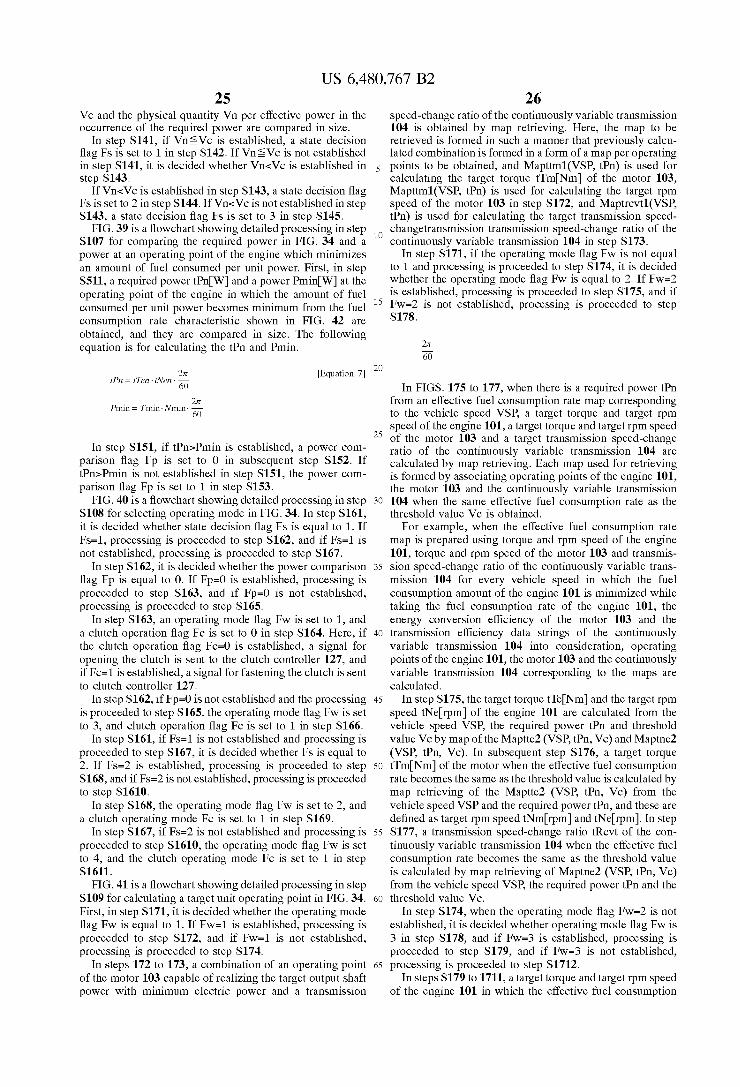
US 6,480,767 B2 25
Vc and the physical quantity Vn per effective power in the occurrence of the required power are compared in size.
In step S141, if Vns Vc is established, a state decision flag Fs is set to 1 in step S142. If Vns Vc is not established in step S141, it is decided whether Vn-Vc is established in step S143.
If Vn-Vc is established in step S143, a state decision flag Fs is set to 2 in step S144. If Vn<Vc is not established in step S143, a state decision flag Fs is set to 3 in step S145.
FIG. 39 is a flowchart showing detailed processing in step S107 for comparing the required power in FIG. 34 and a power at an operating point of the engine which minimizes an amount of fuel consumed per unit power. First, in Step S511, a required power tRnW and a power PminW at the operating point of the engine in which the amount of fuel consumed per unit power becomes minimum from the fuel consumption rate characteristic shown in FIG. 42 are obtained, and they are compared in size. The following equation is for calculating the t?n and Pmin.
2 tion 7 ten = (Ten INen. Equation 7 60
in = Timin. Nmi 27t Pmin = Timin. Nmin 60
In step S151, if t?n>Pmin is established, a power com parison flag Fp is set to 0 in Subsequent step S152. If tPn>Pmin is not established in step S151, the power com parison flag Fp is set to 1 in step S153.
FIG. 40 is a flowchart showing detailed processing in step S108 for selecting operating mode in FIG. 34. In step S161, it is decided whether State decision flag FS is equal to 1. If FS=1, processing is proceeded to Step S162, and if FS=1 is not established, processing is proceeded to Step S167.
In step S162, it is decided whether the power comparison flag Fp is equal to 0. If Fp=0 is established, processing is proceeded to step S163, and if Fp=0 is not established, processing is proceeded to Step S165.
In Step S163, an operating mode flag Fw is set to 1, and a clutch operation flag Fc is set to 0 in step S164. Here, if the clutch operation flag Fc=0 is established, a Signal for opening the clutch is Sent to the clutch controller 127, and if Fc=1 is established, a Signal for fastening the clutch is sent to clutch controller 127.
In step S162, if Fp=0 is not established and the processing is proceeded to Step S165, the operating mode flag Fw is Set to 3, and clutch operation flag Fc is set to 1 in step S166.
In step S161, if FS=1 is not established and processing is proceeded to step S167, it is decided whether Fs is equal to 2. If FS=2 is established, processing is proceeded to Step S168, and if Fs=2 is not established, processing is proceeded to step S1610.
In step S168, the operating mode flag Fw is set to 2, and a clutch operating mode Fc is set to 1 in step S169.
In step S167, if FS=2 is not established and processing is proceeded to step S1610, the operating mode flag Fw is set to 4, and the clutch operating mode Fc is Set to 1 in Step S1611.
FIG. 41 is a flowchart showing detailed processing in Step S109 for calculating a target unit operating point in FIG. 34. First, in step S171, it is decided whether the operating mode flag Fw is equal to 1. If Fw-1 is established, processing is proceeded to step S172, and if Fw-1 is not established, processing is proceeded to Step S174.
In steps 172 to 173, a combination of an operating point of the motor 103 capable of realizing the target output shaft power with minimum electric power and a transmission
15
25
35
40
45
50
55
60
65
26 Speed-change ratio of the continuously variable transmission 104 is obtained by map retrieving. Here, the map to be retrieved is formed in Such a manner that previously calcu lated combination is formed in a form of a map per operating points to be obtained, and Mapttm1(VSP, tFn) is used for calculating the target torque tTm Nm of the motor 103, Mapttm1(VSP, tRn) is used for calculating the target rpm speed of the motor 103 in step S172, and Maptrevt1(VSP tPn) is used for calculating the target transmission speed changetransmission transmission Speed-change ratio of the continuously variable transmission 104 in step S173.
In step S171, if the operating mode flag Fw is not equal to 1 and processing is proceeded to Step S174, it is decided whether the operating mode flag Fw is equal to 2. If Fw-2 is established, processing is proceeded to Step S175, and if Fw=2 is not established, processing is proceeded to Step S178.
27t 60
In FIGS. 175 to 177, when there is a required power tBn from an effective fuel consumption rate map corresponding to the vehicle Speed VSP, a target torque and target rpm Speed of the engine 101, a target torque and target rpm Speed of the motor 103 and a target transmission Speed-change ratio of the continuously variable transmission 104 are calculated by map retrieving. Each map used for retrieving is formed by associating operating points of the engine 101, the motor 103 and the continuously variable transmission 104 when the same effective fuel consumption rate as the threshold value Vc is obtained.
For example, when the effective fuel consumption rate map is prepared using torque and rpm Speed of the engine 101, torque and rpm speed of the motor 103 and transmis Sion Speed-change ratio of the continuously variable trans mission 104 for every vehicle speed in which the fuel consumption amount of the engine 101 is minimized while taking the fuel consumption rate of the engine 101, the energy conversion efficiency of the motor 103 and the transmission efficiency data Strings of the continuously variable transmission 104 into consideration, operating points of the engine 101, the motor 103 and the continuously variable transmission 104 corresponding to the maps are calculated.
In step S175, the target torque tTeNm) and the target rpm speed tNerpm of the engine 101 are calculated from the vehicle speed VSP, the required power t?n and threshold value Vc by map of the Maptte2(VSP, tRn, Vc) and Maptne2 (VSP, tRn, Vc). In Subsequent step S176, a target torque tTmINm of the motor when the effective fuel consumption rate becomes the same as the threshold value is calculated by map retrieving of the Maptte2 (VSP, tFn, Vc) from the vehicle speed VSP and the required power t?n, and these are defined as target rpm speed tNm rpm and tNerpm. In Step S177, a transmission speed-change ratio tRcvt of the con tinuously variable transmission 104 when the effective fuel consumption rate becomes the same as the threshold value is calculated by map retrieving of Maptne2 (VSP, tFn, Vc) from the vehicle speed VSP, the required power tRn and the threshold value Vc.
In step S174, when the operating mode flag Fw=2 is not established, it is decided whether operating mode flag Fw is 3 in step S178, and if Fw–3 is established, processing is proceeded to step S179, and if Fw–3 is not established, processing is proceeded to Step S1712.
In steps S179 to 1711, a target torque and target rpm speed of the engine 101 in which the effective fuel consumption

US 6,480,767 B2 27
rate becomes equal to the threshold value Vc corresponding to the vehicle Speed VSP, a target torque and target rpm Speed of the motor 103, and a target transmission Speed change ratio of the continuously variable transmission 104 are calculated by map retrieving from the effective fuel consumption rate map when various required powers are occurred in each vehicle Speed. Each map used for retrieving is formed by associating operating points of the engine 101, the motor 103 and the continuously variable transmission 104 when the same effective fuel consumption rate as the threshold value Vc is obtained at the time of generation of the required power.
For example, when the effective fuel consumption rate map at the time of generation of the required power is prepared using torque and rpm Speed of the engine 101, torque and rpm Speed of the motor 103 and transmission Speed-change ratio of the continuously variable transmission 104 for every vehicle speed in which the fuel consumption amount of the engine 101 is minimized while taking the fuel consumption rate of the engine 101, the energy conversion efficiency of the motor 103 and the transmission efficiency data strings of the continuously variable transmission 104 into consideration, operating points of the engine 101, the motor 103 and the continuously variable transmission 104 corresponding to the maps are calculated.
First, in step S179, the target torque tTe and the target rpm speed tNe of the engine 101 are calculated by map retrieving using the Maptte3(VSP, Vc) and Maptne3(VSP, Vc) from the vehicle speed VSP and the threshold value Vc. In Subsequent Step S170, a target transmission Speed-change ratio tRcvt of the continuously variable transmission 104 is calculated by map retrieving of Maptrevt3(VSP, tRn) from the vehicle speed VSP and the required power t?n. In step S1711, power tRgW when the target torque tTe and the target rpm Speed tNe of the engine 101 are generated are calculated by the following equation 9.
27t tion 9 tFg = t Te. twe. 60 Equation 9
Further, a transmission efficiency mn cvt continuously variable transmission in the continuously variable transmis sion 104 is calculated by the following equation 10.
iPad
Te. iNe. -- tle: Ive.
Equation 10 incvt =
Based on a result of the above calculation, a target torque tTm and the target rpm speed tNm of the motor in which the required power fuel consumption rate becomes equal to the threshold value Vc corresponding to the vehicle speed VSP are calculated by the following equation 11.
tPad, incvt - tig Equation 11 iTi = - - -
1Ne. 60
iWin = iNe
In step S178, if the operating mode flag Fw is not 3, in steps S1712 to 1714, a target torque and target rpm speed of the engine 101 in which the effective fuel consumption rate at the time of generation of the required power becomes equal to the threshold value Vc, a target torque and target rpm Speed of the motor 103, and a target transmission Speed-change ratio of the continuously variable transmission
15
25
35
40
45
50
55
60
65
28 104 are calculated by map retrieving from the effective fuel consumption rate map corresponding to the vehicle Speed VSP when the effective fuel consumption rate at the time of generation of the required power becomes equal to the threshold value Vc.
First, in step S1712, the target torque tTeNm) and the target rpm speed tNerpm of the engine 101 are calculated by map retrieving using the Maptte2(VSP, tRn, Vc) and Maptne2(VSP, tBn, Vc) from the vehicle speed VSP and the threshold value Vc. Here, the Maptre2(VSP, tpu, Vc) and Maptne2(VSP, tRn, Vc) are the same as those used for map retrieving in step S175.
In step S1713, the target torque tTeNm of the engine 101 is calculated from the vehicle speed VSP, the required power tPn and threshold value Vc by map retrieving of the Mapttm2 (VSP, tRn, Vc), and the target rpm speed tNmn rpm) is defined as tNerpm). Here, the Mapttm2 (VSP, tRn, Vc) is the same as that used for map retrieving in step S176. In step S1714, the transmission speed-change ratio tRcvt of the continuously variable transmission 104 is calculated by map retrieving of Maptrevt2 (VSP, tRn, Vc) from the vehicle speed VSP, required power tRn and threshold value Vc.
According to the above embodiment, a threshold value and a predetermined physical quantity concerning the engine 101 per effective power with respect to a sum of power of the output shaft calculate while taking energy conversion efficiency of the engine 101, the motor 103 and the con tinuously variable transmission 104, and power of the engine 101 at which electric power generated while taking the energy conversion efficiency of the engine 101, the motor 103 and the battery 112 once charged into the battery 112 and is used for generating electric power that can be consumed for the future discharging are compared, and operating mode of the engine 101 and the motor 103 at the time of running and operating points of the engine 101, the motor 103 and the continuously variable transmission 104 are determined and thus, it is possible to further optimize a predetermined physical quantity concerning the engine 101.
This point will be explained while taking, as an example, a case in which fuel consumption amount of the engine 101 is reduced, using FIG. 45. In FIG. 45, a curve shown with broken line shows effective fuel consumption rate cc/J which is fuel consumption amount per effective power rate when required power is occurred in the engine 101 at a certain vehicle Speed. A physical quantity per effective power in the occurrence
of the required power in this embodiment is shown with the broken line Cb11. Solid lines Cb12 are curves showing effective fuel consumption rate when power equal to or greater than required power is occurred in the engine 101 and Surplus power to be charged into the battery 112 is increased. The Solid lines are obtained for each required power, and line which is closer to right Side shows higher load having greater required power.
In the related art, a power equal to or greater than a required power at the time of a certain required power is occurred in the engine, and effective fuel consumption rate when the Surplus to be charged into the battery is increased is compared, an operating mode, and operating points of the engine, the motor and the transmission which correspond when the value becomes minimum are calculated.
That is, operating mode and each operating point having best efficiency within a range at the time of certain required power are calculated. For example, when the required power is C1, an effective fuel consumption rate when power of the engine which is Surplus equal to or greater than the required power is changed is shown with a curve C. In the related art,

US 6,480,767 B2 29
an operating mode which generates the required power by the engine is Selected, required power or higher power is occurred at the point C2, and electric power generated using the power of the Surplus engine is charged into the battery. When the required power is C1, an operating mode using the engine as a power Source for running is Selected, only power corresponding to a required power B1 at which the efficiency in the engine becomes highest is generated, and the battery is not charged. If attention is paid to the Selected C2 and 31, the point C2 Surely has best efficiency at the time of the required power.
However, when the same electric power is charged, it is apparent that efficiency is higher when electric power is generated at the interSection B2 between a curve B when the required power is B1 and a curve formed when the charging electric power shown with a chain line Cb13 is the same. At the point B1, electric power is not generated although electric power can be generated efficiently as described when attention is paid to C2.
This is because that when the required power is C1, when the required power is C1, C1 and C2 are compared, and C2 having higher efficiency is Selected, and Similarly, when the required power is Y1, Y2 is Selected, and the required power is B1, 31 is Selected So that a point having best efficiency in the range of the required power during the current running is Selected. As a result, the electric power is charged in a low efficiency State. That is, in the related art, an operating mode always capable of minimizing the fuel consumption amount throughout the entire running State is not Selected.
Further, in the related art, it is not possible to Select an operating mode controlling the efficiency to a predetermined value. More specifically, Since the object to be compared (efficiency in a range of required power during current running State) when high efficiency is Selected is largely varied in accordance with the required power, the efficiency of the Selected operating mode is not efficiency which is previously Set by a designer or the like, and value is varied at every required power.
Whereas, in this embodiment, the operating mode is Selected using absolute criteria which are threshold values concerning the fuel consumption amount Set by the designer. Therefore, under a normal condition, when charging is not required in a hurry, the threshold value is Set Such that the efficiency is enhanced as high as possible to generate electric power in which efficiency is enhanced. When the electric power is charged in a low efficient State, this is limited to a case in which a designer's will to charge even if the efficiency is low is reflected to the threshold value, and its amount is set to be minimum. When the efficiency is lowered if the engine 101 is driven, although it depends on the Setting of the threshold value, the motor 103 is driven by electric power from the battery 112 charged with electric power in the efficient State to avoid generation of electric power in a low efficiency State, which makes it possible to reduce the fuel consumption amount.
Further, the threshold value is set by will of the designer to control the efficiency, and the operating mode of running can be selected with effective fuel consumption rate which is equal to or lower than the threshold value. Therefore, it is possible to set the threshold value to the effective fuel consumption rate as Small as possible within a range causing no problem for running, and to reduce the fuel consumption amount more effectively. Further, when a physical quantity per effective power is defined as exhaust gas amount per effective power rate in the engine, it is possible to reduce the exhaust gas amount as compared with the related art.
Further, a designer who applies the present invention only need to use the calculation method of a threshold value. With
15
25
35
40
45
50
55
60
65
30 this operation, the operating mode or target generated elec tric power can be determined uniquely in accordance with the running State, and a System can be designed with high visibility.
In the above embodiment, physical quantity per effective power can be made as exhaust gas component to be limited per power in the engine, which makes it possible to reduce the exhaust gas component with respect to the power of the engine as compared with the related art.
Further, by comparing the threshold value and the physi cal quantity per effective power with respect to the required power, it is possible to Select operating mode which is equal to or better than the threshold value. More Specifically, in the first operating mode, output shaft
power is generated by the motor 103. Thus, driving for reducing the efficiency with respect to the threshold value is not carried out in the engine 101, and the physical quantity per effective power at that time is more excellent with respect to the threshold value. In the Second operating mode, driving having efficiency equal to or higher than the thresh old value is carried out in the engine 101, power of the engine 101 equal to or higher than the required power is occurred, and electric power is generated by power of the engine 101 which is surplus is charged into the battery 112. Therefore, driving is not carried out in a State where the efficiency with respect to the threshold value is lower is not carried out in the engine 101 like the first or third operating mode, and the vehicle can run with the motor 103 using electric power charged with high efficiency in the Second operating mode.
In the third operating mode, the power of the engine 101 is efficiently generated Such that maximum required power equal to or lower than the threshold value is obtained, and insufficient power with respect to the required power is occurred by the motor. Thus, physical quantity per effective power at that time is equal to the threshold value. AS compared with a case in which all the required power is occurred by the motor 103 in a relatively high load, since a large quantity of electricity is not discharged at once from the battery 112, it is possible to Suppress the abrupt rise of temperature and deterioration of performance of the battery 112, and to reduce the battery 112 in size.
In the fourth operating mode, required power is occurred in the engine 101, and the vehicle can run with efficiency equal to the threshold value.
Further, according to the present embodiment, the oper ating points of the engine 101, the motor 103 and the continuously variable transmission 104 used for calculating physical quantity per effective power are calculated Such that a driving force required by the driver and the power of the engine 101 in the various required power and various power of the engine 101 are calculated Such that a prede termined physical quantity concerning the engine 101 is minimized. Therefore, operating mode calculated based on the physical quantity per effective power and the operating points of the engine 101, the motor 103 and the continuously variable transmission 104, as well as a predetermined physi cal quantity concerning the engine 101 can be set Suitably.
In the above embodiment, the belt type continuously variable transmission 104 is used, and the one motor 103 controls the Starting, electric power generation, running and regenerative braking of the engine 101. Alternatively, the present invention can also be applied to the above-described transmission (toroidal type continuously variable transmission, continuously variable transmission using the above-described planetary gear and transmission for chang ing Speed Stepwisely) or a hybrid vehicle using two motors.
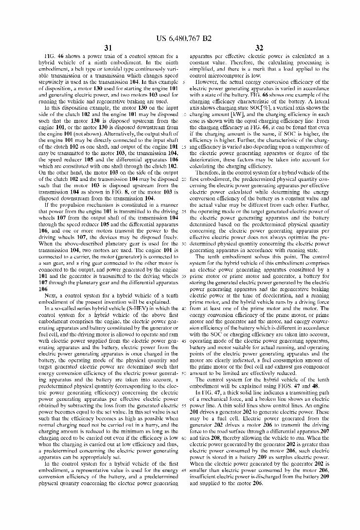
US 6,480,767 B2 31
FIG. 46 shows a power train of a control system for a hybrid vehicle of a ninth embodiment. In the ninth embodiment, a belt type or toroidal type continuously vari able transmission or a transmission which changes Speed Stepwisely is used as the transmission 104. In this example of disposition, a motor 130 used for starting the engine 101 and generating electric power, and two motorS 103 used for running the vehicle and regenerative braking are used.
In this disposition example, the motor 130 on the input side of the clutch 102 and the engine 101 may be disposed such that the motor 130 is disposed upstream from the engine 101, or the motor 130 is disposed downstream from the engine 101 (not shown). Alternatively, the output shaft of the engine 101 may be directly connected to the input shaft of the clutch 102 as one shaft, and output of the engine 101 may be transmitted to the motor 103, the transmission 104, the speed reducer 105 and the differential apparatus 106 which are constituted with one shaft through the clutch 102. On the other hand, the motor 103 on the side of the output of the clutch 102 and the transmission 104 may be disposed such that the motor 103 is disposed upstream from the transmission 104 as shown in FIG. 8, or the motor 103 is disposed downstream from the transmission 104.
If the propulsion mechanism is constituted in a manner that power from the engine 101 is transmitted to the driving wheels 107 from the output shaft of the transmission 104 through the speed reducer 105 and the differential apparatus 106, and one or more motors transmit the power to the driving wheels 107, the devices may be disposed freely. When the above-described planetary gear is used for the transmission 104, two motors are used. The engine 101 is connected to a carrier, the motor (generator) is connected to a Sun gear, and a ring gear connected to the other motor is connected to the output, and power generated by the engine 101 and the generator is transmitted to the driving wheels 107 through the planetary gear and the differential apparatus 106.
Next, a control system for a hybrid vehicle of a tenth embodiment of the present invention will be explained.
In a so-called series hybrid vehicle (S-HEV) in which the control system for a hybrid vehicle of the above first embodiment comprises the engine, the electric power gen erating apparatus and battery constituted by the generator or fuel cell, and the driving motor is allowed to operate and ram with electric power Supplied from the electric power gen erating apparatus and the battery, electric power from the electric power generating apparatus is once charged in the battery, the operating mode of the physical quantity and target generated electric power are determined Such that energy conversion efficiency of the electric power generat ing apparatus and the battery are taken into account, a predetermined physical quantity (corresponding to the elec tric power generating efficiency) concerning the electric power generating apparatus per effective electric power obtained by Subtracting the loSS from the generated electric power becomes equal to the Set value. In this Set value is Set Such that the efficiency becomes as high as possible when normal charging need not be carried out in a hurry, and the charging amount is reduced to the minimum as long as the charging need to be carried out even if the efficiency is low when the charging is carried out at low efficiency and thus, a predetermined concerning the electric power generating apparatus can be appropriately Set.
In the control system for a hybrid vehicle of the first embodiment, a representative value is used for the energy conversion efficiency of the battery, and a predetermined physical quantity concerning the electric power generating
15
25
35
40
45
50
55
60
65
32 apparatus per effective electric power is calculated as a constant value. Therefore, the calculating processing is Simplified, and there is a merit that a load applied to the control microcomputer is low.
However, the actual energy conversion efficiency of the electric power generating apparatus is varied in accordance with a state of the battery. FIG. 66 shows one example of the charging efficiency characteristic of the battery. A lateral axis shows charging State SOC%), a vertical axis shows the charging amount kW), and the charging efficiency in each case is shown with the equal charging efficiency line. From the charging efficiency in FIG. 66, it can be found that even if the charging amount is the same, if SOC is higher, the efficiency is higher. Further, the characteristic of the charg ing efficiency is varied also depending upon a temperature of the electric power generating apparatus or degree of the deterioration, these factors may be taken into account for calculating the charging efficiency.
Therefore, in the control system for a hybrid vehicle of the first embodiment, the predetermined physical quantity con cerning the electric power generating apparatus per effective electric power calculated while determining the energy conversion efficiency of the battery as a constant value and the actual value may be different from each other. Further, the operating mode or the target generated electric power of the electric power generating apparatus and the battery determined based on the predetermined physical quantity concerning the electric power generating apparatus per effective electric power does not always optimize the pre determined physical quantity concerning the electric power generating apparatus in accordance With running State. The tenth embodiment solves this point. The control
System for the hybrid vehicle of this embodiment comprises an electric power generating apparatus constituted by a prime motor or prime motor and generator, a battery for Storing the generated electric power generated by the electric power generating apparatus and the regenerative braking electric power at the time of deceleration, and a running prime motor, and the hybrid vehicle runs by a driving force from at least one of the prime motor and the motor. The energy conversion efficiency of the prime motor, or prime motor and the generator and the motor, and energy conver sion efficiency of the battery which is different in accordance with the SOC or charging efficiency are taken into account, operating mode of the electric power generating apparatus, battery and motor Suitable for actual running, and operating points of the electric power generating apparatus and the motor are clearly indicated, a fuel consumption amount of the prime motor or the fuel cell and exhaust gas component amount to be limited are effectively reduced. The control system for the hybrid vehicle of the tenth
embodiment will be explained using FIGS. 47 and 48. In FIG. 47, a thick solid line indicates a transmitting path
of a mechanical force, and a broken line shows an electric power line. A thin Solid lines show control lines. An engine 201 drives a generator 202 to generate electric power. These may be a fuel cell. Electric power generated from the generator 202 drives a motor 206 to transmit the driving force to the road surface through a differential apparatus 207 and tires 208, thereby allowing the vehicle to run. When the electric power generated by the generator 202 is greater than electric power consumed by the motor 206, such electric power is stored in a battery 209 as surplus electric power. When the electric power generated by the generator 202 is smaller than electric power consumed by the motor 206, insufficient electric power is discharged from the battery 209 and supplied to the motor 206.
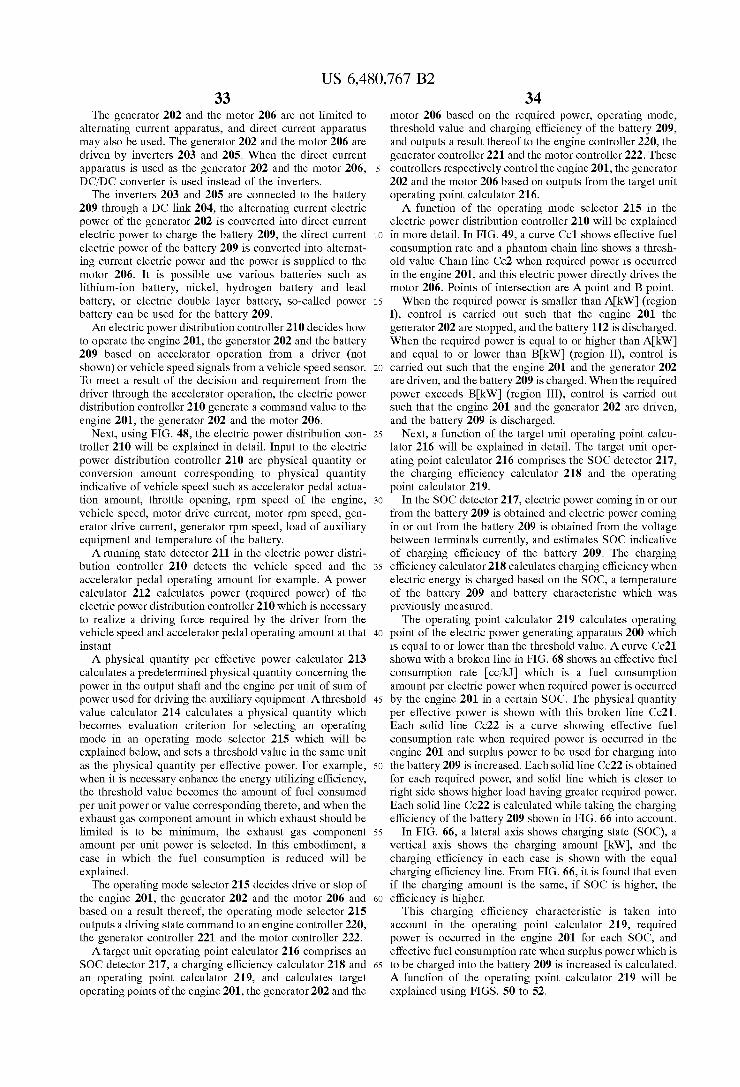
US 6,480,767 B2 33
The generator 202 and the motor 206 are not limited to alternating current apparatus, and direct current apparatus may also be used. The generator 202 and the motor 206 are driven by inverters 203 and 205. When the direct current apparatus is used as the generator 202 and the motor 206, DC/DC converter is used instead of the inverters. The inverters 203 and 205 are connected to the battery
209 through a DC link 204, the alternating current electric power of the generator 202 is converted into direct current electric power to charge the battery 209, the direct current electric power of the battery 209 is converted into alternat ing current electric power and the power is Supplied to the motor 206. It is possible use various batteries such as lithium-ion battery, nickel, hydrogen battery and lead battery, or electric double layer battery, So-called power battery can be used for the battery 209. An electric power distribution controller 210 decides how
to operate the engine 201, the generator 202 and the battery 209 based on accelerator operation from a driver (not shown) or vehicle speed signals from a vehicle speed sensor. To meet a result of the decision and requirement from the driver through the accelerator operation, the electric power distribution controller 210 generate a command value to the engine 201, the generator 202 and the motor 206.
Next, using FIG. 48, the electric power distribution con troller 210 will be explained in detail. Input to the electric power distribution controller 210 are physical quantity or conversion amount corresponding to physical quantity indicative of vehicle Speed Such as accelerator pedal actua tion amount, throttle opening, rpm Speed of the engine, vehicle Speed, motor drive current, motor rpm Speed, gen erator drive current, generator rpm Speed, load of auxiliary equipment and temperature of the battery. A running State detector 211 in the electric power distri
bution controller 210 detects the vehicle speed and the accelerator pedal operating amount for example. A power calculator 212 calculates power (required power) of the electric power distribution controller 210 which is necessary to realize a driving force required by the driver from the vehicle Speed and accelerator pedal operating amount at that instant. A physical quantity per effective power calculator 213
calculates a predetermined physical quantity concerning the power in the output shaft and the engine per unit of Sum of power used for driving the auxiliary equipment. A threshold value calculator 214 calculates a physical quantity which becomes evaluation criterion for Selecting an operating mode in an operating mode selector 215 which will be explained below, and Sets a threshold value in the same unit as the physical quantity per effective power. For example, when it is necessary enhance the energy utilizing efficiency, the threshold value becomes the amount of fuel consumed per unit power or value corresponding thereto, and when the exhaust gas component amount in which exhaust should be limited is to be minimum, the exhaust gas component amount per unit power is Selected. In this embodiment, a case in which the fuel consumption is reduced will be explained.
The operating mode selector 215 decides drive or stop of the engine 201, the generator 202 and the motor 206 and based on a result thereof, the operating mode Selector 215 outputs a driving State command to an engine controller 220, the generator controller 221 and the motor controller 222. A target unit operating point calculator 216 comprises an
SOC detector 217, a charging efficiency calculator 218 and an operating point calculator 219, and calculates target operating points of the engine 201, the generator 202 and the
15
25
35
40
45
50
55
60
65
34 motor 206 based on the required power, operating mode, threshold value and charging efficiency of the battery 209, and outputs a result thereof to the engine controller 220, the generator controller 221 and the motor controller 222. These controllerS respectively control the engine 201, the generator 202 and the motor 206 based on outputs from the target unit operating point calculator 216. A function of the operating mode selector 215 in the
electric power distribution controller 210 will be explained in more detail. In FIG. 49, a curve Col shows effective fuel consumption rate and a phantom chain line shows a thresh old value Chain line Ce2 when required power is occurred in the engine 201, and this electric power directly drives the motor 206. Points of intersection are A point and B point. When the required power is smaller than AkW (region
I), control is carried out such that the engine 201 the generator 202 are stopped, and the battery 112 is discharged. When the required power is equal to or higher than AkW) and equal to or lower than BkW (region II), control is carried out such that the engine 201 and the generator 202 are driven, and the battery 209 is charged. When the required power exceeds BkW (region III), control is carried out such that the engine 201 and the generator 202 are driven, and the battery 209 is discharged.
Next, a function of the target unit operating point calcu lator 216 will be explained in detail. The target unit oper ating point calculator 216 comprises the SOC detector 217, the charging efficiency calculator 218 and the operating point calculator 219.
In the SOC detector 217, electric power coming in or our from the battery 209 is obtained and electric power coming in or out from the battery 209 is obtained from the voltage between terminals currently, and estimates SOC indicative of charging efficiency of the battery 209. The charging efficiency calculator 218 calculates charging efficiency when electric energy is charged based on the SOC, a temperature of the battery 209 and battery characteristic which was previously measured. The operating point calculator 219 calculates operating
point of the electric power generating apparatus 200 which is equal to or lower than the threshold value. A curve Ce21 shown with a broken line in FIG. 68 shows an effective fuel consumption rate cc/kJ which is a fuel consumption amount per electric power when required power is occurred by the engine 201 in a certain SOC. The physical quantity per effective power is shown with this broken line Ce21. Each solid line Ce22 is a curve showing effective fuel consumption rate when required power is occurred in the engine 201 and Surplus power to be used for charging into the battery 209 is increased. Each solid line Ce22 is obtained for each required power, and Solid line which is closer to right Side shows higher load having greater required power. Each Solid line Ce22 is calculated while taking the charging efficiency of the battery 209 shown in FIG. 66 into account.
In FIG. 66, a lateral axis shows charging state (SOC), a vertical axis shows the charging amount kW), and the charging efficiency in each case is shown with the equal charging efficiency line. From FIG. 66, it is found that even if the charging amount is the same, if SOC is higher, the efficiency is higher.
This charging efficiency characteristic is taken into account in the operating point calculator 219, required power is occurred in the engine 201 for each SOC, and effective fuel consumption rate when Surplus power which is to be charged into the battery 209 is increased is calculated. A function of the operating point calculator 219 will be explained using FIGS. 50 to 52.

US 6,480,767 B2 35
In FIG.50, the curve Ce1 shown with the phantom chain line shows an effective fuel consumption rare when electric power is directly distributed. Each solid line Ce3 shows an effective fuel consumption rate when Surplus electric power with respect to the required power is occurred when the required power in a certain SOC is a predetermined value and the Surplus electric power is increased. Each Solid line Cc3 is obtained for each required power, and Solid line which is closer to right Side shows higher load having greater required power.
If a point when the required power is directly distributed is in the region I, the curve Ce1 showing the effective fuel consumption rate is greater than the threshold value Cc2, and if the engine 201 is driven the efficiency is deteriorated with respect to the threshold value. Therefore, the engine 201 is not driven, and the motor 206 is driven by electric power discharged from the battery 209 to generate the driving power.
FIG. 51 shows a case in which a point when the required power is directly distributed is in the region II. At a point in the region II, e.g., a point C in the drawing, the effective fuel consumption rate Cel when the electric power is directly distributed is Smaller than the threshold value Ce2. Therefore, it seems possible to directly distribute the electric power at the point C. However, in a region where the effective fuel consumption rate Cell becomes greater than the threshold value CC2 when the engine 201 is driven, the motor 206 is driven by electric power discharged from the c209 to enhance the fuel economy. Thus, it is preferable that to charge the battery 209 with electricity as efficiently as possible in a region where even if the electric power is directly distributed in the region II, the value becomes lower than the threshold value Cc2. Thereupon, the power (=Pd) generated in the engine 201 is increased to drive the engine 201 at a point D in the drawing in which the effective fuel consumption rate becomes equal to the threshold value.
In this case, a Surplus power (=power Pd of the engine 201-required power Pn) which is a difference between the power of the engine 201 at the point D and output shaft power at the point C is used for charging into the battery 209. Here, power which is equal to the effective fuel consumption rate at the point D and power of the engine 201 at the point D is determined as a required power, and attention is paid to the effective fuel consumption rate at a point D' which is generated in the engine 201. A difference in effective fuel consumption rate of the points D and D' is generated from loss (motor efficiency, inverter efficiency, charging efficiency and discharging efficiency of the battery) generated when kinetic energy generated at the point D is once converted into electric energy by the generator 202. If it is assumed that a rate of loSS with respect to Surplus power used for generating electric power is constant, the loSS is increased as the Surplus power is greater. That is, the difference in effective fuel consumption rate at the points D and D" is increased.
Here, the effective fuel consumption rate may be calcu lated in Such a manner that required power is previously used as parameter to obtain a value when Surplus power which is added to the parameter is varied, and it is formed in a form of a map (“effective fuel consumption rate map' hereinafter). Of course, the value may not be formed in the form of a map, and it may be calculated by the CPU.
FIG. 52 shows a case in which a point when the required power is directly distributed is in the region III. In this case, if the required power is occurred by the engine 201, the effective fuel consumption rate Cell becomes greater than the threshold value Ce2. Therefore, the power generated by
15
25
35
40
45
50
55
60
65
36 the engine 201 is set to a maximum value which is equal to or Smaller than the threshold value Cc2, and insufficient power is compensated by discharged electric power from the battery 209. As in the case in which the output shaft power is smaller than AkW), all the power may be compensated by electric power discharged from the battery 209, but in this case, electric power coming in or out from the battery 209 is increased and loSS caused by this is also increased and thus, all the power should not be compensated by the battery 209. However, when it is expected that a large quantity of electric power can be collected by regenerative braking, all the power may be compensated by the battery 209.
If effective fuel consumption rate Ce1 when required power is directly distributed is equal to the threshold value Cc2, the required power is occurred by the engine 201. An operating point of a target operating point calculator
321 in an eleventh embodiment which will be described later can be determined in the same manner as that of the target unit operating point calculator 219 of the tenth embodiment by taking the transmission efficiency of the transmission 304 when the effective fuel consumption rate is calculated into acCOunt.
Next, a control of this embodiment will be explained based on flowcharts in FIGS. 53 to 60. FIG. 53 is a flowchart showing the flow of the entire control of this embodiment.
In Step S201, Signals indicative of vehicle States Such as accelerator pedal actuation amount 0adeg, vehicle speed VSPkm/h), the rpm speed of motor Nimrpm), the auxiliary equipment power PakW are read.
In step S202, power (required power) of the engine 201 required for running is calculated from the driving force power required by the driver and auxiliary equipment power required for driving the auxiliary equipment. In Step S203, a fuel consumption rate per unit of a Sum of the driving power and the auxiliary equipment power in the occurrence of the required power is calculated as a physical quantity per effective power. In step S204, a threshold value for deter mining the operating mode is calculated. In Step S205, operating modes of the engine 201, the generator 202 and the battery 209 are determined.
In step S206, the charging state SOC is detected. In step S207, the charging efficiency is calculated with reference to the charging efficiency characteristic databased on the SOC detection value.
In step S208, operating points of the engine 201 and the generator 202 for realizing the determined operating modes are calculated.
Based on the flowchart in FIG. 54, detailed processing in Step S202 for calculating the required power in the main flow in FIG. 53 will be explained.
In step S211, MAPttd (VSP, 0a) is retrieved using a map based on the vehicle speed VSPkm) and the accelerator pedal actuation amount 0adeg, thereby calculating the target driving torque tTcl Nm). FIG. 61 shows an example of the target driving torque calculating map MAPttd (VSP, 0a). This map is formed in Such a manner that a driving force tTod required by the driver is estimated from the vehicle speed VSP and the accelerator pedal actuation amount 0a, and the estimated value is formed in the form of a map. With respect to the target driving torque tTdNm), a dynamic compensa tion may be added to the target driving torque tTod by a variation limit or temporarily delay element for enhancing the driving performance after map retrieving.
In step S212, based on the target driving torque tTclNm) and the rpm speed of motor Nimrpm), MAP mm(tTd, Nm) is retrieved, thereby calculating the motor efficiency mm. FIG. 62 shows an example of the motor efficiency calculat

US 6,480,767 B2 37
ing map MAP mm(rTd, Nm). This map is formed from motor efficiency data previously obtained by experiment. In the drawing, equal motor efficiency line is shown, and a region mmmax shown with a Slant has a highest efficiency.
In step S213, a target driving power tBdkW) is calculated by equation 12 using the target driving torque tTodNm), the rpm speed of motor Nimrpm and the motor efficiency mm.
Pd = 1 T 27t N 1 Equation 12 tra = loot (i. m).
In step S214, a required power tRnkW) is calculated by the following equation based on the target driving power tPdkW) and auxiliary equipment power PakW).
tipn=tpd-Pa Equation 13
Based on the flowchart in FIG.55, detailed processing in Step S203 for calculating physical quantity per effective power in the main flow in FIG. 53 will be explained.
In step S221, best torque oTeNm) and best rpm speed oNerpm which are best operating point of the engine 201 satisfying the required power t?nkW) are calculated by retrieving from map data TBLote(tPn), TBLone(tPn) respec tively. This map is calculated Such that the fuel consumption amount when the required power t?nkW) is occurred becomes Smallest based on the fuel consumption rate of the engine 201 and the energy conversion efficiency of the generator 202. FIG. 63 shows an example of operating points of the engine 201 Satisfying the required power tPnkW). The map data TBLote(tPn), TBLone(tPn) are formed in Such a manner that operating points of required power shown in FIG. 63 are formed in a form of table for torque and rpm Speed, respectively.
In step S222, based on the best torque oTeNm) and best rpm speed one rpm, fuel consumption rate oFtpn.cc/sec at the best operating point of the engine 201 is calculated by map retrieving the MAPfuel(oTe, one). FIG. 64 shows an example of the fuel consumption rate calculating map MAPfuel(oTe, one) of the engine 201. This map is formed by forming the fuel consumption rate previously obtained by experiment data and the like into a map.
In Step S223, a physical quantity per effective power Vincc/kJ is obtained by the following equation 14 based on the required power tRnkW) and the fuel consumption rate oFtpn.cc/sec.
oFipn iPr
Equation 14
Based on the flowchart in FIG. 56, detailed processing of the block S204 for calculating a threshold value for deter mining the operating mode in a main flow in FIG. 53 will be explained.
In step S231, a threshold value Vcbasecc/kJ in the last calculation is defined as Vc. In Step S232, proportional control is carried out based on a deviation between a target SOC value tSOCI% (e.g. tSOC=50%) and SOC value % of the battery 209, thereby calculating a threshold value Vccc/kJ). Here, the threshold value Vccc/kJ) is obtained by the following equation 15.
Vc=K(tSOC-SOC)+Vc Equation 15
A value which was previously obtained by experiment is used as a constant K in the equation 15.
The processing in step S204 for calculating the threshold value in the main flow in FIG. 53 can also be carried out by
15
25
35
40
45
50
55
60
65
38 step S204' shown in the flowchart in FIG. 57. The processing of step S204' will be explained below.
First, in Step S241, a threshold value Vc.cc/kJ in the last calculation is defined as Vccc/kJ), and SOC detection value SOC% detected in the last calculation is defined as SOCold%).
In Step S242, proportional control is carried out based on a deviation between a target SOC value tSOCI% (e.g., tSOC=50%) and SOC value % of the battery 209, thereby calculating a threshold value Vc.cc/kJ). Here, the threshold value Vc.cc/kJ) is obtained by the follow ing equation 16.
Vc=K(tSOC-SOC)+Vc Equation 16
A value which was previously obtained by experiment is used as a constant K in the equation 16.
In step S243, SOC detection value SOC%) detected in the current calculation and SOC detection value SOCold are compared in size. In this comparison, of SOC>SOCold, a threshold value Vc is obtained by the following equation 17 in step S244.
VC=Vcs-C. Equation 17
A value which was previously obtained by experiment is used as a constant C. in the equation 17.
In this comparison in step S243, of SOC>SOCold is not established, a threshold value Vc is obtained by the follow ing equation 18 in step S245.
Vc=Vc.--C. Equation 18
A value which was previously obtained by experiment is used as a constant C. in the equation 18.
Based on the flowchart in FIG. 58, detailed processing of the block S205 for determining operating mode in a main flow in FIG. 53 will be explained.
In step S251, physical quantity per effective power Vincc/ kJ and threshold value Vccc/kJ) are compared in size.
In this comparison, of Vn>Vc, required power t?nkW), torque Temin Nm of the engine 201 which minimizes the amount of fuel consumed per unit power, and power Pemin kW) in rpm speed Nemin rpm are compared in size. FIG. 65 shows a concrete example of PeminkW). The following equation 19 is used for calculating the power PeminkW) in the operating point of the engine 201 which minimizes the amount of fuel consumed per unit power.
27t 60. 1000
Equation 19 Penin = Tennin. Nennin.
In comparison in step S252, if t?n=Pemin is established, operating mode flag FW is set t 1 in step S253, and if tPn=Pemin is not established, operating mode flag FW is set to 3 in step S254.
In comparison in step S251, if Vn>Vc is not established, it is decided whether Vn=Vc in step S255. If Vn=Vc, operating mode flag Fw is set to 4 in step S256, and if Vn=Vc is not established, operating mode flag Fw is Set to 2 in step S257.
Based on a flowchart in FIG. 59, detailed processing in Step S207 for calculating the charging efficiency in the main flow in FIG. 53 will be explained. In step S261, a charging efficiency mc when a charging amount PckW) is changed in each charging State SOC% is calculated by map retrieving using MAP (SOC, Pc). A value which was previously obtained by experiment is used as the MAP (SOC, Pc). In the

US 6,480,767 B2 39
present embodiment, the charging efficiency is calculated using the map formed based on the relation between the SOC and the charging amount. Alternatively, a map formed based on various factors affecting charging efficiency Such as a temperature of the battery 209 may also be used.
Based on a flowchart in FIG. 60, detailed processing in Step S208 for calculating the operating point of the engine and the generator which realize the operating mode in the main flow in FIG. 53 will be explained.
In step S271, it is decided whether the operating mode flag Fw is equal to 1. If the operating mode flag Fw is 1, the engine 201 and the generator 202 are Stopped, required power is supplied from the battery 209 and the processing is completed. However, if FW is not 1, it is decided whether the operating mode flag Fw is 2 in step S272.
In step S272, if the operating mode flag Fw is 2, the processing is proceeded to step S273. In step S273, a target torque tTeNm) and target rpm speed tNerpm which are effective fuel consumption rate equal to a threshold value Vccc/kJ at the time of the required power t?nkW) are obtained by map retrieving using MAPtte(sov,Vc,tPn) and MAPtne(sov,Vc,tPn) from an effective fuel consumption rate map corresponding to the SOC detection value SOC %). The map used for retrieving is formed by associating the operating point of the engine 201 which becomes effective fuel consumption rate equal to the threshold value Vccc/kJ). For example, the fuel consumption rate of the engine 201 and the energy conversion efficiency of the generator 202 are taken into account, and an operating point of the engine which minimizes the fuel consumption rate of the engine 201 is used.
In step S274, based on the target torque tTeNm) and target rpm Speed tNerpm), a target torque TmgNm) and a target rpm speed tNmgrpm of the generator 202 are obtained by the following equation 20.
tNmg=tNe Equation 20
In step S272, if the operating mode flag Fw is not 2, the processing is proceeded to step S275. In step S275, it is decided whether the operating mode flag Fw is 3.
In step S275, if the operating mode flag Fw is 3, the processing is proceeded to Step S276. In Step S276, a target torque tTeNm) and a target rpm speed tNerpm of the engine 201 when maximum power equal to or lower than threshold value Vc are obtained by map retrieved using MAPtte(sov,Vc,tPn) and MAPtne(sov,Vc,tPn) from an effective fuel consumption rate map corresponding to the SOC detection value SOC%). The map used for retrieving is the same as that used in step S273. Insufficient electric power with respect to required power is Supplied from the battery 209.
In step S277, based on the target torque tTeNm) and a target rpm speed tNerpm of the engine 201, target torque TmgNim and a target rpm Speed tNmgrpm of the gen erator 202 are obtained by the above equation 20.
In step S275, when the operating mode flag Fw is not 3, the processing is proceeded to step S278. In step S278, a target torque tTeNm and a target rpm speed tNerpm of the engine 201 when maximum power equal to or lower than threshold value Vc are obtained by map retrieved using MAPtte(sov,Vc,tPn) and MAPtne(sov,Vc,tPn) from an effective fuel consumption rate map corresponding to the SOC detection value SOC%). The map used for retrieving is the same as that used in step S273.
In step S279, based on the target torque tTeNm) and a target rpm speed tNerpm of the engine 201, target torque
15
25
35
40
45
50
55
60
65
40 TmgNim and a target rpm Speed tNmgrpm of the gen erator 202 are obtained by the above equation 20. According to the tenth embodiment of the present
invention, the following effect can be achieved. FIG. 67 shows an effective fuel consumption rate cc/kJ) as a physi cal quantity per effective power when the power equal to or the required power (e.g., 10kW) is occurred in the engine 201 and Surplus power to be used for charging into the battery 209 is increased. As the effective fuel consumption rate is Smaller, the efficiency of the electric power generation is higher, and as the effective fuel consumption rate is greater, the efficiency of the electric power generation is low. A phantom chain line CC11 shows an effective fuel con Sumption rate of a relevant example in which energy con version efficiency of the battery 209 is constant value, and a thick solid line Ce12 shows an effective fuel consumption rate o this embodiment in which the energy conversion efficiency of the battery 209 is suited to the charging state. A point C. Shows a case in which required power is
occurred in the engine 201. A point B shows a case in which Surplus power in the related art is increased and power of the engine (e.g., 30kW) is generated, and a point f" shows a case in which Surplus power in the present embodiment is increased and power of the engine 201 (e.g., 30kW) is generated. As shown in FIG. 66, a difference in effective fuel consumption rate between the points f and B" is caused due to a difference in different energy conversion efficiency in accordance with the charging State. Further, operating modes of the generator 200 and the battery 209 and power of the engine 201 are calculated based on this effective fuel con Sumption rate.
In FIG. 67, a thick chain line Cel3 shows a threshold Value. Here, an operating mode is Selected Such that the effective fuel consumption rate becomes equal to the thresh old value and as a result, Such operating modes that the generator 200 is driven and the battery 209 is charged with electric power are Selected. As a power of the engine 201, power corresponding to the point B (e.g., 30kW) in the related art is calculated, and power corresponding to a point Y (e.g., 28kW) in the case of the present embodiment is calculated.
In the related art, Since the effective fuel consumption rate is calculated using a Small value with respect to the energy conversion efficiency of the actual battery, if power of the engine corresponding to the point B is generated, the actual effective fuel consumption rate corresponds to the point B'. AS a result, electric power is generated with poor efficiency with respect to the threshold value.
FIG. 68 is a view illustrating the processing that the power of the engine 201 is actually calculated and the operating point calculator 219 for calculating the operating point at that time is calculated. In FIG. 68, a curve shown with a broken line Ce21 shows effective fuel consumption rate cc/k, which is fuel consumption amount per electric power when required power is occurred in the engine 201 in a certain SOC. The physical quantity per effective power is shown with this broken line Ce21. Each Solid line Co22 is a curve showing effective fuel consumption rate when required power is occurred in the engine 201 and Surplus power to be used for charging into the battery 209 is increased. Each Solid line Ce22 is obtained for each required power, and Solid line which is closer to right Side shows higher load having greater required power. Each Solid line Cc22 is calculated while taking the charging efficiency of the battery 209 shown in FIG. 66 into account.
If the charging efficiency characteristic of the battery 209 in FIG. 66 is seen, even if the charging amount is the Same,
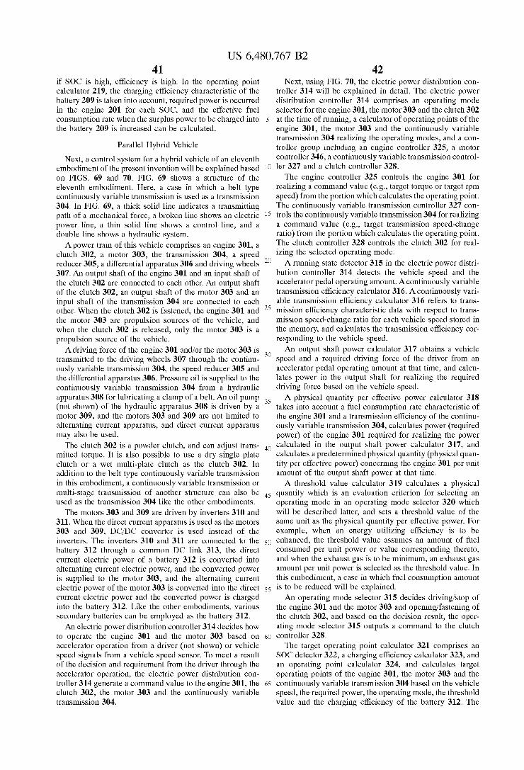
US 6,480,767 B2 41
if SOC is high, efficiency is high. In the operating point calculator 219, the charging efficiency characteristic of the battery 209 is taken into account, required power is occurred in the engine 201 for each SOC, and the effective fuel consumption rate when the Surplus power to be charged into the battery 209 is increased can be calculated.
Parallel Hybrid Vehicle Next, a control system for a hybrid vehicle of an eleventh
embodiment of the present invention will be explained based on FIGS. 69 and 70. FIG. 69 shows a structure of the eleventh embodiment. Here, a case in which a belt type continuously variable transmission is used as a transmission 304. In FIG. 69, a thick solid line indicates a transmitting path of a mechanical force, a broken line shows an electric power line, a thin Solid line shows a control line, and a double line Shows a hydraulic System. A power train of this vehicle comprises an engine 301, a
clutch 302, a motor 303, the transmission 304, a speed reducer 305, a differential apparatus 306 and driving wheels 307. An output shaft of the engine 301 and an input shaft of the clutch 302 are connected to each other. An output shaft of the clutch 302, an output shaft of the motor 303 and an input shaft of the transmission 304 are connected to each other. When the clutch 302 is fastened, the engine 301 and the motor 303 are propulsion sources of the vehicle, and when the clutch 302 is released, only the motor 303 is a propulsion Source of the vehicle. A driving force of the engine 301 and/or the motor 303 is
transmitted to the driving wheels 307 through the continu ously variable transmission 304, the speed reducer 305 and the differential apparatus 306. Pressure oil is supplied to the continuously variable transmission 304 from a hydraulic apparatus 308 for lubricating a clamp of a belt. An oil pump (not shown) of the hydraulic apparatus 308 is driven by a motor 309, and the motors 303 and 309 are not limited to alternating current apparatus, and direct current apparatus may also be used.
The clutch 302 is a powder clutch, and can adjust trans mitted torque. It is also possible to use a dry Single plate clutch or a wet multi-plate clutch as the clutch 302. In addition to the belt type continuously variable transmission in this embodiment, a continuously variable transmission or multi-stage transmission of another Structure can also be used as the transmission 304 like the other embodiments.
The motors 303 and 309 are driven by inverters 310 and 311. When the direct current apparatus is used as the motors 303 and 309, DC/DC converter is used instead of the inverters. The inverters 310 and 311 are connected to the battery 312 through a common DC link 313, the direct current electric power of a battery 312 is converted into alternating current electric power, and the converted power is supplied to the motor 303, and the alternating current electric power of the motor 303 is converted into the direct current electric power and the converted power is charged into the battery 312. Like the other embodiments, various Secondary batteries can be employed as the battery 312. An electric power distribution controller 314 decides how
to operate the engine 301 and the motor 303 based on accelerator operation from a driver (not shown) or vehicle Speed signals from a vehicle Speed Sensor. To meet a result of the decision and requirement from the driver through the accelerator operation, the electric power distribution con troller 314 generate a command value to the engine 301, the clutch 302, the motor 303 and the continuously variable transmission 304.
15
25
35
40
45
50
55
60
65
42 Next, using FIG. 70, the electric power distribution con
troller 314 will be explained in detail. The electric power distribution controller 314 comprises an operating mode selector for the engine 301, the motor 303 and the clutch 302 at the time of running, a calculator of operating points of the engine 301, the motor 303 and the continuously variable transmission 304 realizing the operating modes, and a con troller group including an engine controller 325, a motor controller 346, a continuously variable transmission control ler 327 and a clutch controller 328.
The engine controller 325 controls the engine 301 for realizing a command value (e.g., target torque or target rpm Speed) from the portion which calculates the operating point. The continuously variable transmission controller 327 con trols the continuously variable transmission 304 for realizing a command value (e.g., target transmission Speed-change ratio) from the portion which calculates the operating point. The clutch controller 328 controls the clutch 302 for real izing the Selected operating mode. A running state detector 315 in the electric power distri
bution controller 314 detects the vehicle speed and the accelerator pedal operating amount. A continuously variable transmission efficiency calculator 316. A continuously vari able transmission efficiency calculator 316 refers to trans mission efficiency characteristic data with respect to trans mission Speed-change ratio for each vehicle Speed Stored in the memory, and calculates the transmission efficiency cor responding to the vehicle Speed. An output shaft power calculator 317 obtains a vehicle
Speed and a required driving force of the driver from an accelerator pedal operating amount at that time, and calcu lates power in the output shaft for realizing the required driving force based on the vehicle speed. A physical quantity per effective power calculator 318
takes into account a fuel consumption rate characteristic of the engine 301 and a transmission efficiency of the continu ously variable transmission 304, calculates power (required power) of the engine 301 required for realizing the power calculated in the output shaft power calculator 317, and calculates a predetermined physical quantity (physical quan tity per effective power) concerning the engine 301 per unit amount of the output shaft power at that time. A threshold value calculator 319 calculates a physical
quantity which is an evaluation criterion for Selecting an operating mode in an operating mode Selector 320 which will be described latter, and sets a threshold value of the Same unit as the physical quantity per effective power. For example, when an energy utilizing efficiency is to be enhanced, the threshold value assumes an amount of fuel consumed per unit power or value corresponding thereto, and when the exhaust gas is to be minimum, an exhaust gas amount per unit power is Selected as the threshold value. In this embodiment, a case in which fuel consumption amount is to be reduced will be explained. An operating mode Selector 315 decides driving/stop of
the engine 301 and the motor 303 and opening/fastening of the clutch 302, and based on the decision result, the oper ating mode Selector 315 outputs a command to the clutch controller 328. The target operating point calculator 321 comprises an
SOC detector 322, a charging efficiency calculator 323, and an operating point calculator 324, and calculates target operating points of the engine 301, the motor 303 and the continuously variable transmission 304 based on the vehicle Speed, the required power, the operating mode, the threshold value and the charging efficiency of the battery 312. The
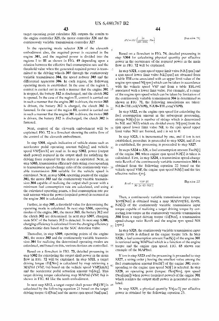
US 6,480,767 B2 43
target operating point calculator 321 outputs the results to the engine controller 325, the motor controller 326 and the continuously variable transmission controller 327.
In the operating mode selector 320 of the eleventh embodiment also, the required power is occurred in the engine 301, and the required power is divided into the regions I to III as shown in FIG. 49 depending upon a relation between the effective fuel consumption rate and the threshold value when the generated required power is trans mitted to the driving wheels 307 through the continuously variable transmission 304, the speed reducer 305 and the differential apparatus 306. In each region, the following operating mode is established. In the case of the region I, control is carried out in Such a manner that the engine 301 is stopped, the battery 312 is discharged, and the clutch 302 is opened. In the case of the region II, control is carried out in such a manner that the engine 301 is driven, the motor 303 is driven, the battery 312 is charged, the clutch 302 is fastened. In the case of the region III, control is carried out in such a manner that the engine 301 is driven, the motor 303 is driven, the battery 312 is discharged, the clutch 302 is fastened.
Next, control of the eleventh embodiment will be explained. FIG.72 is a flowchart showing the entire flow of the control of the eleventh embodiment.
In step S301, signals indicative of vehicle states such as accelerator pedal operating amount 0adeg and vehicle speed VSPkm/h) are read in. In step S302, power (output shaft power) required in the output shaft for satisfying the driving force required by the driver is calculated. Next, in Step S303, transmission efficiency data String corresponding to transmission Speed-change ratio of the continuously vari able transmission 304 Suitable for the vehicle speed is calculated. Next, in Step S304, operating points of the engine 301, the motor 303 and the continuously variable transmis sion 304 capable of realizing the output shaft power with a minimum fuel consumption rate are calculated, and using the calculated operating points, a fuel consumption rate per unit amount when the power (required power) is occurred in the engine 301 is calculated.
Further, in step 305, a threshold value for determining the operating mode is calculated. In next Step S306, operating modes of the engine 301, the motor 303, the battery 312 and the clutch 302 are determined. In next step S307, charging state SOC of the battery 312 is detected. In next step S308, charging efficiency is calculated from the charging efficiency characteristic data based on the SOC detection value.
Thereafter, in step S309, operating points of the engine 301, the motor 303 and the continuously variable transmis Sion 304 for realizing the determined operating modes are calculated, and based on this, various devices are controlled.
Based on a flowchart in FIG. 73, detailed processing in step S302 for calculating the output shaft power in the main flow in FIG. 72 will be explained. In step S311, a target driving torque tTodNm is calculated by map retrieving a MAPttd (VSP, 0a) based on the vehicle speed VSPkm/h) and the accelerator pedal actuation amount 0adeg). This target driving torque calculating map MAPttd (VSP, 0a) is shown in FIG. 61 like the tenth embodiment.
In next step S312, a target output shaft power t?dkW) is calculated by the following equation 21 based on the target driving torque tTcl Nm) and the motor rpm speed Nimrpm).
15
25
35
40
45
50
55
60
65
44
27t 60. 1000
Equation 21 iPd = Ti ( Nm)
Based on a flowchart in FIG. 74, detailed processing in step S304 for calculating physical quantity per effective power in the occurrence of the required power in the main flow in FIG. 72 will be explained.
In step S321, a rpm speed upper limit value Nilurpm and a rpm speed lower limit value NiL rpm are obtained from a table TBLcvtu associated with an upper limit value of the engine rpm speed Nirpm which can be taken in accordance with the vehicle speed VSP and from a table TBLcvtl asSociated with a lower limit value. For example, if a range of the engine rpm Speed which can be taken by limitation of the continuously variable transmission 304 is determined as shown in FIG. 71, the following associations are taken: NiL0=TBLevtl(VSPO), NiU0=TBLevtu(VSP0).
In Step S322, as the engine rpm Speed for calculating the fuel consumption amount in the Subsequent processing, strings NiSn) (n is number of strings which is determined by NiL and NiU) which are divided every 50rpm) from the rpm Speed lower limit value NiL to the rpm Speed upper limit value NiO are formed, and i is set to 0.
In step S323, i is incremented by one, and if i>n is not established, procedure is proceeded to Step S324, and if i>n is established, the processing is proceeded to Step S327.
In steps S324 to 326, a fuel consumption amount FuelSi of the engine 301 when engine rpm speed NiSi is taken is calculated. First, in Step S324, a transmission Speed-change ratio RcvtS of the continuously variable transmission 304 is obtained from the following equation 22 based on the vehicle speed VSP, the engine rpm speed NiSi and the tire effective radius rim).
WSP.10
36.27t. 60. NiSIi RotS = Equation 22
Then, a continuously variable transmission input torque TcvtSNm) is obtained using a map MAPcvt(tTd, RcvtS, NiSil) of the continuously variable transmission input torque capable of realizing a target driving torque by cor recting loSS torque in the continuously variable transmission 304 from a target driving torque tTcl Nm), a transmission Speed-change ratio RcvtS and the engine rpm Speed NiS rpm). In step S325, the continuously variable transmission input
torque TcvtS is defined as the engine torque TeS. In Step S326, a fuel consumption amount FuelSi of the engine 301 is retrieved using MAPfuel which is a function of the engine torque and the engine rpm Speed. FIG. 65 shows one example of the MAPfuel.
If i>n in Step S323 and the processing is proceeded to Step S327, a String order having the Smallest value among the fuel consumption amount FuelS) of the engine 301 corre sponding to the engine rpm speed NiS is selected. In Step S328, an operating point (torque: tTenNm), rpm speed tNenrpm) when power (required power) of the engine 301 which realizes the output shaft power is generated is calcu lated.
In step S329, a physical quantity Vincc/J per effective power is obtained by the following equation 23.
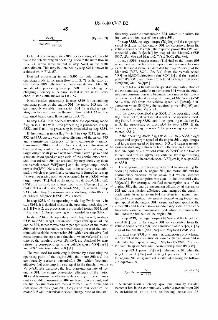
US 6,480,767 B2 45
Fuel Si 27t
60. 1000
Equation 23 W = Equation 23
tTen. iiNen.
Detailed processing in step 305 for calculating a threshold value for determining an operating mode in the main flow in FIG. 72 is the same as that in step S204 in the tenth embodiment. This may be obtained by step S204' shown in a flowchart in FIG. 57.
Detailed processing in step S306 for determining an operating mode in the main flow in FIG. 72 is the same as that in step S205 in the tenth embodiment shown in FIG. 58, and detailed processing in step S308 for calculating the charging efficiency is the Same as that shown in the flow chart in step S204 shown in FIG. 59.
Next, detailed processing in step S309 for calculating operating points of the engine 301, the motor 303 and the continuously variable transmission 304 for realizing oper ating modes determined in the main flow in FIG.72 will be explained based on a flowchart in FIG. 75.
In step S331, it is decided whether the operating mode flag Fw is 1. If Fw is 1, the processing is proceeded to Step S332, and if not, the processing is proceeded to step S334.
If the operating mode flag Fw is 1 in step S331, in steps 332 and 333, energy conversion efficiency of the motor 303 and transmission efficiency of the continuously variable transmission 304 are taken into account, a combination of the operating point of the motor 303 capable of realizing the target output shaft power with minimum electric power and a transmission Speed-change ratio of the continuously vari able transmission 304 are obtained by map retrieving from the vehicle speed VSPkm/h) and the target output shaft power t?nkW). Here, as the map to be retrieved, a combi nation which was previously calculated is formed as a map for every operating point to be obtained. In step S332, when target torque tTmINm of the motor is calculated, Mapttm1 (VSP, tRn) is used, and a target rpm speed tNm rpm) of the motor 303 is calculated, Maptnm1(VSP, tRn) is used. In step S333, when target transmission Speed-change ratio tRcvt is calculated, Maptrevt1(VSP, tRn) is used.
In step S331, if the operating mode flag Fw is not 1, in step S334, it is decided whether the operating mode flag Fw is 2. If Fw is 2, the processing is proceeded to step S334, and if Fw is not 2, the processing is proceeded to step S338.
In step S334, if the operating mode flag Fw is 2, in steps S335 to S337, target torque and target rpm speed of the engine 301, target torque and target rpm Speed of the motor 303 and target transmission Speed-change ratio of the con tinuously variable transmission 304 which are effective fuel consumption rate equal to a threshold value Vccc/kJ at the time of the required power tRnkW), are obtained by map retrieving corresponding to the vehicle speed VSPkm/h) and SOC detection value SOC%). The map used for retrieving is formed by associating the
operating point of the engine 301, the motor 303 and the continuously variable transmission 304 which becomes effective fuel consumption rate equal to the threshold value Vccc/kJ). For example, the fuel consumption rate of the engine 301, the energy conversion efficiency of the motor 303 and transmission efficiency data string of the continu ously variable transmission 304 are taken into account, and the fuel consumption rate map is formed using torque and rpm Speed of the engine 301, torque and rpm Speed of the motor 303 and transmission Speed-change ratio of the con
15
25
35
40
45
50
55
60
65
46 tinuously variable transmission 304 which minimizes the fuel consumption rate of the engine 301.
In step S335, the target torque tTeNm) and the target rpm speed tNerpm of the engine 301 are calculated from the vehicle speed VSPkm/h), the required power t?nkW) and threshold value Vc.cc/kJ by map of the Maptte2 (VSP, SOC, tRn, Vc) and Maptne2 (VSP, SOC, tFn, Vc).
In step S336, a target torque tTmINm of the motor 303 when the effective fuel consumption rate becomes the same as the threshold value is calculated by map retrieving of the Mapttm2 (VSP, SOC, tRn, Vc) from the vehicle speed VSPkm/h)SOC detection value SOC% and the required power t?nkW), and these are defined as target rpm speed tNimrpm and tNerpm.
In step S337, a transmission speed-change ratio tRcvt of the continuously variable transmission 304 when the effec tive fuel consumption rate becomes the same as the thresh old value is calculated by map retrieving of Maptrevt2 (VSP, SOC, tpn, Vc) from the vehicle speed VSPkm/h), SOC detection value SOC%), the required power t?nkW and the threshold value Vccc/kJ).
In the above-described step S334, if the operating mode flag Fw is not 2, it is decided whether the operating mode flag Fw is 3 in step S338, and if the operating mode flag Fw is 3, the processing is proceeded to step S339. If the operating mode flag Fw is not 3, the processing is proceeded to step S3312.
If the operating mode flag Fw is 3 in step S338, target torque and target rpm Speed of the engine 301, target torque and target rpm Speed of the motor 303 and target transmis Sion Speed-change ratio which are effective fuel consump tion rate equal to a threshold value Vccc/kJ at the time of the required power t?nkW), are obtained by map retrieving corresponding to the vehicle speed VSPkm/h) in steps S339 to S3311. The map used for retrieving is formed by associating the
operating points of the engine 301, the motor 303 and the continuously variable transmission 304 which becomes effective fuel consumption rate equal to the threshold value Vccc/kJ). For example, the fuel consumption rate of the engine 301, the energy conversion efficiency of the motor 303 and transmission efficiency data string of the continu ously variable transmission 304 are taken into account, and the fuel consumption rate map is formed using torque and rpm Speed of the engine 301, torque and rpm Speed of the motor 303 and transmission Speed-change ratio of the con tinuously variable transmission 304 which minimizes the fuel consumption rate of the engine 301.
In step S339, the target torque tTeNm) and the target rpm speed tNerpm of the engine 301 are calculated from the vehicle speed VSPkm/h) and threshold value Vccc/kJ by map of the Maptte3 (VSP, Vc) and Maptnes (VSP, Vc).
In next step S3310, a target transmission Speed-change ratio tRcvt of the continuously variable transmission 304 is calculated by map retrieving of MaptrevT3(VSP, tRn) from the vehicle speed VSP and the required power t?nkW).
In step S3311, power tRgkW of the engine 301 when the target torque tTeNm) and the target rpm speed tNerpm of the engine 301 are generated is calculated using the follow ing equation 24.
27t 60. 1000
Equation 24 tFg = t Te. twe.
A transmission efficiency mcvt continuously variable transmission in the continuously variable transmission 304 is calculated using the following equation 25.
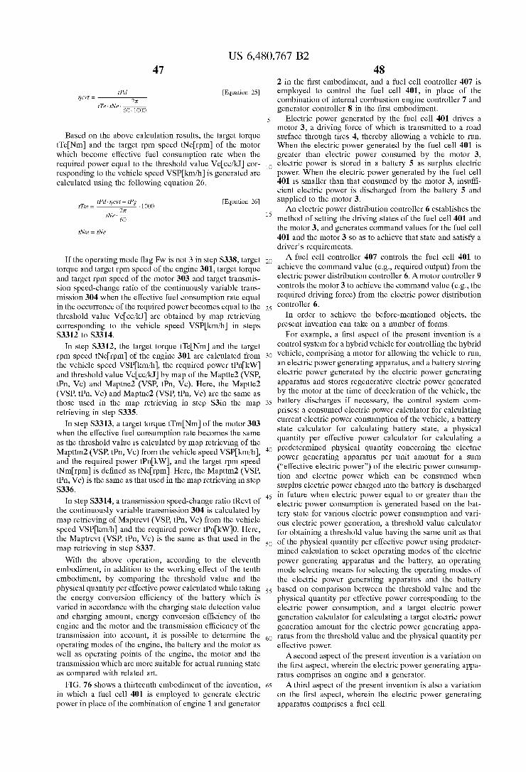
US 6,480,767 B2 47
tP 27t
60. 1000
Equation 25 incvt =
tTe. iNe.
Based on the above calculation results, the target torque tTeNm) and the target rpm speed tNerpm of the motor which become effective fuel consumption rate when the required power equal to the threshold value Vccc/kJ cor responding to the vehicle speed VSPkm/h) is generated are calculated using the following equation 26.
tramcvt - trg Equation 26 tT = Equation 26 ... 1000
tNet iWin = iNe
If the operating mode flag Fw is not 3 in step S338, target torque and target rpm Speed of the engine 301, target torque and target rpm Speed of the motor 303 and target transmis Sion Speed-change ratio of the continuously variable trans mission 304 when the effective fuel consumption rate equal in the occurrence of the required power becomes equal to the threshold value Vccc/kJ) are obtained by map retrieving corresponding to the vehicle speed VSPkm/h) in steps S3312 to S3314.
In step S3312, the target torque tTeNm) and the target rpm speed tNerpm of the engine 301 are calculated from the vehicle speed VSPkm/h), the required power tRnkW) and threshold value Vc.cc/kJ by map of the Maptte2 (VSP, tPn, Vc) and Maptne2 (VSP, tRn, Vc). Here, the Maptte2 (VSP, tBn, Vc) and Maptne2 (VSP, tBn, Vc) are the same as those used in the map retrieving in Step S3in the map retrieving in step S335.
In step S3313, a target torque tTmINm of the motor 303 when the effective fuel consumption rate becomes the same as the threshold value is calculated by map retrieving of the Mapttm2 (VSP, tRn, Vc) from the vehicle speed VSPkm/h), and the required power t?nkW), and the target rpm speed tNm rpm) is defined as tNerpm). Here, the Mapttm2 (VSP, tPn, Vc) is the same as that used in the map retrieving in Step S336.
In step S3314, a transmission speed-change ratio tRcvt of the continuously variable transmission 304 is calculated by map retrieving of Maptrevt (VSP, tRn, Vc) from the vehicle speed VSPkm/h) and the required power t?nkW10. Here, the Maptrevt (VSP, tFn, Vc) is the same as that used in the map retrieving in step S337. With the above operation, according to the eleventh
embodiment, in addition to the working effect of the tenth embodiment, by comparing the threshold value and the physical quantity per effective power calculated while taking the energy conversion efficiency of the battery which is varied in accordance with the charging State detection value and charging amount, energy conversion efficiency of the engine and the motor and the transmission efficiency of the transmission into account, it is possible to determine the operating modes of the engine, the battery and the motor as well as operating points of the engine, the motor and the transmission which are more Suitable for actual running State as compared with related art.
FIG. 76 shows a thirteenth embodiment of the invention, in which a fuel cell 401 is employed to generate electric power in place of the combination of engine 1 and generator
15
25
35
40
45
50
55
60
65
48 2 in the first embodiment, and a fuel cell controller 407 is employed to control the fuel cell 401, in place of the combination of internal combustion engine controller 7 and generator controller 8 in the first embodiment.
Electric power generated by the fuel cell 401 drives a motor 3, a driving force of which is transmitted to a road Surface through tires 4, thereby allowing a vehicle to run. When the electric power generated by the fuel cell 401 is greater than electric power consumed by the motor 3, electric power is Stored in a battery 5 as Surplus electric power. When the electric power generated by the fuel cell 401 is smaller than that consumed by the motor 3, insuffi cient electric power is discharged from the battery 5 and supplied to the motor 3. An electric power distribution controller 6 establishes the
method of setting the driving states of the fuel cell 401 and the motor 3, and generates command values for the fuel cell 401 and the motor 3 so as to achieve that state and satisfy a driver's requirements. A fuel cell controller 407 controls the fuel cell 401 to
achieve the command value (e.g., required output) from the electric power distribution controller 6. A motor controller 9 controls the motor 3 to achieve the command value (e.g., the required driving force) from the electric power distribution controller 6.
In order to achieve the before-mentioned objects, the present invention can take on a number of forms.
For example, a first aspect of the present invention is a control system for a hybrid vehicle for controlling the hybrid vehicle, comprising a motor for allowing the vehicle to run, an electric power generating apparatus, and a battery Storing electric power generated by the electric power generating apparatus and stores regenerative electric power generated by the motor at the time of deceleration of the vehicle, the battery discharges if necessary, the control System com prises: a consumed electric power calculator for calculating current electric power consumption of the vehicle, a battery State calculator for calculating battery State, a physical quantity per effective power calculator for calculating a predetermined physical quantity concerning the electric power generating apparatus per unit amount for a Sum (“effective electric power”) of the electric power consump tion and electric power which can be consumed when Surplus electric power charged into the battery is discharged in future when electric power equal to or greater than the electric power consumption is generated based on the bat tery State for various electric power consumption and Vari ous electric power generation, a threshold value calculator for obtaining a threshold value having the Same unit as that of the physical quantity per effective power using predeter mined calculation to Select operating modes of the electric power generating apparatus and the battery, an operating mode Selecting means for Selecting the operating modes of the electric power generating apparatus and the battery based on comparison between the threshold value and the physical quantity per effective power corresponding to the electric power consumption, and a target electric power generation calculator for calculating a target electric power generation amount for the electric power generating appa ratus from the threshold value and the physical quantity per effective power. A Second aspect of the present invention is a variation on
the first aspect, wherein the electric power generating appa ratus comprises an engine and a generator. A third aspect of the present invention is also a variation
on the first aspect, wherein the electric power generating apparatus comprises a fuel cell.

US 6,480,767 B2 49
According to the first to third aspects of the present invention, the current electric power consumed by running and by auxiliary equipment, and the battery State calculator calculates the energy conversion efficiency during charging and discharging of the battery and the corresponding battery State. Based on this battery State, A fourth aspect of the present invention is a variation on
any of the first to the third aspects, wherein the physical quantity per effective power is a fuel consumption amount per effective electric power of the engine or the fuel cell.
According to the fourth aspect of the present invention, the amount of fuel consumed per effective electric power by the engine or the fuel cell is used as the physical quantity per effective power, thereby enabling a reduction in the amount of fuel consumed with respect to the electric energy. A fifth aspect of the present invention is a control System
for a hybrid vehicle according to any one of the first to third aspects, wherein the physical quantity per effective power is an exhaust gas amount per effective electric power of the engine or the fuel cell.
According to the fifth aspect of the present invention, the amount of exhaust gas per effective electric power by the engine or the fuel cell is used as the physical quantity per effective power, thereby enabling a reduction in the amount of exhaust gas with respect to the electric energy. A Sixth aspect of the present invention is variation on a
control System for a hybrid vehicle according to any one of the first to fifth aspects, wherein the operating mode Select ing means Selects (1) a first operating mode for Supplying electric power which is equal to the electric power con Sumption from the battery when the electric power con Sumption is Smaller than electric power which can be generated at maximum electric power generating efficiency point of the electric power generating apparatus, and the physical quantity per effective power rate corresponding to the electric power consumption is not preferable as com pared with the threshold value, (2) a Second operating mode, in which electric power electric power which becomes the physical quantity per effective power rate equal to the threshold value is generated by the electric power generating apparatus and Surplus electric power with respect to the electric power consumption is Stored in the battery when the physical quantity per effective power rate corresponding to the electric power consumption, is more preferable than the threshold value, (3) a third operating mode, in which maxi mum electric power which is equal to or less than the threshold value is generated by the electric power generating apparatus and insufficient electric power with respect to the electric power consumption is Supplied from the battery when the electric power consumption is equal to or greater than electric power which can be generated at maximum electric power generating efficiency point of the electric power generating apparatus and the physical quantity per effective power rate corresponding to the electric power consumption, is less preferable than the threshold value, and (4) a fourth operating mode, in which the electric power generating apparatus generates electric power which is equal to the electric power consumption when the physical quan tity per effective power rate corresponding to the electric power consumption and the threshold value coincide each other.
According to the Sixth aspect of the present invention, in a case in which the consumed electric power is Smaller than the electric power generatable at the maximum generating efficiency of the electrical power generating apparatus and further in which the physical quantity per effective electric
15
25
35
40
45
50
55
60
65
SO power corresponding to the electric power is leSS preferable than the threshold value, a first operating mode is Selected, in which an electric power of the same amount as the consumed electric power is Supplied to the battery, a case in which the physical quantity per effective electric power corresponding to the consumed electric power is less favor able than the threshold value, the Second operating mode is Selected, in which the electrical power generating apparatus generates an amount of electric power that is the physical quantity per effective electric power equal to the threshold value, and in which Surplus electric power beyond the consumed electric power is Stored in the battery, in a case in which the consumed electric power is greater than the amount of electric power generatable at the maximum electric generating point of the electrical power generating apparatus and further in which the physical quantity per effective electric power corresponding to the consumed electric power is less favorable than the threshold value, a third operating mode is Selected, in which maximum electric power, which is equal to or less than the threshold value is generated by the electrical power generating apparatus and in which insufficient electric power with respect to the consumed electric power is Supplied from the battery, and in a case in which the physical quantity per effective electric power corresponding to the consumed electric power coin cides with the threshold value, a fourth operating mode is Selected, in which the electrical power generating apparatus generates an amount of electric power that is the same as the consumed electric power. The result of the above-described mode Selections is the achievement of a high overall System fuel economy. A Seventh aspect of the present invention is a variation on
a control System for a hybrid vehicle according to the Sixth aspect, wherein the target electric power generation calcu lator (1) sets the target electric power generation to 0 when the first operating mode is Selected by the operating mode Selecting means, (2) retrieves the generated electric power which becomes the physical quantity per effective power rate which is equal to the threshold value in the physical quantity per effective power rate calculator, and the retrieved value is defined as the target generated electric power when the Second operating mode is Selected by the operating mode Selecting means, (3) retrieves maximum electric power which becomes the physical quantity per effective power rate which is smaller than the threshold value in the physical quantity per effective power rate calculator, and the retrieved value is defined as the target generated electric power when the third operating mode is Selected by the operating mode Selecting means, and (4) defines electric power which is equal to the electric power consumption as the target gen erated electric power when the fourth operating mode is Selected by the operating mode Selecting means.
According to the Seventh aspect of the present invention, the effect of the above-noted actions (1) to (4) is that the target electric power is generated with an improved overall System fuel economy. An eight aspect of the present invention is a variation on
a control System for a hybrid vehicle according to any one of the first to seventh aspects, wherein the threshold value calculator calculates a threshold value concerning a physical quantity which is Subject in association with a battery State, the association relation is a relation in which a physical quantity at the time of electric power generation becomes more excellent as the battery State approaches a condition of utilizable range of the battery, and in which electric power is generated even if the physical quantity is not as good as the battery State approaches a lower limit of the utilizable range of the battery.
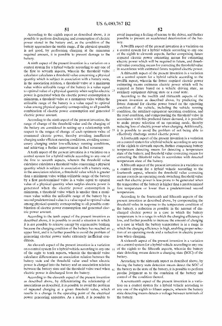
US 6,480,767 B2 S1
According to the eighth aspect as described above, it is possible to perform discharging and consumption of electric power Stored in the battery and, as the condition of the battery approaches the uSable range, if the physical quantity is not good, by performing charging at the minimum required amount, it is possible to prevent damage to the battery. A ninth aspect of the present invention is a variation on a
control System for a hybrid vehicle according to any one of the first to seventh aspects, wherein the threshold value calculator calculates a threshold value concerning a physical quantity which is Subject in association with a battery State, in the association relation, a threshold value at a minimum value within utilizable range of the battery is a value equal to optimal value of a physical quantity when Surplus electric power is generated when the electric power consumption is minimum, a threshold value at a maximum value within the utilizable range of the battery is a value equal to optimal value among physical quantity corresponding to all possible combination of electric power consumption and generated electric power amount.
According to the ninth aspect of the present invention, the range of change of the threshold value and the charging of the battery are considered in Setting up a relationship with respect to the ranges of change of each optimum value of consumed electric power, thereby avoiding insufficient charging under efficient running conditions, avoiding unnec essary charging under low-efficiency running conditions, and achieving a further improvement in fuel economy. A tenth aspect of the present invention is a variation on a
control System for a hybrid vehicle according to any one of the first to seventh aspects, wherein the threshold value calculator calculates a threshold value concerning a physical quantity which is Subject in association with a battery State, in the association relation, a threshold value which is greater than a minimum value within utilizable range of the battery by a first predetermined value is a value equal to optimal value of a physical quantity when Surplus electric power is generated when the electric power consumption is minimum, a threshold value which is Smaller than a maxi mum value within the utilizable range of the battery by a Second predetermined value is a value equal to optimal value among physical quantity corresponding to all possible com bination of electric power consumption and generated elec tric power amount.
According to the tenth aspect of the present invention as described above, it is possible to avoid a Situation in which it is not possible to retrieve energy by regenerative braking because the charging condition of the battery has reached an upper limit, and it is further possible to avoid the problem of generating electric power under eXtremely inefficient con ditions.
An eleventh aspect of the present invention is a variation on a control System for a hybrid vehicle according to any one of the eight to tenth aspects, wherein the threshold value calculator differentiates an association relation between the battery state and the threshold value used when electric power is charged into the battery and an association relation between the battery state and the threshold value used when electric power is discharged from the battery.
According to the eleventh aspect of the present invention as described above, by differentiating the relationship of asSociations as described, it is possible to avoid the problem of repeated charging at a given threshold value, which results in a change in the operating point of the electrical power generating apparatus. AS a result, it is possible to
15
25
35
40
45
50
55
60
65
52 avoid imparting a feeling of unease to the driver, and further possible to prevent an accelerated deterioration of the bat tery. A twelfth aspect of the present invention is a variation on
a control System for a hybrid vehicle according to any one of the eighth to eleventh aspects, further comprising future required electric power estimating means for estimating electric power which will be required in future, and thresh old value correcting means for correcting the threshold value in accordance with estimated future required electric power. A thirteenth aspect of the present invention is a variation
on a control System for a hybrid vehicle according to the twelfth aspect, wherein the future required electric power estimating means estimates electric power which will be required in future based on a vehicle driving State, an auxiliary equipment driving State or a road State. According to the twelfth and thirteenth aspects of the
present invention as described above, by predicting the future demand for electric power based on the operating condition of the vehicle, including the vehicle running condition, the auxiliary equipment operating condition, and the road condition, and compensating the threshold value in accordance with this predicted future demand, it is possible to make proper Selection of an operating mode, thereby reducing loSS of electric power when charging. Additionally, it is possible to avoid the problem of not being able to effectively discharge Stored electric power. A fourteenth aspect of the present invention is a variation
on a control System for a hybrid vehicle according to any one of the eighth to eleventh aspects, further comprising battery temperature detecting means for detecting a temperature State of the battery, and threshold value correcting means for correcting the threshold value in accordance with detected temperature State of the battery. A fifteenth aspect of the present invention is a variation on
a control System for a hybrid vehicle according to the fourteenth aspect, wherein the threshold value correcting means corrects an operating mode Switching threshold value Such that electric power is leSS prone to be generated when the temperature of the battery is higher than a predetermined first temperature or lower than a predetermined Second temperature.
According to the fourteenth and fifteenth aspects of the present invention as described above, by compensating the threshold value in response to the temperature condition of the battery, a reduction is possible in the amount of dis charged electric power in a case in which the battery temperature is in a range in which the charging efficiency is low, and further possible to increase the amount of charging in a case in which the battery temperature is in a range in which the charging efficiency is high, enabling proper Selec tion of an operating mode and a reduction in electric power loSS when charging. A sixteenth aspect of the present invention is a variation
on a control System for a hybrid vehicle according to any one of the eighth to the fifteenth aspects, wherein the battery State detecting means detects a charging State (SOC) of the battery.
According to the Sixteenth aspect as described above, by having the battery state detection means detect the SOC of the battery as the state of the battery, it is possible to perform precise judgment as to the condition of the battery and control of the condition thereof. A Seventeenth aspect of the present invention is a varia
tion on a control System for a hybrid vehicle according to any one of the eighth to fifteen aspects, wherein the battery State detecting means detects a Voltage between terminals of the battery.

US 6,480,767 B2 S3
According to the Seventeenth aspect as described above, by having the battery State detection means detect the terminal-to-terminal Voltage of the battery as the battery condition, it is possible to judge and control the battery condition using a simple configuration. An eighteenth aspect of the present invention is a varia
tion on a control System for a hybrid vehicle according to any one of the eight to the fifteenth aspects, wherein the battery State detecting means detects an internal resistance of the battery.
According to the eighteenth aspect as described above, by having the battery State detection means detect the internal resistance of the battery as the battery condition, it is possible to judge and control the battery condition using a Simple configuration. A nineteenth aspect of the present invention is a variation
on a control System for a hybrid vehicle comprising an engine, a motor, a battery and a transmission, in which power of at least one of the engine and the motor is transmitted to an output shaft through the transmission, the control System comprising means for detecting a vehicle Speed, means for detecting an accelerator pedal actuation amount, an output shaft power calculator for calculating power ("output shaft power', hereinafter) in an output shaft based on the vehicle Speed detection value and the accel erator pedal depressing amount detection value, a battery State calculator for calculating energy efficiency or a battery State corresponding thereto at the time of charging and discharging of the battery, a transmission transmitting effi ciency calculator for calculating the transmitting efficiency from transmitting efficiency characteristic with respect to transmission Speed-change ratio, physical quantity per effec tive power in the occurrence of the required power calcu lator in which fuel consumption rate characteristic of the engine and transmitting efficiency of the transmission are taken into account, and when power required for realizing the output shaft power (“required power, hereinafter) is generated in the engine, a predetermined physical quantity concerning the engine per unit amount of the output shaft power ("physical quantity per effective power in the occur rence of the required power, hereinafter) is calculated, a threshold value for Setting a threshold value having the same unit as that of the physical quantity per effective power in the occurrence of the required power for Selecting operating modes for the engine and the motor, means for determining a State, which determines whether or not the physical quantity per effective power in the occurrence of the required power is in a preferable State with respect to the threshold value, means for comparing the required power and power (“minimum fuel consumption power', hereinafter) at an operating point of the engine in which a predetermined physical quantity concerning the engine per unit power with each other in size, an operating mode Selecting means for Selecting operating modes for the engine and the motor based on the State decision result and the power comparison result, a physical quantity calculator for calculating a predetermined physical quantity ("physical quantity per effective power rate”, hereinafter) concerning the engine per unit amount of a Sum of the output shaft power when power which is equal to or greater than the required power is occurred in the engine and power used for generating electric power which can be utilized when power charged in the battery from Surplus power with respect to various required power and various power of the engine, and a target unit operating point calculator for calculating, based on the operating mode, (1) torque and rpm speed of the motor and transmission Speed-change ratio of the transmis
15
25
35
40
45
50
55
60
65
S4 Sion for realizing the output shaft power while taking transmitting efficiency of the transmission when the vehicle runs by the motor, and (2) power of the engine which becomes physical quantity per effective power rate equal to the threshold value based on the physical quantity per effective power rate calculator, and torque and rpm Speed of the engine, torque and rpm Speed of the motor and trans mission Speed-change ratio of the transmission which Satisfy both the output shaft power and power of the engine when the vehicle runs by the engine, or the engine and the motor.
According to the nineteenth aspect as described above, by performing a comparison between a threshold value and a prescribed physical quantity of the engine per effective power rate with respect to the Sum of a power rate at the output Shaft calculated by considering the energy conversion efficiency of the engine, the motor, and the auxiliary equip ment and the power rate of the engine used in generating electric power consumable by first charging the battery with generated electric power, considering the energy conversion efficiency of the engine, the motor, and the auxiliary equip ment and then discharging, and determining the operating mode of the engine and motor during running and the operating points of the engine, the motor, and the transmission, it is possible to achieve a favorable prescribed physical quantity with regard to the engine, in comparison with the related art.
A twentieth aspect of the present invention is a variation on a control System for a hybrid vehicle according to the nineteenth aspect, wherein the physical quantity per effec tive power rate is a fuel consumption amount per effective power in the engine.
According to the twentieth aspect as described above, by using the amount of fuel consumed per power with regard to the engine as the physical quantity per effective power rate, it is possible to achieve a reduction in the amount of fuel consumed, in comparison with the past. A twenty-first aspect of the present invention is a variation
on a control System for a hybrid vehicle according to the nineteenth aspect, wherein the physical quantity per effec tive power rate is an exhaust gas amount per effective electric power of the engine.
According to the twenty-first aspect as described above, by using an exhaust gas component that is to be limited per power rate in the engine as the physical quantity per power rate, it is possible to reduce the exhaust gas component in comparison with the past. A twenty-Second aspect of the present invention is a
variation on a control System for a hybrid vehicle according to any one of the nineteenth to the twenty-first aspects, wherein the operating mode Selecting means Selects (1) a first operating mode for generating power in the motor which satisfies the output shaft power when it is decided in the State decision means that the physical quantity per effective power in the occurrence of the required power is less preferable than the threshold value and when it is decided in the power comparing means that the required power is Smaller than the minimum fuel consumption power, (2) a Second operating mode for generating power which is equal to or greater than the required power in the engine, thereby generating electric power by Surplus power to charge the battery, when it is decided in the State decision means that the physical quantity per effective power in the occurrence of the required power is more preferable than the threshold value, (3) a third operating mode for generating, in the engine, the maximum required power which is equal to or lower than the threshold value when it is decided in the
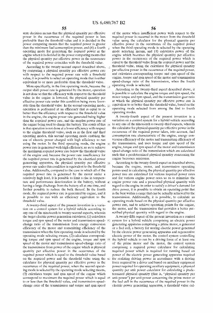
US 6,480,767 B2 SS
State decision means that the physical quantity per effective power in the occurrence of the required power is leSS preferable than the threshold value and it is decided in the power comparing means that the required power is greater than the minimum fuel consumption power, and (4) a fourth operating mode for generating the required power in the engine when it is decided in the power comparing means that the physical quantity per effective power in the occurrence of the required power coincides with the threshold value.
According to the twenty-Second aspect described above, by comparing a physical quantity per effective power rate with respect to the required power rate with a threshold value, it is possible to Select an operating mode that is either equivalent to or more preferable than the threshold value. More Specifically, in the first operating mode, because the
output shaft power rate is generated by the motor, operation is not done so that the efficiency with respect to the threshold value in the engine is lowered, the physical quantity per effective power rate under this condition being more favor able than the threshold value. In the Second operating mode, operation is performed at an efficiency that is equal to or better than the efficiency with respect to the threshold value in the engine, the engine power rate generated being higher than the required power rate, and the Surplus power rate of the engine being used to charge the battery. The result of this is that operation is not done at a lower efficiency with respect to the engine threshold value, Such as in the first and third operating modes, this Second operating mode enabling the use of electric power charged with high efficiency to run using the motor. In the third operating mode, the engine power rate is generated with high efficiency, So as to achieve the maximum required power rate below the threshold value of the engine and, because the power rate insufficiency for the required power rate is generated by the electrical power generating apparatus, the physical quantity per effective power rate under this condition is equivalent to the threshold value. Additionally, compared to the case in which all of the required power rate is generated by the motor under a relatively high load, it is possible to limit a rise in tempera ture and performance deterioration in the battery, without having a large discharge from the battery all at one time, and further possible to reduce the bulk thereof. In the fourth mode, the required power rate is generated by engine, and it is possible to run with an efficiency equivalent to the threshold value. A twenty-third aspect of the present invention is a varia
tion on a control System for a hybrid vehicle according to any one of the nineteenth to twenty-Second aspects, wherein the target electric power generation calculator; (1) calculates torque and rpm Speed of the motor and transmission Speed change ratio of the transmission from energy conversion efficiency of the motor and transmitting efficiency of the transmission when the first operating mode is Selected by the operating mode Selecting means, (2) calculates correspond ing torque and rpm Speed of the engine, torque and rpm Speed of the motor and transmission speed-change ratio of the transmission from power of the engine which is physical quantity per effective power in the occurrence of the required power which is equal to the threshold value based on the required power and the threshold value using the calculator for physical quantity per effective power in the occurrence of the required power, when the Second operat ing mode is Selected by the operating mode Selecting means, (3) calculates torque and rpm speed of the engine which correspond to maximum the required power which is equal to or less than the threshold value, and transmission Speed change ratio of the transmission and torque and rpm Speed
15
25
35
40
45
50
55
60
65
S6 of the motor when insufficient power with respect to the required power is occurred in the motor from the threshold value using the calculator for the physical quantity per effective power in the occurrence of the required power when the third operating mode is Selected by the operating mode Selecting means, and (4) calculates power of the engine which becomes the physical quantity per effective power in the occurrence of the required power which is equal to the threshold value from the required power and the threshold value, using the calculator for physical quantity per effective power in the occurrence of the required power, and calculates corresponding torque and rpm Speed of the engine, torque and rpm Speed of the motor and transmission Speed-change ratio of the transmission, when the fourth operating mode is Selected.
According to the twenty-third aspect described above, it is possible to calculate the engine torque and rpm Speed, the motor torque and rpm Speed, and the transmission gear ratio at which the physical quantity per effective power rate is equivalent to or better than the threshold value, based on the operating mode Selected from among the first to fourth operating modes. A twenty-fourth aspect of the present invention is a
variation on a control System for a hybrid vehicle according to any one of the nineteenth to twenty-third aspects, wherein the calculator for physical quantity per effective power in the occurrence of the required power takes, into account, fuel consumption rate characteristic of the engine, energy con version efficiency of the motor and transmitting efficiency of the transmission, and uses torque and rpm Speed of the engine, torque and rpm Speed of the motor and transmission Speed-change ratio of the transmission which are calculated Such that a predetermined physical quantity concerning the engine becomes minimum.
According to the twenty-fourth aspect as described above, because the engine, motor, and transmission operating points used in calculating the physical quantity per effective power rate are calculated for various required power rates and for various engine power rates So as to minimize the engine power rate and a prescribed physical quantity with regard to the engine in order to Satisfy a driver's demand for drive power, it is possible to obtain an operating point that is the best within a range that can be actually achieved by the transmission. Additionally, it is possible, to calculate an operating mode based on the physical quantity per effective power rate, and to achieve operating points for the engine, the motor, and the transmission that provides a better pre Scribed physical quantity with regard to the engine. A twenty-fifth aspect of the present invention is a control
System for a hybrid vehicle comprising an electric power generating apparatus comprising a prime motor, a generator or a fuel cell, a battery for Storing electric power generated by the electric power generating apparatus and regenerative electric power of the motor, the control System controlling the hybrid vehicle to run by a driving force of at least one of the prime motor and the motor, the control System comprising a required power calculator for calculating required power which is required for running based on power of the electric power generating apparatus required for realizing driving power in accordance with a driving force required by a driver and based on auxiliary equipment power required for operating auxiliary equipment, a physical quantity per unit power calculator for calculating a prede termined physical quantity (that is, "physical quantity per unit power”) per unit power concerning the prime motor or the fuel cell in the occurrence of the required power in the electric power generating apparatus, a threshold value cal

US 6,480,767 B2 57
culator for calculating a threshold value having the same unit as that of the physical quantity per effective power rate which becomes a comparison criterion value for Selecting operating modes for the electric power generating apparatus, the battery and the motor, an operating mode Selecting means for comparing the threshold value and the physical quantity per unit power to Select operating modes of the electric power generating apparatus, the battery and the motor in accordance with a result of the comparison, and an operating point calculator for calculating an operating point of the electric power generating apparatus which becomes equal to or less than the threshold value, wherein the operating point calculator comprises means for detecting a charging State of the battery, a charging efficiency calculator for calculating charging efficiency corresponding to charg ing State and charging amount of the battery based on charging State detection value by the charging State detecting means, and a physical quantity per effective power rate calculator for calculating a predetermined physical quantity (“physical quantity per effective power rate”, hereinafter) concerning the electric power generating apparatus per unit power of a sum (“effective power”, hereinafter) of the driving power and auxiliary equipment power when power which is equal to or greater than the required power is occurred in the electric power generating apparatus, and power charged into the battery using Surplus power for each charging State concerning various the required power, Vari ous power of the prime motor or the fuel cell based on energy conversion efficiency and charging efficiency of the electric power generating apparatus.
According to the twenty-fifth aspect as described above, in a hybrid vehicle having an electrical power generating apparatus formed by a prime motor, a generator, or a fuel cell, a battery for Storing electric power generated by the electrical power generating apparatus and regenerative elec tric power of the motor occurring when the vehicle is decelerating, and a running motor, in which the hybrid vehicle is run by at least one of the prime motor and the motor, by performing a comparison with respect to a thresh old value of a physical quantity per effective power rate calculated considering the battery energy conversion efficiency, which varies in response to the detected charging State and the amount of charging, and the battery and motor energy conversion efficiencies, it is possible to establish operating modes and operating points for the electrical power generating apparatus, the battery, and the motor more favorably than in the past, in response to actual running conditions. A twenty-sixth aspect of the present invention is a control
system for a hybrid vehicle for controlling the hybrid vehicle comprising an engine, a motor for allowing the vehicle to run, a battery for Storing electric power and regenerative electric power generated by the motor, and transmission, in which power of at least one of the engine and the motor is transmitted to an output shaft through the transmission, the control System comprising a required power calculator for calculating required power required for allowing the vehicle to run, based on power of the engine required for realizing driving power in accordance with driving force required by a driver and based on auxiliary equipment power required for operating auxiliary equipment, a physical quantity per effective power rate calculator for calculating a predeter mined physical quantity ("physical quantity per effective power rate', hereinafter) per unit power concerning the engine in the occurrence of the required power in the engine, a threshold value calculator for calculating a threshold value having the same unit as that of the physical quantity per
15
25
35
40
45
50
55
60
65
58 effective power rate which becomes a comparison criterion value for Selecting operating modes of the engine, the battery and the motor, and an operating point calculator for calculating an operating point of the engine which is equal to or less than the threshold value, wherein the operating point calculator comprises a means for detecting a charging State of the battery, a charging efficiency calculator for calculating charging efficiency corresponding to charging State and charging amount of the battery based on charging State detection value by the charging State detecting means, a charging efficiency calculator for calculating charging efficiency corresponding to charging State and charging amount of the battery based on charging State detection value by the charging State detecting means, and a physical quantity per effective power rate calculator for calculating a predetermined physical quantity ("physical quantity per effective power rate”, hereinafter) concerning the electric power generating apparatus per unit power of a Sum (“effective power”, hereinafter) of the driving power and auxiliary equipment power when power which is equal to or greater than the required power is occurred in the electric power generating apparatus, and power charged into the battery using Surplus power for each charging State concern ing various the required power, various power of the prime motor or the fuel cell based on energy conversion efficiency and charging efficiency of the electric power generating apparatuS. According to the twenty-sixth aspect as described above,
in a hybrid vehicle having an engine, electrical power generating apparatus, a running motor, a battery for Storing electric power generated by the electrical power generating apparatus and regenerative electric power of the motor occurring when the vehicle is decelerating, in which the hybrid vehicle is run by at least one of the engine and the motor, by performing a comparison with respect to a thresh old value of a physical quantity per effective power rate calculated considering the battery energy conversion efficiency, which varies in response to the detected charging State and the amount of charging, and the engine and motor energy conversion efficiencies, it is possible to establish operating modes and operating points for the engine, the battery, and the motor more favorably than in the past, in response to actual running conditions. A twenty-Seventh aspect of the present invention is a
variation on a control System for a hybrid vehicle according to the twenty-fifth or the twenty-sixth aspect, wherein the threshold value calculator calculates a threshold value hav ing the same unit as that of the physical quantity per effective power rate for Selecting operating mode for the electric power generating apparatus or engine in association with the charging State detection value, in this association, the threshold value is varied Such that the physical quantity per effective power rate at the time of electric power generation improves as the charging State detection value approaches an upper limit of utilizable range of the battery, and electric power can be generated even if the physical quantity per effective power rate is not excellent as the charging State detection value approaches a lower limit of the utilizable range of the battery.
According to the twenty-Seventh aspect as described above, by adopting a configuration in which the threshold value is Selected So as to obtain a prescribed physical quantity with regard to the prime motor during electric generation near an upper limit of a usable charge condition, not only is a maximum amount of charging done in a region near the best efficiency, but also the maximum discharging is done of the Sufficiently charged energy, the result being a
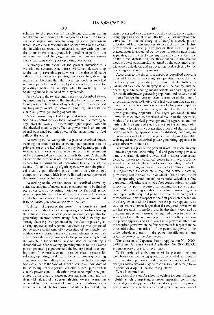
US 6,480,767 B2 59
Solution to the problem of insufficient charging during highly efficient running. In the region of a lower limit to the uSable charging condition, by adopting a configuration in which selects the threshold value So that even in the condi tion in which the prescribed physical quantity with regard to the prime motor is not good, it is possible to perform the minimum required charging, it is possible to prevent unnec essary charging under poor operating conditions. A twenty-eighth aspect of the present invention is a
variation on a control System for a hybrid vehicle according to the twenty-Seventh aspect, wherein the threshold value calculator comprises an operating mode Switching detecting means for detecting that the operating mode is Switched within a predetermined time, hysteresis Setting means for providing threshold value output when the Switching of the operating mode is detected with hysteresis.
According to the twenty-eighth aspect as described above, by imparting hysteresis to the threshold value, it is possible to Suppress a deterioration of operating performance caused by frequency Switching between operating modes of the electrical power generating apparatus. A twenty-ninth aspect of the present invention is a varia
tion on a control System for a hybrid vehicle according to any one of the twenty-fifth to twenty-eighth aspects, wherein the physical quantity per effective power rate is an amount of fuel consumed per unit power of the prime motor or fuel cell, or the engine.
According to the twenty-ninth aspect as described above, by using the amount of fuel consumed per power rate in the prime motor or the fuel cell as the physical quantity per unit work rate, it is possible to achieve a reduction in the amount of fuel consumed in comparison with the past. A thirtieth aspect of the present invention is a variation on a control System for a hybrid vehicle according to any one of the twenty-fifth to the twenty-eighth aspects, wherein the physi cal quantity per effective power rate is an exhaust gas component amount which is to be limited per unit power of the prime motor or fuel cell, or the engine.
According to the thirtieth aspect as described above, by using the amount of an exhaust gas component to be limited per power rate in the prime motor or the fuel cell as the physical quantity per unit work rate, it is possible to achieve a reduction in the amount of the exhaust gas component that it to be limited, in comparison with the past. A thirty-first aspect of the present invention is a control
System for a hybrid vehicle comprising a motor for allowing the vehicle to run, an electric power generating apparatus for generating electric power using fuel, and a battery for Storing electric power generated by the electric power gen erating apparatus and regenerative electric power generated by the motor at the time of deceleration of the vehicle, the control System comprising a consumed electric power cal culator for calculating current electric power consumption of the vehicle, a threshold value calculator for calculating a threshold value for Selecting operating modes for the electric power generating apparatus and the battery based on charg ing State of the battery, operating mode Selecting means for Selecting operating mode for the electric power generating apparatus and the battery based on effective fuel consump tion rate curve at the time of direct distribution indicative of fuel consumption rate per unit effective electric power when electric power equal to electric power consumption is gen erated by the electric power generating apparatus, and the threshold value, and the current electric power consumption obtained by the consumed electric power calculator, and a target generated electric power calculator for calculating
15
25
35
40
45
50
55
60
65
60 target generated electric power of the electric power gener ating apparatus based on an effective fuel consumption rate curve at the time of charging of Surplus electric power indicative of fuel consumption rate per unit effective electric power when electric power greater than electric power consumption is generated by the electric power generating apparatus, effective fuel consumption rate curve at the time of the direct distribution, the threshold value, the current electric power consumption obtained by the consumed elec tric power calculator, and an operating mode Selected by the operating mode Selecting means.
According to the thirty-first aspect as described above, a threshold value for Selecting an operating mode for the electrical power generating apparatus and the battery is calculated based on the charging State of the battery, and the operating mode Selecting means Selects an operating mode for the electric power generating apparatus and battery based on an effective fuel consumption rate curve at the time of direct distribution indicative of a fuel consumption rate per unit effective electric power when an electric power equal to consumed electric power is generated by the electrical power generating apparatus. The target generated electric power is calculated as described above, and the operating modes of the electrical power generating apparatus and the battery during Supply of electric power to the running motor and target electric power generation amount of the electrical power generating apparatus are established, enabling an increase or a reduction in the prescribed physical quantity with regard to the electrical power generating apparatus in comparison with the past.
Yet another aspect of the present invention is one having a power apparatus consuming fuel and generating power, a battery storing electrical power, and a motor converting electrical power to mechanical power transmitted to a drive wheel of the vehicle, the control System including a detector detecting a running condition of the vehicle. This controller is programmed to: calculate a required power indicating power required to drive the drive wheel of the vehicle, based on an operating condition of the vehicle, calculate a first parameter indicating a ratio of a fuel consumption rate with respect to the power required for running the power appa ratus under operating conditions in which power is gener ated equal to the required power to drive the vehicle, Set a threshold value with respect to the first parameter, based on the charging State of the battery; run the power apparatus So as to generate a power larger than the required power when the first parameter is Smaller than the threshold value, and of the generated power transmit the required power to the drive wheel, and Store the remaining power in the battery; and run the power apparatus So as to generate a power Smaller than the required power when the first parameter is larger than the threshold value, transmit all of the generated power to the drive wheel, and transmit the power insufficient amount from the battery to the drive wheel. The contents of Japanese Patent Application No. 2000
289355 and Japanese Patent Application No 2000-387832 are incorporated herein by reference. While preferred embodiments of he present invention
have been described using Specific terms, Such description is for illustrative purposes, and it is to be understood that changes and variations may be made without departing from the Spirit or Scope of the following claims. What is claimed is: 1. A control system for a hybrid vehicle for controlling the
hybrid vehicle comprising a power apparatus consuming fuel and generating power, a battery Storing electrical power, and a motor converting electrical power to mechanical

claim 2, further programmed to;
US 6,480,767 B2 61
power transmitted to a drive wheel of the vehicle, the control System including a detector detecting an operating condition of the vehicle, and programmed to:
calculate a required power indicating a power required to drive the vehicle, based on the operating condition of 5 the vehicle;
calculate a first parameter indicating a ratio between a fuel consumption rate and the required power for running the power apparatus So as to generate a power equal to the required power;
Set a threshold value with respect to the first parameter, based on a charging State of the battery;
run the power apparatus So as to generate a power larger than the required power when the first parameter is Smaller than the threshold value, and transmit part of the power generated to the drive wheel, and Store a remainder of the power generated in the battery; and
run the power apparatus So as to generate a power Smaller than the required power when the first parameter is larger than the threshold value, and transmit all of the power generated to the drive wheel, and transmit part of a power stored in the battery to the drive wheel.
2. A control System for a hybrid vehicle according to
15
claim 1, further programmed to: run the power apparatus at an operating condition under which a Second parameter coincides with the threshold value when the first parameter is Smaller than the threshold value, the Second parameter indicating a ratio between a fuel consumption rate and an effective power for running the power apparatus So as to generate a power larger than the required power, the effective power indicating a Sum of the required power and an uSable power indicating part of the remainder of the power generated.
3. A control System for a hybrid vehicle according to
25
35
calculate a charging efficiency and discharging efficiency of the battery, based on the charging State of the battery; and
calculate the uSable power by multiplying the remainder of the power generated by the charging efficiency and the discharging efficiency.
4. A control System for a hybrid vehicle according to
40
claim 1, further programmed to; run the power apparatus at an operating condition under which a third parameter coincides with the threshold value when the first parameter is larger than the thresh old value when the first parameter is larger than the threshold value, the third parameter indicating a ratio between a fuel consumption rate and the power gener ated.
45
62 5. A control system for a hybrid vehicle according to
claim 1, further programmed to: Stop the running of the power apparatus when the first
parameter is larger than the threshold value. 6. A control System for a hybrid vehicle according to
claim 1, further programmed to: run the power apparatus So as to generate a power equal
to the required power when the first parameter is equal to the threshold value, and transmit all of the power generated to the drive wheel.
7. A control system for a hybrid vehicle according to claim 1, further programmed to:
gradually reduce the threshold value when actual charging State of the battery is greater than the target charging State, and gradually increase the threshold value when the actual charging State of the battery is less than the target charging State.
8. A control system for a hybrid vehicle according to claim 1, further programmed to:
reduce the threshold value more, the greater is the actual charging State of the battery.
9. A control system for a hybrid vehicle according to claim 1, further programmed to:
compensate the threshold value with respect to a tem perature of the battery.
10. A control system for a hybrid vehicle according to claim 1, wherein the power apparatus comprises an engine consuming fuel and generating mechanical power, and a generator converting mechanical power generated by the engine to electric power.
11. A control System for a hybrid vehicle according to claim 1, wherein the power apparatus comprises an engine consuming fuel and generating mechanical power, and wherein the hybrid vehicle further comprises a transmission transmitting mechanical power generated by the engine to a drive wheel of the vehicle.
12. A control System for a hybrid vehicle according to claim 1, wherein the power apparatus comprises an engine consuming fuel and generating mechanical power, and a generator converting mechanical power generated by the engine to electric power, and wherein the hybrid vehicle further comprises a transmission transmitting mechanical power generated by the engine to a drive wheel of the vehicle.
13. A control system for a hybrid vehicle according to claim 1, wherein the power apparatus is a fuel cell consum ing fuel and generating electric power.
k k k k k