IUMRS-ICAM 2015_Selective Oxidation AHSS and UHSS_OCT 25-29_2015
Upload
sathish-kumarCategory
view
220download
0
7/27/2019 12 - Joe Meyecic - AHSS Tooling Technologies
http://slidepdf.com/reader/full/12-joe-meyecic-ahss-tooling-technologies 1/32
w w w . a u t o s t e e l . o r g
Die Development for AHSSCase StudyJoe Meyecic
Diversified Tooling Group
7/27/2019 12 - Joe Meyecic - AHSS Tooling Technologies
http://slidepdf.com/reader/full/12-joe-meyecic-ahss-tooling-technologies 2/32
w w w . a u t o s t e e l . o r g
Diversified Tooling Group
Superior
Cam
Superior Cam has established
itself as a technical leader in the
Prototype Sheet Metal Industry
during the past 30 years. We have
built a reputation as an innovative,
experienced and reliable full service
operation which emphasizes
production intent quality at every
step of the tooling process.
Midland
Design
Midland Design has 40 years of
experience designing all types of
vehicle sheet metal stamping dies.
Midland Design is regarded as a
leader in the field of “Solid CAD Die
Design.”
Bespro
Pattern
During the past 45 years Bespro
Pattern has developed an excellentreputation for quality, timing and
competitive prices. We are a
respected leader in the CNC
machining of poly patterns off solid
CAD die design.
American
Tooling
Center
American Tooling Center is a modernstate-of-the-art Tool and Die facility.
Our full service operation was
designed and constructed in 1989 as
a world class production die facility
which emphasizes a CAD/CAM/CNC
utilization.
4 companies
1 goal:
Full Service
2
7/27/2019 12 - Joe Meyecic - AHSS Tooling Technologies
http://slidepdf.com/reader/full/12-joe-meyecic-ahss-tooling-technologies 3/32
w w w . a u t o s t e e l . o r g
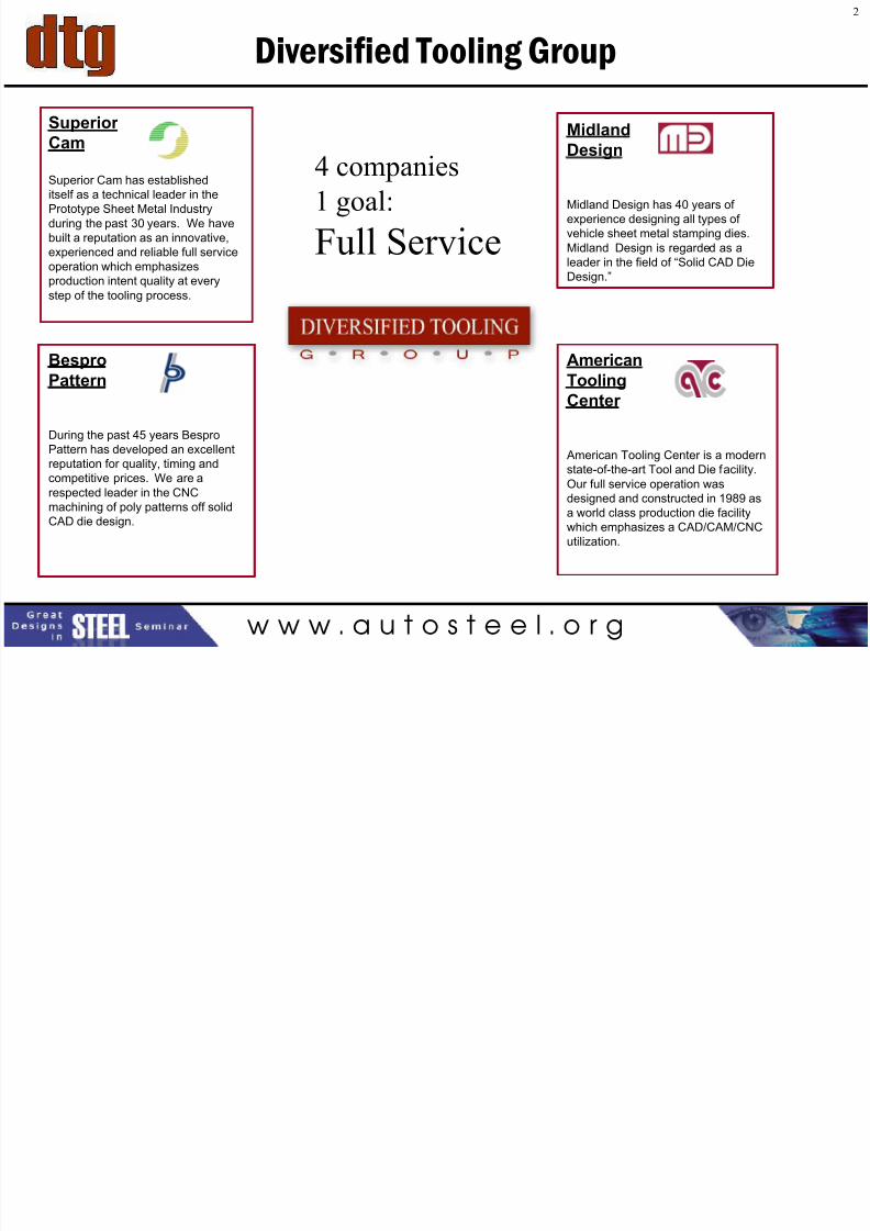
Defining the Part
• Fiat 500 Cabrio C-Pillar
• Material Specs:
– 1.2mm gage
– Dual Phase 590 steel
3
7/27/2019 12 - Joe Meyecic - AHSS Tooling Technologies
http://slidepdf.com/reader/full/12-joe-meyecic-ahss-tooling-technologies 4/32
w w w . a u t o s t e e l . o r g
C-Pillar Concerns
• Dimensional Tolerance
• Edge Fractures
• Splits
• Zinc Pick-up
• Excessive Die Wear
• Excessive Tonnage Requirements
4
7/27/2019 12 - Joe Meyecic - AHSS Tooling Technologies
http://slidepdf.com/reader/full/12-joe-meyecic-ahss-tooling-technologies 5/32
w w w . a u t o s t e e l . o r g
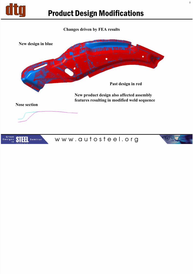
Product Design Modifications
Changes driven by FEA results
Past design in red
New design in blue
Nose section
New product design also affected assembly
features resulting in modified weld sequence
5
7/27/2019 12 - Joe Meyecic - AHSS Tooling Technologies
http://slidepdf.com/reader/full/12-joe-meyecic-ahss-tooling-technologies 6/32
w w w . a u t o s t e e l . o r g
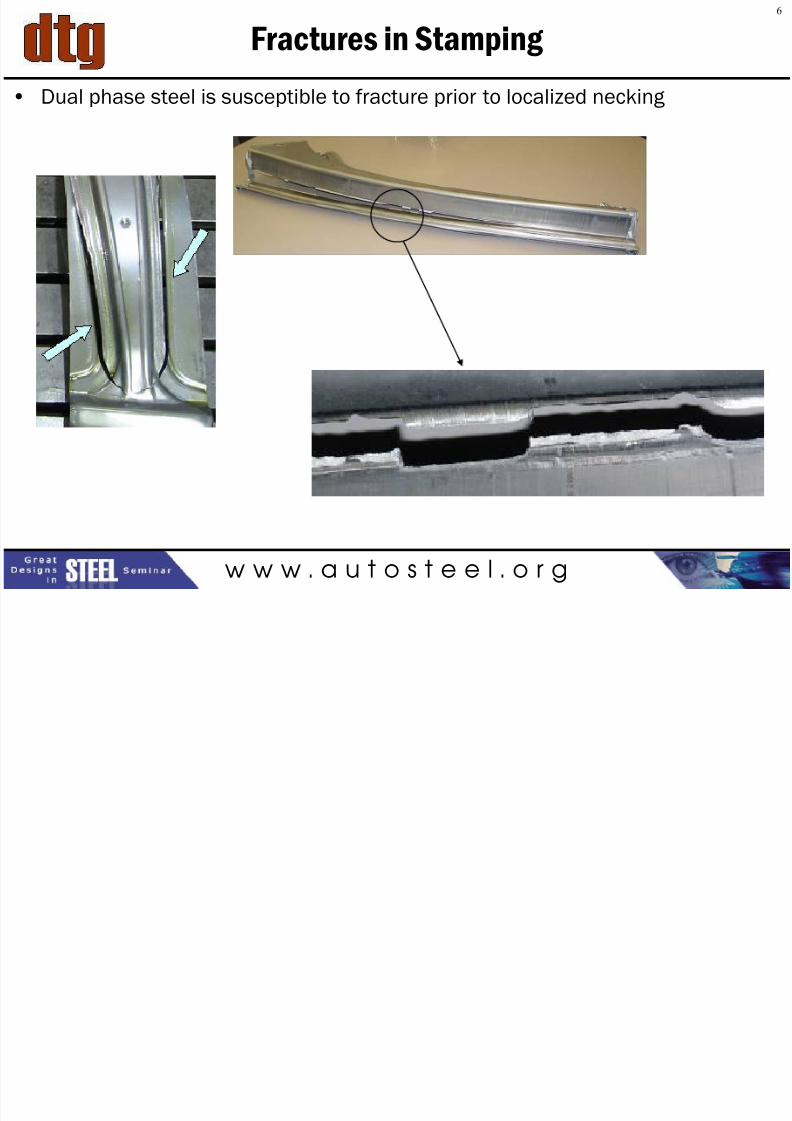
Fractures in Stamping
• Dual phase steel is susceptible to fracture prior to localized necking
6
7/27/2019 12 - Joe Meyecic - AHSS Tooling Technologies
http://slidepdf.com/reader/full/12-joe-meyecic-ahss-tooling-technologies 7/32w w w . a u t o s t e e l . o r g
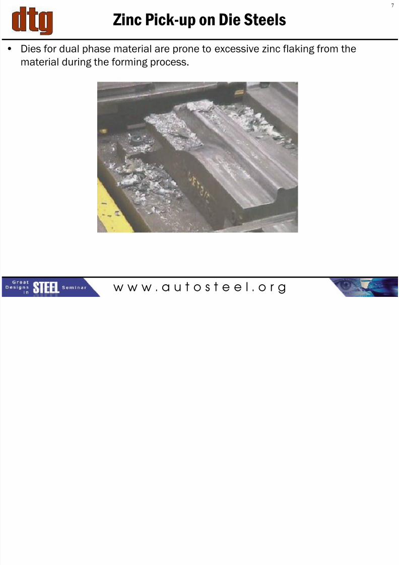
Zinc Pick-up on Die Steels
• Dies for dual phase material are prone to excessive zinc flaking from the
material during the forming process.
7
7/27/2019 12 - Joe Meyecic - AHSS Tooling Technologies
http://slidepdf.com/reader/full/12-joe-meyecic-ahss-tooling-technologies 8/32w w w . a u t o s t e e l . o r g
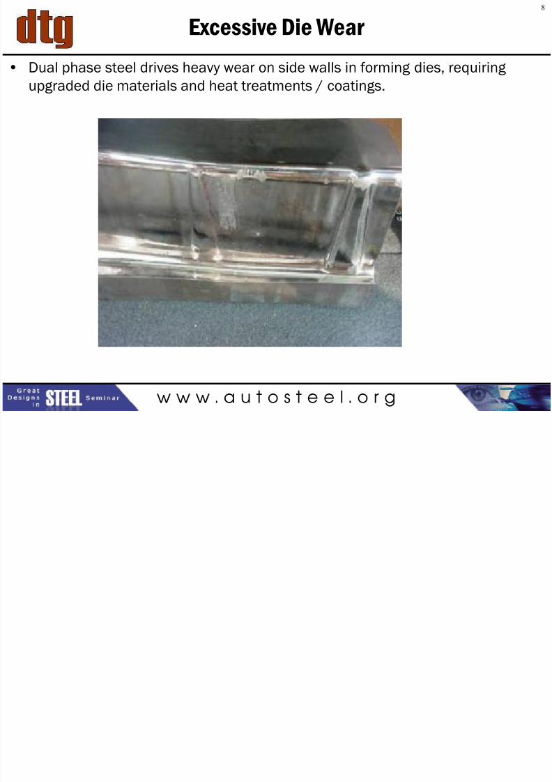
Excessive Die Wear
• Dual phase steel drives heavy wear on side walls in forming dies, requiring
upgraded die materials and heat treatments / coatings.
8
7/27/2019 12 - Joe Meyecic - AHSS Tooling Technologies
http://slidepdf.com/reader/full/12-joe-meyecic-ahss-tooling-technologies 9/32w w w . a u t o s t e e l . o r g
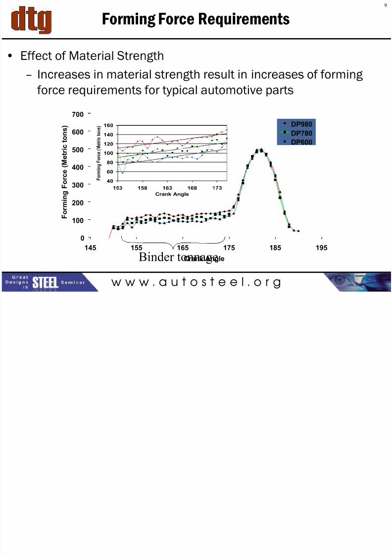
Forming Force Requirements
• Effect of Material Strength
– Increases in material strength result in increases of forming
force requirements for typical automotive parts
40
60
80
100
120140
160
153 158 163 168 173
Crank Angle
F o r m i n g F o r c e ( M e t r i c
t o n s )
0
100
200
300
400
500
600
700
145 155 165 175 185 195
Crank Angle
F o r m
i n g F o r c e ( M e t r i c t o n s ) DP980
DP780
DP600
Binder tonnage
9
7/27/2019 12 - Joe Meyecic - AHSS Tooling Technologies
http://slidepdf.com/reader/full/12-joe-meyecic-ahss-tooling-technologies 10/32w w w . a u t o s t e e l . o r g
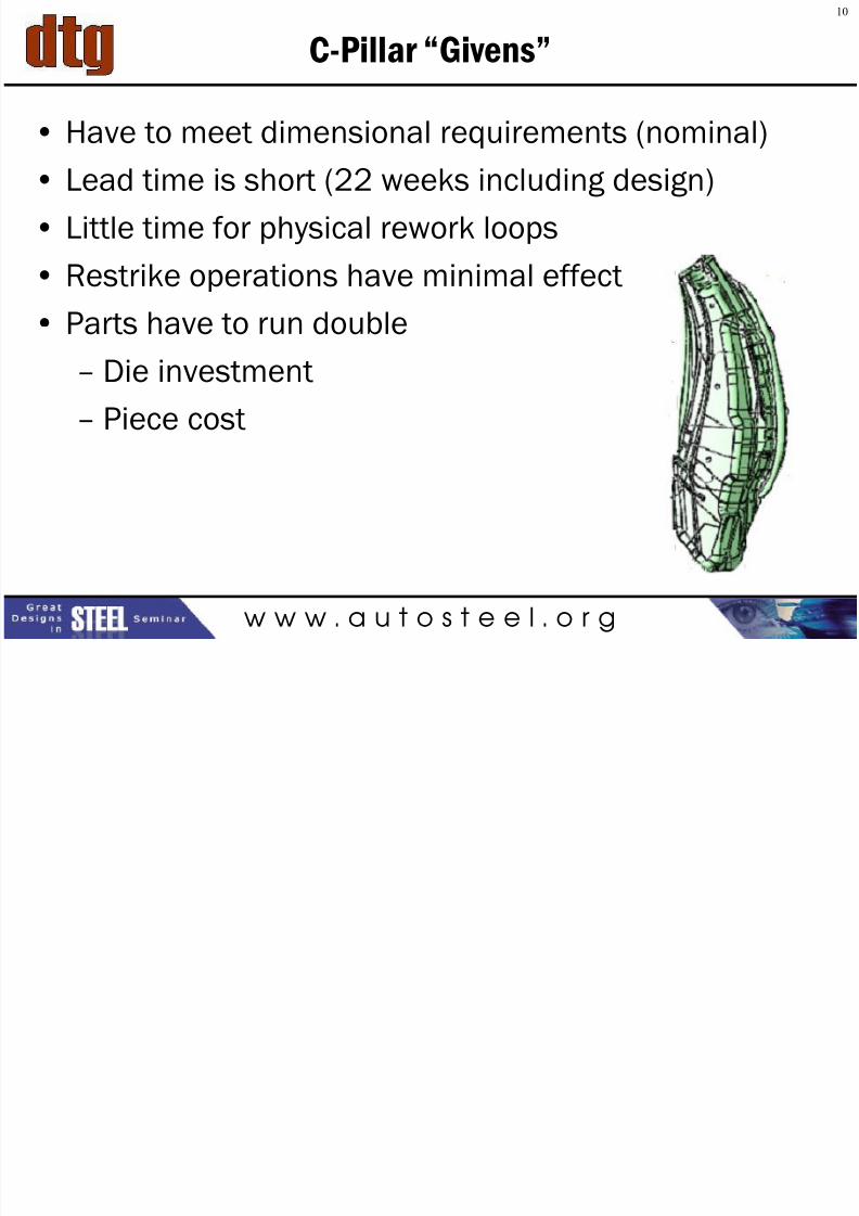
C-Pillar “Givens”
• Have to meet dimensional requirements (nominal)
• Lead time is short (22 weeks including design)
• Little time for physical rework loops
• Restrike operations have minimal effect
• Parts have to run double
– Die investment
– Piece cost
10
7/27/2019 12 - Joe Meyecic - AHSS Tooling Technologies
http://slidepdf.com/reader/full/12-joe-meyecic-ahss-tooling-technologies 11/32w w w . a u t o s t e e l . o r g
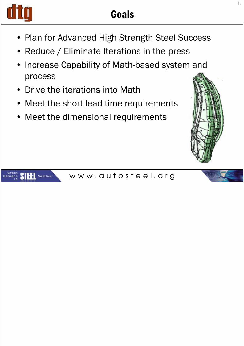
Goals
• Plan for Advanced High Strength Steel Success
• Reduce / Eliminate Iterations in the press
• Increase Capability of Math-based system and
process
• Drive the iterations into Math
• Meet the short lead time requirements
• Meet the dimensional requirements
11
7/27/2019 12 - Joe Meyecic - AHSS Tooling Technologies
http://slidepdf.com/reader/full/12-joe-meyecic-ahss-tooling-technologies 12/32w w w . a u t o s t e e l . o r g
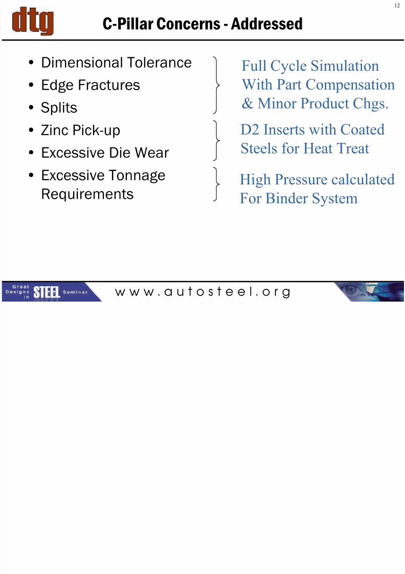
C-Pillar Concerns - Addressed
• Dimensional Tolerance
• Edge Fractures
• Splits
• Zinc Pick-up
• Excessive Die Wear
• Excessive Tonnage
Requirements
Full Cycle SimulationWith Part Compensation
& Minor Product Chgs.
D2 Inserts with Coated
Steels for Heat Treat
High Pressure calculated
For Binder System
12
13
7/27/2019 12 - Joe Meyecic - AHSS Tooling Technologies
http://slidepdf.com/reader/full/12-joe-meyecic-ahss-tooling-technologies 13/32w w w . a u t o s t e e l . o r g
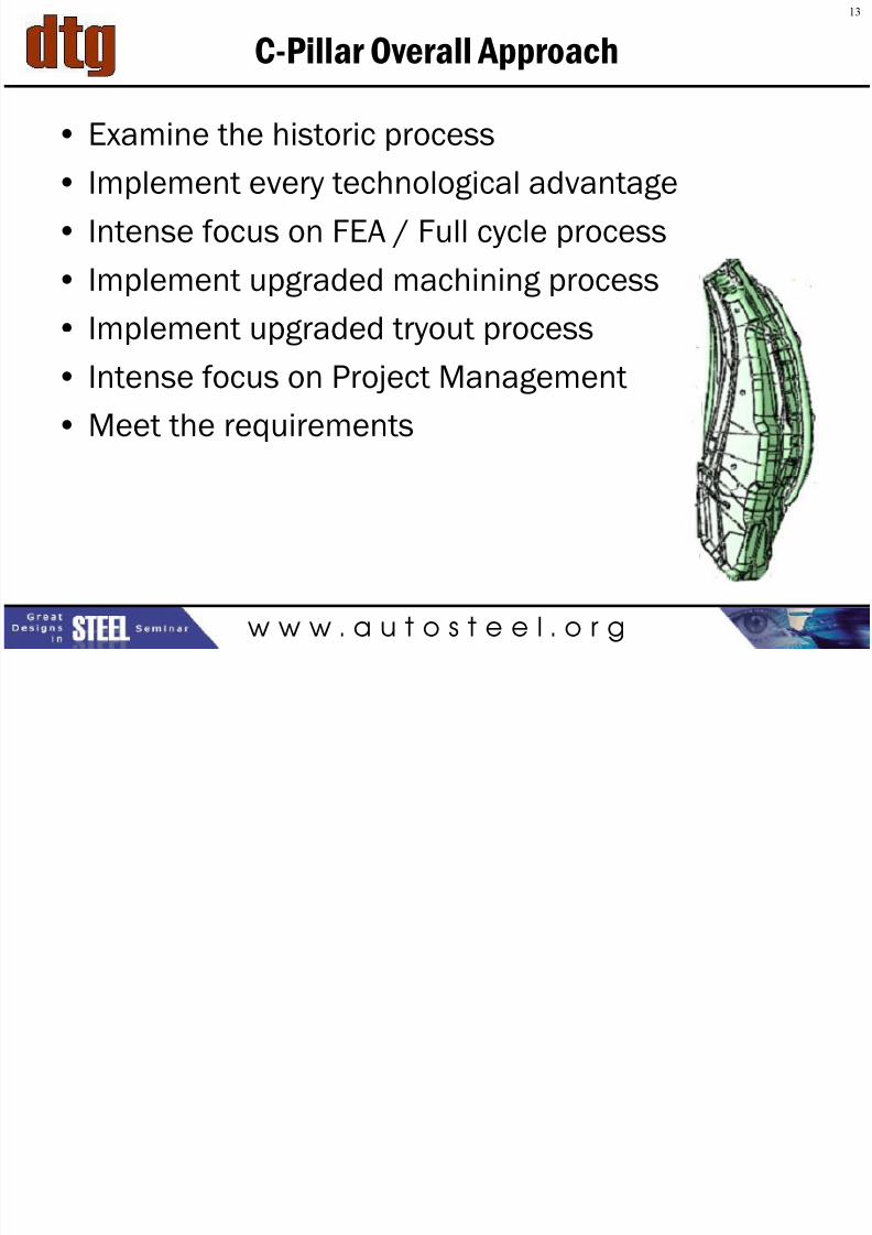
C-Pillar Overall Approach
• Examine the historic process
• Implement every technological advantage
• Intense focus on FEA / Full cycle process
• Implement upgraded machining process
• Implement upgraded tryout process
• Intense focus on Project Management
• Meet the requirements
13
14
7/27/2019 12 - Joe Meyecic - AHSS Tooling Technologies
http://slidepdf.com/reader/full/12-joe-meyecic-ahss-tooling-technologies 14/32w w w . a u t o s t e e l . o r g
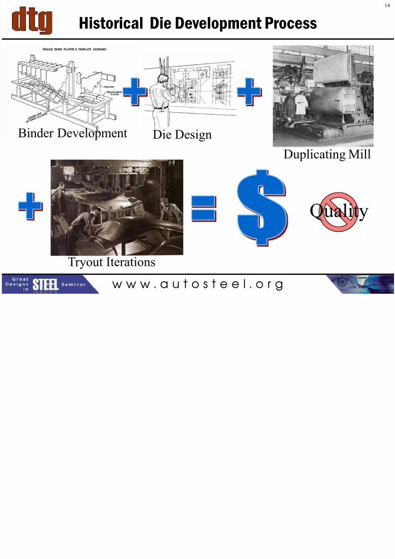
Historical Die Development Process
Quality
Binder Development Die DesignDuplicating Mill
Tryout Iterations
14
15
7/27/2019 12 - Joe Meyecic - AHSS Tooling Technologies
http://slidepdf.com/reader/full/12-joe-meyecic-ahss-tooling-technologies 15/32w w w . a u t o s t e e l . o r g
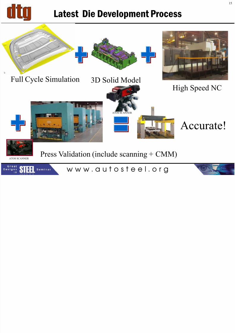
Latest Die Development Process
Accurate!
Full Cycle Simulation 3D Solid Model High Speed NC
Press Validation (include scanning + CMM)
15
ATOS SCANNER
ATOS SCANNER
16
7/27/2019 12 - Joe Meyecic - AHSS Tooling Technologies
http://slidepdf.com/reader/full/12-joe-meyecic-ahss-tooling-technologies 16/32
w w w . a u t o s t e e l . o r g
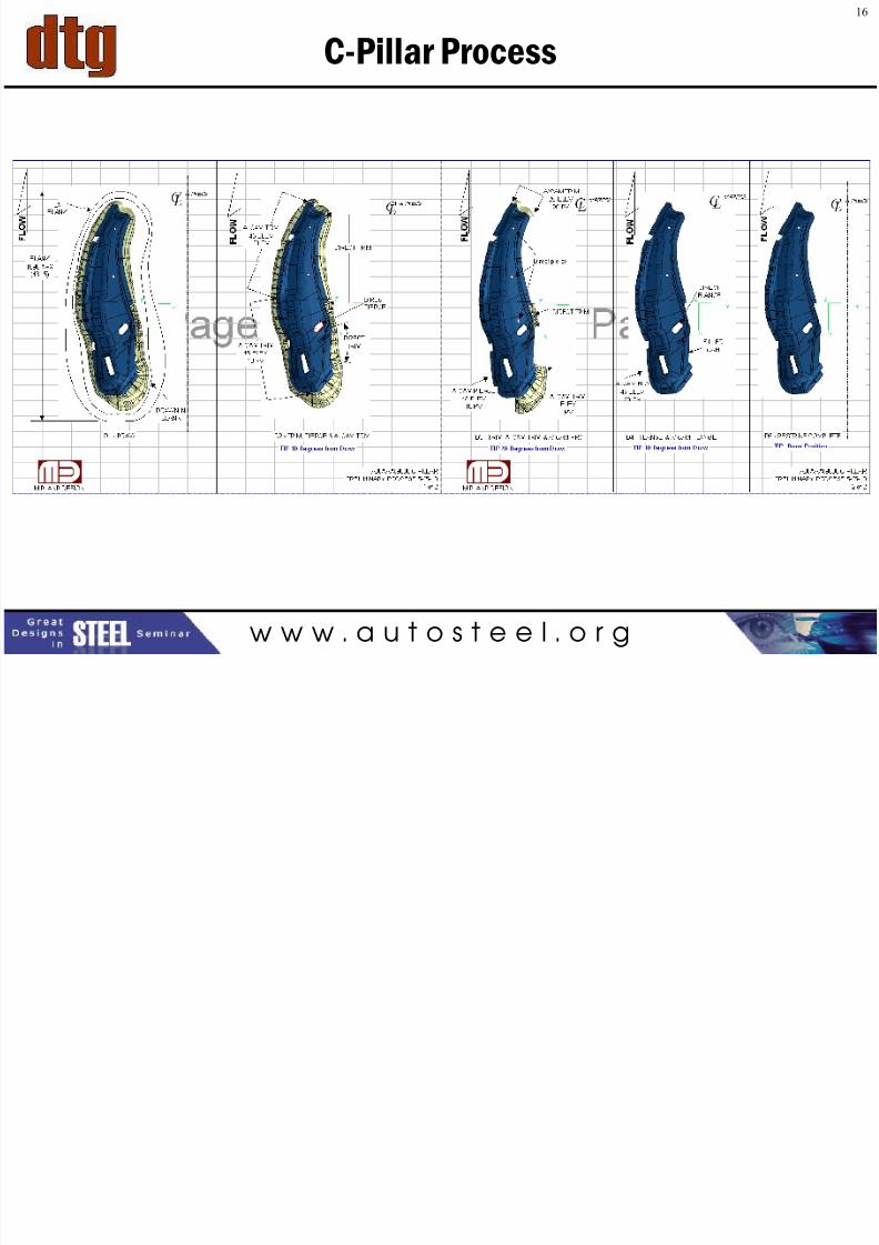
C-Pillar Process
16
17
7/27/2019 12 - Joe Meyecic - AHSS Tooling Technologies
http://slidepdf.com/reader/full/12-joe-meyecic-ahss-tooling-technologies 17/32
w w w . a u t o s t e e l . o r g
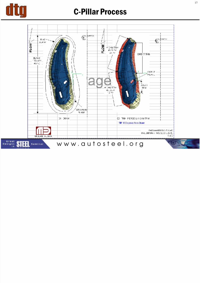
C-Pillar Process
17
18

7/27/2019 12 - Joe Meyecic - AHSS Tooling Technologies
http://slidepdf.com/reader/full/12-joe-meyecic-ahss-tooling-technologies 18/32
w w w . a u t o s t e e l . o r g
C-Pillar Process
18
19
7/27/2019 12 - Joe Meyecic - AHSS Tooling Technologies
http://slidepdf.com/reader/full/12-joe-meyecic-ahss-tooling-technologies 19/32
w w w . a u t o s t e e l . o r g
Forming Simulation
•Full Cycle Simulation per 3D Die Process– Analyze every operation in the line
–Morph required die faces to accommodate results
–
Iterate in math to get to nominal• Commercial Codes
• Proprietary Process and Methods
• Resolve forming issues in math (Virtual)
• Cut dies to morphed shape
• Inspect and compare to nominal
DTG Expertise to Highlight
19
20
7/27/2019 12 - Joe Meyecic - AHSS Tooling Technologies
http://slidepdf.com/reader/full/12-joe-meyecic-ahss-tooling-technologies 20/32
w w w . a u t o s t e e l . o r g
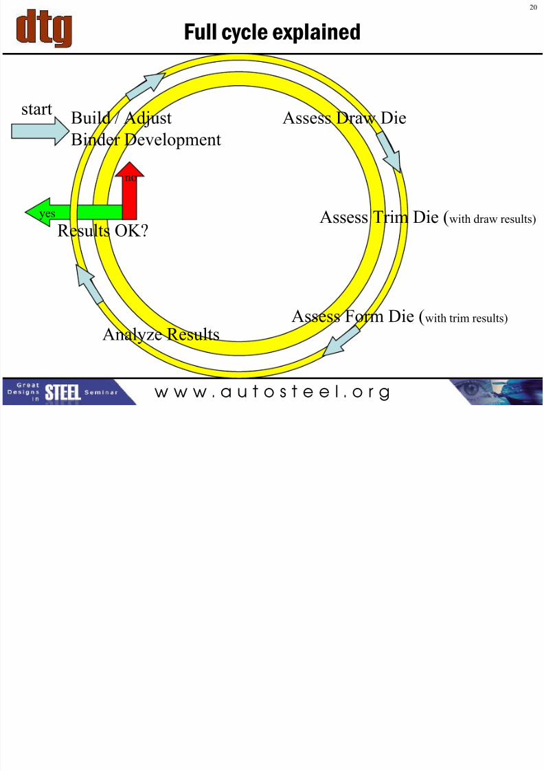
Full cycle explained
yes
no
Build / Adjust
Binder Development
Assess Draw Die
Assess Trim Die (with draw results)
Assess Form Die (with trim results)
Analyze Results
Results OK?
start
20
21
7/27/2019 12 - Joe Meyecic - AHSS Tooling Technologies
http://slidepdf.com/reader/full/12-joe-meyecic-ahss-tooling-technologies 21/32
w w w . a u t o s t e e l . o r g
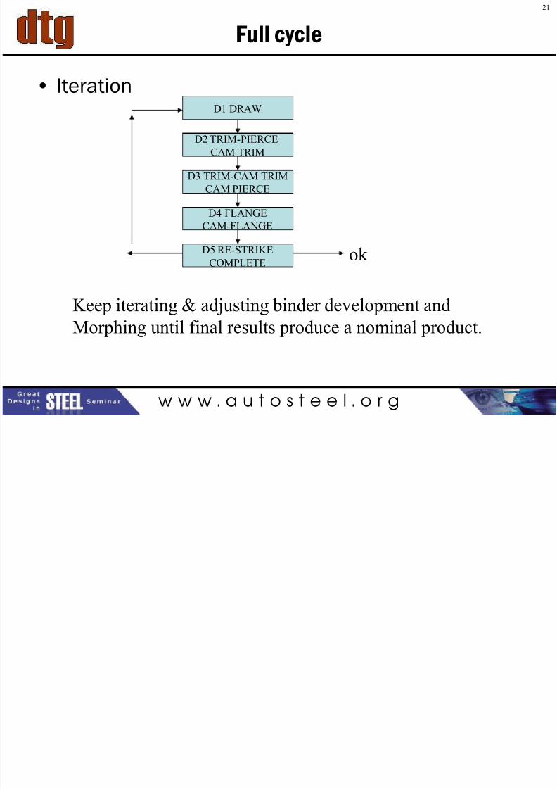
Full cycle
• IterationD1 DRAW
D2 TRIM-PIERCE
CAM TRIM
D5 RE-STRIKE
COMPLETE
D3 TRIM-CAM TRIM
CAM PIERCE
Keep iterating & adjusting binder development and
Morphing until final results produce a nominal product.
ok
D4 FLANGE
CAM-FLANGE
21
7/27/2019 12 - Joe Meyecic - AHSS Tooling Technologies
http://slidepdf.com/reader/full/12-joe-meyecic-ahss-tooling-technologies 22/32
7/27/2019 12 - Joe Meyecic - AHSS Tooling Technologies
http://slidepdf.com/reader/full/12-joe-meyecic-ahss-tooling-technologies 23/32
24
7/27/2019 12 - Joe Meyecic - AHSS Tooling Technologies
http://slidepdf.com/reader/full/12-joe-meyecic-ahss-tooling-technologies 24/32
w w w . a u t o s t e e l . o r g
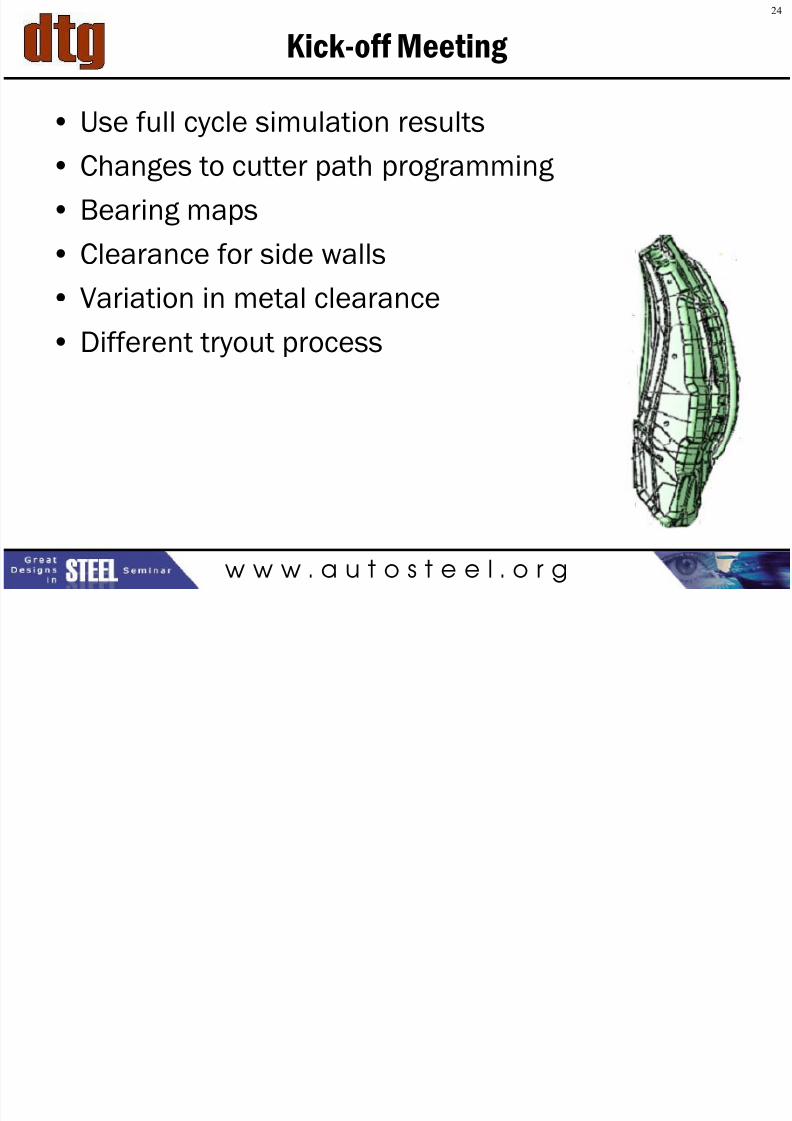
Kick-off Meeting
• Use full cycle simulation results
• Changes to cutter path programming
• Bearing maps
• Clearance for side walls
• Variation in metal clearance
• Different tryout process
25
7/27/2019 12 - Joe Meyecic - AHSS Tooling Technologies
http://slidepdf.com/reader/full/12-joe-meyecic-ahss-tooling-technologies 25/32
w w w . a u t o s t e e l . o r g
Tryout process changes
• Blank outline
• Blank location
• Binder tonnage / Ram tonnage
• Binder travel
• Lube
• Metal draw-in map
• Engineered beads per FEA force factor
Engineering = Design = Physical Reality
26
7/27/2019 12 - Joe Meyecic - AHSS Tooling Technologies
http://slidepdf.com/reader/full/12-joe-meyecic-ahss-tooling-technologies 26/32
w w w . a u t o s t e e l . o r g
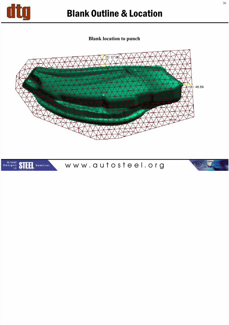
Blank Outline & Location
Blank location to punch
27
7/27/2019 12 - Joe Meyecic - AHSS Tooling Technologies
http://slidepdf.com/reader/full/12-joe-meyecic-ahss-tooling-technologies 27/32
w w w . a u t o s t e e l . o r g
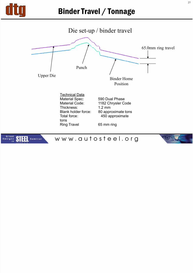
Binder Travel / Tonnage
Die set-up / binder travel
65.0mm ring travel
Punch
Binder Home
Position
Upper Die
Technical DataMaterial Spec: 590 Dual Phase
Material Code: 1182 Chrysler CodeThickness: 1.2 mmBlank holder force: 80 approximate tonsTotal force: 450 approximatetonsRing Travel 65 mm ring
28
7/27/2019 12 - Joe Meyecic - AHSS Tooling Technologies
http://slidepdf.com/reader/full/12-joe-meyecic-ahss-tooling-technologies 28/32
w w w . a u t o s t e e l . o r g
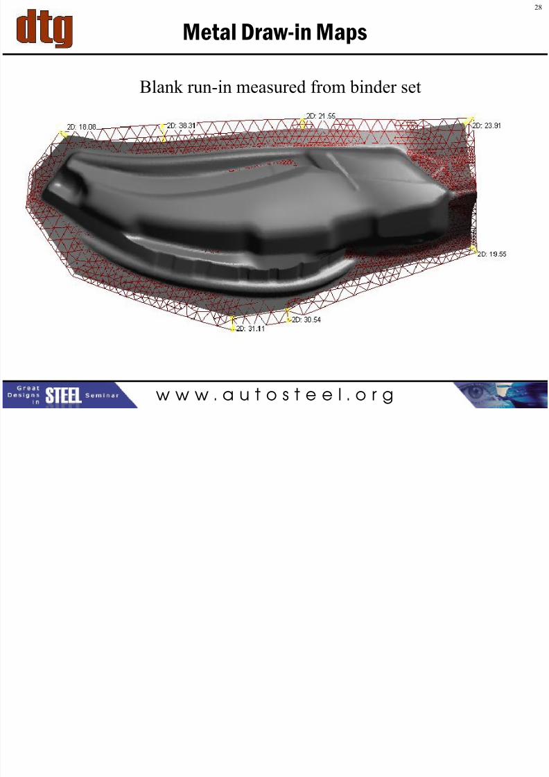
Metal Draw-in Maps
Blank run-in measured from binder set
29
7/27/2019 12 - Joe Meyecic - AHSS Tooling Technologies
http://slidepdf.com/reader/full/12-joe-meyecic-ahss-tooling-technologies 29/32
w w w . a u t o s t e e l . o r g
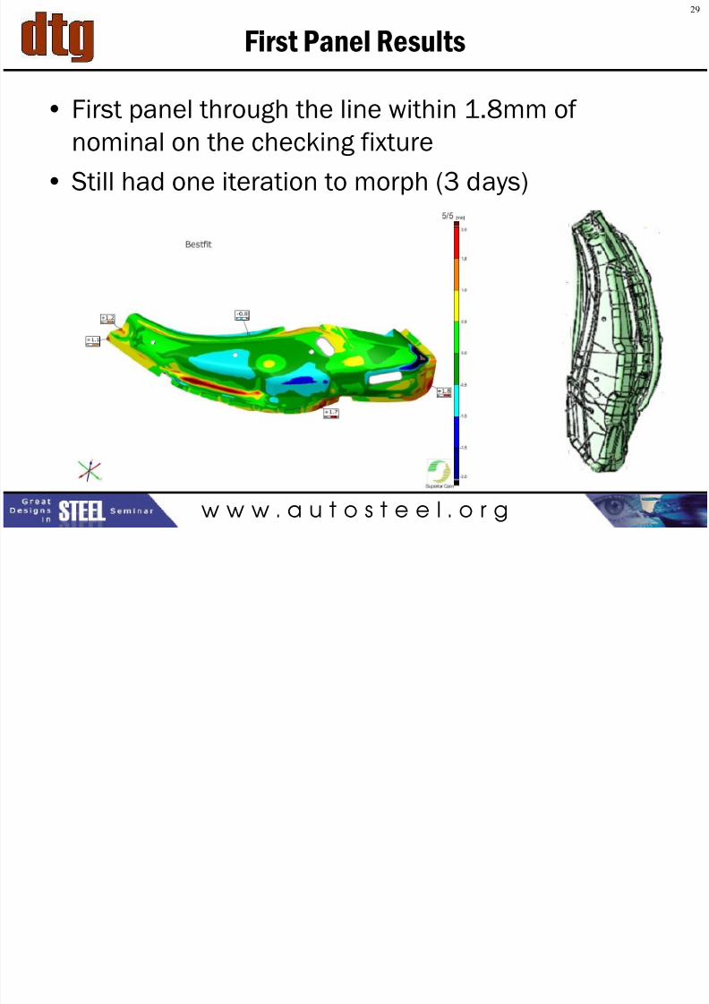
First Panel Results
• First panel through the line within 1.8mm of
nominal on the checking fixture
• Still had one iteration to morph (3 days)
30
7/27/2019 12 - Joe Meyecic - AHSS Tooling Technologies
http://slidepdf.com/reader/full/12-joe-meyecic-ahss-tooling-technologies 30/32
w w w . a u t o s t e e l . o r g
Process used for Iteration
• White Light Scan
• Color map inspection reports
• Morph 120% correction factor
• Re-cut
• Re-scan
• Results after morph = OK
Total lead time = 22 weeks, including die design
Part met nominal criteria
7/27/2019 12 - Joe Meyecic - AHSS Tooling Technologies
http://slidepdf.com/reader/full/12-joe-meyecic-ahss-tooling-technologies 31/32
7/27/2019 12 - Joe Meyecic - AHSS Tooling Technologies
http://slidepdf.com/reader/full/12-joe-meyecic-ahss-tooling-technologies 32/32