113504 Propagation Float Station - FarmTek · Prepare Propagation Tray PREPARE 111107 PROPAGATION...
13
Revision date: 01.27.20 ©2020 FarmTek ® All Rights Reserved. Reproduction is prohibited without permission. 113504 Propagation Float Station 113504 4' x 8' Station ATTENTION: ACTUAL TRAY IS BLACK. ORIGINAL WHITE TRAY IS NO LONGER AVAILABLE.
Transcript of 113504 Propagation Float Station - FarmTek · Prepare Propagation Tray PREPARE 111107 PROPAGATION...

1Revision date: 01.27.20
©2020 FarmTek®
All Rights Reserved. Reproduction is prohibited without permission.
113504Propagation Float Station
113504 4' x 8' Station
ATTENTION: ACTUAL TRAY IS BLACK. ORIGINAL WHITE TRAY IS NO LONGER AVAILABLE.

2 Revision date: 01.27.20
REQUIRED TOOLS
The following list identifies the main tools needed to assemble the system. Additional tools may be needed.
• Level (4'– recommended)
• Wrench set to level frame
• Ratchet with 1/2" socket to assemble frame
• 3/16" hex (Allen) wrench—preferably one that can be used in a socket to operate with a drill.
• Adjustable pliers and small hammer
• Gloves to handle tubing
• 1-3/8" hole saw bit
• Tool to cut 3/4" tubing
READ THIS DOCUMENT BEFORE YOU BEGINThank you for purchasing the 113504 Propagation and Float Station. When properly assembled and maintained, this system will provide years of reliable service. These instructions include helpful hints and important information needed for safe assembly. Please read and understand these instructions before you begin. If you have any questions during the assembly, contact customer service.
ASSEMBLY PROCEDURE
Following the instructions as presented will help ensure the proper assembly of your system. The steps outlining the assembly process are as follows:
1. Verify that all parts are included in the shipment. Notify customer service for questions or concerns. See below.
2. Read and understand these instructions and the information included with the shipment before you begin.
3. Gather the tools and assistants.
4. Assemble the system.
Important Information
SAFETY PRECAUTIONS
• Wear eye protection.
• Wear gloves when handling metal pipes.
• Use a portable GFCI (Ground Fault Circuit Interrupter) when working with power tools and cords.
112838 Tek Screw
FALB34B
112772
112770
109260
AC2804
AC2804
113030S01112477
FAME51B
FAG338B
PICTORIAL GUIDE
Larger parts may not be shown.
111303 111698
111301
111302

3Revision date: 01.27.20
1 ATTACH LEG TUBES
Assemble frame on a flat, level surface.
8-3/4"
8-3/4"
Assemble as shown. Legs are 8-3/4" from the end of each FT15G16L09000S1 tube.
FT15VMGL01800S1
FT15G16L09000S1
FT15VMGL01800S1
112772 Flat Head Bolt
8-3/4"
Attach Leg Tubes
Complete these steps to install each 112477 insert:
1. Add one FALB34B nut to threaded stud of each 113030S01 foot and attach one foot to each 112477 insert.
2. Slide one 112477 insert assembly into bottom of each 18" vertical leg tube. Tap gently with a small hammer if needed to seat in place.
3. Secure each insert to each tube using two (2) 112838 Tek screws. Install screws through leg tube and wall of the 112477 insert and not the open side of the insert. Install screws slightly off center line of the leg tube to prevent contact with threaded rod.
4. Adjust 113030S01 leveler so it is seated against threaded plate of insert and locknut. See diagram to the right.
112772 5/16" x 3" Flat
Head Bolt
112477
FALB34B
5. Secure leg tubes to the FT15G16L09000S1 tubes using the 112772 flat head bolts.
Bottom of Leg Tube
112477
FALB34B Locknut
113030S01
x
x
Steps 3 & 4

44 Revision date: 01.27.20
2Assemble Main Frame
ASSEMBLE MAIN FRAME
Assemble frame on a flat, level surface.
1. Use the FAG338B (5/16" x 3") hex head bolts and FAME51B flat washers to complete the frame assembly. Tighten all connections until snug.
2. Install one 112770 finishing cap in each horizontal frame tube. Gently tap into tube if needed.
3. Level the frame as needed. Tighten locknut against the insert plate to secure leveler.
STEP 3
112770
STEP 2
FD15CMGL04900S1
FD15CMGL04900S1
STEP 1
FAME51B
FAG338B

5Revision date: 01.27.20
3Prepare Propagation Tray
PREPARE 111107 PROPAGATION TRAY (4' x 8')
Complete these steps to drill the holes in the propagation tray.
1. With assistance, carefully flip the tray over on the assembled frame so the bottom is facing up.
2. At one end of the tray, locate the flat area with dimples that identify hole locations.
3. Using a 1-3/8" hole saw bit and a drill, carefully drill the bulkhead holes through the bottom of the propagation tray.
4. Clean debris from the tray and around the holes.
5. Continue with the installation of the bulkhead fittings.
ATTENTION: ACTUAL TRAY IS BLACK. ORIGINAL WHITE TRAY IS NO LONGER AVAILABLE.

66 Revision date: 01.27.20
4Install Bulkhead Fittings
INSTALL BULKHEAD FITTINGSSystem is equipped with two (2) 111301 bulkhead fittings which are used to connect the tray to the lower reservoir. Gather these parts and install the fittings:
• 111301 Bulkhead fittings (2)
1 3 42
1. Flip tray over so inside is facing up and center tray on frame.
2. Take one 111301 bulkhead fitting and verify that the fitting includes a washer.
3. Insert the fitting with washer through one of the holes.
4. Seat fitting tightly in the hole.
65 7
5. Take the bulkhead nut and turn it onto the threaded shaft. Tighten until fitting is snug. NOTE: Use a large pair of adjustable pliers if necessary. Do not overtighten the nut!
6. Repeat the steps to install the remaining bulkhead fitting. NOTE: Check both fitting nuts to ensure each is tight.
7. Inspect the assembled fittings to ensure that a washer is present on the inside between each fitting and the tray.
8. Continue with the next procedure.
Washer

7Revision date: 01.27.20
5Prepare Reservoir Lid
PREPARE RESERVOIR LID
Complete these steps to drill the holes in the propagation tray.
1. With assistance, carefully place the reservoir lid on supports for drilling. Do not drill the lid over the reservoir. Debris can damage the pump and contaminate the nutrient solution when reservoir is filled.
2. Drill two (2) holes in the flat area near the port hole using a 1-3/8" hole saw bit.
3. Clean debris from the lid and from around the holes and continue with the next procedure.

88 Revision date: 01.27.20
6Install Air Stones and Assemble In-Line Valves
INSTALL AIR STONES AND ASSEMBLE IN-LINE VALVES
1. Take the 110091 1/8" clear vinyl tubing and cut its length in half.
2. Attach one 5' tube to each 109260 air stone.
3. Place the stones and tubes inside the reservoir opposite where the water pump will be installed.
4. Place lid on reservoir and slide reservoir under the frame.
5. Cut two (2) three inch (3") pieces of 3/4" tubing (111627) and slide one onto each AC2804 in-line valve. ATTENTION: Verify the you assemble both valves the same.
6. Secure each connection using one 111698 ratchet clamp. Gently squeeze the clamp until you hear the clicks indicating that the clamp is tight. Do not overtighten. Doing so will damage the clamp teeth.
7. Slide another clamp over each valve assembly.
8. Attach one valve assembly to the pump side bulkhead attached to the propagation tray.
9. Verify that the tube is seated tightly on the fitting and secure using the ratchet clamp.
9Revision date: 01.27.20
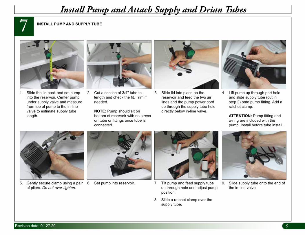
7 INSTALL PUMP AND SUPPLY TUBE
1. Slide the lid back and set pump into the reservoir. Center pump under supply valve and measure from top of pump to the in-line valve to estimate supply tube length.
2. Cut a section of 3/4" tube to length and check the fit. Trim if needed. NOTE: Pump should sit on bottom of reservoir with no stress on tube or fittings once tube is connected.
3. Slide lid into place on the reservoir and feed the two air lines and the pump power cord up through the supply tube hole directly below in-line valve.
4. Lift pump up through port hole and slide supply tube (cut in step 2) onto pump fitting. Add a ratchet clamp. ATTENTION: Pump fitting and o-ring are included with the pump. Install before tube install.
5. Gently secure clamp using a pair of pliers. Do not over-tighten.
6. Set pump into reservoir. 7. Tilt pump and feed supply tube up through hole and adjust pump position.
8. Slide a ratchet clamp over the supply tube.
9. Slide supply tube onto the end of the in-line valve.
Install Pump and Attach Supply and Drian Tubes

1010 Revision date: 01.27.20
7Install Pump and Attach Supply and Drian Tubes
INSTALL PUMP AND SUPPLY LINE AND DRAIN TUBE—continued
10. Secure connection by using pliers to squeeze the ratchet clamp.
11. Inspect assembly and ensure that tube and pump are aligned.
12. Take the remaining valve assembly and slide a ratchet clamp over the end.
13. Slide assembly onto the remaining bulkhead fitting and secure the connection as described in step 10.
14. Measure from valve to top of lid and add 2"-3" so tube when installed extends below the surface of the lid.
15. Cut a 3/4" tube to the length determined in the previous step.
16. Slide tube into the drain hole in the lid and add a ratchet clamp.
17. Attach tube to the in-line valve assembly.
18. Secure connection with clamp. 19. Inspect all connections to ensure they are tight to complete the assembly.
11Revision date: 01.27.20
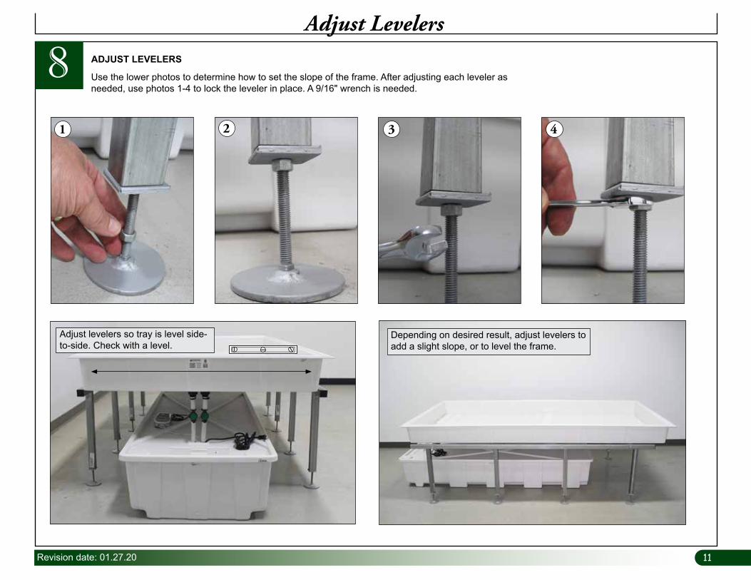
8Adjust Levelers
ADJUST LEVELERS
1 2 3 4
Depending on desired result, adjust levelers to add a slight slope, or to level the frame.
Use the lower photos to determine how to set the slope of the frame. After adjusting each leveler as needed, use photos 1-4 to lock the leveler in place. A 9/16" wrench is needed.
Adjust levelers so tray is level side-to-side. Check with a level.
1212 Revision date: 01.27.20
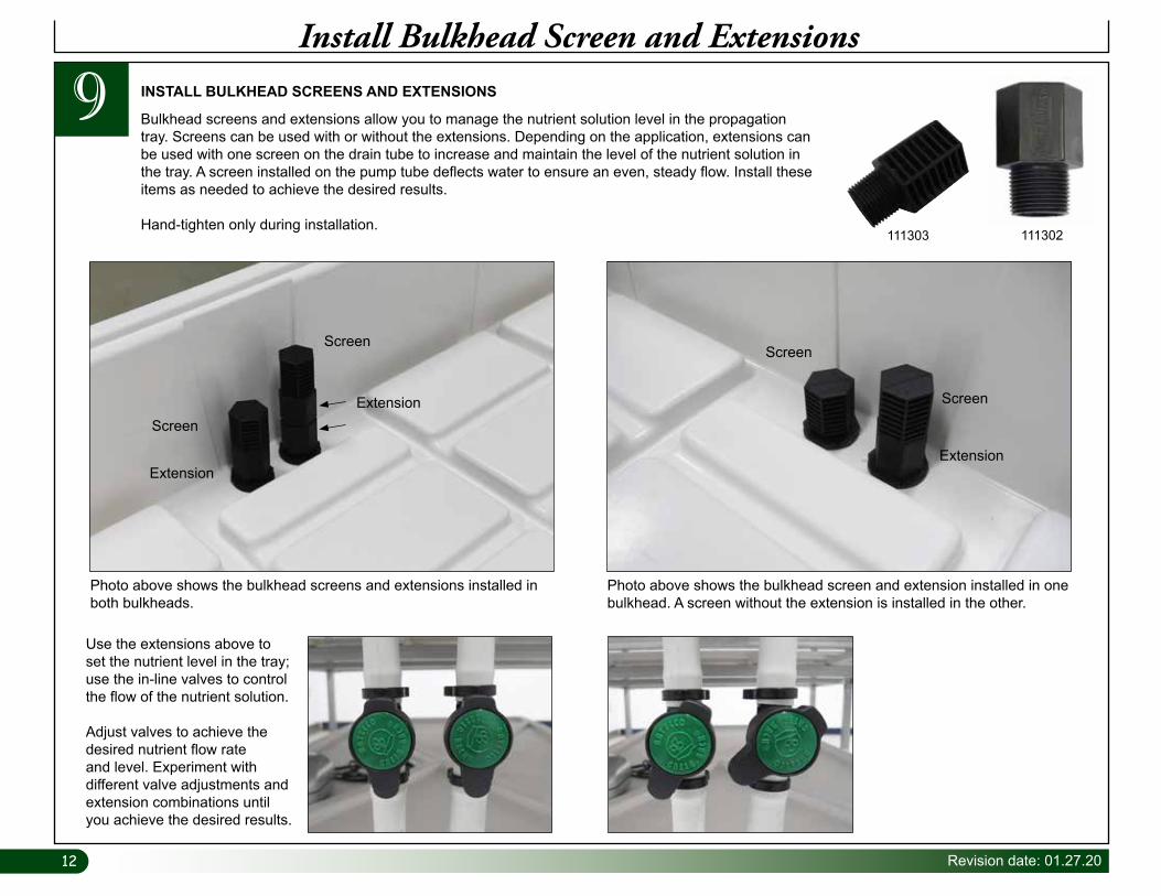
9Install Bulkhead Screen and Extensions
INSTALL BULKHEAD SCREENS AND EXTENSIONS
Photo above shows the bulkhead screens and extensions installed in both bulkheads.
Photo above shows the bulkhead screen and extension installed in one bulkhead. A screen without the extension is installed in the other.
111303 111302
Bulkhead screens and extensions allow you to manage the nutrient solution level in the propagation tray. Screens can be used with or without the extensions. Depending on the application, extensions can be used with one screen on the drain tube to increase and maintain the level of the nutrient solution in the tray. A screen installed on the pump tube deflects water to ensure an even, steady flow. Install these items as needed to achieve the desired results.
Hand-tighten only during installation.
Use the extensions above to set the nutrient level in the tray; use the in-line valves to control the flow of the nutrient solution.
Adjust valves to achieve the desired nutrient flow rate and level. Experiment with different valve adjustments and extension combinations until you achieve the desired results.
Screen
Screen
Extension
Screen
ScreenExtension
Extension

13Revision date: 01.27.20
PAGE RESERVED FOR CUSTOMER NOTES AND RECORDS