SECTION 2: Cable Tray - AWM : Home Page 2:5 E.&O.E. CABLE TRAY Continuous Punch Tray & Tray Fittings...
32
Page 2:1 www.kounis.com.au E.&O.E. CABLE TRAY SECTION 2: Cable Tray > 2:3 > 2:10 > 2:16 > 2:20 > 2:22 > 2:13 > 2:17 > 2:15 > 2:18 > 2:5 > 2:7 Admiralty Pattern Tray CT Heavy Duty Cable Tray Ladder Tray Covers/Trapese Supports Cable Mesh Tray Ladder Tray Ladder Tray Riser & Tee Mesh Tray Accessories Ladder Tray Accessories Ladder Tray Bend & Cross Continuous Punch Cable Tray Light Duty Tray
Transcript of SECTION 2: Cable Tray - AWM : Home Page 2:5 E.&O.E. CABLE TRAY Continuous Punch Tray & Tray Fittings...

Page 2:1www.kounis.com.au
E.&O.E.
CA
BLE T
RAY
SECTION 2: Cable Tray
> 2:3
> 2:10
> 2:16
> 2:20 > 2:22
> 2:13
> 2:17
> 2:15
> 2:18
> 2:5 > 2:7
Admiralty Pattern Tray
CT Heavy Duty Cable Tray
Ladder Tray Covers/Trapese Supports
Cable Mesh Tray
Ladder Tray
Ladder Tray Riser & Tee
Mesh Tray Accessories
Ladder Tray Accessories
Ladder Tray Bend & Cross
Continuous Punch Cable Tray Light Duty Tray

Page 2:2 www.kounis.com.au
E.&O.E.
Adm
iral
ity
Pat
tern
Tra
y G
ener
al D
escr
iption
Admiralty Pattern Tray
General Description
The Kounis Metal Industries Admiralty Pattern Tray System was developed
for use in general applications where installers are looking for an economical
option for cable management.
The fi nished product is constructed from 0.55 mm base material of
which there are two options; Galvabond and post production Hot Dip
Galvanised surface treatment. Both of which offer the following features:
the need for additional materials
ventilation and effi cient use of tray width
(made to order)
Painted fi nish is available on request.
CA
BLE T
RAY

Page 2:3www.kounis.com.au
E.&O.E.
Range Type Size Finish
KAP T 7 G
KAP = Admirality
Pattern Tray
T = Tray
TB = Bend
TT = Tee
TC = Cross
7 = 75 mm
G = Galvabond
H = Hot Dip Galv
P = Painted
Ordering example shown Admiralty Pattern tray 75 mm Galvabond
CA
BLE T
RAY
Adm
irality Pattern
Tray &
Fittings
“W”
14
20
2400
20 x 8 mm Slots
Joggled End
M6 nut & M6 x 12 Pan Head Screw
Fixings included
Provision for
Nylon Fixings
Fittings can be site
manufactured utilizing the
tray. Factory made fi ttings
can be manufactured on
request. Standard Fittings
Radius
Radius
Admiralty Pattern Tray
90° Bend Equal Cross
90° External Riser 90° Internal Riser
Admiralty Pattern Tray
Fittings Available on Request
Equal Tee
When Ordering
Page 2:4 www.kounis.com.au
E.&O.E.
KP
C C
AB
LE T
RAY
Continuous
Punch
Tra
yG
ener
al D
escr
iption
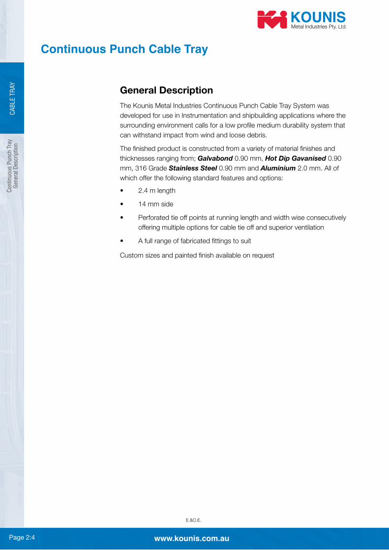
Continuous Punch Cable Tray
General Description
The Kounis Metal Industries Continuous Punch Cable Tray System was
developed for use in Instrumentation and shipbuilding applications where the
surrounding environment calls for a low profi le medium durability system that
can withstand impact from wind and loose debris.
The fi nished product is constructed from a variety of material fi nishes and
thicknesses ranging from; Galvabond 0.90 mm, Hot Dip Gavanised 0.90
Stainless Steel 0.90 mm and Aluminium which offer the following standard features and options:
offering multiple options for cable tie off and superior ventilation
Custom sizes and painted fi nish available on request
CA
BLE T
RAY

Page 2:5www.kounis.com.au
E.&O.E.
CA
BLE T
RAY
Contin
uous P
unch
Tray&
Tray Fittings
Continuous Punch Cable Tray
Cable Tray
50
150
“W”
150
“W”
150
“W”
R=300
“W”
150
50
Equal Tee
90° External Riser
90° Bend
26 x 7 mm Slot
M6 x 10 Gutter Bolt & Nut
Supplied With Splice Plate
Standard Length = 2.4 m
When Ordering
Range Type Size Finish
CP T 7 G
CP = Continous
Punch Cable
Tray
T = Tray 7 = 75 mm G = GalvabondB = Bend H = Hot Dip GalvTT = Tee A = AluminiumC = Cross S = Stainless Steel
P = Painted
Ordering example shown Continous Punch Tray 75 mm Galvabond

Page 2:6 www.kounis.com.au
E.&O.E.
Lig
ht
Duty
Tra
yG
ener
al D
escr
iption
Light Duty Tray
General Description
The Kounis Metal Industries Light Duty Tray System was developed for use
characteristics from a light series tray system.
The fi nished product is constructed from a variety of material fi nishes and
thicknesses; Galvabond Hot Dip Galvanised Stainless Steel 0.9 mm thick all sizes,
Aluminium features and options:
the need for additional materials
(splice plates required)
Painted fi nish and custom fi ttings available on request
CA
BLE T
RAY

Page 2:7www.kounis.com.au
E.&O.E.
CA
BLE T
RAY
'W'
Heig
ht
To
Ord
er
25
Dome CoverTo Order
Flat CoverTo Order
26 x 6.5 mmSlots
Gutter Bolts& Nuts Supplied
Lig
ht D
uty Tray
& Fittin
gs
Light Duty Tray
Light Duty Tray
Equal Cross Equal Tee
When Ordering
Range Type Size Finish
LD T 7 G
LD = Light Duty Cable Tray T = Tray 7 = 75 mm G = GalvabondTT = Tee H = Hot Dip GalvC = Cross A = AluminiumFC = Flat Cover S = Stainless SteelDC = Dome Cover (Height to order) P = Painted
Ordering example shown Light Duty Cable Tray 75 mm Galvabond

Page 2:8 www.kounis.com.au
E.&O.E.
KL L
IGH
T D
UTY
TR
AY
Lig
ht
Duty
Tra
y Fi
ttin
gs
Light Duty Tray
“W1”
“W2”
“W1”
“W2”
90° External Riser
Straight Reducer Offset Reducer Left
90° & 45° Bend
90° Internal Riser
When Ordering
Range Type Size Finish
LD B 7 G
LD = Light Duty Cable Tray B = Bend 7 = 75 mm G = Galvabond H = Hot Dip Galv
A = Aluminium S = Stainless Steel P = Painted
Ordering example shown Light Duty Cable Tray Bend 75 mm Galvabond

Page 2:9www.kounis.com.au
E.&O.E.
CA
BLE T
RAY
CT H
eavy Duty C
able Tray
Gen
eral Descrip
tion
CT Heavy Duty Cable Tray
General Description
The Kounis Metal Industries CT Heavy Duty Cable Tray System was
developed for use in mining and offshore applications and has been
designed for use in demanding locations where additional strength and
which there are four options; Mild Steel with post production Hot Dip
Galvanised surface treatment, Galvabond Stainless Steel
and Aluminium. All of which offer the following features:
no sharp edges
wise enabling wider cable bandings to be used as well as offering
superior ventilation
brackets
Custom sizes and painted fi nish available on request.

Page 2:10 www.kounis.com.au
E.&O.E.
CA
BLE T
RAY
CT H
eavy
Duty
Cab
le T
ray
CT Heavy Duty Cable Tray
15 Typ
40
“W”40
Cover
Length 2.4 m
Divider Strip Part
8 x 26 mm Slot
M6 Nut
M6 Flat Washer
Cover complete
with U-bolt
Hold Down Clamp,
Nuts & Washers
M6 x 25 mm Pan Head Screw
M6 Nut
M6 Spring Washer
M6 Washer
Top Hat
Insulating
bush
40 mm x 3 mm
Insulating pad
CT Cable Tray
Fixing and insulation where
dissimilar materials are used
When Ordering
Range Type Size Finish
CT T 7 G
CT = Heavy Duty
Cable Tray
T = Tray 7 = 75 mm G = GalvabondFC = Flat Cover H = Hot Dip GalvD = Divider A = AluminiumP = Splice Plate S = Stainless SteelIP = Insulating Pad P = PaintedIB = Insulating Bush
Ordering example shown Heavy Duty Cable Tray 75 mm Galvabond

Page 2:11www.kounis.com.au
E.&O.E.
CA
BLE T
RAY
CT H
eavy Duty C
able Tray
Fittings
CT Heavy Duty Cable Tray Fittings
"W"
40
150
80 80
150
"W1"
"W2"
"W1"
"W2"
"W"
150
80 80
150
Fixings Provided
90° Bend
Equal Cross
Straight Reducer
Offset Reducer
Equal Tee
Vertical Hinged Splice Plate
R 300
80
80
R300
80
80
90° Internal Riser 90° External Riser
When Ordering
Range Type Size Finish
CT B 7 G
CT = Heavy Duty
Cable Tray
B = Bend 7 = 75 mm G = GalvabondTT = Tee H = Hot Dip GalvC = Cross A = AluminiumVP = Vertical Hinge S = Stainless Steel
P = Painted
Ordering example shown Heavy Duty Cable Tray Bend 75 mm Galvabond

Page 2:12 www.kounis.com.au
E.&O.E.
Lad
der
Tra
yG
ener
al D
escr
iption
Ladder Tray
General Description
The Kounis Metal Industries Ladder Tray System was developed for use
in commercial and industrial applications where the installer demands
a cost effi cient site adaptable cable management system that can offer
enough strength and durability to carry light to medium duty cables whilst
maintaining an economical support span.
The fi nished product is constructed from 0.75 mm base material of
which there are two fi nish options; Galvabond and Mild Steel with post
production Hot Dip Galvanised surface treatment. System options are
KT3 Ladder Tray System – 50 mm high sided tray
KT5 Ladder Tray System – 85 mm high sided tray
All of which offer the following features or options:
changes
Painted fi nish available on request.
CA
BLE T
RAY
Page 2:13www.kounis.com.au
E.&O.E.
CA
BLE T
RAY
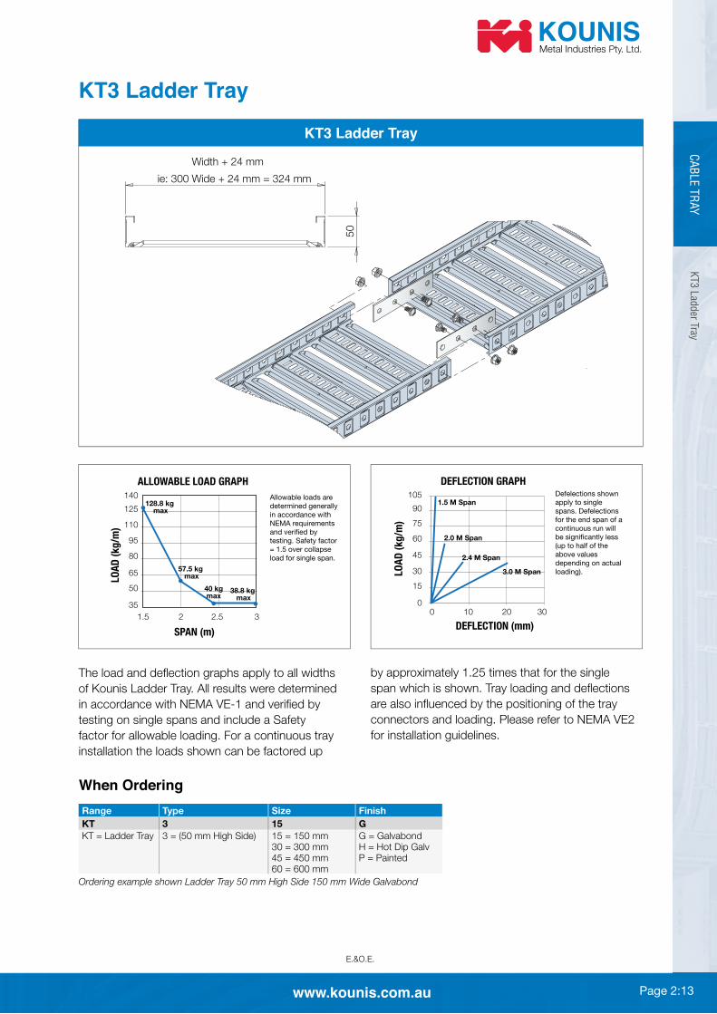
KT3 L
adder Tray
KT3 Ladder Tray
50
Width + 24 mm
ie: 300 Wide + 24 mm = 324 mm
KT3 Ladder Tray
of Kounis Ladder Tray. All results were determined
testing on single spans and include a Safety
factor for allowable loading. For a continuous tray
installation the loads shown can be factored up
ALLOWABLE LOAD GRAPH
SPAN (m)
LO
AD
(k
g/m
)
140
125
110
95
80
65
50
35
1.5 2 2.5 3
57.5 kg max
128.8 kg max
38.8 kg max
40 kgmax
Allowable loads are
determined generally
in accordance with
NEMA requirements
and verified by
testing. Safety factor
= 1.5 over collapse
load for single span.
DEFLECTION GRAPH
2.0 M Span
1.5 M Span
2.4 M Span
3.0 M Span
DEFLECTION (mm)
LO
AD
(k
g/m
)
100
0
15
30
45
60
75
90
105
20 30
Defelections shown
apply to single
spans. Defelections
for the end span of a
continuous run will
be significantly less
(up to half of the
above values
depending on actual
loading).
for installation guidelines.
When Ordering
Range Type Size Finish
KT 3 15 G
KT = Ladder Tray G = Galvabond H = Hot Dip Galv P = Painted
Ordering example shown Ladder Tray 50 mm High Side 150 mm Wide Galvabond

Page 2:14 www.kounis.com.au
E.&O.E.
CA
BLE T
RAY
KT5 L
adder
Tra
y
KT5 Ladder Tray
85
Width + 24 mm
ie: 300 Wide + 24 mm = 324 mm
KT5 Ladder Tray
of Kounis Ladder Tray. All results were determined
testing on single spans and include a Safety
factor for allowable loading. For a continuous tray
installation the loads shown can be factored up
ALLOWABLE LOAD GRAPH
SPAN (m)
LO
AD
(k
g/m
)
190
175
160
145
130
115
100
85
70
55
40
1.5 2 2.5 3
67.6 kg max
180.9 kg max
47.2 kg max
Allowable loads are
determined generally
in accordance with
NEMA requirements
and verified by
testing. Safety factor
= 1.5 over collapse
load for single span.
DEFLECTION GRAPH
LO
AD
(k
g/m
)
1.5 M Span
2.4 M Span
3.0 M Span
DEFLECTION (mm)
10 1550
0
20
40
60
80
100
120
140
160
20
Defelections shown
apply to single
spans. Defelections
for the end span of a
continuous run will
be significantly less
(up to half of the
above values
depending on actual
loading).
for installation guidelines.
When Ordering
Range Type Size Finish
KT 5 15 G
KT = Ladder Tray 5 = (85 mm High Side) G = Galvabond H = Hot Dip Galv P = Painted
Ordering example shown Ladder Tray 85 mm High Side 150 mm Wide Galvabond

Page 2:15www.kounis.com.au
E.&O.E.
CA
BLE T
RAY
Ladder Tray Accessories
Lad
der Tray A
ccessories
Ladder Tray Accessories
CODE: CODE: KT5SP
CODE: KTB
CODE: KTN
CODE: CODE: KT5LP
CODE:
CODE:
CODE:
CODE: KT5BS
CODE: KT5HDC
CODE:
CODE:
CODE:
KT3 Splice Plate KT5 Splice Plate
TX BracketTray Bolt
Tray Whizz Nut
KT3 Riser Link KT5 Riser Link Barrier Strip
Hold Down Clamp
Radius Plate
When Ordering
Range Type Size Finish
KT 3 SP G
KT = Ladder Tray SP = Splice Plate G = Galvabond5 = (85 mm High Side) HDC = Hold Down Clamp H = Hot Dip Galv
P = PaintedBS = Barrier Strip Z = Zinc Plated
B = Tray BoltN = Tray Nut
Ordering example shown Ladder Tray 50 mm High Side Splice Plate Galvabond

Page 2:16 www.kounis.com.au
E.&O.E.
Ladder Tray Covers/Trapeze Supports
Light Duty Trapeze Support Heavy Duty Trapeze Support
QTY. OF BENDS FROM 3 m LENGTH RADIUS PLATE
WIDTH BEND 90°
QTY. OF FITTINGS FROM 3 m TRAY LENGTH
WIDTH BEND 90° RISER 90° TEES
5 5
5 5
5 5
5 5
Note: Fastenings shown are for Tray Bolts and Nuts
and to suit the particular support installation.
Clamp details on
10
30°
Tek Screws
10-16 x 16 Wafertek
10
Peak Cover for KT3 & KT5 TrayFlat Cover for KT3 & KT5 Tray
Stock Material 0.75 mm
Galvabond all widths
Stock material HDG
Lad
der
Tra
y C
ove
rs/T
rapez
e S
upport
sC
AB
LE T
RAY
When Ordering
Range Type Size Finish
KT FC 15 G
KT = Ladder Tray FC = Flat Cover G = GalvabondPC = Peak Cover H = Hot Dip Galv
P = Painted
Ordering example shown Ladder Tray Flat Cover 150 mm Wide Galvabond fi nish.
When Ordering
Range Type Size Finish
KT LTS 15 G
KT =
Ladder
Tray
LTS = Light
Duty Support
HTS = Heavy
Duty Support
G = Galvabond H = Hot Dip Galv P = Painted
Ordering example shown Ladder Tray Light Duty Support
150 mm Galvabond fi nish.

Page 2:17www.kounis.com.au
E.&O.E.
CA
BLE T
RAY
Lad
derTray R
iser &
Tee Assem
bly
Ladder Tray Assembly Instructions
Internal Riser
Tee
External Riser
Nut
Bolt

Page 2:18 www.kounis.com.au
E.&O.E.
CA
BLE T
RAY
Lad
der
Tra
y B
end &
C
ross
Ass
embly
Ladder Tray Assembly Instructions
Bend
Plate
NOTE: KT KT5 plates and brackets are not interchangeable.
KTNZTX Bracket
KTBZ
Cross
Page 2:19www.kounis.com.au
E.&O.E.
CA
BLE T
RAY
Cab
le Mesh
TrayG
eneral D
escriptio
n
Cable Mesh
General Description
The Kounis Metal Industries Cable Mesh System was developed for use
in commercial and industrial applications where the installer demands
a cost effi cient site adaptable cable management system that can offer
enough strength and durability to carry light to medium duty cables whilst
maintaining an economical support span.
fi nish options; Zinc Plated and Hot Dip Galvanised. System options are
KM54 Cable Mesh System –
KT104 Cable Mesh System –
All of which offer the following features or options:
changes
damage is made to the cable when they are being installed
likelihood of vermin infestation
need for multiple tools
making for a cost effi cient install
Painted fi nish available on request.

Page 2:20 www.kounis.com.au
E.&O.E.
CA
BLE T
RAY
Cab
le M
esh T
ray
54 m
m
Cable Mesh – 54 mm
54
3 m
100
50
“W”
ALLOWABLE LOAD GRAPH
SUPPORT SPAN (m)
LO
AD
(k
g/m
)
20
40
60
80
100
120
140
0
1.5 2.1 2.2 2.3 2.4 2.51.6 1.7 1.8 1.9 2
“W4”
“W3”
“W2”
“W1”
“W4” – 400-600 mm
“W3” – 300 mm
“W2” – 150 mm
“W1” – 100 mm
KM 54 Tray
Support Span to the range Kounis Cable Mesh.
tray selection only and can vary with positioning of
connectors or site.
DEPTH: 50 mm inside
When Ordering
Range Type Size Finish
KM 54 10 Z
KM = Cable Mesh Z = Zinc Plated H = Hot Dip Galv P = Painted
50 = 500 mm
Ordering example shown Cable Mesh 54 mm High Side 100 mm Wide Zinc Plated
Page 2:21www.kounis.com.au
E.&O.E.
CA
BLE T
RAY
Cab
le Mesh
Tray104 m
m
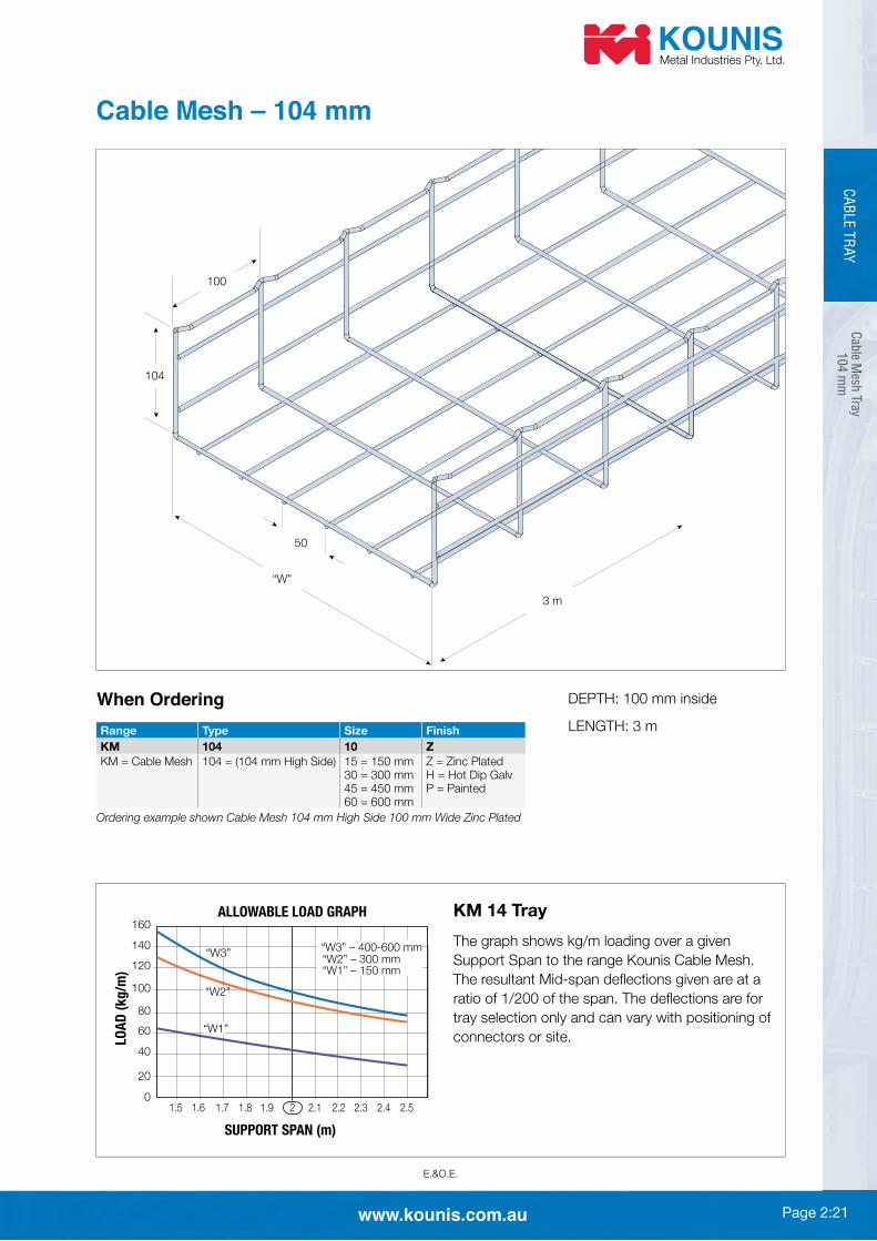
Cable Mesh – 104 mm
104
3 m
100
50
“W”
ALLOWABLE LOAD GRAPH
SUPPORT SPAN (m)
LO
AD
(k
g/m
)
“W3” – 400-600 mm
20
40
60
80
100
120
140
160
0
1.5 1.6 1.7 1.8 1.9 2 2.1 2.2 2.3 2.4 2.5
“W2” – 300 mm
“W1” – 150 mm
“W3”
“W2”
“W1”
KM 14 Tray
Support Span to the range Kounis Cable Mesh.
tray selection only and can vary with positioning of
connectors or site.
When Ordering
Range Type Size Finish
KM 104 10 Z
KM = Cable Mesh Z = Zinc Plated H = Hot Dip Galv P = Painted
Ordering example shown Cable Mesh 104 mm High Side 100 mm Wide Zinc Plated

Page 2:22 www.kounis.com.au
E.&O.E.
CA
BLE T
RAY
Cab
le M
esh T
ray
Acc
esso
ries
& C
onnec
tors
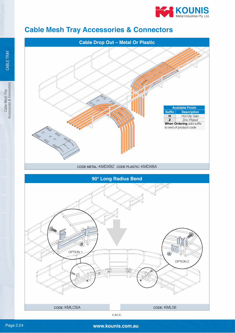
Cable Mesh Tray Accessories & Connectors
CODE:
CODE:
Connector & Bend Assembly
CODE:
Splice Bar Joiner
Tool required for
installation
CODE: KMTOOL
CODE:
Tab Loc Connector
Base Connector
CODE:
Wall Bracket / Box Mounting
Available Finish
!"#$%& Description
H Hot Dip Galv
Z Zinc PlatedWhen Ordering to end of product code

Page 2:23www.kounis.com.au
E.&O.E.
CA
BLE T
RAY
Cab
le Mesh
Tray A
ccessories &
Connecto
rs
Cable Mesh Tray Accessories & Connectors
CODE:
CODE:
Trapeze Bracket 100-600 mm Wide
CODE: KMA09
Slotted Wall Bracket 100-600 mm Wide Overhead Hanger Clip
CODE: KMLDA
Horizontal Adjustment Hold Down Plate
CODE SIZE
500 mm
CODE SIZE
KMA0950 500 mm
CODE: KML05A
Tee Bar Joiner
Available Finish
!"#$%& Description
H Hot Dip Galv
Z Zinc PlatedWhen Ordering to end of product code
Page 2:24 www.kounis.com.au
E.&O.E.
CODE: KMLOSA CODE:
CA
BLE T
RAY
Cab
le M
esh T
ray
Acc
esso
ries
& C
onnec
tors
Cable Mesh Tray Accessories & Connectors
CODE METAL: CODE PLASTIC:
Cable Drop Out – Metal Or Plastic
OPTION 1
OPTION 2
90° Long Radius Bend
Available Finish
!"#$%& Description
H Hot Dip Galv
Z Zinc PlatedWhen Ordering to end of product code
Page 2:25www.kounis.com.au
E.&O.E.
CA
BLE T
RAY
Cab
le Mesh
TrayA
ssembly In
structio
n
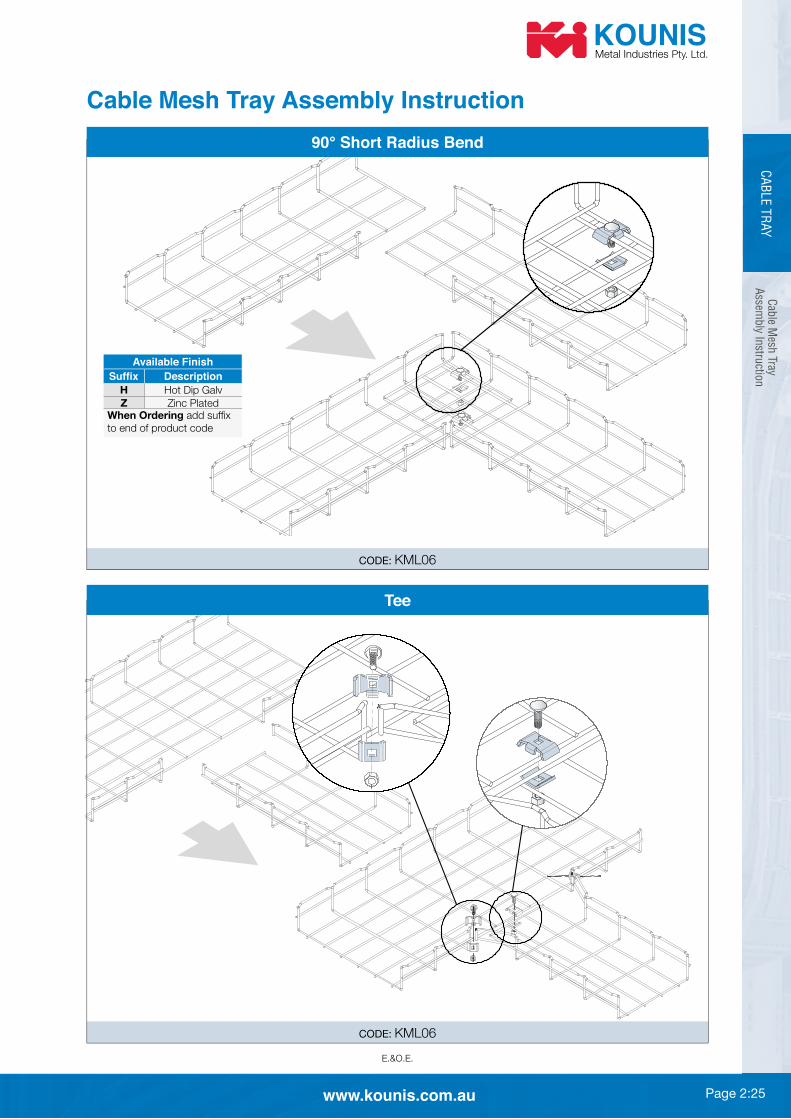
Cable Mesh Tray Assembly Instruction
CODE:
90° Short Radius Bend
CODE:
Tee
Available Finish
!"#$%& Description
H Hot Dip Galv
Z Zinc PlatedWhen Ordering to end of product code

Page 2:26 www.kounis.com.au
E.&O.E.
CODE: CODE:
Cab
le M
esh T
ray
Ass
embly
Inst
ruct
ion
CA
BLE T
RAY
Reducer
Cable Mesh Tray Assembly Instruction
Vertical Inside & Outside Bend
Available Finish
!"#$%& Description
H Hot Dip Galv
Z Zinc PlatedWhen Ordering to end of product code
Page 2:27www.kounis.com.au
E.&O.E.
CA
BLE T
RAY
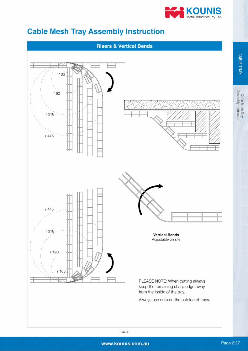
r 445
r 445
r 318
r 318
r 190
r 190
r 163
r 163
Vertical Bends
Adjustable on site
Risers & Vertical Bends
Cab
le Mesh
TrayA
ssembly In
structio
n
Cable Mesh Tray Assembly Instruction
keep the remaining sharp edge away
from the inside of the tray.
Always use nuts on the outside of trays.

Page 2:28 www.kounis.com.au
E.&O.E.
CA
BLE T
RAY
Cab
le M
esh T
ray
Ass
embly
Inst
ruct
ion
90° Bends – Short Radius
WIDTH OF
TRAY
INTERNAL RADIUS
mm
SIZE L x L mm
FIXINGS PER
BEND
WIDTH OF
TRAY
INTERNAL RADIUS
mm
SIZE L x L mm
FIXINGS PER
BEND
WIDTH OF
TRAY
INTERNAL RADIUS
mm
SIZE L x L mm
FIXINGS PER
BEND
WIDTH OF
TRAY
INTERNAL RADIUS
mm
SIZE L x L mm
FIXINGS PER
BEND
WIDTH OF
TRAY
INTERNAL RADIUS
mm
SIZE L x L mm
FIXINGS PER
BEND
WIDTH OF
TRAY
INTERNAL RADIUS
mm
SIZE L x L mm
FIXINGS PER
BEND
WIDTH OF
TRAY
INTERNAL RADIUS
mm
SIZE L x L mm
FIXINGS PER
BEND
Cable Mesh Tray Assembly Instruction

Page 2:29www.kounis.com.au
E.&O.E.
CA
BLE T
RAY
Cab
le Mesh
TrayA
ssembly In
structio
n
90° Bends – Large Radius
WIDTH OF
TRAY
INTERNAL
RADIUS
mm
SIZE
L x L
mm
WIDTH OF
TRAY
INTERNAL
RADIUS
mm
SIZE
L x L
mm
WIDTH OF
TRAY
INTERNAL
RADIUS
mm
SIZE
L x L
mm
WIDTH OF
TRAY
INTERNAL
RADIUS
mm
SIZE
L x L
mm
WIDTH OF
TRAY
INTERNAL
RADIUS
mm
SIZE
L x L
mm
WIDTH OF
TRAY
INTERNAL
RADIUS
mm
SIZE
L x L
mm
WIDTH OF
TRAY
INTERNAL
RADIUS
mm
SIZE
L x L
mm
Cable Mesh Tray Assembly Instruction

Page 2:30 www.kounis.com.au
E.&O.E.
Fire
Rat
ed L
adder
Tra
y S
yste
m –
AS
/NZS
3013
Gen
eral
Des
crip
tion
Fire Rated Ladder Tray System – AS/NZS 3013:2005
General Description
the most cost effective and versatile systems on the market today. Invented and
can be installed in tight ceiling spaces where other products on the market will
simply not fi t.
The foundation of the fi re rated systems is the superior, robustly engineered
specifi cally intended to offer a strong point load with less cross sectional
tray is supplied with custom designed stringers which are fastened to the tray to
fi re rated runs using the standard Kounis Ladder Tray Systems and can be
retro fi tted with the patented support system where fi re rating is required. This
be specifi ed.
System options are:
KT3 Ladder Tray System
!"
!" 50 mm high sided tray
!" Uniform load rating 50 kg per metre
!"
KT5 Ladder Tray System
!"
!" 85 mm high sided tray
!" Uniform load rating 75 kg per metre
!"
Both systems have fi re rated splice plates and trapeze supports used in
!" Must be used as a complete system to achieve fi re rating.
!" Ends of runs must be supported.
CA
BLE T
RAY

Page 2:31www.kounis.com.au
E.&O.E.
CA
BLE T
RAY
Fire Rated
Lad
der Tray
System
KT3 &
KT5
Fire Rated Ladder Tray System – AS/NZS 3013:2005
Fire Rated Ladder Tray KT3
Fire Rated Ladder Tray KT5
Hold Down
Clamp
Splice
Plate
K5500T
'A' = Fixing Ctrs
'B' = O/all
M12 Hex Nut
& Flat Washer
K1064
M12
Allthread
K5500T
Hold Down
Clamp
Splice
Plate
'A' = Fixing Ctrs
'B' = O/all
M12 Nut
& Flat Washer K1064
M12
Allthread
LADDER TRAY WIDTH ‘A’ ‘B’
LADDER TRAY WIDTH ‘A’ ‘B’
When Ordering
Range Type Size Finish
KTFR 3 15 G
G = Galvabond H = Hot Dip Galv
SP = Splice PlateHDC = Hold Down Clamp
Ordering example shown is Ladder Tray Fire Rated 50 mm High Side 150 mm Wide Galvabond

Page 2:32 www.kounis.com.au
E.&O.E.
CA
BLE T
RAY
Notes