11. Pre-excavation Grouting Through Water Bearing … of 14 E C O Toronto, Rapid Excavation and...
14
1 of 14 E C O Toronto, Rapid Excavation and Tunneling Conference, June, 2007 Pre-Excavation Grouting through water bearing zone under high pressure under extreme flow conditions Robert Fu, Engineer 1 , Adam Shang, Engineer 2 , Alex Naudts 3 , M.A.Sc. Civ.Eng. P.Eng. 1.0 ABSTRACT The Yung-Chung-Tunnel in Taiwan, constructed for the Taiwan-East Railway Bureau, collapsed during construction when a water bearing, fractured marble zone was intersected. The inflow was approximately 4,000 liters/second. In spite of 30 relief holes the total inflow into the tunnel remained constant. The pre-excavation grouting through the re-aligned tunnel had to be conducted under extreme flow-conditions. A hot bitumen grouting program was selected for technical and economical reasons out of 13 international proposals. The technical challenges were: • grouting under severe flow conditions • high formation water pressures to be injected with hot bitumen at high temperatures and pressures The hot bitumen grouting program resulted in a dramatic reduction in the hydraulic conductivity and stabilization of the formation and facilitated a problem-free excavation. 2.0 BACKGROUND The New Yung Chung railway tunnel is located in North East Taiwan (Republic Of China), along the line between Suau and Tonau, along the Northern Railway Route in South Ihran prefecture. The tunnel is approximately 4.5km long and is located directly to the west of the older Yung-Le tunnel. The tunnel was excavated from both sides: from the north portal and from the south portal. The main tunnel is approximately 6.5m high and 5m wide. By-pass tunnels or “reconnaissance tunnels”, approximately 4.5m high and 4m wide were excavated, parallel and in advance of the main tunnels, to explore the geology and to obtain information of the problems ahead of the main tunnel. The main tunnel was lined with in-situ cast reinforced concrete. The tunnel was constructed using the drilling and blasting method. The construction of the tunnel was on schedule, until a huge water inflow occurred on 24 October 1998. The back of the tunnel collapsed and the inflow into the tunnel was in the order of 4m 3 /second. This event delayed the project by 3.5 years. By May 2001, more than 50 million m 3 of water had rushed into the tunnel through the breach with no sign of slowing down or decreasing in pressure. The hydrostatic pressure in the drainage holes, intersecting the flow path was exceeding 5 Mpa (750 psi). Rubble filled the tunnel over a length of 300m. 1. Robert Fu, Engineer, Deputy Director, East Railway Improvement Engineering Bureau, Republic of China; 2. Adam Shang, Engineer, President, Jines Construction Co, Ltd., Taipei, Republic of China; 3. Alex Naudts, M.A.Sc. Civ.Eng. P.Eng., President, ECO Grouting Specialists Inc., Grand Valley, Ontario, Canada L0N 1G0
Transcript of 11. Pre-excavation Grouting Through Water Bearing … of 14 E C O Toronto, Rapid Excavation and...

1 of 14
E C O
Toronto, Rapid Excavation and Tunneling Conference, June, 2007
Pre-Excavation Grouting through water bearing zone under high pressure under extreme flow conditions
Robert Fu, Engineer1, Adam Shang, Engineer2, Alex Naudts3, M.A.Sc. Civ.Eng. P.Eng.
1.0 ABSTRACT The Yung-Chung-Tunnel in Taiwan, constructed for the Taiwan-East Railway Bureau, collapsed during construction when a water bearing, fractured marble zone was intersected. The inflow was approximately 4,000 liters/second. In spite of 30 relief holes the total inflow into the tunnel remained constant. The pre-excavation grouting through the re-aligned tunnel had to be conducted under extreme flow-conditions. A hot bitumen grouting program was selected for technical and economical reasons out of 13 international proposals. The technical challenges were:
• grouting under severe flow conditions • high formation water pressures to be injected with hot bitumen at high temperatures and
pressures The hot bitumen grouting program resulted in a dramatic reduction in the hydraulic conductivity and stabilization of the formation and facilitated a problem-free excavation. 2.0 BACKGROUND The New Yung Chung railway tunnel is located in North East Taiwan (Republic Of China), along the line between Suau and Tonau, along the Northern Railway Route in South Ihran prefecture. The tunnel is approximately 4.5km long and is located directly to the west of the older Yung-Le tunnel. The tunnel was excavated from both sides: from the north portal and from the south portal. The main tunnel is approximately 6.5m high and 5m wide. By-pass tunnels or “reconnaissance tunnels”, approximately 4.5m high and 4m wide were excavated, parallel and in advance of the main tunnels, to explore the geology and to obtain information of the problems ahead of the main tunnel. The main tunnel was lined with in-situ cast reinforced concrete. The tunnel was constructed using the drilling and blasting method. The construction of the tunnel was on schedule, until a huge water inflow occurred on 24 October 1998. The back of the tunnel collapsed and the inflow into the tunnel was in the order of 4m3/second. This event delayed the project by 3.5 years. By May 2001, more than 50 million m3 of water had rushed into the tunnel through the breach with no sign of slowing down or decreasing in pressure. The hydrostatic pressure in the drainage holes, intersecting the flow path was exceeding 5 Mpa (750 psi). Rubble filled the tunnel over a length of 300m. 1. Robert Fu, Engineer, Deputy Director, East Railway Improvement Engineering Bureau, Republic of China; 2. Adam Shang, Engineer, President, Jines Construction Co, Ltd., Taipei, Republic of China; 3. Alex Naudts, M.A.Sc. Civ.Eng. P.Eng., President, ECO Grouting Specialists Inc., Grand Valley, Ontario, Canada L0N 1G0
2 of 14
E C O
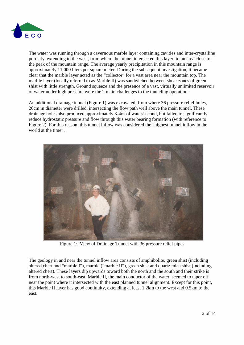
The water was running through a cavernous marble layer containing cavities and inter-crystalline porosity, extending to the west, from where the tunnel intersected this layer, to an area close to the peak of the mountain range. The average yearly precipitation in this mountain range is approximately 11,000 liters per square meter. During the subsequent investigation, it became clear that the marble layer acted as the “collector” for a vast area near the mountain top. The marble layer (locally referred to as Marble II) was sandwiched between shear zones of green shist with little strength. Ground squeeze and the presence of a vast, virtually unlimited reservoir of water under high pressure were the 2 main challenges to the tunneling operation. An additional drainage tunnel (Figure 1) was excavated, from where 36 pressure relief holes, 20cm in diameter were drilled, intersecting the flow path well above the main tunnel. These drainage holes also produced approximately 3-4m3of water/second, but failed to significantly reduce hydrostatic pressure and flow through this water bearing formation (with reference to Figure 2). For this reason, this tunnel inflow was considered the “highest tunnel inflow in the world at the time”.
Figure 1: View of Drainage Tunnel with 36 pressure relief pipes
The geology in and near the tunnel inflow area consists of amphibolite, green shist (including altered chert and “marble I”), marble (“marble II”), green shist and quartz mica shist (including altered chert). These layers dip upwards toward both the north and the south and their strike is from north-west to south-east. Marble II, the main conductor of the water, seemed to taper off near the point where it intersected with the east planned tunnel alignment. Except for this point, this Marble II layer has good continuity, extending at least 1.2km to the west and 0.5km to the east.

3 of 14
E C O
Figure 2: Conceptual view of the water bearing mechanism of the New Yung Chung Tunnel
The maximum thickness of the water bearing formation is 70m. Two major joints, which cross at right angles with each other are developed in the marble layers. One is running parallel with the shist and has been noticed in several outcrops, some near a cliff where it caused secondary breakage and at some spots forming porous coarse breccia. Along the already weakened line of joints and shistosity are ant-nest like, small leaching channels which are often filled with fine gouge or fine gravel. A lot of this infill material washed into the tunnel. In order to complete the New Yung Chung tunnel, it was partly re-aligned and the north and the south faces were advanced to approximately 50m from the water bearing marble zone, which was approximately 20m thick, where the new tunnel alignment was going to intersect the water bearing zone. For the lay-out of the planned and existing tunnels, refer to Figure 3. Since dewatering the formation was not working, the Taiwanese Railway Authority, assisted by an international panel of consultants, invited technical proposals from all over the globe, to construct a structural grout curtain, to be installed under flow conditions and under a hydrostatic pressure of 5 Mpa, that would facilitate safe tunneling through the water bearing area. The technical proposal submitted by Jines Construction from Taipei, Taiwan, assisted by ECO Grouting Specialists Ltd from Canada was selected from 12 other international proposals. The selection was based on technical merit, proven experience in this type of work and cost. The Jines group was also the only bidder who was offering a fixed budget price to perform this challenging pre-excavation grouting work and who guaranteed a successful outcome. The remedial grouting job was awarded to Jines in November 2001 and construction of the grout curtain started in February 2002.
Drainage Tunnel
Groundwater level Before the major inflow
Discontinuity caused
by fault, etc.
Eastern Reconnaissance
Tunnel
Existing tunnel (Old Yung Le Tunnel)
Main Tunnel
Groundwater Level after the inflow
6 Mpa
5 Mpa 2.
5 M

4 of 14
E C O
Figure 3: Re-alignment of tunnels at the time of the grouting early 2002
3.0 OVERVIEW OF THE PROPOSED GROUTING METHOD TO FACILITATE A
SAFE TUNNELING OPERATION THROUGH THE WEAK WATER BEARING ZONE
A plan to facilitate safe excavation for both the reconnaissance and the main tunnels were tabled. It involved the installation of a series of heavy duty steel sleeve pipes, to be grouted with hot bitumen. The steel sleeve pipes were acting as grout delivery pipes and as a forespiling system. The plan proposed by the Jines team was serving 2 purposes:
- minimize the inflow of water into the new tunnel, in the water bearing zone when tunneling through it
- provide the necessary mechanical strength to the formation to minimize or prevent ground squeeze
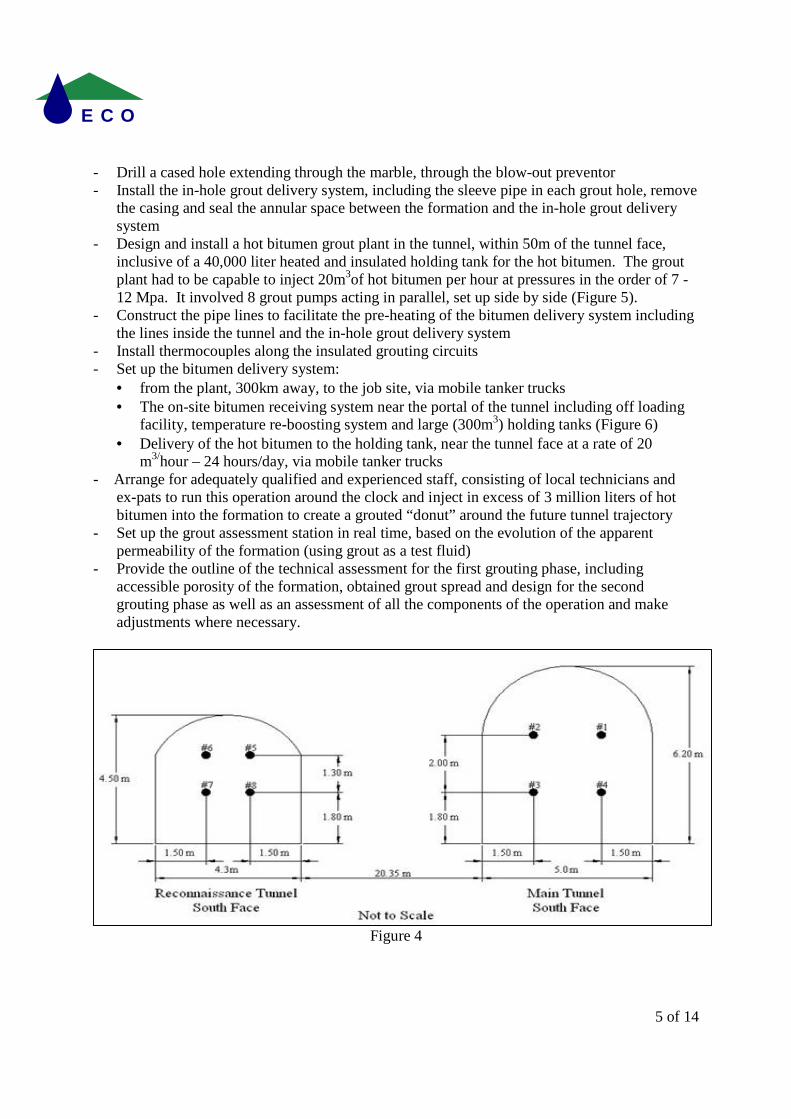
It was envisioned that the grouting project would consist of 2, potentially 3 grouting phases. Contrary to what is commonly done in bitumen grouting projects, all grouting was to be performed with bitumen (no cement grouting). Phase I involved the following tasks and activities: - Drill 8 cased holes (the primary grout holes) for the installation of the steel sleeve pipes: 4
per tunnel (refer to Figure 4) - Perform the drilling and grouting activities from the south side, where a lot of space was
available to accommodate this work - Start the holes by installing heavy duty steel standpipes, grouted in place and tested to a
pressure of 15 Mpa; attach a blow-out-preventor on each stand pipe, prior to drilling into the marble zone
5 of 14
E C O
- Drill a cased hole extending through the marble, through the blow-out preventor - Install the in-hole grout delivery system, including the sleeve pipe in each grout hole, remove
the casing and seal the annular space between the formation and the in-hole grout delivery system
- Design and install a hot bitumen grout plant in the tunnel, within 50m of the tunnel face, inclusive of a 40,000 liter heated and insulated holding tank for the hot bitumen. The grout plant had to be capable to inject 20m3of hot bitumen per hour at pressures in the order of 7 - 12 Mpa. It involved 8 grout pumps acting in parallel, set up side by side (Figure 5).
- Construct the pipe lines to facilitate the pre-heating of the bitumen delivery system including the lines inside the tunnel and the in-hole grout delivery system
- Install thermocouples along the insulated grouting circuits - Set up the bitumen delivery system:
• from the plant, 300km away, to the job site, via mobile tanker trucks • The on-site bitumen receiving system near the portal of the tunnel including off loading
facility, temperature re-boosting system and large (300m3) holding tanks (Figure 6) • Delivery of the hot bitumen to the holding tank, near the tunnel face at a rate of 20
m3/hour – 24 hours/day, via mobile tanker trucks - Arrange for adequately qualified and experienced staff, consisting of local technicians and
ex-pats to run this operation around the clock and inject in excess of 3 million liters of hot bitumen into the formation to create a grouted “donut” around the future tunnel trajectory
- Set up the grout assessment station in real time, based on the evolution of the apparent permeability of the formation (using grout as a test fluid)
- Provide the outline of the technical assessment for the first grouting phase, including accessible porosity of the formation, obtained grout spread and design for the second grouting phase as well as an assessment of all the components of the operation and make adjustments where necessary.
Figure 4

6 of 14
E C O
Figure 5: Grout plant in foreground, insulated bitumen holding tank in background
Figure 6: Off Loading Facility and insulated Bitumen holding tanks outside tunnel

7 of 14
E C O
Phase II was to involve the following tasks and activities: - Install 8 secondary grout holes, outfitted with the requisite in-hole grout delivery systems - Perform the hot bitumen grouting - Evaluate the results Phase III (if necessary) was to drill and grout additional holes to ensure the future tunnel was completely protected by the grout curtain, having a thickness of at least one tunnel diameter. 4.0 HISTORY OF HOT BITUMEN GROUTING By the end of the 19th century, grouting with hot bitumen for remedial repair work on dams and seepage control in rock tunnels was introduced. Bitumen was first used at European dams in Switzerland and France and later at dam sites in North America. There is documented evidence in the records of Puget Sound Power and Light that hot bitumen was used during the 1920’s at Lower Baker Dam near Seattle, and on some dam grouting projects for the Tennessee Valley Authority (U.S.A). The development of different types of environmentally friendly bitumen expanded its use in the grouting industry. Oxidized blown bitumen replaced the softer bitumen (typically used in road paving applications) and emulsions in grouting, and played an important role in marine, civil and mining applications, mainly for seepage control or prevention. The use of hot bitumen was “rediscovered” during the early 1980’s with the success of the Lower Baker Dam (USA) and the Stewartville Dam (Canada) grouting projects. Hot bitumen grouting made a remarkable comeback during the late 1990’s. Projects in the Philippines, Brazil, Eastern Europe, New Brunswick (Canada), West Virginia (USA), and Wisconsin (USA) demonstrated that the application of bitumen technology is an efficient, economical and powerful tool to prevent or stop seepage and major leaks (Ref.2, Schonian, E. & A. Naudts, 2003). The nature of most bitumen grouting projects typically involved emergency situations in which very serious water inflow problems needed to be solved. This has actually hampered the exposure of bitumen grouting in the mining and civil engineering world, since clients often do not wish that detailed information be disseminated on their misfortune or problem situation. 5.0 HOW HOT BITUMEN GROUTING WORKS Dr. Erich Schonian, one of the first scientists to study the penetrability and behavior of hot bitumen, documented remarkable findings regarding bitumen penetration in cracks (Ref. 3, Schonian, E., 1999). As the bitumen comes in contact with water, the viscosity of the grout increases rapidly, resulting in a lava-like flow. A hard insulating crust is readily formed at the interface between water and bitumen and shelters the low viscosity, hot bitumen behind it. The “crust” or “skin” is re-melted from within when hot bitumen continues to be injected. When hot bitumen is injected into a medium with running water, it cools quickly at the interface with water. Steam is created at that point, decreasing the viscosity of the bitumen. The steam acts as an “air lift” drawing the bitumen into its pathway through small and large fissures or pore channels. The centre of the bitumen mass remains hot, and, as a result of the grouting pressure,
8 of 14
E C O
continuously breaks through (re-melting) the skin formed at the interface of the bitumen and water. The faster the water flows, the faster the bitumen cools off. The skin prevents wash-out while the “sheltered” hot bitumen behind the skin behaves as a Newtonian fluid, penetrating in a similar fashion as solution grouts. Because bitumen has good insulating characteristics, it can be injected for a very long time (days – even weeks) into the same grout hole without the risk of either premature blockage or wash-out. The width of the fissures accessible to hot bitumen depends on the duration of the grouting operation. The longer the grouting operation, the finer the apertures the bitumen will penetrate. Hot bitumen will penetrate fractures as small as 0.1mm as demonstrated during the Kraghammer Project in 1963. When hot bitumen cools it is subject to significant thermal shrinkage. This phenomenon is partially overcome in smaller fractures if pressure continues to be applied and warmer bitumen pushes the cooling bitumen into the shrinkage gaps. Cement based suspension grout is often injected in conjunction with hot bitumen to compensate for the thermal shrinkage of the bitumen; to make the bitumen less susceptible to creep; and to increase the mechanical strength of the end product. 6.0 SPECIAL CONSIDERATIONS FOR USING HOT BITUMEN GROUTING The equipment and set-up are generally more complex for bitumen grouting than for the applications involving regular cement based grouts or solution grouts. The operating temperature of the surface pipe system needs to be in the range of 180 – 225 degrees Celsius (356 – 437 degrees Fahrenheit). Moreover, a supply of hot bitumen needs to be obtained and maintained at the requisite temperature. The bitumen should, ideally, be delivered to the site in heated and insulated bulk takers with the potential to boost or adjust the temperature on site in a custom build grout plant. The piping system used during grouting to deliver the hot bitumen from the bitumen pumps to the sleeve pipe “stinger” located at the end of the bitumen grout hole, must either be pre-heated with hot oil, heat trace, or steam, potentially through a re-circulation system. Additionally, the grout pipes must be insulated and equipped with temperature sensors and pressure gauges. The flow rate, total volume of grout injected, and grouting pressure must be monitored and recorded in real-time. This allows informed decisions to be made while the operation is in progress. The apparent Lugeon value is the permeability coefficient of the formation using grout as a test fluid (Ref. 5, Landry, E., Lees & Naudts, 2000). It is noteworthy that during the execution of a hot bitumen grouting program the apparent Lugeon value typically increases with time (contrary to cement grouting operations) due to the excellent penetration properties of the bitumen into the formation (which is warming up). 7.0 ENVIRONMENTAL ISSUES The type for use in grouting is a “hard”, oxidized, environmentally friendly type of bitumen with a high solidification point. Oxidized blown bitumen has a long history of successful use for lining (potable) water reservoirs in California (over 40 years) and in 1987 Washington and Oregon State wildlife authorities have used it for lining fish hatchery ponds.
9 of 14
E C O
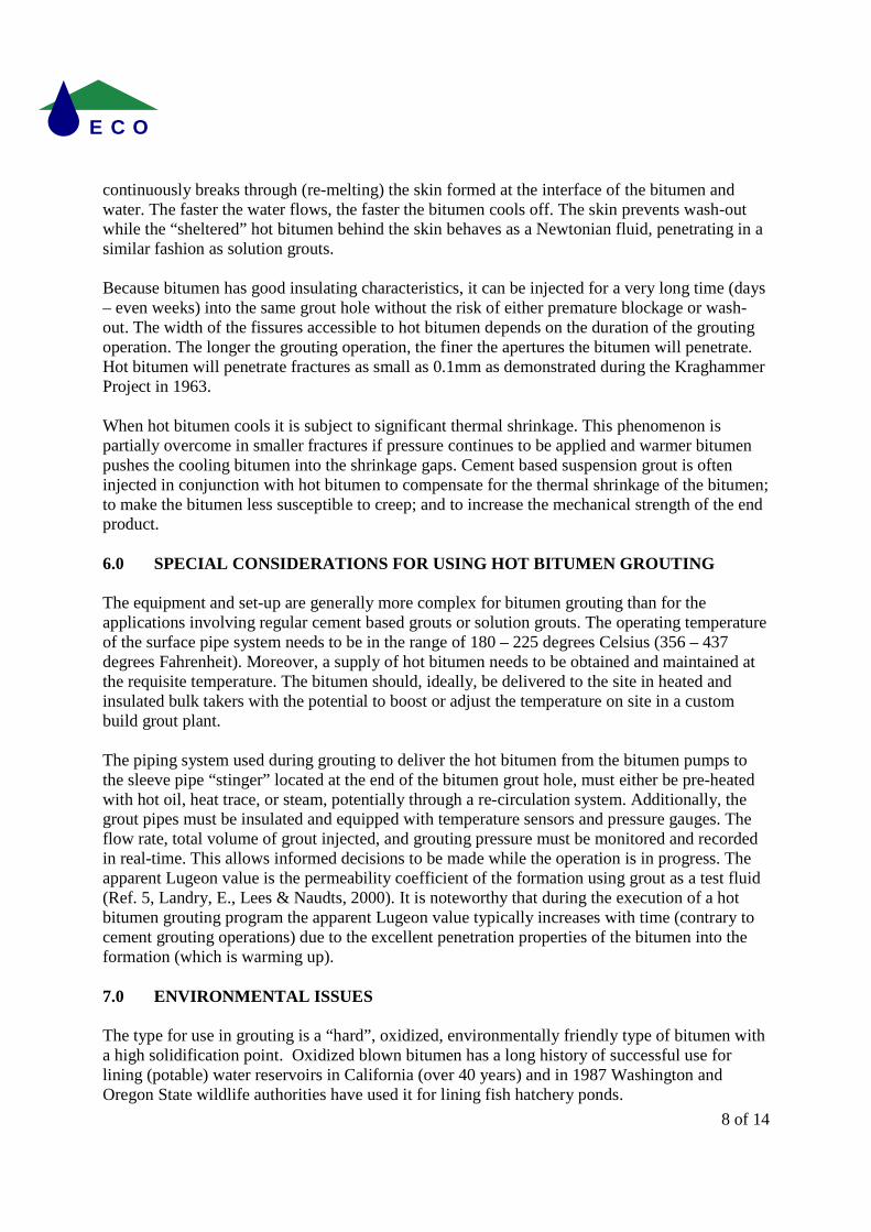
Oxidized bitumen has proven to be in compliance with American Water Works Association (AWWA) standards for leachate resistance of materials for use in potable water applications. Indeed, it is now routinely used for water pipeline lining applications. It could be considered the most environmentally friendly grout presently available on the market. 8.0 THE ACTUAL GROUTING OPERATION AT THE NEW YUNG CHUNG TUNNELS The actual grouting work turned out to be a very challenging undertaking. Many setbacks had to be overcome. The first grouting phase took place in late February 2002 and the third grouting phase was completed by mid May 2002. The drilling of the cased holes for the installation of the in-hole grout delivery system –including the sleeve pipe – was not an easy undertaking (Figure 7). In each hole, as soon as the marble zone was intersected, “all hell broke loose” and water inflows of more than a hundred liters/second under pressure of 5 Mpa gushed into the hole. Based on the outflow, the average permeability of the water baring marble formation was approximately 120-150 Lugeon (0.0013 – 0.0016 cm/s). All 8 primary holes were extended -albeit with great difficulty – to the far end of the marble zone. The in-hole grout delivery system consisted of 3 concentric heavy duty steel pipes (to facilitate pre-heating of the in-hole grout delivery system) ending into a sleeve pipe, located in the marble zone. Barrier bags were inflated with cement based grout around the in-hole grout delivery pipe and any residual seepage around these pipes was sealed using water reactive, hydrophobic polyurethane grout.
Figure 7:
10 of 14
E C O
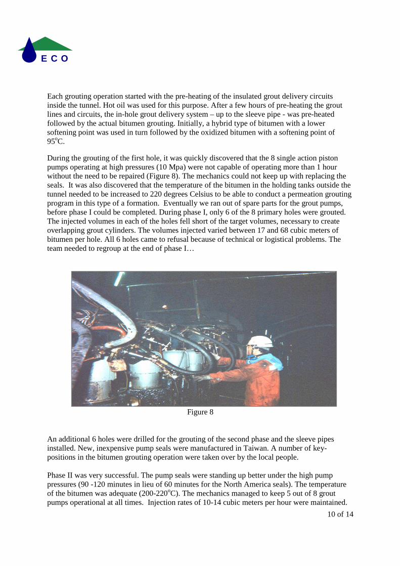
Each grouting operation started with the pre-heating of the insulated grout delivery circuits inside the tunnel. Hot oil was used for this purpose. After a few hours of pre-heating the grout lines and circuits, the in-hole grout delivery system – up to the sleeve pipe - was pre-heated followed by the actual bitumen grouting. Initially, a hybrid type of bitumen with a lower softening point was used in turn followed by the oxidized bitumen with a softening point of 95oC. During the grouting of the first hole, it was quickly discovered that the 8 single action piston pumps operating at high pressures (10 Mpa) were not capable of operating more than 1 hour without the need to be repaired (Figure 8). The mechanics could not keep up with replacing the seals. It was also discovered that the temperature of the bitumen in the holding tanks outside the tunnel needed to be increased to 220 degrees Celsius to be able to conduct a permeation grouting program in this type of a formation. Eventually we ran out of spare parts for the grout pumps, before phase I could be completed. During phase I, only 6 of the 8 primary holes were grouted. The injected volumes in each of the holes fell short of the target volumes, necessary to create overlapping grout cylinders. The volumes injected varied between 17 and 68 cubic meters of bitumen per hole. All 6 holes came to refusal because of technical or logistical problems. The team needed to regroup at the end of phase I…
Figure 8
An additional 6 holes were drilled for the grouting of the second phase and the sleeve pipes installed. New, inexpensive pump seals were manufactured in Taiwan. A number of key-positions in the bitumen grouting operation were taken over by the local people. Phase II was very successful. The pump seals were standing up better under the high pump pressures (90 -120 minutes in lieu of 60 minutes for the North America seals). The temperature of the bitumen was adequate (200-220oC). The mechanics managed to keep 5 out of 8 grout pumps operational at all times. Injection rates of 10-14 cubic meters per hour were maintained.
11 of 14
E C O
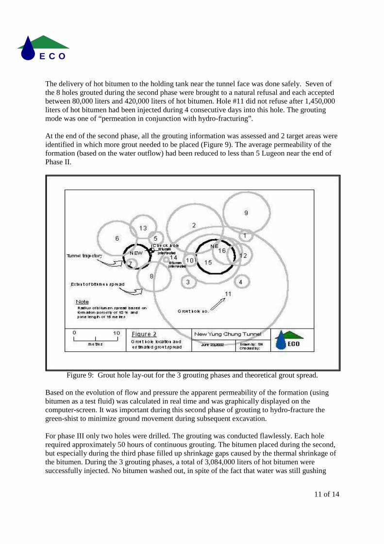
The delivery of hot bitumen to the holding tank near the tunnel face was done safely. Seven of the 8 holes grouted during the second phase were brought to a natural refusal and each accepted between 80,000 liters and 420,000 liters of hot bitumen. Hole #11 did not refuse after 1,450,000 liters of hot bitumen had been injected during 4 consecutive days into this hole. The grouting mode was one of “permeation in conjunction with hydro-fracturing”. At the end of the second phase, all the grouting information was assessed and 2 target areas were identified in which more grout needed to be placed (Figure 9). The average permeability of the formation (based on the water outflow) had been reduced to less than 5 Lugeon near the end of Phase II.
Figure 9: Grout hole lay-out for the 3 grouting phases and theoretical grout spread.
Based on the evolution of flow and pressure the apparent permeability of the formation (using bitumen as a test fluid) was calculated in real time and was graphically displayed on the computer-screen. It was important during this second phase of grouting to hydro-fracture the green-shist to minimize ground movement during subsequent excavation. For phase III only two holes were drilled. The grouting was conducted flawlessly. Each hole required approximately 50 hours of continuous grouting. The bitumen placed during the second, but especially during the third phase filled up shrinkage gaps caused by the thermal shrinkage of the bitumen. During the 3 grouting phases, a total of 3,084,000 liters of hot bitumen were successfully injected. No bitumen washed out, in spite of the fact that water was still gushing
12 of 14
E C O
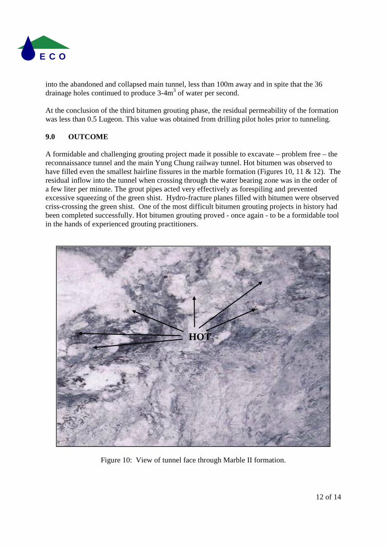
into the abandoned and collapsed main tunnel, less than 100m away and in spite that the 36 drainage holes continued to produce 3-4m3 of water per second. At the conclusion of the third bitumen grouting phase, the residual permeability of the formation was less than 0.5 Lugeon. This value was obtained from drilling pilot holes prior to tunneling. 9.0 OUTCOME A formidable and challenging grouting project made it possible to excavate – problem free – the reconnaissance tunnel and the main Yung Chung railway tunnel. Hot bitumen was observed to have filled even the smallest hairline fissures in the marble formation (Figures 10, 11 & 12). The residual inflow into the tunnel when crossing through the water bearing zone was in the order of a few liter per minute. The grout pipes acted very effectively as forespiling and prevented excessive squeezing of the green shist. Hydro-fracture planes filled with bitumen were observed criss-crossing the green shist. One of the most difficult bitumen grouting projects in history had been completed successfully. Hot bitumen grouting proved - once again - to be a formidable tool in the hands of experienced grouting practitioners.
Figure 10: View of tunnel face through Marble II formation.
HOT BITUMEN

13 of 14
E C O
Figure 11: Tunnel face entering the water-bearing grouted zone
Figure 12: Sample of marble impregnated with Hot Bitumen

14 of 14
E C O
10.0 ACKNOWLEDGEMENT The authors like to thank the staff of the East Railway Improvement Engineering Bureau, Republic of China, Jines Construction Co, Ltd., Taipei, Republic of China; and ECO Grouting Specialists Inc. for their tremendous effort and dedication to bring one of the most challenging grouting projects ever undertaken, to a successful conclusion.
References Reference 1. Van Asbeck, W.F. & E. Schonian, Bitumen in Wasserbau, Band 2 (Bitumen in Hydraulic Engineering, Vol 2). Huthig und Dreyer, Heidelberg, and Deutsche Shell AG, Hamburg 1968, pp. 323-326. Reference 2. Schonian, E. & A. Naudts, Hot Bitumen Grouting – Rediscovered, Bitumen, Heft 3 & Heft 4, Fall and Winter, 2003, pp. 118-123, 178-183. Reference 3. Schonian, E., The Shell Bitumen Hydraulic Engineering Handbook and CD (more text and Figures/Photos). Shell International Petroleum Company Ltd., London 1999 Reference 4. Naudts, A & S. Hooey, Hot Bitumen Grouting: The antidote for catastrophic inflows, ASCE Conference, Grouting and Ground Treatment, Proceedings of the Third International Conference, New Orleans, 2003,Vol.2, pp.1293-1304. Reverence 5. Landry, E., D. Lees & A. Naudts, Dew Developments in Rock and Soil Grouting: Design and Evaluation, Geotechnical News, Richmond, British Columbia, September 2000 pp, 38-44