Compensation Grouting: Limiting settlements of two railway ... · The basic principle of...
13
Ground Improvement Techniques 1 Presented by Keller Grundbau GesmbH Mariahilfer Straße 127a A-1150 Wien Tel. +43 1 8923526 Fax +43 1 8923711 E-mail: [email protected] www.KellerGrundbau.at C C o o m m p p e e n n s s a a t t i i o o n n g g r r o o u u t t i i n n g g f f o o r r l l i i m m i i t t i i n n g g s s e e t t t t l l e e m m e e n n t t s s o o f f t t w w o o r r a a i i l l w w a a y y b b r r i i d d g g e e s s i i n n d d u u c c e e d d b b y y a a t t w w i i n n - - t t u u n n n n e e l l e e x x c c a a v v a a t t i i o o n n C. Kummerer, R. Thurner Keller Grundbau GesmbH, Söding, Austria A. Rigazio, A. Zamagni Trevi Spa, Cesena, Italy XIV. European Conference on Soil Mechanics and Geotechnical Engineering, Madrid, Spain, September 24.-29.2007 Technical paper 61-65 E
Transcript of Compensation Grouting: Limiting settlements of two railway ... · The basic principle of...
Ground Improvement Techniques
1
Presented by Keller Grundbau GesmbH Mariahilfer Straße 127a A-1150 Wien Tel. +43 1 8923526 Fax +43 1 8923711 E-mail: [email protected] www.KellerGrundbau.at
CCoommppeennssaattiioonn ggrroouuttiinngg ffoorr lliimmiittiinngg sseettttlleemmeennttss ooff ttwwoo rraaiillwwaayy bbrriiddggeess iinndduucceedd bbyy aa ttwwiinn--ttuunnnneell eexxccaavvaattiioonn
CC.. KKuummmmeerreerr,, RR.. TThhuurrnneerr KKeelllleerr GGrruunnddbbaauu GGeessmmbbHH,, SSööddiinngg,, AAuussttrriiaa AA.. RRiiggaazziioo,, AA.. ZZaammaaggnnii TTrreevvii SSppaa,, CCeesseennaa,, IIttaallyy XXIIVV.. EEuurrooppeeaann CCoonnffeerreennccee oonn SSooiill MMeecchhaanniiccss aanndd GGeeootteecchhnniiccaall EEnnggiinneeeerriinngg,, MMaaddrriidd,, SSppaaiinn,, SSeepptteemmbbeerr 2244..--2299..22000077 TTeecchhnniiccaall ppaappeerr 6611--6655 EE
Compensation grouting for limiting settlements of two railway bridges induced
by a twin-tunnel excavation Compensation Grouting pour limiter et compenser les tassements sous un pont
ferroviaire pendant le percement de deux tunnels
C. Kummerer, R. Thurner Keller Grundbau GesmbH, Söding, Austria
A. Rigazio, A. Zamagni Trevi Spa, Cesena, Italy
ABSTRACT For the construction of the high speed railway line Rome-Milan, tunnelling operation took place directly under-neath the alignment of the existing railway line in the city centre of Bologna. To minimize the effects of the tunnel excavation countermeasures were implemented for the protection of two railway bridges. The twin-tunnel excava-tion underneath these historical railway bridges was performed utilizing the Compensation Grouting technique in order to limit the effects of (differential) settlements induced on the bridges. The tunnelling was made with two 9.4 m diameter EPB-shield machines with a cover of about 20 m. The excava-tion was performed in very heterogeneous alluvial strata. In the first part of the alignment the tunnels were exca-vated in sea clay and loose sandy deposit below the water level, in the in the second part it consisted of Savena river deposits with mainly gravel and sand strata, locally with a high percentage of fines (lenses of clay and silt). The groundwater level was found underneath the tunnel excavation. Compensation grouting was seen as the only measure to control and limit the deformations. For the grouting op-erations, two arrays of grouting pipes were installed by means of Horizontal Directional Drilling technique. With these curved drillings the pre-treatment of the ground and the consequent lifting of the structures were per-formed. All the activities were monitored with a hydraulic liquid levelling system. To prove the feasibility of the Compensation grouting concept, a real-scale field test was conducted prior to the grouting operation. Details of this compensation grouting work are presented in this paper. RÉSUMÉ La construction de la ligne ferroviaire à grande vitesse entre Rome et Milan a demandé l’exécution d’un tunnel au dessous d’une ancienne ligne ferroviaire située au centre de la ville de Boulogne. Pourtant des contre-mesures im-portantes ont été prises à fin que les effets du percement du tunnel fussent limités au maximum sous le pont fer-roviaire qui déjà existe. La technique du "Compensation Grouting" a bien permis de limiter et compenser les tas-sements différentiels produits du percement des deux tunnels au dessous des fondations en briques du pont ferroviaire qui déjà existe. Les deux tunnels ont été construits avec un diamètre de 9,4 mètres environ à travers une machine de percement EPB-Shield (Earth Pressure Balanced), sous une couverture de 20 mètres environ de terrain. Le percement a été fait sur des terrains d’origine alluviale, caractérisée des stratifications hétérogènes. La première partie du tunnel a été percée dans des terrains constitués des argiles marines et dans des dépôts de sable défaite au dessous du ni-veau de la nappe d’eau. La zone, qui est l’objet de cet article, est constituée pour la plupart des sables et des gra-viers stratifiés (typique du fleuve Savena qui passe aux alentours) où se trouvent des zones constituées des terrains qui contiennent du matériel fin (argile et limon). Dans cette zone le niveau de la nappe d’eau était placé sous les tunnels. Le "Compensation Grouting" a été considéré le seul système pour contrôler et limiter en même temps les déformations. Les opérations d’injection ont été conduites grâce à l’intervention de certaines cannes à manchette qui ont été installées à travers une technique, tout à fait particulière, de forage horizontale guidée, qui a permis de faire des perforations curvilignes, nécessaires pour l’exécution des injections d’avant consolidation et soulèvement du pont ferroviaire. Chaque activité faite a été contrôlée avec un système des tasses hydrauliques du dénivelle-ment. Keywords: settlements, tunnelling, compensation grouting, directional drilling, monitoring
Compensation Grouting for limiting settlements
2
1 PROBLEM STATEMENT Important infrastructure works are actually under progress in Italy for the realization of efficient inter-nodal railway links. As part of the high speed railway line Rome – Milan the railway works in Bologna are among the most challenging ones as beside of the construction of the new Cen-tral railway station of Bologna the city itself has to be under passed. As in all inner-city areas the construction of new infrastructure is accompanied by an impact to habitants and existing structures. To minimize these problems designers try to choose an align-ment with a limited number of interferences. Especially if private ground has to be occupied for temporary or permanent construction purposes severe problems arise. To overcome this, the alignment is mostly realized under public ground. Consequently the tunnel alignment was planned directly under the existing line because the tunnel excavation could be performed on public ground. Along the present high-speed line a number of structures were effected by the tunnel excava-tion of which three major railway bridges were identified as the most critical ones with respect to settlements. A series of protective measures are utilized in civil engineering projects to deal with settlements induced by tunnelling (Harris 2001). For the protection of the most important structures basi-cally grouting treatment was considered in this project as the most effective measure, either as pre-treatment with grouting for consolidating the ground or as an active settlement control with compensation grouting. Compensation grouting was successfully utilized in other infra-structure projects for limiting settlements of sensitive structures (see e.g. Schweiger and Falk 1998, Chambosse and Otterbein 2001). 2 TUNNELLING PROJECT “SAN RUFFILLO” BOLOGNA Two EPB-tunnel boring machines excavated two single track tunnels with 9.4 m in diameter from July 2003 to April 2006. The tunnel excavation with approximately 7 km length mainly runs below the existing Florence-Bologna railway embankment, starting from the south of the city up to the city centre. The project “San Ruffillo – lotto5” begins at the North abutment pier of the Savena bridge (km.0+000) and ends at the new Central station (km.7+375). An overview of the complete pro-ject is depicted in Figure 1. The excavation was realized in very heterogeneous alluvial strata. In the first part of the align-ment, the tunnels are excavated in sea clay and loose sandy deposits (Pliocenic Clay and Yellow Pleistocenic Sands) below the water level. In the zone of the compensation grouting works the subsoil consisted of deposits of the Savena River. This mainly gravely and sandy soil locally had a high percentage of fines (lenses of clay and silt). In the section of compensation grouting the groundwater level was below ground surface. The heterogeneity of the ground and the changing groundwater conditions were a critical aspect because the excavation conditions in terms of surface settlement response and machines’ behav-iour changed very rapidly.

C. Kummerer, R. Thurner, Keller Grundbau GesmbH; A. Rigazio, A. Zamagni, Trevi Spa
3
Figure 1. Project overview 3 DESIGN OF COMPENSATION GROUTING FOR TWO RAILWAY BRIDGES The basic principle of compensation grouting is the reduction or elimination of settlements dur-ing the excavation and, if necessary, during the following observation phase (Mair 1994). There-fore grouting pipes (Tubes a Manchettes, TAMs) have to be installed in the ground between the structures and the excavation. Settlements have to be monitored periodically and evaluated for controlling the grouting operation (Falk 2004). The phases of compensation grouting are : • Installation of a measurement system • Implementation of grouting pipes • Pre-treatment of the ground to obtain immediate response of grouting for the tunnel excava-
tion phase • Concurrent grouting during the tunnel excavation (if necessary, additional grouting after the
excavation to compensate settlements during the observation phase). At the preliminary stage of this project shafts were considered for drilling the TAM array. But it turned out that the excavation of the shafts was not possible because of difficulties with the use of private ground and buried service lines. Therefore an alternative solution was found with the

Compensation Grouting for limiting settlements
4
Horizontal Directional Drilling Technique (HDD). The advantage of HDD was that all the drill-ings for the implementation of the grouting pipes were realized from an accessible adjacent par-cel. A field test had to be performed before the start of the compensation grouting operation in or-der to confirm the feasibility. The objectives were to evaluate: • the reliability and precision of the measurement system, • the application of the HDD technology for the installation of long and curved grouting pipes • and the controlled heaving of bridge piers under the given soil and load conditions. As key parameter the grout efficiency - the ratio of volume which effectively is obtained at ground surface and the grout volume - was obtained. This value is important because it deter-mines the grouting work. During the design phase the allowable deformation state was studied. The designers of the Ital-ian railways paid special attention to differential settlements between adjacent piers of the bridge as these differential movements were considered as the more critical ones. Three differ-ent limit states were considered (see Table 1). • Limit state 1: compensation grouting to bring differential settlements to allowable values • Limit state 2: compensation grouting to bring differential settlements to allowable values, with evaluation of reducing the TBM advance • Limit state 3: Interruption of train traffic and additional corrective measures Table 1: Limit state for the compensation grouting programme (L…effective width of the arch) Limit state 1 Limit state 2 Limit state 3 L / 4000 L / 3000 L / 1000 (mm) (mm) (mm)
Bridge “Ponte Via Emilia levante”
L=8.1 m 2.0 2.7 8.1
L=16.0 m 4.0 5.3 16.0
Bridge “Ponte Via Rimesse”
L=7.2 m 1.8 2.3 7.2
L=14.4 m 3.6 4.8 14.4
Below Limit state 1 the compensation grouting strategy was chosen by the contractor on basis of the measured (differential) settlements. Exceeding Limit state 1 a group of engineers of the client, the general contractor and the grouting specialist would have to choose the grouting strategy. Exceeding limit state 2 would have influenced also the train traffic. As a consequence the differential settlements had to be kept below Limit state 1 in order to avoid any effect on the tunnel excavation and the train traffic on the existing line.
C. Kummerer, R. Thurner, Keller Grundbau GesmbH; A. Rigazio, A. Zamagni, Trevi Spa
5
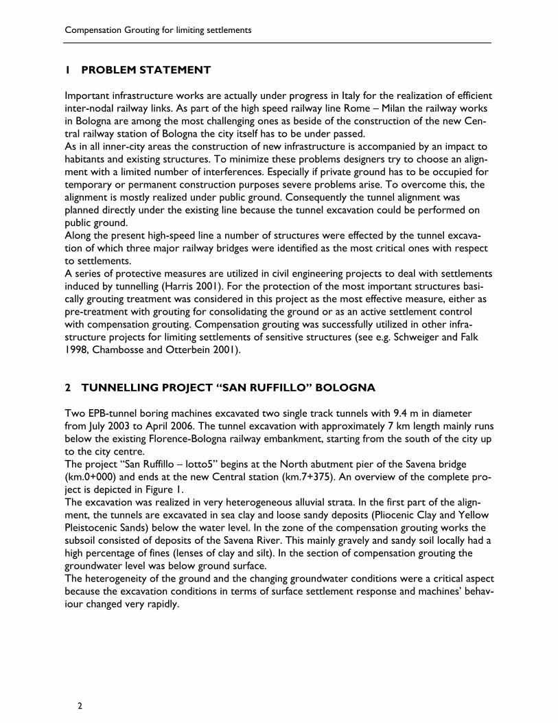
4 COMPENSATION GROUTING The brick-made bridge “Ponte Via Emilia levante” is composed of one central arch with a span of about 16 m and 8 minor arches with about 10 m span. The bridge with a total length of 110 m carries the north and southbound tracks of the existing railway line (Figure 2). The bridge has a longitudinal joint along the whole length, so the structure comprises basically two bridges founded on a common footing. The level of the footing was controlled with two core drillings at up to 7 m below ground. Figures 3 and 4 depict the cross section and the plan view of the bridge, respectively.
Figure 2: Central part of the bridge “Ponte Via Emilia levante” The soil investigation showed a small layer of fill. Underneath a layer of middle and fine gravely sand was explored reaching to a maximum depth of about 7 m. Locally, lenses of silt and clay were found. The soil layer which basically affected the works was a medium dense to dense sandy gravel with a content of fines. The ground water level was explored underneath the zone of the tunnel driving. The axes of the twin tunnel were given at about 24 m below ground sur-face, which yields a cover between the footing sand the top heading of the tunnel section of more than 10 m. The grouting pipe array consisted of two levels of 48 grouting pipes. The maximum length of the TAM was 68 m with a curvature of 90 m. In total more than 5000 m of steel pipes were installed to cover 3200 m² of ground surface.

Compensation Grouting for limiting settlements
6
Figure 3. Bridge “Ponte Via Emilia levante” – cross section
Figure 4: Bridge “Ponte Via Emilia levante” – plan view
C. Kummerer, R. Thurner, Keller Grundbau GesmbH; A. Rigazio, A. Zamagni, Trevi Spa
7
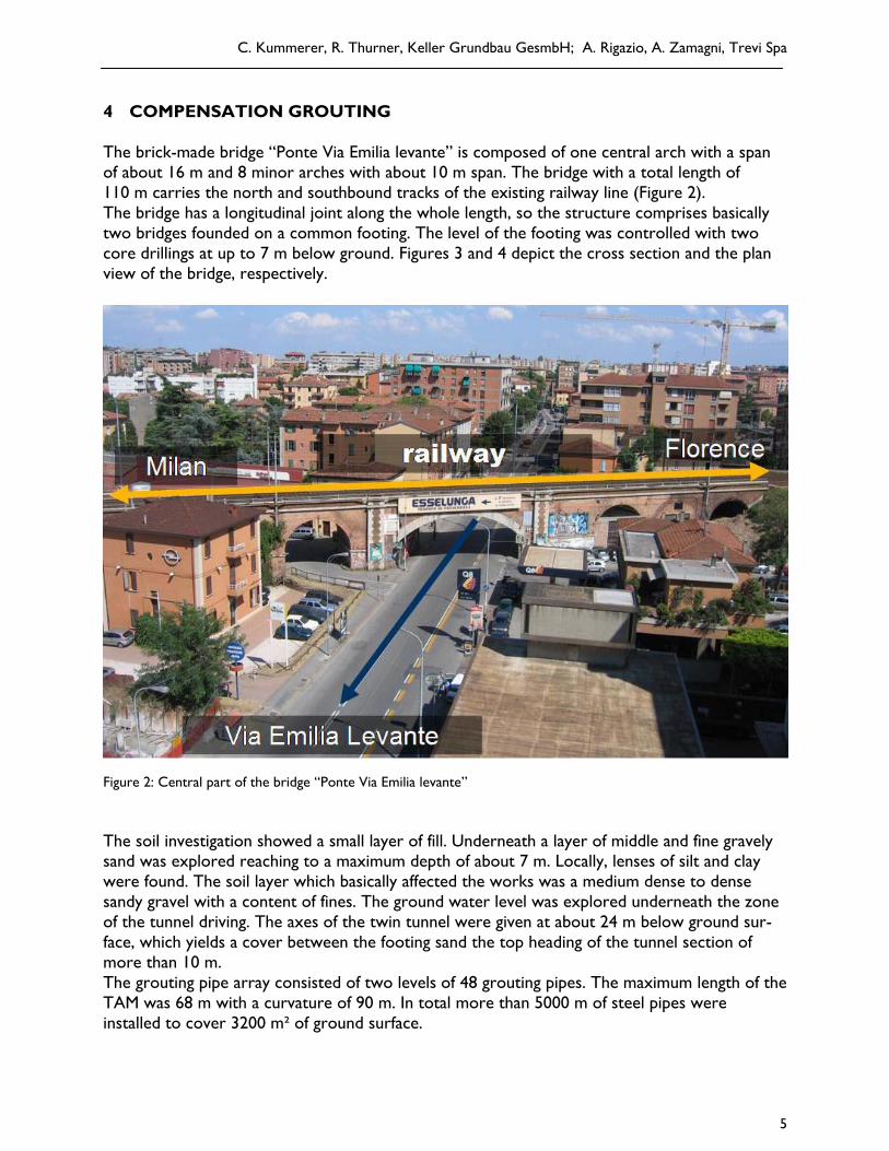
The liquid levelling system (Dekker et al. 2001) utilized 93 measurement points and 7 tempera-ture sensors in three levels, installed in August and September 2004. Due to the restrictions of realizing closed circuits, the monitoring system had to be divided in 8 circuits, each of them connected by means of individual transition points. The length of the different water circuits ranged between 80 m in the middle and the lower level and approx. 110 m in the upper level. Each water circuit has its own liquid reservoir. On each pier two water gauges were installed on the eastern and western side of the bridge, respectively. Moreover on each arch another water gauge was implemented. To obtain absolute readings, a reference water gauge was fixed at a dis-tance of more than 50 m from the bridge. With this comprehensive water levelling system a de-tailed monitoring of the deformation of the bridge was realized (Jakobs et al. 2006). In addition to the liquid levelling system, precise levelling and crack-meters were used. The data capturing was made to have the actual settlement monitored at all the water gauges with a 10 minute pe-riod.
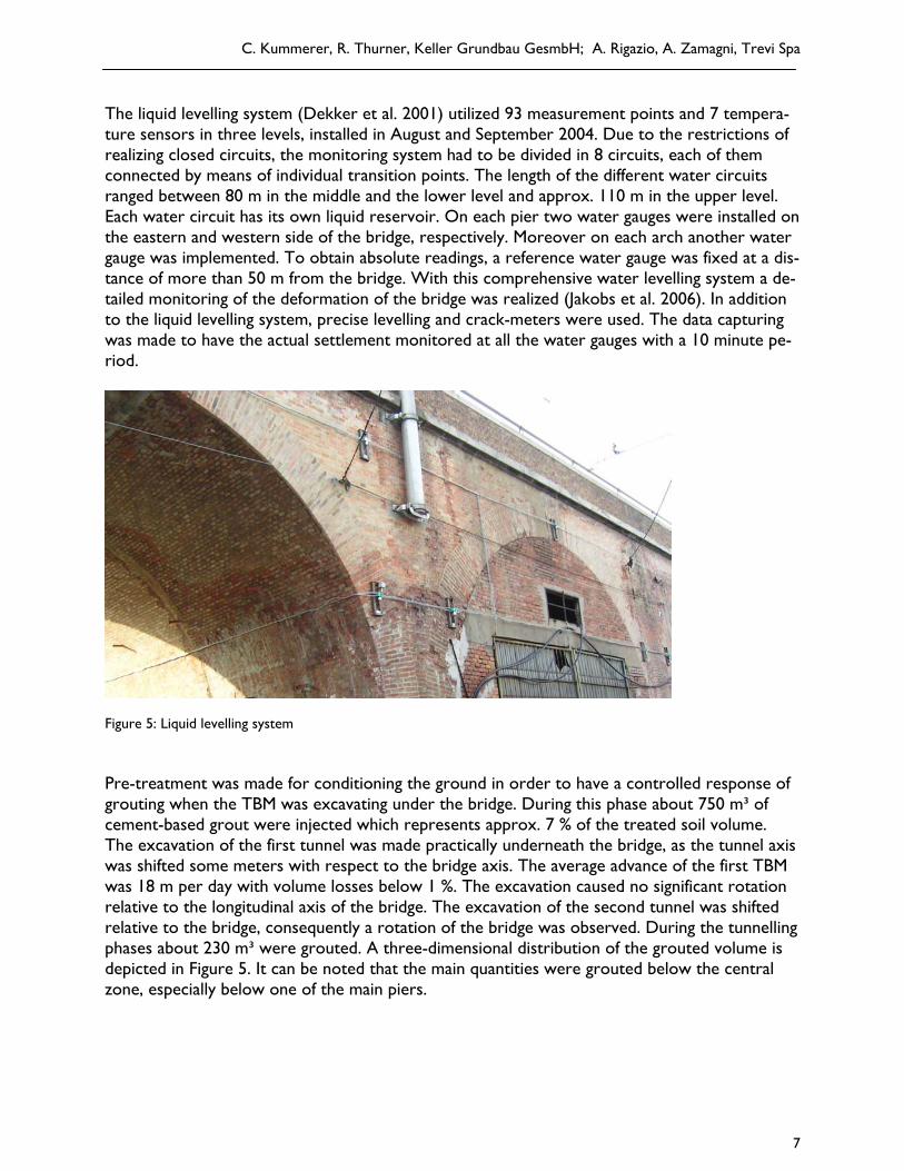
Figure 5: Liquid levelling system Pre-treatment was made for conditioning the ground in order to have a controlled response of grouting when the TBM was excavating under the bridge. During this phase about 750 m³ of cement-based grout were injected which represents approx. 7 % of the treated soil volume. The excavation of the first tunnel was made practically underneath the bridge, as the tunnel axis was shifted some meters with respect to the bridge axis. The average advance of the first TBM was 18 m per day with volume losses below 1 %. The excavation caused no significant rotation relative to the longitudinal axis of the bridge. The excavation of the second tunnel was shifted relative to the bridge, consequently a rotation of the bridge was observed. During the tunnelling phases about 230 m³ were grouted. A three-dimensional distribution of the grouted volume is depicted in Figure 5. It can be noted that the main quantities were grouted below the central zone, especially below one of the main piers.
Compensation Grouting for limiting settlements
8
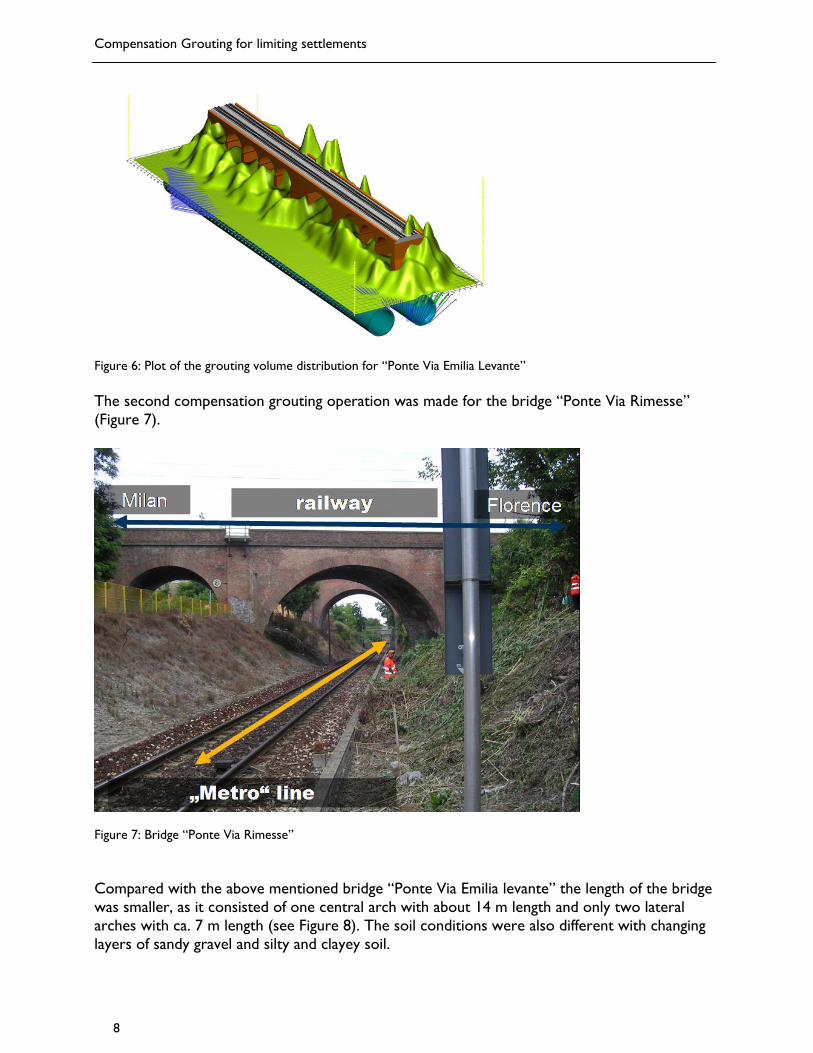
Figure 6: Plot of the grouting volume distribution for “Ponte Via Emilia Levante” The second compensation grouting operation was made for the bridge “Ponte Via Rimesse” (Figure 7).
Figure 7: Bridge “Ponte Via Rimesse” Compared with the above mentioned bridge “Ponte Via Emilia levante” the length of the bridge was smaller, as it consisted of one central arch with about 14 m length and only two lateral arches with ca. 7 m length (see Figure 8). The soil conditions were also different with changing layers of sandy gravel and silty and clayey soil.
C. Kummerer, R. Thurner, Keller Grundbau GesmbH; A. Rigazio, A. Zamagni, Trevi Spa
9
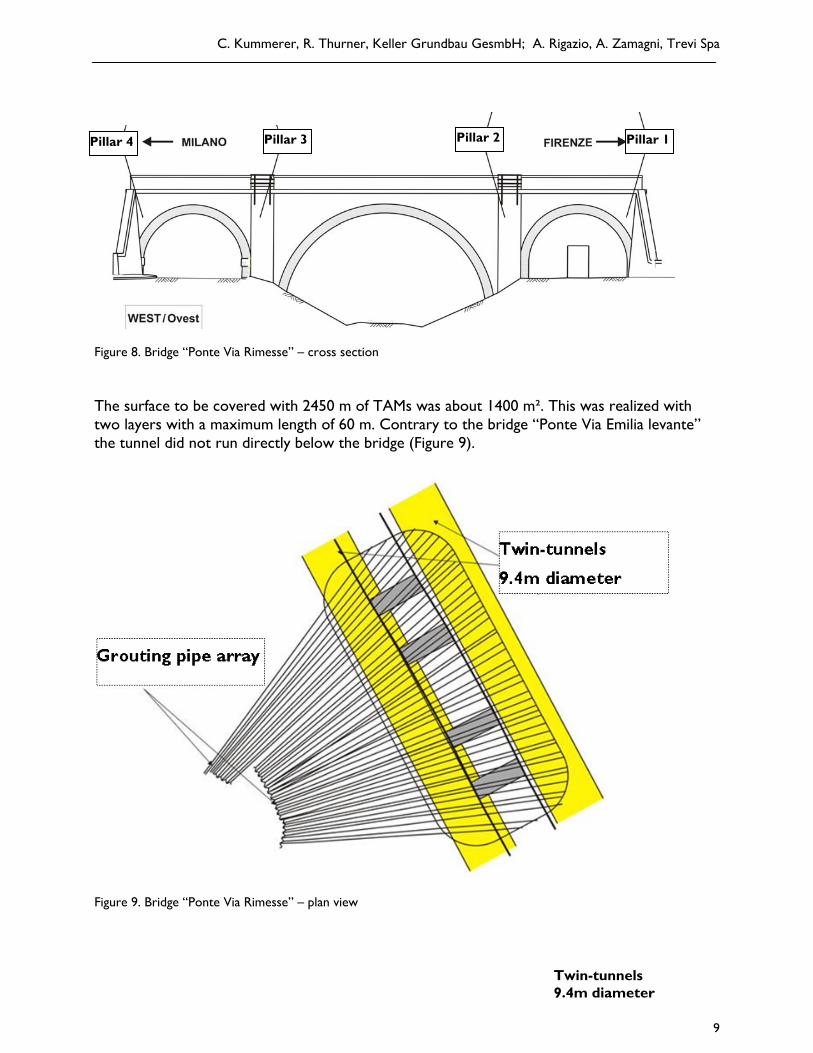
Figure 8. Bridge “Ponte Via Rimesse” – cross section The surface to be covered with 2450 m of TAMs was about 1400 m². This was realized with two layers with a maximum length of 60 m. Contrary to the bridge “Ponte Via Emilia levante” the tunnel did not run directly below the bridge (Figure 9).
Figure 9. Bridge “Ponte Via Rimesse” – plan view
Twin-tunnels 9.4m diameter
Pillar 3 Pillar 4 Pillar 2 Pillar 1
Compensation Grouting for limiting settlements
10
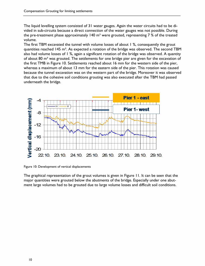
The liquid levelling system consisted of 31 water gauges. Again the water circuits had to be di-vided in sub-circuits because a direct connection of the water gauges was not possible. During the pre-treatment phase approximately 140 m³ were grouted, representing 7 % of the treated volume. The first TBM excavated the tunnel with volume losses of about 1 %, consequently the grout quantities reached 145 m³. As expected a rotation of the bridge was observed. The second TBM also had volume losses of 1 %, again a significant rotation of the bridge was observed. A quantity of about 80 m³ was grouted. The settlements for one bridge pier are given for the excavation of the first TMB in Figure 10. Settlements reached about 16 mm for the western side of the pier, whereas a maximum of about 13 mm for the eastern side of the pier. This rotation was caused because the tunnel excavation was on the western part of the bridge. Moreover it was observed that due to the cohesive soil conditions grouting was also executed after the TBM had passed underneath the bridge.
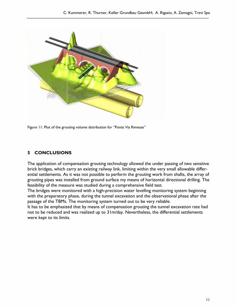
Figure 10: Development of vertical displacements The graphical representation of the grout volumes is given in Figure 11. It can be seen that the major quantities were grouted below the abutments of the bridge. Especially under one abut-ment large volumes had to be grouted due to large volume losses and difficult soil conditions.
C. Kummerer, R. Thurner, Keller Grundbau GesmbH; A. Rigazio, A. Zamagni, Trevi Spa
11
Figure 11: Plot of the grouting volume distribution for “Ponte Via Rimesse” 5 CONCLUSIONS The application of compensation grouting technology allowed the under passing of two sensitive brick bridges, which carry an existing railway link, limiting within the very small allowable differ-ential settlements. As it was not possible to perform the grouting work from shafts, the array of grouting pipes was installed from ground surface my means of horizontal directional drilling. The feasibility of the measure was studied during a comprehensive field test. The bridges were monitored with a high-precision water levelling monitoring system beginning with the preparatory phase, during the tunnel excavation and the observational phase after the passage of the TBMs. The monitoring system turned out to be very reliable. It has to be emphasized that by means of compensation grouting the tunnel excavation rate had not to be reduced and was realized up to 31m/day. Nevertheless, the differential settlements were kept to its limits.

Compensation Grouting for limiting settlements
12
REFERENCES Chambosse, G., Otterbein R. 2001. Central Station Antwerp. Compensation grouting under high loaded foun-dations. Proc. Conf. on building response on tunnelling. Case studies from Construction of Jubilee Line Extension, London 2001, Burland et al. (eds.), Th. Telford, London. Dekker, H., Jakobs M., Otterbein R. 2001. Erfahrungen beim Einsatz der Druckschlauchwaage zur Höhen-überwachung setzungsempfindlicher Bauwerke. Der Bauingenieur, Band 76, Juni 2001. Falk, E. 2004. Soil fracturing. Ground improvement, 2nd ed. Moseley & Kirsch, 220-251. Harris, D.I. 2001. Protective measures. Conference on Response of buildings to excavation – induced ground movements. Th. Telford, 135-176. Mair, R. 1994. Report on Session 4: Displacement grouting. Proc. Int. Conf. Grouting in the ground, London, 1992, Bell (ed.), T. Telford, London, 375-384. Schweiger, H.F., Falk, E. 1998. Reduction of settlements by compensation grouting – Numerical studies and experience from Lisbon underground. Proc. World Tunnel Congress, Sao Paolo, 1998, Negro & Ferreira (eds.), Balkema, Rotterdam, 1047-1052. Jakobs, M., Kummerer, C., Marchionni, V. 2006. The application of a hydrostatic levelling system under ex-treme temperature conditions for the control of a protective measure for the tunnelling under a railway bridge in Italy, Proceedings Conference Messen in der Geotechnik, Braunschweig, 191-208.