1000 Series Portable Beam Scale · 1000 Series Portable Beam Scale Model 1000 ... 03/13 9 51003 –...
14
51003 Revision 3–03/13 © 1996-2013 by Thurman Scale All rights reserved. 1000 Series Portable Beam Scale Model 1000 Installation Manual
Transcript of 1000 Series Portable Beam Scale · 1000 Series Portable Beam Scale Model 1000 ... 03/13 9 51003 –...

51003
Revision 3–03/13 © 1996-2013 by Thurman Scale All rights reserved.
1000 Series Portable Beam Scale Model 1000
Installation Manual

03/13 2 51003 – Rev 3
Amendment Record
1000 Series Portable Platform Scale
51003
Manufactured by Thurman Scale
4025 Lakeview Crossing
Groveport OH 43215
Created 02/96
Revision 1 02/96
Revision 2 11/12
Revision 3 03/13 Revised parts lists.
Disclaimer: Every effort has been made to provide complete and accurate information in this manual. However, although this manual may include a specifically identified warranty notice for the product, Thurman Scale makes no representations or warranties with respect to the contents of this manual, and reserves the right to make changes to this manual without notice when and as improvements are made.

03/13 3 51003 – Rev 3
Table of Contents
SECTION 1: INTRODUCTION ....................................................................................................... 4
1.1 Introduction & General Description ........................................................................................... 4
SECTION 2: DESCRIPTION........................................................................................................... 5
SECTION 3: INSTALLATION ......................................................................................................... 6
3.1 Unpacking ................................................................................................................................... 6
3.2 Assembly ..................................................................................................................................... 6
3.2.1 Wheel and Pillar Assembly ............................................................................................................... 6
3.2.2 Cap and Beam Assembly for Series 1000 Models ........................................................................... 7
3.3 Operation.................................................................................................................................... 9
3.3.1 Zeroing ............................................................................................................................................. 9
3.3.2 Weighing .......................................................................................................................................... 9
SECTION 4: PARTS ................................................................................................................... 10
4.1 1000 – lbs .................................................................................................................................. 10
4.2 1001 – kgs ................................................................................................................................. 12

03/13 4 51003 – Rev 3
Section 1: Introduction
1.1 INTRODUCTION & GENERAL DESCRIPTION
This manual provides information on installation, adjustment, and parts list for model 1000 Series portable platform scales. Please read carefully while assembling the scale. The scale is factory calibrated and supplied ready to be assembled and placed into service. For commercial applications, scale must be installed by a certified scale technician.
NOTE: Adjustments to the weighing accuracy should only be made by trained scale personnel. No modifications are to be made to this equipment.
Upon receipt, ensure that no shipping damage has occurred. Damage to the shipping carton must be noted by the receiving party, and made known to the shipper. Claims for shipping damage are made by the receiving party to the shipper.
It is the customer's/owner's responsibility to maintain the scale in good operating condition and to protect the scale from accidental damage.

03/13 5 51003 – Rev 3
Section 2: Description
The 1000 Series Portable Beam Scale is constructed with a cast iron base and cast iron lever system.
The indicating device is a mechanical beam (lbs. or kgs.) or with accessories, an electronic instrument for displaying the weight.
NOTE: The 1000/1001’s shipping weight is approximately 185 lbs. Please use caution to prevent injury, and or damage to the product.
Models and accessories:
Model# Ref # Description Shipping Wt
1000 50006 17.75" x 23.5" Platform, 1000 lbs. capacity, Beam indicator
185 lbs
1001 54851 17.75" x 23.5" Platform, 500 kg capacity, Beam indicator
185 lbs

03/13 6 51003 – Rev 3
Section 3: Installation
3.1 UNPACKING Check that all parts are included using the packing list. Check for component damage that may have occurred during shipping.
3.2 ASSEMBLY
CAUTION: The scale base assembly, as shipped, weighs 185 lbs., use caution when lifting.
3.2.1 Wheel and Pillar Assembly
NOTE: The descriptions below refer to Item No to describe parts. Use the parts list and Item No. in the list to identify those parts.
a. Set the scale base assembly (#4) upright on the floor.
b. Starting with an axle (#19), insert a cotter pin (#17) in one end, then place
one (1) washer (#18) & one (1) wheel (#16) over the open end.
c. Insert the axle's other end through BOTH holes in the base.
d. Place a wheel (#16), then 1 washer over the other end and insert a cotter pin.
e. Repeat steps b-d for the 2nd axle.
f. 'Center' the axles in the base, then insert the locking screws (#15) into the
tapped holes in the bottom of the base (directly under the axle holes).
g. Tighten the locking screws, then secure the lock nuts (#14).
h. Screw the two (2) pillar rods (#1) into the base in the two (2) tapped holes provided.
i. Place the pillar (#2) over the pillar rods with the cutouts facing to the left
and right of the platform
j. Insert the beam load rod (#35) down through the pillar, with the bent hook on top, loose swivel hook on the bottom.

Section 3: Installation
03/13 7 51003 – Rev 3
3.2.2 Cap and Beam Assembly for Series 1000 Models (Beam Installations):
a. Place the beam support (#39) over the pillar rods with the "hook" facing to the right (when facing the scale platform).
b. Place the beam cap (#45) over the pillar rods, with the beam cap extending
to the right.
c. Place washers then 'acorn' nuts (#44) over the pillar rods, hand tighten only.
d. Locate the loop assembly that will support the beam assembly from the beam cap. THIS LOOP MUST BE INSTALLED CORRECTLY TO ALLOW THE POISE TO SLIDE TO ZERO. Orient the open end of the loop assembly to face the end of the beam assembly when installing. Refer to section “Parts 1000 – lbs”.
e. Fit the loop over the pivot on the butt END of the beam.
f. Insert the beam into the cutouts in the pillar, then the beam tip through the
beam lock (#43) so that the beam's MIDDLE loop (on top) will go OVER the 'hook' on the beam support (thus hanging from the hook).
g. Put the UPPER end of the beam load rod through the large END loop on the
butt of the beam.
h. From the rear of the scale, locate the BOTTOM end of the beam load rod (the open part of the 'hook' on the bottom should face the scale base (inward).
i. Holding the rod's BOTTOM hook, put it UNDER the pivot on the END of the
scale lever by lifting on the long lever end from the bottom.
j. Fit the beam lock (#43) over the beam tip and align with the 2 holes in the beam cap and use the 2 screws to fasten the beam lock to the beam cap with the handle facing the scale platform.
k. Hang the counterpoise (#54) from the beam tip loop.
l. Set the sliding poise to zero and hand tighten the screw.
m. Check that the beam is straight and does not touch the sides of the trig lock.
n. Shift the cap if necessary to straighten, then tighten the “acorn” nuts
securely.
Section 3: Installation
03/13 8 51003 – Rev 3
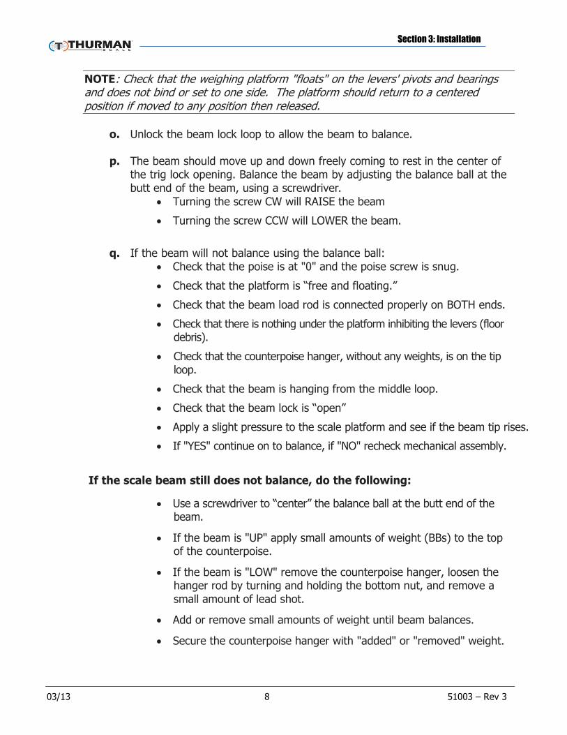
NOTE: Check that the weighing platform "floats" on the levers' pivots and bearings and does not bind or set to one side. The platform should return to a centered position if moved to any position then released.
o. Unlock the beam lock loop to allow the beam to balance.
p. The beam should move up and down freely coming to rest in the center of
the trig lock opening. Balance the beam by adjusting the balance ball at the butt end of the beam, using a screwdriver.
Turning the screw CW will RAISE the beam
Turning the screw CCW will LOWER the beam.
q. If the beam will not balance using the balance ball:
Check that the poise is at "0" and the poise screw is snug.
Check that the platform is “free and floating.”
Check that the beam load rod is connected properly on BOTH ends.
Check that there is nothing under the platform inhibiting the levers (floor debris).
Check that the counterpoise hanger, without any weights, is on the tip loop.
Check that the beam is hanging from the middle loop.
Check that the beam lock is “open”
Apply a slight pressure to the scale platform and see if the beam tip rises.
If "YES" continue on to balance, if "NO" recheck mechanical assembly.
If the scale beam still does not balance, do the following:
Use a screwdriver to “center” the balance ball at the butt end of the beam.
If the beam is "UP" apply small amounts of weight (BBs) to the top of the counterpoise.
If the beam is "LOW" remove the counterpoise hanger, loosen the hanger rod by turning and holding the bottom nut, and remove a small amount of lead shot.
Add or remove small amounts of weight until beam balances.
Secure the counterpoise hanger with "added" or "removed" weight.

Section 3: Installation
03/13 9 51003 – Rev 3
3.3 OPERATION 3.3.1 Zeroing
Before weighing an object, ensure that the scale is on ZERO with nothing on the platform. To do this, set the sliding poise to "0" release the beam lock, and observe the beam within the beam lock loop. (The beam should move from near the top to near the bottom eventually settling 'balancing' in the center). If not, adjust the zero balance ball using a flat blade screw driver.
If the beam stays at the top of the beam lock loop, turn the balance ball screw counter-clock-wise.
If the beam stays at the bottom of the beam lock loop, turn the balance ball screw clock-wise. Adjust the balance ball until the beam will balance at the center of the beam lock loop.
3.3.2 Weighing
Check that the beam lock is “ON” (lever flipped to the left).
Carefully place the object to be weighed in the platform center.
Run the sliding poise to the right end of the beam, and slowly release the beam lock.
If the beam stays at the bottom of the beam lock loop, slowly slide the poise to the left (decreasing) until the beam balances in the center. Read the weight on the beam at the poise's pointer.
If the beam stays at the top of the beam lock loop, add counter poise weights to the counterpoise until the beam “bottoms out” slowly slide the poise to the left (decreasing) until the beam balances in the center. Read the weight on the beam at the poise's pointer, and add the represented weight of all counterpoise weights used.

03/13 10 51003 – Rev 3
Section 4: Parts
4.1 1000 – LBS
Item No. Part No.
Description
1 71622 Pillar rod, long 2 58933 Pillar
3 95847 Platform cover
4 95848 Frame
5 95855 Cotter pin
6 58937 Bearing, platform
7 95856 Screw, Phillips Head
8 95857 Screw Allen
9 95858 Level, bubble
10 95859 Pin, corner loop
11 71623 Loop, corner
12 71624 Bearing, corner loop
13 71625 Cotter pin
10,11,12,13 58938 Corner loop assembly
14 95867 Hex nut
15 95868 Hex head bolt
16 95869 Wheel, 5" diameter
17 71628 Cotter pin
18 71629 Washer, flat
19 95870 Axle
24 95861 Pivot, load & fulcrum
25 72948 Short lever assy
26 58939 Center connection assembly
31 95863 Center pivot, long lever
33 72947 Long lever assy
34 95864 Long lever tip pivot
35 58934 Steelyard rod assembly
39 95839 Beam support
43 95840 Beam lock assembly
44 71592 Acorn nuts (2)
45 95841 Cap assembly
46 71593 Set of hex bolts
49 95843 Beam assembly (lb), includes: (beam, beam insert,
beam pivots, loops, poise w/screw, balance ball)
52 95842 Poise assembly
54 58935 Counterpoise assembly
55 58936 1 lb (100 lb) counterpoise weight
56 96853 2 lb (200 lb) counterpoise weight
57 95854 4 lb (400 lb) counterpoise weight
55, 56, 57 71596 1 Set of (lb) weights (1-58936, 2-96853, 1-95854) 1 95865 Platform locking pin
62 95866 Cotter pin, platform locking pin
NS 98545 Brass insert for beam. Unit = lbs. Includes insert for each side of the beam.

Section 4: PartsParts
03/13 11 51003 – Rev 3
1000 ‒ lbs –Diagram
Section 4: PartsParts
03/13 12 51003 – Rev 3
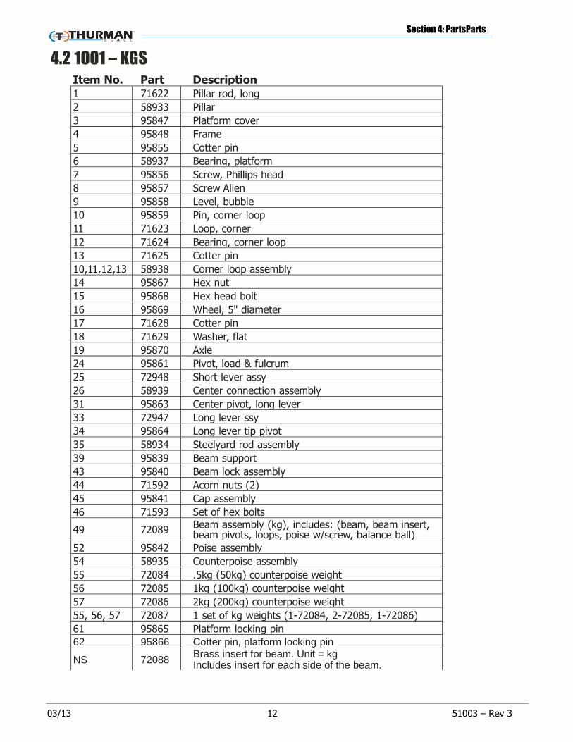
4.2 1001 – KGS
Item No. Part No.
Description 1 71622 Pillar rod, long
2 58933 Pillar
3 95847 Platform cover
4 95848 Frame
5 95855 Cotter pin
6 58937 Bearing, platform
7 95856 Screw, Phillips head
8 95857 Screw Allen
9 95858 Level, bubble
10 95859 Pin, corner loop
11 71623 Loop, corner
12 71624 Bearing, corner loop
13 71625 Cotter pin
10,11,12,13 58938 Corner loop assembly
14 95867 Hex nut
15 95868 Hex head bolt
16 95869 Wheel, 5" diameter
17 71628 Cotter pin
18 71629 Washer, flat
19 95870 Axle
24 95861 Pivot, load & fulcrum
25 72948 Short lever assy
26 58939 Center connection assembly
31 95863 Center pivot, long lever
33 72947 Long lever ssy
34 95864 Long lever tip pivot
35 58934 Steelyard rod assembly
39 95839 Beam support
43 95840 Beam lock assembly
44 71592 Acorn nuts (2)
45 95841 Cap assembly
46 71593 Set of hex bolts
49 72089 Beam assembly (kg), includes: (beam, beam insert, beam pivots, loops, poise w/screw, balance ball)
52 95842 Poise assembly
54 58935 Counterpoise assembly
55 72084 .5kg (50kg) counterpoise weight
56 72085 1kg (100kg) counterpoise weight
57 72086 2kg (200kg) counterpoise weight
55, 56, 57 72087 1 set of kg weights (1-72084, 2-72085, 1-72086)
61 95865 Platform locking pin
62 95866 Cotter pin, platform locking pin
NS 72088 Brass insert for beam. Unit = kg Includes insert for each side of the beam.

Section 4: PartsParts
03/13 13 51003 – Rev 3
1000 ‒ kgs – Diagram

1000 Series Portable Beam Scale
Manufactured by Thurman Scale, Inc.
821 Locust
Kansas City, MO 64106
www.Thurman.com
Installation Manual
Document 51003


![Multi-beam mask writer MBM-1000 - eBeam · CD (nm[3s]) 1.0 1.3 ... Correction functions (EBM series) ... Introduction and recent results of Multi-beam mask writer MBM-1000 Author:](https://static.fdocuments.net/doc/165x107/5b5ca0727f8b9ad2198ccd10/multi-beam-mask-writer-mbm-1000-cd-nm3s-10-13-correction-functions.jpg)